Recent Photonics Activities Under the NASA Electronic Parts and Packaging (NEPP) Program Charles Barnes*, Melanie Ott**, Allan Johnston*, Ken LaBel**, Robert Reed**, Cheryl Marshall** and Tets Miyahira* *Jet Propulsion Laboratory, California Institute of Technology **NASA Goddard Space Flight Center ABSTRACT With the rapidly increasing insertion of photonic devices, circuits and subsystems into NASA spacecraft, a variety of issues associated with reliability and radiation tolerance have arisen. In this paper, we discuss these issues from the perspective of the work currently ongoing in the NASA Electronic Parts and Packaging (NEPP) Program. This Program is focused on evaluating the reliability and radiation response of advanced and emerging microelectronics and photonics technologies of interest to NASA spacecraft system designers. Examples to be discussed include radiation studies of various optoelectronic devices and reliability of photonic components. These studies have been motivated in part by problems observed in space that include the failure of optocouplers on TOPEX/Poseidon, and the observation of single event-induced transients in the Hubble Space Telescope. 1. INTRODUCTION The qualification of microelectronic and photonic devices for space applications is challenging and difficult because the space environment presents a variety of stressing factors that these devices must survive so that mission success is not jeopardized. As shown in Figure 1 for the various phases of a typical Mars mission, these environmental factors include a wide variety of effects that can cause photonic devices and circuits to degrade and possibly fail completely. Several of these environmental effects are always present in a NASA mission, such as vibration effects during launch, but the dominant, most severe effect can vary dramatically depending on the mission scenario. Unlike missions to the Jovian system where radiation is usually the dominant factor, total ionizing dose (TID) is relatively low for Mars missions such as that in Figure 1, and low temperature effects and contamination, especially for Marian surface assets, can be very important. In contrast, for low Earth orbit (LEO) missions, such as the International Space Station (ISS) and the Shuttle, solar flare-induced radiation effects, both TID and single event effects (SEE), and aging effects for long missions are often significant. The important point to be made, however, is that space qualification of photonics for all NASA mis- sions is difficult and challenging, especially for commercial off-the-shelf (COTS) photonic components which are not intended for use in the space environment. The NASA Parts and Packaging (NEPP) Program is a NASA multi-Center Program whose objective is to assess the reliability and radiation tolerance of newly available COTS and emerging electronic and photonic parts and packaging technologies in order to facilitate the low-risk insertion of microelectronics and photonics technologies in NASA systems. In meeting this objective, the NEPP Program evaluates a wide variety of photonics components including optocouplers, LEDs, laser diodes, optical fibers, modulators, detectors, fiber optic links and accompanying conditioning and amplification electronics. These evaluations take into account those environmental parameters that can adversely affect the performance of these photonic components. As indicated in Figure 1, these include operation at very low temperatures, exposure to different types of radiation, damage and misalignment due to mechanical shock and vibration, aging effects and thermal cycling. In this paper, we provide a few recent examples of this work. *[email protected]; phone (818) 354-4467; FAX (818) 393-4419; Jet Propulsion Laboratory, 4800 Oak Grove Drive, M.S. 303-202, Pasadena, CA 91109 **[email protected]; (301) 286-0127; FAX (301) 286-1695; NASA, Goddard Space Flight Center, M.S. 562.0, Greenbelt, MD 20771

Welcome message from author
This document is posted to help you gain knowledge. Please leave a comment to let me know what you think about it! Share it to your friends and learn new things together.
Transcript

Recent Photonics Activities Under the NASA Electronic Parts andPackaging (NEPP) Program
Charles Barnes*, Melanie Ott**, Allan Johnston*, Ken LaBel**, Robert Reed**, Cheryl Marshall** andTets Miyahira*
*Jet Propulsion Laboratory, California Institute of Technology**NASA Goddard Space Flight Center
ABSTRACT
With the rapidly increasing insertion of photonic devices, circuits and subsystems into NASA spacecraft, a variety ofissues associated with reliability and radiation tolerance have arisen. In this paper, we discuss these issues from theperspective of the work currently ongoing in the NASA Electronic Parts and Packaging (NEPP) Program. This Program isfocused on evaluating the reliability and radiation response of advanced and emerging microelectronics and photonicstechnologies of interest to NASA spacecraft system designers. Examples to be discussed include radiation studies ofvarious optoelectronic devices and reliability of photonic components. These studies have been motivated in part byproblems observed in space that include the failure of optocouplers on TOPEX/Poseidon, and the observation of singleevent-induced transients in the Hubble Space Telescope.
1. INTRODUCTION
The qualification of microelectronic and photonic devices for space applications is challenging and difficult because thespace environment presents a variety of stressing factors that these devices must survive so that mission success is notjeopardized. As shown in Figure 1 for the various phases of a typical Mars mission, these environmental factors includea wide variety of effects that can cause photonic devices and circuits to degrade and possibly fail completely. Several ofthese environmental effects are always present in a NASA mission, such as vibration effects during launch, but thedominant, most severe effect can vary dramatically depending on the mission scenario. Unlike missions to the Joviansystem where radiation is usually the dominant factor, total ionizing dose (TID) is relatively low for Mars missions suchas that in Figure 1, and low temperature effects and contamination, especially for Marian surface assets, can be veryimportant. In contrast, for low Earth orbit (LEO) missions, such as the International Space Station (ISS) and the Shuttle,solar flare-induced radiation effects, both TID and single event effects (SEE), and aging effects for long missions areoften significant. The important point to be made, however, is that space qualification of photonics for all NASA mis-sions is difficult and challenging, especially for commercial off-the-shelf (COTS) photonic components which are notintended for use in the space environment.
The NASA Parts and Packaging (NEPP) Program is a NASA multi-Center Program whose objective is to assess thereliability and radiation tolerance of newly available COTS and emerging electronic and photonic parts and packagingtechnologies in order to facilitate the low-risk insertion of microelectronics and photonics technologies in NASAsystems. In meeting this objective, the NEPP Program evaluates a wide variety of photonics components includingoptocouplers, LEDs, laser diodes, optical fibers, modulators, detectors, fiber optic links and accompanying conditioningand amplification electronics. These evaluations take into account those environmental parameters that can adverselyaffect the performance of these photonic components. As indicated in Figure 1, these include operation at very lowtemperatures, exposure to different types of radiation, damage and misalignment due to mechanical shock and vibration,aging effects and thermal cycling. In this paper, we provide a few recent examples of this work.
*[email protected]; phone (818) 354-4467; FAX (818) 393-4419; Jet Propulsion Laboratory, 4800 Oak Grove Drive,M.S. 303-202, Pasadena, CA 91109
**[email protected]; (301) 286-0127; FAX (301) 286-1695; NASA, Goddard Space Flight Center, M.S. 562.0,Greenbelt, MD 20771

Mars Surface• Wind and dust, contamination• Thermal cycling• Low temperatures• Single event effects• Aging effects• Shock and vibration
Mars Orbit/Descent• Shock and vibration• Charging effects in ionosphere• Total dose effects from
electrons/solar flares• Single event effects
Transit• Aging effects• Total dose effects due to flares• Single event effects from GCR
and flares• Thermal cycling• Outgassing
Pre-Launch/Launch• Storage• Shock and vibration• Moisture ingress• Total dose effects due
to passage through belts
Mars Surface• Wind and dust, contamination• Thermal cycling• Low temperatures• Single event effects• Aging effects• Shock and vibration
Mars Surface• Wind and dust, contamination• Thermal cycling• Low temperatures• Single event effects• Aging effects• Shock and vibration
Mars Orbit/Descent• Shock and vibration• Charging effects in ionosphere• Total dose effects from
electrons/solar flares• Single event effects
Mars Orbit/Descent• Shock and vibration• Charging effects in ionosphere• Total dose effects from
electrons/solar flares• Single event effects
Transit• Aging effects• Total dose effects due to flares• Single event effects from GCR
and flares• Thermal cycling• Outgassing
Transit• Aging effects• Total dose effects due to flares• Single event effects from GCR
and flares• Thermal cycling• Outgassing
Pre-Launch/Launch• Storage• Shock and vibration• Moisture ingress• Total dose effects due
to passage through belts
Pre-Launch/Launch• Storage• Shock and vibration• Moisture ingress• Total dose effects due
to passage through belts
Figure 1. Impact of various space environmental factors on photonic devices for a typical Mars mission scenario.
2. RADIATION EVALUATIONS
Photonic components are susceptible to a variety of radiation effects which can degrade their performance during aspace mission, leading to reduced performance of spacecraft engineering systems or loss of science data from scienceinstruments. In addition, combinations of radiation with other environmental factors can lead to strong, negativesynergistic effects. For example, radiation tolerance is often much less at low temperature, and aging effects late in amission can reduce the margin available to accommodate radiation-induced reductions in performance. In spite of a longhistory1 of investigation of radiation effects in photonics, there are still many issues and problems to be solved prior tousing photonics in mission scenarios that have significant radiation exposure. This is true primarily because of thecontinual evolution of photonic technologies and the introduction of entirely new technologies. In subsequent Sectionswe provide examples of some recent work in this area under the NEPP Program.
2.1 Proton-Induced Displacement Damage in Optocouplers
Early investigations2 of optocoupler radiation sensitivity under the NEPP Program were prompted by optocouplerfailures observed on the TOPEX/Poseidon satellite, as shown in Figure 2. These failures occurred in thruster statuselectronic circuits, beginning at a little more than two years after launch. Fortunately, the status circuit failures did notimpact actual thruster operation.
The TOPEX/Poseidon optocoupler failures brought to light an important radiation hardness assurance (RHA) issue.Typical radiation testing of optocouplers had been done using Co-60 gamma ray sources to establish total ionizing dose(TID) susceptibility limits of these devices. Because optocouplers and their components are primarily susceptible todisplacement damage, their Co-60-determined TID resistance levels are quire high since gamma rays cause negligibledisplacement damage. The TOPEX/Poseidon failure levels, observed at much lower dose levels, suggested that protonsin the space environment caused the primary effect, and this was verified by comparing 4N49 optocoupler Co-60 re-sponse with that to protons2. These results are shown in Figure 3; which shows the greater sensitivity to protons.

A2-A ok ok – – – – – – – – FA2-B ok ok – – – – – – – – F
C3-A ok ok – – – – – – – – FC3-B ok ok – – – – – – – – F
A4-A – ok ok ok ok ok ok ok F F FA4-B – ok ok ok ok ok ok ok F F F
C4-A – ok ok ok ok ok ok ok ok ok FC4-B – ok ok ok ok ok ok ok F F F
Thruster 23 35 63 133 231 360 538 647 786 1014 1252
Days after Launch
First failures occur at 1.4 x 10¹⁰ p/cm2
A2-A ok ok – – – – – – – – FA2-B ok ok – – – – – – – – F
C3-A ok ok – – – – – – – – FC3-B ok ok – – – – – – – – F
A4-A – ok ok ok ok ok ok ok F F FA4-B – ok ok ok ok ok ok ok F F F
C4-A – ok ok ok ok ok ok ok ok ok FC4-B – ok ok ok ok ok ok ok F F F
Thruster 23 35 63 133 231 360 538 647 786 1014 1252
Days after Launch
First failures occur at 1.4 x 10¹⁰ p/cm21.4 x 1010 p/cm2
Figure 2. Truster status circuit optocoupler failures on the TOPEX/Poseidon satellite.
*
Cobalt-60 gamma rays
200 MeV protons
IF = 1 mA
OptekMicropac
1
0.1
0.01
0.001
Cha
nge
inC
urre
ntT
rans
ferR
atio
(nor
mal
ized
)
0 5 10 15 20 25 30
Equivalent Total Dose [krad (Si)] for Protons & Gammas
*
*
**
Neutrons
Proton, Neutron Fluence [p/cm2, n/cm2]
2x10111x1011 3x10¹¹ 4x10¹¹ 5x10110
Figure 3. Radiation sensitivity of 4N49 optocouplers to neutrons, protons and Co-60 gamma rays. Note the much greater sensitivityto protons and neutrons, which is attributed to the dominance of displacement damage in the optocoupler degradation, as opposed to
ionization effects caused by gamma rays. Current transfer ratio (CTR) is the ratio of optocoupler output current to input current.
In addition to the necessity for using the proper type of radiation (protons for displacement damage effects) to establishRHA, the determination of the overall radiation susceptibility of optocouplers is complicated by the fact that optocoup-lers contain components, LEDs and detectors, that exhibit different and varying radiation sensitivities. In the case ofproton-induced displacement damage, typical results for the varying sensitivity of optocoupler components is shown inFigure 4 for 4N49 optocouplers. The total degradation is made up of that due to both the LED and the detector. Note thatfor this particular case, the LED is significantly more sensitive to damage than the detector. In the next Section we willpresent additional discussion of LED effects.

Figure 4. Proton-induced displacement damage degradation of 4N49 optocoupler components.
Optocoupler Degradation
Optek
Micropac
Micropac
Optek
Micropac
Optek
1
0.1
0.01
0.0010 1 x 10¹¹ 2 x 10¹¹
IF = 1mA for all measurements
Photoresponse Degradation (measured with external source)
LED Degradation(measured with external detector)
Ch
ange
in C
TR o
r L
igh
t Ou
tput
(no
rmal
ized
)
3 x 10¹¹ 4 x 10¹¹ 5 x 10¹¹ 6 x 10¹¹
200 MeV protons
Proton Fluence (p/cm2)
Equivalent to 10 krad(Si)
More recent NEPP Program investigations3-6 of displacement damage effects in optocouplers have shown that the 4N49is one of the most sensitive devices, and that more advanced, high speed couplers are more resistant to displacementdamage. For example, in Figure 5 data are shown for the current-dependent proton-induced degradation in CTR for anadvanced optocoupler from Agilent. Note that, in comparison with the 4N49 in Figures 3 and 4, the radiation hardness ismuch greater for the Agilent device. In addition the CTRs for the Agilent devices are significantly larger than for the4N49s. The recent summary of results by O’Bryan, et al5 indicates that there is considerable variation in the displacementdamage hardness levels for available optocouplers. Not only is optocoupler selection for space missions complicated bythese variations and the complexity of the radiation response, but for COTS optocouplers, as is often true for COTSdigital and analog Si microcircuits, the radiation response of a given device type from a given manufacturer can vary withdate of purchase as shown in Figure 6 for 4N49s from Micropac. The implication of these data is that one must radiationtest each flight lot when using COTS optocouplers.
2.2 Light Emitting Diodes (LEDs)
Very often, a major fraction of the displacement damage sensitivity exhibited by optocouplers, such as those in Figures 3and 4, is due to degradation of the LED portion of the optocoupler. For this reason, extensive studies have been under-taken within the NEPP Program of displacement damage effects in a variety of LEDs. The recent proton irradiation datashown in Figure 7 illustrates this variation in radiation sensitivity7. Note that the longer wavelength amphotericallydoped (N and P-type dopants are both Si) GaAs LEDs are significantly more sensitive to proton-induced displacementdamage than the shorter wavelength Optodiode and Hamamatsu LEDs. The greater radiation sensitivity of the amphoter-ically doped LEDs has been attributed to differing current flow mechanisms and also basic differences in radiativerecombination mechanisms7. Basic physics aside, the primary concern for the space application user is the type of LEDused in COTS optocouplers selected for these applications. In NASA applications, there have been instances whenCOTS optocoupler manufacturers switched LED types within their optocouplers without informing users, leading toincreases in radiation sensitivity of the optocouplers. Thus, it is important to determine the type of LED used in theoptocoupler flight lot and if at all possible, avoid the use of optocouplers with amphoterically doped LEDs. An alterna-tive solution to the problem of optocoupler LED radiation susceptibility, is to work with the optocoupler manufacturer todevelop requirements and specifications for a radiation tolerant LED as an optocoupler component. This has beenaccomplished recently by specifying a double heterojunction hardened LED that lead to an order of maginitude improve-ment in optocoupler radiation resistance4.

Cur
rent
Tra
nsfe
rR
atio
LED Current (A)
0
70
10-6 10-5 10-3
90
10-4
80
50
20
4 x 10¹⁰
60
40
10
30
2 x 10¹⁰
1 x 10¹¹
2.5 x 10¹¹
5 x 10¹¹
Pretest
Specifiedforward current
Figure 5. Proton-induced degradation in CTR for Agilent HCPL-4701 optocouplers as a function of input LED current. Protonfluences in p/cm2 are shown at the right of each curve.
Figure 6. Variation of radiation response for different lots of Micropac 4N49 optocouplers over a seven year period.
CT
R(n
orm
aliz
ed)
Proton Fluence (p/cm2)
0.01
1
109 1010 1011
0.1
Lot 0139
Lot 9518
Lot 9810
Lot 9838
Selection of LEDs and optocouplers for use in space applications is further complicated by the complexities involved inextrapolating ground radiation test results to the actual space environment. As indicated in Figure 7, proton testing fordisplacement damage effects is usually done at only one proton energy to establish RHA for LEDs and optocouplers.However, protons in the space environment are characterized by a wide energy spectrum, and the efficiency by whichdisplacement damage is created in semiconductor devices is dependent on proton energy. Reed, et al8 have measured theenergy dependence of proton-induced LED degradation, and analyzed the results within the framework of expected non-ionizing energy loss (NIEL) in GaAs/AlGaAs in order to develop a method of extrapolating test results to the spaceenvironment. Representative results are shown in Figure 8 for single heterojunction LEDs irradiated at different protonenergies and accelerator facilities. The solid line represents a theoretical NIEL calculation for GaAs. Note that when thedata is nomalized to the NIEL calculation at 10 MeV proton energy, it agrees with the calculation at low and mid-energiesbut deviates significantly at high energies. However, as shown in Figure 8, the experimental NIEL data of Barry, et al9
agrees well with the single heterojunction data and also that for double heterojunction LEDs (not shown). As demon-strated by Reed, et al8, this agreement can form the basis for more accurate prediction of expected damage in space.

1.0
0.1
Ligh
tOut
put(
norm
aliz
ed)
109 1010 1011 1012
50 MeV protonsIF = 10 mA
890 nm(Optek)
Proton Fluence (p/cm2)
820 nm(Optodiode)
660 nm(Hamamatsu)
880 nm(Optodiode)
Amphotericallydoped devices
Figure 7. Proton-induced displacement damage degradation of four types of LEDs at moderate current levels.
Figure 8. LED degradation, expressed as lifetime-damage factor, normalized to agree with calculated NIEL values for 10 MeV protons.
0.1
0.01
0.001
0.000110 100 1000
100
10
1
0.1
Proton Energy (MeV)
NIE
Lin
GaA
s(M
eV-c
m2 /
gm)
Nor
mal
ized
Life
time-
Dam
age
Fact
or
Single Heterojunction LEDs(UC Davis CNL)Single Heterojunction LEDs(TRIUMF Low Energy Line)Single Heterojunction LEDs(TRIUMF High Energy Line)Barry et al. IEEE 1996
NEIL Calculation- Summers et al. 1988
1
2.3 Single Event Effects in Optocouplers
In addition to proton-induced optocoupler displacement damage effects, in themselves relatively complex, single eventeffects (SEE) also affect the performance of optocouplers, and can compound the RHA issues for these devices. WhileLEDs usually dominate the response to displacement damage effects in optocouplers, SEE occur in the detector portionof optocouplers, and also in fiber optic link (FOL) receivers. The SEE of concern are single event transients (SETs) thatcan produce large pulses of photocurrent that will disrupt optocoupler and FOL functionality. The occurrence of SETs isnot surprising since detectors are intended to transform electromagnetic radiation in the form of light emitted by the LEDinto photocurrent. Thus, protons, electrons and the heavy ions making up galactic cosmic rays (GCRs), all of whichproduce more intense ionization tracks than light, can be expected to cause large photocurrent pulses in detectors. Ofparticular interest are protons because they are more plentiful than GCRs and they cause siginificantly greater ionizationthan electrons.

A simple depiction of the mechanisms for proton-induced SETs is shown in Figure 9, along with a typical proton-inducedphotocurrent pulse. The flat disks schematically represent the active regions in the detector structures, which fordetectors appropriately designed for radiation environments are quite thin, often less than a few microns. In the case ofSi detectors, it is important to avoid diffusion limited carrier collection and confine photocurrent generation to thedepletion region. For a thin collection region, characteristic of the depletion layer in a relatively heavily doped junction,protons do not deposit enough energy to generate a significant pulse when traversing the collection region, that is thethin disk in Figure 9, at an angle to the large flat surface of greater than about 10o to 15o. Thus, there are two effectivemechanisms for creating large photocurrent pulses that can disrupt circuit function: 1) as shown at the top, when theproton traverses the active region along a path close to parallel to the surface (direct interaction), and 2) when there is anuclear reaction resulting in recoils that create heavy charge, as in the bottom illustration. Consequently, for directinteraction one expects a strong angular dependence. As shown in Figure 10, this direct interaction model has beenborne out by observations of strong angular dependence of SETs3,5,10.
100’s ? m
Direct Ionization AcrossLong Pathlengths
Nuclear Reaction Recoils
Proton- - - -
+ + -+ - - ++ + -+ - - +
+ + -+ - - ++ + -+ - - ++ + -+ - - ++ + -+ - - ++ + -+ - - ++ + -+ - - +
+ + - + + -- - - -- - - -- - - -
+ + -+ -+ - + ++ - - + + -+ -+ + -
+ + -+ -+ + - + + -+ + -+ -
+ + -
Proton- + + -- + + -
-2
0
2
4
6
0 100 200 300Time (ns)
Ou
tpu
t (V
olt
s)100’s ? m
Direct Ionization AcrossLong Pathlengths
Direct Ionization AcrossLong Pathlengths
Nuclear Reaction Recoils
Proton- - - -
+ + -+ - - ++ + -+ - - +
+ + -+ - - ++ + -+ - - ++ + -+ - - ++ + -+ - - ++ + -+ - - ++ + -+ - - +
+ + - + + -- - - -- - - -- - - -
+ + -+ -+ - + ++ - - + + -+ -+ + -
+ + -+ -+ + - + + -+ + -+ -
+ + -
Proton- + + -- + + -
-2
0
2
4
6
0 100 200 300Time (ns)
Ou
tpu
t (V
olt
s)
6x10-07
Cro
ssS
ectio
n(c
m2 )
Angle of Incidence (deg)
5x10-07
4x10-07
3x10-07
2x10-07
1x10-07
00 20 40 60 80 100
Channel 1Channel 2
Figure 9. Model for two mechanisms for proton-induced single event transient photocurrent pulses as shown at the right.
Figure 10. Angular dependence of proton-induced SETs.
It has also been shown3,10,11 that the cross section for SET production decreases strongly with increasing optical powerimpinging on the detector in an optocoupler or on the FOL receiver. The SET cross section also depends on data rate,and is greater in faster, high speed optocouplers and FOLs. These dependencies and various filtering techniques can beused to mitigate SETs and prevent them from producing false output signals in optocouplers and high speed FOLs.
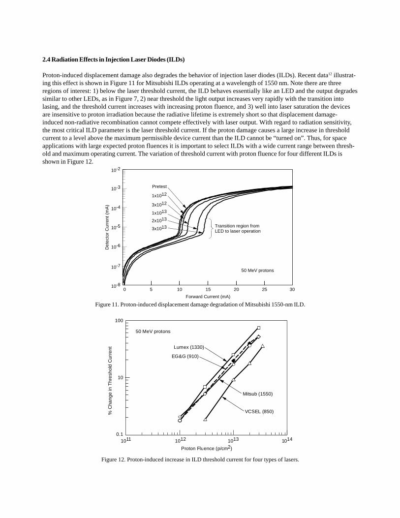
2.4 Radiation Effects in Injection Laser Diodes (ILDs)
Proton-induced displacement damage also degrades the behavior of injection laser diodes (ILDs). Recent data12 illustrat-ing this effect is shown in Figure 11 for Mitsubishi ILDs operating at a wavelength of 1550 nm. Note there are threeregions of interest: 1) below the laser threshold current, the ILD behaves essentially like an LED and the output degradessimilar to other LEDs, as in Figure 7, 2) near threshold the light output increases very rapidly with the transition intolasing, and the threshold current increases with increasing proton fluence, and 3) well into laser saturation the devicesare insensitive to proton irradiation because the radiative lifetime is extremely short so that displacement damage-induced non-radiative recombination cannot compete effectively with laser output. With regard to radiation sensitivity,the most critical ILD parameter is the laser threshold current. If the proton damage causes a large increase in thresholdcurrent to a level above the maximum permissible device current than the ILD cannot be “turned on”. Thus, for spaceapplications with large expected proton fluences it is important to select ILDs with a wide current range between thresh-old and maximum operating current. The variation of threshold current with proton fluence for four different ILDs isshown in Figure 12.
Det
ecto
rC
urre
nt(m
A)
10-810 15 30
Pretest
Forward Current (mA)
1x10¹²
3x10¹²
1x10¹³
2x10¹³
3x10¹³
0
10-7
10-6
10-5
10-4
10-3
10-2
50 MeV protons
5 20 25
Transition region fromLED to laser operation
100
10
0.1
%C
hang
ein
Thr
esho
ldC
urre
nt
1011 1012 1013 1014
50 MeV protons
Proton Fluence (p/cm2)
Lumex (1330)
EG&G (910)
Mitsub (1550)
VCSEL (850)
Figure 11. Proton-induced displacement damage degradation of Mitsubishi 1550-nm ILD.
Figure 12. Proton-induced increase in ILD threshold current for four types of lasers.

35
30
25
20
15
10
0
Cha
nge
inT
hres
hold
Cur
rent
(%)
100 103 106 107
Lumex laser diode= 1300 nm 18 mA
Annealing Time (s)
All devices irradiated to 5x10¹³ p/cm2
101 102 104 105
5
5 mA
15 mA
Unbiased anneal
As a possible method of damage mitigation in ILDs, one may be able to take advantage of a relatively unique annealingphenomenon. Degraded ILDs are often observed to recover during forward current bias without any need for heating toinduce thermally stimulated annealing. Examples12 of this non-thermal annealing effect are shown in Figure 13 for a 1300-nm ILD. Note that if the ILD is unbiased at room temperature, there is no recovery of threshold current, but when thedevice is placed under forward bias the recovery is substantial. This non-thermal annealing effect, termed recombinationenhanced annealing, is due to the transfer of energy from a non-radiative recombination event at a displacement damage-induced non-radiative recombination defect center to lattice phonon energy. In GaAs and AlGaAs, the energy band gapis wide enough so that this lattice photon energy is sufficient to cause the defect to jump from one lattice site to anotherthus resulting in an annealing effect. One can envision exploiting this annealing effect by merely turning on the laserduring the mission after exposure to significant proton fluences.
Figure 13. Forward current-induced annealing of displacement damage in 1300-nm emitting ILDs.
2.5 Fiber Optic Cables
The effects of radiation on optical fibers and cables have been investigated over many years13, but RHA issues stillremain for application of fiber cables in NASA missions. The focus of work in the NEPP Program has been on fiber cablesfor use in the International Space Station (ISS) and the behavior of high speed FOLs for future use in NASA systems14,15.There is a parallel between Si microcircuits and optical fibers in the sense that radiation hardened microcircuits havebecome difficult to obtain so that space system designers have had to resort to COTS Si digital and analog microcircuits.Similarly, optical fibers hardened for the space environment have become very difficult to find, and this has requiredadditional radiation testing of COTS fiber cables to determine their radiation tolerance. A recent example of this work isshown in Figure 14 for total dose testing of a COTS graded index, germanium doped fiber cable manufactured by Lucent.As shown in Figure 14, 100 m lengths of fiber were irradiated at different relatively low dose rates and at two tempera-tures, +25oC and -25oC, with fiber attenuation measurements at a wavelength of 1300 nm. The total dose-induced attenua-tion in these fibers is due to the introduction of germanium-related color centers which is offset during irradiation by theannealing of these centers. The balance between the radiation-induced color center production rate and the color centerdisappearance due to annealing is influenced by several factors including fiber core doping level, fiber drawing charac-teristics, dose rate and temperature. Generally, the balance is shifted toward greater attenuation for higher dose rates andlower temperatures, in agreement with the data in Figure 14. As is often the case with doped fibers, the attenuationgrowth is essentially linear with irradiation time and does not exhibit saturation. It is interesting to note that the dose ratehas relatively greater influence on the attenuation than does temperature suggesting that the annealing rate is significantand not particularly dependent on temperature. We also note that the induced attenuation is quite high in these fibers; ofthe order of 0.4 dB/m at 30 krads at a dose rate of approximately 0.5 rad/s.
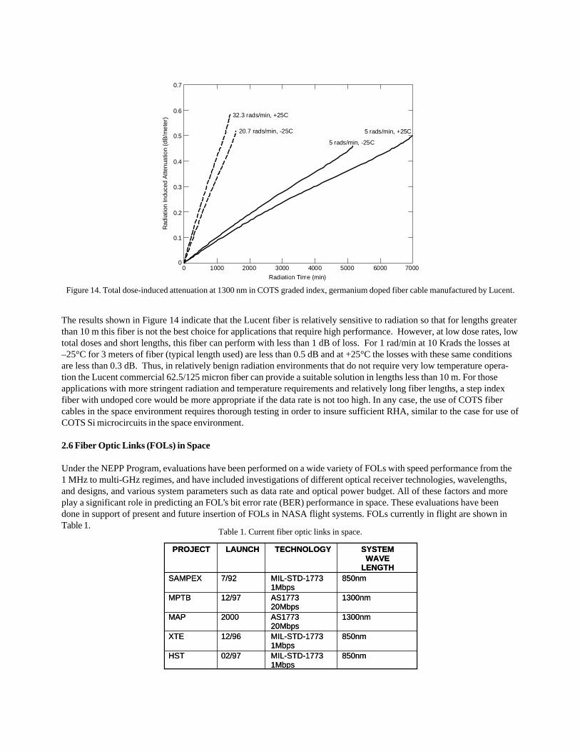
Figure 14. Total dose-induced attenuation at 1300 nm in COTS graded index, germanium doped fiber cable manufactured by Lucent.
The results shown in Figure 14 indicate that the Lucent fiber is relatively sensitive to radiation so that for lengths greaterthan 10 m this fiber is not the best choice for applications that require high performance. However, at low dose rates, lowtotal doses and short lengths, this fiber can perform with less than 1 dB of loss. For 1 rad/min at 10 Krads the losses at–25°C for 3 meters of fiber (typical length used) are less than 0.5 dB and at +25°C the losses with these same conditionsare less than 0.3 dB. Thus, in relatively benign radiation environments that do not require very low temperature opera-tion the Lucent commercial 62.5/125 micron fiber can provide a suitable solution in lengths less than 10 m. For thoseapplications with more stringent radiation and temperature requirements and relatively long fiber lengths, a step indexfiber with undoped core would be more appropriate if the data rate is not too high. In any case, the use of COTS fibercables in the space environment requires thorough testing in order to insure sufficient RHA, similar to the case for use ofCOTS Si microcircuits in the space environment.
2.6 Fiber Optic Links (FOLs) in Space
Under the NEPP Program, evaluations have been performed on a wide variety of FOLs with speed performance from the1 MHz to multi-GHz regimes, and have included investigations of different optical receiver technologies, wavelengths,and designs, and various system parameters such as data rate and optical power budget. All of these factors and moreplay a significant role in predicting an FOL’s bit error rate (BER) performance in space. These evaluations have beendone in support of present and future insertion of FOLs in NASA flight systems. FOLs currently in flight are shown inTable 1.
PROJECT LAUNCH TECHNOLOGY SYSTEMWAVE
LENGTHSAMPEX 7/92 MIL-STD-1773
1Mbps850nm
MPTB 12/97 AS177320Mbps
1300nm
MAP 2000 AS177320Mbps
1300nm
XTE 12/96 MIL-STD-17731Mbps
850nm
HST 02/97 MIL-STD-17731Mbps
850nm
PROJECT LAUNCH TECHNOLOGY SYSTEMWAVE
LENGTHSAMPEX 7/92 MIL-STD-1773
1Mbps850nm
MPTB 12/97 AS177320Mbps
1300nm
MAP 2000 AS177320Mbps
1300nm
XTE 12/96 MIL-STD-17731Mbps
850nm
HST 02/97 MIL-STD-17731Mbps
850nm
Table 1. Current fiber optic links in space.
0.7
0.6
03000
Radiation Time (min)
Rad
iatio
nIn
duce
dA
ttenu
atio
n(d
B/m
eter
)
0.5
0.4
0.3
0.2
0.1
200010000 4000 5000 6000 7000
32.3 rads/min, +25C
20.7 rads/min, -25C
5 rads/min, -25C
5 rads/min, +25C

2
4
6
8
10
12
14
16
18
20
Points are average perday of 6 month intervals
Predicted retry rate 18retries/day
0
Year/1st or 2nd half
1992
/2
Ave
rage
Num
ber
of R
etrie
s pe
r D
ay
1993
/1
1993
/2
1994
/1
1994
/2
1995
/1
1995
/2
1996
/1
1996
/2
2
4
6
8
10
12
14
16
18
20
Points are average perday of 6 month intervals
Predicted retry rate 18retries/day
0
Year/1st or 2nd half
1992
/2
Ave
rage
Num
ber
of R
etrie
s pe
r D
ay
1993
/1
1993
/2
1994
/1
1994
/2
1995
/1
1995
/2
1996
/1
1996
/2
2
4
6
8
10
12
14
16
18
20
Points are average perday of 6 month intervals
Predicted retry rate 18retries/day
0
Year/1st or 2nd half
1992
/2
Ave
rage
Num
ber
of R
etrie
s pe
r D
ay
1993
/1
1993
/2
1994
/1
1994
/2
1995
/1
1995
/2
1996
/1
1996
/2
Points are average perday of 6 month intervals
Predicted retry rate 18retries/day
0
Year/1st or 2nd half
1992
/2
Ave
rage
Num
ber
of R
etrie
s pe
r D
ay
1993
/1
1993
/2
1994
/1
1994
/2
1995
/1
1995
/2
1996
/1
1996
/2
0
Year/1st or 2nd half
1992
/2
Ave
rage
Num
ber
of R
etrie
s pe
r D
ay
1993
/1
1993
/2
1994
/1
1994
/2
1995
/1
1995
/2
1996
/1
1996
/2
Retry = SEU in 1773 photodetector
The SAMPEX 1773 data link has been in operation for 10 years and has been supported by extensive ground testing andanalysis of the link and its response to SETs in the link receiver. As indicated in a previous Section, detectors andreceivers are particularly sensitive to SETs, and as shown in Figure 15, the SAMPEX 1773 link has been experiencingabout 10 to 15 bus retries/day over the 10 year period due to SETs in the receiver. The analysis and modeling of linkbehavior led to the prediction of 18 retries/day, shown in Figure 15, that is close to the actual observed retry rate. Inaddition, these efforts led to the development of a robust system-level mitigation that involves detection of a corrupteddata transfer followed by the option of attempting a retry of the message. During a seven year flight period this retryprotocol failed only once. This extensive body of work has also produced FOL assessment tools and guidelines formitigating radiation effects in FOLs.
As noted in an earlier Section, Si detectors are susceptible to SETs because their active regions are relatively thick. Thus,in the case of a “first window” (800 nm to 850 nm) system, as for SAMPEX, one expects a relatively high SET rate in thereceiver. This has led to the use of links at longer wavelengths, such as those for MPTB and MAP (Table 1), that employIII-V-based detectors such as InGaAs, which have much thinner active regions and are not as prone to SET-induced falsesignal pulses.
Figure 15. SAMPEX fiber optic 1773 bus retry rates between 1992 and 1996 due to SETs in the link receiver. The gradual increase inactual retry rates is attributed to the transition from solar max to solar min during this period.
3. RELIABILITY EVALUATIONS
Under the NEPP Program, a significant amount of work has been done in the general area of the reliability, characteriza-tion and qualification of photonics components, such as optocouplers, LEDs, ILDs, large laser arrays, connectors, fibercables and detectors, for the space environment. These investigations have led to the publication of several papers andguidelines which are helpful to the space application user16-25. In this Section we briefly present a few examples of thiswork.
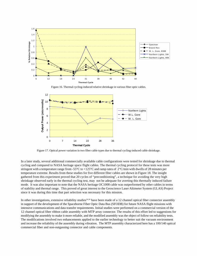
In support of ISS, problems associated with optical fiber jacketing and fiber cable configurations have been investigated.During the development of the ISS fiber cable harnessing, it was discovered that thermally induced cable componentshrinkage was a serious issue for cables that would be used in changing thermal environments. As shown in Figure 16,several cable types were subjected to thermal cycling to investigate cable shrinkage resulting from the cycling tests.Cables were tested up to 60 thermal cycles from -30°C to 140°C at 1°C/min with a 5 min dwell at both temperatureextremes. Note that all cables exhibit some shrinkage after a few 10s of cycles. Fiber cables from two manufacturers werealso optically monitored to detect the effect of shrinkage on attenuation of the fiber cables, and as shown in Figure 17,the Northern Lights cable showed a definite reduction in output power with increasing number of thermal cycles.
0
2
4
6
8
10
12
0 7 14 22 28 36
Thermal Cycle
Northern Lights
W.L. Gore
W. L. Gore
0
0.2
0.4
0.6
0.8
1
1.2
1.4
1.6
6 12 18 24 31 38 46 52 60
Therm al Cycle
%R
elat
ive
Sh
rin
kag
e
Spectran
Brand Rex
W . L. Gore, 8388
Northern Lights, SM
Northern Lights, MM
Figure 16. Thermal cycling-induced relative shrinkage in various fiber optic cables.
Figure 17. Optical power variation in two fiber cable types due to thermal cycling-induced cable shrinkage.
In a later study, several additional commercially available cable configurations were tested for shrinkage due to thermalcycling and compared to NASA heritage space flight cables. The thermal cycling protocol for these tests was morestringent with a temperature range from -55°C to +125°C and ramp rates of 2°C/min with dwells of 28 minutes pertemperature extreme. Results from these studies for five different fiber cables are shown in Figure 18. The insightgathered from this experiment proved that 20 cycles of “preconditioning”, a technique for avoiding the very highshrinkage observed early in the thermal cycling test, may not be adequate for averting this thermally induced failuremode. It was also important to note that the NASA heritage OC1008 cable was outperformed by other cables in termsof stability and thermal range. This proved of great interest to the Geoscience Laser Altimeter System (GLAS) Projectsince it was during this time that part selection was necessary for this mission.
In other investigations, extensive reliability studies16,26 have been made of a 12 channel optical fiber connector assemblyin support of the development of the Spaceborne Fiber Optic Data Bus (SFODB) for future NASA flight missions withintensive communications and data transfer requirements. Initial studies were performed on a commercial version of the12 channel optical fiber ribbon cable assembly with MTP array connector. The results of this effort led to suggestions formodifying the assembly to make it more reliable, and the modified assembly was the object of follow-on reliability tests.The modifications involved two enhancements applied to the earlier technology to better suit the vacuum environmentand increase the reliability of the assembly during vibration. The MTP assembly characterized here has a 100/140 opticalcommercial fiber and non-outgassing connector and cable components.

-0.200.000.200.400.600.801.001.201.401.601.802.002.20
0 8 16 24 32 40 48 56 64 72 80
Thermal Cycle
%Sh
rink
age FON1004
OC1614OC1008H06HL1
Figure 18. Thermal cycling-induced shrinkage in five different COTS fiber cables.
The modified assemblies were subjected to vibration and thermal cycling tests. During these tests, a 1310 nm lasersource was used to monitor optical power throughput for selected channels of the 12 channel array in order to determinethe effects of these environments on the optical power transmission. The parameters of the vibration tests were based ontypical launch conditions for components under prototype testing. Three assemblies were subjected to vibration testsin x, y and z directions, each for a duration of 3 minutes, as defined in Figure 19. The results of these tests for vibrationin the three directions are shown for one assembly in Figures 20, 21 and 22. Because an optical power meter was usedto monitor most of the channels, the results shown in these three Figures are “quasi-static” because the meter did notfollow the vibrations in real time. Note that the optical power variation is both positive and negative relative to thepretest power level. For all three tested assemblies and all three vibration axes, the quasi-static losses never exceeded0.5 dB for any of the channels tested, and as verified through visual inspection, none of the optical fiber interfaces weredamaged as a result of the vibration launch conditions used in these tests.
x
y zFigure 19. Orientation of MTP twelve channel ribbon connector assembly for vibration testing.
The modified assemblies were also subjected to thermal cycling tests with active optical power monitoring as in thevibration tests. The thermal cycling parameters were 38 cycles maximum, from –20° C to +85 °C, with a ramp rate of 1 °C/min and dwell times at the extremes of 25 minutes. For all three assemblies and all monitored channels, the maximumoptical transmission change observed during a single cycle was 1.6 dB, and the maximum change observed during anentire thermal cycling test was 1.8 dB. Typical results for one of the assemblies are shown in Figure 23. Note thatinitially there is a drop in optical transmission followed by a recovery during thermal cycling to an average opticaltransmission near that for pretest conditions. It is interesting to note that the general shape of these results is similar tothe thermal cycling-induced shrinkage data shown in Figures 16 and 18 in that there is a large initial change followed bya damping out of this change. Following the vibration and thermal cycling tests, all end faces in all the assemblies wereinspected and no damage was found. These results indicate that these assemblies are appropriate for space applica-tions as part of the SFODB.

0.500
0.400
Data Point (~5 sec/point)
Opt
ical
Tra
nsm
issi
on(d
B)
1 4
0.300
0.200
0.100
0.000
-0.200
7 10 13 16 19 22 25 28 31 34 37
Ch 1
Ch 3
Ch 5
Ch 8
Ch 10
Ch 12
-0.100
0.400
Data Point (~5 sec/point)
Opt
ical
Tran
smis
sion
(dB
)
1 4
0.300
0.200
0.100
0.000
-0.500
7 10 13 16 19 22 25 28 31 34 37
Ch 1
Ch 3
Ch 5
Ch 8
Ch 10
Ch 12
-0.100
-0.200
-0.300
-0.400
0.250
0.200
Data Point (~5 sec/point)
Opt
ical
Tra
nsm
issi
on(d
B)
1 4
0.150
0.100
0.050
0.000
-0.050
7 10 13 16 19 22 25 28 31 34 37
Ch 1
Ch 3
Ch 5
Ch 8
Ch 10
Ch 12
Figure 20. In situ optical power transmission during X-axis vibration of MTP connector assembly.
Figure 21. In situ optical power transmission during Y-axis vibration of MTP connector assembly.
Figure 22. In situ optical power transmission during Z-axis vibration of MTP connector assembly.

4. CONCLUSIONS
In this paper we have presented a sampling of some of the work on reliability and radiation tolerance of photonics thathas taken place recently under the NASA Electronic Parts & Packaging (NEPP) Program. A great deal more work has beenconducted within the NEPP Program, both on photonics and in other microelectronics areas, and this work can beaccessed on the NEPP Web site at http://nepp.nasa.gov. As a conclusion to this brief review, we wish to remark on somecommon themes emphasized by this work. They are as follows:
1. For both microelectronics and photonics, there is a continuing trend to use more and more COTS componentsin NASA flight systems. Several factors are responsible for this trend including the simple fact that spacequalified and hardened parts are not easily available. In addition, COTS parts often possess greater performancefor less cost and quicker delivery. The issue of cost, however, is not always obvious because the added cost ofupscreening and radiation testing required to characterize and qualify COTS can result in a greater total costthan that for space level parts. In any case, COTS photonic components will require continuing evaluationbefore they can be used in NASA systems without jeopardizing mission success.
2. Generally, the radiation issues for photonics that are of most importance for application in the space radiationenvironment are significantly different from those for Si microelectronics, especially for Si digital microcircuits.For example, with the exception of optical fibers, total ionizing dose (TID) effects are of much less importancefor photonics. For III-V-based photonic semiconductor components, displacement damage effects are of greaterijmportance so that the protons in the space environment are a key factor in determining the radiation tolerancefor specific mission scenarios. In the case of single event effects (SEE), only the receiver portion of a fiber opticlink (FOL) is susceptible, in contrast with Si memory and processor devices.
3. While in some cases it is appropriate to use characterization and qualification methods and techniquesemployed for Si digital and analog microelectronics as a baseline and “jumping off” point for qualifiation ofphotonic components, care must be taken in doing this becaues the important issues can differ significantly asin the case of radiation effects noted above. Failure mechanisms for photonic components can be quite differentfrom those for Si microelectronics, as can the techniques used to test for and reveal component failure condi-tions. Thus, care must be taken in not relying too heavily on analogies with the more established qualificationtechniques used for Si microelectronics.
5. ACKNOWLEDGEMENTS
The authors wish to acknowledge the many contributors to this work and the efforts of the NEPP Program. Many peoplehave contributed to the photonics work under NEPP, and we thank them for their efforts. We also wish to acknowledgethe NASA Headquarters Chief Engineer’s Office, Code AE, for their support of the NEPP Program.
0.04
0.02
-0.123000
Time (minutes)
Rel
ativ
eO
ptic
alT
rans
mis
sion
(dB
)
0
0
-0.02
-0.04
-0.06
-0.08
-0.1
20001000 4000 5000 6000 7000 8000 9000 10000
Figure 23. Thermal cycling-induced changes in optical power transmission for MTP connector assembly.
6. REFERENCES
1. C. Barnes, “The effects of radiation on optoelectronic devices”, SPIE, 721, p. 18 (1986).2. B. Rax, C. Lee. A. Johnston and C. Barnes, “Total dose and proton damage in optocouplers”, IEEE Trans. Nucl. Sci.,43, p. 3167 (1996).3. R. Reed, P. Marshall, A. Johnston, J. Barth, C. Marshall, K. LaBel, M. D’Ordine, H. Kim and M. Carts, “Emergingoptcoupler issues with energetic particle-induced transients and permanent radiation degradation”, IEEE Trans. Nucl.Sci., 45, p. 2833 (1998).4. A. Johnston and B. Rax, “Proton damage in linear and digital optocouplers”, IEEE Trans. Nucl. Sci., 47, p. 675 (2000).5. M. O’Bryan, K. LaBel, R. Reed, R. Ladbury, J. Howard Jr., S. Buchner, J. Barth, S. Kniffin, C. Seidleck, C. Marshall, P.Marshall, J. Kim, D. Hawkins, M. Carts, J. Forney, A. Sanders, S. Cox, C. Dunsmore and C. Palor, “Recent radiationdamage and single event effect results for candidate spacecraft electronics”, 2001 NSREC Workshop Record, p. 82.6. T. Miyahira and A. Johnston, “Trends in optocoupler radiation degradation”, 2002 IEEE NSREC, Phoenix, AZ.7. A. Johnston and T. Miyahira, “Characterization of proton damage in light emitting diodes”, IEEE Trans. Nucl. Sci., 47,p. 2500 (2000).8. R. Reed, P. Marshall, C. Marshall, R. Ladbury, H. Kim, L. Nguyen, J. Barth and K. LaBel, “Energy dependence of protondamage in AlGaAs light emitting diodes”, IEEE Trans. Nucl. Sci., 47, p. 2492 (2000).9. A. Barry. A. Houdayer, P. Hinrichsen, W. Letourneau and J. Vincent, “The energy dependence of lifetime-damageconstants in GaAs LEDs for 1 - 500 MeV Protons”, IEEE Trans. Nucl. Sci., 42, p. 2104 (1995).10. C. Marshall, P. Marshall, M. Carts, R. Reed, S. Baier and K. LaBel, “Characterization of transient error cross sections inhigh speed commercial fiber optic data links”, 2001 IEEE NSREC Workshop Record, p. 142.11. C. Marshall, P. Marshall, M. Carts, R. Reed and K. LaBel, “Proton-induced transient effects in a metal-semiconductor-metal (MSM) photodetector for optical-based data transfer”, IEEE Trans. Nucl. Sci., 45, p. 2842 (1998).12. A. Johnston, T. Miyahira and B. Rax, “Proton damage in advanced laser diodes”, IEEE Trans. Nucl. Sci., 48, p. 1764(2001).13. See for example, P. Lyons, L. Looney, H. Henschel, O. Kohn, H. Schmidt, K. Klein, H. Fabian, M. Mills and G. Nelson,“Influence of preform and draw conditions on UV transmission and transient radiation sensitivity on an optical fiber”,SPIE Fiber Optics Reliability: Benign and Adverse Environments III, 1174, p. 2 (1989).14. M. Ott, “Fiber optic cable assemblies for space flight II: thermal and radiation effects”, SPIE Photonics for SpaceEnvironments VI, 3440, p. 37 (1998).15. M. Ott and P. Friedberg, “Technology validation of optical fiber cables for space flight environments”, SPIE OpticalDevices for Fiber Communications II, 4216, p. 206 (2001).16. M. Ott and J. Bretthauer, “Twelve channel optical fiber connector assembly: from commercial off the shelf to spaceflight use”, SPIE Proc.: Photonics for Space Environments VI, 3440, p. 57 (1998).17. M. Bettencourt and M. Ott, “Fiber optic epoxy outgassing study for space flight applications”, NEPP Website.18. M. Ott and J. Plante, “Fiber optic cable assemblies for space flight applications: issues and remedies”, presented atthe 1997 World Aviation Congress and available on the NEPP Web site.19. J. Plante, M. Ott, J. Shaw and M. Garrison-Darrin, “Draft specification for optical cable, single, multimode fiber,hermetic, loose tube buffer, for space flight”, available on the NEPP Web site.20. J. Plante, “Evaluation report for the Amphenol-Bendix 453 miniature circular connector with Mil-T-29504 opticaltermini in a vibration environment”, available on the NEPP Web site.21. G. Lutes and M. Tu, “Photonic validation methods handbook”, D-18230, available on NEPP Web site.22. G. Lutes and M. Tu, “Photonic R & QA methods handbook”, D-18229, available on NEPP Web site.23. G. Lutes and M. Tu, “Photonic integration and usage guidelines manual”, D-18228, available on NEPP Web site.24. Q. Kim, C. Wrigley, T. Cunningham and B. Pain, “Space qualification of photonic devices”, NEPP Web site.25. Q. Kim, “Space qualification plan of optoelectronic and photonic devices for optical communication systems”,available on NEPP Web site.26. M. Ott, S. MacMurphy and P. Friedberg, “Characterization of the twelve channel 100/140 micron optical fiber, ribboncable and MTP array connector assembly for space flight environments”, SPIE Aerosense Conference April 2002,Enabling Photonic Technologies for Aerospace and Applications IV, Vol. 4732, also on NEPP Web site.
Related Documents