192 Recent Life Assessment Technology for Existing Steam Turbines ∗ Kiyoshi SAITO ∗∗ , Akira SAKUMA ∗∗ and Masataka FUKUDA ∗∗ A large and growing portion of electricity is produced by aging thermal power plants. Although excellent, high quality materials such as CrMoV steel and 12% Cr steel, etc. are used for the steam turbines, various forms of metallurgical degradation, due to creep and fatigue, etc. affect the parts and components during long-term operation at high temperature. Extending the life of steam turbines and ensuring high reliability requires life assessment technology, scheduled repairing, conversion, modification and upgrading of components in order to provide a stable power supply. As the high temperature parts and components of aged steam turbines are mainly metallurgically damaged by creep, fatigue and the interaction of both, life assessment combined with analytical and nondestructive methods is essential for realizing strategic plant life extension. We have developed a life assessment technology that takes material degradation into consideration, and have applied the procedure to more than 650 units and 2 500 components since 1983. A rotor bore replication device was developed in 1989 for the purpose of nondestructive observation of creep voids and supporting the validity of life prediction results. This paper describes the technical features and applied experience of recent life assessment technology for existing high temperature steam turbines. Key Words: Power Generation, Steam Turbine, Creep, Fatigue, Life Assessment 1. Introduction Most parts and components of steam turbines, as shown in Fig. 1, are made of steels containing various amounts of the principal alloying elements chromium, molybdenum, vanadium and nickel, etc. Most high tem- perature rotors, valves and blades, etc. are made of high strength materials such as CrMoV steels and 12% Cr steels, but these materials are metallurgically degraded under long-term operation at high temperature. Existing steam turbines are required to operate under severe con- ditions now and in the future, which means that the in- evitable accelerated deterioration of their parts and com- ponents such as high-pressure rotors and casing, etc. must be compensated. There are three kinds of examination methods for metallurgical damage assessment as shown in Table 1, that is, the destructive method, the nondestructive method and the analytical method, but they are not always effective and accurate due to their individual advantages and disad- vantages. First of all, although the destructive method can ∗ Received 31st August, 2005 (No. 05-4150) ∗∗ Toshiba Corporation, 2–4 Suehiro-cho, Tsurumi, Yoko- hama, Kanagawa 230–0045, Japan. E-mail: [email protected] directly evaluate the metallurgical property in laboratory testing devices, sample taking is extremely limited as op- erations because of the shape and construction of parts and components, and in addition, the analytical method must be used in combination in order to establish the test condi- tions. Secondly, among the several nondestructive meth- ods, hardness testing and replica examination are conve- nient and familiar, but there is room for improvement in evaluating process and precision, because both methods are problematic in relation to shapes and construction. Fi- nally, as analytical methods can obtain the analytical tem- perature and stress distribution in the parts and compo- nents by using finite element analyses, they are effective Fig. 1 Overview of 700 MW class steam turbine Series B, Vol. 49, No. 2, 2006 JSME International Journal

Welcome message from author
This document is posted to help you gain knowledge. Please leave a comment to let me know what you think about it! Share it to your friends and learn new things together.
Transcript
192
Recent Life Assessment Technology for Existing Steam Turbines∗
Kiyoshi SAITO∗∗, Akira SAKUMA∗∗ and Masataka FUKUDA∗∗
A large and growing portion of electricity is produced by aging thermal power plants.Although excellent, high quality materials such as CrMoV steel and 12% Cr steel, etc. areused for the steam turbines, various forms of metallurgical degradation, due to creep andfatigue, etc. affect the parts and components during long-term operation at high temperature.Extending the life of steam turbines and ensuring high reliability requires life assessmenttechnology, scheduled repairing, conversion, modification and upgrading of components inorder to provide a stable power supply. As the high temperature parts and components ofaged steam turbines are mainly metallurgically damaged by creep, fatigue and the interactionof both, life assessment combined with analytical and nondestructive methods is essential forrealizing strategic plant life extension. We have developed a life assessment technology thattakes material degradation into consideration, and have applied the procedure to more than650 units and 2 500 components since 1983. A rotor bore replication device was developed in1989 for the purpose of nondestructive observation of creep voids and supporting the validityof life prediction results. This paper describes the technical features and applied experienceof recent life assessment technology for existing high temperature steam turbines.
Key Words: Power Generation, Steam Turbine, Creep, Fatigue, Life Assessment
1. Introduction
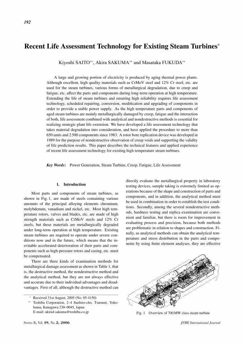
Most parts and components of steam turbines, asshown in Fig. 1, are made of steels containing variousamounts of the principal alloying elements chromium,molybdenum, vanadium and nickel, etc. Most high tem-perature rotors, valves and blades, etc. are made of highstrength materials such as CrMoV steels and 12% Crsteels, but these materials are metallurgically degradedunder long-term operation at high temperature. Existingsteam turbines are required to operate under severe con-ditions now and in the future, which means that the in-evitable accelerated deterioration of their parts and com-ponents such as high-pressure rotors and casing, etc. mustbe compensated.
There are three kinds of examination methods formetallurgical damage assessment as shown in Table 1, thatis, the destructive method, the nondestructive method andthe analytical method, but they are not always effectiveand accurate due to their individual advantages and disad-vantages. First of all, although the destructive method can
∗ Received 31st August, 2005 (No. 05-4150)∗∗ Toshiba Corporation, 2–4 Suehiro-cho, Tsurumi, Yoko-
hama, Kanagawa 230–0045, Japan.E-mail: [email protected]
directly evaluate the metallurgical property in laboratorytesting devices, sample taking is extremely limited as op-erations because of the shape and construction of parts andcomponents, and in addition, the analytical method mustbe used in combination in order to establish the test condi-tions. Secondly, among the several nondestructive meth-ods, hardness testing and replica examination are conve-nient and familiar, but there is room for improvement inevaluating process and precision, because both methodsare problematic in relation to shapes and construction. Fi-nally, as analytical methods can obtain the analytical tem-perature and stress distribution in the parts and compo-nents by using finite element analyses, they are effective
Fig. 1 Overview of 700 MW class steam turbine
Series B, Vol. 49, No. 2, 2006 JSME International Journal

193
Table 1 Comparison among life assessment methods
Table 2 Damage location, mechanisms and remedies for steam turbines
to evaluate the residual life and future estimate, but thereare pending issues between the evaluation and the actualmetallurgical property.
On the other hand, the combined method with the an-alytical and nondestructive methods is the most effectiveand useful in order to evaluate residual life as well as thecumulative damage due to creep, fatigue and the interac-tion of both, in combination with the numerous destructiveexamination results that are obtained from actual retiredrotors, casings, valves and so on.
2. Material Degradation of Steam Turbines
Table 2 shows the potential damage mechanisms andtypical remedial actions pertaining to the high tempera-ture parts and components of steam turbines. From theviewpoint of material mechanical property, softening andreduction in the strength of forged, rolled and casted partsand components such as rotors, blades, bolts, casings andvalves are caused by creep or fatigue due to high tempera-ture, stress, long-term operation and/or many start-ups andshut-downs.
JSME International Journal Series B, Vol. 49, No. 2, 2006

194
Fig. 2 Creep rupture properties depending on hardness forCrMoV steel
Fig. 3 Low cycle fatigue properties depending on hardness forCrMoV steel
To be more precise, creep rupture property and lowcycle fatigue life are reduced at high temperature in couplewith material softening, as shown in Figs. 2 and 3, whichare given by the material tests of the several retired ro-tors, casing and valves made of CrMo steel, CrMoV steeland 12Cr steel, etc(1), (2). As for microstructural change,carbide coarsening in the grain and grain boundary occursdue to thermal aging at the high temperature and low stressportion, on the other hand creep voids are formed at hightemperature and high stress portion, as shown in Fig. 4.
And with regard to material toughness, the fractureresistance is reduced by temper embrittlement at high tem-perature portion after long-term operation. Figure 5 showsembrittlement of a retired rotor, that is, the test results ofthe fracture appearance transition temperature (FATT) andthe fracture toughness(1), (3).
Thus, softening and embrittlement in the parts andcomponents of steam turbines progress with long-term ex-posure to high temperature and high stress, accompaniedby changes in material property. The numerous destruc-tive examination results that are obtained from the retired
Fig. 4 Example of microstructural changes caused by ageddeterioration
Fig. 5 Embrittlement of a retired HIP rotor
rotors, casings and valves, etc. are essential and useful incombined use with nondestructive measurement of soften-ing and embrittlement for life assessment of aged existingsteam turbines.
3. Technical Feature of Life Assessment
Figure 6 shows the outline of the life assessmentwhich consists of crack initiation life and crack growthlife(1), (2). Temperature and stress distribution on theparts and components are calculated by the finite elementmethod (FEM) by using operating condition and unit ser-vice history. Degraded material properties such as hightemperature creep strength, low cycle fatigue strength,toughness and metallurgical microstructure are detectedby nondestructive measurement of hardness inspection,embrittlement inspection and replica examination.
The cumulative damage due to creep and/or low cyclefatigue is expressed by the following equations, respec-tively.
φc =ttr
(1)
Series B, Vol. 49, No. 2, 2006 JSME International Journal

195
Fig. 6 Life assessment methodology for steam turbines
Fig. 7 Damage limit diagram for CrMoV steel
φ f =∑
i
ni
Nfi(2)
where, φc: consumed life due to creep damage, φ f : con-sumed life due to fatigue damage, t: total operation hours,tr: creep rupture time of material, ni: the number of unitstart up and shut down, Nfi: the number of cycles to fatiguecrack initiation of material, i: unit start up mode.
As the critical damage value that causes an initialcrack on the material varies depending on the combinationof φc and φ f , where sum is 1(one) or less, the residual lifecan be predicted under the condition of the degraded ma-terial properties. The damage envelope with experimentaldata for CrMoV steel is shown in Fig. 7. This diagram
significantly points out strong interaction feature betweencreep damage and fatigue damage, and remarkable accel-eration of crack initiation by adding a small amount of fa-tigue damage to creep damage. An accurate evaluation ofinteraction effect of creep damage and fatigue damage issignificant for steam turbine components, where the bothkinds of damages are superimposed(4).
Crack growth rates due to creep and/or low cycle fa-tigue assessed by fracture mechanics, are expressed by thefollowing equations, respectively.
dadt=Ao ·Km (3)
dadN=Co(∆K)n (4)
where, a: crack depth,dadt
: amount of crack growth per
time,dadN
: amount of crack growth per stress cycle, K:
stress intensity factor, ∆K: stress intensity factor range,Ao, m, Co, n: material constants depending upon the de-gree of embrittlement.
As mentioned above, as creep damage, fatigue dam-age and interaction of both are estimated based on the de-graded material properties as shown in Figs. 2 and 3, theresidual life to crack initiation is predicted reflecting thesubsequent operating plan. And furthermore, as the dete-riorated fracture resistance is estimated based on the de-graded material property as shown in Fig. 5, crack propa-gation life is also simulated.
In these ways, total synthetic judgement as the lifediagnosis is performed based on all obtained information,and the maintenance program is reviewed.
JSME International Journal Series B, Vol. 49, No. 2, 2006

196
4. Applied Experience of Life Assessment for ExisingSteam Turbines
Figure 8 shows an example of life diagnosis re-sults for a high and intermediate pressure outer casing ofCrMoV cast steel(5). The critical area is at the crotches
Fig. 8 Example of life assessment for steam turbine casing
Fig. 9 Example of life assessment for steam turbine rotor
between main steam inlet and hot reheat inlet on the outersurface of the lower half casing, and its consumed life wasestimated to φc = 1.3 due to creep damage and φ f = 0.001due to fatigue damage, respectively; that is, its residuallife was predicted to be none. Then, according to this di-agnosis result, detailed inspection of the above mentionedsurface was carried out at the next overhaul period, and acrack of 100 mm length was detected. Although the crackwas removed by skin peeling off up to 30 mm depth untilno indication was observed by magnetic particle inspec-tion, microstructure inspection of the replica method in-dicates significant creep voids remained at the crack re-moval area. It means this area was mainly composed ofcreep damage in spite of no magnetic particle indication.
Figure 9 shows another example for an intermedi-ate pressure rotor of CrMoV forged steel. Its consumed
Fig. 10 Configuration of rotor bore replication device
Fig. 11 Relationship between “A” parameter and creep damage for CrMoV rotor steel
Series B, Vol. 49, No. 2, 2006 JSME International Journal

197
life was estimated at φc = 0.89 due to creep damage andφ f < 0.001 due to fatigue damage at center bore potionof this rotor, respectively. The microstructure of the areathat is shown in Fig. 9 was detected by using the rotor borereplication device shown in Fig. 10. Replication techniquewas difficult to applying because of small bore diameter,but we have developed it in 1989, enabling observation ofthe metallurgical structure precisely(6).
The creep voids shown in Fig. 9 support the validityof diagnostic results. The residual life is also predictedfrom the consumed life, and subsequent progress of creepvoid formation could be explained by “A” parameter underthe high temperature creep condition as shown in Fig. 11.
These components mentioned above have been re-placed because their remaining lives were judged to beinsufficient based on the results of life diagnosis. Newlyreplaced components are applied to modified design andthe latest manufacturing process to contribute to extendthe life of steam turbines.
5. Conclusion
In order to provide a stable power supply, high re-liability and high maintainability are requisite conditionsfor steam turbines. And at the same time, effective life as-sessment is important to ensure that existing units undergoscheduled maintenance and life extension strategies(7). Weare continuing to develop and design further effective anduseful life assessment technologies for steam turbines andtheir auxiliary equipment based on the experience fromexisting units.
References
( 1 ) Kimura, K., Fujiyama, K., Saito, K. and Muramatsu,M., Life Assessment and Diagnosis System for SteamTurbine Components, Conference on Life Extensionand Assessment of Fossil Plants, EPRI, Washington,D.C., June 2–4, (1986).
( 2 ) Fujiyama, K., Kimura, K., Muramatsu, M., Kashiwaya,H. and Tsunoda, E., Life Diagnosis Experience andSystem Technology for Steam Turbine Components,Proceedings of International Conference on Life As-sessment and Extension, Hague, June 13–15, (1988),pp.20–30.
( 3 ) Saito, K., Kimura, K., Muramatsu, M., Kashiwaya, H.,Shoji, T. and Takahashi, H., Creep and Fatigue LifePrediction based on the Non-Destructive Assessment,Fossile Plant Inspection Workshop, EPRI, San Anto-nio, September 9–11, (1986).
( 4 ) Curran, R.M. and Wundt, B.M., Interpretative Reporton Notched and Unnotched Creep Fatigue InterspertionTests in Cr-Mo-V, 2 1/4Cr-1Mo and Type 304 Stain-less Steel, Publication MPC-8, ASME, (1978), pp.218–314.
( 5 ) Fujiwara, T. and Fujiyama, K., Extending Steam Tur-bine Life by Life Assessment, Toshiba Review, Vol.44,No.6 (1989), pp.490–493.
( 6 ) Saito, K. and Sakamoto, H., Life Assessment and Diag-nosis Techniques for Steam Turbine Components, To-shiba Review, Vol.46, No.6 (1991), pp.491–494.
( 7 ) Sakuma, A., Takahashi, T., Fujiwara, T. and Fukuda,M., Upgrading and Life Extension Technologies forExisting Steam Turbines, JSME Int. J., Ser. B, Vol.45,No.3 (2002), pp.492–498.
JSME International Journal Series B, Vol. 49, No. 2, 2006
Related Documents