RECENT DEVELOPMENTS IN PROFILE EXTRUSION: AUTOMATIC DESIGN OF EXTRUSION DIES AND CALIBRATORS J. M. Nóbrega and O. S. Carneiro Institute for Polymers and Composites, Department of Polymer Engineering, University of Minho, Campus de Azurém, 4800-058 Guimarães, Portugal e-mail: [email protected]; [email protected] This work describes the current state of the numerical codes that have been developed, by the authors, to aid the design of tools for thermoplastic profile extrusion. The main problems associated with the automatic design approach employed both for the extrusion die, forming stage, and calibrator, cooling/calibration stage, will be described. Two case studies are employed to illustrate the current code capabilities. Introduction Thermoplastic profiles have a large-scale application in the construction, medical, electric and electronic industries, among others. The term profile is commonly used to designate products of constant cross section that are obtained by the extrusion process. A typical extrusion line for the production of thermoplastic profiles generally comprises an extruder, a die, a calibration/cooling system, a haul-off unit and a saw, as shown in Figure 1. Figure 1 - Typical profile extrusion line (Battenfeld Extrusionstechnik GmbH). The major objective of any extrusion line is to produce the required profile at the highest rate and quality [1]. These goals are usually conflicting, i.e., the increase in speed generally affects the product quality negatively, and vice-versa. Therefore, the improvement of the extrusion line performance demands a systematic approach and a careful study of the phenomena involved in the

Welcome message from author
This document is posted to help you gain knowledge. Please leave a comment to let me know what you think about it! Share it to your friends and learn new things together.
Transcript
RECENT DEVELOPMENTS IN PROFILE EXTRUSION:
AUTOMATIC DESIGN OF EXTRUSION DIES AND CALIBRATORS
J. M. Nóbrega and O. S. Carneiro
Institute for Polymers and Composites, Department of Polymer Engineering, University of Minho, Campus de Azurém,
4800-058 Guimarães, Portugal
e-mail: [email protected]; [email protected]
This work describes the current state of the numerical codes that have been developed, by the authors, to aid the design
of tools for thermoplastic profile extrusion. The main problems associated with the automatic design approach
employed both for the extrusion die, forming stage, and calibrator, cooling/calibration stage, will be described. Two
case studies are employed to illustrate the current code capabilities.
Introduction
Thermoplastic profiles have a large-scale application in the construction, medical, electric and
electronic industries, among others. The term profile is commonly used to designate products of
constant cross section that are obtained by the extrusion process.
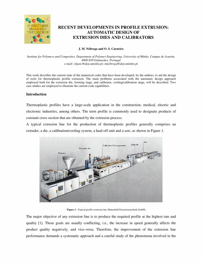
A typical extrusion line for the production of thermoplastic profiles generally comprises an
extruder, a die, a calibration/cooling system, a haul-off unit and a saw, as shown in Figure 1.
Figure 1 - Typical profile extrusion line (Battenfeld Extrusionstechnik GmbH).
The major objective of any extrusion line is to produce the required profile at the highest rate and
quality [1]. These goals are usually conflicting, i.e., the increase in speed generally affects the
product quality negatively, and vice-versa. Therefore, the improvement of the extrusion line
performance demands a systematic approach and a careful study of the phenomena involved in the
Anais do 9o Congresso Brasileiro de Polímeros
process [2]. The die and the calibration system are the extrusion line components that play a central
role in the establishment of the product dimensions, morphology and properties and are also those
that establish the maximum allowable production rate [3].
The difficulties to be faced in the design of an extrusion die are closely related to the complexity of
the profile to be produced. In fact, while the design of an extrusion die for the production of a rod is
almost straight-forward, in the case of a complex window profile it can be an extremely complex
process. From the geometrical point of view the extrusion die flow channel must transform a
circular cross section, corresponding to the melt leaving the extruder, into a shape similar to that of
the profile. Due to the large number of phenomena and restrictions involved and to the complexity
of the polymer melt rheological behaviour, extrusion die design was, and still is, more an art than a
science [4]. The design process is usually based on trial-and-error procedures, which are strongly
dependent on the designer knowledge and experience [4], often requiring several trials. As a
consequence, the design process is usually very time, material and equipment consuming, affecting
product price and performance [5], since it does not guarantee the achievement of an optimum
solution.
The complex behaviour of the polymer melt during flow through the die, together with the expected
slight variations of the operating conditions/polymer rheological properties, make it very difficult to
produce the required melt extrudate cross-section with precise and stable dimensions. For this
reason, the calibration/cooling system is used to establish the final most relevant dimensions of the
profile while cooling it down until a temperature that guarantees its shape along the downstream
stages [3]. Moreover, as the profile progresses along the line, it is subjected to a variety of external
forces (such as friction, buoyancy and compression), being necessary to guarantee that it is strong
enough to withstand these forces without deforming [3]. From a thermal point of view, the
calibration/cooling system must also ensure fast rate uniform cooling of the extrudate in order to
induce the adequate morphology and a reduced level of thermal residual stresses [6]. In practical
terms, the temperature gradient along both the profile contour and its thickness must be minimized
[7] and its average temperature at the calibration/cooling system outlet must fall bellow the
solidification temperature, in order to avoid subsequent melting [8]. Furthermore, to ensure that the
profile will be properly handled, before the saw point, all cross section temperatures must fall
bellow the solidification temperature.
Currently, and do to the availability of software packages for the mathematical modelling of
polymer melt flows, the trial-and-error design approach, usually employed for extrusions dies and
calibrators, is being progressively transformed from experimental into a numerical based operation
being, however, still dependent on the designer’s experience. The advantages of these approaches
Anais do 9o Congresso Brasileiro de Polímeros
are an overall reduction in the cost of the project and a higher probability of finding the optimal
solution. Recently, there is a trend towards the automatic design concept. The idea is to turn the die
design fully automatic, i.e., without any user intervention, and to guarantee the achievement of the
optimal solution.
This work describes the current state of the numerical codes that have been developed, by the
authors, to aid the design of extrusion dies [9] and calibrators [10] for thermoplastic profile
extrusion, based on the automatic design concept.
Extrusion Dies
The use of an automatic design approach for extrusion dies requires the resolution of some
problems, which include: i) the need to parameterize the die flow channel in order to enable an easy
modification of its geometry during the optimisation process; ii) the minimisation of the
computation time and hardware requirements needed for recurrent 3-D flow modelling. The
multiple simulations involved in an optimisation process make this feature critical since that, in
practical terms, the process should be performed within an acceptable time; iii) the need to evaluate
the quality, or performance, of each trial solution (die geometry), as in each iteration the required
automatic decisions will be based on this information. Evaluation is a key step of the optimisation
process since it will drive the search towards the final, optimal, solution; iv) the availability of an
efficient optimisation technique able to automatically search the space of possible solutions until an
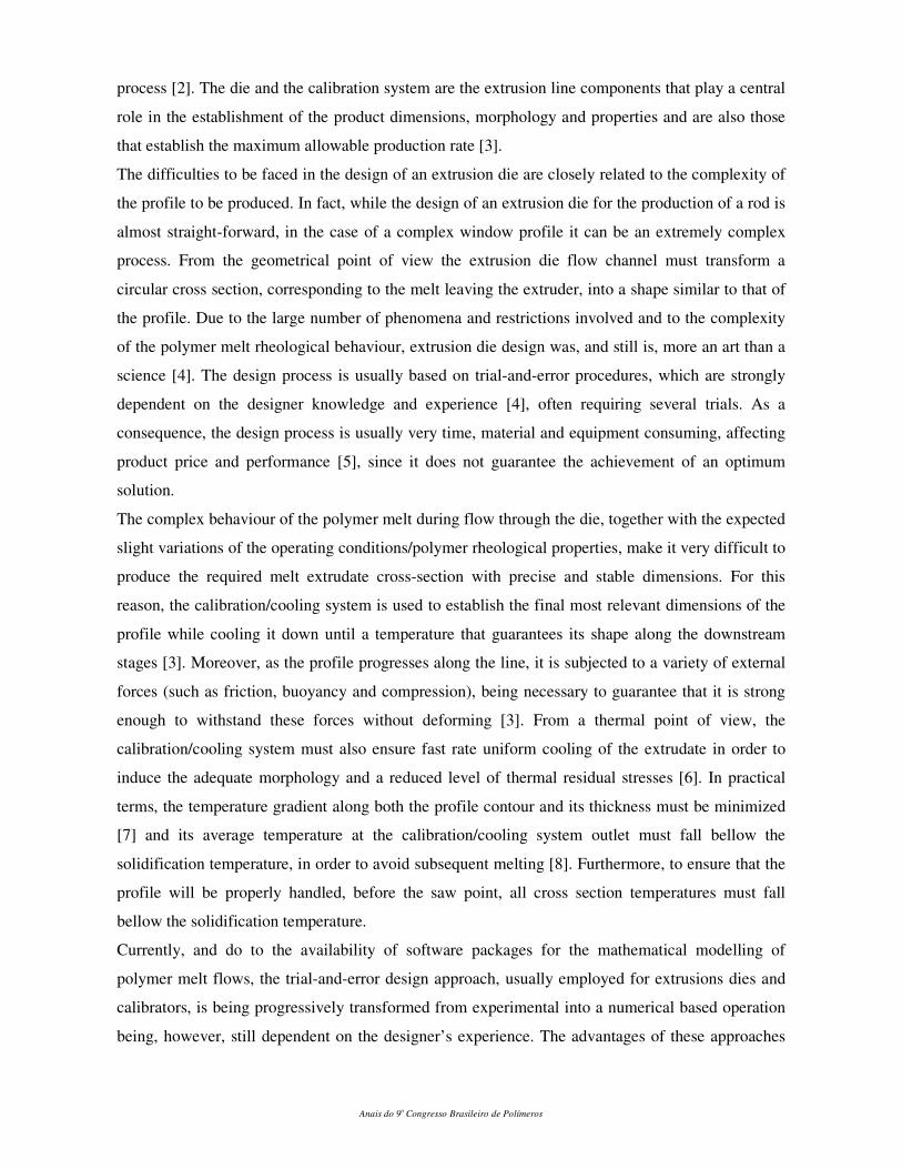
optimum is reached. The developed algorithm that solves all these issues, involves the steps
illustrated in the flowchart shown in Figure 2.
Figure 2 – Extrusion dies optimisation methodology flowchart.
Anais do 9o Congresso Brasileiro de Polímeros
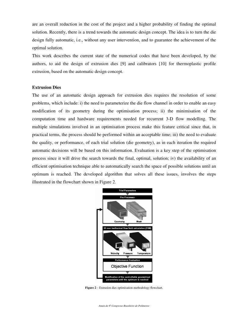
To illustrate the developed methodology the optimisation of the profile shown in Figure 3
was performed. The flow channel geometry was optimised using the methodology described
considering two different approaches: one exclusively based on length optimisation (which
will define DieL) and other exclusively based on thickness optimisation (defining DieT).
To access the results obtained, three modular instrumented extrusion dies were designed and
manufactured: one using the same ratio length/thickness for all elemental sections (DieINI),
matching the initial trial of the optimisation algorithm, and two corresponding to the
optimised geometries (DieL and DieT) proposed by the die design routines.
Figure 3 – Cross section of the parallel zone of the die as a case study.
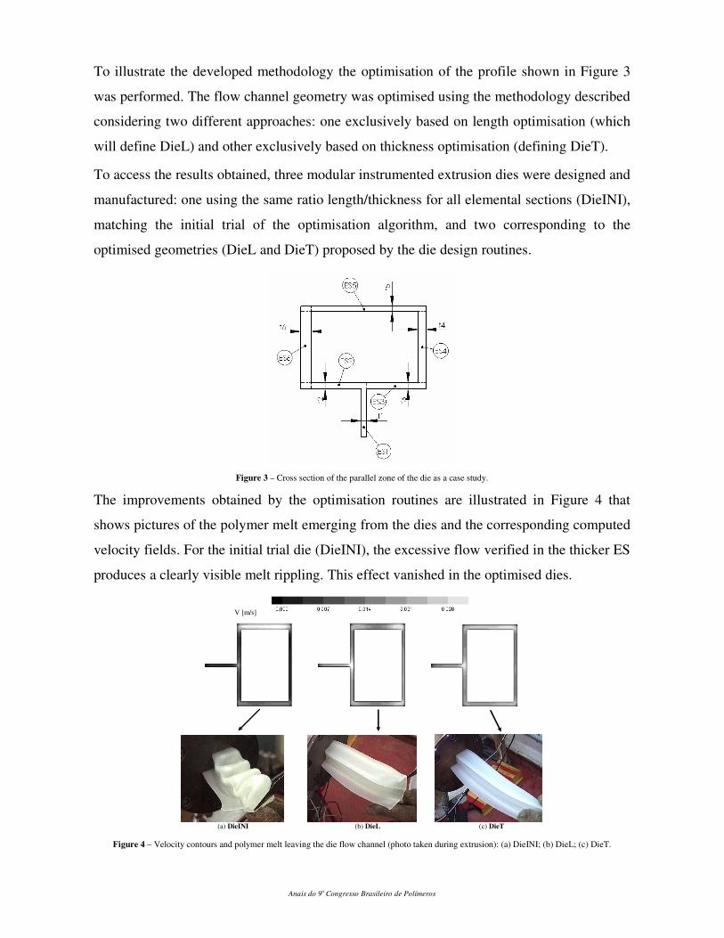
The improvements obtained by the optimisation routines are illustrated in Figure 4 that
shows pictures of the polymer melt emerging from the dies and the corresponding computed
velocity fields. For the initial trial die (DieINI), the excessive flow verified in the thicker ES
produces a clearly visible melt rippling. This effect vanished in the optimised dies.
V [m/s]
(a) DieINI (b) DieL (c) DieT
Figure 4 – Velocity contours and polymer melt leaving the die flow channel (photo taken during extrusion): (a) DieINI; (b) DieL; (c) DieT.
Anais do 9o Congresso Brasileiro de Polímeros
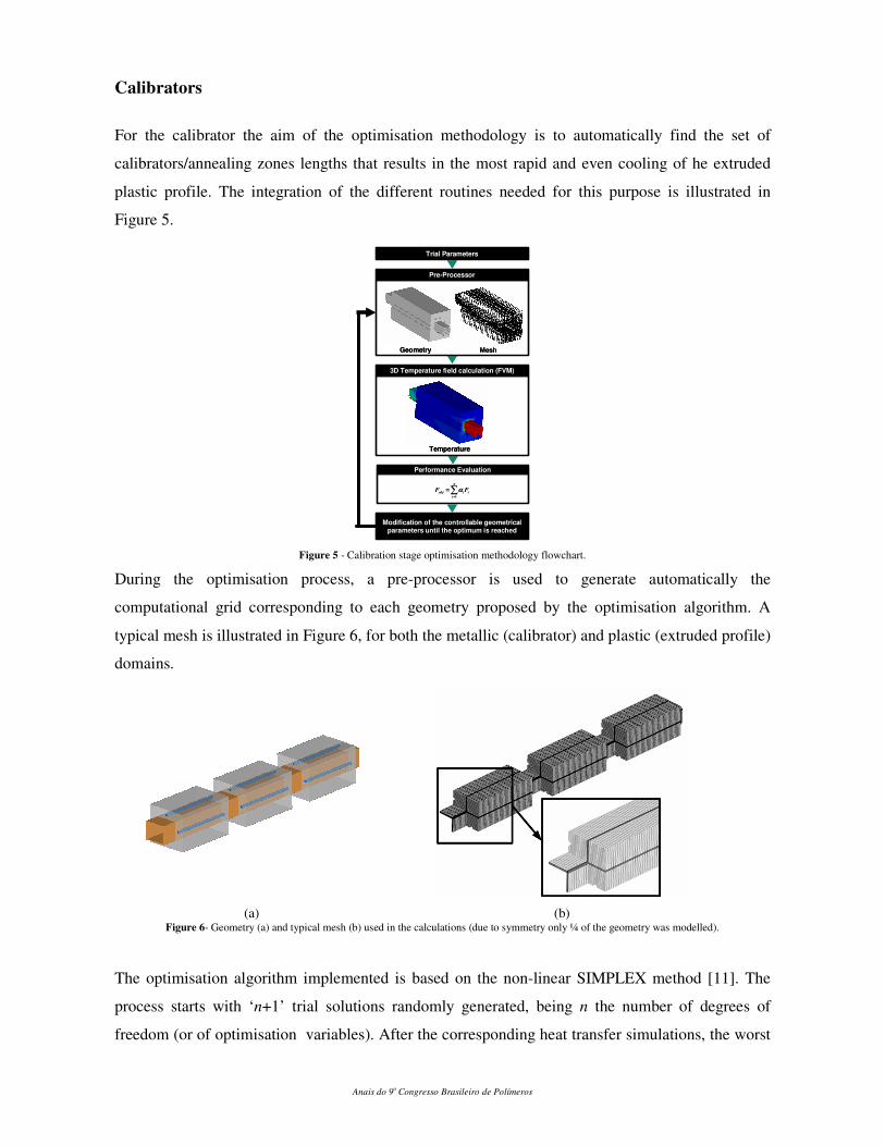
Calibrators
For the calibrator the aim of the optimisation methodology is to automatically find the set of
calibrators/annealing zones lengths that results in the most rapid and even cooling of he extruded
plastic profile. The integration of the different routines needed for this purpose is illustrated in
Figure 5.
Pre-Processor
Geometry Mesh
3D Temperature field calculation (FVM)
Temperature
Trial Parameters
Performance Evaluation
∑=
=
n
i
iiobj FF1
α
Modification of the controllable geometrical parameters until the optimum is reached
Pre-Processor
Geometry Mesh
3D Temperature field calculation (FVM)
Temperature
Trial Parameters
Performance Evaluation
∑=
=
n
i
iiobj FF1
α
Modification of the controllable geometrical parameters until the optimum is reached
Figure 5 - Calibration stage optimisation methodology flowchart.
During the optimisation process, a pre-processor is used to generate automatically the
computational grid corresponding to each geometry proposed by the optimisation algorithm. A
typical mesh is illustrated in Figure 6, for both the metallic (calibrator) and plastic (extruded profile)
domains.
(a) (b) Figure 6- Geometry (a) and typical mesh (b) used in the calculations (due to symmetry only ¼ of the geometry was modelled).
The optimisation algorithm implemented is based on the non-linear SIMPLEX method [11]. The
process starts with ‘n+1’ trial solutions randomly generated, being n the number of degrees of
freedom (or of optimisation variables). After the corresponding heat transfer simulations, the worst
Anais do 9o Congresso Brasileiro de Polímeros
solution is rejected and is replaced by a new trial solution proposed by the algorithm. The
calculation finishes when the standard deviation of the objective function of the set of ‘n+1’
solutions is lower than a prescribed value.
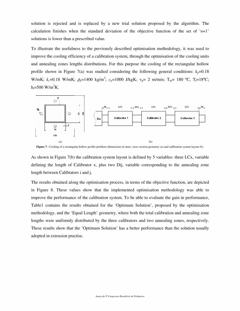
To illustrate the usefulness to the previously described optimisation methodology, it was used to
improve the cooling efficiency of a calibration system, through the optimisation of the cooling units
and annealing zones lengths distributions. For this purpose the cooling of the rectangular hollow
profile shown in Figure 7(a) was studied considering the following general conditions: kp=0.18
W/mK; kc=0.18 W/mK; ρp=1400 kg/m3; cp=1000 J/kgK; vp= 2 m/min; Tm= 180 ºC, Tf=18ºC;
hi=500 W/m2K.
(a) (b)
Figure 7 - Cooling of a rectangular hollow profile problem (dimensions in mm): cross section geometry (a) and calibration system layout (b).
As shown in Figure 7(b) the calibration system layout is defined by 5 variables: three LCx, variable
defining the length of Calibrator x, plus two Dij, variable corresponding to the annealing zone
length between Calibrators i and j.
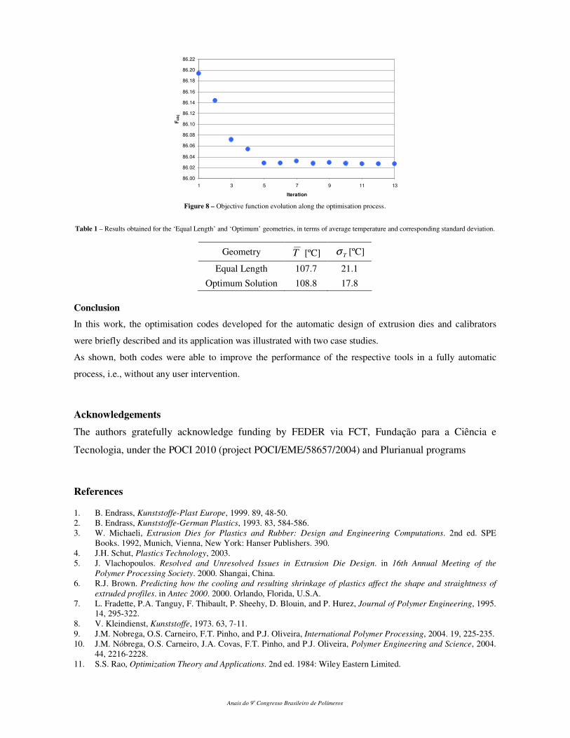
The results obtained along the optimisation process, in terms of the objective function, are depicted
in Figure 8. These values show that the implemented optimisation methodology was able to
improve the performance of the calibration system. To be able to evaluate the gain in performance,
Table1 contains the results obtained for the ‘Optimum Solution’, proposed by the optimisation
methodology, and the ‘Equal Length’ geometry, where both the total calibration and annealing zone
lengths were uniformly distributed by the three calibrators and two annealing zones, respectively.
These results show that the ‘Optimum Solution’ has a better performance than the solution usually
adopted in extrusion practise.
Anais do 9o Congresso Brasileiro de Polímeros
86.00
86.02
86.04
86.06
86.08
86.10
86.12
86.14
86.16
86.18
86.20
86.22
1 3 5 7 9 11 13
Iteration
Fo
bj
Figure 8 – Objective function evolution along the optimisation process.
Table 1 – Results obtained for the ‘Equal Length’ and ‘Optimum’ geometries, in terms of average temperature and corresponding standard deviation.
Geometry T [ºC] Tσ [ºC]
Equal Length 107.7 21.1
Optimum Solution 108.8 17.8
Conclusion
In this work, the optimisation codes developed for the automatic design of extrusion dies and calibrators
were briefly described and its application was illustrated with two case studies.
As shown, both codes were able to improve the performance of the respective tools in a fully automatic
process, i.e., without any user intervention.
Acknowledgements
The authors gratefully acknowledge funding by FEDER via FCT, Fundação para a Ciência e
Tecnologia, under the POCI 2010 (project POCI/EME/58657/2004) and Plurianual programs
References
1. B. Endrass, Kunststoffe-Plast Europe, 1999. 89, 48-50.
2. B. Endrass, Kunststoffe-German Plastics, 1993. 83, 584-586.
3. W. Michaeli, Extrusion Dies for Plastics and Rubber: Design and Engineering Computations. 2nd ed. SPE
Books. 1992, Munich, Vienna, New York: Hanser Publishers. 390.
4. J.H. Schut, Plastics Technology, 2003.
5. J. Vlachopoulos. Resolved and Unresolved Issues in Extrusion Die Design. in 16th Annual Meeting of the
Polymer Processing Society. 2000. Shangai, China.
6. R.J. Brown. Predicting how the cooling and resulting shrinkage of plastics affect the shape and straightness of
extruded profiles. in Antec 2000. 2000. Orlando, Florida, U.S.A.
7. L. Fradette, P.A. Tanguy, F. Thibault, P. Sheehy, D. Blouin, and P. Hurez, Journal of Polymer Engineering, 1995.
14, 295-322.
8. V. Kleindienst, Kunststoffe, 1973. 63, 7-11.
9. J.M. Nobrega, O.S. Carneiro, F.T. Pinho, and P.J. Oliveira, International Polymer Processing, 2004. 19, 225-235.
10. J.M. Nóbrega, O.S. Carneiro, J.A. Covas, F.T. Pinho, and P.J. Oliveira, Polymer Engineering and Science, 2004.
44, 2216-2228.
11. S.S. Rao, Optimization Theory and Applications. 2nd ed. 1984: Wiley Eastern Limited.
Related Documents