1 RECENT CHALLENGES IN DEEP FOUNDATION CONSTRUCTIONS IN THAILAND Narong Thasnanipan, Thayanan Boonyarak, Zaw Zaw Aye, Sereyroath Chea and Chanraksmey Roth Seafco Public Company Limited 144 Prayasuren Road, Klongsamwah, Bangkok, Thailand 10510 e-mail: <[email protected]> webpage: http://www.seafco.co.th Keywords: Deep foundation, Challenges in construction, Thailand Abstract. In recent years, there has been an increase in urban development in Thailand. The development initiated by government sector included roads, railways, mass rapid transit and airports. For private sector, the major development focuses in Bangkok, the capital city. Challenge of construction of these mega projects in Bangkok is very soft and unstable ground conditions. Ground condition in Bangkok consist of soft marine clay with thickness up to 20 m. Problems of foundation in this type of soil consist of large settlement of buildings, instability and damage of structure due to tilting and differential settlement. To tackle these problems, deep foundation such as large diameter bored pile and barrette are adopted to support the structures. In this paper, challenges and major issues relevant to geotechnical problems for the mega projects are highlighted. Solution to each problem encountered is described and explained. Innovation in design and construction to overcome those challenges are discussed. 1 INTRODUCTION Mega projects in Thailand includes large scale infrastructures for public sector and tall buildings for private sector. To support those heavy structures, deep foundation is required. Due to substantial increase in land price in urban area, the required load per pile hs been increased significantly. Those deep foundations and deep excavation works are constructed in very ground conditions that encounter many challenges. The challenges include advancement in construction technique, difficulties in working area, understanding the behavior of very deep foundation, bleeding and channeling in tremie concrete. This paper reports details relevant to the above issues. Solutions to tackle those problems are presented and discussed.

Welcome message from author
This document is posted to help you gain knowledge. Please leave a comment to let me know what you think about it! Share it to your friends and learn new things together.
Transcript

1
RECENT CHALLENGES IN DEEP FOUNDATION
CONSTRUCTIONS IN THAILAND
Narong Thasnanipan, Thayanan Boonyarak, Zaw Zaw Aye,
Sereyroath Chea and Chanraksmey Roth
Seafco Public Company Limited
144 Prayasuren Road, Klongsamwah, Bangkok, Thailand 10510
e-mail: <[email protected]> webpage: http://www.seafco.co.th
Keywords: Deep foundation, Challenges in construction, Thailand
Abstract. In recent years, there has been an increase in urban development in Thailand.
The development initiated by government sector included roads, railways, mass rapid
transit and airports. For private sector, the major development focuses in Bangkok, the
capital city. Challenge of construction of these mega projects in Bangkok is very soft and
unstable ground conditions. Ground condition in Bangkok consist of soft marine clay with
thickness up to 20 m. Problems of foundation in this type of soil consist of large settlement
of buildings, instability and damage of structure due to tilting and differential settlement.
To tackle these problems, deep foundation such as large diameter bored pile and barrette
are adopted to support the structures. In this paper, challenges and major issues relevant
to geotechnical problems for the mega projects are highlighted. Solution to each problem
encountered is described and explained. Innovation in design and construction to overcome
those challenges are discussed.
1 INTRODUCTION
Mega projects in Thailand includes large scale infrastructures for public sector and tall
buildings for private sector. To support those heavy structures, deep foundation is required.
Due to substantial increase in land price in urban area, the required load per pile hs been
increased significantly. Those deep foundations and deep excavation works are constructed
in very ground conditions that encounter many challenges. The challenges include
advancement in construction technique, difficulties in working area, understanding the
behavior of very deep foundation, bleeding and channeling in tremie concrete. This paper
reports details relevant to the above issues. Solutions to tackle those problems are presented
and discussed.

Narong Thasnanipan, Thayanan Boonyarak, Zaw Zaw Aye, Sereyroath Chea and Chanraksmey Roth
2
(b) (a)
2 GENERAL GEOLOGICAL AND GEOTECHNICAL INFORMATION IN
THAILAND
Figure 1a shows Geological map of Thailand (Department of Mineral Resources, 1999).
Major urban development has taken place in Greater Bangkok area, where soil conditions
consist of soft marine deposit at the top 10-20 m follow by alternating layers of sand and
clay. Igneous rocks are mainly located in the North, East and South. The most common
rock encountered during bored pile construction in these regions is granite. Typical
unconfined compressive strength (UCS) of granite from several projects the authors have
collected is ranging from 40-150 MPa. Common rocks in the Northeast are sedimentary
type such as siltstone, sandstone, claystone and shale. These are considered as soft rocks,
having their UCS between 10 and 50 MPa.
Figure 1b shows location of soft marine clay in Southeast Asia (Brand & Premchitt,
1989). In Thailand, soft soil can be found in the Chaopraya Basin where the thickness of
soft clay layer is from 5 to 20 m. The soft clay thick is increasing inversely proportional to
the distance from the Gulf of Thailand. These soft marine clay can also be found in some
part of Southern Thailand.
Figure 1: (a) Geological map of Thailand (Department of Mineral Resources, 1999); (b)
Location of soft marine clay in Southeast Asia (Brand & Premchitt, 1989)
Narong Thasnanipan, Thayanan Boonyarak, Zaw Zaw Aye, Sereyroath Chea and Chanraksmey Roth
3
-
60
-
50
-
40
-
10
Weathered Crust
Medium to
Stiff Clay
Medium
Dense Sand
(First Sand)
Bangkok Soft
Clay
Hard Clay
Dense to Very
Dense Sand
(Second Sand)
0
0 200 400 600
Hyd
rosta
tic Lin
e
Actu
al P
iezo
metric D
raw
dow
n L
ine
Pore Pressure (kN/m2)
0
10
20
30
40
50
De
pth
(m
)
60
-
30
-
20
Su= 10-25 KPa t = 14-16kN/m3
Su= 50-140 KPa t = 17-21kN/m3
SPT-N= 20-40 t = 20kN/m3
Su> 200 KPat = 21KN/m3
SPT-N= 50-100 t = 21KN/m3
GeotechnicalParameters
(a) (b)
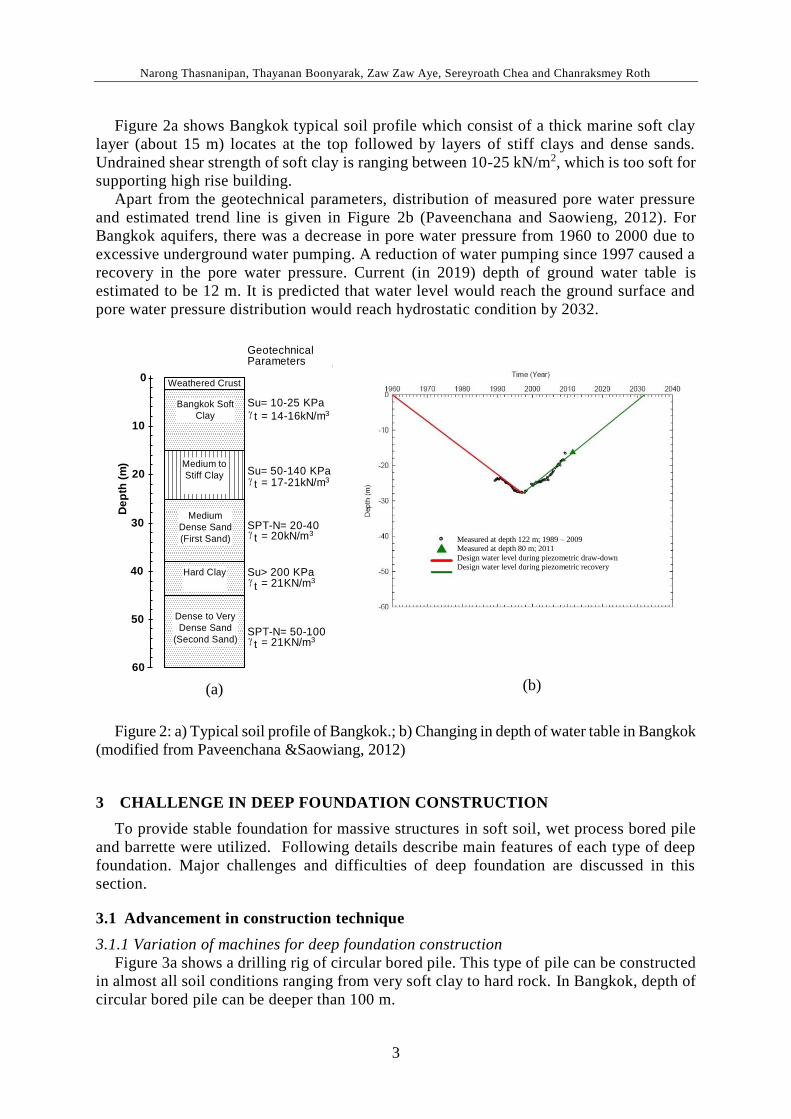
Figure 2a shows Bangkok typical soil profile which consist of a thick marine soft clay
layer (about 15 m) locates at the top followed by layers of stiff clays and dense sands.
Undrained shear strength of soft clay is ranging between 10-25 kN/m2, which is too soft for
supporting high rise building.
Apart from the geotechnical parameters, distribution of measured pore water pressure
and estimated trend line is given in Figure 2b (Paveenchana and Saowieng, 2012). For
Bangkok aquifers, there was a decrease in pore water pressure from 1960 to 2000 due to
excessive underground water pumping. A reduction of water pumping since 1997 caused a
recovery in the pore water pressure. Current (in 2019) depth of ground water table is
estimated to be 12 m. It is predicted that water level would reach the ground surface and
pore water pressure distribution would reach hydrostatic condition by 2032.
Figure 2: a) Typical soil profile of Bangkok.; b) Changing in depth of water table in Bangkok
(modified from Paveenchana &Saowiang, 2012)
3 CHALLENGE IN DEEP FOUNDATION CONSTRUCTION
To provide stable foundation for massive structures in soft soil, wet process bored pile
and barrette were utilized. Following details describe main features of each type of deep
foundation. Major challenges and difficulties of deep foundation are discussed in this
section.
3.1 Advancement in construction technique
3.1.1 Variation of machines for deep foundation construction
Figure 3a shows a drilling rig of circular bored pile. This type of pile can be constructed
in almost all soil conditions ranging from very soft clay to hard rock. In Bangkok, depth of
circular bored pile can be deeper than 100 m.
Measured at depth 122 m; 1989 – 2009 Measured at depth 80 m; 2011
Design water level during piezometric draw-down
Design water level during piezometric recovery

Narong Thasnanipan, Thayanan Boonyarak, Zaw Zaw Aye, Sereyroath Chea and Chanraksmey Roth
4
(a) (b) (c)
In some cases, barrette (rectangular bored pile) is used due to its versatility and larger
load bearing capacity given the same amount of concrete. The equipment of barrette
construction is shown in Figure 3b. For working conditions under limited head room, the
equipment of barrette construction can be shortened and modified as shown in Figure 3c.
This modification provides the advantage of barrette over circular bored pile that cannot
work under the low headroom conditions.
Figure 3: Machine for construction (a) Rotary auger and bucket type; (b) Hydraulic grab
for normal conditions; (c) Mechanical grab for limited headroom conditions.
3.1.2 Shape of deep foundation
For circular bored pile section (as shown in Figure 4a). the advantage is the borehole is
stable during excavation due to hoop stress effects. The rate of construction is faster than
those of barrette piles. Unlike circular bored pile, the lateral load resistance of rectangular
barrette (see Fig. 4b) in the major axis is larger than in the minor axis. Thus, if the lateral
force is majority in one direction, barrette can be a good option for design compared with
bored pile. For a special loading case, T-shape barrette and X-shape barrette as shown in
Figures 4c and 4d, respectively are used to resist large vertical load and lateral load.

Narong Thasnanipan, Thayanan Boonyarak, Zaw Zaw Aye, Sereyroath Chea and Chanraksmey Roth
5
(a) (b) (c) (d)
(a) (b) (c)
Figure 4: Exposed deep foundations; (a) Circular bored pile; (b) Rectangular barrette; T-
shape barrette; (d) X-shape barrette
3.1.3 Installation technique to minimize vibration in bored pile
One of concerns for bored pile construction is vibration in construction. Casing
installation using conventional vibro hammer may cause problems such as disturbance or
damage to neighboring structures. To minimize the vibration in sensitive area, double-
casing method using short-casing and long-casing is adopted as shown in Figure 5. By using
this method vibration can be controlled within the specified limit.
Figure 5: Sequence of double casing installation: a) Install outer casing without using vibro
hammer; b) Install inner casing using vibro hammer; c) Checking verticality of inner casing.

Narong Thasnanipan, Thayanan Boonyarak, Zaw Zaw Aye, Sereyroath Chea and Chanraksmey Roth
6
(a) (b)
3.2 Improvement in quality control and pile testing
Key factors of delivering good quality bored pile are to provide rigorous quality control
and suitable testing method. In-situ test to assess the integrity of each pile for the entire
depth is cross-hole sonic logging test. The principle of testing is to transmit the sonic wave
from one tube to another as shown in Figure 6a. If the concrete integrity is sound, there is
no delay in signal (see Figure 6b). From this example, the concrete quality is good from 0
to 100 m.
Figure 6: a) Layout of sonic logging tubes and b) Example test profiles (3 out of 15).
To understand load transfer behavior, vibrating wire strain gauges (VWSG) are installed at
the major soil boundaries for each pile. The measured data from strain gauge, load distribution
curves along the test pile shaft at various applied load are shown in Figure 7a. The values of
unit skin friction developed by the maximum test load at the different soil layers along the shaft
of test piles in comparison with those of calculated ultimate unit skin friction are also
illustrated. Load distribution curves show that skin friction along pile shaft below 80 m was
not yet fully mobilized at the design load of 3200 T. This load carry proportion can be used to
estimate pile settlement using Tomlinson (1995) method.
The results of load distribution obtained from strain gauges are based on numbers of layers
of the instrument. To measure load distribution continuously, a new method using fiber optics
is adopted. The load transfer results from fiber optics is shown in Figure 7b, which installed in
the same piles as strain gauges (as shown in Figure 7a). The results from both instrument are
in the same trend, suggesting that the new method can be adopted to obtain continuous
measurement.

Narong Thasnanipan, Thayanan Boonyarak, Zaw Zaw Aye, Sereyroath Chea and Chanraksmey Roth
7
(a) (b)
Figure 7: Axial load distribution in a 100 m deep bored pile a) Measured by strain gages; b)
Measured by fiber optics
3.3 Understanding the behavior of very deep foundation
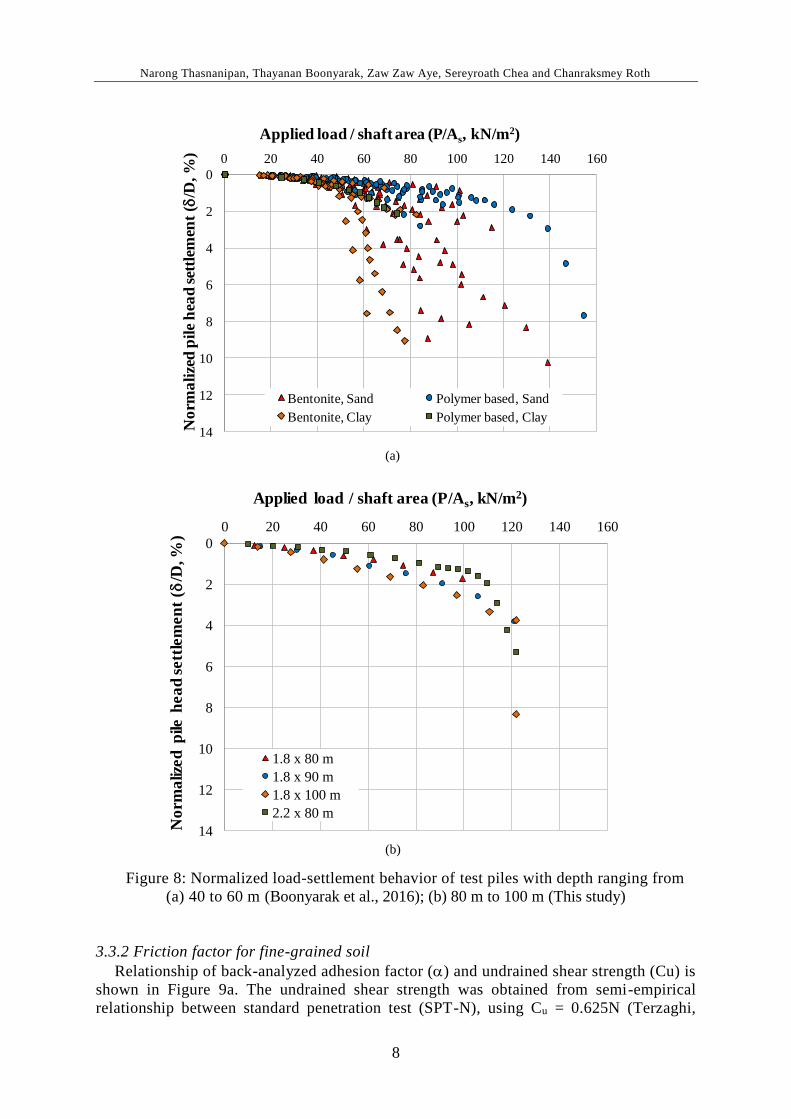
3.3.1 Load settlement behavior
The major issue for design and construction of deep foundation is the understanding of
their behavior. Figures 8a and 8b show load settlement curves of bored pile with depth
ranging from 40 m to 60 m and 80 m to 100 m, respectively. To compare results from piles
with different sizes and depth of pile tip, the applied load is normalized with shaft area and
pile settlement is normalized with its diameter. Factors affecting the behavior of deep
foundation in Bangkok soil including type of drilling slurry, type of foundation, soil type
at the pile tip were analyzed and interpreted. For brevity of paper, details of each factor are
not explained in this paper.
0
10
20
30
40
50
60
70
80
90
100
0 2,000 4,000 6,000 8,000
Dep
th (
m)
Axial Load (ton)
800 Ton
1600 Ton
2400 Ton
3200 Ton
4000 Ton
4800 Ton
5600 Ton
6400 Ton
7040 Ton
Strain ()
50 250 450 650 850
Narong Thasnanipan, Thayanan Boonyarak, Zaw Zaw Aye, Sereyroath Chea and Chanraksmey Roth
8
0
2
4
6
8
10
12
14
0 20 40 60 80 100 120 140 160
Applied load / shaft area (P/As, kN/m2)
Bentonite, Sand Polymer based, Sand
Bentonite, Clay Polymer based, Clay
No
rma
lize
d p
ile
hea
d s
ettl
emen
t (d
/D, %
)
(a)
(b)
0
2
4
6
8
10
12
14
0 20 40 60 80 100 120 140 160
Applied load / shaft area (P/As, kN/m2)
1.8 x 80 m
1.8 x 90 m
1.8 x 100 m
2.2 x 80 m
No
rma
lized
pile
hea
d s
ett
lem
en
t (d
/D, %
)
Figure 8: Normalized load-settlement behavior of test piles with depth ranging from
(a) 40 to 60 m (Boonyarak et al., 2016); (b) 80 m to 100 m (This study)
3.3.2 Friction factor for fine-grained soil
Relationship of back-analyzed adhesion factor () and undrained shear strength (Cu) is
shown in Figure 9a. The undrained shear strength was obtained from semi-empirical
relationship between standard penetration test (SPT-N), using Cu = 0.625N (Terzaghi,

Narong Thasnanipan, Thayanan Boonyarak, Zaw Zaw Aye, Sereyroath Chea and Chanraksmey Roth
9
0.0
0.2
0.4
0.6
0.8
1.0
1.2
0 100 200 300 400
Cu (kN/m2)
Bentonite
Polymer
Pimpasugdi (1979)
FHWA (2010)
NAVFAC (1982)
(a)
1943). There is no major difference of adhesion factor between bored pile constructed using
polymer-based slurry and bentonite slurry. This is because the filtration of both slurries in
fine-grained soil is very small. As a result, no filter cake was formed on the shaft of
borehole. Three approaches to estimate adhesion factor were compared with the measured
results. It can be seen that the three methods still give a reasonable estimation of ,
providing that factor of safety is not less than 1.5 for shaft resistance.
3.3.3 Friction factor in coarse-grained soil
Figure 9b shows back-analyzed friction factor in coarse-grained soil (Ks tan d). Angle
of internal friction was obtained from semi-empirical relationship from SPT-N (Peck et al.,
1974). The results are from bored pile constructed with bentonite slurry and polymer-based
slurry. To back-analyze the parameter, earth pressure coefficient (Ks) of 0.50 and 0.70 were
used as approximation. Angle of pile/soil friction (d') of 0.75 (Kullhawy, 1984) was
adopted. It can be seen that for pile with depth not more than 60 m, the friction factor was
still within Ks of 0.7. However, for piles with tip ranging from 80 m to 100 m, the friction
factor become larger than 0.35. These friction factor was measured from the 2nd sand layer,
that data of pile testing in the past does not fully mobilized. For Ks.tan dsmaller than 0.2,
shaft resistance may not be fully mobilized or thick filter cake may be formed.

Narong Thasnanipan, Thayanan Boonyarak, Zaw Zaw Aye, Sereyroath Chea and Chanraksmey Roth
10
(b)
0.10
0.15
0.20
0.25
0.30
0.35
0.40
0.45
0.50
0.55
30 32 34 36 38 40
Fric
tio
n f
acto
r,b
Angle of internal friction, ' ( )
Bentonite (Boonyarak et al., 2015)
Polymer (Boonyarak et al., 2015)
Bentonite (Submaneewong, 2001)
Pile depth 80-100 m (This study)
0.7 tan (0.75')
0.5 tan (0.75')
2nd sand, this study
1st sand, this study
3rd sand, this
study
not fully
mobilized
Figure 9: Measured friction parameter for pile in soil; a) For clay (); b) For sand (b)
3.3.4 Mobilized shaft friction in rock
Figure 10 shows mobilized unit shaft friction in siltstone layer. Relationship between
unconfined compressive strength of rock (UCS) and unit friction from 0.1 to 0.3 square
root of UCS are used for comparison. Horvath et al. (1983) reported that fully mobilized
friction in rock were from 0.2 to 0.3 square root of UCS. In this paper, mobilized unit skin
friction can be estimated by 0.1 square root UCS line. One of possible reasons to this
observation was shaft movement in siltstone layer was not fully mobilized as maximum
pile head settlement was still less than 1% of the pile diameter. This small shaft movement
resulted in relatively small shaft friction in rock layer compared with those in the literature.

Narong Thasnanipan, Thayanan Boonyarak, Zaw Zaw Aye, Sereyroath Chea and Chanraksmey Roth
11
0.0
0.5
1.0
1.5
2.0
0 5 10 15 20 25 30
Mo
bil
ized
un
it s
kin
fric
tio
n, f
s(M
Pa
)
Unconfined compressive strength of rock (MPa)
. √(UCS)
1√(UCS)
3√(UCS)
Figure 10: Measured unit skin friction in siltstone and sandstone (Aye et el., 2017)
3.4 Enhancing quality of tremie concrete
3.4.1 Typical problem encountered for tremie concrete
Concrete pouring through tremie pipe is one of the most important procedure for deep
foundation. Integrity problem for the hardened concrete was reported to be resulted from
bleeding and channeling of fresh concrete. Evidence of channeling or upward water flow
in fresh concrete is shown in Figure 11a. Records of water flow duration was ranging from
10 to 30 minutes, depends on pile depth. The location of bleeding or channeling was at the
center of the pile, where tremie pipe is placed. When the pile head is exposed (see Figure
11b), unsound and damp concrete was found. To further investigate the concrete quality,
cored samples of concrete were taken as shown in Figure 11c. Evidence of imperfect
concrete was found up to 5 m from the pile cut-off level. If mix design of concrete is
inappropriate or tremie concreting procedures are not well-controlled, weak spot or
channeling may occur. From the literature, fresh concrete with fly ash content of more than
20% and water to binder ratio of more than 0.5 is likely to cause bleeding and channeling.
For bored pile, bleeding may occur around the pile’s reinforcement as shown in Figure
12a. It was found that the water kept flowing upward until polyurethane foam (PU) was
injected to stop the flow. At this interface between fresh concrete and reinforcement, there
may be a gap due to channeling. Thus, bond between reinforcement and concrete can be
substantially decreased. To reduce bleeding, water to binder ratio can be minimized and
concrete gradation can be adjusted. However, flow ability, fill ability and passing ability of
concrete are also key factors for tremie concrete. Figures 12b shows concrete trapped inside
the rebar cage of bored pile. It shows that the rebar clear spacing was too small (less than
100 mm). Thus, to control bleeding, while maintaining the flow ability, viscosity modifier
such as superplasticizer should be used. In addition, maximum size of aggregate for dense
rebar cage should not be larger than 10 mm, not as large as 20 mm for conventional tremie
concrete.

Narong Thasnanipan, Thayanan Boonyarak, Zaw Zaw Aye, Sereyroath Chea and Chanraksmey Roth
12
Upward water flow
Damp concrete
(a) (b)
a) b) c)
Figure 11: a) Water flow up to concrete surface in fresh state; b) Unsound and damp concrete
at pile head; c) Cored samples of unsound concrete. (Thasnanipan et al., 2017)
Figure 12: a) Water upward flow around the rebar of bored pile; b) Effects of dense rebar in
bored pile
3.4.2 Testing method for channeling potential
To tackle bleeding and channeling of very deep bored pile (i.e., depth from 80 m to 100
m) filtration test should be carried out as shown in Figure 13a. This is because the water
pressure from outside the borehole and inside the fresh concrete can be very high. Thus,
water retention ability should be tested. For comparison between normal concrete and
special mix concrete, a standard filtration apparatus for drilling fluid can be used for testing
of fresh concrete (see Figure 13b).

Narong Thasnanipan, Thayanan Boonyarak, Zaw Zaw Aye, Sereyroath Chea and Chanraksmey Roth
13
a) b)
Figure 13: a) Filtration test for concrete (EFFC/DFI, 2018); b) Filtration test for drilling
fluid adopted for fresh concrete.
3.4.3 Proper concrete mix design to minimize bleeding
An example of concrete mix design to minimize bleeding and channeling is given in this
section. A cast-in-situ bored pile with diameter of 1.8 m and depth of 100 m was constructed
as a test pile for a sky scraper in Bangkok. This pile was subjected to vertical compression
static load test up to 70,400 kN. The required compressive strength, slump and initial setting
time of concrete were 45 MPa, 175 mm and 10 hours, respectively. To achieve these
properties, mix design was adjusted as follows. Total binder was 500 kg/cu.m. and
pulverized fly ash content was limited to 20%. Water to binder ratio (W/B) was 0.35 by
adding superplasticizer (Type F admixture). This W/B was lower than typical range of 0.45-
0.48 of normal tremie concrete. Retarder (Type D admixture) was incorporated into the
concrete to prolong the setting time up to 10 hours.
During casting of concrete, no sign of bleeding and channeling was observed. Based on
the result of integrity testing using cross-hole sonic logging, no anomaly was encountered
(refer to Figure 6). Average unconfined compressive strength at 28 days was 63 MPa
(cylinder), exceeding the required strength of 45 MPa.
4 SUMMARY AND CONCLUSIONS
Geotechnical challenges of deep foundation in Thailand are summarized in this paper.
There is a clear trend that foundation is going to be deeper, larger and has higher
performance to support buildings and mega infrastructures with very high load. According
to the given information, following conclusions may be drawn:
Advancement in construction technique: As there is continuous development in
machine and technique, deep foundation can be constructed deeper than 100 m
and in any soil and rock conditions. Quality control can be carried out as
construction progress. This advancement provides better option for engineers and
contractors to arrange the deep foundation in limited construction area.
Deep foundation construction in difficulties in working area: In case of working
under the limited headroom or working on the median of the road, barrette is a
better option over circular bored pile due to its versatility and larger load bearing
capacity. In addition, the machine for barrette construction can be modified to
work under the limited headroom.
Understanding the behavior of very deep foundation: For design and construction
of very deep foundation, interpreted data of pile testing with instrumentation
from previous projects is very useful. Optimization of the design can be carried

Narong Thasnanipan, Thayanan Boonyarak, Zaw Zaw Aye, Sereyroath Chea and Chanraksmey Roth
14
out by testing the pile prior to the working pile to verify the practicality of the
design and to monitor the performance of the contractor.
Bleeding and channeling in tremie concrete: It is found that concrete with fly ash
content of more than 20% and water to binder ratio of more than 0.5 is likely to
cause bleeding and channeling in fresh concrete. Conventional testing method
for bleeding may not be able to capture the bleeding and channeling in deep
foundation. To overcome this limitation, filtration test of concrete should be
carried out to simulate underground water pressure acting on fresh concrete.
5 ACKNOWLEDGEMENT
The Authors would like to acknowledge executives and staff of Seafco Public Company
Limited for supporting of information and suggestions for this paper.
REFERENCES
Aye, Z. Z., Boonyarak, T., Maung, A. W., Thasnanipan, N. and Prongmanee, N. (2015). Back-
analysis of design parameters for bored pile in Yangon. International Conference in Soft
Ground Engineering, Singapore (ICSGE), pp 563-570
Aye, Z. Z., Boonyarak, T., Thasnanipan, N. and Chea, S. (2017). Performance of Large-
Diameter Bored Pile Socketed in Sandstone and Siltstone in Thailand. DFI-PFSF Piled
Foundations & Ground Improvement Technology for the Modern Building and
Infrastructure Sector. 21-22 March 2017, Melbourne, Australia.
Boonyarak, T., Aye, Z. Z., Thasnanipan, N., Supawo, S. and Chea, S. (2016). Settlement
prediction of large-diameter bored pile in Bangkok soils. Proceeding of the sixth
international conference on geotechnique, construction materials and environment
(Geomate 2016), 14-16 November 2016, Bangkok, Thailand.
Brand, E. W. and Premchitt, J. (1989). Comparison of the predicted and observed performance
of the Muar test embankment. Proceeding of the Internation Symposium on Trial
Embankments on Malaysian Marine Clays. Kuala Lumpur Vol 2.
Department of Mineral Resources. (1999). Geological map of Thailand Scale 1:2,500,000.
Ministry of Natural Resources and the Environment. Online http:// www.
mapofthailand.org /geography-map/geological-map-of-thailand/
EFFC/DFI. (2018). Guide to tremie concrete for deep foundations, the joint EFFC/DFI
Concrete Task Group.Online http://www.effc.org/content/ uploads/ 2018/05/EFFC_DFI_
Tremie_ Concrete _ Guide _ 2nd-Edition_ 2018_ Final.pdf
FHWA (U.S. Department of Transportation Federal Highway Administration). (2010). Drilled
Shafts: Construction Procedures and LRFD Design Methods. National Highway Institute
Horvath, R. G., Kenney, T. C. and Kozicki, P. (1983). Method of improving the performance
of drilled piers in weak rock. Canadian Geotechnical Journal, 20, 758-772
Kullhawy, F. H. (1984). “Limiting tip and side resistance, fact or fallacy”, Proc. Symposium
on Analysis and Design of Pile Foundations, American Society of Civil Engineers, San
Francisco, 80-98
NAVFAC (Naval Facilities Engineering Commands). (1986). Design Manual 7.02
Foundations and Earth Structures. Alexandria, Virginia
Paveenchana, T. and Saowiang, K. (2012). The change of piezometric pressure in the subsoil
strata affecting substructures in the Bangkok area. Proc. in Seminar of soil mechanics and
foundation engineering 2012. Engineering Institute of Thailand. Bangkok. p 1-12 (in
Thai).

Narong Thasnanipan, Thayanan Boonyarak, Zaw Zaw Aye, Sereyroath Chea and Chanraksmey Roth
15
Peck, R. B., Hansons, W. E., and Thornburn, T. H. (1974). Foundation Engineering. New York:
John Wiley & Sons
Pimpasugdi, S. (1989). “Performance of Bored, Driven and Auger Press Piles in Bangkok
Subsoils.” Master 's Thesis, GT-88-12, Asian Insitute of Technology, Bangkok
Terzaghi, K. (1943). Theoretical Soil Mechanics. Wiley & Sons, New Jersey.
Thasnanipan, N., Aye, Z. Z. and Boonyarak, T. (2017). Concrete bleeding in bored pile
construction in Bangkok soil. Proceeding of PILE 2017, 26-27 September 2017, Bali,
Indonesia.
Tomlinson M. J. (1995). Foundation Design & Construction. (6th Ed.). Longman Scientific &
Technical, Essex, England
Related Documents