Abstract: 1. Introduction two-wheel two-wheel two- wheel Mobility in outdoor unstructured or semi-structured environments is an important consideration for mobile robotic systems. The intelligence for generating adaptive motor function is important when improving mobility under such an environment. This paper addresses the robot environment interaction of the two-wheel mobile manipulator using a reaction torque observer. We have developed adaptive motor functions of wheel motors for uneven floor surfaces for the two-wheel mobile manipu- lator. Mobile manipulation provides the dual advantage of mobility and dexterity offered by the platform and the manipulator, respectively. The degree of freedom of the platform is also added the redundancy of the system. These systems can be effectively used for a variety of tasks such as industrial robots, service robotics etc. The two-wheel mobile manipulator has the ability to balance on its two-wheels and spin on the spot. This additional maneuverability allows easy navigation on various ter- rains, the turning of sharp corners and making of traverse small steps or curbs. The inverted pendulum problem is one of the common problems in the field of control engineering. The technology that has evolved from this The mobile manipulator has the potential to become an efficient industrial robot due to its mobility and dexterity. Moreover, it has expanded the operational area of the mobile manipulator due to its ability to work in a limited space. However, adaptability to unknown envi- ronments has still not been developed to date. Therefore, adaptation of the mobile manipulator for un- known environments especially for rough/irregular terrain is discussed in this paper. Information about the environ- ment, a key factor when aiming for compliance with an unknown and/or unstructured environment, was collected using a reaction torque observer. In order to adapt to the environment, compliance control was applied to the mobile manipulator. In this paper, we present a novel control strategy we have developed that can deal with unknown environments through the effective use of inverted pendulum control. Simulation and experiments were carried out to ensure the validity of the proposed method. The method could be confirmed as effective according to the results obtained. Keywords: two-wheel mobile manipulator, inverted pendu- lum control, environment interaction, reaction torqueo, compliance control. unstable system is popular among researchers around the world [1],[2]. Consequently, it has been used to imple- ment self-balanced robots by many research groups [3], [4],[5]. The two-wheel mobile manipulator is one of the most recent self-balanced robots in which inverted pen- dulum control has been used [6]. More recently stability improvements have been pro- posed using null space control [7] and control gain swit- ching [8]. However, the two-wheel mobile manipulator is expected to work in a dynamic environment in industry. Therefore this robot should be intelligent enough to cope with an unknown or unstructured environment. This pa- per proposes an embedded motor function, which deve- lops the affinity and adaptability of the two-wheel mo- bile manipulator to the environment. In a real environ- ment, there are different kinds of agents such moving objects, immobile objects and rough surfaces. Detecting the environment is a critical issue in developing intelli- gent motor functions resistant to environmental distur- bances. Researchers have utilized in the recent past dif- ferent kinds of detection methods such as sonar sensors, cameras, sensors with additional memory functions and force sensors [9],[10],[11] etc. Even though many detec- tion methods have been reported on, an enduring prob- lem has been that it is not easy to get precise information about floor due to viscous friction and floor elasticity. However, the reaction torque observer is a good can- didate for obtaining this kind of environmental informa- tion [11]. Hence our choice to use the reaction torque observer to gather information on rough floors as descri- bed in this paper. Another advantage of this system is its low cost implementation due to being a sensor less appli- cation. The robot should be adapted to the environment and this adaptation can be implemented based on the remote and contact information collected. Trajectory tracking and obstacle avoidance derived from positional information are important considerations for adaptation by remote information. Among the significant applica- tions, certain functions can be highlighted, namely: obstacle avoidance and robot navigation using potential functions [13],[14], obstacle avoidance control via sli- ding mode approach [15], near time optimal trajectory planning for wheeled mobile robots [16] and route plan- ning for mobile robots amidst moving obstacles [17]. A versatile controller against environment change has been developed for a power assistant platform [18] and also a wheelchair robot [19] based on contact informa- tion. This paper uses the compliance control as a com- pensation method, which can smoothly compensate the environmental disturbances [20],[25]. Wheel and mani- pulator controllers are combined by means of a virtual CONTROL OF TWO WHEEL MOBILE MANIPULATOR ON A ROUGH TERRAIN USING REACTION TORQUE OBSERVER FEEDBACK Pradeep Kumara W. Abeygunawardhana, Toshiyuki Murakami Received 6 March 2009; accepted 24 September 2009. th th Journal of Automation, Mobile Robotics & Intelligent Systems VOLUME 4, N° 1 2010 Articles 56

Welcome message from author
This document is posted to help you gain knowledge. Please leave a comment to let me know what you think about it! Share it to your friends and learn new things together.
Transcript

Abstract:
1. Introduction
two-wheel
two-wheel
two-wheel
Mobility in outdoor unstructured or semi-structuredenvironments is an important consideration for mobilerobotic systems. The intelligence for generating adaptivemotor function is important when improving mobilityunder such an environment. This paper addresses therobot environment interaction of the two-wheel mobilemanipulator using a reaction torque observer. We havedeveloped adaptive motor functions of wheel motors foruneven floor surfaces for the two-wheel mobile manipu-lator.
Mobile manipulation provides the dual advantage ofmobility and dexterity offered by the platform and themanipulator, respectively. The degree of freedom of theplatform is also added the redundancy of the system.These systems can be effectively used for a variety oftasks such as industrial robots, service robotics etc. Thetwo-wheel mobile manipulator has the ability to balanceon its two-wheels and spin on the spot. This additionalmaneuverability allows easy navigation on various ter-rains, the turning of sharp corners and making of traversesmall steps or curbs. The inverted pendulum problem isone of the common problems in the field of controlengineering. The technology that has evolved from this
The mobile manipulator has the potential tobecome an efficient industrial robot due to its mobility anddexterity. Moreover, it has expanded the operational areaof the mobile manipulator due to its ability to work ina limited space. However, adaptability to unknown envi-ronments has still not been developed to date. Therefore,adaptation of the mobile manipulator for un-known environments especially for rough/irregular terrainis discussed in this paper. Information about the environ-ment, a key factor when aiming for compliance with anunknown and/or unstructured environment, was collectedusing a reaction torque observer. In order to adapt to theenvironment, compliance control was applied to the
mobile manipulator. In this paper, we presenta novel control strategy we have developed that can dealwith unknown environments through the effective use ofinverted pendulum control. Simulation and experimentswere carried out to ensure the validity of the proposedmethod. The method could be confirmed as effectiveaccording to the results obtained.
Keywords: two-wheel mobile manipulator, inverted pendu-lum control, environment interaction, reaction torqueo,compliance control.
unstable system is popular among researchers around theworld [1],[2]. Consequently, it has been used to imple-ment self-balanced robots by many research groups [3],[4],[5]. The two-wheel mobile manipulator is one of themost recent self-balanced robots in which inverted pen-dulum control has been used [6].
More recently stability improvements have been pro-posed using null space control [7] and control gain swit-ching [8]. However, the two-wheel mobile manipulator isexpected to work in a dynamic environment in industry.Therefore this robot should be intelligent enough to copewith an unknown or unstructured environment. This pa-per proposes an embedded motor function, which deve-lops the affinity and adaptability of the two-wheel mo-bile manipulator to the environment. In a real environ-ment, there are different kinds of agents such movingobjects, immobile objects and rough surfaces. Detectingthe environment is a critical issue in developing intelli-gent motor functions resistant to environmental distur-bances. Researchers have utilized in the recent past dif-ferent kinds of detection methods such as sonar sensors,cameras, sensors with additional memory functions andforce sensors [9],[10],[11] etc. Even though many detec-tion methods have been reported on, an enduring prob-lem has been that it is not easy to get precise informationabout floor due to viscous friction and floor elasticity.
However, the reaction torque observer is a good can-didate for obtaining this kind of environmental informa-tion [11]. Hence our choice to use the reaction torqueobserver to gather information on rough floors as descri-bed in this paper. Another advantage of this system is itslow cost implementation due to being a sensor less appli-cation. The robot should be adapted to the environmentand this adaptation can be implemented based on theremote and contact information collected. Trajectorytracking and obstacle avoidance derived from positionalinformation are important considerations for adaptationby remote information. Among the significant applica-tions, certain functions can be highlighted, namely:obstacle avoidance and robot navigation using potentialfunctions [13],[14], obstacle avoidance control via sli-ding mode approach [15], near time optimal trajectoryplanning for wheeled mobile robots [16] and route plan-ning for mobile robots amidst moving obstacles [17].A versatile controller against environment change hasbeen developed for a power assistant platform [18] andalso a wheelchair robot [19] based on contact informa-tion. This paper uses the compliance control as a com-pensation method, which can smoothly compensate theenvironmental disturbances [20],[25]. Wheel and mani-pulator controllers are combined by means of a virtual
CONTROL OF TWO WHEEL MOBILE MANIPULATOR ON A ROUGH
TERRAIN USING REACTION TORQUE OBSERVER FEEDBACK
Pradeep Kumara W. Abeygunawardhana, Toshiyuki Murakami
Received 6 March 2009; accepted 24 September 2009.th th
Journal of Automation, Mobile Robotics & Intelligent Systems VOLUME 4, N° 1 2010
Articles56

inverted pendulum model. Here, balancing of robotshould be accomplished while achieving other motiontargets. No research work has been reported to date re-porting on the use of a reaction torque observer withinverted pendulum control. Therefore, this paper propo-ses an innovative embedded motor function, which candeal with the environment for the two-wheel mobilemanipulator. In summary, this paper presents a controlmethod that compensates the environment. Disturban-ces, which are detected through the reaction torqueobserver, do not affect the inverted pendulum controland trajectory control.
The model for the proposed device is described in thissection. The two-wheel robot has a coaxial two-wheelsystem. A Direct Current (DC) servo motor with an enco-der used to measure wheel angles has been mounted onone wheel. A vehicle body with three link manipulatorsand a wheel system are assembled together. Each mani-pulator link is controlled using a DC servo motor withencoder. The body is connected to the wheel systema passive joint. The angle of the passive joint is measuredusing an inclination sensor. The body connected through
Fig. 1. Two-wheel vehicle.
via
This paper is presented in seven sections. Followingthis introduction section II describes the modeling of therobot. Section III explains the double inverted pendulumand section IV describes the development of a robustwheel controller. Section V presents the manipulatorcontrol and Section VI gives a brief introduction to thedisturbance observer and the reaction torque observer.Section VII has been organized in two parts as thesimulation and the experiment. Each parts gives testprocedure, parameters and results. Finally, we close thepaper with the conclusion.
2. Modeling
Fig. 2. Model of two-wheel mobile robot.
the passive joint, is also assumed to be a manipulatorlink. Therefore, the robot has the form of a two-wheelrobot with four degrees of freedom manipulator.
Mass of the vehicle bodyJoint angle of linkMass of link
Mass of a wheelRotation angle of wheelsDistance between wheel center and center of body
Radius of wheelsUniversal coordinateRobot coordinate
A. DynamicsThe dynamic modeling is described in this section.
The model of the robot is shown in Fig. 2.Variables of this model are given in Table 1.
Inclination angle of the vehicle body
The length of the ith link
In this derivation, we have assumed that mass ofa link is located at the top of the link. is the angle ofthe passive joint and the manipulator works in X-Z plane.X axis is selected horizontally parallel to the floor and Zaxis is selected vertically. and are the robot's co-ordinates. Clockwise rotation of the vehicle body, wheelsand all links are positive. In this model, dynamic equa-tions are formulated using the Lagrange equation of mo-tion. The Lagrange equation is shown in (1).
(1)
is called Lagranrian function and is given by “”. Definitions of parameters are given by (Table 2).
Lagranrian functionKinetic energy of the systemPotential Energy of the systemExternal torques
angles of wheel, passive joint andlinks
Kinetic energy of this system is given by eq. (2)
(2)
(3)
where denotes the linear velocity and representsheight from the wheel center to mass center of the link.
is the moment of inertia of the corresponding links. Bysimplifying (2) and (3) with (1), we can obtain dynamicsof the system as (4).
(4)
Table 1. Dynamic model parameters.
Table 2. Dynamic model parameters.
=1,2,3=1,2,3
�0
mi i
m i im
l
R
z
0
0
0
�
�
�
�
�
�
�
i
i
w
w
i
u
R
R R
i
i
l
x
L L = T -U
LTU
i=w
v h
I
,0,1,2,31,2,3
Journal of Automation, Mobile Robotics & Intelligent Systems VOLUME 4, N° 1 2010
Articles 57

A dynamic equation of the double inverted pendulumis derived by using equation (1) and is given as shownin (10).
Where,is a 3 x 3 symmetric matrix and components are
given in (III). Matrices and are given byequations (11) and (12).
Here is the mass of wheels is the mass of Bodyand is the mass of the second pendulum and it iscalculated as . The dynamics of thedouble inverted pendulum are given in matrix form asexplained by (10)-(12). Assuming that the passive jointangle, and the angle of the second pendulum, aresmall angles, we simplify the second equation of (10).Since is not equal to zero, (13) was obtained. Therelationship between the linear acceleration and the an-gular acceleration of wheels is shown as (14). Stabiliza-tion control of the two-wheeled mobile manipulator wasimplemented using (13) and (14).
In our system, which does not have a control inputis the angle of passive joint. In order to stabilize thewhole system, it is necessary to control . The only waythat can be controlled, is to control the wheel accele-ration. Hence, the control equation (15) is approxi-mated.
is the position gain of wheel command estimationand is the velocity gain of wheel command estima-tion. and are angle and angular velocity of robot
(10)
(11)
(12)
(13)
(14)
(15)
Table 3. Elements .M q
m mM
M m m m
l
K
d
w
d
vd
( )
0
1
1 1 2 3
0
0
0
0
0
= + +
� �
�
�
�
Kpd
where, is the vector of motor torques. is inertiamatrix. represents coriolis acceleration coefficientand centrifugal acceleration coefficient. representsgravity.
Inverted pendulum having two stages is called doubleinverted pendulum. The stability margin of a double in-verted pendulum is larger than that of a single invertedpendulum. The former is used in this paper and a model ofit is shown in Fig. 3.
position of COG (Center Of Gravity)
Angle of second pendulum
In our system, we have three link manipulators andthe robot body. Therefore the manipulator system hasfour degrees of freedom. Equivalent mass center and itsposition for the input into the manipulator system can becalculated for this system as (5) and (6). At this point wehave a virtual robot body and an inverted pendulum.Ultimately it becomes a virtual double inverted pendulumsystem [6]. We used abbreviations to express equations(5) and (6) and those are given in (7).
The length of the second pendulum and the angle ofthe second pendulum are given by equations (8) and (9).
� MH
G
G x
B. Double inverted pendulum
Fig. 3. Double inverted pendulum model.
x
G zl
z
d
d
position of COGLength of second pendulum
(5)
(6)
(7)
(8)
(9)
�
Journal of Automation, Mobile Robotics & Intelligent Systems VOLUME 4, N° 1 2010
m m m Mm M l cosm m M lm M l cosm M l
d w
d d d
d
d d d
d d
11 0 2
13 1
22 0 1 0
31 1
33 1
��� � �
� �
��� �
� �
�
2
2
m m M l cosm m M l cosm M l l cosm M l l cos
d
d
d d d d
d d d d
12 0 1 0 0
21 0 1 0 0
23 1 0 0
32 1 0 0
��� � �
��� � �
� � �� ��
� � �� ��
Articles58

body or passive joint, which are, measured a using gyrosensor. and are command values and equal tozero.
is the interactive effect of the second
pendulum. Equation (15) was substituted with (13) and(14) combined and a Laplace transformation wasperformed for resultant equation. Finally, G(s) can beobtained.
This is a second order transfer function. Natural an-gular frequency, and damping coefficient, are givenin (17). and were selected such that the system isstable. To realize the wheel control, the angular acce-leration of wheel, , which was estimated as describedin (15) was taken as an acceleration command to thewheel motors. Then, estimated angular position and an-gular velocity are generated by integrating the angularacceleration command. The calculation process is repre-sented by (18). Finally, estimated angular position andangular velocity are taken as angular position command,
and angular velocity command, to the wheelmotor as described in (19).
(16)
(17)
(18)
(19)
In rough terrain, there may be some steps and randomitems such as pieces of stone. When the robot collapsesdue to such an item, it is because there have been forcesacting on the wheels of the robot. The controller shouldhave been robust enough to handle these forces. In thissection we explain the implementation of a robustcontroller for rough terrain. List of symbols that we usedin this section is given by Table 4.
Linear position command of the wheelLinear velocity command of the wheelLinear position response of the wheelLinear velocity response of the wheelForce from the environmentEstimated reaction torqueEstimated acceleration of the environmentEstimated velocity of the environmentEstimated position of the environmentPosition gain of wheel controllerVelocity gain of wheel controller
Obviously, the wheel controller is basically a simple
Kpd Kvd
3. Development of robust wheel controllerusing compliance control
Table 4. Wheel controller parameter.
Proportional and Derivative (PD) controller. Angularvelocity command, and angular position commandof wheel, were reckoned using the double invertedpendulum model as described in the previous section.These angular commands can be converted into linearcommands as shown in (20) and (21). Hence, the accele-ration reference of the wheel was drawn as described by(22). and are proportional gain and velocity gain ofwheel controller.
(20)
(21)
(22)
This simple controller was modified by includinga compliance control. Reaction torque estimated throughthe reaction torque observer is used for compliance con-trol. Fig. 4 illustrates the translational and rotationaldirection force components. In this approach the forcecomponent in the rotational direction is zero.
When the wheels of the robot collide with some objecton the floor, it produces forces back on wheels. Theseforces are estimated by reaction torque observers imple-mented on wheel motors as torques. These reaction tor-ques are transformed into the translational direction asexplained in (23).
(23)
Estimated forces are converted into positioncharacteristics using compliance control. If the virtualimpedance characteristics of the environment are ,
and , the conversion of reaction force into theposition command is shown in (24). Aenv is feedback gainof external force.
(24)
Using (24), it is possible to calculate the positionfeedback and velocity feedback from the environment.The acceleration reference command to the wheel motoris modified as shown in (25).
(25)
K K
MD K
p v
env
env env
Fig. 4. Translational and rotational force component of therobot.
Journal of Automation, Mobile Robotics & Intelligent Systems VOLUME 4, N° 1 2010
xvcmd
xvcmd
xvres
xvres
Fenv
Kp
Kv
xenv
xenv
xenv
�reac
.
.
...�
Articles 59

Final acceleration reference value to the wheel motoris implemented as in (25). An acceleration command isproduced by the robust control system based on thedisturbance observer and is transformed into torque bymotor inertia. Here, if only the ingredient of one degreeof freedom is taken out and the
Laplace conversion is carried out, it yields,
(26)
(27)
Where,, - Position response characteristics with respect
to position command ,, - Position response characteristics with respect
to environment force ,, - Compliance characteristics.
By this method, separate designs of characteristics foreach input ( , ) can be obtained. It is possible toattain the desired compliance characteristic , main-taining performance of its position control.
Fig. 5 shows a block diagram of the wheel controller.The control strategy has already been elaborated on;describing how a velocity reference is generated to the
FC
FC
env
env
env
env
wheel motor. The robot presented in this paper iscommanded through a pendulum model. A virtual doubleinverted pendulum model was constructed utilizing mani-pulator dynamics and wheel dynamics. Acceleration com-mands to the wheel are generated using inverted pendu-lum control so that the body can maintain its balancedposition. Desired body angle ( ) is determined by thependulum model according to the commanded COG posi-tion. The inclination sensor that was mounted on therobot body is used to measure the actual angle of the body( ). With the help of this data, an acceleration com-mand is derived and elaborated inside the pendulumcontroller in Fig. 5 and this process was explained bysection 2B.
The angular acceleration command is converted intolinear mode. Velocity and position commands for thewheel motor are calculated by integrating the linear acce-leration command. A reference motor current is calculatedusing motor inertia, gear ratio and current constant.A disturbance observer compensates the disturbances ofthe wheel motor. Reaction torque feedback is used tomodify the trajectory in such a way that the robot canadapt to the changing environment. Reaction torqueobservers are implemented for each wheel motor and theoutputs of those are taken as the input to the compliancecontroller. The strategy that was used to modify the wheelPD controller is depicted in Fig. 5 as a compliance con-troller.
Kinematic relationship can be expressed as shownin (28)-(30). q is the joint angle vector and is defined by
4. Posture control of manipulator usingcog control
Journal of Automation, Mobile Robotics & Intelligent Systems VOLUME 4, N° 1 2010
Fig. 5. Wheel controller with compliance control.
Articles60

Journal of Automation, Mobile Robotics & Intelligent Systems
and is the position vector inworkspace.
(28)
(29)
(30)
where is Jacobean matrix. Position vector inworkspace, becomes COG positions of virtual invertedpendulum. Therefore kinematics represented by isexplained by (31).
(31)
Abbreviations are defined in (7). In the redundantmanipulator, joint space acceleration reference,which was obtained using pseudo inverse matrix, can bewritten as (32). In (32), the first term is the workspaceacceleration and the second term represents the nullspace motion.
(32)
where, is the weighted pseudo inverse matrix anddefined as (33).
(33)
of the above equation is a diagonal weightingmatrix. In the joint space a disturbance observer basedacceleration controller, corresponds with the virtualinertia matrix and can be selected arbitrary [22]. Byusing the joint space and workspace observers in (32), itcan be rewritten as (34) without calculating theand terms [23].
(34)
q x
J qx
f q
W
WI
I J J
=( , , , )
( )
( )
( )
vn
+
The workspace acceleration reference is given in(35).
(35)
where, and are the proportional gain andderivative gain respectively. is the COG position vectorin the workspace of the inverted pendulum and is theCOG position vector in the workspace of the invertedpendulum.
Null space acceleration reference, is calculated asshown in (36). and are angular position commandand angular position response respectively.
(36)
Fig. 6 shows the detailed block diagram of the posturecontrol of the manipulator.
The angular acceleration reference was calcu-lated as shown in (34). Motor inertias were used to derivethe input torques of the manipulator motors. Positionresponses of all links were used to model the virtual inver-ted pendulum. In addition to this, position and velocityresponses were used to calculate the feedback signals tothe workspace. Disturbance observers were implementedto each and every motor.
A workspace observer was constructed to compensatethe workspace error and Fig. 7 illustrates a diagram of it.
K Kx
x
hp hv
cmd
( )
Fig. 7. Block Diagram of workspace observer.
VOLUME 4, N° 1 2010
Fig. 6. Block diagram of manipulator control.
Articles 61
Journal of Automation, Mobile Robotics & Intelligent Systems
Reference acceleration and velocity in the workspaceare the inputs to the workspace observer and is theworkspace gain. is the acceleration reference of theposition vector and is the acceleration error of theposition vector. and are linear velocity responseand angular velocity response respectively.
Disturbance observers were implemented on the motorcontrollers to cancel the disturbance effects [21]. Thissection describes the architecture and characteristics ofa disturbance observer. When a servomotor with onedegree of motion is considered, under an ideal motordriver, a servomotor in the joint space can be representedas (37),
(37)
Where,Generated torque of the motor,Load torque,Motor inertia,Angular acceleration.
The total generated torque can be expressed as
(38)
is a function of flux position and expanded inFourier series and is called a torque coefficient. is tor-que current. In most cases, it is possible to regard astorque current reference .
(39)
Where, is the interactive torque including the Coriolisterm, the centrifugal term and gravity term. is thereaction torque when the mechanical system does theforce task. and are Coulomb and viscous friction,respectively. Substituting (38) and (39) into (37) yields(40).
(40)
The parameters in (40) are the inertia and the torquecoefficient. The inertia will change according to themechanical configuration of the motion system.
(41)
The torque coefficient will vary according to the rotorposition of the electric motor due to irregular distributionof magnetic flux on the surface of rotor.
(42)
Total disturbance torque can be defined as follows.
g
KI
II
F
w
t
a
a
a
5. Disturbance observer, reaction torqueobserver and compliance control
A. Disturbance Observer
ref
(43)
and are the nominal torque coefficient and theinertia, respectively. and are torque coefficientfluctuation and inertia fluctuation respectively. However,dynamic equation yields,
(44)
Rearranging (44), equation (45) can be obtained.Therefore disturbance torque can be obtained as (46).
(45)
(46)
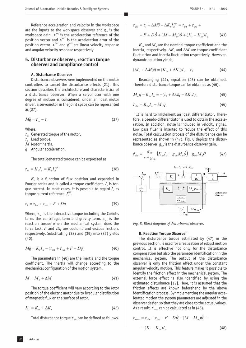
It is hard to implement an ideal differentiator. There-fore, a pseudo-differentiator is used to obtain the accele-ration. In addition, noise is included in velocity signal.Low pass filler is inserted to reduce the effect of thisnoise. Total calculation process of the disturbance can berepresented as shown in (47). Fig. 8 depicts the distur-bance observer. is the disturbance observer gain.
(47)
The disturbance torque estimated by (47) in theprevious section, is used for a realization of robust motioncontrol. It is effective not only for the disturbancecompensation but also the parameter identification in themechanical system. The output of the disturbanceobserver is only the friction effect under the constantangular velocity motion. This feature makes it possible toidentify the friction effect in the mechanical system. Theexternal force effect is also identified by using theestimated disturbance [12]. Here, it is assumed that thefriction effects are known beforehand by the aboveidentification process. By implementing the angular acce-lerated motion the system parameters are adjusted in theobserver design so that they are close to the actual values.As a result, can be calculated as in (48).
(48)
K MK M
g
tn n
t
ob
� �
Fig. 8. Block diagram of disturbance observer.
B. Reaction Torque Observer
VOLUME 4, N° 1 2010
Articles62

Journal of Automation, Mobile Robotics & Intelligent Systems
Reaction torque,Interactive torque,Coulomb friction,Viscous friction,Nominal value of motor inertia,Nominal value of current coefficient,Estimated reaction torque.
Here, it is assumed that the nominal values of Mn and Ktnhave been finely adjusted such that it is almost equal tothe actual values. Total calculation process of reactiontorque observer is shown in (49).
(49)
Fig. (9) depicts the reaction torque observer.
The compliance control is the control system of com-pensating trajectory so that external force may be follo-wed, when force is received from the external world. It ispossible to realize stable contact with the environment bythis, and it becomes possible to give the robot flexibility[19],[20]. Virtual impedance characteristics are set asa mass damper-spring model. If the virtual impedancecharacteristics are , , and force feedback gain is
, Equation (50) explains the conversion of force com-mand into position command, . and are accelera-tion command and velocity command of the compliancecontroller.
(50)
F
MK
M D KA
n
tn
C C C
C
Fig. 9. Block diagram of reaction torque observer.
Fig. 10. Block diagram of compliance control.
C. Compliance Control
The compliance control based position control systemis implemented by applying disturbance observer. Equa-tion (51) and Fig. 10 is explained compliance controlbased position control system.
(51)
In order to verify the proposed method simulation andexperiment was conducted. First, we explain the simula-tion method and its result. Then experiment and resultsare described.
Simulation was carried out to check the validity ofproposed method. Spring-damping model used to modelthe environment [26]. Environment was modeled by usingspring damper model and modeling is explained by (52).
and are damping coefficient and viscous damper ofdamping model, respectively.
(52)
(53)
OpenGL simulation set up was used and it is shown inFig. 11. Simulation parameters are given in table (V).
Symbol Value Symbol Value6000.0 600.010.0 1.00.0001
In simulation, we injected the force to the wheel con-troller during 4.5 seconds and 5 seconds. Physical mea-ning of this is, wheel collides an object on the floor after4.5 seconds and goes over that objects for 0.5 seconds.
6. Validation of proposed method
A. Simulation
K De e
Table 5. Simulation parameter.
Fig. 11. Simulation setup.
VOLUME 4, N° 1 2010
Articles 63

Journal of Automation, Mobile Robotics & Intelligent Systems
Then we observed the resultant torque from the dampingmodel and proposed reaction torque observer and resultsare shown in Fig. 12. Fig. 13 clarifies that there is a torqueriffle when colliding and releasing an object. Variation ofpassive joint angle is shown in Fig. 14 and variation ofCOG positions are shown in Fig. 15 and Fig. 16. Simulationresults are proved that the proposed controller is strongenough to stabilize the system quickly.
An experiment was conducted to check the validity ofthe proposed method using the two-wheel mobile mani-pulator, which is shown in Fig. 1. Before the experimentitself, a constant velocity test was carried out to estimatethe reaction torque. Reaction torque was estimated by
Fig. 12. Torques from the environment.
Fig. 13. Wheel motor torque.
Fig. 14. Angle of passive joint.
B. Experiment
utilizing disturbance torque, which is measured throughthe disturbance observer. According to the definition,terms of gravity and friction effect should be removedfrom disturbance torque to calculate the reaction torque.By performing several constant velocity tests, the gravityand friction effect can be estimated [12]. Therefore,a constant velocity test was carried out for the wheelmotors. Equation (54) shows the equation of frictioneffect. In this case the gravity effect is relatively small.
(54)
Thereafter, the experiment was carried out in an envi-ronment with an irregular floor. Since the laboratory flooris a smooth surface, it was made rough by laying floorcarpets as shown in Fig. 17.
Fig. 15. X position of the pendulum.
Fig. 16. Z position of the pendulum.
Fig. 17. Experiment set up.
VOLUME 4, N° 1 2010
Articles64

Journal of Automation, Mobile Robotics & Intelligent Systems
Initially the robot was moved on a straight-line trajec-tory without the proposed environmental interactionmethod. It failed to deal with this successfully. The-reafter, the proposed compliance control based PD con-troller was applied to the robot wheels and the experi-ment was repeated for same trajectory. The robot movedsuccessfully over the rough floor this time and the datawas collected. Robot details are shown in Table 6 andexperimental parameters are given in Table 7 with thedescriptions.
Description Mass kg Description Length mMass of a wheel 8.5 Radius 0.2Mass of the body 13.0 Length of the link 0 0.125Mass of the link 1 1.06 Length of the link 1 0.2Mass of the link 2 0.84 Length of the link 2 0.2Mass of the link 3 0.5 Length of the link 3 0.18
In our experimental work without the proposed me-thod only the conventional PD control was used for wheelcontrol. Then we applied the controller modified usingcompliance control. The two-wheel mobile manipulator isa self-balancing robot, which does not have any suppor-tive wheels or castors. Therefore it is likely to become uns-table even when submitted to small disturbances from theenvironment. Therefore we used two floor carpets, whichwere not very thick. With only conventional PD control,the robot failed to get over the carpets. However with themodified controller the experiment succeeded and therobot was able to move over carpets.
The inclination angle of the body is depicted by Fig.18. When the robot passed over the step on the floor, theinclination angle increased slightly. However, after pas-sing the barrier, our proposed controller reduced the in-clination angle variation back to its normal.
Table 6. Robot parameter used in experiment.
Table 7. Experimental parameter.
Fig. 18. Inclination angle (passive joint).
Fig. 19 depicts torque variation of the wheel motor.It is clear that torque has been increased at the barriers.However, the controller was strong enough to stabilizethe motor torque. Fig. 20 shows the position variation ofthe two-wheel mobile robot over time. Until body balancewas achieved, the robot did not move forward. Afterachieving the balancing of the body, the robot started tomove forward. While moving, it went over the carpets thathad been laid.
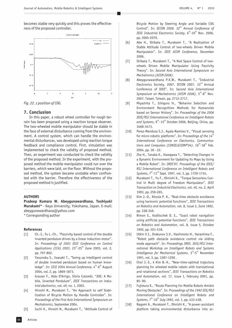
Fig. 21 and Fig. 22 illustrate the COG positions of thevirtual inverted pendulum. Dot lines are the commandvalues in both cases. COG response shows a small amountof variation when going over the floor barrier. However, it
Fig. 19. Reaction torque from environment.
Fig. 20. Position response of robot.
Fig. 21. x position of COG.
VOLUME 4, N° 1 2010
SymbolKKg
p
hv
ob
Value900.060.030.05.0
SymbolKKg
v
pd
w
Value60.010.560.01.0
SymbolKKg
hp
vd
reac
Value900.027.230.0
0.00005
Articles 65
Journal of Automation, Mobile Robotics & Intelligent Systems
becomes stable very quickly and this proves the effective-ness of the proposed controller.
In this paper, a robust wheel controller for rough ter-rain has been proposed using a reaction torque observer.The two-wheeled mobile manipulator should be stable inthe face of external disturbance coming from the environ-ment. A control system, which can handle the environ-mental disturbances, was developed using reaction torquefeedback and compliance control. First, simulation wasimplemented to check the validity of proposed method.Then, an experiment was conducted to check the validityof the proposed method. In the experiment, with the pro-posed method the mobile manipulator could run over thebarriers, which were laid, on the floor. Without the propo-sed method, the system became unstable when confron-ted with the barrier. Therefore the effectiveness of theproposed method is justified.
- Keyo University, Yokohama, Japan. E-mail:[email protected]* Corresponding author
Fig. 22. z position of COG.
7. Conclusion
AUTHORSPradeep Kumara W. Abeygunawardhana, ToshiyukiMurakami*
References[1] Ch.-I., Fu L.-Ch., “Passivity based control of the double
inverted pendulum driven by a linear induction motor”.In:
, 23 -25 June 2003, vol. 2,pp. 797-802.
[2] Yasunobu S., Iwasaki T., “Swing up intelligent controlof double inverted pendulum based on human know-ledge”. In: , 4 -6 August2004, vol. 2, pp. 1869-1873.
[3] Grasser F., Aldo D’Arrigo, Silvio Colombi, “JOE: A Mo-bile, Inverted Pendulum”,
, vol. 49, no. 1, 2002.[4] Hiroshi N., Murakami T., “An Approach to self Stabi-
lization of Bicycle Motion by Handle Controller”. In:
, September 2004.[5] Iuchi K., Hiroshi N., Murakami T., “Attitude Control of
Proceedings of 2003 IEEE Conference on ControlApplications (CCA) 2003
SICE 2004 Annual Conference
IEEE Transactions on indus-trial electronics
Proceedings of the First Asia International Symposium onMechatronics
rd th
th th
Bicycle Motion by Steering Angle and Variable COGControl”. In: I
, 6 -10 Nov. 2006,pp. 2065-2070.
[6] Abe H., Shibata T., Murakami T., “A Realization ofStable Attitude Control of two-wheels Driven MobileManipulator”. In: , December2006.
[7] Shibata T., Murakami T., “A Null Space Control of two-wheels Driven Mobile Manipulator Using PassivityTheory”. In:
.[8] Abeygunawardhana P.K.W., Murakami T., “Industrial
Electronics Society, 2007. IECON 2007. 33 AnnualConference of IEEE”. In:
, 5 -8 Nov.2007, Taipei, Taiwan, pp. 2712-2717.
[9] Miyashita T., Ishiguro H., “Behavior Selection andEnvironment Recognition Methods for Humanoidsbased on Sensor History”. In:
, 9 –15 October 2006, Beijing, China, pp.3468-3473.
[10] Perez-Mendoza S.J., Ayala-Ramirez V., “Visual servoingfor micro robotic platforms”. In:
, 16 -18 Feb.2004, pp. 18 – 22.
[11] Zha H., Tanaka K., Hasegawa T., “Detecting Changes ina Dynamic Environment for Updating its Maps by Usinga Mobile Robot”. In:
, 7 -11 Sept. 1997, vol. 3, pp. 1729-1734.[12] Murakami T., Yu F., Ohnishi K., “Torque Sensorless Con-
trol in Multi degree of Freedom Manipulator”,, vol. 40, no. 2, April
1993, pp. 259-265.[13] Kim J.-O., Khosla P. K., “Real-time obstacle avoidance
using harmonic potential functions”,, vol. 8, issue 3, June 1992,
pp. 338-349.[14] Rimon E., Koditschek D. E., “Exact robot navigation
using artificial potential functions”,, vol. 8, issue 5, October
1992, pp. 501-518.[15] Utkin V.I., Drakunov S.V., Hashimoto H., Harashima F.,
“Robot path obstacle avoidance control via slidingmode approach”. In:
, 3 -5 November1991, vol. 3, pp. 1287-1290 .
[16] Choi J.-S., k Kim B.-K., “Near-time-optimal trajectoryplanning for wheeled mobile robots with translationaland rotational sections”,
, vol. 17, issue 1, February 2001, pp.85- 90.
[17] Fujimura K., “Route Planning For Mobile Robots AmidstMoving Obstacles”. In:
, 7 -10 July 1992, vol. 1, pp. 433-438.[18] Nagami A., Murakami T., Ohnishi K., “A power-assistant
platform taking environmental disturbance into ac-
ECON 2006. 32 Annual Conference ofIEEE Industrial Electronics Society
IEEE AISM Conference
Second Asia International Symposium onMechatronics (AISM 2006)
Second Asia InternationalSymposium on Mechatronics (AISM 2006)
Proceedings of the 2006IEEE/RSJ International Conference on Intelligent Robotsand Systems
Proceedings of the 14International Conference on Electronics, Communica-tions and Computers (CONIELECOMP’04)
IROS’97. Proceedings of the IEEE/RSJ International Conference on Intelligent Robots andSystems
IEEETransaction on Industrial Electronics
IEEE Transactionson Robotics and Automation
IEEE Transactionson Robotics and Automation
Proceedings IROS. IEEE/RSJ Inter-national Workshop on Intelligent Robots and SystemsIntelligence for Mechanical Systems
IEEE Transactions on Roboticsand Automation
Proceedings of the 1992 EEE/RSJInternational Conference on Intelligent Robots andSystems
nd
th
th th
nd
th th
th th
th th
th th
rd th
th th
VOLUME 4, N° 1 2010
Articles66

Journal of Automation, Mobile Robotics & Intelligent Systems
count”. In:, 2000, pp. 152-157.
[19] Katsura S., Ohnishi K., “Human Interaction by a Wheel-chair”. In:
, vol., 5 -8 Nov. 2002, pp.2758-2763.
[20] Katsura S., Ohnishi K., “A Wheelchair type mobile robotTaking Environment Disturbance into Account”, In:
,3 -5 July 2002, pp. 500-505.
[21] Kouhei O., Murakami T., Masaaki S., “Motion control forAdvanced Mechatronics”,
, vol. 1, no. 1, March 1996, pp. 56-67.[22] Oda N., Murakami T., Ohnishi K., “A force based motion
control strategy for hyper-redundant manipulator”. In:
, 9 -14 Nov.1997, vol. 3, pp. 1385-1390.
[23] Murakami T., Kahlen K., De Doncker R.W.A.A., “Robustmotion control based on projection plane in redundantmanipulator”,
, vol. 49, issue 1, February. 2002, pp. 248-225.[24] Abeygunawardhana P.K.W., Murakami T., “Environ-
mental Interaction of two-wheel Mobile Manipulatorusing Reaction Torque Observer”. In:
, 26 – 28 March 2008.[25] Huang Q., Chen X.D., Oka K., “Phased Compliance Con-
trol with Virtual Force for Six Legged Robot”,
, vol. 4, issue: 12, December 2008, pp. 3359-3373.
[26] Morisawa M., Kouhei O., “”, PhD Dissertation, 2003, pp. 45-46.
Proceedings of the 6 International Workshopon Advanced Motion Control
IECON’02. Industrial Electronics Society, IEEE28 Annual Conference
7 International Workshop on Advanced Motion Control
IEEE/ASME Transactions onMechatronics
IECON‘97. 23 International Conference on IndustrialElectronics, Control and Instrumentation
IEEE Transactions on Industrial Electro-nics
Proceedings of the2008 IEEE International Conference on Advance MotionControl. AMC’08
Interna-tional Journal of Innovative Computing Information andControl
Parallel Link Biped RobotMotion Control
th
th
th
rd
th th
rd th
th th
th th
VOLUME 4, N° 1 2010
Articles 67
Related Documents


