Realistic loophole-free Bell test with atom-photon entanglement C. Teo 1 , M. Araújo 2,5 , M. T. Quintino 2,6 , J. Minář 1 , D. Cavalcanti 1,7 , V. Scarani *1,3 , M. Terra Cunha 4 , and M. França Santos † 2 1 Centre for Quantum Technologies, National University of Singapore, Singapore 2 Departamento de Física, Universidade Federal de Minas Gerais, Caixa Postal 702, 30123-970 Belo Horizonte, MG, Brazil 3 Department of Physics, National University of Singapore, Singapore 4 Departamento de Matemática, Universidade Federal de Minas Gerais, Caixa Postal 702, 30123-970 Belo Horizonte, MG, Brazil 5 Faculty of Physics, University of Vienna, Boltzmanngasse 5, 1090 Vienna, Austria 6 Département de Physique Théorique, Université de Genève, 1211 Genève, Switzerland 7 ICFO-Institut de Ciencies Fotoniques, 08860 Castelldefels (Barcelona), Spain Tuesday 7 th January, 2014 Abstract The establishment of nonlocal correlations, guaranteed through the violation of a Bell inequality, is not only important from a fundamental point of view, but constitutes the basis for device-independent quantum information technologies. Although several nonlocality tests have been performed so far, all of them suffered from either the locality or the de- tection loopholes. Among the proposals to overcome these problems are the use of atom-photon entanglement and hybrid photonic measurements (eg. photo-detection and homodyning). Recent studies have suggested that the use of atom-photon entanglement can lead to Bell inequality vi- olations with moderate transmission and detection efficiencies. Here we combine these ideas and propose an experimental setup realizing a sim- ple atom-photon entangled state that can be used to obtain nonlocality when considering realistic experimental parameters including detection efficiencies and losses due to required propagation distances. * Electronic address: [email protected] † Electronic address: msantos@fisica.ufmg.br 1 arXiv:1206.0074v2 [quant-ph] 22 May 2013

Welcome message from author
This document is posted to help you gain knowledge. Please leave a comment to let me know what you think about it! Share it to your friends and learn new things together.
Transcript
Realistic loophole-free Bell test with atom-photonentanglement
C. Teo1, M. Araújo2,5, M. T. Quintino2,6, J. Minář1, D.Cavalcanti1,7, V. Scarani∗1,3, M. Terra Cunha4, and M. França
Santos†2
1Centre for Quantum Technologies, National University of Singapore, Singapore2Departamento de Física, Universidade Federal de Minas Gerais, Caixa Postal 702,
30123-970 Belo Horizonte, MG, Brazil3Department of Physics, National University of Singapore, Singapore
4Departamento de Matemática, Universidade Federal de Minas Gerais, Caixa Postal702, 30123-970 Belo Horizonte, MG, Brazil
5Faculty of Physics, University of Vienna, Boltzmanngasse 5, 1090 Vienna, Austria6Département de Physique Théorique, Université de Genève, 1211 Genève,
Switzerland7ICFO-Institut de Ciencies Fotoniques, 08860 Castelldefels (Barcelona), Spain
Tuesday 7th January, 2014
AbstractThe establishment of nonlocal correlations, guaranteed through the
violation of a Bell inequality, is not only important from a fundamentalpoint of view, but constitutes the basis for device-independent quantuminformation technologies. Although several nonlocality tests have beenperformed so far, all of them suffered from either the locality or the de-tection loopholes. Among the proposals to overcome these problems arethe use of atom-photon entanglement and hybrid photonic measurements(eg. photo-detection and homodyning). Recent studies have suggestedthat the use of atom-photon entanglement can lead to Bell inequality vi-olations with moderate transmission and detection efficiencies. Here wecombine these ideas and propose an experimental setup realizing a sim-ple atom-photon entangled state that can be used to obtain nonlocalitywhen considering realistic experimental parameters including detectionefficiencies and losses due to required propagation distances.
∗Electronic address: [email protected]†Electronic address: [email protected]
1
arX
iv:1
206.
0074
v2 [
quan
t-ph
] 2
2 M
ay 2
013
IntroductionIn recent years several applications of quantum nonlocality have been proposed[1, 2, 3, 4] (see a recent review on Bell nonlocality [5]). These proposals are basedon the fact that nonlocal correlations can be certified without any assumptionon the internal mechanisms of the devices used in the experiment. Thus, onceestablished, nonlocal correlations can be used in what is now referred as, device-independent protocols.
Nonlocal correlations can be obtained by measuring entangled quantum sys-tems in appropriately chosen local observables. This is called a Bell test sincethe nonlocal nature of the measurement outcomes can be certified by the viola-tion of certain constraints known as Bell inequalities [5]. Many Bell tests havebeen performed in the last few decades, but no nonlocal correlations have beenstrictly established so far. This is because all of the performed experimentssuffered either from the detection loophole or the locality loophole [5].
Experiments using entangled photons have reported Bell inequality viola-tions closing separetly the locality [6, 7, 8] and the detection [9] loopholes. Onthe other hand, the detection loophole has been closed with stationary systemslike atoms, ions and circuits [10, 11, 12]. The main technological challengeto close both loopholes simultaneously is to have both efficient detection long-distance entanglement.
In this work, we propose an experimental setup involving available technol-ogy to implement a loophole-free Bell test. It uses a single atom coupled to thefield of a cavity in order to produce a specific entangled state between the atomand the light emitted by the cavity and combines efficient detection schemeson the atomic side and the coherent nature of the light field to perform hybriddetection on the photonic side [13, 14]. Our scheme considers experimental ef-fects neglected in previous proposals [15, 16] and thus puts current atom-photonsystems as good candidates to demonstrate loophole-free nonlocal correlations
The paper is structured as follows: first, we introduce the target state andthe measurement settings used in the Bell test. We then give an explanation ofhow this state can be produced by means of cavity quantum electrodynamics(QED) techniques and discuss the relevant and feasible parameter regime whichyields the desired state. We also discuss an implementation of our scheme in op-tical cavities, and optimize the Clauser-Horne-Shimony-Holt (CHSH) inequality[17] violation for currently available experimental parameters. Finally, we dis-cuss possible circuit QED implementations in the final section and compare ourproposal to previous ones.
ResultsThe ideal caseOur proposal takes advantage of two facts first noticed in [18] and [19]. First,highly efficient detections are typically available for the electronic levels of single
2
atoms [20]. At the same time, photons propagating either in free space or inlow loss optical fibers are excellent candidates for carriers of information overlong distances. Furthermore, the combination of high efficient homodyne detec-tion with photodetection greatly reduces the required minimum photodetectionefficiency [13, 14, 15, 16, 21].
Our starting point is to consider a state of the form
|ψα〉 = cos ν|s, 0〉+ sin ν|g, α〉, (1)
where |g〉, |s〉 are two atomic states and |0〉 and |α〉 denote states of the electro-magnetic field (vacuum and a coherent state respectively) with
|α〉 := e−|α|2
2
∞∑n=0
αn√n!|n〉, (2)
where |n〉 are the energy eigenstates of the field. As we are going to see, this stateviolates a Bell inequality even for low efficiency photodetection and can be wellapproximated with current technology. Although we motivated this work byconsidering a real atom, the state (1) can be in principle devised using differentplatforms, e.g., superconducting qubits, quantum dots, nitrogen-vacancy centerand equivalent systems. We consider the CHSH Bell inequality [17] which statesthat the correlations obtained are nonlocal if the following inequality is violated:
〈B〉 = Tr(ρB) ≤ 2, (3)
where ρ is the quantum state under scrutiny and B denotes the Bell operator
B = A0 ⊗B0 +A0 ⊗B1 +A1 ⊗B0 −A1 ⊗B1, (4)
with Ai and Bj being observables with outcomes ±1. Here, we set the atomicobservables as
A0 = cos γσz + sin γσx, A1 = cos γσz − sin γσx, (5)
where σi are the usual Pauli matrices. In the photonic part we consider di-chotomized photodetection andX quadrature operators (homodyne detection)[13,14]:
B0 = 2 |0〉〈0| − 11, B1 = 2∫ b
−bdx |x〉〈x| − 11, (6)
where |x〉 is the eigenstate of the quadrature operator X = a+a†√2 , and a is the
annihilation operator of the field.Since quadrature measurements can be made very efficient (nearly perfect),
there will be an asymmetry in the total efficiency of the photonic measurements:the total homodyning efficiency will be basically determined by transmissionlosses, while the total photodetection efficiency will be composed by transmis-sion and typical photodetector efficiency. We thus model the transmission losses
3
0 0.2 0.4 0.6 0.8 10.5
0.6
0.7
0.8
0.9
1 A
B
C
D
η
|t lin
e|2
η|tline|2 = 2/3Ref. [16]|ψα〉
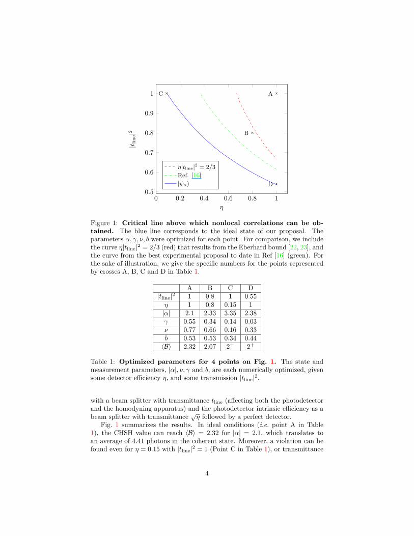
Figure 1: Critical line above which nonlocal correlations can be ob-tained. The blue line corresponds to the ideal state of our proposal. Theparameters α, γ, ν, b were optimized for each point. For comparison, we includethe curve η|tline|2 = 2/3 (red) that results from the Eberhard bound [22, 23], andthe curve from the best experimental proposal to date in Ref [16] (green). Forthe sake of illustration, we give the specific numbers for the points representedby crosses A, B, C and D in Table 1.
A B C D|tline|2 1 0.8 1 0.55η 1 0.8 0.15 1|α| 2.1 2.33 3.35 2.38γ 0.55 0.34 0.14 0.03ν 0.77 0.66 0.16 0.33b 0.53 0.53 0.34 0.44〈B〉 2.32 2.07 2+ 2+
Table 1: Optimized parameters for 4 points on Fig. 1. The state andmeasurement parameters, |α|, ν, γ and b, are each numerically optimized, givensome detector efficiency η, and some transmission |tline|2.
with a beam splitter with transmittance tline (affecting both the photodetectorand the homodyning apparatus) and the photodetector intrinsic efficiency as abeam splitter with transmittance √η followed by a perfect detector.
Fig. 1 summarizes the results. In ideal conditions (i.e. point A in Table1), the CHSH value can reach 〈B〉 = 2.32 for |α| = 2.1, which translates toan average of 4.41 photons in the coherent state. Moreover, a violation can befound even for η = 0.15 with |tline|2 = 1 (Point C in Table 1), or transmittance
4
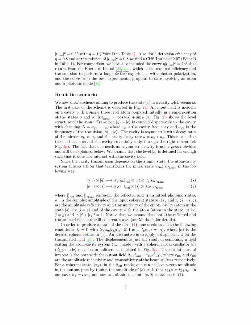
|tline|2 = 0.55 with η = 1 (Point D in Table 1). Also, for a detection efficiency ofη = 0.8 and a transmission of |tline|2 = 0.8 we find a CHSH value of 2.07 (Point Bin Table 1). For comparison, we have also included the curve η|tline|2 = 2/3 thatresults from the Eberhard bound [22, 23] , which is the required efficiency andtransmission to perform a loophole-free experiment with photon polarization,and the curve from the best experimental proposal to date involving an atomand a photonic mode [16].
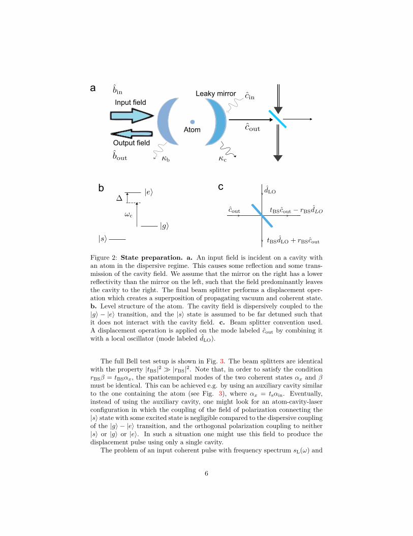
Realistic scenarioWe now show a scheme aiming to produce the state (1) in a cavity QED scenario.The first part of the scheme is depicted in Fig. 2a. An input field is incidenton a cavity with a single three level atom prepared initially in a superpositionof the states g and s: |ψ〉atom = cos ν|s〉 + sin ν|g〉. Fig. 2b shows the levelstructure of the atom. Transition |g〉 − |e〉 is coupled dispersively to the cavitywith detuning ∆ = ωge − ωc, where ωc is the cavity frequency and ωge is thefrequency of the transition |g〉 − |e〉. The cavity is asymmetric with decay ratesof the mirrors κb � κc and the cavity decay rate κ = κb + κc. This means thatthe field leaks out of the cavity essentially only through the right mirror (cf.Fig. 2a). The fact that one needs an asymmetric cavity is not a priori obviousand will be explained below. We assume that the level |s〉 is detuned far enoughsuch that it does not interact with the cavity field.
Since the cavity transmission depends on the atomic state, the atom-cavitysystem acts as a filter that transforms the initial state |αin〉|ψ〉atom in the fol-lowing way:
|αin〉 ⊗ |g〉 −→ |rgαin〉refl ⊗ |g〉 ⊗ |tgαin〉trans (7)|αin〉 ⊗ |s〉 −→ |rsαin〉refl ⊗ |s〉 ⊗ |tsαin〉trans (8)
where |〉refl and |〉trans represent the reflected and transmitted photonic states,αin is the complex amplitude of the input coherent state and rj and tj (j = s, g)are the amplitude reflectivity and transmitivity of the empty cavity (atom in thestate |s〉, i.e. j = s) and of the cavity with the atom (atom in the state |g〉,i.e.j = g) and |rj |2 + |tj |2 = 1. Notice that we assume that both the reflected andtransmitted fields are still coherent states (see Methods for details).
In order to produce a state of the form (1), one needs to meet the followingconditions: ts = 0 with 〈rsαin|rgαin〉 ∼= 1 and |tgαin〉 = |α〉, where |α〉 is thedesired coherent state in (1). An alternative is to apply a displacement on thetransmitted field [24]. The displacement is just the result of combining a fieldexiting the atom-cavity system (cout mode) with a coherent local oscillator |β〉(dLO mode) on a beam splitter, as depicted in Fig. 2c. The output port ofinterest is the port with the output field |tBScout − rBSdLO〉, where rBS and tBSare the amplitude reflectivity and transmitivity of the beam splitter respectively.For a coherent state, |αx〉, in the cout mode, one can achieve a zero amplitudein this output port by tuning the amplitude of |β〉 such that rBSβ = tBSαx. Inour case, αx = tsαin and one can obtain the state |s, 0〉 contained in (1).
5
Atom
Input field
Output field
Leaky mirrora
b c
Figure 2: State preparation. a. An input field is incident on a cavity withan atom in the dispersive regime. This causes some reflection and some trans-mission of the cavity field. We assume that the mirror on the right has a lowerreflectivity than the mirror on the left, such that the field predominantly leavesthe cavity to the right. The final beam splitter performs a displacement oper-ation which creates a superposition of propagating vacuum and coherent state.b. Level structure of the atom. The cavity field is dispersively coupled to the|g〉 − |e〉 transition, and the |s〉 state is assumed to be far detuned such thatit does not interact with the cavity field. c. Beam splitter convention used.A displacement operation is applied on the mode labeled cout by combining itwith a local oscillator (mode labeled dLO).
The full Bell test setup is shown in Fig. 3. The beam splitters are identicalwith the property |tBS|2 � |rBS|2. Note that, in order to satisfy the conditionrBSβ = tBSαx, the spatiotemporal modes of the two coherent states αx and βmust be identical. This can be achieved e.g. by using an auxiliary cavity similarto the one containing the atom (see Fig. 3), where αx = tsαin. Eventually,instead of using the auxiliary cavity, one might look for an atom-cavity-laserconfiguration in which the coupling of the field of polarization connecting the|s〉 state with some excited state is negligible compared to the dispersive couplingof the |g〉 − |e〉 transition, and the orthogonal polarization coupling to neither|s〉 or |g〉 or |e〉. In such a situation one might use this field to produce thedisplacement pulse using only a single cavity.
The problem of an input coherent pulse with frequency spectrum sL(ω) and
6
Homodyne Measurement
Photodetection
Local oscillator
Optical switch
Auxiliary cavity
Atom-cavitysystem
Input field
Loss
Loss
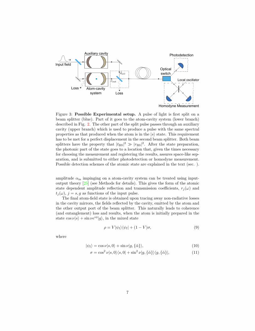
Figure 3: Possible Experimental setup. A pulse of light is first split on abeam splitter (blue). Part of it goes to the atom-cavity system (lower branch)described in Fig. 2. The other part of the split pulse passes through an auxiliarycavity (upper branch) which is used to produce a pulse with the same spectralproperties as that produced when the atom is in the |s〉 state. This requirementhas to be met for a perfect displacement in the second beam splitter. Both beamsplitters have the property that |tBS|2 � |rBS|2. After the state preparation,the photonic part of the state goes to a location that, given the times necessaryfor choosing the measurement and registering the results, assures space-like sep-aration, and is submitted to either photodetection or homodyne measurement.Possible detection schemes of the atomic state are explained in the text (sec. ).
amplitude αin impinging on a atom-cavity system can be treated using input-output theory [25] (see Methods for details). This gives the form of the atomicstate dependent amplitude reflection and transmission coefficients, rj(ω) andtj(ω), j = s, g as functions of the input pulse.
The final atom-field state is obtained upon tracing away non-radiative lossesin the cavity mirrors, the fields reflected by the cavity, emitted by the atom andthe other output port of the beam splitter. This naturally leads to coherence(and entanglement) loss and results, when the atom is initially prepared in thestate cos ν|s〉+ sin νeiφ|g〉, in the mixed state
ρ = V |ψf〉〈ψf |+ (1− V )σ, (9)
where
|ψf〉 = cos ν|s, 0〉+ sin ν|g, {α}〉, (10)σ = cos2 ν|s, 0〉〈s, 0|+ sin2 ν|g, {α}〉〈g, {α}|, (11)
7
and the visibility V is (see Methods for details),
V = exp[− F |α|
2
2t2BS
], (12)
F = r2BS + fcav + IsL
14C (1 + fcav), (13)
IsL =∫dω|sL(ω) 1
D(ω) |2∫
dω|sL(ω) 1D(ω)
11+i2(ω−ωc)/κ |2
, (14)
D(ω) = (Γ2 + i(ω − ωge))(κ/2 + i(ω − ωc)) + g2, (15)
where C is the usual single-atom cooperativity C = g2
Γκ and fcav = κb+κLκc
isa factor which describes the asymmetry of the cavity. Here, the continuousfrequency coherent state, |{α}〉, is
|{α}〉 = exp[tBSαin
∫dω sL(ω) (tg(ω)− ts(ω)) c†out(ω) + h.c.
]|0〉, (16)
|α|2 = |tBSαin|2∫dω∣∣sL(ω)(tg(ω)− ts(ω))
∣∣2, (17)
with the transmission coefficients
ts(ω) =√κbκc
κ/2 + i(ω − ωc) , (18)
tg(ω) =√κbκc
D(ω)
(Γ2 + i(ω − ωge)
), (19)
and the atomic state is initially prepared with φ such that the final state is ofthe form (10). In the above, sL(ω) is the frequency spectrum of the laser field,g is the coupling constant of the cavity mode to the |g〉 − |e〉 transition, Γ isthe transverse decay rate of the |e〉 state and κL is the loss rate of the cavitymirrors.
From equation (12), it is easy to see that for F → 0, we have V → 1.Also for F → 0, we need the 3 conditions, rBS → 0, fcav → 0 and C →∞. In practice, the first condition means that one should use a small value ofthe beam splitter reflectivity and adjust the amplitude of the local oscillator,such that the condition rBSβ = tBStsαin is still satisfied. The second conditionis precisely the requirement of the asymmetric cavity we have mentioned atthe beginning of this section and is dependent only on the transmission andlosses of the cavity mirrors used. For completeness, we have also included non-radiative mirror losses. The third condition means that one needs large single-atom cooperativity. One remarkable feature of this result is that for C � 1,the visibility V (but of course not the state) is independent of the details of thespectrum of the input pulse.
The final point to note is that to satisfy the approximations used in ourderivation, we require a negligible probability of exciting the atom throughout
8
the duration of the input pulse. This is important, since, to maintain somespecific amplitude of the output coherent state |{α}〉 after the beam splitter,one might have to use a very large amplitude input laser if the integral inequation (17) is small. For the sake of this theoretical analysis, we consider thecase of an input Gaussian pulse with the normalized spectrum
|sL(ω)|2 = 1γL√πe−(ω−ωLγL
)2
, (20)
where ωL is the central laser frequency, and γL is the bandwidth of the pulse.To close the locality loophole, one has to propagate the outgoing pulse for
some minimum distance, given by the larger of the measurement times of theatom and the pulse, which depends on the pulse duration. The pulse durationis given by the relevant time scale of the system, i.e., either by the input pulseduration or the cavity lifetime, whichever is greater. This means that, from thepoint of view of closing the locality loophole, it is useful to push the duration ofthe input pulse down to the cavity lifetime, but not necessarily further. Sincethe pulse duration and the cavity lifetime are proportional to the inverse of thepulse bandwidth γL and the cavity decay rate κ respectively, the best case wouldbe if γL ≈ κ.
−2..5
−1.5
2 3 5 10 15 20−3
−2
−1
2.5
2 3 5 10 15 20
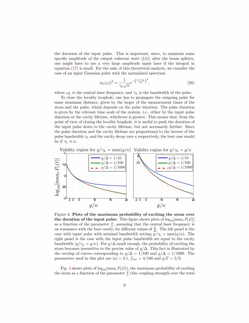
Figure 4: Plots of the maximum probability of exciting the atom overthe duration of the input pulse. This figure shows plots of log10[maxt Pe(t)]as a function of the parameter g
κ , assuming that the central laser frequency ison resonance with the bare cavity, for different values of g
∆ . The left panel is thecase with input pulse with minimal bandwidth setting g/γL = max(g/κ). Theright panel is the case with the input pulse bandwidth set equal to the cavitybandwidth (g/γL = g/κ). For g/∆ small enough, the probability of exciting theatom becomes insensitive to the precise value of g/∆. This fact is illustrated bythe overlap of curves corresponding to g/∆ = 1/100 and g/∆ = 1/1000. Theparameters used in this plot are |α| = 2.1, fcav = 4/100 and g/Γ = 5/3.
Fig. 4 shows plots of log10(maxt Pe(t)), the maximum probability of excitingthe atom as a function of the parameter g
κ (the coupling strength over the total
9
cavity decay rate), assuming that the central laser frequency is on resonancewith the bare cavity, for g
∆ = 1/10, 1/100, 1/1000. The left figure is the casefor a fixed minimal bandwidth of the input pulse in the sense that we chooseγL such that g/γL = max(g/κ). The right figure corresponds to the situationwhen the input pulse bandwidth is set equal to the cavity bandwidth in order tominimize the pulse duration. In the following, we will consider the regions where(maxt Pe(t)) ≤ 0.1, to be the parameter regimes when our analysis is suitable.As is evident from Fig. 4, for some large g/γL, there always exists some g/κ forwhich our solutions are self-consistent, which is not the case when γL = κ, thesituation minimizing the pulse duration. We can thus look for some intermediatevalue of γL (having all the other parameters fixed), which minimizes the pulseduration while still respecting the validity of the used approximation. This isthe strategy we employ in the next section, where we will discuss a possibleimplementation of our scheme using realistic experimental parameters.
Experimental feasibilitySo far, we theoretically described a general cavity scenario. In the following, wewill focus our attention on possible implementations of our scheme in opticalcavities. This implementation has the advantage of allowing large propagationdistances due to the availability of low loss optical fibers.
We start by general constraints on measurement times and propagation dis-tances imposed by the locality loophole. To close the locality loophole, onerequires the start of the measurement event on one side to be space-like sepa-rated from the end of the measurement event on the other side. In other words,we need that the space-time coordinates of the end of the atomic measurementand the choice of measurement basis (photon detection or homodyning) on thephotonic side be space-like separated, and vice versa. This constraint translatesinto the minimum propagation distance
d ≥ c (max ((∆tph,c + ∆tph,m), (∆tat,c + ∆tat,m))) , (21)
where c is the speed of light in free-space, ∆tat/ph,c is the time required on theatomic/photonic side to choose the measurement settings, which also includesthe time to change the measurement basis, ∆tat/ph,m is the time required onthe atomic/photonic side to perform the actual measurement, which necessarilyincludes the duration of the light pulse. We assume that the main time con-straint is set by the atomic measurement, which is typically slower than themeasurement of photons. The above equation shows, that even if we used avery short pulse, we would still need to propagate it at least to a distance, givenby the sum of atomic measurement time and the time required to choose a basis(a rotation in the space of |s〉 and |g〉, typically using RF pulses), multipliedby c. The best trade-off in this case, is thus to have ∆tph,m ≈ ∆tat,m + ∆tat,c.This is possible because the time needed to choose a basis on the photonic sidecan be very fast [7].
One possibility to perform a fast atomic state detection would be to usea 2-photon ionization technique [20]. This technique has been performed in
10
free-space configurations and can achieve 98% efficiency in < 1 µs. Althoughthe restriction of a small cavity might make such a photo-ionization techniquetechnically challenging, proposals to make focusing cavities with large physicalvolumes (lengths of ∼ 1 cm) while still maintaining large coupling constants(g ∼ 100MHz) exist [26, 27] potentially making such techniques compatible.Here, we assume ∆tat,m +∆tat,c = 1 µs. We should thus seek to produce a pulsewhich requires a total measurement duration up to 1 µs. For the Gaussian pulseexample considered in our calculation, we take the total pulse measurementduration to be ∆tph,m = 6
√2/γL,m. The factor 6
√2 is chosen such that if
the bandwidth of the pulse incident on the cavity is γL,m, then the neglectedtails of the outgoing pulse correspond to <0.5% of the total integrated intensityof the outgoing pulse (for the parameters used in Table 2, see below). For ameasurement time of 1 µs, this corresponds to γL,m = 2π × 1.35MHz. It alsomeans that for outgoing pulse bandwidths γL > γL,m (shorter pulses), the totalmeasurement time is set by ∆tat,m+∆tat,c = 1 µs and the minimum propagationdistance is 300 m.
Next, we use experimental parameters given in [28, 29, 30]. These exper-iments use 852 nm and 780 nm light respectively, which are subject to about2 dB/km loss in optical fibers. In the following, we compare both experimentsand possible modifications. As discussed previously, we will work in the largedetuning regime, ∆� g. We choose an arbitrary, but subjected to experimentalconstraints, value of g/∆ = 1/10. This ensures that we respect all approxima-tions used, as long as we also satisfy condition maxt Pe(t) ≤ 0.1. The figure ofmerit in both cases will be γ0.1, which is the largest acceptable laser bandwidththat satisfies condition maxt Pe(t) ≈ 0.1, and the state production visibility(12), which is computed using the actual laser bandwidth ≡ min(κ, γ0.1, γL,m).We also include the effect of finite pulse measurement time on the visibility,using (12)-(15). We assume |α| = 2.1 and |rBS|2 = 0.001. Table 2 summarizesthe results.
The parameters of Ref. [28, 29] are (g/(2π), κ/(2π),Γ/(2π), fcav) = (34 MHz,4.1MHz, 2.6MHz, 10/4) (we assume that the experiment performed implementsa symmetric cavity). Due to the symmetry of the cavity, one obtains a smalleffective visibility. Assuming that the cavity could be made asymmetric reducingfcav to the current value in the experiment of Ref. [30], the visibility dramaticallyincreases to 72.7% (second row). Neglecting the mirror losses, we show in thethird row that V can be as high as 90.8%.
The parameters of Ref. [30] are (g/(2π), κ/(2π),Γ/(2π), fcav) = (5MHz,3MHz, 3MHz, 14/100). As the setup stands, the visibility is 56.3%. However,neglecting the mirror losses, V increases to 71.3% (fifth row). If it were furtherpossible to reduce the total cavity decay rate by a factor of 2, thus increasingthe cooperativity, while maintaining the same asymmetry, the visibility furtherincreases to 77.2% (sixth row). The required incident photon number can becalculated from (17). For the parameters in Table 2 and requiring the resultingphoton number, |α|2 = 2.12, one requires |αin|2 ≈ 25− 400 input photons.
For the specific case of 87Rb, one might also identify possible states playingthe role of |g〉, |s〉 and |e〉. We may choose for example the |s〉 state to be the
11
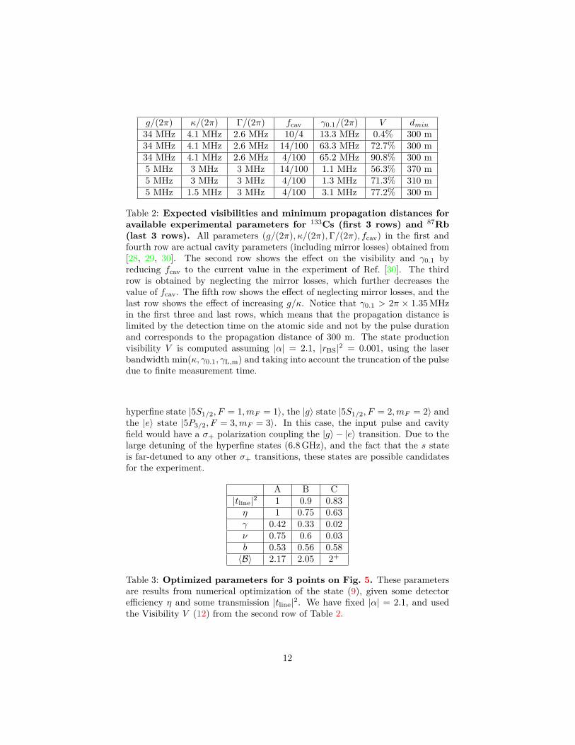
g/(2π) κ/(2π) Γ/(2π) fcav γ0.1/(2π) V dmin34 MHz 4.1 MHz 2.6 MHz 10/4 13.3 MHz 0.4% 300 m34 MHz 4.1 MHz 2.6 MHz 14/100 63.3 MHz 72.7% 300 m34 MHz 4.1 MHz 2.6 MHz 4/100 65.2 MHz 90.8% 300 m5 MHz 3 MHz 3 MHz 14/100 1.1 MHz 56.3% 370 m5 MHz 3 MHz 3 MHz 4/100 1.3 MHz 71.3% 310 m5 MHz 1.5 MHz 3 MHz 4/100 3.1 MHz 77.2% 300 m
Table 2: Expected visibilities and minimum propagation distances foravailable experimental parameters for 133Cs (first 3 rows) and 87Rb(last 3 rows). All parameters (g/(2π), κ/(2π),Γ/(2π), fcav) in the first andfourth row are actual cavity parameters (including mirror losses) obtained from[28, 29, 30]. The second row shows the effect on the visibility and γ0.1 byreducing fcav to the current value in the experiment of Ref. [30]. The thirdrow is obtained by neglecting the mirror losses, which further decreases thevalue of fcav. The fifth row shows the effect of neglecting mirror losses, and thelast row shows the effect of increasing g/κ. Notice that γ0.1 > 2π × 1.35MHzin the first three and last rows, which means that the propagation distance islimited by the detection time on the atomic side and not by the pulse durationand corresponds to the propagation distance of 300 m. The state productionvisibility V is computed assuming |α| = 2.1, |rBS|2 = 0.001, using the laserbandwidth min(κ, γ0.1, γL,m) and taking into account the truncation of the pulsedue to finite measurement time.
hyperfine state |5S1/2, F = 1,mF = 1〉, the |g〉 state |5S1/2, F = 2,mF = 2〉 andthe |e〉 state |5P3/2, F = 3,mF = 3〉. In this case, the input pulse and cavityfield would have a σ+ polarization coupling the |g〉 − |e〉 transition. Due to thelarge detuning of the hyperfine states (6.8GHz), and the fact that the s stateis far-detuned to any other σ+ transitions, these states are possible candidatesfor the experiment.
A B C|tline|2 1 0.9 0.83η 1 0.75 0.63γ 0.42 0.33 0.02ν 0.75 0.6 0.03b 0.53 0.56 0.58〈B〉 2.17 2.05 2+
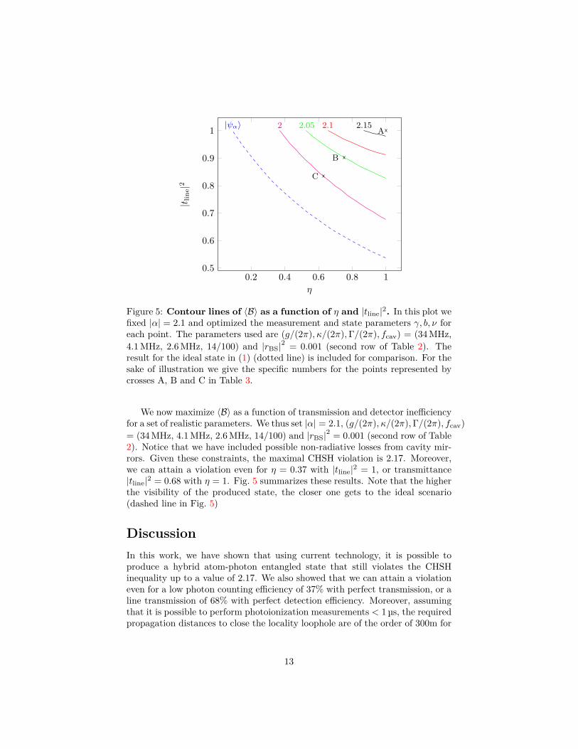
Table 3: Optimized parameters for 3 points on Fig. 5. These parametersare results from numerical optimization of the state (9), given some detectorefficiency η and some transmission |tline|2. We have fixed |α| = 2.1, and usedthe Visibility V (12) from the second row of Table 2.
12
0.2 0.4 0.6 0.8 10.5
0.6
0.7
0.8
0.9
1 2 2.05 2.1 2.15|ψα〉A
B
C
η
|t lin
e|2
Figure 5: Contour lines of 〈B〉 as a function of η and |tline|2. In this plot wefixed |α| = 2.1 and optimized the measurement and state parameters γ, b, ν foreach point. The parameters used are (g/(2π), κ/(2π),Γ/(2π), fcav) = (34MHz,4.1MHz, 2.6MHz, 14/100) and |rBS|2 = 0.001 (second row of Table 2). Theresult for the ideal state in (1) (dotted line) is included for comparison. For thesake of illustration we give the specific numbers for the points represented bycrosses A, B and C in Table 3.
We now maximize 〈B〉 as a function of transmission and detector inefficiencyfor a set of realistic parameters. We thus set |α| = 2.1, (g/(2π), κ/(2π),Γ/(2π), fcav)= (34MHz, 4.1MHz, 2.6MHz, 14/100) and |rBS|2 = 0.001 (second row of Table2). Notice that we have included possible non-radiative losses from cavity mir-rors. Given these constraints, the maximal CHSH violation is 2.17. Moreover,we can attain a violation even for η = 0.37 with |tline|2 = 1, or transmittance|tline|2 = 0.68 with η = 1. Fig. 5 summarizes these results. Note that the higherthe visibility of the produced state, the closer one gets to the ideal scenario(dashed line in Fig. 5)
DiscussionIn this work, we have shown that using current technology, it is possible toproduce a hybrid atom-photon entangled state that still violates the CHSHinequality up to a value of 2.17. We also showed that we can attain a violationeven for a low photon counting efficiency of 37% with perfect transmission, or aline transmission of 68% with perfect detection efficiency. Moreover, assumingthat it is possible to perform photoionization measurements < 1 µs, the requiredpropagation distances to close the locality loophole are of the order of 300m for
13
optical setups. This gives a very good outlook for optical systems in eventuallyperforming a loophole-free Bell test.
In principle, one may also consider circuit QED setups. The advantages ofsuch setups are twofold. First, the very fast and efficient qubit state detection,on the order of 10ns [12] potentially lowers the required propagation distancesto laboratory scale distances (10m or less). Second, in this system, large ratiosof coupling constant to cavity decay, g/κ, can be achieved. The drawbacks withcurrent technology are the limited efficiencies of both photodetection and homo-dyne detection (private communication with Steve Girvin), and the requirementto cool the propagation line down to cryogenic temperatures. The hope is thatboth these drawbacks, being of technological nature, can be eventually overcomein near future experiments.
Before finishing let us compare our present results with previous proposalsinvolving similar setups. In Ref. [16] a Bell test involving the production of anentangled state between an atom and a photonic field created by atomic decaywas studied (see also [31]). It was shown that Bell violations with photodetectionefficiency of 39% (see green curve in Fig. 1) can be achieved. Note however thatthis number refers to the ideal state, considering that all light emitted by theatom is collected. Our scheme overcomes this problem since the photonic partof the state is the transmitted mode, and, moreover, requires lower efficiencies.
We believe that our proposal will trigger possible implementations of loophole-free Bell tests with atom-photon interfaces, which are particularly important inquantum communication and cryptographic applications.
MethodsInput-output relationsHere we derive the input-output relations [25] for a two-sided cavity, clearlystating the approximations used, and their validity. We consider a cavity mode(a mode) which couples to a left mode (b mode) and a right mode (c mode).We also include loss in the mirrors of the cavity as the coupling of the cavity amode to an additional L mode.These give the following Heisenberg equation of motion for the cavity field,
∂ta(t) = − i~
[Hsys , a(t)]− κ
2a(t)
+√κbbin(t) +√κccin(t) +√κLLin(t), (22)
where κ = κb + κc + κL and Hsys is the system Hamiltonian (empty cavity orcavity with atom) without considering the baths, which is either
Hempty = ~ωca†a or, (23)
Hatom−cavity = ~ωca†a+ ~ωaσ
†σ + ~g(a†σ + aσ†). (24)
14
Equation (22) can also be written in the equivalent way
∂ta(t) = − i~
[Hsys , a(t)]− kc
2 a(t)
+√κbbin(t)−√κccout(t) +√κLLin(t), (25)
where kα = κ − 2κα and we now consider the output operator for the c mode,where the input and output operators are defined as,
Oin(t) = −1√2π
∫dω Oω(t0)e−iω(t−t0), (26)
Oout(t) = 1√2π
∫dω Oω(t1)e−iω(t−t1). (27)
For the case of an empty cavity, these equations are just a linear system ofdifferential equations, and can be solved simply by Fourier transforms definedas
f(t) = 1√2π
∫dω e−iωtf(ω), (28)
f(ω) = 1√2π
∫dt eiωtf(t), (29)
to give bin(ω)cin(ω)Lin(ω)
= Us
bout(ω)cout(ω)Lout(ω)
, (30)
where
Us =
rb(ω) tb(ω) lb(ω)tb(ω) rc(ω) lc(ω)lb(ω) lc(ω) rL(ω)
(31)
rα(ω) = −( kα2 + i(ω − ωc)κ2 + i(ω − ωc)
)(32)
tb(ω) =√κbκc
κ2 + i(ω − ωc) (33)
lb/c(ω) =√κLκb/c
κ2 + i(ω − ωc) (34)
These are relations used in the main text when the atom is in the |s〉 state,since it is assumed to be decoupled from all cavity and environmental modes.However, when the atom is in the |g〉 state, it is assumed to couple to the cavitya mode. In this situation, one has to include atomic spontaneous emission. Thiscan be done by including the coupling of the |g〉−|e〉 transition to an additional
15
bath, E mode, different from the cavity. This gives the set of equations
∂ta(t) = − i~
[Hatom−cavity , a(t)]− κ
2a(t)
+√κbbin(t) +√κccin(t) +√κLLin(t), (35)
∂tσ(t) = − i~
[Hatom−cavity , σ(t)]− Γ2 σ(t)−
√ΓσzEin(t), (36)
where Γ describes the rate of emission into modes other than the cavity modes,and σin is the input operator of the environment. Note that Γ can be madesmall if the physical cavity mode has a large spatial overlap with the emissionpattern of the |g〉 − |e〉 transition.
In the following, we will investigate the system dynamics in the low excitationregime. The reason is twofold. First, we want to avoid exciting the atom inorder to prevent the decay into the environment (spontaneous emission withthe decay rate Γ). Second, populating the excited state would induce a morecomplex dynamics producing in general a nontrivial entangled state betweenthe atom and input, output and cavity fields. This is certainly an interestingregime to investigate in the context of quantum state engineering, but in thepresent paper we focus on the more intuitive picture in the spirit of (8). Theassumption of the atom occupying mostly the ground state can be translatedas σz ≈ −11. With this assumption, the above set of equations can be solvedanalytically. Proceeding analogously to the empty cavity case, we have
bin(ω)cin(ω)Lin(ω)Ein(ω)
= Ug
bout(ω)cout(ω)Lout(ω)Eout(ω)
, (37)
where the unitary matrix
Ug = 1D(ω)
Us(Γ2 + iδa)(κ2 + iδc) ig
√Γ~ν
ig√
Γ~νT (Γ2 − iδa)(κ2 + iδc)
− g211
, (38)
with δa = ω−ωge, δc = ω−ωc, Us is defined in equation (31), the vector ~ν reads
~ν =
√κb√κc√κL
(39)
andD(ω) = (Γ
2 + iδa)(κ2 + iδc) + g2. (40)
Notice that this set of equations reduces to (30) for the b and c modes, wheng = 0. Finally, we also assume that all output operators (bout, cout, Lout, Eout)commute with each other, which is not true in general. This approximation isrequired, for an input coherent field in the bin mode to transform into a coherent
16
reflected field in the bout mode and coherent fields in the cout, Lout and Eoutmodes.
Lastly, as a consistency check of our work, we note that the approxima-tion σz ≈ −11 necessarily requires that the atom remains in the ground statethroughout its evolution. Solving for σ(ω), one obtains
σ(ω) ≈ −ig√κbbin(ω)(Γ
2 − iδa)(κ2 − iδc) + g2 , (41)
where we have used the fact that the cin and σin modes represent thermal noiseand are thus taken to be negligible compared to the bin mode. Taking the inversefourier transform, one obtains
Pe(t) =⟨σ†σ(t)
⟩= 1
2π
∣∣∣∣∣∫
dω ig√κbsL(ω)
(Γ2 − i(ω − ωa))(κ2 − i(ω − ωc)) + g2 e
−iωt
∣∣∣∣∣2
.
(42)We then conclude that the self-consistency of our approximation requires that⟨σ†σ(t)
⟩� 1, ∀t, which implies that maxt Pe(t)� 1. Notice that this condition
is a necessary but not sufficient condition for the approximation σz ≈ −11, sincethis condition itself is derived under the approximation. However, it should benoted that equation (41) can be written in terms of a(ω) to obtain
σ(ω) ≈ −igΓ2 − i(ω − ωa)
a(ω). (43)
= −igi∆(1− ω−ωc
∆ + Γ2i∆ )
a(ω) (44)
Then, for ∆� ω − ωc,Γ, meaning that if the laser addresses only wavelengthsclose to the bare cavity resonance compared to the detuning between the atomand the cavity, and the atom-cavity detuning is many atomic linewidths awayfrom resonance, one has the condition⟨
σ†σ(t)⟩≈( g
∆
)2 ⟨a†a(t)
⟩� 1, (45)
which is the condition of validity of the dispersive approximation (see [32]). Thismeans that the condition ∆� ω−ωc,Γ, together with condition maxt Pe(t)�1, is sufficient to justify the approximation σz ≈ −11.
Derivation of visibilityThe state produced after the cavity and beam splitter is of the form
cos ν|s, 0〉 ⊗ |αo, αb, αL, αE〉+ sin ν|g, α〉 ⊗ |αo′, αb
′, αL′, αE
′〉 (46)
where o,b,L and E are the other port of the beam splitter, the reflected fieldfrom the cavity, the field loss in cavity mirrors and the spontaneous emission
17
term respectively. If we measure only the atomic state and the a mode, we loseinformation in all the other modes. Tracing over all the rest of the modes, weobtain the state (9), where the visibility, V is,
V = |〈αo|αo′〉〈αb|αb
′〉〈αL|αL′〉〈αE|αE
′〉| (47)
We take only the magnitude of the inner products, since the total phase can, inprinciple, be compensated by suitable atomic state preparation. This gives theexpression
V = exp[− F |α|
2
2t2BS
], (48)
F = fcav + IsL
14C (1 + fcav) + r2
BS, (49)
IsL =∫dω|sL(ω) 1
D(ω) |2∫
dω|sL(ω) 1D(ω)
11+i2(ω−ωc)/κ |2
, (50)
C = g2
Γκ, (51)
fcav = κb + κL
κc, (52)
where, as in the main text, tBS and rBS are the transmittivity and reflectivityof the beam splitter used in the displacement operation, sL(ω) is the spectrumof the laser input field and κi is the coupling rate of the cavity mode to the ithbath.
References[1] A. Acín, N. Brunner, N. Gisin, S. Massar, S. Pironio, and V. Scarani,
“Device-Independent Security of Quantum Cryptography against CollectiveAttacks,” Phys. Rev. Lett. 98, 230501 (2007).
[2] S. Pironio, A. Acín, S. Massar, A. B. d. l. Giroday, D. N. Matsukevich,P. Maunz, S. Olmschenk, D. Hayes, L. Luo, T. A. Manning, and C. Monroe,“Random numbers certified by Bell’s theorem,” Nature 464, 1021–1024(2010).
[3] C.-E. Bardyn, T. C. H. Liew, S. Massar, M. McKague, and V. Scarani,“Device-independent state estimation based on Bell’s inequalities,” Phys.Rev. A 80, 062327 (2009).
[4] R. Rabelo, M. Ho, D. Cavalcanti, N. Brunner, and V. Scarani, “Device-Independent Certification of Entangled Measurements,” Phys. Rev. Lett.107, 050502 (2011).
[5] N. Brunner, D. Cavalcanti, S. Pironio, V. Scarani, S. Wehner. “Bell nonlo-cality”, Preprint at http://arxiv.org/abs/1303.2849 (2013).
18
[6] A. Aspect, J. Dalibard, and G. Roger, “Experimental Test of Bell’s In-equalities Using Time- Varying Analyzers,” Phys. Rev. Lett. 49, 1804–1807(1982).
[7] G. Weihs, T. Jennewein, C. Simon, H. Weinfurter, and A. Zeilinger, “Vio-lation of Bell’s Inequality under Strict Einstein Locality Conditions,” Phys.Rev. Lett. 81, 5039–5043 (1998).
[8] T. Scheidl, R. Ursin, J. Kofler, S. Ramelow, X. Ma, T. Herbst,L. Ratschbacher, A. Fedrizzi, N. K. Langford, T. Jennewein, andA. Zeilinger, “Violation of Local Realism with Freedom of Choice,” PNAS107, 19708–19713 (2010).
[9] M. Giustina, A. Mech, S. Ramelow, B. Wittmann, J. Kofler, J. Beyer,A. Lita, B. Calkins, T. Gerrits, S. W. Nam, R. Ursin, A. Zeilinger, “Bellviolation using entangled photons without the fair-sampling assumption,”Nature (2013).
[10] D. N. Matsukevich, P. Maunz, D. L. Moehring, S. Olmschenk, and C. Mon-roe, “Bell Inequality Violation with Two Remote Atomic Qubits,” Phys.Rev. Lett. 100, 150404 (2008).
[11] M. A. Rowe, D. Kielpinski, V. Meyer, C. A. Sackett, W. M. Itano, C. Mon-roe, and D. J. Wineland, “Experimental violation of a Bell’s inequality withefficient detection,” Nature 409, 791–794 (2001).
[12] M. Ansmann, H. Wang, R. C. Bialczak, M. Hofheinz, E. Lucero, M. Neeley,A. D. O’Connell, D. Sank, M. Weides, J. Wenner, A. N. Cleland, and J. M.Martinis, “Violation of Bell’s inequality in Josephson phase qubits,” Nature461, 504–506 (2009).
[13] D. Cavalcanti, N. Brunner, P. Skrzypczyk, A. Salles, and V. Scarani, “Largeviolation of Bell inequalities using both particle and wave measurements,”Phys. Rev. A 84, 022105 (2011).
[14] M. Túlio Quintino, M. Araújo, D. Cavalcanti, M. França Santos, andM. Terra Cunha, “Maximal violations and efficiency requirements for Belltests with photodetection and homodyne measurements,” J. Phys. A:Math. Theor. 45, 215308 (2012).
[15] M. Araújo, M. Túlio Quintino, D. Cavalcanti, M. França Santos, A. Ca-bello, and M. Terra Cunha, “Bell tests with arbitrarily low photodetec-tion efficiency and homodyne measurements,” Phys. Rev. A 86, 030101(R)(2012).
[16] N. Sangouard, J.-D. Bancal, N. Gisin, W. Rosenfeld, P. Sekatski, M. Weber,and H. Weinfurter, “Loophole-free Bell test with one atom and less thanone photon on average,” Phys. Rev. A 84, 052122 (2011).
19
[17] J. F. Clauser, M. A. Horne, A. Shimony, and R. A. Holt, “Proposed Ex-periment to Test Local Hidden-Variable Theories,” Phys. Rev. Lett. 23,880–884 (1969).
[18] N. Brunner, N. Gisin, V. Scarani, and C. Simon, “Detection Loophole inAsymmetric Bell Experiments,” Phys. Rev. Lett. 98, 220403 (2007).
[19] A. Cabello and J.-Å. Larsson, “Minimum Detection Efficiency for aLoophole-Free Atom-Photon Bell Experiment,” Phys. Rev. Lett. 98, 220402(2007).
[20] F. Henkel, M. Krug, J. Hofmann, W. Rosenfeld, M. Weber, and H. We-infurter, “Highly Efficient State-Selective Submicrosecond PhotoionizationDetection of Single Atoms,” Phys. Rev. Lett. 105, 253001 (2010).
[21] J. B. Brask, N. Brunner, D. Cavalcanti, and J. Leverrier, “The use of am-plifiers in continuous-variable Bell tests,” Phys. Rev. A 85, 042116 (2012).
[22] P. H. Eberhard, “Background level and counter efficiencies required fora loophole-free Einstein-Podolsky-Rosen experiment,” Phys. Rev. A 47,R747–R750 (1993).
[23] J.-Å. Larsson and J. Semitecolos, “Strict detector-efficiency bounds for n-site Clauser-Horne inequalities,” Phys. Rev. A 63, 022117 (2001).
[24] M. G. A. Paris, “Displacement operator by beam splitter,” Phys. Lett. A217, 78–80 (1996).
[25] D. Walls and G. J. Milburn, Quantum Optics. Springer, 2nd ed., Feb.,2008.
[26] S. A. Aljunid, B. Chng, M. Paesold, G. Maslennikov and C. Kurtsiefer,“Interaction of light with a single atom in the strong focusing regime”,Preprint at http://arxiv.org/abs/1006.2191 (2010).
[27] S. E. Morrin, C. C. Yu and T. W. Mossberg, “Strong Atom-Cavity Couplingover Large Volumes and the Observation of Subnatural Intracacvity AtomicLinewidths”, Phys. Rev. Lett., 73, 1489 (1994)
[28] K. Birnbaum, A. Boca, R. Miller, A. Boozer, T. Northup, and H. Kimble,“Photon blockade in an optical cavity with one trapped atom,” Nature 436,87–90 (2005).
[29] C. J. Hood, “Real-time Measurement and Trapping of Single Atoms bySingle Photons” PhD dissertation, California Institute of Technology (2000)
[30] S. Ritter, C. Nölleke, C. Hahn, A. Reiserer, A. Neuzner, M. Uphoff,M. Mücke, E. Figueroa, J. Bochmann, and G. Rempe, “An elementaryquantum network of single atoms in optical cavities,” Nature 484, 195–200(2012).
20
[31] J. B. Brask and R. Chaves, “Robust nonlocality tests with displacement-based measurements”, Phys. Rev. A 86, 010103(R) (2012).
[32] M. Boissonneault, J. M. Gambetta, and A. Blais, “Dispersive regime of cir-cuit QED: Photon-dependent qubit dephasing and relaxation rates,” Phys.Rev. A 79, 013819 (2009).
AcknowledgementsWe would like to thank Ignacio Cirac for pointing out the issue of cooperativityand also Gerhard Rempe, Stephan Ritter, Serge Haroche, Christian Kurtsiefer,Gleb Maslennikov, Matthias U. Staudt, Antonio Badolato, Dario Gerace andSteve Girvin for useful discussions. This work was supported by the Brazilianagencies Fapemig, Capes, CNPq, and INCT-IQ, the National Research Foun-dation and the Ministry of Education of Singapore.
Authors contributionsM. Araújo, M. T. Quintino, D. Cavalcanti, M. T. Cunha, and M. F. Santosworked on the ideal case and Bell test proposal. C. Teo, J. Minář, M. F. Santos,and V. Scarani, developed the calculations for the realistic case. All authorsdiscussed the results and wrote the manuscript.
Competing financial interestsThe authors declare no competing financial interests.
21
Related Documents


![Quantum optical experiments towards atom-photon entanglement · But all distributed quantum computation and scalable quantum communication protocols [17] require to coherently transfer](https://static.cupdf.com/doc/110x72/5f3af9d98a7a6c3d94604dca/quantum-optical-experiments-towards-atom-photon-entanglement-but-all-distributed.jpg)


