Real Time Operating Systems Terminology Reference McDermott EE382N-4 uC/OS-III, The Real-Time Kernel, or a High Performance, Scalable, ROMable, Preemptive, Multitasking Kernel for Microprocessors, Microcontrollers & DSPs , Book & Board Included, Hardcover, by Jean J Labrosse, $199.95 MicroC OS II: The Real Time Kernel , by Jean J. Labrosse , 2002, ISBN 1-5782-0103-9, $72.76 The Definitive Guide to the ARM Cortex-M3 TI , Second Edition, Paperback, Joseph Yiu, $53.95 Chapters 5 8 13, Embedded Microcomputer Systems: Real Time Interfacing, Third Edition, Jonathan W. Valvano, ISBN 1111426252, $83

Welcome message from author
This document is posted to help you gain knowledge. Please leave a comment to let me know what you think about it! Share it to your friends and learn new things together.
Transcript
Real Time Operating Systems
Terminology
Reference McDermott EE382N-4
uC/OS-III, The Real-Time Kernel, or a High Performance, Scalable, ROMable, Preemptive, Multitasking Kernel for Microprocessors, Microcontrollers & DSPs, Book & Board Included, Hardcover, by Jean J Labrosse, $199.95 MicroC OS II: The Real Time Kernel, by Jean J. Labrosse , 2002, ISBN 1-5782-0103-9, $72.76
The Definitive Guide to the ARM Cortex-M3 TI, Second Edition, Paperback, Joseph Yiu, $53.95
Chapters 5 8 13, Embedded Microcomputer Systems: Real Time Interfacing, Third Edition, Jonathan W. Valvano, ISBN 1111426252, $83
Thread or Task
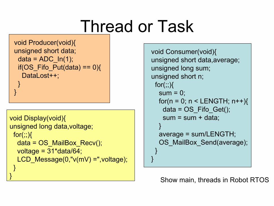
void Display(void){ unsigned long data,voltage; for(;;){ data = OS_MailBox_Recv(); voltage = 31*data/64; LCD_Message(0,"v(mV) =",voltage); } }
void Producer(void){ unsigned short data; data = ADC_In(1); if(OS_Fifo_Put(data) == 0){ DataLost++; } }
void Consumer(void){ unsigned short data,average;unsigned long sum;unsigned short n; for(;;){ sum = 0; for(n = 0; n < LENGTH; n++){ data = OS_Fifo_Get(); sum = sum + data; } average = sum/LENGTH; OS_MailBox_Send(average); }}
Show main, threads in Robot RTOS
Real-time tasks
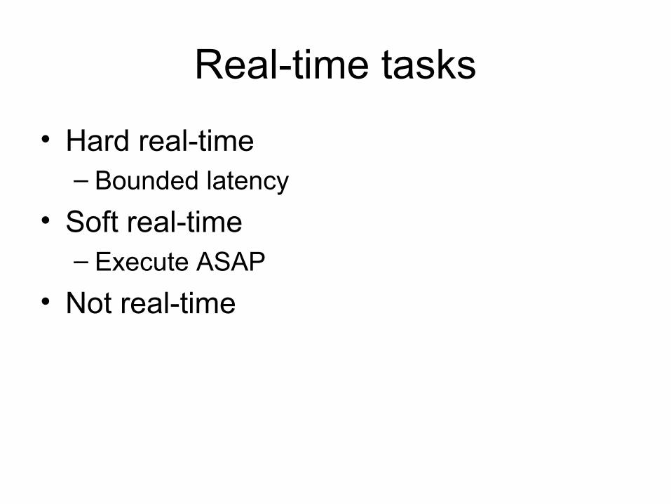
• Hard real-time– Bounded latency
• Soft real-time– Execute ASAP
• Not real-time

Thread Classification
• Periodic, execution at regular intervals– E.g., ADC, DAC, motor control– E.g., Check CO levels
• Aperiodic, execution can not be anticipated– Execution is frequent– E.g., New position detected as wheel turns
• Sporadic, execution can not be anticipated– Execution is infrequent– E.g., Faults, errors, catastrophes
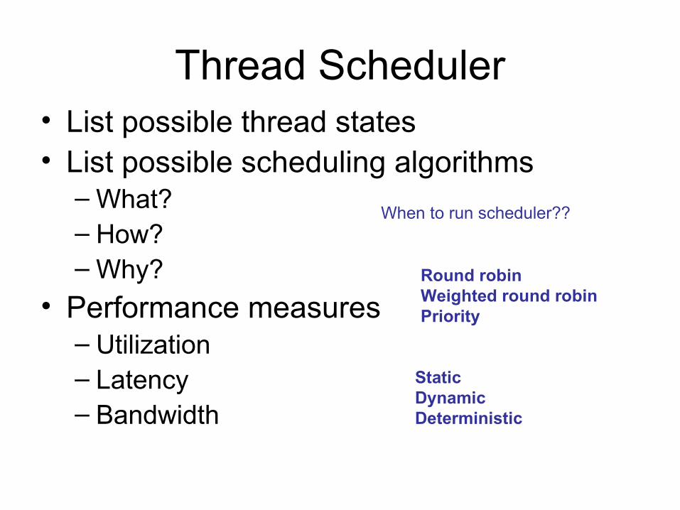
Thread Scheduler• List possible thread states• List possible scheduling algorithms
– What?– How?– Why?
• Performance measures– Utilization– Latency– Bandwidth
Round robinWeighted round robinPriority
StaticDynamicDeterministic
When to run scheduler??
Priority
• Execute highest priority first– Can you have two tasks at same priority?
• Minimize latency on real-time tasks
• Assign a dollar cost for delays– Minimize cost
Priority Schedulers
• Earliest deadline first, dynamic
• Earliest slack-time first , dynamic– Slack = (time to deadline)-(work left to do)
• Rate monotonic scheduling, static– Assign priority based on how often Ti is runs– Lower Ti (more frequent) are higher priority
Rate Monotonic Scheduling Theorem
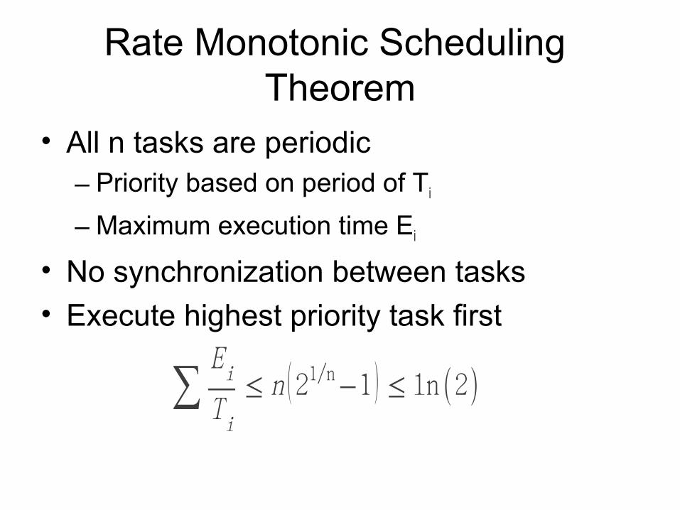
• All n tasks are periodic – Priority based on period of Ti
– Maximum execution time Ei
• No synchronization between tasks
• Execute highest priority task first
∑Ei
Ti
≤ n (21/n−1 ) ≤ ln (2)
Time Management
• System time
• Time stamps– When did it occur?– Performance measures
• Thread sleeping
• Measurements– Input capture period -> wheel RPM– Input capture PW -> ultrasonic distance
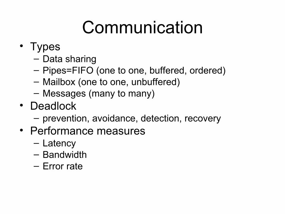
Communication• Types
– Data sharing– Pipes=FIFO (one to one, buffered, ordered)– Mailbox (one to one, unbuffered)– Messages (many to many)
• Deadlock – prevention, avoidance, detection, recovery
• Performance measures– Latency– Bandwidth– Error rate
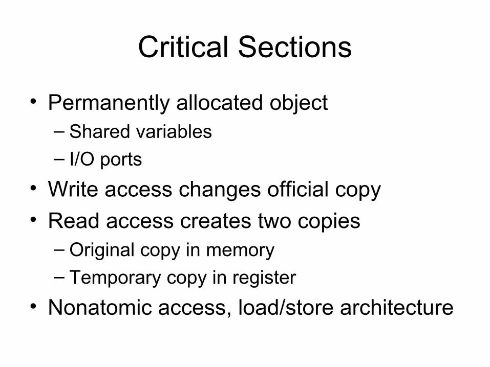
Critical Sections
• Permanently allocated object– Shared variables
– I/O ports
• Write access changes official copy
• Read access creates two copies– Original copy in memory– Temporary copy in register
• Nonatomic access, load/store architecture
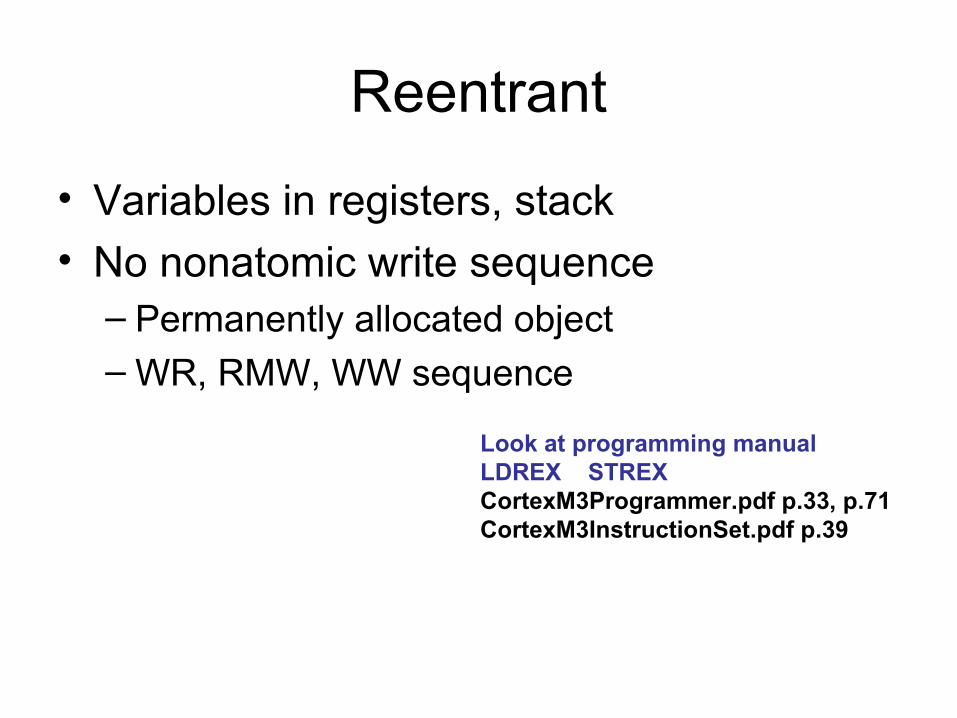
Reentrant
• Variables in registers, stack
• No nonatomic write sequence– Permanently allocated object– WR, RMW, WW sequence
Look at programming manualLDREX STREXCortexM3Programmer.pdf p.33, p.71CortexM3InstructionSet.pdf p.39
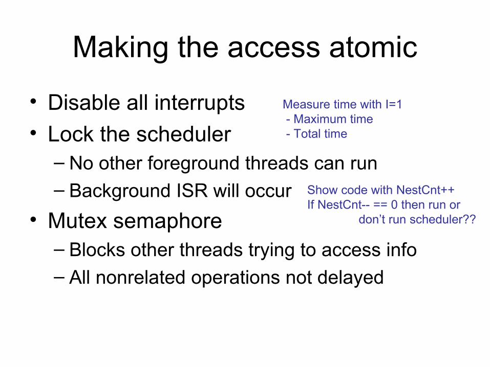
Making the access atomic
• Disable all interrupts
• Lock the scheduler – No other foreground threads can run– Background ISR will occur
• Mutex semaphore– Blocks other threads trying to access info– All nonrelated operations not delayed
Show code with NestCnt++If NestCnt-- == 0 then run or don’t run scheduler??
Measure time with I=1 - Maximum time - Total time
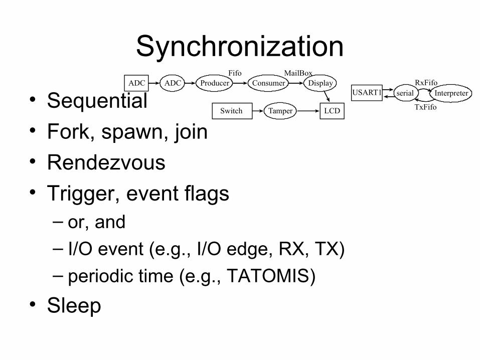
Synchronization
• Sequential
• Fork, spawn, join
• Rendezvous
• Trigger, event flags– or, and– I/O event (e.g., I/O edge, RX, TX) – periodic time (e.g., TATOMIS)
• Sleep
ADC ADC Producer ConsumerFifo
DisplayMailBox
LCDSwitch Tamper
InterpreterRxFifo
USART1 serial
TxFifo
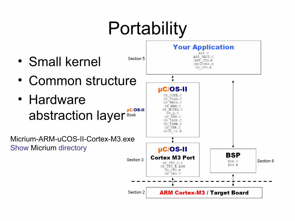
Portability
• Small kernel
• Common structure
• Hardware abstraction layer
Micrium-ARM-uCOS-II-Cortex-M3.exeShow Micrium directory
Hooks
• Run user supplied code at strategic places
• Allows you to– Extend the OS– Implement debugging– Implement performance testing
– Implement black box recording
• Collect run-time performance data
Additional OS terms
• Run-time configurable – Priority, stack size, fifo size, time slice
• Certification– Medical, transportation, nuclear, military
• Scalable– 10 threads versus 200 threads
• ROMable
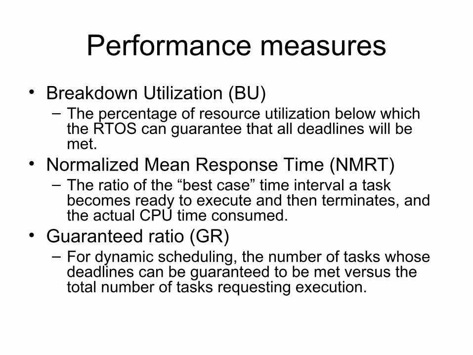
Performance measures
• Breakdown Utilization (BU)– The percentage of resource utilization below which
the RTOS can guarantee that all deadlines will be met.
• Normalized Mean Response Time (NMRT)– The ratio of the “best case” time interval a task
becomes ready to execute and then terminates, and the actual CPU time consumed.
• Guaranteed ratio (GR)– For dynamic scheduling, the number of tasks whose
deadlines can be guaranteed to be met versus the total number of tasks requesting execution.
Case Study: Tone Generationhttp://www.toneconnect.com/
• Components– the software modules that are required to
generate the tones as a function of switch inputs
• Operational Organization– the structure of the interactions between the
software modules
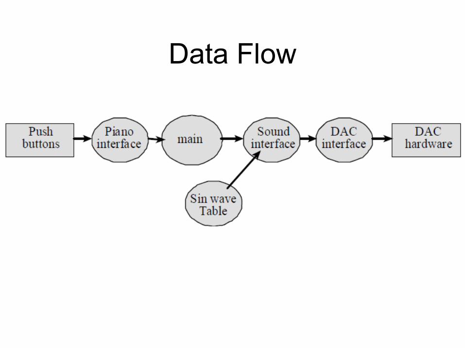
Data Flow
21
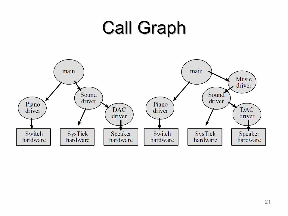
Call GraphCall Graph
SysTick Periodic Interrupts
• SysTick Timer– source of interrupts with fixed period– useful for data acquisition and control
systems• ADC and DAC applications
– alternative to busy/wait polling• periodic polling• free foreground from continuous polling• useful for low bandwidth devices
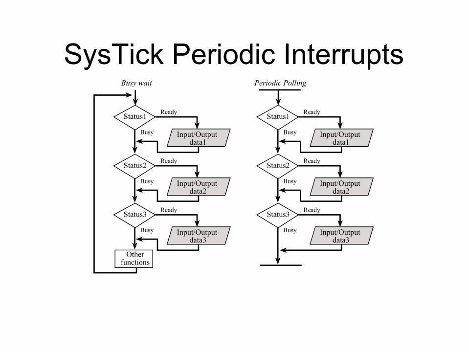
SysTick Periodic Interrupts
Status1
Input/Output data1
Busy
Ready
Status2
Input/Output data2
Busy
Ready
Status3
Input/Output data3
Busy
Ready
Otherfunctions
Busy wait
Status1
Input/Output data1
Busy
Ready
Status2
Input/Output data2
Busy
Ready
Status3
Input/Output data3
Busy
Ready
Periodic Polling
SysTick Periodic Interrupts
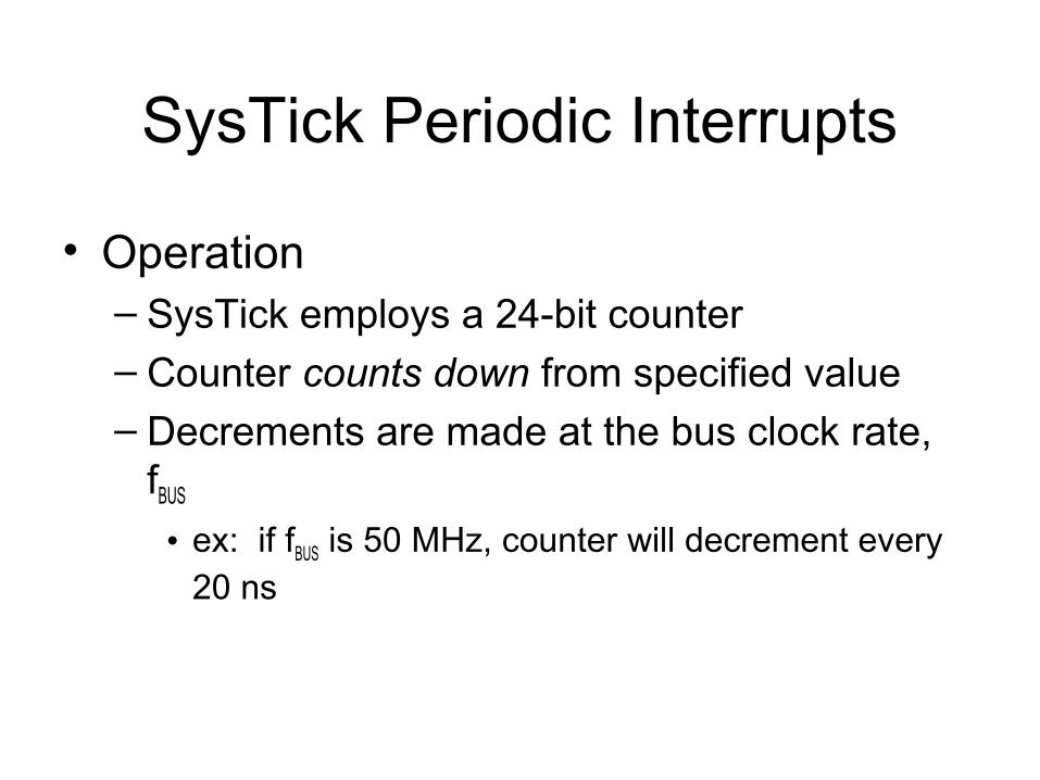
• Operation– SysTick employs a 24-bit counter– Counter counts down from specified value– Decrements are made at the bus clock rate,
fBUS
• ex: if fBUS is 50 MHz, counter will decrement every 20 ns
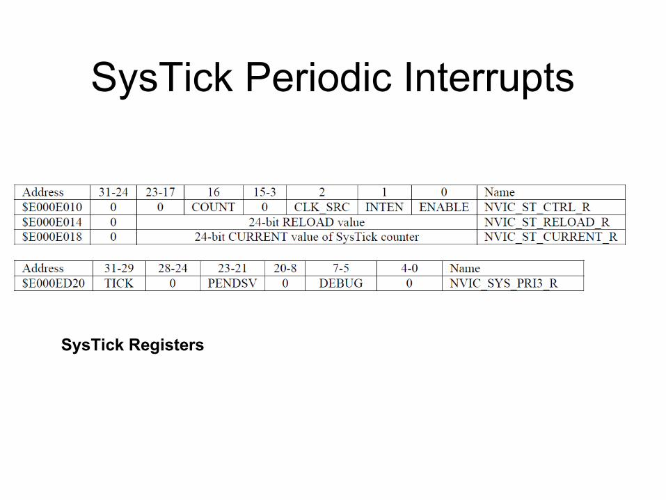
SysTick Periodic Interrupts
SysTick Registers
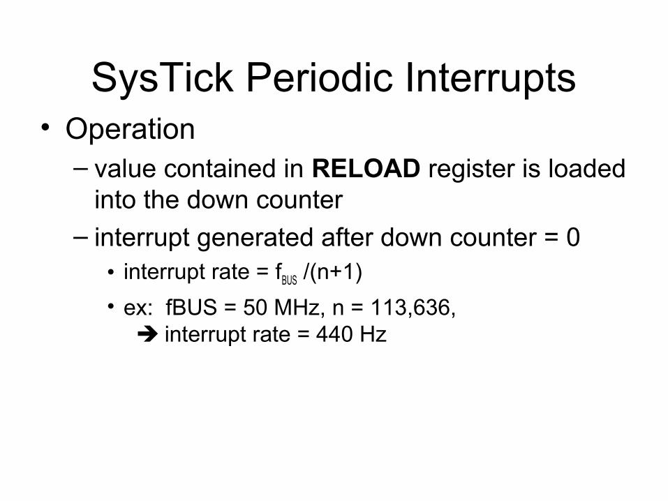
SysTick Periodic Interrupts• Operation
– value contained in RELOAD register is loaded into the down counter
– interrupt generated after down counter = 0• interrupt rate = fBUS /(n+1)
• ex: fBUS = 50 MHz, n = 113,636, interrupt rate = 440 Hz
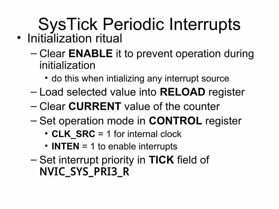
SysTick Periodic Interrupts• Initialization ritual
– Clear ENABLE it to prevent operation during initialization
• do this when intializing any interrupt source
– Load selected value into RELOAD register– Clear CURRENT value of the counter– Set operation mode in CONTROL register
• CLK_SRC = 1 for internal clock• INTEN = 1 to enable interrupts
– Set interrupt priority in TICK field of NVIC_SYS_PRI3_R
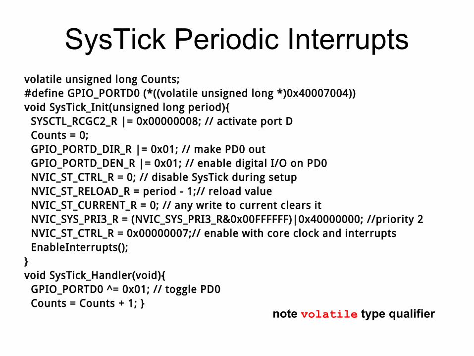
SysTick Periodic Interruptsvolatile unsigned long Counts;#define GPIO_PORTD0 (*((volatile unsigned long *)0x40007004))void SysTick_Init(unsigned long period){ SYSCTL_RCGC2_R |= 0x00000008; // activate port D Counts = 0; GPIO_PORTD_DIR_R |= 0x01; // make PD0 out GPIO_PORTD_DEN_R |= 0x01; // enable digital I/O on PD0 NVIC_ST_CTRL_R = 0; // disable SysTick during setup NVIC_ST_RELOAD_R = period - 1;// reload value NVIC_ST_CURRENT_R = 0; // any write to current clears it NVIC_SYS_PRI3_R = (NVIC_SYS_PRI3_R&0x00FFFFFF)|0x40000000; //priority 2 NVIC_ST_CTRL_R = 0x00000007;// enable with core clock and interrupts EnableInterrupts();}void SysTick_Handler(void){ GPIO_PORTD0 ^= 0x01; // toggle PD0 Counts = Counts + 1; }
note volatile type qualifier
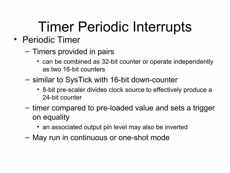
Timer Periodic Interrupts• Periodic Timer
– Timers provided in pairs• can be combined as 32-bit counter or operate independently
as two 16-bit counters
– similar to SysTick with 16-bit down-counter• 8-bit pre-scaler divides clock source to effectively produce a
24-bit counter
– timer compared to pre-loaded value and sets a trigger on equality
• an associated output pin level may also be inverted
– May run in continuous or one-shot mode
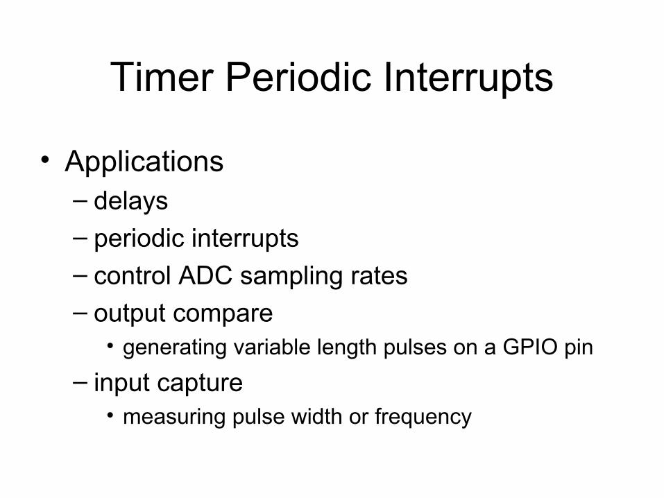
Timer Periodic Interrupts
• Applications– delays– periodic interrupts– control ADC sampling rates– output compare
• generating variable length pulses on a GPIO pin
– input capture• measuring pulse width or frequency
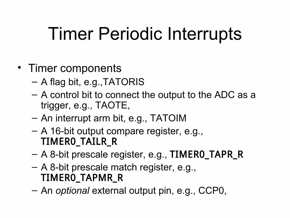
Timer Periodic Interrupts
• Timer components– A flag bit, e.g.,TATORIS– A control bit to connect the output to the ADC as a
trigger, e.g., TAOTE,– An interrupt arm bit, e.g., TATOIM– A 16-bit output compare register, e.g.,
TIMER0_TAILR_R– A 8-bit prescale register, e.g., TIMER0_TAPR_R– A 8-bit prescale match register, e.g.,
TIMER0_TAPMR_R– An optional external output pin, e.g., CCP0,
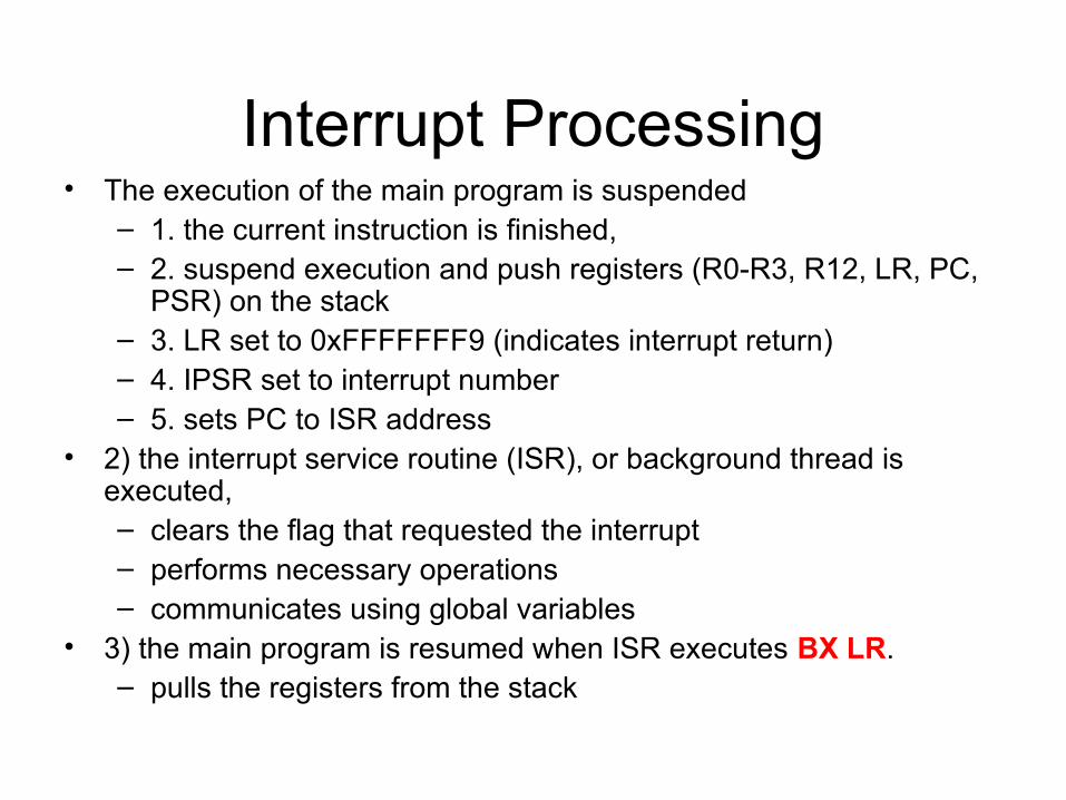
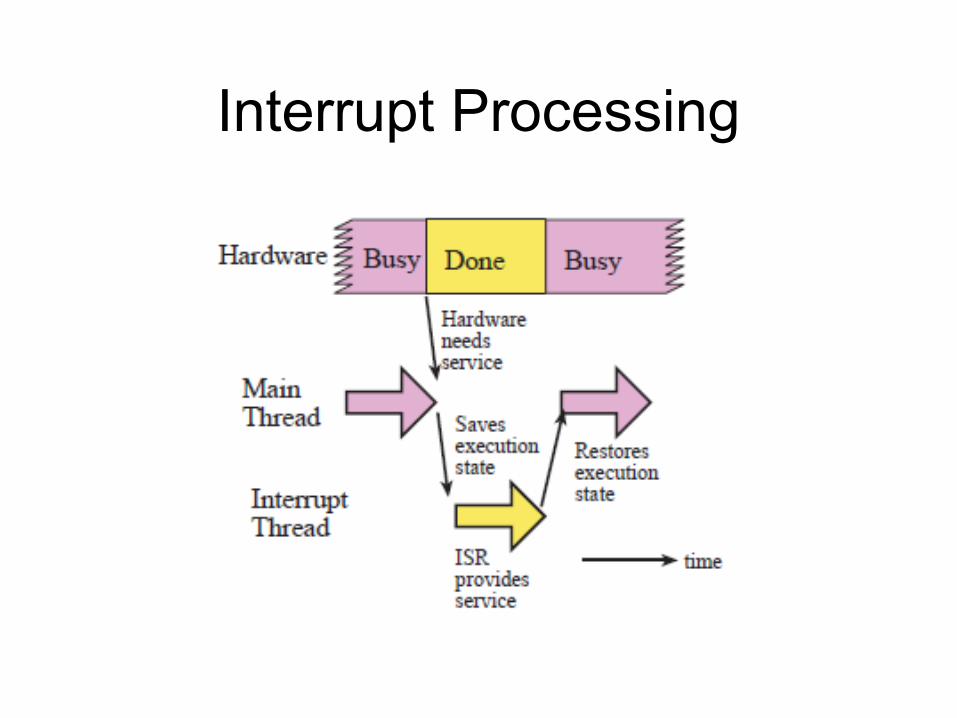
Interrupt Processing• The execution of the main program is suspended
– 1. the current instruction is finished,– 2. suspend execution and push registers (R0-R3, R12, LR, PC,
PSR) on the stack– 3. LR set to 0xFFFFFFF9 (indicates interrupt return)– 4. IPSR set to interrupt number– 5. sets PC to ISR address
• 2) the interrupt service routine (ISR), or background thread is executed,– clears the flag that requested the interrupt– performs necessary operations– communicates using global variables
• 3) the main program is resumed when ISR executes BX LR.– pulls the registers from the stack
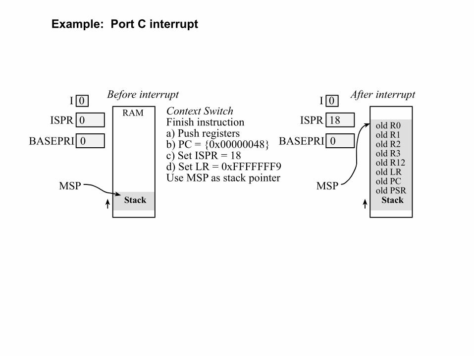
old R0old R1old R2old R3old R12old LRold PCold PSR
Context SwitchFinish instructiona) Push registersb) PC = {0x00000048}c) Set ISPR = 18d) Set LR = 0xFFFFFFF9Use MSP as stack pointer
Before interrupt
RAM
Stack
I 0
ISPR 0
MSP
BASEPRI 0
After interrupt
Stack
I 0
ISPR 18
MSP
BASEPRI 0
Example: Port C interrupt
Interrupt Processing
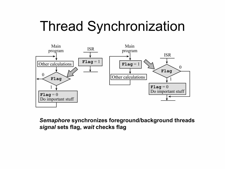
Thread Synchronization
Other calculations
1
0
Mainprogram ISR
Flag = 0Do important stuff
Flag
Flag = 1
Other calculations 1
0
Mainprogram
ISR
Flag = 0Do important stuff
Flag
Flag = 1
Semaphore synchronizes foreground/background threadssignal sets flag, wait checks flag
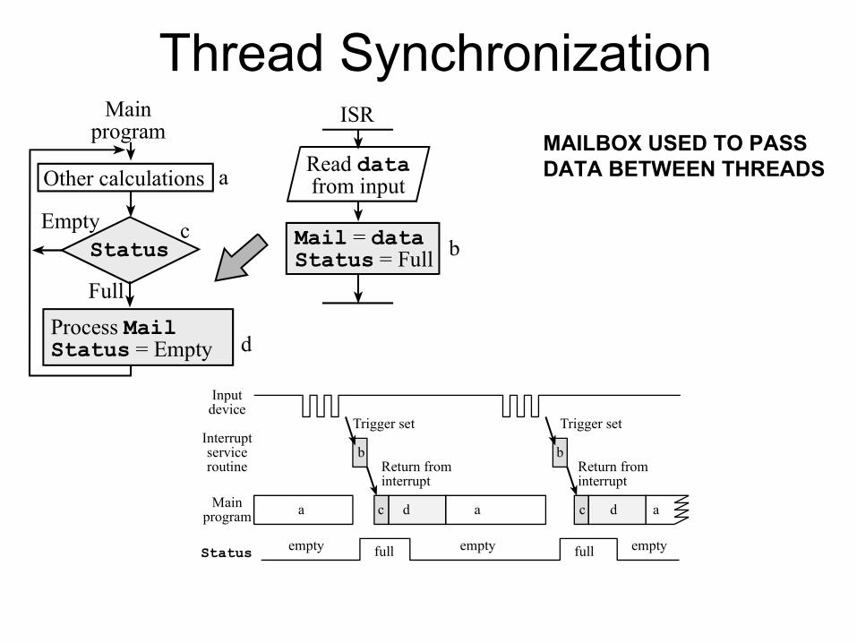
Thread Synchronization
Other calculationsRead datafrom input
Full
Empty
Mainprogram
ISR
Process MailStatus = Empty
Status Mail = dataStatus = Full
a
bc
d
Inputdevice
Mainprogram
Interruptserviceroutine
a
Trigger set
b
c d a
b
c d a
Status empty full fullempty empty
Trigger set
Return frominterrupt
Return frominterrupt
MAILBOX USED TO PASSDATA BETWEEN THREADS
Interrupt Rituals
• Things you must do in every ritual– Arm (specify a flag may interrupt)– Configure NVIC– Enable Interrupts
Interrupt Service Routine (ISR)
• Things you must do in every interrupt service routine– Acknowledge (clear flag that requested the
interrupt)– Maintain contents of LR
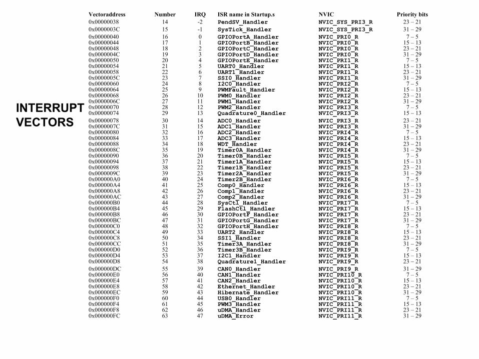
Vectoraddress Number IRQ ISR name in Startup.s NVIC Priority bits0x00000038 14 -2 PendSV_Handler NVIC_SYS_PRI3_R 23 – 210x0000003C 15 -1 SysTick_Handler NVIC_SYS_PRI3_R 31 – 290x00000040 16 0 GPIOPortA_Handler NVIC_PRI0_R 7 – 50x00000044 17 1 GPIOPortB_Handler NVIC_PRI0_R 15 – 130x00000048 18 2 GPIOPortC_Handler NVIC_PRI0_R 23 – 210x0000004C 19 3 GPIOPortD_Handler NVIC_PRI0_R 31 – 290x00000050 20 4 GPIOPortE_Handler NVIC_PRI1_R 7 – 50x00000054 21 5 UART0_Handler NVIC_PRI1_R 15 – 130x00000058 22 6 UART1_Handler NVIC_PRI1_R 23 – 210x0000005C 23 7 SSI0_Handler NVIC_PRI1_R 31 – 290x00000060 24 8 I2C0_Handler NVIC_PRI2_R 7 – 50x00000064 25 9 PWMFault_Handler NVIC_PRI2_R 15 – 130x00000068 26 10 PWM0_Handler NVIC_PRI2_R 23 – 210x0000006C 27 11 PWM1_Handler NVIC_PRI2_R 31 – 290x00000070 28 12 PWM2_Handler NVIC_PRI3_R 7 – 50x00000074 29 13 Quadrature0_Handler NVIC_PRI3_R 15 – 130x00000078 30 14 ADC0_Handler NVIC_PRI3_R 23 – 210x0000007C 31 15 ADC1_Handler NVIC_PRI3_R 31 – 290x00000080 32 16 ADC2_Handler NVIC_PRI4_R 7 – 50x00000084 33 17 ADC3_Handler NVIC_PRI4_R 15 – 130x00000088 34 18 WDT_Handler NVIC_PRI4_R 23 – 210x0000008C 35 19 Timer0A_Handler NVIC_PRI4_R 31 – 290x00000090 36 20 Timer0B_Handler NVIC_PRI5_R 7 – 50x00000094 37 21 Timer1A_Handler NVIC_PRI5_R 15 – 130x00000098 38 22 Timer1B_Handler NVIC_PRI5_R 23 – 210x0000009C 39 23 Timer2A_Handler NVIC_PRI5_R 31 – 290x000000A0 40 24 Timer2B_Handler NVIC_PRI6_R 7 – 50x000000A4 41 25 Comp0_Handler NVIC_PRI6_R 15 – 130x000000A8 42 26 Comp1_Handler NVIC_PRI6_R 23 – 210x000000AC 43 27 Comp2_Handler NVIC_PRI6_R 31 – 290x000000B0 44 28 SysCtl_Handler NVIC_PRI7_R 7 – 50x000000B4 45 29 FlashCtl_Handler NVIC_PRI7_R 15 – 130x000000B8 46 30 GPIOPortF_Handler NVIC_PRI7_R 23 – 210x000000BC 47 31 GPIOPortG_Handler NVIC_PRI7_R 31 – 290x000000C0 48 32 GPIOPortH_Handler NVIC_PRI8_R 7 – 50x000000C4 49 33 UART2_Handler NVIC_PRI8_R 15 – 130x000000C8 50 34 SSI1_Handler NVIC_PRI8_R 23 – 210x000000CC 51 35 Timer3A_Handler NVIC_PRI8_R 31 – 290x000000D0 52 36 Timer3B_Handler NVIC_PRI9_R 7 – 50x000000D4 53 37 I2C1_Handler NVIC_PRI9_R 15 – 130x000000D8 54 38 Quadrature1_Handler NVIC_PRI9_R 23 – 210x000000DC 55 39 CAN0_Handler NVIC_PRI9_R 31 – 290x000000E0 56 40 CAN1_Handler NVIC_PRI10_R 7 – 50x000000E4 57 41 CAN2_Handler NVIC_PRI10_R 15 – 130x000000E8 58 42 Ethernet_Handler NVIC_PRI10_R 23 – 210x000000EC 59 43 Hibernate_Handler NVIC_PRI10_R 31 – 290x000000F0 60 44 USB0_Handler NVIC_PRI11_R 7 – 50x000000F4 61 45 PWM3_Handler NVIC_PRI11_R 15 – 130x000000F8 62 46 uDMA_Handler NVIC_PRI11_R 23 – 210x000000FC 63 47 uDMA_Error NVIC_PRI11_R 31 – 29
INTERRUPTVECTORS
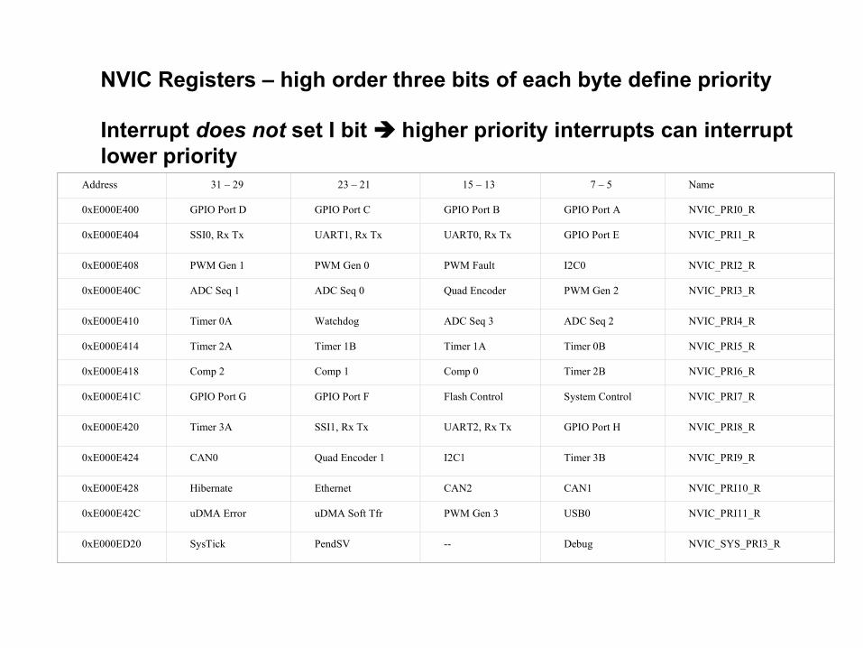
Address 31 – 29 23 – 21 15 – 13 7 – 5 Name
0xE000E400 GPIO Port D GPIO Port C GPIO Port B GPIO Port A NVIC_PRI0_R
0xE000E404 SSI0, Rx Tx UART1, Rx Tx UART0, Rx Tx GPIO Port E NVIC_PRI1_R
0xE000E408 PWM Gen 1 PWM Gen 0 PWM Fault I2C0 NVIC_PRI2_R
0xE000E40C ADC Seq 1 ADC Seq 0 Quad Encoder PWM Gen 2 NVIC_PRI3_R
0xE000E410 Timer 0A Watchdog ADC Seq 3 ADC Seq 2 NVIC_PRI4_R
0xE000E414 Timer 2A Timer 1B Timer 1A Timer 0B NVIC_PRI5_R
0xE000E418 Comp 2 Comp 1 Comp 0 Timer 2B NVIC_PRI6_R
0xE000E41C GPIO Port G GPIO Port F Flash Control System Control NVIC_PRI7_R
0xE000E420 Timer 3A SSI1, Rx Tx UART2, Rx Tx GPIO Port H NVIC_PRI8_R
0xE000E424 CAN0 Quad Encoder 1 I2C1 Timer 3B NVIC_PRI9_R
0xE000E428 Hibernate Ethernet CAN2 CAN1 NVIC_PRI10_R
0xE000E42C uDMA Error uDMA Soft Tfr PWM Gen 3 USB0 NVIC_PRI11_R
0xE000ED20 SysTick PendSV -- Debug NVIC_SYS_PRI3_R
NVIC Registers – high order three bits of each byte define priority
Interrupt does not set I bit higher priority interrupts can interruptlower priority
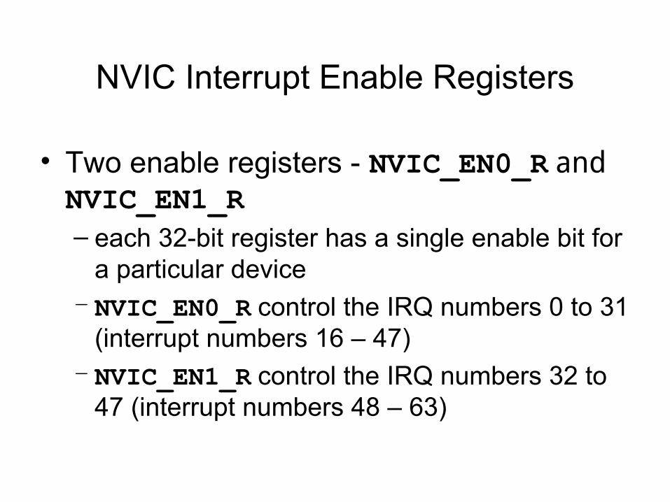
NVIC Interrupt Enable Registers
• Two enable registers - NVIC_EN0_R and NVIC_EN1_R – each 32-bit register has a single enable bit for
a particular device– NVIC_EN0_R control the IRQ numbers 0 to 31
(interrupt numbers 16 – 47)– NVIC_EN1_R control the IRQ numbers 32 to
47 (interrupt numbers 48 – 63)
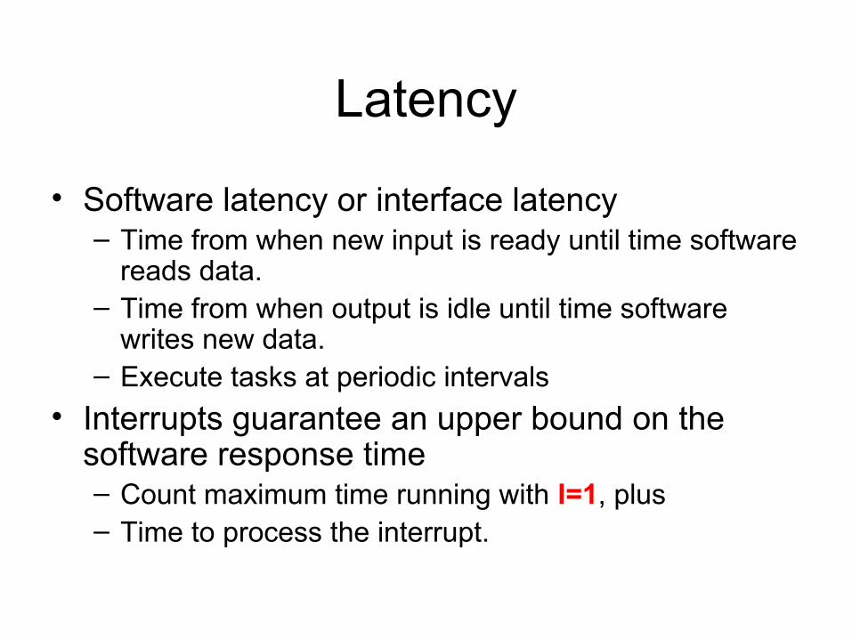
Latency
• Software latency or interface latency– Time from when new input is ready until time software
reads data.– Time from when output is idle until time software
writes new data.– Execute tasks at periodic intervals
• Interrupts guarantee an upper bound on the software response time– Count maximum time running with I=1, plus– Time to process the interrupt.
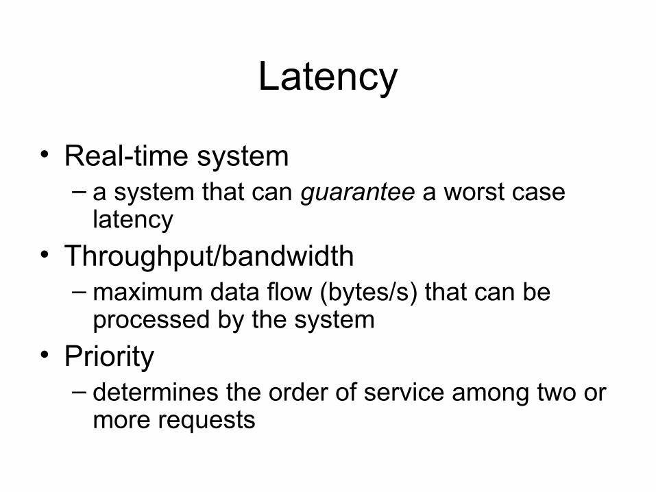
Latency
• Real-time system– a system that can guarantee a worst case
latency
• Throughput/bandwidth– maximum data flow (bytes/s) that can be
processed by the system
• Priority– determines the order of service among two or
more requests

Interrupt Events
• Respond to infrequent but important events.– Alarm conditions like low battery power and– Error conditions can be handled with interrupts.
• Periodic interrupts, generated by the timer at a regular rate– Clocks and timers– Computer-based data input/output– DAC used play music– ADC used to acquire data– Digital control systems.
• I/O synchronization
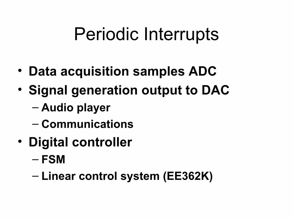
Periodic Interrupts
• Data acquisition samples ADC
• Signal generation output to DAC– Audio player– Communications
• Digital controller– FSM– Linear control system (EE362K)
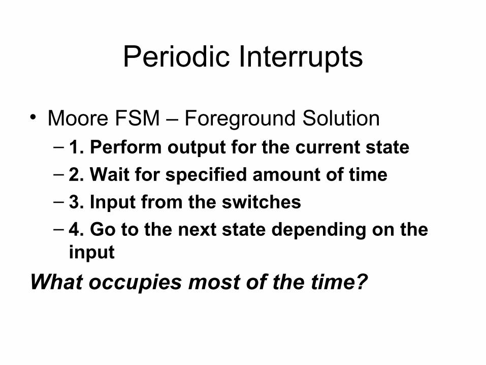
Periodic Interrupts
• Moore FSM – Foreground Solution– 1. Perform output for the current state– 2. Wait for specified amount of time– 3. Input from the switches– 4. Go to the next state depending on the
input
What occupies most of the time?
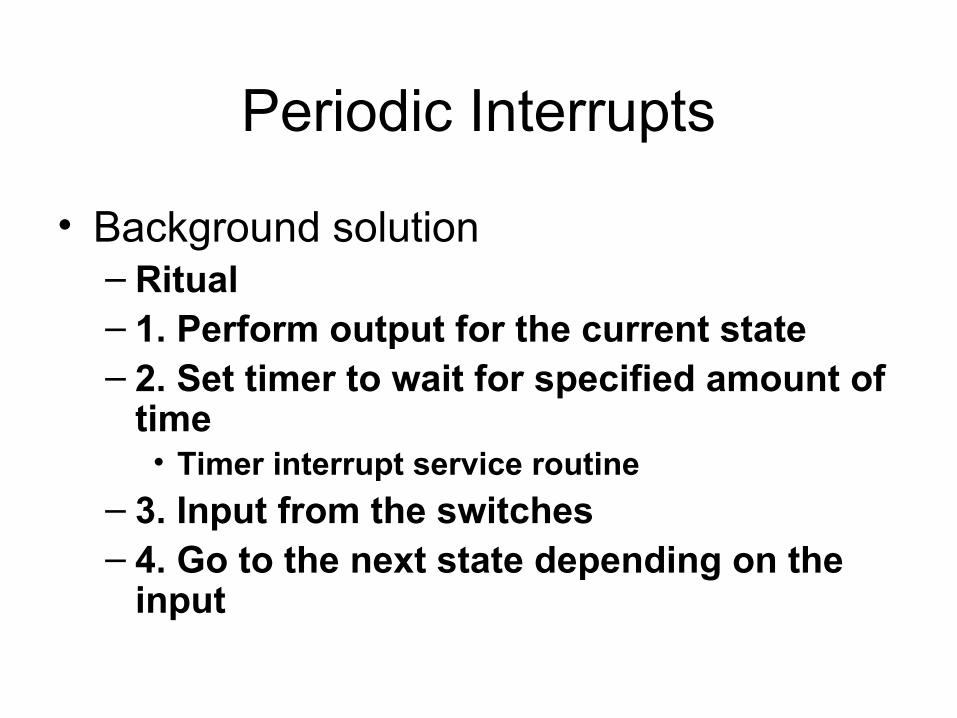
Periodic Interrupts
• Background solution– Ritual– 1. Perform output for the current state– 2. Set timer to wait for specified amount of
time• Timer interrupt service routine
– 3. Input from the switches– 4. Go to the next state depending on the
input
Periodic Interrupts
• Background solution advantages– More accurate– Frees up cycles to perform other tasks
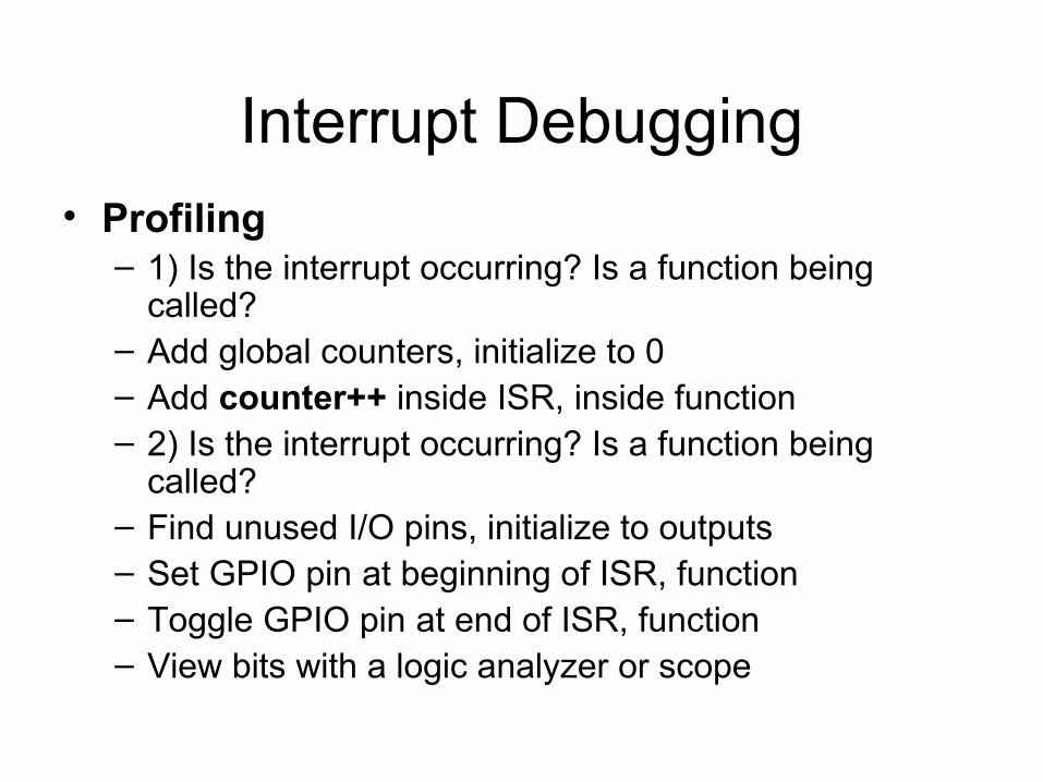
Interrupt Debugging• Profiling
– 1) Is the interrupt occurring? Is a function being called?
– Add global counters, initialize to 0– Add counter++ inside ISR, inside function– 2) Is the interrupt occurring? Is a function being
called?– Find unused I/O pins, initialize to outputs– Set GPIO pin at beginning of ISR, function– Toggle GPIO pin at end of ISR, function– View bits with a logic analyzer or scope
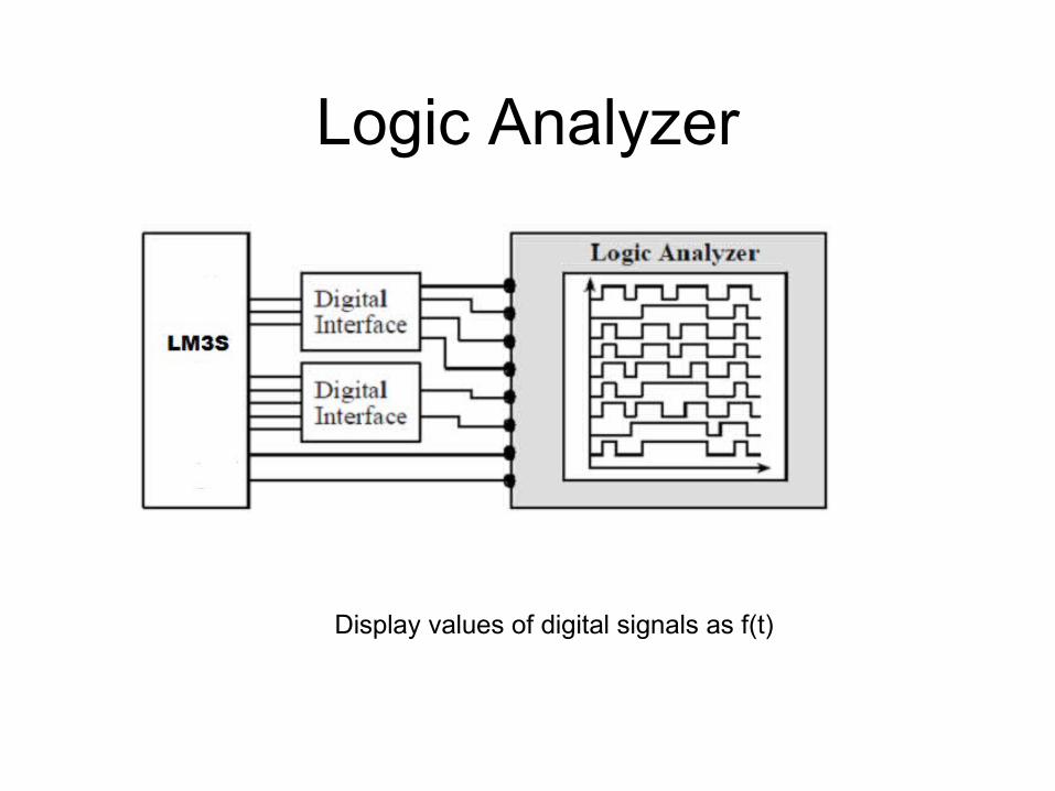
Logic Analyzer
Display values of digital signals as f(t)
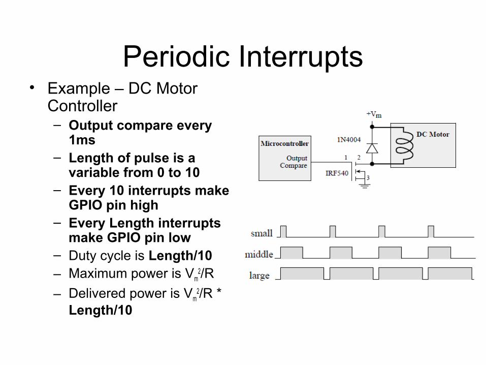
Periodic Interrupts• Example – DC Motor
Controller– Output compare every
1ms– Length of pulse is a
variable from 0 to 10– Every 10 interrupts make
GPIO pin high– Every Length interrupts
make GPIO pin low– Duty cycle is Length/10– Maximum power is Vm
2/R
– Delivered power is Vm2/R *
Length/10
Related Documents


