RNI: DELENG/2005/15153 No: DL(E)-01/5079/17-19 Publication: 15 th of every month Licensed to post without pre-payment U(E) 28/2017-19 Posting: 19 th /20 th of every month at NDPSO Rs.150 Volume XV, Issue 2, February 2019 THE MONTHLY MAGAZINE ON POSITIONING, NAVIGATION AND BEYOND ISSN 0973-2136 Real time kinematic relative positioning accuracy in Brazil GNSS • Navigation • GI data

Welcome message from author
This document is posted to help you gain knowledge. Please leave a comment to let me know what you think about it! Share it to your friends and learn new things together.
Transcript
RNI: DELENG/2005/15153 No: DL(E)-01/5079/17-19 Publication: 15th of every month Licensed to post without pre-payment U(E) 28/2017-19Posting: 19th/20th of every month at NDPSO Rs.150
Volume XV, Issue 2, February 2019 THE MONTHLY MAGAZINE ON POSITIONING, NAVIGATION AND BEYOND
ISSN
0973-2
136
Real time kinematic relative
positioning accuracy in Brazil
GNSS • Navigation • GI data

GNSS Receivers
GNSS Handhelds
Total Stations
Data Collectors
Large Display Tablets
Software SolutionsCHANGE REFLECTS EVOLVING BUSINESSThe new Spectra Geospatial brand builds upon the reputation and equity built under the previous Spectra Precision identity and now reflects the organization’s evolution of providing a broad range of solutions specifically focused on the geospatial industry.
Learn more at www.spectrageospatial.com
©2018 Trimble Inc. All rights reserved. Spectra Geospatial is a Division of Trimble Inc. Spectra Geospatial and the Spectra Geospatial logo are trademarks of Trimble Inc.
Get more than a camera.When you partner with Vexcel Imaging you get more
than a sensor. You get an UltraCam.
You get cutting-edge technology combined with a
progressive service concept for constant product
upgrades, world-class support and one-stop
solutions.
Today and tomorrow.
UltraCam powering
ArticlesAssessment of GNSS real time kinematic relative positioning accuracy based on NTRIP data transmitted by the Brazilian CORS Network (RBMC-IP) S A V ChAChá And L P S ForteS 8 aerial sensor technology: Major advances in efficiency and quality ALexAnder WieChert 21 indian government announces drone policy 2.0 22 Maritime Augmented Reality odd SVeinung hAreide And thomAS PorAthe 31 Why do people participate in standardization of Geographic Information? JonAS LundSten And JeSPer m PAASCh 37
This issue has been made possible by the support and good wishes of the following individuals and companies Alexander Wiechert, Jesper M Paasch, Jonas Lundsten, Odd Sveinung Hareide, L P S Fortes, S A V Chachá and Thomas Porathe and; Carlson, EOS, Javad, Labsat, MicroSurvey, Pentax, Riegl, SBG System, Spectra, Vexcel Imaging and many others
COLOPHON AND CONTENTS
Mailing Address
A 002, Mansara Apartments
C 9, Vasundhara Enclave
Delhi 110 096, India.
Phones +91 11 42153861, 98102 33422, 98107 24567
[information] [email protected]
[editorial] [email protected]
[advertising] [email protected]
[subscriptions] [email protected]
Web www.mycoordinates.org
In this issueCoordinates Volume 15, Issue 2, February 2019
Coordinates is an initiative of CMPL that aims to broaden the
scope of positioning, navigation and related technologies.
CMPL does not neccesarily subscribe to the views expressed
by the authors in this magazine and may not be held liable for
any losses caused directly or indirectly due to the information
provided herein. © CMPL, 2019. Reprinting with permission is
encouraged; contact the editor for details.
Annual subscription (12 issues)
[India] Rs.1,800 [Overseas] US$100
Printed and published by Sanjay Malaviya on behalf of
Coordinates Media Pvt Ltd
Published at A 002 Mansara Apartments, Vasundhara
Enclave, Delhi 110096, India.
Printed at Thomson Press (India) Ltd, Mathura Road,
Faridabad, India
Editor Bal Krishna
Owner Coordinates Media Pvt Ltd (CMPL)
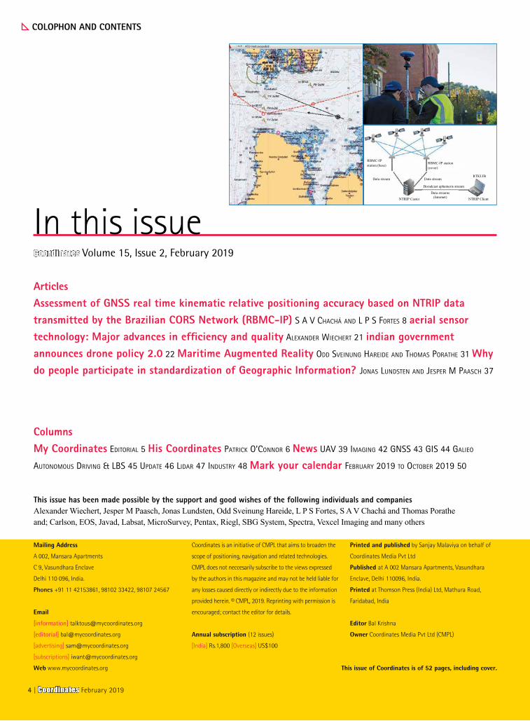
RBMC-IP station (rover)
RBMC-IP station (base)
Data stream Data stream
NTRIP Caster
Data streams(Internet)
Boradcast ephemeris stream
NTRIP Client
RTKLIB
ColumnsMy Coordinates editoriAL 5 His Coordinates PAtriCk o’Connor 6 News uAV 39 imAging 42 gnSS 43 giS 44 gALieo
AutonomouS driVing & LBS 45 uPdAte 46 LidAr 47 induStry 48 Mark your calendar FeBruAry 2019 to oCtoBer 2019 50
This issue of Coordinates is of 52 pages, including cover.
4 | Coordinates February 2019
ADVISORS Naser El-Sheimy PEng, CRC Professor, Department of Geomatics Engineering, The University of Calgary Canada, George
Cho Professor in GIS and the Law, University of Canberra, Australia, Professor Abbas Rajabifard Director, Centre for SDI and Land
Administration, University of Melbourne, Australia, Luiz Paulo Souto Fortes PhD Associate Professor, University of State of Rio Janeiro
(UERJ), Brazil, John Hannah Professor, School of Surveying, University of Otago, New Zealand
MYCOORDINATES
The nature of data are changing
And so are the methods of data gathering.
In this digital era,
Not only our personal information are accumulated, with or without consent
But our behavioral patterns, thought processes, etc. are tracked, documented and exploited.
Benefits of the digital technology are immense
And we happen to be incidental beneficiaries
Yet the world is set to be ruled by those
Who hold these data repositories.
Data colonies are being created
These colonies may appear ‘virtual’.
However, this data imperialism is ‘real’.
Bal Krishna, Editor [email protected]
Data colonies
Coordinates February 2019 | 5
Carlson is continually spreading its excellent software complete with free supportsays, Patrick O’Connor, Australia-Pacific Regional Sales Director, Carlson Software in an interview with Coordinates
HIS COORDINATES
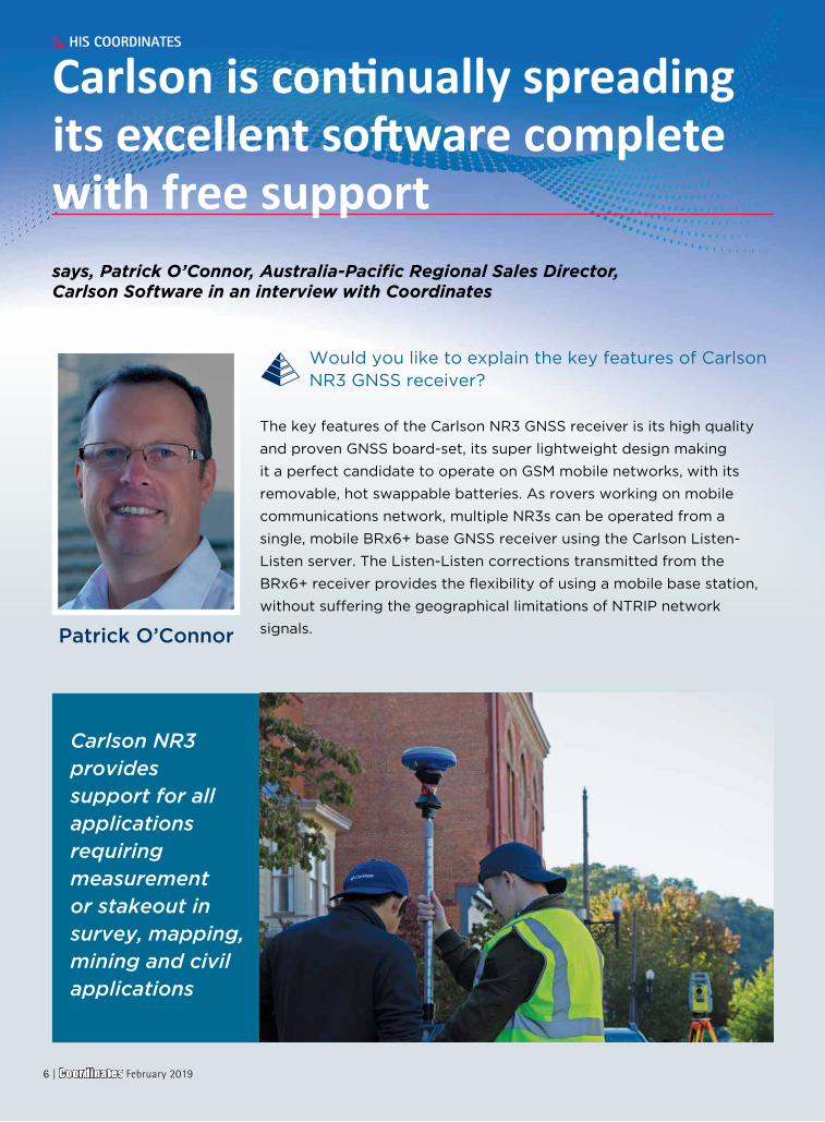
Would you like to explain the key features of Carlson NR3 GNSS receiver?
The key features of the Carlson NR3 GNSS receiver is its high quality
and proven GNSS board-set, its super lightweight design making
it a perfect candidate to operate on GSM mobile networks, with its
removable, hot swappable batteries. As rovers working on mobile
communications network, multiple NR3s can be operated from a
single, mobile BRx6+ base GNSS receiver using the Carlson Listen-
Listen server. The Listen-Listen corrections transmitted from the
BRx6+ receiver provides the flexibility of using a mobile base station,
without suffering the geographical limitations of NTRIP network
signals.Patrick O’Connor
Carlson NR3 provides support for all applications requiring measurement or stakeout in survey, mapping, mining and civil applications
6 | Coordinates February 2019
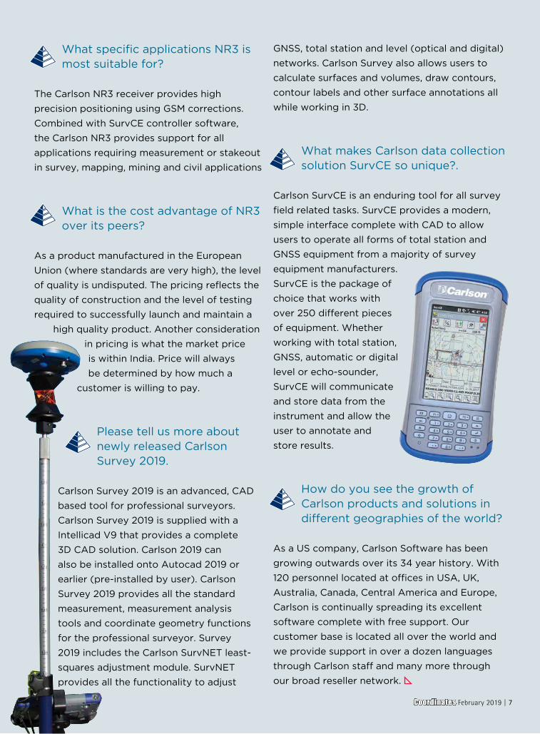
What specific applications NR3 is most suitable for?
The Carlson NR3 receiver provides high
precision positioning using GSM corrections.
Combined with SurvCE controller software,
the Carlson NR3 provides support for all
applications requiring measurement or stakeout
in survey, mapping, mining and civil applications
What is the cost advantage of NR3 over its peers?
As a product manufactured in the European
Union (where standards are very high), the level
of quality is undisputed. The pricing reflects the
quality of construction and the level of testing
required to successfully launch and maintain a
high quality product. Another consideration
in pricing is what the market price
is within India. Price will always
be determined by how much a
customer is willing to pay.
Please tell us more about newly released Carlson Survey 2019.
Carlson Survey 2019 is an advanced, CAD
based tool for professional surveyors.
Carlson Survey 2019 is supplied with a
Intellicad V9 that provides a complete
3D CAD solution. Carlson 2019 can
also be installed onto Autocad 2019 or
earlier (pre-installed by user). Carlson
Survey 2019 provides all the standard
measurement, measurement analysis
tools and coordinate geometry functions
for the professional surveyor. Survey
2019 includes the Carlson SurvNET least-
squares adjustment module. SurvNET
provides all the functionality to adjust
GNSS, total station and level (optical and digital)
networks. Carlson Survey also allows users to
calculate surfaces and volumes, draw contours,
contour labels and other surface annotations all
while working in 3D.
What makes Carlson data collection solution SurvCE so unique?.
Carlson SurvCE is an enduring tool for all survey
field related tasks. SurvCE provides a modern,
simple interface complete with CAD to allow
users to operate all forms of total station and
GNSS equipment from a majority of survey
equipment manufacturers.
SurvCE is the package of
choice that works with
over 250 different pieces
of equipment. Whether
working with total station,
GNSS, automatic or digital
level or echo-sounder,
SurvCE will communicate
and store data from the
instrument and allow the
user to annotate and
store results.
How do you see the growth of Carlson products and solutions in different geographies of the world?
As a US company, Carlson Software has been
growing outwards over its 34 year history. With
120 personnel located at offices in USA, UK,
Australia, Canada, Central America and Europe,
Carlson is continually spreading its excellent
software complete with free support. Our
customer base is located all over the world and
we provide support in over a dozen languages
through Carlson staff and many more through
our broad reseller network.
Coordinates February 2019 | 7
Assessment of GNSS real time kinematic relative positioning accuracyThis work aims to assess real time kinematic relative positioning accuracy based on the Brazilian CORS Network (RBMC-IP). For this, RTKLIB free software was used with an unconventional technique to obtain the observations
GNSS
S A V ChacháDepartment of Cartographic Engineering, Universidade do Estado do Rio de Janeiro, Brazil
L P S FortesDepartment of Cartographic Engineering, Universidade do Estado do Rio de Janeiro, Brazil
In the past decades, Global Navigation Satellite Systems (GNSS) have
revolutionized positioning and navigation activities. Currently, in addition to GPS and GLONASS, developed respectively by the US and Russia (formerly USSR) are fully operational, Galileo, being implemented by the European Union, and BeiDou, by China, expect to reach full operational capabilities around 2020 (FORTES, 2016).
GNSS positioning encompasses several types of users ranging from the average user to professionals and scientists who require a higher level of positioning accuracy, whether static or kinematic. The demand for better precision in real time motivated the development of the relative positioning techniques Real Time Kinematic (RTK) and Differential GNSS (DGNSS), for which there is a need for real-time transmission of observations or corrections to these observations from a known base station to the remote station, whose coordinates are to be determined. Initially, this transmission between the two stations (base and remote) was predominantly established via radio. Other implementations, especially those provided by companies that use networked solutions based on more than one reference station, use communication
satellite data transmission, which substantially increases the solution cost.
Due to the possibility of data transmission via the Internet, existing reach restrictions when using radio link have been overcome, allowing a greater efficiency in surveys where this technique is used. The user can access the Internet using a smartphone and obtain data from one or more base stations provided by a NTRIP Caster server, for example (MONICO, 2008). With the permanent expansion and modernization of the Brazilian Network for Continuous Monitoring of GNSS (RBMC), implemented in Brazil by the Brazilian Institute of Geography and Statistics (IBGE) in partnership with several institutions in the country, data collected at a rate of 1 second in 104 out of 144 stations that currently compose the network are transmitted in real time over the Internet using the Networked Transport of RTCM via Internet Protocol (NTRIP - BKG, 2017a). These 104 stations constitute what is known as the RBMC-IP network (IBGE, 2018).
Data transmission is performed as follows: a GNSS receiver from a reference station continuously sends messages in the RTCM format to a NTRIP Caster server
In this work, an unconventional real-time relative positioning technique was applied,
using only data streams transmitted by RBMC-IP stations to evaluate the quality
of RTK and DGNSS positioning based on data transmitted over the Internet
8 | Coordinates February 2019

DEVELOPED BY SURVEYORS FOR SURVEYORSGet the full tool kit -- from network least squares to surface modeling. Work seamlessly between o�ce and field, create GIS links and exchange Esri® data with Carlson Survey.
Find out more at carlsonsw.com.
Carlson APAC | [email protected] | +61 488 975 088
located at IBGE headquarters. A user with a client application, such as BNC (BKG NTRIP Client - BKG, 2017b) or RTKLIB (TAKASU, 2013), and with an Internet connection connects to the IBGE server and selects RBMC-IP station (s) whose data or differential corrections he/she wishes to receive. These are received by a computer connected to the user’s receiver through a serial or USB port and by this way the corrected positions are obtained (IBGE, 2018). Thus, any user in Brazil with Internet access at a remote station can receive real time data from the nearest RBMC station and perform an RTK positioning, using carrier phase observations, or DGNSS, using pseudoranges. The use of the RBMC-IP infrastructure allows the user to reduce costs, as there is no need to have a pair of receivers to occupy both base and remote stations, besides allowing the establishment of baselines longer than those obtained previously with radios.
DGPS and DGNSS
The DGPS (Differential GPS) technique was developed with the objective of reducing the effects of selective availability imposed on GPS (MONICO, 2008). As this effect greatly depreciated the quality of the coordinates of the satellites and/or the stability of their clocks, compromising the precision of the coordinates obtained, it was necessary to develop a way to increase the accuracy of the determination.
The method is based on the use of a receiver set up at a known coordinate station, tracking the visible satellites, while another receiver occupies the places of interest. The concept is all based on the pseudorange corrections calculated at the reference station and transmitted to the rover station.
This method can provide accuracy in the order of 0.5 to 3m (depending on the length of the baseline), having the ability to perform real-time positioning, although it is also possible to perform post-processing (MONICO, 2008). As with relative positioning techniques, the DGPS technique is directly affected
by the baseline length, degrading its accuracy as it increases (FORTES, 2016).
The emergence of other GNSS systems besides GPS improved the quality of the positioning, due to the fact that more constellations of satellites are available for tracking, providing more observations, which contributes to the improvement of the geometry of the solution (FERREIRA and FORTES, 2016). Thus the DGNSS technique is based on the same concept of the DGPS technique, but using other constellations besides GPS to perform the positioning.
Real-time kinematic (RTK) relative positioning
The real-time kinematic (RTK) relative positioning technique is based on the use of carrier phase - and code (pseudorange) – observations measured from the signals transmitted by GNSS satellites. Analogously to DGNSS, it is also based on the transmission of data collected at a reference station (base) to the rover station through a link that can employ modem using radio waves, or through GSM technology or any other system of communication (MONICO, 2008). The receiver of the rover station must usually have appropriate software for performing the data processing in real time. The purpose of the RTK technique is to obtain coordinates with good accuracy (i.e., centimeter) instantly, without the need for post-processing of data.
According to Seeber (2003), RTK technology is based on the following characteristics:• Real-time transmission of carrier
phase and pseudorange data from the base station to the rover station or corrections thereto;
• Resolution of the ambiguities as integers almost in real time (on the way or on the fly), allowing the accuracy to reach the centimetric level;
• Reliable determination of the baseline vector in real time or near real time.
The RTK technique has great advantages over conventional topography techniques
because it has good real-time precision and is highly productive. However, there are limitations when using the more traditional methodology of VHF/UHF radio waves for communication between receivers. These limitations occur in heavily obstructed environments (vegetation and buildings), which reduces the reach of the radio link that transmits differential corrections.
On the other hand, the significant technological advance in the last decades, especially in the use of the Internet in mobile systems, made possible a great transformation in RTK applications. Due to the possibility of data transmission via the Internet, the restrictions that exist when using the radio link are overcome, making possible a greater efficiency in the surveys where this technique is used. The user can access the Internet using a smartphone and obtain data from a NTRIP Caster server, for example (MONICO, 2008).
Because of its real-time capabilities, this technique has a variety of applications, among which it is worth mentioning: precision agriculture, mining, construction, topography, navigation, among others. Therefore, this technique is widely used, being one of the most advanced in the current state of the art of GNSS positioning.
Ambiguity vector solution
When discussing relative positioning, one issue that is extremely important is the solution of the vector of ambiguities. For real-time kinematic applications, it is of fundamental importance to quickly resolve the ambiguities, allowing the estimation of the whole numbers of cycles.
The effects of ionospheric and tropospheric refraction, multipath and other unmodeled errors, as well as the geometry and number of satellites, affect the solution of ambiguities. Another important aspect is the duration of the observation session. The contribution of carrier phase observations in this process is a function of time, being directly correlated to the satellites movement (MONICO, 2008).
10 | Coordinates February 2019
In general, the solution of the vector of ambiguities is classified into two types: floating solution (Float) and fixed solution (Fixed). In the first one the ambiguities are determined in the least squares adjustment or in the Kalman Filter as Real numbers (ℜ). The fixed solution is obtained by determining the ambiguities of the satellites as integer values, obtaining, in this way, high precision (FORTES, 2016).
Study area
This project was carried out using RBMC-IP stations described in Table 1.
The two baselines have the following lengths: 10 km for SAVO-SSA1 and 82 km for SJSP-UBA1.
Equipment and programs used
The equipment used in RTK and DGNSS techniques generally comes complete in terms of hardware and software for this purpose. In this work, however, the conventional configuration used in this method was not used, where the rover receiver receives the data from the reference station by means of radio or other form of communication and the positioning solution is usually generated at that station.
All the surveys were carried out in this work using data streams transmitted by the those four RBMC-IP stations and received via the Internet by the RTKLIB software. Version 2.4.2_p12 of this software was installed and operated on a notebook with Windows operating system with broadband Internet connection, through which all kinematic processing was performed in real time, reproducing the type of survey that is performed in a conventional manner.
RTKLIB
RTKLIB software is a free, open source software package for real-time or post-processed GNSS positioning developed by Tomoji Takasu. This package consists of several programs and a library that can be used in the development of programs for processing GNSS data (TAKASU, 2013). For this research, the RTKNAVI program, the RTKLIB software package component responsible for real-time processing, was used.
Methodology
As previously indicated, in this work two stations of the RBMC-IP were considered, one as a rover station and the other as a base station, both transmitting over the Internet the data streams that were received and processed in the kinematic mode by RTKNAVI. By this way it was possible to compare the coordinates obtained for the station considered rover and those of reference, allowing the determination of the positioning accuracy.
In RTKNAVI, it was necessary to select the stations data streams, frequency and the positioning technique to be used. For other options, such as a priori errors of phase and code observations, etc., the default values were not changed to evaluate the quality of the results that would be obtained by the beginning user.
In this research, the two baselines used were processed totalizing 24 observation sessions, divided as follows: two RTK surveys in two observation periods, with sessions between 14:00 and 18:00 (11:00 a.m. 15:00) and between 18:00 and 23:00 (15:00 and 20:00) hours, GPS time (local time), with an hour each, to evaluate the quality of the positioning under various ionospheric conditions; additionally, a DGNSS survey with a two-hour duration between 14:00 and 01:00 (11:00 and 22:00) hours, GPS time (local time). All solutions were obtained in kinematic mode.
For each baseline, the variations of GNSS systems and frequencies were used for both RTK and the DGNSS techniques, as shown in table 2.
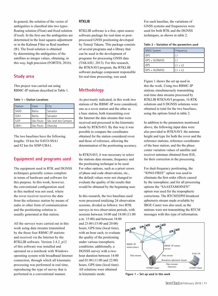
Figure 1 shows the set up used in this the work. Using two RBMC-IP stations simultaneously transmitting real-time data streams processed by RTKLIB RTKNAVI program, 16 RTK solutions and 8 DGNSS solutions were obtained in total for the two baselines, using the options listed in table 2.
In addition to the parameters mentioned above, the following input data were also provided to RTKNAVI: the antenna height and type for both the rover and the reference stations; reference coordinates of the base station; and the the phase center variation values of satellite and receiver antennas obtained from IGS, for their correction in the processing.
For dual-frequency positioning, the “IONO-FREE” option was used to eliminate the first order effects caused by the ionosphere; and for all processing options the “SAASTAMOINEN” option was used for the tropospheric corrections. The RTCM3EPH broadcast ephemeris stream made available by IBGE Caster was also used, as the stations were not transmitting the RTCM messages with this type of information.
RBMC-IP station (rover)
RBMC-IP station (base)
Data stream Data stream
NTRIP Caster
Data streams(Internet)
Boradcast ephemeris stream
NTRIP Client
RTKLIB
Figure 1 – Set up used in this work
Table 2 - Variation of the parameters used
GNSS System Frequency
GPS L1
GPS + GLONASS L1
GPS L1 + L2
GPS + GLONASS L1 + L2
Table 1 - Station Locations
Station State City
SAVO Bahia Salvador
SSA1 Bahia Salvador
SJSP São Paulo São José dos Campos
UBA1 São Paulo Ubatuba
Coordinates February 2019 | 11
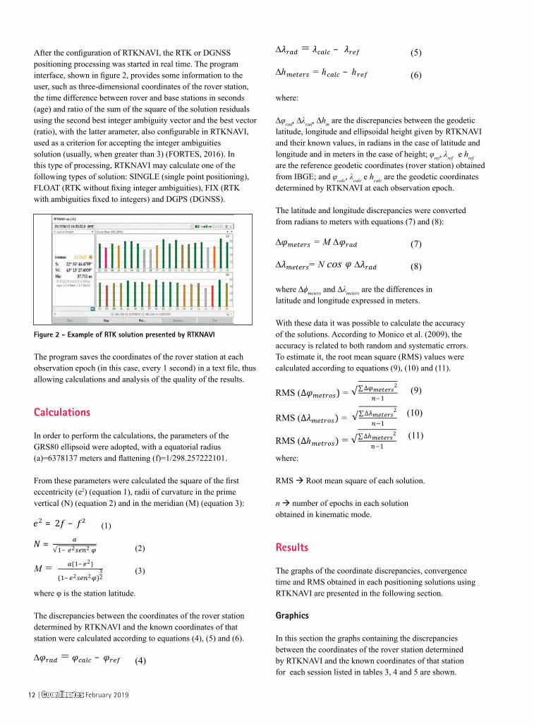
After the configuration of RTKNAVI, the RTK or DGNSS positioning processing was started in real time. The program interface, shown in figure 2, provides some information to the user, such as three-dimensional coordinates of the rover station, the time difference between rover and base stations in seconds (age) and ratio of the sum of the square of the solution residuals using the second best integer ambiguity vector and the best vector (ratio), with the latter arameter, also configurable in RTKNAVI, used as a criterion for accepting the integer ambiguities solution (usually, when greater than 3) (FORTES, 2016). In this type of processing, RTKNAVI may calculate one of the following types of solution: SINGLE (single point positioning), FLOAT (RTK without fixing integer ambiguities), FIX (RTK with ambiguities fixed to integers) and DGPS (DGNSS).
The program saves the coordinates of the rover station at each observation epoch (in this case, every 1 second) in a text file, thus allowing calculations and analysis of the quality of the results.
Calculations
In order to perform the calculations, the parameters of the GRS80 ellipsoid were adopted, with a equatorial radius (a)=6378137 meters and flattening (f)=1/298.257222101.
From these parameters were calculated the square of the first eccentricity (e2) (equation 1), radii of curvature in the prime vertical (N) (equation 2) and in the meridian (M) (equation 3):
(1)
(2)
(3)
where φ is the station latitude.
The discrepancies between the coordinates of the rover station determined by RTKNAVI and the known coordinates of that station were calculated according to equations (4), (5) and (6).
(4)
(5)
(6)
where:
∆φrad, ∆λrad, ∆hm are the discrepancies between the geodetic latitude, longitude and ellipsoidal height given by RTKNAVI and their known values, in radians in the case of latitude and longitude and in meters in the case of height; φref, λref e href are the reference geodetic coordinates (rover station) obtained from IBGE; and φcalc, λcalc e hcalc are the geodetic coordinates determined by RTKNAVI at each observation epoch.
The latitude and longitude discrepancies were converted from radians to meters with equations (7) and (8):
(7)
(8)
where ∆ϕmeters and ∆λmeters are the differences in latitude and longitude expressed in meters.
With these data it was possible to calculate the accuracy of the solutions. According to Monico et al. (2009), the accuracy is related to both random and systematic errors. To estimate it, the root mean square (RMS) values were calculated according to equations (9), (10) and (11).
(9)
(10)
(11)
where:
RMS Root mean square of each solution.
n number of epochs in each solution obtained in kinematic mode.
Results
The graphs of the coordinate discrepancies, convergence time and RMS obtained in each positioning solutions using RTKNAVI are presented in the following section.
Graphics
In this section the graphs containing the discrepancies between the coordinates of the rover station determined by RTKNAVI and the known coordinates of that station for each session listed in tables 3, 4 and 5 are shown.
Figure 2 - Example of RTK solution presented by RTKNAVI
12 | Coordinates February 2019
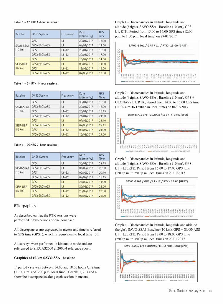
Table 3 - 1st RTK 1-hour sessions
Baseline GNSS System FrequencyDate(dd/mm/yy)
GPS Time
SAVO-SSA1 (10 km)
GPS L1 29/01/2017 15:00
GPS+GLONASS L1 04/02/2017 14:00
GPS L1+L2 29/01/2017 16:00
GPS+GLONASS L1+L2 29/01/2017 17:00
SJSP-UBA1 (82 km)
GPS L1 18/02/2017 14:00
GPS+GLONASS L1 08/07/2017 14:30
GPS L1+L2 18/02/2017 16:00
GPS+GLONASS L1+L2 07/06/2017 17:30
Table 4 - 2nd RTK 1-hour sessions
Baseline GNSS System FrequencyDate(dd/mm/yy)
GPS Time
SAVO-SSA1 (10 km)
GPS L1 30/01/2017 19:00
GPS+GLONASS L1 29/01/2017 18:00
GPS L1+L2 25/01/2017 18:15
GPS+GLONASS L1+L2 24/01/2017 21:00
SJSP-UBA1 (82 km)
GPS L1 07/06/2017 21:10
GPS+GLONASS L1 07/06/2017 22:11
GPS L1+L2 03/07/2017 21:30
GPS+GLONASS L1+L2 16/02/2017 21:00
Table 5 - DGNSS 2-hour sessions
Baseline GNSS System FrequencyDate(dd/mm/yy)
GPS Time
SAVO-SSA1 (10 km)
GPS L1 30/01/2017 22:15
GPS+GLONASS L1 01/02/2017 20:00
GPS L1+L2 02/02/2017 20:10
GPS+GLONASS L1+L2 02/02/2017 18:15
SJSP-UBA1 (82 km)
GPS L1 21/02/2017 14:30
GPS+GLONASS L1 22/02/2017 23:00
GPS L1+L2 23/02/2017 23:00
GPS+GLONASS L1+L2 03/03/2017 22:00
RTK graphics
As described earlier, the RTK sessions were performed in two periods of one hour each.
All discrepancies are expressed in meters and time is referred to GPS time (GPST), which is requivalent to local time +3h.
All surveys were performed in kinematic mode and are referenced to SIRGAS2000 at 2000.4 reference epoch.
Graphics of 10-km SAVO-SSA1 baseline
1st period - surveys between 14:00 and 18:00 hours GPS time (11:00 a.m. and 3:00 p.m. local time). Graphs 1, 2, 3 and 4 show the discrepancies along each session in meters.
Graph 1 - Discrepancies in latitude, longitude and altitude (height). SAVO-SSA1 Baseline (10 km), GPS L1, RTK, Period from 15:00 to 16:00 GPS time (12:00 p.m. to 1:00 p.m. local time) on 29/01/2017
Graph 2 - Discrepancies in latitude, longitude and altitude (height). SAVO-SSA1 Baseline (10 km), GPS + GLONASS L1, RTK, Period from 14:00 to 15:00 GPS time (11:00 a.m. to 12:00 p.m. local time) on 04/02/2017
Graph 3 - Discrepancies in latitude, longitude and altitude (height). SAVO-SSA1 Baseline (10 km), GPS L1 + L2, RTK, Period from 16:00 to 17:00 GPS time (1:00 p.m. to 2:00 p.m. local time) on 29/01/2017
Graph 4 - Discrepancies in latitude, longitude and altitude (height). SAVO-SSA1 Baseline (10 km), GPS + GLONASS L1 + L2, RTK, Period from 17:00 to 18:00 GPS time (2:00 p.m. to 3:00 p.m. local time) on 29/01 2017
Coordinates February 2019 | 13
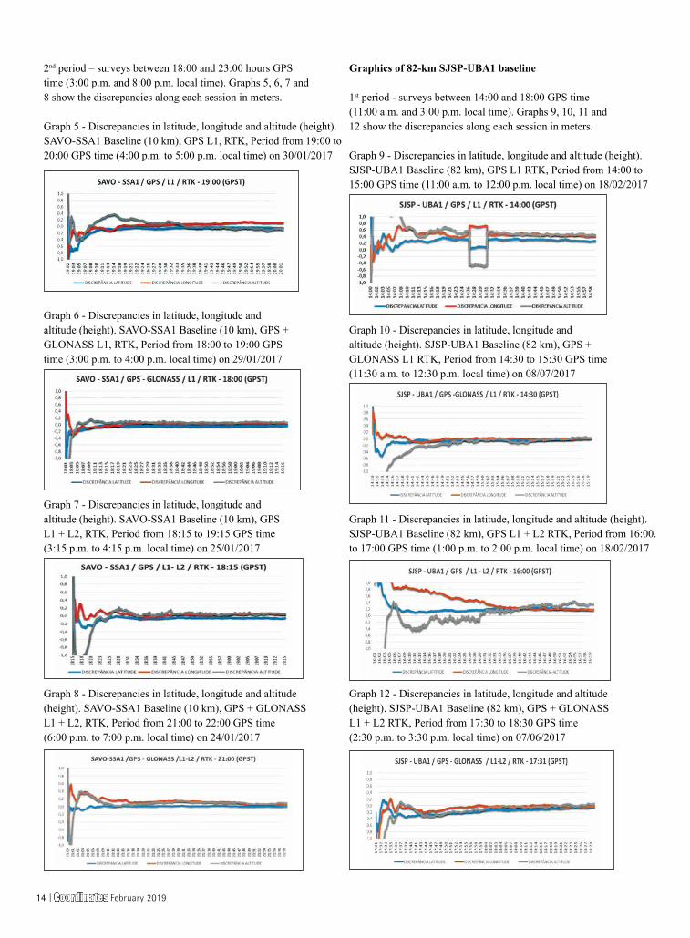
2nd period – surveys between 18:00 and 23:00 hours GPS time (3:00 p.m. and 8:00 p.m. local time). Graphs 5, 6, 7 and 8 show the discrepancies along each session in meters.
Graph 5 - Discrepancies in latitude, longitude and altitude (height). SAVO-SSA1 Baseline (10 km), GPS L1, RTK, Period from 19:00 to 20:00 GPS time (4:00 p.m. to 5:00 p.m. local time) on 30/01/2017
Graph 6 - Discrepancies in latitude, longitude and altitude (height). SAVO-SSA1 Baseline (10 km), GPS + GLONASS L1, RTK, Period from 18:00 to 19:00 GPS time (3:00 p.m. to 4:00 p.m. local time) on 29/01/2017
Graph 7 - Discrepancies in latitude, longitude and altitude (height). SAVO-SSA1 Baseline (10 km), GPS L1 + L2, RTK, Period from 18:15 to 19:15 GPS time (3:15 p.m. to 4:15 p.m. local time) on 25/01/2017
Graph 8 - Discrepancies in latitude, longitude and altitude (height). SAVO-SSA1 Baseline (10 km), GPS + GLONASS L1 + L2, RTK, Period from 21:00 to 22:00 GPS time (6:00 p.m. to 7:00 p.m. local time) on 24/01/2017
Graphics of 82-km SJSP-UBA1 baseline
1st period - surveys between 14:00 and 18:00 GPS time (11:00 a.m. and 3:00 p.m. local time). Graphs 9, 10, 11 and 12 show the discrepancies along each session in meters.
Graph 9 - Discrepancies in latitude, longitude and altitude (height). SJSP-UBA1 Baseline (82 km), GPS L1 RTK, Period from 14:00 to 15:00 GPS time (11:00 a.m. to 12:00 p.m. local time) on 18/02/2017
Graph 10 - Discrepancies in latitude, longitude and altitude (height). SJSP-UBA1 Baseline (82 km), GPS + GLONASS L1 RTK, Period from 14:30 to 15:30 GPS time (11:30 a.m. to 12:30 p.m. local time) on 08/07/2017
Graph 11 - Discrepancies in latitude, longitude and altitude (height). SJSP-UBA1 Baseline (82 km), GPS L1 + L2 RTK, Period from 16:00. to 17:00 GPS time (1:00 p.m. to 2:00 p.m. local time) on 18/02/2017
Graph 12 - Discrepancies in latitude, longitude and altitude (height). SJSP-UBA1 Baseline (82 km), GPS + GLONASS L1 + L2 RTK, Period from 17:30 to 18:30 GPS time (2:30 p.m. to 3:30 p.m. local time) on 07/06/2017
14 | Coordinates February 2019
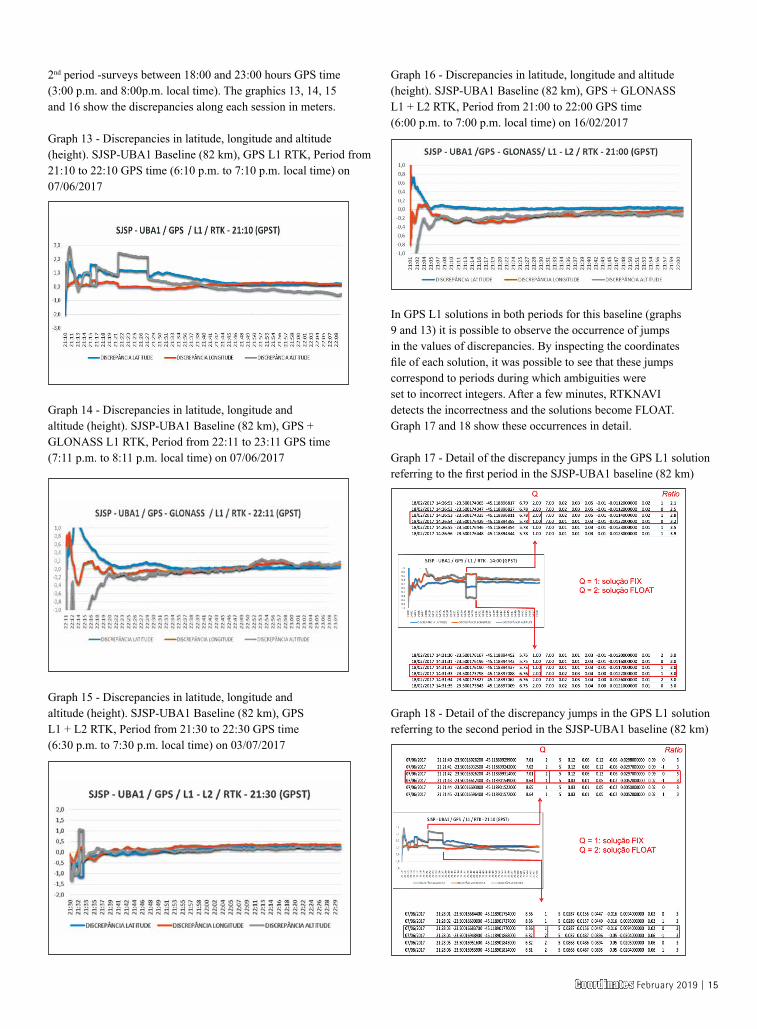
2nd period -surveys between 18:00 and 23:00 hours GPS time (3:00 p.m. and 8:00p.m. local time). The graphics 13, 14, 15 and 16 show the discrepancies along each session in meters.
Graph 13 - Discrepancies in latitude, longitude and altitude (height). SJSP-UBA1 Baseline (82 km), GPS L1 RTK, Period from 21:10 to 22:10 GPS time (6:10 p.m. to 7:10 p.m. local time) on 07/06/2017
Graph 14 - Discrepancies in latitude, longitude and altitude (height). SJSP-UBA1 Baseline (82 km), GPS + GLONASS L1 RTK, Period from 22:11 to 23:11 GPS time (7:11 p.m. to 8:11 p.m. local time) on 07/06/2017
Graph 15 - Discrepancies in latitude, longitude and altitude (height). SJSP-UBA1 Baseline (82 km), GPS L1 + L2 RTK, Period from 21:30 to 22:30 GPS time (6:30 p.m. to 7:30 p.m. local time) on 03/07/2017
Graph 16 - Discrepancies in latitude, longitude and altitude (height). SJSP-UBA1 Baseline (82 km), GPS + GLONASS L1 + L2 RTK, Period from 21:00 to 22:00 GPS time (6:00 p.m. to 7:00 p.m. local time) on 16/02/2017
In GPS L1 solutions in both periods for this baseline (graphs 9 and 13) it is possible to observe the occurrence of jumps in the values of discrepancies. By inspecting the coordinates file of each solution, it was possible to see that these jumps correspond to periods during which ambiguities were set to incorrect integers. After a few minutes, RTKNAVI detects the incorrectness and the solutions become FLOAT. Graph 17 and 18 show these occurrences in detail.
Graph 17 - Detail of the discrepancy jumps in the GPS L1 solution referring to the first period in the SJSP-UBA1 baseline (82 km)
Graph 18 - Detail of the discrepancy jumps in the GPS L1 solution referring to the second period in the SJSP-UBA1 baseline (82 km)
Coordinates February 2019 | 15
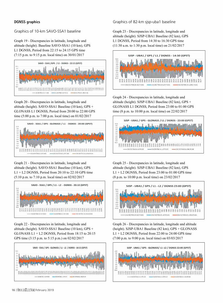
DGNSS graphics
Graphics of 10-km SAVO-SSA1 baseline
Graph 19 - Discrepancies in latitude, longitude and altitude (height). Baseline SAVO-SSA1 (10 km), GPS L1 DGNSS, Period from 22:15 to 24:15 GPS time (7:15 p.m. to 9:15 p.m. local time) on 30/01/2017
Graph 20 - Discrepancies in latitude, longitude and altitude (height). SAVO-SSA1 Baseline (10 km), GPS + GLONASS L1 DGNSS, Period from 20:00 to 22:00 GPS time (5:00 p.m. to 7:00 p.m. local time) on 01/02/2017
Graph 21 - Discrepancies in latitude, longitude and altitude (height). SAVO-SSA1 Baseline (10 km), GPS L1 + L2 DGNSS, Period from 20:10 to 22:10 GPS time (5:10 p.m. to 7:10 p.m. local time) on 02/02/2017
Graph 22 - Discrepancies in latitude, longitude and altitude (height). SAVO-SSA1 Baseline (10 km), GPS + GLONASS L1 + L2 DGNSS, Period from 18:15 to 20:15 GPS time (3:15 p.m. to 5:15 p.m.) on 02/02/2017
Graphics of 82-km sjsp-uba1 baseline
Graph 23 - Discrepancies in latitude, longitude and altitude (height). SJSP-UBA1 Baseline (82 km), GPS L1 DGNSS, Period from 14:30 to 16:30 GPS time (11:30 a.m. to 1:30 p.m. local time) on 21/02/2017
Graph 24 - Discrepancies in latitude, longitude and altitude (height). SJSP-UBA1 Baseline (82 km), GPS + GLONASS L1 DGNSS, Period from 23:00 to 01:00 GPS time (8 p.m. to 10:00 p.m. local time) on 22/02/2017
Graph 25 - Discrepancies in latitude, longitude and altitude (height). SJSP-UBA1 Baseline (82 km), GPS L1 + L2 DGNSS, Period from 23:00 to 01:00 GPS time (8 p.m. to 10:00 p.m. local time) on 23/02/2017
Graph 26 - Discrepancies in latitude, longitude and altitude (height). SJSP-UBA1 Baseline (82 km), GPS + GLONASS L1 + L2 DGNSS, Period from 22:00 to 24:00 GPS time (7:00 p.m. to 9:00 p.m. local time) on 03/03/2017
16 | Coordinates February 2019
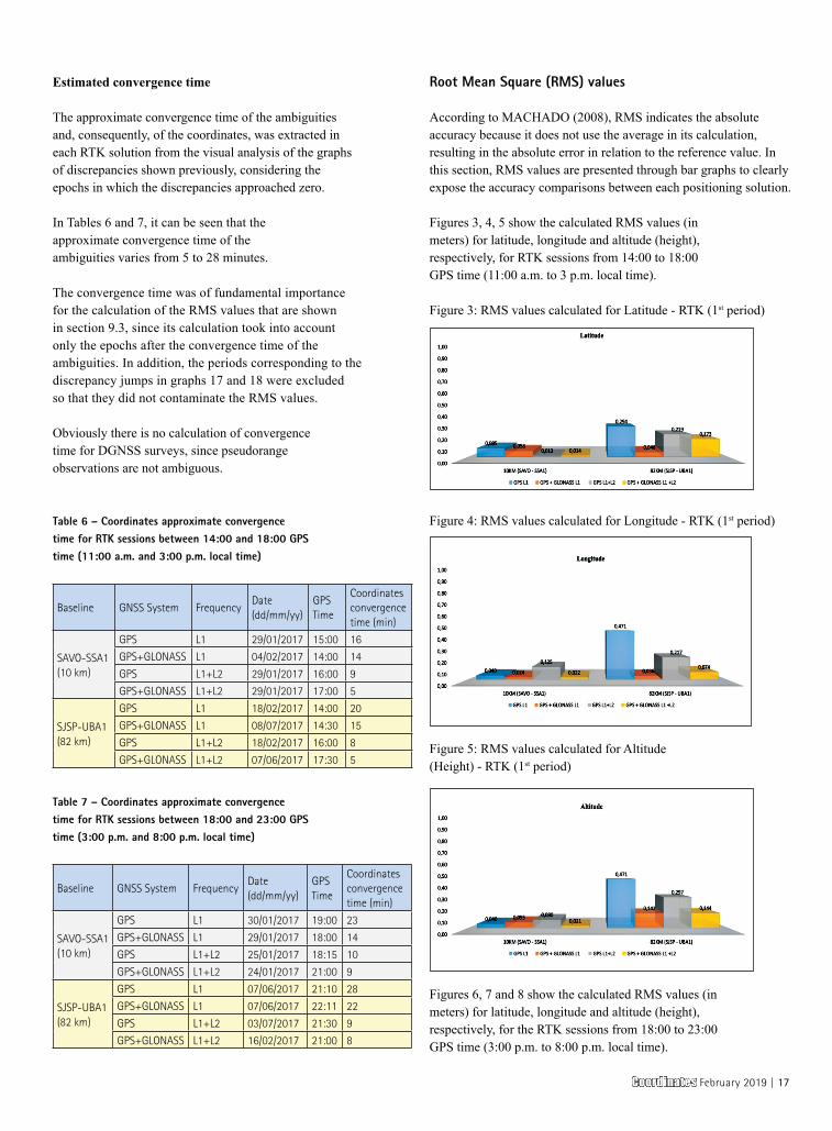
Estimated convergence time
The approximate convergence time of the ambiguities and, consequently, of the coordinates, was extracted in each RTK solution from the visual analysis of the graphs of discrepancies shown previously, considering the epochs in which the discrepancies approached zero.
In Tables 6 and 7, it can be seen that the approximate convergence time of the ambiguities varies from 5 to 28 minutes.
The convergence time was of fundamental importance for the calculation of the RMS values that are shown in section 9.3, since its calculation took into account only the epochs after the convergence time of the ambiguities. In addition, the periods corresponding to the discrepancy jumps in graphs 17 and 18 were excluded so that they did not contaminate the RMS values.
Obviously there is no calculation of convergence time for DGNSS surveys, since pseudorange observations are not ambiguous.
Table 6 – Coordinates approximate convergence time for RTK sessions between 14:00 and 18:00 GPS time (11:00 a.m. and 3:00 p.m. local time)
Baseline GNSS System FrequencyDate(dd/mm/yy)
GPS Time
Coordinates convergence time (min)
SAVO-SSA1 (10 km)
GPS L1 29/01/2017 15:00 16
GPS+GLONASS L1 04/02/2017 14:00 14
GPS L1+L2 29/01/2017 16:00 9
GPS+GLONASS L1+L2 29/01/2017 17:00 5
SJSP-UBA1 (82 km)
GPS L1 18/02/2017 14:00 20
GPS+GLONASS L1 08/07/2017 14:30 15
GPS L1+L2 18/02/2017 16:00 8
GPS+GLONASS L1+L2 07/06/2017 17:30 5
Table 7 – Coordinates approximate convergence time for RTK sessions between 18:00 and 23:00 GPS time (3:00 p.m. and 8:00 p.m. local time)
Baseline GNSS System FrequencyDate(dd/mm/yy)
GPS Time
Coordinates convergence time (min)
SAVO-SSA1 (10 km)
GPS L1 30/01/2017 19:00 23
GPS+GLONASS L1 29/01/2017 18:00 14
GPS L1+L2 25/01/2017 18:15 10
GPS+GLONASS L1+L2 24/01/2017 21:00 9
SJSP-UBA1 (82 km)
GPS L1 07/06/2017 21:10 28
GPS+GLONASS L1 07/06/2017 22:11 22
GPS L1+L2 03/07/2017 21:30 9
GPS+GLONASS L1+L2 16/02/2017 21:00 8
Root Mean Square (RMS) values
According to MACHADO (2008), RMS indicates the absolute accuracy because it does not use the average in its calculation, resulting in the absolute error in relation to the reference value. In this section, RMS values are presented through bar graphs to clearly expose the accuracy comparisons between each positioning solution.
Figures 3, 4, 5 show the calculated RMS values (in meters) for latitude, longitude and altitude (height), respectively, for RTK sessions from 14:00 to 18:00 GPS time (11:00 a.m. to 3 p.m. local time).
Figure 3: RMS values calculated for Latitude - RTK (1st period)
Figure 4: RMS values calculated for Longitude - RTK (1st period)
Figure 5: RMS values calculated for Altitude (Height) - RTK (1st period)
Figures 6, 7 and 8 show the calculated RMS values (in meters) for latitude, longitude and altitude (height), respectively, for the RTK sessions from 18:00 to 23:00 GPS time (3:00 p.m. to 8:00 p.m. local time).
Coordinates February 2019 | 17
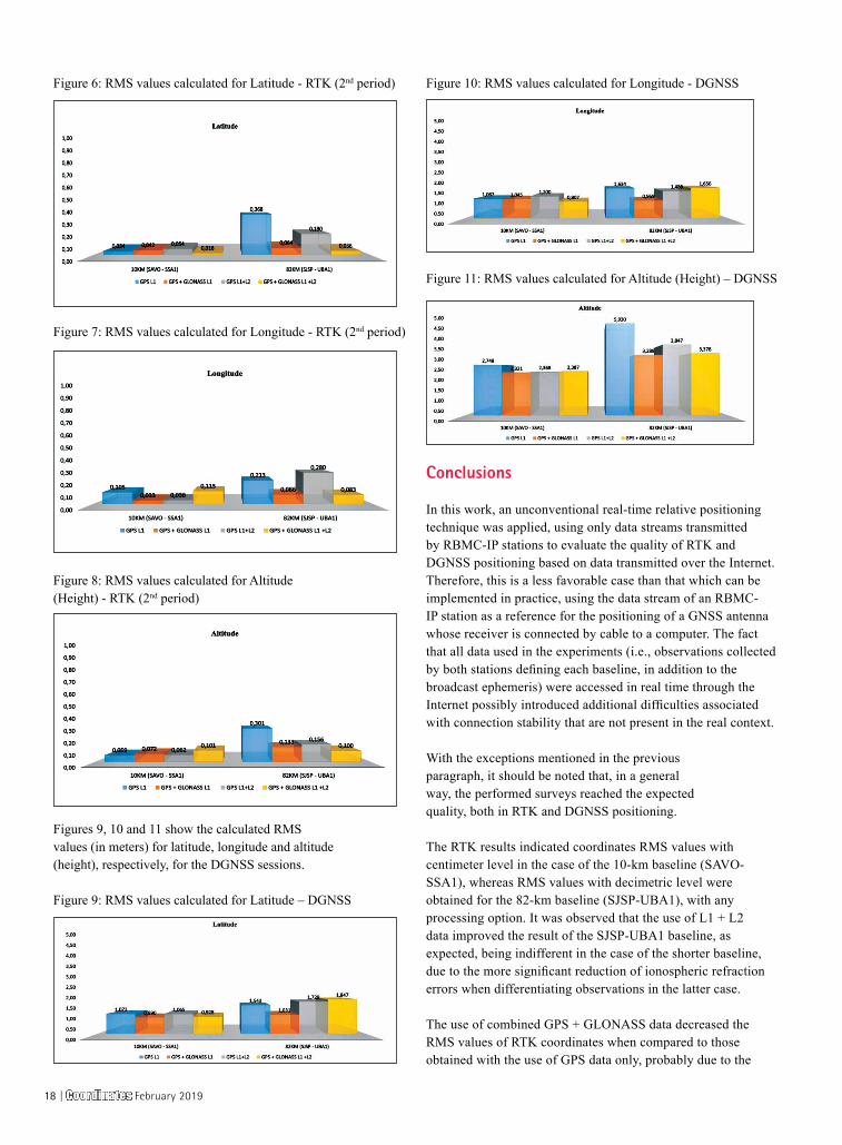
Figure 6: RMS values calculated for Latitude - RTK (2nd period)
Figure 7: RMS values calculated for Longitude - RTK (2nd period)
Figure 8: RMS values calculated for Altitude (Height) - RTK (2nd period)
Figures 9, 10 and 11 show the calculated RMS values (in meters) for latitude, longitude and altitude (height), respectively, for the DGNSS sessions.
Figure 9: RMS values calculated for Latitude – DGNSS
Figure 10: RMS values calculated for Longitude - DGNSS
Figure 11: RMS values calculated for Altitude (Height) – DGNSS
Conclusions
In this work, an unconventional real-time relative positioning technique was applied, using only data streams transmitted by RBMC-IP stations to evaluate the quality of RTK and DGNSS positioning based on data transmitted over the Internet. Therefore, this is a less favorable case than that which can be implemented in practice, using the data stream of an RBMC-IP station as a reference for the positioning of a GNSS antenna whose receiver is connected by cable to a computer. The fact that all data used in the experiments (i.e., observations collected by both stations defining each baseline, in addition to the broadcast ephemeris) were accessed in real time through the Internet possibly introduced additional difficulties associated with connection stability that are not present in the real context.
With the exceptions mentioned in the previous paragraph, it should be noted that, in a general way, the performed surveys reached the expected quality, both in RTK and DGNSS positioning.
The RTK results indicated coordinates RMS values with centimeter level in the case of the 10-km baseline (SAVO-SSA1), whereas RMS values with decimetric level were obtained for the 82-km baseline (SJSP-UBA1), with any processing option. It was observed that the use of L1 + L2 data improved the result of the SJSP-UBA1 baseline, as expected, being indifferent in the case of the shorter baseline, due to the more significant reduction of ionospheric refraction errors when differentiating observations in the latter case.
The use of combined GPS + GLONASS data decreased the RMS values of RTK coordinates when compared to those obtained with the use of GPS data only, probably due to the
18 | Coordinates February 2019
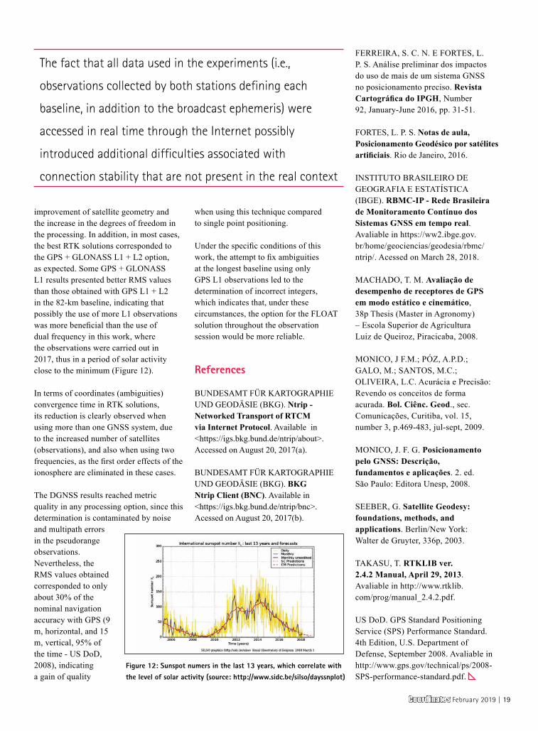
improvement of satellite geometry and the increase in the degrees of freedom in the processing. In addition, in most cases, the best RTK solutions corresponded to the GPS + GLONASS L1 + L2 option, as expected. Some GPS + GLONASS L1 results presented better RMS values than those obtained with GPS L1 + L2 in the 82-km baseline, indicating that possibly the use of more L1 observations was more beneficial than the use of dual frequency in this work, where the observations were carried out in 2017, thus in a period of solar activity close to the minimum (Figure 12).
In terms of coordinates (ambiguities) convergence time in RTK solutions, its reduction is clearly observed when using more than one GNSS system, due to the increased number of satellites (observations), and also when using two frequencies, as the first order effects of the ionosphere are eliminated in these cases.
The DGNSS results reached metric quality in any processing option, since this determination is contaminated by noise and multipath errors in the pseudorange observations. Nevertheless, the RMS values obtained corresponded to only about 30% of the nominal navigation accuracy with GPS (9 m, horizontal, and 15 m, vertical, 95% of the time - US DoD, 2008), indicating a gain of quality
when using this technique compared to single point positioning.
Under the specific conditions of this work, the attempt to fix ambiguities at the longest baseline using only GPS L1 observations led to the determination of incorrect integers, which indicates that, under these circumstances, the option for the FLOAT solution throughout the observation session would be more reliable.
References
BUNDESAMT FÜR KARTOGRAPHIE UND GEODÄSIE (BKG). Ntrip - Networked Transport of RTCM via Internet Protocol. Available in <https://igs.bkg.bund.de/ntrip/about>. Accessed on August 20, 2017(a).
BUNDESAMT FÜR KARTOGRAPHIE UND GEODÄSIE (BKG). BKG Ntrip Client (BNC). Available in <https://igs.bkg.bund.de/ntrip/bnc>. Acessed on August 20, 2017(b).
FERREIRA, S. C. N. E FORTES, L. P. S. Análise preliminar dos impactos do uso de mais de um sistema GNSS no posicionamento preciso. Revista Cartográfica do IPGH, Number 92, January-June 2016, pp. 31-51.
FORTES, L. P. S. Notas de aula, Posicionamento Geodésico por satélites artificiais. Rio de Janeiro, 2016.
INSTITUTO BRASILEIRO DE GEOGRAFIA E ESTATÍSTICA (IBGE). RBMC-IP - Rede Brasileira de Monitoramento Contínuo dos Sistemas GNSS em tempo real. Avaliable in https://ww2.ibge.gov.br/home/geociencias/geodesia/rbmc/ntrip/. Acessed on March 28, 2018.
MACHADO, T. M. Avaliação de desempenho de receptores de GPS em modo estático e cinemático, 38p Thesis (Master in Agronomy) – Escola Superior de Agricultura Luiz de Queiroz, Piracicaba, 2008.
MONICO, J F.M.; PÓZ, A.P.D.; GALO, M.; SANTOS, M.C.; OLIVEIRA, L.C. Acurácia e Precisão: Revendo os conceitos de forma acurada. Bol. Ciênc. Geod., sec. Comunicações, Curitiba, vol. 15, number 3, p.469-483, jul-sept, 2009.
MONICO, J. F. G. Posicionamento pelo GNSS: Descrição, fundamentos e aplicações. 2. ed. São Paulo: Editora Unesp, 2008.
SEEBER, G. Satellite Geodesy: foundations, methods, and applications. Berlin/New York: Walter de Gruyter, 336p, 2003.
TAKASU, T. RTKLIB ver. 2.4.2 Manual, April 29, 2013. Avaliable in http://www.rtklib.com/prog/manual_2.4.2.pdf.
US DoD. GPS Standard Positioning Service (SPS) Performance Standard. 4th Edition, U.S. Department of Defense, September 2008. Avaliable in http://www.gps.gov/technical/ps/2008-SPS-performance-standard.pdf.
Figure 12: Sunspot numers in the last 13 years, which correlate with the level of solar activity (source: http://www.sidc.be/silso/dayssnplot)
The fact that all data used in the experiments (i.e.,
observations collected by both stations defining each
baseline, in addition to the broadcast ephemeris) were
accessed in real time through the Internet possibly
introduced additional difficulties associated with
connection stability that are not present in the real context
Coordinates February 2019 | 19
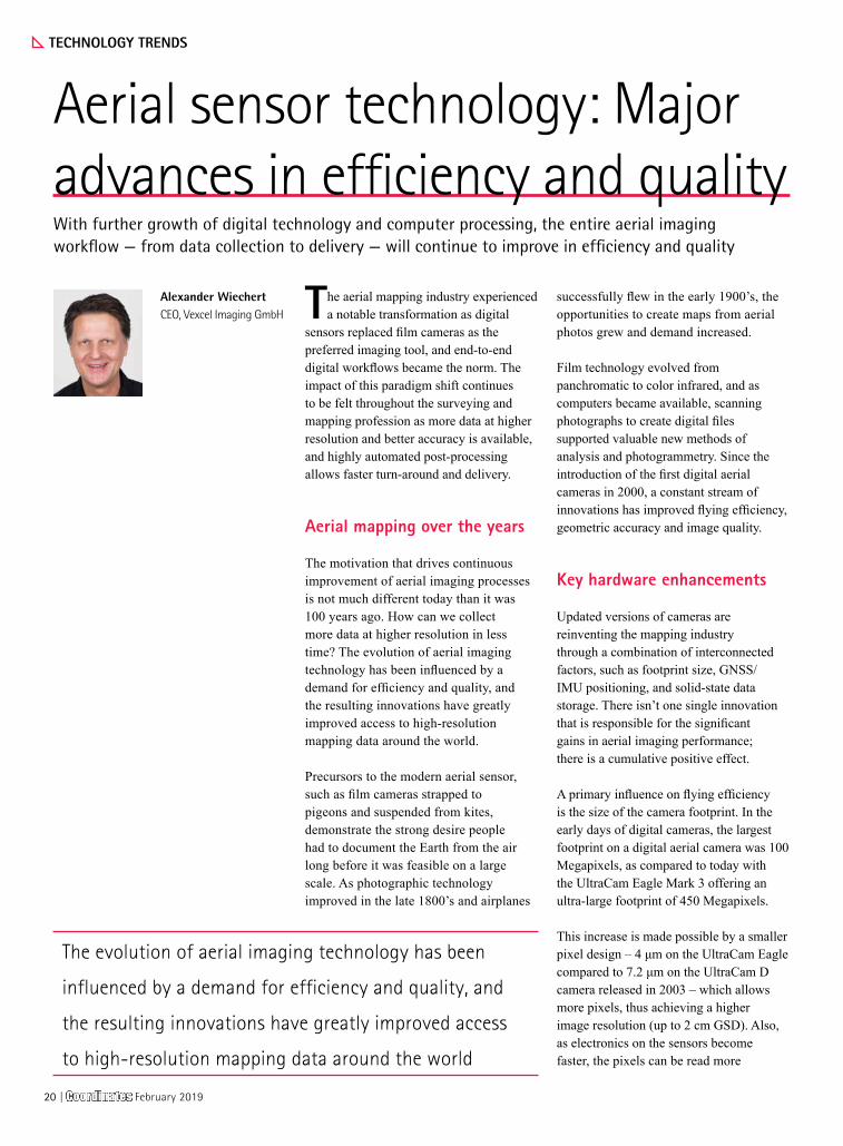
The aerial mapping industry experienced a notable transformation as digital
sensors replaced film cameras as the preferred imaging tool, and end-to-end digital workflows became the norm. The impact of this paradigm shift continues to be felt throughout the surveying and mapping profession as more data at higher resolution and better accuracy is available, and highly automated post-processing allows faster turn-around and delivery.
Aerial mapping over the years
The motivation that drives continuous improvement of aerial imaging processes is not much different today than it was 100 years ago. How can we collect more data at higher resolution in less time? The evolution of aerial imaging technology has been influenced by a demand for efficiency and quality, and the resulting innovations have greatly improved access to high-resolution mapping data around the world.
Precursors to the modern aerial sensor, such as film cameras strapped to pigeons and suspended from kites, demonstrate the strong desire people had to document the Earth from the air long before it was feasible on a large scale. As photographic technology improved in the late 1800’s and airplanes
successfully flew in the early 1900’s, the opportunities to create maps from aerial photos grew and demand increased.
Film technology evolved from panchromatic to color infrared, and as computers became available, scanning photographs to create digital files supported valuable new methods of analysis and photogrammetry. Since the introduction of the first digital aerial cameras in 2000, a constant stream of innovations has improved flying efficiency, geometric accuracy and image quality.
Key hardware enhancements
Updated versions of cameras are reinventing the mapping industry through a combination of interconnected factors, such as footprint size, GNSS/IMU positioning, and solid-state data storage. There isn’t one single innovation that is responsible for the significant gains in aerial imaging performance; there is a cumulative positive effect.
A primary influence on flying efficiency is the size of the camera footprint. In the early days of digital cameras, the largest footprint on a digital aerial camera was 100 Megapixels, as compared to today with the UltraCam Eagle Mark 3 offering an ultra-large footprint of 450 Megapixels.
This increase is made possible by a smaller pixel design – 4 μm on the UltraCam Eagle compared to 7.2 μm on the UltraCam D camera released in 2003 – which allows more pixels, thus achieving a higher image resolution (up to 2 cm GSD). Also, as electronics on the sensors become faster, the pixels can be read more
TECHNOLOGY TRENDS
Aerial sensor technology: Major advances in efficiency and qualityWith further growth of digital technology and computer processing, the entire aerial imaging workflow — from data collection to delivery — will continue to improve in efficiency and quality
Alexander WiechertCEO, Vexcel Imaging GmbH
The evolution of aerial imaging technology has been
influenced by a demand for efficiency and quality, and
the resulting innovations have greatly improved access
to high-resolution mapping data around the world
20 | Coordinates February 2019

quickly. The faster frame rate allows the plane to fly at higher speeds and cover more ground, increasing productivity.
New applications that require different types of cameras, such as oblique, wide-area and hyperspectral, are also driving hardware development, and exchangeable lens kits with different focal lengths provide flexibility to vary altitudes depending on the application. Better GNSS/IMU technology is improving positioning accuracy, while improved computer components are becoming smaller, which results in lighter cameras with a smaller form factor and new options for combining several sensors in one airplane.
Onboard storage also impacts productivity. The larger volume of data being collected with more efficient sensors (up to 10 TB in a day) creates a need for lighter solid-state storage units with higher capacity that can be swapped onboard and then shipped overnight to a processing facility.
Processing improvements
Cameras with large footprints collect an incredible amount of data – and data needs to be ingested, stored, and processed. Larger file sizes and overall increased volume forced the development of better processing software that could deal with images more efficiently. Today highly automated workflows and easy-to-use graphical user interfaces expedite the production of deliverables. For example, the UltraMap visualization engine Dragonfly is based on Microsoft Seadragon technology and improves the handling of UltraCam image data by using tiled images. Image pyramids and graphics card acceleration allows fast access to multi-resolution image data.
Aerial imaging in the future
With further growth of digital technology and computer processing, the entire aerial imaging workflow — from data collection to delivery — will continue to improve
in efficiency and quality. As innovations are implemented, airplanes will fly higher and faster, the time required for large-area collections will be reduced, and processing will become more automated.
The demand for high-resolution imagery will increase thanks to the ongoing trend toward applications requiring high-definition maps and 3D models. Specifically, cities recognize the need for error-free detailed maps for new applications, such as autonomous navigation, and they are beginning to drive efforts to collect up-to-date accurate data with combinations of sensors, e.g., LiDAR, oblique, nadir, multispectral.
Other inventions could significantly change how we create maps altogether. Unmanned solar-powered airplanes flying 24/7 might collect data continuously during the day and transmit data at night. Persistent monitoring by fleets of small satellites may enhance the survey-grade mapping provided by aerial sensors. The wide range of possibilities is very exciting!
Coordinates February 2019 | 21
SD65_CMPL_Pentax Half-Page_April17_Ad.indd 1 11/04/17 3:35 pm
The Union civil aviation ministry of India has made public the draft note
for Drone policy 2.0 on 15th January, 2019, focusing majorly on Beyond Visual Line of Sight (BVLOS) operations.
The draft note talks about rules and regulations that will bind operations of drones in public spaces, especially on a commercial scale. It further noted that rules governing operations of drones will either be “introduced as an amendment to the existing civil aviation regulations (CAR) 1.0 or it may also be introduced as a separate set of Civil Aviation Requirements notwithstanding the conditions laid down under CAR 1.0”.
“India is set to become a global leader as far as the drone ecosystem is concerned. It’s important for us to have a policy road map and regulations that support the growth of the drone ecosystem,” said Jayant Sinha, MoS for Civil Aviation.
Some specific features of the new drone policy are:
New forms of air freight permitted: The draft Drone Policy 2.0 recommends expanding operations to beyond Visual Line of Sight (VLOS) and beyond the current limit of 400 feet. This creates an enabling framework for sellers to deliver orders using drones including food delivery. Under the current Drone Policy 1.0, RPA operations are restricted to within VLOS and to a limit of 400 feet above ground level (AGL), and the delivery of food through drones is not permitted (Q.32 in the RPAs FAQs). The draft policy is geared at exploiting the commercial potential of drones especially with respect to transport of temperature sensitive commodities like
bodily organs, emergency/just-in-time deliveries of life-saving drugs or safe blood for transfusions and collection of patient specimens for delivery for time-sensitive testing in laboratories.
Mandates privacy by design: The draft Drone Policy 2.0 mandates a ‘privacy by design’ standard. Drone Policy 1.0 does not stipulate privacy standards to be adhered to by RPA operators though they are under an obligation to not compromise the privacy of any “entity”.
Proposes development of Infrastructure (Drone corridors, Droneports and UAS Traffic Management (UTM)): The draft Drone Policy 2.0 conceives of drone corridors (segregated airspace demarcated by appropriate authorities) to keep commercial UAS operations out of non-segregated airspace in which manned aircraft operate. It is also proposed that UTM should be established which would be responsible for managing UAS induced traffic, especially in drone corridors. Further, there should be designated areas known as ‘droneports’ to facilitate the landing and take-off of drones.
Proposes maximum life cycle for drones to ensure airworthiness: The draft Drone Policy 2.0 proposes prescribing a maximum life cycle for each drone type and operators must apply for re-certification at the end of a drone’s life cycle. This is over and above the requirements of equipment and maintenance under Drone Policy 1.0.
Recommends establishing a Drone Directorate: The draft Drone Policy 2.0 recommends establishing a Drone Directorate within the Directorate General of Civil Aviation (DGCA) as the needs of
the nascent drone industry may differ from those of the mature civil aviation industry.
Recognises DigitalSky Service Providers (DSPs): The draft policy introduces new players in the DigitalSky ecosystem called DSPs, which would be public or private agencies registered in India, to provide enabling services to the UAS operators, DigitalSky Platform, relevant law enforcement authorities and/or any other stakeholder. One of the roles envisaged for DSPs is providing UTM services.
Permits 100% FDI: The draft policy proposes 100% FDI under automatic route in UAS and RPAS-based commercial civil aviation services. Under Drone Policy 1.0, there is no mention of FDI.www.medianama.com
Indian Government announces Drone policy 2.0The draft note talks about rules and regulations that will bind operations of drones in public spaces, especially on a commercial scale
Indian Government asks drone makers to install safety chip to avoid accidents
The Union civil aviation ministry of India has asked drone companies to install safety chip which can switch off the drone remotely in order to avoid mishaps. The government order comes in the wake of several drone incidents in the world.
Jayant Sinha, the Union minister of state for civil aviation, directed drone makers to install a chip that can enable the devices to self-destroy in case the drones go rogue.
At present, India is estimated to have around 40,000 drones and the number could touch 1 million in five years. According to a study by consulting firm PricewaterhouseCoopers, the global drone market is expected to grow to $127 billion by 2020. https://economictimes.indiatimes.com
POLICY
22 | Coordinates February 2019


NAVIGATION
Maritime augmented realityThe ship bridge has evolved during the past years with the introduction of Integrated Navigation Systems (INS). This article presents research conducted on Maritime Augmented Reality (M-AR)
Odd Sveinung HareideNorwegian Defence University College, Royal Norwegian Naval Academy, Navigation Competence Center, Bergen, NorwayNorwegian University of Science and Technology, Joint Research Program (PhD) in Nautical Operations, Norway
Thomas PoratheNorwegian University of Science and Technology, Department of Design, Trondheim, Norway
The maritime industry has been through a paradigm shift with the
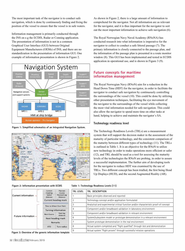
introduction of electronic navigation. The move from an analogue bridge with stand-alone navigation sensors and paper charts, has resulted in a modern bridge with Integrated Navigation Systems (INS) supported by Electronic Navigational Charts (ENCs). The navigation sensors on board is now networked and integrated, facilitating integrated information presentation on Multi-Function Displays (MFDs) as shown in Figure 1.
The sensors and systems within an INS include, but are not limited to (1): 1) The Electronic Position Fixing
System (EPFS), with the use of Global Navigation Satellite Systems (GNSS), providing the absolute position of the vessel (for example Global Positioning System (GPS)).
2) Heading Control System (HCS), providing the heading of the vessel.
3) Speed and Distance Measurement Equipment (SDME), providing the speed of the vessel (and thus distance).
4) Echo sounding system (ESS), providing the depth measurements for the vessel.
5) Navigation support sensors ▪ Wind sensors providing
wind speed and bearing ▪ Optical Bearing Device (OBD)
providing position lines. ▪ Automatic Identification System
(AIS), automatic tracking system used on ships and by vessel traffic services (VTS).
6) Use of Communication channels such as Global Maritime Distress Safety System (GMDSS), which uses for example the NAVTEX to receive navigational messages, or other communication channels for distributing data such as satellite communication (SATCOM) or mobile broadband.
7) Electronic Chart Display and Information System (ECDIS), used for
chart presentation and presentation of relevant information for the navigator.
8) RADAR system, used as a mean for terrestrial positioning.
9) Conning application providing information about the engine and manoeuvring status.
The information is distributed on Local Area Networks (LAN) and presentation of information on MFDs. The aim of the integration of information presentation to the navigator has been to improve the Situation Awareness (SA) for the navigator.
Even though the number of navigation aids have increased in the last decade, the craftsmanship of navigation stays the same. The words of Nathanial Bowditch in the book “The American Practical Navigator” is best suited to explain this:
“Marine navigation blends both science and art. A good navigator constantly thinks strategically, operationally, and tactically. He plans each voyage carefully. As it proceeds, he gathers navigational information from a variety of sources, evaluates this information, and determines his ship’s position… Some important elements of successful navigation cannot be acquired from any book or instructor. The science of navigation can be taught, but the art of navigation must be developed from experience.” (2)
With the introduction of electronic navigation aids for the navigator, the basic craftsmanship of navigation has been challenged in a new way. This has partly come from an over-reliance in the systems providing information to improve the SA of the navigator (3, 4). There are several examples and studies of for example ECDIS-assisted groundings, which are based on an over-reliance in the information being presented on the ECDIS (5).
Coordinates February 2019 | 31
The most important task of the navigator is to conduct safe navigation, which is done by continuously finding and fixing the position of the vessel to ensure that the vessel is in safe waters.
Information management is primarily conducted through the INS on e.g the ECDIS, Radar or Conning application. The presentation of information is not in a common Graphical User Interface (GUI) between Original Equipment Manufacturers (OEMs) of INS, and there are no standardization in the presentation of information GUI. One example of information presentation is shown in Figure 2.
As shown in Figure 2, there is a large amount of information to comprehend for the navigator. Not all information are as relevant for the navigator, and it is thus important for the navigator to sort out the most important information to achieve safe navigation (6).
The Royal Norwegian Navy Naval Academy (RNoNA) has conducted research into what information is imperative for the navigator to collect to conduct a safe littoral passage (7). The primary information is closely connected to the passage plan, and the information of the passage plan is presented in a route monitor window (8). This GUI has been implemented and tested in ECDIS application in operational use, and is shown in Figure 3 (9).
Future concepts for maritime information management
The Royal Norwegian Navy (RNoN) aim for a reduction in the Head Down Time (HDT) for the navigator, in order to facilitate the navigator to conduct safe navigation by continuously controlling the surroundings of the vessel (10). This could be done by utilizing other presentation techniques, facilitating the eye movement of the navigator to the surroundings of the vessel while collecting the most vital information needed for safe navigation. This could also allow the navigator to spend more time on other tasks at hand, helping to achieve and maintain the navigator`s SA.
Technology readiness level
The Technology Readiness Levels (TRLs) are a measurement system that will support the decision maker in the assessment of the maturity of particular technology, and the consistent comparison of the maturity between different types of technology (11). The TRLs is outlined in Table 1. It is an objective for the RNoN to utilize new technology in order to make operations more efficient or safer (12), and TRL should be used as a tool for assessing the maturity levels of the technologies the RNoN are probing, in order to assure a successful implementation. The further aim of developing tools for the navigator to reduce HDT was examined by the use of TRLs. Two different concept has been trialled, the first being Head Up Displays (HUD), and the second Augmented Reality (AR).
TRL LEVEL TRL DESCRIPTION
1 Basic principles observed and reported
2 Technology concept and/or application formulated
3 Analytical and experimental critical function and/or characteristic proof-of concept
4 Component and/or breadboard validation in laboratory environment
5 Component and/or breadboard validation in relevant environment
6 System/subsystem model or prototype demonstration in a relevant environment
7 System prototype demonstration in the real environment
8 Actual system completed and “flight qualified” through test and demonstration
9 Actual system “flight proven” through successful mission operations
Table 1: Technology Readiness Levels (11)Figure 2: Information presentation with ECDIS
Figure 3: Overview of the generic information template
Figure 1: Simplified schematics of an Integrated Navigation System.
32 | Coordinates February 2019
Head Up Display
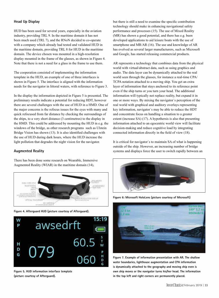
HUD has been used for several years, especially in the aviation industry, providing TRL 9. In the maritime domain it has not been much used (TRL 7), and the RNoN decided to co-operate with a company which already had tested and validated HUD in the maritime domain, providing TRL 8 for HUD in the maritime domain. The device chosen was mounted in a high-resolution display mounted in the frame of the glasses, as shown in Figure 4. Note that there is not a need for a glass in the frame to use them.
The cooperation consisted of implementing the information template in the HUD, an example of one of three interfaces is shown in Figure 5. The interface is aligned with the information needs for the navigator in littoral waters, with reference to Figure 3.
In the display the information depicted in Figure 5 is presented. The preliminary results indicate a potential for reducing HDT, however there are several challenges with the use of HUD in a HMD. One of the major concerns is the refocus issues for the eyes with many and quick refocused from far distance by checking the surroundings of the ships, to a very short distance (3 centimetres) to the display in the HMD. This could be addressed by mounting the HUD in e.g. the windows of the bridge, as other research programs such as Ulstein Bridge Vision has shown (13). It is also identified challenges with the use of HUD during dark hours, where the HUD increase the light pollution that degrades the night vision for the navigator.
Augmented Reality
There has been done some research on Wearable, Immersive Augmented Reality (WIAR) in the maritime domain (14),
but there is still a need to examine the specific contribution technology should make in enhancing navigational safety performance and processes (15). The use of Mixed Reality (MR) has shown a good potential, and there has e.g. been developed applications to aid leisure boats with the use of smartphone and MR/AR (16). The use and knowledge of AR has evolved as several larger manufacturers, such as Microsoft and Google, has started releasing commercial products.
AR represents a technology that combines data from the physical world with virtual/abstract data, such as using graphics and audio. The data layer can be dynamically attached to the real world seen through the glasses, for instance a real-time CPA/TCPA notation attached to a moving ship. You get an extra layer of information that stays anchored to its reference point even if the ship turns or you turn your head. The additional information will typically not replace reality, but expand it in one or more ways. By mixing the navigator`s perception of the real world with graphical and auditory overlays representing key information, navigator`s may be able to reduce the HDT and concentrate focus on handling a situation to a greater extent (increase SA) (17). A hypothersis is also that presenting information attached to an egocentric world view will facilitate decision-making and reduce cognitive load by integrating connected information directly in the field of view (18).
It is critical for navigator`s to maintain SA of what is happening outside of the ship. However, an increasing number of bridge systems and displays force the user to switch rapidly between an
Figure 4. Afterguard HUD (picture courtesy of Afterguard).
Figure 5. HUD information interface template (picture courtesy of Afterguard).
Figure 6: Microsoft HoloLens (picture courtesy of Microsoft)
Figure 7. Example of information presentation with AR. The shallow water boundaries, lighthouse augmentation and CPA information is dynamically attached to the geography and moving ship even is own ship moves or the navigator turns his/her head. The information in the top left and right corners are permanently placed.
Coordinates February 2019 | 33
outside view and the screens inside. AR technologies could help solve these issues by overlaying the physical world with digital content such as graphics and possibly aiding with audio. Designing AR systems is a new and complex design space as it requires an extensive understanding of the users’ context, and in addition how the technology applies to that context. The understanding of the real-world implications of rapidly shifting contextual factors is essential for designing systems that support operators’ SA (17).
In the Maritime Augmented Reality (M-AR) project, the RNoN cooperates with other partners to investigate the use of AR technology in an operational maritime environment. The aim is to enhance the navigator`s SA by reducing HDT by providing the navigator with augmented information where it is needed. The information template in Figure 3 is used as a baseline, but at the same time AR can provide augmented information regarding the surroundings of the vessel. It is important to note that this information should not only be the reproduction of existing system symbology the augmented way (14). The M-AR project use the Microsoft HoloLens (Figure 6), which has TRL 8 in the gaming domain (19). In the maritime domain, the HoloLens has TRL level 6. The aim of the product is to increase the TRL to level 7 by demonstrating the use of it in an operational environment.
The project is still in an early phase, and a first version is planned late 2018. The content of the information presentation could be as shown in Figure 7.
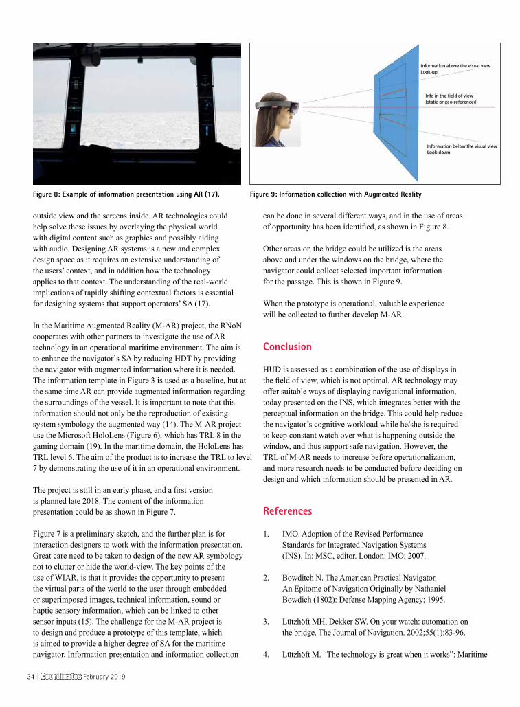
Figure 7 is a preliminary sketch, and the further plan is for interaction designers to work with the information presentation. Great care need to be taken to design of the new AR symbology not to clutter or hide the world-view. The key points of the use of WIAR, is that it provides the opportunity to present the virtual parts of the world to the user through embedded or superimposed images, technical information, sound or haptic sensory information, which can be linked to other sensor inputs (15). The challenge for the M-AR project is to design and produce a prototype of this template, which is aimed to provide a higher degree of SA for the maritime navigator. Information presentation and information collection
can be done in several different ways, and in the use of areas of opportunity has been identified, as shown in Figure 8.
Other areas on the bridge could be utilized is the areas above and under the windows on the bridge, where the navigator could collect selected important information for the passage. This is shown in Figure 9.
When the prototype is operational, valuable experience will be collected to further develop M-AR.
Conclusion
HUD is assessed as a combination of the use of displays in the field of view, which is not optimal. AR technology may offer suitable ways of displaying navigational information, today presented on the INS, which integrates better with the perceptual information on the bridge. This could help reduce the navigator’s cognitive workload while he/she is required to keep constant watch over what is happening outside the window, and thus support safe navigation. However, the TRL of M-AR needs to increase before operationalization, and more research needs to be conducted before deciding on design and which information should be presented in AR.
References
1. IMO. Adoption of the Revised Performance Standards for Integrated Navigation Systems (INS). In: MSC, editor. London: IMO; 2007.
2. Bowditch N. The American Practical Navigator. An Epitome of Navigation Originally by Nathaniel Bowdich (1802): Defense Mapping Agency; 1995.
3. Lützhöft MH, Dekker SW. On your watch: automation on the bridge. The Journal of Navigation. 2002;55(1):83-96.
4. Lützhöft M. “The technology is great when it works”: Maritime
Figure 8: Example of information presentation using AR (17). Figure 9: Information collection with Augmented Reality
34 | Coordinates February 2019
Technology and Human Integration on the Ship’s Bridge: Linköping University Electronic Press; 2004.
5. MAIB. Ecdis-assisted grounding MARS Report 200930. London: Marine Accident Investigation Branch; 2008.
6. Porathe T. Ship navigation-Information integration in the maritime domain. Information Design: Research and Practice. 2017.
7. Hareide OS, Mjelde FV, Glomsvoll O, Ostnes R, editors. Developing a High-Speed Craft Route Monitor Window. International Conference on Augmented Cognition; 2017: Springer.
8. Hareide OS, Ostnes R. Scan Pattern for the Maritime Navigator. Transnav. 2017;11(1):39-47.
9. Hareide OS, Ostnes R, editors. Validation of a Maritime Usability Study with Eye Tracking
Data2018; Cham: Springer International Publishing.
10. Hareide OS. Improving Passage Information Management for the Modern Navigator. In: IALA, editor. 19th IALA Conference 2018; Incheon, South-Korea: IALA; 2018.
11. Mankins JC. Technology readiness levels. White Paper, April. 1995;6.
12. Sjøforsvarsstaben. Sjøforsvarets Strategiske Konsept, 2016-2040. Bergen2014.
13. Ulstein. Ulstein Bridge Vision ulstein.com2016 [Available from: https://ulstein.com/innovations/bridge-vision.
14. Procee S, Borst C, van Paassen M, Mulder M, Bertram V. Toward Functional Augmented Reality in Marine Navigation: A Cognitive Work Analysis. 2017.
15. Grabowski M. Research on
wearable, immersive augmented reality (wiar) adoption in maritime navigation. The Journal of Navigation. 2015;68(3):453-64.
16. Porathe T, Ekskog J. Egocentric Leisure Boat Navigation in a Smartphone-based Augmented Reality Application. The Journal of Navigation. 2018:1-13.
17. Frydenberg S, Nordby K, Eikenes J. Exploring designs of augmented reality systems for ship bridges in arctic waters. Human Factors. 2018;26:27.
18. Porathe T. 3-D nautical charts and safe navigation: Institutionen för Innovation, Design och Produktutveckling; 2006.
19. Von Itzstein GS, Billinghurst M, Smith RT, Thomas BH. Augmented Reality Entertainment: Taking Gaming Out of the Box. Encyclopedia of Computer Graphics and Games: Springer; 2017. p. 1-9.
GI DATA
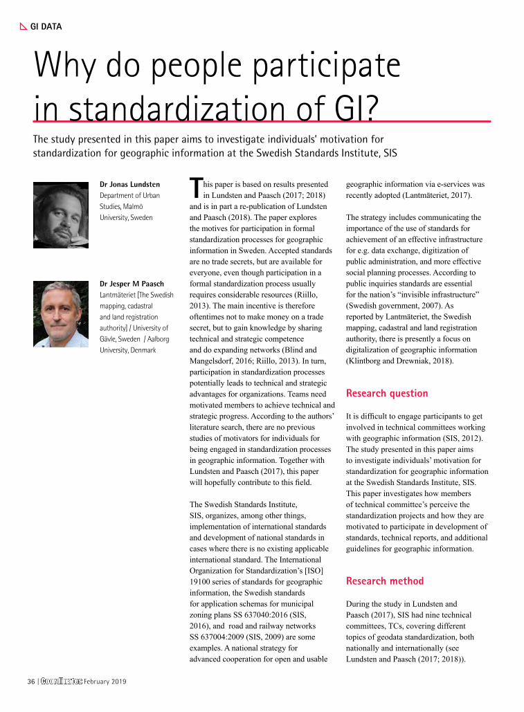
Why do people participate in standardization of GI?The study presented in this paper aims to investigate individuals’ motivation for standardization for geographic information at the Swedish Standards Institute, SIS
Dr Jonas LundstenDepartment of Urban Studies, Malmö University, Sweden
Dr Jesper M PaaschLantmäteriet [The Swedish mapping, cadastral and land registration authority] / University of Gävle, Sweden / Aalborg University, Denmark
This paper is based on results presented in Lundsten and Paasch (2017; 2018)
and is in part a re-publication of Lundsten and Paasch (2018). The paper explores the motives for participation in formal standardization processes for geographic information in Sweden. Accepted standards are no trade secrets, but are available for everyone, even though participation in a formal standardization process usually requires considerable resources (Riillo, 2013). The main incentive is therefore oftentimes not to make money on a trade secret, but to gain knowledge by sharing technical and strategic competence and do expanding networks (Blind and Mangelsdorf, 2016; Riillo, 2013). In turn, participation in standardization processes potentially leads to technical and strategic advantages for organizations. Teams need motivated members to achieve technical and strategic progress. According to the authors’ literature search, there are no previous studies of motivators for individuals for being engaged in standardization processes in geographic information. Together with Lundsten and Paasch (2017), this paper will hopefully contribute to this field.
The Swedish Standards Institute, SIS, organizes, among other things, implementation of international standards and development of national standards in cases where there is no existing applicable international standard. The International Organization for Standardization’s [ISO] 19100 series of standards for geographic information, the Swedish standards for application schemas for municipal zoning plans SS 637040:2016 (SIS, 2016), and road and railway networks SS 637004:2009 (SIS, 2009) are some examples. A national strategy for advanced cooperation for open and usable
geographic information via e-services was recently adopted (Lantmäteriet, 2017).
The strategy includes communicating the importance of the use of standards for achievement of an effective infrastructure for e.g. data exchange, digitization of public administration, and more effective social planning processes. According to public inquiries standards are essential for the nation’s “invisible infrastructure” (Swedish government, 2007). As reported by Lantmäteriet, the Swedish mapping, cadastral and land registration authority, there is presently a focus on digitalization of geographic information (Klintborg and Drewniak, 2018).
Research question
It is difficult to engage participants to get involved in technical committees working with geographic information (SIS, 2012). The study presented in this paper aims to investigate individuals’ motivation for standardization for geographic information at the Swedish Standards Institute, SIS. This paper investigates how members of technical committee’s perceive the standardization projects and how they are motivated to participate in development of standards, technical reports, and additional guidelines for geographic information.
Research method
During the study in Lundsten and Paasch (2017), SIS had nine technical committees, TCs, covering different topics of geodata standardization, both nationally and internationally (see Lundsten and Paasch (2017; 2018)).
36 | Coordinates February 2019
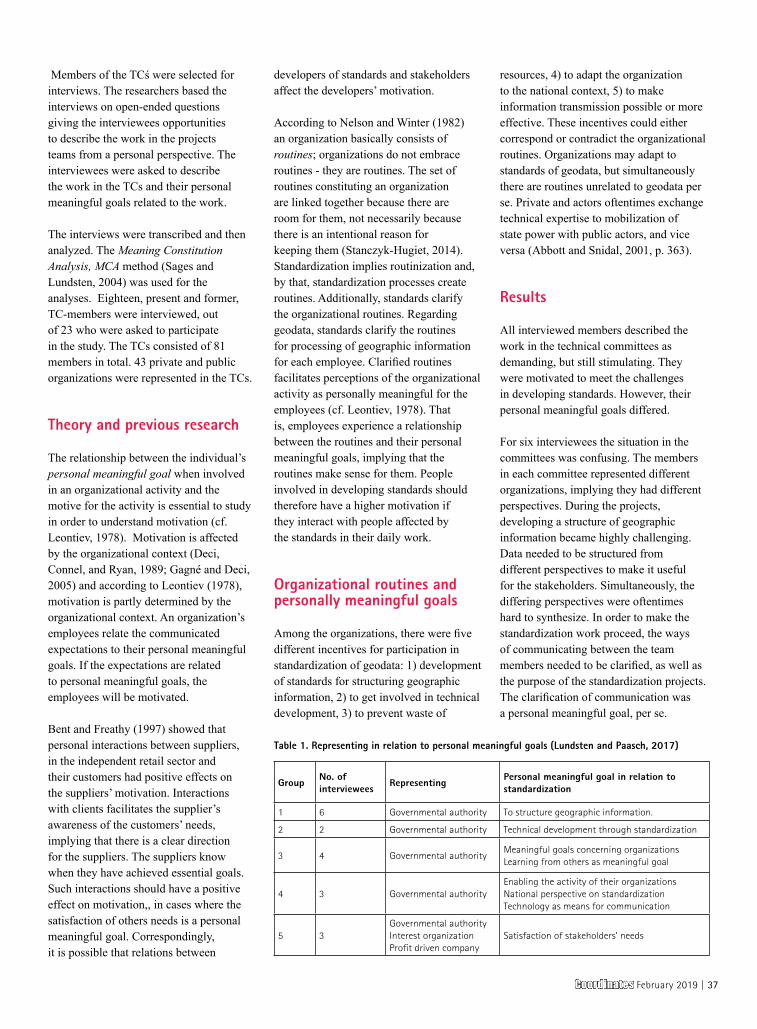
Members of the TCś were selected for interviews. The researchers based the interviews on open-ended questions giving the interviewees opportunities to describe the work in the projects teams from a personal perspective. The interviewees were asked to describe the work in the TCs and their personal meaningful goals related to the work.
The interviews were transcribed and then analyzed. The Meaning Constitution Analysis, MCA method (Sages and Lundsten, 2004) was used for the analyses. Eighteen, present and former, TC-members were interviewed, out of 23 who were asked to participate in the study. The TCs consisted of 81 members in total. 43 private and public organizations were represented in the TCs.
Theory and previous research
The relationship between the individual’s personal meaningful goal when involved in an organizational activity and the motive for the activity is essential to study in order to understand motivation (cf. Leontiev, 1978). Motivation is affected by the organizational context (Deci, Connel, and Ryan, 1989; Gagné and Deci, 2005) and according to Leontiev (1978), motivation is partly determined by the organizational context. An organization’s employees relate the communicated expectations to their personal meaningful goals. If the expectations are related to personal meaningful goals, the employees will be motivated.
Bent and Freathy (1997) showed that personal interactions between suppliers, in the independent retail sector and their customers had positive effects on the suppliers’ motivation. Interactions with clients facilitates the supplier’s awareness of the customers’ needs, implying that there is a clear direction for the suppliers. The suppliers know when they have achieved essential goals. Such interactions should have a positive effect on motivation,, in cases where the satisfaction of others needs is a personal meaningful goal. Correspondingly, it is possible that relations between
developers of standards and stakeholders affect the developers’ motivation.
According to Nelson and Winter (1982) an organization basically consists of routines; organizations do not embrace routines - they are routines. The set of routines constituting an organization are linked together because there are room for them, not necessarily because there is an intentional reason for keeping them (Stanczyk-Hugiet, 2014). Standardization implies routinization and, by that, standardization processes create routines. Additionally, standards clarify the organizational routines. Regarding geodata, standards clarify the routines for processing of geographic information for each employee. Clarified routines facilitates perceptions of the organizational activity as personally meaningful for the employees (cf. Leontiev, 1978). That is, employees experience a relationship between the routines and their personal meaningful goals, implying that the routines make sense for them. People involved in developing standards should therefore have a higher motivation if they interact with people affected by the standards in their daily work.
Organizational routines and personally meaningful goals
Among the organizations, there were five different incentives for participation in standardization of geodata: 1) development of standards for structuring geographic information, 2) to get involved in technical development, 3) to prevent waste of
resources, 4) to adapt the organization to the national context, 5) to make information transmission possible or more effective. These incentives could either correspond or contradict the organizational routines. Organizations may adapt to standards of geodata, but simultaneously there are routines unrelated to geodata per se. Private and actors oftentimes exchange technical expertise to mobilization of state power with public actors, and vice versa (Abbott and Snidal, 2001, p. 363).
Results
All interviewed members described the work in the technical committees as demanding, but still stimulating. They were motivated to meet the challenges in developing standards. However, their personal meaningful goals differed.
For six interviewees the situation in the committees was confusing. The members in each committee represented different organizations, implying they had different perspectives. During the projects, developing a structure of geographic information became highly challenging. Data needed to be structured from different perspectives to make it useful for the stakeholders. Simultaneously, the differing perspectives were oftentimes hard to synthesize. In order to make the standardization work proceed, the ways of communicating between the team members needed to be clarified, as well as the purpose of the standardization projects. The clarification of communication was a personal meaningful goal, per se.
Group No. of interviewees
Representing Personal meaningful goal in relation to standardization
1 6 Governmental authority To structure geographic information.
2 2 Governmental authority Technical development through standardization
3 4 Governmental authorityMeaningful goals concerning organizationsLearning from others as meaningful goal
4 3 Governmental authorityEnabling the activity of their organizationsNational perspective on standardizationTechnology as means for communication
5 3Governmental authorityInterest organizationProfit driven company
Satisfaction of stakeholders’ needs
Table 1. Representing in relation to personal meaningful goals (Lundsten and Paasch, 2017)
Coordinates February 2019 | 37
For two interviewees the main focus was on the technical aspects of standardization. The technical development, emerging from the standardization projects, should benefit the community in general. The opportunity to contribute to technical development was a personal meaningful goal for these interviewees.
Four interviewees experienced that their organizations did not prioritize the standardization projects. Consequently, they had to minimize their time spent on standardization projects. In order to contribute in the Technical committees they had to be efficient and minimize waste of time and additional resources. Their personal meaningful goals differed, but all of them concerned the interests of their organizations, for instance, knowledge development beneficial for the organization.
Three employees expressed that the standardization projects were valuable for development of guidelines for standardization of national geographic data. For these interviewees development of means for information transmission was the main personal meaningful goal.For three interviewees the standardization work implied frequent interactions with stakeholders. Their personal meaningful goals were related to satisfaction of their stakeholders’ needs. These three interviewees differed from the remaining interviewees in one critical aspect, namely the other interviewees mainly represented governmental organizations, whereas the three interviewees represented an interest organization and a profit driven company. Interviewees from group 1–4 share two common features. They represent a governmental authority and their personal meaningful goals were not directly related to the stakeholders. Interviewees from group 5 represented a governmental authority, interest organization, and a profit driven company. Their personal meaningful goals were directly related to stakeholders.
Analysis and discussion
The results presented in Lundsten and Paasch (2017; 2018) showed that a
major motive for organizations and individuals to participate in formal standardization is to contribute to the development of standards for the description and exchange of geographic information. Interviewees which had frequent interactions with stakeholders experienced the standardization project as a personal meaningful goal. This finding i in line with research implying that personal interactions with clients facilitate motivation (cf. Bent and Freathy, 1997).
Interviewees whos personal meaningful goal was to satisfy stakeholders’ needs represented organizations with routines implying frequent interactions with stakeholders. There were contradictions between the aims of the standardization processes, the personal meaningful goals, and the organizational routines, for interviewees representing organizations with routines implying no frequent interactions with stakeholders. These interviewees said that they could not make a proper contribution due to other priorities in the participant’s organization outside one’s own control. For some of these interviewees a personal goal was to learn from other commission members.
This observation seems to contradict the views expressed in e.g. the Swedish national geodata strategy that standards are an important part of the geographic information infrastructure and the effort of financing access for users to standards. There is a generally wish among the stakeholders that it is important that standards are being used.
Participation in the formal standardization process is voluntary and in line with the Swedish principles of governmental autonomy. Swedish governmental agencies therefore hold a considerable high level of autonomy due to a century’s old and constitutionally enshrined principle and are independently managed under performance management by the government (Hall, Nilsson and Löfgren, 2011). This autonomy means that agencies to a large extent can make their own decisions concerning if, and how they want to be participate in national and international standardization (Swedish government, 2007, p. 123).
Conclusion
The study presented here was published in Lundsten and Paasch (2017) and investigated individual motives for participation in formal standardization of geographic information. Personal interviews were conducted with chairmen and members of Technical Committees at the Swedish Standards Institute.
The majority of the interviewees expressed a strong personal motivation in standardization of geographic data and only a minority expressed lack of motivation for participating in standardization projects per se. The interviewees’ motivation corresponded to the interest of their organizations. It is however not sufficient for the participating organizations just to support the financial obligations of being part of a technical committee by paying participation fees, etc. If the individual participants´ time is not allocated for the specific purpose to participate in the technical committee it may lead to lack of motivation and poor working conditions. This is due to the feeling of not being able to participate in an optimal way and that the work is regarded as less important than other work activities closer to the routines in the employees’ organization. This view has even been expressed by some of the interviewees.
The study showed that interviewees representing organizations with frequent stakeholders’ contacts described the standardization as personally meaningful for themselves as individuals. The stakeholders’ needs were related to the standardization projects and the interactions with stakeholders made the purpose of standardization clear.
References
Abbott, K.W., and Snidal, D. (2001). International “standards” and international governance. Journal of European Public Policy, 8(3), pp. 345-370.
Bent, R., and Freathy, P. (1997). Motivating the employee in the independent retail sector. Journal of Retailing and Consumer Services, 4(3), pp. 201–208.
38 | Coordinates February 2019
Blind, K., and Mangelsdorf, A. (2016). Motives to standardize: Empirical evidence from Germany. Technovation, 48–49, pp. 13–24.
Deci, E. L., Connel, J. P., and Ryan, R. M. (1989). Self-determination in a work organization. Journal of Applied Psychology, 74(4), pp. 580-590.
Gagné, M. and Deci, E.L. (2005). Self determination theory and work motivation. Journal of organizational behavior, 26, pp. 331-362.
Hall, P., Nilsson, T., and Löfgren, K. (2011). Bureaucratic autonomy revisited: Informal aspects of agency autonomy in Sweden. Paper presented at the Permanent Study Group VI on Governance of Public Sector organizations, Annual Conference of EGPA. Bucharest, Romania.
Klintborg, M. and Drewniak, M. (2018). Digitalt Först- För en smartare samhällsbyggnadsprocess [Digital First - For a smarter Planning and Community Development Process.] (In Swedish). Report 2018:1. Gävle, Sweden: Lantmäteriet [The Swedish mapping, cadastral and land registration authority].
Lantmäteriet (2017). The National Geodata Strategy 2016-2020. Report no. 2017:1.
Gävle, Sweden: Lantmäteriet [The Swedish mapping, cadastral and land registration authority].
Leontiev, A. N. (1978). Activity, consciousness, and personality. Englewood Cliffs, NJ: Prentice-Hall.
Lundsten, J. and Paasch, J.M. (2017). Motives for Participation in Formal Standardization Processes for Geographic Information - An Empirical Study in Sweden. In International Journal of Standardization Research. 15(1), pp.16-28.
Lundsten J. and Paasch, J.M. (2018). Individual’s motivation in standardization of geographic information. In Proceedings of FIG Conference 2018. Istanbul, Turkey, 6-11 May. International Federation of Surveyors (FIG), Copenhagen, Denmark. ID 9364.
Nelson R. R., and Winter S. G. (1982), An Evolutionary Theory of Economic
Change, Belknap Press, Cambridge.
Riillo, C. (2013). Profiles and motivations of Standardization Players. International Journal of IT Standards and Standardization Research, 11(2), pp. 17-33.
Sages, R., and Lundsten, J. (2004). The ambiguous nature of psychology as science and its bearing on methods of inquiry. In M. Lahlou, and R. B. Sages (Eds.), Mèthodes et Terrains de la Psychologie Interculturelle (pp. 189-220). Lyon, France: L´Interdisciplinaire, Limonest.
Spinuzzi, C. (2011). Losing by expanding: Coralling the runaway object. Journal of Business and Technical Communication, 25(4), pp. 449–486.
Swedish government (2007). Den osynliga infrastrukturen - om förbättrad samordning av offentlig IT-standardisering. SOU 2007:47 [The invisible infrastructure - concerning improved coordination of public IT-standardization. SOU 2007:47]. Stockholm, Sweden: Ministry of Enterprise and Innovation.
SIS (2009). SS 637004:2009. Geografisk information - Väg- och järnvägsnät - Applikationsschema [Geographic information - Road and railway networks - Application schema]. Stockholm, Sweden: Swedish Standards Institute,SIS.
SIS (2012). Rapport om förslag till utveckling av Stanlis metodik. [Report on suggestions for development of the STANLI methodology] (In swedish). 2012-05-25. Stockholm, Sweden: Swedish Standards Institute, SIS, Technical committee TK323.
SIS (2016). SS 637040:2016. Geografisk information - Detaljplan - Applikationsschema för planbestämmelser [Geographic information - Detail plan- Application schema for planning instructions]. Stockholm, Sweden: Swedish Standards Institute.
Stanczyk-Hugiet, E. (2014). Routines in the process of organizational evolution. Management, 18, (2), pp. 73-87.
NEWS - UAV
Use of civilian drones in Germany
A study by the German Aerospace Center (Deutsches Zentrum für Luft- und Raumfahrt; DLR) has now revealed that there is clear approval in Germany for the use of civilian drones in civil protection, rescue missions and research work. However, flights for advertising, leisure and parcel delivery purposes are still viewed negatively by at least half of those questioned. .
“Regardless of gender or age, the term ‘drone’ is known to almost everyone, but often retains negative connotations,” explains study leader Maria Stolz of the DLR Institute of Flight Guidance in Braunschweig. “Experience with drones remains rare and is more usually passive, rather than active. There is still relatively little information available to the public on this topic.” Only around 40 percent of those surveyed said that they had ever seen or heard a drone, while just 10 percent had ever flown a drone themselves. The attitude towards civilian drones depends on gender and age, among other factors. Those expressing an interest in this modern technology were predominantly young males. “We were also interested to see whether the respondents changed their attitude over the course of the interview,” says Stolz. “There was a slight shift towards a more positive view.
The researchers were able to establish that there is currently clear approval for the use of drones in civil protection, rescue missions and research work. Around two-thirds of respondents agreed fully or partially with the use of drones in order to ascertain the situation in often inaccessible disaster areas, or to support the police and fire brigade in life-saving missions by providing situational information or location data. www.dlr.de
UAV can help avocado growers by detecting asymptomatic pathogen
Remote imaging can effectively detect a pathogen that endangers the $100 million-a-year Florida avocado industry – even before the trees show symptoms Yiannis Ampatzidis, an assistant professor of
Coordinates February 2019 | 39
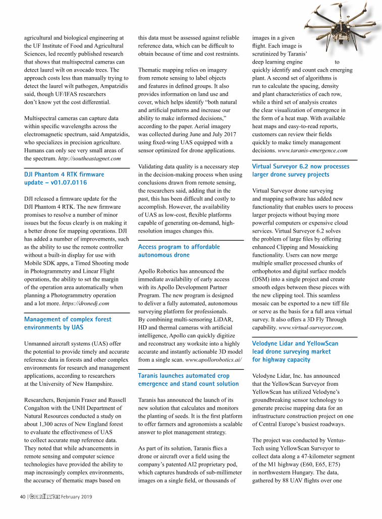
this data must be assessed against reliable reference data, which can be difficult to obtain because of time and cost restraints.
Thematic mapping relies on imagery from remote sensing to label objects and features in defined groups. It also provides information on land use and cover, which helps identify “both natural and artificial patterns and increase our ability to make informed decisions,” according to the paper. Aerial imagery was collected during June and July 2017 using fixed-wing UAS equipped with a sensor optimized for drone applications.
Validating data quality is a necessary step in the decision-making process when using conclusions drawn from remote sensing, the researchers said, adding that in the past, this has been difficult and costly to accomplish. However, the availability of UAS as low-cost, flexible platforms capable of generating on-demand, high-resolution images changes this.
Access program to affordable autonomous drone
Apollo Robotics has announced the immediate availability of early access with its Apollo Development Partner Program. The new program is designed to deliver a fully automated, autonomous surveying platform for professionals. By combining multi-sensoring LiDAR, HD and thermal cameras with artificial intelligence, Apollo can quickly digitize and reconstruct any worksite into a highly accurate and instantly actionable 3D model from a single scan. www.apollorobotics.ai/
Taranis launches automated crop emergence and stand count solution
Taranis has announced the launch of its new solution that calculates and monitors the planting of seeds. It is the first platform to offer farmers and agronomists a scalable answer to plot management strategy.
As part of its solution, Taranis flies a drone or aircraft over a field using the company’s patented AI2 proprietary pod, which captures hundreds of sub-millimeter images on a single field, or thousands of
images in a given flight. Each image is scrutinized by Taranis’ deep learning engine to quickly identify and count each emerging plant. A second set of algorithms is run to calculate the spacing, density and plant characteristics of each row, while a third set of analysis creates the clear visualization of emergence in the form of a heat map. With available heat maps and easy-to-read reports, customers can review their fields quickly to make timely management decisions. www.taranis-emergence.com
Virtual Surveyor 6.2 now processes larger drone survey projects
Virtual Surveyor drone surveying and mapping software has added new functionality that enables users to process larger projects without buying more powerful computers or expensive cloud services. Virtual Surveyor 6.2 solves the problem of large files by offering enhanced Clipping and Mosaicking functionality. Users can now merge multiple smaller processed chunks of orthophotos and digital surface models (DSM) into a single project and create smooth edges between these pieces with the new clipping tool. This seamless mosaic can be exported to a new tiff file or serve as the basis for a full area virtual survey. It also offers a 3D Fly Through capability. www.virtual-surveyor.com.
Velodyne Lidar and YellowScan lead drone surveying market for highway capacity
Velodyne Lidar, Inc. has announced that the YellowScan Surveyor from YellowScan has utilized Velodyne’s groundbreaking sensor technology to generate precise mapping data for an infrastructure construction project on one of Central Europe’s busiest roadways.
The project was conducted by Ventus-Tech using YellowScan Surveyor to collect data along a 47-kilometer segment of the M1 highway (E60, E65, E75) in northwestern Hungary. The data, gathered by 88 UAV flights over one
agricultural and biological engineering at the UF Institute of Food and Agricultural Sciences, led recently published research that shows that multispectral cameras can detect laurel wilt on avocado trees. The approach costs less than manually trying to detect the laurel wilt pathogen, Ampatzidis said, though UF/IFAS researchers don’t know yet the cost differential.
Multispectral cameras can capture data within specific wavelengths across the electromagnetic spectrum, said Ampatzidis, who specializes in precision agriculture. Humans can only see very small areas of the spectrum. http://southeastagnet.com
DJI Phantom 4 RTK firmware update – v01.07.0116
DJI released a firmware update for the DJI Phantom 4 RTK. The new firmware promises to resolve a number of minor issues but the focus clearly is on making it a better drone for mapping operations. DJI has added a number of improvements, such as the ability to use the remote controller without a built-in display for use with Mobile SDK apps, a Timed Shooting mode in Photogrammetry and Linear Flight operations, the ability to set the margin of the operation area automatically when planning a Photogrammetry operation and a lot more. https://dronedj.com
Management of complex forest environments by UAS
Unmanned aircraft systems (UAS) offer the potential to provide timely and accurate reference data in forests and other complex environments for research and management applications, according to researchers at the University of New Hampshire.
Researchers, Benjamin Fraser and Russell Congalton with the UNH Department of Natural Resources conducted a study on about 1,300 acres of New England forest to evaluate the effectiveness of UAS to collect accurate map reference data. They noted that while advancements in remote sensing and computer science technologies have provided the ability to map increasingly complex environments, the accuracy of thematic maps based on
40 | Coordinates February 2019

month, enabled engineers to design a plan to expand the highway from 2+2 lanes to 3+3 lanes. YellowScan Surveyor includes Velodyne Lidar’s Puck™, a compact and versatile sensor that delivers a high-resolution surround view image to accurately measure and analyze any landscape. [email protected]
China’s SZMID highlights handheld C-UAV systemSource: SZMID
Shen Zhou Ming Da High Technology Co Ltd (SZMID), a Beijing-based company specialising in radio frequency (RF) detection and jamming technology for counter unmanned aerial vehicle (C-UAV) applications, is eyeing export opportunities for its indigenously developed DZ-02 Pro Portable Jammer Gun.
The DZ-02 Pro is intended to counter commercial multirotor and small fixed-wing UAVs, and can disrupt satellite navigation signals - BeiDou Galileo, GLONASS, and GPS systems - as well as RF communications in the 1.56 Mhz-1.62 GHz, 2.4-2.483 GHz, and 5.725-5.85 GHz wavelengths up to a maximum range of 1 km. It is designed to cause a target to hover in place until its power is depleted or activate its return-home protocol. www.janes.com
New York Power Authority investigates LiDAR with drones
The New York Power Authority (NYPA) has received funding to research and integrate LiDAR technology into its existing UAS program for vegetation management inspections along its transmission lines.
In February, NYPA will begin a yearlong pilot project to determine the optimal combination of drone and LiDAR technology for use in utility industry inspections. NYPA’s research and development team will evaluate combinations of drone and LiDAR technology, aimed at keeping the total weight of a drone with LiDAR equipment under 55 pounds in order to comply with the Federal Aviation Administration’s Part 107 regulations
RIEGL LMS GmbH, Austria | RIEGL USA Inc. | RIEGL Japan Ltd. | RIEGL China Ltd.
Key Features:
| echo digitization & online waveform processing | multiple target capability | eyesafe laser class 1| ideally suited for the implementation of emerging surveying solutions by UAS/UAV/RPAS | mechanical and electrical interface for IMU mounting
Very Compact & Lightweight
1.55 kg / 3.4 lbs • max. operating
flight altitude 330 ft AGL • range up to 250 m • accuracy 15 mm,
precision 10 mm • well suited for
measuring snow and ice terrains
Compact & Lightweight 3.5 kg / 7.7 lbs
• max. operating flight altitude 1,150 ft AGL
• range up to 920 m • accuracy 10 mm, precision 5 mm
• ideally suited for power line, railway track, and pipeline inspection
ULS
RIEGL VUX-240 UAV Laser Scanner • for use on UAS/UAV/RPAS and small manned aeroplanes and helicopters
• Laser PRR up to 1.8 MHz, wide FOV of 75°
1.55 kg 3.4 lbs
3.5 kg 7.7 lbs
RIEGL miniVUX-1UAV
RIEGL VUX-1UAV
up to 360° Field of View
FOV330°
NEW
www.riegl.com
newsroom.riegl.international
up to 330° Field of View
Survey-grade LiDAR performance with a size, weight, and cost factor that makes deployment on sUAVs practical and economical for commercial applications!
RIEGL'S UAV LiDAR SENSORSFor Professional UAV Surveying Missions!
NEWS - IMAGING
Hidden Irish archaeological sites revealed by Bluesky
The National Monuments Service in Ireland is using high-resolution aerial photography from Bluesky to map and investigate a giant 4,500-year-old Henge. The circular structure, located the Brú na Bóinne UNESCO World Heritage Site, is evidence of prehistoric earthworks and was first observed by researchers with drones. Following the discovery, the National Monument Service of the Department of Culture, Heritage, and Gaeltacht carried out extensive aerial reconnaissance including commissioning Bluesky Ireland to survey the cropmark enclosure at Newgrange.
In the summer of 2018 researcher and photographer Anthony Murphy decided to fly his drone over the Boyne Valley and located a large, circular crop mark in open farmland, indicating the presence of buried archaeological features.
Following the initial discovery the NMS used a GIS to organize views of the landscape across maps, photographs, and drawings of cropmarks identified to date. The location of the newly identified site was also visited to enable a better understanding of the topographical locations and the physical and visual relationships between sites.
Chinese scientists capture nighttime remote sensing imagery
Chinese scientists have released nighttime remote sensing imagery capturing finer spatial details of artificial nighttime light in China.
The imagery is made up of 275 photos taken from June to December in 2018 across China. It is made by Wuhan University and Hubei high-resolution earth observation statistics and application center in central China’s Hubei Province.
The details of artificial light captured on the imagery can reveal human activities at night. Activities including oil or natural gas burning, forest fires and volcano eruptions are also captured. www.xinhuanet.com
for the operation of small UAS. NYPA expects the drone operations to reduce the inspection cycle through improved responsiveness and shorter inspection times and greatly reduce hazards by eliminating the need to place contractors or employees near energized equipment.
FLIR Systems acquires Aeryon Labs for $200m
FLIR Systems, Inc. has recently announced acquisition of Aeryon Labs Inc., a leading developer of high-performance unmanned aerial systems (UAS) for the global military, public safety, and critical infrastructure markets for $200 million. www.flir.com
ConnexiCore and Telarus partnership
ConnexiCore has announced a partnership with Telarus, the largest privately held Technology Services Distributor in the United States, that ultimately positions ConnexiCore’s Drone Flight Services and Solutions through the Telarus agent channel. For Telarus, the partnership positions the company into the Drone/UAS aerial intelligence marketplace. www.connexicore.com
Airobotics adds lidar into aerial drones
Airobotics has announced introducing lidar capabilities into its commercial aerial drones to provide additional applications for industries such as mining, construction, and industrial infrastructure. Until a few years ago, adding lidar functions to aerial drones was complicated, since the sensors were hefty and required manual data processing. .”
Microdrones acquires Aircam UAV Technology
Microdrones has acquired Aircam UAV Technology (“Aircam”), a 64 employee Chinese company with its main location in Foshan, in China. Aircam has developed a large Chinese and Southeast Asian customer base with a focus on surveying & mapping, utilities, and oil & gas industries. microdrones.com
Testing vehicular emission using RS in Delhi, India
Trials of checking vehicular emission by remote sensing have started in Delhi and around, a move which experts said could allow efficient screening of highly polluting vehicles.
The technology is being tested at the Manesar-based International Centre for Automotive Technology (ICAT). At least 70,000 vehicles in Delhi and NCR towns have already been checked, the Supreme Court-appointed body Environment Pollution (Prevention and Control) Authority was informed.
A senior official from ICAT explained that in remote sensing there is a light source and a detector that is placed on the side of the road. It transmits a laser beam. Emissions are measured when vehicles cross the light path. Scientists have been able to measure exhaust plume, nitric oxide, carbon monoxide, hydrocarbons and carbon monoxide in 0.5 seconds. Several vehicles can be tested in an hour by the use of this technology, the official said. www.hindustantimes.com
New group of Earth remote sensing satellites “Sovereign’s Eye”
Russian state space corporation Roscosmos has suggested to create a group of Earth remote sensing satellites called “Sovereign’s Eye,” Roscosmos’s head Dmitry Rogozin told reporters.
This group of satellites may be found helpful by the Russian Emergencies Ministry and agricultural workers. “For instance, for the Russian Emergencies Ministry, we will be able to deploy firefighting aircraft to an area of 25 sq m. We will also present the project to argicultural workers. This will include using drones in agriculture and the possibility of monitoring arable land,” Rogozin noted.
The “Sovereign’s Eye” system will also help monitor changes in infrastructure facilities, the Roscosmos head noted. http://tass.com
42 | Coordinates February 2019
Satellite launched By ISRO, made by students, is lighter than a chair
The world’s lightest satellite, made by Indian students, was successfully placed in orbit by a rocket launched by the ISRO on 24th Jan 2019. It’s on the house - not a single rupee is being charged by the Indian Space Research Organisation (ISRO) for the task. The satellite designed and built by students who work with a private organisation called “Space Kidz India” in Chennai weighs less than a wooden chair at only 1.26 kg.
It cost Rs.12 lakh to make and was made ready in six days, though the group perfected the technology over a span of six years, said Srimathy Kesan, a 45-year-old professional who steered this motley group of 20-something at Space Kidz India.
The Kalamsat-V2 is the lightest satellite in the world, the ISRO said, adding that the launch from the Satish Dhawan Space Centre in Sriharikota also marks another milestone - it’s the first satellite designed and built by an Indian private entity and Space Kidz India to be launched by ISRO.
Vietnam’s MicroDragon Earth observation satellite enters space
The Japan Aerospace Exploration Agency (JAXA) carried out the launch of Vietnamese MicroDragon Earth observation satellite along with six Japanese satellites using an Epsilon-4 rocket from the Uchinoura Space Centre in Kagoshima Prefecture, some 1,000 km away from Tokyo.
MicroDragon will be separated from the rocket after about an hour and send back first signals in one or two days. The satellite’s operation is expected to become stable after one to three months in space.
The satellite was developed by 36 Vietnamese engineers from the Vietnam National Space Centre. The group began manufacturing the satellite in 2013 and successfully completed and tested it in 2017. http://en.nhandan.com
NEWS - GNSS
Lockheed Martin looking forward to explore GPS III capabilities
Lockheed Martin launched its first GPS III satellite and confirms that the unit is communicating efficiently with ground-control operators.
The GPS III program involves new ground stations and new, higher-power satellites, with additional navigation signals for both civilian and military users, and aims to improve the accuracy and availability for all users. GPS III offers three times better accuracy and up to eight times improved anti-jamming capabilities, according to Lockheed. The first series of GPS III satellites consists of 10 satellites, and USAF chose Lockheed to build three of these in 2016.
In September 2016, the Air Force awarded Lockheed Martin a contract option for two more Block IIIA satellites, setting the total number of GPS IIIA satellites to ten. It was the first of these satellites, SV01, that was launched aboard a SpaceX Falcon 9 rocket on December 18, 2018.
Public consultation on integrity, reliability of digital maps
The European GNSS Agency (GSA) had organised a public consultation on the Integrity & Reliability of Digital Maps for Connected and Automated Driving, in connection with the recently published Commission Communication on Connected and Automated Mobility. The public consultation was open until January 27, 2019.
This communication addresses the need to investigate the integrity and reliability of digital maps in order to facilitate the deployment of fully automated and connected vehicles. The communication from the Commission to the European Parliament, the Council, the European Economic and Social Committee, the Committee of the Regions is titled “On the road to automated mobility: An EU strategy for mobility of the future.”
Digital maps are an essential building block to ensure a safe driving experience
for highly automated driving and autonomous vehicles. Purpose-built maps will be produced that will be much more reliable and accurate than those used for traditional applications.
These digital maps will be enriched with information from public databases and sensor data from connected vehicles. Traffic information, such as speed limits or the real-time dynamics of traffic flow, will help the vehicle’s navigation system to anticipate upcoming road conditions and take decisions beyond what is enabled by the vehicle’s on-board sensors. Currently, it is the navigation and map provider’s responsibility to ensure the integrity of its products and the reliability of the information provided by third-party suppliers. However, until now the maps have been mainly used to support navigation, giving information to the driver, rather than to support safety-related functions.
Some industry standards exist or are being developed for data exchange and map content, but there are currently no specific standards or certification procedures to assess map data quality characteristics, such as reliability, integrity and traceability. The GSA says this public consultation is a starting point in addressing this issue. www.gsa.europa.eu.
Joint research by scientists of MAI and Beihang University
Research groups of Moscow Aviation Institute and Beihang University negotiated the possibility of cooperation in the field of satellite navigation systems.
The Beihang University delegation consisted of professors and associate professors of the School of Electronic and Information Engineering, who are engaged in research of Chinese satellite navigation system BeiDou. The MAI delegation was represented by researchers and radio engineers of Department №402 “Radio systems and control, transfer of information and information security systems”. The scientists of the Department are engaged with the creation of GLONASS, space-based satellite navigation system
Coordinates February 2019 | 43
NEWS - GIS
Google Maps inaccuracies driving tourists away
Tourism operators in Australia’s vast outback say wild inaccuracies in Google Maps are making remote hot spots appear out of reach, deterring people from visiting the region.
A number of businesses promoting their small towns as remote tourist destinations in the northeastern state of Queensland complain of cases where a typical six-hour drive has been estimated by Google Maps to take up to 11 hours. Google, which says it takes its mapping data from a variety of sources, including public information and data from users, said it was investigating the concerns. People unprepared for the extreme conditions have been lost in the Aussie outback, which has prompted calls for greater network coverage in remote areas and for authorities to warn the public to carefully plan for the tough environment. www.channelnewsasia.com
France uses new EU data law to fine Google for GDPR violation
France’s data authority CNIL has announced a fine of €50 million (around $56.8 million USD) for US search giant Google, using the EU’s strict General Data Protection Regulation (GDPR) for the first time.
CNIL said the amount of the fine was “justified by the severity of the infringements observed regarding the essential principles” of the EU’s General Data Protection Rules, or GDPR. They are “transparency, information, and consent,” it further stated.
Although the €50 million fine seems large, it’s small compared to the maximum limits allowed by GDPR, which allows a company to be fined a maximum of four percent of its annual global turnover for more serious offenses. www.thelocal.fr
NGA awards BAE Systems five-year contract of $250 million
The National Geospatial-Intelligence Agency (NGA) has awarded BAE Systems a five-year, $250 million contract to continue providing Full-Motion Video
operating in the radionavigation-satellite service, since 1982.
Both the parties made provisional arrangements on the possibility for creating joint training manuals for students, lecturing, creating joint research groups and a roadmap for setting up a joint institute for young researchers and students. Earlier MAI and Beihang University concluded agreements on creation of joint Master’s double degree program. https://qswownews.com
Magnetic North’s erratic behavior forces update to global navigation system
Earth’s magnetic north pole is veering towards Siberia at an incredibly fast rate, and experts are not sure why. The erratic movement has forced the scientists tasked with monitoring the planet’s magnetic field to update their system that underlies global navigation, from Google Maps to shipping. As liquid iron swirls around in the Earth’s core, the magnetic field – and therefore the poles – shift around gradually and often unpredictably. Scientists must periodically update the World Magnetic Model to map this process, and the most recent version – produced in 2015 – was intended to last until 2020.
However, the magnetic field has been changing so quickly and erratically that while conducting a routine check in early 2018, British and US researchers realised drastic steps were needed. The shift they observed was so large it was on the verge of exceeding the acceptable limit for navigation errors. To account for this, scientists at the British Geological Survey and the US National Oceanic and Atmospheric Administration (NOAA) are issuing an unprecedented emergency update to the model. They have fed in the latest data, including an unexpected geomagnetic pulse that took place beneath South America in 2016, to ensure the system is more accurate. The changes are essential as the system is used by aircraft, ships and even smartphones, which make use of the Earth’s magnetic field to establish which direction someone is facing. www.independent.co.uk
(FMV) advanced analytic services, training, and intelligence production support.
In addition to providing analytic mission support, BAE Systems will stand up a new Performance Innovation Council to introduce NGA leaders to new FMV services, software, systems, platforms, and sensors developed by BAE Systems and its program team, made up of several industry-leading intelligence and technology companies. www.intelligent-aerospace.com
EU gives nearly $1 million to mapping Jewish cemeteries
The European Union has awarded close to $1 million to a project that aims to map and survey at least 1,500 Jewish cemeteries in the continent’s east.
The European Jewish Cemeteries Initiative, or ESJF, announced that its winning an EU tender affording it 800,000 euros, a sum equivalent to $922,000. Since the group’s establishment in 2015 with a German government grant, it has helped protect over 120 Jewish cemeteries in seven Central and Eastern European countries. The mapping process, to be undertaken using state-of-the-art technology specially designed for the project, involves engineering drones surveying and photographing the sites from the air, following an in-depth historical research process of centuries–old records across many countries and languages, ESJF said. www.jta.org
GeoSLAM providing opportunity to upgrade any SLAM device
With the rapid advancement of SLAM (Simultaneous Location and Mapping) technology recognized particularly across the built environment industry, leading 3D mobile mapping and monitoring specialist, GeoSLAM, is offering the opportunity to upgrade any SLAM device of any make to an industry leading handheld scanner.
GeoSLAM’s ZEB-HORIZON was launched at INTERGEO 2018 and incorporates UAV-ready technology alongside the strongest ever SLAM, capable of collecting 300,000 points per second with a range of up to 100m. https://geoslam.com
44 | Coordinates February 2019
Lidar plays an important role in the functioning of self-driving cars. It emits laser beams which bounce off objects so that the AI system in the car can get a 3D representation of its surroundings. When lidar works in combination with other sensors including cameras and radar, it functions as the ‘eyes’ of an autonomous car, and detects objects in front of the vehicle including people, animals and other vehicles on the road. www.luminartech.com
MapmyIndia launches the intelligent tracking device
MapmyIndia, has announced the launch of intelligent tracking device compliant with AIS 140 (Automotive Industry Standard 140), certified by ARAI (Automotive Research Association of India) and in line with Ministry of Road, Transport & Highways (MoRTH) directive & notifications. The tracking device have been especially developed for use in commercial and public transport vehicles.
The devices come loaded with MapmyIndia’s telematics platform “InTouch” integrated with the detailed maps empowering all commercial vehicles with live tracking, route creations, geo-fence management & alerts etc. It goes beyond track and trace and offers much more viz. reports on the engine vitals, driver behaviour, drive history etc. on optional basis. www.mapmyindia.com
Transport modelling software ready for automated vehicles
How will automated and conventional vehicles interact in the transition period to fully automated vehicle fleets? How can this coexistence be managed and how will future transport models look like? The European research project CoEXist, in which the PTV Group is also involved, is dealing with those questions. After 18 months of work, the multidisciplinary team of 15 project partners has now reported its first major success: The transport modelling software is “automated vehicle-ready”.
Thus, one of the main objectives of the three-year project, funded by the Horizon 2020 framework program of the European
Commission, has been achieved. The PTV research team worked closely with partners from Renault, the French institute Vedecom, TASS International and the University of Stuttgart, supported by the Swedish National Road and Transport Research Institute, the city of Helmond in the Netherlands and the University of Florence, Italy. Thanks to this cooperation, simulations were run, enabled by the connection of the control logic of autonomous vehicles from Vedecom, the TASS International software PreScan and the microscopic simulation software PTV Vissim. www.h2020-coexist.eu
Collaboration on Aircraft technologies for urban air mobility
Honeywell and Pipistrel have signed a MoU that will bring both companies together to explore and develop solutions for the urban air mobility market. The companies will integrate Honeywell avionics, navigation, flight control systems, connectivity and other beneficial products and services onto a future Pipistrel Vertical Takeoff and Landing (VTOL) air vehicle to support fully autonomous operations in the future.
Urban air mobility is an aviation industry term for on-demand and automated passenger or cargo-carrying air transportation services, typically flown without a pilot. Urban air mobility services will bring innovative new ways for people to travel around cities and rural areas, while reducing congestion. www.honeywell.com
Yandex self-driving car navigates public streets
Yandex’s self-driving car navigated the public streets of Las Vegas during CES 2019 without an operator behind the steering wheel. The car safely ferried dozens of passengers to demonstrate the latest advancements of Yandex’s self-driving technology and the scalability to operate the vehicle against new traffic conditions in Las Vegas.
Starting in late November, the Yandex team retrofitted a Toyota Prius with an array of radars, lidars, and cameras
NEWS - AUTONOMOUS DRIVING & LBS
3D LiDAR sensor by SOS LAB
SOS LAB has introduced its new and improved 3D LiDAR sensor to the international market recently. In addition to their 3D hybrid LiDAR for autonomous vehicles, SOS LAB displayed their 2D scanning LiDAR for auto-guided vehicles and drones, and their 2D solid-state LiDAR, used in security systems to detect near-field (5-10m) obstacles.Current hybrid scanning method and upcoming solid-state designs by the company are expected to set the industry standard for affordable, accurate scanning solutions for autonomous vehicles.
Xilinx and ZF to jointly enable AI innovation and autonomous driving development
Xilinx, the leader in adaptive and intelligent computing, and ZF Friedrichshafen AG (ZF), a global leader and Tier-1 automotive supplier in driveline and chassis technology as well as active and passive safety technology, have announced a new strategic collaboration in which Xilinx technology will power ZF’s highly-advanced artificial intelligence (AI)-based automotive control unit, called the ZF ProAI, to enable automated driving application. www.xilinx.com
Audi collaborates with Luminar Technologies to work on LiDAR
Audi is hoping to have its very own autonomous vehicles on the road by 2021 and as its contribution to the partnership, Luminar will provide Audi vehicles with forward-facing high-resolution and long-range LiDAR technology.
AID (Autonomous Intelligent Driving) is wholly owned by AUDI AG and is positioned as the ‘center of excellence’ for urban autonomous driving in the Volkswagen Group. The company is working on the development of a full software stack that will leverage AI and machine learning for perception and prediction to localization, trajectory planning and interface to sensors and computers for Audi future autonomous driving vehicles.
Coordinates February 2019 | 45
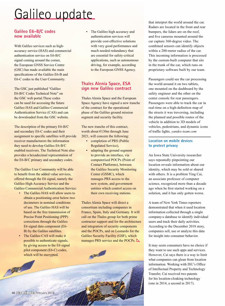
Galileo updateGalileo E6-B/C codes now available
With Galileo services such as high-accuracy service (HAS) and commercial authentication service on E6-B/C signal coming around the corner, the European GNSS Service Centre (GSC) has made available the main specifications of the Galileo E6-B and E6-C codes to the User Community.
The GSC just published “Galileo E6-B/C Codes Technical Note” on the GSC web portal.These codes can be used for accessing the future Galileo HAS and Galileo Commercial Authentication Service (CAS) and can be downloaded from the GSC website.
The description of the primary E6-B/C and secondary E6-C codes and their assignment to specific satellites will provide receiver manufacturers the information they need to develop Galileo E6-B/C enabled receivers. The Technical Note also provides a hexadecimal representation of the E6-B/C primary and secondary codes.
The Galileo User Community will be able to benefit from the added value services, offered through the E6 signal, namely the Galileo High Accuracy Service and the Galileo Commercial Authentication Service:
▪ The Galileo HAS will allow users to obtain a positioning error below two decimeters in nominal conditions of use. The Galileo HAS will be based on the free transmission of Precise Point Positioning (PPP) corrections through the Galileo E6 signal data component (E6-B) by the Galileo satellites.
▪ The Galileo CAS will make it possible to authenticate signals, by giving access to the E6 signal pilot component (E6-C) codes, which will be encrypted.
▪ The Galileo high accuracy and authentication services will provide cost-effective solutions with very good performance and much needed redundancy that are essential for safety-critical applications, such as autonomous driving, for example, according to the European GNSS Agency.
Thales Alenia Space, ESA sign new Galileo contract
Thales Alenia Space and the European Space Agency have signed a new tranche of the contract for the operational phase of the Galileo ground mission segment and security facility.
The new tranche of this contract, worth about €130m through June 2021, will concern the following:
▪ completion of PRS (Public Regulated Service),
▪ adapting the ground segment to provide an interface, via computerised POCPs (Point of Contact Platforms), between the Galileo Security Monitoring Center (GSMC), which manages PRS access to the new system, and government entities which control access on their own receiving stations.
Thales Alenia Space will direct a consortium including companies in France, Spain, Italy and Germany. It will call on the Thales group for both prime contractor support and for the architecture and integration of security components and the POCPs, and on Leonardo for the Galileo Security Facility (GSF), which manages PRS service and the POCPs.
that interpret the world around the car. Radars are located in the front and rear bumpers, the lidars are on the roof, and five cameras mounted around the car capture 360-degree video. The combined sensors can identify objects within a 200-meter radius of the car. This incoming information is processed by the custom-built computer that sits in the trunk of the car, which runs on proprietary software built by our team.
Passengers could see the car processing the world around it on two tablets, one mounted on the dashboard by the safety engineer and the other on the center console for rear passengers. Passengers were able to track the car in real-time on a high-definition map of the streets it was traversing, including the planned and possible routes of the vehicle in addition to 3D models of vehicles, pedestrians, and dynamic icons of traffic lights. yandex-team.com
Location on mobile devices to protect privacy
An Iowa State University researcher says repeatedly pinpointing our location reveals information about our identity, which may be sold or shared with others. It is a problem Ying Cai, an associate professor of computer science, recognized more than a decade ago when he first started working on a solution, and it has only gotten worse.
A team of New York Times reporters demonstrated that when it used location information collected through a single company›s database to identify individual users and track their daily activities. According to the December 2018 story, companies sell, use or analyze this data for insight into consumer behavior.
It may seem consumers have no choice if they want to use such apps and services. However, Cai says there is a way to limit what companies can glean from location information. Working with ISU’s Office of Intellectual Property and Technology Transfer, Cai received two patents for his location-cloaking technology (one in 2014, a second in 2017).
46 | Coordinates February 2019
official Google apps but mere fake ones. Some have been seen just popping up ads on the mobile phone screens of the users.
Indian Railways join hands with ISRO to allow live tracking
Indian Space Research Organisation, ISRO has started working with Indian Railways to track trains and automatically feed the control charts about the train’s arrival and departure.
“A new beginning has been made in the new year: the train movement information is acquired and fed to the control charts using ISRO (Indian Space Research Organisation) satellite-based real-time train information system (RTIS) automatically,” a senior railway ministry official stated.
After the collaborative effort of ISRO and Indian Railways, a satellite-based system will also help railways in mapping the area as well as it will come in handy at the time of accidents when it can be used to ascertain the exact location of trains and topography. www.businessinsider.in
FARO® releases SCENE 2019
FARO® has announced the release of SCENE 2019, an advanced, integrated software platform that optimizes the FARO Focus Laser Scanner product family. SCENE 2019 is specifically designed to evolve the 3D reality capture, analysis and documentation experience across the public safety forensics segment for crash, crime, fire and security planning and Traceable Construction™ for Architecture, Engineering and Construction markets. www.faro.com
Sanborn announces version 2 release of GeoServe™ Lidar Viewer
After 2 years of successful deployment of the GeoServe™ Lidar Viewer and Quality Control (QC) Interface (first announced in 2017), Sanborn has now added new features to enhance clients’ ability to view and analyze lidar point cloud data immediately after initial processing.
The GeoServe™ Lidar Viewer and QC Interface serves point cloud data through a user-friendly, web-based interface from a secure cloud environment. The Sanborn GeoServe™ Lidar Viewer delivers the following benefits:
▪ Provides ease and standard documentation for data quality review needed for contract monitoring and compliance
▪ Facilitates coordination between many data reviewers, even when geographically separated
▪ Instant access to online point cloud data for review by Sanborn Lidar clients
And several more.. www.sanborn.com
Aerial LiDAR uses to measure snow cover
In a new study published in Remote Sensing of the Environment, an interdisciplinary team of researchers from
Desert Research Institute (DRI), the University of Nevada, Reno (UNR), the California Institute of Technology’s Jet Propulsion Laboratory, and California State University described the first successful use of lidar to measure snow cover under forested canopy in the Sierra Nevada. In this study, researchers worked with NASA’s Airborne Snow Observatory to collect lidar data in the Sagehen Creek watershed of the Sierra Nevada by aircraft on three dates during the spring of 2016 when snow was present.
Analysis of the datasets revealed that the lidar was, in fact, capable of detecting snow presence or absence both under canopy and in open areas, so long as areas with low branches were removed from the analysis. On-the-ground measurements used distributed temperature sensing with fiber optic cables laid out on the forest floor to verify these findings.
The technology makes it possible to search and use apps on mobile devices while keeping your privacy under control. The concept behind the technology is simple: to provide a location that is as precise as possible, but still sufficient to protect the user›s privacy. Specifically, users give examples of locations matching their personal privacy level. Cai says service providers then use that information to calculate a cloaking region with a similar popularity. https://phys.org
OnTerra Systems introduces low-cost GPS fleet tracking
OnTerra Systems, developers of RouteSavvy route optimization software has announced the availability of innovative, cost-effective GPS tracking for small to mid-sized fleets using the driver’s mobile device (cell phones or tablets). This innovative technical approach allows small to mid-sized fleets access to GPS tracking at a fraction of the cost of typical GPS fleet tracking technology. This new, affordable GPS Fleet Tracking technology works as part of the RouteSavvy web
application for displaying driver location and history. OnTerra System’s new GPS Fleet Tracker features allow managers of small to mid-sized fleets to track and monitor vehicles in the fleet via cell phones. www.RouteSavvy.com
Fake GPS navigation app detected on Google Play Store
A malware expert with ESET, Lucas Stefank has detected that there are apps operating in the Google environment which borrow inputs from Google Maps app and then peddles them to its customers for a fee!
Google, however, quickly reacted and moved in to do damage control. Many of the apps identified by Stefanko have since been removed from the Play Store.
A majority of them this time are in the GPS and navigational systems areas. And these apps have already been downloaded and are used by over 50 million users worldwide. These people would not have known that what they are using are not
NEWS - LIDAR
Coordinates February 2019 | 47
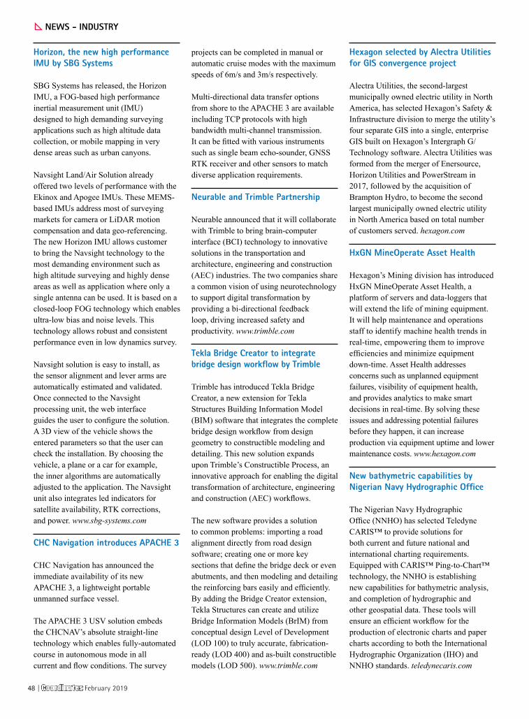
NEWS - INDUSTRY
Horizon, the new high performance IMU by SBG Systems
SBG Systems has released, the Horizon IMU, a FOG-based high performance inertial measurement unit (IMU) designed to high demanding surveying applications such as high altitude data collection, or mobile mapping in very dense areas such as urban canyons.
Navsight Land/Air Solution already offered two levels of performance with the Ekinox and Apogee IMUs. These MEMS-based IMUs address most of surveying markets for camera or LiDAR motion compensation and data geo-referencing. The new Horizon IMU allows customer to bring the Navsight technology to the most demanding environment such as high altitude surveying and highly dense areas as well as application where only a single antenna can be used. It is based on a closed-loop FOG technology which enables ultra-low bias and noise levels. This technology allows robust and consistent performance even in low dynamics survey.
Navsight solution is easy to install, as the sensor alignment and lever arms are automatically estimated and validated. Once connected to the Navsight processing unit, the web interface guides the user to configure the solution. A 3D view of the vehicle shows the entered parameters so that the user can check the installation. By choosing the vehicle, a plane or a car for example, the inner algorithms are automatically adjusted to the application. The Navsight unit also integrates led indicators for satellite availability, RTK corrections, and power. www.sbg-systems.com
CHC Navigation introduces APACHE 3
CHC Navigation has announced the immediate availability of its new APACHE 3, a lightweight portable unmanned surface vessel.
The APACHE 3 USV solution embeds the CHCNAV’s absolute straight-line technology which enables fully-automated course in autonomous mode in all current and flow conditions. The survey
projects can be completed in manual or automatic cruise modes with the maximum speeds of 6m/s and 3m/s respectively.
Multi-directional data transfer options from shore to the APACHE 3 are available including TCP protocols with high bandwidth multi-channel transmission. It can be fitted with various instruments such as single beam echo-sounder, GNSS RTK receiver and other sensors to match diverse application requirements.
Neurable and Trimble Partnership
Neurable announced that it will collaborate with Trimble to bring brain-computer interface (BCI) technology to innovative solutions in the transportation and architecture, engineering and construction (AEC) industries. The two companies share a common vision of using neurotechnology to support digital transformation by providing a bi-directional feedback loop, driving increased safety and productivity. www.trimble.com
Tekla Bridge Creator to integrate bridge design workflow by Trimble
Trimble has introduced Tekla Bridge Creator, a new extension for Tekla Structures Building Information Model (BIM) software that integrates the complete bridge design workflow from design geometry to constructible modeling and detailing. This new solution expands upon Trimble’s Constructible Process, an innovative approach for enabling the digital transformation of architecture, engineering and construction (AEC) workflows.
The new software provides a solution to common problems: importing a road alignment directly from road design software; creating one or more key sections that define the bridge deck or even abutments, and then modeling and detailing the reinforcing bars easily and efficiently. By adding the Bridge Creator extension, Tekla Structures can create and utilize Bridge Information Models (BrIM) from conceptual design Level of Development (LOD 100) to truly accurate, fabrication-ready (LOD 400) and as-built constructible models (LOD 500). www.trimble.com
Hexagon selected by Alectra Utilities for GIS convergence project
Alectra Utilities, the second-largest municipally owned electric utility in North America, has selected Hexagon’s Safety & Infrastructure division to merge the utility’s four separate GIS into a single, enterprise GIS built on Hexagon’s Intergraph G/Technology software. Alectra Utilities was formed from the merger of Enersource, Horizon Utilities and PowerStream in 2017, followed by the acquisition of Brampton Hydro, to become the second largest municipally owned electric utility in North America based on total number of customers served. hexagon.com
HxGN MineOperate Asset Health
Hexagon’s Mining division has introduced HxGN MineOperate Asset Health, a platform of servers and data-loggers that will extend the life of mining equipment. It will help maintenance and operations staff to identify machine health trends in real-time, empowering them to improve efficiencies and minimize equipment down-time. Asset Health addresses concerns such as unplanned equipment failures, visibility of equipment health, and provides analytics to make smart decisions in real-time. By solving these issues and addressing potential failures before they happen, it can increase production via equipment uptime and lower maintenance costs. www.hexagon.com
New bathymetric capabilities by Nigerian Navy Hydrographic Office
The Nigerian Navy Hydrographic Office (NNHO) has selected Teledyne CARIS™ to provide solutions for both current and future national and international charting requirements. Equipped with CARIS™ Ping-to-Chart™ technology, the NNHO is establishing new capabilities for bathymetric analysis, and completion of hydrographic and other geospatial data. These tools will ensure an efficient workflow for the production of electronic charts and paper charts according to both the International Hydrographic Organization (IHO) and NNHO standards. teledynecaris.com
48 | Coordinates February 2019
Sokkia introduces integrated receiver for diverse applications
Sokkia has introduced the latest addition to its GNSS integrated receiver line — the GRX3 is designed to provide a smaller, lighter and fully integrated GNSS solution. The receiver features Sokkia Tilt technology, which includes a 9-axis inertial measurement unit (IMU) and ultra-compact eCompass designed to compensate for mis-leveled field measurements by as much as 15 degrees. Sokkia.com
DT Research GNSS rugged tablets by Oregon DoT
DT Research, the leading designer and manufacturer of purpose-built computing solutions for vertical markets, announced the Oregon Department of Transportation (ODOT) has expanded its use of DT Research GNSS rugged tablets to all 15 of its construction management offices across the state and also use the tablets for biology, geology, roadway and wetland projects. DT Research worked closely with ODOT to design purpose-built rugged tablets that empower state workers to easily collect and transmit geospatial measurements in the field using GNSS Real Time Kinematic (RTK) technologies.
Allystar launches multi-band, multi-GNSS chip for devices
Allystar Technology Co. Ltd. has launched a multi-band, multi-GNSS system on chip, the HD8040 series, to help portable devices save size and weight. The HD8040 offered in wafer-level chip-scale packaging (WLCSP). The HD8040 series of chipsets fully supports all civil signals on the L5 band, said Shi Xian Yang, Allystar high-precision product manager. Besides GPS, other constellations with L1/L5 signals include Galileo, BeiDou, the Indian NavIC system and Japanese QZSS.
Spirent’s SimMNSA granted security approval by the GPS directorate
Spirent Federal Systems has announced that their new M-Code solution, SimMNSA, has been granted Security Approval by the Global Positioning System Directorate. They are the first and only
company to provide this highly anticipated solution for simulating classified GPS signals, and are currently taking orders.
In 2017, Spirent Federal Systems partnered with Rockwell Collins to develop new software that will use the Modernized Navstar Security Algorithm (MNSA). This new approach of M-Code simulation adds to Spirent Federal’s portfolio of classified signal simulation solutions, and will be available to authorized users of the GSS9000 series simulators.
Drone Delivery Canada supports Transport Canada
Drone Delivery Canada ‘DDC has expressed its support for the new Remotely Piloted Aircraft regulations recently announced. These regulations are specific to drones used in Visual Line of-Site operations, may not necessarily be applicable to DDC’s Beyond Visual Line-of-Site (BVLOS) initiatives. However, DDC believes the Canadian drone industry requires this type of stable and flexible regulatory regime to allow the industry to flourish, while at the same time, having the flexibility to continue expanding its field of influence. www.dronedeliverycanada.com
Handheld launches new NAUTIZ X6
Handheld Group has announced the new NAUTIZ X6 – an ultra-rugged phablet-phone plus tablet— that combines the big-screen functionality of a tablet with the go-anywhere performance of a rugged phone. The new Nautiz X6 Android phablet is ideal for industrial and field applications, with the reliability to perform in challenging conditions, and specialized accessories professional users require. www.handheldgroup.com
NovAtel to deliver signal generators for FAA’s WAAS navigation plans
NovAtel has secured a contract from the US Federal Aviation Administration (FAA) to design, produce and supply 40 next-generation ground uplink station (GUS) signal generators The GUS signal generators will be used to support the FAA’s safety-of-life Wide Area Augmentation
System (WAAS) air navigation service. In addition, the contract includes engineering support services for NovAtel’s portfolio of satellite-based augmentation system (SBAS) products deployed by the FAA, including the WAAS G-III reference receiver platform. The WAAS network has been developed by the FAA. It is used as a navigation aid that allows aircraft to use the US GPS for all phases of flight. Every time a plane takes off or lands within the WAAS coverage area, NovAtel technology will generate and process data to help pilots make precision approaches to any airport. www.airport-technology.com
Petite new spoofing detector
An Israeli firm is introducing a technology to detect the spoofing of GPS and other satellite navigation signals that is packaged into a device so small it can be integrated into existing receivers for drones, ships and autonomous vehicles — and, soon, maybe even cell phones. Haifa-based Regulus Cyber has demonstrated its Pyramid GNSS product at the Consumer Electronics Show last month. The palm-sized device can be incorporated with existing receivers — including those for mobile and Internet of Things (IoT) devices — receiving signals from GPS or the other GNSSs.
Safe high-precision GNSS positioning
Septentrio, a leader in high-precision GNSS technology, and Sapcorda, specialized in safe broadcasted GNSS correction services, are pleased to announce live demonstration of a safe high-accuracy positioning and correction solution for automated driving. The companies have combined their respective technologies to deliver the benefits of SSR (Space State Representation) technology seamlessly to OEM automakers and Tier1 integrators. These benefits include decimeter-accuracy within seconds, anywhere over an entire continent, to support autonomy levels from lane keeping to full autonomy in a totally homogeneous coverage. The GNSS augmentation service is scalable through simple broadcast corrections, and safety-awareness is provided via Sapcorda’s unique integrity concept and Septentrio’s integrity monitoring engine. septentrio.com
Coordinates February 2019 | 49
MARK YOUR CALENDAR
GISTAM 20195th International Conference on Geographical Information Systems Theory, Applications and Management
3-5 May 2019Heraklion, Crete, Greecewww.gistam.org
June 2019HxGN LIVE 2019
11 - 14 JuneLas Vegas, USAhttps://hxgnlive.com/2019
TransNav 201912 - 14 JuneGdynia, Poland http://transnav.am.gdynia.pl
July 2019Esri User Conference
8 - 12 July San Diego, Californiawww.esri.com
August 2019The South-East Asia Survey Congress(SEASC) 2019
15 - 19 AugustDarwin, Australiahttps://sssi.org.au
September 2019GI4DM
3 - 6 SeptemberPrague, Czech Republicwww.gi4dm2019.org
Intergeo 201917 - 19 SeptemberStuttgart, Germanywww.intergeo.de
ION GNSS+201916 - 20 September Miami, Florida, USAwww.ion.org
MRSS19 - Munich Remote Sensing Symposium 2019
18 - 20 September Munich, Germanywww.mrss.tum.de
ISDE 1124 - 27 September Florence, Italydigitalearth2019.eu
Interdrone3-6 September 2019Las Vegas, USAwww.interdrone.com
October 2019Commercial UAV Expo Americas
28 - 30 OctoberLas Vegas, USAwww.expouav.com
March 20192019 URSI Asia Pacific Radio Science Conference
9 - 15 MarchNew Delhi, Indiawww.aprasc2019.com
Munich Satellite Navigation Summit 25 - 27 March Munich, Germanywww.munich-satellite-navigation-summit.org
Land and Poverty Conference 201925 - 29 MarchWashington, DC, USAwww.worldbank.org
April 2019Commercial UAV Expo Europe
8-10 April Amsterdam, the Netherlandswww.expouav.com/europe
Pacific PNT8-11, AprilHonolulu, HI USAwww.ion.org
European Navigation Conference 20199 - 12 AprilWarsaw, Polandhttp://enc2019.eu
FIG Working Week 201922 - 26 AprilHanoi, Vietnamwww.fig.net/fig2019
XIII International Navigation Forum & NAVITECH-2019
23 - 26 April Moscow, Russiahttp://glonass-forum.com
AUVSI Xponential 201929 April - 2 May Chicago, United Stateswww.auvsi.org/events/xponential/auvsi-xponential-2019
May 201913th Annual Baska GNSS Conference,
5 - 8 MayBaska, Croatia
4th Joint International Symposium on Deformation Monitoring and Analysis
15 - 17 May Athens, Greecehttp://jisdm2019.survey.ntua.gr
Geo Business 201921 - 22 MayLondon, UKwww.GeoBusinessShow.com
First name .........................................................................
Last name ..........................................................................
Designation .......................................................................
Organization .....................................................................
Address ...............................................................................
...............................................................................................
City ................................... Pincode .................................
State ................................ Country .................................
Phone .................................................................................
Fax .......................................................................................
Email ...................................................................................
I enclose cheque no. ......................................................
drawn on ...........................................................................
date .................................. towards subscription
charges for Coordinates magazine
in favour of ‘Coordinates Media Pvt. Ltd.’
Sign .................................. Date .......................................
Mail this form with payment to:
CoordinatesA 002, Mansara Apartments
C 9, Vasundhara Enclave
Delhi 110 096, India.
If you’d like an invoice before sending your
payment, you may either send us this completed
subscription form or send us a request for
an invoice at [email protected]
YES! I want my
I would like to subscribe for (tick one)
Rs.1800/US$100 Rs.3000/US$170 Rs.4300/US$240
50 | Coordinates February 2019

Focusing on true performance!
www.pentaxsurveying.com/en/
TI Asahi Co., Ltd.International Sales Department 4-3-4 Ueno Iwatsuki-Ku, Saitama-ShiSaitama, 339-0073 Japan
Tel.: +81-48-793-0118Fax: +81-48-793-0128E-mail: [email protected]
www.lawrenceandmayo.co.in
Authorized Distributor in IndiaLawrence & Mayo Pvt. Ltd.274, Dr. Dadabhai Naoroji Rd.Mumbai 400 001 India
Tel.: +91 22 22 07 7440 Fax: +91 22 22 07 0048 E-mail: [email protected]
R-1500N & R-2800N
Reflectorless Total StationsTotal surveying solutions
W-1500N & W-2800
Windows CE Total StationsTruly integrated systems
S-3180V
Scanning System3D laser measurement system
GNSS ReceiversPrecision Satellite Surveying with wireless communications
G6 Ti |Ni
D-600
Precise Aerial Imaging System6 Rotor Multicopter with Autopilot

The most powerful LabSat yet, the new
LabSat 3 WIDEBAND captures and replays
more GNSS signals at a much higher resolution than
before.
Small, battery powered and with a removable solid state disk,
LabSat 3 WIDEBAND allows you to quickly gather detailed,
real world satellite data and replay these signals on your bench.
With three channels, a bandwidth of up to 56MHz and 6 bit
sampling, LabSat 3 WIDEBAND can handle almost any
combination of constellation and signal that exists today, with plenty
of spare capacity for future planned signals.
LabSat 3 WIDEBAND can record and replay the following
signals:
• GPS: L1 / L2 / L5
• GLONASS: L1 / L2 / L3
• BeiDou: B1 / B2 / B3
• QZSS: L1 / L2 / L5
• Galileo: E1 / E1a / E5a / E5b / E6
• SBAS: WAAS, EGNOS , GAGAN, MSAS, SDCM
• IRNSS www.labsat.co.uk
record replay simulate
Related Documents