Real-time Asset Creation Guidelines Version 1.0.0 Last Updated: October 20, 2020 Copyright 2020 The Khronos® Group Inc. This Document is protected by copyright laws and contains material proprietary to Khronos. Except as described by these terms, it or any components may not be reproduced, republished, distributed, transmitted, displayed, broadcast or otherwise exploited in any manner without the express prior written permission of Khronos. Khronos grants a conditional copyright license to use and reproduce the unmodified Document for any purpose, without fee or royalty, EXCEPT no licenses to any patent, trademark or other intellectual property rights are granted under these terms. Khronos makes no, and expressly disclaims any, representations or warranties, express or implied, regarding this Document, including, without limitation: merchantability, fitness for a particular purpose, non-infringement of any intellectual property, correctness, accuracy, completeness, timeliness, and reliability. Under no circumstances will Khronos, or any of its Promoters, Contributors or Members, or their respective partners, officers, directors, employees, agents or representatives be liable for any damages, whether direct, indirect, special or consequential damages for lost revenues, lost profits, or otherwise, arising from or in connection with these materials. Khronos® and Vulkan® are registered trademarks, and ANARI™, WebGL™, glTF™, NNEF™, OpenVX™, SPIR™, SPIR-V™, SYCL™, OpenVG™ and 3D Commerce™ are trademarks of The Khronos Group Inc. OpenXR™ is a trademark owned by The Khronos Group Inc. and is registered as a trademark in China, the European Union, Japan and the United Kingdom. OpenCL™ is a trademark of Apple Inc. and OpenGL® is a registered trademark and the OpenGL ES™ and OpenGL SC™ logos are trademarks of Hewlett Packard Enterprise used under license by Khronos. ASTC is a trademark of ARM Holdings PLC. All other product names, trademarks, and/or company names are used solely for identification and belong to their respective owners.

Welcome message from author
This document is posted to help you gain knowledge. Please leave a comment to let me know what you think about it! Share it to your friends and learn new things together.
Transcript

Real-time Asset Creation GuidelinesVersion 1.0.0Last Updated: October 20, 2020
Copyright 2020 The Khronos® Group Inc.
This Document is protected by copyright laws and contains material proprietary to Khronos. Exceptas described by these terms, it or any components may not be reproduced, republished, distributed,transmitted, displayed, broadcast or otherwise exploited in any manner without the express priorwritten permission of Khronos.
Khronos grants a conditional copyright license to use and reproduce the unmodified Document forany purpose, without fee or royalty, EXCEPT no licenses to any patent, trademark or otherintellectual property rights are granted under these terms.
Khronos makes no, and expressly disclaims any, representations or warranties, express or implied,regarding this Document, including, without limitation: merchantability, fitness for a particularpurpose, non-infringement of any intellectual property, correctness, accuracy, completeness,timeliness, and reliability. Under no circumstances will Khronos, or any of its Promoters,Contributors or Members, or their respective partners, officers, directors, employees, agents orrepresentatives be liable for any damages, whether direct, indirect, special or consequentialdamages for lost revenues, lost profits, or otherwise, arising from or in connection with thesematerials.
Khronos® and Vulkan® are registered trademarks, and ANARI™, WebGL™, glTF™, NNEF™,OpenVX™, SPIR™, SPIR-V™, SYCL™, OpenVG™ and 3D Commerce™ are trademarks of The KhronosGroup Inc. OpenXR™ is a trademark owned by The Khronos Group Inc. and is registered as atrademark in China, the European Union, Japan and the United Kingdom. OpenCL™ is a trademarkof Apple Inc. and OpenGL® is a registered trademark and the OpenGL ES™ and OpenGL SC™ logosare trademarks of Hewlett Packard Enterprise used under license by Khronos. ASTC is a trademarkof ARM Holdings PLC. All other product names, trademarks, and/or company names are used solelyfor identification and belong to their respective owners.

Editors and AlumniListed in alphabetical order of campany names
EditorsBrent Scannell, AutodeskSam De Lara, 3XRMike Festa, 3XRMax Limper, DGGNathaniel Hunter, DreamView3D Commerce Asset Creation TSG, Khronos GroupMike Badillo, SamsungThomas Huang, TargetJagdishwar Jaman Jyothi, TargetEric Chadwick, Wayfair
AlumniBeau Perschall, TurboSquid

ContentReal-time Asset Creation Guidelines Summary
Executive SummaryFile Formats and Asset StructureCoordinate Systems and ScaleGeometryUV CoordinatesMaterialsTexturesRendering and LightingLevels of DetailPublishing TargetsglTF and USDZ
Executive Summary
The goal of these guidelines is to enable artists to streamline the creation of 3D assets that can be easily andreliably used by merchants for real-time rendering on multiple delivery platforms.
This summary is a preview of an upcoming full set of guidelines that will contain many more details, togetherwith example 3D asset creation workflows using popular 3D tools. This summary has been released to enablefeedback and suggestions from the industry to guide and help improve the content of the full guidelines.
These guidelines are primarily intended for 3D artists who are familiar with polygonal 3D workflows but whomay not be familiar with creating assets for 3D web/mobile delivery. They contain best practices andmodeling standards for high-quality, efficient 3D assets that will be performant in augmented reality (AR) andvirtual reality (VR) experiences, product configurators, and interactive web-based 3D marketing tools.
We've designed the guidelines to be DCC (Digital Content Creation) tool agnostic as the principles should beapplicable to any 3D asset creation software. Selected industry-vertical and software specific workflows,including creating 3D assets from true-geometry CAD models will be covered by upcoming Asset CreationWorkflows in the full version of the guidelines.
File Format and Asset Structure
Version 1.0.0Last Updated: October 20, 2020
When building 3D assets, it is important to export the final product models into widely recognized file formatsand to structure data within those files using common conventions.
glTF is a royalty-free, open standard file format for 3D assets that is widely adopted by 3D authoring tools andviewers on diverse platforms. glTF enables asset materials to use Physically Based Rendering (PBR) for realisticvisual product representations. glTF assets are represented as .gltf files with referenced textures & geometry,or binary .glb files that embed the textures directly instead of referencing them as external images.

iOS devices do not natively support glTF but use Apple's proprietary USDz format. glTF and USDz have similarcapabilities but some glTF features are not supported by USDz. For details please refer to the section - glTF2.0 Features / Extensions & USDZ Comparison.
To support these differences we recommend using the Publishing Targets workflow. Using this system aSource Asset is created with the highest quality content in PBR format. This asset can then bedecimated/simplified into different targets, to support a variety of viewers, each supporting different materialfeatures. For example, glTF supports the use of an Emissive value or texture, whereas USDz only supports anEmissive texture.
Best Practice for File SizeThe file size is usually composed of geometry and textures. In the runtime asset scenario, usually thetextures tend to hold more percentage of the total file size. It’s desirable to have the asset file size assmall as possible, which helps in reducing download time and creating smoother guest experience.Ultimately it’s a balancing act between maintaining small file size versus optimal visual quality.With the advancement of hardware capability, more powerful platforms and faster transmission speed,the definition of ideal file size changes over time. Across the industry, our observation is that thestandard range for runtime assets vary from 3 MB to 15 MB.It is also recommended to use compressed textures to keep the texture size to optimum, for instance,using JPG or compressed PNG. See the Christmas stockings image below as an example. In the nearfuture, the new GPU textures such as KTX2 will be part of the toolings to handle the texture part ofasset consideration.See Publishing Targets section.
Best Practice for Asset Preparation
Asset Anatomy
Clean/ Freeze transform data: During the modeling process or converting the asset across differentDCC tools, there may be remnant transform data (rotation, translation and scale). Cleaning up thetransform data helps ensure reliable behaviour, and is critical for animation.
Grouping/Hierarchy: proper grouping hierarchy (scene graph) to organize components of a model tobe a self-contained asset
Consistent naming convention: consistent naming for the components (group nodes, materials,meshes, etc.) with proper prefixes and suffixes
Pivot placement for each component: place the pivot points of meshes and group nodes withintention. Place the pivots where the hinges are for movement control, for instance. Otherwise, it’srecommended to place the pivots of the group nodes or meshes all at the world center (0,0,0). Thetop group node of the asset should be placed at world (0,0,0). To better illustrate the point, here’s anexample of a TV shelf and how it is prepared (Figure 1.1).
Scene graph of the TV Stand model: it has a top group node which includes several geometrycomponents.The scene graph illustrates the consistent naming rule that describes the components and theasset itself.

The red axes visualize where the pivot points are for the cabinet doors, easier of animation/movement. The asset main pivot point (the big red aexis) is at the world center (0,0,0)
(C)2020, Target. License: CC BY 4.0 International Figure 1.1: pivot placement
Asset Geometry
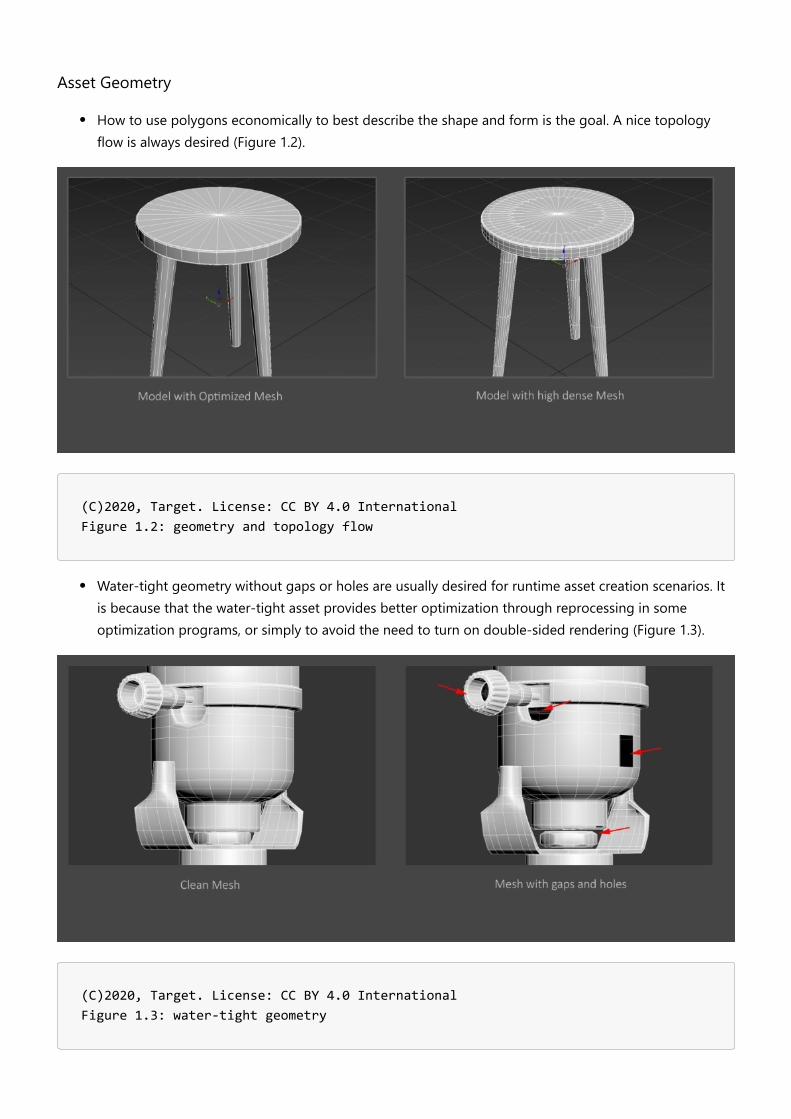
How to use polygons economically to best describe the shape and form is the goal. A nice topologyflow is always desired (Figure 1.2).
(C)2020, Target. License: CC BY 4.0 International Figure 1.2: geometry and topology flow
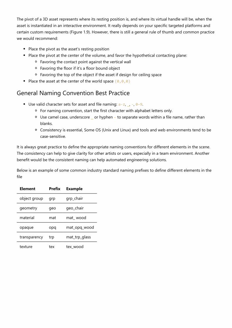
Water-tight geometry without gaps or holes are usually desired for runtime asset creation scenarios. Itis because that the water-tight asset provides better optimization through reprocessing in someoptimization programs, or simply to avoid the need to turn on double-sided rendering (Figure 1.3).
(C)2020, Target. License: CC BY 4.0 International Figure 1.3: water-tight geometry

Avoid N-gons and non-planar faces, only use Quad mesh or Triangle meshes. It’s recommended toavoid long- thin triangular faces, as it would be more expensive to draw in GPU (Figure 1.4).
(C)2020, Target. License: CC BY 4.0 International Figure 1.4: avoid N-gons and non-planar faces
UV layout in a 0-to-1 space, should maximize texture space as possible (Figure 1.5)
(C)2020, Target. License: CC BY 4.0 International Figure 1.5: maximize texture space in UV layout

Asset Textures
Another common and effective practice to reduce the polygon mesh is to bake the detailed high-polymesh to normal map and apply it to a lower-density mesh to reduce the vertex count (Figure 1.6)
(C)2020, Target. License: CC BY 4.0 International Figure 1.6: use of normal map to describe details
To avoid visible seams around the UV border in an asset, textures should have edge dilation to avoidseams during MIP mapping (Figure 1.7)
(C)2020, Target. License: CC BY 4.0 International Figure 1.7: maximize texture space in UV layout

Use compressed textures (e.g. JPEG) to keep file size smaller; or use PNG if alpha information isrequired - e.g. Base Color texture with Alpha Coverage information (Figure 1.8).
(C)2020, Target. License: CC BY 4.0 International Figure 1.8: optimize textures with compression
Dealing with opaque and transparent components in an asset - It is preferred to use separate materialsto describe transparent and opaque objects.It is always good to consider and design your assets based on the targeted viewers. It is critical tounderstand what format features (e.g. glTF 2.0) may or may not be supported at this moment -- likevertex color, extra uv sets, animation, cameras, etc.
Asset Pivot Point (Placement, hanging points)
(C)2020, Target. License: CC BY 4.0 International Figure 1.9: asset pivot point placement
The pivot of a 3D asset represents where its resting position is, and where its virtual handle will be, when theasset is instantiated in an interactive environment. It really depends on your specific targeted platforms andcertain custom requirements (Figure 1.9). However, there is still a general rule of thumb and common practicewe would recommend:
Place the pivot as the asset’s resting positionPlace the pivot at the center of the volume, and favor the hypothetical contacting plane:
Favoring the contact point against the vertical wallFavoring the floor if it’s a floor bound objectFavoring the top of the object if the asset if design for ceiling space
Place the asset at the center of the world space (0,0,0)
General Naming Convention Best PracticeUse valid character sets for asset and file naming: a-z, _, -, 0–9.
For naming convention, start the first character with alphabet letters only.Use camel case, underscore _ or hyphen - to separate words within a file name, rather thanblanks.Consistency is essential, Some OS (Unix and Linux) and tools and web environments tend to becase-sensitive.
It is always great practice to define the appropriate naming conventions for different elements in the scene.The consistency can help to give clarity for other artists or users, especially in a team environment. Anotherbenefit would be the consistent naming can help automated engineering solutions.
Below is an example of some common industry standard naming prefixes to define different elements in thefile
Element Prefix Example
object group grp grp_chair
geometry geo geo_chair
material mat mat_ wood
opaque opq mat_opq_wood
transparency trp mat_trp_glass
texture tex tex_wood

Coordinate System and Scale UnitVersion 1.0.0Last Updated: Oct 20, 2020
World up, front, and scale unitsDepending on what 3D software you use, each software comes with a different interpretation of coordinatesystems and measurement units. Some software uses +Z axis as world up with right hand coordinate system,while others use +Y as world up with left/right hand coordinate system. It also matters whether the softwareuses right-hand or left-hand coordinate system. For scale units, there may be differences based on specificproduction workflows, or the default environment defined by the software - inch, centimeter, or meter-basedunit, etc.
It is typical that we may need to deal with a number of different coordinate systems and scale units during theproduction process. Luckily, when converting to runtime file formats glTF and USDZ, both formats do havestandardized settings the assets need to comply with. Both glTF and USDZ use +Y world up, +Z world front,right-hand coordinate system, and both are meter-based scale standard.
glTFFor more details regarding glTF2.0 specifications:
https://github.com/KhronosGroup/glTF/tree/master/specification/2.0
Coordinate System and Units
glTF uses a right-handed coordinate system, that is, the cross product of +X and +Y yields +Z. In glTF +Y isworld up, and the front of a glTF asset faces +Z. The units for all linear distances are meters. All angles are inradians and positive rotation is counterclockwise. See the BoomBox example here (Figure 1.1).
License: CC BY 4.0 International Modified from source: https://github.com/KhronosGroup/glTF-Sample-Models/tree/master/2.0/BoomBox Figure 2.1: coordinate system

Normal Maps and glTF
According to the GLTF2.0 specifications, the normal vectors use OpenGL conventions where +X is right and +Yis up. +Z points toward the viewer.
USDZFor more details regarding USDZ:
https://graphics.pixar.com/usd/docs/Usdz-File-Format-Specification.html
According to Apple ARKit documentation, “ARKit uses world and camera coordinate systems following aright-handed convention: the y-axis points upward, and (when relevant) the z-axis points toward the viewerand the x-axis points toward the viewer's right.”
Normal Maps and USDZ
In USDz, normal vectors use OpenGL conventions where +X is right and +Y is up. +Z points toward the viewer.
USDFor more details regarding USD:
https://graphics.pixar.com/usd/docs/index.html
https://graphics.pixar.com/usd/docs/api/group___usd_geom_up_axis__group.html
“The stage up axis is encoded as stage metadatum upAxis, whose legal values are Y and Z, as represented byUsdGeomTokens -> y and UsdGeomTokens -> z. Of course, constructing a correct camera view of a scenedepends not only on the up axis, but also on the handedness of the coordinate system. Like OpenGL and thefallback for UsdGeomGprim::GetOrientationAttr(), UsdGeom stipulates a right-handed coordinate system.Therefore, when viewing a UsdStage with a Y up axis, the stage's Z axis will be pointing out of the screen, andwhen viewing a UsdStage with a Z up axis, the stage's Y axis will be pointing into the screen.”
In summary, here are some high-level take-away regarding the following formats:
Format glTF USDZ USD
CoordinateSystem
right-handed
right-handed right-handed
World Up +Y +Y +Y or +Z
WorldFront
+Z +Z +Z or +Y
Scale Unit MeterMeter (metersPerUnit =meter, else centimeter)
Meter (Stage-level metadata that encodes a scene'slinear unit of measure as meters per encoded unit.)

GeometryVersion 1.0.0Last Updated: October 20, 2020
A geometric mesh is a structural build of a 3D model that is created using a combination of polygons. Theyhelp define the size and shape of a model.
(C)2020, 3XR Inc. License: CC BY 4.0 International Figure 3.1: Wireframe model of a modern vacuum.
It is best to design 3D models with high accuracy and quality, which can then be tailored for productrendering, or later optimized as real-time assets for real-time applications. To function on the web and mobiledevices, it is important to ensure that models load quickly and that they are highly optimized. If a model is notmade efficiently, it can dramatically impact the experience downstream.
ReferencePhotorealistic models should look identical to the original product in reality. Having and using referencephotos from many angles as well as product measurements, helps ensure that a model will be as accurate aspossible.

(C)2020, 3XR Inc. License: CC BY 4.0 International Figure 3.2: Piano Geometry & Reference Photos.
Make sure models are built to real world scale, so they can be used immediately without having any scalingissues. If a model is not properly scaled, it can interfere with its surroundings or not function properly. Keep inmind that current GLTF/USDZ converters and exporters sometimes rely on having 3D models being set up inmeters. Be sure to understand what your exporter is doing to your model regarding scale once completed andbefore implementation.
Quads & Tris
(C)2020, 3XR Inc. License: CC BY 4.0 International Figure 3.3: Quad Geometry vs Triangle Geometry.

The geometry of a model is represented by vertices, which are points in 3D space, that are connected byedges. Those edges form faces that can either be 3 sided (tris) or 4 sided (quads). 4 sided quads are notactually supported in GLTF and will throw a warning on submission. It is recommended that you use quadswhile creating your model and using this mesh as your main source. Leave triangulation of your object to bethe last step of model creation. Some software allows for faces with more than 5 sides (n-gons), but n-gonsare not recommended because there can be some ambivalence as to how they get drawn in the viewer.
When models are rendered in a viewer, each triangle that is visible on the screen gets painted usinginformation in the texture maps. Models that have quads are split in half into triangles during rendering, so itis the triangle count of the model that impacts performance.
Topology & Mesh OptimizationWhen creating a model, a mesh should strive to use every polygon in an efficient manner.
Topology is the organization, flow, and structure of the polygons of a 3D model. It is how each vertice, edge,and face are set up in order to create a model.
Every model should have proper topology to minimize the visual errors that it would have in the viewer.Single vertex points that have a large number of edges connected to them should be avoided when possible.
(C)2020, 3XR Inc. License: CC BY 4.0 International Figure 3.4: Main source mesh topology on a couch model.
There should be no black polygons on the model. Black polygons are a sign that something has gone wrongwith the model, such as two faces overlapping or normals need to be recalculated. In some software, this kindof error can appear as part of a mesh looking “inside-out” or not showing up at all on the mesh.

Bevel all product edges to smooth out edge transitions. There are no perfectly pointed edges in everyday lifeand your model should reflect this. A model that has a too little number of polygons on a normally veryrounded edge can seem unrealistically sharp.
(C)2020, 3XR Inc. License: CC BY 4.0 International Figure 3.5: Coffee maker body is too polygonally sharp without more edges added.

Mesh Optimization Workflow : how to optimize a model
(C)2020, 3XR Inc. License: CC BY 4.0 International Figure 3.6: Individual components modeled, then constructed together.
Create 3D models as if you were building the real product. We do not advise creating a very complex modelfrom a singular mesh. Model all the individual pieces of a model separately.
Polygonal CountModels should only have as much geometry as necessary to keep a high level of realism. The more triangles,the more calculations that need to be computed when rendering. Normal map textures should be used tocapture small details that may be modeled in a base asset in order to reduce the triangle count while retainingvisual fidelity.
For further information about specific publishing targets, refer to the Publishing Targets section of thisdocument.
Normal MapsNormal maps may be used to approximate 3 dimensional surface details during rendering without requiringactual geometry to interact with scene lighting. Compared to using face or vertex based normals to calculatelight interaction, which is limited to the density of the mesh being rendered, a normal map represents normaldata on a surface by storing normal vectors in the RGB channels of a bitmap that is mapped on the samesurface. The result is an ability to store normal data at a much higher resolution, limited only by bitmap pixelresolution. \

(C)2020, 3XR Inc. License: CC BY 4.0 International Figure 3.7: Normal map used to create ridges at the back of a coffee machine.
Same asset high/low res example
Workflow: How to make normal maps..
See bump texture in materials section
See normal map considerations for glTF and USD formats
Ideally we would take into account all the considerations in this article. Needs coordination with certification.https://medium.com/@bgolus/generating-perfect-normal-maps-for-unity-f929e673fc57
Platform-Based LODsMobile web-based augmented reality should have the most optimized 3D models as compared to virtualreality models. The more powerful a machine is to process your model, the greater the file size of your modelcan be. When creating models of a product, it is best to follow best to produce an accurate, high-qualitymodel that can account for being used in various platforms. For further information on LODs and what theyare, refer to the LODs section of this document.
For further information about specific recommended publishing targets, refer to the Publishing Targetssection of this document.
Separate vs. Combined Meshes
Opaque vs. Transparencies
Sections of models that have transparencies should have information in the alpha channel of a correspondingPNG diffuse texture. JPG images are not able to retain alpha channel information and will not work.

Multi-Mesh Application
There is artifacting that can occur when a model has transparent components and is combined into oneobject. Having multiple materials and meshes can often be used to prevent artifacting in current AR viewersdue to this.
(C)2020, 3XR Inc. License: CC BY 4.0 International Figure 3.8: Left: Model with combined materials & meshes | Right: Model with separated materials & meshes.
A multi-mesh object can also provide more clarity to the components of a model, giving the model morelabelled information.
(C)2020, 3XR Inc. License: CC BY 4.0 International Figure 3.9: Daybed model separated by different mesh components.

Watertight vs. Open Mesh GeometryIn its general context, watertight geometry refers to when a model’s mesh has no holes or gaps on its surface.The mesh on all of the surfaces is complete and the mesh is made of valid elements that are properlyconnected.
Considerations for When to Use It
For the most part, most cases of models should be using watertight meshes to comply with current industrystandard practices of modeling. However, open mesh geometry can be used if the open facing mesh is hiddenand covered inside of another mesh. This would be considered non-manifold geometry and not a bestpractice, but you would be able to save on the number of polygons your overall model would have if needed.
What It Impacts or Problems to Be Aware Of
Open mesh geometry is non-manifold geometry and in some applications, this may cause errors duringimplementation. For the most part, this is not problematic as long as there are no holes or gaps shown on theexterior of your model.
One-Sided vs. Double-Sided MeshBackface culling occurs when a one sided mesh is viewed from the other side. Our recommendation is that ifthe back of a polygon is seen at all in the model, that it should have a thickness to it to avoid having thisbackface culling problem.
Ensure that any area of a model that can be seen, even through glass, has thickness to it. This will preventartifacting from occurring and is the case for most common AR viewers. Without the extra geometry added,most viewers would render this as if a piece of the mesh is missing and will break the illusion that the productis real.

(C)2020, 3XR Inc. License: CC BY 4.0 International Figure 3.10: Container with transparent lid needs inner geometry since it will be seen in the AR viewer.
Best PracticeA model should sit on the origin point (0,0,0) with real world sizingThe opaque and transparent components need to be on separate meshes and have a separate materialThe pivots of the separate meshes need to be properly positioned and groupedAvoid nGons where possibleTransform information: Freeze/ clean the model so it has clean transformation data (position androtation) clean with (0,0,0).

UV CoordinatesVersion 1.0.0Last Updated: October 20, 2020
UV LayoutUV layout / UV mapping is a process by which an artist takes their 3D model and creates flattened 2Drepresentations of its various surfaces so that texture maps can be accurately projected onto it. This resulting2D representation is considered an unwrapped UV Map, and it allows for efficient texturing. Be aware thatcomplex models may have multiple individual elements where each part of the model uses its own separateUV layout.
For the purposes of this initial guide, we’ll be looking at how UV Coordinates can be constructed specificallywith real-time use cases in mind.
The letters U and V refer to the two axes of the 2D UV map equivalent to X (or horizontal) and Y (or vertical)axes, and the results are normalized in UV space between 0 and 1.
(C)2020, TurboSquid. License: CC BY 4.0 International Figure 4.1: Simple Chair Model UV Layout
At a high level, most real-time engines (including Unreal Engine and Unity) require that a 3D model includeUV Mapping in order to display correctly, and for models designed to be used within e-commerceexperiences, having UVs for your entire model is an essential part of the creation process.
UV Layout also ties in closely with how an artist builds their bitmap textures and materials, as you can’t assigntextures to your model effectively without having UVs, so creating clean UVs for your finished geometry is ahighly important first step.

How an artist approaches the creation of their UVs can vary by the object they are unwrapping, and there aremany ways to split your model up so that it has good UVs. Artists are free to use a combination of manual andautomatic unwrapping methods to get the results that they need. To be clear, there is no one correct way tounwrap your model. Shown below are 3 different ways to get the same result on a simple cube.
(C)2020, TurboSquid. License: CC BY 4.0 International Figure 4.2: Multiple UV Layout options for a cube
(C)2020, TurboSquid. License: CC BY 4.0 International Figure 4.3: UV Cube
All of these layouts can produce perfectly acceptable results, and each way of laying the UVs out will havetheir own benefits, so it’s more a matter of following a reasonable approach to getting the results you want.
To start, once you have a model built it’s important to consider how you will unwrap it before you dive in.Throughout this section, we will utilize a generic stool model as the example.

(C)2020, TurboSquid. License: CC BY 4.0 International Figure 4.4: Stool model file
In the example above, the model is composed of 11 separate pieces, and each piece has been color coded toindicate the materials that are to be applied. The intent is to have 3 different materials: to have wooden legs(4 elements total), cross supports (4 elements total) and seat base (1 element total), with a metal band aroundthe wooden seat base (1 element total) and a fabric/leather seat cushion on top (1 element total). This first bitof information will give us some possible layout options (e.g. - keeping similar material UV islands together).
Before you begin to unwrap your model, it is important to consider how to best assist in creating materialsthat will be applied later. For the seat cushion, is the material going to be a procedural leather, or a scannedfabric swatch material? Is the wood for the model going to be painted a solid color, or does the artist need toworry about the grain and orientation for the wood itself? Answering some initial questions about what isimportant will help inform later steps. For real-time, e-commerce applications where UV mapping is required,an artist should be prepared to ensure all of their model components contain UVs and for all of the UVs to beatlased into one texture set.
Seams PlacementOne of the first things to consider when looking to unwrap a model is where the seams should live. Sinceyou’re going to be breaking the model into multiple components and flattening those UV shells so bitmaptextures can be applied to them, you need to figure out where the breaks (seams) should exist.
In general, you should endeavor to place your UV seams so that they mimic the natural breaks within the realworld version of the model or they should be hidden in less vital areas. Visible seams can be jarring and breakthe realistic appearance of a model. Consider how fabric is applied to a pillow cushion. In the example imagebelow, the primary seam (indicated in green) represents the edge where the real-world fabric would bestitched together when the item is being manufactured.

(C)2020, TurboSquid. License: CC BY 4.0 International Figure 4.5: The UV seam on this pillow is placed on the upholstery seam for a natural, realistic break in the texture
For furniture and other models that have specific fabrics or materials assigned to portions of them duringphysical manufacture, determining where those natural breaks occur in the real item and using them as aguide to cut apart your model for its UVs is a great starting point.
In the case of our furniture example model, let’s consider the approach to take on where to place the seams.Let’s start with the rounded legs since solving the UVs for one of them can then be repeated on the otherthree.
(C)2020, TurboSquid. License: CC BY 4.0 International Figure 4.6: Wooden Leg UV consideration

Looking at the geometry, an artist could technically place a vertical UV seam anywhere (since the form iscylindrical). But given the best practice of hiding UV seams in less visible locations that is preferred, it wouldappear to make sense to put the UV seam on the inner edge as shown below.
(C)2020, TurboSquid. License: CC BY 4.0 International Figure 4.7: Initial UV Seam placement
But it’s also important to consider the rest of the form, namely the rounded bottom of the leg and the circularindents where the crossbars insert. Simply splitting the leg with one edge will cause heavy distortion on aresulting texture map.
(C)2020, TurboSquid. License: CC BY 4.0 International Figure 4.8: Distortions on unwrap with only one UV seam shown in red and blue

Given the forms included, revising the UV seam placement in such a way to include those other aspects of thegeometry might lead an artist to something like this:
(C)2020, TurboSquid. License: CC BY 4.0 International Figure 4.9: Revised UV Seam placement
(C)2020, TurboSquid. License: CC BY 4.0 International Figure 4.10: Lack of distortions from UV layout
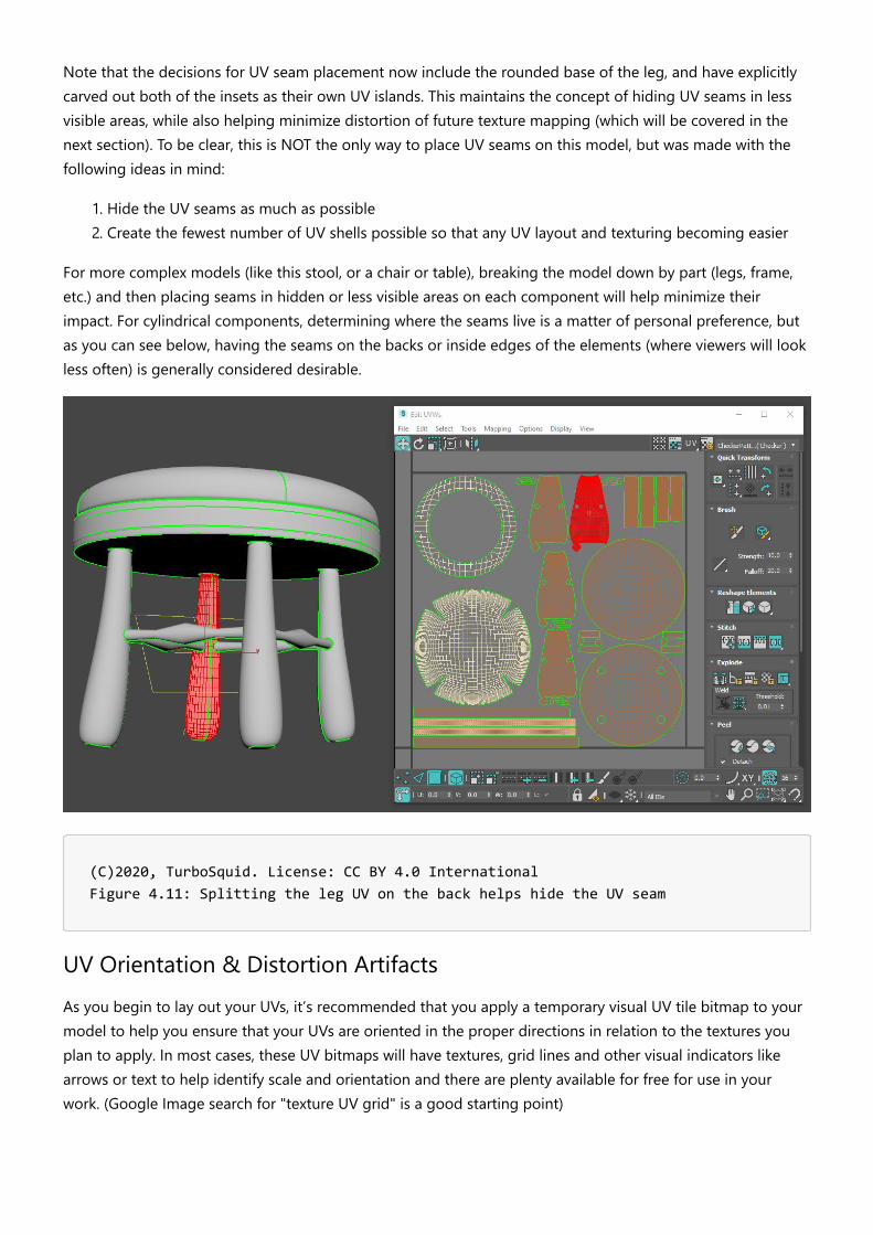
Note that the decisions for UV seam placement now include the rounded base of the leg, and have explicitlycarved out both of the insets as their own UV islands. This maintains the concept of hiding UV seams in lessvisible areas, while also helping minimize distortion of future texture mapping (which will be covered in thenext section). To be clear, this is NOT the only way to place UV seams on this model, but was made with thefollowing ideas in mind:
1. Hide the UV seams as much as possible2. Create the fewest number of UV shells possible so that any UV layout and texturing becoming easier
For more complex models (like this stool, or a chair or table), breaking the model down by part (legs, frame,etc.) and then placing seams in hidden or less visible areas on each component will help minimize theirimpact. For cylindrical components, determining where the seams live is a matter of personal preference, butas you can see below, having the seams on the backs or inside edges of the elements (where viewers will lookless often) is generally considered desirable.
(C)2020, TurboSquid. License: CC BY 4.0 International Figure 4.11: Splitting the leg UV on the back helps hide the UV seam
UV Orientation & Distortion ArtifactsAs you begin to lay out your UVs, it’s recommended that you apply a temporary visual UV tile bitmap to yourmodel to help you ensure that your UVs are oriented in the proper directions in relation to the textures youplan to apply. In most cases, these UV bitmaps will have textures, grid lines and other visual indicators likearrows or text to help identify scale and orientation and there are plenty available for free for use in yourwork. (Google Image search for "texture UV grid" is a good starting point)
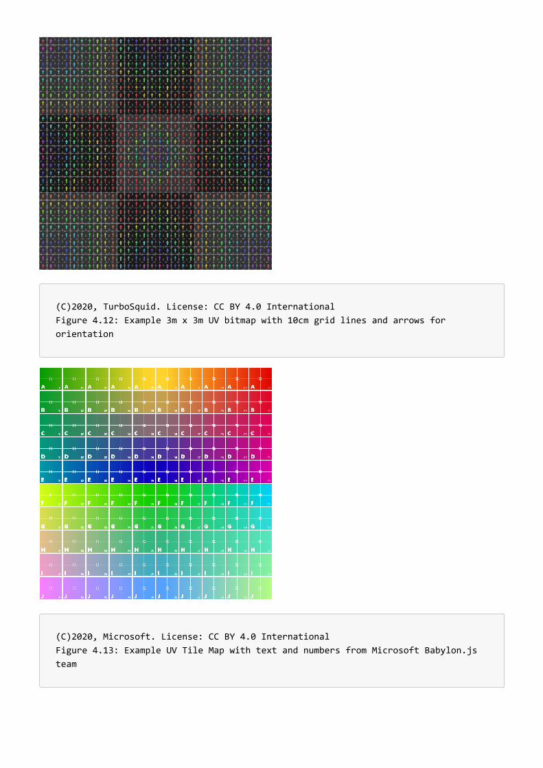
(C)2020, TurboSquid. License: CC BY 4.0 International Figure 4.12: Example 3m x 3m UV bitmap with 10cm grid lines and arrows for orientation
(C)2020, Microsoft. License: CC BY 4.0 International Figure 4.13: Example UV Tile Map with text and numbers from Microsoft Babylon.js team
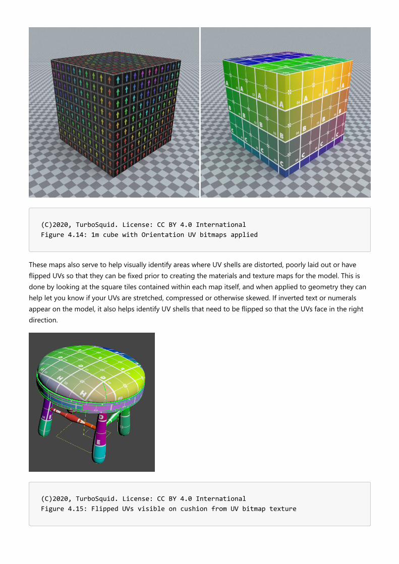
(C)2020, TurboSquid. License: CC BY 4.0 International Figure 4.14: 1m cube with Orientation UV bitmaps applied
These maps also serve to help visually identify areas where UV shells are distorted, poorly laid out or haveflipped UVs so that they can be fixed prior to creating the materials and texture maps for the model. This isdone by looking at the square tiles contained within each map itself, and when applied to geometry they canhelp let you know if your UVs are stretched, compressed or otherwise skewed. If inverted text or numeralsappear on the model, it also helps identify UV shells that need to be flipped so that the UVs face in the rightdirection.
(C)2020, TurboSquid. License: CC BY 4.0 International Figure 4.15: Flipped UVs visible on cushion from UV bitmap texture

When used in concert with UV Seam placement, you can quickly begin to understand how easy or difficultyour model will be to texture as you’re unwrapping it. Consider a pillow and cushion on a sofa.
(C)2020, TurboSquid. License: CC BY 4.0 International Figure 4.16: Good Seam Placement along natural edges of cushions
As you can see from the images above, there is minimal distortion of the UVs (the square grid pattern isn’tdeformed badly or obviously), and it’s visually very easy to understand how the UV layout is oriented inrelation to the model itself. The flow of the arrows in this UV bitmap makes understanding the orientation ofthe UVs self-evident. In these cases, the UV layouts of these two objects match how a fabric might be appliedto a physical version being manufactured.
Moreover, in this case the scale of the UV bitmap gives an indication as to the physical size of the models.Given each grid square in this particular UV bitmap instance represents 0.1 meter in length, an artist can alsovisually tell that the pillow is roughly 0.4 meters wide (roughly 16”), and that the sofa cushion is 0.6 meterswide (roughly 24”).
By contrast, looking at the UV bitmap on bad seam placement and orientation will reveal a host of potentialissues.

(C)2020, TurboSquid. License: CC BY 4.0 International Figure 4.17: Poor Seam Placement (notice the flow and cleanliness of the patterns break)
In examining the images above, the UV layouts for these models ignore natural breaks in the geometry whereseams should exist, and the orientation of the UVs is quite haphazard with the flow and direction going inseemingly random directions. This will make trying to texture these models much more difficult. Additionally,given the intended scale of the UV bitmap applied, the apparent size of the models is completely ignored aswell. The sofa cushion is now 1.1 meters in width (43”) and the pillow is even bigger at roughly 1.5 meterswide (59”). And while real-world scale of textures can be adjusted (and this will be discussed later as part ofusing tileable scanned textures), it is recommended that artists keep scale in mind whenever possible as partof your UV layout process.
Likewise, the UV bitmap can help you readily spot distortion and scaling issues within your mapping layout asyou work. To be clear, minor distortion is sometimes unavoidable (especially on curved and rounded surfaces),but artists should endeavor to minimize any visible stretching or tearing of applied maps as this will make itmuch more difficult to manage the process of creating a final material that does not display the samedistortion artifacts.

(C)2020, TurboSquid. License: CC BY 4.0 International Figure 4.18: Bad UV layout produces visible stretching and tearing on seat cushion
As can be seen above, the UVs of the seat cushion are obviously not clean and produce stretching and tearing(the odd, unexpected warping and smearing as the UV texture map wraps at the top and bottom edges). TheUV texture above also shows the grid as very uneven, with some grid areas looking less square (which is howthey should appear) and more rectangular towards the edges (which indicates poor UV creation). As such, it’simportant to train your eye to spot these sorts of inconsistencies, and when found, to edit the UVs to restorethat even distribution as much as possible.
Many modern UV tools can now show UV distortions as you begin to lay out your UV shells. They do this bygenerally color coding areas of stretching and compression, making the management a much more visual andintuitive process.
Let’s use the stool model above with it’s UVs to review how to identify and deal with the distortion. Visualinspection in 3ds Max immediately shows a number of issues.
1. The UVs on the cushion are heavily distorted along the edges.2. The relative scale of the UVs are quite different as can be seen in the grid pattern size differences
between the various parts of the model (we’ll deal with this problem in another section)3. The flow and direction of the UVs varies in some spots.
Opening the cushion in a UV editor that includes distortion color coding can significantly speed your processup, so this is recommended. Right now, tools like 3ds Max, Maya, UV Layout, and RizomUV are great choices.

(C)2020, TurboSquid. License: CC BY 4.0 International Figure 4.19: UV stretch distortion visualization in 3ds Max, Maya and UV Layout
In 3ds Max, you can activate the visual distortion tools within the Unwrap UVW modifier’s Edit UVWsdropdown window, by selecting the Area Distortion display.
(C)2020, TurboSquid. License: CC BY 4.0 International Figure 4.20
In Maya, you simply activate the UV Distortion display in the UV Editor.
(C)2020, TurboSquid. License: CC BY 4.0 International Figure 4.21
Using the visual indicators, it’s obvious that there is heavy stretching (bright red) on the edges of the cushion.This is due to the original application of a planar map being used to UV map that model. In order to correct

this, we need to come up with another way to split the curved mesh to flatten it out as much as possible sothat the UV texture wraps more predictably around the edges.
In this case, a solution was derived from the edge flow of the polygons along it’s natural seams.
(C)2020, TurboSquid. License: CC BY 4.0 International Figure 4.22: Minimal UV Distortion (pale blue: compression, pale red: stretching)
As can be seen above, the distortion is now reduced significantly with just pale blue and pink tints to indicatesome very minor compression and stretching. The resulting UV bitmap applied looks like this:
(C)2020, TurboSquid. License: CC BY 4.0 International Figure 4.23

Given the new UV layout the UV bitmap tiles are far more even and square in shape, and the distortion issignificantly reduced so that there is no visible stretching or tearing. The tradeoff is that there are four smallseams that need to be hidden by the texture artist, but this should be a relatively straightforward task. Again,it’s important to reiterate that it is nearly impossible to completely eliminate texture distortion on curvedsurfaces like these (or the stool legs), so the goal is to minimize the visible stretching or compression. And tobe clear, this isn’t the only way to UV this element, as there are a number of ways to split the mesh. Justremember to consider that a model may need to be UV’ed in a way that is consistent with the kind of materialbeing applied. Here’s an alternative mapping as an example.
(C)2020, TurboSquid. License: CC BY 4.0 International Figure 4.24: Alternative cushion UV mapping
Another consideration when it comes to distortion of UVs relates to the relative scale of the various UV islandsin your layout. In most cases, the model should contain UVs such that when a UV texture is applied, that eachpiece of the model gets the same amount of visual texture space (often referred to as Texel Density).Consider the poorly UV mapped stool model.
(C)2020, TurboSquid. License: CC BY 4.0 International Figure 4.25: Bad UV Layout for Texel Density

While the UVs are all unwrapped, they have been assembled haphazardly, placed in different orientations andat various scales relative to one another within the UV space. For a component like the legs, the four UV shellsare all different sizes and one is in a different orientation, meaning that each one will get a different amountof texture space and that texturing will be far more difficult than necessary because of the differentorientation of the UV shell.
Most UV technologies have a UV packing system that can help ensure the texel density is consistent. Within3ds Max is the Pack UVs command under the Tools menu in the Unwrap UVW modifier is the starting pointfor ensuring even texture distribution.
(C)2020, TurboSquid. License: CC BY 4.0 International Figure 4.26
Within Maya, using the **Layout **command in the Arrange and Layout rollout of the UV Editor will also helpproduce similar UV packing results.
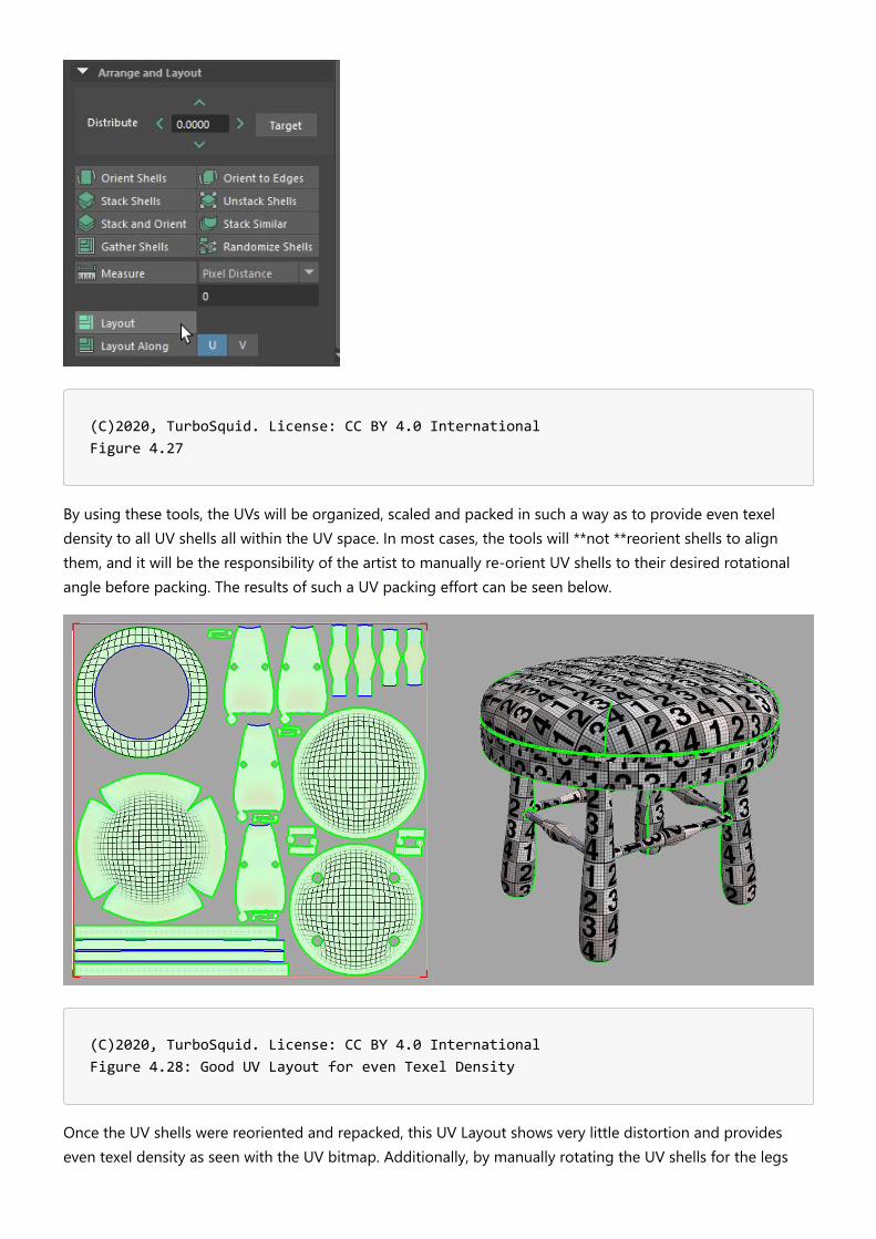
(C)2020, TurboSquid. License: CC BY 4.0 International Figure 4.27
By using these tools, the UVs will be organized, scaled and packed in such a way as to provide even texeldensity to all UV shells all within the UV space. In most cases, the tools will **not **reorient shells to alignthem, and it will be the responsibility of the artist to manually re-orient UV shells to their desired rotationalangle before packing. The results of such a UV packing effort can be seen below.
(C)2020, TurboSquid. License: CC BY 4.0 International Figure 4.28: Good UV Layout for even Texel Density
Once the UV shells were reoriented and repacked, this UV Layout shows very little distortion and provideseven texel density as seen with the UV bitmap. Additionally, by manually rotating the UV shells for the legs

and supports so that they all are oriented in the same direction, the packing tools have left them facing thesame way, which will help with texturing later.
One thing to keep in mind when considering texel density of the various UV shells, is there **are **instanceswhere you might want to provide more texture space to specific parts of your model, and not to other areas.For instance, in the stool above, the wooden seat pan that exists below the cushion does take up a fairamount of texel density in the UV layout even though most or all of it won’t be seen. The same goes for thebottom of the cushion itself. Depending on the configuration of the model (does the stool come without acushion where it would be visible?), the UVs can be further manipulated manually to achieve certain effects.
In an effort to provide more texture space for the cushion UV shell, a good UV artist will continue to work onthe UV layout manually to make the best use of space. In the case of the stool, the two UV shells thatrepresent the wooden seat pan and base of the cushion (denoted in red below) were shrunk down relative tothe rest of the visible model so those elements could be given more texture space.
(C)2020, TurboSquid. License: CC BY 4.0 International Figure 4.29: More optimized UV Layout for Texel Density
If you compare the prior image and this one, you’ll see that the amount of texture space for the cushion andother visible elements has been increased, while not showing any distortions or relative texel densitydifferences. While this practice does not necessarily conform to evenly distributed texel density for the UVs, itcan be used to emphasize or prioritize parts of your model that you want to stand out.
Real world scaleWhen building a model, taking into consideration its scale in the real world is obviously important. Building amodel to real-world scale impacts how the model behaves in a number of essential ways including lighting,physics and placement size in the real world in the case of an Augmented Reality experience. If a model isbuilt at the wrong scale, you’ll get unexpected results. It will also make texturing more difficult due to thescaling differential between what is expected and what occurs when you apply maps to the surface.

Likewise, creating your UV Layouts to reflect real-world scale can be just as important. You want your UVshells to reflect the correct, real-world size of the textures relative to them. In many cases, an artist will beprovided with bitmap textures of scanned or photographed fabrics or materials that have a defined size andrepresent a tileable section of that material. For textures that are easily measurable like fabrics and othertextiles, setting up the UVs to match the proper scale of those textures is important.
Given that several real-time publishing targets use 1 UV unit (0-1 space in both U and V) = 1 meter (glTF andUSDz), it is recommended that you build your UVs with this texture scale in mind. By being consistent here, itwill provide flexibility since real-world scale materials of the same size will immediately appear at the properscale when applied by default.
That does not mean that you have to build your models at meter scale. Smaller objects like clothing or hand-held electronics can still be built in centimeters or inches to get the precision desired (as well as avoidingsome legacy 3D application display issues of modeling at larger unit scales), and only get converted to meterscale upon export. It’s worth noting that both the FBX and glTF exporters have settings to allow scaleconversions. As such, it is **highly **advisable to do tests with conversions to ensure you get the properscaling upon export and within your final delivery format.
With regards to how to think about tileable textures, if you have a measured 10cm x 10cm checker bitmaptexture, and want to apply it to a 5cm x 5cm object, you should only see a quarter of the texture on theoutput model if the UVs are constructed properly. Likewise, if you have a 1m x 1m object, you’ll see the same10cm texture repeat 10 times across the surface.
(C)2020, TurboSquid. License: CC BY 4.0 International Figure 4.30
This tiling texture concept is easy to understand, but only works on certain kinds of UV layouts and has severalconstraints. Since a tiled texture fills the UV space from 0-1 completely, it means UVs must align to it’sorientation and features. As an example, for furniture manufacturers that use specific “cut codes” or patternlayouts in their real-world designs so that the fabrics they use align in a specific way when stitched together,replicating that manufacturing process in 3D requires the UVs to be laid out relative to the tileable fabric

texture itself - and this can often lead to UV shells being forced to live partially outside of the 0-1 UV space oroverlap one another to achieve the proper alignment. While this is perfectly acceptable for many uses (such asoffline rendering for websites or catalog imagery), for real-time applications this kind of UV layout will oftencause problems and should be avoided **unless **the UVs all fit neatly within 0-1 UV space. Moreover, tilingtexture UV layouts don’t support ambient occlusion outputs since UVs are managed in relation to the textureand not to the geometry. As such, generating AO maps becomes impossible for this sort of UV layout.Depending upon the desired publishing target (USDz vs. glTF), this may force some additional work.
A small aside on publishing targets for real time applications and UVs. In most cases, companies will look toleverage as many different output target formats as possible to broaden their availability on AR and web-based e-commerce platforms. As of the middle of 2020, the two biggest formats for this sort of work arecurrently USDz and glTF, and it’s important to understand the constraints each of these put on an artist layingout the UVs with respect to real-world scale.
glTF is more robust and can allow a mixture of tiled texture UVs and atlased UVs as two separate UVchannels. This can be helpful when the main UVs are tiled and use real-world scale UVs that don’tnecessarily fit neatly into 0-1 space, and the second set of UVs is atlased to produce ambient occlusionfor the resulting model. This often has the advantage of allowing the consumer of the model to getvery close to it since the primary UVs are tiled with the maps, while providing high fidelity at a distancewith the AO information as well.USDz, which is Apple’s format to display models for AR experiences via iOS, is more restrictive andcurrently only supports a single UV channel for all of its maps. As such, an artist will have to considerwhether it’s more important to sacrifice the AO information and keep the tiled UVs, or simply atlas all ofthe UVs to accommodate the various maps, including AO through texture baking.
There is no hard and fast rule here as to which approach to take, and it is recommended that companies keepa PBR source model from which they can then derive multiple output targets to accommodate each outputformat. But in some cases, using an atlased UV workflow will be required in order to keep all elements insidethe UV space. Using atlased UVs **also **affords texture artists the ability to apply non-tileable details (such asdistressing or other geometry specific effects) to parts of the model that a tiled texture workflow also can’tsupport.
There are a number of ways to ensure that your atlased UVs are set up to handle real-world scale bitmaptextures.
The most common is to build and pack the UVs into a typical atlas as has been discussed previously, then usethe material and map controls to scale the textures so they represent the proper real-world size of the textureon the existing UVs. At its most basic, this involves creating a reference cube with both the cube and thebitmap texture set up to match its real-world scale, then using that cube as a visual guide in your scene tomatch the bitmap scale as it is applied to the model itself. By adjusting the tiling of the bitmap in relation tothe UV shells, the entire material will be adjusted so that the model and the reference object match in termsof texture scale.
Let’s use the stool model as an example. By default, it’s atlased UV layout is fairly straightforward.

(C)2020, TurboSquid. License: CC BY 4.0 International Figure 4.31: Stool UV Layout
Assume that the following material needs to be applied to the cushion, and that the material has been derivedfrom a scanned fabric swatch that is 10cm x 10cm in length and width.
(C)2020, TurboSquid. License: CC BY 4.0 International Figure 4.32: 10cm x 10cm Ugly fabric texture

By simply creating a material using this map and applying it to the stool cushion, the resulting scale will beway off.
(C)2020, TurboSquid. License: CC BY 4.0 International Figure 4.33: RWS not accurate for cushion
While the cushion itself is roughly 60cm in diameter, this result is due to the fact that the cushion UV shellonly accounts for a small portion of the atlased UV layout, and the tiled texture in the material takes up theentire UV space and represents only 10cm from edge to edge. To make it match properly, create a simplereference cube that represents the actual size of the fabric swatch. In this case, given the texture is 10cm x10cm, the cube created will be built with dimensions of 10cm x 10cm x 10cm.
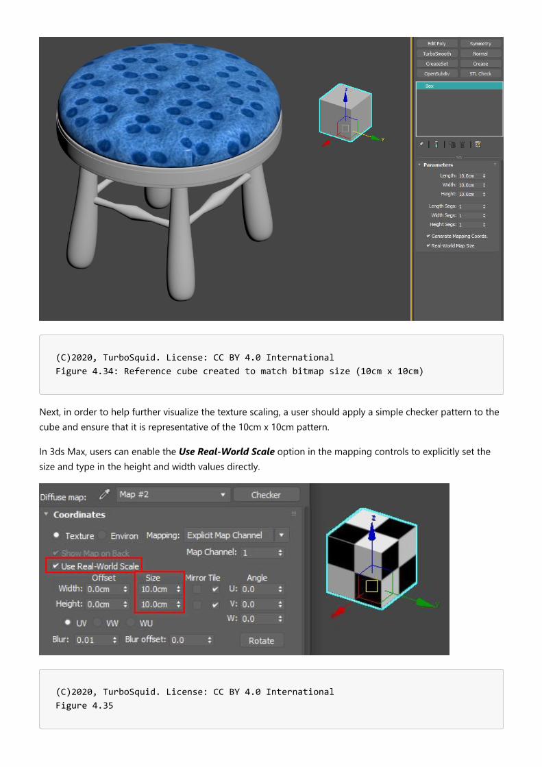
(C)2020, TurboSquid. License: CC BY 4.0 International Figure 4.34: Reference cube created to match bitmap size (10cm x 10cm)
Next, in order to help further visualize the texture scaling, a user should apply a simple checker pattern to thecube and ensure that it is representative of the 10cm x 10cm pattern.
In 3ds Max, users can enable the Use Real-World Scale option in the mapping controls to explicitly set thesize and type in the height and width values directly.
(C)2020, TurboSquid. License: CC BY 4.0 International Figure 4.35

In Maya, simply ensure that the reference cube is the right dimensions and use a bitmap texture with theplace2DTexture node’s Repeat UV settings to 1 and 1 respectively.
(C)2020, TurboSquid. License: CC BY 4.0 International Figure 4.36
With the checker map applied to the reference cube, create a duplicate material for the cushion that alsocontains the checker pattern and apply it to the model. The reason for the duplicate is that you can’t use thereal-world scale option on the model with the bitmap texture given the atlased UV layout. By default, thechecker pattern on the model will be at the wrong scale.
(C)2020, TurboSquid. License: CC BY 4.0 International Figure 4.37: Wrong texture scale
In 3ds max, using the U and V Tiling controls within the bitmap texture, scale the checker pattern to match thereference cube.

(C)2020, TurboSquid. License: CC BY 4.0 International Figure 4.38: UV Tiling match between reference cube and material applied
In Maya, adjust the Repeat UV parameters to match the scale of the reference cube.
Once the tiling has been determined with the checker, simply apply those same tiling values to the originalmaterial’s bitmaps to ensure that they match in scale.
(C)2020, TurboSquid. License: CC BY 4.0 International Figure 4.39: Original material at proper RWS within the UV atlas
Be aware that there are also scripted plug-ins and tools that can automate and help ensure that the tiling ofyour bitmap textures matches the real-world scale of that material via manipulation of the texel densityincluding TexTools for 3ds Max and UV Mapping Toolbox for Maya, among others.
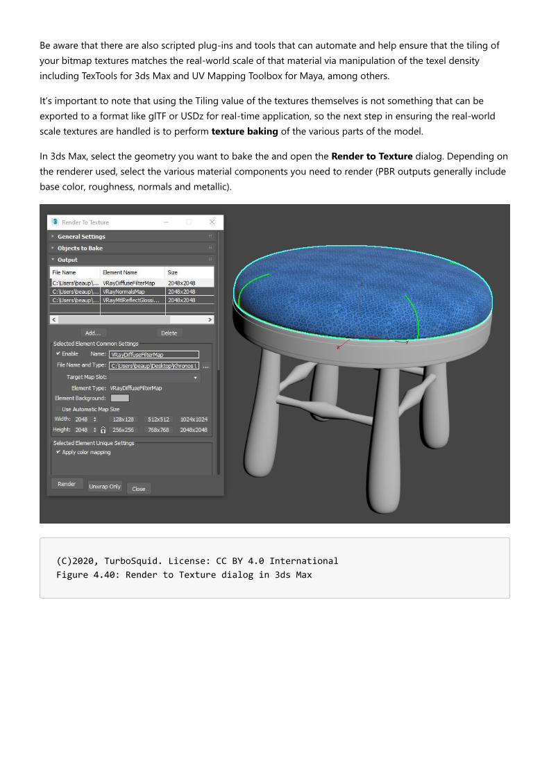
It’s important to note that using the Tiling value of the textures themselves is not something that can beexported to a format like glTF or USDz for real-time application, so the next step in ensuring the real-worldscale textures are handled is to perform texture baking of the various parts of the model.
In 3ds Max, select the geometry you want to bake the and open the Render to Texture dialog. Depending onthe renderer used, select the various material components you need to render (PBR outputs generally includebase color, roughness, normals and metallic).
(C)2020, TurboSquid. License: CC BY 4.0 International Figure 4.40: Render to Texture dialog in 3ds Max
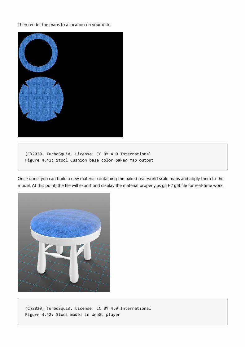
Then render the maps to a location on your disk.
(C)2020, TurboSquid. License: CC BY 4.0 International Figure 4.41: Stool Cushion base color baked map output
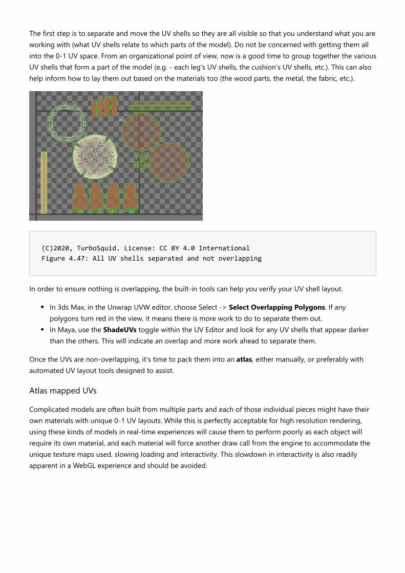
Once done, you can build a new material containing the baked real-world scale maps and apply them to themodel. At this point, the file will export and display the material properly as glTF / glB file for real-time work.
(C)2020, TurboSquid. License: CC BY 4.0 International Figure 4.42: Stool model in WebGL player

Similarly, in Maya, you can use the Transfer Maps tools within the Rendering panel under theLighting/Shading menu to accomplish the same texture baking process.
(C)2020, TurboSquid. License: CC BY 4.0 International Figure 4.43: Maya Transfer Maps location
Now, the most common workflow here is to get all of your real-world scale maps assigned first, then do yourtexture baking so that all of the maps can be combined at the end of the process. This example just showedhow to handle a single element.
The thing to remember is that it’s rarely possible to adjust your UVs to be real-world scale and have them fitwithin the UV 0-1 space. So in those cases, the best alternative is to tile your applied bitmap textures to reflecta real-world scale space so that you get predictable mapping and then bake down the textures from there.
Overlapping UVs Considerations in an Atlas LayoutWithin the UV Mapping layout, you’ll have collections of polygons that are often referred to as UV Islands orUV Shells. These UV shells represent the various parts of your 3D model. As you start to unwrap your model,you might initially focus on separating parts out into obvious groupings before flattening them. For instance,on the stool model, you might separate the model by the legs, the seat, the cushion and so on, then unwrapthose parts into their 2D representations.

(C)2020, TurboSquid. License: CC BY 4.0 International Figure 4.44: Stool model UVs all unwrapped, but only organized by part
As unwrapping proceeds, often, similar UV parts will be laid out identically, (such as all of the legs and supportUV shells in the UV layout above), so there may be a desire to stack these UVs on top of one another to savetime and texture space with the UV layout. This produces overlapping UVs, and while there is nothing wrongwith having them, they can cause some problems depending on how a model’s materials are created, so it’simportant to be aware of them.
Overlapped UVs mean that parts will be forced to share the exact same part of a texture map, so there is noquick way to add unique details to those parts that share the same UVs (including ambient occlusion maps).For some real-time engines, you can also get some weird lighting artifacts from overlapped UVs if that enginedoesn’t automatically generate lightmaps for your model that repack the UVs so that they are non-overlapping.
Note that it is sometimes desirable to overlap UVs in an atlas layout. Repeating elements on a model canpotentially reuse the same exact space in the texture atlas. Overlapping allows the UV shells to be larger,optimizing the texture space and improving the relative texture resolution for each UV shell.

(C)2020, TurboSquid. License: CC BY 4.0 International Figure 4.45: Overlapped UVs in layout highlighted
Ultimately, overlapped UVs must be used cautiously to avoid visual artifacts. If the model uses an ambientocclusion texture, do not reuse texture space for parts that require the occlusion to be different.
Additionally, If a baked model uses overlapping UVs, this will likely cause artifacts to appear in the bakedtexture, since the baker will try to render each UV shell into the same space. Baking tools only capture what isinside the 0-1 UV space; all UV shells outside this space are ignored during baking.
If the decision is made to use overlapping UVs, before baking it's best to move all overlaps outside the 0-1 UVspace. Only one copy of the forward-facing UVs should remain in the 0-1 UV space at baking time. If youmove all overlaps exactly 1 UV unit (any whole number will do), then you can leave them there after the bakeand they will still be mapped correctly.
(C)2020, TurboSquid. License: CC BY 4.0 International Figure 4.46: Overlapping UVs (red) have been moved exactly 1 unit outside the 0-1 UV space.
Whenever possible, it is recommended that you take the time to ensure that none of the UVs overlap. Whilethis can be time-consuming it can help ensure maximum flexibility of your model, regardless of where it isneeded.
As an example, let’s use the stool model and its UV layout above. The goal is to ensure that all of its UV shells(28 total) fit within a single 0-1 UV space. This can be a bit like a puzzle to maximize the space used while notallowing the individual UV shells to overlap.
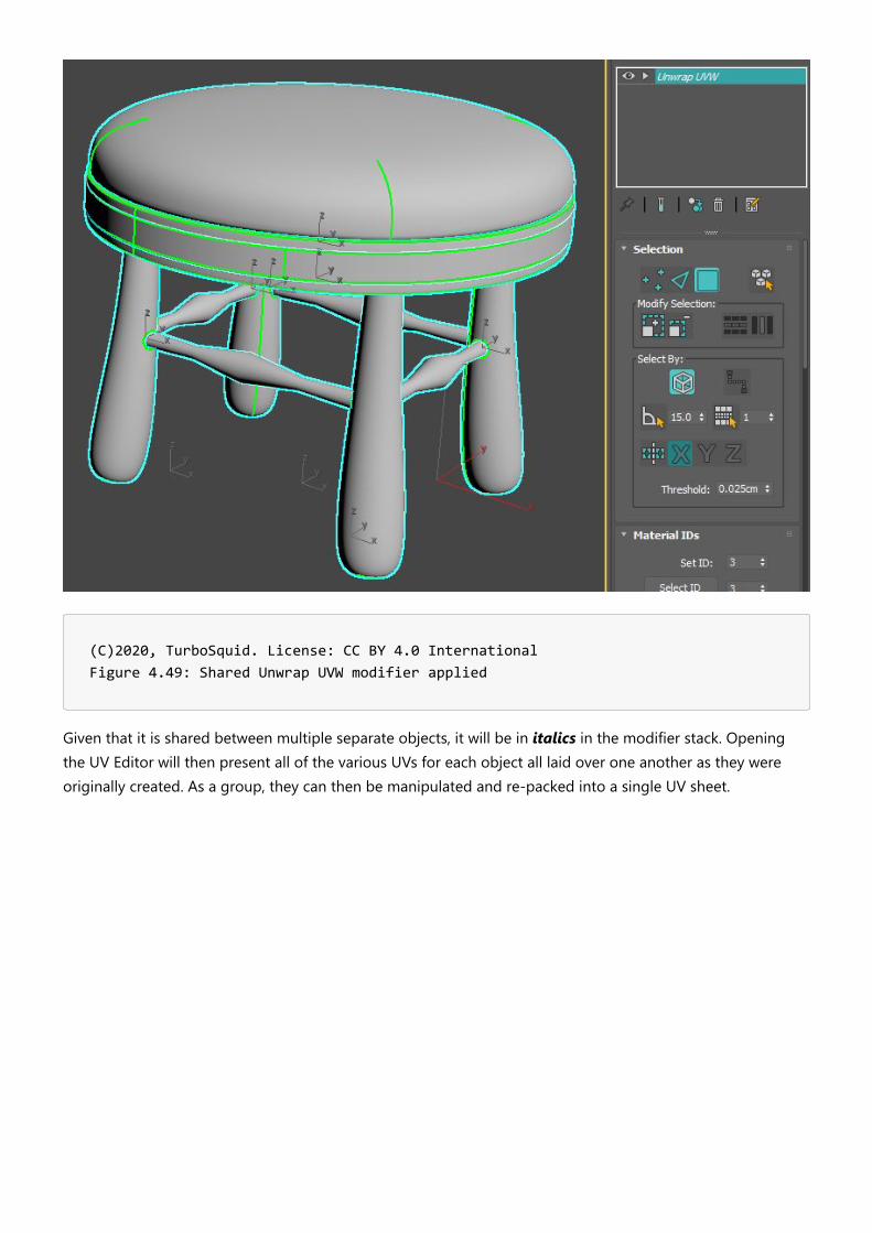
The first step is to separate and move the UV shells so they are all visible so that you understand what you areworking with (what UV shells relate to which parts of the model). Do not be concerned with getting them allinto the 0-1 UV space. From an organizational point of view, now is a good time to group together the variousUV shells that form a part of the model (e.g. - each leg’s UV shells, the cushion’s UV shells, etc.). This can alsohelp inform how to lay them out based on the materials too (the wood parts, the metal, the fabric, etc.).
(C)2020, TurboSquid. License: CC BY 4.0 International Figure 4.47: All UV shells separated and not overlapping
In order to ensure nothing is overlapping, the built-in tools can help you verify your UV shell layout.
In 3ds Max, in the Unwrap UVW editor, choose Select -> Select Overlapping Polygons. If anypolygons turn red in the view, it means there is more work to do to separate them out.In Maya, use the ShadeUVs toggle within the UV Editor and look for any UV shells that appear darkerthan the others. This will indicate an overlap and more work ahead to separate them.
Once the UVs are non-overlapping, it’s time to pack them into an atlas, either manually, or preferably withautomated UV layout tools designed to assist.
Atlas mapped UVs
Complicated models are often built from multiple parts and each of those individual pieces might have theirown materials with unique 0-1 UV layouts. While this is perfectly acceptable for high resolution rendering,using these kinds of models in real-time experiences will cause them to perform poorly as each object willrequire its own material, and each material will force another draw call from the engine to accommodate theunique texture maps used, slowing loading and interactivity. This slowdown in interactivity is also readilyapparent in a WebGL experience and should be avoided.

(C)2020, TurboSquid. License: CC BY 4.0 International Figure 4.48: Unwrapped 0-1 UVs for individual model components
In order to reduce the number of draw calls required to display a model in a real-time environment, youshould optimize your models by combining all of the various UV shells into a single UV Map layout. This isknown as **atlasing **your UVs, and is preferred so that your textures all exist in a single set of bitmaptextures (Base Color, Normal, Roughness, Metalness, AO, etc.) that are applied to the entire model. Instead ofloading multiple materials with multiple maps into a real-time experience, using atlased UVs can combineeverything so that only a single material and set of maps is needed.
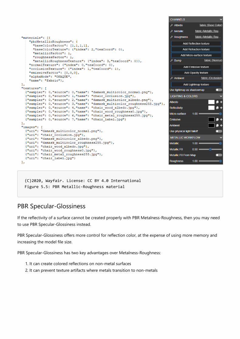
There are several ways to do this in 3ds Max, but the simplest is to select all of the individually UV’edcomponents and apply a new shared **Unwrap UVW **modifier to them all. It does not matter if each modelcomponent has its own Unwrap UVW modifier beneath it as the new UVs will be passed up the modifier stackfrom the existing UVs. The new Unwrap UVW modifier will simply be used to consolidate and re-organize theoriginally created UVs.
(C)2020, TurboSquid. License: CC BY 4.0 International Figure 4.49: Shared Unwrap UVW modifier applied
Given that it is shared between multiple separate objects, it will be in italics in the modifier stack. Openingthe UV Editor will then present all of the various UVs for each object all laid over one another as they wereoriginally created. As a group, they can then be manipulated and re-packed into a single UV sheet.

(C)2020, TurboSquid. License: CC BY 4.0 International Figure 4.50: Shared UV Editor window
At this point, the UVs can be manually edited and repacked, or the artist can simply use one of a number oftools to automatically perform that action.
Selecting Tools -> Pack UVs will yield the results shown below.

(C)2020, TurboSquid. License: CC BY 4.0 International Figure 4.51: Atlased UV layout of stool model
With a shared UV on top of the modifier stack, the benefits for a 3ds Max artist is that the original UVs foreach component is preserved and can be accessed at any time.
In Maya, the process is similar. First, select all of the components of the model.
Next, click on the **Layout **button in the UV Editor window to atlas all of the UV shells into a non-overlapping arrangement.
(C)2020, TurboSquid. License: CC BY 4.0 International Figure 4.52

The only difference is that in Maya, in order to preserve the original UVs for each component, the user willhave to create a new UV texture set before running the Layout command. Otherwise, the changes to each ofthe original components’ UVs in the combined UV layout will be permanent.
The trade-off for atlasing textures is that it reduces the overall texture resolution for your model. If you hadmultiple components in a model that were separately UV mapped with high resolution texture maps, whenyou atlas those textures, you are effectively re-factoring them into a smaller UV space since all of the UVs forthe model now must fit into a single texture map. As such, the resulting resolution of those re-baked texturesis now lower due to the atlasing.
One important note regarding transparent or refractive materials. For parts of a model that containtransparency or refraction, their materials need to remain separate so that they can be applied properly foruse within real time experiences. This does not mean that you can’t atlas the entire model into a single UV set,and simply use the same UVs for a second material. It’s true that doing this adds another draw call to themodel for real-time use, but given that transparency and refraction are handled in a very specific way in real-time engines like Unreal and Unity, having those materials load separately can help avoid other problems thatcan crop up if both transparent and non-transparent materials are combined. And the benefits of using thesame UV layout for the entire model and simply applying two materials to different parts include being ableto repurpose many of the same maps between materials (roughness, metalness, normal, emissive, etc.). Theonly difference is that the base color texture map for a transparent material will have an alpha channel thatwill dictate the transparency blending amount, while the non-transparent material’s base color texture will nothave an alpha channel.
(C)2020, TurboSquid. License: CC BY 4.0 International Figure 4.53: No transparency on Glass (WebGL), left; Transparency on Glass (WebGL), right

(C)2020, TurboSquid. License: CC BY 4.0 International Figure 4.54: UVs for entire Call Box model
(C)2020, TurboSquid. License: CC BY 4.0 International Figure 4.55: Alpha channel of Glass Material
Another exception is for models which need to display variants for interactive configurability. When a modelhas material variations such as a shoe with different colored laces, uppers, soles, etc. then each of these partswill need their own materials. Then the customer will be able to swap materials on individual parts toconfigure their custom product. Each part can then use an atlas UV layout and a unique material. So atlasingthe UVs in situations like this would be limited to UVs associated with specific material groupings.

UV SetsglTF spec allows multiple UV sets. However some viewers support multiple UV sets while others do not.USD does support UV sets if using _usdExport _command flag -uvs.**USDZ **currently does not support multiple UV sets on AR Quick Look.
KHR extensionsKHR_texture_transform is not required to support tiling, you can simply scale the UVs themselves. It isrequired however if you wish to use Real-World Scale UVs, and tile each bitmap independently in the material.
Materials & TexturesVersion 1.0.0Last Updated: October 20, 2020
Materials are used to add visual details and shading to the flat surfaces of a 3D model. They help definewhether the surface looks like wood, fabric, metal, plastic, glass, etc.
The same material can be reused on as many models as you wish. A furniture supplier may use the same darkoak wood stain for a line of home furnishings; the look of this surface can be defined in a single material thatis reused on all their 3D models. This creates a consistent look, and reduces rework.
(C)2020, Wayfair. License: CC BY 4.0 International Figure 5.1: A model with a default material

(C)2020, Wayfair. License: CC BY 4.0 International Figure 5.2: The same model with customized materials
Material TypesThere are a few material types to use for real-time 3D models in e-commerce applications.
PBR Metallic-RoughnessPBR Specular-GlossinessDiffuse-SpecularUnlitCustom shaders
PBR MaterialsPBR stands for Physically Based Rendering. PBR is an approach for materials and rendering that createsaccurate and predictable results in varying lighting conditions (sunlight, indoor lighting, night time, etc).

(C)2016, [theblueturtle_](https://sketchfab.com/theblueturtle_). License: CC BY 4.0 International Figure 5.3: Battle Damaged Sci-fi Helmet - PBR. glTF demo: https://www.babylonjs.com/demos/pbrglossy/
(C)2016, [theblueturtle_](https://sketchfab.com/theblueturtle_). License: CC BY 4.0 International Figure 5.4: PBR textures (from left): Base Color, Occlusion, Roughness, Metalness, Normal, Emissive
PBR Metalness-RoughnessFor most surfaces we recommend using a PBR Metalness-Roughness material.
It allows a wide range of surface types, is easy to use and understand, keeps file sizes smaller for downloads,and uses less memory when rendering.
(C)2020, Wayfair. License: CC BY 4.0 International Figure 5.5: PBR Metallic-Roughness material
PBR Specular-GlossinessIf the reflectivity of a surface cannot be created properly with PBR Metalness-Roughness, then you may needto use PBR Specular-Glossiness instead.
PBR Specular-Glossiness offers more control for reflection color, at the expense of using more memory andincreasing the model file size.
PBR Specular-Glossiness has two key advantages over Metalness-Roughness:
1. It can create colored reflections on non-metal surfaces2. It can prevent texture artifacts where metals transition to non-metals

(C)2020, Wayfair. License: CC BY 4.0 International Figure 5.6: Satin fabric is a non-metallic surface that relies on colored reflections. Without colored reflection (left), versus with colored reflection
Image by Microsoft, based on the Water Bottle sample model. License: Public Domain Figure 5.7: The PBR Metalness-Roughness material can cause fringing artifacts between metals and non-metals. On the left, the edges of the red label show fringe artifacts between the red paint and the brass metal. On the right, the PBR Specular-Glossiness material doesn’t show these errors

(C)2020, Joe Wilson. License: CC BY 4.0 International Figure 5.8: Another example of transition artifacts caused by a Metalness texture
Diffuse-Specular MaterialThis is an older non-PBR material type, in common use before PBR workflows became commonplace. If anasset uses this material type, we recommend to convert the material into a PBR Metalness Roughnessmaterial.

Image by Microsoft, based on the Boom Box sample model. License: Public Domain Figure 5.9: Diffuse-Specular (left), versus PBR Metalness-Roughness. Model by Microsoft, Diffuse-Specular conversion by Gary Hsu.
Diffuse-Specular does not use accurate lighting, so the common workflow was to paint lighting and shadinginformation into the Diffuse texture. Baked-in lighting can give surfaces more depth, at the expense of lookingincorrect when the model is loaded in scenes with different lighting.
When using a PBR material, ambient occlusion is kept separate from the Base Color texture, so it can beapplied only to soft diffuse lighting but not to dynamic lighting. This gives a more realistic result. Diffuse-Specular lacks this separation, so ambient occlusion is often painted into the Diffuse texture which can cause a“dirty” looking surface.
(C)2020, Wayfair. License: CC BY 4.0 International Figure 5.10: Textures with shading can cause the model to look dirty (left). PBR models should use un-shaded textures (right)
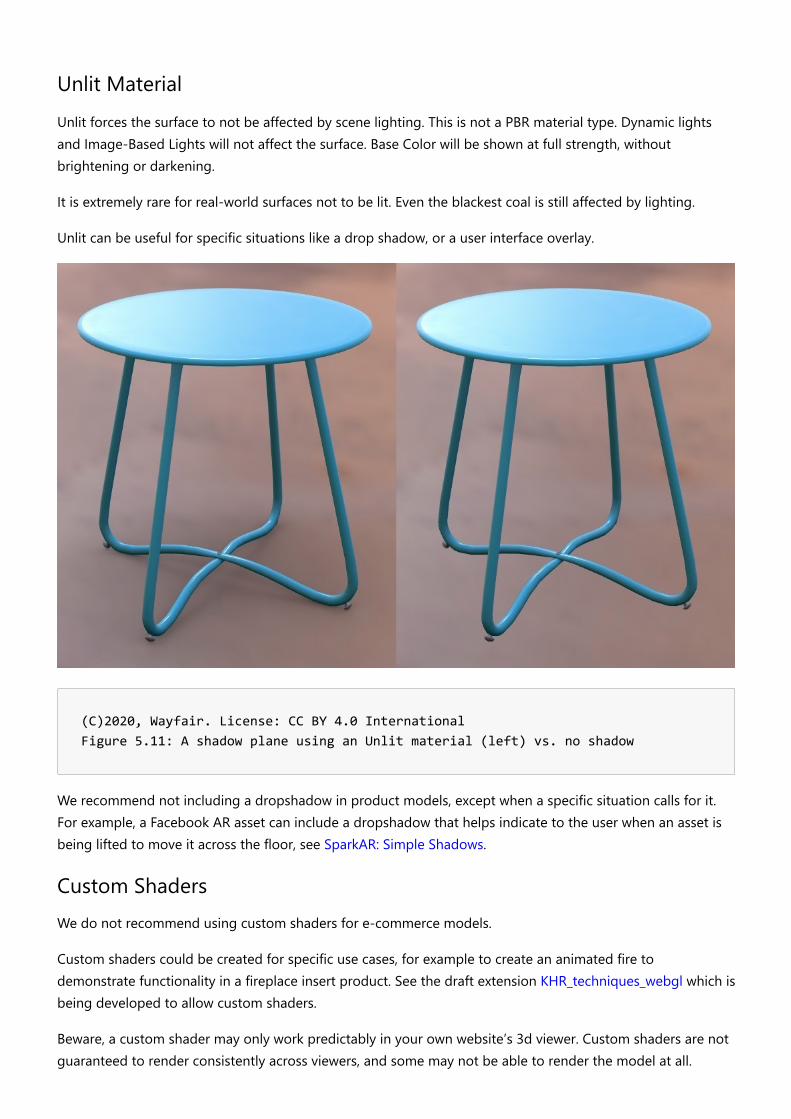
Unlit MaterialUnlit forces the surface to not be affected by scene lighting. This is not a PBR material type. Dynamic lightsand Image-Based Lights will not affect the surface. Base Color will be shown at full strength, withoutbrightening or darkening.
It is extremely rare for real-world surfaces not to be lit. Even the blackest coal is still affected by lighting.
Unlit can be useful for specific situations like a drop shadow, or a user interface overlay.
(C)2020, Wayfair. License: CC BY 4.0 International Figure 5.11: A shadow plane using an Unlit material (left) vs. no shadow
We recommend not including a dropshadow in product models, except when a specific situation calls for it.For example, a Facebook AR asset can include a dropshadow that helps indicate to the user when an asset isbeing lifted to move it across the floor, see SparkAR: Simple Shadows.
Custom ShadersWe do not recommend using custom shaders for e-commerce models.
Custom shaders could be created for specific use cases, for example to create an animated fire todemonstrate functionality in a fireplace insert product. See the draft extension KHR_techniques_webgl which isbeing developed to allow custom shaders.
Beware, a custom shader may only work predictably in your own website’s 3d viewer. Custom shaders are notguaranteed to render consistently across viewers, and some may not be able to render the model at all.

Search engines or advertisers may fail to render the custom shader, preventing your product from beingdiscoverable.
If a custom shader must be used, we recommend you create another LOD (Level of Detail model) with astandard PBR Metalness-Roughness material, so the model can be reliably rendered by other viewers.
Multiple Materials per ModelAn asset can either use a single material for the whole model, or else multiple materials can be assigned todifferent parts of the model. There are tradeoffs between the two approaches.
Single Material
It is recommended in most cases to use a single material for the entire asset. This reduces the file size, andimproves rendering performance.
When an asset has multiple surface types, for example cloth and wood and metal, then a single material willrequire all textures to be combined into a UV “atlas” layout.
(C)2020, Wayfair. License: CC BY 4.0 International Figure 5.12: UV atlas layout

Multiple Materials
While it is generally recommended to use a single material, a model can use multiple materials instead whenneeded.
There are two common reasons to use multiple materials:
1. Tiled textures2. Material variants
Multiple Materials - Tiled Textures
If blurriness is a concern, then tiled textures can be used. Each tiling texture will need its own material. Forexample, a chair with wood, metal, and fabric could use three separate materials.
Note however that real-time rendering performance can be slower with multiple materials because this canincrease draw calls.
(C)2020, Wayfair. License: CC BY 4.0 International Figure 5.13a: A real-time model with four materials
(C)2020, Wayfair. License: CC BY 4.0 International Figure 5.13b: The material assignments shown as colors. Red pieces use the fabric material, green uses wood, blue uses metal, and yellow uses the label material
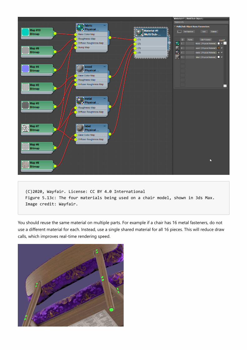
(C)2020, Wayfair. License: CC BY 4.0 International Figure 5.13c: The four materials being used on a chair model, shown in 3ds Max. Image credit: Wayfair.
You should reuse the same material on multiple parts. For example if a chair has 16 metal fasteners, do notuse a different material for each. Instead, use a single shared material for all 16 pieces. This will reduce drawcalls, which improves real-time rendering speed.
(C)2020, Wayfair. License: CC BY 4.0 International Figure 5. : The same metal material is reused on multiple parts (green highlight for emphasis)
Multiple Materials - Material Variants
Multiple materials will also allow the use of the Base Color Factor in a material. This can be used alone forsolid-colored surfaces such as simple plastic, or it can colorize a grayscale Base Color texture such as a fabricweave. The color value can be swapped to represent surface variants, while using very small filesizes.

(C)2020, Wayfair. License: CC BY 4.0 International Figure 5.16: Material variants using baseColorFactor to colorize a texture
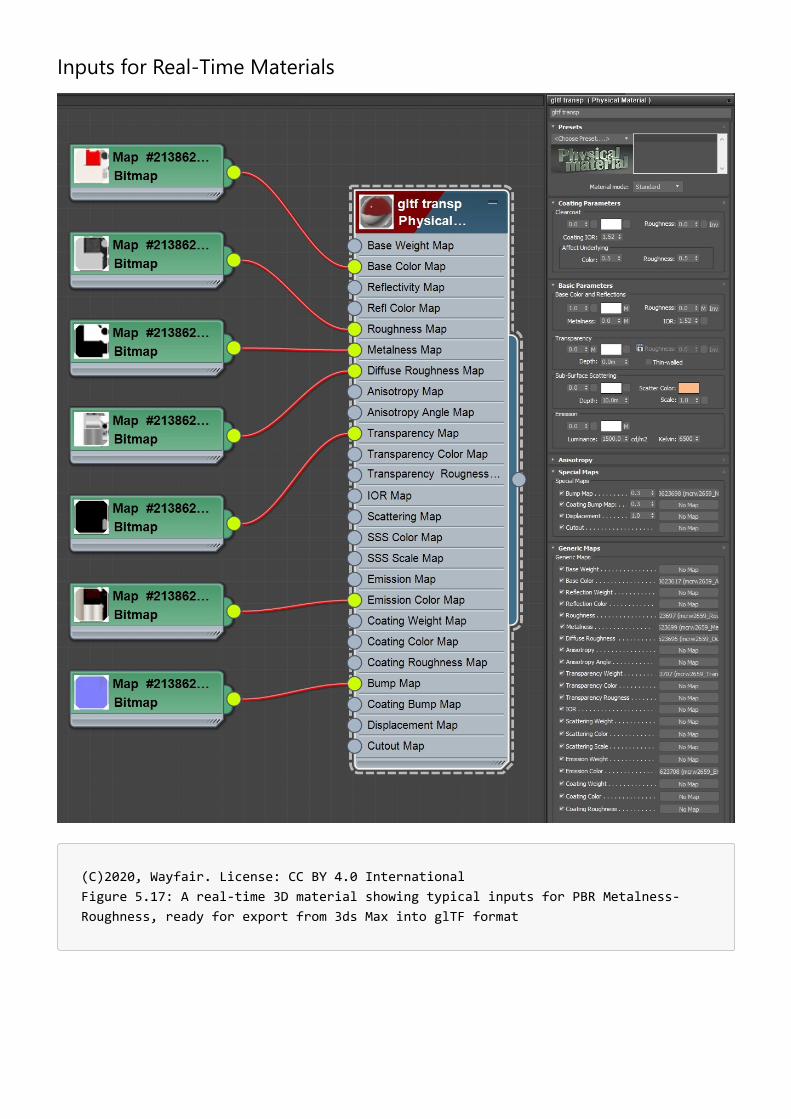
Inputs for Real-Time Materials
(C)2020, Wayfair. License: CC BY 4.0 International Figure 5.17: A real-time 3D material showing typical inputs for PBR Metalness-Roughness, ready for export from 3ds Max into glTF format

(C)2020, Wayfair. License: CC BY 4.0 International Figure 5.18: A complex material for non-real-time rendering in V-Ray, in 3ds Max
Complex materials cannot be used for real-time 3D models. Non-realtime renderers like Arnold or V-Ray allowcomplex material setups with unlimited material compositing. These layers are typically too slow to render atinteractive speeds.
Real-time materials must be simple to allow fast interactive rendering. Use simple bitmap textures or valuesinstead of complex layering and compositing.
Textures for PBR Metalness-RoughnessThere are seven texture inputs available in a PBR Metalness-Roughness material.
In alphabetical order:
1. Alpha Coverage2. Base Color3. Normal4. Emissive5. Metalness6. Occlusion7. Roughness
None of these are required; use only the textures you need. This reduces file size, which can improvedownload time and save memory.
Each input can be a single numerical value instead of a texture. Whenever possible it’s better to use valuesinstead of textures to make the model file smaller. However when the input type needs variation across thesurface of the model, then a texture is worth using.
Material Workflow OrderThe textures for Metalness-Roughness materials can be created in any order. However we suggested applyingyour texturing decisions in this order for best results:
1. Alpha CoverageSurfaces with Alpha Coverage should be kept separate from opaque surfaces, for betterrendering performance and less depth sorting artifacts.
2. MetalnessMetalness has a direct correlation with Base Color, which is handled differently for metals vs.non-metals. It is best to decide the values for Metalness before working on the Base Color.
3. Base ColorThe base color of the surface has one of the largest impacts on the visual result. If the surface ismetal, Base Color stores the reflection color (gold, copper, brass, etc.). For non-metal surfacesBase Color controls traditional non-reflective surface detail (wood grain, brick color, fabric prints,etc.).
4. RoughnessRoughness has a large impact on the photo-realism of a surface.Roughness defines the micro-surface (small) bumpiness, which essentially controls how blurry or sharp reflections will be.
5. Normal.The Normal bump texture is used for macro-surface (large) bumpiness. Normal adds variation insurface direction to simulate grooves, pits, fibers, etc. Normal can be used to store the curvaturefrom a higher-detail model, allowing a lower-resolution model to look like it has moresmoothness or detail.
6. EmissiveAn Emissive can be used for internal lighting, glow-in-the-dark paint, LED displays, etc. For bestresults, use a ray traced renderer to precalculate emissive light bounces and store this in an

Emissive texture. This is best accomplished when the model and material are near completion, soall the details can affect the emissive calculations.
7. OcclusionAmbient occlusion is used for soft shadows wherever model intersections and crevices occur. Forbest results, use a ray traced renderer to precalculate occlusion and store this in an Occlusiontexture. This is best accomplished when the model and material are near completion, so all thedetails can affect the occlusion calculations.
PBR Colors and ValuesHigh quality PBR relies on physically-based material values, measured from real-world materials.
Most textures and colors for Base Color should be within the PBR “safe color” range to ensure the assetrenders well in the widest possible array of lighting environments. These are guidelines though, some rarematerials may require using values outside the safe color range, Vantablack for example can be darker.
The color values for Base Color should be within the range of 30 to 243. A value of 30 can be used for thedarkest material (such as coal or black paint). 243 can be used for pure snow. Most surfaces should use aconsiderably smaller color range, see the charts below.
Most art software uses the 8-bit color range to specify color values, which goes from 0 to 255. However linearcolor values may be used if working with higher bit depths.
Base Color and Emissive textures should be authored in sRGB color space, which is analogous to 1.22 gamma.These textures are commonly derived from photography, and cameras nearly always apply gamma to theirimages. All other textures (Alpha Coverage, Metalness, Roughness, Normal, Occlusion) should be authored inLinear color space.

Base Color for Non-Metals (Dielectrics)
Content creators can use these color values as a starting point, adjusting as needed to match their real-worldreferences. Most art programs use sRGB colors, however Linear colors are also provided as some tools mayrequire colors to be specified in Linear color space.
sRGB Value Linear Value sRGB swatch
Charcoal (30, 30, 30) (0.009, 0.009, 0.009)
Fresh asphalt (50, 50, 50) (0.028, 0.028, 0.028)
Black acrylic paint (56, 56, 56) (0.036, 0.036, 0.036)
Worn asphalt (91, 91, 91) (0.104, 0.104, 0.104)
Bare soil (85, 61, 49) (0.089, 0.043, 0.027)
Green grass (123, 130, 48) (0.201, 0.227, 0.074)
Desert sand (177, 167, 132) (0.448, 0.394, 0.235)
Fresh concrete (185, 181, 175) (0.494, 0.476, 0.437)
Ocean Ice (187, 191, 192) (0.536, 0.529, 0.505)
White acrylic paint (227, 227, 227) (0.767, 0.767, 0.767)
Fresh snow (243, 243, 243) (0.899, 0.899, 0.899)

Base Color for Metals (Conductors)
sRGB Value Linear Value sRGB swatch
Iron (196, 199, 199) (0.560, 0.570, 0.580)
Silver (252, 250, 245) (0.972, 0.960, 0.915)
Aluminum (245, 246, 246) (0.913, 0.921, 0.925)
Gold (255, 226, 155) (1.000, 0.766, 0.336)
Copper (250, 208, 192) (0.955, 0.637, 0.538)
Nickel (211, 203, 190) (0.660, 0.609, 0.526)
Titanium (193, 186, 177) (0.542, 0.497, 0.449)
Cobalt (211, 210, 207) (0.662, 0.655, 0.634)
Platinum (213, 208, 200) (0.672, 0.637, 0.585)
Base Color - PBR Safe Colors
Each pixel luminance value should be calculated by either 1) averaging the R, G, and B channels, and dividingby 3, OR 2) combined at a weight of 0.299R, 0.587G and 0.114B and divided by 3 (this is the AllegorithmicSubstance method which is optimized for producing deep blues and reds).
The resulting pixel value should be within the PBR acceptable value range (the group needs to close on whatthis is: Substance validator “red zone”: 30-243 sRBG, Substance validator “orange zone” 50-225sRGB, 2D videosRGB acceptable range 16-235 sRGB, etc.).
In a render any pixel value outside of this determined range would be a result of the texture base color and itsinteraction with light or shadow (so for example if a pixel showed up as 255 it would be the result of lightinteracting with a base color pixel valued at 243 or less and not because the base color pixel itself was 255.
PBR Safe Color References:
https://academy.substance3d.com/courses/the-pbr-guide-part-2https://blogs.unity3d.com/2015/02/18/working-with-physically-based-shading-a-practical-approach/https://docs.unity3d.com/uploads/ExpertGuides/Dark_Dielectric_Materials.pdfhttps://docs.unrealengine.com/en-US/Engine/Rendering/Materials/PhysicallyBased/index.htmlhttps://www.fxguide.com/fxfeatured/game-environments-parta-remember-me-rendering/https://marmoset.co/posts/physically-based-rendering-and-you-can-too/https://seblagarde.wordpress.com/2014/04/14/dontnod-physically-based-rendering-chart-for-unreal-engine-4/
Alpha Coverage TextureAlpha Coverage in glTF currently allows two techniques “alpha blending” and “alpha test”.
Transparency in real-world materials like glass, acrylic, and water is fundamentally different from how AlphaCoverage works in glTF. Real-world transparent surfaces often both reflect and transmit light. Completely clearglass transmits light from behind it, but it is also very reflective. Alpha Coverage does not represent thiscorrectly, it simply controls the visibility of the surface, it dims all surface characteristics at once.
Alpha Coverage should be limited to “cutout” style material effects, such as a leaf texture applied to a quadmodel. However in practice we must be able to represent semi-transparent materials like glass or water, so weuse partial Alpha values like 30% gray.
Partial alpha allows the Base Color and reflections to be partially seen, for a rough approximation of clearsurfaces. This is better than no glass at all, but is not physically correct and thus does not produce accurateresults.
By the end of 2020, improvements in material technology will add better support for partially-transparentsurfaces. The upcoming extensions for thin-surface transmission (KHR_materials_transmission) and volumetransmission (KHR_materials_volume) will allow for better transparency control and behavior.
Alpha Coverage Methods
There are two basic methods for controlling how Alpha Coverage is rendered in glTF materials.
Alpha Blend
This includes materials where the transparency is due to holes in the material so little or no absorption,refractive, or reflective properties are needed. e.g. gauze or burlap with visible gaps between the threadsbasically behave this way.
This type of transparency is included in the current glTF 2.0 specification as the alpha channel of thebaseColor texture parameter.
Alpha Test
This type of transparency is used for materials that are either fully transparent or fully opaque, with a hardedge between the two. Also known as Masked, Screendoor, or Cutout.
Typically, a black-and-white texture is used to identify where the material should and shouldn’t be rendered.Note that the texture should have antialiasing between black and white, otherwise stair-stepping artifacts willbe more apparent along the edges.
As no blending is required, this method exhibits no render-order or blend-complexity issues like Alpha Blend.
Alpha Coverage Values
Alpha Coverage textures use white as completely solid, with grays for levels of partial visibility, and black ascompletely see-through.

Alpha Coverage can also use a single value for the whole material, anywhere between 0 for clear and 1 forsolid.
Alpha Coverage in USDz
USDz uses the same convention as glTF. For USDz white is solid, black is clear.
Alpha Coverage Should be Used Sparingly
Avoid enabling Alpha Coverage if a material has no transparency, for example using a white texture or a 1.0value to create opaque parts. Alpha Coverage is more expensive to render in real-time, even when completelyopaque, so it should be removed when not needed. Alpha Coverage surfaces also use a different renderingmethod that can cause depth artifacts, which can cause far surfaces to render in front of near surfaces.
Alpha Coverage materials should be kept separate from opaque ones. We suggest splitting models intoseparate parts, so Alpha Coverage surfaces can be rendered separately.
Multiple Alpha Coverage surfaces within the same model should also be split into separate parts. Thisimproves rendering by allowing the real-time renderer to render them in order, from back to front. Forexample if you have a light fixture with a row of five lightbulbs, the glass for each bulb should be a separatepart within the overall model. You can reuse the same glass material on all the bulbs, but each bulb should stillbe a separate part, movable independently from the other bulbs. Workflow : separating transparent fromopaque materials
The total number of separate parts in the average product model should be as few as possible. Only separatethe parts that need to be interacted with, for example doors on a cabinet.
Alpha Coverage Errors
The biggest concern when creating assets with Alpha Coverage is the complexity of rendering triangles in thecorrect order. Asset creators should not assume perfect depth sorting as most real-time renderers are not ableto support this.
Most renderers will sort on a per-mesh basis and usually render from furthest to closest. Intersecting oroverlapping transparent meshes may exhibit rendering problems and should be avoided if possible.
A less common technique is to rely on triangle-ordering to ensure that transparent triangles render last.Triangles affected by transparency are specifically placed at the end of the rendering process to ensure thatthey render after all opaque triangles.

(C)2020, Wayfair. License: CC BY 4.0 International Figure 5.19: A model using Alpha Coverage for the fine wicker detail
(C)2020, Wayfair. License: CC BY 4.0 International Figure 5.20: A closeup showing depth sorting errors (left) versus correct depth sorting (right)
Real-time renderers use different methods to solve depth sorting with Alpha Blended surfaces, so differentfixes may be needed.
Alpha Coverage - Fix Method 1
The most common fix is to detach each Alpha Coverage surface as a separate model. In the wicker example,the triangles that represent the inside squiggly wicker surface would be one model, the triangles for theoutside part of the squiggly wicker would be another model, and all the whole rest of the asset (the partswithout Alpha Coverage) would be another model.

(C)2020, Wayfair. License: CC BY 4.0 International Figure 5.21: To solve depth sorting errors, Alpha Coverage surfaces can be detached into separate models: inside (red), and outside (green). The rest of the model without Alpha Coverage is shown in blue
Alpha Coverage - Fix Method 2
If errors still appear after detaching the surfaces into separate models, another common fix method is tomanually change the order that surfaces will be rendered. Detach the mesh elements, and re-attach them inthe order you want them to be drawn. In the wicker example, the outside of the basket should always berendered after the inside; the inside is never seen overtop the outside. To solve this, detach the inside andoutside parts, then attach them in rendering order: inside first, then outside after.
Alpha Coverage - Fix Method 3
A third fix method is to use Alpha Test instead of Alpha Blend. Alpha Test never has depth sorting errorsbecause there is no blending; pixels are either on or off. This may not work in all situations however, sinceAlpha Test does not offer partial transparency like what’s needed for glass or liquids.

Alpha Coverage and Backface Culling
A glTF material can disable backface culling. This causes a single-sided surface to render as two-sided. This isan easy way to reuse the same surface on the front and back of a model. It also reduces the number ofvertices on the model, which can reduce the file size.
Unfortunately, if Alpha Blending is being used, disabling backface culling can cause depth sorting errors. Thefront and rear surfaces will be in the same model, which often causes depth sorting artifacts. If this occurs it isbetter to manually duplicate and flip the front triangles, creating a separate model for the rear triangles, thenenable backface culling.
(C)2020, Wayfair. License: CC BY 4.0 International Figure 5.22: From left: wicker chair with backface culling enabled, backface culling disabled, enabled on the green part, disabled
Base Color TextureThe color and texture of the surface has one of the largest impacts on the visual result.
The Base Color controls the colors you see when a surface is evenly lit, without reflection in the way.
When using a PBR Metal/Rough material, the Base Color stores the color of the reflections for metals (gold,copper, brass, etc.). When the surface is non-metal, Base Color is used for traditional non-reflective diffusetexture (wood, brick, fabric, etc.).

(C)2020, Wayfair. License: CC BY 4.0 International Figure 5.23: The Base Color texture should have no lighting information. Lighting and shading in PBR is provided by the scene
If the surface uses Alpha Coverage, it will be stored the alpha channel of the Base Color texture. This is anoptimization to reduce the number of separate texture files that need to be sampled into memory at runtime.
(C)2020, Wayfair. License: CC BY 4.0 International Figure 5.24: Base Color and Alpha Coverage are combined together into a single texture
Depending on the exporter you use, the Base Color and Alpha Coverage may be created as separate textures,which the exporter will combine during export. If it does not, you may need to manually put the AlphaCoverage into the alpha channel of the Base Color.
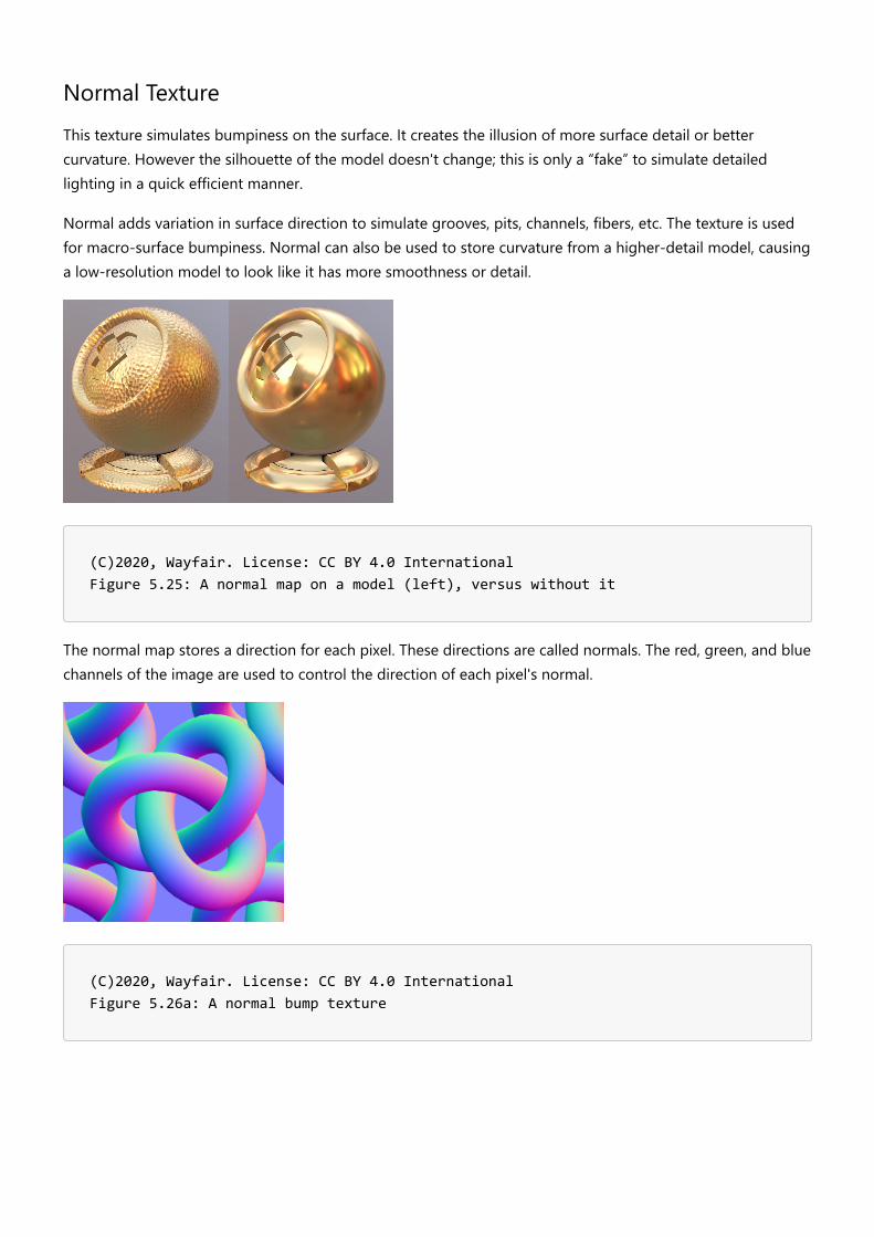
Normal TextureThis texture simulates bumpiness on the surface. It creates the illusion of more surface detail or bettercurvature. However the silhouette of the model doesn't change; this is only a “fake” to simulate detailedlighting in a quick efficient manner.
Normal adds variation in surface direction to simulate grooves, pits, channels, fibers, etc. The texture is usedfor macro-surface bumpiness. Normal can also be used to store curvature from a higher-detail model, causinga low-resolution model to look like it has more smoothness or detail.
(C)2020, Wayfair. License: CC BY 4.0 International Figure 5.25: A normal map on a model (left), versus without it
The normal map stores a direction for each pixel. These directions are called normals. The red, green, and bluechannels of the image are used to control the direction of each pixel's normal.
(C)2020, Wayfair. License: CC BY 4.0 International Figure 5.26a: A normal bump texture

(C)2020, Wayfair. License: CC BY 4.0 International Figure 5.26b: The red channel stores the left-right directions of the pixels
(C)2020, Wayfair. License: CC BY 4.0 International Figure 5.26c: The green channel stores the up-down directions of the pixels
(C)2020, Wayfair. License: CC BY 4.0 International Figure 5.26d: The blue channel stores the in-out directions of the pixels

Normal - Converted vs. Baked
A Normal texture can be generated using two basic methods: converting a grayscale texture or photo, versusbaking it from a model.
We recommend using converted textures in most cases, since these can be generated easily from scannedswatches, can be easily tiled to create high resolution materials that look good in closeups, and can be reusedon more than one model.
A converted Normal map is useful for homogenous repetitive surfaces, for example wood grain or fabricweave or terracotta tiles. It can be repeated across the model to create high-resolution shading details, andcan be reused by multiple models. It cannot however reproduce unique location-specific details, like wornedges or non-repeated surface features.
A baked Normal map can be used to transfer the surface details from a high-resolution model onto a lower-resolution model. Each pixel of the Normal map captures the surface slope of the original high-resolutionmodel, so the unique shapes are replicated in the final model. The resolution is limited however because anatlas covers the whole model so it tends to be blurry in closeups. Atlas textures also cannot be reused ondifferent models, the layout is specifically tied to the low-resolution model it was created for.
(C)2020, Eric Chadwick. License: CC BY 4.0 International Figure 5.27: From left, a baked Normal applied to a low-resolution model, the same model without Normal, and the Normal texture displayed in full-bright mode
Emissive TextureEmissive simulates glow or self-illumination. Emissive can be used for internal lighting, glow-in-the-dark paint,LED displays, neon, etc.
Parts of the surface can be made to glow, as if lit internally. Emissive usually does not cast light onto othersurfaces, it only makes the current surface appear to glow. Emissive is not affected by lighting, it is shown full-bright on the model. Emissive is additive, black causes no change.
For best results, use a ray traced renderer to precalculate bounced lighting and store this in an emissivetexture. This is best added when the model and material are near completion, so model details can affect theemissive calculations.

(C)2020, Wayfair. License: CC BY 4.0 International Figure 5.28: A model with and without an emissive texture. This model uses emissive to simulate the lamp shade being illuminated by the light bulb
Metalness TextureThe Metalness texture controls which parts of a surface are considered metallic or not.
Metallic surfaces reflect light very differently from non-metals. Metalness has a large effect on the final colorand reflectivity of the surface, as well as informing what color and texture should be stored in Base Color andRoughness.
Metals are often referred to as conductors… electric energy moves quickly through and across them. Non-metals are often called insulators or dielectrics… they inhibit the flow of electric energy. This core difference inmaterial type affects the way light is reflected or absorbed by the surface.
When in doubt, examine the material for two main characteristics:
1. Does the surface reflect the same at facing angles as it does at glancing angles?2. Are reflections colored?
If either or both are yes, Metalness may be required.
Metalness Values
The metalness texture uses non-color values. 1.0 white = metal, 0.0 black = non-metal.
When metalness is white (1.0) the color of the specular reflection is derived from the Base Color texture. Whenmetalness is black (0.0) specular reflections will be the color of the incoming light.

(C)2020, Wayfair. License: CC BY 4.0 International Figure 5.29: Metals (above) colorize their reflections, while non-metals do not. Roughness is increasing left to right
Materials should generally avoid metalness values other than pure black (0.0) and pure white (1.0). However,antialiasing should be used where transitions occur (e.g. chipped paint on metal) to help prevent aliasing inspecular reflections.
Gray values may also be necessary for partially-coated metals, or for reflective fabrics. Gray values should beavoided in most cases because these result in non-physical material behavior which can cause unrealisticappearances.
Metalness Fresnel
Metals reflect light in a different way from non-metals:
1. Metals reflect more intensely on surfaces that face the viewer.2. Metals colorize their reflections.
With most materials, surfaces facing the viewer will reflect lighting differently from surfaces perpendicular tothe viewer. This effect is commonly called Fresnel.
Surfaces perpendicular to the viewer will reflect the same on both metals and non-metals. At grazing angles,the two surface types show the same amount of reflection.
(C)2020, Wayfair. License: CC BY 4.0 International Figure 5.30: Metal (above) versus non-metal. Roughness is increasing left to right

(C)2020, Wayfair. License: CC BY 4.0 International Figure 5.31: Car paint with a clearcoat is not metal. The reflection increases as the surface becomes more perpendicular to the camera, and decreases as it faces more toward the camera. The metalness value for this should be zero or black
(C) Sicnag. License: CC BY 2.0 Figure 5.32: Chrome is metal. The reflection is the same strength on facing surfaces as at glancing angles. The metalness value should be 1 or white
[Collection of Auckland Museum](https://commons.wikimedia.org/wiki/File:Bugle_(AM_2013.20.5-3).jpg) Tamaki Paenga Hira, 2013.20.5, Gift of Hamish Mickle. License: CC BY 4.0 International Figure 5.33: This bugle is chrome with corrosion and oxidation. The metalness texture would be white for the reflective metal, and black for the non-reflective corrosion
Metalness Reference
https://www.chaosgroup.com/blog/understanding-metalness

Occlusion TextureAmbient occlusion is used for soft shadows wherever model intersections and crevices occur.
For best results, use a raytraced renderer to precalculate occlusion and store this in an Occlusion texture.Occlusion is best added when the model and material are near completion, so model details can affect theocclusion calculations.
Do not use occlusion for parts of the model that will be animated, repositioned, or replaced interactively. Thesoft shadows will not move with them.
(C)2020, Wayfair. License: CC BY 4.0 International Figure 5.34: A model with and without ambient occlusion
Roughness TextureRoughness defines the micro-surface bumpiness, which controls how blurry or sharp the reflections will be.
1.0 white is rough, 0.0 black is glossy.

(C)2020, Wayfair. License: CC BY 4.0 International Figure 5.35: A model with and without roughness
Roughness is the inverse of Glossiness. When converting an existing material into glTF PBR Metalness-Roughness, if it has a Glossiness texture you can invert it to create the Roughness texture.
Roughness does not reduce reflection. The same amount of light is reflected. As a surface becomes morerough, the reflection bounces in more directions, in effect it is spread out more widely.
It is recommended to use a Roughness texture whenever possible. Roughness can significantly increaserealism. Real-world surfaces are never perfectly smooth: wear, fingerprints, scratches, smudges, bits of dust,etc. In a traditional photo studio, products are usually cleaned before photographs are taken. We can’t avoidall wear and tear though, hands have to touch products. These features generally increase Roughness. It isbest to use wear sparingly because a little can go a long way. E-Commerce assets are generally presented in anew and clean state, so it is generally best to keep real-world wear at a subtle level.
Varying the Texture ResolutionsTextures in a model do not all need to be the same resolution. It is recommended to downsize textures asmuch as possible to reduce the final GLB file size, without sacrificing quality too much.
The texture for Base Color often use the highest resolution, since colors are usually the most prominentfeatures on a model. Sometimes the Occlusion/Roughness/Metalness (ORM) texture has less detail, so it canbe 1/4 the resolution of the Base Color… if a Base Color texture is 1024x1024, the ORM could be 512x512.
This is highly dependent on the model, and should be assessed by the content creator. Some models mayhave very few details in the Base Color, and more details in the ORM, so the situation could be reversed.
Recommended texture sizes are covered in Publishing Targets.
Powers of TwoTextures should always use width and height dimensions in powers-of-two.4,8,16,32,64,128,256,512,1024,2048.
Texture resolutions should be powers-of-two so they can be downsized to create MIPs.
To render a texture more smoothly on a real-time 3D model, it is resized multiple times to make "MIPs," whichare smaller versions of the texture. These smaller versions are swapped or blended with the original texture asthe model recedes in the scene.
The term MIP is based on the Latin phrase multum in parvo, meaning "much in a small space".
Without MIPs a texture will shimmer, because the screen pixels must quickly switch from one color to anotheras the texture pixels get smaller than the screen pixels.

Texture Dimensions: Square vs. RectangularTexture dimensions can be either square (e.g. 1024x1024) or not square (e.g. 1024x256).
Most models tend to use square textures. Non-square dimensions are useful when the model UV coordinatesdo not fit nicely into a square layout.
It is best not to waste texture space; always use the smallest dimensions possible, and try to fill as much of thetexture as possible with UVs.
File formatsPNG and JPG are the most commonly-used texture formats in glTF materials. Which format you use willdepend on the model.
Recommended formats:
Base Color = JPG (PNG required if Alpha Coverage is used)Emissive = JPGNormal = PNGOcclusion/Roughness/Metalness = PNGAlpha Coverage = PNG required, stored in alpha channel of Base Color
JPG is a lossy format. It is generally preferred for smaller file sizes, at the expense of causing greater visualartifacts. JPG can use varying levels of compression, creating smaller file sizes but greater visual noise.
Some textures respond better to JPG compression than others, causing less noisy results at strongercompression levels. The closer a texture is to a photo the better it will look as a JPG, because the three colorchannels (Red/Green/Blue) are usually similar in content. Base Color and Emissive generally work well as JPGfiles. When ORM and Normal are saved as JPG they can cause significant artifacts on the model, so it isgenerally recommended to use PNG for these texture types.
24bit PNG is a lossless format. It is generally preferred for higher quality results, often at the expense of largerfile sizes than JPG. PNG compression will only reduce file size when a texture has large areas of flat color.
32bit PNG is the same as 24bit PNG, with an additional channel for alpha. This is used to store the AlphaCoverage texture. JPG cannot be used for Alpha Coverage because it does not allow an alpha channel.
Future Materials Development
KTX2 TexturesKTX2 texture format is currently unavailable, but coming soon. It is in active development and nearingratification as a universal standard. KTX2 offers significant texture compression with minimal artifacting, andrecompresses dynamically into hardware-supported texture format. This will dramatically improve textureresolution and reduce file sizes, both for file transmission and memory use during rendering.

PBR NextSignificant extensions to glTF materials are currently in development. These new features will allow bettertransparency (glass, gemstones, liquids), clearcoat layering (vehicle paint, carbon fiber), sheen (velvet,microfiber textiles), specular and ior (various), anisotropy (grooved metal, fibers, hair), subsurface scattering(skin, wax, foliage), and more.
ADOBE_materials_clearcoat_tintKHR_materials_anisotropyKHR_materials_clearcoatKHR_materials_iorKHR_materials_sheenKHR_materials_specularKHR_materials_thinfilmKHR_materials_translucencyKHR_materials_transmissionKHR_materials_volume
See PBR Next for more information.

Rendering & LightingVersion 1.0.0Last Updated: October 20, 2020
LightingFor best results use an IBL and add Emissive if the product has internal lighting.
(C)2020, Wayfauir. License: CC BY 4.0 International Figure 6.4: Comparison of lighting methods
Image-based lighting (IBL)This is a panoramic environment image, used for both specular reflections (glossy surfaces) and soft diffuselighting (rough surfaces). IBLs can be created from panoramic high-dynamic range photography or renderedfrom a computer graphics scene.
Analytical LightsThese are lights that can be moved and rotated in the scene. These create clear delineation on the edges ofthe model, react well with Normal Bump textures, and can cast real-time shadows.
Analytical lights are also called Analytical, Dynamic, or Punctual. Common types are Direct, Spot, and Point.
EmissiveParts of the surface can be made to glow, as if lit internally. Emissive usually does not cast light onto othersurfaces, it only makes the current surface appear to glow. Emissive is not affected by lighting; it is shown full-
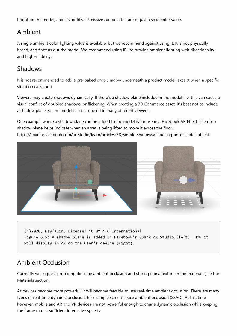
bright on the model, and it’s additive. Emissive can be a texture or just a solid color value.
AmbientA single ambient color lighting value is available, but we recommend against using it. It is not physicallybased, and flattens out the model. We recommend using IBL to provide ambient lighting with directionalityand higher fidelity.
ShadowsIt is not recommended to add a pre-baked drop shadow underneath a product model, except when a specificsituation calls for it.
Viewers may create shadows dynamically. If there’s a shadow plane included in the model file, this can cause avisual conflict of doubled shadows, or flickering. When creating a 3D Commerce asset, it’s best not to includea shadow plane, so the model can be re-used in many different viewers.
One example where a shadow plane can be added to the model is for use in a Facebook AR Effect. The dropshadow plane helps indicate when an asset is being lifted to move it across the floor.https://sparkar.facebook.com/ar-studio/learn/articles/3D/simple-shadows#choosing-an-occluder-object
(C)2020, Wayfauir. License: CC BY 4.0 International Figure 6.5: A shadow plane is added in Facebook’s Spark AR Studio (left). How it will display in AR on the user’s device (right).
Ambient OcclusionCurrently we suggest pre-computing the ambient occlusion and storing it in a texture in the material. (see theMaterials section)
As devices become more powerful, it will become feasible to use real-time ambient occlusion. There are manytypes of real-time dynamic occlusion, for example screen-space ambient occlusion (SSAO). At this timehowever, mobile and AR and VR devices are not powerful enough to create dynamic occlusion while keepingthe frame rate at sufficient interactive speeds.

DrawcallsGenerally, the less separate parts on a model, the faster it will render. Optimizing the number of materials isan important task for content creators. See the section on Publishing Targets for drawcall limits.
A “drawcall” is how the graphics processing unit (GPU) renders 3D models. Batches of vertices that share thesame material are loaded and rendered together. If there are too many drawcalls, the rendering API cannotre-use the same model state between drawcalls, and the frame rate slows down.
Note however the overhead of each drawcall varies from API to API (eg OpenGL vs Vulkan). To evaluate theallowable limits for your application, you will need to assess performance on a case-by-case basis.
(C)2020, Wayfair. License: CC BY 4.0 International Figure 6.1: A chair using four materials
In the chair example above, four materials are being used. This works fine on most real-time devices. If youneed to render the model on a slow device with limited memory or a slow GPU, then a single material for thewhole model may be required.
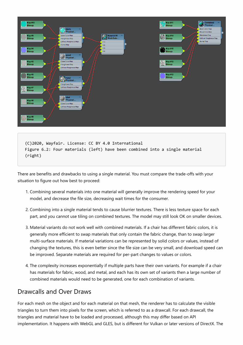
(C)2020, Wayfair. License: CC BY 4.0 International Figure 6.2: Four materials (left) have been combined into a single material (right)
There are benefits and drawbacks to using a single material. You must compare the trade-offs with yoursituation to figure out how best to proceed:
1. Combining several materials into one material will generally improve the rendering speed for yourmodel, and decrease the file size, decreasing wait times for the consumer.
2. Combining into a single material tends to cause blurrier textures. There is less texture space for eachpart, and you cannot use tiling on combined textures. The model may still look OK on smaller devices.
3. Material variants do not work well with combined materials. If a chair has different fabric colors, it isgenerally more efficient to swap materials that only contain the fabric change, than to swap largermulti-surface materials. If material variations can be represented by solid colors or values, instead ofchanging the textures, this is even better since the file size can be very small, and download speed canbe improved. Separate materials are required for per-part changes to values or colors.
4. The complexity increases exponentially if multiple parts have their own variants. For example if a chairhas materials for fabric, wood, and metal, and each has its own set of variants then a large number ofcombined materials would need to be generated, one for each combination of variants.
Drawcalls and Over DrawsFor each mesh on the object and for each material on that mesh, the renderer has to calculate the visibletriangles to turn them into pixels for the screen, which is referred to as a drawcall. For each drawcall, thetriangles and material have to be loaded and processed, although this may differ based on APIimplementation. It happens with WebGL and GLES, but is different for Vulkan or later versions of DirectX. The

cost of overhead is greatly reduced by a command structure and removal of check in drivers for these newerAPI implementations. However, there is always some overhead in the loading process, which makes joiningmore meshes into a single object more efficient.
The exception where there should be multiple meshes is for transparent components. You can think of eachdrawcall like a layer in Photoshop. If a single mesh has some transparency, a single drawcall will not showanything behind the transparent areas. If that transparent part is a separate mesh, the renderer will draw oneon top of the other and the transparent part will layer over the solid mesh, allowing it to be seen through thematerial.
Mesh Count and PerformanceOur recommendation for static assets is to separate all solid meshes from all transparent meshes whenpossible to simplify your model and reduce the amount of artifacting that may be seen in the viewer. You mayjoin all solid meshes into a single object if there is a need to simplify your overall model. All transparentmeshes can be separated into one or more separate objects as need be.
(C)2020, Khronos. License: CC BY 4.0 International Figure 6.3: 149 drawcalls for the Buggy sample model, in the BabylonJS sandbox
The picture above shows the Buggy glTF file, rendered inside the Babylon.js Sandbox web application. Asshown in the panel on the right, within this rendering engine this asset results in 149 drawcalls.
The amount of draws can be significantly reduced during asset creation by batching several parts together,especially if the run-time application does not need to have them separated (for example, to allow hiding /showing parts individually)

Color SpaceThe sRGB color space is commonly used to store and display color images, such as Base Color and Emissivetextures which are often derived from photographs. Colors are stored using a non-linear value curve, similarto the 2.2 gamma response curve of a computer display, and similar to the way the human visual systemresponds to color values. Values are biased using a curve to better store and display human-discernable lightlevels.
All the other textures should be saved using linear values. To save in sRGB linear use a gamma value of 1.0.This stores the values in a purely linear progression of values, with no curve involved, which helps preserve theoriginal mathematical progression of the source content. sRGB linear should be used to store textures thatcontrol purely mathematical features, such as Alpha Coverage, Metalness, Roughness, Normal, and Occlusion.
Base Color and Emissive textures should always be saved in sRGB color space. All other textures should besaved in sRGB linear. Linear textures should always be created, edited, and used in sRGB linear, or else imageand rendering errors will occur.
Most real-time shaders, materials, and viewers will take care of this for you. However, many of the contentcreation software tools do not handle color spaces correctly.
Levels of DetailVersion 1.0.0Last Updated: October 20, 2020
In computer graphics, accounting for Level of detail (LOD) involves decreasing the complexity of a 3D modelrepresentation as it moves away from the viewer or according to other metrics such as object importance,viewpoint-relative speed or position. Level of detail techniques increase the efficiency of rendering bydecreasing the workload on graphics pipeline stages, usually vertex transformations. The reduced visualquality of the model is often unnoticed because of the small effect on object appearance when distant ormoving fast.^1
It should be mentioned that LODs differ from assets authored for specific publication targets. A single assetcreated for desktop web viewing may actually include several LODs designed to be swapped out based onlogic embedded in the viewer. The number of LODs required and the reduction of complexity associated witheach LOD must consider the switching logic of the viewer, and these guidelines make no strictrecommendations regarding LOD configuration at this time. This is a discussion that should be had with thedownstream consumer of the 3D content. By default, the most detailed version of a specific asset for apublishing target shall be considered LOD0, and decreasing levels of complexity shall be referred to as LOD1,LOD2, etc.

Publishing TargetsVersion 1.0.0Last Updated: October 20, 2020
PBR Base AssetThe basis for all asset variants used for publishing is a high-resolution real-time 3D “Base Asset” (sometimesalso referred to as “Source Asset”) that typically has a long lifetime and provides the high-quality, “groundtruth” version for all published variants. This asset should be stored in an uncompressed (loss-free) way, and inhigh resolution. For the materials to be ready for real-time rendering applications, they should already be in amatching format, concretely speaking in a PBR format (recommended: metalness/roughness).
(C)2020, DGG. License: CC BY 4.0 International Figure 99.1: published variants
Understanding where the 3D assets are goingIn order to best make certain decisions when authoring 3D Models, one must have an idea about theintended hardware and software where assets will ultimately be rendered for consumer visualization. Visualfidelity must be balanced with streaming requirements and real-time rendering performance, and often thesame asset should not be used for offline frame rendering as well as augmented reality on a mobile device,for example. The specifics of each software-hardware combination where assets will be rendered areconstantly evolving and may vary, therefore it is recommended to discuss and even test 3D Assets with thedesired rendering platform. Nevertheless, a publishing target should be considered during asset creation and
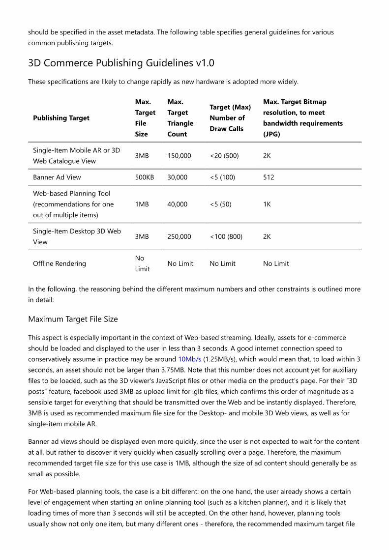
should be specified in the asset metadata. The following table specifies general guidelines for variouscommon publishing targets.
3D Commerce Publishing Guidelines v1.0These specifications are likely to change rapidly as new hardware is adopted more widely.
Publishing Target
Max.TargetFileSize
Max.TargetTriangleCount
Target (Max)Number ofDraw Calls
Max. Target Bitmapresolution, to meetbandwidth requirements(JPG)
Single-Item Mobile AR or 3DWeb Catalogue View
3MB 150,000 <20 (500) 2K
Banner Ad View 500KB 30,000 <5 (100) 512
Web-based Planning Tool(recommendations for oneout of multiple items)
1MB 40,000 <5 (50) 1K
Single-Item Desktop 3D WebView
3MB 250,000 <100 (800) 2K
Offline RenderingNoLimit
No Limit No Limit No Limit
In the following, the reasoning behind the different maximum numbers and other constraints is outlined morein detail:
Maximum Target File Size
This aspect is especially important in the context of Web-based streaming. Ideally, assets for e-commerceshould be loaded and displayed to the user in less than 3 seconds. A good internet connection speed toconservatively assume in practice may be around 10Mb/s (1.25MB/s), which would mean that, to load within 3seconds, an asset should not be larger than 3.75MB. Note that this number does not account yet for auxiliaryfiles to be loaded, such as the 3D viewer's JavaScript files or other media on the product’s page. For their “3Dposts” feature, facebook used 3MB as upload limit for .glb files, which confirms this order of magnitude as asensible target for everything that should be transmitted over the Web and be instantly displayed. Therefore,3MB is used as recommended maximum file size for the Desktop- and mobile 3D Web views, as well as forsingle-item mobile AR.
Banner ad views should be displayed even more quickly, since the user is not expected to wait for the contentat all, but rather to discover it very quickly when casually scrolling over a page. Therefore, the maximumrecommended target file size for this use case is 1MB, although the size of ad content should generally be assmall as possible.
For Web-based planning tools, the case is a bit different: on the one hand, the user already shows a certainlevel of engagement when starting an online planning tool (such as a kitchen planner), and it is likely thatloading times of more than 3 seconds will still be accepted. On the other hand, however, planning toolsusually show not only one item, but many different ones - therefore, the recommended maximum target file

size for this setting is 1MB per item (and even lower values can make sense, depending on the concrete tooland scenario).
Maximum Number of Draw Calls and Triangles
Although real-time engines are able to perform several operations at loading time in order to reduce thenumber of draws used to render an asset, it is recommended to perform a batching of draw calls during assetcreation wherever possible. Usually, different draws correspond to separated logical parts of a 3D model. Eachmodel part typically causes a new draw call. Parts are treated separately during rendering to allow for dynamicdisplay or hiding of individual components, or to allow back-to-front sorting for transparent objects.A proper setup of materials can help to significantly reduce the number of draw calls - see the materialsection for further details.
Similarly, the number of polygons needs to be kept at a moderate level.
For both of these numbers - number of draw calls, and number of polygons - it is important to consider thewhole application, instead of just looking at a single asset. For example, an isolated 3D catalogue view forsingle items may use the full budget for draws and polygons, while the same item should be much moreoptimized when being displayed along with many other ones within a VR scene or within a Web-based floorplanning tool.
For 3D Web and AR renderers, we assume a conservative amount of 500 draw calls and 150K triangles atmaximum, above which we expect the frame rate of real-time rendering engines to likely decrease, for mostclient devices. For Desktop-based renderers, a slightly higher number of 800 draws and 250K triangles is therecommended maximum. For other cases where an item is usually displayed along with other page content,such as banner ad views or Web-based planning tools, smaller maximum numbers of 100 draws and 60Ktriangles (banner ad) and 50 draws and 40K triangles (Web-based planner) draws are recommended. This is toaccount for the fact that multiple assets will be displayed, sharing the same overall budget for draw calls.
Reducing Material Complexity for Previews and Low-End Devices
A typical compact asset for publication will contain the following texture maps:
Base ColorORM (Occlusion / Roughness / Metallic))NormalsEmissive
With standard material models evolving further, additional maps may be used as well. For low-end devicesand preview versions, however, it may be necessary to reduce the amount of texture maps when simplifyingthe asset. For example, a 100KB preview version of a typical 3D commerce asset will not usually not contain anormal map, but instead use the existing file size budget rather for a low-resolution base color texture and asimplified mesh.
The glTF 2.0 specification provides hints about the priorities (descending from top to bottom) of the normalmap, occlusion map and emissive map, as well as a description of the impact of dropping a specific map:

Map Rendering impact when map is not supported
Normal Geometry will appear less detailed than authored.
Occlusion Model will appear brighter in areas that should be darker.
EmissiveModel with lights will not be lit. For example, the headlights of a car model will be off insteadof on.
Following these hints, we suggest the following priorities (descending) of the different maps for 3D commerceassets:
1. Base Color2. ORM3. Normals4. Emissive
To create fast-loading, ultra-compact assets, optimization pipelines can therefore drop the maps in reverseorder of their priorities, to satisfy a requirement for a desired maximum target file size.
Creating Target Specific AssetsWhile there are various techniques available to create optimized 3D models for certain targets, a commonapproach is to author assets in a derivative approach based on a high density, high quality base model - the3D Base Asset.Automated workflows can then be used to produce optimized, low-poly variants for different publishingtargets.In contrast to the 3D base asset, which is usually supposed to be authored by human 3D artists, the optimizedvariants for publishing typically don’t need to be editable and can therefore contain highly adaptive, irregulartriangle meshes (instead of quad meshes) to exploit the GPU’s polygon budget as efficiently as possible, forexample.Furthermore, optimized assets may rely on texture atlases (especially for non-tiled texture content), in order toreduce the amount of textures to be transmitted and rendered to a necessary minimum.This entire process can be performed by automated tools, such as DGG RapidCompact or MicrosoftSimplygon.For further details on the different aspects of optimization, see the sections on mesh optimization andcreation of normal maps, for example, as well as the section on LOD )creation.

glTF & USDZVersion 1.0.0Last Updated: October 20, 2020
glTF 2.0 Features / Extensions & USDZ Comparison
Official Extensions
Link to details on glTF extension
Description Official Extensions USDZ
Draco compression KHR_draco_mesh_compression No
Punctual Light support KHR_lights_punctual No
PBR specular glossiness KHR_materials_pbrSpecularGlossiness No
Unlit material KHR_materials_unlit No
Repeatable, scalable UV KHR_texture_transform No
Clearcoat KHR_materials_clearcoat Yes (equivalent)
glTF 2.0 Features and USDZ Parity
Link to details on glTF specification
Description Features USDZ
At least 2+ UV Sets TEXCOORD_0, TEXCOORD_1 Yes
Vertex Color COLOR_0 No
Alpha Coverage Alpha Coverage: OPAQUE Yes
Alpha Coverage Alpha Coverage: MASK, alphaCutoff No
Alpha Coverage Alpha Coverage: BLEND Yes
Double-sidedness doubleSided Yes
Animation interpolation linear, step, cubic spline Yes
Morph targets Morph target No
Rotation animations rotation Yes
Translation animation translation Yes
Scale animation scale Yes
Joint and skin Animated joints and skins Yes

Related Documents


