Real Life Application of Disaster Recovery Faisal Choudry EMC Proven Professional Knowledge Sharing 2009 Faisal Choudry Magirus, UK [email protected]

Welcome message from author
This document is posted to help you gain knowledge. Please leave a comment to let me know what you think about it! Share it to your friends and learn new things together.
Transcript

Real Life Application of Disaster Recovery
Faisal Choudry
EMC Proven Professional Knowledge Sharing 2009
Faisal ChoudryMagirus, [email protected]

2009 EMC Proven Professional Knowledge Sharing 2
Contents INTRODUCTION 3
THE CHALLENGE 4
Should we bother with expensive DR? ..................................................................................................4 How Much Time? ...................................................................................................................................5 Regulation ...............................................................................................................................................6 What else is driving the need for High Availability?.............................................................................8
THE RIGHT SOLUTION 10
Recovery Point Objectives and Recovery Time Objectives ................................................................11 Consistency ...........................................................................................................................................13 Crash Consistency.................................................................................................................................13 Application Consistency .......................................................................................................................13 Categorise the Data ...............................................................................................................................14
THE DR REALITY 16
Project Objectives .................................................................................................................................16 Case Study Product Solution Set ..........................................................................................................17 Delivering an SRM Configuration .......................................................................................................20 The Hardware Configuration................................................................................................................22 SRM Architecture .................................................................................................................................23 Protected Site ........................................................................................................................................23 Recovery Site ........................................................................................................................................23 Protection Groups .................................................................................................................................24 Recovery Plan .......................................................................................................................................25 Testing DR with SRM ..........................................................................................................................26 In Case of Disaster…............................................................................................................................27
SRM ISSUES AND HOW THEY WERE ADDRESSED 28
EMC Solutions Enabler ........................................................................................................................28 SRM Storage Prerequisites ...................................................................................................................29 MirrorView Consistency Groups..........................................................................................................29 SnapView Snapshots.............................................................................................................................32 LUN Masking and SRM.......................................................................................................................33
IF TESTING JUST ISN’T ENOUGH 34
Contingency ..........................................................................................................................................36 No Auto Failback..................................................................................................................................37 Resynchronisation.................................................................................................................................39 Suggested Architecture .........................................................................................................................39 What shall we use for Recovery and when? ........................................................................................40 Categories types of Failures..................................................................................................................40
CONCLUSION 43 REFERENCES 44 BIOGRAPHY 45 Disclaimer: The views, processes, or methodologies published in this compilation are those of the authors. They do not necessarily reflect EMC Corporation’s views, processes, or methodologies.

2009 EMC Proven Professional Knowledge Sharing 3
Introduction Data Recovery is useless without access to the applications that created the data in
the first place. So it doesn’t matter how “state of the art” customers’ Business
Continuity (BC) and Disaster Recovery (DR) solutions are. If the organization
purchasing the solution has no clear understanding or procedure to invoke a BC plan
or DR process when a situation occurs, and cannot tie the data and applications back
together again, they are not going to be able to recover from any level of disaster
within an acceptable period of time, if at all.
This article highlights the key issues faced by customers and technicians during
projects involving the design and implementation of DR solutions, particularly within
the Small to Medium size Enterprise (SMEs). Business Continuity includes failing
over all functions of a business not just the IT systems, so encompasses employee,
building power, and alternate facilities logistics. A subset of BC would be DR
planning for the IT systems. This paper focuses solely on recovery of the IT
systems.
The article is in a case study format to support the issues presented as well as to
highlight the problems encountered. The setting is a large Housing Association
within the UK and involved setting up a BC plan, which included solutions for High
Availability (HA), and DR of IT systems to an alternate site. Technologies from both
VMware and EMC were used as part of the solution including VMware’s vCenter Site
Recovery Manager (SRM) which was added to the solution in order to facilitate
failover of the servers and applications to an alternate site.
Audience The intended audiences for this paper are customers, managers, IT managers,
storage architects, engineers, DR teams, EMC technical staff and partners. The
reader should have a basic understanding of VMware, EMC CLARiiONs, and
vCenter Site Recovery Manager for the technical sections later on.

2009 EMC Proven Professional Knowledge Sharing 4
The Challenge Should we bother with expensive DR? Today’s companies are more aware of terms such as Disaster Recovery, Disaster
Planning and High Availability. One reason is the immediate global media coverage
we have today. People are aware of a natural disaster or terrorist attack anywhere in
the world within minutes. Aside from the appalling loss of life during events such as
the attacks on September 11th, or when New Orleans was devastated by hurricane
Katrina, people were very conscious of damage to businesses. Hurricane Katrina
resulted in excess of $200 Billion in losses due to destroyed businesses. These
events, rare as they are, have certainly made companies more aware of their
vulnerabilities and the importance of being able to protect and recover their most
valuable asset, their data.
“While Hurricane Katrina battered the Louisiana headquarters of SCP Pool Corp.,
just north of New Orleans, the company's disaster recovery and relocation plan kept
its business and data safe. Some 500 miles away, the $1.4 billion distributor of
swimming pool supplies was operating from a VeriCenter Inc. centre in Dallas.1”
But events such as the ones above are extremely rare. A Gartner study estimates
that nearly 80% of downtime is actually planned. That means that the type of events
that will cause organisations applications to be inaccessible will be events such as
system upgrades taking place across IT systems and engineer errors.
Thousands of other types of events can disrupt a business. They include unhappy
employees who may sabotage systems or delete/steal critical data. Brown outs and
frequent power cuts can occur during the summer when demand for power is
extremely high.
In South Africa, companies have been hit with a wave of frequent power cuts, as the
power companies there have not had the capacity to supply the huge growth in
demand. The national supplier of power in South Africa (Eskom) issued an alert
during 2007 and warned customers to expect 2 to 3 hours a day of power cuts.
During a visit to Johannesburg, we experienced power cuts every afternoon.
1 Katrina, IT lessons in Disaster Recovery.

2009 EMC Proven Professional Knowledge Sharing 5
Glitches are another cause for loss of business; database glitches or complete
system crashes. On September 8th 2008, the London Stock Exchange (LSE) was
unable to trade due to what they called a “computer glitch”. On that particular day,
the U.S banks Freddy Mack and Fannie Mae were nationalized by the U.S
government. The market rose 4% from the news, in fact the Dow Jones had its
largest increase for months and the LSE were unable to trade till 16:30 GMT
because their systems were down till then. That’s half an hour’s trading before the
closing bell.
How Much Time? So just how long can you be out of business before you are out of business? Why
make that huge investment if you’re not going to see immediate returns? For some
organizations, it’s no longer a choice; governments have stepped in and made it
mandatory for certain types of companies to have a disaster recovery plan, due to
the sector the company is involved in, for example banking. For companies that do
have a choice and are not forced by legislation to implement a DR solution, should
they invest in expensive HA solutions and DR plans?
Some businesses would be less or more affected by IT systems not being
accessible. The effect depends on the nature of the business and how dependent
the company is on their IT systems. Some could function quite capably without them
for a period; others would be paralysed. 25 years ago companies may have been
able to move to an alternate site and run procedures manually while systems
remained inaccessible, today this is less feasible with the automation of the majority
of a company’s processes.

2009 EMC Proven Professional Knowledge Sharing 6
What would be the financial implications from a disaster which renders systems
inaccessible and therefore halts the business from operating? Two types of costs
should be considered: tangible and intangible costs. The tangible costs are the
obvious financial costs because the business is no longer functioning. The
employees are a cost to the company, if they can’t actually work the company is
losing money. An estimate of the impact can be calculated using the average wage
per hour of an employee and multiplying this by the number of employees within the
site affected.
The costs that are not so obvious include the loss of business over a longer period of
time. Gartner estimates that two out of five enterprises that experience a disaster go
out of business within five years. The problem with downtime is that customers will
find an alternative and go elsewhere to do business. In the world of online
businesses, 24/7 access and shopping, if a customer experiences a delay of 10
seconds or more while accessing a web site, they will simply search for another site
and take their business elsewhere. That’s due to a simple delay. One can only
imagine the number of customers a business stands to lose when it is actually out of
action. Disaster planning expert Fenton2 gives an example of part of a store’s
disaster recovery plan, which was to provide transport to customers to an alternate
store. They’d rather spend the extra money on providing the additional transport
than risk losing customers to a competitor across the street.
Regulation A number of regulations, such as Sarbanes-Oxley, HIPAA, Gramm-Leach Bliley, and
other laws demand that organizations protect the availability of data, making HA and
disaster recovery capabilities not just “nice to haves,” but also legal requirements for
many companies. Furthermore, within certain industry segments, financial auditors
have included HA in their checklists3.
An illustration follows on the next page.
2 Disaster Recovery and Contingency Planning in Extreme Times – George Fenton. 3 Ensuring System Accessibility with High Availability Technology Written by HENRY MARTINEZ

2009 EMC Proven Professional Knowledge Sharing 7
Figure 1: U.S and UK Legislation - Source: Commvault - http://www.commvault.com/
HIPPA
SEC17a-4
21 CFRPart 11
SOX
Reasons to Keep Information (US)
Today Today 6 6 MthsMths6 6 MthsMths 1 Yr1 Yr1 Yr1 Yr 2 Yrs2 Yrs2 Yrs2 Yrs
SarbanesSarbanes--Oxley (Public Companies)Oxley (Public Companies)
3 Yrs3 Yrs3 Yrs3 Yrs 5 Yrs5 Yrs5 Yrs5 Yrs 7 Yrs7 Yrs7 Yrs7 Yrs 10+ Yrs10+ Yrs10+ Yrs10+ Yrs
7 years in relation to audit/review7 years in relation to audit/review
Pediatric medical records
Adult medical records
security rule implementation documents
21 years21 years
6 years from the date of creation6 years from the date of creation
after patient's deathafter patient's deathUp to 2 yearsUp to 2 years after patient's deathafter patient's deathUp to 2 yearsUp to 2 years
All account records
statements, transaction records,and associated communications
member registration /corporate documentation
3 years3 years
Life of the businessLife of the business
6 years after account closed6 years after account closed
Clinical trials and approvals
Food
Drugs
Manufacturing of biological products
Min 2 yearsMin 2 years
Min 3 yearsMin 3 years
5 years after manufacturing5 years after manufacturing
Up to 35 yearsUp to 35 years
Companies Act1985
FinancialServices
Health&Safety
DPA Act
Legal
Reasons to Keep Information (UK)
Today Today 6 6 MthsMths6 6 MthsMths 1 Yr1 Yr1 Yr1 Yr 2 Yrs2 Yrs2 Yrs2 Yrs
Limitations Act 1980Limitations Act 1980
3 Yrs3 Yrs3 Yrs3 Yrs 5 Yrs5 Yrs5 Yrs5 Yrs 7 Yrs7 Yrs7 Yrs7 Yrs 10+ Yrs10+ Yrs10+ Yrs10+ Yrs
Records relation to children until they are 21Records relation to children until they are 21
Income Tax Regulations 1993
Accounting Records
Taxes Management Act 1970
Tax, NI Returns, Pay Records Tax, NI Returns, Pay Records -- min 6 yearsmin 6 years
Wage/salary records Wage/salary records –– 6 years6 years
COSHH Regulations 1999
Ionizing Radiations Regulations 1999
40 years from the date of the last entry40 years from the date of the last entry
Until a person reaches 75 or at least 50 yearsUntil a person reaches 75 or at least 50 years
HR Records
Personal Information As long as is necessaryAs long as is necessary
companiescompanies3 years for private, 6 years for public3 years for private, 6 years for public companiescompanies3 years for private, 6 years for public3 years for private, 6 years for public
FSA Regulatory Records Keeping Destroy after 7 yearsDestroy after 7 years
Corporate Records All records permanentlyAll records permanently
Contracts / AgreementsContracts / Agreements 6 years, Under seal 6 years, Under seal -- 12 years after conclusion of contract12 years after conclusion of contract
Personnel Records Personnel Records -- Destroy after 6 yearsDestroy after 6 years
destroy after 5 yearsdestroy after 5 yearsAppraisal RecordsAppraisal Records destroy after 5 yearsdestroy after 5 yearsAppraisal RecordsAppraisal Records
destroy after 3 yearsdestroy after 3 yearsSickness / Leave RecordsSickness / Leave Records destroy after 3 yearsdestroy after 3 yearsSickness / Leave RecordsSickness / Leave Records
Health & Safety at Work Act 1974 Accident Records Accident Records –– 3 years3 years
Substance Exposure Substance Exposure –– general 5 years, personal 40 years (health surveillance)general 5 years, personal 40 years (health surveillance)

2009 EMC Proven Professional Knowledge Sharing 8
Not only do organisations need to protect their information and ensure it is
recoverable in the event of a disaster, they have a duty to ensure their data is stored
for durations specified by legislation, and that it is accessible when asked to produce
it. Companies already struggle with the amounts of data they have to store, and with
the rate at which data is growing, and with the regulatory requirements also
increasing, it is not getting any easier. A number of high profile cases involving
massive fraud and company collapse during the last few years (WorldCom, Enron
and Tyco) have helped to increase the amount of legislation, above all Sarbanes-
Oxley Act or SOX which the US Senate and House of Representatives passed on
30th July 2002. The act affects not only U.S. companies, but many companies here
in the UK, including small businesses. The Legislation within Europe is also nearing
compliance with SOX.
What else is driving the need for High Availability? The internet is a big factor, with online banking and stores and the ability to shop
from anywhere in the world, from your desk, 24/7 access is a necessity in today’s
world. This factor alone has driven down recovery times or Recovery Time
Objectives (RTO). Where in the past a day of down time may have been acceptable,
in today’s global village, a few hours of downtime could result in huge financial
losses.
This reduction in recovery times, alongside vast increases in the amount of data to
store and protect, means that many of the companies that still use traditional
methods to create copies of their data and store them off-site are faced with an up hill
struggle. Data will continue to grow, and recovery times will continue to decrease.
The traditional forms of protection like backups have not kept pace with the growth of
electronic data. Using only backups as the primary line of defense against disaster
has distinct disadvantages. Backups are generally slow and due to the amounts of
data and the rate of growth of data, are taking longer to complete. To recover from
an all out disaster using only backups would involve an absolute gigantean effort for
most IT support teams. Getting tapes off site as part of a DR process is also a risk;
an astounding number of organisations lose tapes during transit. Banks and
Governments have been known to lose their tapes containing confidential customer
data. In November 2008, Harvard Law School lost some unencrypted tapes
containing personal data on some 21,000 clients of its legal clinic. According to the
press, the tapes were lost by a technician who was transporting them on the subway.

2009 EMC Proven Professional Knowledge Sharing 9
Data growth is forecast to continue at unprecedented levels; the traditional methods
of protecting data may have worked well in the days of single servers using small
amounts of storage but today’s world is very different. Backups do serve their
purpose, and as one part of an overall solution, work well.
Henry Martinez of Vision Solutions identifies a number of other factors driving the
move to HA solutions. Companies want to reduce costs, reduce power consumption,
and decrease hardware, as well as the amount of physical space used. They also
want to lower the amount of administration, “manage more with less”, and want a
better return on their investment, therefore improving utilization of their server’s
hardware. Server Virtualisation is one of the biggest growth areas within the IT
sector. However, adding numerous virtual servers into one physical box means an
enormous increase in the amount of storage required by a single physical server.
This is one of the factors driving the growth in storage. The ease with which a team
is able to deploy new servers using virtualization is astounding. No need for
purchase orders, or even new hardware, a new virtual server can be created with the
click of a mouse making use of available capacity and deployed within minutes to any
part of the business. According to VMware EMEA, only 10 percent of physical
servers within the EMEA region have been virtualized to date.
Due to increases in the amount of data, maintaining separate islands of storage is
not practical, so purchasing a Storage Area Network (SAN) has been the next logical
step after virtualisation. Centralizing storage eases administration and makes data
growth much easier to manage and keep up with. However companies certainly feel
more vulnerable “storing all their eggs in one basket.” A single physical server now
contains many virtual servers running multiple critical applications and databases,
alongside a single storage array containing all data, naturally creates concern, as a
single failure would be disastrous.

2009 EMC Proven Professional Knowledge Sharing 10
The Right Solution There are so many different ways to protect data, where do you start? Vendors have
many different solutions for protection, whether using traditional backups or some
form of replication: host, storage or appliance based. For example, EMC has a
number of replication products in the market, and a number of these additionally bolt
together to produce further enhanced protection and recovery mechanisms.
Examples of some of these products are RepliStor®, San Copy™, MirrorView™,
Recoverpoint, and Replication Manager to name a few.
Picking the right method of protection and piecing the correct solution together is
confusing; start by asking questions regarding the business: What is the nature of
the business? What type of protection or availability does the company require, and
why? Break the requirements down by data and application types. Differentiate
component parts of the business as well as their importance, as certain applications
or functions within the company will be critical, but not all.
Budget will always be a limiting factor when shopping for a solution; disaster recovery
tools don’t come cheap. Network computing magazine ran a survey in 2007 and
found that the budget was the number one pain point for planners seeking to
develop a DR strategy. Other obstacles included vendors’ claims that were
confusing, and the sheer number of solutions in the market which again created
confusion and proved daunting for customers. But these technologies should not be
seen as unnecessary expenses. Provided the acquisition of the equipment is
supported by a solid business case, and was purchased based on the business
requirements, they reduce the high risks and the extortionately high one time cost
associated with downtime, possibly saving the business from closure.

2009 EMC Proven Professional Knowledge Sharing 11
Recovery Point Objectives and Recovery Time Objectives How long should it take to run through the disaster recovery procedure and recover
data, how much data can a company afford to lose, what is acceptable to the
business?
From a financial perspective, once disaster strikes a company, income stops but
expenses continue. What financial impact is the absolute limit for the company in
question? At which point would the company be unable to sustain the impact from a
given disaster? Once you have an idea of this cost, you have the Recovery Time
Objective. The fact is the longer a company is offline due to disaster, the greater the
expense, however the faster the recovery process, the more expensive the solution
tends to be.
Recovery Point Objectives (RPO) defines the maximum amount of data the company
or department can afford to lose during an event.
Recovery Time Objectives (RTO) defines the maximum amount of time allowed for
recovery procedures to complete. The RTO is a marker; recovery needs to have
happened within a certain time frame. The RPO is helpful in selecting the best
products for the job, for example whether to use a synchronous replication product or
an asynchronous one, or whether to automate the recovery solution in order to speed
the process.

2009 EMC Proven Professional Knowledge Sharing 12
RPOs and RTOs should be driven by the business, and not just the IT departments.
Different parts of the business may have different RPOs and RTOs. Some parts may
not need a form of replication; they may be able to afford longer periods of downtime,
but for parts of the business, down time could amount to huge losses. Basing the
recovery strategy purely from an IT centric view may lead to a larger than necessary
investment that may not protect all the important areas of the business.
The applications need to be listed in order of importance, and categorized
accordingly, without the application; the data is not much use. The Disaster
Recovery journal lists Exchange recovery as the number one pain point in 2007 and
2008. “It’s on the top of every SMB and SME’s to do list, and every IT managers”.
Additionally applications tend to have their own “Best Practice” documents written by
their vendors on how to protect and recover them. So for example, methods for
protecting Exchange servers or SQL servers can be quite different.

2009 EMC Proven Professional Knowledge Sharing 13
Consistency Which type of consistency will be required for the applications that you’re going to
protect? Operating systems and applications all react differently to system crashes
and recovery. Databases are based on the integrity of the multitude of transactions
taking place in the background. Different recovery solutions will give better or worse
recoverability. The integrity of the data is dependent on the write process used to
create that primary copy of data, and that depends on the application, so again
looking at each application and forming a recovery solution specific to it’s
requirements is key. There are different types of data consistency, and different
recovery solutions will achieve different types of consistency.
Crash Consistency This is the equivalent of pulling the power from a server while the applications are
running, and then powering up the server again. Replication solutions that have
limited knowledge of the applications are easier to put together. During recovery you
are reliant on the application’s capability to start up on its own merits, or possibly with
some intervention. Following a fail-over, the data will not have transactional
consistence, if transactions were in-flight at the time of the failure. In most cases
what occurs is that once the application or database is restarted, the incomplete
transactions are identified and the updates relating to these transactions are
“backed-out” or some extra procedures or tools may be required.
Application Consistency There are ways of ensuring that if a copy is taken, or if a system is shut down, all
necessary transactions within a database are complete and caches are flushed in
order to maintain consistency. Scripts can be written, following best practice for each
application to ensure processes take place in a certain order, or there are
applications which can automate these procedures for each application. Some
technologies use agents which are application specific. The choice is again down to
importance of data, RPOs, RTO’s and the available budgets within the organisation.

2009 EMC Proven Professional Knowledge Sharing 14
Categorise the Data Choosing the technologies to protect the data from a business perspective rather
than an IT centric perspective means more suitable matches of HA technologies to
the tier of data being protected. The value of the data should be the driver for
choosing the appropriate technology.
Figure 2: Tiers of Data.
RECOVERY TIERSnapshots, Replication, SRM, Geo Clusters• Improves recovery time and recovery points• Reduces impact of backup on production data
1RECOVERY TIERSnapshots, Replication, SRM, Geo Clusters• Improves recovery time and recovery points• Reduces impact of backup on production data
1
Backup copies, disk-to-disk, disk-to-disk-to tape• Less data to backup and recover• Reduced number and use of tapes
PROTECTION TIER2 Backup copies, disk-to-disk, disk-to-disk-to tape• Less data to backup and recover• Reduced number and use of tapes
PROTECTION TIER2
ARCHIVE TIERActive archive and migration, offsite tape vault• Reduces size of data to store and backup• Ensures persistent copy and retention of data
3 ARCHIVE TIERActive archive and migration, offsite tape vault• Reduces size of data to store and backup• Ensures persistent copy and retention of data
3
Speed of Recovery • Improved recovery time and increased recovery points
Len
gth
of
Data
Rete
nti
on
•R
ete
nti
on
po
lici
es
dete
rmin
ed
by d
ata
cla
ss
Speed of Recovery • Improved recovery time and increased recovery points
Len
gth
of
Data
Rete
nti
on
•R
ete
nti
on
po
lici
es
dete
rmin
ed
by d
ata
cla
ss
Source: Veeam - http:// www.veeam.com
Tiering data or categorizing it, rather than putting it all into a single pigeon hole,
requires implementing some form of Information Lifecycle Management (ILM).
Traditionally this has been used within mainframe environments (largely driven by the
cost differential between different storage media types), but within the open systems
world is still a growing methodology, and not easily accepted or understood. End
users still seem to throw more and more storage at their data without any thought
about the importance or age or type of data being stored. A simple analogy, I don’t
put all of my food into the same compartment within my refrigerator! ILM is outside of
the scope of this paper but should form part of an organisations’ data recovery
strategy.
SAN hardware, expensive Fibre channel disks and SAN or appliance based
replication technologies will not be appropriate for every piece of data within the
company. So choose accordingly. Something like SRM would be pointless for data
that hasn’t been accessed in months, so archive it.
Illustration follows on next page.

2009 EMC Proven Professional Knowledge Sharing 15
Figure 3: Cost of different types of DR solutions.
Source: Veeam - http:// www.veeam.com

2009 EMC Proven Professional Knowledge Sharing 16
The DR Reality
The inability to use newly purchased “state of the art” technologies to recover from a
disaster is one of the most common reasons that Disaster Recovery plans fail. There
is a lack of ownership from the company involved, and the right people very often are
not educated on the newly installed systems. Organisations perceive that when
disaster strikes, miraculously, everything will work from the press of a button, no
matter how severe the disaster. They have not gone through any form of risk
analysis, or education in relation to the new systems, and certainly haven’t actually
practiced any DR procedures. All too often, when recovery procedures are written,
they gather dust in a drawer and are never updated. So when disaster strikes so
much has changed; the original documents are of no use.
The Housing Association Case Study This case study involves one of the UK's largest and most successful providers of
homes for rent and sale, providing services to tens of thousands of people across
London and the south east. The Group consists of a number of housing
associations, owning and/or managing more than 40,000 homes. They manage loan
facilities of up to £550 million with some of the sector's leading funders. The
Association provides:
• Permanent and Temporary housing, management services,
• Affordable home ownership: in order to help more people get a foot on the
property ladder.
• Key worker housing: places London's essential workers; nurses, police
officers, teachers.
• Supported housing: providing of supported housing for the elderly and for
people with special needs.
Project Objectives The association’s objectives:
• Make the I.T portion of the business more efficient
• Reduce the amount of server and storage administration to reduce TCO
• Reduce the physical number of servers within each building
• Reduce power consumption and hardware costs

2009 EMC Proven Professional Knowledge Sharing 17
• Increase productivity by reducing problems, for example reducing the amount
of server hardware.
• Decrease reliance on tape backups as the primary line of defense in the
event of disaster
• Put BC and DR plans in place
• Test the DR plans regularly, in house
• Comply with regulatory requirements
Case Study Product Solution Set The following sections describe the different products used within the case study.
The products were specifically picked because of their compatibility. These products
form the core of this solution and are paramount to tackling the issues mentioned in
the earlier part of this document. The products are:
• EMC’s CLARiiON
• VMware’s ESX server
• VMware’s Site Recovery Manager (SRM)
EMC CLARiiON The CLARiiON is EMC’s very successful mid-range storage platform. The CLARiiON
was the first Fibre Channel array to be released with ISCSI ports alongside Fibre
Channel ports on the same array, the customer can use either one or both
technologies at the same time.
Two CX3-10 models were purchased for this solution. The CX3-10 is the 3rd
Generation of the CX family, and the 10 is the entry level model. It can span up to 60
drives, Fibre channel or SATA. The Fibre front-end ports support up to 4Gbps and
the ISCSI up to 1Gbps. SnapView and MirrorView enablers were also purchased.
SnapView gives the CLARiiON the ability to take either snapshots (point in time
copies) or to make full clones of a source LUN within the CLARiiON. SnapView also
enhances other functions such as the ability to test and enhance backup strategies
but is beyond the scope of material covered here.
MirrorView Asynchronous (A) is for replication between the two CLARiiONs at either
site. In the event of total site or array loss, one can select the LUNs at the
secondary/DR site and promote them to primary LUNs, and then run all applications
out of the DR site.

2009 EMC Proven Professional Knowledge Sharing 18
SnapView compliments MirrorView as it adds the ability to test replication without
interrupting it, by simply taking either a snapshot or clone of either the Primary or
Secondary LUN involved in replication. For SRM’s “Test” function to work, the
SnapView enabler is a prerequisite. SRM is then able to take Snapshots of the
secondary copies created from the replication process and confirm the content and
integrity of the data held on the mirrored LUNs.
VMware ESX The vast majority of deployed servers run on physical machines, companies are
beginning to understand the huge advantages virtualization can create for them.
ESX enables an organization to virtualise their physical servers, so helping them to
reduce costs associated with running and delivering servers into different parts of
their business. It vastly increases the flexibility one has in managing that
environment, processes such as maintenance can be performed online without
having to disrupt the business. Normally maintenance would mean shutting down
key servers. ESX uses advanced technologies such as High Availability (HA),
VMotion, Distributed Resource Scheduling (DRS), within a cluster configuration to
help provide business continuity.
VMware vCenter Site Recovery Manager (SRM). SRM is still a fairly new product, but is making quite an impact within the virtualisation
and storage space. The product addresses the issues and complexities related to
creating disaster recovery plans, and can automate disaster recovery by failing data,
servers (virtual) and applications over to an alternate site. It is not my intention here
to cover a step by step installation of SRM as there are two very good papers that
already cover this in depth, listed in the glossary:
SRM does make the DR process a much easier and more manageable process for
the customer. It’s not entirely automated, which is not a bad thing. The decision to
launch a DR rests with a human, not a computer, and that decision should be taken
by the appropriate person within a chain of command or governance structure (some
form of DR team), following a specific chain of trigger events. As well as the
capability to automate failover, it also has the ability to test the DR solution, and
automates this process.

2009 EMC Proven Professional Knowledge Sharing 19
SRM’s functions as a Disaster Recovery Solution4. It combines VMware’s ESX
product with a number of storage vendor products. Because ESX has no inbuilt
replication technology it is dependent on the underlying SAN technology to replicate
any production data offsite. SRM uses Site Recovery Adapters (SRA’s) that enable
SRM to interface with that particular vendor’s storage. In this case we combined
SRM with EMC’s CLARiiON CX3 product range, using MirrorView / A. Administration
of SRM is via a Graphical User Interface (GUI) provided by adding a plug-in to the
Virtual Centre Client, so there are no new applications for VMware administrators to
have to learn.
Figure 4: SRM Plug-in.
In the event of disaster, without the applications and servers that created the data,
the LUNs are of little use, so failing over only LUNs to an alternate SAN has limited
benefit. One of the objectives of this project was to reduce the amount of time the
systems would be unavailable in the event of a complete site failure, and have the
capability to recover the failed site at an alternate location within a specified RTO and
RPO. The housing Association were capable of recovery at an alternate site using
tape, but it would probably take a day or two, they had never had to implement or
practice the procedure before, so we did not have a baseline measurement.
SRM automates complex procedures. The customer is able to test their DR
installation with the push of a button. With the click of a single button, the customer
can failover their production data to a recovery site when disaster strikes. SRM
makes shorter RTOs possible. It takes time if the majority of processes are manually
driven. During a real disaster, the simplest procedure can seem very complex
among the panic and chaos. SRM runs the complex recovery plans by performing
the procedures previously set within the application by the IT administrators.
4 SRM can be used to move data and virtual servers permanently, to an alternate site.

2009 EMC Proven Professional Knowledge Sharing 20
Delivering an SRM Configuration Configuring VMware’s SRM requires as much knowledge of the underlying storage
as of ESX. In fact, it helps if one has expert knowledge of the storage technology
being used. In this case the SAN consisted of EMC CLARiiONs, SnapView and
MirrorView /A replication.
At the time of the SRM configuration, the Housing Association already had an
existing SAN with ESX servers and EMC CLARiiONs at either site replicating using
MirrorView/A (an earlier project delivered by us). When we delivered the initial
project to put in VMware and the EMC SAN, SRM had not at that time been released
on the market. Waiting for the release of SRM before delivering any part of the
project was not a realistic option, as the Housing Association had a business
requirement and deadline by when they needed a large portion of their physical
servers virtualised and replicated offsite.
Figure 5: Before Installation of ESX or SAN.
After we implemented the new systems, the data at the two sites was replicated
using MirrorView/A, and tested by creating snapshots of the secondary mirrors
(SnapView). A manual procedure was created so the end user could also
periodically test their replication using VMware, MirrorView and SnapView. However,
all these technologies were very new for the teams within the organization, running a
test manually would not be easy without some form of training and practice. The
project took the Housing Association from an environment where they had a large
number of physical servers (see Figure 5), growing storage, BC and DR that was
2009 EMC Proven Professional Knowledge Sharing 21
based around tape backups, to an environment where they had effectively reduced
the number of physical servers within their data centre, centralized their storage and
reduced their RPO and RTO’s by enhancing their BC and DR options. However, the
question of how they would be able to run a DR process themselves using their new
technologies still remained.
Figure 6: Post ESX and SAN Installation.
A mixture of connectivity options had been used on the CLARiiONs, so the ESX
hosts all connected to the SANs via Fibre channel hbas (Qlogic), the CLARiiONs
connected over the WAN over ISCSI, this connection was used for the array based
replication. Bandwidths, latency had all been previously checked to ensure there
would be adequate bandwidth to replicate the required amount of data and achieve
the requested RPO and RTOs.*
*EMC has a process know as a Solutions Validation (SVC). A number of the more
complex pieces need to go through this, so products such as MirrorView, Replication
Manager would all need supporting SVC paperwork sent to EMC for validation before
implementation. It is carried out by the reseller before implementation and includes
information on any WAN links between sites, bandwidth, and applications. The EMC
SVC team then either accept or decline (as the solution may not work) the solution
based on the information sent to them.

2009 EMC Proven Professional Knowledge Sharing 22
The two SANs at either site had been configured so both arrays would hold a number
of primary LUNs, so local users at each site could access their data locally and not
have to go across any WAN connections. In terms of replication, it meant replication
was set up in both directions. Both of the CLARiiONs were sources and targets.
The Hardware Configuration All the hardware, systems, and software used to implement the solution at the
Housing Association are listed below.
Figure 7: Hardware and Software.
2 at each site
Quantity
Cx3-10 ClariionFLARE 3.26SnapView
MirrorView/A
1 at each site
DELL PowerEdge Servers 2950Running ESX 3.5
4 at each site
Fibre Channel SwitchBrocade DS5000
Network Switches/RoutersCisco
EquipmentHardware
*see VMare’s SRM compatibility matrix for current supported versions, prerequisites and any required patches.
Software VersionsSoftware Title Version
Vmware ESX Server 3.5 update 3
Vmware Site Recovery Manager 1 (will be updating to update 1 during 1st Qu 2009)
EMC Solutions Enabler 6.5.2.0
.NET Framework 2.0
EMC SRA for SRMFor MirrorView/A and /S
Over Fibre or ISCSI1.2.0.4
2.5 update 1Virtual Center Server
SQL Server 2005 Express

2009 EMC Proven Professional Knowledge Sharing 23
SRM Architecture
Figure 8: The SRM Architecture.
Configuring SRM for DR is about creating the DR recovery plans. It involves
selecting the resources you want protected and then selecting where these
resources should fail over to at the alternate site. SRM defines resources by:
Protected Site The production LUNs sit here. So this is the site you are protecting as all the servers
and data which are accessed are based here (the primary copies).
Recovery Site If the production site or data were lost or inaccessible, and not recoverable at the
primary site within a reasonable amount, where would you want to fail over the
resources to? At the Recovery site, this is where the secondary copies of all the
resources would now start up, at a Disaster Recover site, also sometimes called a
“bunker site.”

2009 EMC Proven Professional Knowledge Sharing 24
Figure 9: The Protected and Recovery Sites.
SRM documentation continuously refers to either the protection or recovery site
during its configuration (Figure 9). Make sure you know which site is which. If the
organization’s data is clearly all production (Primary) at site one and site two is only
used for DR purposes, then the configuration is straight forward, the protected and
recovery sites are fixed. However companies can hold production (primary) data at
both sites (as in the case here), so there isn’t a clear DR site, but depending on
which site fails, then the relevant resources are failed over to the alternate site. The
replication of data is therefore bi-directional. The terms Recovery and Protected site
are therefore interchangeable during configuration, as some primary resources are at
site 1 and some at site 2. This does make a more complex SRM configuration as
both terms refer to both sites.
Protection Groups These are created at the protected site, and define which resources you want
protected (which virtual machines you want). They also define which virtual
machines to bring up on the other side, and the order in which to bring them online.
It would be pointless to bring up any application servers if the infrastructure doesn’t
exist, so prioritise servers that run applications like Active Directory, Domain Name
servers, DHCP servers, and bring those online first.
You can create multiple Protection groups, and then each group can be tested or
failed over separately. This may make sense if an organization protected multiple
customers, so you would want the option of specifically failing over only certain

2009 EMC Proven Professional Knowledge Sharing 25
resources. In this case scenario a protection group was created for each site, as
both sites have primary LUNs.
Recovery Plan This is created at the Recovery site. The Recovery Plan contains the procedures for
failing over all the resources to the DR site. You are able to see the recovery plan in
stages, it’s automatically generated. A recovery plan was created at each site as
both sites contain production data as well as secondary copies.
Figure 10: Recovery Plan within SRM.
See Testing DR with SRM on the following page.

2009 EMC Proven Professional Knowledge Sharing 26
Testing DR with SRM
Will your recovery steps work if you have to failover? What if the LUNs at the
secondary site were empty, or corrupted, or if something important had been
overlooked? With MirrorView, Snapshots and Clones can be created of either the
Primary LUN or Secondary LUNs that are in a MirrorView relationship.
This is a huge advantage, the fact that a snapshot can be created of the secondary
LUN for example without stopping or affecting replication is invaluable. Once a
snapshot or clone is created, it can be mounted either on the same ESX host or
separate host. The virtual machines can then be powered on and the data and
applications tested. The servers at the other side are brought online in a sort of
“protected bubble” so won’t affect the actual systems which are running at the
primary site. This is exactly what SRM does when the Test button is selected for any
Recovery Plan.
The only difference with SRM is that the whole process is automated, from taking the
Snapshot (session) to mounting the virtual machines onto a secondary host at the
Recovery site. Even the Recovery stages are shown within the Recovery Plan.
When the test is complete and the user has verified the virtual machines are
accessible, the whole environment is cleaned up, so any snapshots (sessions) are
removed, LUNs that were mounted are un-mounted from the secondary hosts.

2009 EMC Proven Professional Knowledge Sharing 27
In Case of Disaster…
The DR failover button should be used only in a Disaster Recovery situation, where
the Production array or Site is unrecoverable within a reasonable amount of time or
not at all. As the storage is replicated by MirrorView, selecting the DR option
promotes the secondary LUNs at the secondary site, to Primary LUNs.
The Recovery Plan is executed by SRM from the Recovery site, and the Primary
LUNs are then attached to the ESX servers in this case, held at the secondary site.
All virtual machines listed within the Protection group are started up on the secondary
servers.
See SRM issues and how they were addressed on following page.
2009 EMC Proven Professional Knowledge Sharing 28
SRM Issues and how they were Addressed There were a number of challenges during the project, some product related and
others related more to customer perceptions and expectations, which are not
uncommon in this type of project.
Let us begin with the problems and “Gotchas” encountered during actual
configuration of SRM. Configuring SRM requires a solid understanding of how the
storage underneath actually works. The majority of glitches or problems are fixed by
configuring the storage system and then doing some form of rescan from within the
SRM interface.
EMC Solutions Enabler This piece of software is configured for systems such as Symmetrix®, and allows
applications like SQL agents to gather and run storage array metrics from the array
periodically. It’s like a set of APIs so an application is able to interface with the
relevant storage underneath.
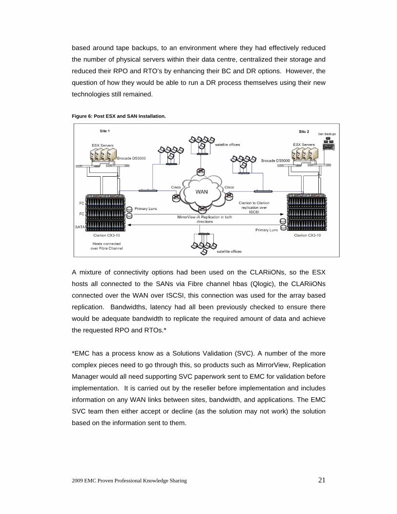
Each SRM session needs to be able to connect to its local storage, but SRM will fail
to see any storage without Solutions Enabler installed.
Figure 11: Configure Array Manager Screen in SRM.

2009 EMC Proven Professional Knowledge Sharing 29
In our case study, the application is SRM and the Storage is an EMC CLARiiON.
Solutions Enabler is downloaded from EMC’s PowerLink site; it’s free, and is installed
onto each Virtual Centre (VC) server. One of the first things to do after installing
SRM is to make sure both SRM servers (installed on each VC server at each site)
can communicate with each other and also the underlying storage.
SRM Storage Prerequisites The following must be in place for SRM to find any LUNs on its local storage array to
protect:
• Healthy storage systems at both Protected and Recovery sites.
• LUNs replicated via Replication product (MirrorView here) to an alternate
array, and the LUNs must be in either a synchronized or Consistent state.
• For MirrorView, Consistency groups in place at the Protected site.
• For MirrorView, Snapshots in place at the Recovery site.
Assuming the storage is healthy and LUNs already replicated some manual
administration then needs to take place:
MirrorView Consistency Groups Figure 12: Consistency groups within Navisphere Manager.
These groups ensure consistent remote copies of data from one or more applications
for disaster recovery, via MirrorView. For example, applications that consist of
databases and Logs which are held on different LUNs require a method to guarantee
transactional integrity between the interrelated LUNs at the alternate site. A good
example of this is Exchange, which would consist of at least a database LUN and
ideally on a separate LUN, the Logs. These LUNs are related, which ever operations

2009 EMC Proven Professional Knowledge Sharing 30
take place for one LUN should also take place for all other related LUNs. Any
synchronisation, updates, promotions, pauses, or splits need to take place across the
entire group of associated LUNs. Putting these LUNs into a MirrorView Consistency
group ensures the LUNs remain in synchronisation. Any operations that would
normally be carried out for a single LUN, would now be carried out on the entire
group, which ensures consistency for all LUNs defined within the group. You could
also put all the Exchange LUNs from multiple storage groups’ within the same
consistency group. Therefore all mirroring operations take place for the entire set.
There are limitations associated with consistency Groups. The limits are based on
the numbers of consistency groups you can create, or the number of LUNs you can
add into the groups. These limits vary between the CLARiiON generations and
FLARE® code versions, and MirrorView types (S or A), (see figures 13 and 14):
Figure 13: Consistency group Limits for the CLARiiON series.
The below figure shows the maximum Consistency Group figures on the CX4 range
running FLARE® code 28.

2009 EMC Proven Professional Knowledge Sharing 31
Figure 14: Consistency group Limits for the CLARiiON CX4 series.
The numbers of consistency groups have increased a great deal on the CX4 series,
but on the CX3 series could still prove a limitation if a large number of LUNs need to
be protected. For example, on a CX3-10 with FLARE 26, running MirrorView/A, you
can create a maximum of eight Consistency groups, and add up to eight LUNs within
each group. That’s 64 LUNs firstly, but also putting eight LUNs into a single
Consistency group may not be the best option.
The purpose of a consistency group is to manage the different LUNs as if a single
entity. The fact the LUNs exist within the same group implies the LUNs all belong to
the same application and therefore require consistent operations. SRM will also not
successfully discover any replicated LUNs (Datastores) on the CLARiiON unless they
are put into a Consistency group, whether the LUNs are related or not. So even if
you want to protect single LUN, it must reside in a Consistency group.
Protecting a large number of LUNs will mean eventually adding unrelated LUNs into
the same consistency groups, which can cause problems regarding replication. If a
single LUN does not replicate for whatever reason, then all LUNs within the group
can go into a fractured state. That makes sense if the LUNs are related (e.g.
Exchange LUNs), but if not, that’s a problem. A single problem affecting a single
LUN can affect all LUNs within the same group. If one LUN stops synchronising, then
all of the LUNs can stop.

2009 EMC Proven Professional Knowledge Sharing 32
You can create a recovery plan for each consistency group within SRM, so it is
possible to either test or failover each individual group separately. That could be
useful for an organization which provides DR services for other organizations, as
long as the maximum number of consistency groups you can create are not the
limiting factor.
SnapView Snapshots Figure 15: Snapshots within the Navisphere® Manager.
Snapshots need to be configured at the recovery site, before initiating any scan from
SRM. The snapshots need to be in place in order for SRM to discover the replicated
LUNs that you want protected.
The figures below (16a and 16b) show an SRM rescan taking place. The
configuration below already had an existing protection group and recovery plan, a
new LUN was added to the array (containing the VMs), and replicated to the DR site.
A Snapshot was then created for the secondary copy for the purposes of SRM, at the
recovery site.
The newly replicated LUNs were added into a consistency group at the protected
site. SRM was then able to successfully pick up the newly mirrored LUNs, and
protect them. The name of the Snapshot must also be in the following format:
“VMWARE_SRM_SNAP_xxxx” where xxx is a unique name given by you (see figure
15).

2009 EMC Proven Professional Knowledge Sharing 33
Figure 16a : Original Datastores in SRM Figure 16b: Scan for new Datastores
(LUNs).
LUN Masking and SRM During a failover, the standby hosts at the DR site need to be able to come online
along with access to the newly promoted mirrored LUNs. For this to work, before any
promotion or DR takes place, the secondary (mirrored) LUNs on the DR array need
to be assigned to a storage group (LUN Masking). The standby/secondary hosts
also need to be members of this group.
Creating and adding members to this group is a manual step, SRM does not put the
secondary LUNs into the storage group. Miss this step, and the failover will not work.
During Mirror promotion, SRM will initiate a rescan within ESX (standby servers) for
new storage, and the new LUNs will not be discovered, due to LUN masking.
Figure 17: Storage Groups (Access Logix) in Navisphere Manager.

2009 EMC Proven Professional Knowledge Sharing 34
SRM will stop at that point. I found this out the hard way! I then added the LUNs into
the storage group manually, and SRM was clever enough to continue from the last
executed command within the Recovery Plan.
The same applies for the Snapshots. When selecting the Test option (Figure 18) in
SRM, the ESX servers will not be able to scan and discover any new storage to
mount (the snapshot), unless the Snapshot and the standby hosts have been
manually added into a storage group at the recovery site.
Figure 18: SRM Test option.
If Testing Just Isn’t Enough Inevitably at the final stages of a project, a test will not be enough for many
customers. They may want more assurance that the solution works, and
understandably so.
Practice also makes perfect, there have been a number of instances of high profile
companies that have suffered from irrecoverable data loss, despite them having “fool
proof” disaster recovery plans in place. The reason for the failure was because
despite the existence of a plan, no one had bothered to have a trial run of the
disaster recovery plan to see whether it actually worked or not. Testing a disaster
recovery plan is as important as formulating it. A number of unforeseen factors may
occur during the actual failover so it’s a chance to really test the procedures.
There is a “Test” option in SRM, however what many customers will probably ask for
(as in this case) is to “Run” SRM (Figure 19), which meant actually failing everything
over.
The suggestion to the end user here was to failover all systems to the alternate site,
and then as part of the test, to run all applications for a week out of the DR site.
Based on the hardware, and bandwidths available between sites, users should see
no difference when accessing the applications from the other site.

2009 EMC Proven Professional Knowledge Sharing 35
Figure 19: SRM DR Failover option.
What are the implications of this? First, it means you’ll actually be carrying out the
DR, not a test. The most important aspect is to make sure the customer has a real
understanding of exactly want is required and what is involved, don’t assume the
customer knows. This may be the first time they’ve used this type of technology;
they may never have gone through any form of DR process before.
Once the customer understands the implications of running a full DR, then perform
some form of risk analysis to highlight any particular issues during a DR. Any
contingency plans should be designed and put in place, and the appropriate
resources made available. Running a DR plan requires full cooperation and
involvement from the customer; it’s not something a consultant just runs. Let’s look
at what we’re trying to achieve:
Objectives of Failover: To failover all replicated applications to the alternate site,
including all infrastructure servers and data and to ensure the disaster recovery plans
within SRM work during a time of crisis.
Success criteria: Accessibility of Infrastructure, recovered servers and applications
from the alternate site within the defined RTO. Recovered data must fall within the
agreed RPO. The customer must have some way of measuring the success or
failure of the process being carried out. Can the users access their applications after
the failover has taken place?
Select the appropriate time for the failover. This entirely depends on the business.
For the case scenario, the weekend in the UK (Saturday and Sunday) were the most
appropriate days, as this period had the least amount of activity.

2009 EMC Proven Professional Knowledge Sharing 36
Make sure all the relevant expertise is on hand to get all the servers and applications
running at the other site, especially if any extra maintenance is required. This
solution delivered a crash consistent solution, not application consistent, so some
manual work may be required in order to recover certain applications.
The administrators and experts within the following areas were on site during the
failover. Additionally an auditor from 3rd party organisation was also present to watch
the entire process.
• Storage /SAN experts.
• Server/VMWare administrators.
• Application specific administrators (e.g. Exchange, SQL).
• Infrastructure (e.g. Active Directory, networking, routers, switches).
Contingency Always have an alternative plan as things can and often do go wrong! The mirrors
had already been previously tested by manually taking Snapshots of the secondary
LUNs. The SRM “Test” was also run before selecting the “Run” option (the actual
failover). Snapshots or clones could also be taken of any primary LUNs, before
initiating fail over. Even if SRM failed to run the Recovery Plan, as long as someone
has thorough knowledge of VMware and the Storage, the LUNs could be failed over
manually, and all the VMs brought online at the secondary hosts. It would just take a
lot longer to recover everything to the alternate site.
SRM displays the recovery procedures within its interface. It can be exported to a
number of formats (web, doc, xls, csv). The procedure then could be run manually if
required, the fact you have a written procedure with the actual sequence of steps is
invaluable. This also serves as part of your DR documentation, and is very easily
updated.

2009 EMC Proven Professional Knowledge Sharing 37
Figure 20: SRM Recovery Plan, and Export option.
No Auto Failback Once failover has completed, if the end user wants to return the data and systems
back to the original site, make them aware that there is no automatic failback
available. In fact, to get the systems back to the original site involves rebuilding the
SRM recovery plans and executing them to failover to the original site so it’s not a
failback, it’s another failover.
SRM uses a small LUN on the array called a Placeholder; this contains the recovery
plans and is held at the recovery site. After running a failover, you need a new
placeholder held at the new recovery site. The protected site and recovery sites will
have changed places after failover so SRM will need to be setup accordingly in order
to fail everything back to the original site.

2009 EMC Proven Professional Knowledge Sharing 38
Figure 21: Before Failover.
Figure 22: After Failover Protected and Recovery sites have changed.

2009 EMC Proven Professional Knowledge Sharing 39
Resynchronisation During a real disaster there will very likely not be any chance of an immediate
failback. If the primary system was completely lost, then new mirrors would have to
be built once the primary array is up and running again.
Here the primary site is still active after failover. SRM’s failover involves promoting
the secondary LUNs at the remote site to Primary LUNs, using in this case
MirrorView/A. Depending on the state of the LUNs and of synchronization
(MirrorView/A) during the promotion, the new Primary LUNs may need to fully
resynchronise with the new secondary LUNs afterwards. This resynchronisation will
need to complete before any failback can take place, so this normally takes time
depending on much data needs to be resynchronized. Also because a number of
LUNs may exist within a consistency group, this could further slow synchronisation
because if one LUN needs to go through a resynchronisation, all of the LUNs within
the Consistency group need to resynchronise (see Consistency groups earlier). In
this case there will be no quick failback. SRM’s protection groups and Recovery
Plans will also need to be rebuilt, along with a new placeholder.
When the Failover (or failback) does finally take place, and the data and systems are
back at their original sites, a complete rebuild of SRM will have to again take place in
order to ensure the systems are protected and ready for failover during a disaster, so
it’s a lot of work.
There is talk of an Auto Failback feature in future a version of SRM, I haven’t seen
this as yet, and I think the functionality of this will depend on the Storage Vendor
underneath and what its capabilities are, but it will be very interesting to see how this
works in future versions.
Suggested Architecture The end user in the case study opted originally to equally balance the number of
Primary and Secondary LUNs at both sites. There are advantages to this. Users are
able to access their systems locally, and failing over an entire site would mean failing
half the systems rather than everything. It does, however, in my opinion lead to a
more complex SRM configuration, particularly if the end user wants to actually test
the recovery procedures by running periodic failovers.

2009 EMC Proven Professional Knowledge Sharing 40
In this particular case it would be better to base all primary LUNs at a single site.
Therefore the SRM protected site is a single site, not both. The recovery site will
also be a single site. Replication will take place in one direction only. This design
would mean the end users would be able to carry out failovers every two months for
example, fairly easily. They could then run all systems out of the Recovery site
(which would become the protected site regarding SRM), after 1 or 2 months, fail the
systems back again, and so forth. It means a much simpler setup regarding the SRM
configuration, and also lets the organization regularly practice their DR processes.
What shall we use for Recovery and when? The Housing Association now had 2 separate SANs at separate sights, and a host of
new DR technologies. The technologies and methods for recovery needed to be
categorised so the customer would know which recovery method would be the most
effective against any given disaster. Some of the new technologies would kick in
automatically if any failures took place, for example the technologies within ESX such
as Vmotion, HA. However some of the array based technologies like SnapView are
either manually launched or scripted unless the customer buys something like
Replication Manager. The most important question now was which weapon to use in
the arsenal and when? At what point do you decide whether you use a mirrored
replica from a different site, or a snapshot, or use the tape backup to restore data.
The answer depends on the situation and type of loss that’s occurred.
Categories types of Failures Here are the types of IT failures that can occur in this organisation:
• Server
• SAN
• Site
*Additional categories for concern within the IT systems would include the
applications, databases, network infrastructure, switches, connectivity, and desktops.
These areas are maintained in-house so we liaised with the relevant teams regarding
the above areas, recovery procedures as well as key personnel and their
responsibilities.

2009 EMC Proven Professional Knowledge Sharing 41
Categorising the technologies implemented and identifying when to use which, or
which the customer prefers to use during different types of failures is important as it
helps explain to the customer what each new and existing technology is capable of
and which is more appropriate during different types of disaster. For example, one
would not use MirrorView to recover from a server failure in this case because each
site has a VMware cluster of 4 nodes. The end user may feel bombarded by
sometimes very similar technologies which do very similar things, it can all become
very confusing, what we don’t want is for this project to just become an exercise in
installing new technologies. Hopefully the end user will become actively engaged
and embrace the new technologies. Figure 23 shows an example of how to
categorise the technologies within this particular scenario, (example of a DR scenario
would be complete site or array failure) additionally whether the technology is part of
ESX or the EMC array. SRM is a special case as it ties the storage to the operating
system, in the case of DR.
Figure 23: Categorise type of Recovery technologies available within the Housing Association.
Prioritising which recovery method to use to combat different kinds of disaster is vital
because you don’t want a customer using a recovery method which isn’t as effective
as an alternate method, or takes longer to recover. Figure 24 lists the types of
disasters the technologies can counter. It’s a question of deciding which of the
Categorise types of Recovery
VMware ESX
EMC Clariion
Tape Backup
MirrorView/A
Vmotion
HA
DRSSnapView
Site Recovery Manager
Raid Protection
Five 9's availabilityCluster

2009 EMC Proven Professional Knowledge Sharing 42
technologies listed in figure 23 would be best to use during the types of disaster
listed in figure 24 below. Would a single technology or combinations be more
effective (for example, using both MirrorView and SnapView to recover)?
Figure 24: Categorise possible IT related failures within the Housing Association.
“What is more important than the technologies and techniques is having a coherent
business continuity plan or BCP. The plan will dictate what tools and methods you
will need to carry it out. What is the bottom-line impact of losing parts of the
business? That will help you select the right response solutions.” 5
5 Planning for the Unforeseen, Publication: Customer Interaction Solutions.
Types of Failures
Server Failure
SAN Failure
Site Failure
Hardware Failure
Hardware Failure
Flood
Fire
Power CutClariion
Fibre or Iscsi switch
Server HBAsApplication
Failure
Lun corruption
Data corruption
Application/Software Failure
Application Crash
User Error
Virus

2009 EMC Proven Professional Knowledge Sharing 43
Conclusion The city of Pittsburgh rolled out VMware Disaster recovery during 2007; they
virtualised 80% of their servers according to network Analyst Alex Musicante. SRM
was later added and Pittsburgh was then able to implement a disaster recovery plan.
Using virtual servers instead of physical servers meant the city were able to set up a
secondary data centre for disaster recovery at approximately 50% of the original
estimated cost. "The virtualization process in general has been very positive for us,"
Alex reported. "It has also allowed us to get rid of some legacy systems and
modernize the network.6”
Adopting so many new technologies at the same time can be a daunting task,
especially for the IT staff that will have to learn and manage it all, but SRM goes
some way to making the management and adoption of DR processes, an easier task,
within a virtualized environment. A lot of DR solutions don’t work simply because the
staff do not understand the processes or have the expertise to be able to carry out
any form of disaster recovery. If the systems take too long to recover, then it defeats
the whole object of having a DR process.
Taking responsibility for the end solution is paramount to the success of any such
project, including continued end user involvement, possibly involving additional
training. Obtaining executive support and getting the support of other managers to
ensure that participants are properly chosen and committed to the program is crucial.
A dedicated team or roles should be created, certainly when dealing with BC and DR
processes there needs to be a chain of command, and an understanding of how and
when the recovery processes should be activated.
SRM goes a long way towards untangling parts of a DR process, and automating
them, certainly within the SME market and public sector organizations, where high
end skills may be limited and DR experience low, this is valuable product. There are
plenty of examples of companies running offsite replication like MirrorView that really
would have no idea what to do in the event of a disaster, even though they have the
technologies in place.
6 VMware Customers Continue Expanding Use of Virtualization to Disaster Recovery, Data Security and Desktop Management – www.VMware.com

2009 EMC Proven Professional Knowledge Sharing 44
References
• VMware Site Recovery Manager with EMC CLARIION CX3 and MirrorView/S,
on Powerlink.
• Steps to setup EMC CLARiiONs for VMware Site Recovery Manager ver. 3
(http://viops.vmware.com/home/docs/DOC-1227).
• Disaster Recovery and Contingency Planning in Extreme Times by George
Fenton.
• Disaster Planning with a Business Continuity Plan by Michael G Perry.
• Disaster Recovery Plans and Systems Essential by Roberta j. Witty, Donna
Scott (Gartner Report).
• RTO’s Role in Recovery Planning by Jim Barnes.
• Downtime and Recovery in Microsoft Exchange Environments by Gary Gysin.
• When Data Protection is Not Enough by Henry Martinez.
• The (Not so) Dark Side of Risk by James G. Callahan.
• Core Principles of BC/DR by Peter R. Laz.
• The Advantages of Data De-duplication for Data Protection by Jedidiah Yueh.
• EMC Celerra VSA and VMware SRM - Complete Setup and Configuration
Guide - Revision 1.0.1.
• SOX: What does it mean for UK Companies? By Adrian Giles.

2009 EMC Proven Professional Knowledge Sharing 45
Biography
Faisal studied Systems Analysis and Design and French at Kingston University,
England, graduating in 1992. As part of his studies, he spent a year in France, at the
Universities of Montpellier and Dijon.
Faisal started out in IT by specializing in operating systems (Novell Netware) and has
been involved in a number of large scale deployments (my certifications include CNI,
MCNE, MCT, MCSE). He gradually began specialising in Storage Area Networking
while working on a project at Data General. He is also an EMC instructor, so has the
luck and opportunity to travel the world delivering EMC courses in English and
French.
He is now working at Magirus UK carrying out pre-sales technical work and
implementations (CLARiiON®, Celerra®, and Centera®). He also mentors
Implementation Engineers for any EMC reseller in the process of becoming Velocity
(previously ASN) accredited, within the EMEA region.
Faisal is married to Ismat, a doctor. They have two children, Laila and Naissir. His
hobbies include snowboarding and long boarding, and trying to teach the kids to do
the same.
He is proud to have achieved a CLARiiON Solutions Implementation Engineer Expert
level certification.
Related Documents