Yabin Dong Reactivity Controlled Compression Ignition (RCCI) Combustion Using Methanol and Diesel in a Single Cylinder Research Engine School of Engineering Thesis submitted for examination for the degree of Master of Science in Technology. Espoo 30.6.2018 Thesis supervisor: Prof. Martti Larmi Thesis advisor: D.Sc. (Tech.) Ossi Kaario

Welcome message from author
This document is posted to help you gain knowledge. Please leave a comment to let me know what you think about it! Share it to your friends and learn new things together.
Transcript

Yabin Dong
Reactivity Controlled CompressionIgnition (RCCI) Combustion UsingMethanol and Diesel in a Single CylinderResearch Engine
School of Engineering
Thesis submitted for examination for the degree of Master ofScience in Technology.Espoo 30.6.2018
Thesis supervisor:
Prof. Martti Larmi
Thesis advisor:
D.Sc. (Tech.) Ossi Kaario
aalto universityschool of engineering
abstract of themaster’s thesis
Author: Yabin Dong
Title: Reactivity Controlled Compression Ignition (RCCI) Combustion UsingMethanol and Diesel in a Single Cylinder Research Engine
Date: 30.6.2018 Language: English Number of pages: 7+59
Department of Mechanical Engineering
Professorship: Martti Larmi Code:
Supervisor: Prof. Martti Larmi
Advisor: D.Sc. (Tech.) Ossi Kaario
Conventional internal combustion engines have severe CO2, NOx and particulatematter (PM) emission problems so that the majority of countries in the worldhave issued regulations to control the emission. Alternative fuels such as naturalgas, methane and ethanol are studied to tackle the problem. Methanol also hasthe potential to reduce CO2, NOx and PM emissions due to lower C/H ratio, localoxygen and high evaporation latent heat. Therefore, methanol, as a fuel, appliedwith advanced combustion technology provides possibilities to solve emissionproblems.
RCCI technology is discovered as an advanced engine technology to reduceNOx emissions as well as fossil fuel utilisation in the future. In the thesis,methanol and diesel are chosen to conduct the RCCI combustion. To reach theRCCI combustion mode, the diesel injection strategy is firstly tested, and theexperiment is divided into two groups based on the diesel injection strategy:split diesel injection and single diesel injection. Within each group, methanolinjection timing, methanol substitution rate (MSR), air mass flow and air intaketemperature are the main parameters.
The results demonstrate the diesel injection strategy has a direct influence onthe combustion characters. RCCI combustion mode can be reached in single andearly diesel injection conditions, while the feature of combustion in split dieselinjection condition is dominant by the pilot diesel fuel showing dual fuel or dieselcombustion characters. Single diesel injection also reduces the NOx emissions.In both experiment groups, air intake temperature significantly active the fuel.Besides, in the single diesel injection group, each particular MSR has a preciseand narrow diesel injection operation window.
Keywords: methanol, RCCI, reactivity stratification, injection strategy
Yabin Dong
iii
PrefaceThe master thesis was conducted in the Internal Combustion Engine Laboratory,Aalto University. The thesis is funded by the European Union Project, Hercules2,and a minor funding granted by Henry Ford Foundation. I am grateful for all theorganisations involved in the project providing research resources, facilities and fi-nancial support to complete the thesis.
I would like to express my sincere appreciation to my supervisor Professor MarttiLarmi and Advisor D.Sc. (Tech) Ossi Kaario for all the knowledge and expertisethey offered. I have learned plenty of knowledge not only about combustion sciencebut also practical research skills.
I would also like to take this opportunity to thank research engineer Olli Ranta andOtto Blomstedt. Without their excellent technical support and patient instruction,I cannot finish the thesis experiment. Also, many thanks to my colleges Ari Ain-salo, Janak Aryal, Qiang Cheng and Zeeshan Ahamed who inspire me when I faceproblems. The working environment of the laboratory that provides pure academicatmosphere deserves all my respects.
Finally, all the words cannot express my great appreciation to my family and closefriends for consistently supporting me during my study period in Europe. A par-ticular honour belongs to my parents for all the understanding and support in myentire life.
Otaniemi, June 2018
Yabin Dong
iv
ContentsAbstract ii
Preface iii
Contents iv
Nomenclature vi
1 Introduction 1
2 Background 32.1 Methanol . . . . . . . . . . . . . . . . . . . . . . . . . . . . . . . . . 32.2 Methanol Application in Transport Sector . . . . . . . . . . . . . . . 72.3 Combustion . . . . . . . . . . . . . . . . . . . . . . . . . . . . . . . . 8
2.3.1 Premixed Combustion . . . . . . . . . . . . . . . . . . . . . . 112.3.2 Non-premixed Combustion . . . . . . . . . . . . . . . . . . . . 122.3.3 Dual Fuel Combustion . . . . . . . . . . . . . . . . . . . . . . 142.3.4 Homogeneous Charge Compression Ignition Combustion (HCCI) 16
2.4 Reactivity Controlled Compression Ignition (RCCI) . . . . . . . . . . 172.4.1 Influence of Parameters on RCCI . . . . . . . . . . . . . . . . 182.4.2 Limiting Factors of RCCI . . . . . . . . . . . . . . . . . . . . 222.4.3 Emission Characters of RCCI . . . . . . . . . . . . . . . . . . 23
3 Research Methodology 263.1 LEO1 Engine Setup . . . . . . . . . . . . . . . . . . . . . . . . . . . . 26
3.1.1 Fuel System . . . . . . . . . . . . . . . . . . . . . . . . . . . . 273.1.2 Air Feeding, Exhaust and EHVA system . . . . . . . . . . . . 29
3.2 GT-SUITE Simulation of Methanol Evaporation . . . . . . . . . . . . 303.3 LEO1 Experimental Methods . . . . . . . . . . . . . . . . . . . . . . 31
3.3.1 Test Methods . . . . . . . . . . . . . . . . . . . . . . . . . . . 313.3.2 Parameters Setup and Test Matrix . . . . . . . . . . . . . . . 32
3.4 Data Processing . . . . . . . . . . . . . . . . . . . . . . . . . . . . . . 353.4.1 Fuel Related Parameters and Calculations . . . . . . . . . . . 353.4.2 Cylinder Temperature, Pressure and Heat Release Calculation 36
4 Results and Discussion 384.1 GT-SUITE Results of Methanol Evaporation . . . . . . . . . . . . . . 384.2 Split Diesel Injection Experiment Results . . . . . . . . . . . . . . . . 39
4.2.1 Case 1: Effects of Methanol Injection Timing . . . . . . . . . 394.2.2 Case 2: Effects of Air Mass Flow (φ) . . . . . . . . . . . . . . 404.2.3 Case 3: Effects of Air Mass Flow at 70C . . . . . . . . . . . . 424.2.4 Case 4: Effects of MSR at different Engine Load . . . . . . . . 43
4.3 Single Diesel Injection Event Experiment Results . . . . . . . . . . . 444.3.1 Case 5: Effects of Methanol Injection Timing . . . . . . . . . 44

v
4.3.2 Case 6: Effects of Air Intake Temperature . . . . . . . . . . . 454.3.3 Case 7: Effects of Diesel Injection Timing for Different MSR . 46
4.4 Results Summary . . . . . . . . . . . . . . . . . . . . . . . . . . . . . 494.4.1 Combustion Characters Comparison . . . . . . . . . . . . . . 494.4.2 Combustion Temperature and NOx Emissions . . . . . . . . . 514.4.3 Fuel Reactivity . . . . . . . . . . . . . . . . . . . . . . . . . . 52
5 Conclusions 54
6 Future Work 56
References 57
vi
Nomenclature
AbbreviationsAFR Air fuel ratioAIT Air intake temperatureAMF Air mass flowASI After start of injectionbioDME Bio-Dimethyl etherBTDC Before top dead centreCA5 Crank angle for 5% heat releasesCA50 Crank angle for 50% heat releasesCI Compression ignition engineDI Direct injectionDICI Direct injection compression ignitionDIT Diesel injection timingDSR Diesel substitution ratioEGR Exhaust gas recirculatingEHVA Electrohydraulic valve actuatorEISFC Effective indicated specific fuel consumptionEV Electric vehicleFFV Flexible fuel vehicleHCCI Homogeneous charge compression ignitionHRR Heat release rateHTHR High temperature heat releaseHVO Hydrotrated vegetable oilITE Indicate thermal efficiencyktoe Thousand tons of oil equivalentLHV Lower heating valueLTHR Low temperature heat releaseMIT Methanol injection timingMSR Methanol substitution ratioNG Natural gasNTC Negative temperature coefficientPAH Polycyclic aromatic hydrocarbonsPFI Port fuel injectionPM Particulate matterPRF Primary reference fuelQHR Cumulative heat releaseRCCI Reactivity controlled compression ignitionRI Ringing intensityRON Research octane numberSCR Selective catalytic reductionSI Spark ignitionTDC Top dead centre
vii
Symbolsλ Lambdaφ Equivalent ratioCvff Coefficient of methanol vaporisationLgasoline Latent heat of gasoline vaporisationLmethanol Latent heat of methanol vaporisationγ Ratio of specific heatθ Crank anglemf Fuel mass flowE Energy flowC Degree Celsius
Chemical CompoundsCH3OH MethanolCH3CH2OH EthanolCH4 MethaneCO Carbon monoxideCO2 Carbon dioxideH2 HydrogenH2O WaterNO Nitric oxideNO2 Nitrogen oxideNOx Nitrogen oxidesO2 OxygenSOx Sulphur oxides
1
1 IntroductionEnvironment issues including air pollution, water pollution, fossil fuels utilisationand waste of natural resources are threatening the ecological environment of theearth. Energy-related activities have concerned the public because they generatea considerable amount of CO2, SOx, NOx and particulate matters (PM). Energysystem can be divided into four sectors: industry, resident, transportation and otherservice sectors. Due to the high energy intensity, transportation energy utilisationhas attracted researchers attention. Most importantly, diesel, gasoline and otheroil products accounted for 92% of total energy consumption in transport sector [1].Therefore, advanced technologies must be implemented in the transportation sectorto reduce oil products consumption and carbon emissions.
Using alternative fuels such as bio-diesel, hydrotreated vegetable oil (HVO), bio-dimethyl ether (bioDME), ethanol (CH3CH2OH) and methanol (CH3OH) can be asolution to mitigate CO2 emissions. Bio-diesel is derived from biomass and it canplay an essential role in futures’ carbon-neutral energy system; HVO, as a drop-infuel, is regarded as the most prospective alternative fuel and has already dominatedthe renewable fuel market in Finland; BioDME also attracts people’s attention, andthe Volvo group has developed bioDME trucks [2]; Besides, E85 which contains 85%ethanol and 15% gasoline is widely used in flexible fuel vehicles (FFV). Due to simi-lar properties to ethanol, methanol also has promising prospects as a fuel. However,all the alternative fuels are not the same as diesel or gasoline regarding physical andchemical properties, which brings limitations when using renewable fuels. Therefore,multiple solutions are needed to tackle problems in the transport sector.
Advanced power and combustion technologies also provide alternative approaches toreduce emissions. Electric vehicles (EV) can effectively reduce CO2, NOx, SOx andparticulate matters at the local level. The market share of EV has been rising signif-icantly in recent years. However, EV cannot adapt to heavy load off-road conditionswhere internal combustion engine still dominates. Internal combustion engines arestill widely used in the marine sector and the agricultural sector, but emission prob-lems must be diminished. Dual fuel combustion technology uses two fuels in theone engine which reduces soot and NOx emissions. Besides, an advanced internalcombustion engine technology, homogeneous charge compression ignition (HCCI) isdeveloped. HCCI is a low temperature combustion technology combining the charac-ters of compression ignition engines (CI) and spark ignition engines (SI). Accordingto experiments, it achieves extremely low NOx emission [26]. Reactivity controlledcompression ignition combustion (RCCI) is a modified technology based on HCCItechnology, which uses two reactivity level fuels and improves the controllability ofcombustion phase in HCCI [30]. RCCI significantly strengthens engine combustionperformance in terms of NOx emissions and thermal efficiency. It is also flexibleto select fuels such as gasoline/diesel, Alkane/diesel and alcohol/diesel. However,more precise injection time control, the ratio of two fuel and other aspects need tobe explored.
2
This thesis focuses on RCCI combustion using methanol and diesel in a single cylin-der research engine LEO1. The majority research method is the LEO1 experiment,and it is supported by a GT-SUITE simulation. In the first stage, GT-SUITE isused to model the methanol evaporation and how it affects in-cylinder tempera-ture. In the second stage, methanol/diesel are tested on LEO1 research engine. Themethanol injection concept is port injection into the intake manifold. Methanol in-jection event is during the air intake stroke to create the homogeneous mixture, whilediesel is injected around 20 to 50 degrees before top dead centre (TDC) dependingon different combustion conditions. The air mass flow, air intake temperature, thesubstitution of energy from methanol, methanol injection timing, diesel injectionevents and diesel injection timing are studied.
The primary goals of this thesis are:
• Understand the principle and current research status of RCCI technology
• Study the properties of methanol and how methanol vaporisation affects in-cylinder temperature by GT-SUITE simulation
• Study the influence of multiple parameters on the RCCI combustion throughLEO1 experiment. Specifically, study the influence of air mass flow ( or φ)and air intake temperature on the RCCI combustion; study the methanol sub-stitution rate and methanol injection timing influence on the methanol/dieselRCCI combustion; investigate diesel injection strategy, diesel injection timingimpacts to the RCCI combustion; Study NOx emissions
• Understand the RCCI combustion characters and suggest promising workingconditions for methanol/diesel RCCI combustion in middle load high speedengines
3
2 Background
2.1 Methanol
Methanol draws researchers’ attention in recent years owing to its combustion prop-erties and low emission characters. It has good prospects to be a main fuel forvehicles. Methanol is the simplest alcohol, and it is light, colourless, with alco-hol odour and flammable. Besides, it should be noticed that methanol is highlytoxic: only ten mL would cause permanent blindness [5]. In 2015, global demandfor methanol was 70 million metric tons in all industries. Over 90 methanol plantsdistribute in all over the world with 110 million metric tons capacity to meet theconsiderable amount of methanol demand [6].
The corrosion properties of methanol should be noticed because it affects the ma-terials choice of related equipment. Specifically, methanol is significantly corrosiveto aluminium, and there are two mechanisms for aluminium corrosion. Firstly,methanol can react with aluminium oxide (Al2O3) which usually acts as the coatingto protect aluminium. Secondly, methanol can oxidise aluminium directly. The tworeactions are shown in reaction (a) and (b), respectively.
2CH3OH + Al2O3 → 2Al(OCH3)3 + 3H2O (a)CH3OH + 3Al → 2Al(OCH3)3 + 3H2 (b)
During the thesis experiment, the methanol injector was plugged after three weeks.The main metal material of equipment is stainless steel, but the fuel filter is madefrom aluminium. The possible reason is that corroded metal residues block themethanol injector.
The widely used method to produce methanol is synthesis via syngas (CO2 andH2), and it has three processes: synthesis gas preparation, methanol synthesis andmethanol purification [7]. Syngas can be produced from fossil resources such asnatural gas and coal. Steam reforming (Reaction (c) and water gas shift (Reaction(d)) are the primary chemical reactions to produce syngas from natural gas. Otherthan steam reforming, partial oxidation and dry reforming are different approachesto produce natural gas derived syngas [8]. Besides, coal is another vital resourceto general synthesis gas that contains partial oxidation (Reaction (e)) and watergas shift reaction (Reaction (d)). This process is also known as coal gasification.In addition, biomass, as a renewable raw material, is utilised to produce methanolas well, and similar to coal, gasification approach is mainly used in industrial levelbiomass for syngas conversion. The challenge in biomass to syngas conversion isthe tar content, but usually, it can be tackled by choosing appropriate operatingparameters for certain biomass. Although biomass derived synthesis still remains insmall scale, it provides a sustainable approach to produce syngas and subsequentlyto methanol.
2CH4 + 2H2O 2CO + 6H2 (c)CO + H2O CO2 + H2 (d)
4
C + 1/2O2 CO2 + H2 (e)
The second step is the methanol synthesis including three chemical reactions. Re-action (h) is the reverse of water gas shift reaction and combine with Reaction (f)being the overall methanol synthesis Reaction (g). Finally, water, the main impurityis removed by heating up the liquid products [7].
CO + 2H2 CH3OH (f)CO2 + 3H2 CH3OH + H2O (g)CO2 + H2 CO + H2O (h)
Methanol is widely used in industries, especially in manufacturing other chemicalssuch as biodiesel, plastics, paints and textiles. It is a raw material for catalysedtransesterification reacts to generate biodiesel (Reaction (i)), and it is a denaturingagent for ethanol that can be further used as a solvent [5],[9].
Fatty acid(R1COOH) + methanol Ester(R1COOR) + H2O (i)
Methanol is also an alternative fuel in internal combustion engines. The comparisonamong diesel, gasoline, ethanol and methanol are shown in Table 1. Each propertyis analysed in the following paragraphs.
Table 1: Fuel Properties Comparison [5],[10–14]Diesel Gasoline Methanol Ethanol
Formula C12-C20 C4-C12 CH3OH CH3CH2OHMolecular Weight [g/mol] 150-250 60-150 32 46Composition [%]
Carbon 86.5 86.5 38 52Hydrogen 13.5 13.5 12 13Oxygen 0 0 50 35
C/H ratio 6.41 6.41 3.17 4Cetane Number min 51 — 3-5 11Octane Number (RON) — min 95 108 109Flash Point [C] 55 40 11 17auto-ignition Temperature [C] 250 300 470 363Flammability [Volume%]
Lower limit 0.6 0.6 7 3.5Higher limit 7.5 8 36 15
Stoichiometric AFR 14.5 14.7 6.4 8.9LHV [MJ/kg] 43 42.7 20.27 26Density at 15C [kg/m3] 820-845 720-775 790 790Viscosity at 25C [mPa.s] 3.35 0.5-0.6 0.544 1.074Heat of Vaporisation [kJ/kg] 225-280 275-365 1155 904
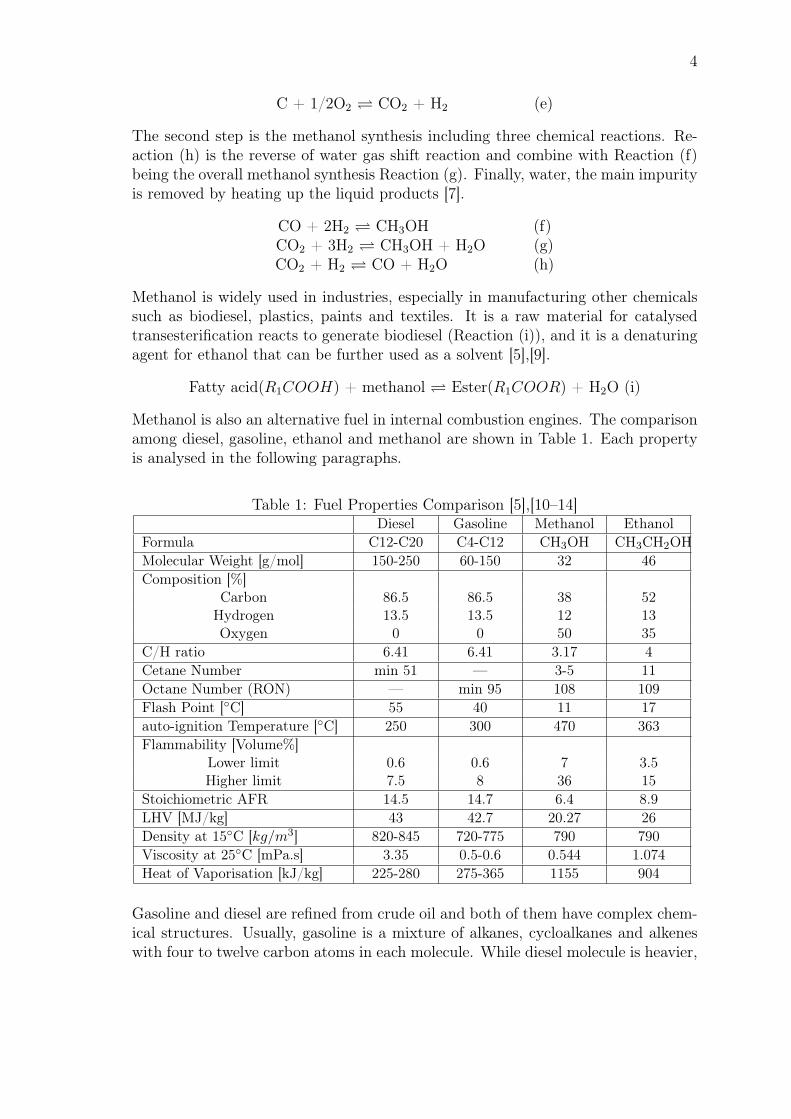
Gasoline and diesel are refined from crude oil and both of them have complex chem-ical structures. Usually, gasoline is a mixture of alkanes, cycloalkanes and alkeneswith four to twelve carbon atoms in each molecule. While diesel molecule is heavier,
5
with twelve to twenty carbon atoms in single diesel molecule, and it is mixed bysaturated hydrocarbons such as alkane and aromatic hydrocarbons, alkylbenzenes.Fig.1 indicates the chemical structure of basic hydrocarbons. In the fuel combustionprocess, the long chain molecule of gasoline and diesel is firstly cracked into smallalkanes and other hydrocarbons. Then the simple radicals are further converted toCO2 and H2O.
Figure 1: Chemical Structure of Alkane, Alkene, Alkine and Aromatics [15]
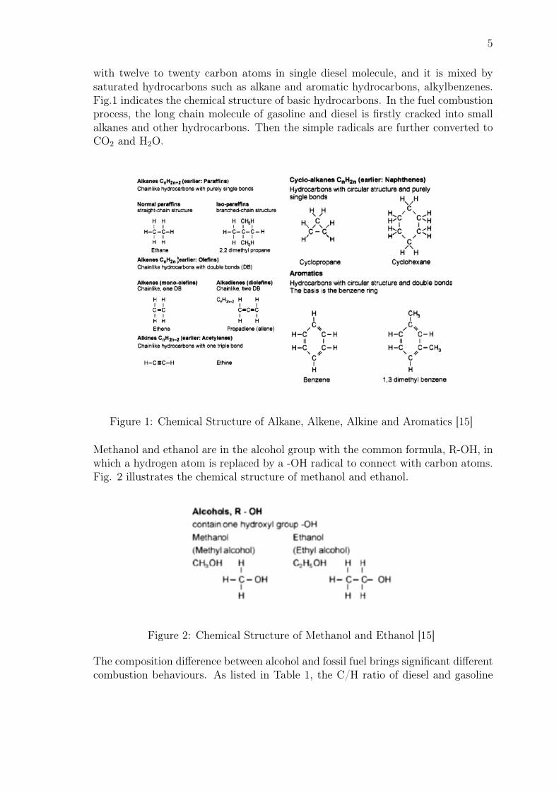
Methanol and ethanol are in the alcohol group with the common formula, R-OH, inwhich a hydrogen atom is replaced by a -OH radical to connect with carbon atoms.Fig. 2 illustrates the chemical structure of methanol and ethanol.
Figure 2: Chemical Structure of Methanol and Ethanol [15]
The composition difference between alcohol and fossil fuel brings significant differentcombustion behaviours. As listed in Table 1, the C/H ratio of diesel and gasoline
6
is around 6.41, while the C/H ratio for methanol and ethanol are 3.17 and 4, re-spectively. C/H ratio acts as an effective emission indicator, and a higher C/H ratiomeans higher CO2 emissions. The C/H ratio of methanol is around fifty percentlower than that of diesel and therefore, methanol does benefit the environment fromcarbon emission’s point of view. Besides, the oxygen content of alcohol fuel canreduce PM emissions, since local oxygen provides sufficient oxidiser. While, theslightly higher NOx emission is observed with the present of oxygen [16].
Cetane number reflects the ignition properties of CI fuel, and higher cetane numberindicates the fuel is easier to be compression ignited. There are two references todetermine the cetane number of a certain fuel, n-hexadecane (C16H34) with cetanenumber 100 and α-methyl naphthalene (C11H10) with cetane number 0 [15]. Ac-cording to the European standard, the minimum cetane number of diesel fuel is 51.By contrast, the cetane number of methanol is less than 5, which brings the chal-lenge of compression ignition. Octane number indicates the knocking resistance ofSI fuels. Similar to cetane number, the octane number of a fuel refers to ISO-octane(C8H18) that octane number is 100 and n-heptane (C7H16) that octane number is0. Knocking is a phenomenon that combustion of the fuel occurs before flame frontreach that location. It causes the unbalanced pressure distribution in the cylinderthat is harmful to the engine. The octane number of methanol is 108, so it hasdesired knocking resistance.
Auto-ignition temperature is also a crucial property of CI fuel due to the ignitionprinciple of the diesel engine. Unlike SI engine which has a spark plug to ignite thefuel, the ignition of CI engine is depended on the in-cylinder pressure and tempera-ture. The auto-ignition temperature of methanol is 470C, but diesel can burn with-out ignitions resources when the temperature reaches 250C. It brings the challengeto ignite the methanol and usually a higher compression ratio or ignite improver areused to tackle the problem.
LHV indicates the energy content of the fuel. It is clear that both diesel and gasolinehave much high energy content than alcohol fuels (Table 1). It means producingthe same amount of power, much more alcohol fuels are needed if the efficiency isthe same. Besides, it should notice that the latent heat of methanol vaporisationis significantly higher than that of diesel. The fuels have to evaporate to the gasphase to be burned, and inevitably the methanol evaporation brings strong coolingeffects to the cylinder leading to cylinder peak pressure drop. The cooling effect ofmethanol vaporisation makes methanol ignition even more difficult. In the thesis,methanol cooling effect is modelled in GT-SUITE and the results are shown in chap-ter 4. However, the benefit of methanol cooling effect is that the low temperaturecan result in low NOx emissions. Also, the cooling process increases the engine ef-ficiency, since the engine components are cooling down and it reduces heat losses [13].
To summarise, methanol benefits the combustion because it reduces the emissions;however, the ignition difficulty and lower energy content negatively affect the com-
7
bustion. Therefore, the utilisation of methanol as a fuel needs to be further explored.
2.2 Methanol Application in Transport Sector
Methanol has received more attention as an alternative fuel in both automotive in-dustry and marine industry. According to EN 228 standard, the limitation of theoxygen content of the transport fuel is 2.7% (m/m) corresponding to 5.4% (m/m)methanol. Additionally, EN 228 specified only 3% (V/V) methanol can be added andstabilising agents is needed. For light-duty vehicles, a low percentage of methanolcan be blended with gasoline in the conventional SI engines. The application ofmethanol in heavy-duty vehicles such as trucks is still being researched. Regardingmarine application, methanol is a promising and safe alternative fuel in ships toreduce NOx, SOx and PM. MAN Group and Wärtsilä have already developed dualfuel marine engines using methanol.
One desirable methanol application in the automotive industry is methanol fuel cell.The Danish company, SerEnergy has developed the methanol fuel cell vehicle withthe range up to 800 km within one tank methanol. SerEnergy developed the first gen-eration Reformed Methanol Fuel Cell (RMFC) on Fiat 500 platform, and the latestRMFC is based on Nissan e-NV200. The Nissan e-NV200 RMFC vehicle enables upto 800 km which can satisfy the utilisation such as urban taxis and delivery van [17].
To understand the potential of methanol in the marine sector, a methanol marketinvestigation and application research, Sustainable Marine Methanol (SUMMETH),has been conducting in Sweden and Finland, carried on by SSPA Sweden, Scan-diNAOS, Lund University, VTT Technical Research Centre of Finland etc. Theproject attempts to investigate methanol market in Nordic countries and to developadvanced methanol engines. Based on their study of DICI Diesel engine, DICI Dieselengine with SCR, PFI-SI Lean Burn engine, etc., they conclude methanol can havea promising future, but the modification of engines is inevitable. More specific, de-spite most of the current methanol engines are robust, none of the engine modelsis as rugged as diesel engines. Particularly, in-cylinder corrosion is revealed in thepremixed engine types such as PFI-SI engine, if the engine is not warming up prop-erly [18].
While most of the current methanol engines are amended from HFO/diesel/gas dual-fuel engines, a few numbers of engines are available for methanol retrofit. Specif-ically, fuel tanks, piping and bunker systems need to be modified. For instance,boilers and fuel separators are necessary for HFO-engine ships, but they are notrequired when methanol is the primary fuel. MAN Group and Wärtsilä developedmethanol retrofit solutions for marine engines that are under operation.
In 2016, seven ocean vessels equipped with B&W ME-LGI 2-stroke dual fuel enginestart operating. The engine is developed by MAN Group and it can run by methanol,fuel oil, marine diesel oil or gas oil. Fig.3 shows the overview of the ME-LGI engine
8
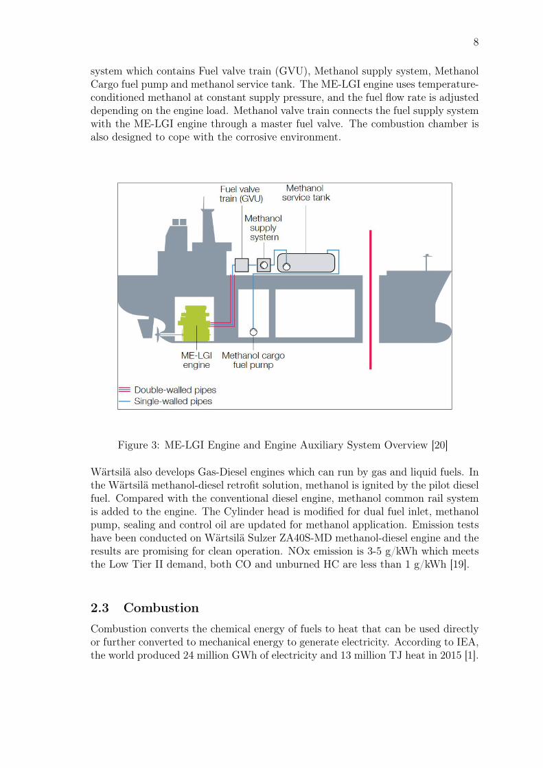
system which contains Fuel valve train (GVU), Methanol supply system, MethanolCargo fuel pump and methanol service tank. The ME-LGI engine uses temperature-conditioned methanol at constant supply pressure, and the fuel flow rate is adjusteddepending on the engine load. Methanol valve train connects the fuel supply systemwith the ME-LGI engine through a master fuel valve. The combustion chamber isalso designed to cope with the corrosive environment.
Figure 3: ME-LGI Engine and Engine Auxiliary System Overview [20]
Wärtsilä also develops Gas-Diesel engines which can run by gas and liquid fuels. Inthe Wärtsilä methanol-diesel retrofit solution, methanol is ignited by the pilot dieselfuel. Compared with the conventional diesel engine, methanol common rail systemis added to the engine. The Cylinder head is modified for dual fuel inlet, methanolpump, sealing and control oil are updated for methanol application. Emission testshave been conducted on Wärtsilä Sulzer ZA40S-MD methanol-diesel engine and theresults are promising for clean operation. NOx emission is 3-5 g/kWh which meetsthe Low Tier II demand, both CO and unburned HC are less than 1 g/kWh [19].
2.3 Combustion
Combustion converts the chemical energy of fuels to heat that can be used directlyor further converted to mechanical energy to generate electricity. According to IEA,the world produced 24 million GWh of electricity and 13 million TJ heat in 2015 [1].
9
68% of power and 96% of heat is from coal, natural gas, oil and biomass which needto be burned to generate electricity and heat. Thus, combustion is still the majorityapproach to utilise energy.
Internal combustion engine outputs mechanical power by extracting energy in fuelsvia combustion reaction in the cylinders. Fuels are burned in the combustion cham-bers to generate high temperature and high pressure gas which delivers power to thepiston. This process is done in the power stroke of a typical 4-stroke piston enginecombining with air intake stroke, compression stroke and exhaust stroke to completean engine cycle. Based on the principle of ignition, typical internal combustion en-gines are divided into compression ignition engine and spark ignition engine. Thedetails of CI engine and SI engine are introduced in the following sections.
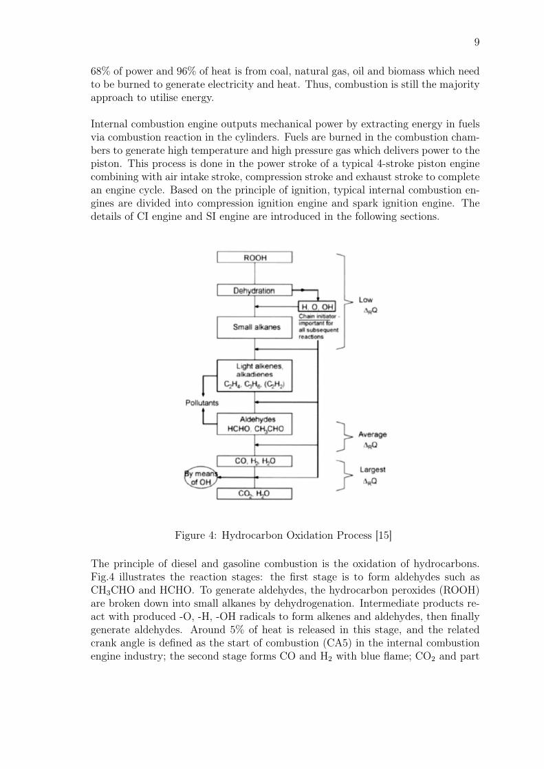
Figure 4: Hydrocarbon Oxidation Process [15]
The principle of diesel and gasoline combustion is the oxidation of hydrocarbons.Fig.4 illustrates the reaction stages: the first stage is to form aldehydes such asCH3CHO and HCHO. To generate aldehydes, the hydrocarbon peroxides (ROOH)are broken down into small alkanes by dehydrogenation. Intermediate products re-act with produced -O, -H, -OH radicals to form alkenes and aldehydes, then finallygenerate aldehydes. Around 5% of heat is released in this stage, and the relatedcrank angle is defined as the start of combustion (CA5) in the internal combustionengine industry; the second stage forms CO and H2 with blue flame; CO2 and part
10
of H2O are ultimately generated in the final stage. Most heat is released in the thirdstage, which leads to the significant temperature rise.
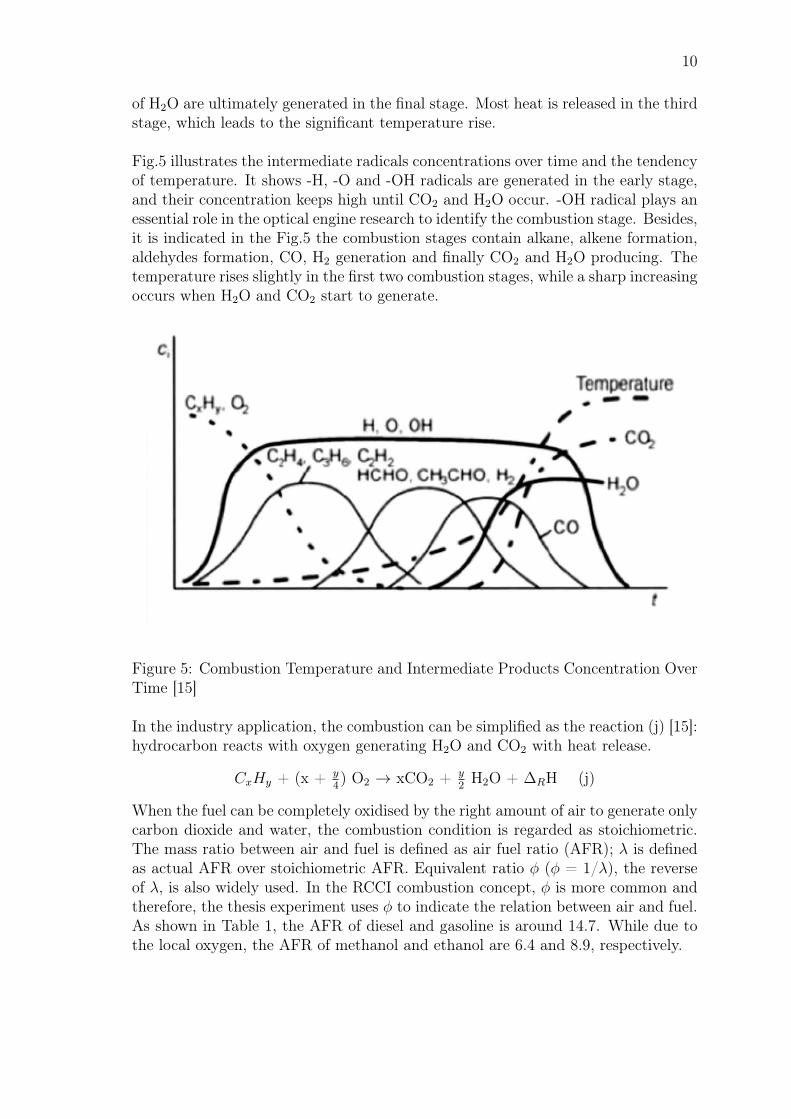
Fig.5 illustrates the intermediate radicals concentrations over time and the tendencyof temperature. It shows -H, -O and -OH radicals are generated in the early stage,and their concentration keeps high until CO2 and H2O occur. -OH radical plays anessential role in the optical engine research to identify the combustion stage. Besides,it is indicated in the Fig.5 the combustion stages contain alkane, alkene formation,aldehydes formation, CO, H2 generation and finally CO2 and H2O producing. Thetemperature rises slightly in the first two combustion stages, while a sharp increasingoccurs when H2O and CO2 start to generate.
Figure 5: Combustion Temperature and Intermediate Products Concentration OverTime [15]
In the industry application, the combustion can be simplified as the reaction (j) [15]:hydrocarbon reacts with oxygen generating H2O and CO2 with heat release.
CxHy + (x + y4) O2 → xCO2 + y
2H2O + ∆RH (j)
When the fuel can be completely oxidised by the right amount of air to generate onlycarbon dioxide and water, the combustion condition is regarded as stoichiometric.The mass ratio between air and fuel is defined as air fuel ratio (AFR); λ is definedas actual AFR over stoichiometric AFR. Equivalent ratio φ (φ = 1/λ), the reverseof λ, is also widely used. In the RCCI combustion concept, φ is more common andtherefore, the thesis experiment uses φ to indicate the relation between air and fuel.As shown in Table 1, the AFR of diesel and gasoline is around 14.7. While due tothe local oxygen, the AFR of methanol and ethanol are 6.4 and 8.9, respectively.
11
AFR =mair
mfuel
(1)
λ =AFRreal
AFRstoichiometric
(2)
λ has strong influences on the internal combustion engines, especially on soot andNOx formation. λ greater than 1 is the lean condition while λ smaller than 1 is therich condition. In diesel engine, soot is likely to form in very rich conditions, whileNOx generates in relatively lean conditions. However, in terms of NOx formation,despite λ affects NOx generation, the NOx is the most sensitive to temperature.In general, diesel engine works in lean conditions and λ can even reach 5. Gasolineengine, as a premixed combustion engine, works in around stoichiometric conditions.However, considering the efficiency of three-way catalyst for exhaust gas treatment,SI engines usually operate under slight lean conditions.
2.3.1 Premixed Combustion
In premixed combustion mode, air and fuel are mixed in advance to create homo-geneous conditions before ignition. Theoretically, premixed combustion presentsstoichiometric (λ=1) air-fuel ratio conditions. In practical, lambda is slightly be-low or over 1 depending on operation conditions. Premixed combustion is inher-ently exothermic radical reactions, and once ignited, the combustion can be self-maintained by the released heat. The premixed combustion starts from the igni-tions source and it develops via flame front propagation. The chemical reactionsoccur at the flame front and it separates burned and unburned fuels. The speed offlame front propagation is known as flame speed which is dependent on the reac-tion environment and reaction rate of reactants [21]. It reflects the speed of flamedevelopment, and usually, a laminar flame has the velocity between 0.5-2 m/s. Dueto the movement of engine, laminar flame barely occurs in the internal combustionengines. While turbulent premixed flame is usually happening in the engines, whichcan reach the velocity of 20-25 m/s [22]. Turbulent premixed combustion is relatedto the many variables such as swirl, temperature and density.
The combustion in gasoline engines is premixed turbulent combustion. The fuel andair mixture is ignited at stoichiometric conditions by the spark plug followed by theflame front propagation, and it extinguishes when reaches the wall. Gasoline enginehas intake, compression, combustion and exhaust strokes. The fuel is injected intothe intake manifold with air or directly injected (DI) into the cylinder in the intakestroke. At the end of compression stroke, the spark plug ignites fuel-air mixture anddeliver power in the power stroke
Knocking is one of the abnormal combustion phenomenon related to SI engines. Ifthe temperature and pressure of the end gas exceed the auto-ignition limitations,
12
the remaining fuel in the end gas will burn before the flame propagation reaches thelocation [21]. This phenomenon is regarded as engine knocking. It leads to localpressure and temperature rising, which resulting in in-cylinder pressure fluctuating.The slight knock leads to noises of engines and severe knock can damage the enginecomponents.
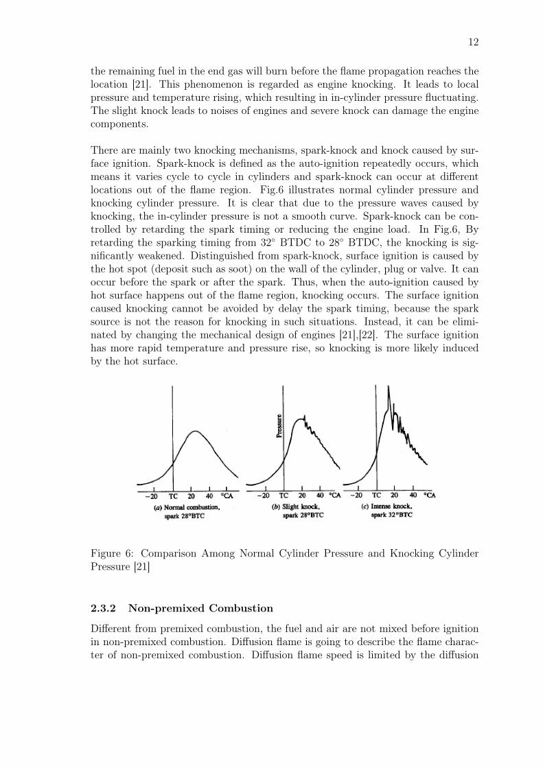
There are mainly two knocking mechanisms, spark-knock and knock caused by sur-face ignition. Spark-knock is defined as the auto-ignition repeatedly occurs, whichmeans it varies cycle to cycle in cylinders and spark-knock can occur at differentlocations out of the flame region. Fig.6 illustrates normal cylinder pressure andknocking cylinder pressure. It is clear that due to the pressure waves caused byknocking, the in-cylinder pressure is not a smooth curve. Spark-knock can be con-trolled by retarding the spark timing or reducing the engine load. In Fig.6, Byretarding the sparking timing from 32 BTDC to 28 BTDC, the knocking is sig-nificantly weakened. Distinguished from spark-knock, surface ignition is caused bythe hot spot (deposit such as soot) on the wall of the cylinder, plug or valve. It canoccur before the spark or after the spark. Thus, when the auto-ignition caused byhot surface happens out of the flame region, knocking occurs. The surface ignitioncaused knocking cannot be avoided by delay the spark timing, because the sparksource is not the reason for knocking in such situations. Instead, it can be elimi-nated by changing the mechanical design of engines [21],[22]. The surface ignitionhas more rapid temperature and pressure rise, so knocking is more likely inducedby the hot surface.
Figure 6: Comparison Among Normal Cylinder Pressure and Knocking CylinderPressure [21]
2.3.2 Non-premixed Combustion
Different from premixed combustion, the fuel and air are not mixed before ignitionin non-premixed combustion. Diffusion flame is going to describe the flame charac-ter of non-premixed combustion. Diffusion flame speed is limited by the diffusion
13
rate which includes fuel penetration, evaporation and mixing with air. Therefore,diffusion flame is slower than premixed flame.
The diesel fuel continuously mixes with air after injected into the combustion cham-ber. The mixing process occurs at the surface of diesel jet where the combustion ispremixed combustion. Diesel combustion tends to generate more soot because thecentre of the fuel region has low local λ resulting in incomplete combustion. Owingto the high temperature, the soot becomes incandescent and radiates visible yellowlight. Besides, more NOx is formed due to the high combustion temperature. Thus,because of this characters, diesel combustion causes serious environmental problems.
In diesel engine, the fuel is injected at the end of compression stroke close to TDCwhen the temperature and pressure reach the auto-ignition conditions of diesel. Dueto the ignition principle, diesel engine is also named as compression ignition engine.Since the diesel is injected close to the TDC, there is no risk of knocking in standarddiesel engines. Hence, the diesel engine can reach higher compression ratio leadingto higher efficiency. However, as mentioned before, high combustion temperaturebrings severe NOx and soot emission problems in diesel engine. Principally, com-bustion in diesel engine is divided into four main phases: ignition delay, premixedcombustion, diffusion combustion and late combustion.
Ignition delay is an important indicator for diesel combustion. It is defined as thetime interval between the start of fuel injection and the start of ignition [21]. Theignition delay is due to the physical and chemical changes: on the one hand, theliquid fuel experiences atomisation and vaporisation; on the other hand, as analysedin section 2.2, the chemical process starts with long diesel molecular absorbs heatand crank into short chains, which prepares for completed combustion.
Premixed combustion is following the ignition delay, and the in-cylinder tempera-ture has reached the auto-ignition temperature of diesel at this moment. Premixedcombustion occurs leading to rapid heat release. However, the premixed combustionphase only lasts an around 2-3 crank angles.
Diffusion combustion is known as mixing-controlled-burn [23] because this phaseis controlled by the in-cylinder air and fuel mixing. According to John E. Dec’sstudy [23], the soot concentration is becoming higher and the size of soot particlesare larger in this phase. Besides, the fuel atomisation and evaporation process con-tinue in this phase.
Late combustion phase occurs when temperature and oxygen concentration is low.It takes place at later expansion stroke with lower heat release rate. The heat releaseis from unburned fuel or soot burning in this process. As such, it has significantinfluences on the exhaust gas emissions.
John E. Dec [23] studied the diesel combustion mechanisms by laser-sheet imaging
14
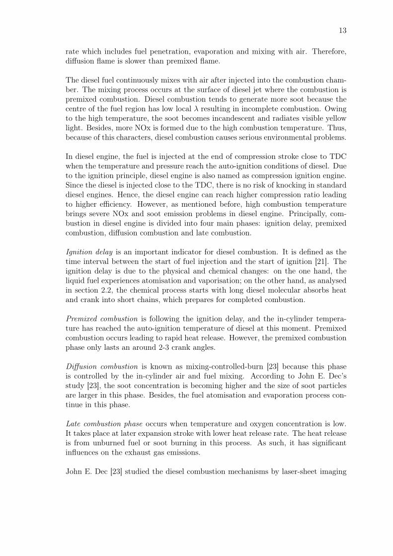
and summarised a conceptual model of diesel combustion. Fig.7 illustrates dieselcombustion process in detail. The initial jet fuel development occurs at 0-4.5 afterthe start of injection (ASI) when liquid fuel penetrates in the cylinder and evapo-rates to gas phase. Auto-ignition occurs between 3-5 ASI depending on differentoperating conditions. John E. Dec summarises that diesel molecular breaks down toshort chain and polycyclic aromatic hydrocarbons (PAH) at 4.5-5 ASI. It is followedby small soot particles generation between 5-6 ASI. Diffusion flame first takes placeat around 6.5 ASI and it can be observed from the figure the diffusion flame coversthe whole portion of fuel at downstream. The jet fuel piece continuously penetratesin the cylinder and higher concentration soot formed at around 9 ASI. Mixing con-trolled combustion condition is reached between 9 ASI to the end of injection.
Figure 7: Scheme of Diesel Combustion Model [23]
2.3.3 Dual Fuel Combustion
Dual fuel combustion engine uses two types of fuels in which both premixed com-bustion, and non-premixed combustion exist. The low reactivity fuel (CH4, NG,ethanol, methanol, etc.) is injected in the early stage to mix with air and it isignited by the high reactivity fuel (usually diesel) which is injected close to TDC.
15
The small amount of diesel fuel, also known as pilot fuel, burns after injection andcauses the in-cylinder temperature reaches the auto-ignition temperature of the pre-mixed fuel. Then the premixed combustion occurs. The dual fuel concept is similarto RCCI combustion, but the principle is different due to the high reactivity fuelinjection timing. The high reactivity fuel in dual fuel is injected close to TDC whichmeans the dual fuel combustion depends on both high reactivity fuel spray physicsand chemical kinetics of premixed fuel. By contrast, RCCI combustion is only reliedon chemical kinetics because of earlier high reactivity fuel injection.
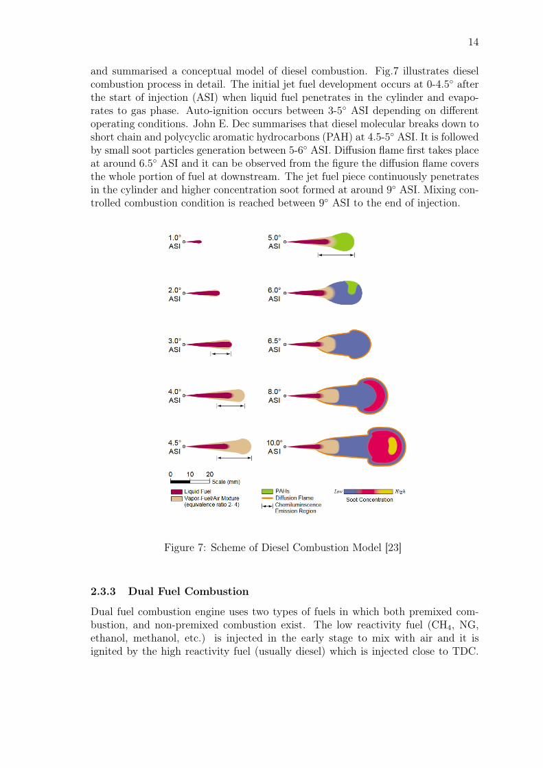
The heat release of dual fuel combustion can be divided into three overlapping phases[24]. Diffusion flame of pilot diesel is formed in the first stage that contains dieselfuel injection, evaporation and auto-ignition. When the surrounding temperaturereaches the auto-ignition point of the premixed fuel, the second phase starts. Thelow reactivity fuel combustion is surrounding the diesel pilot premixed region. Thelast stage is the premixed turbulent flame propagation. Fig.8 illustrates three phasesin both heavy load and light load conditions. Additionally, G. A. Karim [24] studiedthe influence of λ in dual fuel combustion. When dual fuel is operated at very leanconditions, the premixed fuel enters a rich and high temperature area. As a result,most premixed fuel is burned in the first and second phase, so there is no significantflame propagation in the last phase.
Figure 8: Dual Fuel Combustion Phase [24]
R. Pettinen studied the methane/diesel dual fuel combustion characters in high loadlean conditions. The results suggest the rapid premixed flame propagation occurswhen methane λ is lower than 2.2. Besides, it also concludes that to reach highefficiency, the methane substitution rate should be higher than 90% and overall λ begreater than 2 [22]. Z. Ahmad studied methane/diesel dual fuel via an optical engine,and the results indicate premixed flame fronts derive from combustion chamberwall propagating to the centre. Also, the ignition delay in 82% to 88% methanesubstitution is 1.5 to 2 times longer than diesel fuel combustion [25].
16
2.3.4 Homogeneous Charge Compression Ignition Combustion (HCCI)
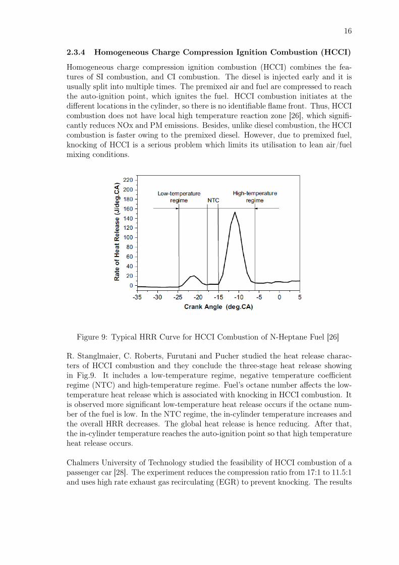
Homogeneous charge compression ignition combustion (HCCI) combines the fea-tures of SI combustion, and CI combustion. The diesel is injected early and it isusually split into multiple times. The premixed air and fuel are compressed to reachthe auto-ignition point, which ignites the fuel. HCCI combustion initiates at thedifferent locations in the cylinder, so there is no identifiable flame front. Thus, HCCIcombustion does not have local high temperature reaction zone [26], which signifi-cantly reduces NOx and PM emissions. Besides, unlike diesel combustion, the HCCIcombustion is faster owing to the premixed diesel. However, due to premixed fuel,knocking of HCCI is a serious problem which limits its utilisation to lean air/fuelmixing conditions.
Figure 9: Typical HRR Curve for HCCI Combustion of N-Heptane Fuel [26]
R. Stanglmaier, C. Roberts, Furutani and Pucher studied the heat release charac-ters of HCCI combustion and they conclude the three-stage heat release showingin Fig.9. It includes a low-temperature regime, negative temperature coefficientregime (NTC) and high-temperature regime. Fuel’s octane number affects the low-temperature heat release which is associated with knocking in HCCI combustion. Itis observed more significant low-temperature heat release occurs if the octane num-ber of the fuel is low. In the NTC regime, the in-cylinder temperature increases andthe overall HRR decreases. The global heat release is hence reducing. After that,the in-cylinder temperature reaches the auto-ignition point so that high temperatureheat release occurs.
Chalmers University of Technology studied the feasibility of HCCI combustion of apassenger car [28]. The experiment reduces the compression ratio from 17:1 to 11.5:1and uses high rate exhaust gas recirculating (EGR) to prevent knocking. The results
17
show the combustion phase is adequately controlled in lower compression ratio andhigh EGR rate, while the coefficient of variation (COV) is around 7% suggestingunstable combustion due to early ignition. Besides, the results suggest NOx and sootemissions are reduced by more than 95%, but the HC and CO emissions increasedsignificantly. It indicates the incomplete fuel combustion in HCCI mode resultingin fuel consumption rising around 10-20%.
2.4 Reactivity Controlled Compression Ignition (RCCI)
Reactivity controlled compression ignition combustion is developed by the Universityof Wisconsin-Madison Engine Research Centre. It is a variation of HCCI combustionmode that a low reactivity fuel is applied with the high reactivity fuel to control thecombustion. In general, high reactivity refers to the fuel with high cetane numberssuch as diesel. On the contrary, gasoline, CH4 and alcohol which have low cetanenumber are used as low reactivity fuels. Thus, the RCCI also belongs to dual fueltechnology, but its combustion mechanism is similar to HCCI mode instead of con-ventional dual fuel mode. The motivation for developing RCCI technology is that ithas high efficiency, low NOx and PM emissions due to the low combustion temper-ature. Besides, the low reactivity fuel makes it more feasible to control comparedto HCCI mode. In the laboratory scale, the iso-octane/n-heptane, gasoline/diesel,Alkane/diesel and alcohol/diesel are widely studied. This master thesis will continuethe previous study and focus on methanol/diesel to discover the RCCI combustionbehaviours.
There are mainly two methanol injection strategies: port injection to the intakemanifold and direct injection to the combustion chamber. Z.Q. Jia [29] studied themethanol injection strategy, and she concludes port injection and direct injectionhave similar patterns, but the thermal efficiency is slightly higher in the port in-jection case. Distinguished from dual fuel mode in which diesel injection timing isclose to TDC, the diesel injection of RCCI mode is usually earlier than 15 CADBTDC. Early diesel injection is to form a homogeneous mixture of methanol, dieseland air. As a result, the reactivity stratification is created leading to promisingcombustion mode. More specific, methanol has high octane number preventing theearly combustion which occurs in high load HCCI mode. Besides, the low cetanenumber of methanol can be balanced by diesel fuel. The adverse cooling effect ofmethanol is diminished by increasing air intake temperature.
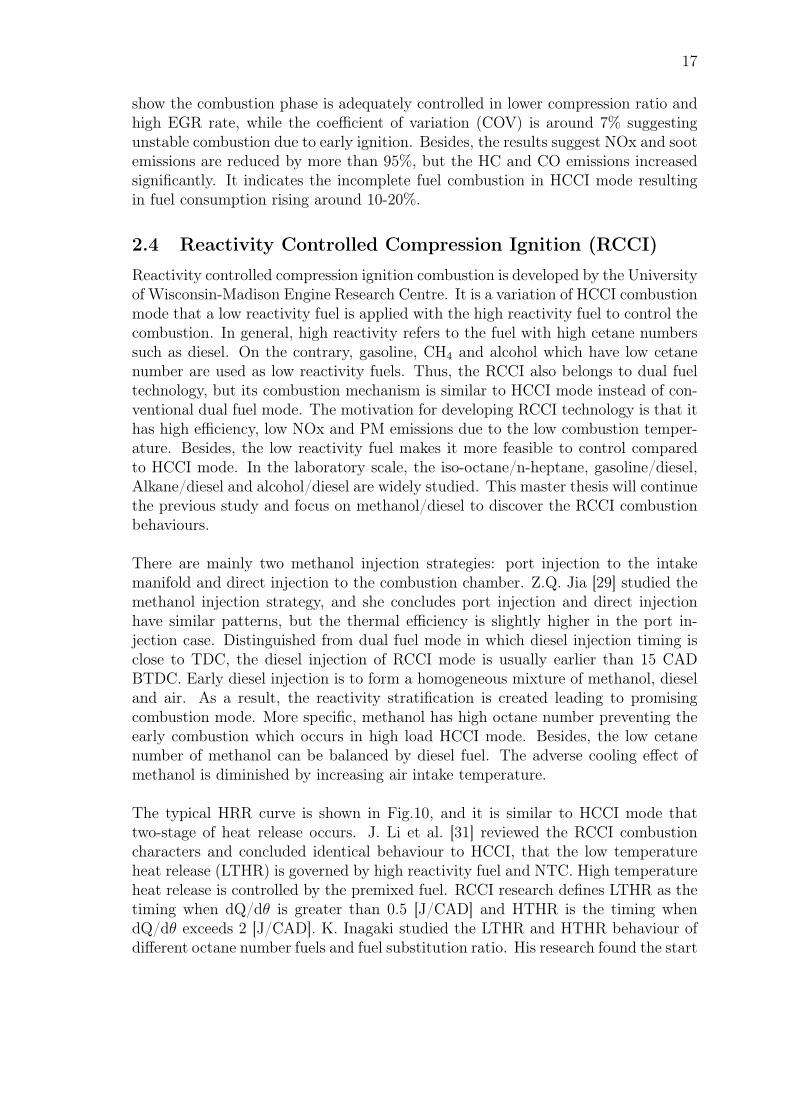
The typical HRR curve is shown in Fig.10, and it is similar to HCCI mode thattwo-stage of heat release occurs. J. Li et al. [31] reviewed the RCCI combustioncharacters and concluded identical behaviour to HCCI, that the low temperatureheat release (LTHR) is governed by high reactivity fuel and NTC. High temperatureheat release is controlled by the premixed fuel. RCCI research defines LTHR as thetiming when dQ/dθ is greater than 0.5 [J/CAD] and HTHR is the timing whendQ/dθ exceeds 2 [J/CAD]. K. Inagaki studied the LTHR and HTHR behaviour ofdifferent octane number fuels and fuel substitution ratio. His research found the start
18
of LTHR is advanced with RON decreasing and a stronger LTHR peak occurs inlower RON case. Besides, the results also indicate the LTHR is reduced if more lowRON fuel is used in the experiment. K. Inagaki’s research illustrates the RCCI fuelheat release is significantly affected by the in-cylinder fuel reactivity stratification,namely, the properties of chosen fuels and mixing strategy [30].
Figure 10: Typical HRR Curve for RCCI Combustion [30]
Besides of reactivity stratification, due to uneven mixing in the combustion cham-ber, the local λ is also different in the cylinder. The combustion at the local richregion will produce soot and NOx. Additionally, owing to fuel distribution in thecombustion chamber, the fuel evaporation process will also lead to temperaturestratification in the cylinder. Other parameters such as diesel injection strategy,EGR ratio, compression ratio and bowl geometry also influence RCCI combustion.The following section will analyse each parameter.
2.4.1 Influence of Parameters on RCCI
Fuel ratio: Methanol substitution rate (MSR) is typically used to measure the fuelratio. It calculates from the energy content of two fuels (Eq.3), where E refers tothe energy flow. According to the previous study, the low reactivity fuel ratio caneven reach 90%. The fuel reactivity is eventually quantified by fuel cetane numberwhich is decided by the methanol substitution rate. Eq.4 indicates the calculationof RCCI fuel cetane number, where X is the mole fraction of each fuel.
MSR =Emethanol
Emethanol + Ediesel
(3)
CNRCCI =CNdiesel ×Xdiesel + CNmethanol ×Xmethanol
Xdiesel +Xmethanol
[28] (4)
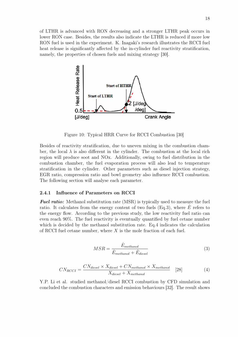
Y.P. Li et al. studied methanol/diesel RCCI combustion by CFD simulation andconcluded the combustion characters and emission behaviours [32]. The result shows
19
the ignition delay increases and the peak of HRR decreases with MSR increasing.The simulation results also suggest the CN distribution is not homogeneous in thecombustion chamber and combustion phase stratification is observed (Fig.11). HighCN region usually contains more diesel fuel and it is ignited first. Then the methanolwith low CN is ignited by diesel. Y.P. Li concluded that with higher MSR, this com-bustion stratification is more significant. As a result, the heat release from the initialcombustion phase is decreased due to the lower reaction rate, which further leads toHRR peak decreasing.
Figure 11: Cetane Number Distribution in Different MSR at 4 BTDC. PortMethanol Injection; Diesel Injection Timing: 27 BTDC [32]
Figure 12: Apparent Heat Release Rates of RCCI [33]
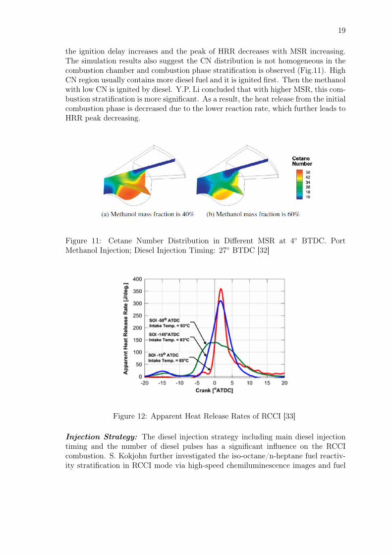
Injection Strategy: The diesel injection strategy including main diesel injectiontiming and the number of diesel pulses has a significant influence on the RCCIcombustion. S. Kokjohn further investigated the iso-octane/n-heptane fuel reactiv-ity stratification in RCCI mode via high-speed chemiluminescence images and fuel
20
tracer fluorescence [33]. The research exams the fuel mixture at three different n-heptane injection timings: 145, 50 and 15 BTDC. The results indicate the 145BTDC and 15 BTDC cases have similar HRR curve, while the less heat is releasedin 50 BTDC case. As shown in Fig.12, the heat release duration of 50 BTDC islonger than 15 and 145 BTDC cases, but the peak of HRR is much lower. A tailcan be observed from 15 BTDC case, and S. Kokjohn explains it as the slow com-bustion inside rich region of the n-heptane jet and some lean regions of iso-octane.
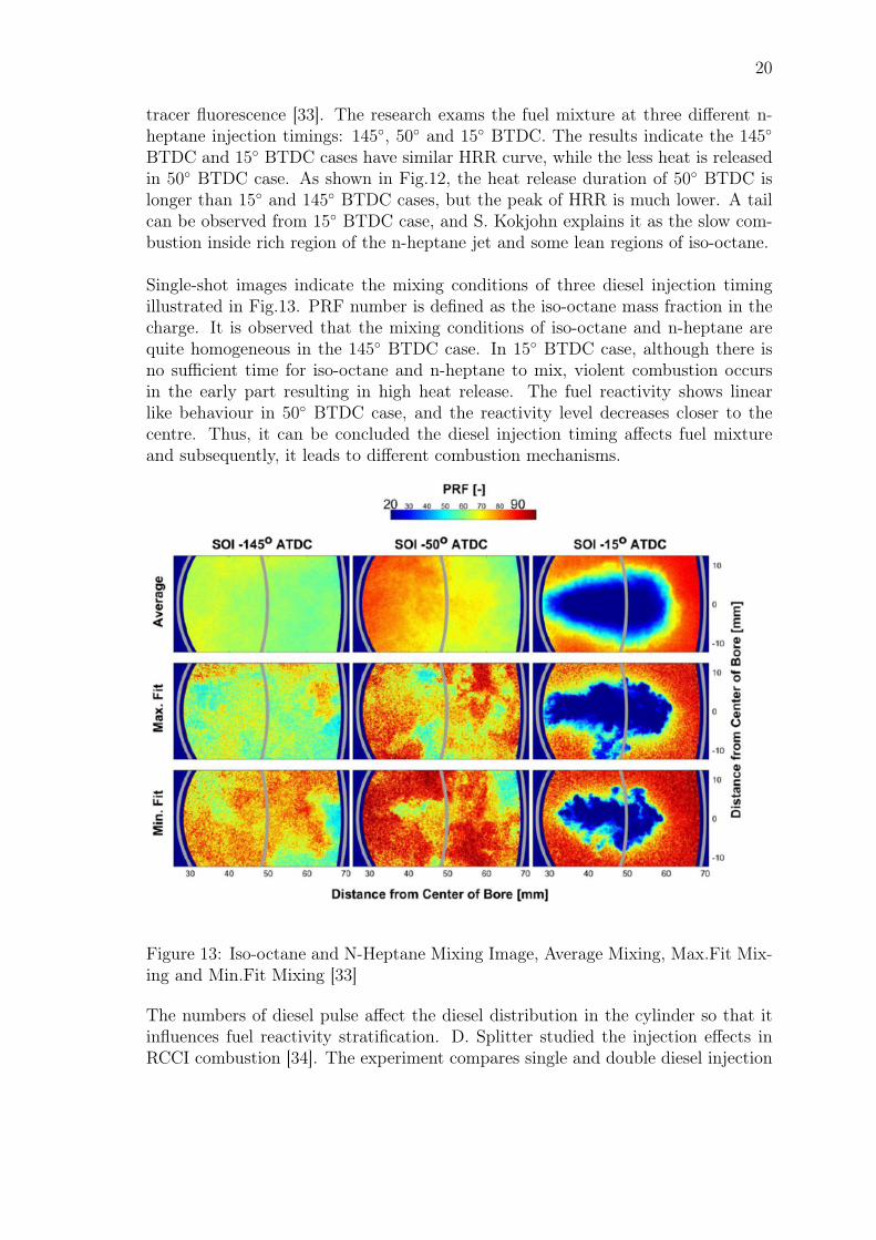
Single-shot images indicate the mixing conditions of three diesel injection timingillustrated in Fig.13. PRF number is defined as the iso-octane mass fraction in thecharge. It is observed that the mixing conditions of iso-octane and n-heptane arequite homogeneous in the 145 BTDC case. In 15 BTDC case, although there isno sufficient time for iso-octane and n-heptane to mix, violent combustion occursin the early part resulting in high heat release. The fuel reactivity shows linearlike behaviour in 50 BTDC case, and the reactivity level decreases closer to thecentre. Thus, it can be concluded the diesel injection timing affects fuel mixtureand subsequently, it leads to different combustion mechanisms.
Figure 13: Iso-octane and N-Heptane Mixing Image, Average Mixing, Max.Fit Mix-ing and Min.Fit Mixing [33]
The numbers of diesel pulse affect the diesel distribution in the cylinder so that itinfluences fuel reactivity stratification. D. Splitter studied the injection effects inRCCI combustion [34]. The experiment compares single and double diesel injection

21
in four regions: diesel injection before 110 BTDC, 70-110 BTDC, 40-70 BTDCand after 40 BTDC, respectively. The results indicate that split diesel injectionsreduce CO and HC emissions by 40% and it leads to 1% thermal efficiency increasing.Single diesel injection usually results in higher peak HRR except for 50 BTDCexperiment. Additionally, diesel-like combustion was found in late injection timingswith high NOx emissions, which is mainly due to local λ and reactivity stratification.However, linear impingement occurs when the diesel injection is earlier than 70BTDC. Y.P. Li summarise the characters of SOI and MSR showing in Fig.14. Itcan be concluded that at certain λ, diesel SOI and methanol fraction have influencedthe combustion mode directly.
Figure 14: The Influence of Methanol Substitution Ratio and Diesel Start of Injec-tion Timing on The Combustion Mode [35]
Compression ratio and Bowl geometry: From engine structure point of view,the compression ratio and bowl geometry have effects on RCCI combustion. NG/dieselRCCI experiments were conducted by Denbratt during which 14 and 17 compressionratio were used [31]. It is observed 14 compression ratio has longer ignition delay,combustion duration and lower peak HRR. While when the compression ratio is 17,knocking tends to occur at high load. Therefore, Denbratt concluded 14 compres-sion ratio is more appropriate at high load operating conditions.
Bowl geometry has influences on air/fuel mixing and heat transfer, so it affects thethermal efficiency of RCCI combustion. D. Splitter improved the shape of the pis-ton, and it can reduce the heat losses. It is also discovered by modifying the pistonshape, RCCI brake thermal efficiency can be increased by 3% [31].
EGR rate: EGR has significant influences on the combustion temperature whichadditionally affects emissions. Principally, the feature of EGR is similar to low re-activity fuel, so in RCCI mode, EGR usage is expected to reduce. However, many
22
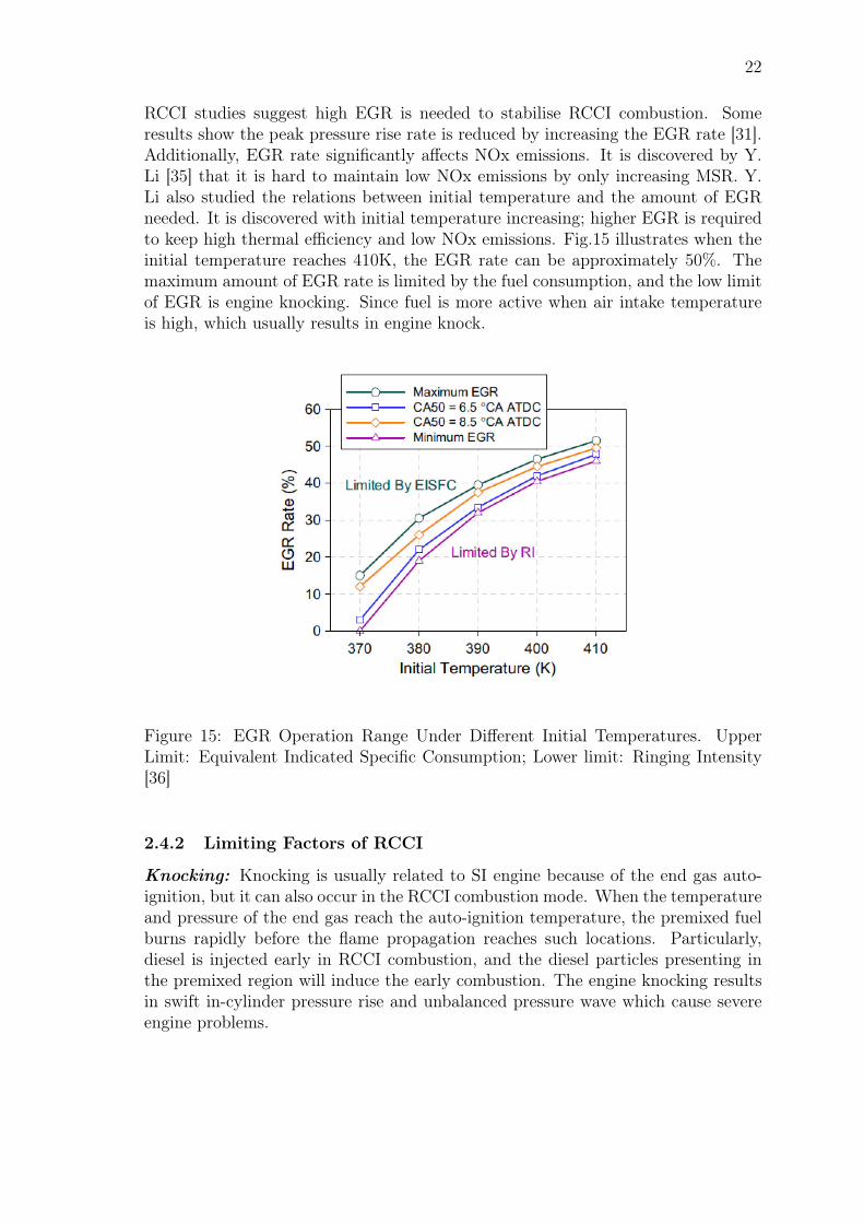
RCCI studies suggest high EGR is needed to stabilise RCCI combustion. Someresults show the peak pressure rise rate is reduced by increasing the EGR rate [31].Additionally, EGR rate significantly affects NOx emissions. It is discovered by Y.Li [35] that it is hard to maintain low NOx emissions by only increasing MSR. Y.Li also studied the relations between initial temperature and the amount of EGRneeded. It is discovered with initial temperature increasing; higher EGR is requiredto keep high thermal efficiency and low NOx emissions. Fig.15 illustrates when theinitial temperature reaches 410K, the EGR rate can be approximately 50%. Themaximum amount of EGR rate is limited by the fuel consumption, and the low limitof EGR is engine knocking. Since fuel is more active when air intake temperatureis high, which usually results in engine knock.
Figure 15: EGR Operation Range Under Different Initial Temperatures. UpperLimit: Equivalent Indicated Specific Consumption; Lower limit: Ringing Intensity[36]
2.4.2 Limiting Factors of RCCI
Knocking: Knocking is usually related to SI engine because of the end gas auto-ignition, but it can also occur in the RCCI combustion mode. When the temperatureand pressure of the end gas reach the auto-ignition temperature, the premixed fuelburns rapidly before the flame propagation reaches such locations. Particularly,diesel is injected early in RCCI combustion, and the diesel particles presenting inthe premixed region will induce the early combustion. The engine knocking resultsin swift in-cylinder pressure rise and unbalanced pressure wave which cause severeengine problems.
23
The knocking phenomenon is quantified by J.A. Eng [38] who summarised the ring-ing intensity (RI) of fuel is correlated with max. in-cylinder pressure, temperatureand max. pressure rise rate (Eq.5).
RI =1
2γ· (0.05(dP/dt)max)2
Pmax
·√γRTmax (5)
According to the numerical study done by D.Z. Zhou on methanol/biodiesel RCCIcombustion, EGR is a practical approach to prevent engine knocking even at fullload. Besides, the SOI of biodiesel is tested, and results show retarded SOI can alsoattenuate knocking. It is because there will be less premixed diesel in the cylinder ifdiesel SOI is delayed. Additionally, it is found more premixed methanol in the endgas tends to cause engine knocking [39]. Y. Li also studied the ringing intensity ofmethanol/diesel RCCI, and he concluded methanol/diesel combination has higherringing intensity compared with gasoline/diesel at the same λ and air intake temper-ature. Due to the simple molecule structure, methanol prolongs the ignition delay.It means methanol and diesel have a longer time to mix homogeneously [40]. Evenlydistributed methanol can effectively prevent early combustion of diesel. Althoughthe use of methanol diminishes knocking to some degree, it still brings the upperlimitations of operation load and maximum pressure rise rate.
Misfire: When methanol is not burning properly and most methanol slips, thephenomenon is referred to partial burning or even misfire. Several reasons are cor-responding to incomplete burning or misfire in methanol/diesel RCCI combustion.Fuel mixing conditions are critical to RCCI combustion. If high reactivity fuel andlow reactivity do not distribute evenly in the combustion chamber, the methanol maybe exhausted before flame reaches the end gas. Methanol λ is another factor affect-ing methanol partial burning. Because of the flammability limitation, methanol doesnot burn in very lean conditions. However, many studies show that if methanol anddiesel can mix homogeneously, methanol λ does not play an important role. Besides,air intake temperature is vital to methanol combustion, since it actives the fuel sig-nificantly. MSR is also considered as a reason for partial burning. When MSR istoo high, the flame speed becomes slow due to sparse diesel particle distributions sothat methanol partial burning occurs. Fig.14 indicates methanol misfire happens ifMSR is greater than 75%.
2.4.3 Emission Characters of RCCI
The essential motivation of studying RCCI combustion is that theoretically, RCCIcombustion can achieve low NOx and PM emissions due to low temperature com-bustion. While the high unburned hydrocarbon and CO emissions bring challengesto RCCI combustion. This section is going to analyse the formation of NOx, soot,unburned hydrocarbon and CO in standard diesel engines and how RCCI affectsthose emissions.
24
NOx: Nitrogen oxides (NOx) mainly refer to NO2 and NO which is generated fromboth air and fuel in the combustion process. N constituent is negligible in diesel andmethanol fuel and therefore, the NOx in the internal combustion engine is mostlyderived from air. There are three paths to generate NOx: thermal NOx, promptNOx and N2O to NOx path. Thermal NOx is the most common path for NOxgeneration and the Zelodovich mechanism explains the formation of thermal NO:
O + N2 NO + N (k)O2 + N NO + O (l)N + OH NO + H (m)
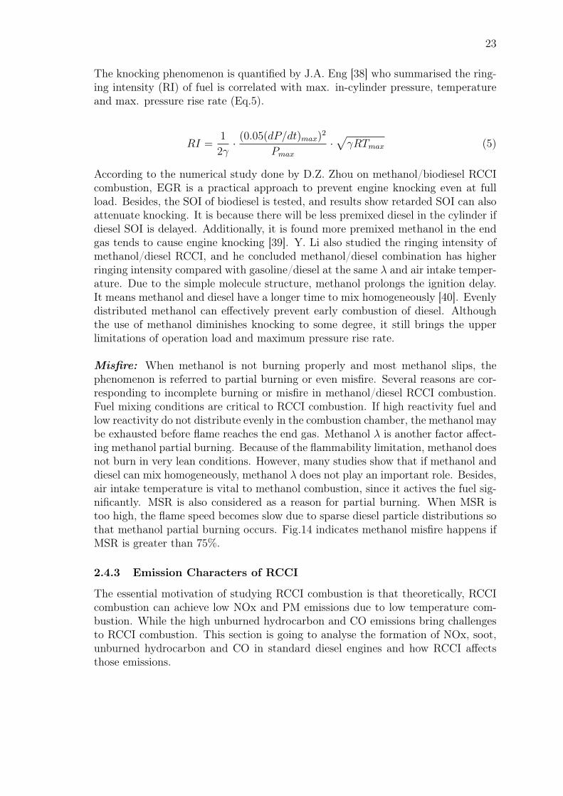
Fig.16 shows the temperature and φ conditions of NOx formation in the internalcombustion engines. The high temperature is required for NOx generation. It isclearly illustrated in Fig.16 that NOx formation occurs when the local temperatureis greater than 2200K. In terms of φ, the NOx is generated when the combustion is instoichiometric or lean conditions. Diesel engine works under extra air conditions andthe local jet combustion region is higher than 2200K. Therefore, the NOx emissionis a severe issue of the diesel engine.
Figure 16: The Conditions of NOx and Soot Generation, φ-T Map [41]
Due to early diesel injection, the RCCI combustion avoids diesel rich high tempera-ture. Although the combustion is taking place in relatively lean conditions, the lowtemperature effectively reduces the NOx formations.
25
PM: Particulate matter (PM) mainly contains soot which is generated in rich con-ditions. Fig.16 also shows the formation of soot that is generated between 1600Kto 2200K temperature and fuel-rich conditions. In diesel combustion, polyaromatichydrocarbons (PAH) is first produced in rich conditions, and PAH grows via con-glomeration, subsequently, soot is formed. This process is shown in Fig.7. Asanalysed before, RCCI combustion circumvents the rich diesel jet. Hence, the sootemission can also be reduced.
Unburned HC: Unburned hydrocarbon (HC) is an issue concerning in premixedcombustion, while there is much lower HC emission of diesel engine. The flamequenching is one of the main reason for HC emissions. In the RCCI combustion,methanol is premixed with air and in lean conditions. Thus, the lean condition andsparse methanol distribution can cause flame quenching. The flame cannot reacha part of end methanol. As a result, it increases not only CO emissions, but alsoincreases the unburned methanol emissions.
CO: As shown in Fig.4, CO is an intermediate product and will eventually convertto CO2. When the combustion temperature is too low, or the air is not efficient, theCO will fail to further convert CO2. In this RCCI experiment, the methanol is inlean conditions (normally overall φ 0.44, methanol φ 0.25), so sufficient air presentin the combustion chamber. However, the global temperature is low in RCCI com-bustion, which prevents the oxidation of CO. Hence, although RCCI combustionhas positive effects on NOx and soot emissions, the CO and unburned hydrocarbonbrings challenges to the technology.
26
3 Research MethodologyThe majority part of the thesis is the LEO1 experiment and it is supported bymethanol evaporation GT-SUITE simulation. The objective of GT-SUITE simu-lation is to understand the cooling effects of methanol vaporisation. Since bothsimulation and experiment are based on the all-metal engine, LEO1, the chapterwill firstly introduce LEO1 configuration. Then, LEO1 based GT-SUITE model,LEO1 experimental methods and data post processing are instituted respectively inthe following sections.
3.1 LEO1 Engine Setup
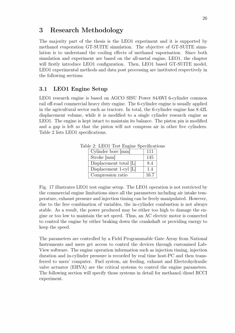
LEO1 research engine is based on AGCO SISU Power 84AWI 6-cylinder commonrail off-road commercial heavy duty engine. The 6-cylinder engine is usually appliedin the agricultural sector such as tractors. In total, the 6-cylinder engine has 8.42Ldisplacement volume, while it is modified to a single cylinder research engine asLEO1. The engine is kept intact to maintain its balance. The piston pin is modifiedand a gap is left so that the piston will not compress air in other five cylinders.Table 2 lists LEO1 specifications.
Table 2: LEO1 Test Engine SpecificationsCylinder bore [mm] 111Stroke [mm] 145Displacement total [L] 8.4Displacement 1-cyl [L] 1.4Compression ratio 16.7
Fig. 17 illustrates LEO1 test engine setup. The LEO1 operation is not restricted bythe commercial engine limitations since all the parameters including air intake tem-perature, exhaust pressure and injection timing can be freely manipulated. However,due to the free combination of variables, the in-cylinder combustion is not alwaysstable. As a result, the power produced may be either too high to damage the en-gine or too low to maintain the set speed. Thus, an AC electric motor is connectedto control the engine by either braking down the crankshaft or providing energy tokeep the speed.
The parameters are controlled by a Field Programmable Gate Array from NationalInstruments and users get access to control the devices through customised Lab-View software. The engine operation information such as injection timing, injectionduration and in-cylinder pressure is recorded by real time host-PC and then trans-ferred to users’ computer. Fuel system, air feeding, exhaust and Electrohydraulicvalve actuator (EHVA) are the critical systems to control the engine parameters.The following section will specify those systems in detail for methanol/diesel RCCIexperiment.
27
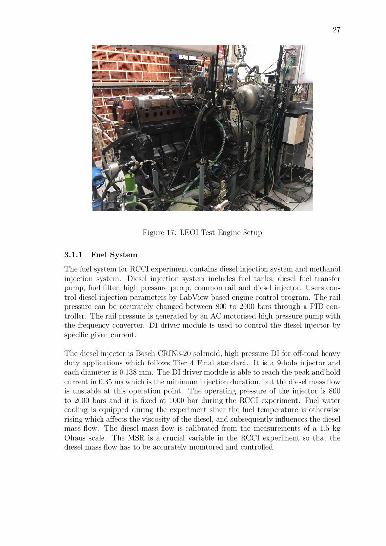
Figure 17: LEOI Test Engine Setup
3.1.1 Fuel System
The fuel system for RCCI experiment contains diesel injection system and methanolinjection system. Diesel injection system includes fuel tanks, diesel fuel transferpump, fuel filter, high pressure pump, common rail and diesel injector. Users con-trol diesel injection parameters by LabView based engine control program. The railpressure can be accurately changed between 800 to 2000 bars through a PID con-troller. The rail pressure is generated by an AC motorised high pressure pump withthe frequency converter. DI driver module is used to control the diesel injector byspecific given current.
The diesel injector is Bosch CRIN3-20 solenoid, high pressure DI for off-road heavyduty applications which follows Tier 4 Final standard. It is a 9-hole injector andeach diameter is 0.138 mm. The DI driver module is able to reach the peak and holdcurrent in 0.35 ms which is the minimum injection duration, but the diesel mass flowis unstable at this operation point. The operating pressure of the injector is 800to 2000 bars and it is fixed at 1000 bar during the RCCI experiment. Fuel watercooling is equipped during the experiment since the fuel temperature is otherwiserising which affects the viscosity of the diesel, and subsequently influences the dieselmass flow. The diesel mass flow is calibrated from the measurements of a 1.5 kgOhaus scale. The MSR is a crucial variable in the RCCI experiment so that thediesel mass flow has to be accurately monitored and controlled.
28
Methanol fuel system contains a fuel vessel, methanol transfer pump, fuel filter,methanol rail and methanol injector. The pressure sensor is installed at the methanolrail. The methanol rail has 3-5 bar pressure which is generated by methanol transferpump and controlled by the regulator. The regulator keeps the pressure gap betweenmethanol rail and manifold the same. The fuel is injected into the intake manifoldmixing with air during the intake stroke.
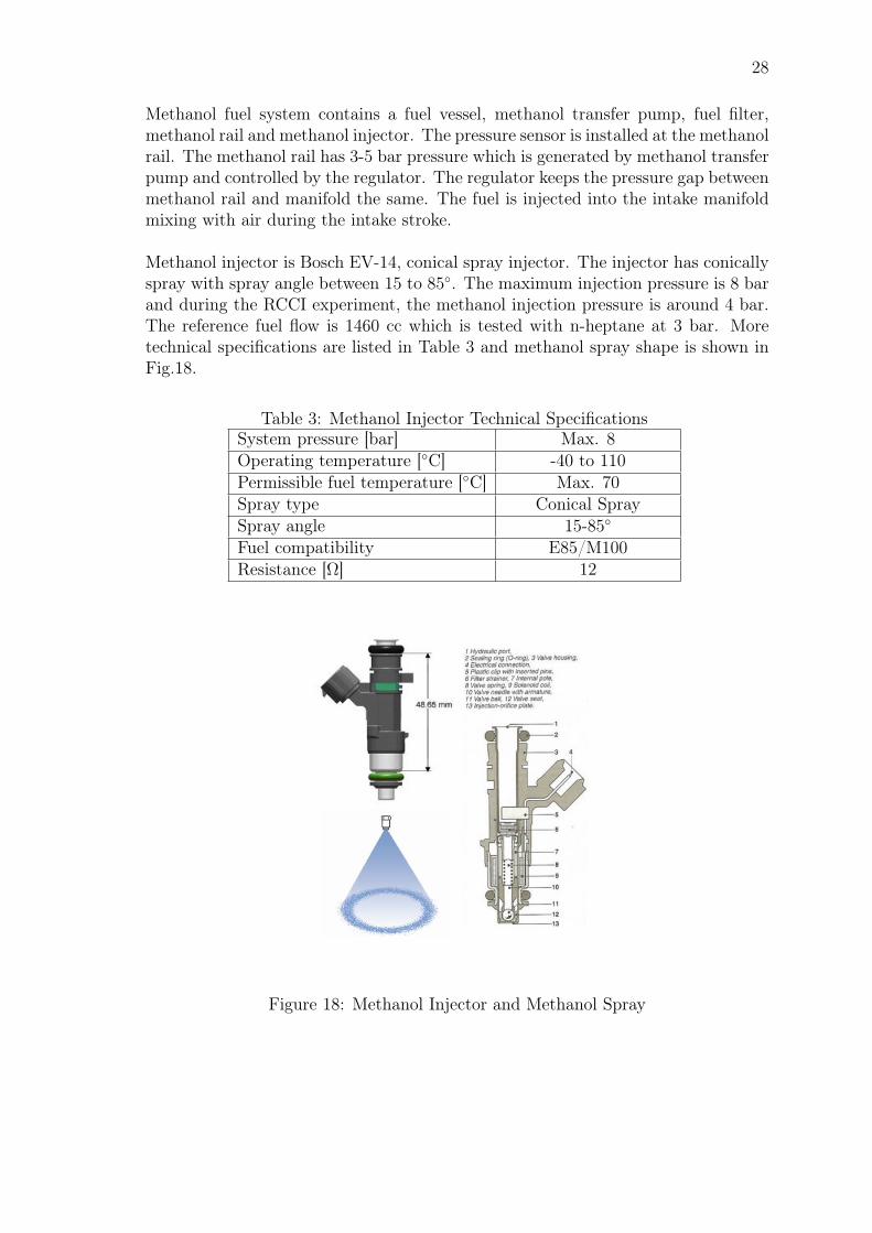
Methanol injector is Bosch EV-14, conical spray injector. The injector has conicallyspray with spray angle between 15 to 85. The maximum injection pressure is 8 barand during the RCCI experiment, the methanol injection pressure is around 4 bar.The reference fuel flow is 1460 cc which is tested with n-heptane at 3 bar. Moretechnical specifications are listed in Table 3 and methanol spray shape is shown inFig.18.
Table 3: Methanol Injector Technical SpecificationsSystem pressure [bar] Max. 8Operating temperature [C] -40 to 110Permissible fuel temperature [C] Max. 70Spray type Conical SpraySpray angle 15-85
Fuel compatibility E85/M100Resistance [Ω] 12
Figure 18: Methanol Injector and Methanol Spray
29
3.1.2 Air Feeding, Exhaust and EHVA system
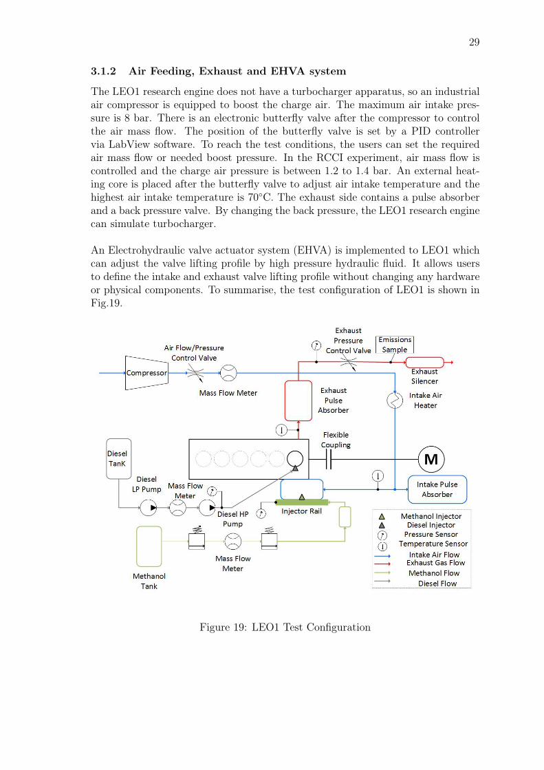
The LEO1 research engine does not have a turbocharger apparatus, so an industrialair compressor is equipped to boost the charge air. The maximum air intake pres-sure is 8 bar. There is an electronic butterfly valve after the compressor to controlthe air mass flow. The position of the butterfly valve is set by a PID controllervia LabView software. To reach the test conditions, the users can set the requiredair mass flow or needed boost pressure. In the RCCI experiment, air mass flow iscontrolled and the charge air pressure is between 1.2 to 1.4 bar. An external heat-ing core is placed after the butterfly valve to adjust air intake temperature and thehighest air intake temperature is 70C. The exhaust side contains a pulse absorberand a back pressure valve. By changing the back pressure, the LEO1 research enginecan simulate turbocharger.
An Electrohydraulic valve actuator system (EHVA) is implemented to LEO1 whichcan adjust the valve lifting profile by high pressure hydraulic fluid. It allows usersto define the intake and exhaust valve lifting profile without changing any hardwareor physical components. To summarise, the test configuration of LEO1 is shown inFig.19.
Figure 19: LEO1 Test Configuration
30
3.2 GT-SUITE Simulation of Methanol Evaporation
Due to the high latent heat of vaporisation (1150 MJ/kg), methanol evaporationbrings significant cooling effects to the cylinder. Although the cooling impact in-creases the ringing intensity of the charge, it negatively affects fuel ignition andincreases the HC emissions. Therefore, it is necessary to investigate the methanolevaporation quantitatively. GT-SUITE is used to model LEO1 engine, particularly,methanol injection process. The in-cylinder temperature at top dead centre (TDC)and the temperature at intake valve close (IVC) are calculated.
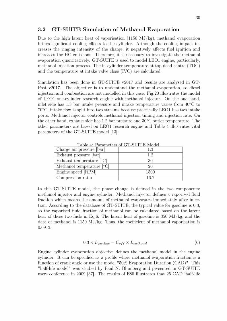
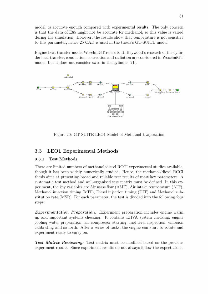
Simulation has been done in GT-SUITE v2017 and results are analysed in GT-Post v2017. The objective is to understand the methanol evaporation, so dieselinjection and combustion are not modelled in this case. Fig.20 illustrates the modelof LEO1 one-cylinder research engine with methanol injector. On the one hand,inlet side has 1.3 bar intake pressure and intake temperature varies from 40C to70C; intake flow is split into two streams because practically LEO1 has two intakeports. Methanol injector controls methanol injection timing and injection rate. Onthe other hand, exhaust side has 1.2 bar pressure and 30C outlet temperature. Theother parameters are based on LEO1 research engine and Table 4 illustrates vitalparameters of the GT-SUITE model [13].
Table 4: Parameters of GT-SUITE ModelCharge air pressure [bar] 1.3Exhaust pressure [bar] 1.2Exhaust temperature [C] 30Methanol temperature [C] 20Engine speed [RPM] 1500Compression ratio 16.7
In this GT-SUITE model, the phase change is defined in the two components:methanol injector and engine cylinder. Methanol injector defines a vaporised fluidfraction which means the amount of methanol evaporates immediately after injec-tion. According to the database of GT-SUITE, the typical value for gasoline is 0.3,so the vaporised fluid fraction of methanol can be calculated based on the latentheat of these two fuels in Eq.6. The latent heat of gasoline is 350 MJ/kg, and thedata of methanol is 1150 MJ/kg. Thus, the coefficient of methanol vaporisation is0.0913.
0.3× Lgasoline = Cvff × Lmethanol (6)
Engine cylinder evaporation objective defines the methanol model in the enginecylinder. It can be specified as a profile where methanol evaporation fraction is afunction of crank angle or use the model "50% Evaporation Duration (CAD)". This"half-life model" was studied by Paul N. Blumberg and presented in GT-SUITEusers conference in 2009 [37]. The results of E85 illustrates that 25 CAD ‘half-life
31
model’ is accurate enough compared with experimental results. The only concernis that the data of E85 might not be accurate for methanol, so this value is variedduring the simulation. However, the results show that temperature is not sensitiveto this parameter, hence 25 CAD is used in the thesis’s GT-SUITE model.
Engine heat transfer model WoschniGT refers to B. Heywood’s research of the cylin-der heat transfer, conduction, convection and radiation are considered in WoschniGTmodel, but it does not consider swirl in the cylinder [21].
Figure 20: GT-SUITE LEO1 Model of Methanol Evaporation
3.3 LEO1 Experimental Methods
3.3.1 Test Methods
There are limited numbers of methanol/diesel RCCI experimental studies available,though it has been widely numerically studied. Hence, the methanol/diesel RCCIthesis aims at presenting broad and reliable test results of most key parameters. Asystematic test method and well-organised test matrix must be defined. In this ex-periment, the key variables are Air mass flow (AMF), Air intake temperature (AIT),Methanol injection timing (MIT), Diesel injection timing (DIT) and Methanol sub-stitution rate (MSR). For each parameter, the test is divided into the following foursteps:
Experimentation Preparation: Experiment preparation includes engine warmup and important systems checking. It contains EHVA system checking, enginecooling water preparation, air compressor starting, fuel level inspection, emissioncalibrating and so forth. After a series of tasks, the engine can start to rotate andexperiment ready to carry on.
Test Matrix Reviewing: Text matrix must be modified based on the previousexperiment results. Since experiment results do not always follow the expectations,
32
test points must be adjusted. For example, to study the influence of air intake tem-perature, all other parameters should be the same in different temperature pointswhich are set as 20C, 30C and 40C initially. However, the start of ignition istoo early in 40C air intake case and the SOI has to be adjusted. As such, thetemperature step should be changed smaller to 20C and 25C.
Combustion Stabilisation and Data Recording: Only the test point with sta-ble combustion are regarded as valid points. Specifically, stabilised combustion refersto pressure rising occurs around TDC without sharp pressure increasing and pres-sure fluctuation, as well as constant NOx level. After the combustion is stabilised,cylinder pressure of at least forty cycles is recorded. The engine operating condi-tions such as air mass flow, air intake temperature, methanol and diesel injectioninformation are saved as well.
Data Analysing: The recorded data is analysed by Matlab 2017a and the calcu-lation methods refer to "International Combustion Engine Fundamentals" by Hey-wood. The calculation details are introduced in Section 3.4.
3.3.2 Parameters Setup and Test Matrix
As discussed in section 2.3, diesel injection strategy is fundamentally crucial to RCCIcombustion. The experiment is hence divided into two groups: single diesel injec-tion experiments and split diesel injection experiments. In the split diesel injectionexperiments, early diesel injection event is named as premixed diesel and the seconddiesel pulse is designated as pilot diesel in the experiment.
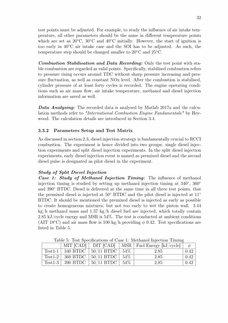
Study of Split Diesel InjectionCase 1: Study of Methanol Injection Timing: The influence of methanolinjection timing is studied by setting up methanol injection timing at 340, 360and 390 BTDC. Diesel is delivered at the same time in all three test points, thatthe premixed diesel is injected at 50 BTDC and the pilot diesel is injected at 11BTDC. It should be mentioned the premixed diesel is injected as early as possibleto create homogeneous mixtures, but not too early to wet the piston wall. 3.44kg/h methanol mass and 1.37 kg/h diesel fuel are injected, which totally contain2.85 kJ/cycle energy and MSR is 54%. The test is conducted at ambient conditions(AIT 18C) and air mass flow is 100 kg/h providing φ 0.42. Test specifications arelisted in Table 5.
Table 5: Test Specifications of Case 1: Methanol Injection TimingMIT [CAD] DIT [CAD] MSR Fuel Energy [kJ/cycle] φ
Test1-1 340 BTDC 50/11 BTDC 54% 2.85 0.42Test1-2 360 BTDC 50/11 BTDC 54% 2.85 0.42Test1-3 390 BTDC 50/11 BTDC 54% 2.85 0.42
33
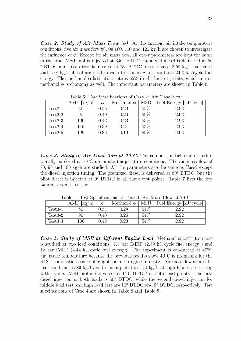
Case 2: Study of Air Mass Flow (φ): At the ambient air intake temperatureconditions, five air mass flow 80, 90 100, 110 and 120 kg/h are chosen to investigatethe influence of φ. Except for air mass flow, all other parameters are kept the samein the test. Methanol is injected at 340 BTDC, premixed diesel is delivered at 50 BTDC and pilot diesel is injected at 13 BTDC, respectively. 3.59 kg/h methanoland 1.38 kg/h diesel are used in each test point which contains 2.93 kJ/cycle fuelenergy. The methanol substitution rate is 55% in all the test points, which meansmethanol φ is changing as well. The important parameters are shown in Table 6.
Table 6: Test Specifications of Case 2: Air Mass FlowAMF [kg/h] φ Methanol φ MSR Fuel Energy [kJ/cycle]
Test2-1 80 0.55 0.29 55% 2.93Test2-2 90 0.49 0.26 55% 2.93Test2-3 100 0.42 0.23 55% 2.93Test2-4 110 0.39 0.21 55% 2.93Test2-5 120 0.36 0.19 55% 2.93
Case 3: Study of Air Mass flow at 70C: The combustion behaviour is addi-tionally explored at 70C air intake temperature conditions. The air mass flow of80, 90 and 100 kg/h are studied. All the parameters are the same as Case2 exceptthe diesel injection timing. The premixed diesel is delivered at 50 BTDC, but thepilot diesel is injected at 9 BTDC in all three test points. Table 7 lists the keyparameters of this case.
Table 7: Test Specifications of Case 3: Air Mass Flow at 70CAMF [kg/h] φ Methanol φ MSR Fuel Energy [kJ/cycle]
Test3-1 80 0.54 0.29 54% 2.92Test3-2 90 0.48 0.26 54% 2.92Test3-3 100 0.43 0.23 54% 2.92
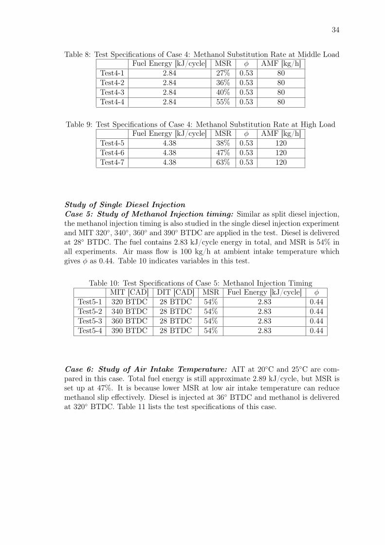
Case 4: Study of MSR at different Engine Load: Methanol substitution rateis studied at two load conditions: 7.5 bar IMEP (2.89 kJ/cycle fuel energy ) and12 bar IMEP (4.44 kJ/cycle fuel energy). The experiment is conducted at 40Cair intake temperature because the previous results show 40C is promising for theRCCI combustion concerning ignition and ringing intensity. Air mass flow at middleload condition is 80 kg/h, and it is adjusted to 120 kg/h at high load case to keepφ the same. Methanol is delivered at 340 BTDC in both load points. The firstdiesel injection in both loads is 50 BTDC, while the second diesel injection formiddle load test and high load test are 11 BTDC and 9 BTDC, respectively. Testspecifications of Case 4 are shown in Table 8 and Table 9.
34
Table 8: Test Specifications of Case 4: Methanol Substitution Rate at Middle LoadFuel Energy [kJ/cycle] MSR φ AMF [kg/h]
Test4-1 2.84 27% 0.53 80Test4-2 2.84 36% 0.53 80Test4-3 2.84 40% 0.53 80Test4-4 2.84 55% 0.53 80
Table 9: Test Specifications of Case 4: Methanol Substitution Rate at High LoadFuel Energy [kJ/cycle] MSR φ AMF [kg/h]
Test4-5 4.38 38% 0.53 120Test4-6 4.38 47% 0.53 120Test4-7 4.38 63% 0.53 120
Study of Single Diesel InjectionCase 5: Study of Methanol Injection timing: Similar as split diesel injection,the methanol injection timing is also studied in the single diesel injection experimentand MIT 320, 340, 360 and 390 BTDC are applied in the test. Diesel is deliveredat 28 BTDC. The fuel contains 2.83 kJ/cycle energy in total, and MSR is 54% inall experiments. Air mass flow is 100 kg/h at ambient intake temperature whichgives φ as 0.44. Table 10 indicates variables in this test.
Table 10: Test Specifications of Case 5: Methanol Injection TimingMIT [CAD] DIT [CAD] MSR Fuel Energy [kJ/cycle] φ
Test5-1 320 BTDC 28 BTDC 54% 2.83 0.44Test5-2 340 BTDC 28 BTDC 54% 2.83 0.44Test5-3 360 BTDC 28 BTDC 54% 2.83 0.44Test5-4 390 BTDC 28 BTDC 54% 2.83 0.44
Case 6: Study of Air Intake Temperature: AIT at 20C and 25C are com-pared in this case. Total fuel energy is still approximate 2.89 kJ/cycle, but MSR isset up at 47%. It is because lower MSR at low air intake temperature can reducemethanol slip effectively. Diesel is injected at 36 BTDC and methanol is deliveredat 320 BTDC. Table 11 lists the test specifications of this case.
35
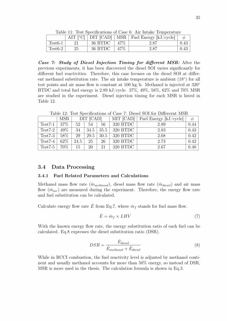
Table 11: Test Specifications of Case 6: Air Intake TemperatureAIT [C] DIT [CAD] MSR Fuel Energy [kJ/cycle] φ
Test6-1 21 36 BTDC 47% 2.87 0.43Test6-2 25 36 BTDC 47% 2.87 0.43
Case 7: Study of Diesel Injection Timing for different MSR: After theprevious experiments, it has been discovered the diesel SOI varies significantly fordifferent fuel reactivities. Therefore, this case focuses on the diesel SOI at differ-ent methanol substitution rate. The air intake temperature is ambient (18) for alltest points and air mass flow is constant at 100 kg/h. Methanol is injected at 320BTDC and total fuel energy is 2.89 kJ/cycle. 37%, 49%, 58%, 62% and 70% MSRare studied in the experiment. Diesel injection timing for each MSR is listed inTable 12.
Table 12: Test Specifications of Case 7: Diesel SOI for Differernt MSRMSR DIT [CAD] MIT [CAD] Fuel Energy [kJ/cycle] φ
Test7-1 37% 52 54 56 320 BTDC 2.89 0.44Test7-2 49% 34 34.5 35.5 320 BTDC 2.83 0.43Test7-3 58% 29 29.5 30.5 320 BTDC 2.68 0.42Test7-4 62% 24.5 25 26 320 BTDC 2.73 0.42Test7-5 70% 15 20 21 320 BTDC 2.67 0.40
3.4 Data Processing
3.4.1 Fuel Related Parameters and Calculations
Methanol mass flow rate (mmethanol), diesel mass flow rate (mdiesel) and air massflow (mair) are measured during the experiment. Therefore, the energy flow rateand fuel substitution can be calculated.
Calculate energy flow rate E from Eq.7, where mf stands for fuel mass flow.
E = mf × LHV (7)
With the known energy flow rate, the energy substitution ratio of each fuel can becalculated. Eq.8 expresses the diesel substitution ratio (DSR).
DSR =Ediesel
Emethanol + Ediesel
(8)
While in RCCI combustion, the fuel reactivity level is adjusted by methanol conti-nent and usually methanol accounts for more than 50% energy, so instead of DSR,MSR is more used in the thesis. The calculation formula is shown in Eq.3.
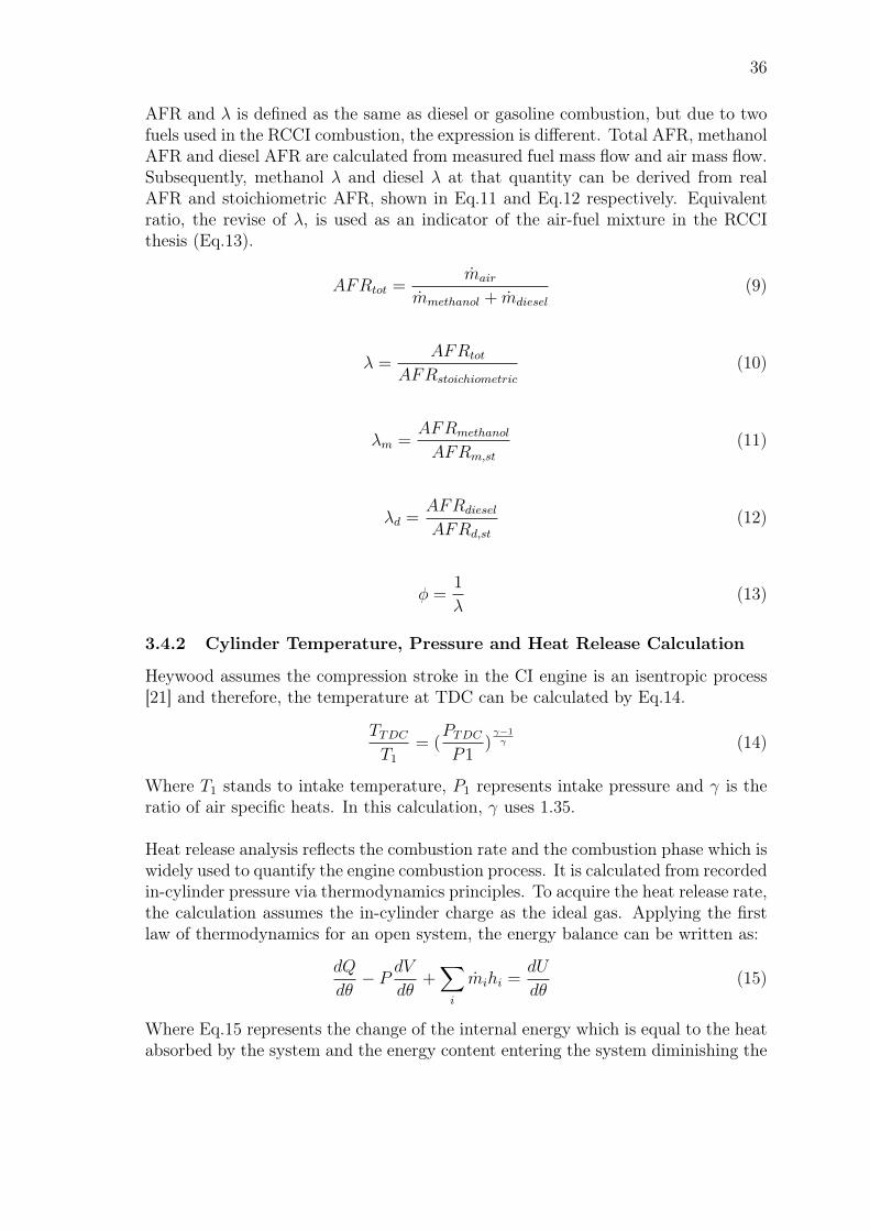
36
AFR and λ is defined as the same as diesel or gasoline combustion, but due to twofuels used in the RCCI combustion, the expression is different. Total AFR, methanolAFR and diesel AFR are calculated from measured fuel mass flow and air mass flow.Subsequently, methanol λ and diesel λ at that quantity can be derived from realAFR and stoichiometric AFR, shown in Eq.11 and Eq.12 respectively. Equivalentratio, the revise of λ, is used as an indicator of the air-fuel mixture in the RCCIthesis (Eq.13).
AFRtot =mair
mmethanol + mdiesel
(9)
λ =AFRtot
AFRstoichiometric
(10)
λm =AFRmethanol
AFRm,st
(11)
λd =AFRdiesel
AFRd,st
(12)
φ =1
λ(13)
3.4.2 Cylinder Temperature, Pressure and Heat Release Calculation
Heywood assumes the compression stroke in the CI engine is an isentropic process[21] and therefore, the temperature at TDC can be calculated by Eq.14.
TTDC
T1= (
PTDC
P1)γ−1γ (14)
Where T1 stands to intake temperature, P1 represents intake pressure and γ is theratio of air specific heats. In this calculation, γ uses 1.35.
Heat release analysis reflects the combustion rate and the combustion phase which iswidely used to quantify the engine combustion process. It is calculated from recordedin-cylinder pressure via thermodynamics principles. To acquire the heat release rate,the calculation assumes the in-cylinder charge as the ideal gas. Applying the firstlaw of thermodynamics for an open system, the energy balance can be written as:
dQ
dθ− P dV
dθ+∑i
mihi =dU
dθ(15)
Where Eq.15 represents the change of the internal energy which is equal to the heatabsorbed by the system and the energy content entering the system diminishing the
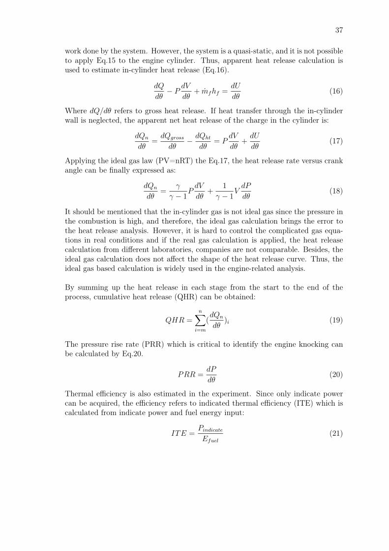
37
work done by the system. However, the system is a quasi-static, and it is not possibleto apply Eq.15 to the engine cylinder. Thus, apparent heat release calculation isused to estimate in-cylinder heat release (Eq.16).
dQ
dθ− P dV
dθ+ mfhf =
dU
dθ(16)
Where dQ/dθ refers to gross heat release. If heat transfer through the in-cylinderwall is neglected, the apparent net heat release of the charge in the cylinder is:
dQn
dθ=dQgross
dθ− dQht
dθ= P
dV
dθ+dU
dθ(17)
Applying the ideal gas law (PV=nRT) the Eq.17, the heat release rate versus crankangle can be finally expressed as:
dQn
dθ=
γ
γ − 1PdV
dθ+
1
γ − 1VdP
dθ(18)
It should be mentioned that the in-cylinder gas is not ideal gas since the pressure inthe combustion is high, and therefore, the ideal gas calculation brings the error tothe heat release analysis. However, it is hard to control the complicated gas equa-tions in real conditions and if the real gas calculation is applied, the heat releasecalculation from different laboratories, companies are not comparable. Besides, theideal gas calculation does not affect the shape of the heat release curve. Thus, theideal gas based calculation is widely used in the engine-related analysis.
By summing up the heat release in each stage from the start to the end of theprocess, cumulative heat release (QHR) can be obtained:
QHR =n∑
i=m
(dQn
dθ)i (19)
The pressure rise rate (PRR) which is critical to identify the engine knocking canbe calculated by Eq.20.
PRR =dP
dθ(20)
Thermal efficiency is also estimated in the experiment. Since only indicate powercan be acquired, the efficiency refers to indicated thermal efficiency (ITE) which iscalculated from indicate power and fuel energy input:
ITE =Pindicate
Efuel
(21)
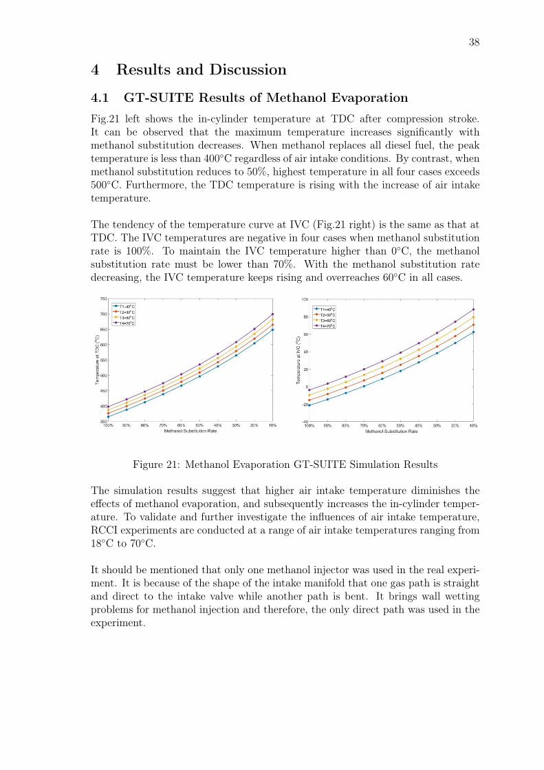
38
4 Results and Discussion
4.1 GT-SUITE Results of Methanol Evaporation
Fig.21 left shows the in-cylinder temperature at TDC after compression stroke.It can be observed that the maximum temperature increases significantly withmethanol substitution decreases. When methanol replaces all diesel fuel, the peaktemperature is less than 400C regardless of air intake conditions. By contrast, whenmethanol substitution reduces to 50%, highest temperature in all four cases exceeds500C. Furthermore, the TDC temperature is rising with the increase of air intaketemperature.
The tendency of the temperature curve at IVC (Fig.21 right) is the same as that atTDC. The IVC temperatures are negative in four cases when methanol substitutionrate is 100%. To maintain the IVC temperature higher than 0C, the methanolsubstitution rate must be lower than 70%. With the methanol substitution ratedecreasing, the IVC temperature keeps rising and overreaches 60C in all cases.
Figure 21: Methanol Evaporation GT-SUITE Simulation Results
The simulation results suggest that higher air intake temperature diminishes theeffects of methanol evaporation, and subsequently increases the in-cylinder temper-ature. To validate and further investigate the influences of air intake temperature,RCCI experiments are conducted at a range of air intake temperatures ranging from18C to 70C.
It should be mentioned that only one methanol injector was used in the real experi-ment. It is because of the shape of the intake manifold that one gas path is straightand direct to the intake valve while another path is bent. It brings wall wettingproblems for methanol injection and therefore, the only direct path was used in theexperiment.
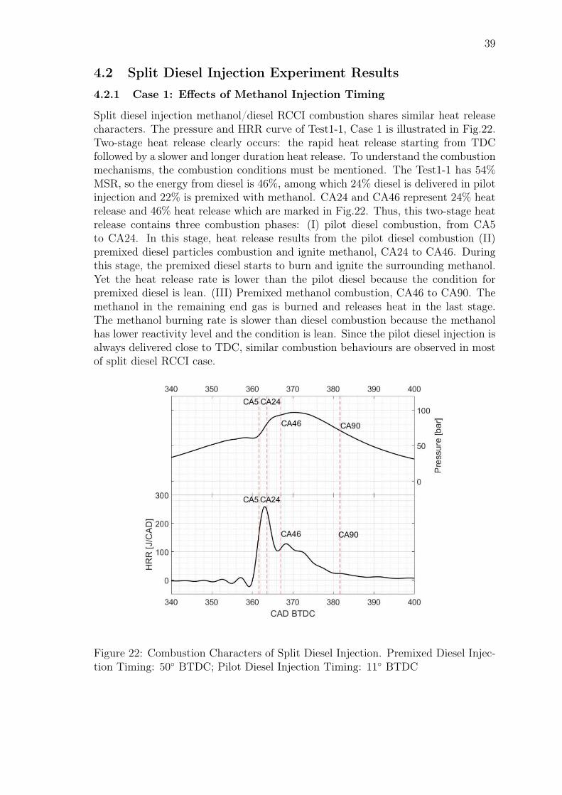
39
4.2 Split Diesel Injection Experiment Results
4.2.1 Case 1: Effects of Methanol Injection Timing
Split diesel injection methanol/diesel RCCI combustion shares similar heat releasecharacters. The pressure and HRR curve of Test1-1, Case 1 is illustrated in Fig.22.Two-stage heat release clearly occurs: the rapid heat release starting from TDCfollowed by a slower and longer duration heat release. To understand the combustionmechanisms, the combustion conditions must be mentioned. The Test1-1 has 54%MSR, so the energy from diesel is 46%, among which 24% diesel is delivered in pilotinjection and 22% is premixed with methanol. CA24 and CA46 represent 24% heatrelease and 46% heat release which are marked in Fig.22. Thus, this two-stage heatrelease contains three combustion phases: (I) pilot diesel combustion, from CA5to CA24. In this stage, heat release results from the pilot diesel combustion (II)premixed diesel particles combustion and ignite methanol, CA24 to CA46. Duringthis stage, the premixed diesel starts to burn and ignite the surrounding methanol.Yet the heat release rate is lower than the pilot diesel because the condition forpremixed diesel is lean. (III) Premixed methanol combustion, CA46 to CA90. Themethanol in the remaining end gas is burned and releases heat in the last stage.The methanol burning rate is slower than diesel combustion because the methanolhas lower reactivity level and the condition is lean. Since the pilot diesel injection isalways delivered close to TDC, similar combustion behaviours are observed in mostof split diesel RCCI case.
Figure 22: Combustion Characters of Split Diesel Injection. Premixed Diesel Injec-tion Timing: 50 BTDC; Pilot Diesel Injection Timing: 11 BTDC
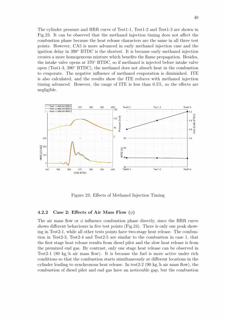
40
The cylinder pressure and HRR curve of Test1-1, Test1-2 and Test1-3 are shown inFig.23. It can be observed that the methanol injection timing does not affect thecombustion phase because the heat release characters are the same in all three testpoints. However, CA5 is more advanced in early methanol injection case and theignition delay in 390 BTDC is the shortest. It is because early methanol injectioncreates a more homogeneous mixture which benefits the flame propagation. Besides,the intake valve opens at 370 BTDC, so if methanol is injected before intake valveopen (Test1-3, 390 BTDC), the methanol does not absorb heat in the combustionto evaporate. The negative influence of methanol evaporation is diminished. ITEis also calculated, and the results show the ITE reduces with methanol injectiontiming advanced. However, the range of ITE is less than 0.5%, so the effects arenegligible.
Figure 23: Effects of Methanol Injection Timing
4.2.2 Case 2: Effects of Air Mass Flow (φ)
The air mass flow or φ influence combustion phase directly, since the HRR curveshows different behaviours in five test points (Fig.24). There is only one peak show-ing in Test2-1, while all other tests points have two-stage heat release. The combus-tion in Test2-3, Test2-4 and Test2-5 are similar to the combustion in case 1, thatthe first stage heat release results from diesel pilot and the slow heat release is fromthe premixed end gas. By contrast, only one stage heat release can be observed inTest2-1 (80 kg/h air mass flow). It is because the fuel is more active under richconditions so that the combustion starts simultaneously at different locations in thecylinder leading to synchronous heat release. In test2-2 (90 kg/h air mass flow), thecombustion of diesel pilot and end gas have an noticeable gap, but the combustion
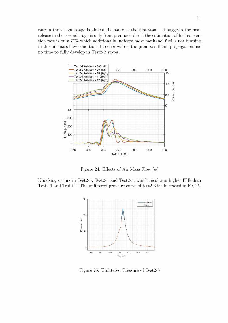
41
rate in the second stage is almost the same as the first stage. It suggests the heatrelease in the second stage is only from premixed diesel the estimation of fuel conver-sion rate is only 77% which additionally indicate most methanol fuel is not burningin this air mass flow condition. In other words, the premixed flame propagation hasno time to fully develop in Test2-2 states.
Figure 24: Effects of Air Mass Flow (φ)
Knocking occurs in Test2-3, Test2-4 and Test2-5, which results in higher ITE thanTest2-1 and Test2-2. The unfiltered pressure curve of test2-3 is illustrated in Fig.25.
Figure 25: Unfiltered Pressure of Test2-3
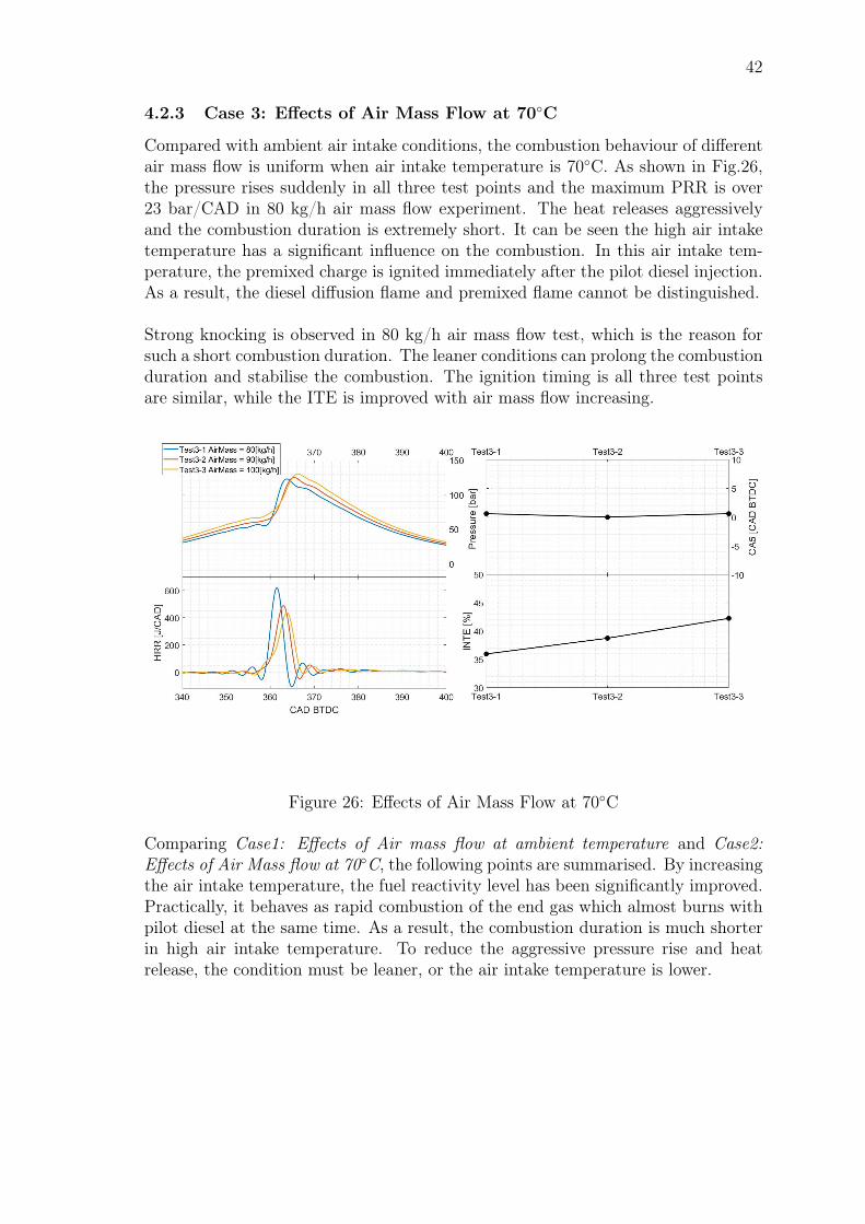
42
4.2.3 Case 3: Effects of Air Mass Flow at 70C
Compared with ambient air intake conditions, the combustion behaviour of differentair mass flow is uniform when air intake temperature is 70C. As shown in Fig.26,the pressure rises suddenly in all three test points and the maximum PRR is over23 bar/CAD in 80 kg/h air mass flow experiment. The heat releases aggressivelyand the combustion duration is extremely short. It can be seen the high air intaketemperature has a significant influence on the combustion. In this air intake tem-perature, the premixed charge is ignited immediately after the pilot diesel injection.As a result, the diesel diffusion flame and premixed flame cannot be distinguished.
Strong knocking is observed in 80 kg/h air mass flow test, which is the reason forsuch a short combustion duration. The leaner conditions can prolong the combustionduration and stabilise the combustion. The ignition timing is all three test pointsare similar, while the ITE is improved with air mass flow increasing.
Figure 26: Effects of Air Mass Flow at 70C
Comparing Case1: Effects of Air mass flow at ambient temperature and Case2:Effects of Air Mass flow at 70C, the following points are summarised. By increasingthe air intake temperature, the fuel reactivity level has been significantly improved.Practically, it behaves as rapid combustion of the end gas which almost burns withpilot diesel at the same time. As a result, the combustion duration is much shorterin high air intake temperature. To reduce the aggressive pressure rise and heatrelease, the condition must be leaner, or the air intake temperature is lower.

43
4.2.4 Case 4: Effects of MSR at different Engine Load
The effects of methanol substitution rate are investigated in both middle load andhigh load conditions. The middle load refers to around 40% of the full load of LEO1which corresponds to 2.89 kJ/cycle fuel energy and the high load indicates the 70%of the full load of LEO1 which contains 4.44 kJ/cycle fuel energy. As shown inFig.27, the combustion behaviour is very different in high load experiments whereclear premixed flame propagation can be seen. In Test4-5, Test4-6 and Test4-7,the combustion of diesel pilot results in the first stage heat release. It also ignitesthe premixed charge which contains both methanol and diesel leading to the secondstage heat release. The heat release from the premixed charge is rapid in high loadtests because the methanol is mixed homogeneously so that the combustion startssimultaneously at different locations. Besides, the φ in this group of the experimentis 0.55, so the condition is relatively rich. Thus, the premixed charge shows rapidcombustion behaviour instead of slow and long duration combustion demonstratedin Fig.22 Additionally, the combustion is retarded with MSR increases and higherpressure is reached in high MSR test points.
While in middle load conditions, the premixed flame propagation can be distin-guished clearer in high MSR tests, especially in Test4-4. It is because when MSR islow, the methanol continent entering diesel diffusion flame regions and the combus-tion is similar to diesel combustion. When the MSR increases, the second stage heatrelease is governed by the methanol component. Same as high load experiment, thecombustion is retarded and ignition delay is increased with increasing of MSR.
Figure 27: Effects of MSR at Different Engine Load
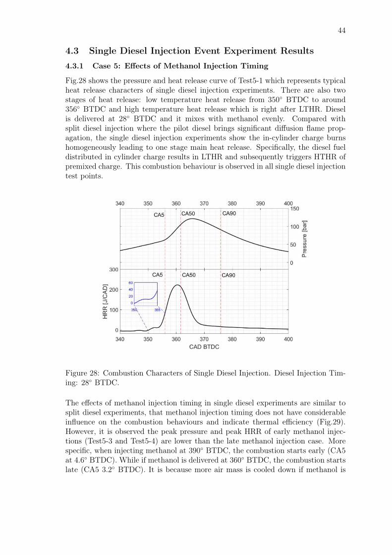
44
4.3 Single Diesel Injection Event Experiment Results
4.3.1 Case 5: Effects of Methanol Injection Timing
Fig.28 shows the pressure and heat release curve of Test5-1 which represents typicalheat release characters of single diesel injection experiments. There are also twostages of heat release: low temperature heat release from 350 BTDC to around356 BTDC and high temperature heat release which is right after LTHR. Dieselis delivered at 28 BTDC and it mixes with methanol evenly. Compared withsplit diesel injection where the pilot diesel brings significant diffusion flame prop-agation, the single diesel injection experiments show the in-cylinder charge burnshomogeneously leading to one stage main heat release. Specifically, the diesel fueldistributed in cylinder charge results in LTHR and subsequently triggers HTHR ofpremixed charge. This combustion behaviour is observed in all single diesel injectiontest points.
Figure 28: Combustion Characters of Single Diesel Injection. Diesel Injection Tim-ing: 28 BTDC.
The effects of methanol injection timing in single diesel experiments are similar tosplit diesel experiments, that methanol injection timing does not have considerableinfluence on the combustion behaviours and indicate thermal efficiency (Fig.29).However, it is observed the peak pressure and peak HRR of early methanol injec-tions (Test5-3 and Test5-4) are lower than the late methanol injection case. Morespecific, when injecting methanol at 390 BTDC, the combustion starts early (CA5at 4.6 BTDC). While if methanol is delivered at 360 BTDC, the combustion startslate (CA5 3.2 BTDC). It is because more air mass is cooled down if methanol is
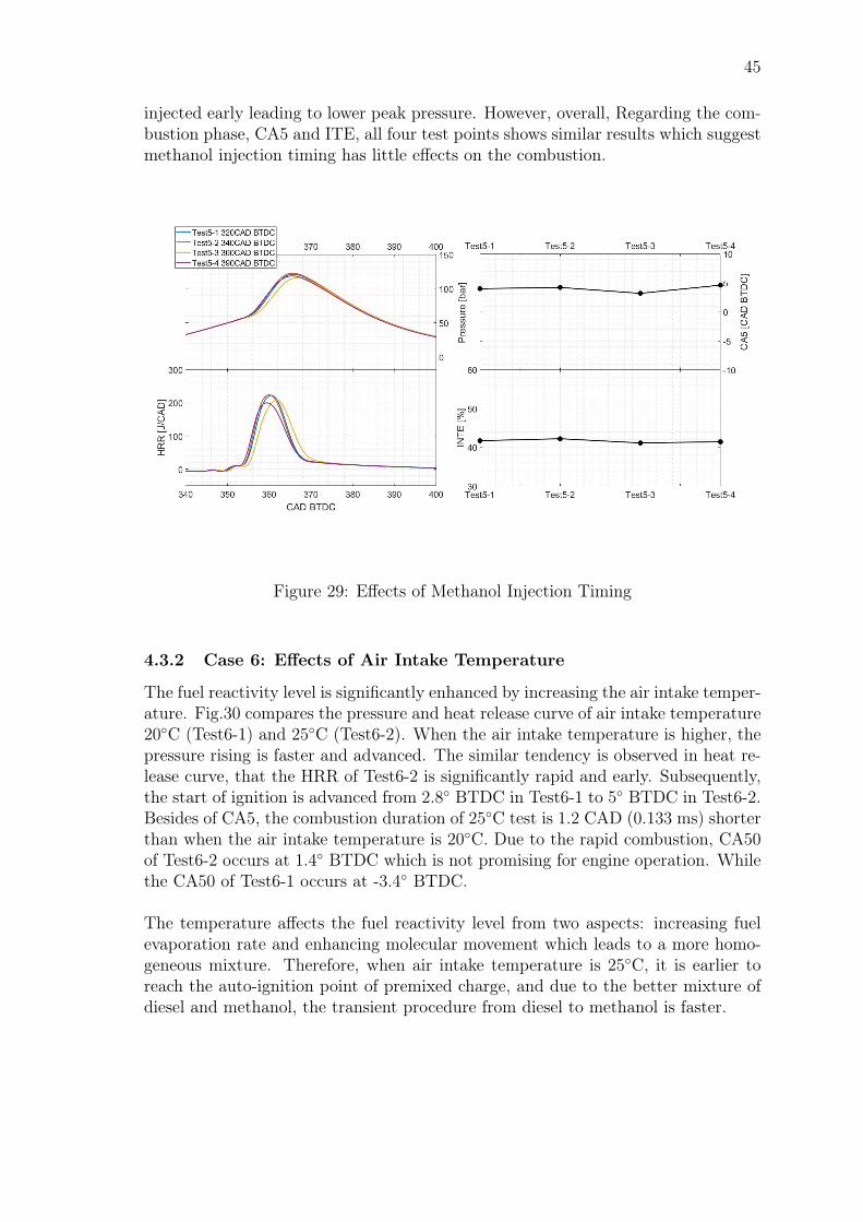
45
injected early leading to lower peak pressure. However, overall, Regarding the com-bustion phase, CA5 and ITE, all four test points shows similar results which suggestmethanol injection timing has little effects on the combustion.
Figure 29: Effects of Methanol Injection Timing
4.3.2 Case 6: Effects of Air Intake Temperature
The fuel reactivity level is significantly enhanced by increasing the air intake temper-ature. Fig.30 compares the pressure and heat release curve of air intake temperature20C (Test6-1) and 25C (Test6-2). When the air intake temperature is higher, thepressure rising is faster and advanced. The similar tendency is observed in heat re-lease curve, that the HRR of Test6-2 is significantly rapid and early. Subsequently,the start of ignition is advanced from 2.8 BTDC in Test6-1 to 5 BTDC in Test6-2.Besides of CA5, the combustion duration of 25C test is 1.2 CAD (0.133 ms) shorterthan when the air intake temperature is 20C. Due to the rapid combustion, CA50of Test6-2 occurs at 1.4 BTDC which is not promising for engine operation. Whilethe CA50 of Test6-1 occurs at -3.4 BTDC.
The temperature affects the fuel reactivity level from two aspects: increasing fuelevaporation rate and enhancing molecular movement which leads to a more homo-geneous mixture. Therefore, when air intake temperature is 25C, it is earlier toreach the auto-ignition point of premixed charge, and due to the better mixture ofdiesel and methanol, the transient procedure from diesel to methanol is faster.
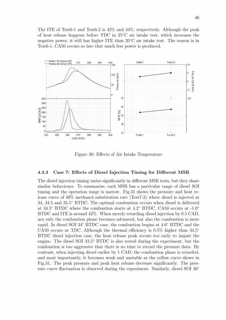
46
The ITE of Test6-1 and Test6-2 is 42% and 44%, respectively. Although the peakof heat release happens before TDC in 25C air intake test, which increases thenegative power, it still has higher ITE than 20C air intake test. The reason is inTest6-1, CA50 occurs so late that much less power is produced.
Figure 30: Effects of Air Intake Temperature
4.3.3 Case 7: Effects of Diesel Injection Timing for Different MSR
The diesel injection timing varies significantly in different MSR tests, but they sharesimilar behaviours. To summarise, each MSR has a particular range of diesel SOItiming and the operation range is narrow. Fig.31 shows the pressure and heat re-lease curve of 49% methanol substitution rate (Test7-2) where diesel is injected at34, 34.5 and 35.5 BTDC. The optimal combustion occurs when diesel is deliveredat 34.5 BTDC where the combustion starts at 4.2 BTDC, CA50 occurs at -1.0BTDC and ITE is around 42%. When merely retarding diesel injection by 0.5 CAD,not only the combustion phase becomes advanced, but also the combustion is morerapid. In diesel SOI 34 BTDC case, the combustion begins at 4.6 BTDC and theCA50 occurs at TDC. Although the thermal efficiency is 0.5% higher than 34.5BTDC diesel injection case, the heat release peak occurs too early to impair theengine. The diesel SOI 33.5 BTDC is also tested during the experiment, but thecombustion is too aggressive that there is no time to record the pressure data. Bycontrast, when injecting diesel earlier by 1 CAD, the combustion phase is retarded,and most importantly, it becomes weak and unstable as the yellow curve shows inFig.31. The peak pressure and peak heat release decrease significantly. The pres-sure curve fluctuation is observed during the experiment. Similarly, diesel SOI 36
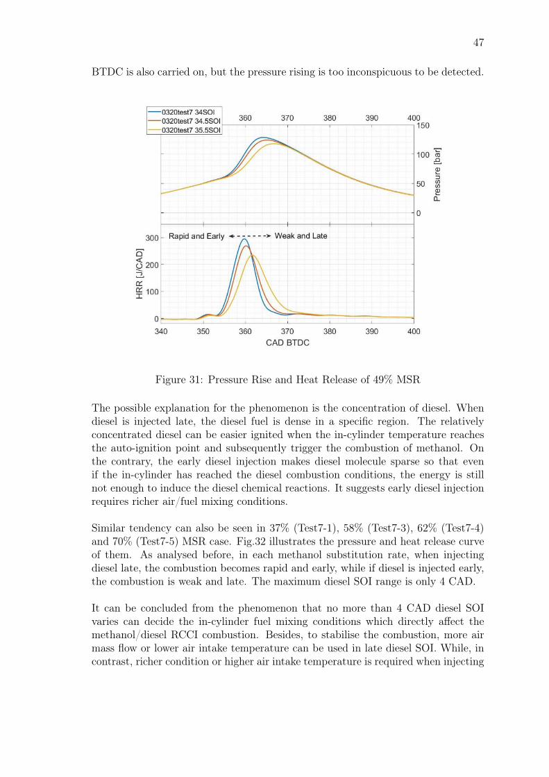
47
BTDC is also carried on, but the pressure rising is too inconspicuous to be detected.
Figure 31: Pressure Rise and Heat Release of 49% MSR
The possible explanation for the phenomenon is the concentration of diesel. Whendiesel is injected late, the diesel fuel is dense in a specific region. The relativelyconcentrated diesel can be easier ignited when the in-cylinder temperature reachesthe auto-ignition point and subsequently trigger the combustion of methanol. Onthe contrary, the early diesel injection makes diesel molecule sparse so that evenif the in-cylinder has reached the diesel combustion conditions, the energy is stillnot enough to induce the diesel chemical reactions. It suggests early diesel injectionrequires richer air/fuel mixing conditions.
Similar tendency can also be seen in 37% (Test7-1), 58% (Test7-3), 62% (Test7-4)and 70% (Test7-5) MSR case. Fig.32 illustrates the pressure and heat release curveof them. As analysed before, in each methanol substitution rate, when injectingdiesel late, the combustion becomes rapid and early, while if diesel is injected early,the combustion is weak and late. The maximum diesel SOI range is only 4 CAD.
It can be concluded from the phenomenon that no more than 4 CAD diesel SOIvaries can decide the in-cylinder fuel mixing conditions which directly affect themethanol/diesel RCCI combustion. Besides, to stabilise the combustion, more airmass flow or lower air intake temperature can be used in late diesel SOI. While, incontrast, richer condition or higher air intake temperature is required when injecting
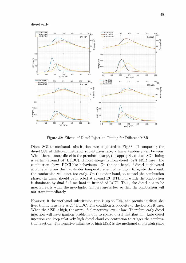
48
diesel early.
Figure 32: Effects of Diesel Injection Timing for Different MSR
Diesel SOI to methanol substitution rate is plotted in Fig.33. If comparing thediesel SOI at different methanol substitution rate, a linear tendency can be seen.When there is more diesel in the premixed charge, the appropriate diesel SOI timingis earlier (around 54 BTDC). If most energy is from diesel (37% MSR case), thecombustion shows HCCI-like behaviours. On the one hand, if diesel is delivereda bit later when the in-cylinder temperature is high enough to ignite the diesel,the combustion will start too early. On the other hand, to control the combustionphase, the diesel should be injected at around 13 BTDC in which the combustionis dominant by dual fuel mechanism instead of RCCI. Thus, the diesel has to beinjected early when the in-cylinder temperature is low so that the combustion willnot start immediately.
However, if the methanol substitution rate is up to 70%, the promising diesel de-liver timing is as late as 20 BTDC. The condition is opposite to the low MSR case.When the MSR is high, the overall fuel reactivity level is low. Therefore, early dieselinjection will have ignition problems due to sparse diesel distribution. Late dieselinjection can keep relatively high diesel cloud concentration to trigger the combus-tion reaction. The negative influence of high MSR is the methanol slip is high since
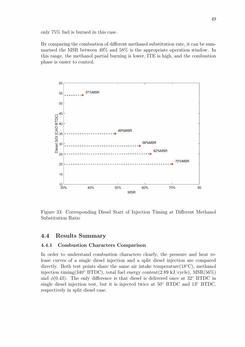
49
only 75% fuel is burned in this case.
By comparing the combustion of different methanol substitution rate, it can be sum-marised the MSR between 49% and 58% is the appropriate operation window. Inthis range, the methanol partial burning is lower, ITE is high, and the combustionphase is easier to control.
Figure 33: Corresponding Diesel Start of Injection Timing at Different MethanolSubstitution Ratio
4.4 Results Summary
4.4.1 Combustion Characters Comparison
In order to understand combustion characters clearly, the pressure and heat re-lease curves of a single diesel injection and a split diesel injection are compareddirectly. Both test points share the same air intake temperature(18C), methanolinjection timing(340 BTDC), total fuel energy content(2.89 kJ/cycle), MSR(56%)and φ(0.43). The only difference is that diesel is delivered once at 32 BTDC insingle diesel injection test, but it is injected twice at 50 BTDC and 13 BTDC,respectively in split diesel case.
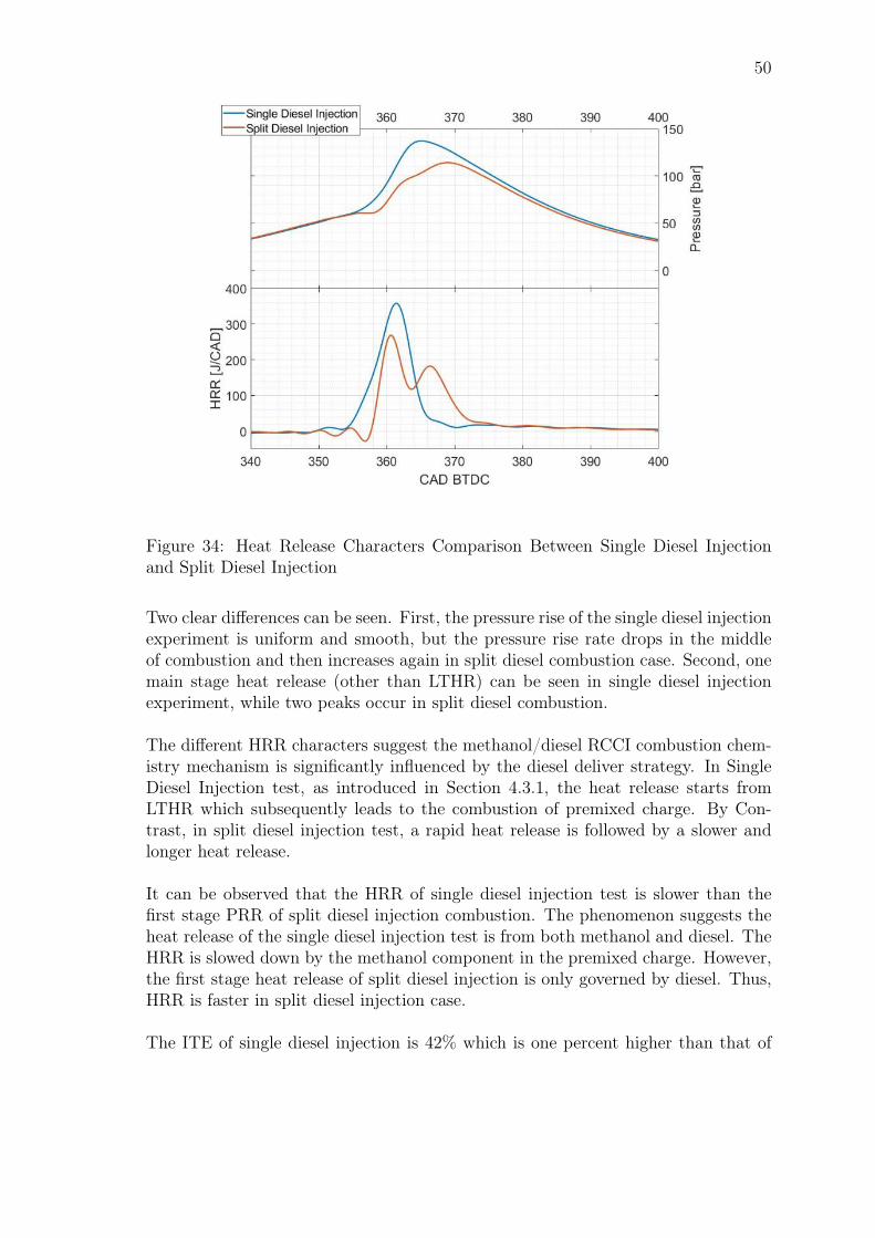
50
Figure 34: Heat Release Characters Comparison Between Single Diesel Injectionand Split Diesel Injection
Two clear differences can be seen. First, the pressure rise of the single diesel injectionexperiment is uniform and smooth, but the pressure rise rate drops in the middleof combustion and then increases again in split diesel combustion case. Second, onemain stage heat release (other than LTHR) can be seen in single diesel injectionexperiment, while two peaks occur in split diesel combustion.
The different HRR characters suggest the methanol/diesel RCCI combustion chem-istry mechanism is significantly influenced by the diesel deliver strategy. In SingleDiesel Injection test, as introduced in Section 4.3.1, the heat release starts fromLTHR which subsequently leads to the combustion of premixed charge. By Con-trast, in split diesel injection test, a rapid heat release is followed by a slower andlonger heat release.
It can be observed that the HRR of single diesel injection test is slower than thefirst stage PRR of split diesel injection combustion. The phenomenon suggests theheat release of the single diesel injection test is from both methanol and diesel. TheHRR is slowed down by the methanol component in the premixed charge. However,the first stage heat release of split diesel injection is only governed by diesel. Thus,HRR is faster in split diesel injection case.
The ITE of single diesel injection is 42% which is one percent higher than that of
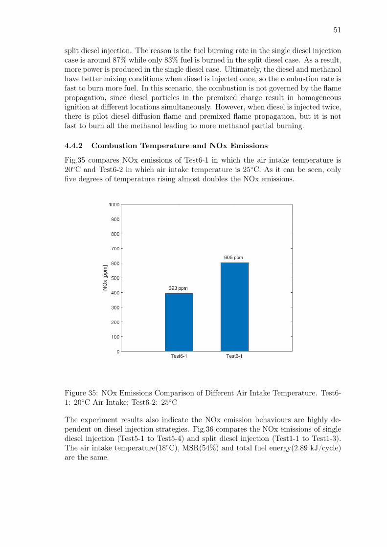
51
split diesel injection. The reason is the fuel burning rate in the single diesel injectioncase is around 87% while only 83% fuel is burned in the split diesel case. As a result,more power is produced in the single diesel case. Ultimately, the diesel and methanolhave better mixing conditions when diesel is injected once, so the combustion rate isfast to burn more fuel. In this scenario, the combustion is not governed by the flamepropagation, since diesel particles in the premixed charge result in homogeneousignition at different locations simultaneously. However, when diesel is injected twice,there is pilot diesel diffusion flame and premixed flame propagation, but it is notfast to burn all the methanol leading to more methanol partial burning.
4.4.2 Combustion Temperature and NOx Emissions
Fig.35 compares NOx emissions of Test6-1 in which the air intake temperature is20C and Test6-2 in which air intake temperature is 25C. As it can be seen, onlyfive degrees of temperature rising almost doubles the NOx emissions.
Figure 35: NOx Emissions Comparison of Different Air Intake Temperature. Test6-1: 20C Air Intake; Test6-2: 25C
The experiment results also indicate the NOx emission behaviours are highly de-pendent on diesel injection strategies. Fig.36 compares the NOx emissions of singlediesel injection (Test5-1 to Test5-4) and split diesel injection (Test1-1 to Test1-3).The air intake temperature(18C), MSR(54%) and total fuel energy(2.89 kJ/cycle)are the same.
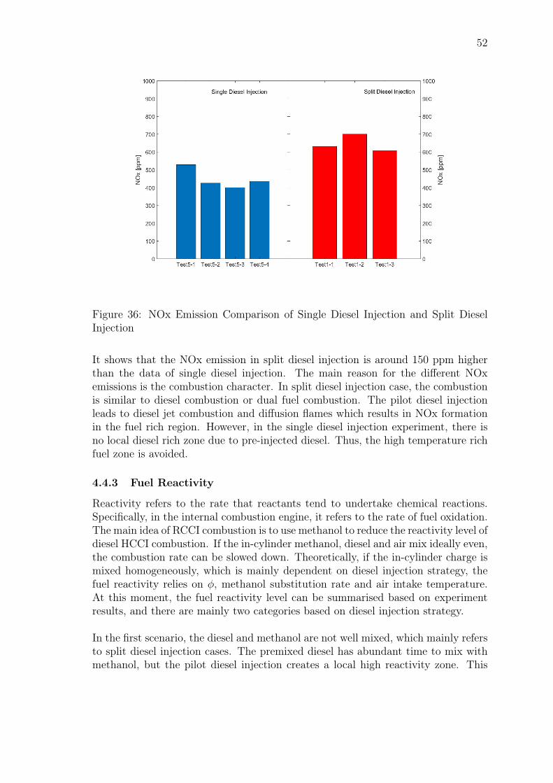
52
Figure 36: NOx Emission Comparison of Single Diesel Injection and Split DieselInjection
It shows that the NOx emission in split diesel injection is around 150 ppm higherthan the data of single diesel injection. The main reason for the different NOxemissions is the combustion character. In split diesel injection case, the combustionis similar to diesel combustion or dual fuel combustion. The pilot diesel injectionleads to diesel jet combustion and diffusion flames which results in NOx formationin the fuel rich region. However, in the single diesel injection experiment, there isno local diesel rich zone due to pre-injected diesel. Thus, the high temperature richfuel zone is avoided.
4.4.3 Fuel Reactivity
Reactivity refers to the rate that reactants tend to undertake chemical reactions.Specifically, in the internal combustion engine, it refers to the rate of fuel oxidation.The main idea of RCCI combustion is to use methanol to reduce the reactivity level ofdiesel HCCI combustion. If the in-cylinder methanol, diesel and air mix ideally even,the combustion rate can be slowed down. Theoretically, if the in-cylinder charge ismixed homogeneously, which is mainly dependent on diesel injection strategy, thefuel reactivity relies on φ, methanol substitution rate and air intake temperature.At this moment, the fuel reactivity level can be summarised based on experimentresults, and there are mainly two categories based on diesel injection strategy.
In the first scenario, the diesel and methanol are not well mixed, which mainly refersto split diesel injection cases. The premixed diesel has abundant time to mix withmethanol, but the pilot diesel injection creates a local high reactivity zone. This
53
diesel rich zone results in diesel combustion and diffusion flame propagation. Themethanol reactivity control is mainly reflected in the premixed charge combustionstage where there is premixed flame propagation. The premixed diesel is deliveredvery early so that diesel and methanol can be regarded as homogeneous mixing.Thus, there is a clear reactivity stratification in the split diesel case: the high reac-tivity diesel pilot zone and reactivity controlled premixed region. As shown in theexperiment results, the combustion is dominated by the pilot diesel injection becausethe split diesel RCCI shows dual fuel or diesel combustion characters including highNOx and high combustion temperature.
In the second scenario, the mixing condition of diesel and methanol can be assumedhomogeneously, which is represented by single diesel injection cases. According toCase 6: Study of Air Intake Temperature, the RCCI fuel reactivity is directly af-fected by the charge air temperature. It is because the high temperature increasesthe fuel internal energy so that the fuel is more accessible to be ignited. Besides,high methanol substitution rate reduces the fuel reactivity. It is supported by theexperiment phenomenon that the methanol incomplete burning is significant in highMSR case. For example, in Test7-4 and Test7-5 that have higher than 60% MSR,considerable methanol partial burning is observed. However, the experiment doesnot reach the ideal methanol/diesel mixing condition since the diesel cloud concen-tration has the influence on the combustion. As analysed in Section 4.3.3, the dieselSOI timing affects the diesel fuel distribution in the premixed charge which furtherinfluences the combustion.
54
5 ConclusionsThe thesis systematically studied the RCCI combustion principles and reviewed theprevious works. Based on the literature study, the critical parameters of methanol/dieselRCCI combustion has been identified, and the experiment has tested a wide range ofvariables. Combustion characteristics are analysed via the recorded pressure curveand heat release curve.
Theoretically, RCCI combustion requires diesel and methanol to mix homogeneously,but in practical, the ideal homogeneous mixture condition is tough to reach. Thecombustion starts with diesel particles which further ignite methanol. Most of thecurrent RCCI researches inject diesel earlier than 15 BTDC to reach RCCI likecombustion, and in order to stabilise the combustion, diesel injection is always split.However, researchers have different understanding to RCCI technology due to in-sufficient research, and thus, many RCCI combustion researches show either dualfuel like behaviours or the combustion starts too early for engines. In this masterthesis, to achieve the study objective, the experiment attempts to measure air massflow, air intake temperature, methanol substitution rate, methanol injection timingand diesel injection strategy. The master thesis tries to investigate how to reach thetheoretical RCCI combustion, the experiments results are presented in Chapter 4and the key points are concluded in the following paragraphs.
The combustion mechanism is the fundamental factor to distinguish RCCI combus-tion and dual fuel combustion. To reach the RCCI combustion zone, the air intaketemperature is required to be high. As the results of GT-SUITE simulation sug-gest, air intake temperature greater than 40C is necessary to diminish the effectsof methanol evaporation. A research conducted in King Abdullah University of Sci-ence and Technology even used 200C air intake temperature. Additionally, it isillustrated by the experiment that the methanol/diesel RCCI combustion can be di-vided into two groups according to the combustion behaviour. Practically, the dieselinjection strategy has a great influence on the combustion mechanism, because itdecides the fuel reactivity stratification. Accordingly, the thesis experiment can bedivided into two groups: (1) Split diesel injection experiment where it has dual fuelcombustion behaviours. The combustion starts from pilot diesel ignition followedby pilot diesel diffusion flame propagation and premixed end gas combustion; (2)Single diesel injection that results in RCCI combustion. The diesel diffusion flamedoes not occur and the combustion starts from LTHR which is followed by simul-taneous combustion of the premixed charge. Other than the combustion character,the influence of parameters in each group can be summarised:
(1) Split diesel injection
• Methanol injection timing does not have significant influences on the methanol/dieselcombustion concerning combustion phase, ITE and NOx emissions.
• Air mass flow affects premixed flame propagation directly. There is no com-
55
plete premixed flame propagation observed in rich conditions when the equiv-alent ratio is lower than 0.42 (Air mass flow 80 kg/h and 90 kg/h).
• Air intake temperature strongly actives the combustion. 70C air intake tem-perature leads to early, rapid combustion and single stage heat release.
• Methanol substitution rate is discovered in middle load (IMEP: 7.5 bar) andhigh load (IMEP: 12 bar). Premixed flame propagation has taken place inhigh load case, since two heat release peak occurs. While there is no explicitpremixed flame propagation in middle load conditions, especially when MSRis lower than 56%. Besides, it is observed combustion is retarded with MSRincreasing.
(2) Single diesel injection
• Methanol injection timing of the single diesel injection experiment has similarbehaviour as split diesel case that it does not affect the combustion signifi-cantly.
• Air intake temperature strongly actives the combustion. Increasing air intaketemperature from 20C to 25C, the CA50 advanced from -3.5 BTDC to 0.2BTDC.
• Methanol substitution rate has great influence on the RCCI combustion and itdecides diesel SOI timing directly. For a particular MSR, there is a certain andnarrow diesel SOI range. Besides, if MSR is lower than 30%, the combustionis hard to control and the advantages of RCCI cannot be seen. While if MSRhigher than 70%, the partial combustion is significant. Thus, the optimal MSRused in the experiment is between 47% to 58%.
To summarise, the optimal conditions to operate methanol/diesel fuel in RCCI con-dition is 45% to 60% MSR, 30C to 50C air intake temperature and around 35BTDC diesel injection timing.
56
6 Future WorkIn order to reach theoretical RCCI combustion conditions, single diesel injectionstrategy or split diesel injection with delivering pilot diesel earlier than 15 BTDCshould be conducted.
Upon this injection strategy, at a certain methanol substitution rate, there are twoaspects of studying the equivalent ratio: the bottom limit in lean conditions of mis-fire and up limit in rich conditions of diesel components early combustion. Misfirecan be prevented by increasing the air intake temperature, but high air intake tem-perature will result in premixed fuel early combustion. To balance the influenceof air intake temperature, it is necessary to investigate the impact of EGR. Addi-tionally, the thesis has concluded the MSR higher than 70% will lead to incompleteburning, but the experiment was conducted at ambient air intake conditions. Withhigher charge air temperature, the upper limit of MSR should be discovered. Simi-larly, EGR would be needed to control the combustion.
Additionally, Prof. Bengt Johansson from King Abdullah University of Science andTechnology recommended that the methanol/diesel RCCI combustion should startfrom pure methanol HCCI mode with more than 150C air intake temperature.After methanol HCCI combustion has been reached, inject a little amount of dieseland meanwhile reduce air intake temperature. This valuable recommendation alsoprovides a new strategy for future RCCI operation.
57
References[1] World: Balance for 2015. International Energy Agency, http://www.cs.uku.
fi/~kilpelai/wwwlahteet.html.
[2] Volvo bioDME – CO2 neutral transport in reality. Volvo group,https://www.aboutdme.org/aboutdme/files/ccLibraryFiles/Filename/000000002392/BioDME_Volvo_brochure.pdf.
[3] Thring, R. Homogeneous charge compression ignition (HCCI) Engines. SAETechnical Paper, 892068, 1989.
[4] Reitz, R., Duraisamy, G. Review of high efficiency and clean reactivity con-trolled compression ignition (RCCI) combustion in internal combustion engines.Progress in Energy and Combustion Science, 2014.
[5] Methanol. PubChem, U.S. National Library of Medicine, 2018 https://pubchem.ncbi.nlm.nih.gov/compound/methanol#section=Top.
[6] Methanol Industry. Methanol Institute, http://www.methanol.org/the-methanol-industry/.
[7] Methanol Production. Marine Methanol, http://marinemethanol.com/about-methanol/methanol-production.
[8] Aasberg, K., Nielsen, C. Large scale methanol production from natural gas.Haldor Topsoe, 2008, vol. 22.
[9] Demirbas, A. Biodiesel production from vegetable oils via catalytic and non-catalytic supercritical methanol transesterification methods. Progress in Energyand Combustion Science, 2005, vol. 31, Issue 5-6, 466-487.
[10] Automotive fuels - Diesel - Requirements and test methods. EUROPEANSTANDARD, April 2009. http://www.envirochem.hu/www.envirochem.hu/documents/EN_590_2009_hhV05.pdf.
[11] Automotive fuels - Unleaded petrol - Requirements and test methods.EUROPEAN STANDARD, July 2008. http://www.envirochem.hu/www.envirochem.hu/documents/EN_228_benzin_JBg37.pdf.
[12] Ethanol. PubChem, U.S. National Library of Medicine, 2018 https://pubchem.ncbi.nlm.nih.gov/compound/ethanol.
[13] Tuominen, T. Potential of Methanol in Dual Fuel Combustion. Aalto UniversityMaster Thesis, Espoo, 2016.
[14] Diesel and gasoline. Advanced Motor Fuels. http://www.iea-amf.org/content/fuel_information/diesel_gasoline#diesel.
58
[15] Basshuysen, R, Schäfer, F. Internal Combustion Engine Handbook SAE Inter-national, 2004. Wiesbaden, Germany. ISBN: 0-7680-1139-6
[16] Song, J., Kraipat, C., Wang, J. Effect of Oxygenated Fuel on Combustion andEmissions in a Light-Duty Turbo Diesel Engine. Energy & fuels, 2002, 16(2),pp 294-301.
[17] Next generation of methanol fuel cell vehicles seesthe light of day. Serenergy, https://serenergy.com/next-generation-of-methanol-fuel-cell-vehicles-sees-the-light-of-day/.
[18] Tuner, M., Aakko-Saksa, P., Molander, P. Engine Technology, Research, andDevelopment for Methanol in Internal Combustion Engines. SUMMETH-Sustainable Marine Methanol, 2018-03-26.
[19] Andersson, K., Salazar, C.M. METHANOL AS A MARINE FUEL REPORT.FCBI energy, 2015.
[20] Using Methanol Fuel in the MAN B&W ME-LGI Series MAN Diesel & Turbo
[21] Heywood, J. Internal Combustion Engine Fundamentals McGRAW-HILL,1998. New York, NY. ISBN: 0-07-100499-8
[22] Pettinen, R. Dual-fuel combustion characterzation on lean conditions and highloads. Aalto University Master Thesis, Espoo, 2016.
[23] Dec, J. A Conceptual Model of DI Diesel Combustion Based on Laser-Sheetimaging. SAE Technical Paper, 1997-02-24-970873.
[24] Karim, G. A. Combustion in Gas Fueled Compression: ignition Engines of theDual Fuel Type. Journal of Engineering for Gas Turbines and Power, July2003, Vol. 125.
[25] Ahmad, Z., Aryal, J., Ranta, O., et al. An Optical Characterisation of Dual-Fuel Combustion in a Heavy-Duty Diesel Engine. SAE Technical Paper, 2018-01-0252.
[26] Stanglmaier, R., Roberts, C. Homogeneous Charge Compression Ignitino(HCCI): Benefits, Compromises and Future Engine Applications. SAE Tech-nical Paper, Toronto, Ontario, Canada. 1999-01-3682.
[27] Yao, M., Zheng, Z., Liu, H. Progress and recent trends in homogeneous chargecompression ignition (HCCI) engines. Progress in Energy and Combustion Sci-ence, 35(2009) 398-437
[28] Helmantel, A., Ingemar, D. HCCI Operation of a Passenger Car Common RailDI Diesel Engine with Early Injection of Conventional Diesel Fuel. SAE Tech-nical Paper, 2004-01-0935.
59
[29] Jia, Z.Q., Denbratt, I. Experimental investigation into the combustion charac-teristics of a methanol-Diesel heavy duty engine operated in RCCI mode. Fuel,Aug 2018, Vol. 226, Pages 745-753.
[30] Inagaki, k., et al. Dual-Fuel PCI Combustion Controlled by In-Cylinder Strat-ification of Ignitability. SAE Technical Paper, 2004-01-0935.
[31] Li, J., Yang, W., Zhou, D. Review on the management of RCCI engines.Renewable and Sustaibale Energy Reviews, 2017.
[32] Li, Y., Jia, M., Liu, Y., Xie, M. Numerical study on the combustion andemission characteristics of a methanol/diesel reactivity controlled compressionignition (RCCI) engine. Applied Energy, 2013.
[33] Kokjohn, S., Reitz, R., Splitter, D. Investigation of Fuel Reactivity Strati-fication for Controlling PCI Heat-Release Rates using High-Speed Chemilumi-nescence Imaging and Fuel Tracer Fluorescence. SAE International Journal ofEngines, 2012-01-0375.
[34] Splitter, D., Hanson, R., Kokjohn, S., et al. Injection Effects in Low LoadRCCI Dual-Fuel Combustion SAE International Journal of Engines, 2011-24-0047.
[35] Li, Y., Jia, M., et al. Parametric study and optimisation of a RCCI (reactivitycontrolled compression ignition) engine fueled with methanol and diesel Energy,2013.
[36] Li, Y., Jia, M., et al. Evaluation of the necessity of exhaust gas recirculationemployment for a methanol/diesel reactivity controlled compression ignitionengine operated at medium loads Energy Conversion and Management, 2015.
[37] Blumberg, P. Simulation of a Boosted, Dual-fuel ’octane-on-demand’ PFI/DIEngine for the Purpose of Knock Prediction GT-SUITE Users Conference,Frankfurt, 2015.
[38] Eng, J.A. Characterization of Pressure Waves in HCCI Combustion SAE Tech-nical paper, 2002-01-2859.
[39] Zhou, D.Z., Yang, W.M., et al. Application of CFD-chemical kinetics approachin detecting RCCI engine knocking fuelled with biodiesel/methanol AppliedEnergy, 2015.
[40] Li, Y.P., Jia, M., et al. Towards a comprehensive understanding of the influ-ence of fuel properties on the combustion characteristics of a RCCI (reactivitycontrolled compression ignition) engine Energy, 2016.
[41] Prabhakar, B., Jayaraman, S., et al. Experimental Studies of High EfficiencyCombustion With Fumigation of Dimethyl Ether and Propane Into Diesel En-gine Intake Air Journal of Engineering for Gas Turbines and Power, Apr. 2015.
Related Documents