Indian Streams Research Journal Vol -3 , ISSUE –2, March.2013 ISSN:-2230-7850 Available online at www.isrj.net 1 REACTIVE POWER CONTROL USING FACTS DEVICES S.D.SUNDARSINGH JEBASEELAN AND R.RAJA PRABU Research Scholar, Department of E.E.E, Sathyabama University, Chennai , India. Professor, Department of E.E.E, B.S.Abdur Rehman University, Chennai, India Abstract This work deals with power quality improvement by using TCTC and STATCOM. When the reactive power of the load is changing continuously, a suitable fast response compensator is needed. STATCOM, TCTC, UPFC, TCSC, SSSC, IPFC and SVC are the compensators belonging to FACTS devices. STATCOM (Static Compensator) and TCTC (Thyristor controlled tap changer) are two such compensators belonging to FACTS devices. They are used in this work. Here the Tap changer has been designed specially to improve the voltage level. Smooth reactive power control is achieved by varying the firing angle of TCTC system. In this bus system, STATCOM using five level inverter VSI circuit is introduced. The VSI is extremely fast in response to reactive power change. A Static Compensator (STATCOM) is a device that can provide reactive support to a bus. It consists of voltage source inverters connected to an energy storage device on one side and to the power system on the other side. STATCOM is a device which can supply the required reactive power at low values of bus voltage and can also absorb active power if it has large energy storage. It also produces less harmonic content in the output and higher compensation VA capacity. Models for the STATCOM &TCTC (Thyristor tap changer) are developed using MATLAB simulink. The simulation results of thirty bus system with STATCOM & TCTC are presented. MATLAB codes are utilized for the implementation of the two FACTS devices in the Newton – Raphson algorithm. Power flow control is evaluated for thirty bus system. KEYWORDS: STATCOM, TCTC, Reactive power, Matlab / Simulink, FACTS, Power flow, Newton – Raphson Algorithm ORIGINAL ARTICLE

Welcome message from author
This document is posted to help you gain knowledge. Please leave a comment to let me know what you think about it! Share it to your friends and learn new things together.
Transcript

Indian Streams Research Journal
Vol -3 , ISSUE –2, March.2013
ISSN:-2230-7850 Available online at www.isrj.net
1
REACTIVE POWER CONTROL USING FACTS DEVICES
S.D.SUNDARSINGH JEBASEELAN AND R.RAJA PRABU
Research Scholar, Department of E.E.E, Sathyabama University, Chennai , India.
Professor, Department of E.E.E, B.S.Abdur Rehman University, Chennai, India
Abstract
This work deals with power quality improvement by using TCTC and STATCOM. When
the reactive power of the load is changing continuously, a suitable fast response compensator is
needed. STATCOM, TCTC, UPFC, TCSC, SSSC, IPFC and SVC are the compensators
belonging to FACTS devices. STATCOM (Static Compensator) and TCTC (Thyristor controlled
tap changer) are two such compensators belonging to FACTS devices. They are used in this
work. Here the Tap changer has been designed specially to improve the voltage level. Smooth
reactive power control is achieved by varying the firing angle of TCTC system. In this bus
system, STATCOM using five level inverter VSI circuit is introduced. The VSI is extremely fast
in response to reactive power change. A Static Compensator (STATCOM) is a device that can
provide reactive support to a bus. It consists of voltage source inverters connected to an energy
storage device on one side and to the power system on the other side. STATCOM is a device
which can supply the required reactive power at low values of bus voltage and can also absorb
active power if it has large energy storage. It also produces less harmonic content in the output
and higher compensation VA capacity. Models for the STATCOM &TCTC (Thyristor tap
changer) are developed using MATLAB simulink. The simulation results of thirty bus system
with STATCOM & TCTC are presented. MATLAB codes are utilized for the implementation of
the two FACTS devices in the Newton – Raphson algorithm. Power flow control is evaluated for
thirty bus system.
KEYWORDS:
STATCOM, TCTC, Reactive power, Matlab / Simulink, FACTS, Power flow,
Newton – Raphson Algorithm
ORIGINAL ARTICLE

Indian Streams Research Journal
Vol -3 , ISSUE –2, March.2013
ISSN:-2230-7850 Available online at www.isrj.net
2
1.INTRODUCTION
The possibility of controlling power flow in electric system without any rescheduling and
topological changes can improve the power system performances [1]. It has been proved that,
instead of building new transmission lines, an efficient usage of the existing line to their thermal
limit is possible [1-3]. Power generation and transmission is a complex process, requiring the
working of many components of the power system in to maximize the output. One of the main
components to form a major part is the reactive power in the system. To improve the
performance of power systems, we need to manage the reactive power. There are two aspects to
the problem of reactive power compensation is load compensation and voltage compensation.
FACTS, which are power electronic based devices can change parameters like impedance,
voltage and phase angle. Therefore they have the ability to control power flow pattern and
enhance the usable capacity of the existing lines. The important feature of FACTS is that they
can vary the parameters rapidly and continuously, which will allow a desirable control of the
system operation. FACTS devices are good to improve the power system efficiency, improve
power factor and reduced in harmonics. Reactive power is used to control the voltage levels on
the transmission system to improve the efficiency of the system [4].
The first generation of FACTS devices was mechanically controlled capacitors and
inductors. The second generation of FACTS devices of FACTS devices replaced the mechanical
switches by the thyristor value control. This generation gave a improvement in the speed and the
enhancement in concept to mitigate the disturbances. The third generation gives the concept of
voltage source converter based devices. These devices provide multi dimensional control of the
power system parameters. [5-6]. Reactive power is the power that supplies the stored energy in
reactive elements. Power consists of two components, active and reactive power. The total sum
of active and reactive power is called as apparent power. Inductors are said to store or absorb
reactive power, because they store energy in the form of a magnetic field. Capacitors are said to
generate reactive power, because they store energy in the form of an electric field. The main
reason for reactive power compensation in a system is for voltage regulation, to increased system
stability, better utilization of machines connected to the system, reducing losses associated with
the system and to prevent voltage collapse as well as voltage sag.
1.1 FACTS Controller
FACTS controllers can be divided into four categories:
1. Series controllers.
2. Shunt controllers.
3. Combined series-series controllers.
4. Combined series-shunt controllers.
1.1.1 Series controllers
The series controller could be variable impedance, such as capacitor, reactor, etc., or a
power electronic based variable source of main frequency, sub synchronous and harmonic
frequencies to serve the desired need. They inject voltage in series with the line. As long as the

Indian Streams Research Journal
Vol -3 , ISSUE –2, March.2013
ISSN:-2230-7850 Available online at www.isrj.net
3
voltage is in phase quadrature with the line current, the series controller only supplies or
consumes variable reactive power. Any other phase relationship will involve handling of real
power as well. Static Synchronous Series Compensator (SSSC) is one such series controller.
1.1.2. Shunt controllers
Shunt controllers is also variable impedance, variable source, or a combination of these. All
shunt controllers inject current into the system at the point of connection. As long as the injected
current is in phase quadrature with the line voltage, the shunt controller only supplies or
consumes variable reactive power. Any other phase relationship will involve handling of real
power as well. Static Synchronous Compensator (STATCOM) is one such controller.
1.1.3 Combined series-series controllers
This could be a series combination of separate series controllers, which are controlled in a
coordinated manner, in a multilane transmission system. Or it could be a unified controller, in which
series controllers provide independent series reactive compensation for each line but also transfer real
power among the lines via the power link. Interline Power Flow Controller comes in this category.
1.1.4 Combined series-shunt controllers
This could be a combination of separate shunt and series controllers, which are controlled
in a coordinated manner, or a unified power flow controller with series and shunt elements. In
principle, combined shunt and series controllers inject current into the system with shunt part of
the controller voltage in series in the line with the series part of the controller. However, when
the shunt and series
1.1 Benefits of FACTS devices
• Better utilization of existing transmission system
• Increased transmission system by reliability and availability.
• Increased dynamic and transient grid stability and reduction of loop flows
• Increased quality of supply
• Environmental benefits Better utilization of existing transmission system assets.
TCPAR can alter the phase angle to control the power flow pattern. This component can
benefit the system operation in aspects like voltage control, power factor improvement and
reactive power compensation [7-8] Next to the generating units, transformers consist the second
family major power transmission system apparatus. In addition to increasing and decreasing
nominal voltages, many transformers are equipped with tap changers to realize a limited range of
voltage control. This tap control can be carried out manually or automatically. Tap changers may
be provided on one or two transformer windings as well as on autotransformer. This paper deals
with the effect of thyristor tap changer and STATCOM in a power system and how well they
improve the system performance on the basis of power factor and reactive power control. A
continuously controllable thyristor tap changer can give continuous control with varying degree
of circuit complexity [9]. The static synchronous compensator (or) STATCOM is a shunt
connected reactive power compensation device. It is capable of generating or absorbing reactive
Indian Streams Research Journal
Vol -3 , ISSUE –2, March.2013
ISSN:-2230-7850 Available online at www.isrj.net
4
power. Effect of SVC & TCSC is given by improve the voltage level [10]. Simulation of D-
STATCOM and DVR in power systems explains DVR injects a voltage in series with the system
and a D- STATCOM injects a current into the system to correct the voltage sag and swell [11].
Power quality improvement by using D - STATCOM in power systems explains the voltage sag
and improvement of voltage [12 – 13]. Steady – State Modeling of STATCOM and TCSC for
power flow studies are improved and STATCOM modeled as a controllable voltage source in
series with impedance and firing angle model of TCSC is used to control active power flow of
line [14].
The above literature does not deal with simulation of thirty bus systems with TCTC and
STATCOM. An attempt is made in the present work to study the power flow in thirty bus system
employing TCTC and STATCOM using MATLAB coding.
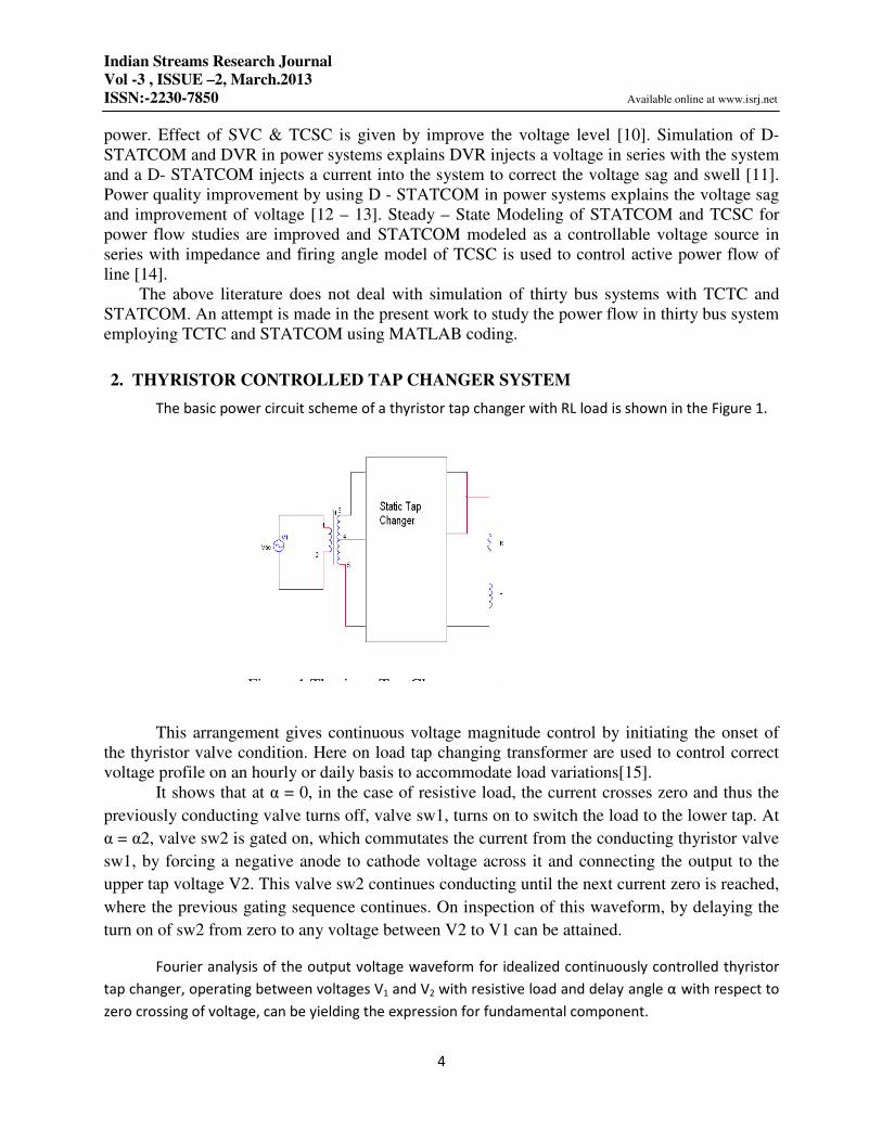
2. THYRISTOR CONTROLLED TAP CHANGER SYSTEM
The basic power circuit scheme of a thyristor tap changer with RL load is shown in the Figure 1.
This arrangement gives continuous voltage magnitude control by initiating the onset of
the thyristor valve condition. Here on load tap changing transformer are used to control correct
voltage profile on an hourly or daily basis to accommodate load variations[15].
It shows that at α = 0, in the case of resistive load, the current crosses zero and thus the
previously conducting valve turns off, valve sw1, turns on to switch the load to the lower tap. At
α = α2, valve sw2 is gated on, which commutates the current from the conducting thyristor valve
sw1, by forcing a negative anode to cathode voltage across it and connecting the output to the
upper tap voltage V2. This valve sw2 continues conducting until the next current zero is reached,
where the previous gating sequence continues. On inspection of this waveform, by delaying the
turn on of sw2 from zero to any voltage between V2 to V1 can be attained.
Fourier analysis of the output voltage waveform for idealized continuously controlled thyristor
tap changer, operating between voltages V1 and V2 with resistive load and delay angle α with respect to
zero crossing of voltage, can be yielding the expression for fundamental component.
Figure 1 Thyristor Tap Changer system

Indian Streams Research Journal
Vol -3 , ISSUE –2, March.2013
ISSN:-2230-7850 Available online at www.isrj.net
5
(1)
(2)
Where
V = amplitude of the fundamental
Ψ = phase angle of the fundamental with respect to unregulated voltage.
a1 = (V2 –V1/ 2 π) (cos2 α -1)
b1 = V1 + (V2 +V1/ π) (π -α + sin2 α /2 π)
The variation of amplitude V and Ψ of the fundamental voltage V with delay angle α for an assumed
± 10% regulation range (V1 = 0.9 and V2 = 1.1 on)
3. STATCOM
3.1 Emerging FACTS controller
One of the many devices under the FACTS family, a STATCOM is a regulating device which can be
used to regulate the flow of reactive power in the system independent of other system parameters.
STATCOM has no long term energy support on the dc side and it cannot exchange real power with the ac
system.
STATCOM is a shunt connected reactive power compensation device. It is capable of generating &
absorbing the reactive power. It can be improve the power system in the areas are
• Dynamic voltage control in transmission and distribution.
• Power oscillation damping in transmission system
• Transient stability.
• Voltage flicker control
• Control not only reactive power but also active power in the connected lines.
3.2 Principle of operation
V =√a12 +b1
2
Ψ = tan -1
(a 1 / b 1)
Indian Streams Research Journal
Vol -3 , ISSUE –2, March.2013
ISSN:-2230-7850 Available online at www.isrj.net
6
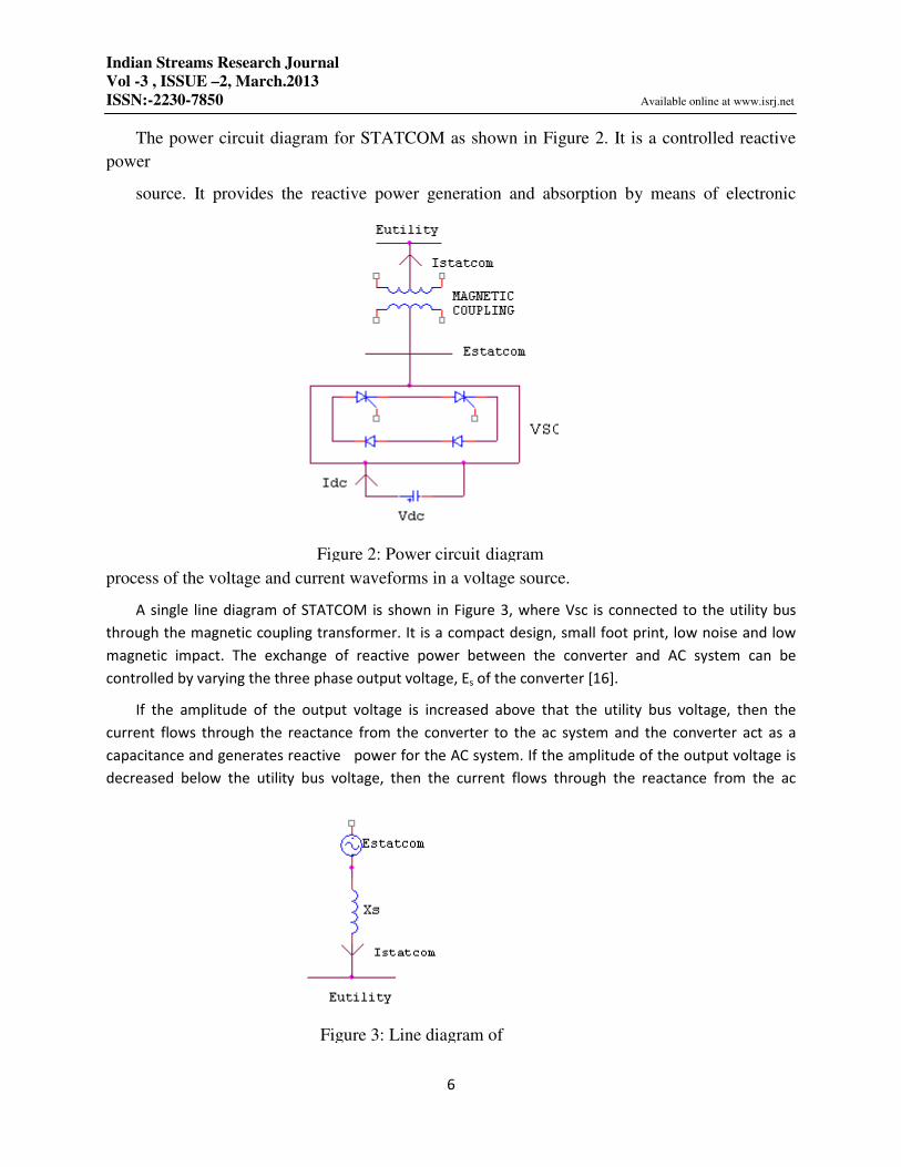
The power circuit diagram for STATCOM as shown in Figure 2. It is a controlled reactive
power
source. It provides the reactive power generation and absorption by means of electronic
process of the voltage and current waveforms in a voltage source.
A single line diagram of STATCOM is shown in Figure 3, where Vsc is connected to the utility bus
through the magnetic coupling transformer. It is a compact design, small foot print, low noise and low
magnetic impact. The exchange of reactive power between the converter and AC system can be
controlled by varying the three phase output voltage, Es of the converter [16].
If the amplitude of the output voltage is increased above that the utility bus voltage, then the
current flows through the reactance from the converter to the ac system and the converter act as a
capacitance and generates reactive power for the AC system. If the amplitude of the output voltage is
decreased below the utility bus voltage, then the current flows through the reactance from the ac
Figure 2: Power circuit diagram
Figure 3: Line diagram of

Indian Streams Research Journal
Vol -3 , ISSUE –2, March.2013
ISSN:-2230-7850 Available online at www.isrj.net
7
system to the converter and the converter act as inductance and it absorbs the reactive power for the ac
system.
If the output voltage equals the AC system, then the reactive power exchange becomes zero. In that
condition, STATCOM is said to be in a floating state. STATCOM controller provides voltage support by
generating or absorbing reactive power at the point of common coupling without the need of large
external reactors or capacitor banks. STATCOM controller provides voltage support by generating or
absorbing reactive power at the point of common coupling without the need of large external reactors
or capacitor banks.
4. POWER FLOW CONTROL
The power transmission line can be represented by a two bus system “K” and “m” in ordinary
form [17]. Basically load flow problem involves solving the non – linear algebraic equations which
represent the network under steady state conditions. The injected active and reactive power at bus – k
is
Pk = Gkk Vk2 (Gkm cos∂km + Bkm sin∂km) Vk Vm (3)
Qk = - Bkk Vk2 (Gkm sin∂km - Bkm cos∂km ) Vk Vm (4)
Pk= Gmm Vm2 (Gmk cos∂mk + Bmk sin∂mk) Vk Vm (5)
Qk= - Bmm Vk2 (Gmk sin∂mk - Bmk cos∂mk ) Vk Vm (6)
The nodal power flow equations are
P = f (V, θ, G, B) (7)
(8)
4.1 Newton – Raphson power flow
In large scale power flow studies, the newton Raphson has provided most successful owing
to its strong convergence characteristics [18]. The power flow Newton – Raphson algorithm is
expressed by the following equation
Q = g (V, θ, G, B)

Indian Streams Research Journal
Vol -3 , ISSUE –2, March.2013
ISSN:-2230-7850 Available online at www.isrj.net
8
∆�∆� = ���/�� � ��/�� ��/� � ��/�� ∆∆�/� (9)
Where ∆p and ∆Q are bus active and reactive power, while θ and v are bus magnitude and
angle respectively
4.2 Modeling of power system with STATCOM
It is acceptable to except that for the aim of positive sequence power flow analysis the
STATCOM will be represented by a synchronous voltage source with maximum and minimum
voltage magnitude limits [19]. The synchronous voltage source stands for the fundamental
Fourier series component of the switched voltage waveform at the AC converter terminal of the
STATCOM. The bus at which the STATCOM is connected to a PV bus, which may change to a
PQ bus in the case of limits are being violated. In this case, the generated or observed reactive
power would reach to the maximum limit. The equivalent circuit diagram of STATCOM shown
in the below figure 4 is used to obtain the mathematical model of the controller for power flow
algorithms .
Figure 4 : equivalent circuit diagram of STATCOM
The power flow equations for the STATCOM are given below
Evr= Vvr (cos�vr +j sin � vr) (10)
Based on the shunt connection shown in the figure 1, the following equation may be written
as
Svr = Vvr I*vr = Vvr Y
*vr (V
*vr - V
*k) (11)
After performing some complex operations, the following active and reactive power
equations are obtained for the converter and bus K, respectively.
Pvr = V2
vr Gvr + Vvr Vk ( Gvr cos (� vr – θ k) + Bvr sin (� vr – θ k) ) (12)
Qvr = - V2
vr Bvr + Vvr Vk ( Gvr sin (� vr – θ k) + Bvr cos (� vr – θ k) ) (13)
Ik
IvR
VkLθk ZvR VvRLθvR
Indian Streams Research Journal
Vol -3 , ISSUE –2, March.2013
ISSN:-2230-7850 Available online at www.isrj.net
9
Pk = V2k Gvr + Vk Vvr ( Gvr cos (θ k – � vr) + Bvr sin (θ k – � vr) ) (14)
Qk = - V2
k Bvr + Vk Vvr ( Gvr sin (θ k – � vr) + Bvr cos (θ k – � vr) ) (15)
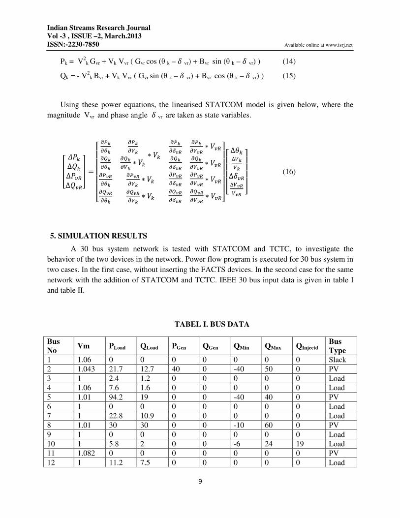
Using these power equations, the linearised STATCOM model is given below, where the
magnitude Vvr and phase angle � vr are taken as state variables.
� ��∆��∆���∆���� =
������� ������������
������������ ∗ �� ∗ ������� ! ����� ! ∗ �������� ! ����� ! ∗ ����� !���
�� !��� ∗ �� �� !�� ! �� !�� ! ∗ ����� !����� !��� ∗ �� �� !�� ! �� !�� ! ∗ ���"#
####$
������
∆�∆����∆���∆� !� ! "####$ (16)
5. SIMULATION RESULTS
A 30 bus system network is tested with STATCOM and TCTC, to investigate the
behavior of the two devices in the network. Power flow program is executed for 30 bus system in
two cases. In the first case, without inserting the FACTS devices. In the second case for the same
network with the addition of STATCOM and TCTC. IEEE 30 bus input data is given in table I
and table II.
TABEL I. BUS DATA
Bus
No Vm PLoad QLoad PGen QGen QMin QMax QInjectd
Bus
Type
1 1.06 0 0 0 0 0 0 0 Slack
2 1.043 21.7 12.7 40 0 -40 50 0 PV
3 1 2.4 1.2 0 0 0 0 0 Load
4 1.06 7.6 1.6 0 0 0 0 0 Load
5 1.01 94.2 19 0 0 -40 40 0 PV
6 1 0 0 0 0 0 0 0 Load
7 1 22.8 10.9 0 0 0 0 0 Load
8 1.01 30 30 0 0 -10 60 0 PV
9 1 0 0 0 0 0 0 0 Load
10 1 5.8 2 0 0 -6 24 19 Load
11 1.082 0 0 0 0 0 0 0 PV
12 1 11.2 7.5 0 0 0 0 0 Load

Indian Streams Research Journal
Vol -3 , ISSUE –2, March.2013
ISSN:-2230-7850 Available online at www.isrj.net
10
13 1.071 0 0 0 0 -6 24 0 PV
14 1 6.2 1.6 0 0 0 0 0 Load
15 1 8.2 2.5 0 0 0 0 0 Load
16 1 3.5 1.8 0 0 0 0 0 Load
17 1 9 5.8 0 0 0 0 0 Load
18 1 3.2 0.9 0 0 0 0 0 Load
19 1 9.5 3.4 0 0 0 0 0 Load
20 1 2.2 0.7 0 0 0 0 0 Load
21 1 17.5 11.2 0 0 0 0 0 Load
22 1 0 0 0 0 0 0 0 Load
23 1 3.2 1.6 0 0 0 0 0 Load
24 1 8.7 6.7 0 0 0 0 4.3 Load
25 1 0 0 0 0 0 0 0 Load
26 1 3.5 2.3 0 0 0 0 0 Load
27 1 0 0 0 0 0 0 0 Load
28 1 0 0 0 0 0 0 0 Load
29 1 2.4 0.9 0 0 0 0 0 Load
30 1 10.6 1.9 0 0 0 0 0 Load
TABEL II. LINE DATA
From Bus To Bus R (pu) X (pu) ½ B (pu) Line / Trans.
Tap Position
1 2 0.0192 0.0575 0.0264 Line
1 3 0.0452 0.1852 0.0204 Line
2 4 0.057 0.1737 0.0184 Line
3 4 0.0132 0.0379 0.0042 Line
2 5 0.0472 0.1983 0.0209 Line
2 6 0.0581 0.1763 0.0187 Line
4 6 0.0119 0.0414 0.0045 Line
5 7 0.046 0.116 0.0102 Line
6 7 0.0267 0.082 0.0085 Line
6 8 0.012 0.042 0.0045 Line
6 9 0 0.208 0 0.978
6 10 0 0.556 0 0.969
9 11 0 0.208 0 Line
9 10 0 0.11 0 Line
4 12 0 0.256 0 0.932
12 13 0 0.14 0 Line
12 14 0.1231 0.2559 0 Line
12 15 0.0662 0.1304 0 Line
12 16 0.0945 0.1987 0 Line
14 15 0.221 0.1997 0 Line
16 17 0.0824 0.1923 0 Line
Indian Streams Research Journal
Vol -3 , ISSUE –2, March.2013
ISSN:-2230-7850 Available online at www.isrj.net
11
15 18 0.1073 0.2185 0 Line
18 19 0.0639 0.1292 0 Line
19 20 0.034 0.068 0 Line
10 20 0.0936 0.209 0 Line
10 17 0.0324 0.0845 0 Line
10 21 0.0348 0.0749 0 Line
10 22 0.0727 0.1499 0 Line
21 22 0.0116 0.0236 0 Line
15 23 0.1 0.202 0 Line
22 24 0.115 0.179 0 Line
23 24 0.132 0.27 0 Line
24 25 0.1885 0.3292 0 Line
25 26 0.2544 0.38 0 Line
25 27 0.1093 0.2087 0 Line
28 27 0 0.396 0 0.968
27 29 0.2198 0.4153 0 Line
27 30 0.3202 0.6027 0 Line
29 30 0.2399 0.4533 0 Line
8 28 0.0636 0.2 0.0214 Line
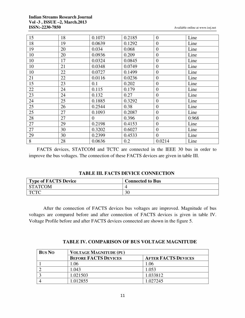
FACTS devices, STATCOM and TCTC are connected in the IEEE 30 bus in order to
improve the bus voltages. The connection of these FACTS devices are given in table III.
TABLE III. FACTS DEVICE CONNECTION
Type of FACTS Device Connected to Bus
STATCOM 4
TCTC 30
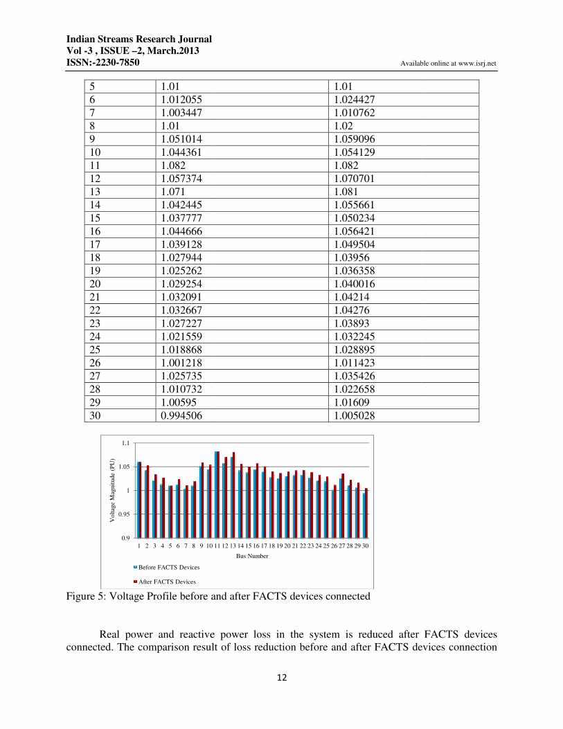
After the connection of FACTS devices bus voltages are improved. Magnitude of bus
voltages are compared before and after connection of FACTS devices is given in table IV.
Voltage Profile before and after FACTS devices connected are shown in the figure 5.
TABLE IV. COMPARISON OF BUS VOLTAGE MAGNITUDE
BUS NO VOLTAGE MAGNITUDE (PU)
BEFORE FACTS DEVICES AFTER FACTS DEVICES
1 1.06 1.06
2 1.043 1.053
3 1.021503 1.033812
4 1.012855 1.027245
Indian Streams Research Journal
Vol -3 , ISSUE –2, March.2013
ISSN:-2230-7850
5 1.01
6 1.012055
7 1.003447
8 1.01
9 1.051014
10 1.044361
11 1.082
12 1.057374
13 1.071
14 1.042445
15 1.037777
16 1.044666
17 1.039128
18 1.027944
19 1.025262
20 1.029254
21 1.032091
22 1.032667
23 1.027227
24 1.021559
25 1.018868
26 1.001218
27 1.025735
28 1.010732
29 1.00595
30 0.994506
Figure 5: Voltage Profile before
Real power and reactive power loss in the system is reduced after FACTS devices
connected. The comparison result of loss reduction before and after FACTS devices connection
0.9
0.95
1
1.05
1.1
1 2 3 4 5 6 7 8 9 10
Volt
age
Mag
nit
ud
e (P
U)
Before FACTS Devices
After FACTS Devices
Indian Streams Research Journal
Available online at www.isrj.net
12
1.01
1.024427
1.010762
1.02
1.059096
1.054129
1.082
1.070701
1.081
1.055661
1.050234
1.056421
1.049504
1.03956
1.036358
1.040016
1.04214
1.04276
1.03893
1.032245
1.028895
1.011423
1.035426
1.022658
1.01609
1.005028
: Voltage Profile before and after FACTS devices connected
Real power and reactive power loss in the system is reduced after FACTS devices
connected. The comparison result of loss reduction before and after FACTS devices connection
10 11 12 13 14 15 16 17 18 19 20 21 22 23 24 25 26 27 28 29 30
Bus Number
Available online at www.isrj.net
Real power and reactive power loss in the system is reduced after FACTS devices
connected. The comparison result of loss reduction before and after FACTS devices connection
Indian Streams Research Journal
Vol -3 , ISSUE –2, March.2013
ISSN:-2230-7850
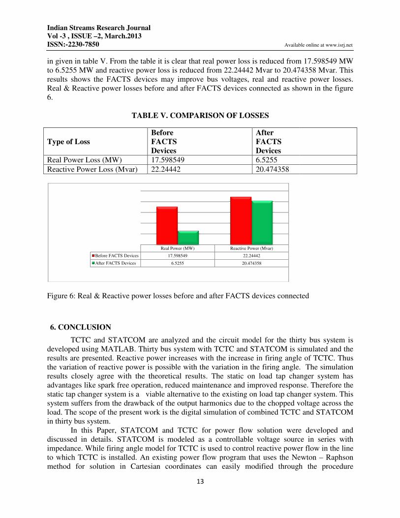
in given in table V. From the table it is clear
to 6.5255 MW and reactive power loss is reduced from 22.24442 Mvar to 20.474358 Mvar. This
results shows the FACTS devices may improve bus voltages, real and reactive power losses.
Real & Reactive power losses before and after FACTS devices connected
6.
TABLE V. COMPARISON OF LOSSES
Type of Loss
Real Power Loss (MW)
Reactive Power Loss (Mvar)
Figure 6: Real & Reactive power losses before and after FACTS devices connected
6. CONCLUSION
TCTC and STATCOM are analyzed and the circuit model for the
developed using MATLAB. Thirty
results are presented. Reactive power increases with the increase in firing angle of TCTC. Thus
the variation of reactive power is possible with the variation in the firing angle. The simulation
results closely agree with the theoretical results. The static on load tap changer system has
advantages like spark free operation, reduced maintenance and improved response.
static tap changer system is a viable alternative to the existing on l
system suffers from the drawback of the output harmonics due to the chopped voltage across the
load. The scope of the present work is the digital simulation of combined TCTC and STATCOM
in thirty bus system.
In this Paper, STATCOM and TCTC for power flow solution were developed and
discussed in details. STATCOM is modeled as a controllable voltage source in series with
impedance. While firing angle model for TCTC is used to control reactive power flow in the line
to which TCTC is installed. An existing power flow program that uses the Newton
method for solution in Cartesian coordinates can easily modified through the procedure
Before FACTS Devices
After FACTS Devices
Indian Streams Research Journal
Available online at www.isrj.net
13
in given in table V. From the table it is clear that real power loss is reduced from 17.598549 MW
to 6.5255 MW and reactive power loss is reduced from 22.24442 Mvar to 20.474358 Mvar. This
results shows the FACTS devices may improve bus voltages, real and reactive power losses.
sses before and after FACTS devices connected as shown in the figure
TABLE V. COMPARISON OF LOSSES
Before
FACTS
Devices
After
FACTS
Devices
17.598549 6.5255
22.24442 20.474358
: Real & Reactive power losses before and after FACTS devices connected
TCTC and STATCOM are analyzed and the circuit model for the thirty
Thirty bus system with TCTC and STATCOM is simulated and the
results are presented. Reactive power increases with the increase in firing angle of TCTC. Thus
the variation of reactive power is possible with the variation in the firing angle. The simulation
ts closely agree with the theoretical results. The static on load tap changer system has
advantages like spark free operation, reduced maintenance and improved response.
static tap changer system is a viable alternative to the existing on load tap changer system. This
system suffers from the drawback of the output harmonics due to the chopped voltage across the
load. The scope of the present work is the digital simulation of combined TCTC and STATCOM
COM and TCTC for power flow solution were developed and
discussed in details. STATCOM is modeled as a controllable voltage source in series with
impedance. While firing angle model for TCTC is used to control reactive power flow in the line
An existing power flow program that uses the Newton
method for solution in Cartesian coordinates can easily modified through the procedure
Real Power (MW) Reactive Power (Mvar)
17.598549 22.24442
6.5255 20.474358
Available online at www.isrj.net
that real power loss is reduced from 17.598549 MW
to 6.5255 MW and reactive power loss is reduced from 22.24442 Mvar to 20.474358 Mvar. This
results shows the FACTS devices may improve bus voltages, real and reactive power losses.
as shown in the figure
: Real & Reactive power losses before and after FACTS devices connected
thirty bus system is
bus system with TCTC and STATCOM is simulated and the
results are presented. Reactive power increases with the increase in firing angle of TCTC. Thus
the variation of reactive power is possible with the variation in the firing angle. The simulation
ts closely agree with the theoretical results. The static on load tap changer system has
advantages like spark free operation, reduced maintenance and improved response. Therefore the
oad tap changer system. This
system suffers from the drawback of the output harmonics due to the chopped voltage across the
load. The scope of the present work is the digital simulation of combined TCTC and STATCOM
COM and TCTC for power flow solution were developed and
discussed in details. STATCOM is modeled as a controllable voltage source in series with
impedance. While firing angle model for TCTC is used to control reactive power flow in the line
An existing power flow program that uses the Newton – Raphson
method for solution in Cartesian coordinates can easily modified through the procedure
Indian Streams Research Journal
Vol -3 , ISSUE –2, March.2013
ISSN:-2230-7850 Available online at www.isrj.net
14
presented in this paper. This procedure was applied on the thirty bus power system and
implemented by suing the MATLAB software package. The results obtained show the
effectiveness and robustness of the proposed models.
REFERENCES
[1] G.Hingorani (2003), “FACTS” IEEE spectrum, vol30, pp40-45.
[2] C.Benachaiba and B.Ferdi (2009), “Power quality improvement using DVR”, American
Journal of Applied sciences, pp 396 – 400.
[3] M.R.Iravani, Paul.L Dandeno and D.Maratukulam, “application of static phase shifter in
power system”, IEEE trans.power delivers, vol 9 pp1600 – 1608.
[4] Alireza Seifi, Sasan Cholami m.s and Amin Shabanpour (2010), “Power flow study amd
comparisoin of FACTS: Series (SSSC), Shunt (STATCOM) and Shunt – Series (UPFC)”, The
pacific Journal of Science and Technology, Volume 11, No 1, pp 129 – 137.
[5] Hingorani N.G (2001), understanding FACTS concepts IEEE proc. Standard Publishing
[6] Zhang X.P, C.Rehtanz and B.Pal (2006), “Understanding FACTS: concepts and Technology
of FACTS,Wiley – IEEE press: Newyork, ISBN 0-7803-3464-7.
[7] Noroozan. M and G. Anderson (1993), Power flow control by use of controllable series
components, IEEE Trans. Power delivery, 8 1420 -1429.
[8] Deepika Masand, Shailandra Jain and ayatri Agnihotri (2008),”Control Strategies for
Distribution Static Compensator for Power Quality improvement”, IEEE Journal of research
vol.54, Issue 6.
[9] S.D. SundarSingh Jebaseelan and Dr. R. Raja Prabu (2012), “Modelling and Simulation of
Thirty Bus System Using Multiple STATCOM & TCTC”, European Journal of scientific
Research, ISSN 1450-216X Vol.81 No.2 (2012), pp.285-297.
[10] S.V.Ravi kumar and S.Siva nagaraju (2007), “Simulation of D- STATCOM and DVR in
power systems,” ARPN Journal of Engineering and Applied Sciences, Vol 2, No 3.
[11] S.D. SundarSingh Jebaseelan and Dr. R. Raja Prabu (2011), “Digital Simulation of Eight
Bus System using TCTC & STATCOM”, International Journal on Intelligent Electronic systems,
Sathyabama University, Vol 5, No 2, pp 52 – 58.
[12] S.D. SundarSingh Jebaseelan and Dr. R. Raja Prabu (2011), “Digital Simulation of Thirty
Bus System using TCTC & STATCOM”, Ciit International Journal of Programmable Device
Circuits and Systems, Vol 3, No 12, pp 675 – 680.

Indian Streams Research Journal
Vol -3 , ISSUE –2, March.2013
ISSN:-2230-7850 Available online at www.isrj.net
15
[13] Pierre Gipoux, Gilbert sybille and Hoang Le-Huy (2001),“Modeling and simulation of a
distribution STATCOM using simulink’s power system block”, conference of the IEEE
Industrial Electronics society.
[14]M.O.HASSAN,S.J. CHENG AND Z.A.ZAKARIA (2009), “ Steady state modeling of static
Synchronous compensator and Thyristor controlled series compensator for power flow analysis”,
Information technology Journal.
[15] S.D. Sundarsingh Jebaseelan and Dr. R. Raja Prabu, “Digital Simulation of Thyristor
Controlled Tap changer System Using Simulink”, National conference on Future Challenges and
Budding Intelligent Techniques in Electrical and Electronics Engineering, 29th & 30th July
2010, Sathyabama University, pp. 55 – 58.
[16] S.D. Sundarsingh Jebaseelan and Dr. R. Raja Prabu, “Analysis and Implementation of Eight
Bus System Using STATCOM”, National conference on Computational Intelligence Power
Apparatus and Systems, CIPS 2012, 18th - 20th April 2012, SRM University,pp.181 – 184.
[17] 2. S.D. Sundarsingh Jebaseelan and Dr. R. Raja Prabu, “Simulation and Implementation of
Thirty Bus System Using TCTC”, National conference on Trends in Electronics,
Instrumentation, Embedded Systems and Automation, TRENDS 12, 30th & 31stMarch 2012,
Karunya University, pp. 28 – 32.
[18] Gotham D.J and G.T.Heydt (1998), “Power flow control and Power flow studies for systems
with FACTS devices”, IEEE Trans.Power system13(1), pp 60 – 66
[19] Zhang X.P, C.Rehtanz and B.Pal (2006), “FACTS: Modelling and control”,Wiley Springer
Verlag: Berlin, Germany.
[20] Adlin Sughi .M.G, Siji .A and S.D.Sundarsingh Jebaseelan, “Simulation and
Implementation of STATCOM using Multi level Inverter”, National Conference on Recent
advancements in power control & Drives, RAPCD – 11, Eienstien Engineering College, 25th and
26th March 2011, pp.14 – 17.
S.D.Sundarsingh Jebaseelan was born in 1979 and he received his B.E in Electrical and Electronics
Engineering degree from Bharathiyar University in the year 2002. He obtained his M.E degree in Power
systems from Annamalai University in the year 2005. Presently he is a research scholar at Sathyabama
University. He is working in the Area of Reactive power compensation.
R.Raja Prabu was born in 1967. He received B.E. and M.E. in degrees in electrical engineering and power
system engineering in 1988 and 1990 respectively from Annamalai University, Chidambaram, India. He
received Ph.D. degree in high voltage engineering from College of Engineering, Guindy, Anna University,
Chennai, India. Currently he is working as professor and head in the department of electrical and
electronics engineering, B.S.Abdur Rahman University, Chennai, India. He is a Member of IEEE, CIGRE
and I.S.T.E. His research area includes outdoor insulation, digital protection, high voltage application in
life science, power quality and Nano-dielectrics. He has got more than 25 research publications to his credit
Related Documents