. RCC RTEMS-5 Cross Compiler (RCC) 2020 User's Manual The most important thing we build is trust RCC User's Manual RCC-UM 1 www.cobham.com/gaisler May 2020, Version 1.3-rc8

Welcome message from author
This document is posted to help you gain knowledge. Please leave a comment to let me know what you think about it! Share it to your friends and learn new things together.
Transcript
.
RCC
RTEMS-5 Cross Compiler (RCC)
2020 User's Manual
The most important thing we build is trust
RCC User's Manual
RCC-UM 1 www.cobham.com/gaislerMay 2020, Version 1.3-rc8
RCC-UMMay 2020, Version 1.3-rc8
2 www.cobham.com/gaisler
Table of Contents1. Introduction ............................................................................................................................. 7
1.1. General ......................................................................................................................... 71.2. Installation on host platform ............................................................................................. 7
1.2.1. Host requirements ................................................................................................ 71.2.2. Installing RCC on Windows platforms ..................................................................... 81.2.3. Installing on Linux platform .................................................................................. 9
1.3. Contents of /opt/rcc-1.3-rc8 ............................................................................................ 101.4. RCC tools ................................................................................................................... 101.5. Documentation ............................................................................................................. 111.6. RCC source Git access .................................................................................................. 121.7. Changes since RCC-1.2 ................................................................................................. 121.8. Known limitations in the release candidate ........................................................................ 131.9. Support ....................................................................................................................... 13
2. Using RCC ............................................................................................................................ 142.1. General development flow .............................................................................................. 142.2. Compiler toolchain ....................................................................................................... 14
2.2.1. sparc-gaisler-rtems5 toolchain BSP selection ........................................................... 142.2.2. Common compiler options ................................................................................... 152.2.3. GNU GCC toolchain .......................................................................................... 152.2.4. LLVM Clang toolchain ....................................................................................... 162.2.5. Floating-point considerations ................................................................................ 182.2.6. SPARC V8 instructions ....................................................................................... 182.2.7. LEON CASA instruction ..................................................................................... 182.2.8. LEON UMAC/SMAC instructions ........................................................................ 182.2.9. LEON3/4 CPU counter ....................................................................................... 182.2.10. Enabling/Disabling Interrupt by use of Write Partial PSR instruction .......................... 19
2.3. RTEMS applications ..................................................................................................... 192.4. Memory organisation ..................................................................................................... 192.5. Board-support packages (BSPs) ....................................................................................... 20
2.5.1. LEON3 BSP ..................................................................................................... 202.5.2. GR740 BSP ...................................................................................................... 202.5.3. GR712RC BSP .................................................................................................. 222.5.4. UT699 BSP ....................................................................................................... 222.5.5. UT699E/UT700 BSP .......................................................................................... 222.5.6. AT697F BSP ..................................................................................................... 22
2.6. Driver Manager ............................................................................................................ 232.6.1. Initialization ...................................................................................................... 232.6.2. Configuration .................................................................................................... 232.6.3. Driver configuration ........................................................................................... 242.6.4. drvmgr command ............................................................................................... 25
2.7. Network configuration ................................................................................................... 272.8. PCI ............................................................................................................................ 272.9. LEON3 BSP multiprocessing configurations ...................................................................... 27
2.9.1. Memory and device resource sharing ..................................................................... 282.9.2. Interrupt considerations ....................................................................................... 282.9.3. Symmetric multiprocessing (SMP) configuration ...................................................... 282.9.4. Asymmetric multiprocessing (AMP) configuration ................................................... 292.9.5. RTEMS SMP AMP example ................................................................................ 31
2.10. Making boot-proms ..................................................................................................... 313. Examples ............................................................................................................................... 32
3.1. Overview .................................................................................................................... 323.2. Building ...................................................................................................................... 32
4. Execution and debugging ......................................................................................................... 334.1. TSIM .......................................................................................................................... 334.2. GRMON ..................................................................................................................... 33
RCC-UMMay 2020, Version 1.3-rc8
3 www.cobham.com/gaisler
4.3. GDB with GRMON and TSIM ....................................................................................... 344.4. Using DDD graphical front-end to gdb ............................................................................. 35
I. Device drivers reference ........................................................................................................... 365. GRLIB AMBA Plug&Play bus .......................................................................................... 37
5.1. Introduction ......................................................................................................... 375.2. Overview ............................................................................................................ 385.3. Initialization ......................................................................................................... 385.4. Finding AMBAPP devices by Plug&Play .................................................................. 385.5. Allocating a device structure .................................................................................. 395.6. Name database ..................................................................................................... 395.7. Frequency of a device ........................................................................................... 39
6. Driver Manager .............................................................................................................. 406.1. Introduction ......................................................................................................... 406.2. Overview ............................................................................................................ 406.3. Configuration ....................................................................................................... 456.4. Initialization ......................................................................................................... 476.5. Interrupt .............................................................................................................. 476.6. Address translation ............................................................................................... 486.7. Function Interface ................................................................................................. 49
7. RMAP Stack .................................................................................................................. 507.1. Introduction ......................................................................................................... 507.2. Driver Interface .................................................................................................... 507.3. Logical and Path addressing ................................................................................... 507.4. Zero-copy implementation ...................................................................................... 507.5. RMAP GRSPW driver ........................................................................................... 507.6. Thread-safe .......................................................................................................... 517.7. User interface ...................................................................................................... 51
8. SpaceWire Network model ............................................................................................... 548.1. Introduction ......................................................................................................... 548.2. Overview ............................................................................................................ 548.3. Requirements ....................................................................................................... 548.4. Node Description .................................................................................................. 548.5. Read and write operation ....................................................................................... 548.6. Interrupt handling ................................................................................................. 558.7. Using the spacewire bus driver ............................................................................... 55
9. AMBA over SpaceWire ................................................................................................... 569.1. Introduction ......................................................................................................... 569.2. Overview ............................................................................................................ 569.3. Requirements ....................................................................................................... 569.4. Interrupt handling ................................................................................................. 569.5. Memory allocation on target ................................................................................... 569.6. Differences between on-chip AMBA drivers .............................................................. 56
10. LEON PCI host bridge drivers ......................................................................................... 5810.1. Introduction ....................................................................................................... 5810.2. Sources ............................................................................................................. 5810.3. Configuration ..................................................................................................... 5810.4. User interface ..................................................................................................... 59
11. GRPCI2 DMA driver ..................................................................................................... 6111.1. Introduction ....................................................................................................... 6111.2. Software design overview ..................................................................................... 6111.3. DMA user interface ............................................................................................. 6311.4. API reference ..................................................................................................... 69
12. GR-RASTA-ADCDAC PCI peripheral .............................................................................. 7113. GR-RASTA-IO PCI peripheral ........................................................................................ 7214. GR-RASTA-TMTC PCI peripheral ................................................................................... 7315. GR-RASTA-SPW_ROUTER PCI Peripheral ...................................................................... 7416. GR-CPCI-LEON4-N2X PCI Peripheral ............................................................................. 75
16.1. Driver registration ............................................................................................... 75
RCC-UMMay 2020, Version 1.3-rc8
4 www.cobham.com/gaisler
16.2. Driver resource configuration ................................................................................ 7517. GR-CPCI-GR740 PCI Peripheral ...................................................................................... 76
17.1. Driver registration ............................................................................................... 7617.2. Driver resource configuration ................................................................................ 76
18. GRSPW Packet driver .................................................................................................... 7718.1. Introduction ....................................................................................................... 7718.2. Software design overview ..................................................................................... 7818.3. Device Interface .................................................................................................. 8518.4. DMA interface ................................................................................................... 9518.5. API reference ................................................................................................... 111
19. GRSPW GRLIB SpaceWire driver .................................................................................. 11419.1. Introduction ...................................................................................................... 11419.2. User interface ................................................................................................... 11419.3. Receiver example .............................................................................................. 124
20. GRSPW ROUTER driver .............................................................................................. 12520.1. Introduction ...................................................................................................... 12520.2. Software design overview ................................................................................... 12520.3. GRSPW ROUTER user interface ......................................................................... 12620.4. API reference ................................................................................................... 147
21. SPWTDP driver .......................................................................................................... 15021.1. Introduction ...................................................................................................... 15021.2. Software design overview ................................................................................... 15021.3. SPWTDP user interface ...................................................................................... 15121.4. API reference ................................................................................................... 161
22. GR1553B GRLIB MIL-STD-1553B driver ....................................................................... 16322.1. Introduction ...................................................................................................... 16322.2. GR1553B Hardware ........................................................................................... 16322.3. Software driver ................................................................................................. 16322.4. Driver Registration ............................................................................................ 16322.5. Examples ......................................................................................................... 163
23. GR1553B remote terminal driver .................................................................................... 16423.1. Introduction ...................................................................................................... 16423.2. User Interface ................................................................................................... 164
24. GR1553B bus monitor driver ......................................................................................... 17424.1. Introduction ...................................................................................................... 17424.2. User Interface ................................................................................................... 174
25. GR1553B bus controller driver ....................................................................................... 17925.1. Introduction ...................................................................................................... 17925.2. BC Device Handling .......................................................................................... 18025.3. Descriptor List Handling .................................................................................... 182
26. B1553BRM GRLIB Actel Core1553BRM driver ............................................................... 19426.1. Introduction ...................................................................................................... 19426.2. User Intrerface .................................................................................................. 194
27. B1553RT GRLIB Actel Core1553 RT driver .................................................................... 20327.1. Introduction ...................................................................................................... 20327.2. User interface ................................................................................................... 203
28. GRCAN CAN driver .................................................................................................... 20828.1. Introduction ...................................................................................................... 20828.2. User Interface ................................................................................................... 208
29. CAN_OC GRLIB Opencores CAN driver ........................................................................ 21729.1. Introduction ...................................................................................................... 21729.2. User interface ................................................................................................... 217
30. SatCAN driver (SatCAN) .............................................................................................. 22430.1. Introduction ...................................................................................................... 22430.2. User interface ................................................................................................... 224
31. CAN_MUX driver (CAN_MUX) .................................................................................... 23231.1. Introduction ...................................................................................................... 23231.2. User interface ................................................................................................... 232

RCC-UMMay 2020, Version 1.3-rc8
5 www.cobham.com/gaisler
32. GRASCS driver ........................................................................................................... 23432.1. Introduction ...................................................................................................... 23432.2. User interface ................................................................................................... 23432.3. Examples code .................................................................................................. 237
33. APBUART console driver ............................................................................................. 23933.1. Introduction ...................................................................................................... 23933.2. User interface ................................................................................................... 239
34. SPICTRL GRLIB SPI master driver ................................................................................ 24234.1. Introduction ...................................................................................................... 24234.2. User interface ................................................................................................... 242
35. I2CMST GRLIB I2C Master driver ................................................................................. 24635.1. Introduction ...................................................................................................... 24635.2. User interface ................................................................................................... 246
36. GPIO Library .............................................................................................................. 24736.1. Introduction ...................................................................................................... 24736.2. Driver interface ................................................................................................. 24736.3. User interface ................................................................................................... 247
37. GRGPIO GRLIB GPIO driver ....................................................................................... 25037.1. Introduction ...................................................................................................... 25037.2. User interface ................................................................................................... 250
38. GRADCDAC GRLIB ADC/DAC driver .......................................................................... 25338.1. Introduction ...................................................................................................... 25338.2. User interface ................................................................................................... 253
39. GRTC GRLIB CCSDS Telecommand driver .................................................................... 26039.1. INTRODUCTION ............................................................................................. 26039.2. User interface ................................................................................................... 260
40. GRTM GRLIB CCSDS Telemetry Driver ........................................................................ 27140.1. Introduction ...................................................................................................... 27140.2. User interface ................................................................................................... 271
41. GRCTM driver ............................................................................................................ 28041.1. Introduction ...................................................................................................... 280
42. SPWCUC driver .......................................................................................................... 28342.1. Introduction ...................................................................................................... 28342.2. User interface ................................................................................................... 283
43. GRPWRX GRLIB PacketWire Receiver driver ................................................................. 28743.1. Introduction ...................................................................................................... 28743.2. User interface ................................................................................................... 287
44. GRAES GRLIB AES DMA driver .................................................................................. 29444.1. Introduction ...................................................................................................... 29444.2. User interface ................................................................................................... 294
45. AHB Status register driver ............................................................................................ 30145.1. Overview ......................................................................................................... 30145.2. Driver sources .................................................................................................. 30145.3. Driver registration ............................................................................................. 30145.4. Operation ......................................................................................................... 30145.5. User interface ................................................................................................... 301
46. L2CACHE driver ......................................................................................................... 30346.1. Introduction ...................................................................................................... 30346.2. Software design overview ................................................................................... 30346.3. L2CACHE user interface .................................................................................... 30446.4. API reference ................................................................................................... 316
47. GRIOMMU driver ....................................................................................................... 31847.1. Introduction ...................................................................................................... 31847.2. Software design overview ................................................................................... 31847.3. GRIOMMU user interface .................................................................................. 31947.4. API reference ................................................................................................... 329
48. L4STAT/L3STAT driver ............................................................................................... 33148.1. Introduction ...................................................................................................... 331
RCC-UMMay 2020, Version 1.3-rc8
6 www.cobham.com/gaisler
48.2. Software design overview ................................................................................... 33148.3. L4STAT user interface ....................................................................................... 33148.4. API reference ................................................................................................... 334
49. Memory Scrubber driver ............................................................................................... 33649.1. Introduction ...................................................................................................... 33649.2. Software design overview ................................................................................... 33649.3. Memory scrubber user interface ........................................................................... 33749.4. API reference ................................................................................................... 343
RCC-UMMay 2020, Version 1.3-rc8
7 www.cobham.com/gaisler
Chapter 1. Introduction
1.1. General
This document describes the RTEMS LEON/ERC32 GNU cross-compiler system (RCC). This chapter covers thefollowing topics:
• Overview• Installing RCC• Contents and directory structure of RCC• Compiling and linking LEON and ERC32 RTEMS applications• Debugging RTEMS application with GRMON, TSIM and GDB
RCC is a multi-platform development system based on the GNU family of freely available tools with additionaltools developed by RTEMS Community and Cobham Gaisler. RCC consists of the following packages:
• GCC-7.2.0 or LLVM/Clang-7.0.0 C/C++ compiler• GNU binary utilities 2.29• RTEMS-5.0 C/C++ real-time kernel, precompiled BSPs for LEON2/3/4 and ERC32• Newlib-2.5.0 (newlib-snapshot-20171222) standalone C-library• GDB-8.2.1 SPARC cross-debugger
RCC includes precompiled BSPs for LEON2/3/4 and ERC32 in different configurations and some examples toeasily get started using RTEMS on LEON/ERC32. The precompiled BSPs:
• UT699• UT700 (also used for UT699E)• GR712RC• GR712RC SMP configuration• GR740• GR740 SMP configuration• Generic LEON3• Generic LEON3 soft-float (floating point software emulation)• Generic LEON3 flat register window model• Generic LEON3 SMP configuration
NOTE: In the RCC-1.3 release candiadates the LEON2 and ERC32 are temporarily disabled but will be enabledin future releases.
1.2. Installation on host platform
1.2.1. Host requirements
RCC is provided for two host platforms: Linux/x86_64 and Windows/x86_64. The following are the platformsystem requirements:
Linux (GCC): Linux-2.6.x, glibc-2.11.1 (or higher)
Linux (LLVM): Linux-3.x, glibc-2.18 (or higher)
Windows (GCC/LLVM): MSYS base 2013.07.23 (or higher)
NOTE: Starting with RCC-1.3-rc7 release, precompiled SPARC objects/libraries are built with the DWARF4debugging format supported by GDB-8.2.1 and GRMON-3.1 and TSIM3. DWARF3 or later is not supportedby GDB-6.8, hence source level debugging is not supported for TSIM2 and GRMON2 unless the user rebuildsRTEMS kernel and Newlib with DWARF2 (-gdwarf-2 flag) updating the build scripts described in the followingsubsections.
In order to build samples and recompile the RTEMS kernel sources an MSYS environment and some specificdevelopment tools are required. MSYS provides standard UNIX tools such as make, find, autoconf, etc. and
RCC-UMMay 2020, Version 1.3-rc8
8 www.cobham.com/gaisler
MINGW provides GCC and BINUTILS built for Windows. The RTEMS-5 kernel source build system requiresspecific versions of automake-1.12.6 and autoconf-2.69 to work properly. The following links provides all toolsneccessary and section Section 1.2.2.1 describes the Windows MSYS setup flow briefly.
• http://www.mingw.org• http://sourceforge.net/projects/mingw/files/Installer/
• ftp://ftp.gnu.org/gnu/autoconf/• ftp://ftp.gnu.org/gnu/automake/
1.2.2. Installing RCC on Windows platforms
The toolchain installation zip file (sparc-rtems-5-gcc-7.2.0-1.3-rc8-mingw.zip) must be extract-ed to C:\opt creating the directory C:\opt\rcc-1.3-rc8. The toolchain executables can be invoked fromthe command prompt by adding the executable directory to the PATH environment variable. The directory C:\opt\rcc-1.3-rc8\bin can be added to the PATH variable by selecting "My Computer->Properties->Ad-vanced->Environment Variables". Development often requires some basic utilities such as make, but is not re-quired to compile. On Windows, the MSYS Base system can be installed to get a basic UNIX like developmentenvironment (including make).
The RTEMS build procedure rely on the autoconf and automake utilities to create Makefiles from the RTEMSsources. The MSYS Base system doesn't include the required version of autoconf and automake, instead they canbe compiled from sources as described below.
1.2.2.1. Installing MSYS
The MSYS package can be freely downloaded from http://www.mingw.org. It is available as an self extractinginstallation application (msys-get-installer.exe). The following text assumes the MSYS has been successfully in-stalled to C:\MINGW. The following tools, apart from the MSYS and MINGW base, are also required to be se-lected for installation from within the MSYS installer:
• msys-findutils• msys-m4• msys-perl
The directory where the toolchain is installed (C:\opt\rcc-1.3-rc8) must be found in /opt/rcc-1.3-rc8 from the MSYS environment, this can done by adding an mount entry similar to one of the examples belowto the /etc/fstab file in the MSYS environment.
C:/opt/rcc-1.3.x /opt/rcc-1.3.x
or
C:/opt /opt
The path to the toolchain binaries (C:\opt\rcc-1.3-rc8\bin) must added to the MSYS PATH environmentvariable. Below is an example of how to change the PATH variable in the MSYS shell.
export PATH=/opt/rcc-1.3.x/bin:$PATH
The toolchain installation can be tested by compiling the samples included in the toolchain,
$ cd /opt/rcc-1.3.x/src/samples $ make
1.2.2.2. Building Newlib from sources
RCC comes with the Newlib C library precompiled and its source code, thus this step is optional and in generalnot needed. The libraries can be found in sparc-gaisler-rtems5/lib/TARGET where TARGET is adirectory named according to the multilib path of a specific target, see Section 2.2.3.3.
The source code is located in src/newlib and required during source level debugging and when rebuildingnewlib. Newlib can be (re)built from sources using the src/build-newlib.sh script. By default it will buildNewlib once for every multilib defined for the compiler used. The libraries will overwrite the pre-built librariesthat comes with RCC. Additional target configurations can be added and or application specific compiler flagscan also be added to the script used when building newlib.
RCC-UMMay 2020, Version 1.3-rc8
9 www.cobham.com/gaisler
1.2.2.3. Installing RTEMS source
Installing the RTEMS kernel source code is optional but recommended when debugging applications. Thetoolchain libraries are built with debugging symbols making it possible for GDB to find the source files. The RCCRTEMS sources is assumed to be located in C:\opt\rcc-1.3-rc8\src\rcc-1.3-rc8. The RTEMSsources (rtems-5-1.3-rc8-src.txz) can be installed by extracting the source distribution to C:\opt\rcc-1.3-rc8\src creating the directory C:\opt\rcc-1.3-rc8\src\rcc-1.3-rc8.
Alternatively the sources can be obtained from the Git repository, see Section 1.6.
1.2.2.4. Building RTEMS from source
The RCC toolchain comes with pre-built RTEMS kernel for the most common LEON BSPs, thus this step isoptional.
The RTEMS build environment can be set up by following the Windows instructions available www.rtems.org[http://www.rtems.org] and are briefly described here. In addition to the environment installed in Section 1.2.2.1the RTEMS requires automake-1.12.6 and autoconf-2.69 to configure and build the RTEMS kernel. This sectiondescribes how to install autoconf, automake and building the RTEMS SPARC BSPS from source.
As previously mentioned the auto-tools can be downloaded from the GNU project's FTP. RCC comes with thetools and an install script found in the /opt/rcc-1.3-rc8/src/tools. The script is invoked from theMSYS shell:
$ cd /opt/rcc-1.3.x/src/tools $ sh autotools.sh $ exit
After installing automake and autoconf it may be required to restart the MSYS shell.
Once the tools has been installed and the MSYS shell has been restarted, the installed RTEMS sources can bebuilt manually or using the prepared Makefile available at /opt/rcc-1.3-rc8/src/build-rtems.sh.See Section 2.2 for details on how to set the compiler options used when building a BSP. The build process isdivided in four steps, in the first step the make scripts are generated this step is called bootstrap. The bootstrappingcan be done with the make target boot as the examples shows below. The bootstrap step is only needed to be rerunwhen adding or removing files from the source tree.
$ cd /opt/rcc-1.3.x/src/rcc-1.3.x $ ./bootstrap -c $ ./bootstrap -H $ ./boostrap
The second step configures the RTEMS kernel and a build environment in /opt/rcc-1.3-rc8/src/build,
$ cd /opt/rcc-1.3.x/src/build $ ../rcc-1.3.x/configure --target=sparc-gaisler-rtems5 --enable-rtemsbsp="BSPs" ..
The third and fourth steps compiles and installs the new kernel to /opt/rcc-1.3-rc8/sparc-gaisler-rtems5
$ make compile $ make install
1.2.3. Installing on Linux platform
The RCC directory tree is compiled to reside in the /opt/rcc-1.3-rc8 directory on all platforms. Afterobtaining the XZ compressed tarfile with the binary distribution, uncompress and untar it in a suitable location -if this is not /opt/rcc-1.3-rc8 then a link have to be created to point to the location of the RCC directory.The distribution can be installed with the following commands:
$ cd /opt $ tar -Jxf sparc-rtems-5-gcc-7.2.x-1.3.y-linux.txz
After the compiler is installed, add /opt/rcc-1.3-rc8/bin to the executables search path and /opt/rcc-1.3-rc8/man to the man path.
RCC-UMMay 2020, Version 1.3-rc8
10 www.cobham.com/gaisler
1.2.3.1. Building Newlib from sources
RCC comes with the Newlib C library precompiled and its source code, thus this step is optional and in generalnot needed. The libraries can be found in sparc-gaisler-rtems5/lib/TARGET where TARGET is adirectory named according to the multilib path of a specific target, see Section 2.2.3.3.
The source code is located in src/newlib and required during source level debugging and when rebuildingnewlib. Newlib can be (re)built from sources using the src/build-newlib.sh script. By default it will buildNewlib once for every multilib defined for the compiler used. The libraries will overwrite the pre-built librariesthat comes with RCC. Additional target configurations can be added and or application specific compiler flagscan also be added to the script used when building newlib.
1.2.3.2. Installing RTEMS source
Installing the RTEMS kernel source code is optional but recommended when debugging applications. Thetoolchain libraries are built with debugging symbols making it possible for GDB to find the source files. The RCCRTEMS sources is assumed to be located in /opt/rcc-1.3-rc8/src/rcc-1.3-rc8. The RTEMS sources(rtems-5-1.3-rc8-src.txz) can be installed by extracting the source distribution to /opt/rcc-1.3-rc8/src. It can be done as follows.
$ cd /opt/rcc-1.3.x/src $ tar -Jxf /path/to/rtems-5-1.3.x.txz
Alternatively the sources can be obtained from the Git repository, see Section 1.6.
1.2.3.3. Building RTEMS from sources
The RCC toolchain comes with pre-built RTEMS kernel for the most common LEON BSPs, thus this step isoptional.
The RTEMS libraries found in sparc-gaisler-rtems5/BSP can be built from the sources using the src/build-rtems.sh. The RTEMS build environment requires that autoconf-2.69 and automake-1.12.6 are in-stalled. The auto tools and an example installation script comes with RCC in the src/tools directory, it isdescribed in Section 1.2.2.4.
See Section 2.2.1 for details on how to set the BSP compiler options prior to building RTEMS.
Alternatively the sources can be obtained from the Git repository, see Section 1.6.
1.3. Contents of /opt/rcc-1.3-rc8
The created RCC installation directory has the following sub-directories and files:
bin Toolchain executables
doc GNU, RCC and RTEMS documentation
include Host includes
info Info documents for GNU tools
lib Libgcc, libstdc++, libgomp multi-libraries
libexec Host toolchain executables
make RTEMS make scripts
man Man pages for GNU tools
sparc-gaisler-rtems5/BSP RTEMS kernel and BSP target libraries, headers and linker scripts
sparc-gaisler-rtems5/lib Newlib C/Math target specific libraries
sparc-gaisler-rtems5/include Newlib C/Math common headers
src Source code, examples and make scripts used to build RTEMS/Newlib fromsource
1.4. RCC tools
The following tools are included in RCC under the bin/ directory:
RCC-UMMay 2020, Version 1.3-rc8
11 www.cobham.com/gaisler
sparc-gaisler-rtems5-addr2line Convert address to C/C++ line number
sparc-gaisler-rtems5-ar Library archiver
sparc-gaisler-rtems5-as Cross-assembler
sparc-gaisler-rtems5-c++filt Utility to demangle C++ symbols
sparc-gaisler-rtems5-elfedit Utility to update ELF header
sparc-gaisler-rtems5-gdb GNU GDB C/C++ level Debugger
sparc-gaisler-rtems5-gprof Profiling utility
sparc-gaisler-rtems5-ld GNU linker
sparc-gaisler-rtems5-nm Utility to print symbol table
sparc-gaisler-rtems5-objcopy Utility to convert between binary formats
sparc-gaisler-rtems5-objdump Utility to dump various parts of executables
sparc-gaisler-rtems5-ranlib Library sorter
sparc-gaisler-rtems5-readelf ELF file information utility
sparc-gaisler-rtems5-size Utility to display segment sizes
sparc-gaisler-rtems5-strings Utility to dump strings from executables
sparc-gaisler-rtems5-strip Utility to remove symbol table
The following tools are specific for the GCC toolchain also found under the bin/ directory:
sparc-gaisler-rtems5-c++ C++ cross-compiler
sparc-gaisler-rtems5-cpp The C preprocessor
sparc-gaisler-rtems5-g++ Same as sparc-gaisler-rtems5-c++
sparc-gaisler-rtems5-gcc C/C++ cross-compiler
sparc-gaisler-rtems5-gcov Coverage testing tool
The following tools are specific for the LLVM/Clang toolchain also found under the bin/ directory:
sparc-gaisler-rtems5-clang clang C cross-compiler
sparc-gaisler-rtems5-clang++ clang C++ cross-compiler
sparc-gaisler-rtems5-cpp Same as sparc-gaisler-rtems5-clang
llvm-objdump LLVM utility to dump various parts of executables information
clang-format LLVM utility to format source code
The following tools included in RCC comes from the RTEMS tools project:
rtems-bin2c Utility to convert binary file to C source array
rtems-bsp-builder Testing utility for building BSPs in various configurations
rtems-exeinfo RTEMS Executable Information display tool
rtems-ld RTEMS linker utility
rtems-ra Part of the RTEMS Linker
rtems-rap Part of the RTEMS Linker, manages RAP files
rtems-syms RTEMS Linker tool to generate symbol tables
rtems-test RTEMS Tester command line tool
rtems-tld Part of the RTEMS Linker vcreating traceable executables
1.5. Documentation
The GNU, RCC and RTEMS documentation are distributed together with the toolchain. It consists of API, user'sand tools manuals localted in the doc/ directory of the toolchain. The GRLIB drivers that Cobham Gaisler de-velops are documented in the RCC Drivers user's manual found in the same directory.
RCC-UMMay 2020, Version 1.3-rc8
12 www.cobham.com/gaisler
RCC specific documentation:
rcc-drivers-1.3-rc8.pdf GRLIB device driver documentation
rcc-1.3-rc8.pdf RCC User's Manual
GNU manuals:
as.pdf Using as - the GNU assembler
binutils.pdf The GNU binary utilities
cpp.pdf The C Preprocessor
gcc.pdf Using and porting GCC
gdb.pdf Debugging with GDB
gprof.pdf the GNU profiling utility
ld.pdf The GNU linker
Newlib C library:
libc.pdf Newlib C Library
libm.pdf Newlib Math Library
RTEMS manuals:
bsp_howto.pdf BSP and Device Driver Development Guide
c_user.pdf RTEMS C User's Guide (this is the one you want!)
cpu_supplement.pdf RTEMS SPARC CPU Application Supplement
develenv.pdf RTEMS Development environment guide
filesystem.pdf RTEMS Filesystem Design Guide
itron.pdf RTEMS ITRON 3.0 User's Guide
networking.pdf RTEMS Network Supplement
new_chapters.pdf RTEMS Newly added features
porting.pdf RTEMS Porting Guide
posix1003-1.pdf RTEMS POSIX 1003.1 Compliance Guide
posix_users.pdf RTEMS POSIX API User's Guide
relnotes.pdf RTEMS Release Notes
started.pdf Getting Started with RTEMS for C/C++ Users
The documents are all provided in PDF format, with searchable indexes.
1.6. RCC source Git access
The RCC RTEMS kernel sources is distributed from Cobham Gaisler homepage in a tar-file, the latest patches arealso available using Git revision control system. It is possible to browse the code at http://git.rtems.org/danielh/rcc.git or checkout the repositoy issuing the below commands. The RCC sources are found in the rcc-1.3 branch.
$ git clone git://git.rtems.org/danielh/rcc.git
1.7. Changes since RCC-1.2
This section lists some of the changes going from RCC-1.2 to RCC-1.3.
• Prebuilts BSPs are now available for UT699, GR712RC, UT700 and GR740 devices. The prebuilt BSPs areusing applicable work arounds and optimal ISA configuration.
• Starting with RCC-1.3, GCC uses same compiler flags as the mainline GCC. For example the -mv8 and the-mtune=ut699 flags are no longer available.
• LLVM Clang toolchain was introduced with RCC-1.3-rc6 as an option alongside the GCC compiler for someof the LEON targets.

RCC-UMMay 2020, Version 1.3-rc8
13 www.cobham.com/gaisler
1.8. Known limitations in the release candidate
This section lists known limitations in RCC-1.3 release candiates that will be addressed in later future RCC-1.3.
• ERC2, LEON2, AT697 BSP are not yet available as pre-built BSPs.• The LEON3 multiprocessor BSP configuration (-qbsp=leon3_mp) is not yet available as pre-built.• The LEON3 BSP configuration without driver manager (-qbsp=leon3_std) is not yet available as pre-
built.
1.9. Support
The RCC compiler system is provided freely without any warranties. Technical support can be obtained fromCobham Gaisler through the purchase of a technical support contract. See www.gaisler.com for more details.
When contacting the support team at [email protected], please identify yourself in full, including companyaffiliation and site name and address. Please identify exactly what product that is used, specifying if it is an IP core(with full name of the library distribution archive file), component, software version, compiler version, operatingsystem version, debug tool version, simulator tool version, board version, etc.
RCC-UMMay 2020, Version 1.3-rc8
14 www.cobham.com/gaisler
Chapter 2. Using RCC
2.1. General development flow
Compilation and debugging of applications is typically done in the following steps:
1. Compile and link program with gcc specifying a precompiled BSP with -qbsp=BSP flag2. Debug program using a simulator (gdb connected to TSIM/GRSIM)3. Debug program on remote target (gdb connected to GRMON)4. Create boot-prom for a standalone application with mkprom2
RCC supports multi-tasking real-time C/C++ programs based on the RTEMS kernel. Compiling and linking isdone in much the same manner as with a host-based gcc.
2.2. Compiler toolchain
2.2.1. sparc-gaisler-rtems5 toolchain BSP selection
The gcc and clang compiler frontends have been modified to support easy selection of a precompiled BSP or auser built BSP using the flag: "-qbsp=BSP".
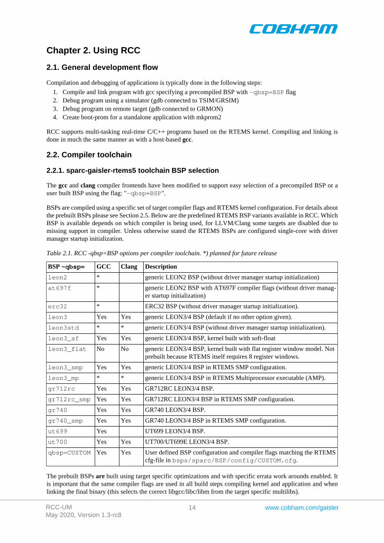
BSPs are compiled using a specific set of target compiler flags and RTEMS kernel configuration. For details aboutthe prebuilt BSPs please see Section 2.5. Below are the predefined RTEMS BSP variants available in RCC. WhichBSP is available depends on which compiler is being used, for LLVM/Clang some targets are disabled due tomissing support in compiler. Unless otherwise stated the RTEMS BSPs are configured single-core with drivermanager startup initialization.
Table 2.1. RCC -qbsp=BSP options per compiler toolchain. *) planned for future release
BSP -qbsp= GCC Clang Description
leon2 * generic LEON2 BSP (without driver manager startup initialization)
at697f * generic LEON2 BSP with AT697F compiler flags (without driver manag-er startup initialization)
erc32 * ERC32 BSP (without driver manager startup initialization).
leon3 Yes Yes generic LEON3/4 BSP (default if no other option given).
leon3std * * generic LEON3/4 BSP (without driver manager startup initialization).
leon3_sf Yes Yes generic LEON3/4 BSP, kernel built with soft-float
leon3_flat No No generic LEON3/4 BSP, kernel built with flat register window model. Notprebuilt because RTEMS itself requires 8 register windows.
leon3_smp Yes Yes generic LEON3/4 BSP in RTEMS SMP configuration.
leon3_mp * * generic LEON3/4 BSP in RTEMS Multiprocessor executable (AMP).
gr712rc Yes Yes GR712RC LEON3/4 BSP.
gr712rc_smp Yes Yes GR712RC LEON3/4 BSP in RTEMS SMP configuration.
gr740 Yes Yes GR740 LEON3/4 BSP.
gr740_smp Yes Yes GR740 LEON3/4 BSP in RTEMS SMP configuration.
ut699 Yes UT699 LEON3/4 BSP.
ut700 Yes Yes UT700/UT699E LEON3/4 BSP.
qbsp=CUSTOM Yes Yes User defined BSP configuration and compiler flags matching the RTEMScfg-file in bsps/sparc/BSP/config/CUSTOM.cfg.
The prebuilt BSPs are built using target specific optimizations and with specific errata work arounds enabled. Itis important that the same compiler flags are used in all build steps compiling kernel and application and whenlinking the final binary (this selects the correct libgcc/libc/libm from the target specific multilibs).
RCC-UMMay 2020, Version 1.3-rc8
15 www.cobham.com/gaisler
The RTEMS BSP build configuration file is found relative the RTEMS source tree bsps/sparc/BSP/con-fig/BSP.cfg. When setting custom build flags it is copied/renamed and updated to reflect the compiler flagsused when building a custom RTEMS kernel/BSP. The name of the configuration file is used as input to theRTEMS configure script's --enable-rtemsbsps="CUSTOM". See Section 1.2 for build and installation in-structions.
2.2.2. Common compiler options
Below are some SPARC/LEON specific and some other commonly used compiler options available on both GCCand Clang. For compiler specific flags see GCC Section 2.2.3.1 and Clang Section 2.2.4.2
-g generate debugging information - must be used for debugging with gdb.
-msoft-float emulate floating-point - must be used if no FPU exists in the system.
-mcpu=v8/none generate SPARC V8 mul/div instructions and SUN SPARC timings.
-mflat Enables flat register window model. SAVE/RESTORE instructions will not begenerated by compiler. It is ABI compliant with the SPARC ABI.
-O2 optimize code - should be used for optimum performance and combination ofsmall code size.
-Os optimize code for size - should be used for minimum code size.
For a full explaination and listing of compiler options see respective compiler manual, referenced from Section 1.5.
2.2.3. GNU GCC toolchain
2.2.3.1. sparc-gaisler-rtems5-gcc specific options
The GCC mcpu= options determines the instruction set (ISA) generated by the compiler whereas the -mfix-TARGET options determine target specific work arounds and compiler configurations. Below are the SPARC/LEON specific and some other commonly used GCC options:
-mcpu=v7/none generate SPARC V7 instructions. This ISA should be compilant with all LEONtargets. (default)
-mcpu=v8 generate SPARC V8 mul/div instructions and SUN SPARC timings.
-mcpu=leon generate SPARC V8 mul/div instructions and LEON timings.
-mcpu=leon3 generate SPARC V8 mul/div and CAS/CASA instructions and LEON3 timings.
-mcpu=leon3v7 generate SPARC V7 with CAS/CASA instructions and LEON3 timings.
-mfix-ut699 Enables work arounds for the UT699, for example the UT699 floating-point erra-ta, the UT699 data cache nullify errata and the LEON3FT B2BST errata.
-mfix-ut700 Enables all work arounds for the UT700/UT699e.
-mfix-gr712rc Enables all work arounds for the GR712RC (TN-0009, TN-0010, TN-0012 andTN-0013).Note: TN-0018 is worked around by run-time.
For a full explaination and listing of GNU GCC options see the gcc manual (gcc.pdf) referenced from Sec-tion 1.5.
2.2.3.2. LEON target GNU GCC compiler options
Below is a summary of commly used LEON chips and their specific compiler options.
AT697F -mcpu=leon -mfix-at697f
GR712RC -mcpu=leon3 -mfix-gr712rc
GR740 -mcpu=leon3
UT699 -mcpu=leon -mfix-ut699
RCC-UMMay 2020, Version 1.3-rc8
16 www.cobham.com/gaisler
UT700/UT699E -mcpu=leon3 -mfix-ut700
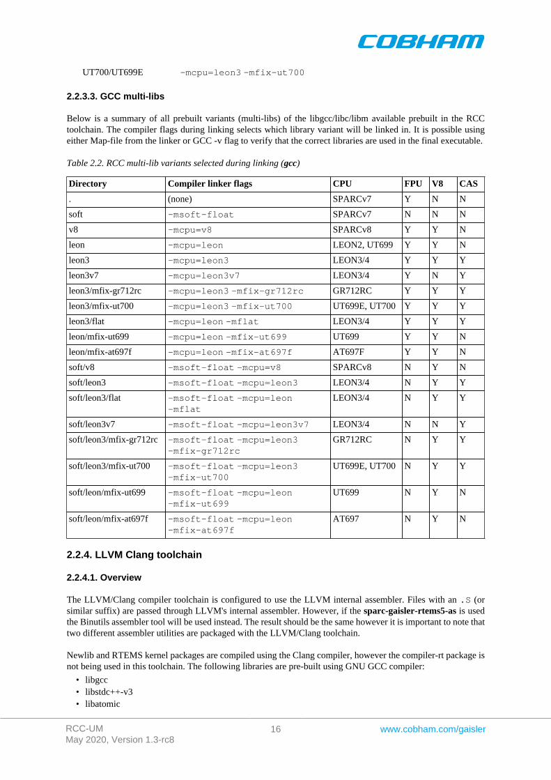
2.2.3.3. GCC multi-libs
Below is a summary of all prebuilt variants (multi-libs) of the libgcc/libc/libm available prebuilt in the RCCtoolchain. The compiler flags during linking selects which library variant will be linked in. It is possible usingeither Map-file from the linker or GCC -v flag to verify that the correct libraries are used in the final executable.
Table 2.2. RCC multi-lib variants selected during linking (gcc)
Directory Compiler linker flags CPU FPU V8 CAS
. (none) SPARCv7 Y N N
soft -msoft-float SPARCv7 N N N
v8 -mcpu=v8 SPARCv8 Y Y N
leon -mcpu=leon LEON2, UT699 Y Y N
leon3 -mcpu=leon3 LEON3/4 Y Y Y
leon3v7 -mcpu=leon3v7 LEON3/4 Y N Y
leon3/mfix-gr712rc -mcpu=leon3 -mfix-gr712rc GR712RC Y Y Y
leon3/mfix-ut700 -mcpu=leon3 -mfix-ut700 UT699E, UT700 Y Y Y
leon3/flat -mcpu=leon -mflat LEON3/4 Y Y Y
leon/mfix-ut699 -mcpu=leon -mfix-ut699 UT699 Y Y N
leon/mfix-at697f -mcpu=leon -mfix-at697f AT697F Y Y N
soft/v8 -msoft-float -mcpu=v8 SPARCv8 N Y N
soft/leon3 -msoft-float -mcpu=leon3 LEON3/4 N Y Y
soft/leon3/flat -msoft-float -mcpu=leon-mflat
LEON3/4 N Y Y
soft/leon3v7 -msoft-float -mcpu=leon3v7 LEON3/4 N N Y
soft/leon3/mfix-gr712rc -msoft-float -mcpu=leon3-mfix-gr712rc
GR712RC N Y Y
soft/leon3/mfix-ut700 -msoft-float -mcpu=leon3-mfix-ut700
UT699E, UT700 N Y Y
soft/leon/mfix-ut699 -msoft-float -mcpu=leon-mfix-ut699
UT699 N Y N
soft/leon/mfix-at697f -msoft-float -mcpu=leon-mfix-at697f
AT697 N Y N
2.2.4. LLVM Clang toolchain
2.2.4.1. Overview
The LLVM/Clang compiler toolchain is configured to use the LLVM internal assembler. Files with an .S (orsimilar suffix) are passed through LLVM's internal assembler. However, if the sparc-gaisler-rtems5-as is usedthe Binutils assembler tool will be used instead. The result should be the same however it is important to note thattwo different assembler utilities are packaged with the LLVM/Clang toolchain.
Newlib and RTEMS kernel packages are compiled using the Clang compiler, however the compiler-rt package isnot being used in this toolchain. The following libraries are pre-built using GNU GCC compiler:
• libgcc• libstdc++-v3• libatomic
RCC-UMMay 2020, Version 1.3-rc8
17 www.cobham.com/gaisler
2.2.4.2. sparc-gaisler-rtems5-clang specific options
The LLCM clang -mcpu= options determines the instruction set (ISA) other target specific options such as workarounds and compiler configurations. SPARCv7 is not supported currently by Clang. Below are the SPARC/LEONspecific and some other commonly used LLVM/Clang options:
-mcpu=leon3 generate SPARC V8 mul/div and CAS/CASA instructions and LEON3 timings.
-mcpu=gr712rc Build for target for GR712RC. Enables all work arounds for the GR712RC(TN-0009, TN-0010, TN-0012 and TN-0013).Note: TN-0018 is worked around by run-time.
-mcpu=gr740 Build for target for GR740.
-mfix-ut700 Build for target for UT700 and UT699E. Enables all work arounds for theUT700/UT699E that are applicable to the environment (TN-0009, TN-0010 andTN-0013).Note: TN-0018 is worked around by run-time.
-Oz Clang optimize code for size more than Os - should be used for minimum codesize.
For a full explaination and listing of LLVM/Clang options see the Clang manual referenced from Section 1.5.
2.2.4.3. LEON target LLVM Clang compiler options
Below is a summary of commly used LEON chips and their specific compiler options.
AT697F Not supported.
GR712RC -mcpu=gr712rc
GR740 -mcpu=gr740
UT700/UT699E -mcpu=leon3 -mfix-ut700
UT699 Not currently supported. Use -mcpu=leon3 for experimental use.
SPARCv7 Not supported. (Only SPARCv8 target support)
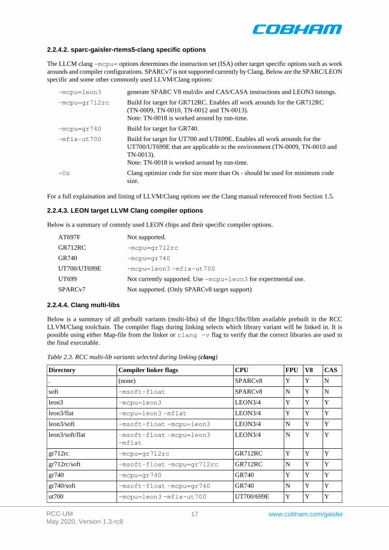
2.2.4.4. Clang multi-libs
Below is a summary of all prebuilt variants (multi-libs) of the libgcc/libc/libm available prebuilt in the RCCLLVM/Clang toolchain. The compiler flags during linking selects which library variant will be linked in. It ispossible using either Map-file from the linker or clang -v flag to verify that the correct libraries are used inthe final executable.
Table 2.3. RCC multi-lib variants selected during linking (clang)
Directory Compiler linker flags CPU FPU V8 CAS
. (none) SPARCv8 Y Y N
soft -msoft-float SPARCv8 N Y N
leon3 -mcpu=leon3 LEON3/4 Y Y Y
leon3/flat -mcpu=leon3 -mflat LEON3/4 Y Y Y
leon3/soft -msoft-float -mcpu=leon3 LEON3/4 N Y Y
leon3/soft/flat -msoft-float -mcpu=leon3-mflat
LEON3/4 N Y Y
gr712rc -mcpu=gr712rc GR712RC Y Y Y
gr712rc/soft -msoft-float -mcpu=gr712rc GR712RC N Y Y
gr740 -mcpu=gr740 GR740 Y Y Y
gr740/soft -msoft-float -mcpu=gr740 GR740 N Y Y
ut700 -mcpu=leon3 -mfix-ut700 UT700/699E Y Y Y
RCC-UMMay 2020, Version 1.3-rc8
18 www.cobham.com/gaisler
Directory Compiler linker flags CPU FPU V8 CAS
ut700/soft -msoft-float -mcpu=leon3-mfix-ut700
UT700/699E N Y Y
2.2.5. Floating-point considerations
If the targeted processor has no floating-point (FP) hardware, then all code must be compiled (and linked) withthe -msoft-float option to enable floating-point emulation by SW. When running the program on the TSIMsimulator, the simulator should be started with the -nfp option (no floating-point) to disable the FPU.
RTEMS saves the FPU register file and FSR register cross context switches and disables the FPU temporarilyduring interrupts to avoid that a faulty ISR trash the FPU state. If an ISR needs to use FPU it is responsible to saveand restore the FPU context itself using the RTEMS API. Due to the SPARC ABI the OS only needs to save theFPU context on interrupts since the ABI states that FPU conext is clobbered on function calls.
When creating RTEMS classic tasks the RTEMS_FLOATING_POINT option must be set if the task will executeFP instructions. Otherwise the CPU will generate a fp_disabled trap (trap type tt=0x04) on the first FP instructionexecuted by the task.
The RTEMS Init() task is by default configured without the RTEMS_FLOATING_POINT option. To enableRTEMS_FLOATING_POINT in the Init() task, the following configuration statement can be used:
#define CONFIGURE_INIT_TASK_ATTRIBUTES RTEMS_FLOATING_POINT
Note that the pre-built RTEMS BSPs that comes with RCC are built using the floating point instructions. Thismeans calling RTEMS kernel libraries may contains floating point instructions which requires the calling task tohave a floating point context (RTEMS_FLOATING_POINT) to avoid an exception. This also applies to the stringformatting functions of the C standard library, such as printf().
2.2.6. SPARC V8 instructions
LEON2/3/4 processors can be configured to implement the SPARC V8 multiply and divide instructions. Depend-ing on the compiler options (see above sections) the compiler will either generate or not those instructions oremulate them trough a SW library part of libgcc. Using the MUL/DIV improves performance significantly oncompute-intensive applications and floating-point emulation.
RTEMS saves the MUL/DIV (%y) register state cross context switches and on interrupts to protect against ISRoverwriting the MUL/DIV state.
2.2.7. LEON CASA instruction
Recent LEON3 and all LEON4 processors can be configured to implement the CASA instruction using the sameinstruction definitions as SPARC V9. The instruction is used to implement atomic Compare-And-Swap (CAS)operations. The compiler typically generates CAS instruction when compiling atomic C11/C++11 code otherwisethey are not generated. The spin-lock implementation of RTEMS SMP is implemented using C11 atomics. There-fore RTEMS SMP requires CAS hardware support.
2.2.8. LEON UMAC/SMAC instructions
LEON2/3/4 models supports optionally the 32-bit multiply and accumulate (MAC). The compiler never issuethose instructions, they have to be coded in assembly. The GNU Binutils; and LLVM assembler supports theLEON MAC instructions.
The RTEMS OS does not save the HW state of the MAC registers cross context switches.
2.2.9. LEON3/4 CPU counter
Some of the LEON3/4 devices (GR740/GR716 for example) supports reading a CPU internal 56-bit or 32-bit cyclecounter, without accessing the bus. The counters are located in the special registers ASR22:23 and are accessibleusing the rd instruction by assembly code.
The LLVM/Clang compiler also provides access to the cpu cycle counters by generating rd %asr22/23 in-structions when calling the builin function __builtin_readcyclecounter().
RCC-UMMay 2020, Version 1.3-rc8
19 www.cobham.com/gaisler
The RTEMS OS uses the counters when available, otherwise it defaults to an ordinary timer. The LEON3 BSP(bsp/leon.h) provides inline functions to allow the user application to access them easily (regardless of com-piler being used):
static inline uint32_t leon3_up_counter_low(void)
static inline uint32_t leon3_up_counter_high(void);
2.2.10. Enabling/Disabling Interrupt by use of Write Partial PSR instruction
The SPARCv8 requires that the whole Processor Status Register is read or written. However with some of theLEON3/4 devices (GR740/GR716 for example) it is now also possible to modify only parts of the PSR by using thePartial Write Register instruction (pwr %psr). The instruction is compatible with the definition in the SPARCv8especification.
By modify only the PIL field of the PSR the code can execute with traps enable (PSR.ET=1) and still guarantueethat the state of PSR is well defined even if traps do occur while modifying PSR. In SPARCv8 the read-modi-fy-write operation takes several instructions and has to be carried out by trap handlers where traps are disabled. ThePWR allows users and run-times to shorten the time interrupt is disabled and allows more efficient critical sections.
The GNU Binutils and LLVM assembler supports the generating the instruction by means of assembly code.Currently the RTEMS OS or BSP does not use this instruction.
2.3. RTEMS applications
To compile and link an RTEMS application, use sparc-gaisler-rtems5-gcc:
$ sparc-gaisler-rtems5-gcc -g -O2 rtems-hello.c -o rtems-hello
RCC creates executables for LEON3/4 by default. To generate executables for another target/BSP add the -qbsp=BSP switch during both the compile and link stages, see Section 2.2 for options. The load start address isspecified by the BSP. The default BSP load address is start of RAM, i.e. 0x40000000 LEON2/3/4 or 0x00000000for GR740 or 0x2000000 for ERC32. Other load addresses can be specified through the use of the -Ttext option(see GCC manual).
RCC uses the sources of RTEMS-5.0 with minor patches, and allows recompilation when user has modificatiionsor configuration changes to the BSP or the kernel. Install the RTEMS sources in /opt/rcc-1.3-rc8/src, and rebuildand install with:
$ cd /opt/rcc-1.3/src $ build-rtems.sh
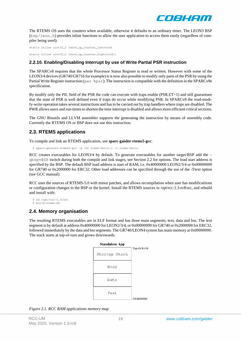
2.4. Memory organisation
The resulting RTEMS executables are in ELF format and has three main segments; text, data and bss. The textsegment is by default at address 0x40000000 for LEON2/3/4, or 0x00000000 for GR740 or 0x2000000 for ERC32,followed immediately by the data and bss segments. The GR740/LEON4 system has main memory at 0x00000000.The stack starts at top-of-ram and grows downwards.
Figure 2.1. RCC RAM applications memory map
RCC-UMMay 2020, Version 1.3-rc8
20 www.cobham.com/gaisler
The SPARC trap table always occupies the first 4 Kbytes of the .text segment and is modified during run-time.
The LEON BSPs auto-detects end-of-ram by looking at the stack pointer provided by the bootloader or GRMONat early boot. Hence the heap will be sized by the loader.
2.5. Board-support packages (BSPs)
RCC includes board support packages for LEON2, LEON3 and ERC32. LEON4 is supported by the LEON3 BSP.BSPs provide interface between RTEMS and target hardware through initialization code specific to the targetprocessor and a number of device drivers. Console and timer drivers are supported for all processors.
LEON2 and ERC32 BSPs assume a default system resource configuration such as memory mapping of on-chipdevices and usage of interrupt resources. LEON3/4 systems are based on GRLIB Plug & Play configuration, andare thereby highly configurable regarding memory mapping and interrupt routing. At start-up, the LEON3 BSPscans the system bus to obtain system configuration information. Device drivers support a number of deviceswhich are automatically recognized, initiated and handled by the device drivers. Plug and play makes it possibleto use the same BSP for GR712RC, UT699, UT699E/UT700 and GR740 but compiled with different flags.
See Section 2.2.1 on how to select which BSP and compiler flags Section 2.2.2.
See doc/rcc-drivers-1.3-rc8.pdf for GRLIB/LEON device driver API documentation.
2.5.1. LEON3 BSP
The LEON3 BSP includes two different console and timer drivers, 1) standard RTEMS drivers (-qbsp=leon3std) and 2) drivers which rely on the driver manager. The latter drivers are possible to config-ure from the project configuration using standard driver manager configuration options, for example which AP-BUART device is mapped to /dev/console and which timer is used as system clock (configuration requiredfor AMP systems).
The APBUART console driver registers the first UART under name /dev/console, the second and thirdUARTs get names /dev/console_b and dev/console_c and so on. The LEON3 BSP requires at least oneAPBUART to implement system console and printk support.
The timer driver uses the General Purpose Timer (GPTIMER and GRTIMER). The driver handles GPTIMERtimer 0 and the lowest interrupt request line used by GPTIMER. GPT timer 0 and lowest request line should neverbe used by an RTEMS application. If an application needs to use more timers GPT should be configured to havetwo or more timers using separate request lines. Timer 0 interrupt can not be shared with other devices or GPTtimers 1-6.
For more information on how to configure a system based on GRLIB see GRLIB IP Library User's Manual.
The rest of the GRLIB/LEON device drivers are independent of the BSP but dependent on driver manager API forinitialization order etc. The RTEMS project configuration selects which drivers are linked in to final executableimage. Please see separate drivers documentation for details.
2.5.1.1. Multi processing (ASMP and SMP) configurations
The LEON3 BSP supports the RTEMS SMP and ASMP configurations. See the multi-processing Section 2.9 formore information.
2.5.2. GR740 BSP
GR740 systems are supported by the LEON3 Plug & Play BSP, a custom linker script, the drivers listed below,specific compiler flags and the LEON3 BSP GR740 initialization code. At start-up for example, the RTEMScounter API initialization code checks the timers/counters present in HW and selects the best option. For the GR740the best counter is the ASR22:23 up-counter which is selected for optimum performance. This is an example ofhow the LEON3 BSP is adapted to the GR740 by use of Plug & Play probing.
RCC-UMMay 2020, Version 1.3-rc8
21 www.cobham.com/gaisler
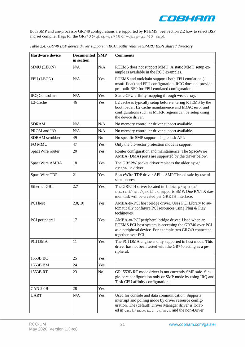
Both SMP and uni-processor GR740 configurations are supported by RTEMS. See Section 2.2 how to select BSPand set compiler flags for the GR740 (-qbsp=gr740 or -qbsp=gr740_smp).
Table 2.4. GR740 BSP device driver support in RCC, paths relative SPARC BSPs shared directory
Hardware device Documentedin section
SMP Comments
MMU (LEON) N/A N/A RTEMS does not support MMU. A static MMU setup ex-ample is available in the RCC examples.
FPU (LEON) N/A Yes RTEMS and toolchain supports both FPU emulation (-msoft-float) and FPU configuration. RCC does not providepre-built BSP for FPU emulated configuration.
IRQ Controller N/A Yes Static CPU affinity mapping through weak array.
L2-Cache 46 Yes L2 cache is typically setup before entering RTEMS by theboot loader. L2 cache maintainence and EDAC error andconfigurations such as MTRR regions can be setup usingthe device driver.
SDRAM N/A N/A No memory controller driver support available.
PROM and I/O N/A N/A No memory controller driver support available.
SDRAM scrubber 49 No No specific SMP support, single task API.
I/O MMU 47 Yes Only the bit-vector protection mode is support.
SpaceWire router 20 Yes Router configuration and maintainence. The SpaceWireAMBA (DMA) ports are supported by the driver below.
SpaceWire AMBA 18 Yes The GRSPW packet driver replaces the older spw/grspw.c driver.
SpaceWire TDP 21 Yes SpaceWire TDP driver API is SMP/Thread safe by use ofsemaphores.
Ethernet GBit 2.7 Yes The GRETH driver located in libbsp/sparc/shared/net/greth.c supports SMP. One RX/TX dae-mon task will be created per GRETH interface.
PCI host 2.8, 10 Yes AMBA-to-PCI host bridge driver. Uses PCI Library to au-tomatically configure PCI resources using Plug & Playtechinques.
PCI peripheral 17 Yes AMBA-to-PCI peripheral bridge driver. Used when anRTEMS PCI host system is accessing the GR740 over PCIas a peripheral device. For example two GR740 connectedtogether over PCI.
PCI DMA 11 Yes The PCI DMA engine is only supported in host mode. Thisdriver has not been tested with the GR740 acting as a pe-ripheral.
1553B BC 25 Yes
1553B BM 24 Yes
1553B RT 23 No GR1553B RT mode driver is not currently SMP safe. Sin-gle-core configuration only or SMP mode by using IRQ andTask CPU affinity configuration.
CAN 2.0B 28 Yes
UART N/A Yes Used for console and data communication. Supportsinterrupt and polling mode by driver resource config-uration. The (default) Driver Manager driver is locat-ed in uart/apbuart_cons.c and the non-Driver
RCC-UMMay 2020, Version 1.3-rc8
22 www.cobham.com/gaisler
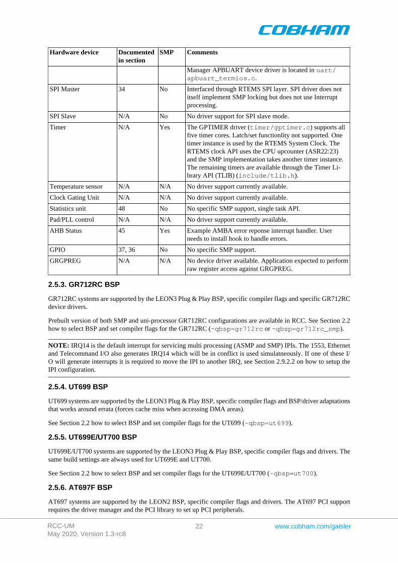
Hardware device Documentedin section
SMP Comments
Manager APBUART device driver is located in uart/apbuart_termios.c.
SPI Master 34 No Interfaced through RTEMS SPI layer. SPI driver does notitself implement SMP locking but does not use Interruptprocessing.
SPI Slave N/A No No driver support for SPI slave mode.
Timer N/A Yes The GPTIMER driver (timer/gptimer.c) supports allfive timer cores. Latch/set functionlity not supported. Onetimer instance is used by the RTEMS System Clock. TheRTEMS clock API uses the CPU upcounter (ASR22:23)and the SMP implementation takes another timer instance.The remaining timers are available through the Timer Li-brary API (TLIB) (include/tlib.h).
Temperature sensor N/A N/A No driver support currently available.
Clock Gating Unit N/A N/A No driver support currently available.
Statistics unit 48 No No specific SMP support, single task API.
Pad/PLL control N/A N/A No driver support currently available.
AHB Status 45 Yes Example AMBA error reponse interrupt handler. Userneeds to install hook to handle errors.
GPIO 37, 36 No No specific SMP support.
GRGPREG N/A N/A No device driver available. Application expected to performraw register access against GRGPREG.
2.5.3. GR712RC BSP
GR712RC systems are supported by the LEON3 Plug & Play BSP, specific compiler flags and specific GR712RCdevice drivers.
Prebuilt version of both SMP and uni-processor GR712RC configurations are available in RCC. See Section 2.2how to select BSP and set compiler flags for the GR712RC (-qbsp=gr712rc or -qbsp=gr712rc_smp).
NOTE: IRQ14 is the default interrupt for servicing multi processing (ASMP and SMP) IPIs. The 1553, Ethernetand Telecommand I/O also generates IRQ14 which will be in conflict is used simulatneously. If one of these I/O will generate interrupts it is required to move the IPI to another IRQ, see Section 2.9.2.2 on how to setup theIPI configuration.
2.5.4. UT699 BSP
UT699 systems are supported by the LEON3 Plug & Play BSP, specific compiler flags and BSP/driver adaptationsthat works around errata (forces cache miss when accessing DMA areas).
See Section 2.2 how to select BSP and set compiler flags for the UT699 (-qbsp=ut699).
2.5.5. UT699E/UT700 BSP
UT699E/UT700 systems are supported by the LEON3 Plug & Play BSP, specific compiler flags and drivers. Thesame build settings are always used for UT699E and UT700.
See Section 2.2 how to select BSP and set compiler flags for the UT699E/UT700 (-qbsp=ut700).
2.5.6. AT697F BSP
AT697 systems are supported by the LEON2 BSP, specific compiler flags and drivers. The AT697 PCI supportrequires the driver manager and the PCI library to set up PCI peripherals.
RCC-UMMay 2020, Version 1.3-rc8
23 www.cobham.com/gaisler
See Section 2.2 how to select BSP and set compiler flags for the AT697 (-qbsp=at697f).
2.6. Driver Manager
The LEON3 BSP uses an optional Driver Manger that handles drivers and devices on the AMBA and PCI Plug& Play buses. The drivers are automatically assigned to one or more hardware devices. The Driver Manager iseither initilized by the user from the Init() thread after RTEMS has started up, or during startup of RTEMS. Theprecompiled LEON3 BSP has by default (see Section 2.2.1) the driver manager enabled (--enable-drvmgrwas given to RTEMS configure during compile-time) that means that no extra initialization calls from Init() isneeded, however which drivers to be included must be configured uniquely per project. By default the Timer andUART drivers are included for system clock and console. One can use -qbsp=leon3std to avoid using thedriver manager. In most cases the GPTIMER and the APBUART drivers are required by the application.
If the driver manager was configured to be initialized by the BSP, the RTEMS_DRVMGR_STARTUP define isdefined. If not configured the define is not set and the user can choose to initialize the driver manager manuallyfrom for example the Init() task or not use it at all.
LEON2 systems are divided into two different systems, standard LEON2 systems and GRLIB-LEON2 systemswhere the AMBA Plug & Play bus is available. Both systems can use the LEON2 hardcoded bus with the DriverManager, however it's primary intention is to provide a root bus for a second bus supporting Plug & Play. Forexample a GRLIB-LEON2 system has hardcoded peripherals (the standard LEON2 peripherals) and GRLIB coresattached available from the AMBA Plug & Play information, the setup for a system like that would be a LEON2hardcoded bus and a LEON2 AMBA Plug & Play sub bus. Once the AMBA Plug & Play bus is initialized alldevice and their drivers can be used the same way as in LEON3/4 systems.
For AT697 PCI systems the driver manager can be used to scan the PCI bus. If, for example, a RASTA PCIperipheral board is found with GRLIB devices the GRLIB device drivers can be reused on the LEON2/AT697system to provide I/O accesses similar to any LEON3/4 system with the same I/O interfaces.
The ERC32 BSP does not support the driver manager.
2.6.1. Initialization
Before the driver manager is initialized one must register a root bus driver so that the driver man-ager knows which bus to start search for devices at. For a LEON3 system this means callingambapp_grlib_root_register() with a configuration structure. The driver manager itself must also beinitialized by calling drvmgr_init() before any driver relying on the driver manager can be accessed. Themanager then calls each individual driver's register function one by one for initialization and registration. Thedriver functions are typically named DRIVER_register().
NOTE: As described previously this step is taken care of by the BSP when --enable-drvmgr was used atRTEMS configuration/build time.
2.6.2. Configuration
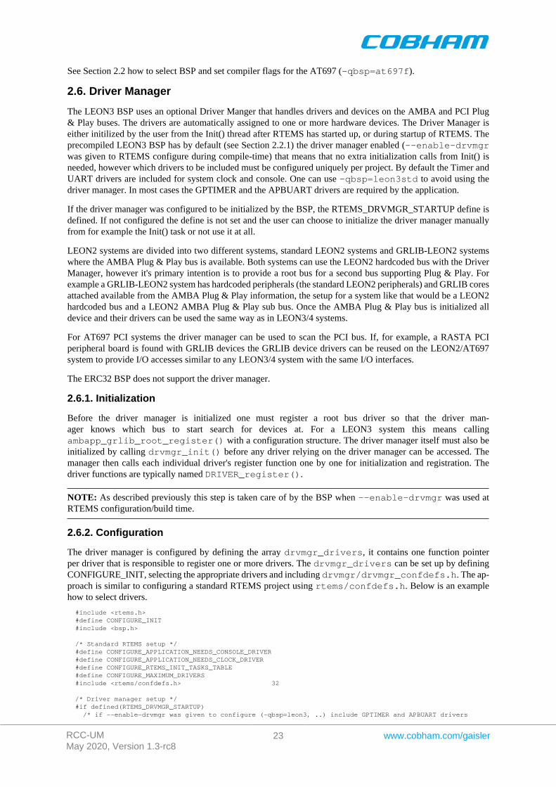
The driver manager is configured by defining the array drvmgr_drivers, it contains one function pointerper driver that is responsible to register one or more drivers. The drvmgr_drivers can be set up by definingCONFIGURE_INIT, selecting the appropriate drivers and including drvmgr/drvmgr_confdefs.h. The ap-proach is similar to configuring a standard RTEMS project using rtems/confdefs.h. Below is an examplehow to select drivers.
#include <rtems.h> #define CONFIGURE_INIT #include <bsp.h>
/* Standard RTEMS setup */ #define CONFIGURE_APPLICATION_NEEDS_CONSOLE_DRIVER #define CONFIGURE_APPLICATION_NEEDS_CLOCK_DRIVER #define CONFIGURE_RTEMS_INIT_TASKS_TABLE #define CONFIGURE_MAXIMUM_DRIVERS #include <rtems/confdefs.h> 32
/* Driver manager setup */ #if defined(RTEMS_DRVMGR_STARTUP) /* if --enable-drvmgr was given to configure (-qbsp=leon3, ..) include GPTIMER and APBUART drivers
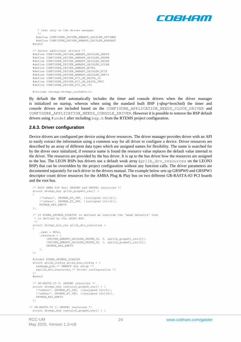
RCC-UMMay 2020, Version 1.3-rc8
24 www.cobham.com/gaisler
* that rely on the driver manager */ #define CONFIGURE_DRIVER_AMBAPP_GAISLER_GPTIMER #define CONFIGURE_DRIVER_AMBAPP_GAISLER_APBUART #endif
/* Select additional drivers */ #define CONFIGURE_DRIVER_AMBAPP_GAISLER_GRETH #define CONFIGURE_DRIVER_AMBAPP_GAISLER_GRSPW #define CONFIGURE_DRIVER_AMBAPP_GAISLER_GRCAN #define CONFIGURE_DRIVER_AMBAPP_GAISLER_OCCAN #define CONFIGURE_DRIVER_AMBAPP_MCTRL #define CONFIGURE_DRIVER_AMBAPP_GAISLER_PCIF #define CONFIGURE_DRIVER_AMBAPP_GAISLER_GRPCI #define CONFIGURE_DRIVER_PCI_GR_RASTA_IO #define CONFIGURE_DRIVER_PCI_GR_RASTA_TMTC #define CONFIGURE_DRIVER_PCI_GR_701
#include <drvmgr/drvmgr_confdefs.h>
By default the BSP automatically includes the timer and console drivers when the driver manageris initialized on startup, whereas when using the standard built BSP (-qbsp=leon3std) the timer andconsole drivers are included based on the CONFIGURE_APPLICATION_NEEDS_CLOCK_DRIVER andCONFIGURE_APPLICATION_NEEDS_CONSOLE_DRIVER. However it is possible to remove the BSP defaultdrivers using #undef after including bsp.h from the RTEMS project configuration.
2.6.3. Driver configuration
Device drivers are configured per device using driver resources. The driver manager provides driver with an APIto easily extract the information using a common way for all driver to configure a device. Driver resources aredescribed by an array of different data types which are assigned names for flexibility. The name is searched forby the driver once initialized, if resource name is found the resource value replaces the default value internal tothe driver. The resources are provided by the bus driver. It is up to the bus driver how the resources are assignedto the bus. The LEON BSPs bus drivers use a default weak array (grlib_drv_resources on the LEON3BSP) that can be overridden by the project configuration without any function calls. The driver parameters aredocumented separately for each driver in the drivers manual. The example below sets up GRSPW0 and GRSPW1descriptor count driver resources for the AMBA Plug & Play bus on two different GR-RASTA-IO PCI boardsand the root bus.
/* ROOT AMBA PnP Bus: GRSPW0 and GRSPW1 resources */ struct drvmgr_key grlib_grspw01_res[] = { {"txDesc", DRVMGR_KT_INT, {(unsigned int)32}}, {"rxDesc", DRVMGR_KT_INT, {(unsigned int)32}}, DRVMGR_KEY_EMPTY };
/* If RTEMS_DRVMGR_STARTUP is defined we override the "weak defaults" that * is defined by the LEON3 BSP. */ struct drvmgr_bus_res grlib_drv_resources = { .next = NULL, .resource = { {DRIVER_AMBAPP_GAISLER_GRSPW_ID, 0, &grlib_grspw01_res[0]}, {DRIVER_AMBAPP_GAISLER_GRSPW_ID, 1, &grlib_grspw01_res[0]}, DRVMGR_RES_EMPTY }, };
#ifndef RTEMS_DRVMGR_STARTUP struct grlib_config grlib_bus_config = { &ambapp_plb,/* AMBAPP bus setup */ &grlib_drv_resources,/* Driver configuration */ }; #endif
/* GR-RASTA-IO 0: GRSPW0 resources */ struct drvmgr_key rastaio0_grspw0_res[] = { {"txDesc", DRVMGR_KT_INT, {(unsigned int)8}}, {"rxDesc", DRVMGR_KT_INT, {(unsigned int)32}}, DRVMGR_KEY_EMPTY };
/* GR-RASTA-IO 1: GRSPW1 resources */ struct drvmgr_key rastaio0_grspw0_res[] = {
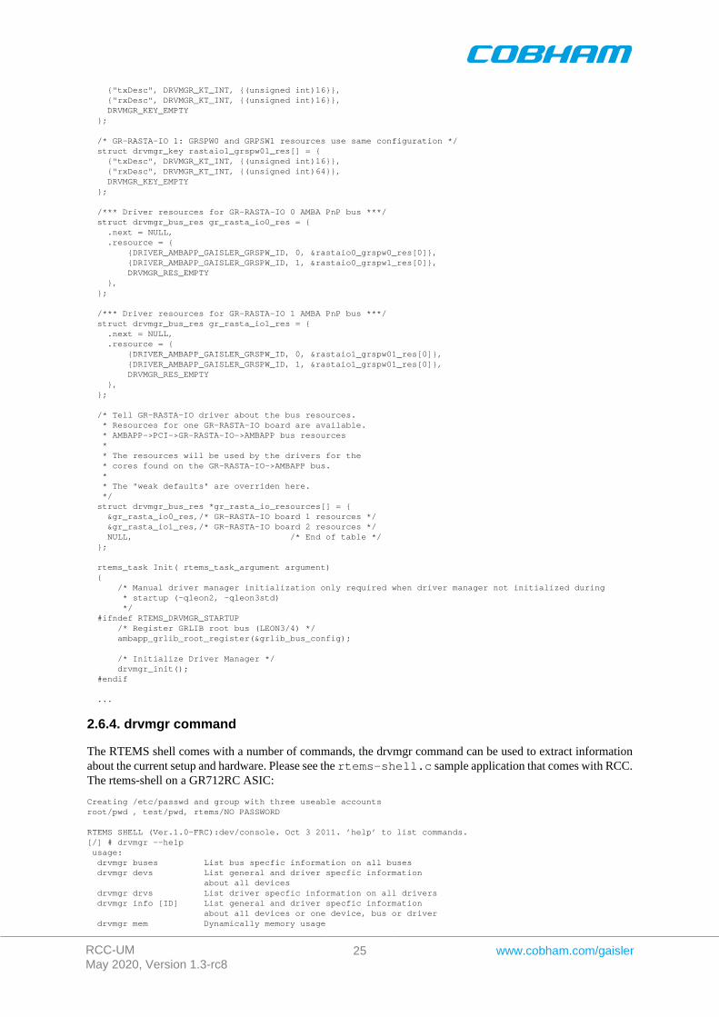
RCC-UMMay 2020, Version 1.3-rc8
25 www.cobham.com/gaisler
{"txDesc", DRVMGR_KT_INT, {(unsigned int)16}}, {"rxDesc", DRVMGR_KT_INT, {(unsigned int)16}}, DRVMGR_KEY_EMPTY };
/* GR-RASTA-IO 1: GRSPW0 and GRPSW1 resources use same configuration */ struct drvmgr_key rastaio1_grspw01_res[] = { {"txDesc", DRVMGR_KT_INT, {(unsigned int)16}}, {"rxDesc", DRVMGR_KT_INT, {(unsigned int)64}}, DRVMGR_KEY_EMPTY };
/*** Driver resources for GR-RASTA-IO 0 AMBA PnP bus ***/ struct drvmgr_bus_res gr_rasta_io0_res = { .next = NULL, .resource = { {DRIVER_AMBAPP_GAISLER_GRSPW_ID, 0, &rastaio0_grspw0_res[0]}, {DRIVER_AMBAPP_GAISLER_GRSPW_ID, 1, &rastaio0_grspw1_res[0]}, DRVMGR_RES_EMPTY }, };
/*** Driver resources for GR-RASTA-IO 1 AMBA PnP bus ***/ struct drvmgr_bus_res gr_rasta_io1_res = { .next = NULL, .resource = { {DRIVER_AMBAPP_GAISLER_GRSPW_ID, 0, &rastaio1_grspw01_res[0]}, {DRIVER_AMBAPP_GAISLER_GRSPW_ID, 1, &rastaio1_grspw01_res[0]}, DRVMGR_RES_EMPTY }, };
/* Tell GR-RASTA-IO driver about the bus resources. * Resources for one GR-RASTA-IO board are available. * AMBAPP->PCI->GR-RASTA-IO->AMBAPP bus resources * * The resources will be used by the drivers for the * cores found on the GR-RASTA-IO->AMBAPP bus. * * The "weak defaults" are overriden here. */ struct drvmgr_bus_res *gr_rasta_io_resources[] = { &gr_rasta_io0_res,/* GR-RASTA-IO board 1 resources */ &gr_rasta_io1_res,/* GR-RASTA-IO board 2 resources */ NULL, /* End of table */ };
rtems_task Init( rtems_task_argument argument) { /* Manual driver manager initialization only required when driver manager not initialized during * startup (-qleon2, -qleon3std) */ #ifndef RTEMS_DRVMGR_STARTUP /* Register GRLIB root bus (LEON3/4) */ ambapp_grlib_root_register(&grlib_bus_config);
/* Initialize Driver Manager */ drvmgr_init(); #endif
...
2.6.4. drvmgr command
The RTEMS shell comes with a number of commands, the drvmgr command can be used to extract informationabout the current setup and hardware. Please see the rtems-shell.c sample application that comes with RCC.The rtems-shell on a GR712RC ASIC:
Creating /etc/passwd and group with three useable accountsroot/pwd , test/pwd, rtems/NO PASSWORD
RTEMS SHELL (Ver.1.0-FRC):dev/console. Oct 3 2011. ’help’ to list commands.[/] # drvmgr --help usage: drvmgr buses List bus specfic information on all buses drvmgr devs List general and driver specfic information about all devices drvmgr drvs List driver specfic information on all drivers drvmgr info [ID] List general and driver specfic information about all devices or one device, bus or driver drvmgr mem Dynamically memory usage
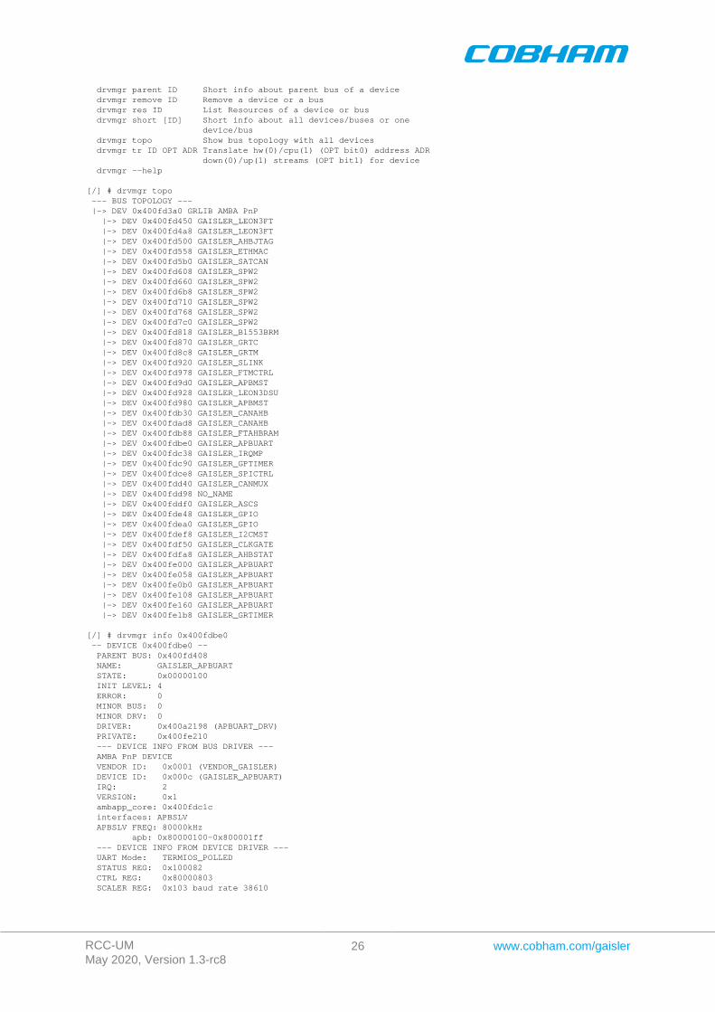
RCC-UMMay 2020, Version 1.3-rc8
26 www.cobham.com/gaisler
drvmgr parent ID Short info about parent bus of a device drvmgr remove ID Remove a device or a bus drvmgr res ID List Resources of a device or bus drvmgr short [ID] Short info about all devices/buses or one device/bus drvmgr topo Show bus topology with all devices drvmgr tr ID OPT ADR Translate hw(0)/cpu(1) (OPT bit0) address ADR down(0)/up(1) streams (OPT bit1) for device drvmgr --help
[/] # drvmgr topo --- BUS TOPOLOGY --- |-> DEV 0x400fd3a0 GRLIB AMBA PnP |-> DEV 0x400fd450 GAISLER_LEON3FT |-> DEV 0x400fd4a8 GAISLER_LEON3FT |-> DEV 0x400fd500 GAISLER_AHBJTAG |-> DEV 0x400fd558 GAISLER_ETHMAC |-> DEV 0x400fd5b0 GAISLER_SATCAN |-> DEV 0x400fd608 GAISLER_SPW2 |-> DEV 0x400fd660 GAISLER_SPW2 |-> DEV 0x400fd6b8 GAISLER_SPW2 |-> DEV 0x400fd710 GAISLER_SPW2 |-> DEV 0x400fd768 GAISLER_SPW2 |-> DEV 0x400fd7c0 GAISLER_SPW2 |-> DEV 0x400fd818 GAISLER_B1553BRM |-> DEV 0x400fd870 GAISLER_GRTC |-> DEV 0x400fd8c8 GAISLER_GRTM |-> DEV 0x400fd920 GAISLER_SLINK |-> DEV 0x400fd978 GAISLER_FTMCTRL |-> DEV 0x400fd9d0 GAISLER_APBMST |-> DEV 0x400fd928 GAISLER_LEON3DSU |-> DEV 0x400fd980 GAISLER_APBMST |-> DEV 0x400fdb30 GAISLER_CANAHB |-> DEV 0x400fdad8 GAISLER_CANAHB |-> DEV 0x400fdb88 GAISLER_FTAHBRAM |-> DEV 0x400fdbe0 GAISLER_APBUART |-> DEV 0x400fdc38 GAISLER_IRQMP |-> DEV 0x400fdc90 GAISLER_GPTIMER |-> DEV 0x400fdce8 GAISLER_SPICTRL |-> DEV 0x400fdd40 GAISLER_CANMUX |-> DEV 0x400fdd98 NO_NAME |-> DEV 0x400fddf0 GAISLER_ASCS |-> DEV 0x400fde48 GAISLER_GPIO |-> DEV 0x400fdea0 GAISLER_GPIO |-> DEV 0x400fdef8 GAISLER_I2CMST |-> DEV 0x400fdf50 GAISLER_CLKGATE |-> DEV 0x400fdfa8 GAISLER_AHBSTAT |-> DEV 0x400fe000 GAISLER_APBUART |-> DEV 0x400fe058 GAISLER_APBUART |-> DEV 0x400fe0b0 GAISLER_APBUART |-> DEV 0x400fe108 GAISLER_APBUART |-> DEV 0x400fe160 GAISLER_APBUART |-> DEV 0x400fe1b8 GAISLER_GRTIMER
[/] # drvmgr info 0x400fdbe0 -- DEVICE 0x400fdbe0 -- PARENT BUS: 0x400fd408 NAME: GAISLER_APBUART STATE: 0x00000100 INIT LEVEL: 4 ERROR: 0 MINOR BUS: 0 MINOR DRV: 0 DRIVER: 0x400a2198 (APBUART_DRV) PRIVATE: 0x400fe210 --- DEVICE INFO FROM BUS DRIVER --- AMBA PnP DEVICE VENDOR ID: 0x0001 (VENDOR_GAISLER) DEVICE ID: 0x000c (GAISLER_APBUART) IRQ: 2 VERSION: 0x1 ambapp_core: 0x400fdc1c interfaces: APBSLV APBSLV FREQ: 80000kHz apb: 0x80000100-0x800001ff --- DEVICE INFO FROM DEVICE DRIVER --- UART Mode: TERMIOS_POLLED STATUS REG: 0x100082 CTRL REG: 0x80000803 SCALER REG: 0x103 baud rate 38610

RCC-UMMay 2020, Version 1.3-rc8
27 www.cobham.com/gaisler
2.7. Network configuration
The LEON2/3 BSPs support three network devices: the Cobham Gaisler GRETH MAC, GRETH_GBIT MACand the LAN91C111 (note: 91C111 only in single-core configuration). The GRETH driver comes in two editions,one that needs the driver manager (in libbsp) to operate and the standard driver (in libchip). The driver man-ager dependent GRETH driver adds the network interface automatically to the rtems_bsdnet_config net-work interface configuration using network_interface_add() function. It also supports SMP. The driversunder libchip/ directory does not support SMP currently. Since the LAN91C111 chip is supported over the I/O bus it cannot be found by Plug & Play so it has to be manually set up by either hardcoding an entry in thertems_bsdnet_config interface list or dynamically registered by calling network_interface_add().The LAN91C111 attach routine is defined by RTEMS_BSP_NETWORK_DRIVER_ATTACH_SMC91111 inbsp.h. The standard GRETH device is setup in a similar way, see bsp.h.
See src/samples/rtems-ttcp.c for a sample networking application.
2.8. PCI
Cobham Gaisler provides a PCI Library together with RTEMS located in cpukit/libpci in the soruces. The doc-umentation for the PCI Library is located in the RTEMS documentation doc/usr/libpci.t and availableprebuilt into PDF named c_user.pdf, see Section 1.5.
All the LEON PCI host bridge drivers have been written using the driver manger and the PCI library is initializedusing the PCI bus layer for the driver manager. Even if the PCI Library does not require the driver manger thePCI host drivers does.
The RTEMS shell has been extended with a pci command can be used to extract information about the current setupand hardware. Please see the rtems-shell.c sample application that comes with RCC. A non-PCI system:
reating /etc/passwd and group with three useable accountsroot/pwd , test/pwd, rtems/NO PASSWORD
RTEMS SHELL (Ver.1.0-FRC):dev/console. Oct 3 2011. ’help’ to list commands. [/] # pci --help usage: pci ls [bus:dev:fun|PCIID] List one or all devices pci r{8|16|32} bus:dev:fun OFS Configuration space read pci r{8|16|32} PCIID OFS Configuration space read access by PCIID pci w{8|16|32} bus:dev:fun OFS D Configuration space write pci w{8|16|32} PCIID OFS D Configuration space write access by PCIID pci pciid bus:dev:fun Print PCIID for bus:dev:fun pci pciid PCIID Print bus:dev:fun for PCIID pci pcfg Print current PCI config for static configuration library pci getdev {PCIID|bus:dev:fun} Get PCI Device from RAM tree pci infodev DEV_ADR Info about a PCI RAM Device pci --help
[/] # pci SYSTEM: UNKNOWN / UNINITIALIZED CFG LIBRARY: AUTO NO. PCI BUSES: 0 buses PCI ENDIAN: Little MACHINE ENDIAN: Big
2.9. LEON3 BSP multiprocessing configurations
RTEMS supports uni-processor, asymmetric multiprocessing (ASMP) and Symmetric multiprocessing (SMP)configurations. The LEON3 BSP support all three modes. The ASMP mode can be accomplished in one of twopossible setups:
• Uni-processor configuration and custom synchonization/communication protocols between CPUs imple-mented by user. (-qbsp=BSP)
• RTEMS ASMP configuration where RTEMS services are used to synchonize and communicate between theCPU nodes. For example using global objects like global semaphores and global tasks and Inter ProcessorCommunication services implemented on top the shared memory (SHM) driver. (-qbsp=BSP_mp)
RCC-UMMay 2020, Version 1.3-rc8
28 www.cobham.com/gaisler
Note that in a multi-processor system with more than two CPUs RTEMS supports running SMP configuration ontwo or more processor in parallel with another OS instance on a different set of processors. This means SMP andASMP can cooexist in the same system.
2.9.1. Memory and device resource sharing
An ASMP application typically assigns different hardware resources to different operating system instances with-out overlap at compile-time. For example UART0/IRQ2 is used by CPU0 and UART1/IRQ3 by CPU1. In uni-processor and ASMP configuration the resource sharing between operating system instances are configured usingthe driver manager or by using the default configuration. Linker scripts or linker arguments are typically used toseparate address spaces between ASMP CPUs.
In SMP configuration RTEMS has typically access to all resources. Instead it uses locks and scheduler to share/protect resources between processors during run-time. This means that no specific driver manager configurationreleated to resource sharing is needed for SMP.
2.9.2. Interrupt considerations
2.9.2.1. Interrupt Controller IRQ(A)MP
The GRLIB IRQ(A)MP interrupt controller has extended ASMP support which allows for assigning individualisolated interrupt controllers on a processor basis. An individual isolated interrupt controller is also referred to as aninternal interrupt controller in the IRQ(A)MP documentation. For an RTEMS SMP application running in an AMPsetting, it is recommended to dedicate one of the virtual interrupt controllers to RTEMS SMP. RTEMS will detectwhich interrupt controller its processor is assigned to by probing the IRQ(A)MP Asymmetric multiprocessingcontrol register and the Interrupt controller select registers.
In SMP configuration, RTEMS assumes that the boot loader (MKPROM or GRMON) has assigned all the proces-sor part of the SMP system to the same (internal) interrupt controller. For example, the GR740 has a IRQ(A)MPwith four internal controllers but only one is used wqhen RTEMS SMP control all four CPUs.
2.9.2.2. Inter processor interrupt (IPI)
When RTEMS AMP/SMP requests to notify another CPU an interrupt is generated on the target CPU by writingthe interrupt controller's registers. The ISR handling IPI requests are typically associated with a "free" interruptnumber, i.e. not used for I/O interrupts. The interrupt is by default the highest interrupt number available, IRQ14.It is recommended to change to a dedicated IRQ if other (I/O) interrupt sources is also generating IRQ14.
The IPI interrupt is configurable on project compile time by overriding the weak variable LEON3_mp_irq witha custom IRQ number. For example include this code in the project to handle IPIs on IRQ11 on all RTEMS CPUs:
const unsigned char LEON3_mp_irq = 11;
2.9.2.3. Interrupt affinity (SMP only)
By default the boot CPU handles all interrupts (except for IPI and per-cpu iimer) in SMP configuration, thusnormally CPU0 handles all I/O interrupts. The LEON3 BSP uses a static interrupt affinity configuration tableto select which CPU will service a particular IRQ. LEON3_irq_to_cpu is a weak variable which translatesIRQ[I] to CPU[J]. It allows the user to override the default BSP behaviour during compile time. The table is usedwhen registering a new interrupt handler.
2.9.3. Symmetric multiprocessing (SMP) configuration
2.9.3.1. Processor selection
RTEMS SMP allows for a wide range of processor configuration arrangements in a multiproces-sor system. By default, an SMP application will execute on the processors with index 0 up toCONFIGURE_MAXIMUM_PROCESSORS-1, where CONFIGURE_MAXIMUM_PROCESSORS is a preprocessordefine which can be provided to the compiler using the -D option. The boot processor is normally CPU 0, butthere is no restriction on this: the first processor reaching the kernel entry point is assigned as the boot processor.
RCC-UMMay 2020, Version 1.3-rc8
29 www.cobham.com/gaisler
An RTEMS SMP application can be configured at compile time to assign different schedulers to specific setsof processors. This is described in detail in the RTEMS Classic API Guide 5 in the sections named Schedulingconcepts and Scheduler algorithm Configuration. In this RCC User's Manual we will assume usage of the thedefault scheduler. Processor assignments will be setup using a scheduler assignment table.
Processors are assigned to the application (scheduler) with the scheduler assignment table, specified us-ing the CONFIGURE_SCHEDULER_ASSIGNMENTS preprocessor define. The define shall contain a list ofRTEMS_SCHEDULER_ASSIGN(index, attr) and RTEMS_SCHEDULER_ASSIGN_NO_SCHEDULER en-tries. There is one entry for each processor in the range 0 to CONFIGURE_MAXIMUM_PROCESSORS-1.
The following example will assign RTEMS SMP to CPU1 and CPU2. CPU0 and CPU3 will not be used in theRTEMS SMP instance and can run operating system(s).
#define CONFIGURE_MAXIMUM_PROCESSORS 4 /* RTEMS SMP on CPU[1,2]. Something else on CPU[0,3]. */ #define CONFIGURE_SCHEDULER_ASSIGNMENTS \ RTEMS_SCHEDULER_ASSIGN_NO_SCHEDULER, \ RTEMS_SCHEDULER_ASSIGN(0, RTEMS_SCHEDULER_ASSIGN_PROCESSOR_MANDATORY), \ RTEMS_SCHEDULER_ASSIGN(0, RTEMS_SCHEDULER_ASSIGN_PROCESSOR_MANDATORY), \ RTEMS_SCHEDULER_ASSIGN_NO_SCHEDULER
For RTEMS_SCHEDULER_ASSIGN(index, attr), the index parame-ter selects one of the optionally configured schedulers, and the at-tr parameter is set to RTEMS_SCHEDULER_ASSIGN_PROCESSOR_MANDATORY orRTEMS_SCHEDULER_ASSIGN_PROCESSOR_OPTIONAL. A processor is not used in the application if its en-try in the list is RTEMS_SCHEDULER_ASSIGN_NO_SCHEDULER.
2.9.4. Asymmetric multiprocessing (AMP) configuration
RTEMS supports asymmetric multiprocessing (AMP), the LEON3 BSP supports AMP in two different setups.Either the RTEMS kernel is compiled with multiprocessing support (-qbsp=BSP_mp) or the user setup customresource sharing with driver manager resources (-qbsp=BSP), the difference is that RTEMS provide multiprocess-ing objects and communication channels in the former case and in the latter case the user is responsible for allsynchronization itself which in many cases are sufficient. All nodes in a asymmetric multiprocessor system exe-cutes thier own program image. Messages are passed between the nodes containing synchronization information,for example take global semaphore A. Messages are sent over memory using the Shared Memory Support Driverin the LEON3 BSP, and interrupts are used to alert the receiving CPU.
The kernel must be compiled with multiprocessing support in order for the RTEMS AMP support to be avail-able, the toolchain includes a precompiled LEON3 MP kernel in rcc-1.3-rc8/sparc-gaisler-rtems5/leon3_mp, it is the LEON3 BSP compiled with multiprocessing support. The MP kernel is selected when the -qbsp=BSP_mp argument is given to sparc-gaisler-rtems5-gcc.
Since each CPU executes its own program image, a memory area has to be allocated for each CPU's program imageand stack. This is achieved by linking each CPU's RTEMS program at the start addresses of the CPU's memoryarea and setting stack pointer to the top of the memory area. E.g. for two CPU system, the application runningon CPU 0 could run in memory area 0x40100000 - 0x401fffff, while CPU 1 runs in memory area 0x4020000 -0x402fffff. Shared Memory Support Driver allocates 4 KB buffer at address 0x40000000 for message passing(this area can not be used for applications).
Each CPU requires its own set of standard peripherals such as UARTs and timers. In an MP system the BSP willautomatically allocate UART 1 and GPT 0 timer 1 to CPU 0, UART 2 and GPT 0 timer 2 to CPU 1 and so on.When the default configuration does not meet the requirements or hardware setup a custom resource allocationcan be setup using the driver manager, see below.
The shared memory driver's default memory layout configuration can be overidden without recompiling the kernel.The default settings are set in the variable weak variable BSP_shm_cfgtbl, it can be overridden by definingBSP_shm_cfgtbl once in the project as in the below example. The parameters that has an effect in changingis the fields base and length.
/* Override default SHM configuration */ shm_config_table BSP_shm_cfgtbl = { .base = (void *)0x40000000, .length = 0x00010000
RCC-UMMay 2020, Version 1.3-rc8
30 www.cobham.com/gaisler
};
Hardware resource allocation is done by the BSP for UART, IRQ controller and System Clock Timer. Deviceswhich has a driver that is implemented using the driver manager can be ignored by a specific CPU by assigning thekeys value NULL in the driver resouces. The driver manager simply ignores the device when a NULL resource isdetect. An example is given below where CPU0 is assigned GRGPIO0 and CPU1 GRGPIO1. GPTIMER driverhave options that limit number of timers and which timer is used for system clock, the system console and debugoutput can be selected to a specific UART with the APBUART driver.
CPU0 Application:
struct rtems_drvmgr_drv_res grlib_drv_resources[] = { {DRIVER_AMBAPP_GAISLER_GRGPIO_ID, 1, NULL} /* Used by CPU1 */ };
CPU1 Application:
struct rtems_drvmgr_drv_res grlib_drv_resources[] = { {DRIVER_AMBAPP_GAISLER_GRGPIO_ID, 0, NULL}, /* Used by CPU0 */ {DRIVER_AMBAPP_GAISLER_GRGPIO_ID, 1, &grlib_drv_res_grgpio1[0]} };
Following example shows how to run RTEMS MP application on a two CPU system using GRMON. CPU 0executes image node1.exe in address space 0x6000000 - 0x600fffff while CPU 1 executes image node2.exe inaddress space 0x60100000 - 0x601fffff.
GRMON LEON debug monitor v1.1.22
Copyright (C) 2004,2005 Gaisler Research - all rights reserved.For latest updates, go to http://www.gaisler.comComments or bug-reports to [email protected]...
grlib> lo node1.exesection: .text at 0x60000000, size 143616 bytessection: .data at 0x60023100, size 3200 bytestotal size: 146816 bytes (174.4 kbit/s)read 852 symbolsentry point: 0x60000000grlib> lo node2.exesection: .text at 0x60100000, size 143616 bytessection: .data at 0x60123100, size 3200 bytestotal size: 146816 bytes (172.7 kbit/s)read 852 symbolsentry point: 0x60100000grlib> cpu act 0active cpu: 0grlib> ep 0x60000000entry point: 0x60000000grlib> stack 0x600fff00 stack pointer: 0x600fff00grlib> cpu act 1active cpu: 1grlib> ep 0x60100000entry point: 0x60100000grlib> stack 0x601fff00 stack pointer: 0x601fff00grlib> cpu act 0active cpu: 0grlib> run
RTEMS MP applications can not be run directly in GRSIM (using load and run commands). Instead a boot imagecontaining several RTEMS MP applications should be created and simulated.
2.9.4.1. MP testsuite
The MP testsuite is located in the sources under testsuite/mptests, it requires modifications to the make scripts inorder to select a unique image RAM location. The default shared memory area is at 0x40000000-0x40000fff, thetwo images for node1 and node2 needs to be located on a unique address and the heap/stack must also fit. Theargument -Wl,- Ttext,0x40001000 for node1 and -Wl,-Ttext,0x40200000 for node2 can be added to the link stage,and the entry point (0x40001000 and 0x40200000) and stacks (0x401ffff0 and 0x403ffff0) must also be set bythe loader (GRMON or mkprom for example). Depending on where the RAM memory is located and how muchmemory is available the parameters may vary.
RCC-UMMay 2020, Version 1.3-rc8
31 www.cobham.com/gaisler
2.9.5. RTEMS SMP AMP example
An AMP demonstration including RTEMS SMP targeting GR740 is distributed with RCC and is installed in the di-rectory src/samples/gr740/ampdemo. The demonstration consists of two applications: one single-proces-sor RTEMS application and one RTEMS SMP application. Two different AMP configurations are demonstrated:
ampdemo-smp0CPU0, CPU1 and CPU2 execute an RTEMS SMP application. CPU3 is started from the RTEMS SMPapplication and executes an independent single-processor application.
ampdemo-sp0CPU0 executes a single-processor application. CPU0 starts (wakes up) CPU1 which together with CPU2and CPU3 execute an RTEMS SMP application.
The purpose of the example is to demonstrate how RTEMS SMP can be used to start other operating systeminstances aswell as itself being a slave instance in an AMP setting. Initialization of the interrupt controller bymeans of GRMON commands is also demonstrated: this is typically performed by a boot loader when the systemis deployed. The preparation script configures a set of hardware breakpoints to assert that the operating systeminstances do not interfer with each others GPTIMER and APBUART and.
More information on how to run the RTEMS SMP AMP example is provided in src/samples/gr740/am-pdemo/README.
2.10. Making boot-proms
RTEMS applications are linked to run from beginning of RAM. To make a boot-PROM that will run from thePROM on a standalone target, use the mkprom2 utility freely available from www.gaisler.com. The mkpromutility is documented in a separate document that is distributed together with the mkprom2 utility. Mkprom willcreate a compressed boot image that will load the application into RAM, initiate various processor registers, andfinally start the application. Mkprom will set all target dependent parameters, such as memory sizes, wait-states,baudrate, and system clock. The applications do not set these parameters themselves, and thus do not need to bere-linked for different board architectures.
The example below creates a LEON3 boot-prom for a system with 1 Mbyte RAM, one waitstate during write, 3waitstates for rom access, and 40 MHz system clock. For more details see the mkprom manual
$ mkprom2 -ramsz 1024 -ramwws 1 -romws 3 -freq 40 hello.exe
Note that mkprom creates binaries for LEON2/3/4 and for ERC32, select processor type with the mkprom options-leon3, -leon2 or -erc32 flag. To create an SRECORD file for a prom programmer, use objcopy:
$ sparc-gaisler-rtems5-objcopy -O srec hello.exe hello.srec
RCC-UMMay 2020, Version 1.3-rc8
32 www.cobham.com/gaisler
Chapter 3. Examples
3.1. Overview
There is a samples collection distributed within the RCC under rcc-1.3-rc8/src/samples. It containssome general RTEMS examples and some more specific LEON or boards specific examples.
3.2. Building
Following example compiles the famous "hello world" program and creates a boot-prom in SRECORD format:
$ sparc-gaisler-rtems5-gcc -qbsp=leon3 -mcpu=leon3 -O2 rtems-hello.c -o rtems-hello $ mkprom2 -leon3 -freq 40 -dump -baud 38400 -ramsize 1024 -rmw rtems-hello $ sparc-gaisler-rtems5-objcopy -O srec rtems-hello rtems-hello.srec
Several example C programs can be found in /opt/rcc-1.3-rc8/src/samples. This folder also includesa Makefile that can be used to build the examples. Building the examples for a predefined BSP configurationis done by calling "make <bsp-target>". Calling make (without a target) will compile all the examplesfor all the pre-built BSPs. The CPU compiler flags are set to the same as when building the RTEMS BSP. Theexecutables will be stored bin/<bsp-target>. Valid bsp-targets are the same listed in Section 2.2.1 leon3,leon3_smp, gr712rc, gr712rc_smp, .. etc. Below is an example building for GR712RC
bash$ make gr712rcmake BSP=gr712rc ODIR=bin/gr712rc gr712rc_buildmake[1]: Entering directory '/home/daniel/git/rtems/build-1.3/src/samples'sparc-gaisler-rtems5-gcc -Wall -g -O2 -Werror -I./ -mcpu=leon3 -mfix-gr712rc \ -qbsp=gr712rc -DBRM_BM_TEST rtems-brm.c brm_lib.c -o bin/gr712rc/rtems-brm_bmsparc-gaisler-rtems5-gcc -Wall -g -O2 -Werror -I./ -mcpu=leon3 -mfix-gr712rc \ -qbsp=gr712rc rtems-brm.c brm_lib.c -o bin/gr712rc/rtems-brm_rtsparc-gaisler-rtems5-gcc -Wall -g -O2 -Werror -I./ -mcpu=leon3 -mfix-gr712rc \ -qbsp=gr712rc -DBRM_BC_TEST rtems-brm.c brm_lib.c -o bin/gr712rc/rtems-brm_bcsparc-gaisler-rtems5-gcc -Wall -g -O2 -Werror -I./ -mcpu=leon3 -mfix-gr712rc \ -qbsp=gr712rc -DTASK_TX -DTASK_RX rtems-occan.c occan_lib.c -o bin/gr712rc/rtems-occansparc-gaisler-rtems5-gcc -Wall -g -O2 -Werror -I./ -mcpu=leon3 -mfix-gr712rc \ -qbsp=gr712rc -DMULTI_BOARD -DTASK_TX rtems-occan.c occan_lib.c -o bin/gr712rc/rtems-occan_tx...make[1]: Leaving directory '/opt/rcc-1.3-rc2/src/samples'
It is also possible to build a single example by calling make <example> or to build a prom image by callingmake <example>.mkprom. In this case the executables will be stored in the root samples directory. Whenbuilding individual examples it is possible to control the behaviour by setting the following variables.
BSPBy setting the BSP variable to one of the bsp-targets, then the hardware specific compilation flags for thatcpu-target will be added when compiling and the matchin -qbsp=BSP flag will be added.
CFLAGSOverride common compilation flags
CPUFLAGSOverride the hardware specific compilation flags
MKPROMFLAGSOverride mkprom2 flags
ODIRExecutables output directory. By default bin/BSP/.
Below is the command line for building only the hello-world example using the BSP option to make thebinary target a GR712RC system:
src/samples$ make BSP=gr712rc CFLAGS="-O0 -g" rtems-hellosparc-gaisler-rtems5-gcc -O0 -g -I./ -mcpu=leon3 -mfix-gr712rc -qbsp=gr712rc \ rtems-hello.c -o rtems-hello
RCC-UMMay 2020, Version 1.3-rc8
33 www.cobham.com/gaisler
Chapter 4. Execution and debugging
Applications built by RCC can be debugged on the TSIM LEON/ERC32 simulator, or on target hardware usingthe GRMON debug monitor (LEON only). Both TSIM and GRMON can be connected to the GNU debugger(gdb) for full source-level debugging.
4.1. TSIM
The TSIM simulator can emulate a full ERC32 and LEON2/3 system with on-chip peripherals and external mem-ories. For full details on how to use TSIM, see the TSIM User's Manual. Below is a simple example that showshow the ‘hello world’ program is run in the simulator:
$ tsim-leon3 rtems-hello
TSIM/LEON3 SPARC simulator, version 2.0.4a (professional version)
Copyright (C) 2001, Gaisler Research - all rights reserved. For latest updates, go to http://www.gaisler.com/ Comments or bug-reports to [email protected]
using 64-bit timeserial port A on stdin/stdoutallocated 4096 K RAM memory, in 1 bank(s)allocated 2048 K ROM memoryicache: 1 * 4 kbytes, 16 bytes/line (4 kbytes total)dcache: 1 * 4 kbytes, 16 bytes/line (4 kbytes total)section: .text, addr: 0x40000000, size 92096 bytessection: .data, addr: 0x400167c0, size 2752 bytesread 463 symbolstsim> goresuming at 0x40000000Hello World
Program exited normally.tsim>
4.2. GRMON
GRMON is used to download, run and debug LEON2/3 software on target hardware. For full details on how to useGRMON, see the GRMON User' Manual. Below is a simple example that shows how the "hello world" programis downloaded and run:
$ grmon -u -jtag
GRMON LEON debug monitor v1.1.11
Copyright (C) 2004,2005 Gaisler Research - all rights reserved. For latest updates, go to http://www.gaisler.com/ Comments or bug-reports to [email protected]
using JTAG cable on parallel port JTAG chain: xc3s1500 xcf04s xcf04s
initialising ............ detected frequency: 41 MHz GRLIB build version: 1347
Component Aeroflex Gaisler LEON3 SPARC V8 Processor Aeroflex Gaisler AHB Debug UART Aeroflex Gaisler AHB Debug JTAG TAP Aeroflex Gaisler GR Ethernet MAC Aeroflex Gaisler LEON2 Memory Controller European Space Agency AHB/APB Bridge Aeroflex Gaisler LEON3 Debug Support Unit Aeroflex Gaisler Nuhorizons Spartan3 I/O interfac Aeroflex Gaisler OC CAN controller Aeroflex Gaisler Generic APB UART Aeroflex Gaisler Multi-processor Interrupt Ctrl Aeroflex Gaisler Modular Timer Unit Aeroflex Gaisler
Use command ’info sys’ to print a detailed report of attached cores
grlib> lo rtems-hellosection: .text at 0x40000000, size 92096 bytessection: .data at 0x400167c0, size 2752 bytes
RCC-UMMay 2020, Version 1.3-rc8
34 www.cobham.com/gaisler
total size: 94848 bytes (339.7 kbit/s)read 463 symbolsentry point: 0x40000000grlib> runHello Worldgrlib>
Note that the program was started from address 0x40000000, the default start address.
GRMON can also be used to program the boot-PROM image created by sparc-rtems-mkprom into the target’sflash PROM.
grmon[grlib]> flash unlock allgrmon[grlib]> flash erase allErase in progressBlock @ 0x00000000 : code = 0x00800080 OKBlock @ 0x00004000 : code = 0x00800080 OK ...grmon[grlib]> flash load prom.outsection: .text at 0x0, size 54272 bytestotal size: 54272 bytes (93.2 kbit/s)read 45 symbolsgrmon[grlib]> flash lock all
When boot-PROM is run (i.e. after reset) it will initialize various LEON registers, unpack the application to theRAM and start the application. The output on console when running “hello world” from PROM is shown below:
MkProm LEON3 boot loader v1.2Copyright Gaisler Research - all right reserved
system clock : 40.0 MHzbaud rate : 38352 baudprom : 512 K, (2/2) ws (r/w)sram : 1024 K, 1 bank(s), 0/0 ws (r/w)
decompressing .textdecompressing .data
starting rtems-hello
Hello World
The application must be re-loaded with the load command before it is possible to re-execute it.
When running multiple RTEMS programs on a multiprocessing system, entry point and stack pointer have to beset up individually for each CPU. E.g. when running app1.exe (link address 0x40100000) on CPU0 and app2.exe(link address 0x40200000) on CPU1:
grlib> lo app1.exegrlib> lo app1.exegrlib> cpu act 0grlib> ep 0x40100000grlib> stack 0x401fff00grlib> cpu act 1grlib> ep 0x40200000grlib> stack 0x402fff00grlib> cpu act 0grlib> run
4.3. GDB with GRMON and TSIM
To perform source-level debugging with gdb, start TSIM or GRMON with -gdb or enter the gdb command at theprompt. Then, attach gdb by giving command "tar extended-remote localhost:2222" to gdb when connecting toGRMON or "tar extended-remote localhost:1234" when connecting to TSIM. Note that RTEMS applications donot have a user-defined main() function necessarily as ordinary C-programs. Instead, put a breakpoint on Init(),which is the default user-defined start-up function.
jupiter> sparc-rtems-gdb rtems-helloGNU gdb 6.7.1Copyright (C) 2007 Free Software Foundation, Inc.License GPLv3+: GNU GPL version 3 or later <http://gnu.org/licenses/gpl.html>This is free software: you are free to change and redistribute it.There is NO WARRANTY, to the extent permitted by law. Type "show copying"and "show warranty" for details.This GDB was configured as "--host=i686-pc-linux-gnu --target=sparc-rtems".(gdb) tar extended-remote localhost:2222Remote debugging using localhost:2222
RCC-UMMay 2020, Version 1.3-rc8
35 www.cobham.com/gaisler
(gdb) loadLoading section .text, size 0x164e0 lma 0x40000000Loading section .jcr, size 0x4 lma 0x400164e0Loading section .data, size 0xaa8 lma 0x400164e8Start address 0x40000000, load size 94092Transfer rate: 57902 bits/sec, 277 bytes/write.(gdb) break InitBreakpoint 2 at 0x400011f8: file rtems-hello.c, line 33.(gdb) runThe program being debugged has been started already.Start it from the beginning? (y or n) y
Starting program: /opt/rtems-4.10/src/samples/rtems-hello
Breakpoint 2, Init (ignored=0) at rtems-hello.c:3333 printf("Hello World\n");(gdb) contContinuing.Hello WorldProgram exited with code 0363.
The application must be re-loaded with the load command before it is possible to re-execute it.
4.4. Using DDD graphical front-end to gdb
DDD is a graphical front-end to gdb, and can be used regardless of target. The DDD graphical debugger is freelyavailable from http://www.gnu.org/software/ddd. To start DDD with the sparc-gaisler-rtems5-gdb debugger do:
ddd --debugger sparc-gaisler-rtems5-gdb
The required gdb commands to connect to a target can be entered in the command window. See the GDB andDDD manuals for how to set the default settings. If you have problems with getting DDD to run, run it with --check-configuration to probe for necessary libraries etc. DDD has many advanced features, see the on-line manualunder the 'Help' menu.
On windows/cygwin hosts, DDD must be started from an xterm shell. First launch the cygwin X-server by issuing'startx' in a cygwin shell, and the launch DDD in the newly created xterm shell.

RCC-UMMay 2020, Version 1.3-rc8
36 www.cobham.com/gaisler
Device drivers referenceThe following sections describes most of the LEON4, LEON3 and LEON2 device drivers included in the CobhamGaisler RCC RTEMS distribution. Each driver is described in a separate chapter.
Most of the drivers for GRLIB cores relies on the RTEMS Driver Manager for a number of services. The manageris responsible for creating device instances representing a hardware device and then unite them with a devicedriver supporting the hardware. The driver manager is documented in a separate chapter, please see Chapter 6.Device drivers not supporting the Driver Manager uses typically a initialization routine called by the application.
RCC samples and a common makefile can be found under /opt/rcc-1.3-rc8/src/samples in the dis-tribution. The I/O examples are often composed of a transmitting task and a receiving task communicating to oneanother. The tasks are either intended to run on the same board requiring two cores, or run on different boardsrequiring multiple boards with one core each, or both. The tasks use the console to print their progress and status.
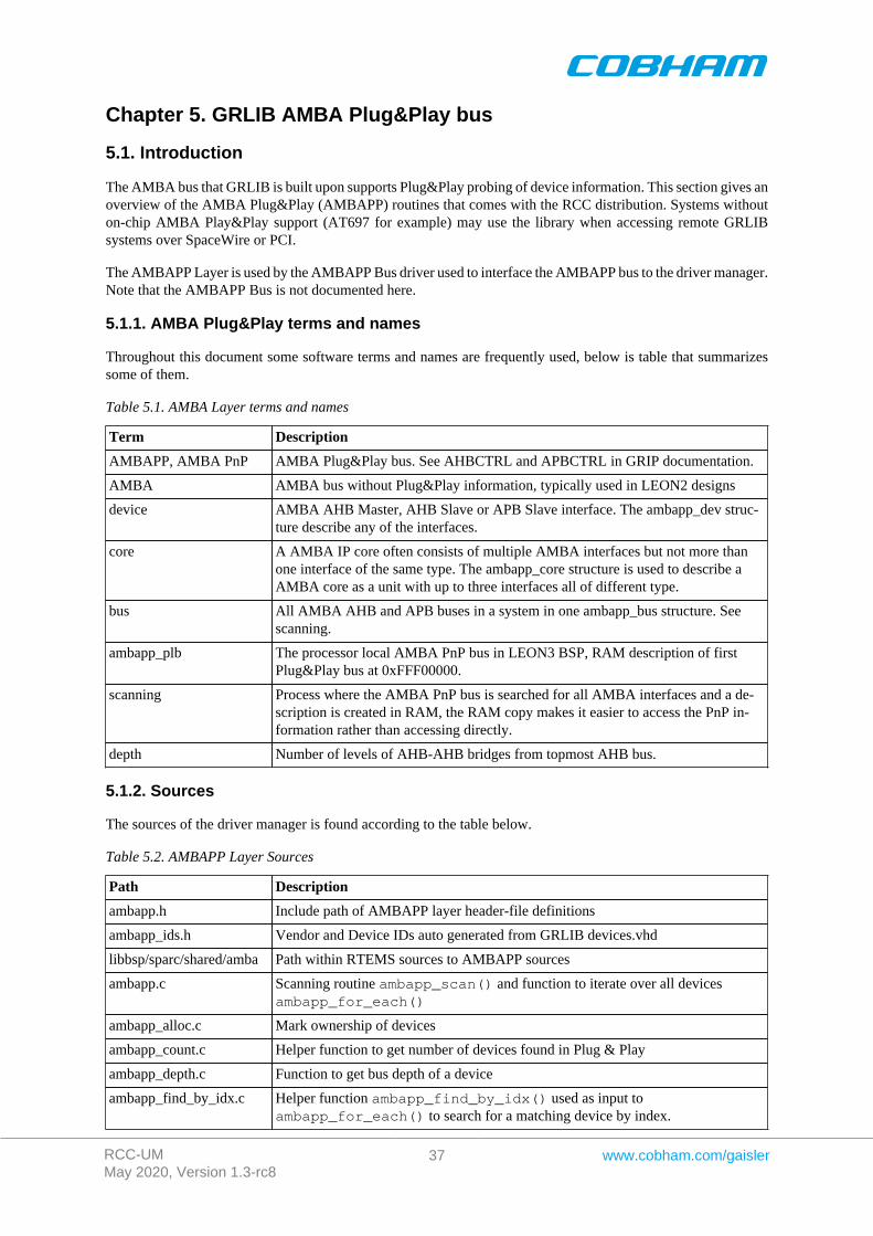
RCC-UMMay 2020, Version 1.3-rc8
37 www.cobham.com/gaisler
Chapter 5. GRLIB AMBA Plug&Play bus
5.1. Introduction
The AMBA bus that GRLIB is built upon supports Plug&Play probing of device information. This section gives anoverview of the AMBA Plug&Play (AMBAPP) routines that comes with the RCC distribution. Systems withouton-chip AMBA Play&Play support (AT697 for example) may use the library when accessing remote GRLIBsystems over SpaceWire or PCI.
The AMBAPP Layer is used by the AMBAPP Bus driver used to interface the AMBAPP bus to the driver manager.Note that the AMBAPP Bus is not documented here.
5.1.1. AMBA Plug&Play terms and names
Throughout this document some software terms and names are frequently used, below is table that summarizessome of them.
Table 5.1. AMBA Layer terms and names
Term Description
AMBAPP, AMBA PnP AMBA Plug&Play bus. See AHBCTRL and APBCTRL in GRIP documentation.
AMBA AMBA bus without Plug&Play information, typically used in LEON2 designs
device AMBA AHB Master, AHB Slave or APB Slave interface. The ambapp_dev struc-ture describe any of the interfaces.
core A AMBA IP core often consists of multiple AMBA interfaces but not more thanone interface of the same type. The ambapp_core structure is used to describe aAMBA core as a unit with up to three interfaces all of different type.
bus All AMBA AHB and APB buses in a system in one ambapp_bus structure. Seescanning.
ambapp_plb The processor local AMBA PnP bus in LEON3 BSP, RAM description of firstPlug&Play bus at 0xFFF00000.
scanning Process where the AMBA PnP bus is searched for all AMBA interfaces and a de-scription is created in RAM, the RAM copy makes it easier to access the PnP in-formation rather than accessing directly.
depth Number of levels of AHB-AHB bridges from topmost AHB bus.
5.1.2. Sources
The sources of the driver manager is found according to the table below.
Table 5.2. AMBAPP Layer Sources
Path Description
ambapp.h Include path of AMBAPP layer header-file definitions
ambapp_ids.h Vendor and Device IDs auto generated from GRLIB devices.vhd
libbsp/sparc/shared/amba Path within RTEMS sources to AMBAPP sources
ambapp.c Scanning routine ambapp_scan() and function to iterate over all devicesambapp_for_each()
ambapp_alloc.c Mark ownership of devices
ambapp_count.c Helper function to get number of devices found in Plug & Play
ambapp_depth.c Function to get bus depth of a device
ambapp_find_by_idx.c Helper function ambapp_find_by_idx() used as input toambapp_for_each() to search for a matching device by index.
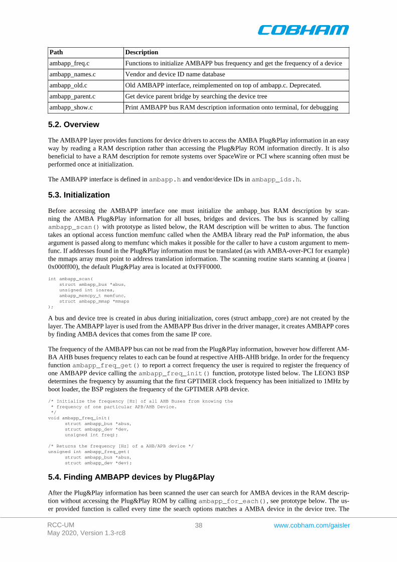
RCC-UMMay 2020, Version 1.3-rc8
38 www.cobham.com/gaisler
Path Description
ambapp_freq.c Functions to initialize AMBAPP bus frequency and get the frequency of a device
ambapp_names.c Vendor and device ID name database
ambapp_old.c Old AMBAPP interface, reimplemented on top of ambapp.c. Deprecated.
ambapp_parent.c Get device parent bridge by searching the device tree
ambapp_show.c Print AMBAPP bus RAM description information onto terminal, for debugging
5.2. Overview
The AMBAPP layer provides functions for device drivers to access the AMBA Plug&Play information in an easyway by reading a RAM description rather than accessing the Plug&Play ROM information directly. It is alsobeneficial to have a RAM description for remote systems over SpaceWire or PCI where scanning often must beperformed once at initialization.
The AMBAPP interface is defined in ambapp.h and vendor/device IDs in ambapp_ids.h.
5.3. Initialization
Before accessing the AMBAPP interface one must initialize the ambapp_bus RAM description by scan-ning the AMBA Plug&Play information for all buses, bridges and devices. The bus is scanned by callingambapp_scan() with prototype as listed below, the RAM description will be written to abus. The functiontakes an optional access function memfunc called when the AMBA library read the PnP information, the abusargument is passed along to memfunc which makes it possible for the caller to have a custom argument to mem-func. If addresses found in the Plug&Play information must be translated (as with AMBA-over-PCI for example)the mmaps array must point to address translation information. The scanning routine starts scanning at (ioarea |0x000ff00), the default Plug&Play area is located at 0xFFF0000.
int ambapp_scan( struct ambapp_bus *abus, unsigned int ioarea, ambapp_memcpy_t memfunc, struct ambapp_mmap *mmaps);
A bus and device tree is created in abus during initialization, cores (struct ambapp_core) are not created by thelayer. The AMBAPP layer is used from the AMBAPP Bus driver in the driver manager, it creates AMBAPP coresby finding AMBA devices that comes from the same IP core.
The frequency of the AMBAPP bus can not be read from the Plug&Play information, however how different AM-BA AHB buses frequency relates to each can be found at respective AHB-AHB bridge. In order for the frequencyfunction ambapp_freq_get() to report a correct frequency the user is required to register the frequency ofone AMBAPP device calling the ambapp_freq_init() function, prototype listed below. The LEON3 BSPdetermines the frequency by assuming that the first GPTIMER clock frequency has been initialized to 1MHz byboot loader, the BSP registers the frequency of the GPTIMER APB device.
/* Initialize the frequency [Hz] of all AHB Buses from knowing the * frequency of one particular APB/AHB Device. */void ambapp_freq_init( struct ambapp_bus *abus, struct ambapp_dev *dev, unsigned int freq);
/* Returns the frequency [Hz] of a AHB/APB device */unsigned int ambapp_freq_get( struct ambapp_bus *abus, struct ambapp_dev *dev);
5.4. Finding AMBAPP devices by Plug&Play
After the Plug&Play information has been scanned the user can search for AMBA devices in the RAM descrip-tion without accessing the Plug&Play ROM by calling ambapp_for_each(), see prototype below. The us-er provided function is called every time the search options matches a AMBA device in the device tree. The
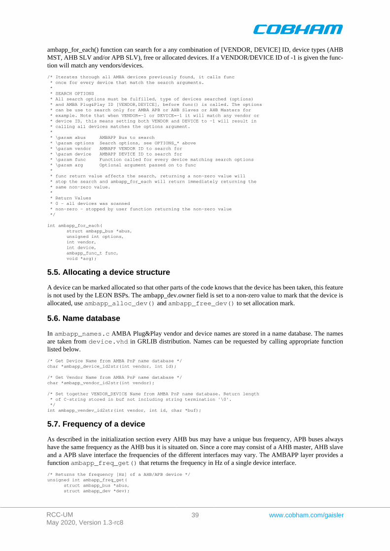
RCC-UMMay 2020, Version 1.3-rc8
39 www.cobham.com/gaisler
ambapp_for_each() function can search for a any combination of [VENDOR, DEVICE] ID, device types (AHBMST, AHB SLV and/or APB SLV), free or allocated devices. If a VENDOR/DEVICE ID of -1 is given the func-tion will match any vendors/devices.
/* Iterates through all AMBA devices previously found, it calls func * once for every device that match the search arguments. * * SEARCH OPTIONS * All search options must be fulfilled, type of devices searched (options) * and AMBA Plug&Play ID [VENDOR,DEVICE], before func() is called. The options * can be use to search only for AMBA APB or AHB Slaves or AHB Masters for * example. Note that when VENDOR=-1 or DEVICE=-1 it will match any vendor or * device ID, this means setting both VENDOR and DEVICE to -1 will result in * calling all devices matches the options argument. * * \param abus AMBAPP Bus to search * \param options Search options, see OPTIONS_* above * \param vendor AMBAPP VENDOR ID to search for * \param device AMBAPP DEVICE ID to search for * \param func Function called for every device matching search options * \param arg Optional argument passed on to func * * func return value affects the search, returning a non-zero value will * stop the search and ambapp_for_each will return immediately returning the * same non-zero value. * * Return Values * 0 - all devices was scanned * non-zero - stopped by user function returning the non-zero value */
int ambapp_for_each( struct ambapp_bus *abus, unsigned int options, int vendor, int device, ambapp_func_t func, void *arg);
5.5. Allocating a device structure
A device can be marked allocated so that other parts of the code knows that the device has been taken, this featureis not used by the LEON BSPs. The ambapp_dev.owner field is set to a non-zero value to mark that the device isallocated, use ambapp_alloc_dev() and ambapp_free_dev() to set allocation mark.
5.6. Name database
In ambapp_names.c AMBA Plug&Play vendor and device names are stored in a name database. The namesare taken from device.vhd in GRLIB distribution. Names can be requested by calling appropriate functionlisted below.
/* Get Device Name from AMBA PnP name database */char *ambapp_device_id2str(int vendor, int id);
/* Get Vendor Name from AMBA PnP name database */char *ambapp_vendor_id2str(int vendor);
/* Set together VENDOR_DEVICE Name from AMBA PnP name database. Return length * of C-string stored in buf not including string termination '\0'. */int ambapp_vendev_id2str(int vendor, int id, char *buf);
5.7. Frequency of a device
As described in the initialization section every AHB bus may have a unique bus frequency, APB buses alwayshave the same frequency as the AHB bus it is situated on. Since a core may consist of a AHB master, AHB slaveand a APB slave interface the frequencies of the different interfaces may vary. The AMBAPP layer provides afunction ambapp_freq_get() that returns the frequency in Hz of a single device interface.
/* Returns the frequency [Hz] of a AHB/APB device */unsigned int ambapp_freq_get( struct ambapp_bus *abus, struct ambapp_dev *dev);

RCC-UMMay 2020, Version 1.3-rc8
40 www.cobham.com/gaisler
Chapter 6. Driver Manager
6.1. Introduction
This section describes the Driver Manager available in RCC-1.3 distribution. The sources are located in cpuk-it/libdrvmgr in the RTEMS source release. The driver manager is used to simplify the handling of buses,devices, bus drivers, device driver, configuration of device instances and providing a common programming in-terface where possible for drivers regardless of bus architecture.
6.1.1. Driver manager terms and names
Throughout this document some terms and names are frequently used, below is table that summarizes some ofthem.
Table 6.1. Driver Manager terms and names
Term Description
Bus Describes a bus with child devices.
Device Describes a hardware device situated on a bus, bus driver.
Bridge device A device with a child bus.
Bus drives Software that handles a bus, implements the bus.
Device driver Software that handles hardware devices.
Root device Topmost device in driver manager tree, has no parent bus.
Root bus Topmost bus, the root device exports, has no parent bus.
Register bus Process where the driver manager is informed about the existence of a new bus.
Register device Process where the driver manager is informed about the existence of a new device.
Register driver Before driver manager initialization, drivers are added into a internal driver list.
Unite device and driver Process where the driver manager finds a device driver for a device.
Separate device anddriver
Process where a device driver is requested to never use the device any more, for ex-ample before a device is removed.
Unregister bus or de-vice
Inform driver manager about that a bus or device (and all child buses/devices) shouldbe removed from the device tree and related drivers be informed.
Init level The device driver and bus driver initialization process is performed in multiple stages,called initialization levels.
6.1.2. Sources
The sources of the driver manager is found according to the table below.
Table 6.2. Driver Manager Sources
Path Description
cpukit/libdrvmgr Path within RTEMS sources. Driver manager sources
drvmgr/drvmgr.h Include path of driver manager definitions
drvmgr/drvmgr_confdefs.h Include patch of driver configuration
6.2. Overview
The driver manager works with the concepts bus, bus driver, device, device driver and driver resources. Sinceeverything is tied together somehow it is quite difficult to start describing the driver manager, instead each com-ponent is described in a separate section below and the following text assumes that the reader has knowledge ofrespective component.
The driver manager manages all buses and devices in a system by using a tree structure. The root of the tree startswith the root device created by the root bus driver. The root device creates a bus which is called the root bus, it
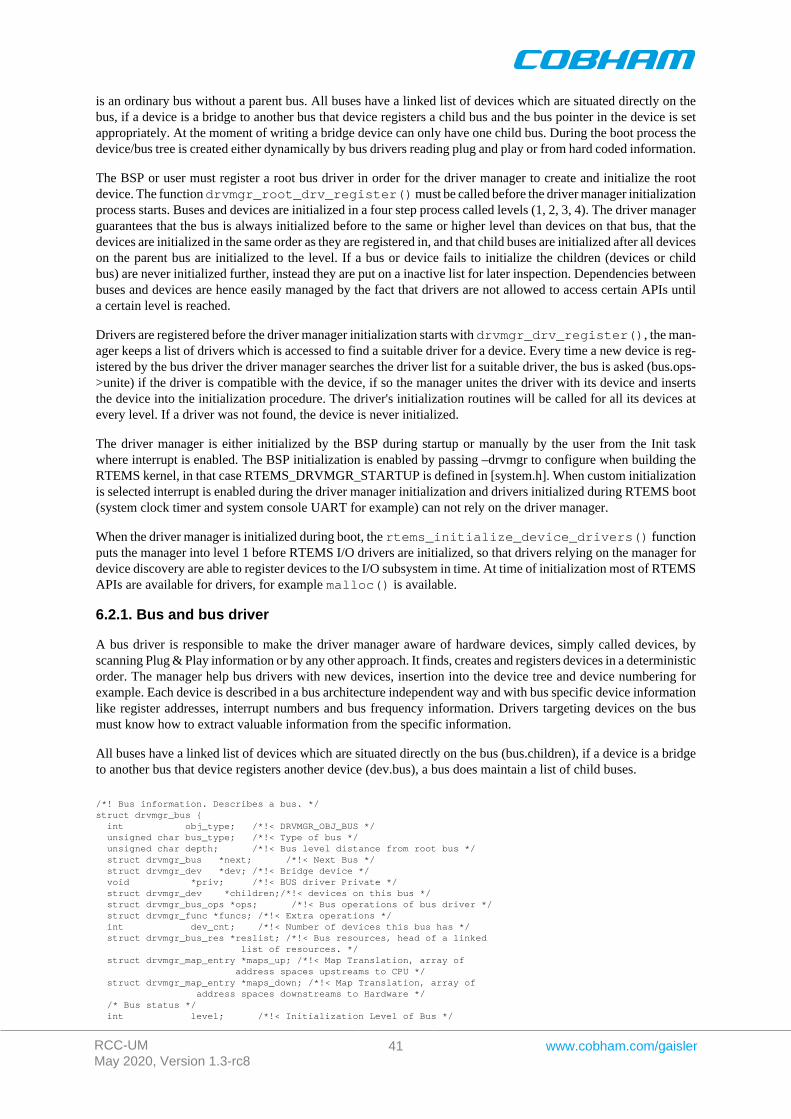
RCC-UMMay 2020, Version 1.3-rc8
41 www.cobham.com/gaisler
is an ordinary bus without a parent bus. All buses have a linked list of devices which are situated directly on thebus, if a device is a bridge to another bus that device registers a child bus and the bus pointer in the device is setappropriately. At the moment of writing a bridge device can only have one child bus. During the boot process thedevice/bus tree is created either dynamically by bus drivers reading plug and play or from hard coded information.
The BSP or user must register a root bus driver in order for the driver manager to create and initialize the rootdevice. The function drvmgr_root_drv_register() must be called before the driver manager initializationprocess starts. Buses and devices are initialized in a four step process called levels (1, 2, 3, 4). The driver managerguarantees that the bus is always initialized before to the same or higher level than devices on that bus, that thedevices are initialized in the same order as they are registered in, and that child buses are initialized after all deviceson the parent bus are initialized to the level. If a bus or device fails to initialize the children (devices or childbus) are never initialized further, instead they are put on a inactive list for later inspection. Dependencies betweenbuses and devices are hence easily managed by the fact that drivers are not allowed to access certain APIs untila certain level is reached.
Drivers are registered before the driver manager initialization starts with drvmgr_drv_register(), the man-ager keeps a list of drivers which is accessed to find a suitable driver for a device. Every time a new device is reg-istered by the bus driver the driver manager searches the driver list for a suitable driver, the bus is asked (bus.ops->unite) if the driver is compatible with the device, if so the manager unites the driver with its device and insertsthe device into the initialization procedure. The driver's initialization routines will be called for all its devices atevery level. If a driver was not found, the device is never initialized.
The driver manager is either initialized by the BSP during startup or manually by the user from the Init taskwhere interrupt is enabled. The BSP initialization is enabled by passing –drvmgr to configure when building theRTEMS kernel, in that case RTEMS_DRVMGR_STARTUP is defined in [system.h]. When custom initializationis selected interrupt is enabled during the driver manager initialization and drivers initialized during RTEMS boot(system clock timer and system console UART for example) can not rely on the driver manager.
When the driver manager is initialized during boot, the rtems_initialize_device_drivers() functionputs the manager into level 1 before RTEMS I/O drivers are initialized, so that drivers relying on the manager fordevice discovery are able to register devices to the I/O subsystem in time. At time of initialization most of RTEMSAPIs are available for drivers, for example malloc() is available.
6.2.1. Bus and bus driver
A bus driver is responsible to make the driver manager aware of hardware devices, simply called devices, byscanning Plug & Play information or by any other approach. It finds, creates and registers devices in a deterministicorder. The manager help bus drivers with new devices, insertion into the device tree and device numbering forexample. Each device is described in a bus architecture independent way and with bus specific device informationlike register addresses, interrupt numbers and bus frequency information. Drivers targeting devices on the busmust know how to extract valuable information from the specific information.
All buses have a linked list of devices which are situated directly on the bus (bus.children), if a device is a bridgeto another bus that device registers another device (dev.bus), a bus does maintain a list of child buses.
/*! Bus information. Describes a bus. */struct drvmgr_bus { int obj_type; /*!< DRVMGR_OBJ_BUS */ unsigned char bus_type; /*!< Type of bus */ unsigned char depth; /*!< Bus level distance from root bus */ struct drvmgr_bus *next; /*!< Next Bus */ struct drvmgr_dev *dev; /*!< Bridge device */ void *priv; /*!< BUS driver Private */ struct drvmgr_dev *children;/*!< devices on this bus */ struct drvmgr_bus_ops *ops; /*!< Bus operations of bus driver */ struct drvmgr_func *funcs; /*!< Extra operations */ int dev_cnt; /*!< Number of devices this bus has */ struct drvmgr_bus_res *reslist; /*!< Bus resources, head of a linked list of resources. */ struct drvmgr_map_entry *maps_up; /*!< Map Translation, array of address spaces upstreams to CPU */ struct drvmgr_map_entry *maps_down; /*!< Map Translation, array of address spaces downstreams to Hardware */ /* Bus status */ int level; /*!< Initialization Level of Bus */
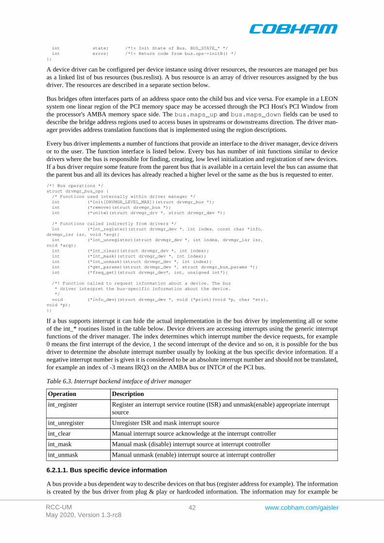
RCC-UMMay 2020, Version 1.3-rc8
42 www.cobham.com/gaisler
int state; /*!< Init State of Bus, BUS_STATE_* */ int error; /*!< Return code from bus.ops->initN() */};
A device driver can be configured per device instance using driver resources, the resources are managed per busas a linked list of bus resources (bus.reslist). A bus resource is an array of driver resources assigned by the busdriver. The resources are described in a separate section below.
Bus bridges often interfaces parts of an address space onto the child bus and vice versa. For example in a LEONsystem one linear region of the PCI memory space may be accessed through the PCI Host's PCI Window fromthe processor's AMBA memory space side. The bus.maps_up and bus.maps_down fields can be used todescribe the bridge address regions used to access buses in upstreams or downstreams direction. The driver man-ager provides address translation functions that is implemented using the region descriptions.
Every bus driver implements a number of functions that provide an interface to the driver manager, device driversor to the user. The function interface is listed below. Every bus has number of init functions similar to devicedrivers where the bus is responsible for finding, creating, low level initialization and registration of new devices.If a bus driver require some feature from the parent bus that is available in a certain level the bus can assume thatthe parent bus and all its devices has already reached a higher level or the same as the bus is requested to enter.
/*! Bus operations */struct drvmgr_bus_ops { /* Functions used internally within driver manager */ int (*init[DRVMGR_LEVEL_MAX])(struct drvmgr_bus *); int (*remove)(struct drvmgr_bus *); int (*unite)(struct drvmgr_drv *, struct drvmgr_dev *);
/* Functions called indirectly from drivers */ int (*int_register)(struct drvmgr_dev *, int index, const char *info,drvmgr_isr isr, void *arg); int (*int_unregister)(struct drvmgr_dev *, int index, drvmgr_isr isr,void *arg); int (*int_clear)(struct drvmgr_dev *, int index); int (*int_mask)(struct drvmgr_dev *, int index); int (*int_unmask)(struct drvmgr_dev *, int index); int (*get_params)(struct drvmgr_dev *, struct drvmgr_bus_params *); int (*freq_get)(struct drvmgr_dev*, int, unsigned int*);
/*! Function called to request information about a device. The bus * driver interpret the bus-specific information about the device. */ void (*info_dev)(struct drvmgr_dev *, void (*print)(void *p, char *str),void *p);};
If a bus supports interrupt it can hide the actual implementation in the bus driver by implementing all or someof the int_* routines listed in the table below. Device drivers are accessing interrupts using the generic interruptfunctions of the driver manager. The index determines which interrupt number the device requests, for example0 means the first interrupt of the device, 1 the second interrupt of the device and so on, it is possible for the busdriver to determine the absolute interrupt number usually by looking at the bus specific device information. If anegative interrupt number is given it is considered to be an absolute interrupt number and should not be translated,for example an index of -3 means IRQ3 on the AMBA bus or INTC# of the PCI bus.
Table 6.3. Interrupt backend inteface of driver manager
Operation Description
int_register Register an interrupt service routine (ISR) and unmask(enable) appropriate interruptsource
int_unregister Unregister ISR and mask interrupt source
int_clear Manual interrupt source acknowledge at the interrupt controller
int_mask Manual mask (disable) interrupt source at interrupt controller
int_unmask Manual unmask (enable) interrupt source at interrupt controller
6.2.1.1. Bus specific device information
A bus provide a bus dependent way to describe devices on that bus (register address for example). The informationis created by the bus driver from plug & play or hardcoded information. The information may for example be
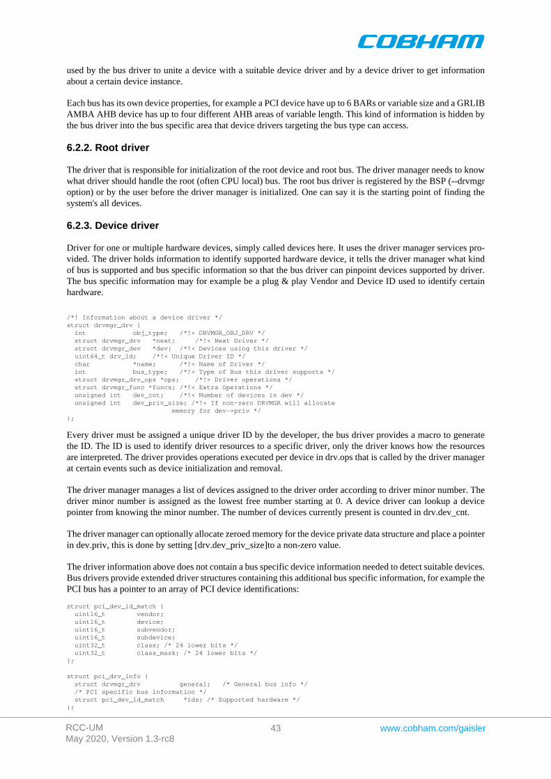
RCC-UMMay 2020, Version 1.3-rc8
43 www.cobham.com/gaisler
used by the bus driver to unite a device with a suitable device driver and by a device driver to get informationabout a certain device instance.
Each bus has its own device properties, for example a PCI device have up to 6 BARs or variable size and a GRLIBAMBA AHB device has up to four different AHB areas of variable length. This kind of information is hidden bythe bus driver into the bus specific area that device drivers targeting the bus type can access.
6.2.2. Root driver
The driver that is responsible for initialization of the root device and root bus. The driver manager needs to knowwhat driver should handle the root (often CPU local) bus. The root bus driver is registered by the BSP (--drvmgroption) or by the user before the driver manager is initialized. One can say it is the starting point of finding thesystem's all devices.
6.2.3. Device driver
Driver for one or multiple hardware devices, simply called devices here. It uses the driver manager services pro-vided. The driver holds information to identify supported hardware device, it tells the driver manager what kindof bus is supported and bus specific information so that the bus driver can pinpoint devices supported by driver.The bus specific information may for example be a plug & play Vendor and Device ID used to identify certainhardware.
/*! Information about a device driver */struct drvmgr_drv { int obj_type; /*!< DRVMGR_OBJ_DRV */ struct drvmgr_drv *next; /*!< Next Driver */ struct drvmgr_dev *dev; /*!< Devices using this driver */ uint64_t drv_id; /*!< Unique Driver ID */ char *name; /*!< Name of Driver */ int bus_type; /*!< Type of Bus this driver supports */ struct drvmgr_drv_ops *ops; /*!< Driver operations */ struct drvmgr_func *funcs; /*!< Extra Operations */ unsigned int dev_cnt; /*!< Number of devices in dev */ unsigned int dev_priv_size; /*!< If non-zero DRVMGR will allocate memory for dev->priv */};
Every driver must be assigned a unique driver ID by the developer, the bus driver provides a macro to generatethe ID. The ID is used to identify driver resources to a specific driver, only the driver knows how the resourcesare interpreted. The driver provides operations executed per device in drv.ops that is called by the driver managerat certain events such as device initialization and removal.
The driver manager manages a list of devices assigned to the driver order according to driver minor number. Thedriver minor number is assigned as the lowest free number starting at 0. A device driver can lookup a devicepointer from knowing the minor number. The number of devices currently present is counted in drv.dev_cnt.
The driver manager can optionally allocate zeroed memory for the device private data structure and place a pointerin dev.priv, this is done by setting [drv.dev_priv_size]to a non-zero value.
The driver information above does not contain a bus specific device information needed to detect suitable devices.Bus drivers provide extended driver structures containing this additional bus specific information, for example thePCI bus has a pointer to an array of PCI device identifications:
struct pci_dev_id_match { uint16_t vendor; uint16_t device; uint16_t subvendor; uint16_t subdevice; uint32_t class; /* 24 lower bits */ uint32_t class_mask; /* 24 lower bits */};
struct pci_drv_info { struct drvmgr_drv general; /* General bus info */ /* PCI specific bus information */ struct pci_dev_id_match *ids; /* Supported hardware */};
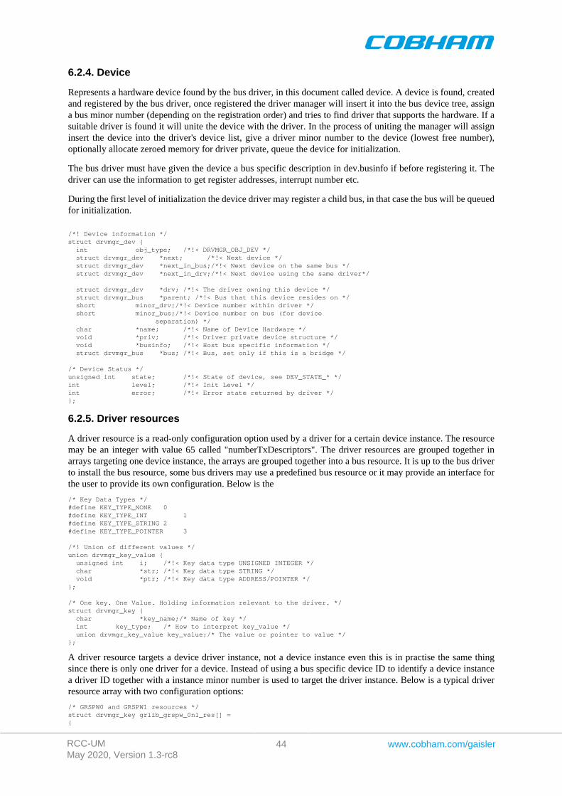
RCC-UMMay 2020, Version 1.3-rc8
44 www.cobham.com/gaisler
6.2.4. Device
Represents a hardware device found by the bus driver, in this document called device. A device is found, createdand registered by the bus driver, once registered the driver manager will insert it into the bus device tree, assigna bus minor number (depending on the registration order) and tries to find driver that supports the hardware. If asuitable driver is found it will unite the device with the driver. In the process of uniting the manager will assigninsert the device into the driver's device list, give a driver minor number to the device (lowest free number),optionally allocate zeroed memory for driver private, queue the device for initialization.
The bus driver must have given the device a bus specific description in dev.businfo if before registering it. Thedriver can use the information to get register addresses, interrupt number etc.
During the first level of initialization the device driver may register a child bus, in that case the bus will be queuedfor initialization.
/*! Device information */struct drvmgr_dev { int obj_type; /*!< DRVMGR_OBJ_DEV */ struct drvmgr_dev *next; /*!< Next device */ struct drvmgr_dev *next_in_bus;/*!< Next device on the same bus */ struct drvmgr_dev *next_in_drv;/*!< Next device using the same driver*/
struct drvmgr_drv *drv; /*!< The driver owning this device */ struct drvmgr_bus *parent; /*!< Bus that this device resides on */ short minor_drv;/*!< Device number within driver */ short minor_bus;/*!< Device number on bus (for device separation) */ char *name; /*!< Name of Device Hardware */ void *priv; /*!< Driver private device structure */ void *businfo; /*!< Host bus specific information */ struct drvmgr_bus *bus; /*!< Bus, set only if this is a bridge */
/* Device Status */unsigned int state; /*!< State of device, see DEV_STATE_* */int level; /*!< Init Level */int error; /*!< Error state returned by driver */};
6.2.5. Driver resources
A driver resource is a read-only configuration option used by a driver for a certain device instance. The resourcemay be an integer with value 65 called "numberTxDescriptors". The driver resources are grouped together inarrays targeting one device instance, the arrays are grouped together into a bus resource. It is up to the bus driverto install the bus resource, some bus drivers may use a predefined bus resource or it may provide an interface forthe user to provide its own configuration. Below is the
/* Key Data Types */#define KEY_TYPE_NONE 0#define KEY_TYPE_INT 1#define KEY_TYPE_STRING 2#define KEY_TYPE_POINTER 3
/*! Union of different values */union drvmgr_key_value { unsigned int i; /*!< Key data type UNSIGNED INTEGER */ char *str; /*!< Key data type STRING */ void *ptr; /*!< Key data type ADDRESS/POINTER */};
/* One key. One Value. Holding information relevant to the driver. */struct drvmgr_key { char *key_name;/* Name of key */ int key_type; /* How to interpret key_value */ union drvmgr_key_value key_value;/* The value or pointer to value */};
A driver resource targets a device driver instance, not a device instance even this is in practise the same thingsince there is only one driver for a device. Instead of using a bus specific device ID to identify a device instancea driver ID together with a instance minor number is used to target the driver instance. Below is a typical driverresource array with two configuration options:
/* GRSPW0 and GRSPW1 resources */struct drvmgr_key grlib_grspw_0n1_res[] ={
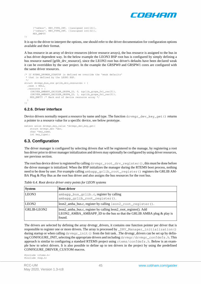
RCC-UMMay 2020, Version 1.3-rc8
45 www.cobham.com/gaisler
{"txDesc", KEY_TYPE_INT, {(unsigned int)16}}, {"rxDesc", KEY_TYPE_INT, {(unsigned int)32}}, KEY_EMPTY};
It is up to the driver to interpret the options, one should refer to the driver documentation for configuration optionsavailable and their format.
A bus resource in an array of device resources (driver resource arrays), the bus resource is assigned to the bus ina bus driver dependent way. In the below example the LEON3 BSP root bus is configured by simply defining abus resource named [grlib_drv_resource], since the LEON3 root bus driver's defaults have been declared weakit can be overridden by the user project. In the example the GRSPW0 and GRSPW1 cores are configured withthe same driver resources.
/* If RTEMS_DRVMGR_STARTUP is defined we override the "weak defaults" * that is defined by the LEON3 BSP. */struct drvmgr_bus_res grlib_drv_resources = { .next = NULL, .resource = { {DRIVER_AMBAPP_GAISLER_GRSPW_ID, 0, &grlib_grspw_0n1_res[0]}, {DRIVER_AMBAPP_GAISLER_GRSPW_ID, 1, &grlib_grspw_0n1_res[0]}, RES_EMPTY /* Mark end of device resource array */ }};
6.2.6. Driver interface
Device drivers normally request a resource by name and type. The function drvmgr_dev_key_get() returnsa pointer to a resource value for a specific device, see below prototype.
extern union drvmgr_key_value *drvmgr_dev_key_get( struct drvmgr_dev *dev, char *key_name, int key_type);
6.3. Configuration
The driver manager is configured by selecting drivers that will be registered to the manage, by registering a rootbus driver prior to driver manager initialization and drivers may optionally be configured by using driver resources,see previous section.
The root bus device driver is registered by calling drvmgr_root_drv_register(), this must be done beforethe driver manager is initialized. When the BSP initializes the manager during the RTEMS boot process, nothingneed to be done by user. For example calling ambapp_grlib_root_register() registers the GRLIB AM-BA Plug & Play Bus as the root bus driver and also assigns the bus resources for the root bus.
Table 6.4. Root device driver entry points for LEON systems
System Root driver
LEON3 ambapp_bus_grlib.c, register by callingambapp_grlib_root_register().
LEON2 leon2_amba_bus.c, register by calling leon2_root_register().
GRLIB-LEON2 leon2_amba_bus.c, register by calling leon2_root_register(). AddLEON2_AMBA_AMBAPP_ID to the bus so that the GRLIB AMBA plug & play isfound.
The drivers are selected by defining the array drvmgr_drivers, it contains one function pointer per driver that isresponsible to register one or more drivers. The array is processed by _DRV_Manager_initialization()during startup or when calling drvmgr_init() from the Init task. .The drvmgr_drivers can be set up by defin-ing CONFIGURE_INIT, selecting the appropriate drivers and including drvmgr/drvmgr_confdefs.h. Thisapproach is similar to configuring a standard RTEMS project using rtems/confdefs.h. Below is an exam-ple how to select drivers. It is also possible to define up to ten drivers in the project by using the predefinedCONFIGURE_DRIVER_CUSTOM macros.
#include <rtems.h>#include <bsp.h>
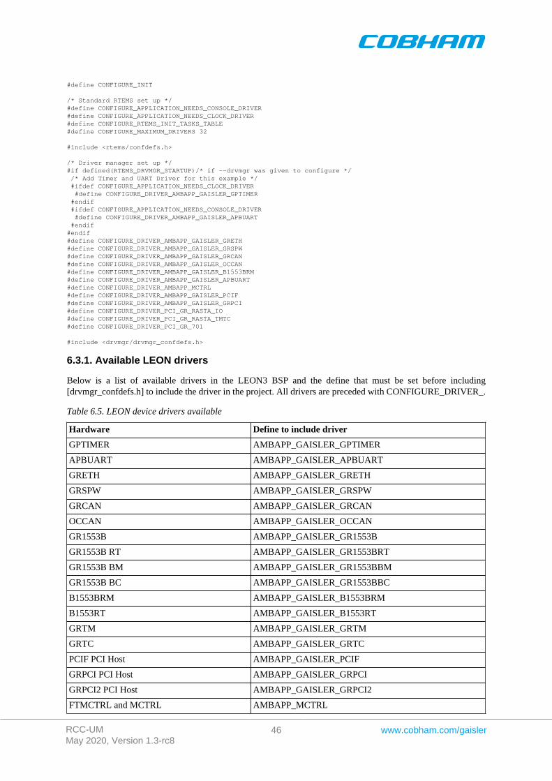
RCC-UMMay 2020, Version 1.3-rc8
46 www.cobham.com/gaisler
#define CONFIGURE_INIT
/* Standard RTEMS set up */#define CONFIGURE_APPLICATION_NEEDS_CONSOLE_DRIVER#define CONFIGURE_APPLICATION_NEEDS_CLOCK_DRIVER#define CONFIGURE_RTEMS_INIT_TASKS_TABLE#define CONFIGURE_MAXIMUM_DRIVERS 32
#include <rtems/confdefs.h>
/* Driver manager set up */#if defined(RTEMS_DRVMGR_STARTUP)/* if --drvmgr was given to configure */ /* Add Timer and UART Driver for this example */ #ifdef CONFIGURE_APPLICATION_NEEDS_CLOCK_DRIVER #define CONFIGURE_DRIVER_AMBAPP_GAISLER_GPTIMER #endif #ifdef CONFIGURE_APPLICATION_NEEDS_CONSOLE_DRIVER #define CONFIGURE_DRIVER_AMBAPP_GAISLER_APBUART #endif#endif#define CONFIGURE_DRIVER_AMBAPP_GAISLER_GRETH#define CONFIGURE_DRIVER_AMBAPP_GAISLER_GRSPW#define CONFIGURE_DRIVER_AMBAPP_GAISLER_GRCAN#define CONFIGURE_DRIVER_AMBAPP_GAISLER_OCCAN#define CONFIGURE_DRIVER_AMBAPP_GAISLER_B1553BRM#define CONFIGURE_DRIVER_AMBAPP_GAISLER_APBUART#define CONFIGURE_DRIVER_AMBAPP_MCTRL#define CONFIGURE_DRIVER_AMBAPP_GAISLER_PCIF#define CONFIGURE_DRIVER_AMBAPP_GAISLER_GRPCI#define CONFIGURE_DRIVER_PCI_GR_RASTA_IO#define CONFIGURE_DRIVER_PCI_GR_RASTA_TMTC#define CONFIGURE_DRIVER_PCI_GR_701
#include <drvmgr/drvmgr_confdefs.h>
6.3.1. Available LEON drivers
Below is a list of available drivers in the LEON3 BSP and the define that must be set before including[drvmgr_confdefs.h] to include the driver in the project. All drivers are preceded with CONFIGURE_DRIVER_.
Table 6.5. LEON device drivers available
Hardware Define to include driver
GPTIMER AMBAPP_GAISLER_GPTIMER
APBUART AMBAPP_GAISLER_APBUART
GRETH AMBAPP_GAISLER_GRETH
GRSPW AMBAPP_GAISLER_GRSPW
GRCAN AMBAPP_GAISLER_GRCAN
OCCAN AMBAPP_GAISLER_OCCAN
GR1553B AMBAPP_GAISLER_GR1553B
GR1553B RT AMBAPP_GAISLER_GR1553BRT
GR1553B BM AMBAPP_GAISLER_GR1553BBM
GR1553B BC AMBAPP_GAISLER_GR1553BBC
B1553BRM AMBAPP_GAISLER_B1553BRM
B1553RT AMBAPP_GAISLER_B1553RT
GRTM AMBAPP_GAISLER_GRTM
GRTC AMBAPP_GAISLER_GRTC
PCIF PCI Host AMBAPP_GAISLER_PCIF
GRPCI PCI Host AMBAPP_GAISLER_GRPCI
GRPCI2 PCI Host AMBAPP_GAISLER_GRPCI2
FTMCTRL and MCTRL AMBAPP_MCTRL
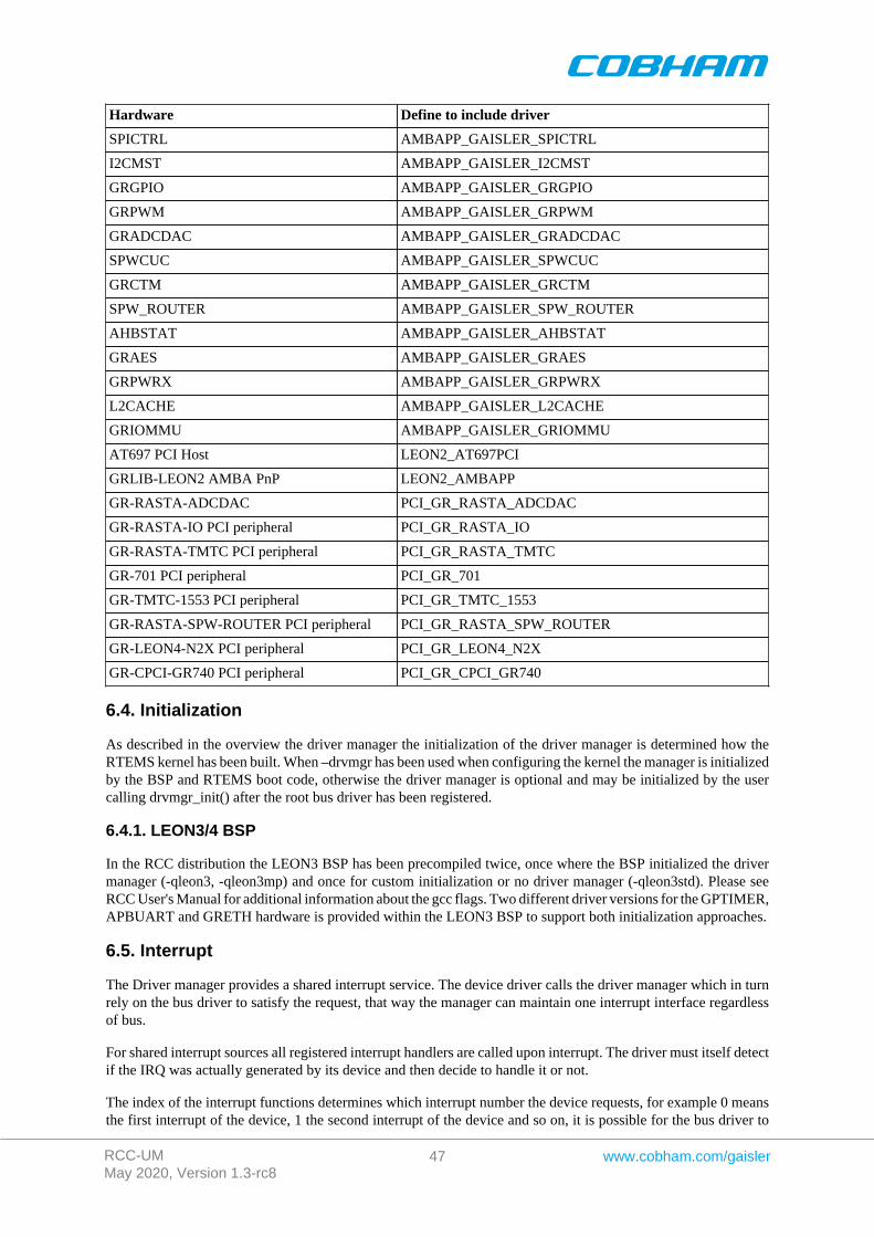
RCC-UMMay 2020, Version 1.3-rc8
47 www.cobham.com/gaisler
Hardware Define to include driver
SPICTRL AMBAPP_GAISLER_SPICTRL
I2CMST AMBAPP_GAISLER_I2CMST
GRGPIO AMBAPP_GAISLER_GRGPIO
GRPWM AMBAPP_GAISLER_GRPWM
GRADCDAC AMBAPP_GAISLER_GRADCDAC
SPWCUC AMBAPP_GAISLER_SPWCUC
GRCTM AMBAPP_GAISLER_GRCTM
SPW_ROUTER AMBAPP_GAISLER_SPW_ROUTER
AHBSTAT AMBAPP_GAISLER_AHBSTAT
GRAES AMBAPP_GAISLER_GRAES
GRPWRX AMBAPP_GAISLER_GRPWRX
L2CACHE AMBAPP_GAISLER_L2CACHE
GRIOMMU AMBAPP_GAISLER_GRIOMMU
AT697 PCI Host LEON2_AT697PCI
GRLIB-LEON2 AMBA PnP LEON2_AMBAPP
GR-RASTA-ADCDAC PCI_GR_RASTA_ADCDAC
GR-RASTA-IO PCI peripheral PCI_GR_RASTA_IO
GR-RASTA-TMTC PCI peripheral PCI_GR_RASTA_TMTC
GR-701 PCI peripheral PCI_GR_701
GR-TMTC-1553 PCI peripheral PCI_GR_TMTC_1553
GR-RASTA-SPW-ROUTER PCI peripheral PCI_GR_RASTA_SPW_ROUTER
GR-LEON4-N2X PCI peripheral PCI_GR_LEON4_N2X
GR-CPCI-GR740 PCI peripheral PCI_GR_CPCI_GR740
6.4. Initialization
As described in the overview the driver manager the initialization of the driver manager is determined how theRTEMS kernel has been built. When –drvmgr has been used when configuring the kernel the manager is initializedby the BSP and RTEMS boot code, otherwise the driver manager is optional and may be initialized by the usercalling drvmgr_init() after the root bus driver has been registered.
6.4.1. LEON3/4 BSP
In the RCC distribution the LEON3 BSP has been precompiled twice, once where the BSP initialized the drivermanager (-qleon3, -qleon3mp) and once for custom initialization or no driver manager (-qleon3std). Please seeRCC User's Manual for additional information about the gcc flags. Two different driver versions for the GPTIMER,APBUART and GRETH hardware is provided within the LEON3 BSP to support both initialization approaches.
6.5. Interrupt
The Driver manager provides a shared interrupt service. The device driver calls the driver manager which in turnrely on the bus driver to satisfy the request, that way the manager can maintain one interrupt interface regardlessof bus.
For shared interrupt sources all registered interrupt handlers are called upon interrupt. The driver must itself detectif the IRQ was actually generated by its device and then decide to handle it or not.
The index of the interrupt functions determines which interrupt number the device requests, for example 0 meansthe first interrupt of the device, 1 the second interrupt of the device and so on, it is possible for the bus driver to
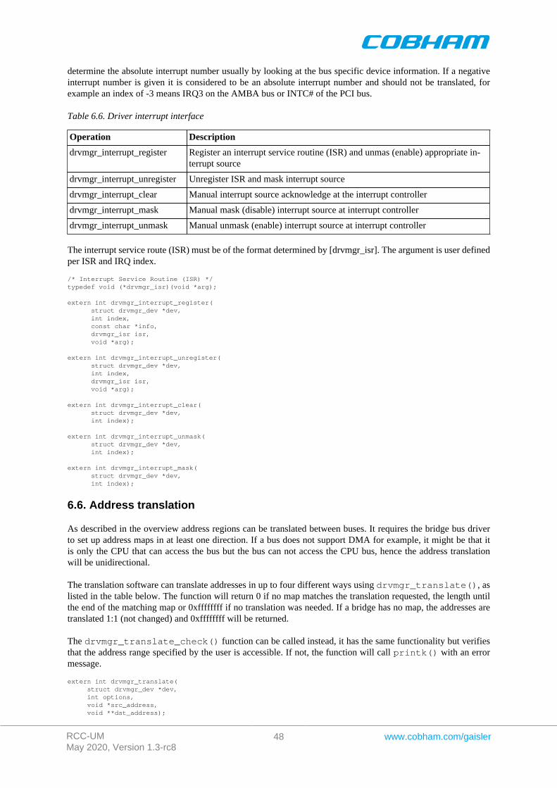
RCC-UMMay 2020, Version 1.3-rc8
48 www.cobham.com/gaisler
determine the absolute interrupt number usually by looking at the bus specific device information. If a negativeinterrupt number is given it is considered to be an absolute interrupt number and should not be translated, forexample an index of -3 means IRQ3 on the AMBA bus or INTC# of the PCI bus.
Table 6.6. Driver interrupt interface
Operation Description
drvmgr_interrupt_register Register an interrupt service routine (ISR) and unmas (enable) appropriate in-terrupt source
drvmgr_interrupt_unregister Unregister ISR and mask interrupt source
drvmgr_interrupt_clear Manual interrupt source acknowledge at the interrupt controller
drvmgr_interrupt_mask Manual mask (disable) interrupt source at interrupt controller
drvmgr_interrupt_unmask Manual unmask (enable) interrupt source at interrupt controller
The interrupt service route (ISR) must be of the format determined by [drvmgr_isr]. The argument is user definedper ISR and IRQ index.
/* Interrupt Service Routine (ISR) */typedef void (*drvmgr_isr)(void *arg);
extern int drvmgr_interrupt_register( struct drvmgr_dev *dev, int index, const char *info, drvmgr_isr isr, void *arg);
extern int drvmgr_interrupt_unregister( struct drvmgr_dev *dev, int index, drvmgr_isr isr, void *arg);
extern int drvmgr_interrupt_clear( struct drvmgr_dev *dev, int index);
extern int drvmgr_interrupt_unmask( struct drvmgr_dev *dev, int index);
extern int drvmgr_interrupt_mask( struct drvmgr_dev *dev, int index);
6.6. Address translation
As described in the overview address regions can be translated between buses. It requires the bridge bus driverto set up address maps in at least one direction. If a bus does not support DMA for example, it might be that itis only the CPU that can access the bus but the bus can not access the CPU bus, hence the address translationwill be unidirectional.
The translation software can translate addresses in up to four different ways using drvmgr_translate(), aslisted in the table below. The function will return 0 if no map matches the translation requested, the length untilthe end of the matching map or 0xffffffff if no translation was needed. If a bridge has no map, the addresses aretranslated 1:1 (not changed) and 0xffffffff will be returned.
The drvmgr_translate_check() function can be called instead, it has the same functionality but verifiesthat the address range specified by the user is accessible. If not, the function will call printk() with an errormessage.
extern int drvmgr_translate( struct drvmgr_dev *dev, int options, void *src_address, void **dst_address);
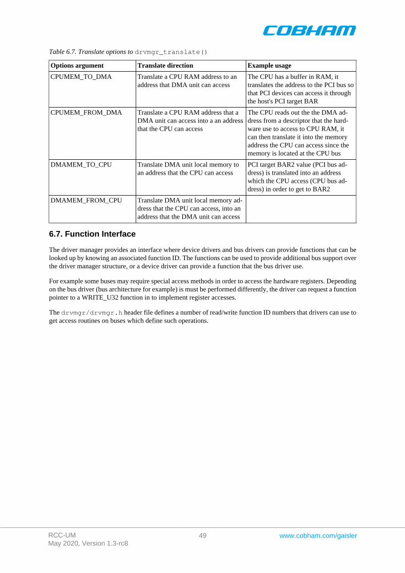
RCC-UMMay 2020, Version 1.3-rc8
49 www.cobham.com/gaisler
Table 6.7. Translate options to drvmgr_translate()
Options argument Translate direction Example usage
CPUMEM_TO_DMA Translate a CPU RAM address to anaddress that DMA unit can access
The CPU has a buffer in RAM, ittranslates the address to the PCI bus sothat PCI devices can access it throughthe host's PCI target BAR
CPUMEM_FROM_DMA Translate a CPU RAM address that aDMA unit can access into a an addressthat the CPU can access
The CPU reads out the the DMA ad-dress from a descriptor that the hard-ware use to access to CPU RAM, itcan then translate it into the memoryaddress the CPU can access since thememory is located at the CPU bus
DMAMEM_TO_CPU Translate DMA unit local memory toan address that the CPU can access
PCI target BAR2 value (PCI bus ad-dress) is translated into an addresswhich the CPU access (CPU bus ad-dress) in order to get to BAR2
DMAMEM_FROM_CPU Translate DMA unit local memory ad-dress that the CPU can access, into anaddress that the DMA unit can access
6.7. Function Interface
The driver manager provides an interface where device drivers and bus drivers can provide functions that can belooked up by knowing an associated function ID. The functions can be used to provide additional bus support overthe driver manager structure, or a device driver can provide a function that the bus driver use.
For example some buses may require special access methods in order to access the hardware registers. Dependingon the bus driver (bus architecture for example) is must be performed differently, the driver can request a functionpointer to a WRITE_U32 function in to implement register accesses.
The drvmgr/drvmgr.h header file defines a number of read/write function ID numbers that drivers can use toget access routines on buses which define such operations.
RCC-UMMay 2020, Version 1.3-rc8
50 www.cobham.com/gaisler
Chapter 7. RMAP Stack
7.1. Introduction
This section describes the RMAP stack function interface available for RTEMS. The RMAP stack provide a simpleinterface that can generate RMAP commands and transmit them over SpaceWire by relying on the RMAP stackdriver layer. Read, read-modify-write and write with acknowledge or verification will block the caller until thetransaction is completed. The features of the RMAP stack is summarized below:
• header and data CRC generation, if not generated by hardware• logical addressing• path addressing• generate all read and write types defined by the RMAP specification.• thread safe if requested• driver layer to support multiple SpaceWire hardware• driver for GRSPW driver• zero-copy API
The two interfaces the RMAP stack implements can be found in the rmap header file (rmap.h), it contains def-initions of all necessary data structures, bit masks, procedures and functions used when accessing the functioninterface.
This document describes the user interface, but not the driver interface.
7.1.1. Examples
The SpaceWire bus driver can be seen as an example, it can be found under rtems-4.10/c/src/lib/libb-sp/sparc/shared/drvmgr/spw_bus.c.
7.2. Driver Interface
The driver interface is not described in this document.
7.3. Logical and Path addressing
The RMAP stack is by default configured to do logical addressing, however a custom callback function may beused to implement path addressing. The stack will call the function twice (one for distination path and one forreturn path) when the RMAP header is generated, the function is responsible to write the address path bytes directlyinto the header at the specified location.
7.4. Zero-copy implementation
The RMAP stack is zero-copy meaning that the data of the transfer is not copied, this improves performance. Notethat when the RMAP driver does not support CRC generation the RMAP stack will write the data CRC after theinput data, this means that the caller is responsible to reserve one byte of space when writing data. The RMAPstack will not write the data CRC after the data in cases where the RMAP driver that support CRC generation.
Note that even though the RMAP stack is zero-copy the RMAP driver may not be zero-copy, lowering the per-formance.
To get true zero-copy from user to SpaceWire transfer one can instead use the asynchonous RMAP layer part ofthe RMAP stack and interface that to the GRSPW Packet Driver.
7.5. RMAP GRSPW driver
A driver for the RTEMS GRSPW driver is provided with the RMAP stack, the driver automatically check if theGRSPW hardware has support for CRC generation.
The GRSPW driver is named rmap_drv_grspw.c.
RCC-UMMay 2020, Version 1.3-rc8
51 www.cobham.com/gaisler
7.6. Thread-safe
The RMAP stack can be configured to be thread safe, when entering the stack an internal semaphore will beobtained guaranteeing that multiple threads of execution can enter simultaneously. It is not needed when only onetask is using the RMAP stack or if the RMAP driver itself is thread-safe.
A task may be blocked waiting for another task to complete the RMAP operation, when the RMAP stack isconfigured thread-safe.
7.7. User interface
The location of the RMAP stack is indicated in Table 7.1. All paths are given relative the RTEMS kernel sourceroot.
Table 7.1. RMAP stack source location
Source description Location
Interface implementation c/src/lib/libbsp/sparc/shared/spw/rmap.c
Interface declaration c/src/lib/libbsp/sparc/shared/include/rmap.h
7.7.1. Data structures
The [rmap_config] data structure is used to configure the RMAP stack, as an argument to rmap_init(). Thedata structure is defined in rmap.h.
typedef int (*rmap_route_t)( void *cookie, int dir, int srcadr, int dstadr, void *buf, int *len );
struct rmap_config { rmap_route_t route_func; int tid_msb; int spw_adr; struct rmap_drv *drv; int max_rx_len; int max_tx_len; int thread_safe;}
Table 7.2. rmap_config members
Member Description
route_func Function is a callback, called when the RMAP stack is about to generate the addressingto the target node address. It can be used to implement path addressing. Set the functionpointer to NULL to make the stack use logical addressing.
tid_msb Control the eight most significant bits in the TID field in the RMAP header. Set to -1for normal operation, the RMAP stack will use all bits in TID for sequence counting.This option can be used when multiple RMAP stacks or other parts of the software sendsRMAP commands but not using the RMAP stack. This requires, of course, a thread-safeRMAP driver.
spw_adr The SpW Address of the SpW interface used.
drv RMAP driver used for transmission.
max_rx_len Maximum data length of received packets, this must match the RMAP driver's configura-tion.
max_tx_len Maximum data length of transmitted packets, this must match the RMAP driver's configu-ration.
RCC-UMMay 2020, Version 1.3-rc8
52 www.cobham.com/gaisler
Member Description
thread_safe Set this to non-zero to enable the RMAP stack to create a semaphore used to protect theRMAP stack and the RMAP driver from multiple tasks entering the transfer function(s) ofthe stack at the same time.
A RMAP command is described the rmap_command structure, the type decide which parts of the union data isused when generating the RMAP header. In order to simplify for the caller three data structures avoiding theunion are provided, they are named rmap_command_write, rmap_command_read, rmap_command_rmw.They can be used instead of rmap_command as argument to the function interface.
struct rmap_command { char type; unsigned char dstadr; unsigned char dstkey; unsigned char status; unsigned short tid; unsigned long long address; union { struct { unsigned int length; unsigned char *data; } write; struct { unsigned int length; unsigned int datalength; unsigned int *data; } read; struct { unsigned int length; unsigned int data; unsigned int mask; unsigned int oldlength; unsigned int olddata; } read_m_write; } data;}
Table 7.3. rmap_command members
Member Description
type Type of RMAP transfer, Read/Write/Read-Modify-Write/Acked Write etc., seeRMAP_CMD_*.
dstadr Destination address of SpaceWire Node that the RMAP command should be execute upon.
dstkey SpaceWire destination key of target node
status Output from stack: Error/Status response. Zero if no response is successful
tid Output from stack: TID assigned to packet header
address 40-bit address that the operation targets
data A union of different input and output arguements depending on the type of command.
7.7.2. Function interface description
The table below sumarize all available functions in the RMAP stack.
Table 7.4. RMAP stack function prototypes
Prototype Name
void *rmap_init(struct rmap_config *config)
int rmap_ioctl(void *cookie, int command, void *arg)
int rmap_send(void *cookie, struct rmap_command *cmd)
int rmap_write(void *cookie, void *dst, void *buf , int length, int dstadr, int dstkey)
int rmap_read(void *cookie, void *src, void *buf , int length, int dstadr, int dstkey)
RCC-UMMay 2020, Version 1.3-rc8
53 www.cobham.com/gaisler
Prototype Name
unsigned char rmap_crc_calc(unsigned char *data , unsigned int len)
7.7.2.1. rmap_init
The RMAP stack must be initialized before other function may be called. Calling rmap_init initializes the RMAPstack. During the initialization the RMAP stack is configured as described by the rmap_config data structure,see the data structures section.
If successful, rmap_init will return a non-zero value later used as input argument (cookie) in other RMAP stackfunctions. The cookie is needed in order to support multiple RMAP stacks in parallel, the cookie identify a certainstack.
If the RMAP stack fail to initialize zero is returned.
The rmap_config structure is described in Section 7.7.1.
7.7.2.2. rmap_ioctl
Set run-time options such as blocking, time out, get configuration and operating the stack such as starting andstopping the communication link.
This function is not thread-safe.
If successful zero is returned.
7.7.2.3. rmap_send
Execute a command by sending the command, then wait for the response if a response is expected. This functionwill block until the response is received or if the timeout is expired. The timeout functionality may not be supportedby the RMAP driver.
Note that when the RMAP stack is in non-blocking mode the stack will not wait for the response, however if theresponse is available the response is handled. If the response wasn't received -2 is returned.
Note that if the RMAP driver does not support CRC generation a byte will be written after the data provided bythe user, please see zero-copy section.
If an error occurs -1 is returned. On success 0 is returned. Note that even though the RMAP request failed theRMAP stack may return zero, the RMAP status indicates the error response of the target, see the rmap_commandstructure in the data structures section.
7.7.2.4. rmap_crc_calc
This function is a help function used by the RMAP stack to calculate the CRC of the header and data when CRCgeneration is not provided by the RMAP driver.
7.7.2.5. rmap_write and rmap_read
The read and write functions are example functions that implement the most common read and write operations.The function will call rmap_send to execute the read and write request.
RCC-UMMay 2020, Version 1.3-rc8
54 www.cobham.com/gaisler
Chapter 8. SpaceWire Network model
8.1. Introduction
This document describes the SpaceWire bus driver used to write device drivers for a SpaceWire Node accessedover SpaceWire with RMAP.
8.2. Overview
In order to provide a standardized way of writing drivers for Nodes on a SpaceWire network and to improve codereuse a Bus driver for a SpaceWire network as been written. The bus driver is written using the concepts of theDriver Manager.
The SpaceWire Bus driver provides services to the nodes in the network, some of the services are listed below:
• Read/Write access to target (using the RMAP protocol)• Interrupt handling• Per node resources
The hardware topology is organized by the driver manager's bus and device trees, the SpaceWire bus driver isattached to the SpaceWire core providing the actual SpaceWire interface in order to maintain the hardware topol-ogy. It is important that the on-chip devices and drivers are loaded and initialized before the SpaceWire networkas the SpaceWire network depends on the on-chip devices. The bus driver initialization is controlled and startedby the user after the driver manager has initialized the on-chip bus.
The SpaceWire driver requires the SpaceWire RMAP stack to perform read and write access to the SpaceWireTarget Nodes.
The driver support Logical SpaceWire Addressing only at this point.
8.3. Requirements
The SpaceWire network must be Logical addressed and the SpaceWire bus driver requires the RMAP stack fortarget node access.
8.4. Node Description
The SpaceWire bus driver is a driver for the devices on the SpaceWire bus, in this particular case a device is calleda SpaceWire Node, a node is described by the data structure spw_node. Each node has a Node ID, a name, and alist of optional keys. A SpaceWire node has the following configurable elements:
• Node ID (connected to driver)• Node Name• SpaceWire Destination key• SpaceWire Node Address• IRQ setup (up to four IRQs)
8.4.1. The Node ID
The Node ID identifies a type of target, not a certain Node. The Node ID in combination with the node index onthe bus creates a Unique identifier. The Node ID is used to identify a driver that can handle the node. The nodeindex is taken from the index in the Node table.
The NodeIDs are defined in spw_bus_ids.h.
8.5. Read and write operation
A SpaceWire target Node's memory and registers are accessed using RMAP commands. The RMAP protocol isimplemented by the RMAP stack in a separate module.
The driver manager provide read and write operations to registers and memory for drivers, the SpaceWire Busdriver implements them for the SpaceWire bus. A node driver calls the standard read and write operations which
RCC-UMMay 2020, Version 1.3-rc8
55 www.cobham.com/gaisler
are translated into a SpaceWire bus read/write which is implemented using the RMAP stack. All operations areblocking until data is available, the return value indicates it the transfer was successful or not.
8.6. Interrupt handling
The RMAP protocol does not support interrupt handling, this is instead implemented by an separate interruptline, the interrupt handling is an optional feature per SpaceWire node. Each SpaceWire node may have up to fourinterrupts connected to interrupt capable GPIO pins.
The user must setup a Virtual Interrupt Table, the table entries provide a way for the bus driver to translate aVirtual IRQ number to a GPIO pin. The GPIO pin is used to connect to the IRQ and receive the interrupt. In thenode description a node may for example define it's IRQ1 to be connected to the SpaceWire bus Virtual IRQ 2,which in turn is connected to GPIO5.
Setting up and controlling interrupts for node drivers are similar to a on-chip device driver, however the interruptservice routine must take more things in to account. The ISR is expected to read and write to the node's registersover the SpaceWire bus, that would require that SpaceWire bus is not busy and that the SpaceWire request isexecuted very fast, non of these assumptions can be made. The ISR can thus not execute in interrupt context,instead a high priority ISR task is managed by the SpaceWire bus driver. This way the ISR can access the nodeover SpaceWire, however extra care must be taken in the node driver to avoid conflicts and races when the ISRis executing as a task, instead of locking interrupt as in tradition drivers one may use a semaphore to protect thecritical regions.
8.7. Using the spacewire bus driver
The SpaceWire bus is registered to the driver manager for each SpaceWire network by calling thespw_bus_register() function with a configuration description. The configuration describe the nodes on thenetwork, IRQ setup, driver resources
The SpaceWire bus is attached to a on-chip GRSPW driver, the core that provides access to the SpaceWire busvia the RMAP stack.
There is an example of how to configure and use the SpaceWire bus driver in config_spw_bus.c.
SpaceWire Node drivers must set the bus type to DRVMGR_BUS_TYPE_SPW_RMAP and define an array withall devices nodes that are supported by the driver. The AMBA PnP RMAP may be considered as an examplenode driver.
RCC-UMMay 2020, Version 1.3-rc8
56 www.cobham.com/gaisler
Chapter 9. AMBA over SpaceWire
9.1. Introduction
This document describes the AMBA Plug&Play bus driver used to write device drivers for AMBA cores accessedover SpaceWire. The driver rely on the SpaceWire network bus driver.
9.2. Overview
The AMBA Plug&Play bus driver for the SpaceWire network is a generic driver for all GRLIB systems by usingthe Plug&Play functionality provided by GRLIB systems. The address of the Plug&Play area start address isconfigurable. The driver is a driver for a SpaceWire Node on a SpaceWire Network.
The system is accessed using RMAP commands and interrupt handling is performed when the IRQMP core isfound.
The services provided to device drivers on the AMBA bus accessed over SpaceWire are listed below:
• AMBA Plug&Play scanning over SpaceWire• Interrupt management (driver for IRQMP)• Read and Write registers and memory over SpaceWire• Memory allocating (ambapp_rmap_partition_memalign())• Driver resources
9.3. Requirements
The SpaceWire bus driver is required.
9.4. Interrupt handling
See the interrupt service routine of the AMBA Plug&Play bus is executed on the SpaceWire bus driver's ISR task.See the SpaceWire Bus driver's documentation about the constraints of the interrupt handling.
9.5. Memory allocation on target
Two functions are provided by the AMBA RMAP driver to simplify memory allocation of target memory,ambapp_rmap_partition_create() and ambapp_rmap_partition_memalign().
A partition symbolize a memory area with certain properties. For example, partition 0 might be SRAM and parti-tion 1 might be on-chip RAM. A memory controller driver typically registers a partition after it has initialized thememory controller and perhaps washed the memory, other drivers may then request memory from a certain par-tition. The partition number that a driver request memory from may be configured from driver resources makingit possible for the user to easily control which parts of the memory is used. For example a descriptor table maybe required to be located in on-chip RAM.
Drivers request memory with memory alignment requirements by callingambapp_rmap_partition_memalign(). The device structure is passed along when creating partitions andwhen allocating memory, making it possible for the AMBA RMAP bus driver to allocate memory from the samebus.
9.6. Differences between on-chip AMBA drivers
There some differences when writing drivers for a remote target accessed over SpaceWire using the AMBA RMAPdriver, this section identifies the most common differences.
• Read and Write access (memory and registers) must be through functions rather than direct, functions areprovided
• Error handling of failed read/write accesses, this may also be handled on a global level (by the SpaceWirebus driver)
• Memory allocation of target memory

RCC-UMMay 2020, Version 1.3-rc8
57 www.cobham.com/gaisler
• ISR may block (executed in task context)• Lock out ISR method is different• Drivers must set bus type to DRVMGR_BUS_TYPE_AMBAPP_RMAP
RCC-UMMay 2020, Version 1.3-rc8
58 www.cobham.com/gaisler
Chapter 10. LEON PCI host bridge drivers
10.1. Introduction
This section describes PCI Host support in RTEMS for SPARC/LEON processors. The supported PCI Host hard-ware are listed below
• GRLIB GRPCI2• GRLIB GRPCI• GRLIB PCIF• AT697 PCI
The PCI drivers require the Driver Manager and PCI Library available in the RCC distribution. The PCI Librarydocumentation is available in the doc/user directory in the RCC kernel source distribution. Note that the PCILibrary is not available in the official RTEMS distribution.
The GRPCI2 core can support a DMA interface that has its own driver explained in Chapter 11.
10.1.1. Examples
There is a simple example available that initializes the PCI Bus, lists the PCI configuration and demonstrates howto write a PCI device driver. The example is part of the RCC distribution, it can be found under /opt/rtems-5/src/samples/rtems-pci.c. The rtems-shell.c sample found in the same directory also demonstratesPCI with RTEMS, note that there is a pci command which can be used to get information about the PCI set up.
10.2. Sources
The drivers can be found in the RTEMS SPARC BSP shared directory and in the LEON2 BSP. See table below.
Table 10.1. PCI driver source location
Location Description
.../libbsp/sparc/leon2/pci/at697_pci.c AT967 PCI
.../libbsp/sparc/shared/pci/grpci2.c GRPCI2
.../libbsp/sparc/shared/pci/grpci.c GRPCI
.../libbsp/sparc/shared/pci/pcif.c GRLIB PCIF, ACTEL PCI AMBA wrapper
cpukit/libpci PCI Library
cpukit/libpci/pci_bus.* PCI Bus driver for driver manager
doc/user/libpci.t PCI Library documentation
10.3. Configuration
The PCI interrupt assignment can be configured to override the Plug & Play information. The PCI driver is con-figured using any combination of the driver resources in the table below, see samples or driver manager documen-tation how driver resources are assigned.
Table 10.2. PCI Host driver parameter description
Name Type Parameter Description
INTA# INT Select system IRQ for PCI interrupt pin INTA#
INTB# INT Select system IRQ for PCI interrupt pin INTB#
INTC# INT Select system IRQ for PCI interrupt pin INTC#
INTD# INT Select system IRQ for PCI interrupt pin INTD#
10.3.1. GRPCI
GRLIB designs using the GRPCI PCI Host bridge has in addition to the INTX# configuration options the belowoptions.
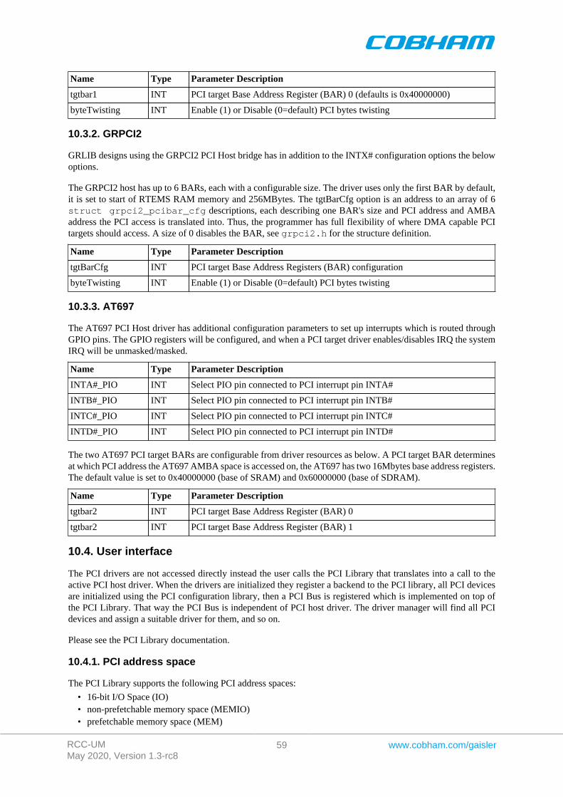
RCC-UMMay 2020, Version 1.3-rc8
59 www.cobham.com/gaisler
Name Type Parameter Description
tgtbar1 INT PCI target Base Address Register (BAR) 0 (defaults is 0x40000000)
byteTwisting INT Enable (1) or Disable (0=default) PCI bytes twisting
10.3.2. GRPCI2
GRLIB designs using the GRPCI2 PCI Host bridge has in addition to the INTX# configuration options the belowoptions.
The GRPCI2 host has up to 6 BARs, each with a configurable size. The driver uses only the first BAR by default,it is set to start of RTEMS RAM memory and 256MBytes. The tgtBarCfg option is an address to an array of 6struct grpci2_pcibar_cfg descriptions, each describing one BAR's size and PCI address and AMBAaddress the PCI access is translated into. Thus, the programmer has full flexibility of where DMA capable PCItargets should access. A size of 0 disables the BAR, see grpci2.h for the structure definition.
Name Type Parameter Description
tgtBarCfg INT PCI target Base Address Registers (BAR) configuration
byteTwisting INT Enable (1) or Disable (0=default) PCI bytes twisting
10.3.3. AT697
The AT697 PCI Host driver has additional configuration parameters to set up interrupts which is routed throughGPIO pins. The GPIO registers will be configured, and when a PCI target driver enables/disables IRQ the systemIRQ will be unmasked/masked.
Name Type Parameter Description
INTA#_PIO INT Select PIO pin connected to PCI interrupt pin INTA#
INTB#_PIO INT Select PIO pin connected to PCI interrupt pin INTB#
INTC#_PIO INT Select PIO pin connected to PCI interrupt pin INTC#
INTD#_PIO INT Select PIO pin connected to PCI interrupt pin INTD#
The two AT697 PCI target BARs are configurable from driver resources as below. A PCI target BAR determinesat which PCI address the AT697 AMBA space is accessed on, the AT697 has two 16Mbytes base address registers.The default value is set to 0x40000000 (base of SRAM) and 0x60000000 (base of SDRAM).
Name Type Parameter Description
tgtbar2 INT PCI target Base Address Register (BAR) 0
tgtbar2 INT PCI target Base Address Register (BAR) 1
10.4. User interface
The PCI drivers are not accessed directly instead the user calls the PCI Library that translates into a call to theactive PCI host driver. When the drivers are initialized they register a backend to the PCI library, all PCI devicesare initialized using the PCI configuration library, then a PCI Bus is registered which is implemented on top ofthe PCI Library. That way the PCI Bus is independent of PCI host driver. The driver manager will find all PCIdevices and assign a suitable driver for them, and so on.
Please see the PCI Library documentation.
10.4.1. PCI address space
The PCI Library supports the following PCI address spaces:
• 16-bit I/O Space (IO)• non-prefetchable memory space (MEMIO)• prefetchable memory space (MEM)

RCC-UMMay 2020, Version 1.3-rc8
60 www.cobham.com/gaisler
• configuration space (CFG)
On LEON hardware the address spaces are accessed over dedicated AHB areas as ordinary AMBA memory ac-cesses and it will be transformed into appropriate PCI access type depending on which AHB area (window) wasaccessed and of which AMBA access type (burst, single access). Note that LEON hardware have only one memorywindow which can do both MEM and MEMIO access types, so the PCI Library is configured with one MEMIOWindow. No special instructions are required to access I/O or configuration space. The location of the PCI Win-dows are determined by looking at AMBA plug and play information for the PCI Host core. The AT697 PCI MEMWindow is defined to 0xA0000000-0xF0000000.
The PCI Library is informed about the PCI windows location and size. PCI BARs are allocated within the MEM,MEMIO and I/O windows.
10.4.2. PCI interrupt
For every PCI target board found by the PCI Library the PCI driver is asked to provide a system IRQ for thetarget's PCI Interrupt pin number. The interrupt is normally taken from AMBA Plug & Play interrupt numberassigned to the PCI Host hardware itself. However it can be overridden using driver resources as described insection Section 10.4.
After the PCI Library has allocated memory for all targets BARs and assigned IRQ. The PCI bus driver can accessthe IRQ number from configuration space and connect a PCI Target driver with its system interrupt source. ThePCI target drivers use the Driver Manager interrupt register routine.
When a PCI target driver enable interrupt using the Driver Manager interrupt enable routine, the system IRQ for thePCI target is unmasked. AT697 PCI interrupt is not routed through the PCI core but through user selectable GPIO.Enabling IRQ will only cause the system IRQ to be unmasked, the PCI driver will not change GPIO parameters,this is required by the user to set up. PCI is level triggered.
PCI interrupts must be acknowledge after being handled to ensure that the interrupt handler is not executed twice.The Driver Manager interrupt clear routine can be used to clear the pending bit in the LEON interrupt controlledafter the interrupt has been handled by the PCI target Driver.
When the LEON takes the PCI IRQ the LEON IRQ controller is acknowledged, however the PCI target is stilldriving the IRQ line causing the LEON IRQ controller being set once again. This is because PCI is level triggered(level is still low), the other IRQs on the LEON is edge triggered. The solution is to acknowledge the LEON IRQcontroller after the PCI target has stop driving the PCI IRQ line, only then will the driver be able to stop the lastalready handled IRQ to occur. This must be done in the PCI ISR of the target device driver after the hardwarecausing the IRQ has been acknowledge.
10.4.3. PCI endianess
The PCI bus is defined little-endian whereas the SPARC and AMBA bus are defined big-endian, this imposes aproblem where the CPU has to byte-swap the data in PCI accesses. The GRPCI and GRPCI2 host controllers hassupport for doing byte-swapping in hardware for us,, it is enabled/disabled using the byteTwisting configurationoption. The AT697 PCI and PCIF does not have this option, the software defaults to the PCI bus being non-standard big-endian instead. Please see more information about this in hardware manuals and the PCI Librarydocumentation.
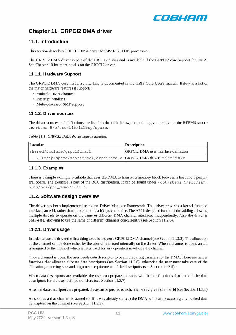
RCC-UMMay 2020, Version 1.3-rc8
61 www.cobham.com/gaisler
Chapter 11. GRPCI2 DMA driver
11.1. Introduction
This section describes GRPCI2 DMA driver for SPARC/LEON processors.
The GRPCI2 DMA driver is part of the GRPCI2 driver and is available if the GRPCI2 core support the DMA.See Chapter 10 for more details on the GRPCI2 driver.
11.1.1. Hardware Support
The GRPCI2 DMA core hardware interface is documented in the GRIP Core User's manual. Below is a list ofthe major hardware features it supports:
• Multiple DMA channels• Interrupt handling• Multi-processor SMP support
11.1.2. Driver sources
The driver sources and definitions are listed in the table below, the path is given relative to the RTEMS sourcetree rtems-5/c/src/lib/libbsp/sparc.
Table 11.1. GRPCI2 DMA driver source location
Location Description
shared/include/grpci2dma.h GRPCI2 DMA user interface definition
.../libbsp/sparc/shared/pci/grpci2dma.c GRPCI2 DMA driver implementation
11.1.3. Examples
There is a simple example available that uses the DMA to transfer a memory block between a host and a periph-eral board. The example is part of the RCC distribution, it can be found under /opt/rtems-5/src/sam-ples/pci/pci_demo/test.c.
11.2. Software design overview
The driver has been implemented using the Driver Manager Framework. The driver provides a kernel functioninterface, an API, rather than implementing a IO system device. The API is designed for multi-threadding allowingmultiple threads to operate on the same or different DMA channel interfaces independently. Also the driver isSMP-safe, allowing to use the same or different channels concurrently (see Section 11.2.6).
11.2.1. Driver usage
In order to use the driver the first thing to do is to open a GRPCI2 DMA channel (see Section 11.3.2). The allocationof the channel can be done either by the user or managed internally on the driver. When a channel is open, an idis assigned to the channel which is later used for any operation involving the channel.
Once a channel is open, the user needs data descriptor to begin preparing transfers for the DMA. There are helperfunctions that allow to allocate data descriptors (see Section 11.3.6), otherwise the user must take care of theallocation, repecting size and alignment requirements of the descriptors (see Section 11.2.5).
When data descriptors are available, the user can prepare transfers with helper functions that prepare the datadescriptors for the user-defined transfers (see Section 11.3.7).
After the data descriptors are prepared, these can be pushed to a channel with a given channel id (see Section 11.3.8)
As soon as a that channel is started (or if it was already started) the DMA will start processing any pushed datadescriptors on the channel (see Section 11.3.3).
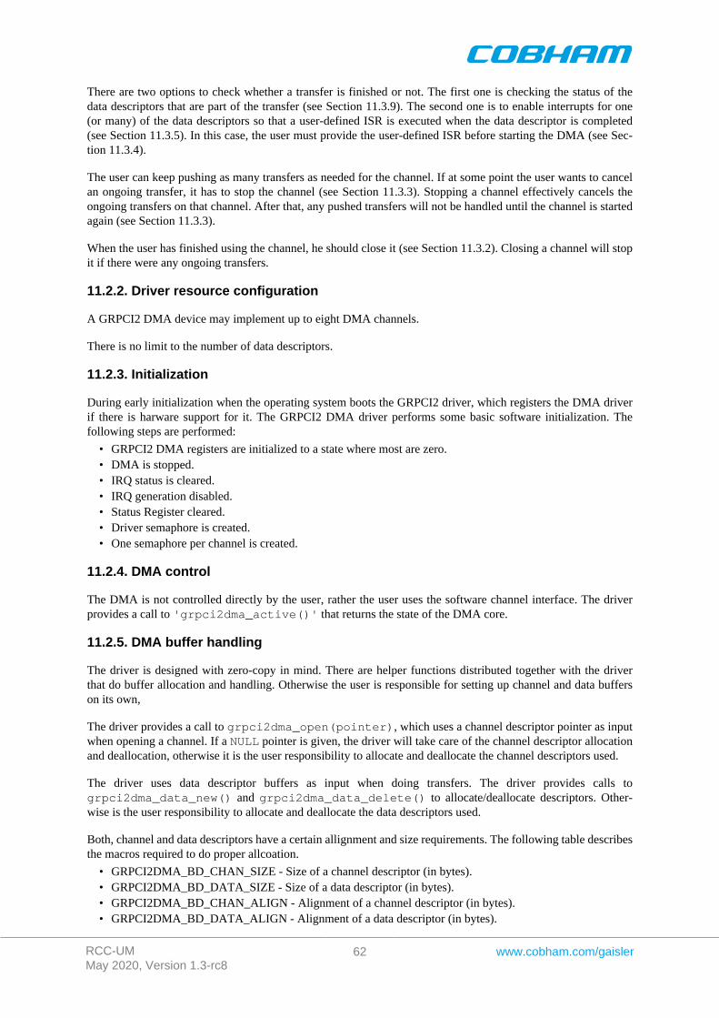
RCC-UMMay 2020, Version 1.3-rc8
62 www.cobham.com/gaisler
There are two options to check whether a transfer is finished or not. The first one is checking the status of thedata descriptors that are part of the transfer (see Section 11.3.9). The second one is to enable interrupts for one(or many) of the data descriptors so that a user-defined ISR is executed when the data descriptor is completed(see Section 11.3.5). In this case, the user must provide the user-defined ISR before starting the DMA (see Sec-tion 11.3.4).
The user can keep pushing as many transfers as needed for the channel. If at some point the user wants to cancelan ongoing transfer, it has to stop the channel (see Section 11.3.3). Stopping a channel effectively cancels theongoing transfers on that channel. After that, any pushed transfers will not be handled until the channel is startedagain (see Section 11.3.3).
When the user has finished using the channel, he should close it (see Section 11.3.2). Closing a channel will stopit if there were any ongoing transfers.
11.2.2. Driver resource configuration
A GRPCI2 DMA device may implement up to eight DMA channels.
There is no limit to the number of data descriptors.
11.2.3. Initialization
During early initialization when the operating system boots the GRPCI2 driver, which registers the DMA driverif there is harware support for it. The GRPCI2 DMA driver performs some basic software initialization. Thefollowing steps are performed:
• GRPCI2 DMA registers are initialized to a state where most are zero.• DMA is stopped.• IRQ status is cleared.• IRQ generation disabled.• Status Register cleared.• Driver semaphore is created.• One semaphore per channel is created.
11.2.4. DMA control
The DMA is not controlled directly by the user, rather the user uses the software channel interface. The driverprovides a call to 'grpci2dma_active()' that returns the state of the DMA core.
11.2.5. DMA buffer handling
The driver is designed with zero-copy in mind. There are helper functions distributed together with the driverthat do buffer allocation and handling. Otherwise the user is responsible for setting up channel and data bufferson its own,
The driver provides a call to grpci2dma_open(pointer), which uses a channel descriptor pointer as inputwhen opening a channel. If a NULL pointer is given, the driver will take care of the channel descriptor allocationand deallocation, otherwise it is the user responsibility to allocate and deallocate the channel descriptors used.
The driver uses data descriptor buffers as input when doing transfers. The driver provides calls togrpci2dma_data_new() and grpci2dma_data_delete() to allocate/deallocate descriptors. Other-wise is the user responsibility to allocate and deallocate the data descriptors used.
Both, channel and data descriptors have a certain allignment and size requirements. The following table describesthe macros required to do proper allcoation.
• GRPCI2DMA_BD_CHAN_SIZE - Size of a channel descriptor (in bytes).• GRPCI2DMA_BD_DATA_SIZE - Size of a data descriptor (in bytes).• GRPCI2DMA_BD_CHAN_ALIGN - Alignment of a channel descriptor (in bytes).• GRPCI2DMA_BD_DATA_ALIGN - Alignment of a data descriptor (in bytes).
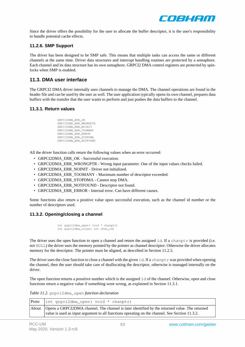
RCC-UMMay 2020, Version 1.3-rc8
63 www.cobham.com/gaisler
Since the driver offers the possibility for the user to allocate the buffer descriptor, it is the user's responsibilityto handle potential cache effects.
11.2.6. SMP Support
The driver has been designed to be SMP safe. This means that multiple tasks can access the same or differentchannels at the same time. Driver data structures and interrupt handling routines are protected by a semaphore.Each channel and its data structure has its own semaphore. GRPCI2 DMA control registers are protected by spin-locks when SMP is enabled.
11.3. DMA user interface
The GRPCI2 DMA driver internally uses channels to manage the DMA. The channel operations are found in theheader file and can be used by the user as well. The user application typically opens its own channel, prepares databuffers with the transfer that the user wants to perform and just pushes the data buffers to the channel.
11.3.1. Return values
GRPCI2DMA_ERR_OK GRPCI2DMA_ERR_WRONGPTR GRPCI2DMA_ERR_NOINIT GRPCI2DMA_ERR_TOOMANY GRPCI2DMA_ERR_ERROR GRPCI2DMA_ERR_STOPDMA GRPCI2DMA_ERR_NOTFOUND
All the driver function calls return the following values when an error occurred:
• GRPCI2DMA_ERR_OK - Successful execution.• GRPCI2DMA_ERR_WRONGPTR - Wrong input parameter. One of the input values checks failed.• GRPCI2DMA_ERR_NOINIT - Driver not initialized.• GRPCI2DMA_ERR_TOOMANY - Maximum number of descriptor exceeded.• GRPCI2DMA_ERR_STOPDMA - Cannot stop DMA.• GRPCI2DMA_ERR_NOTFOUND - Descriptor not found.• GRPCI2DMA_ERR_ERROR - Internal error. Can have different causes.
Some functions also return a positive value upon successful execution, such as the channel id number or thenumber of descriptors used.
11.3.2. Opening/closing a channel
int grpci2dma_open( void * chanptr) int grpci2dma_close( int chan_id)
The driver uses the open function to open a channel and return the assigned id. If a chanptr is provided (i.e.not NULL) the driver uses the memory pointed by the pointer as channel descriptor. Otherwise the driver allocatesmemory for the descriptor. The pointer must be aligned, as described in Section 11.2.5.
The driver uses the close function to close a channel with the given id. If a chanptr was provided when openingthe channel, then the user should take care of deallocating the descriptor, otherwise is managed internally on thedriver.
The open function returns a possitive number which is the assigned id of the channel. Otherwise, open and closefunctions return a negative value if something went wrong, as explained in Section 11.3.1.
Table 11.2. grpci2dma_open function declaration
Proto int grpci2dma_open( void * chanptr)
About Opens a GRPCI2DMA channel. The channel is later identified by the returned value. The returnedvalue is used as input argument to all functions operating on the channel. See Section 11.3.2.
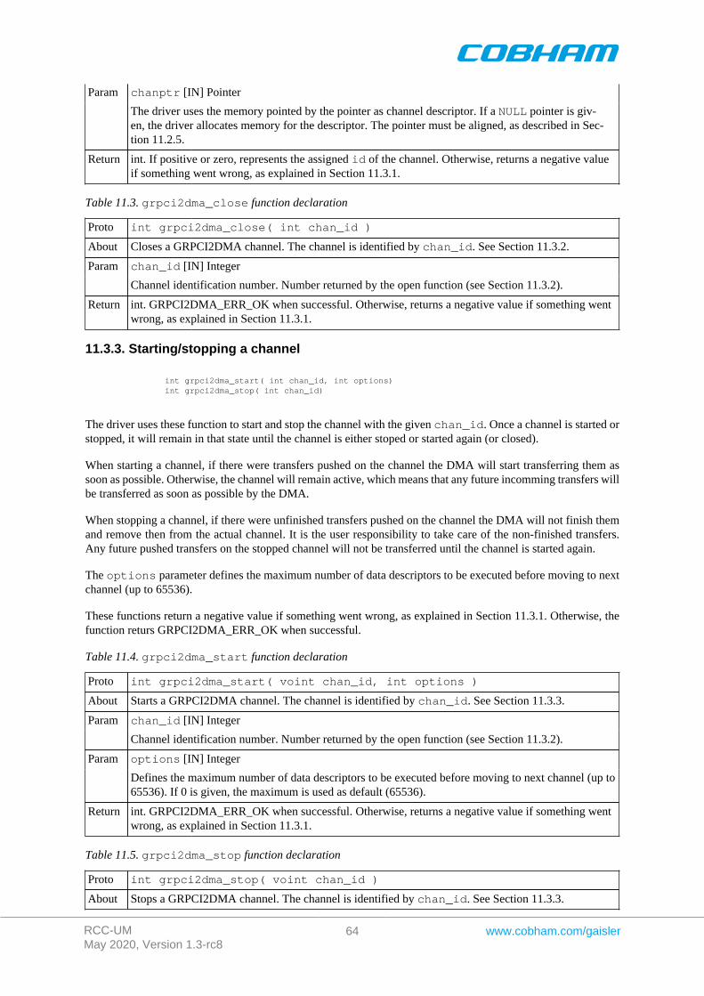
RCC-UMMay 2020, Version 1.3-rc8
64 www.cobham.com/gaisler
chanptr [IN] PointerParam
The driver uses the memory pointed by the pointer as channel descriptor. If a NULL pointer is giv-en, the driver allocates memory for the descriptor. The pointer must be aligned, as described in Sec-tion 11.2.5.
Return int. If positive or zero, represents the assigned id of the channel. Otherwise, returns a negative valueif something went wrong, as explained in Section 11.3.1.
Table 11.3. grpci2dma_close function declaration
Proto int grpci2dma_close( int chan_id )
About Closes a GRPCI2DMA channel. The channel is identified by chan_id. See Section 11.3.2.
chan_id [IN] IntegerParam
Channel identification number. Number returned by the open function (see Section 11.3.2).
Return int. GRPCI2DMA_ERR_OK when successful. Otherwise, returns a negative value if something wentwrong, as explained in Section 11.3.1.
11.3.3. Starting/stopping a channel
int grpci2dma_start( int chan_id, int options) int grpci2dma_stop( int chan_id)
The driver uses these function to start and stop the channel with the given chan_id. Once a channel is started orstopped, it will remain in that state until the channel is either stoped or started again (or closed).
When starting a channel, if there were transfers pushed on the channel the DMA will start transferring them assoon as possible. Otherwise, the channel will remain active, which means that any future incomming transfers willbe transferred as soon as possible by the DMA.
When stopping a channel, if there were unfinished transfers pushed on the channel the DMA will not finish themand remove then from the actual channel. It is the user responsibility to take care of the non-finished transfers.Any future pushed transfers on the stopped channel will not be transferred until the channel is started again.
The options parameter defines the maximum number of data descriptors to be executed before moving to nextchannel (up to 65536).
These functions return a negative value if something went wrong, as explained in Section 11.3.1. Otherwise, thefunction returs GRPCI2DMA_ERR_OK when successful.
Table 11.4. grpci2dma_start function declaration
Proto int grpci2dma_start( voint chan_id, int options )
About Starts a GRPCI2DMA channel. The channel is identified by chan_id. See Section 11.3.3.
chan_id [IN] IntegerParam
Channel identification number. Number returned by the open function (see Section 11.3.2).
options [IN] IntegerParam
Defines the maximum number of data descriptors to be executed before moving to next channel (up to65536). If 0 is given, the maximum is used as default (65536).
Return int. GRPCI2DMA_ERR_OK when successful. Otherwise, returns a negative value if something wentwrong, as explained in Section 11.3.1.
Table 11.5. grpci2dma_stop function declaration
Proto int grpci2dma_stop( voint chan_id )
About Stops a GRPCI2DMA channel. The channel is identified by chan_id. See Section 11.3.3.
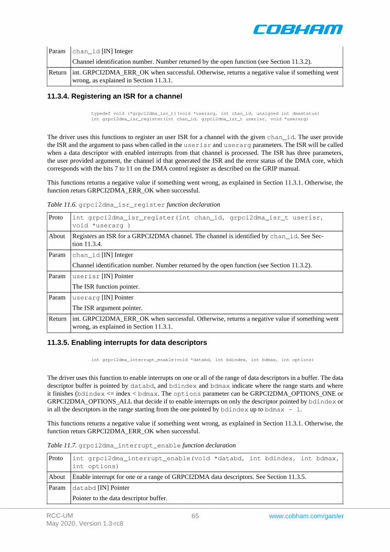
RCC-UMMay 2020, Version 1.3-rc8
65 www.cobham.com/gaisler
chan_id [IN] IntegerParam
Channel identification number. Number returned by the open function (see Section 11.3.2).
Return int. GRPCI2DMA_ERR_OK when successful. Otherwise, returns a negative value if something wentwrong, as explained in Section 11.3.1.
11.3.4. Registering an ISR for a channel
typedef void (*grpci2dma_isr_t)(void *userarg, int chan_id, unsigned int dmastatus) int grpci2dma_isr_register(int chan_id, grpci2dma_isr_t userisr, void *userarg)
The driver uses this functions to register an user ISR for a channel with the given chan_id. The user providethe ISR and the argument to pass when called in the userisr and userarg parameters. The ISR will be calledwhen a data descriptor with enabled interrupts from that channel is processed. The ISR has three parameters,the user provided argument, the channel id that generated the ISR and the error status of the DMA core, whichcorresponds with the bits 7 to 11 on the DMA control register as described on the GRIP manual.
This functions returns a negative value if something went wrong, as explained in Section 11.3.1. Otherwise, thefunction returs GRPCI2DMA_ERR_OK when successful.
Table 11.6. grpci2dma_isr_register function declaration
Proto int grpci2dma_isr_register(int chan_id, grpci2dma_isr_t userisr,void *userarg )
About Registers an ISR for a GRPCI2DMA channel. The channel is identified by chan_id. See Sec-tion 11.3.4.
chan_id [IN] IntegerParam
Channel identification number. Number returned by the open function (see Section 11.3.2).
userisr [IN] PointerParam
The ISR function pointer.
userarg [IN] PointerParam
The ISR argument pointer.
Return int. GRPCI2DMA_ERR_OK when successful. Otherwise, returns a negative value if something wentwrong, as explained in Section 11.3.1.
11.3.5. Enabling interrupts for data descriptors
int grpci2dma_interrupt_enable(void *databd, int bdindex, int bdmax, int options)
The driver uses this function to enable interrupts on one or all of the range of data descriptors in a buffer. The datadescriptor buffer is pointed by databd, and bdindex and bdmax indicate where the range starts and whereit finishes (bdindex <= index < bdmax. The options parameter can be GRPCI2DMA_OPTIONS_ONE orGRPCI2DMA_OPTIONS_ALL that decide if to enable interrupts on only the descriptor pointed by bdindex orin all the descriptors in the range starting from the one pointed by bdindex up to bdmax - 1.
This functions returns a negative value if something went wrong, as explained in Section 11.3.1. Otherwise, thefunction returs GRPCI2DMA_ERR_OK when successful.
Table 11.7. grpci2dma_interrupt_enable function declaration
Proto int grpci2dma_interrupt_enable(void *databd, int bdindex, int bdmax,int options)
About Enable interrupt for one or a range of GRPCI2DMA data descriptors. See Section 11.3.5.
databd [IN] PointerParam
Pointer to the data descriptor buffer.
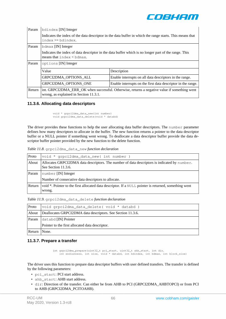
RCC-UMMay 2020, Version 1.3-rc8
66 www.cobham.com/gaisler
bdindex [IN] IntegerParam
Indicates the index of the data descriptor in the data buffer in which the range starts. This means thatindex >= bdindex.
bdmax [IN] IntegerParam
Indicates the index of data descriptor in the data buffer which is no longer part of the range. Thismeans that index < bdmax.
options [IN] Integer
Value Description
GRPCI2DMA_OPTIONS_ALL Enable interrupts on all data descriptors in the range.
Param
GRPCI2DMA_OPTIONS_ONE Enable interrupts on the first data descriptor in the range.
Return int. GRPCI2DMA_ERR_OK when successful. Otherwise, returns a negative value if something wentwrong, as explained in Section 11.3.1.
11.3.6. Allocating data descriptors
void * grpci2dma_data_new(int number) void grpci2dma_data_delete(void * databd)
The driver provides these functions to help the user allocating data buffer descriptors. The number parameterdefines how many descriptors to allocate in the buffer. The new function returns a pointer to the data descriptorbuffer or a NULL pointer if something went wrong. To deallocate a data descriptor buffer provide the data de-scriptor buffer pointer provided by the new function to the delete function.
Table 11.8. grpci2dma_data_new function declaration
Proto void * grpci2dma_data_new( int number )
About Allocates GRPCI2DMA data descriptors. The number of data descriptors is indicated by number.See Section 11.3.6.
number [IN] IntegerParam
Number of consecutive data descriptors to allocate.
Return void *. Pointer to the first allocated data descriptor. If a NULL pointer is returned, something wentwrong.
Table 11.9. grpci2dma_data_delete function declaration
Proto void grpci2dma_data_delete( void * databd )
About Deallocates GRPCI2DMA data descriptors. See Section 11.3.6.
databd [IN] PointerParam
Pointer to the first allocated data descriptor.
Return None.
11.3.7. Prepare a transfer
int grpci2dma_prepare(uint32_t pci_start, uint32_t ahb_start, int dir, int endianness, int size, void * databd, int bdindex, int bdmax, int block_size)
The driver uses this function to prepare data descriptor buffers with user defined transfers. The transfer is definedby the following parameters:
• pci_start: PCI start address.• ahb_start: AHB start address.• dir: Direction of the transfer. Can either be from AHB to PCI (GRPCI2DMA_AHBTOPCI) or from PCI
to AHB (GRPCI2DMA_PCITOAHB).
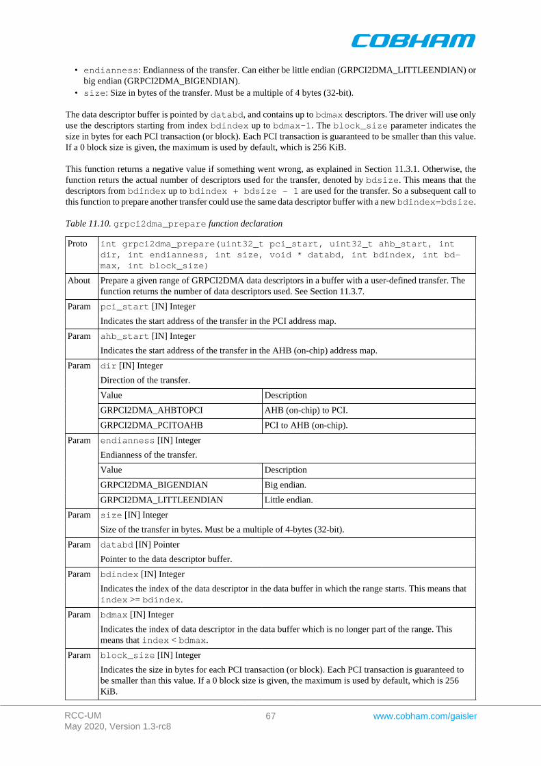
RCC-UMMay 2020, Version 1.3-rc8
67 www.cobham.com/gaisler
• endianness: Endianness of the transfer. Can either be little endian (GRPCI2DMA_LITTLEENDIAN) orbig endian (GRPCI2DMA_BIGENDIAN).
• size: Size in bytes of the transfer. Must be a multiple of 4 bytes (32-bit).
The data descriptor buffer is pointed by databd, and contains up to bdmax descriptors. The driver will use onlyuse the descriptors starting from index bdindex up to bdmax-1. The block_size parameter indicates thesize in bytes for each PCI transaction (or block). Each PCI transaction is guaranteed to be smaller than this value.If a 0 block size is given, the maximum is used by default, which is 256 KiB.
This function returns a negative value if something went wrong, as explained in Section 11.3.1. Otherwise, thefunction returs the actual number of descriptors used for the transfer, denoted by bdsize. This means that thedescriptors from bdindex up to bdindex + bdsize - 1 are used for the transfer. So a subsequent call tothis function to prepare another transfer could use the same data descriptor buffer with a new bdindex=bdsize.
Table 11.10. grpci2dma_prepare function declaration
Proto int grpci2dma_prepare(uint32_t pci_start, uint32_t ahb_start, intdir, int endianness, int size, void * databd, int bdindex, int bd-max, int block_size)
About Prepare a given range of GRPCI2DMA data descriptors in a buffer with a user-defined transfer. Thefunction returns the number of data descriptors used. See Section 11.3.7.
pci_start [IN] IntegerParam
Indicates the start address of the transfer in the PCI address map.
ahb_start [IN] IntegerParam
Indicates the start address of the transfer in the AHB (on-chip) address map.
dir [IN] Integer
Direction of the transfer.
Value Description
GRPCI2DMA_AHBTOPCI AHB (on-chip) to PCI.
Param
GRPCI2DMA_PCITOAHB PCI to AHB (on-chip).
endianness [IN] Integer
Endianness of the transfer.
Value Description
GRPCI2DMA_BIGENDIAN Big endian.
Param
GRPCI2DMA_LITTLEENDIAN Little endian.
size [IN] IntegerParam
Size of the transfer in bytes. Must be a multiple of 4-bytes (32-bit).
databd [IN] PointerParam
Pointer to the data descriptor buffer.
bdindex [IN] IntegerParam
Indicates the index of the data descriptor in the data buffer in which the range starts. This means thatindex >= bdindex.
bdmax [IN] IntegerParam
Indicates the index of data descriptor in the data buffer which is no longer part of the range. Thismeans that index < bdmax.
block_size [IN] IntegerParam
Indicates the size in bytes for each PCI transaction (or block). Each PCI transaction is guaranteed tobe smaller than this value. If a 0 block size is given, the maximum is used by default, which is 256KiB.
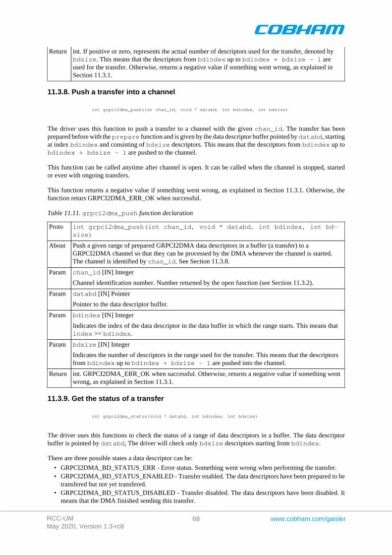
RCC-UMMay 2020, Version 1.3-rc8
68 www.cobham.com/gaisler
Return int. If positive or zero, represents the actual number of descriptors used for the transfer, denoted bybdsize. This means that the descriptors from bdindex up to bdindex + bdsize - 1 areused for the transfer. Otherwise, returns a negative value if something went wrong, as explained inSection 11.3.1.
11.3.8. Push a transfer into a channel
int grpci2dma_push(int chan_id, void * databd, int bdindex, int bdsize)
The driver uses this function to push a transfer to a channel with the given chan_id. The transfer has beenprepared before with the prepare function and is given by the data descriptor buffer pointed by databd, startingat index bdindex and consisting of bdsize descriptors. This means that the descriptors from bdindex up tobdindex + bdsize - 1 are pushed to the channel.
This function can be called anytime after channel is open. It can be called when the channel is stopped, startedor even with ongoing transfers.
This function returns a negative value if something went wrong, as explained in Section 11.3.1. Otherwise, thefunction returs GRPCI2DMA_ERR_OK when successful.
Table 11.11. grpci2dma_push function declaration
Proto int grpci2dma_push(int chan_id, void * databd, int bdindex, int bd-size)
About Push a given range of prepared GRPCI2DMA data descriptors in a buffer (a transfer) to aGRPCI2DMA channel so that they can be processed by the DMA whenever the channel is started.The channel is identified by chan_id. See Section 11.3.8.
chan_id [IN] IntegerParam
Channel identification number. Number returned by the open function (see Section 11.3.2).
databd [IN] PointerParam
Pointer to the data descriptor buffer.
bdindex [IN] IntegerParam
Indicates the index of the data descriptor in the data buffer in which the range starts. This means thatindex >= bdindex.
bdsize [IN] IntegerParam
Indicates the number of descriptors in the range used for the transfer. This means that the descriptorsfrom bdindex up to bdindex + bdsize - 1 are pushed into the channel.
Return int. GRPCI2DMA_ERR_OK when successful. Otherwise, returns a negative value if something wentwrong, as explained in Section 11.3.1.
11.3.9. Get the status of a transfer
int grpci2dma_status(void * databd, int bdindex, int bdsize)
The driver uses this functions to check the status of a range of data descriptors in a buffer. The data descriptorbuffer is pointed by databd, The driver will check only bdsize descriptors starting from bdindex.
There are three possible states a data descriptor can be:
• GRPCI2DMA_BD_STATUS_ERR - Error status. Something went wrong when performing the transfer.• GRPCI2DMA_BD_STATUS_ENABLED - Transfer enabled. The data descriptors have been prepared to be
transfered but not yet transfered.• GRPCI2DMA_BD_STATUS_DISABLED - Transfer disabled. The data descriptors have been disabled. It
means that the DMA finished sending this transfer.
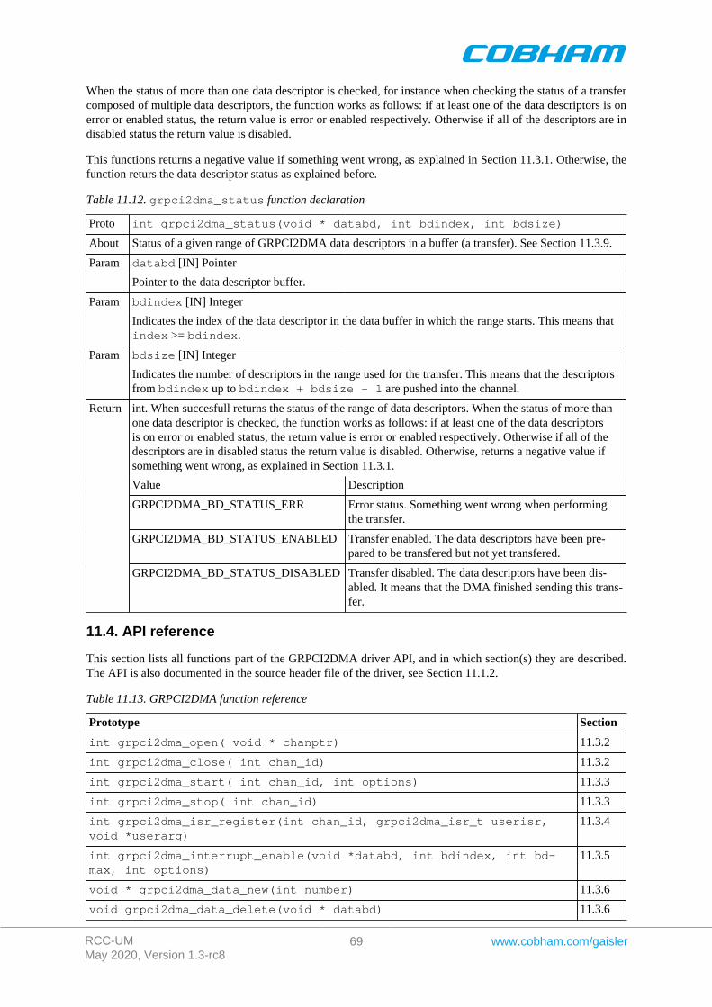
RCC-UMMay 2020, Version 1.3-rc8
69 www.cobham.com/gaisler
When the status of more than one data descriptor is checked, for instance when checking the status of a transfercomposed of multiple data descriptors, the function works as follows: if at least one of the data descriptors is onerror or enabled status, the return value is error or enabled respectively. Otherwise if all of the descriptors are indisabled status the return value is disabled.
This functions returns a negative value if something went wrong, as explained in Section 11.3.1. Otherwise, thefunction returs the data descriptor status as explained before.
Table 11.12. grpci2dma_status function declaration
Proto int grpci2dma_status(void * databd, int bdindex, int bdsize)
About Status of a given range of GRPCI2DMA data descriptors in a buffer (a transfer). See Section 11.3.9.
databd [IN] PointerParam
Pointer to the data descriptor buffer.
bdindex [IN] IntegerParam
Indicates the index of the data descriptor in the data buffer in which the range starts. This means thatindex >= bdindex.
bdsize [IN] IntegerParam
Indicates the number of descriptors in the range used for the transfer. This means that the descriptorsfrom bdindex up to bdindex + bdsize - 1 are pushed into the channel.
int. When succesfull returns the status of the range of data descriptors. When the status of more thanone data descriptor is checked, the function works as follows: if at least one of the data descriptorsis on error or enabled status, the return value is error or enabled respectively. Otherwise if all of thedescriptors are in disabled status the return value is disabled. Otherwise, returns a negative value ifsomething went wrong, as explained in Section 11.3.1.
Value Description
GRPCI2DMA_BD_STATUS_ERR Error status. Something went wrong when performingthe transfer.
GRPCI2DMA_BD_STATUS_ENABLED Transfer enabled. The data descriptors have been pre-pared to be transfered but not yet transfered.
Return
GRPCI2DMA_BD_STATUS_DISABLED Transfer disabled. The data descriptors have been dis-abled. It means that the DMA finished sending this trans-fer.
11.4. API reference
This section lists all functions part of the GRPCI2DMA driver API, and in which section(s) they are described.The API is also documented in the source header file of the driver, see Section 11.1.2.
Table 11.13. GRPCI2DMA function reference
Prototype Section
int grpci2dma_open( void * chanptr) 11.3.2
int grpci2dma_close( int chan_id) 11.3.2
int grpci2dma_start( int chan_id, int options) 11.3.3
int grpci2dma_stop( int chan_id) 11.3.3
int grpci2dma_isr_register(int chan_id, grpci2dma_isr_t userisr,void *userarg)
11.3.4
int grpci2dma_interrupt_enable(void *databd, int bdindex, int bd-max, int options)
11.3.5
void * grpci2dma_data_new(int number) 11.3.6
void grpci2dma_data_delete(void * databd) 11.3.6
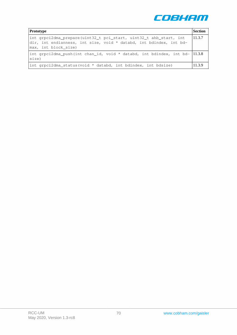
RCC-UMMay 2020, Version 1.3-rc8
70 www.cobham.com/gaisler
Prototype Section
int grpci2dma_prepare(uint32_t pci_start, uint32_t ahb_start, intdir, int endianness, int size, void * databd, int bdindex, int bd-max, int block_size)
11.3.7
int grpci2dma_push(int chan_id, void * databd, int bdindex, int bd-size)
11.3.8
int grpci2dma_status(void * databd, int bdindex, int bdsize) 11.3.9
RCC-UMMay 2020, Version 1.3-rc8
71 www.cobham.com/gaisler
Chapter 12. GR-RASTA-ADCDAC PCI peripheral
This section describes the GR-RASTA-ADCDAC PCI peripheral driver.
The GR-RASTA-ADCDAC driver require the Driver Manager and that the PCI bus is big endian.
The GR-RASTA-ADCDAC driver is a bus driver providing an AMBA Plug & Play bus. The driver first setsup the target PCI register such as PCI Master enable and the address translation registers. Once the PCI targetis set up the driver creates an ambapp_bus that scans the bus and assigns the appropriate drivers. This driverprovides interrupt handling and memory address translation on the internal AMBA bus so that the drivers canfunction as expected.
The driver resources of the AMBA bus created by the GR-RASTA-ADCDAC driver can be assigned by callinggr_rasta_adcdac_set_resource as defined by gr_rasta_adcdac.h.
The driver resources of the AMBA bus created by the GR-RASTA-ADCDAC driver can be assigned by overridingthe weak default bus resource array gr_rasta_adcdac_resources[] of the driver. It contains a array ofpointers to bus resources where index=N determines the bus resources for GR-RASTA-ADCDAC[N] board. Thearray is declared in gr_rasta_adcdac.h. The driver resources can be used to set up the memory parameters, configurelocations of the DMA areas and other parameters of GRCAN, GRADCDAC and all other supported cores. Pleasesee respective driver for available configuration options.
RCC-UMMay 2020, Version 1.3-rc8
72 www.cobham.com/gaisler
Chapter 13. GR-RASTA-IO PCI peripheral
This section describes the GR-RASTA-IO PCI peripheral driver.
The GR-RASTA-IO driver require the Driver Manager and that the PCI bus is big endian.
The GR-RASTA-IO driver is a bus driver providing an AMBA Plug & Play bus. The driver first sets up the targetPCI register such as PCI Master enable and the address translation registers. Once the PCI target is set up thedriver creates an ambapp_bus that scans the bus and assigns the appropriate drivers. This driver provides interrupthandling and memory address translation on the internal AMBA bus so that the drivers can function as expected.
The driver resources of the AMBA bus created by the GR-RASTA-IO driver can be assigned by overriding theweak default bus resource array gr_rasta_io_resources[] of the driver. It contains a array of pointers tobus resources where index=N determines the bus resources for GR-RASTA-IO[N] board. The array is declaredin gr_rasta_io.h. The driver resources can be used to set up the memory parameters and configure locations ofthe DMA areas of 1553BRM, GRCAN, GRSPW cores. Please see respective driver for available configurationoptions.
RCC-UMMay 2020, Version 1.3-rc8
73 www.cobham.com/gaisler
Chapter 14. GR-RASTA-TMTC PCI peripheral
This section describes the GR-RASTA-TMTC PCI peripheral driver.
The GR-RASTA-TMTC driver require the Driver Manager and that the PCI bus is big endian.
The GR-RASTA-TMTC driver is a bus driver providing an AMBA Plug & Play bus. The driver first sets up thetarget PCI register such as PCI Master enable and the address translation registers. Once the PCI target is set up thedriver creates an ambapp_bus that scans the bus and assigns the appropriate drivers. This driver provides interrupthandling and memory address translation on the internal AMBA bus so that the drivers can function as expected.
The driver resources of the AMBA bus created by the GR-RASTA-TMTC driver can be assigned by overridingthe weak default bus resource array gr_rasta_tmtc_resources[] of the driver. It contains a array ofpointers to bus resources where index=N determines the bus resources for GR-RASTA-TMTC[N] board. Thearray is declared in gr_rasta_tmtc.h. The driver resources can be used to set up the memory parameters andconfigure locations of the DMA areas of GRTC, GRTM, GRSPW cores. Please see respective driver for availableconfiguration options.
RCC-UMMay 2020, Version 1.3-rc8
74 www.cobham.com/gaisler
Chapter 15. GR-RASTA-SPW_ROUTER PCI Peripheral
This section describes the GR-RASTA-SPW_ROUTER PCI peripheral driver.
The GR-RASTA-SPW_ROUTER driver require the RTEMS Driver Manager and that the PCI bus is big endian.
The GR-RASTA-SPW-ROUTER driver is a bus driver providing an AMBA Plug & Play bus. The driver first setsup the target PCI register such as PCI Master enable and the address translation registers. Once the PCI target isset up the driver creates an ambapp_bus that scans the bus and assigns the appropriate drivers. This driver providesinterrupt handling and memory address translation on the internal AMBA bus so that the drivers can function asexpected.
The driver resources of the AMBA bus created by the GR-RASTA-SPW_ROUTER driver can be assigned byoverriding the weak default bus resource array gr_rasta_spw_router_resources[] of the driver. It contains a arrayof pointers to bus resources where index=N determines the bus resources for GR-RASTA-SPW_ROUTER[N]board. The driver resources can be used to set up the memory parameters and configure locations of the DMA areasof GRSPW2 AMBA port cores. Please see GRSPW driver documentation for available configuration options.
RCC-UMMay 2020, Version 1.3-rc8
75 www.cobham.com/gaisler
Chapter 16. GR-CPCI-LEON4-N2X PCI Peripheral
This section describes the GR-CPCI-LEON4-N2X PCI peripheral driver.
The GR-CPCI-LEON4-N2X driver require the RTEMS Driver Manager and that the PCI bus is big endian.
The GR-CPCI-LEON4-N2X driver is a bus driver providing an AMBA Plug & Play bus. The driver first sets upthe target PCI register such as PCI Master enable and the address translation registers. The clock gating unit is bydefault set up so that all functionality is enabled. Once the PCI target is set up the driver creates an ambapp_busthat scans the bus and assigns the appropriate drivers. This driver provides interrupt handling and memory addresstranslation on the internal AMBA bus so that the drivers can function as expected.
The driver resources of the AMBA bus created by the driver can be assigned by overriding the weak default busresource array gr_cpci_leon4_n2x_resources[] of the driver. It contains a array of pointers to bus re-sources where index=N determines the bus resources for GR-CPCI-LEON4-N2X[N] board. The array is declaredin gr_cpci_leon4_n2x.h. The driver resources can be used to set up the memory parameters and for con-figuring other driver options such as the base DMA area address of the SpaceWire cores. Please see respectivedriver for available configuration options.
16.1. Driver registration
The driver must be registered to the driver manager by adding theCONFIGURE_DRIVER_PCI_GR_LEON4_N2X define in the RTEMS project configuration. This process is de-scribed in the driver manager chapter.
16.2. Driver resource configuration
The driver can be configured using driver resources as described in the driver manager chapter. Below is a de-scription of configurable driver parameters. The driver parameters is unique per PCI device and configured in thePCI bus driver resources array. The parameters are all optional, the parameters only overrides the default values.However the ambaFreq paramter is typically required.
Table 16.1. GR-CPCI-LEON4-N2X driver parameter description
Name Type Parameter Description
ahbmst2pci INT PCI base address of the 1Gbyte AMBA->PCI window. Default to RAM start ad-dress.
ambaFreq INT Frequency in Hz of the LEON4-N2X AMBA bus. Defaults to 200MHz.
cgEnMask INT Clock gating enable/disable mask. Each bit in the mask corresponds to one bit thethe clock gate unit (one clock tree), set to 1 to enable or 0 to disable individualclock trees.
bar0 INT PCI target BAR0 AMBA access address. Defaults to 0x00000000 (L2-cache mainmemory)
bar1 INT PCI target BAR1 AMBA access address. Defaults to 0xf0000000 (L2-cache regis-ters)
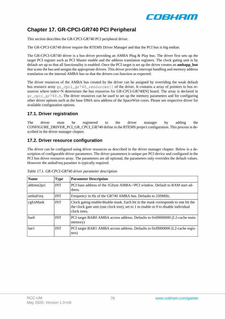
RCC-UMMay 2020, Version 1.3-rc8
76 www.cobham.com/gaisler
Chapter 17. GR-CPCI-GR740 PCI Peripheral
This section describes the GR-CPCI-GR740 PCI peripheral driver.
The GR-CPCI-GR740 driver require the RTEMS Driver Manager and that the PCI bus is big endian.
The GR-CPCI-GR740 driver is a bus driver providing an AMBA Plug & Play bus. The driver first sets up thetarget PCI register such as PCI Master enable and the address translation registers. The clock gating unit is bydefault set up so that all functionality is enabled. Once the PCI target is set up the driver creates an ambapp_busthat scans the bus and assigns the appropriate drivers. This driver provides interrupt handling and memory addresstranslation on the internal AMBA bus so that the drivers can function as expected.
The driver resources of the AMBA bus created by the driver can be assigned by overriding the weak defaultbus resource array gr_cpci_gr740_resources[] of the driver. It contains a array of pointers to bus re-sources where index=N determines the bus resources for GR-CPCI-GR740[N] board. The array is declared ingr_cpci_gr740.h. The driver resources can be used to set up the memory parameters and for configuringother driver options such as the base DMA area address of the SpaceWire cores. Please see respective driver foravailable configuration options.
17.1. Driver registration
The driver must be registered to the driver manager by adding theCONFIGURE_DRIVER_PCI_GR_CPCI_GR740 define in the RTEMS project configuration. This process is de-scribed in the driver manager chapter.
17.2. Driver resource configuration
The driver can be configured using driver resources as described in the driver manager chapter. Below is a de-scription of configurable driver parameters. The driver parameters is unique per PCI device and configured in thePCI bus driver resources array. The parameters are all optional, the parameters only overrides the default values.However the ambaFreq paramter is typically required.
Table 17.1. GR-CPCI-GR740 driver parameter description
Name Type Parameter Description
ahbmst2pci INT PCI base address of the 1Gbyte AMBA->PCI window. Default to RAM start ad-dress.
ambaFreq INT Frequency in Hz of the GR740 AMBA bus. Defaults to 250MHz.
cgEnMask INT Clock gating enable/disable mask. Each bit in the mask corresponds to one bit thethe clock gate unit (one clock tree), set to 1 to enable or 0 to disable individualclock trees.
bar0 INT PCI target BAR0 AMBA access address. Defaults to 0x00000000 (L2-cache mainmemory)
bar1 INT PCI target BAR1 AMBA access address. Defaults to 0xf0000000 (L2-cache regis-ters)
RCC-UMMay 2020, Version 1.3-rc8
77 www.cobham.com/gaisler
Chapter 18. GRSPW Packet driver
18.1. Introduction
This section describes the GRSPW packet driver for RTEMS The packet driver will replace the older GRSPWdriver in the future.
It is an advantage to understand the SpaceWire bus/protocols, GRSPW hardware and software driver design whendeveloping using the user interface in Section 18.3 and Section 18.4. The Section 18.2.1 describes the overallsoftware design of the driver.
18.1.1. GRSPW packet driver vs. old GRSPW driver
This driver is a complete redesign of the older GRSPW driver. The user interfaces to GRSPW devices using anAPI rather than using the standard UNIX file procedures like open(), read(), ioctl() and so on. The driver useslinked lists of packet buffers to receive and transmit SpaceWire packets. Before the user called read() or write() tocopy data into/from the GRSPW DMA buffers, where each call received or transmitted a single packet at a time.The packet driver implements a new API that allows efficient custom data buffer handling providing zero-copyability, SMP support and multiple DMA channel support. The link control handling has been separated from theDMA handling, just to name a few improvements.
18.1.2. Hardware Support
The GRSPW cores user interface are documented in the GRIP Core User's manual. Below is a list of the majorhardware features it supports:
• GRSPW, GRSPW2 and GRSPW2_DMA (router AMBA port)• Multiple DMA channels• Time Code• Link Control• Port Control• RMAP Control• SpaceWire Interrupt codes• Interrupt handling• Multi-processor SMP support
18.1.3. Driver sources
The driver sources and definitions are listed in the table below, the path is given relative to the RTEMS sourcetree rtems-5/c/src/lib/libbsp/sparc.
Table 18.1. Source Location
Filename Description
shared/include/grspw_pkt.h GRSPW user interface definition
shared/spw/grspw_pkt.c GRSPW driver implementation
18.1.4. Show routines
There are currently no show routines.
18.1.5. Examples
Examples are available in the src/samples/spw/ directory in the RCC distribution.
18.1.6. Known driver limitations
The known limitations in the GRSPW Packet driver exists listed below:
• The shutdown of the work thread when destroying the message queue may be problematic.
RCC-UMMay 2020, Version 1.3-rc8
78 www.cobham.com/gaisler
• The statistics counters are not atomic, clearing at the same the interrupt handler is called could cause invalidstatistics, one must disable interrupt when reading/clearing.
• The SpaceWire Interrupt code support is not documented yet.
18.2. Software design overview
18.2.1. Overview
The driver has been implemented using the Driver Manager Framework. The driver provides a kernel functioninterface, an API, rather than implementing a IO system device. The API is designed for multi-threadding allowingmultiple threads to operate on the link, RX and TX DMA channel interfaces independently. The driver API hasbeen split up in two major parts listed below:
• Device interface, see Section 18.3.• DMA channel interface, see Section 18.4.
GRSPW device parameters that affects the GRSPW core and all DMA channels are accessed over the device APIwhereas DMA specific settings and buffer handling are accessed over the per DMA channel API. A GRSPW2device may implement up to four DMA channels.
In order to access the driver the first thing is to open a GRSPW device using the device interface.
For controlling the device one must open a GRSPW device using 'id = grspw_open(dev_index)' andcall appropriate device control functions. Device operations naturally affects all DMA channels, for example whenthe link is disabled all DMA activity pause. However there is no connection software wise between the devicefunctions and DMA function, except from that the grspw_close requires that all of its DMA channels havebeen closed. Closing a device fails if DMA channels are still open.
Packets are transferred using DMA channels. To open a DMA channel one calls 'dma_id =grspw_dma_open(id, dmachan_index)' and use the appropriate transmission function with thedma_id to identify which DMA channel used.
18.2.2. Driver resource configuration
It is possible to configure the GRSPW driver by driver resources assigned at compile time. The resources are setindividually per GRSPW device. The table below shows all options.
Table 18.2. GRSPW packet driver resources
Name Type Parameter description
nDma INT Number of DMA channels to present to user. This is used to limit the number of DMAchannels and thereby save memory. This option does not have an effect if it is less thanone or greater than the number of DMA channels present in the hardware.
bdDmaArea INT Custom RX and TX DMA descriptor table area address. The driver always requires0x800 Bytes memory per DMA channel. This means that at least (nDMA * 0x400 * 2)Bytes must be available.
The address must be aligned to 0x400.
18.2.3. Initialization
During early initialization when the operating system boots the driver performs some basic GRSPW device andsoftware initialization. The following steps are performed or not performed:
• GRSPW device and DMA channels I/O registers are initialized to a state where most are zero.• DMA is stopped on all channels• Link state and settings are not changed (RMAP may be active).• RMAP settings untouched (RMAP may be active).• Port select untouched (RMAP may be active).• Time Codes are disabled and TC register cleared.• IRQ generation disabled.
RCC-UMMay 2020, Version 1.3-rc8
79 www.cobham.com/gaisler
• Status Register cleared.• Node address / DMA channels node address is untouched (RMAP may be active).• Hardware capabilities are read and potentially overridden by nDMA configuration option, see Section 18.2.2.• Device index determined.
18.2.4. Link control
The GRSPW link interface handles the communication on the SpaceWire network. It consists of a transmitter,receiver, a FSM and FIFO interfaces. The current link state, status indicating past failures, parameters that affectthe link interface such as transmitter frequency for example is controlled using the GRSPW register interface.
The SpaceWire link is controlled using the software device interface. The driver initialization sequence duringboot does not affect the link parameters or state. The link is controlled separately from the DMA channels, eventhough the link goes out from run-mode this does not affect the DMA interface. The DMA activity of all channelsare of course paused. It is possible to configure the driver to disable the link on certain error interrupts.
The link can be disabled when a link error is detected by the GRSPW interrupt handler. There are two optionswhich can be combined, either the DMA transmitter is disabled on error (disabled by hardware) or the softwareinterrupt handler disables the link on link error events selected by the user. When software disables the link thework-task is informed and stops all DMA channels, thus grspw_dma_stop() is called for each DMA chan-nel by the work-task. The GRSPW interrupt handler will disable the link by writing "Link Disable" bit and clear-ing "Link Start" bit on link errors. The user is responsible to restart the link interface again. The status register(grspw_link_status()) and statistics interface can be used to determine which error(s) happened. The twooptions are configured by the link control interface of the device API using function grspw_link_ctrl().
To make hardware disable the DMA transmitter automatically on error the option (LINKOPTS_DIS_ONERR)is used.
To activate the GRSWP interrupt routine when any link error occurs, the bitmask option Enable ErrorLink IRQ (LINKOPTS_EIRQ) shall be set. The bitmask options described as Disable Link on XX Error(LINKOPTS_DIS_ON_*) are used to select which events shall actually cause link disable in the interrupt routineand inform the work-task of a shutdown stop.
NOTE: The options LINKOPTS_DIS_ON* are in effect even when the option LINKOPTS_EIRQ is disabled.Thus, an interrupt routine invocation caused by a DMA channel interrupt event may disable the link in case anyof the conditions in LINKOPTS_DIS_ON_* are satisfied.
Statistics about the link errors can be read from the driver, see Section 18.3.8.
It is possible to circumvent the drivers action of clearing link status events in the GRSPW status register fromthe interrupt routine. This can be used for example when the user wants to detect and handle all occurrences ofa specific link event. The function grspw_link_ctrl() is used to configure this via the stscfg parameterwith values LINKSTS_*. If a bit is set in this configuration parameter, the corresponding bit in the GRSPW statusregister is cleared by the interrupt routine. If the bit is not set, the interrupt routine will never clear the statusflag and the user has full control of it. The status event can then be manually read and cleared with functionsgrspw_link_status() and grspw_link_status_clr().
NOTE: Statistics counters for events which are configured to be circumvented by the driver, as described above,shall not be relied upon.
Function names prefix: grspw_link_*().
18.2.5. Time Code support
The GRSPW supports sending and receiving SpaceWire Time Codes. An interrupt can optionally be generated onTime Code reception and the last Time Code can be read out from a GRSPW register.
The GRSPW core's Time Code interface can be controlled from the device API. One can generate Time Codes andread out the last received or generated Time Code. An user assignable interrupt handler can be used to detect andhandle Time Code reception, the callback is called from the GRSPW interrupt routine thus from interrupt context.
RCC-UMMay 2020, Version 1.3-rc8
80 www.cobham.com/gaisler
Function names prefix: grspw_tc_*()
18.2.6. RMAP support
The GRSPW device has optional support for an RMAP target implemented in hardware. The target interface isable to interpret RMAP protocol (protid=1) requests, take the necessary actions on the AMBA bus and generatea RMAP response without the software's knowledge or interaction. The RMAP target can be disabled in orderto implement the RMAP protocol in software instead using the DMA operations. The RMAP CRC algorithmoptionally present in hardware can also be used for checksumming the data payload.
The device interface is used to get the RMAP features supported by the hardware and configuring the belowRMAP parameters:
• Probe if RMAP and RMAP CRC is supported by hardware• RMAP enable/disable• SpaceWire DESTKEY of RMAP packets
The SpaceWire node address, which also affects the RMAP target, is controlled from the address configurationroutines, see Section 18.2.8.
Function names prefix: grspw_rmap_*()
18.2.7. Port support
The GRSPW device has optional support for two ports (two connectors), where only one port can be active at atime. The active SpaceWire port is either forced by the user or auto selected by the hardware depending on thelink state of the SpaceWire ports at a certain condition.
The device interface is used to get information about the GRSPW hardware port support, current set up and tocontrol how the active port is selected.
Function names prefix: grspw_port_*()
18.2.8. SpaceWire node address configuration
The GRSPW core supports assigning a SpaceWire node address or a range of addresses. The address affects thereceived SpaceWire Packets, both to the RMAP target and to the DMA receiver. If a received packet does notmatch the node address it is dropped and the GRSPW status indicates that one or more packets with invalid addresswas received.
The GRSPW2 and GRSPW2_DMA cores that implements multiple DMA channels use the node address as away to determine which DMA channel a received packet shall appear at. A unique node address or range of nodeaddresses per DMA channel must be configured in this case.
It is also possible to enable promiscuous mode to enable all node addresses to be accepted into the first DMAchannel, this option does not affect the RMAP target node address decoding.
The GRSPW SpaceWire node address configuration is controlled using the device interface. A specific DMAchannel's node address is thus affected by the "global" device API and not controllable using the DMA channelinterface.
If supported by hardware the node address can be removed before DMA writes the packet to memory. This is aconfiguration option per DMA channel using the DMA channel API.
Function names prefix: grspw_addr_*()
18.2.9. SpaceWire Interrupt Code support
The GRSPW2 has optionally support for receiving and generating SpaceWire Interrupt codes. The Interrupt Codesimplementation is based on the Time Code service but with a different Time Code Control content.
The SpaceWire Interrupt Code interface are controlled from the device interface.
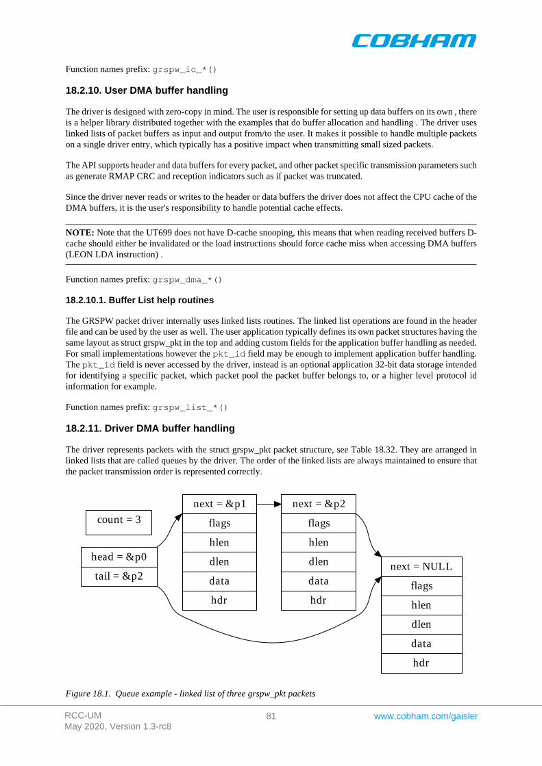
RCC-UMMay 2020, Version 1.3-rc8
81 www.cobham.com/gaisler
Function names prefix: grspw_ic_*()
18.2.10. User DMA buffer handling
The driver is designed with zero-copy in mind. The user is responsible for setting up data buffers on its own , thereis a helper library distributed together with the examples that do buffer allocation and handling . The driver useslinked lists of packet buffers as input and output from/to the user. It makes it possible to handle multiple packetson a single driver entry, which typically has a positive impact when transmitting small sized packets.
The API supports header and data buffers for every packet, and other packet specific transmission parameters suchas generate RMAP CRC and reception indicators such as if packet was truncated.
Since the driver never reads or writes to the header or data buffers the driver does not affect the CPU cache of theDMA buffers, it is the user's responsibility to handle potential cache effects.
NOTE: Note that the UT699 does not have D-cache snooping, this means that when reading received buffers D-cache should either be invalidated or the load instructions should force cache miss when accessing DMA buffers(LEON LDA instruction) .
Function names prefix: grspw_dma_*()
18.2.10.1. Buffer List help routines
The GRSPW packet driver internally uses linked lists routines. The linked list operations are found in the headerfile and can be used by the user as well. The user application typically defines its own packet structures having thesame layout as struct grspw_pkt in the top and adding custom fields for the application buffer handling as needed.For small implementations however the pkt_id field may be enough to implement application buffer handling.The pkt_id field is never accessed by the driver, instead is an optional application 32-bit data storage intendedfor identifying a specific packet, which packet pool the packet buffer belongs to, or a higher level protocol idinformation for example.
Function names prefix: grspw_list_*()
18.2.11. Driver DMA buffer handling
The driver represents packets with the struct grspw_pkt packet structure, see Table 18.32. They are arranged inlinked lists that are called queues by the driver. The order of the linked lists are always maintained to ensure thatthe packet transmission order is represented correctly.
head = &p0
tail = &p2
next = &p1
flags
hlen
dlen
data
hdr
next = NULL
flags
hlen
dlen
data
hdr
count = 3
next = &p2
flags
hlen
dlen
data
hdr
Figure 18.1. Queue example - linked list of three grspw_pkt packets
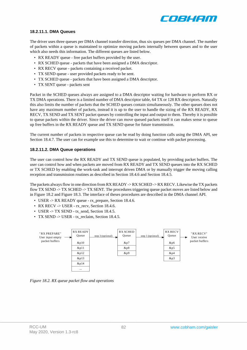
RCC-UMMay 2020, Version 1.3-rc8
82 www.cobham.com/gaisler
18.2.11.1. DMA Queues
The driver uses three queues per DMA channel transfer direction, thus six queues per DMA channel. The numberof packets within a queue is maintained to optimize moving packets internally between queues and to the userwhich also needs this information. The different queues are listed below.
• RX READY queue - free packet buffers provided by the user.• RX SCHED queue - packets that have been assigned a DMA descriptor.• RX RECV queue - packets containing a received packet.• TX SEND queue - user provided packets ready to be sent.• TX SCHED queue - packets that have been assigned a DMA descriptor.• TX SENT queue - packets sent
Packet in the SCHED queues always are assigned to a DMA descriptor waiting for hardware to perform RX orTX DMA operations. There is a limited number of DMA descriptor table, 64 TX or 128 RX descriptors. Naturallythis also limits the number of packets that the SCHED queues contain simultaneously. The other queues does nothave any maximum number of packets, instead it is up to the user to handle the sizing of the RX READY, RXRECV, TX SEND and TX SENT packet queues by controlling the input and output to them. Thereby it is possibleto queue packets within the driver. Since the driver can move queued packets itself it can makes sense to queueup free buffers in the RX READY queue and TX SEND queue for future transmission.
The current number of packets in respective queue can be read by doing function calls using the DMA API, seeSection 18.4.7. The user can for example use this to determine to wait or continue with packet processing.
18.2.11.2. DMA Queue operations
The user can control how the RX READY and TX SEND queue is populated, by providing packet buffers. Theuser can control how and when packets are moved from RX READY and TX SEND queues into the RX SCHEDor TX SCHED by enabling the work-task and interrupt driven DMA or by manually trigger the moving callingreception and transmission routines as described in Section 18.4.6 and Section 18.4.5.
The packets always flow in one direction from RX READY -> RX SCHED -> RX RECV. Likewise the TX packetsflow TX SEND -> TX SCHED -> TX SENT. The procedures triggering queue packet moves are listed below andin Figure 18.2 and Figure 18.3. The interface of theses procedures are described in the DMA channel API.
• USER -> RX READY queue - rx_prepare, Section 18.4.6.• RX RECV -> USER - rx_recv, Section 18.4.6.• USER -> TX SEND - tx_send, Section 18.4.5.• TX SEND -> USER - tx_reclaim, Section 18.4.5.
" RX PREPARE"User input empty
packet buffers
RX READYQueue
&p10
&p11
&p12
&p13
&p14
...
" RX RECV"User receive
packet buffers
RX SCHEDQueue
&p7
&p8
&p9
step 3 (optional)
RX RECVQueue
&p6
&p5
&p4
&p3
step 1 (optional)
Figure 18.2. RX queue packet flow and operations
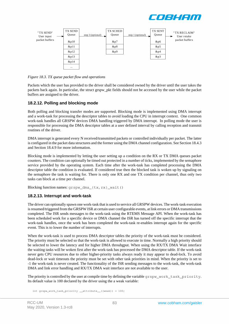
RCC-UMMay 2020, Version 1.3-rc8
83 www.cobham.com/gaisler
" TX SEND"User input
packet buffers
TX SENDQueue
&p10
&p11
&p12
&p13
&p14
...
" TX RECLAIM"User retake
packet buffers
TX SCHEDQueue
&p7
&p8
&p9
step 3 (optional)
TX SENTQueue
&p6
&p5
&p4
&p3
step 1 (optional)
Figure 18.3. TX queue packet flow and operations
Packets which the user has provided to the driver shall be considered owned by the driver until the user takes thepackets back again. In particular, the struct grspw_pkt fields should not be accessed by the user while the packetbuffers are assigned to the driver.
18.2.12. Polling and blocking mode
Both polling and blocking transfer modes are supported. Blocking mode is implemented using DMA interruptand a work-task for processing the descriptor tables to avoid loading the CPU in interrupt context. One commonwork-task handles all GRSPW devices DMA handling triggered by DMA interrupt. In polling mode the user isresponsible for processing the DMA descriptor tables at a user defined interval by calling reception and transmitroutines of the driver.
DMA interrupt is generated every N received/transmitted packets or controlled individually per packet. The latteris configured in the packet data structures and the former using the DMA channel configuration. See Section 18.4.3and Section 18.4.9 for more information.
Blocking mode is implemented by letting the user setting up a condition on the RX or TX DMA queues packetcounters. The condition can optionally be timed out protected in a number of ticks, implemented by the semaphoreservice provided by the operating system. Each time after the work-task has completed processing the DMAdescriptor table the condition is evaluated. If considered true then the blocked task is woken up by signaling onthe semaphore the task is waiting for. There is only one RX and one TX condition per channel, thus only twotasks can block at a time per channel.
Blocking function names: grspw_dma_{tx,rx}_wait()
18.2.13. Interrupt and work-task
The driver can optionally spawn one work-task that is used to service all GRSPW devices. The work-task executionis resumed/triggered from the GRSPW ISR at certain user configurable events, at link errors or DMA transmissionscompleted. The ISR sends messages to the work-task using the RTEMS Message API. When the work-task hasbeen scheduled work for a specific device or DMA channel the ISR has turned off the specific interrupt that thework-task handles, once the work has been completed the work-task re-enables interrupt again for the specificevent. This is to lower the number of interrupts.
When the work-task is used to process DMA descriptor tables the priority of the work-task must be considered.The priority must be selected so that the work-task is allowed to execute in time. Normally a high priority shouldbe selected to lower the latency and for higher DMA throuhgput. When using the RX/TX DMA Wait interfacethe waiting tasks will be woken first after the work-task has processed the DMA descriptor table. If the work-tasknever gets CPU resources due to other higher-priority tasks always ready it may appear to dead-lock. To avoiddead-lock or wait timeouts the priority must be set with other task priorities in mind. When the priority is set to-1 the work-task is never created. The functionality of the ISR sending messages to the work-task, the work-taskDMA and link error handling and RX/TX DMA wait interface are not available to the user.
The priority is controlled by the user at compile time by defining the variable grspw_work_task_priority.Its default value is 100 declared by the driver using the a weak variable:
int grspw_work_task_priority __attribute__((weak)) = 100;
RCC-UMMay 2020, Version 1.3-rc8
84 www.cobham.com/gaisler
NOTE: NOTE: The priority of the work-task is user configurable and must be assigned with the rest of theapplication's task priorities in mind so that it is allowed to execute and wake up the waiting/blocked user task(s).Otherwise the user task may be blocked forever or for too long.
The work-task can also be used to automatically stop DMA operation on certain link errors. This feature is enabledby activating the different Disable Link on XX Error (LINKOPTS_DIS_ON_*) options from the device API linkcontrol interface. See Section 18.2.4. For the configured link errors the GRSPW interrupt handler will trigger theshutdown work to start which will stop all DMA channels by calling grspw_dma_stop().
18.2.14. Starting and stopping DMA
The driver has been designed to make it clear which functionality belongs to the device and DMA channel APIs.The DMA API is affected by started and stopped mode, where in stopped mode means that DMA is not possibleand used to configure the DMA part of the driver. During started mode a DMA channel can accept incoming andsend packets. Each DMA channel controls its own state. Parts of the DMA API is not available in during stoppedmode and some during stopped mode to simplify the design. The device API is not affected by this.
Typically the DMA configuration is set and user buffers are initialized before DMA is started. The user can controlthe link interface separately from the DMA channel before and during DMA starts.
When the DMA channel is stopped by calling grspw_dma_stop() the driver will:
• Stop DMA transfers and DMA interrupts.• Stop accepting new packets for transmission and reception. However the DMA functions will still be open for
the user to retrieve sent and unsent TX packet buffers and to retrieve received and unused RX packet buffers.• Wake up blocked DMA threads and return to the caller. Tasks can be blocked waiting for TX/RX event by
using the TX/RX DMA wait functions.
The DMA close routines requires that the DMA channel is stopped. Similarly, the device close routine makes surethat all DMA channels are closed to be successful. This is to make sure that all user tasks has return and hardwareis in a good state. It is the user's responsibility to stop the DMA channel before closing.
DMA operational function names: grspw_dma_{start,stop}()
18.2.15. Thread concurrency
The driver has been designed to allow multi-threading. There are five parts that can be operated simulaneouslyby different or the same thread(s):
• Device (link control) interface.• DMA RX channel.• DMA TX channel.• work-task is a separate thread of execution.• Interrupt Service Routine.
There may be multiple DMA channels in a GRSPW device. DMA channels are operated independently of eachother. Each DMA channel has two semaphores to allow operations on different DMA channels simultaneouslyas well as simultaneous RX and TX operations on the same DMA channel. However multiple RX and TX tasksof the same RX or TX interface of the same DMA channel is possible but will temporarily lock each other outduring register and DMA descriptor table processing. The same semaphores are taken by the work-task duringDMA processing if the user has enabled it. There is a global device semaphore that manages device open/closeoperations that introduce dependencies between different GRSPW device and between DMA channels on thoseoperations. The DMA channels and device interface share the same GRSPW I/O registers which needs in somecases to be protected, they are protected from each other by using interrupt disabling (or spin-locks on SMP).
Each DMA channel also has two semahpores to implement blocking on RX/TX operations. The DMA RX/TXinterrupt wakes a worker which processes the DMA RX/TX descriptor tables and signals via the RX-WAIT andTX-WAIT that incomming/outgoing packets processing has finished.
The table below summarises the semaphore operations of a DMA channel that the driver makes.

RCC-UMMay 2020, Version 1.3-rc8
85 www.cobham.com/gaisler
Table 18.3. DMA channel semaphore operations.
Function Operation Semaphore Description
dma_open Init semaphores RX TX RX and TX semaphores are initialized to 1.
dma_close Free semaphores RX TX Both RX and TX semaphores are taken and left inlocked state or deleted on a successful close. Fromthis point the user can not enter other DMA func-tions than dma_open.
dma_start Init semaphores RX-WAITTX-WAIT
The wait semaphores are initialized to 0 (locked)state. From this point onwards the RX/TX wait in-terface is available.
dma_stop Shutdown DMA RX TX RX-WAIT TX-WAIT
The RX and TX semaphores are taken and re-turned in sequence during stopping a DMA chan-nel. The RX-WAIT and TX-WAIT semahpores aresignalled in order for potential locked tasks to beworken up and return to caller with an error codeor indicating DMA stopped (1) error code.
dma_rx_recvdma_rx_preparedma_rx_count
RX DMA operations RX Holds the RX semahpore while performing RX op-erations.
dma_tx_senddma_tx_reclaimdma_tx_count
RX DMA operations RX Holds the RX semaphore while performing TX op-erations.
dma_tx_wait Wait for TX DMA. TX TX-WAIT
Takes the TX semaphore to initialize the waitstructures. TX-WAIT is taken to block the callingthread until the worker, DMA shutdown or timeoutawakens the thread again.
dma_rx_wait Wait for RX DMA. RX RX-WAIT
Takes the RX semaphore to initialize the waitstructures. RX-WAIT is taken to block the callingthread until the worker, DMA shutdown or timeoutawakens the thread again.
DMA work Normal DMA de-scriptor list process-ing.
RX TX RX-WAIT TX-WAIT
RX and TX locks taken in sequence. RX-WAITand TX-WAIT given on matching conditions.
DMA work error DMA AHB errorhandling.
RX TX DMA RX/TX AHB errors leads to callinggrspw_dma_stop() for one DMA channel.The work-task does not hold any locks itself.
Link work error Link error handling. RX TX SpaceWire link errors configured to gener-ate interrupt may be handled by worker to callgrspw_dma_stop() for all DMA channels.
18.3. Device Interface
This section covers how the driver can be interfaced to an application to control the GRSPW hardware.
18.3.1. Opening and closing device
A GRSPW device must first be opened before any operations can be performed using the driver. The number ofdevices registered to the driver can be retrieved using grspw_dev_count. A particular device can be openedusing grspw_open and closed grspw_close. The functions are described below.
An opened device can not be reopened unless the device is closed first. When opening a device the device ismarked opened by the driver. This procedure is thread-safe by protecting from other threads by using the GRSPWdriver's semaphore lock. The semaphore is used by all GRSPW devices on device opening, closing and DMAchannel opening and closing.
RCC-UMMay 2020, Version 1.3-rc8
86 www.cobham.com/gaisler
During opening of a GRSPW device the following steps are taken:
• GRSPW device I/O registers are initialized to a state where most are zero.• Descriptor tables memory for all DMA channels are allocated from the heap or from a user assigned address
and cleared. See driver resource configuration options described in Section 18.2.2. The descriptor table lengthis always the maximum 0x400 Bytes for RX and TX.
• Internal resources like spin-locks and data structures are initialized.• The GRSPW device Interrupt Service Routine (ISR) is installed and enabled. However hardware does not
generate interrupt until the user configures the device or DMA channel to generate interrupts.• The driver is configured to clear all link status events from the ISR.• The device is marked opened to protect the caller from other users of the same device.
The example below prints the number of GRSPW devices to screen then opens, prints the current link settings andcloses the first GRSPW device present in the system.
int print_spw_link_properties(){ void *device; int count, options, clkdiv;
count = grspw_dev_count(); printf("%d GRSPW device present\n", count);
device = grspw_open(0); if (!device) return -1; /* Failure */
options = clkdiv = -1; grspw_link_ctrl(device, &options, &clkdiv); if (options & LINKOPTS_AUTOSTART) { printf("GRSPW0: Link is in auto-start after start-up\n"); } printf("GRSPW0: Clock divisor reset value is %d\n", clkdiv);
grspw_close(device); return 0; /* success */}
Table 18.4. grspw_dev_count function declaration
Proto int grspw_dev_count(void)
About Retrieve number of GRSPW devices registered to the driver.
Return int. Number of GRSPW devices registered in system, zero if none.
Table 18.5. grspw_open function declaration
Proto void *grspw_open(int dev_no)
About Opens a GRSPW device. The GRSPW device is identified by index. The returned value is used as in-put argument to all functions operating on the device.
dev_no [IN] IntegerParam
Device identification number. Devices are indexed by the registration order to the driver, normallydictated by the Plug & Play order. Must be equal or greater than zero, and smaller than that returnedby grspw_dev_count.
Pointer. Status and driver's internal device identification.
NULL Indicates failure to open device. Fails if device semaphore fails or device already isopen.
Return
Pointer Pointer to internal driver structure. Should not be dereferenced by user. Input to all de-vice API functions, identifies which GRSPW device.
Notes May blocking until other GRSPW device operations complete.
Table 18.6. grspw_close function declaration
Proto int grspw_close(void *d)
RCC-UMMay 2020, Version 1.3-rc8
87 www.cobham.com/gaisler
About Closes a previously opened device. All DMA channels must have been stopped and closedby the user prior to calling this function. See the documentation for grspw_dma_stop andgrspw_dma_close.
d [IN] pointerParam
Device identifier. Returned from grspw_open.
Value. Description
0 Device was successfully closed, or already previously closed.
1 Failure due to a DMA channel is open for this device.
Return
-1 Failure due to invalid input arguments or unknown semaphore error.
18.3.2. Hardware capabilities
The features and capabilities present in hardware might not be symmetric in a system with several GRSPW devices.For example the two first GRSPW devices on the GR712RC implements RMAP whereas the others does not. Thedriver can read out the hardware capabilities and present it to the user. The set of functionality are determinedat design time. In some system where two or more systems are connected together it is likely to have differentcapabilities.
The capabilities are read out from the GRSPW I/O registers and written to the user in an easier accessible way.See below function declarations for details.
Depending on the capabilities parts of the API may be inactivated due to missing hardware support. See respectivesection for details.
NOTE: The function grspw_rmap_support and grspw_port_count retrieves a subset of the hardwarecapabilities. They are described in respective section.
Table 18.7. grspw_hw_support function declaration
Proto void grspw_hw_support(void *d, struct grspw_hw_sup *hw)
About Read hardware capabilities of GRSPW device and write them in an easy to use format described bythe grspw_hw_sup data structure. The data structure is described by Table 18.8.
d [IN] pointerParam
Device identifier. Returned from grspw_open.
hw [OUT] pointerParam
Address to where the driver will write the hardware capabilities. Pointer must point to memory and bevalid.
Return None. Always success, input is not range checked.
The grspw_hw_sup data structure is described by the declaration and table below. It is used to describe the GRSPWhardware capabilities.
/* Hardware Support in GRSPW Core */struct grspw_hw_sup { char rmap; /* If RMAP in HW is available */ char rmap_crc; /* If RMAP CRC is available */ char rx_unalign; /* RX unaligned (byte boundary) access allowed*/ char nports; /* Number of Ports (1 or 2) */ char ndma_chans; /* Number of DMA Channels (1..4) */ char strip_adr; /* Hardware can strip ADR from packet data */ char strip_pid; /* Hardware can strip PID from packet data */ int hw_version; /* GRSPW Hardware Version */ char reserved[2];};
Table 18.8. grspw_hw_sup data structure declaration
Member Description
rmap 0 RMAP target functionality is not implemented in hardware.
RCC-UMMay 2020, Version 1.3-rc8
88 www.cobham.com/gaisler
Member Description
1 RMAP target functionality is implemented by hardware.
rmap_crc Non-zero if RMAP CRC is available in hardware.
rx_unalign Non-zero if hardware can perform RX unaligned (byte boundary) DMA accesses.
nports Number of SpaceWire ports in hardware. Values: 1 or 2.
ndma_chans Number of DMA Channels in hardware. Values: 1,2,3 or 4.
strip_adr non-zero if GRSPW can strip ADR from packet data.
strip_pid non-zero if device can strip PID from packet data.
27..16 The 12-bits indicates GRLIB AMBA Plug & Play device ID of APB device.Indicates if GRSPW, GRSPW2 or GRSPW2_DMA.
hw_version
4..0 The 5 LSB bits indicates GRLIB AMBA Plug & Play device version of APBdevice. Indicates subversion of GRSPW or GRSPW2.
reserved Not used. Reserved for future use.
18.3.3. Link Control
The SpaceWire link is controlled and configured using the device API functions described below. The link controlfunctionality is described in Section 18.2.4.
Table 18.9. grspw_link_ctrl function declaration
Proto void grspw_link_ctrl(void *d, int *options, int *stscfg, int *clk-div)
About Read and configure link interface settings, such as clock divisor, link start and error options.
d [IN] pointerParam
Device identifier. Returned from grspw_open.
options [IO] pointer to bitmask
If options points to -1, the link options are only read from the I/O registers, otherwise they are up-dated according to the value in memory pointed to by options. Use LINKOPTS_* defines for op-tion bit declarations.
The masks for LINKOPTS_DIS_ON* are in effect even when the option LINKOPTS_EIRQ is notenabled.
Bitmask Description (prefixed LINKOPTS_)
DISABLE Read/Set enable/disable link option.
START Read/Set start link option.
AUTOSTART Read/Set enable/disable link auto-start option.
DIS_ONERR Read/Set disable DMA transmitters when a link error occurs option.
EIRQ Read/Set interrupt generation on link error option.
DIS_ON_CE Read/Set disable link on credit error option.
DIS_ON_ER Read/Set disable link on escape error option.
DIS_ON_DE Read/Set disable link on disconnect error option.
DIS_ON_PE Read/Set disable link on parity error option.
DIS_ON_WE Read/Set disable link on write synchronization error option (GRSPW1 only).
Param
DIS_ON_EE Read/Set disable link on early EOP/EEP error option.
stscfg [IO] pointer to bitmaskParam
If stscfg points to -1, the link status configuration is only read, otherwise it is updated according tothe value in memory pointer to by stscfg. Use LINKSTS_* defines for stscfg bit declarations.
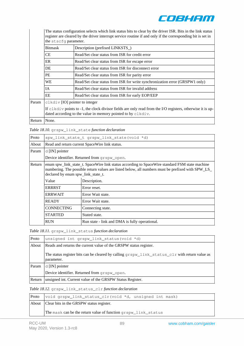
RCC-UMMay 2020, Version 1.3-rc8
89 www.cobham.com/gaisler
The status configuration selects which link status bits to clear by the driver ISR. Bits in the link statusregister are cleared by the driver interrupt service routine if and only if the corresponding bit is set inthe stscfg parameter.
Bitmask Description (prefixed LINKSTS_)
CE Read/Set clear status from ISR for credit error
ER Read/Set clear status from ISR for escape error
DE Read/Set clear status from ISR for disconnect error
PE Read/Set clear status from ISR for parity error
WE Read/Set clear status from ISR for write synchronization error (GRSPW1 only)
IA Read/Set clear status from ISR for invalid address
EE Read/Set clear status from ISR for early EOP/EEP
clkdiv [IO] pointer to integerParam
If clkdiv points to -1, the clock divisor fields are only read from the I/O registers, otherwise it is up-dated according to the value in memory pointed to by clkdiv.
Return None.
Table 18.10. grspw_link_state function declaration
Proto spw_link_state_t grspw_link_state(void *d)
About Read and return current SpaceWire link status.
d [IN] pointerParam
Device identifier. Returned from grspw_open.
enum spw_link_state_t. SpaceWire link status according to SpaceWire standard FSM state machinenumbering. The possible return values are listed below, all numbers must be prefixed with SPW_LS_declared by enum spw_link_state_t.
Value Description.
ERRRST Error reset.
ERRWAIT Error Wait state.
READY Error Wait state.
CONNECTING Connecting state.
STARTED Stated state.
Return
RUN Run state - link and DMA is fully operational.
Table 18.11. grspw_link_status function declaration
Proto unsigned int grspw_link_status(void *d)
About Reads and returns the current value of the GRSPW status register.
The status register bits can be cleared by calling grspw_link_status_clr with return value asparameter.
d [IN] pointerParam
Device identifier. Returned from grspw_open.
Return unsigned int. Current value of the GRSPW Status Register.
Table 18.12. grspw_link_status_clr function declaration
Proto void grspw_link_status_clr(void *d, unsigned int mask)
About Clear bits in the GRSPW status register.
The mask can be the return value of function grspw_link_status
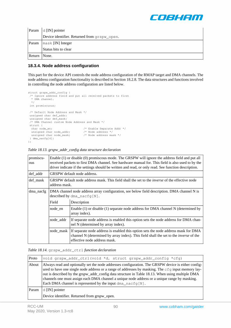
RCC-UMMay 2020, Version 1.3-rc8
90 www.cobham.com/gaisler
d [IN] pointerParam
Device identifier. Returned from grspw_open.
mask [IN] IntegerParam
Status bits to clear
Return None.
18.3.4. Node address configuration
This part for the device API controls the node address configuration of the RMAP target and DMA channels. Thenode address configuration functionality is described in Section 18.2.8. The data structures and functions involvedin controlling the node address configuration are listed below.
struct grspw_addr_config { /* Ignore address field and put all received packets to first * DMA channel. */ int promiscuous;
/* Default Node Address and Mask */ unsigned char def_addr; unsigned char def_mask; /* DMA Channel custom Node Address and Mask */ struct { char node_en; /* Enable Separate Addr */ unsigned char node_addr; /* Node address */ unsigned char node_mask; /* Node address mask */ } dma_nacfg[4];};
Table 18.13. grspw_addr_config data structure declaration
promiscu-ous
Enable (1) or disable (0) promiscous mode. The GRSPW will ignore the address field and put allreceived packets to first DMA channel. See hardware manual for. This field is also used to by thedriver indicate if the settings should be written and read, or only read. See function description.
def_addr GRSPW default node address.
def_mask GRSPW default node address mask. This field shall the set to the inverse of the effective nodeaddress mask.
DMA channel node address array configuration, see below field description. DMA channel N isdescribed by dma_nacfg[N].
Field Description
node_en Enable (1) or disable (1) separate node address for DMA channel N (determined byarray index).
node_addr If separate node address is enabled this option sets the node address for DMA chan-nel N (determined by array index).
dma_nacfg
node_mask If separate node address is enabled this option sets the node address mask for DMAchannel N (determined by array index). This field shall the set to the inverse of theeffective node address mask.
Table 18.14. grspw_addr_ctrl function declaration
Proto void grspw_addr_ctrl(void *d, struct grspw_addr_config *cfg)
About Always read and optionally set the node addresses configuration. The GRSPW device is either config-ured to have one single node address or a range of addresses by masking. The cfg input memory lay-out is described by the grspw_addr_config data structure in Table 18.13. When using multiple DMAchannels one must assign each DMA channel a unique node address or a unique range by masking.Each DMA channel is represented by the input dma_nacfg[N].
d [IN] pointerParam
Device identifier. Returned from grspw_open.
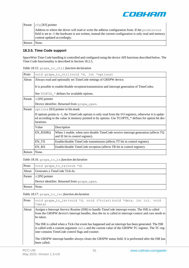
RCC-UMMay 2020, Version 1.3-rc8
91 www.cobham.com/gaisler
cfg [IO] pointerParam
Address to where the driver will read or write the address configuration from. If the promiscousfield is set to -1 the hardware is not written, instead the current configuration is only read and memorycontent updated accordingly.
Return None.
18.3.5. Time Code support
SpaceWire Time Code handling is controlled and configured using the device API functions described below. TheTime Code functionality is described in Section 18.2.5.
Table 18.15. grspw_tc_ctrl function declaration
Proto void grspw_tc_ctrl(void *d, int *options)
About Always read and optionally set TimeCode settings of GRSPW device.
It is possible to enable/disable reception/transmission and interrupt generation of TimeCodes.
See TCOPTS_* defines for available options.
d [IN] pointerParam
Device identifier. Returned from grspw_open.
options [IO] pointer to bit-mask
If options points to -1, the TimeCode options is only read from the I/O registers, otherwise it is updat-ed according to the value in memory pointed to by options. Use TCOPTS_* defines for option bit dec-larations.
Value Description
EN_RXIRQ When 1 enable, when zero disable TimeCode receive interrupt generation (affects TQand IE bit in control register).
EN_TX Enable/disable TimeCode transmission (affects TT bit in control register).
Param
EN_RX Enable/disable TimeCode reception (affects TR bit in control register).
Return None.
Table 18.16. grspw_tc_tx function declaration
Proto void grspw_tc_tx(void *d)
About Generates a TimeCode Tick-In.
d [IN] pointerParam
Device identifier. Returned from grspw_open.
Return None.
Table 18.17. grspw_tc_isr function declaration
Proto void grspw_tc_isr(void *d, void (*tcisr)(void *data, int tc), void*data)
About Assigns a Interrupt Service Routine (ISR) to handle TimeCode interrupt events. The ISR is calledfrom the GRSPW device's interrupt handler, thus the isr is called in interrupt context and care needs tobe taken.
The ISR is called when a Tick-Out event has happened and an interrupt has been generated. The ISRis called with a custom argument data and the current value of the GRSPW TC register. The TC reg-ister contains TimeCode control flags and counter.
The GRSPW interrupt handler always clears the GRSPW status field. It is performed after the ISR hasbeen called.
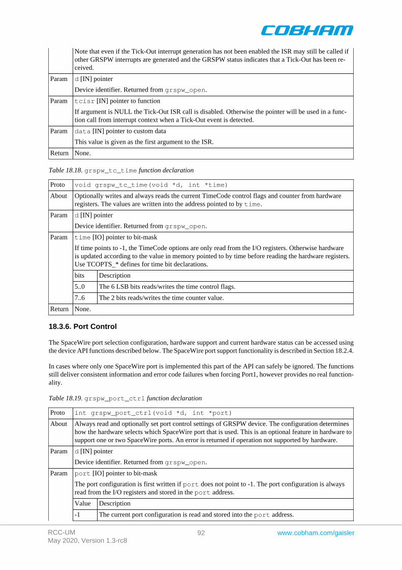
RCC-UMMay 2020, Version 1.3-rc8
92 www.cobham.com/gaisler
Note that even if the Tick-Out interrupt generation has not been enabled the ISR may still be called ifother GRSPW interrupts are generated and the GRSPW status indicates that a Tick-Out has been re-ceived.
d [IN] pointerParam
Device identifier. Returned from grspw_open.
tcisr [IN] pointer to functionParam
If argument is NULL the Tick-Out ISR call is disabled. Otherwise the pointer will be used in a func-tion call from interrupt context when a Tick-Out event is detected.
data [IN] pointer to custom dataParam
This value is given as the first argument to the ISR.
Return None.
Table 18.18. grspw_tc_time function declaration
Proto void grspw_tc_time(void *d, int *time)
About Optionally writes and always reads the current TimeCode control flags and counter from hardwareregisters. The values are written into the address pointed to by time.
d [IN] pointerParam
Device identifier. Returned from grspw_open.
time [IO] pointer to bit-mask
If time points to -1, the TimeCode options are only read from the I/O registers. Otherwise hardwareis updated according to the value in memory pointed to by time before reading the hardware registers.Use TCOPTS_* defines for time bit declarations.
bits Description
5..0 The 6 LSB bits reads/writes the time control flags.
Param
7..6 The 2 bits reads/writes the time counter value.
Return None.
18.3.6. Port Control
The SpaceWire port selection configuration, hardware support and current hardware status can be accessed usingthe device API functions described below. The SpaceWire port support functionality is described in Section 18.2.4.
In cases where only one SpaceWire port is implemented this part of the API can safely be ignored. The functionsstill deliver consistent information and error code failures when forcing Port1, however provides no real function-ality.
Table 18.19. grspw_port_ctrl function declaration
Proto int grspw_port_ctrl(void *d, int *port)
About Always read and optionally set port control settings of GRSPW device. The configuration determineshow the hardware selects which SpaceWire port that is used. This is an optional feature in hardware tosupport one or two SpaceWire ports. An error is returned if operation not supported by hardware.
d [IN] pointerParam
Device identifier. Returned from grspw_open.
port [IO] pointer to bit-mask
The port configuration is first written if port does not point to -1. The port configuration is alwaysread from the I/O registers and stored in the port address.
Value Description
Param
-1 The current port configuration is read and stored into the port address.
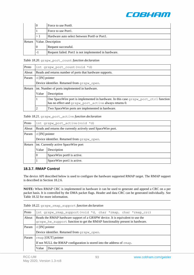
RCC-UMMay 2020, Version 1.3-rc8
93 www.cobham.com/gaisler
0 Force to use Port0.
1 Force to use Port1.
> 1 Hardware auto select between Port0 or Port1.
Value. Description
0 Request successful.
Return
-1 Request failed. Port1 is not implemented in hardware.
Table 18.20. grspw_port_count function declaration
Proto int grspw_port_count(void *d)
About Reads and returns number of ports that hardware supports.
d [IN] pointerParam
Device identifier. Returned from grspw_open.
int. Number of ports implemented in hardware.
Value Description
1 One SpaceWire port is implemented in hardware. In this case grspw_port_ctrl functionhas no effect and grspw_port_active always returns 0.
Return
2 Two SpaceWire ports are implemented in hardware.
Table 18.21. grspw_port_active function declaration
Proto int grspw_port_active(void *d)
About Reads and returns the currently actively used SpaceWire port.
d [IN] pointerParam
Device identifier. Returned from grspw_open.
int. Currently active SpaceWire port
Value Description
0 SpaceWire port0 is active.
Return
1 SpaceWire port1 is active.
18.3.7. RMAP Control
The device API described below is used to configure the hardware supported RMAP target. The RMAP supportis described in Section 18.2.6.
NOTE: When RMAP CRC is implemented in hardware it can be used to generate and append a CRC on a perpacket basis. It is controlled by the DMA packet flags. Header and data CRC can be generated individually. SeeTable 18.32 for more information.
Table 18.22. grspw_rmap_support function declaration
Proto int grspw_rmap_support(void *d, char *rmap, char *rmap_crc)
About Reads the RMAP hardware support of a GRSPW device. It is equivalent to use thegrspw_hw_support function to get the RMAP functionality present in hardware.
d [IN] pointerParam
Device identifier. Returned from grspw_open.
rmap [OUT] pointer
If not NULL the RMAP configuration is stored into the address of rmap.
Param
Value Description
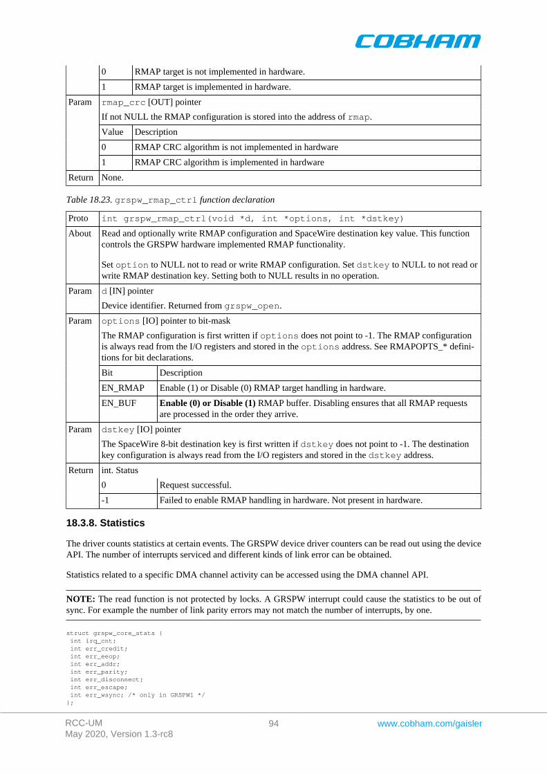
RCC-UMMay 2020, Version 1.3-rc8
94 www.cobham.com/gaisler
0 RMAP target is not implemented in hardware.
1 RMAP target is implemented in hardware.
rmap_crc [OUT] pointer
If not NULL the RMAP configuration is stored into the address of rmap.
Value Description
0 RMAP CRC algorithm is not implemented in hardware
Param
1 RMAP CRC algorithm is implemented in hardware
Return None.
Table 18.23. grspw_rmap_ctrl function declaration
Proto int grspw_rmap_ctrl(void *d, int *options, int *dstkey)
About Read and optionally write RMAP configuration and SpaceWire destination key value. This functioncontrols the GRSPW hardware implemented RMAP functionality.
Set option to NULL not to read or write RMAP configuration. Set dstkey to NULL to not read orwrite RMAP destination key. Setting both to NULL results in no operation.
d [IN] pointerParam
Device identifier. Returned from grspw_open.
options [IO] pointer to bit-mask
The RMAP configuration is first written if options does not point to -1. The RMAP configurationis always read from the I/O registers and stored in the options address. See RMAPOPTS_* defini-tions for bit declarations.
Bit Description
EN_RMAP Enable (1) or Disable (0) RMAP target handling in hardware.
Param
EN_BUF Enable (0) or Disable (1) RMAP buffer. Disabling ensures that all RMAP requestsare processed in the order they arrive.
dstkey [IO] pointerParam
The SpaceWire 8-bit destination key is first written if dstkey does not point to -1. The destinationkey configuration is always read from the I/O registers and stored in the dstkey address.
int. Status
0 Request successful.
Return
-1 Failed to enable RMAP handling in hardware. Not present in hardware.
18.3.8. Statistics
The driver counts statistics at certain events. The GRSPW device driver counters can be read out using the deviceAPI. The number of interrupts serviced and different kinds of link error can be obtained.
Statistics related to a specific DMA channel activity can be accessed using the DMA channel API.
NOTE: The read function is not protected by locks. A GRSPW interrupt could cause the statistics to be out ofsync. For example the number of link parity errors may not match the number of interrupts, by one.
struct grspw_core_stats { int irq_cnt; int err_credit; int err_eeop; int err_addr; int err_parity; int err_disconnect; int err_escape; int err_wsync; /* only in GRSPW1 */};
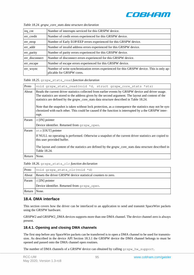
RCC-UMMay 2020, Version 1.3-rc8
95 www.cobham.com/gaisler
Table 18.24. grspw_core_stats data structure declaration
irq_cnt Number of interrupts serviced for this GRSPW device.
err_credit Number of credit errors experienced for this GRSPW device.
err_eeop Number of Early EOP/EEP errors experienced for this GRSPW device.
err_addr Number of invalid address errors experienced for this GRSPW device.
err_parity Number of parity errors experienced for this GRSPW device.
err_disconnect Number of disconnect errors experienced for this GRSPW device.
err_escape Number of escape errors experienced for this GRSPW device.
err_wsync Number of write synchronization errors experienced for this GRSPW device. This is only ap-plicable for GRSPW cores.
Table 18.25. grspw_stats_read function declaration
Proto void grspw_stats_read(void *d, struct grspw_core_stats *sts)
About Reads the current driver statistics collected from earlier events by GRSPW device and driver usage.The statistics are stored to the address given by the second argument. The layout and content of thestatistics are defined by the grspw_core_stats data structure described in Table 18.24.
Note that the snapshot is taken without lock protection, as a consequence the statistics may not be syn-chronized with each other. This could be caused if the function is interrupted by a the GRSPW inter-rupt.
d [IN] pointerParam
Device identifier. Returned from grspw_open.
sts [OUT] pointerParam
If NULL no operating is performed. Otherwise a snapshot of the current driver statistics are copied tothis user provided buffer.
The layout and content of the statistics are defined by the grspw_core_stats data structure described inTable 18.24.
Return None.
Table 18.26. grspw_stats_clr function declaration
Proto void grspw_stats_clr(void *d)
About Resets the driver GRSPW device statistical counters to zero.
d [IN] pointerParam
Device identifier. Returned from grspw_open.
Return None.
18.4. DMA interface
This section covers how the driver can be interfaced to an application to send and transmit SpaceWire packetsusing the GRSPW hardware.
GRSPW2 and GRSPW2_DMA devices supports more than one DMA channel. The device channel zero is alwayspresent.
18.4.1. Opening and closing DMA channels
The first step before any SpaceWire packets can be transferred is to open a DMA channel to be used for transmis-sion. As described in the device API Section 18.3.1 the GRSPW device the DMA channel belongs to must beopened and passed onto the DMA channel open routines.
The number of DMA channels of a GRSPW device can obtained by calling grspw_hw_support.
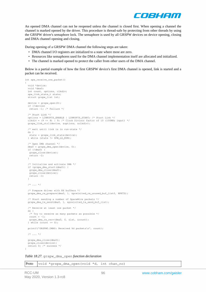
RCC-UMMay 2020, Version 1.3-rc8
96 www.cobham.com/gaisler
An opened DMA channel can not be reopened unless the channel is closed first. When opening a channel thechannel is marked opened by the driver. This procedure is thread-safe by protecting from other threads by usingthe GRSPW driver's semaphore lock. The semaphore is used by all GRSPW devices on device opening, closingand DMA channel opening and closing.
During opening of a GRSPW DMA channel the following steps are taken:
• DMA channel I/O registers are initialized to a state where most are zero.• Resources like semaphores used for the DMA channel implementation itself are allocated and initialized.• The channel is marked opened to protect the caller from other users of the DMA channel.
Below is a partial example of how the first GRSPW device's first DMA channel is opened, link is started and apacket can be received.
int spw_receive_one_packet(){ void *device; void *dma0; int count, options, clkdiv; spw_link_state_t state; struct grspw_list lst;
device = grspw_open(0); if (!device) return -1; /* Failure */
/* Start Link */ options = LINKOPTS_ENABLE | LINKOPTS_START; /* Start Link */ clkdiv = (9 << 8) | 9; /* Clock Divisor factor of 10 (100MHz input) */ grspw_link_ctrl(device, &options, &clkdiv);
/* wait until link is in run-state */ do { state = grspw_link_state(device); } while (state != SPW_LS_RUN);
/* Open DMA channel */ dma0 = grspw_dma_open(device, 0); if (!dma0) { grspw_close(device); return -2; }
/* Initialize and activate DMA */ if (grspw_dma_start(dma0)) { grspw_dma_close(dma0); grspw_close(device); return -3; } /* ... */ /* Prepare driver with RX buffers */ grspw_dma_rx_prepare(dma0, 1, &preinited_rx_unused_buf_list0, NPKTS);
/* Start sending a number of SpaceWire packets */ grspw_dma_tx_send(dma0, 1, &preinited_tx_send_buf_list);
/* Receive at least one packet */ do { /* Try to receive as many packets as possible */ count = -1; grspw_dma_rx_recv(dma0, 0, &lst, &count); } while (count <= 0);
printf("GRSPW0.DMA0: Received %d packets\n", count);
/* ... */
grspw_dma_close(dma0); grspw_close(device); return 0; /* success */}
Table 18.27. grspw_dma_open function declaration
Proto void *grspw_dma_open(void *d, int chan_no)
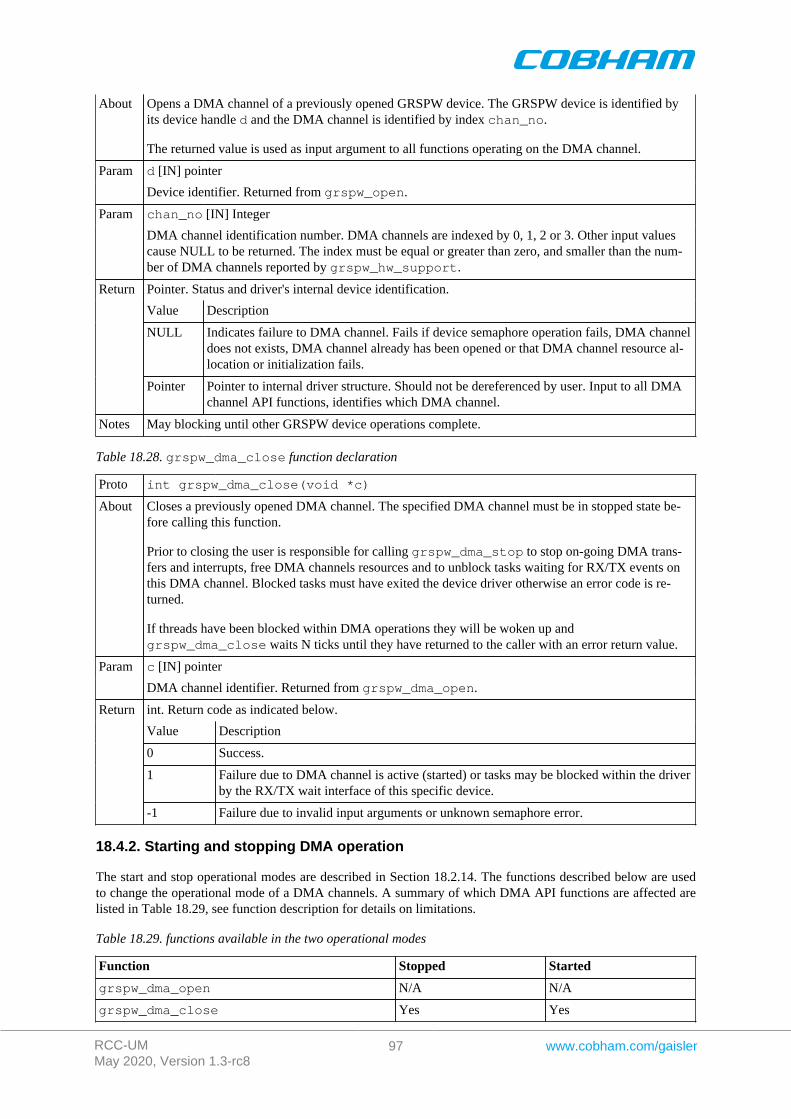
RCC-UMMay 2020, Version 1.3-rc8
97 www.cobham.com/gaisler
About Opens a DMA channel of a previously opened GRSPW device. The GRSPW device is identified byits device handle d and the DMA channel is identified by index chan_no.
The returned value is used as input argument to all functions operating on the DMA channel.
d [IN] pointerParam
Device identifier. Returned from grspw_open.
chan_no [IN] IntegerParam
DMA channel identification number. DMA channels are indexed by 0, 1, 2 or 3. Other input valuescause NULL to be returned. The index must be equal or greater than zero, and smaller than the num-ber of DMA channels reported by grspw_hw_support.
Pointer. Status and driver's internal device identification.
Value Description
NULL Indicates failure to DMA channel. Fails if device semaphore operation fails, DMA channeldoes not exists, DMA channel already has been opened or that DMA channel resource al-location or initialization fails.
Return
Pointer Pointer to internal driver structure. Should not be dereferenced by user. Input to all DMAchannel API functions, identifies which DMA channel.
Notes May blocking until other GRSPW device operations complete.
Table 18.28. grspw_dma_close function declaration
Proto int grspw_dma_close(void *c)
About Closes a previously opened DMA channel. The specified DMA channel must be in stopped state be-fore calling this function.
Prior to closing the user is responsible for calling grspw_dma_stop to stop on-going DMA trans-fers and interrupts, free DMA channels resources and to unblock tasks waiting for RX/TX events onthis DMA channel. Blocked tasks must have exited the device driver otherwise an error code is re-turned.
If threads have been blocked within DMA operations they will be woken up andgrspw_dma_close waits N ticks until they have returned to the caller with an error return value.
c [IN] pointerParam
DMA channel identifier. Returned from grspw_dma_open.
int. Return code as indicated below.
Value Description
0 Success.
1 Failure due to DMA channel is active (started) or tasks may be blocked within the driverby the RX/TX wait interface of this specific device.
Return
-1 Failure due to invalid input arguments or unknown semaphore error.
18.4.2. Starting and stopping DMA operation
The start and stop operational modes are described in Section 18.2.14. The functions described below are usedto change the operational mode of a DMA channels. A summary of which DMA API functions are affected arelisted in Table 18.29, see function description for details on limitations.
Table 18.29. functions available in the two operational modes
Function Stopped Started
grspw_dma_open N/A N/A
grspw_dma_close Yes Yes
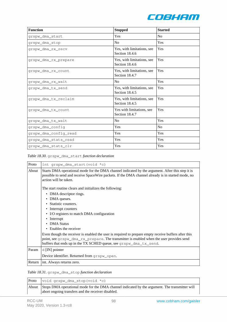
RCC-UMMay 2020, Version 1.3-rc8
98 www.cobham.com/gaisler
Function Stopped Started
grspw_dma_start Yes No
grspw_dma_stop No Yes
grspw_dma_rx_recv Yes, with limitations, seeSection 18.4.6
Yes
grspw_dma_rx_prepare Yes, with limitations, seeSection 18.4.6
Yes
grspw_dma_rx_count Yes, with limitations, seeSection 18.4.7
Yes
grspw_dma_rx_wait No Yes
grspw_dma_tx_send Yes, with limitations, seeSection 18.4.5
Yes
grspw_dma_tx_reclaim Yes, with limitations, seeSection 18.4.5
Yes
grspw_dma_tx_count Yes with limitations, seeSection 18.4.7
Yes
grspw_dma_tx_wait No Yes
grspw_dma_config Yes No
grspw_dma_config_read Yes Yes
grspw_dma_stats_read Yes Yes
grspw_dma_stats_clr Yes Yes
Table 18.30. grspw_dma_start function declaration
Proto int grspw_dma_start(void *c)
About Starts DMA operational mode for the DMA channel indicated by the argument. After this step it ispossible to send and receive SpaceWire packets. If the DMA channel already is in started mode, noaction will be taken.
The start routine clears and initializes the following:
• DMA descriptor rings.• DMA queues.• Statistic counters.• Interrupt counters• I/O registers to match DMA configuration• Interrupt• DMA Status• Enables the receiver
Even though the receiver is enabled the user is required to prepare empty receive buffers after thispoint, see grspw_dma_rx_prepare. The transmitter is enabled when the user provides sendbuffers that ends up in the TX SCHED queue, see grspw_dma_tx_send.
d [IN] pointerParam
Device identifier. Returned from grspw_open.
Return int. Always returns zero.
Table 18.31. grspw_dma_stop function declaration
Proto void grspw_dma_stop(void *c)
About Stops DMA operational mode for the DMA channel indicated by the argument. The transmitter willabort ongoing transfers and the receiver disabled.
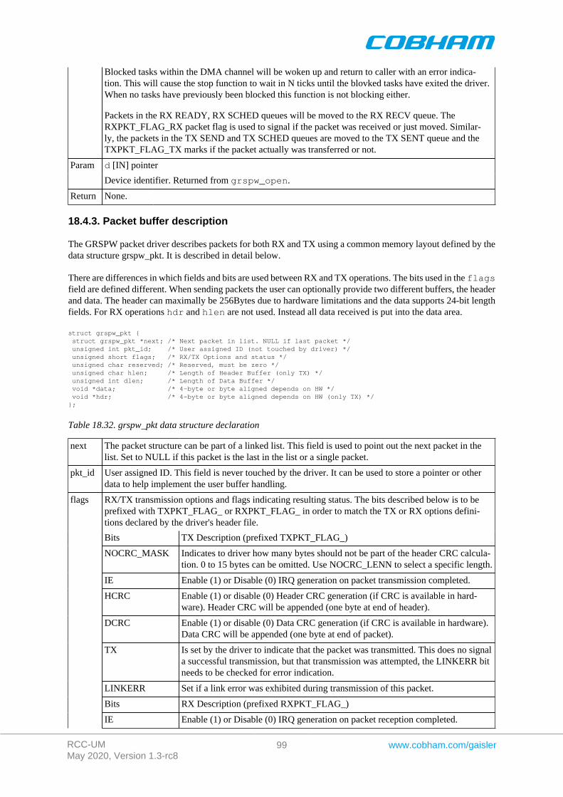
RCC-UMMay 2020, Version 1.3-rc8
99 www.cobham.com/gaisler
Blocked tasks within the DMA channel will be woken up and return to caller with an error indica-tion. This will cause the stop function to wait in N ticks until the blovked tasks have exited the driver.When no tasks have previously been blocked this function is not blocking either.
Packets in the RX READY, RX SCHED queues will be moved to the RX RECV queue. TheRXPKT_FLAG_RX packet flag is used to signal if the packet was received or just moved. Similar-ly, the packets in the TX SEND and TX SCHED queues are moved to the TX SENT queue and theTXPKT_FLAG_TX marks if the packet actually was transferred or not.
d [IN] pointerParam
Device identifier. Returned from grspw_open.
Return None.
18.4.3. Packet buffer description
The GRSPW packet driver describes packets for both RX and TX using a common memory layout defined by thedata structure grspw_pkt. It is described in detail below.
There are differences in which fields and bits are used between RX and TX operations. The bits used in the flagsfield are defined different. When sending packets the user can optionally provide two different buffers, the headerand data. The header can maximally be 256Bytes due to hardware limitations and the data supports 24-bit lengthfields. For RX operations hdr and hlen are not used. Instead all data received is put into the data area.
struct grspw_pkt { struct grspw_pkt *next; /* Next packet in list. NULL if last packet */ unsigned int pkt_id; /* User assigned ID (not touched by driver) */ unsigned short flags; /* RX/TX Options and status */ unsigned char reserved; /* Reserved, must be zero */ unsigned char hlen; /* Length of Header Buffer (only TX) */ unsigned int dlen; /* Length of Data Buffer */ void *data; /* 4-byte or byte aligned depends on HW */ void *hdr; /* 4-byte or byte aligned depends on HW (only TX) */};
Table 18.32. grspw_pkt data structure declaration
next The packet structure can be part of a linked list. This field is used to point out the next packet in thelist. Set to NULL if this packet is the last in the list or a single packet.
pkt_id User assigned ID. This field is never touched by the driver. It can be used to store a pointer or otherdata to help implement the user buffer handling.
RX/TX transmission options and flags indicating resulting status. The bits described below is to beprefixed with TXPKT_FLAG_ or RXPKT_FLAG_ in order to match the TX or RX options defini-tions declared by the driver's header file.
Bits TX Description (prefixed TXPKT_FLAG_)
NOCRC_MASK Indicates to driver how many bytes should not be part of the header CRC calcula-tion. 0 to 15 bytes can be omitted. Use NOCRC_LENN to select a specific length.
IE Enable (1) or Disable (0) IRQ generation on packet transmission completed.
HCRC Enable (1) or disable (0) Header CRC generation (if CRC is available in hard-ware). Header CRC will be appended (one byte at end of header).
DCRC Enable (1) or disable (0) Data CRC generation (if CRC is available in hardware).Data CRC will be appended (one byte at end of packet).
TX Is set by the driver to indicate that the packet was transmitted. This does no signala successful transmission, but that transmission was attempted, the LINKERR bitneeds to be checked for error indication.
LINKERR Set if a link error was exhibited during transmission of this packet.
Bits RX Description (prefixed RXPKT_FLAG_)
flags
IE Enable (1) or Disable (0) IRQ generation on packet reception completed.

RCC-UMMay 2020, Version 1.3-rc8
100 www.cobham.com/gaisler
TRUNK Set if packet was truncated.
DCRC Set if data CRC error detected (only valid if RMAP CRC is enabled).
HCRC Set if header CRC error detected (only valid if RMAP CRC is enabled).
EEOP Set if an End-of-Packet error occurred during reception of this packet.
RX Marks if packet was received or not.
hlen Header length. The number of bytes hardware will transfer using DMA from the address indicated bythe hdr pointer. This field is not used by RX operation.
dlen Data payload length. The number of bytes hardware DMA read or written from/to the address indicat-ed by the data pointer. On RX this is the complete packet data received.
data Header Buffer Address. DMA will read from this. The address can be 4-byte or byte aligned depend-ing on hardware.
hdr Header Buffer Address. DMA will read hlen bytes from this. The address can be 4-byte or bytealigned depending on hardware. This field is not used by RX operation.
18.4.4. Blocking/Waiting on DMA activity
Blocking and polling mode are described in the Section 18.2.12. The functions described below are used to set upRX or TX wait conditions and blocks the calling thread until condition evaluates true.
Table 18.33. grspw_dma_tx_wait function declaration
Proto int grspw_dma_tx_wait(void *c, int send_cnt, int op, int sent_cnt,int timeout)
About Block until send_cnt or fewer packets are queued in TX "Send and Scheduled" queue, op (AND orOR), sent_cnt or more packet "have been sent" (Sent Q) condition is met.
If a link error occurs and the "Disable on Link error" is defined, this function will also return to caller.The timeout argument is used to return after timeout ticks, regardless of the other conditions. Iftimeout is zero, the function will wait forever until the condition is satisfied.
NOTE: If IRQ of TX descriptors are not enabled conditions are never checked, this may hang in-finitely unless a timeout has been specified.
d [IN] pointerParam
Device identifier. Returned from grspw_open.
send_cnt [IN] intParam
Sets the condition's number of packets in TX SEND queue.
op [IN] booleanParam
Condition operation. Set to zero for AND or one for OR.
sent_cnt [IN] intParam
Sets the condition's number of packets in TX SENT queue.
timeout [IN] intParam
Sets the timeout in number of system clock ticks. The operating system's semaphore service is used toimplement the timeout functionality. Set to zero to disable timeout, negative value is invalid.
Int. See return code below.
Value Description
-1 Error.
0 Returning to caller because specified conditions are now fullfilled.
1 DMA stopped.
Return
2 Timeout, conditions are not met.
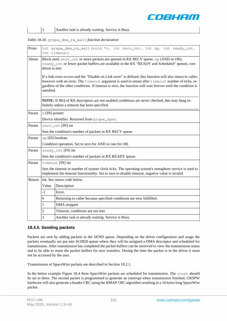
RCC-UMMay 2020, Version 1.3-rc8
101 www.cobham.com/gaisler
3 Another task is already waiting. Service is Busy.
Table 18.34. grspw_dma_rx_wait function declaration
Proto int grspw_dma_rx_wait(void *c, int recv_cnt, int op, int ready_cnt,int timeout)
About Block until recv_cnt or more packets are queued in RX RECV queue, op (AND or OR),ready_cnt or fewer packet buffers are available in the RX "READY and Scheduled" queues, con-dition is met.
If a link error occurs and the "Disable on Link error" is defined, this function will also return to caller,however with an error. The timeout argument is used to return after timeout number of ticks, re-gardless of the other conditions. If timeout is zero, the function will wait forever until the condition issatisfied.
NOTE: If IRQ of RX descriptors are not enabled conditions are never checked, this may hang in-finitely unless a timeout has been specified.
d [IN] pointerParam
Device identifier. Returned from grspw_open.
recv_cnt [IN] intParam
Sets the condition's number of packets in RX RECV queue.
op [IN] booleanParam
Condition operation. Set to zero for AND or one for OR.
ready_cnt [IN] intParam
Sets the condition's number of packets in RX READY queue.
timeout [IN] intParam
Sets the timeout in number of system clock ticks. The operating system's semaphore service is used toimplement the timeout functionality. Set to zero to disable timeout, negative value is invalid.
Int. See return code below.
Value Description
-1 Error.
0 Returning to caller because specified conditions are now fullfilled.
1 DMA stopped.
2 Timeout, conditions are not met.
Return
3 Another task is already waiting. Service is Busy.
18.4.5. Sending packets
Packets are sent by adding packets to the SEND queue. Depending on the driver configuration and usage thepackets eventually are put into SCHED queue where they will be assigned a DMA descriptor and scheduled fortransmission. After transmission has completed the packet buffers can be retrieved to view the transmission statusand to be able to reuse the packet buffers for new transfers. During the time the packet is in the driver it mustnot be accessed by the user.
Transmission of SpaceWire packets are described in Section 18.2.1.
In the below example Figure 18.4 three SpaceWire packets are scheduled for transmission. The count shouldbe set to three. The second packet is programmed to generate an interrupt when transmission finished, GRSPWhardware will also generate a header CRC using the RMAP CRC algorithm resulting in a 16 bytes long SpaceWirepacket.
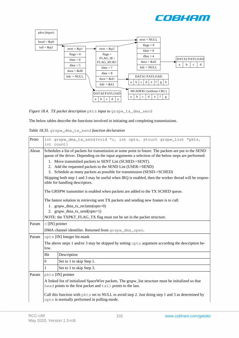
RCC-UMMay 2020, Version 1.3-rc8
102 www.cobham.com/gaisler
pkts (input)
head = &p0
tail = &p2 next = &p1
flags = 0
hlen = 0
dlen = 5
data = &d0
hdr = NULL
next = NULL
flags = 0
hlen = 0
dlen = 4
data = &d2
hdr = NULL
next = &p2
flags =FLAG_IE |
FLAG_HCRC
hlen = 7
dlen = 8
data = &d1
hdr = &h1
DATA0 PAYLOAD
a b c d e
HEADER1 (without CRC)
a b c d e f g
DATA1 PAYLOAD
a b c d e f g h
DATA2 PAYLOAD
a b c d
Figure 18.4. TX packet description pkts input to grspw_tx_dma_send
The below tables describe the functions involved in initiating and completing transmissions.
Table 18.35. grspw_dma_tx_send function declaration
Proto int grspw_dma_tx_send(void *c, int opts, struct grspw_list *pkts,int count)
About Schedules a list of packets for transmission at some point in future. The packets are put to the SENDqueue of the driver. Depending on the input arguments a selection of the below steps are performed:
1. Move transmitted packets to SENT List (SCHED->SENT).2. Add the requested packets to the SEND List (USER->SEND)3. Schedule as many packets as possible for transmission (SEND->SCHED)
Skipping both step 1 and 3 may be useful when IRQ is enabled, then the worker thread will be respon-sible for handling descriptors.
The GRSPW transmitter is enabled when packets are added to the TX SCHED queue.
The fastest solution in retrieving sent TX packets and sending new frames is to call:
1. grspw_dma_tx_reclaim(opts=0)2. grspw_dma_tx_send(opts=1)
NOTE: the TXPKT_FLAG_TX flag must not be set in the packet structure.
c [IN] pointerParam
DMA channel identifier. Returned from grspw_dma_open.
opts [IN] Integer bit-mask
The above steps 1 and/or 3 may be skipped by setting opts argument according the description be-low.
Bit Description
0 Set to 1 to skip Step 1.
Param
1 Set to 1 to skip Step 3.
pkts [IN] pointerParam
A linked list of initialized SpaceWire packets. The grspw_list structure must be initialized so thathead points to the first packet and tail points to the last.
Call this function with pkts set to NULL to avoid step 2. Just doing step 1 and 3 as determined byopts is normally performed in polling-mode.
RCC-UMMay 2020, Version 1.3-rc8
103 www.cobham.com/gaisler
The layout and content of the packet is defined by the grspw_pkt data structure is described in Ta-ble 18.32. Note that TXPKT_FLAG_TX of the flags field must not be set.
pkts is not cleared by this function.
count [IN] integerParam
Number of packets in the packet list.
Status. See return codes below
Value Description
-1 Error occurred, DMA channel may not be valid.
0 Successfully added pkts to TX SEND/SCHED list.
Return
1 DMA stopped. No operation.
Notes This function performs no operation when the DMA channel is stopped.
Table 18.36. grspw_dma_tx_reclaim function declaration
Proto int grspw_dma_tx_reclaim(void *c, int opts, struct grspw_list *pkts,int *count)
About Reclaim TX packet buffers that has previously been scheduled for transmission withgrspw_dma_tx_send. The packets in the SENT queue are moved to the pkts packet list. Whenthe move has been completed the packet can safely be reused again by the user. The packet structureshave been updated with transmission status to indicate transfer failures of individual packets. Depend-ing on the input arguments a selection of the below steps are performed:
1. Move transmitted packets to SENT List (SCHED->SENT).2. Move all SENT List to pkts list (SENT->USER).3. Schedule as many packets as possible for transmission (SEND->SCHED)
Skipping both step 1 and 3 may be useful when IRQ is enabled, then the worker thread will be respon-sible for descriptor processing. Skipping only step 2 can be useful in polling mode.
The fastest solution in retrieving sent TX packets and sending new frames is to call:
1. grspw_dma_tx_reclaim(opts=0)2. grspw_dma_tx_send(opts=1)
NOTE: the TXPKT_FLAG_TX flag indicates if the packet was transmitted.
c [IN] pointerParam
DMA channel identifier. Returned from grspw_dma_open.
opts [IN] Integer bit-mask
The above steps 1 and/or 3 may be skipped by setting opts argument according the description be-low.
Bit Description
0 Set to 1 to skip Step 1.
Param
1 Set to 1 to skip Step 3.
pkts [OUT] pointerParam
The list will be initialized to contain the SpaceWire packets moved from the SENT queue to the pack-et list. The grspw_list structure will be initialized so that head points to the first packet, tail pointsto the last and the last packet (tail) next pointer is NULL.
Call this function with pkts set to NULL to avoid step 2. Just doing step 1 and 3 as determined byopts is normally performed in polling-mode.
The layout and content of the packet is defined by the grspw_pkt data structure is described in Ta-ble 18.32. Note that TXPKT_FLAG_TX of the flags field indicates if the packet was sent of not.In case of DMA being stopped one can use this flag to see if the packet was transmitted or not. The
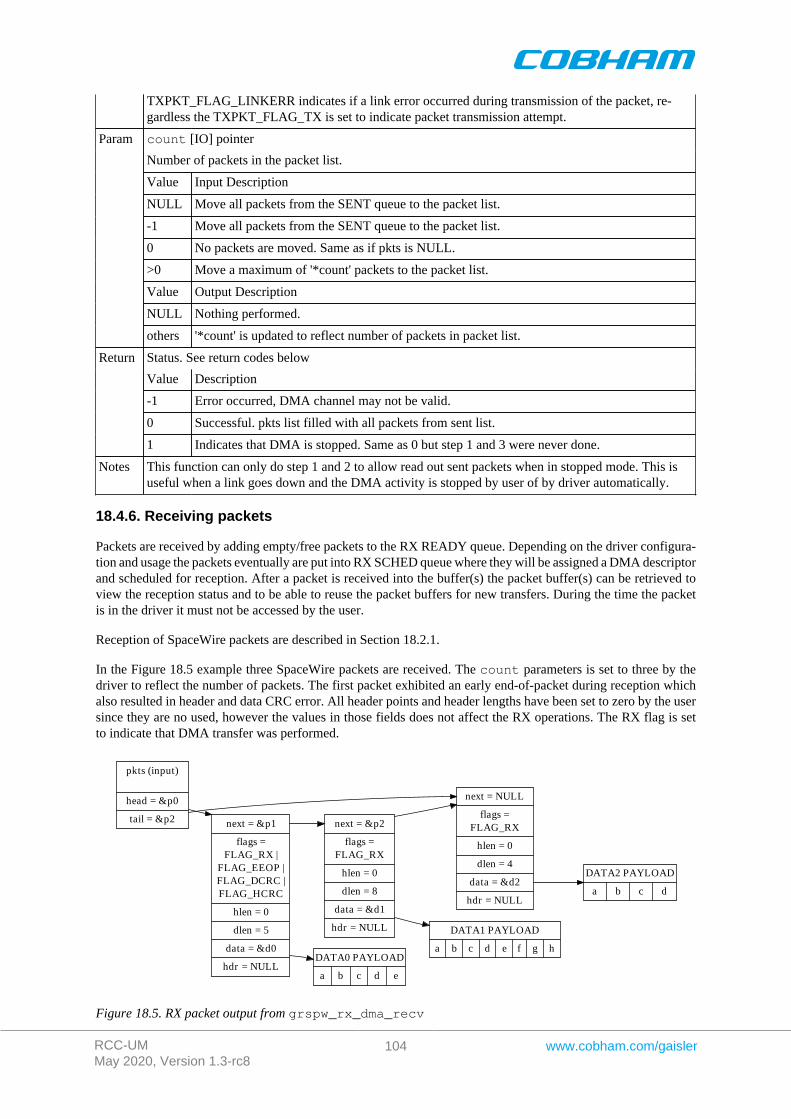
RCC-UMMay 2020, Version 1.3-rc8
104 www.cobham.com/gaisler
TXPKT_FLAG_LINKERR indicates if a link error occurred during transmission of the packet, re-gardless the TXPKT_FLAG_TX is set to indicate packet transmission attempt.
count [IO] pointer
Number of packets in the packet list.
Value Input Description
NULL Move all packets from the SENT queue to the packet list.
-1 Move all packets from the SENT queue to the packet list.
0 No packets are moved. Same as if pkts is NULL.
>0 Move a maximum of '*count' packets to the packet list.
Value Output Description
NULL Nothing performed.
Param
others '*count' is updated to reflect number of packets in packet list.
Status. See return codes below
Value Description
-1 Error occurred, DMA channel may not be valid.
0 Successful. pkts list filled with all packets from sent list.
Return
1 Indicates that DMA is stopped. Same as 0 but step 1 and 3 were never done.
Notes This function can only do step 1 and 2 to allow read out sent packets when in stopped mode. This isuseful when a link goes down and the DMA activity is stopped by user of by driver automatically.
18.4.6. Receiving packets
Packets are received by adding empty/free packets to the RX READY queue. Depending on the driver configura-tion and usage the packets eventually are put into RX SCHED queue where they will be assigned a DMA descriptorand scheduled for reception. After a packet is received into the buffer(s) the packet buffer(s) can be retrieved toview the reception status and to be able to reuse the packet buffers for new transfers. During the time the packetis in the driver it must not be accessed by the user.
Reception of SpaceWire packets are described in Section 18.2.1.
In the Figure 18.5 example three SpaceWire packets are received. The count parameters is set to three by thedriver to reflect the number of packets. The first packet exhibited an early end-of-packet during reception whichalso resulted in header and data CRC error. All header points and header lengths have been set to zero by the usersince they are no used, however the values in those fields does not affect the RX operations. The RX flag is setto indicate that DMA transfer was performed.
pkts (input)
head = &p0
tail = &p2 next = &p1
flags =FLAG_RX |
FLAG_EEOP |FLAG_DCRC |FLAG_HCRC
hlen = 0
dlen = 5
data = &d0
hdr = NULL
next = NULL
flags =FLAG_RX
hlen = 0
dlen = 4
data = &d2
hdr = NULL
next = &p2
flags =FLAG_RX
hlen = 0
dlen = 8
data = &d1
hdr = NULL
DATA0 PAYLOAD
a b c d e
DATA1 PAYLOAD
a b c d e f g h
DATA2 PAYLOAD
a b c d
Figure 18.5. RX packet output from grspw_rx_dma_recv
RCC-UMMay 2020, Version 1.3-rc8
105 www.cobham.com/gaisler
The below tables describe the functions involved in initiating and completing transmissions.
Table 18.37. grspw_dma_rx_prepare function declaration
Proto int grspw_dma_rx_prepare(void *c, int opts, struct grspw_list *pkts,int count)
About Add more RX packet buffers for future for reception. The received packets can later be read out withgrspw_dma_rx_recv. The packets are put to the READY queue of the driver. Depending on theinput arguments a selection of the below steps are performed:
1. Move Received packets to RECV List (SCHED->RECV).2. Add the pkt packet buffers to the READY List (USER->READY).3. Schedule as many packets as possible (READY->SCHED).
Skipping both step 1 and 3 may be useful when IRQ is enabled, then the worker thread will be respon-sible for handling descriptors. Skipping only step 2 can be useful in polling mode.
The fastest solution in retrieving received RX packets and preparing new packet buffers for future re-ceive, is to call:
1. grspw_dma_rx_recv(opts=2, &recvlist) (Skip step 3)2. grspw_dma_rx_prepare(opts=1, &freelist) (Skip step 1)
NOTE: the RXPKT_FLAG_RX flag must not be set in the packet structure.
c [IN] pointerParam
DMA channel identifier. Returned from grspw_dma_open.
opts [IN] Integer bit-mask
The above steps 1 and/or 3 may be skipped by setting opts argument according the description be-low.
Bit Description
0 Set to 1 to skip Step 1.
Param
1 Set to 1 to skip Step 3.
pkts [IN] pointerParam
A linked list of initialized SpaceWire packets. The grspw_list structure must be initialized so thathead points to the first packet and tail points to the last.
Call this function with pkts set to NULL to avoid step 2. Just doing step 1 and 3 as determined byopts is normally performed in polling-mode.
The layout and content of the packet is defined by the grspw_pkt data structure is described in Ta-ble 18.32. Note that RXPKT_FLAG_RX of the flags field must not be set.
pkts is not cleared by this function.
count [IN] integerParam
Number of packets in the packet list.
Status. See return codes below
Value Description
-1 Error occurred, DMA channel may not be valid.
0 Successfully added pkts to RX READY/SCHED list.
Return
1 DMA stopped. No operation.
Notes This function performs no operation when the DMA channel is stopped.
Table 18.38. grspw_dma_rx_recv function declaration
Proto int grspw_dma_rx_recv(void *c, int opts, struct grspw_list *pkts,int *count)
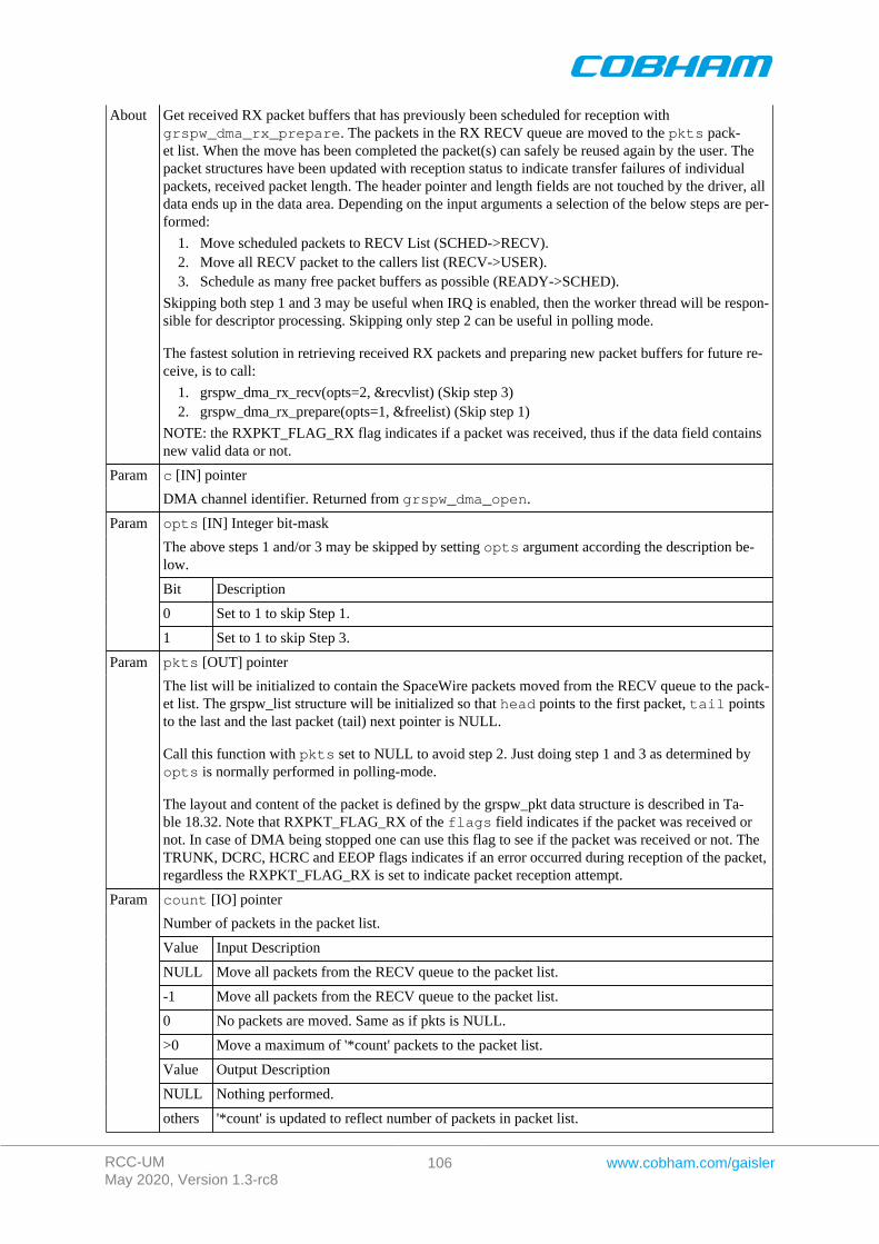
RCC-UMMay 2020, Version 1.3-rc8
106 www.cobham.com/gaisler
About Get received RX packet buffers that has previously been scheduled for reception withgrspw_dma_rx_prepare. The packets in the RX RECV queue are moved to the pkts pack-et list. When the move has been completed the packet(s) can safely be reused again by the user. Thepacket structures have been updated with reception status to indicate transfer failures of individualpackets, received packet length. The header pointer and length fields are not touched by the driver, alldata ends up in the data area. Depending on the input arguments a selection of the below steps are per-formed:
1. Move scheduled packets to RECV List (SCHED->RECV).2. Move all RECV packet to the callers list (RECV->USER).3. Schedule as many free packet buffers as possible (READY->SCHED).
Skipping both step 1 and 3 may be useful when IRQ is enabled, then the worker thread will be respon-sible for descriptor processing. Skipping only step 2 can be useful in polling mode.
The fastest solution in retrieving received RX packets and preparing new packet buffers for future re-ceive, is to call:
1. grspw_dma_rx_recv(opts=2, &recvlist) (Skip step 3)2. grspw_dma_rx_prepare(opts=1, &freelist) (Skip step 1)
NOTE: the RXPKT_FLAG_RX flag indicates if a packet was received, thus if the data field containsnew valid data or not.
c [IN] pointerParam
DMA channel identifier. Returned from grspw_dma_open.
opts [IN] Integer bit-mask
The above steps 1 and/or 3 may be skipped by setting opts argument according the description be-low.
Bit Description
0 Set to 1 to skip Step 1.
Param
1 Set to 1 to skip Step 3.
pkts [OUT] pointerParam
The list will be initialized to contain the SpaceWire packets moved from the RECV queue to the pack-et list. The grspw_list structure will be initialized so that head points to the first packet, tail pointsto the last and the last packet (tail) next pointer is NULL.
Call this function with pkts set to NULL to avoid step 2. Just doing step 1 and 3 as determined byopts is normally performed in polling-mode.
The layout and content of the packet is defined by the grspw_pkt data structure is described in Ta-ble 18.32. Note that RXPKT_FLAG_RX of the flags field indicates if the packet was received ornot. In case of DMA being stopped one can use this flag to see if the packet was received or not. TheTRUNK, DCRC, HCRC and EEOP flags indicates if an error occurred during reception of the packet,regardless the RXPKT_FLAG_RX is set to indicate packet reception attempt.
count [IO] pointer
Number of packets in the packet list.
Value Input Description
NULL Move all packets from the RECV queue to the packet list.
-1 Move all packets from the RECV queue to the packet list.
0 No packets are moved. Same as if pkts is NULL.
>0 Move a maximum of '*count' packets to the packet list.
Value Output Description
NULL Nothing performed.
Param
others '*count' is updated to reflect number of packets in packet list.
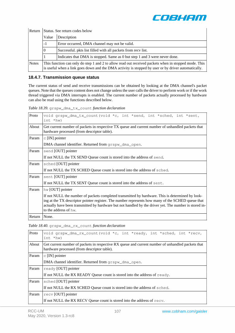
RCC-UMMay 2020, Version 1.3-rc8
107 www.cobham.com/gaisler
Status. See return codes below
Value Description
-1 Error occurred, DMA channel may not be valid.
0 Successful. pkts list filled with all packets from recv list.
Return
1 Indicates that DMA is stopped. Same as 0 but step 1 and 3 were never done.
Notes This function can only do step 1 and 2 to allow read out received packets when in stopped mode. Thisis useful when a link goes down and the DMA activity is stopped by user or by driver automatically.
18.4.7. Transmission queue status
The current status of send and receive transmissions can be obtained by looking at the DMA channel's packetqueues. Note that the queues content does not change unless the user calls the driver to perform work or if the workthread triggered via DMA interrupts is enabled. The current number of packets actually processed by hardwarecan also be read using the functions described below.
Table 18.39. grspw_dma_tx_count function declaration
Proto void grspw_dma_tx_count(void *c, int *send, int *sched, int *sent,int *hw)
About Get current number of packets in respective TX queue and current number of unhandled packets thathardware processed (from descriptor table).
c [IN] pointerParam
DMA channel identifier. Returned from grspw_dma_open.
send [OUT] pointerParam
If not NULL the TX SEND Queue count is stored into the address of send.
sched [OUT] pointerParam
If not NULL the TX SCHED Queue count is stored into the address of sched.
sent [OUT] pointerParam
If not NULL the TX SENT Queue count is stored into the address of sent.
hw [OUT] pointerParam
If not NULL the number of packets completed transmitted by hardware. This is determined by look-ing at the TX descriptor pointer register. The number represents how many of the SCHED queue thatactually have been transmitted by hardware but not handled by the driver yet. The number is stored in-to the address of hw.
Return None.
Table 18.40. grspw_dma_rx_count function declaration
Proto void grspw_dma_rx_count(void *c, int *ready, int *sched, int *recv,int *hw)
About Get current number of packets in respective RX queue and current number of unhandled packets thathardware processed (from descriptor table).
c [IN] pointerParam
DMA channel identifier. Returned from grspw_dma_open.
ready [OUT] pointerParam
If not NULL the RX READY Queue count is stored into the address of ready.
sched [OUT] pointerParam
If not NULL the RX SCHED Queue count is stored into the address of sched.
recv [OUT] pointerParam
If not NULL the RX RECV Queue count is stored into the address of recv.
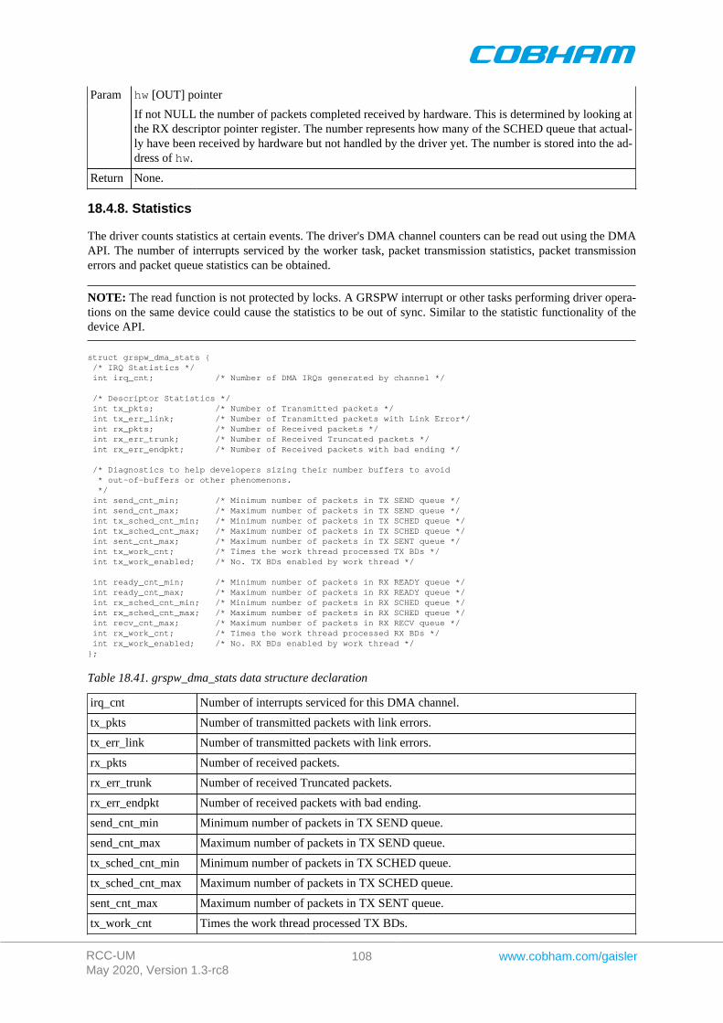
RCC-UMMay 2020, Version 1.3-rc8
108 www.cobham.com/gaisler
hw [OUT] pointerParam
If not NULL the number of packets completed received by hardware. This is determined by looking atthe RX descriptor pointer register. The number represents how many of the SCHED queue that actual-ly have been received by hardware but not handled by the driver yet. The number is stored into the ad-dress of hw.
Return None.
18.4.8. Statistics
The driver counts statistics at certain events. The driver's DMA channel counters can be read out using the DMAAPI. The number of interrupts serviced by the worker task, packet transmission statistics, packet transmissionerrors and packet queue statistics can be obtained.
NOTE: The read function is not protected by locks. A GRSPW interrupt or other tasks performing driver opera-tions on the same device could cause the statistics to be out of sync. Similar to the statistic functionality of thedevice API.
struct grspw_dma_stats { /* IRQ Statistics */ int irq_cnt; /* Number of DMA IRQs generated by channel */
/* Descriptor Statistics */ int tx_pkts; /* Number of Transmitted packets */ int tx_err_link; /* Number of Transmitted packets with Link Error*/ int rx_pkts; /* Number of Received packets */ int rx_err_trunk; /* Number of Received Truncated packets */ int rx_err_endpkt; /* Number of Received packets with bad ending */
/* Diagnostics to help developers sizing their number buffers to avoid * out-of-buffers or other phenomenons. */ int send_cnt_min; /* Minimum number of packets in TX SEND queue */ int send_cnt_max; /* Maximum number of packets in TX SEND queue */ int tx_sched_cnt_min; /* Minimum number of packets in TX SCHED queue */ int tx_sched_cnt_max; /* Maximum number of packets in TX SCHED queue */ int sent_cnt_max; /* Maximum number of packets in TX SENT queue */ int tx_work_cnt; /* Times the work thread processed TX BDs */ int tx_work_enabled; /* No. TX BDs enabled by work thread */
int ready_cnt_min; /* Minimum number of packets in RX READY queue */ int ready_cnt_max; /* Maximum number of packets in RX READY queue */ int rx_sched_cnt_min; /* Minimum number of packets in RX SCHED queue */ int rx_sched_cnt_max; /* Maximum number of packets in RX SCHED queue */ int recv_cnt_max; /* Maximum number of packets in RX RECV queue */ int rx_work_cnt; /* Times the work thread processed RX BDs */ int rx_work_enabled; /* No. RX BDs enabled by work thread */};
Table 18.41. grspw_dma_stats data structure declaration
irq_cnt Number of interrupts serviced for this DMA channel.
tx_pkts Number of transmitted packets with link errors.
tx_err_link Number of transmitted packets with link errors.
rx_pkts Number of received packets.
rx_err_trunk Number of received Truncated packets.
rx_err_endpkt Number of received packets with bad ending.
send_cnt_min Minimum number of packets in TX SEND queue.
send_cnt_max Maximum number of packets in TX SEND queue.
tx_sched_cnt_min Minimum number of packets in TX SCHED queue.
tx_sched_cnt_max Maximum number of packets in TX SCHED queue.
sent_cnt_max Maximum number of packets in TX SENT queue.
tx_work_cnt Times the work thread processed TX BDs.
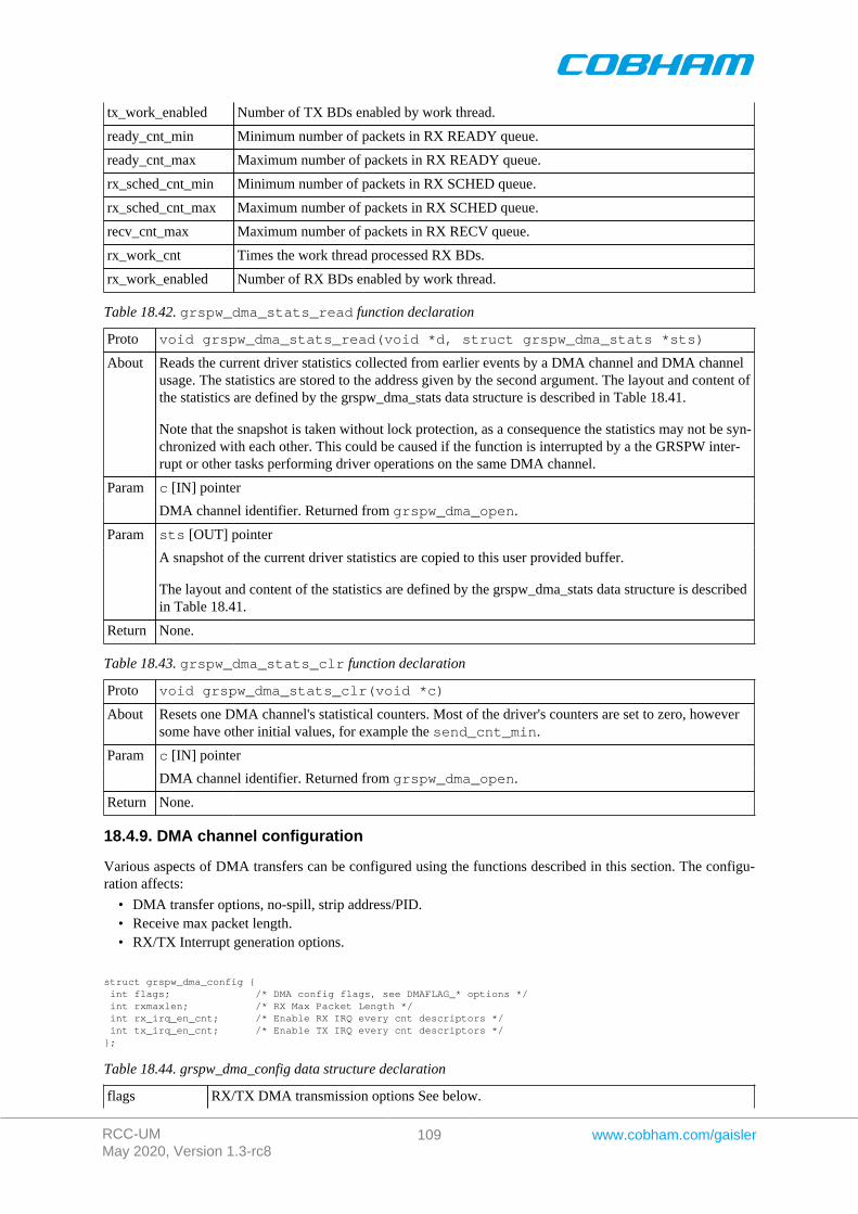
RCC-UMMay 2020, Version 1.3-rc8
109 www.cobham.com/gaisler
tx_work_enabled Number of TX BDs enabled by work thread.
ready_cnt_min Minimum number of packets in RX READY queue.
ready_cnt_max Maximum number of packets in RX READY queue.
rx_sched_cnt_min Minimum number of packets in RX SCHED queue.
rx_sched_cnt_max Maximum number of packets in RX SCHED queue.
recv_cnt_max Maximum number of packets in RX RECV queue.
rx_work_cnt Times the work thread processed RX BDs.
rx_work_enabled Number of RX BDs enabled by work thread.
Table 18.42. grspw_dma_stats_read function declaration
Proto void grspw_dma_stats_read(void *d, struct grspw_dma_stats *sts)
About Reads the current driver statistics collected from earlier events by a DMA channel and DMA channelusage. The statistics are stored to the address given by the second argument. The layout and content ofthe statistics are defined by the grspw_dma_stats data structure is described in Table 18.41.
Note that the snapshot is taken without lock protection, as a consequence the statistics may not be syn-chronized with each other. This could be caused if the function is interrupted by a the GRSPW inter-rupt or other tasks performing driver operations on the same DMA channel.
c [IN] pointerParam
DMA channel identifier. Returned from grspw_dma_open.
sts [OUT] pointerParam
A snapshot of the current driver statistics are copied to this user provided buffer.
The layout and content of the statistics are defined by the grspw_dma_stats data structure is describedin Table 18.41.
Return None.
Table 18.43. grspw_dma_stats_clr function declaration
Proto void grspw_dma_stats_clr(void *c)
About Resets one DMA channel's statistical counters. Most of the driver's counters are set to zero, howeversome have other initial values, for example the send_cnt_min.
c [IN] pointerParam
DMA channel identifier. Returned from grspw_dma_open.
Return None.
18.4.9. DMA channel configuration
Various aspects of DMA transfers can be configured using the functions described in this section. The configu-ration affects:
• DMA transfer options, no-spill, strip address/PID.• Receive max packet length.• RX/TX Interrupt generation options.
struct grspw_dma_config { int flags; /* DMA config flags, see DMAFLAG_* options */ int rxmaxlen; /* RX Max Packet Length */ int rx_irq_en_cnt; /* Enable RX IRQ every cnt descriptors */ int tx_irq_en_cnt; /* Enable TX IRQ every cnt descriptors */};
Table 18.44. grspw_dma_config data structure declaration
flags RX/TX DMA transmission options See below.

RCC-UMMay 2020, Version 1.3-rc8
110 www.cobham.com/gaisler
Bits Description (prefixed DMAFLAG_ or DMAFLAG2_)
NO_SPILL Enable (1) or Disable (0) packet spilling, flow control.
STRIP_ADR Enable (1) or Disable (0) stripping node address byte from DMA writetransfers (packet reception). See hardware support to determine if present inhardware. See hardware documentation about DMA CTRL SA bit.
STRIP_PID Enable (1) or disable (0) stripping PID byte from DMA write transfers(packet reception).(if CRC is available in hardware). See hardware sup-port to determine if present in hardware. See hardware documentation aboutDMA CTRL SP bit.
TXIE Enable (1) or disable (0) DMA TX interrupts on DMA transmission. Thisaffects the DMA-CTRL TI register bit. This can be used in combinationwith packet flags to allow the user to control precisely which TX SpWbuffers will generate interrupt(s) on send completed.
RXIE Enable (1) or disable (0) DMA RX interrupts on DMA reception. This af-fects the DMA-CTRL RI register bit. This can be used in combination withpacket flags to allow the user to control precisely which RX SpW bufferswill generate interrupt(s) on receive completed.
rxmaxlen Max packet reception length. Longer packets with will be truncated seeRXPKT_FLAG_TRUNK flag in packet structure. This field must be set to a multiple of four.
rx_irq_en_cnt Controls RX interrupt generation. This integer number enable RX DMA IRQ every 'cnt' de-scriptors.
tx_irq_en_cnt Controls TX interrupt generation. This integer number enable TX DMA IRQ every 'cnt' de-scriptors.
Table 18.45. grspw_dma_config function declaration
Proto int grspw_dma_config(void *c, struct grspw_dma_config *cfg)
About Set the DMA channel configuration options as described by the input arguments. It is only possiblethe change the configuration on stopped DMA channels, otherwise an error code is returned.
The hardware registers are not written directly. The settings take effect when the DMA channel isstarted calling grspw_dma_start.
c [IN] pointerParam
DMA channel identifier. Returned from grspw_dma_open.
cfg [IN] pointerParam
Address to where the driver will read or write the DMA channel configuration from. The configura-tion options are described in Table 18.44.
int. Return code as indicated below.
Value Description
0 Success.
Return
-1 Failure due to invalid input arguments or DMA has already been started.
Table 18.46. grspw_dma_config_read function declaration
Proto void grspw_dma_config_read(void *c, struct grspw_dma_config *cfg)
About Copies the DMA channel configuration to user defined memory area.
c [IN] pointerParam
DMA channel identifier. Returned from grspw_dma_open.
sts [OUT] pointerParam
The driver DMA channel configuration options are copied to this user provided buffer.
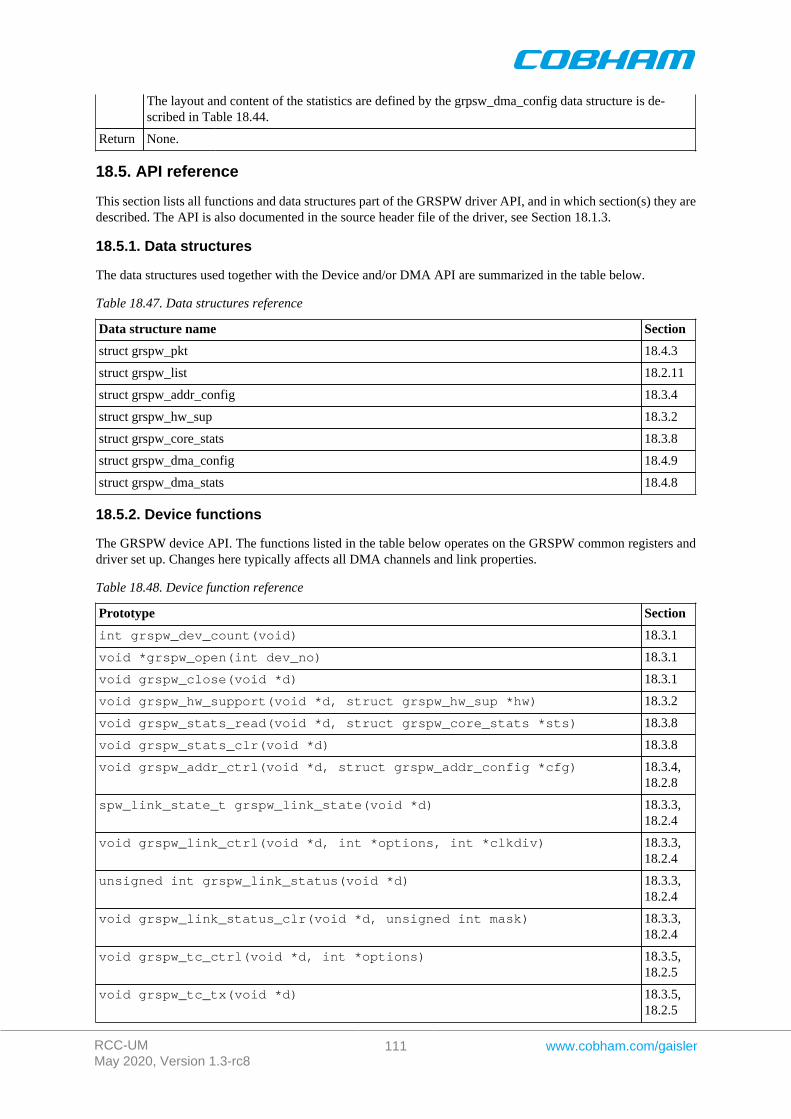
RCC-UMMay 2020, Version 1.3-rc8
111 www.cobham.com/gaisler
The layout and content of the statistics are defined by the grpsw_dma_config data structure is de-scribed in Table 18.44.
Return None.
18.5. API reference
This section lists all functions and data structures part of the GRSPW driver API, and in which section(s) they aredescribed. The API is also documented in the source header file of the driver, see Section 18.1.3.
18.5.1. Data structures
The data structures used together with the Device and/or DMA API are summarized in the table below.
Table 18.47. Data structures reference
Data structure name Section
struct grspw_pkt 18.4.3
struct grspw_list 18.2.11
struct grspw_addr_config 18.3.4
struct grspw_hw_sup 18.3.2
struct grspw_core_stats 18.3.8
struct grspw_dma_config 18.4.9
struct grspw_dma_stats 18.4.8
18.5.2. Device functions
The GRSPW device API. The functions listed in the table below operates on the GRSPW common registers anddriver set up. Changes here typically affects all DMA channels and link properties.
Table 18.48. Device function reference
Prototype Section
int grspw_dev_count(void) 18.3.1
void *grspw_open(int dev_no) 18.3.1
void grspw_close(void *d) 18.3.1
void grspw_hw_support(void *d, struct grspw_hw_sup *hw) 18.3.2
void grspw_stats_read(void *d, struct grspw_core_stats *sts) 18.3.8
void grspw_stats_clr(void *d) 18.3.8
void grspw_addr_ctrl(void *d, struct grspw_addr_config *cfg) 18.3.4,18.2.8
spw_link_state_t grspw_link_state(void *d) 18.3.3,18.2.4
void grspw_link_ctrl(void *d, int *options, int *clkdiv) 18.3.3,18.2.4
unsigned int grspw_link_status(void *d) 18.3.3,18.2.4
void grspw_link_status_clr(void *d, unsigned int mask) 18.3.3,18.2.4
void grspw_tc_ctrl(void *d, int *options) 18.3.5,18.2.5
void grspw_tc_tx(void *d) 18.3.5,18.2.5
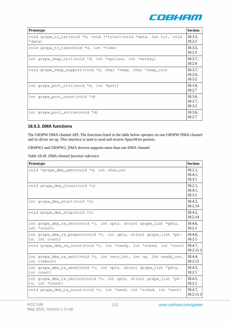
RCC-UMMay 2020, Version 1.3-rc8
112 www.cobham.com/gaisler
Prototype Section
void grspw_tc_isr(void *d, void (*tcisr)(void *data, int tc), void*data)
18.3.5,18.2.5
void grspw_tc_time(void *d, int *time) 18.3.5,18.2.5
int grspw_rmap_ctrl(void *d, int *options, int *dstkey) 18.3.7,18.2.6
void grspw_rmap_support(void *d, char *rmap, char *rmap_crc) 18.3.7,18.2.6,18.3.2
int grspw_port_ctrl(void *d, int *port) 18.3.6,18.2.7
int grspw_port_count(void *d) 18.3.6,18.2.7,18.3.2
int grspw_port_active(void *d) 18.3.6,18.2.7
18.5.3. DMA functions
The GRSPW DMA channel API. The functions listed in the table below operates on one GRSPW DMA channeland its driver set up. This interface is used to send and receive SpaceWire packets.
GRSPW2 and GRSPW2_DMA devices supports more than one DMA channel.
Table 18.49. DMA channel function reference
Prototype Section
void *grspw_dma_open(void *d, int chan_no) 18.2.1,18.4.1,18.3.1
void grspw_dma_close(void *c) 18.2.1,18.4.1,18.3.1
int grspw_dma_start(void *c) 18.4.2,18.2.14
void grspw_dma_stop(void *c) 18.4.2,18.2.14
int grspw_dma_rx_recv(void *c, int opts, struct grspw_list *pkts,int *count)
18.4.6,18.2.1
int grspw_dma_rx_prepare(void *c, int opts, struct grspw_list *pk-ts, int count)
18.4.6,18.2.1
void grspw_dma_rx_count(void *c, int *ready, int *sched, int *recv) 18.4.7,18.2.11.1
int grspw_dma_rx_wait(void *c, int recv_cnt, int op, int ready_cnt,int timeout)
18.4.4,18.2.12
int grspw_dma_tx_send(void *c, int opts, struct grspw_list *pkts,int count)
18.4.5,18.2.1
int grspw_dma_tx_reclaim(void *c, int opts, struct grspw_list *pk-ts, int *count)
18.4.5,18.2.1
void grspw_dma_tx_count(void *c, int *send, int *sched, int *sent) 18.4.7,18.2.11.1
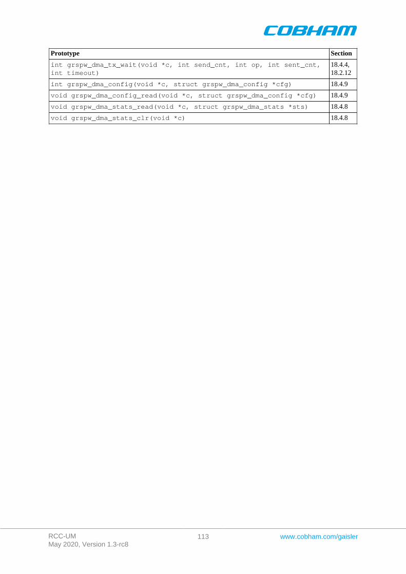
RCC-UMMay 2020, Version 1.3-rc8
113 www.cobham.com/gaisler
Prototype Section
int grspw_dma_tx_wait(void *c, int send_cnt, int op, int sent_cnt,int timeout)
18.4.4,18.2.12
int grspw_dma_config(void *c, struct grspw_dma_config *cfg) 18.4.9
void grspw_dma_config_read(void *c, struct grspw_dma_config *cfg) 18.4.9
void grspw_dma_stats_read(void *c, struct grspw_dma_stats *sts) 18.4.8
void grspw_dma_stats_clr(void *c) 18.4.8
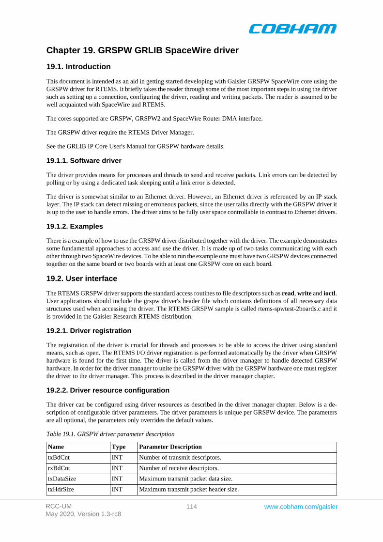
RCC-UMMay 2020, Version 1.3-rc8
114 www.cobham.com/gaisler
Chapter 19. GRSPW GRLIB SpaceWire driver
19.1. Introduction
This document is intended as an aid in getting started developing with Gaisler GRSPW SpaceWire core using theGRSPW driver for RTEMS. It briefly takes the reader through some of the most important steps in using the driversuch as setting up a connection, configuring the driver, reading and writing packets. The reader is assumed to bewell acquainted with SpaceWire and RTEMS.
The cores supported are GRSPW, GRSPW2 and SpaceWire Router DMA interface.
The GRSPW driver require the RTEMS Driver Manager.
See the GRLIB IP Core User's Manual for GRSPW hardware details.
19.1.1. Software driver
The driver provides means for processes and threads to send and receive packets. Link errors can be detected bypolling or by using a dedicated task sleeping until a link error is detected.
The driver is somewhat similar to an Ethernet driver. However, an Ethernet driver is referenced by an IP stacklayer. The IP stack can detect missing or erroneous packets, since the user talks directly with the GRSPW driver itis up to the user to handle errors. The driver aims to be fully user space controllable in contrast to Ethernet drivers.
19.1.2. Examples
There is a example of how to use the GRSPW driver distributed together with the driver. The example demonstratessome fundamental approaches to access and use the driver. It is made up of two tasks communicating with eachother through two SpaceWire devices. To be able to run the example one must have two GRSPW devices connectedtogether on the same board or two boards with at least one GRSPW core on each board.
19.2. User interface
The RTEMS GRSPW driver supports the standard access routines to file descriptors such as read, write and ioctl.User applications should include the grspw driver's header file which contains definitions of all necessary datastructures used when accessing the driver. The RTEMS GRSPW sample is called rtems-spwtest-2boards.c and itis provided in the Gaisler Research RTEMS distribution.
19.2.1. Driver registration
The registration of the driver is crucial for threads and processes to be able to access the driver using standardmeans, such as open. The RTEMS I/O driver registration is performed automatically by the driver when GRSPWhardware is found for the first time. The driver is called from the driver manager to handle detected GRSPWhardware. In order for the driver manager to unite the GRSPW driver with the GRSPW hardware one must registerthe driver to the driver manager. This process is described in the driver manager chapter.
19.2.2. Driver resource configuration
The driver can be configured using driver resources as described in the driver manager chapter. Below is a de-scription of configurable driver parameters. The driver parameters is unique per GRSPW device. The parametersare all optional, the parameters only overrides the default values.
Table 19.1. GRSPW driver parameter description
Name Type Parameter Description
txBdCnt INT Number of transmit descriptors.
rxBdCnt INT Number of receive descriptors.
txDataSize INT Maximum transmit packet data size.
txHdrSize INT Maximum transmit packet header size.
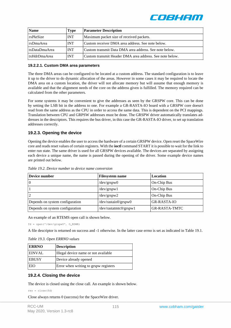
RCC-UMMay 2020, Version 1.3-rc8
115 www.cobham.com/gaisler
Name Type Parameter Description
rxPktSize INT Maximum packet size of received packets.
rxDmaArea INT Custom receiver DMA area address. See note below.
txDataDmaArea INT Custom transmit Data DMA area address. See note below.
txHdrDmaArea INT Custom transmit Header DMA area address. See note below.
19.2.2.1. Custom DMA area parameters
The three DMA areas can be configured to be located at a custom address. The standard configuration is to leaveit up to the driver to do dynamic allocation of the areas. However in some cases it may be required to locate theDMA area on a custom location, the driver will not allocate memory but will assume that enough memory isavailable and that the alignment needs of the core on the address given is fulfilled. The memory required can becalculated from the other parameters.
For some systems it may be convenient to give the addresses as seen by the GRSPW core. This can be doneby setting the LSB bit in the address to one. For example a GR-RASTA-IO board with a GRSPW core doesn'tread from the same address as the CPU in order to access the same data. This is dependent on the PCI mappings.Translation between CPU and GRPSW addresses must be done. The GRSPW driver automatically translates ad-dresses in the descriptors. This requires the bus driver, in this case the GR-RASTA-IO driver, to set up translationaddresses correctly.
19.2.3. Opening the device
Opening the device enables the user to access the hardware of a certain GRSPW device. Open reset the SpaceWirecore and reads reset values of certain registers. With the ioctl command START it is possible to wait for the link toenter run state. The same driver is used for all GRSPW devices available. The devices are separated by assigningeach device a unique name, the name is passed during the opening of the driver. Some example device namesare printed out below.
Table 19.2. Device number to device name conversion
Device number Filesystem name Location
0 /dev/grspw0 On-Chip Bus
1 /dev/grspw1 On-Chip Bus
2 /dev/grspw2 On-Chip Bus
Depends on system configuration /dev/rastaio0/grspw0 GR-RASTA-IO
Depends on system configuration /dev/rastatmtc0/grspw1 GR-RASTA-TMTC
An example of an RTEMS open call is shown below.
fd = open("/dev/grspw0", O_RDWR)
A file descriptor is returned on success and -1 otherwise. In the latter case errno is set as indicated in Table 19.1.
Table 19.3. Open ERRNO values
ERRNO Description
EINVAL Illegal device name or not available
EBUSY Device already opened
EIO Error when writing to grspw registers
19.2.4. Closing the device
The device is closed using the close call. An example is shown below.
res = close(fd)
Close always returns 0 (success) for the SpaceWire driver.
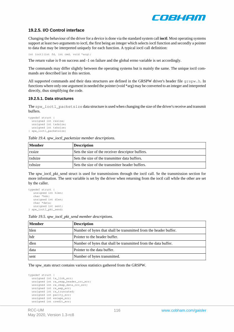
RCC-UMMay 2020, Version 1.3-rc8
116 www.cobham.com/gaisler
19.2.5. I/O Control interface
Changing the behaviour of the driver for a device is done via the standard system call ioctl. Most operating systemssupport at least two arguments to ioctl, the first being an integer which selects ioctl function and secondly a pointerto data that may be interpreted uniquely for each function. A typical ioctl call definition:
int ioctl(int fd, int cmd, void *arg);
The return value is 0 on success and -1 on failure and the global errno variable is set accordingly.
The commands may differ slightly between the operating systems but is mainly the same. The unique ioctl com-mands are described last in this section.
All supported commands and their data structures are defined in the GRSPW driver's header file grspw.h. Infunctions where only one argument in needed the pointer (void *arg) may be converted to an integer and interpreteddirectly, thus simplifying the code.
19.2.5.1. Data structures
The spw_ioctl_packetsize data structure is used when changing the size of the driver's receive and transmitbuffers.
typedef struct { unsigned int rxsize; unsigned int txdsize; unsigned int txhsize;} spw_ioctl_packetsize;
Table 19.4. spw_ioctl_packetsize member descriptions.
Member Description
rxsize Sets the size of the receiver descriptor buffers.
txdsize Sets the size of the transmitter data buffers.
txhsize Sets the size of the transmitter header buffers.
The spw_ioctl_pkt_send struct is used for transmissions through the ioctl call. Se the transmission section formore information. The sent variable is set by the driver when returning from the ioctl call while the other are setby the caller.
typedef struct { unsigned int hlen; char *hdr; unsigned int dlen; char *data; unsigned int sent;} spw_ioctl_pkt_send;
Table 19.5. spw_ioctl_pkt_send member descriptions.
Member Description
hlen Number of bytes that shall be transmitted from the header buffer.
hdr Pointer to the header buffer.
dlen Number of bytes that shall be transmitted from the data buffer.
data Pointer to the data buffer.
sent Number of bytes transmitted.
The spw_stats struct contains various statistics gathered from the GRSPW.
typedef struct { unsigned int tx_link_err; unsigned int rx_rmap_header_crc_err; unsigned int rx_rmap_data_crc_err; unsigned int rx_eep_err; unsigned int rx_truncated; unsigned int parity_err; unsigned int escape_err; unsigned int credit_err;
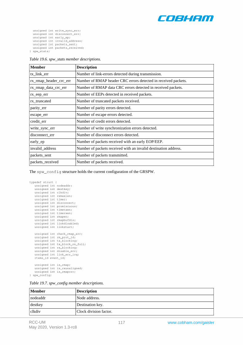
RCC-UMMay 2020, Version 1.3-rc8
117 www.cobham.com/gaisler
unsigned int write_sync_err; unsigned int disconnect_err; unsigned int early_ep; unsigned int invalid_address; unsigned int packets_sent; unsigned int packets_received;} spw_stats;
Table 19.6. spw_stats member descriptions.
Member Description
tx_link_err Number of link-errors detected during transmission.
rx_rmap_header_crc_err Number of RMAP header CRC errors detected in received packets.
rx_rmap_data_crc_err Number of RMAP data CRC errors detected in received packets.
rx_eep_err Number of EEPs detected in received packets.
rx_truncated Number of truncated packets received.
parity_err Number of parity errors detected.
escape_err Number of escape errors detected.
credit_err Number of credit errors detected.
write_sync_err Number of write synchronization errors detected.
disconnect_err Number of disconnect errors detected.
early_ep Number of packets received with an early EOP/EEP.
invalid_address Number of packets received with an invalid destination address.
packets_sent Number of packets transmitted.
packets_received Number of packets received.
The spw_config structure holds the current configuration of the GRSPW.
typedef struct { unsigned int nodeaddr; unsigned int destkey; unsigned int clkdiv; unsigned int rxmaxlen; unsigned int timer; unsigned int disconnect; unsigned int promiscuous; unsigned int timetxen; unsigned int timerxen; unsigned int rmapen; unsigned int rmapbufdis; unsigned int linkdisabled; unsigned int linkstart;
unsigned int check_rmap_err; unsigned int rm_prot_id; unsigned int tx_blocking; unsigned int tx_block_on_full; unsigned int rx_blocking; unsigned int disable_err; unsigned int link_err_irq; rtems_id event_id;
unsigned int is_rmap; unsigned int is_rxunaligned; unsigned int is_rmapcrc;} spw_config;
Table 19.7. spw_config member descriptions.
Member Description
nodeaddr Node address.
destkey Destination key.
clkdiv Clock division factor.
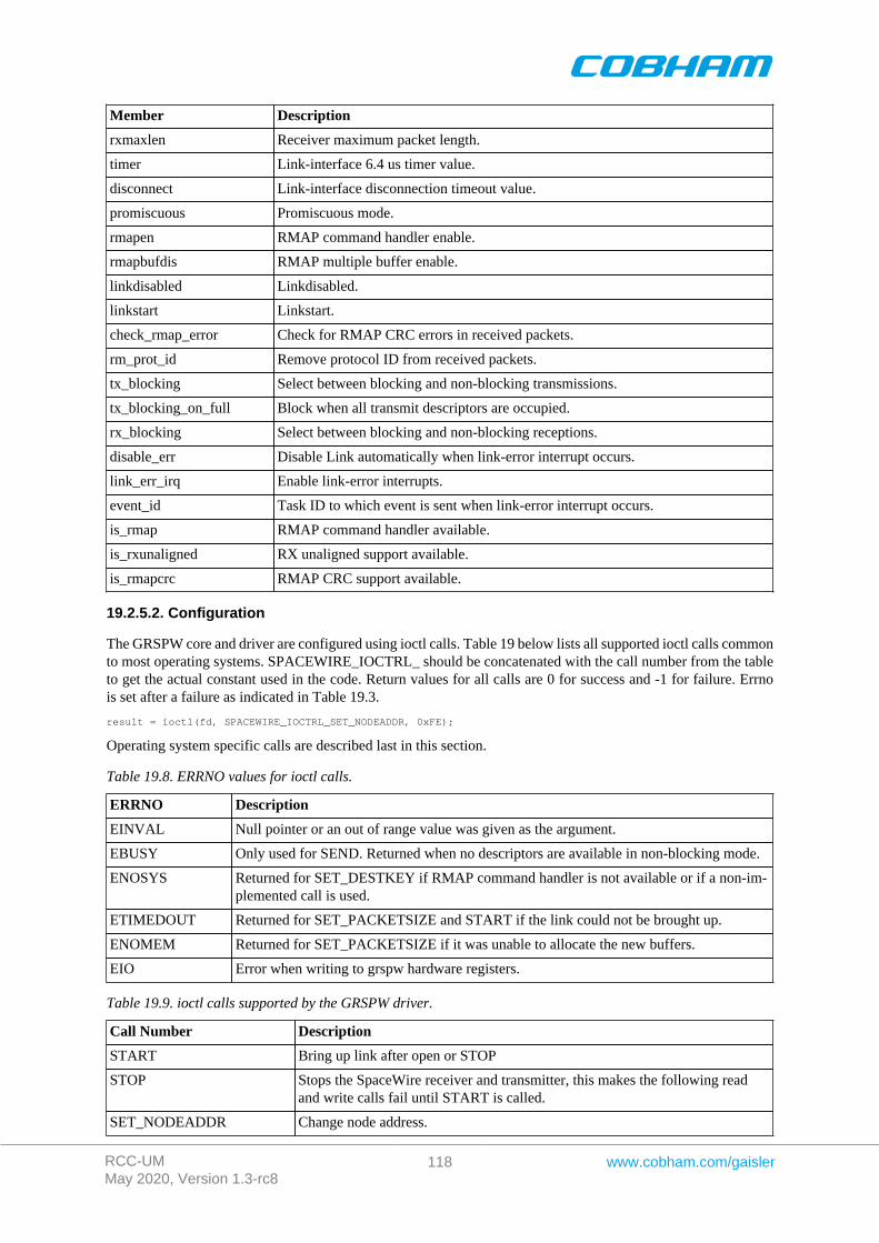
RCC-UMMay 2020, Version 1.3-rc8
118 www.cobham.com/gaisler
Member Description
rxmaxlen Receiver maximum packet length.
timer Link-interface 6.4 us timer value.
disconnect Link-interface disconnection timeout value.
promiscuous Promiscuous mode.
rmapen RMAP command handler enable.
rmapbufdis RMAP multiple buffer enable.
linkdisabled Linkdisabled.
linkstart Linkstart.
check_rmap_error Check for RMAP CRC errors in received packets.
rm_prot_id Remove protocol ID from received packets.
tx_blocking Select between blocking and non-blocking transmissions.
tx_blocking_on_full Block when all transmit descriptors are occupied.
rx_blocking Select between blocking and non-blocking receptions.
disable_err Disable Link automatically when link-error interrupt occurs.
link_err_irq Enable link-error interrupts.
event_id Task ID to which event is sent when link-error interrupt occurs.
is_rmap RMAP command handler available.
is_rxunaligned RX unaligned support available.
is_rmapcrc RMAP CRC support available.
19.2.5.2. Configuration
The GRSPW core and driver are configured using ioctl calls. Table 19 below lists all supported ioctl calls commonto most operating systems. SPACEWIRE_IOCTRL_ should be concatenated with the call number from the tableto get the actual constant used in the code. Return values for all calls are 0 for success and -1 for failure. Errnois set after a failure as indicated in Table 19.3.
result = ioctl(fd, SPACEWIRE_IOCTRL_SET_NODEADDR, 0xFE);
Operating system specific calls are described last in this section.
Table 19.8. ERRNO values for ioctl calls.
ERRNO Description
EINVAL Null pointer or an out of range value was given as the argument.
EBUSY Only used for SEND. Returned when no descriptors are available in non-blocking mode.
ENOSYS Returned for SET_DESTKEY if RMAP command handler is not available or if a non-im-plemented call is used.
ETIMEDOUT Returned for SET_PACKETSIZE and START if the link could not be brought up.
ENOMEM Returned for SET_PACKETSIZE if it was unable to allocate the new buffers.
EIO Error when writing to grspw hardware registers.
Table 19.9. ioctl calls supported by the GRSPW driver.
Call Number Description
START Bring up link after open or STOP
STOP Stops the SpaceWire receiver and transmitter, this makes the following readand write calls fail until START is called.
SET_NODEADDR Change node address.
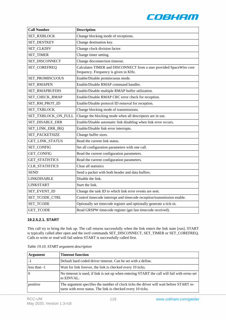
RCC-UMMay 2020, Version 1.3-rc8
119 www.cobham.com/gaisler
Call Number Description
SET_RXBLOCK Change blocking mode of receptions.
SET_DESTKEY Change destination key.
SET_CLKDIV Change clock division factor.
SET_TIMER Change timer setting.
SET_DISCONNECT Change disconnection timeout.
SET_COREFREQ Calculates TIMER and DISCONNECT from a user provided SpaceWire corefrequency. Frequency is given in KHz.
SET_PROMISCUOUS Enable/Disable promiscuous mode.
SET_RMAPEN Enable/Disable RMAP command handler.
SET_RMAPBUFDIS Enable/Disable multiple RMAP buffer utilization.
SET_CHECK_RMAP Enable/Disable RMAP CRC error check for reception.
SET_RM_PROT_ID Enable/Disable protocol ID removal for reception.
SET_TXBLOCK Change blocking mode of transmissions.
SET_TXBLOCK_ON_FULL Change the blocking mode when all descriptors are in use.
SET_DISABLE_ERR Enable/Disable automatic link disabling when link error occurs.
SET_LINK_ERR_IRQ Enable/Disable link error interrupts.
SET_PACKETSIZE Change buffer sizes.
GET_LINK_STATUS Read the current link status.
SET_CONFIG Set all configuration parameters with one call.
GET_CONFIG Read the current configuration parameters.
GET_STATISTICS Read the current configuration parameters.
CLR_STATISTICS Clear all statistics
SEND Send a packet with both header and data buffers.
LINKDISABLE Disable the link.
LINKSTART Start the link.
SET_EVENT_ID Change the task ID to which link error events are sent.
SET_TCODE_CTRL Control timecode interrupt and timecode reception/transmission enable.
SET_TCODE Optionally set timecode register and optionally generate a tick-in.
GET_TCODE Read GRSPW timecode register (get last timecode received).
19.2.5.2.1. START
This call try to bring the link up. The call returns successfully when the link enters the link state [run]. STARTis typically called after open and the ioctl commands SET_DISCONNECT, SET_TIMER or SET_COREFREQ.Calls to write or read will fail unless START is successfully called first.
Table 19.10. START argument description
Argument Timeout function
-1 Default hard coded driver timeout. Can be set with a define.
less than -1 Wait for link forever, the link is checked every 10 ticks.
0 No timeout is used, if link is not up when entering START the call will fail with errno setto EINVAL.
positive The argument specifies the number of clock ticks the driver will wait before START re-turns with error status. The link is checked every 10 ticks.

RCC-UMMay 2020, Version 1.3-rc8
120 www.cobham.com/gaisler
19.2.5.2.2. STOP
STOP disables the GRSPW receiver and transmitter it does not effect link state. After calling STOP subsequentcalls to read and write will fail until START has successfully returned. The call takes no arguments. STOP neverfail.
19.2.5.2.3. SET_NODEADDR
This call sets the node address of the device. It is only used to check the destination of incoming packets. It is alsopossible to receive packets from all addresses, see SET_PROMISCUOUS.
The argument must be an integer in the range 0 to 255. The call will fail if the argument contains an illegal valueor if the register can not be written.
19.2.5.2.4. SET_RXBLOCK
This call sets the blocking mode for receptions. Setting this flag makes calls to read blocking when there is noavailable packets. If the flag is not set read will return EBUSY when there are no incoming packets available.
The argument must be an integer in the range 0 to 1. 0 selects non blocking mode while 1 selects blocking mode.The call will fail if the argument contains an illegal value.
19.2.5.2.5. SET_DESTKEY
This call sets the destination key. It can only be used if the RMAP command handler is available. The argumentmust be an integer in the range 0 to 255. The call will fail if the argument contains an illegal value, if the RMAPcommand handler is not available or if the register cannot be written.
19.2.5.2.6. SET_CLKDIV
This call sets the clock division factor used in the run-state. The argument must be an integer in the range 0 to 255.The call will fail if the argument contains an illegal value or if the register cannot be written.
19.2.5.2.7. SET_TIMER
This call sets the counter used to generate the 6.4 and 12.8 us time-outs in the link-interface FSM. The argumentmust be an integer in the range 0 to 4095. The call will fail if the argument contains an illegal value or if theregister cannot be written. This value can be calculated by the driver, see SET_COREFREQ.
19.2.5.2.8. SET_DISCONNECT
This call sets the counter used to generate the 850 ns disconnect interval in the link-interface FSM. The argumentmust be an integer in the range 0 to 1023. The call will fail if the argument contains an illegal value or if theregister cannot be written. This value can be calculated by the driver, see SET_COREFREQ.
19.2.5.2.9. SET_COREFREQ
This call calculates timer and disconnect from the GRSPW core frequency. The call take one unsigned 32-bitargument, see table below. This call can be used instead of the calls SET_TIMER and SET_DISCONNECT.
Table 19.11. SET_COREFREQ argument description
Argument Value Function
0 The GRSPW core frequency is assumed to be equal to the system frequency. The systemfrequency is detected by reading the system tick timer or a hard coded frequency.
all other values The argument is taken as the GRSPW core frequency in KHz.
19.2.5.2.10. SET_PROMISCUOUS
This call sets the promiscuous mode bit. The argument must be an integer in the range 0 to 1. The call will fail ifthe argument contains an illegal value or if the register cannot be written.

RCC-UMMay 2020, Version 1.3-rc8
121 www.cobham.com/gaisler
19.2.5.2.11. SET_RMAPEN
This call sets the RMAP enable bit. It can only be used if the RMAP command handler is available. The argumentmust be an integer in the range 0 to 1. The call will fail if the argument contains an illegal value, if the RMAPcommand handler is not available or if the register cannot be written.
19.2.5.2.12. SET_RMAPBUFDIS
This call sets the RMAP buffer disable bit. It can only be used if the RMAP command handler is available. Theargument must be an integer in the range 0 to 1. The call will fail if the argument contains an illegal value, if theRMAP command handler is not available or if the register cannot be written.
19.2.5.2.13. SET_CHECK_RMAP
This call selects whether or not RMAP CRC should be checked for received packets. If enabled the header CRCerror and data CRC error bits are checked and if one or both are set the packet will be discarded. The argumentmust be an integer in the range 0 to 1. 0 disables and 1 enables the RMAP CRC check. The call will fail if theargument contains an illegal value.
19.2.5.2.14. SET_RM_PROT_ID
This call selects whether or not the protocol ID should be removed from received packets. It is assumed that allpackets contain a protocol ID so when enabled the second byte (the one after the node address) in the packet willbe removed. The argument must be an integer in the range 0 to 1. 0 disables and 1 enables the RMAP CRC check.The call will fail if the argument contains an illegal value.
19.2.5.2.15. SET_TXBLOCK
This call sets the blocking mode for transmissions. The calling process will be blocked after each write until thewhole packet has been copied into the GRSPW send FIFO buffer.
The argument must be an integer in the range 0 to 1. 0 selects non blocking mode while 1 selects blocking mode.The call will fail if the argument contains an illegal value.
19.2.5.2.16. SET_TXBLOCK_ON_FULL
This call sets the blocking mode for transmissions when all transmit descriptors are in use. The argument mustbe an integer in the range 0 to 1. 0 selects non blocking mode while 1 selects blocking mode. The call will failif the argument contains an illegal value.
19.2.5.2.17. SET_DISABLE_ERR
This call sets automatic link-disabling due to link-error interrupts. Link-error interrupts must be enabled for it tohave any effect. The argument must be an integer in the range 0 to 1. 0 disables automatic link- disabling whilea 1 enables it. The call will fail if the argument contains an illegal value.
19.2.5.2.18. SET_LINK_ERR_IRQ
This call sets the link-error interrupt bit in the control register. The interrupt-handler sends an event to the taskspecified with the event_id field when this interrupt occurs. The argument must be an integer in the range 0 to 1.The call will fail if the argument contains an illegal value or if the register write fails.
19.2.5.2.19. SET_PACKETSIZE
This call changes the size of buffers and consequently the maximum packet sizes. The this cannot be done whilethe core accesses the buffers so first the receiver and the transmitter is disabled and ongoing DMA transactionsis waited upon to finish. The time taken to wait for receiving DMA transactions to finish may vary dependingon packet size and SpaceWire core frequency. The old buffers are reallocated and the receiver and transmitteris enabled again. The configuration before the call will be preserved (except for the packet sizes). The argumentmust be a pointer to a spw_ioctl_packetsize struct. The call will fail if the argument contains an illegalpointer, the requested buffer sizes cannot be allocated or the link cannot be re-started.

RCC-UMMay 2020, Version 1.3-rc8
122 www.cobham.com/gaisler
19.2.5.2.20. GET_LINK_STATUS
This call returns the current link status. The argument must be a pointer to an integer. The return value in theargument can be one of the following: 0 = Error-reset, 1 = Error-wait, 2 = Ready, 3 = Started, 4 = Connecting, 5= Run. The call will fail if the argument contains an illegal pointer.
19.2.5.2.21. GET_CONFIG
This call returns all configuration parameters in a spw_config struct which is defined in spacewire.h. Theargument must be a pointer to a spw_config struct. The call will fail if the argument contains an illegal pointer.
19.2.5.2.22. GET_STATISTICS
This call returns all statistics in a spw_stats struct. The argument must be a pointer to a spw_stats struct.The call will fail if the argument contains an illegal pointer.
19.2.5.2.23. CLR_STATISTICS
This call clears all statistics. No argument is taken and the call always succeeds.
19.2.5.2.24. SEND
This call sends a packet. The difference to the normal write call is that separate data and header buffers can beused. The argument must be a pointer to a spw_ioctl_send struct. The call will fail if the argument contains anillegal pointer, or the struct contains illegal values. See the transmission section for more information.
19.2.5.2.25. LINKDISABLE
This call disables the link (sets the linkdisable bit to 1 and the linkstart bit to 0). No argument is taken. The callfails if the register write fails.
19.2.5.2.26. LINKSTART
This call starts the link (sets the linkdisable bit to 0 and the linkstart bit to 1). No argument is taken. The call failsif the register write fails.
19.2.5.2.27. SET_EVENT_ID
This call sets the task ID to which an event is sent when a link-error interrupt occurs. The argument can be anypositive integer. The call will fail if the argument contains an illegal value.
19.2.5.2.28. SET_TCODE_CTRL
This call is used to control the timecode functionality of the GRSPW core. The TR (Timecode RX Enable), TT(Timecode TX enable) and TQ (Tick-out IRQ) bits in the control register can be set or cleared, if tick-out IRQis enabled global IRQ is also enabled. The argument is a 12-bit mask, the least significant four bits determineswhich bits are written (mask), the upper four bits determine the new register value of the enabled bits, please seethe SPACEWIRE_TCODE_CTRL_* definitions.
When Tick-out interrupt is enabled the grspw_timecode_callback function is called for every tick-out thatis received, it is called from the interrupt service routine in interrupt context. The function pointer must be setby the user to point to a function to handle tick-in interrupts. The function is global for all GRSPW devices, thearguments [regs] and [minor] both identify an unique GRSPW core and the [tc] argument determines the currentvalue of the timecode register upon interrupt.
void (*grspw_timecode_callback) (void *pDev, void *regs, int minor, unsigned int tc);
19.2.5.2.29. SET_TCODE
This call sets the timecode register and/or generates a tick-in. The operation is controlled by the argument bit-mask, setting SPACEWIRE_TCODE_SET will result in the lower 8-bits will be written to the timecode register
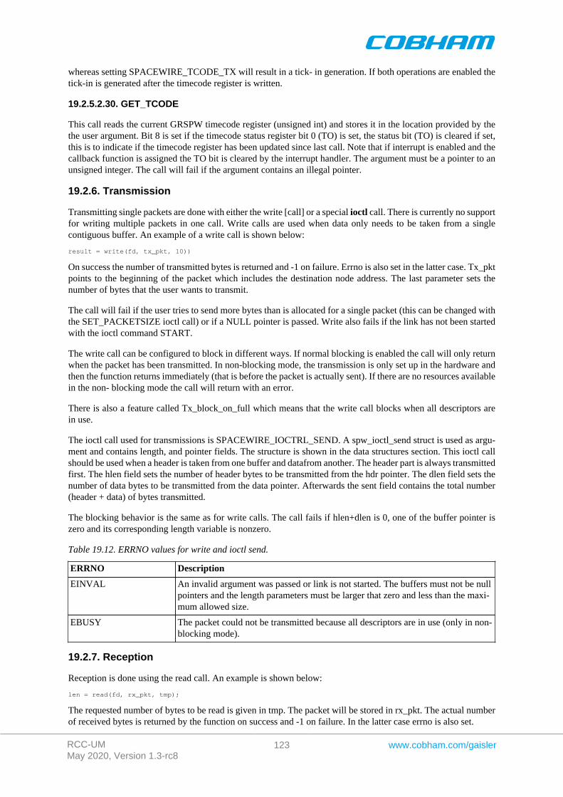
RCC-UMMay 2020, Version 1.3-rc8
123 www.cobham.com/gaisler
whereas setting SPACEWIRE_TCODE_TX will result in a tick- in generation. If both operations are enabled thetick-in is generated after the timecode register is written.
19.2.5.2.30. GET_TCODE
This call reads the current GRSPW timecode register (unsigned int) and stores it in the location provided by thethe user argument. Bit 8 is set if the timecode status register bit 0 (TO) is set, the status bit (TO) is cleared if set,this is to indicate if the timecode register has been updated since last call. Note that if interrupt is enabled and thecallback function is assigned the TO bit is cleared by the interrupt handler. The argument must be a pointer to anunsigned integer. The call will fail if the argument contains an illegal pointer.
19.2.6. Transmission
Transmitting single packets are done with either the write [call] or a special ioctl call. There is currently no supportfor writing multiple packets in one call. Write calls are used when data only needs to be taken from a singlecontiguous buffer. An example of a write call is shown below:
result = write(fd, tx_pkt, 10))
On success the number of transmitted bytes is returned and -1 on failure. Errno is also set in the latter case. Tx_pktpoints to the beginning of the packet which includes the destination node address. The last parameter sets thenumber of bytes that the user wants to transmit.
The call will fail if the user tries to send more bytes than is allocated for a single packet (this can be changed withthe SET_PACKETSIZE ioctl call) or if a NULL pointer is passed. Write also fails if the link has not been startedwith the ioctl command START.
The write call can be configured to block in different ways. If normal blocking is enabled the call will only returnwhen the packet has been transmitted. In non-blocking mode, the transmission is only set up in the hardware andthen the function returns immediately (that is before the packet is actually sent). If there are no resources availablein the non- blocking mode the call will return with an error.
There is also a feature called Tx_block_on_full which means that the write call blocks when all descriptors arein use.
The ioctl call used for transmissions is SPACEWIRE_IOCTRL_SEND. A spw_ioctl_send struct is used as argu-ment and contains length, and pointer fields. The structure is shown in the data structures section. This ioctl callshould be used when a header is taken from one buffer and datafrom another. The header part is always transmittedfirst. The hlen field sets the number of header bytes to be transmitted from the hdr pointer. The dlen field sets thenumber of data bytes to be transmitted from the data pointer. Afterwards the sent field contains the total number(header + data) of bytes transmitted.
The blocking behavior is the same as for write calls. The call fails if hlen+dlen is 0, one of the buffer pointer iszero and its corresponding length variable is nonzero.
Table 19.12. ERRNO values for write and ioctl send.
ERRNO Description
EINVAL An invalid argument was passed or link is not started. The buffers must not be nullpointers and the length parameters must be larger that zero and less than the maxi-mum allowed size.
EBUSY The packet could not be transmitted because all descriptors are in use (only in non-blocking mode).
19.2.7. Reception
Reception is done using the read call. An example is shown below:
len = read(fd, rx_pkt, tmp);
The requested number of bytes to be read is given in tmp. The packet will be stored in rx_pkt. The actual numberof received bytes is returned by the function on success and -1 on failure. In the latter case errno is also set.
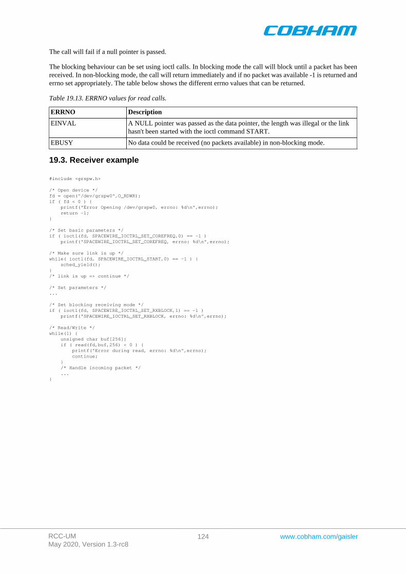
RCC-UMMay 2020, Version 1.3-rc8
124 www.cobham.com/gaisler
The call will fail if a null pointer is passed.
The blocking behaviour can be set using ioctl calls. In blocking mode the call will block until a packet has beenreceived. In non-blocking mode, the call will return immediately and if no packet was available -1 is returned anderrno set appropriately. The table below shows the different errno values that can be returned.
Table 19.13. ERRNO values for read calls.
ERRNO Description
EINVAL A NULL pointer was passed as the data pointer, the length was illegal or the linkhasn't been started with the ioctl command START.
EBUSY No data could be received (no packets available) in non-blocking mode.
19.3. Receiver example
#include <grspw.h>
/* Open device */fd = open("/dev/grspw0",O_RDWR);if ( fd < 0 ) { printf("Error Opening /dev/grspw0, errno: %d\n",errno); return -1;}
/* Set basic parameters */if ( ioctl(fd, SPACEWIRE_IOCTRL_SET_COREFREQ,0) == -1 ) printf("SPACEWIRE_IOCTRL_SET_COREFREQ, errno: %d\n",errno);
/* Make sure link is up */while( ioctl(fd, SPACEWIRE_IOCTRL_START,0) == -1 ) { sched_yield();}/* link is up => continue */
/* Set parameters */...
/* Set blocking receiving mode */if ( ioctl(fd, SPACEWIRE_IOCTRL_SET_RXBLOCK,1) == -1 ) printf("SPACEWIRE_IOCTRL_SET_RXBLOCK, errno: %d\n",errno);
/* Read/Write */while(1) { unsigned char buf[256]; if ( read(fd,buf,256) < 0 ) { printf("Error during read, errno: %d\n",errno); continue; } /* Handle incoming packet */ ...}
RCC-UMMay 2020, Version 1.3-rc8
125 www.cobham.com/gaisler
Chapter 20. GRSPW ROUTER driver
20.1. Introduction
This section describes the GRSPW ROUTER driver for SPARC/LEON processors in RTEMS. The router doesnot have to be located on the same bus as the processor running RTEMS. The RTEMS driver manager abstractsthe actual location of the device allowing application software to access the router resources always using thesame API. Two different drivers, the GRSPW router driver and GRSPW driver, are needed to utilize the completefunctionality of the router.
• GRSPW router driver: The main functionality of the router is to transfer packets between the SpaceWireports. This ability is functional after reset without any configuration. The router driver can be used to changethe configuration, enable/disable links, collect statistics, fault detection etc.
• GRSPW driver: There are three different port types in the router: SpW ports, FIFO ports and AMBA ports.The data path of SpW and FIFO ports are not (directly) accessible from the processor. If the router has AMBAports they can be used for transferring packets. The AMBA ports have identical interfaces to the GRSPWcore so they use the same driver. To transfer packets through an AMBA port a file handle should be opened toit and then read and write calls can be used to receive and send packets. The driver also allows configurationand status options in the AMBA port to be accessed.
20.1.1. Hardware Support
The GRSPW ROUTER core hardware interface is documented in the GRIP Core User's manual. Below is a listof the major hardware features it supports:
• Multiple Spacewire ports.• Multiple AMBA ports.• Multiple FIFO ports.• RMAP support.• Group adaptive routing.• Packet distribution.• System time distribution.• Distributed interrupts.
20.1.2. Driver sources
The driver sources and definitions are listed in the table below, the path is given relative to the RTEMS sourcetree rtems-5/c/src/lib/libbsp/sparc.
Table 20.1. GRSPW ROUTER driver source location
Location Description
shared/include/grspw_router.h GRSPW ROUTER user interface definition
.../libbsp/sparc/shared/spw/grspw_router.c
GRSPW ROUTER driver implementation
20.1.3. Examples
There is an example available that uses the GRSPW ROUTER driver to configure the router in a SPW performancetest. The example is part of the RCC distribution, it can be found under /opt/rtems-5/src/samples/spw/router_demo/test.c.
20.2. Software design overview
The driver has been implemented using the Driver Manager Framework. The driver provides a kernel functioninterface, an API, rather than implementing a IO system device. The API is designed for multi-threadding, i.e.multiple threads operating on the driver independently. The driver supports multiple routers in the system. Thedriver contains lock or protection for SMP environments, see Section 20.2.3 for more information.
RCC-UMMay 2020, Version 1.3-rc8
126 www.cobham.com/gaisler
20.2.1. Driver usage
The driver provides a set of functions that allow to configure the GRSPW ROUTER. The following list summarizesthe available actions.
• Setting up the GRSPW ROUTER core (see Section 20.3.3).• Setting up the routing table (see Section 20.3.5).• Managing a port (see Section 20.3.7).• Managing time codes (see Section 20.3.10).• Managing interrupt code generation (see Section 20.3.11).
The normal use case for the GRSPW ROUTER is the following: First we should open the router we want to use(see Section 20.3.2). Then we configure the GRSPW ROUTER with the wanted configuration (see Section 20.3.3)and set up the routing table (see Section 20.3.5). Once the GRSPW ROUTER is configured, we can configure theports we are interested on (see Section 20.3.7). We can start or stop the link, and check the link status on eachport (see Section 20.3.8).
The driver provides support for port counters (see Section 20.3.9) It also offers support for timecodes (see Sec-tion 20.3.10) and interrupt generation (see Section 20.3.11).
When dealing with errors, the driver allows to generate SpW interrupt codes for different types of interrupts andports (see Section 20.3.11). The driver also allows the user to poll the port status to check if an error (or multiple)have occurred (see Section 20.3.12).
The different errors that the GRSPW ROUTER can report are:
• SpaceWire Plug-and-Play error.• Spill-if-not-ready.• Run-state entry.• Time code/distributed interrupt code tick truncation.• Packet length truncation.• Timeout spill.• Auxiliary configuration port error.• RMAP error.• Invalid address.• Link error.• Memory error.
20.2.2. Initialization
During early initialization when the operating system boots the GRSPW ROUTER driver, the driver does notmodify the hardware state of the GRSPW ROUTER apart from masking and clearing interrupts.
20.2.3. SMP Support and thread safe
The driver has been designed to be SMP and thread safe. This means that multiple tasks can configure the routerand ports at the same time. Driver data structures and interrupt handling routines are protected by a semaphore.Each port and its data structure have its own lock.
20.3. GRSPW ROUTER user interface
20.3.1. Return values
ROUTER_ERR_OK ROUTER_ERR_EINVAL ROUTER_ERR_ERROR ROUTER_ERR_TOOMANY ROUTER_ERR_IMPLEMENTED
All the driver function calls return the following values when an error occurred:
• ROUTER_ERR_OK - Successful execution.• ROUTER_ERR_EINVAL - Invalid input parameter. One of the input values checks failed.
RCC-UMMay 2020, Version 1.3-rc8
127 www.cobham.com/gaisler
• ROUTER_ERR_ERROR - Internal error. Can have different causes.• ROUTER_ERR_TOOMANY - Index exceeded the valid value, such an invalid port index.• ROUTER_ERR_IMPLEMENTED - Feature not supported or implemented.
Some functions also return a positive value upon successful execution, such as the time counter.
20.3.2. Opening/closing a router
void * router_open( int dev_no ) int router_close( void * router ) int router_hwinfo_get( void * router, struct router_hw_info * hwinfo )
The driver provides the open and close functions to manage the registered GRSPW routers. All driver functionsoperating on the router require the router pointer returned by the open function.
The hwinfo function returns the hardware information of the GRSPW router.
The open function returns a NULL pointer if something went wrong, otherwise it returns the router pointer. Theother functions return a negative value if something went wrong, as explained in Section 20.3.1. Otherwise, thefunction returns ROUTER_ERR_OK when successful.
Table 20.2. router_open function declaration
Proto void * router_open( int dev_no )
About Opens a router with the given dev_no index. It returns a pointer to the router when successfull. SeeSection 20.3.2.
dev_no [IN] IntegerParam
Registration index of the router.
Return void *. Router pointer when successful. Otherwise, returns a NULL pointer.
Table 20.3. router_close function declaration
Proto int router_close( void * router )
About Closes a router. See Section 20.3.2.
router [IN] PointerParam
Pointer to the router.
Return int. ROUTER_ERR_OK when successful. Otherwise, returns a negative value if something wentwrong, as explained in Section 20.3.1.
struct router_hw_info { uint8_t nports_spw; uint8_t nports_amba; uint8_t nports_fifo; int8_t timers_avail; int8_t pnp_avail; uint8_t ver_major; uint8_t ver_minor; uint8_t ver_patch; uint8_t iid;};
Table 20.4. router_hw_info data structure declaration
nports_spw Number of spw ports.
nports_amba Number of amba ports.
nports_fifo Number of fifo ports.
timers_avail Indicates if the router has support for timers, as described in the manual.
pnp_avail Indicates if the router has support for SpW Plug and Play, as described in the manual.
ver_major Major version of the router.
RCC-UMMay 2020, Version 1.3-rc8
128 www.cobham.com/gaisler
ver_minor Minor version of the router.
ver_patch Patch number of the router.
iid Instance ID of the router.
Table 20.5. router_hwinfo_get function declaration
Proto int router_hwinfo_get( void * router, struct router_hw_info * hwin-fo)
About Get the hardware info of a given router. See Section 20.3.2.
router [IN] PointerParam
Pointer to the router.
hwinfo [IN] PointerParam
Pointer to the harware info structure.
Return int. ROUTER_ERR_OK when successful. Otherwise, returns a negative value if something wentwrong, as explained in Section 20.3.1.
20.3.3. Configuring the router
int router_config_set( void * router, struct router_config * cfg ) int router_config_get( void * router, struct router_config * cfg ) int router_reset( void * router )
The driver provides the config set and get functions to configure the different GRSPW router registers, including:
• Configuration register.• Instance ID.• Initial divisor.• Timer prescaler.• Timer reload.
The router_config structure is used to pass the configuration. The structure has a flags member that indicates whichparts of the configuration are going to be set or get.
The driver also provides a reset function that resets the whole GRSPW router. Please note, that reseting the GRSPWrouter, also resets the GRSPW2 cores, including the DMA interfaces.
The driver provides an equivalent API that allow to configure each register individually as explained in Sec-tion 20.3.4.
These functions return a negative value if something went wrong, as explained in Section 20.3.1. Otherwise, thefunction returns ROUTER_ERR_OK when successful.
struct router_config { uint32_t flags; uint32_t config; uint8_t iid; uint8_t idiv; uint32_t timer_prescaler;};
Table 20.6. router_config data structure declaration
Flags that determine what configuration should be updated. All flags must be prefixed withROUTER_FLG_
Flag Description
CFG Set/Get router configuration register.
IID Set/Get router instance ID register.
flags
IDIV Set/Get router initial divisor register.
RCC-UMMay 2020, Version 1.3-rc8
129 www.cobham.com/gaisler
TPRES Set/Get router timer prescaler register.
TRLD Set/Get router timer reload register.
ALL All of the above.
config Router Configuration Register.
iid Set Instance ID.
idiv SpaceWire Link Initialization Clock Divisor.
timer_prescaler Timer prescaler.
Table 20.7. router_config_set function declaration
Proto int router_config_set( void * router, struct router_config * cfg)
About Set the configuration of a given router. See Section 20.3.3.
router [IN] PointerParam
Pointer to the router.
cfg [IN] PointerParam
Pointer to the router configuration structure.
Return int. ROUTER_ERR_OK when successful. Otherwise, returns a negative value if something wentwrong, as explained in Section 20.3.1.
Table 20.8. router_config_get function declaration
Proto int router_config_get( void * router, struct router_config * cfg)
About Get the configuration of a given router. See Section 20.3.3.
router [IN] PointerParam
Pointer to the router.
cfg [IN] PointerParam
Pointer to the router configuration structure.
Return int. ROUTER_ERR_OK when successful. Otherwise, returns a negative value if something wentwrong, as explained in Section 20.3.1.
Table 20.9. router_reset function declaration
Proto int router_reset( void * router )
About Reset a given router. See Section 20.3.3.
router [IN] PointerParam
Pointer to the router.
Return int. ROUTER_ERR_OK when successful. Otherwise, returns a negative value if something wentwrong, as explained in Section 20.3.1.
20.3.4. Configuring the router registers
int router_write_enable(void * router) int router_write_disable(void * router) int router_cfgsts_set(void * router, uint32_t cfgsts) int router_cfgsts_get(void * router, uint32_t * cfgsts) int router_instance_set(void * router, uint8_t iid) int router_instance_get(void * router, uint8_t * iid) int router_idiv_set(void * router, uint8_t idiv) int router_idiv_get(void * router, uint8_t * idiv) int router_tpresc_set(void * router, uint32_t prescaler) int router_tpresc_get(void * router, uint32_t * prescaler)
The driver provides this collection of get and set functions to configure the different GRSPW router registersindividually, including:
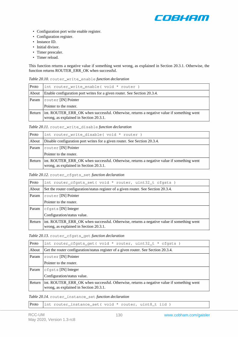
RCC-UMMay 2020, Version 1.3-rc8
130 www.cobham.com/gaisler
• Configuration port write enable register.• Configuration register.• Instance ID.• Initial divisor.• Timer prescaler.• Timer reload.
This function returns a negative value if something went wrong, as explained in Section 20.3.1. Otherwise, thefunction returns ROUTER_ERR_OK when successful.
Table 20.10. router_write_enable function declaration
Proto int router_write_enable( void * router )
About Enable configuration port writes for a given router. See Section 20.3.4.
router [IN] PointerParam
Pointer to the router.
Return int. ROUTER_ERR_OK when successful. Otherwise, returns a negative value if something wentwrong, as explained in Section 20.3.1.
Table 20.11. router_write_disable function declaration
Proto int router_write_disable( void * router )
About Disable configuration port writes for a given router. See Section 20.3.4.
router [IN] PointerParam
Pointer to the router.
Return int. ROUTER_ERR_OK when successful. Otherwise, returns a negative value if something wentwrong, as explained in Section 20.3.1.
Table 20.12. router_cfgsts_set function declaration
Proto int router_cfgsts_set( void * router, uint32_t cfgsts )
About Set the router configuration/status register of a given router. See Section 20.3.4.
router [IN] PointerParam
Pointer to the router.
cfgsts [IN] IntegerParam
Configuration/status value.
Return int. ROUTER_ERR_OK when successful. Otherwise, returns a negative value if something wentwrong, as explained in Section 20.3.1.
Table 20.13. router_cfgsts_get function declaration
Proto int router_cfgsts_get( void * router, uint32_t * cfgsts )
About Get the router configuration/status register of a given router. See Section 20.3.4.
router [IN] PointerParam
Pointer to the router.
cfgsts [IN] IntegerParam
Configuration/status value.
Return int. ROUTER_ERR_OK when successful. Otherwise, returns a negative value if something wentwrong, as explained in Section 20.3.1.
Table 20.14. router_instance_set function declaration
Proto int router_instance_set( void * router, uint8_t iid )
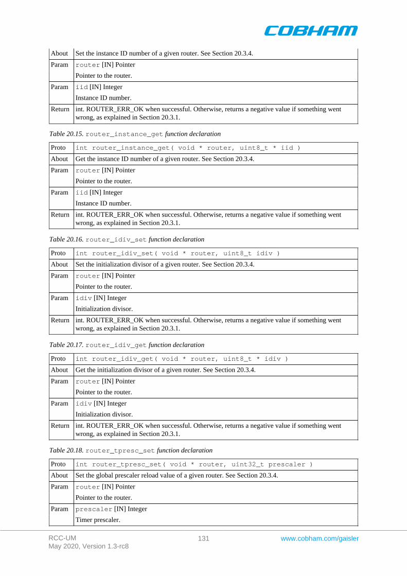
RCC-UMMay 2020, Version 1.3-rc8
131 www.cobham.com/gaisler
About Set the instance ID number of a given router. See Section 20.3.4.
router [IN] PointerParam
Pointer to the router.
iid [IN] IntegerParam
Instance ID number.
Return int. ROUTER_ERR_OK when successful. Otherwise, returns a negative value if something wentwrong, as explained in Section 20.3.1.
Table 20.15. router_instance_get function declaration
Proto int router_instance_get( void * router, uint8_t * iid )
About Get the instance ID number of a given router. See Section 20.3.4.
router [IN] PointerParam
Pointer to the router.
iid [IN] IntegerParam
Instance ID number.
Return int. ROUTER_ERR_OK when successful. Otherwise, returns a negative value if something wentwrong, as explained in Section 20.3.1.
Table 20.16. router_idiv_set function declaration
Proto int router_idiv_set( void * router, uint8_t idiv )
About Set the initialization divisor of a given router. See Section 20.3.4.
router [IN] PointerParam
Pointer to the router.
idiv [IN] IntegerParam
Initialization divisor.
Return int. ROUTER_ERR_OK when successful. Otherwise, returns a negative value if something wentwrong, as explained in Section 20.3.1.
Table 20.17. router_idiv_get function declaration
Proto int router_idiv_get( void * router, uint8_t * idiv )
About Get the initialization divisor of a given router. See Section 20.3.4.
router [IN] PointerParam
Pointer to the router.
idiv [IN] IntegerParam
Initialization divisor.
Return int. ROUTER_ERR_OK when successful. Otherwise, returns a negative value if something wentwrong, as explained in Section 20.3.1.
Table 20.18. router_tpresc_set function declaration
Proto int router_tpresc_set( void * router, uint32_t prescaler )
About Set the global prescaler reload value of a given router. See Section 20.3.4.
router [IN] PointerParam
Pointer to the router.
prescaler [IN] IntegerParam
Timer prescaler.
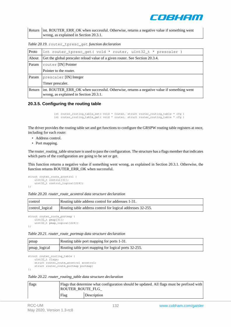
RCC-UMMay 2020, Version 1.3-rc8
132 www.cobham.com/gaisler
Return int. ROUTER_ERR_OK when successful. Otherwise, returns a negative value if something wentwrong, as explained in Section 20.3.1.
Table 20.19. router_tpresc_get function declaration
Proto int router_tpresc_get( void * router, uint32_t * prescaler )
About Get the global prescaler reload value of a given router. See Section 20.3.4.
router [IN] PointerParam
Pointer to the router.
prescaler [IN] IntegerParam
Timer prescaler.
Return int. ROUTER_ERR_OK when successful. Otherwise, returns a negative value if something wentwrong, as explained in Section 20.3.1.
20.3.5. Configuring the routing table
int router_routing_table_set( void * router, struct router_routing_table * cfg ) int router_routing_table_get( void * router, struct router_routing_table * cfg )
The driver provides the routing table set and get functions to configure the GRSPW routing table registers at once,including for each route:
• Address control.• Port mapping.
The router_routing_table structure is used to pass the configuration. The structure has a flags member that indicateswhich parts of the configuration are going to be set or get.
This function returns a negative value if something went wrong, as explained in Section 20.3.1. Otherwise, thefunction returns ROUTER_ERR_OK when successful.
struct router_route_acontrol { uint32_t control[31]; uint32_t control_logical[224]; };
Table 20.20. router_route_acontrol data structure declaration
control Routing table address control for addresses 1-31.
control_logical Routing table address control for logical addresses 32-255.
struct router_route_portmap { uint32_t pmap[31]; uint32_t pmap_logical[224];};
Table 20.21. router_route_portmap data structure declaration
pmap Routing table port mapping for ports 1-31.
pmap_logical Routing table port mapping for logical ports 32-255.
struct router_routing_table { uint32_t flags; struct router_route_acontrol acontrol; struct router_route_portmap portmap;};
Table 20.22. router_routing_table data structure declaration
Flags that determine what configuration should be updated. All flags must be prefixed withROUTER_ROUTE_FLG_
flags
Flag Description
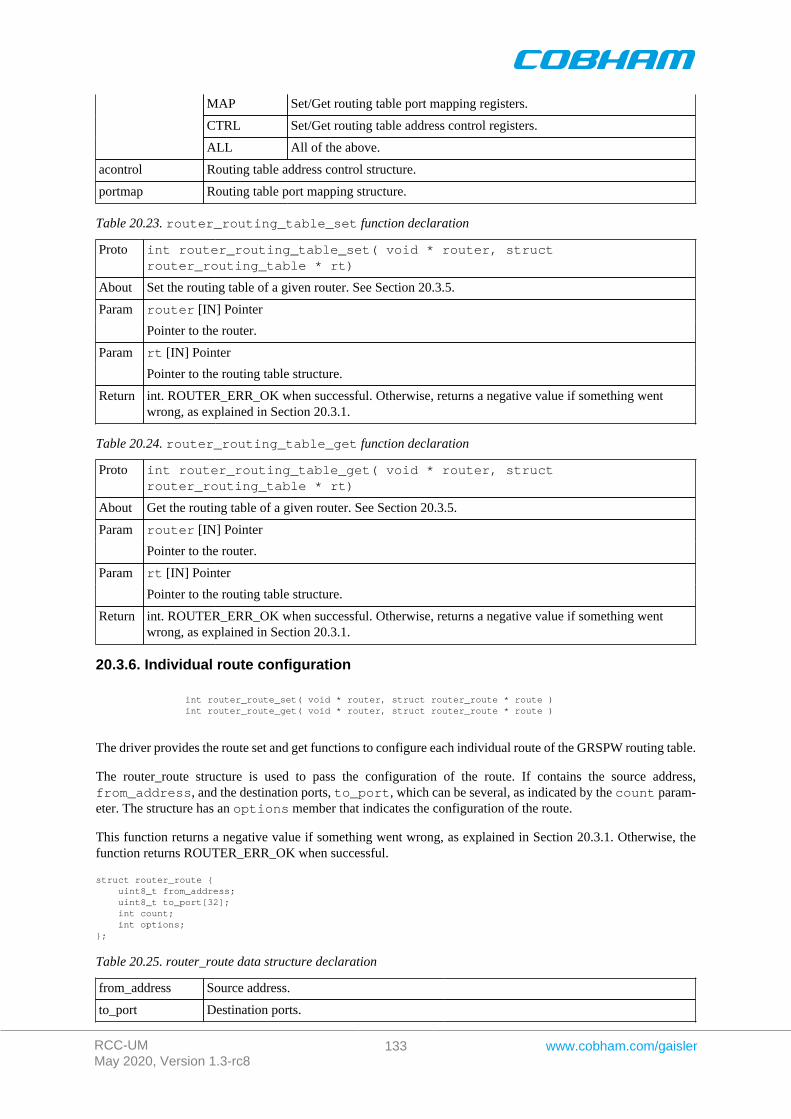
RCC-UMMay 2020, Version 1.3-rc8
133 www.cobham.com/gaisler
MAP Set/Get routing table port mapping registers.
CTRL Set/Get routing table address control registers.
ALL All of the above.
acontrol Routing table address control structure.
portmap Routing table port mapping structure.
Table 20.23. router_routing_table_set function declaration
Proto int router_routing_table_set( void * router, structrouter_routing_table * rt)
About Set the routing table of a given router. See Section 20.3.5.
router [IN] PointerParam
Pointer to the router.
rt [IN] PointerParam
Pointer to the routing table structure.
Return int. ROUTER_ERR_OK when successful. Otherwise, returns a negative value if something wentwrong, as explained in Section 20.3.1.
Table 20.24. router_routing_table_get function declaration
Proto int router_routing_table_get( void * router, structrouter_routing_table * rt)
About Get the routing table of a given router. See Section 20.3.5.
router [IN] PointerParam
Pointer to the router.
rt [IN] PointerParam
Pointer to the routing table structure.
Return int. ROUTER_ERR_OK when successful. Otherwise, returns a negative value if something wentwrong, as explained in Section 20.3.1.
20.3.6. Individual route configuration
int router_route_set( void * router, struct router_route * route ) int router_route_get( void * router, struct router_route * route )
The driver provides the route set and get functions to configure each individual route of the GRSPW routing table.
The router_route structure is used to pass the configuration of the route. If contains the source address,from_address, and the destination ports, to_port, which can be several, as indicated by the count param-eter. The structure has an options member that indicates the configuration of the route.
This function returns a negative value if something went wrong, as explained in Section 20.3.1. Otherwise, thefunction returns ROUTER_ERR_OK when successful.
struct router_route { uint8_t from_address; uint8_t to_port[32]; int count; int options;};
Table 20.25. router_route data structure declaration
from_address Source address.
to_port Destination ports.
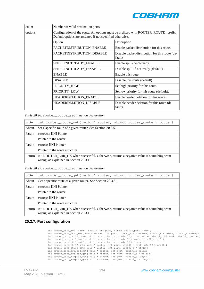
RCC-UMMay 2020, Version 1.3-rc8
134 www.cobham.com/gaisler
count Number of valid destination ports.
Configuration of the route. All options must be prefixed with ROUTER_ROUTE_ prefix.Default options are assumed if not specified otherwise.
Option Description
PACKETDISTRIBUTION_ENABLE Enable packet distribution for this route.
PACKETDISTRIBUTION_DISABLE Disable packet distribution for this route (de-fault).
SPILLIFNOTREADY_ENABLE Enable spill-if-not-ready.
SPILLIFNOTREADY_DISABLE Disable spill-if-not-ready (default).
ENABLE Enable this route.
DISABLE Disable this route (default).
PRIORITY_HIGH Set high priority for this route.
PRIORITY_LOW Set low priority for this route (default).
HEADERDELETION_ENABLE Enable header deletion for this route.
options
HEADERDELETION_DISABLE Disable header deletion for this route (de-fault).
Table 20.26. router_route_set function declaration
Proto int router_route_set( void * router, struct router_route * route )
About Set a specific route of a given router. See Section 20.3.5.
router [IN] PointerParam
Pointer to the router.
route [IN] PointerParam
Pointer to the route structure.
Return int. ROUTER_ERR_OK when successful. Otherwise, returns a negative value if something wentwrong, as explained in Section 20.3.1.
Table 20.27. router_route_get function declaration
Proto int router_route_get( void * router, struct router_route * route )
About Get a specific route of a given router. See Section 20.3.5.
router [IN] PointerParam
Pointer to the router.
route [IN] PointerParam
Pointer to the route structure.
Return int. ROUTER_ERR_OK when successful. Otherwise, returns a negative value if something wentwrong, as explained in Section 20.3.1.
20.3.7. Port configuration
int router_port_ioc( void * router, int port, struct router_port * cfg ) int router_port_ctrl_rmw(void * router, int port, uint32_t * oldvalue, uint32_t bitmask, uint32_t value); int router_port_ctrl2_rmw(void * router, int port, uint32_t * oldvalue, uint32_t bitmask, uint32_t value); int router_port_ctrl_set( void * router, int port, uint32_t mask, uint32_t ctrl ) int router_port_ctrl_get( void * router, int port, uint32_t * ctrl ) int router_port_ctrl2_set( void * router, int port, uint32_t mask, uint32_t ctrl2 ) int router_port_ctrl2_get( void * router, int port, uint32_t * ctrl2 ) int router_port_treload_set( void * router, int port, uint32_t reload ) int router_port_treload_get( void * router, int port, uint32_t * reload ) int router_port_maxplen_set( void * router, int port, uint32_t length ) int router_port_maxplen_get( void * router, int port, uint32_t * length )
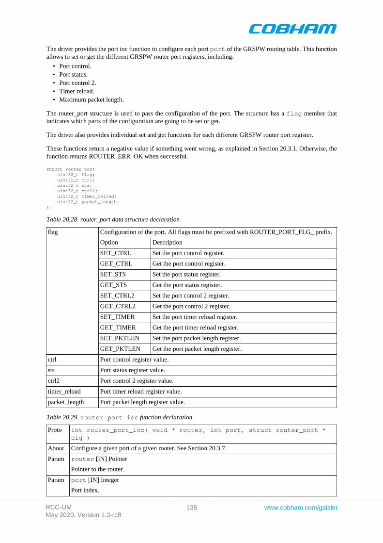
RCC-UMMay 2020, Version 1.3-rc8
135 www.cobham.com/gaisler
The driver provides the port ioc function to configure each port port of the GRSPW routing table. This functionallows to set or get the different GRSPW router port registers, including:
• Port control.• Port status.• Port control 2.• Timer reload.• Maximum packet length.
The router_port structure is used to pass the configuration of the port. The structure has a flag member thatindicates which parts of the configuration are going to be set or get.
The driver also provides individual set and get functions for each different GRSPW router port register.
These functions return a negative value if something went wrong, as explained in Section 20.3.1. Otherwise, thefunction returns ROUTER_ERR_OK when successful.
struct router_port { uint32_t flag; uint32_t ctrl; uint32_t sts; uint32_t ctrl2; uint32_t timer_reload; uint32_t packet_length;};
Table 20.28. router_port data structure declaration
Configuration of the port. All flags must be prefixed with ROUTER_PORT_FLG_ prefix.
Option Description
SET_CTRL Set the port control register.
GET_CTRL Get the port control register.
SET_STS Set the port status register.
GET_STS Get the port status register.
SET_CTRL2 Set the port control 2 register.
GET_CTRL2 Get the port control 2 register.
SET_TIMER Set the port timer reload register.
GET_TIMER Get the port timer reload register.
SET_PKTLEN Set the port packet length register.
flag
GET_PKTLEN Get the port packet length register.
ctrl Port control register value.
sts Port status register value.
ctrl2 Port control 2 register value.
timer_reload Port timer reload register value.
packet_length Port packet length register value.
Table 20.29. router_port_ioc function declaration
Proto int router_port_ioc( void * router, int port, struct router_port *cfg )
About Configure a given port of a given router. See Section 20.3.7.
router [IN] PointerParam
Pointer to the router.
port [IN] IntegerParam
Port index.
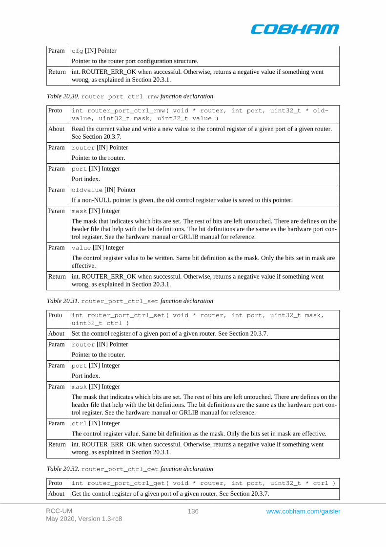
RCC-UMMay 2020, Version 1.3-rc8
136 www.cobham.com/gaisler
cfg [IN] PointerParam
Pointer to the router port configuration structure.
Return int. ROUTER_ERR_OK when successful. Otherwise, returns a negative value if something wentwrong, as explained in Section 20.3.1.
Table 20.30. router_port_ctrl_rmw function declaration
Proto int router_port_ctrl_rmw( void * router, int port, uint32_t * old-value, uint32_t mask, uint32_t value )
About Read the current value and write a new value to the control register of a given port of a given router.See Section 20.3.7.
router [IN] PointerParam
Pointer to the router.
port [IN] IntegerParam
Port index.
oldvalue [IN] PointerParam
If a non-NULL pointer is given, the old control register value is saved to this pointer.
mask [IN] IntegerParam
The mask that indicates which bits are set. The rest of bits are left untouched. There are defines on theheader file that help with the bit definitions. The bit definitions are the same as the hardware port con-trol register. See the hardware manual or GRLIB manual for reference.
value [IN] IntegerParam
The control register value to be written. Same bit definition as the mask. Only the bits set in mask areeffective.
Return int. ROUTER_ERR_OK when successful. Otherwise, returns a negative value if something wentwrong, as explained in Section 20.3.1.
Table 20.31. router_port_ctrl_set function declaration
Proto int router_port_ctrl_set( void * router, int port, uint32_t mask,uint32_t ctrl )
About Set the control register of a given port of a given router. See Section 20.3.7.
router [IN] PointerParam
Pointer to the router.
port [IN] IntegerParam
Port index.
mask [IN] IntegerParam
The mask that indicates which bits are set. The rest of bits are left untouched. There are defines on theheader file that help with the bit definitions. The bit definitions are the same as the hardware port con-trol register. See the hardware manual or GRLIB manual for reference.
ctrl [IN] IntegerParam
The control register value. Same bit definition as the mask. Only the bits set in mask are effective.
Return int. ROUTER_ERR_OK when successful. Otherwise, returns a negative value if something wentwrong, as explained in Section 20.3.1.
Table 20.32. router_port_ctrl_get function declaration
Proto int router_port_ctrl_get( void * router, int port, uint32_t * ctrl )
About Get the control register of a given port of a given router. See Section 20.3.7.
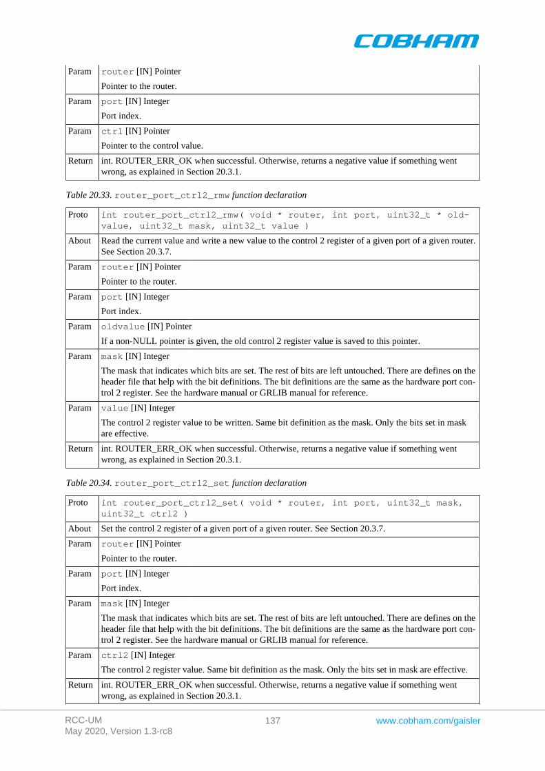
RCC-UMMay 2020, Version 1.3-rc8
137 www.cobham.com/gaisler
router [IN] PointerParam
Pointer to the router.
port [IN] IntegerParam
Port index.
ctrl [IN] PointerParam
Pointer to the control value.
Return int. ROUTER_ERR_OK when successful. Otherwise, returns a negative value if something wentwrong, as explained in Section 20.3.1.
Table 20.33. router_port_ctrl2_rmw function declaration
Proto int router_port_ctrl2_rmw( void * router, int port, uint32_t * old-value, uint32_t mask, uint32_t value )
About Read the current value and write a new value to the control 2 register of a given port of a given router.See Section 20.3.7.
router [IN] PointerParam
Pointer to the router.
port [IN] IntegerParam
Port index.
oldvalue [IN] PointerParam
If a non-NULL pointer is given, the old control 2 register value is saved to this pointer.
mask [IN] IntegerParam
The mask that indicates which bits are set. The rest of bits are left untouched. There are defines on theheader file that help with the bit definitions. The bit definitions are the same as the hardware port con-trol 2 register. See the hardware manual or GRLIB manual for reference.
value [IN] IntegerParam
The control 2 register value to be written. Same bit definition as the mask. Only the bits set in maskare effective.
Return int. ROUTER_ERR_OK when successful. Otherwise, returns a negative value if something wentwrong, as explained in Section 20.3.1.
Table 20.34. router_port_ctrl2_set function declaration
Proto int router_port_ctrl2_set( void * router, int port, uint32_t mask,uint32_t ctrl2 )
About Set the control 2 register of a given port of a given router. See Section 20.3.7.
router [IN] PointerParam
Pointer to the router.
port [IN] IntegerParam
Port index.
mask [IN] IntegerParam
The mask that indicates which bits are set. The rest of bits are left untouched. There are defines on theheader file that help with the bit definitions. The bit definitions are the same as the hardware port con-trol 2 register. See the hardware manual or GRLIB manual for reference.
ctrl2 [IN] IntegerParam
The control 2 register value. Same bit definition as the mask. Only the bits set in mask are effective.
Return int. ROUTER_ERR_OK when successful. Otherwise, returns a negative value if something wentwrong, as explained in Section 20.3.1.
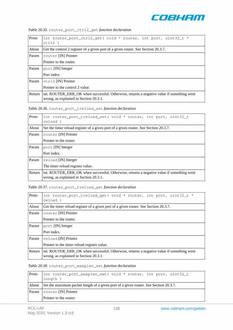
RCC-UMMay 2020, Version 1.3-rc8
138 www.cobham.com/gaisler
Table 20.35. router_port_ctrl2_get function declaration
Proto int router_port_ctrl2_get( void * router, int port, uint32_t *ctrl2 )
About Get the control 2 register of a given port of a given router. See Section 20.3.7.
router [IN] PointerParam
Pointer to the router.
port [IN] IntegerParam
Port index.
ctrl2 [IN] PointerParam
Pointer to the control 2 value.
Return int. ROUTER_ERR_OK when successful. Otherwise, returns a negative value if something wentwrong, as explained in Section 20.3.1.
Table 20.36. router_port_treload_set function declaration
Proto int router_port_treload_set( void * router, int port, uint32_treload )
About Set the timer reload register of a given port of a given router. See Section 20.3.7.
router [IN] PointerParam
Pointer to the router.
port [IN] IntegerParam
Port index.
reload [IN] IntegerParam
The timer reload register value.
Return int. ROUTER_ERR_OK when successful. Otherwise, returns a negative value if something wentwrong, as explained in Section 20.3.1.
Table 20.37. router_port_treload_get function declaration
Proto int router_port_treload_get( void * router, int port, uint32_t *reload )
About Get the timer reload register of a given port of a given router. See Section 20.3.7.
router [IN] PointerParam
Pointer to the router.
port [IN] IntegerParam
Port index.
reload [IN] PointerParam
Pointer to the timer reload register value.
Return int. ROUTER_ERR_OK when successful. Otherwise, returns a negative value if something wentwrong, as explained in Section 20.3.1.
Table 20.38. router_port_maxplen_set function declaration
Proto int router_port_maxplen_set( void * router, int port, uint32_tlength )
About Set the maximum packet length of a given port of a given router. See Section 20.3.7.
router [IN] PointerParam
Pointer to the router.
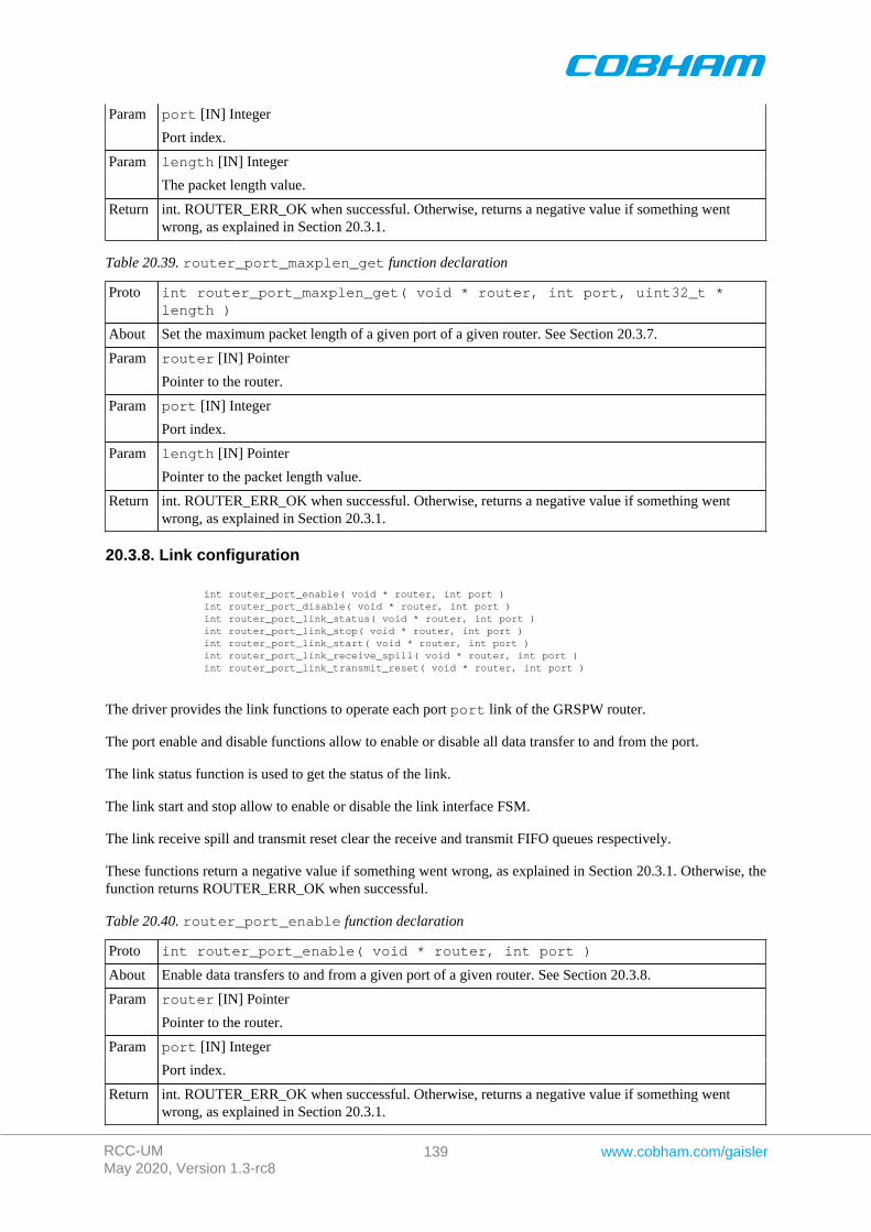
RCC-UMMay 2020, Version 1.3-rc8
139 www.cobham.com/gaisler
port [IN] IntegerParam
Port index.
length [IN] IntegerParam
The packet length value.
Return int. ROUTER_ERR_OK when successful. Otherwise, returns a negative value if something wentwrong, as explained in Section 20.3.1.
Table 20.39. router_port_maxplen_get function declaration
Proto int router_port_maxplen_get( void * router, int port, uint32_t *length )
About Set the maximum packet length of a given port of a given router. See Section 20.3.7.
router [IN] PointerParam
Pointer to the router.
port [IN] IntegerParam
Port index.
length [IN] PointerParam
Pointer to the packet length value.
Return int. ROUTER_ERR_OK when successful. Otherwise, returns a negative value if something wentwrong, as explained in Section 20.3.1.
20.3.8. Link configuration
int router_port_enable( void * router, int port ) int router_port_disable( void * router, int port ) int router_port_link_status( void * router, int port ) int router_port_link_stop( void * router, int port ) int router_port_link_start( void * router, int port ) int router_port_link_receive_spill( void * router, int port ) int router_port_link_transmit_reset( void * router, int port )
The driver provides the link functions to operate each port port link of the GRSPW router.
The port enable and disable functions allow to enable or disable all data transfer to and from the port.
The link status function is used to get the status of the link.
The link start and stop allow to enable or disable the link interface FSM.
The link receive spill and transmit reset clear the receive and transmit FIFO queues respectively.
These functions return a negative value if something went wrong, as explained in Section 20.3.1. Otherwise, thefunction returns ROUTER_ERR_OK when successful.
Table 20.40. router_port_enable function declaration
Proto int router_port_enable( void * router, int port )
About Enable data transfers to and from a given port of a given router. See Section 20.3.8.
router [IN] PointerParam
Pointer to the router.
port [IN] IntegerParam
Port index.
Return int. ROUTER_ERR_OK when successful. Otherwise, returns a negative value if something wentwrong, as explained in Section 20.3.1.
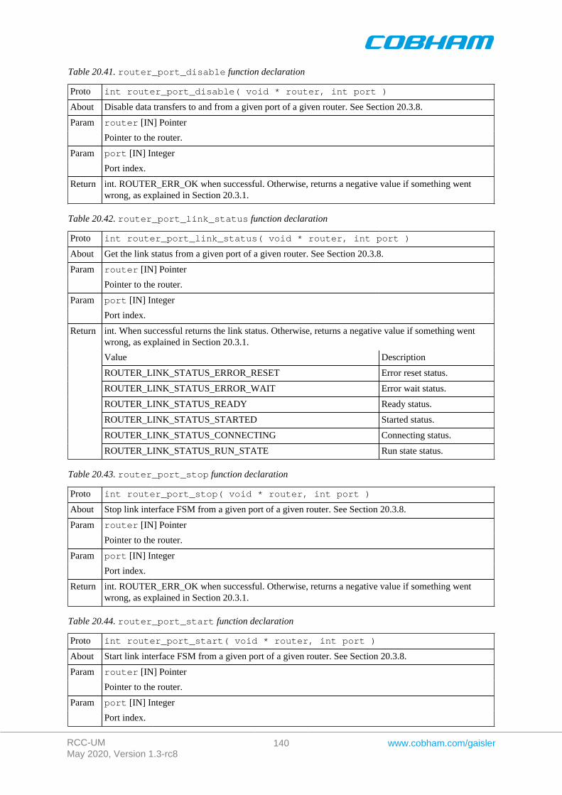
RCC-UMMay 2020, Version 1.3-rc8
140 www.cobham.com/gaisler
Table 20.41. router_port_disable function declaration
Proto int router_port_disable( void * router, int port )
About Disable data transfers to and from a given port of a given router. See Section 20.3.8.
router [IN] PointerParam
Pointer to the router.
port [IN] IntegerParam
Port index.
Return int. ROUTER_ERR_OK when successful. Otherwise, returns a negative value if something wentwrong, as explained in Section 20.3.1.
Table 20.42. router_port_link_status function declaration
Proto int router_port_link_status( void * router, int port )
About Get the link status from a given port of a given router. See Section 20.3.8.
router [IN] PointerParam
Pointer to the router.
port [IN] IntegerParam
Port index.
int. When successful returns the link status. Otherwise, returns a negative value if something wentwrong, as explained in Section 20.3.1.
Value Description
ROUTER_LINK_STATUS_ERROR_RESET Error reset status.
ROUTER_LINK_STATUS_ERROR_WAIT Error wait status.
ROUTER_LINK_STATUS_READY Ready status.
ROUTER_LINK_STATUS_STARTED Started status.
ROUTER_LINK_STATUS_CONNECTING Connecting status.
Return
ROUTER_LINK_STATUS_RUN_STATE Run state status.
Table 20.43. router_port_stop function declaration
Proto int router_port_stop( void * router, int port )
About Stop link interface FSM from a given port of a given router. See Section 20.3.8.
router [IN] PointerParam
Pointer to the router.
port [IN] IntegerParam
Port index.
Return int. ROUTER_ERR_OK when successful. Otherwise, returns a negative value if something wentwrong, as explained in Section 20.3.1.
Table 20.44. router_port_start function declaration
Proto int router_port_start( void * router, int port )
About Start link interface FSM from a given port of a given router. See Section 20.3.8.
router [IN] PointerParam
Pointer to the router.
port [IN] IntegerParam
Port index.
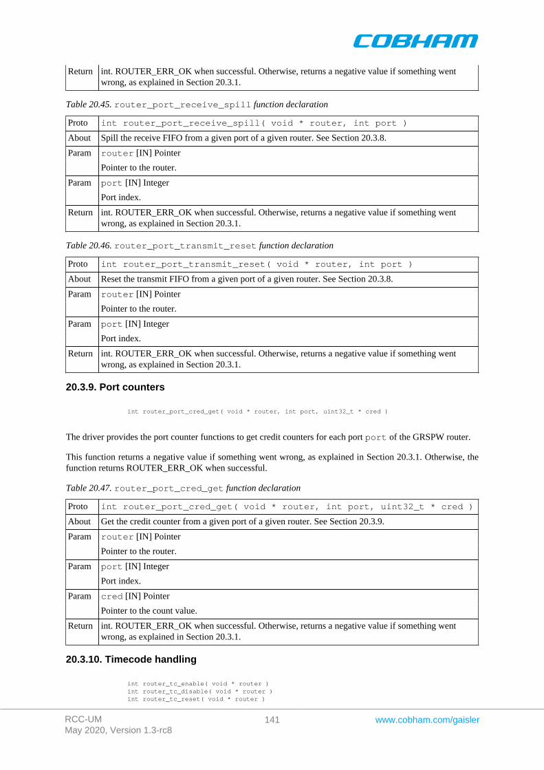
RCC-UMMay 2020, Version 1.3-rc8
141 www.cobham.com/gaisler
Return int. ROUTER_ERR_OK when successful. Otherwise, returns a negative value if something wentwrong, as explained in Section 20.3.1.
Table 20.45. router_port_receive_spill function declaration
Proto int router_port_receive_spill( void * router, int port )
About Spill the receive FIFO from a given port of a given router. See Section 20.3.8.
router [IN] PointerParam
Pointer to the router.
port [IN] IntegerParam
Port index.
Return int. ROUTER_ERR_OK when successful. Otherwise, returns a negative value if something wentwrong, as explained in Section 20.3.1.
Table 20.46. router_port_transmit_reset function declaration
Proto int router_port_transmit_reset( void * router, int port )
About Reset the transmit FIFO from a given port of a given router. See Section 20.3.8.
router [IN] PointerParam
Pointer to the router.
port [IN] IntegerParam
Port index.
Return int. ROUTER_ERR_OK when successful. Otherwise, returns a negative value if something wentwrong, as explained in Section 20.3.1.
20.3.9. Port counters
int router_port_cred_get( void * router, int port, uint32_t * cred )
The driver provides the port counter functions to get credit counters for each port port of the GRSPW router.
This function returns a negative value if something went wrong, as explained in Section 20.3.1. Otherwise, thefunction returns ROUTER_ERR_OK when successful.
Table 20.47. router_port_cred_get function declaration
Proto int router_port_cred_get( void * router, int port, uint32_t * cred )
About Get the credit counter from a given port of a given router. See Section 20.3.9.
router [IN] PointerParam
Pointer to the router.
port [IN] IntegerParam
Port index.
cred [IN] PointerParam
Pointer to the count value.
Return int. ROUTER_ERR_OK when successful. Otherwise, returns a negative value if something wentwrong, as explained in Section 20.3.1.
20.3.10. Timecode handling
int router_tc_enable( void * router ) int router_tc_disable( void * router ) int router_tc_reset( void * router )
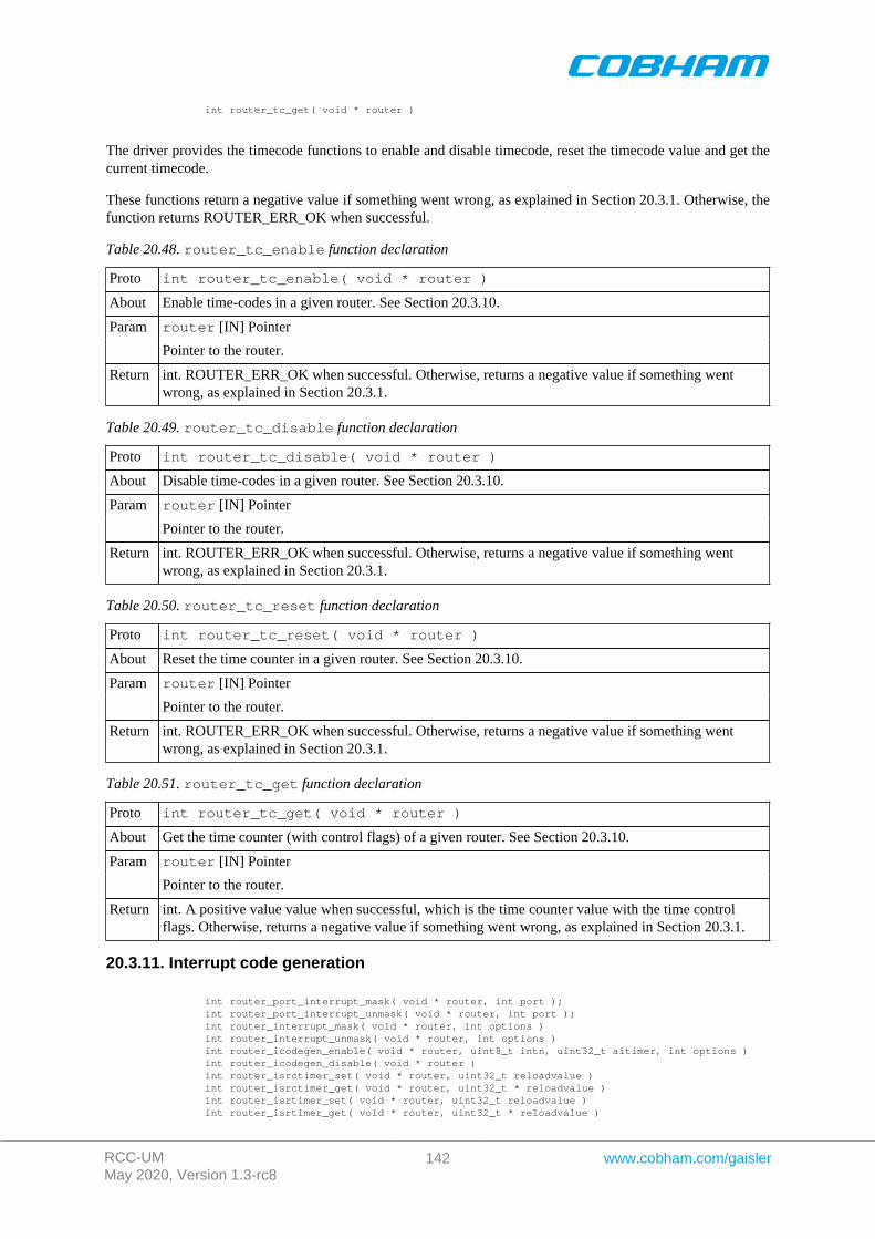
RCC-UMMay 2020, Version 1.3-rc8
142 www.cobham.com/gaisler
int router_tc_get( void * router )
The driver provides the timecode functions to enable and disable timecode, reset the timecode value and get thecurrent timecode.
These functions return a negative value if something went wrong, as explained in Section 20.3.1. Otherwise, thefunction returns ROUTER_ERR_OK when successful.
Table 20.48. router_tc_enable function declaration
Proto int router_tc_enable( void * router )
About Enable time-codes in a given router. See Section 20.3.10.
router [IN] PointerParam
Pointer to the router.
Return int. ROUTER_ERR_OK when successful. Otherwise, returns a negative value if something wentwrong, as explained in Section 20.3.1.
Table 20.49. router_tc_disable function declaration
Proto int router_tc_disable( void * router )
About Disable time-codes in a given router. See Section 20.3.10.
router [IN] PointerParam
Pointer to the router.
Return int. ROUTER_ERR_OK when successful. Otherwise, returns a negative value if something wentwrong, as explained in Section 20.3.1.
Table 20.50. router_tc_reset function declaration
Proto int router_tc_reset( void * router )
About Reset the time counter in a given router. See Section 20.3.10.
router [IN] PointerParam
Pointer to the router.
Return int. ROUTER_ERR_OK when successful. Otherwise, returns a negative value if something wentwrong, as explained in Section 20.3.1.
Table 20.51. router_tc_get function declaration
Proto int router_tc_get( void * router )
About Get the time counter (with control flags) of a given router. See Section 20.3.10.
router [IN] PointerParam
Pointer to the router.
Return int. A positive value value when successful, which is the time counter value with the time controlflags. Otherwise, returns a negative value if something went wrong, as explained in Section 20.3.1.
20.3.11. Interrupt code generation
int router_port_interrupt_mask( void * router, int port ); int router_port_interrupt_unmask( void * router, int port ); int router_interrupt_mask( void * router, int options ) int router_interrupt_unmask( void * router, int options ) int router_icodegen_enable( void * router, uint8_t intn, uint32_t aitimer, int options ) int router_icodegen_disable( void * router ) int router_isrctimer_set( void * router, uint32_t reloadvalue ) int router_isrctimer_get( void * router, uint32_t * reloadvalue ) int router_isrtimer_set( void * router, uint32_t reloadvalue ) int router_isrtimer_get( void * router, uint32_t * reloadvalue )
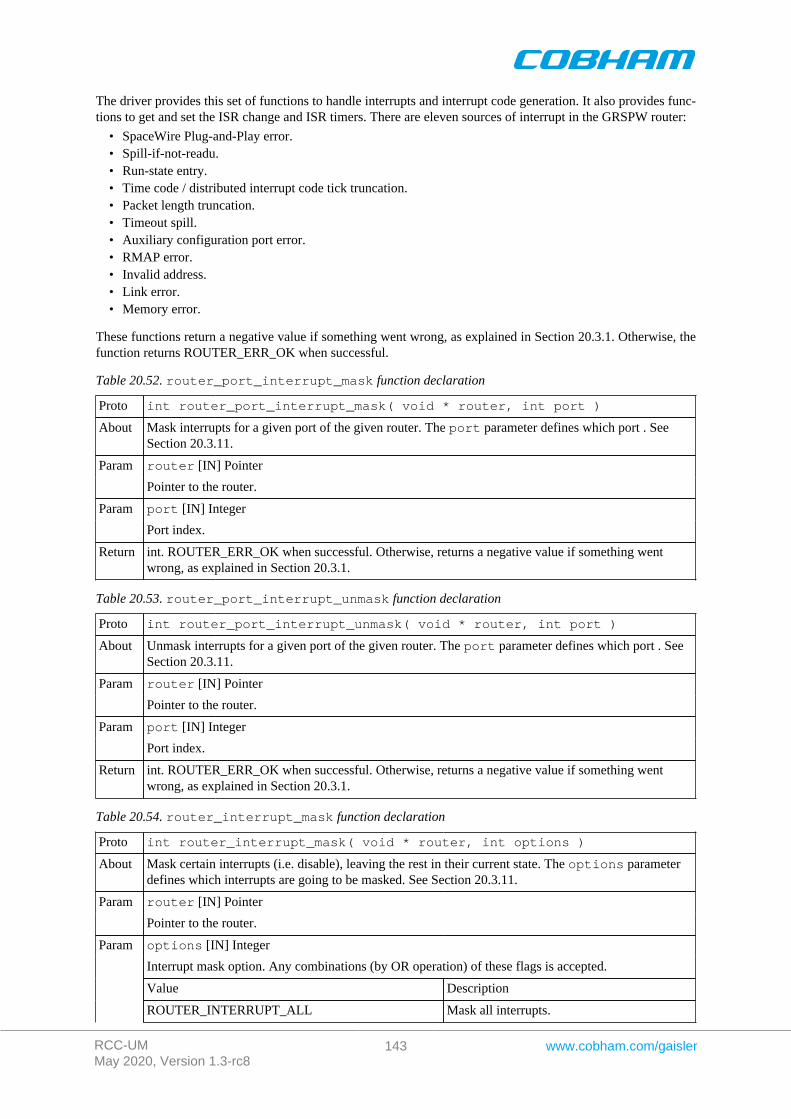
RCC-UMMay 2020, Version 1.3-rc8
143 www.cobham.com/gaisler
The driver provides this set of functions to handle interrupts and interrupt code generation. It also provides func-tions to get and set the ISR change and ISR timers. There are eleven sources of interrupt in the GRSPW router:
• SpaceWire Plug-and-Play error.• Spill-if-not-readu.• Run-state entry.• Time code / distributed interrupt code tick truncation.• Packet length truncation.• Timeout spill.• Auxiliary configuration port error.• RMAP error.• Invalid address.• Link error.• Memory error.
These functions return a negative value if something went wrong, as explained in Section 20.3.1. Otherwise, thefunction returns ROUTER_ERR_OK when successful.
Table 20.52. router_port_interrupt_mask function declaration
Proto int router_port_interrupt_mask( void * router, int port )
About Mask interrupts for a given port of the given router. The port parameter defines which port . SeeSection 20.3.11.
router [IN] PointerParam
Pointer to the router.
port [IN] IntegerParam
Port index.
Return int. ROUTER_ERR_OK when successful. Otherwise, returns a negative value if something wentwrong, as explained in Section 20.3.1.
Table 20.53. router_port_interrupt_unmask function declaration
Proto int router_port_interrupt_unmask( void * router, int port )
About Unmask interrupts for a given port of the given router. The port parameter defines which port . SeeSection 20.3.11.
router [IN] PointerParam
Pointer to the router.
port [IN] IntegerParam
Port index.
Return int. ROUTER_ERR_OK when successful. Otherwise, returns a negative value if something wentwrong, as explained in Section 20.3.1.
Table 20.54. router_interrupt_mask function declaration
Proto int router_interrupt_mask( void * router, int options )
About Mask certain interrupts (i.e. disable), leaving the rest in their current state. The options parameterdefines which interrupts are going to be masked. See Section 20.3.11.
router [IN] PointerParam
Pointer to the router.
options [IN] Integer
Interrupt mask option. Any combinations (by OR operation) of these flags is accepted.
Value Description
Param
ROUTER_INTERRUPT_ALL Mask all interrupts.
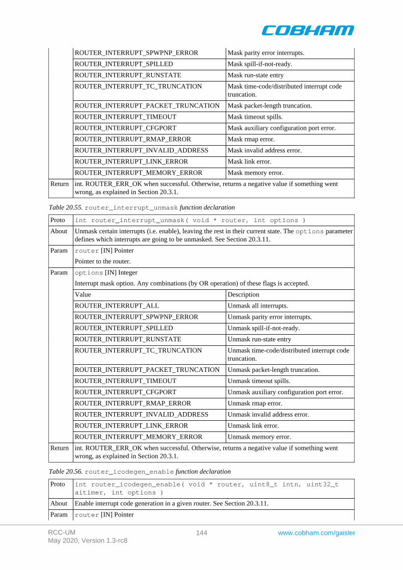
RCC-UMMay 2020, Version 1.3-rc8
144 www.cobham.com/gaisler
ROUTER_INTERRUPT_SPWPNP_ERROR Mask parity error interrupts.
ROUTER_INTERRUPT_SPILLED Mask spill-if-not-ready.
ROUTER_INTERRUPT_RUNSTATE Mask run-state entry
ROUTER_INTERRUPT_TC_TRUNCATION Mask time-code/distributed interrupt codetruncation.
ROUTER_INTERRUPT_PACKET_TRUNCATION Mask packet-length truncation.
ROUTER_INTERRUPT_TIMEOUT Mask timeout spills.
ROUTER_INTERRUPT_CFGPORT Mask auxiliary configuration port error.
ROUTER_INTERRUPT_RMAP_ERROR Mask rmap error.
ROUTER_INTERRUPT_INVALID_ADDRESS Mask invalid address error.
ROUTER_INTERRUPT_LINK_ERROR Mask link error.
ROUTER_INTERRUPT_MEMORY_ERROR Mask memory error.
Return int. ROUTER_ERR_OK when successful. Otherwise, returns a negative value if something wentwrong, as explained in Section 20.3.1.
Table 20.55. router_interrupt_unmask function declaration
Proto int router_interrupt_unmask( void * router, int options )
About Unmask certain interrupts (i.e. enable), leaving the rest in their current state. The options parameterdefines which interrupts are going to be unmasked. See Section 20.3.11.
router [IN] PointerParam
Pointer to the router.
options [IN] Integer
Interrupt mask option. Any combinations (by OR operation) of these flags is accepted.
Value Description
ROUTER_INTERRUPT_ALL Unmask all interrupts.
ROUTER_INTERRUPT_SPWPNP_ERROR Unmask parity error interrupts.
ROUTER_INTERRUPT_SPILLED Unmask spill-if-not-ready.
ROUTER_INTERRUPT_RUNSTATE Unmask run-state entry
ROUTER_INTERRUPT_TC_TRUNCATION Unmask time-code/distributed interrupt codetruncation.
ROUTER_INTERRUPT_PACKET_TRUNCATION Unmask packet-length truncation.
ROUTER_INTERRUPT_TIMEOUT Unmask timeout spills.
ROUTER_INTERRUPT_CFGPORT Unmask auxiliary configuration port error.
ROUTER_INTERRUPT_RMAP_ERROR Unmask rmap error.
ROUTER_INTERRUPT_INVALID_ADDRESS Unmask invalid address error.
ROUTER_INTERRUPT_LINK_ERROR Unmask link error.
Param
ROUTER_INTERRUPT_MEMORY_ERROR Unmask memory error.
Return int. ROUTER_ERR_OK when successful. Otherwise, returns a negative value if something wentwrong, as explained in Section 20.3.1.
Table 20.56. router_icodegen_enable function declaration
Proto int router_icodegen_enable( void * router, uint8_t intn, uint32_taitimer, int options )
About Enable interrupt code generation in a given router. See Section 20.3.11.
Param router [IN] Pointer
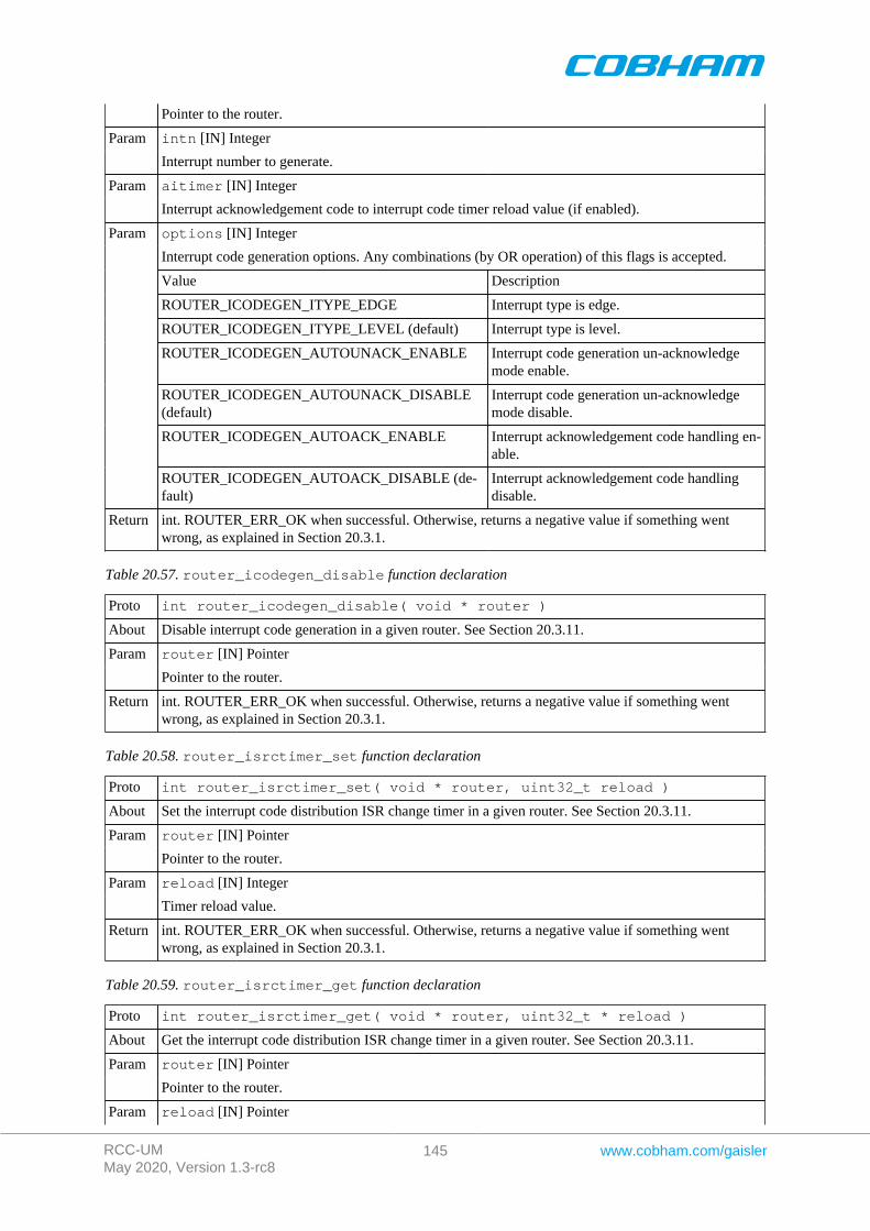
RCC-UMMay 2020, Version 1.3-rc8
145 www.cobham.com/gaisler
Pointer to the router.
intn [IN] IntegerParam
Interrupt number to generate.
aitimer [IN] IntegerParam
Interrupt acknowledgement code to interrupt code timer reload value (if enabled).
options [IN] Integer
Interrupt code generation options. Any combinations (by OR operation) of this flags is accepted.
Value Description
ROUTER_ICODEGEN_ITYPE_EDGE Interrupt type is edge.
ROUTER_ICODEGEN_ITYPE_LEVEL (default) Interrupt type is level.
ROUTER_ICODEGEN_AUTOUNACK_ENABLE Interrupt code generation un-acknowledgemode enable.
ROUTER_ICODEGEN_AUTOUNACK_DISABLE(default)
Interrupt code generation un-acknowledgemode disable.
ROUTER_ICODEGEN_AUTOACK_ENABLE Interrupt acknowledgement code handling en-able.
Param
ROUTER_ICODEGEN_AUTOACK_DISABLE (de-fault)
Interrupt acknowledgement code handlingdisable.
Return int. ROUTER_ERR_OK when successful. Otherwise, returns a negative value if something wentwrong, as explained in Section 20.3.1.
Table 20.57. router_icodegen_disable function declaration
Proto int router_icodegen_disable( void * router )
About Disable interrupt code generation in a given router. See Section 20.3.11.
router [IN] PointerParam
Pointer to the router.
Return int. ROUTER_ERR_OK when successful. Otherwise, returns a negative value if something wentwrong, as explained in Section 20.3.1.
Table 20.58. router_isrctimer_set function declaration
Proto int router_isrctimer_set( void * router, uint32_t reload )
About Set the interrupt code distribution ISR change timer in a given router. See Section 20.3.11.
router [IN] PointerParam
Pointer to the router.
reload [IN] IntegerParam
Timer reload value.
Return int. ROUTER_ERR_OK when successful. Otherwise, returns a negative value if something wentwrong, as explained in Section 20.3.1.
Table 20.59. router_isrctimer_get function declaration
Proto int router_isrctimer_get( void * router, uint32_t * reload )
About Get the interrupt code distribution ISR change timer in a given router. See Section 20.3.11.
router [IN] PointerParam
Pointer to the router.
Param reload [IN] Pointer
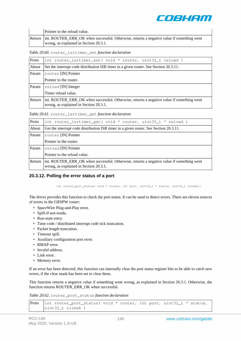
RCC-UMMay 2020, Version 1.3-rc8
146 www.cobham.com/gaisler
Pointer to the reload value.
Return int. ROUTER_ERR_OK when successful. Otherwise, returns a negative value if something wentwrong, as explained in Section 20.3.1.
Table 20.60. router_isrtimer_set function declaration
Proto int router_isrtimer_set( void * router, uint32_t reload )
About Set the interrupt code distribution ISR timer in a given router. See Section 20.3.11.
router [IN] PointerParam
Pointer to the router.
reload [IN] IntegerParam
Timer reload value.
Return int. ROUTER_ERR_OK when successful. Otherwise, returns a negative value if something wentwrong, as explained in Section 20.3.1.
Table 20.61. router_isrtimer_get function declaration
Proto int router_isrtimer_get( void * router, uint32_t * reload )
About Get the interrupt code distribution ISR timer in a given router. See Section 20.3.11.
router [IN] PointerParam
Pointer to the router.
reload [IN] PointerParam
Pointer to the reload value.
Return int. ROUTER_ERR_OK when successful. Otherwise, returns a negative value if something wentwrong, as explained in Section 20.3.1.
20.3.12. Polling the error status of a port
int router_port_status( void * router, int port, uint32_t * status, uint32_t clrmsk);
The driver provides this function to check the port status. It can be used to detect errors. There are eleven sourcesof errors in the GRSPW router:
• SpaceWire Plug-and-Play error.• Spill-if-not-readu.• Run-state entry.• Time code / distributed interrupt code tick truncation.• Packet length truncation.• Timeout spill.• Auxiliary configuration port error.• RMAP error.• Invalid address.• Link error.• Memory error.
If an error has been detected, this function can internally clear the port status register bits to be able to catch newerrors, if the clear mask has been set to clear them.
This function returns a negative value if something went wrong, as explained in Section 20.3.1. Otherwise, thefunction returns ROUTER_ERR_OK when successful.
Table 20.62. router_port_status function declaration
Proto int router_port_status( void * router, int port, uint32_t * status,uint32_t clrmsk )
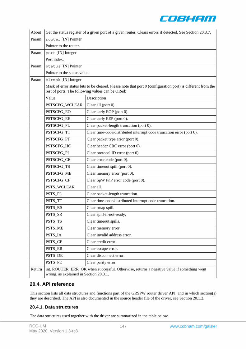
RCC-UMMay 2020, Version 1.3-rc8
147 www.cobham.com/gaisler
About Get the status register of a given port of a given router. Clears errors if detected. See Section 20.3.7.
router [IN] PointerParam
Pointer to the router.
port [IN] IntegerParam
Port index.
status [IN] PointerParam
Pointer to the status value.
clrmsk [IN] Integer
Mask of error status bits to be cleared. Please note that port 0 (configuration port) is different from therest of ports. The following values can be ORed:
Value Description
PSTSCFG_WCLEAR Clear all (port 0).
PSTSCFG_EO Clear early EOP (port 0).
PSTSCFG_EE Clear early EEP (port 0).
PSTSCFG_PL Clear packet-length truncation (port 0).
PSTSCFG_TT Clear time-code/distributed interrupt code truncation error (port 0).
PSTSCFG_PT Clear packet type error (port 0).
PSTSCFG_HC Clear header CRC error (port 0).
PSTSCFG_PI Clear protocol ID error (port 0).
PSTSCFG_CE Clear error code (port 0).
PSTSCFG_TS Clear timeout spill (port 0).
PSTSCFG_ME Clear memory error (port 0).
PSTSCFG_CP Clear SpW PnP error code (port 0).
PSTS_WCLEAR Clear all.
PSTS_PL Clear packet-length truncation.
PSTS_TT Clear time-code/distributed interrupt code truncation.
PSTS_RS Clear rmap spill.
PSTS_SR Clear spill-if-not-ready.
PSTS_TS Clear timeout spills.
PSTS_ME Clear memory error.
PSTS_IA Clear invalid address error.
PSTS_CE Clear credit error.
PSTS_ER Clear escape error.
PSTS_DE Clear disconnect error.
Param
PSTS_PE Clear parity error.
Return int. ROUTER_ERR_OK when successful. Otherwise, returns a negative value if something wentwrong, as explained in Section 20.3.1.
20.4. API reference
This section lists all data structures and functions part of the GRSPW router driver API, and in which section(s)they are described. The API is also documented in the source header file of the driver, see Section 20.1.2.
20.4.1. Data structures
The data structures used together with the driver are summarized in the table below.
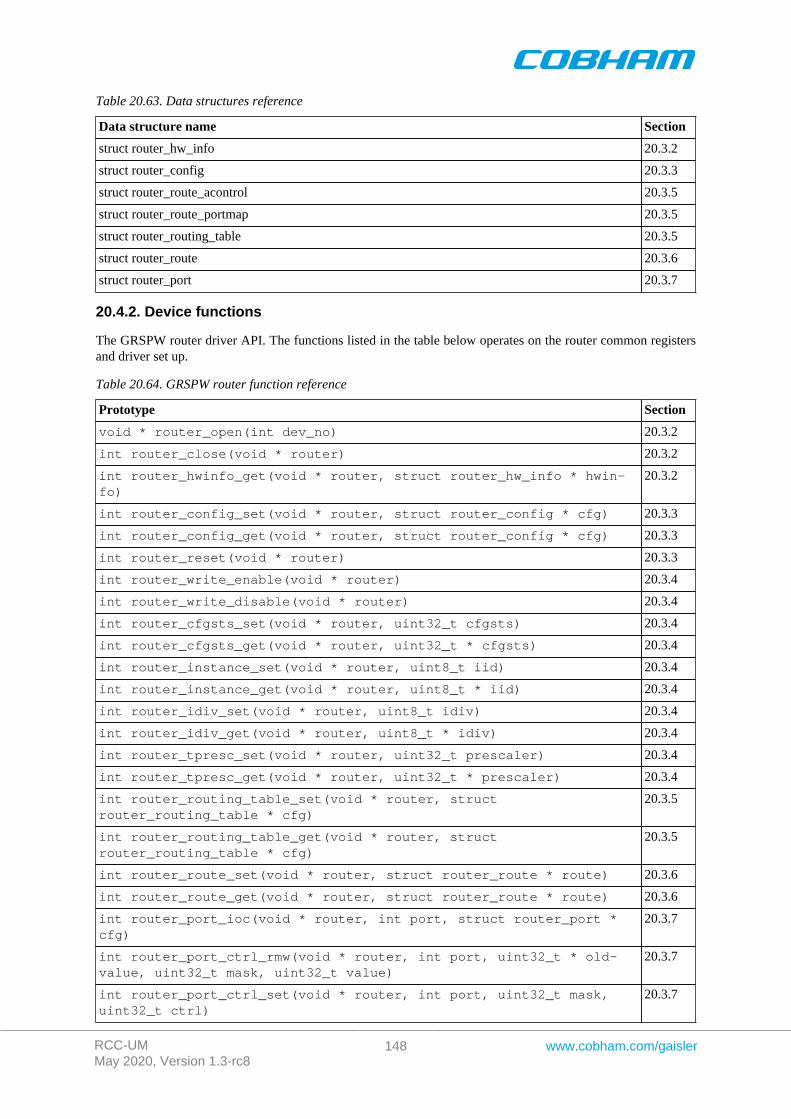
RCC-UMMay 2020, Version 1.3-rc8
148 www.cobham.com/gaisler
Table 20.63. Data structures reference
Data structure name Section
struct router_hw_info 20.3.2
struct router_config 20.3.3
struct router_route_acontrol 20.3.5
struct router_route_portmap 20.3.5
struct router_routing_table 20.3.5
struct router_route 20.3.6
struct router_port 20.3.7
20.4.2. Device functions
The GRSPW router driver API. The functions listed in the table below operates on the router common registersand driver set up.
Table 20.64. GRSPW router function reference
Prototype Section
void * router_open(int dev_no) 20.3.2
int router_close(void * router) 20.3.2
int router_hwinfo_get(void * router, struct router_hw_info * hwin-fo)
20.3.2
int router_config_set(void * router, struct router_config * cfg) 20.3.3
int router_config_get(void * router, struct router_config * cfg) 20.3.3
int router_reset(void * router) 20.3.3
int router_write_enable(void * router) 20.3.4
int router_write_disable(void * router) 20.3.4
int router_cfgsts_set(void * router, uint32_t cfgsts) 20.3.4
int router_cfgsts_get(void * router, uint32_t * cfgsts) 20.3.4
int router_instance_set(void * router, uint8_t iid) 20.3.4
int router_instance_get(void * router, uint8_t * iid) 20.3.4
int router_idiv_set(void * router, uint8_t idiv) 20.3.4
int router_idiv_get(void * router, uint8_t * idiv) 20.3.4
int router_tpresc_set(void * router, uint32_t prescaler) 20.3.4
int router_tpresc_get(void * router, uint32_t * prescaler) 20.3.4
int router_routing_table_set(void * router, structrouter_routing_table * cfg)
20.3.5
int router_routing_table_get(void * router, structrouter_routing_table * cfg)
20.3.5
int router_route_set(void * router, struct router_route * route) 20.3.6
int router_route_get(void * router, struct router_route * route) 20.3.6
int router_port_ioc(void * router, int port, struct router_port *cfg)
20.3.7
int router_port_ctrl_rmw(void * router, int port, uint32_t * old-value, uint32_t mask, uint32_t value)
20.3.7
int router_port_ctrl_set(void * router, int port, uint32_t mask,uint32_t ctrl)
20.3.7
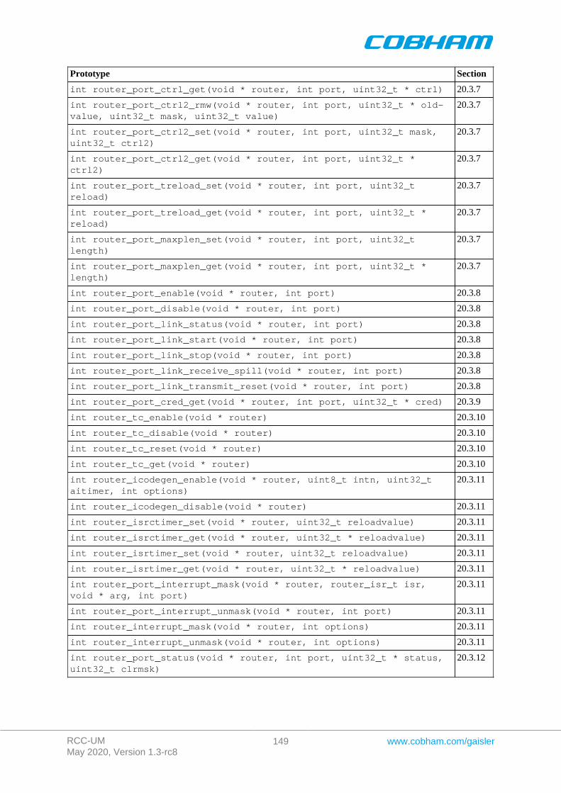
RCC-UMMay 2020, Version 1.3-rc8
149 www.cobham.com/gaisler
Prototype Section
int router_port_ctrl_get(void * router, int port, uint32_t * ctrl) 20.3.7
int router_port_ctrl2_rmw(void * router, int port, uint32_t * old-value, uint32_t mask, uint32_t value)
20.3.7
int router_port_ctrl2_set(void * router, int port, uint32_t mask,uint32_t ctrl2)
20.3.7
int router_port_ctrl2_get(void * router, int port, uint32_t *ctrl2)
20.3.7
int router_port_treload_set(void * router, int port, uint32_treload)
20.3.7
int router_port_treload_get(void * router, int port, uint32_t *reload)
20.3.7
int router_port_maxplen_set(void * router, int port, uint32_tlength)
20.3.7
int router_port_maxplen_get(void * router, int port, uint32_t *length)
20.3.7
int router_port_enable(void * router, int port) 20.3.8
int router_port_disable(void * router, int port) 20.3.8
int router_port_link_status(void * router, int port) 20.3.8
int router_port_link_start(void * router, int port) 20.3.8
int router_port_link_stop(void * router, int port) 20.3.8
int router_port_link_receive_spill(void * router, int port) 20.3.8
int router_port_link_transmit_reset(void * router, int port) 20.3.8
int router_port_cred_get(void * router, int port, uint32_t * cred) 20.3.9
int router_tc_enable(void * router) 20.3.10
int router_tc_disable(void * router) 20.3.10
int router_tc_reset(void * router) 20.3.10
int router_tc_get(void * router) 20.3.10
int router_icodegen_enable(void * router, uint8_t intn, uint32_taitimer, int options)
20.3.11
int router_icodegen_disable(void * router) 20.3.11
int router_isrctimer_set(void * router, uint32_t reloadvalue) 20.3.11
int router_isrctimer_get(void * router, uint32_t * reloadvalue) 20.3.11
int router_isrtimer_set(void * router, uint32_t reloadvalue) 20.3.11
int router_isrtimer_get(void * router, uint32_t * reloadvalue) 20.3.11
int router_port_interrupt_mask(void * router, router_isr_t isr,void * arg, int port)
20.3.11
int router_port_interrupt_unmask(void * router, int port) 20.3.11
int router_interrupt_mask(void * router, int options) 20.3.11
int router_interrupt_unmask(void * router, int options) 20.3.11
int router_port_status(void * router, int port, uint32_t * status,uint32_t clrmsk)
20.3.12
RCC-UMMay 2020, Version 1.3-rc8
150 www.cobham.com/gaisler
Chapter 21. SPWTDP driver
21.1. Introduction
This section describes the SPWTDP driver for SPARC/LEON processors.
21.1.1. Hardware Support
The SPWTDP core hardware interface is documented in the GRIP Core User's manual. The SPWTDP core im-plements the Spacewire time distribution protocol.
21.1.2. Driver sources
The driver sources and definitions are listed in the table below, the path is given relative to the RTEMS sourcetree rtems-5/c/src/lib/libbsp/sparc.
Table 21.1. SPWTDP driver source location
Location Description
shared/include/spwtdp.h SPWTDP user interface definition
.../libbsp/sparc/shared/spw/spwtdp.c SPWTDP driver implementation
21.1.3. Examples
There is a simple example available that uses the SPWTDP driver to measure the latency between two boards.The example is part of the RCC distribution, it can be found under /opt/rtems-5/src/samples/spw/spwtdp/.
21.2. Software design overview
The driver has been implemented using the Driver Manager Framework. The driver provides a kernel functioninterface, an API, rather than implementing a IO system device. The API is SMP safe. The driver contains asemaphore locking mechanism for SMP environments.
21.2.1. Driver usage
The driver provides a set of functions that allow to configure and operate the SPWTDP as initiator or target.
First of all, we need to open the SPWTDP device before using it. If we want to put it at a known state, the SPWTDPdevice can be reset. See Section 21.3.2.
Once the SPWTDP is open, we need to setup the time generation. See Section 21.3.3.
After this, we can configure the SPWTDP device as either initiator or target. We can also configure the distributedinterrupt, SPW time-code synchronization, command control and time-stamping. Once the device is configuredas initiator or target, it can be enabled to start working. See Section 21.3.4.
To check for status and/or events, we cam use the functions in Section 21.3.7, or use interrupt service routines.See Section 21.3.6.
Once the SPWTDP device is working, we can get elapsed times and timestamps. See Section 21.3.5.
When we are finished, we can disable the initiator/target, see Section 21.3.4, and close the SPWTDP device, seeSection 21.3.2.
21.2.2. Initialization
During early initialization when the operating system boots the SPWTDP driver, the driver resets the SPWTDPcore.
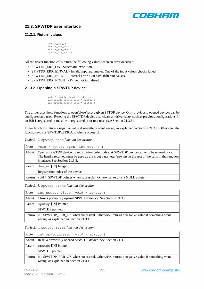
RCC-UMMay 2020, Version 1.3-rc8
151 www.cobham.com/gaisler
21.3. SPWTDP user interface
21.3.1. Return values
SPWTDP_ERR_OK SPWTDP_ERR_EINVAL SPWTDP_ERR_ERROR SPWTDP_ERR_NOINIT
All the driver function calls return the following values when an error occurred:
• SPWTDP_ERR_OK - Successful execution.• SPWTDP_ERR_EINVAL - Invalid input parameter. One of the input values checks failed.• SPWTDP_ERR_ERROR - Internal error. Can have different causes.• SPWTDP_ERR_NOINIT - Driver not initialized.
21.3.2. Opening a SPWTDP device
void * spwtdp_open( int dev_no ) int spwtdp_close( void * spwtdp ) int spwtdp_reset( void * spwtdp )
The driver uses these functions to open/close/reset a given SPTDP device. Only previously opened devices can beconfigured and used. Reseting the SPWTDP device also clears all driver state, such as previous configurations. Ifan ISR is registered, it must be unregistered prior to a reset (see Section 21.3.6).
These functions return a negative value if something went wrong, as explained in Section 21.3.1. Otherwise, thefunction returns SPWTDP_ERR_OK when successful.
Table 21.2. spwtdp_open function declaration
Proto void * spwtdp_open( int dev_no )
About Open a SPWTDP device by registration order index. A SPWTDP device can only be opened once.The handle returned must be used as the input parameter 'spwtdp' in the rest of the calls in the functioninterface. See Section 21.3.2.
dev_no [IN] IntegerParam
Registration index of the device.
Return void *. SPWTDP pointer when successful. Otherwise, returns a NULL pointer.
Table 21.3. spwtdp_close function declaration
Proto int spwtdp_close( void * spwtdp )
About Close a previously opened SPWTDP device. See Section 21.3.2.
spwtdp [IN] PointerParam
SPWTDP pointer.
Return int. SPWTDP_ERR_OK when successful. Otherwise, returns a negative value if something wentwrong, as explained in Section 21.3.1.
Table 21.4. spwtdp_reset function declaration
Proto int spwtdp_reset( void * spwtdp )
About Reset a previously opened SPWTDP device. See Section 21.3.2.
spwtdp [IN] PointerParam
SPWTDP pointer.
Return int. SPWTDP_ERR_OK when successful. Otherwise, returns a negative value if something wentwrong, as explained in Section 21.3.1.
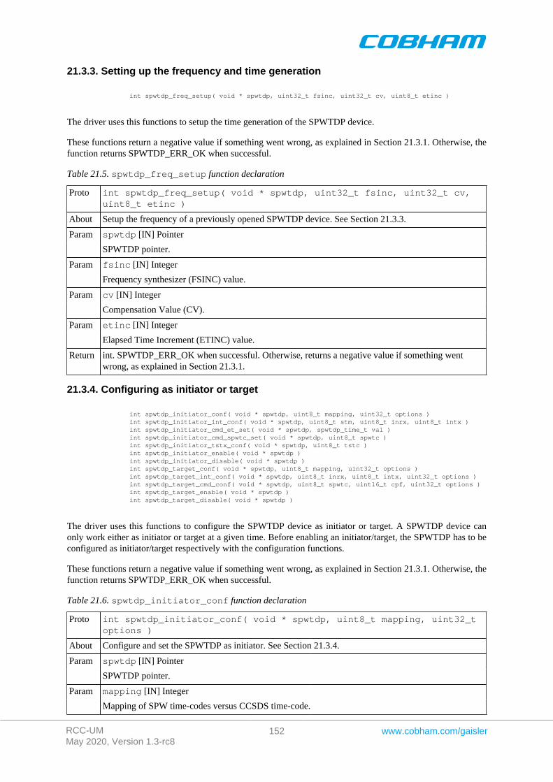
RCC-UMMay 2020, Version 1.3-rc8
152 www.cobham.com/gaisler
21.3.3. Setting up the frequency and time generation
int spwtdp_freq_setup( void * spwtdp, uint32_t fsinc, uint32_t cv, uint8_t etinc )
The driver uses this functions to setup the time generation of the SPWTDP device.
These functions return a negative value if something went wrong, as explained in Section 21.3.1. Otherwise, thefunction returns SPWTDP_ERR_OK when successful.
Table 21.5. spwtdp_freq_setup function declaration
Proto int spwtdp_freq_setup( void * spwtdp, uint32_t fsinc, uint32_t cv,uint8_t etinc )
About Setup the frequency of a previously opened SPWTDP device. See Section 21.3.3.
spwtdp [IN] PointerParam
SPWTDP pointer.
fsinc [IN] IntegerParam
Frequency synthesizer (FSINC) value.
cv [IN] IntegerParam
Compensation Value (CV).
etinc [IN] IntegerParam
Elapsed Time Increment (ETINC) value.
Return int. SPWTDP_ERR_OK when successful. Otherwise, returns a negative value if something wentwrong, as explained in Section 21.3.1.
21.3.4. Configuring as initiator or target
int spwtdp_initiator_conf( void * spwtdp, uint8_t mapping, uint32_t options ) int spwtdp_initiator_int_conf( void * spwtdp, uint8_t stm, uint8_t inrx, uint8_t intx ) int spwtdp_initiator_cmd_et_set( void * spwtdp, spwtdp_time_t val ) int spwtdp_initiator_cmd_spwtc_set( void * spwtdp, uint8_t spwtc ) int spwtdp_initiator_tstx_conf( void * spwtdp, uint8_t tstc ) int spwtdp_initiator_enable( void * spwtdp ) int spwtdp_initiator_disable( void * spwtdp ) int spwtdp_target_conf( void * spwtdp, uint8_t mapping, uint32_t options ) int spwtdp_target_int_conf( void * spwtdp, uint8_t inrx, uint8_t intx, uint32_t options ) int spwtdp_target_cmd_conf( void * spwtdp, uint8_t spwtc, uint16_t cpf, uint32_t options ) int spwtdp_target_enable( void * spwtdp ) int spwtdp_target_disable( void * spwtdp )
The driver uses this functions to configure the SPWTDP device as initiator or target. A SPWTDP device canonly work either as initiator or target at a given time. Before enabling an initiator/target, the SPWTDP has to beconfigured as initiator/target respectively with the configuration functions.
These functions return a negative value if something went wrong, as explained in Section 21.3.1. Otherwise, thefunction returns SPWTDP_ERR_OK when successful.
Table 21.6. spwtdp_initiator_conf function declaration
Proto int spwtdp_initiator_conf( void * spwtdp, uint8_t mapping, uint32_toptions )
About Configure and set the SPWTDP as initiator. See Section 21.3.4.
spwtdp [IN] PointerParam
SPWTDP pointer.
mapping [IN] IntegerParam
Mapping of SPW time-codes versus CCSDS time-code.
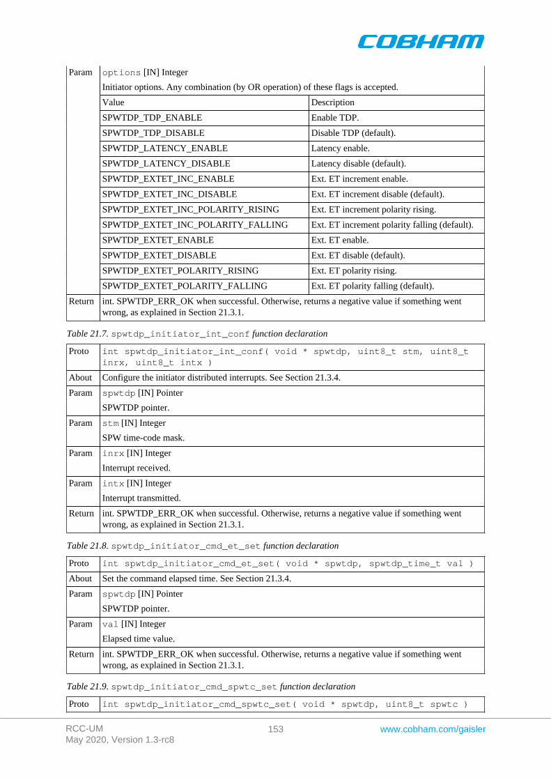
RCC-UMMay 2020, Version 1.3-rc8
153 www.cobham.com/gaisler
options [IN] Integer
Initiator options. Any combination (by OR operation) of these flags is accepted.
Value Description
SPWTDP_TDP_ENABLE Enable TDP.
SPWTDP_TDP_DISABLE Disable TDP (default).
SPWTDP_LATENCY_ENABLE Latency enable.
SPWTDP_LATENCY_DISABLE Latency disable (default).
SPWTDP_EXTET_INC_ENABLE Ext. ET increment enable.
SPWTDP_EXTET_INC_DISABLE Ext. ET increment disable (default).
SPWTDP_EXTET_INC_POLARITY_RISING Ext. ET increment polarity rising.
SPWTDP_EXTET_INC_POLARITY_FALLING Ext. ET increment polarity falling (default).
SPWTDP_EXTET_ENABLE Ext. ET enable.
SPWTDP_EXTET_DISABLE Ext. ET disable (default).
SPWTDP_EXTET_POLARITY_RISING Ext. ET polarity rising.
Param
SPWTDP_EXTET_POLARITY_FALLING Ext. ET polarity falling (default).
Return int. SPWTDP_ERR_OK when successful. Otherwise, returns a negative value if something wentwrong, as explained in Section 21.3.1.
Table 21.7. spwtdp_initiator_int_conf function declaration
Proto int spwtdp_initiator_int_conf( void * spwtdp, uint8_t stm, uint8_tinrx, uint8_t intx )
About Configure the initiator distributed interrupts. See Section 21.3.4.
spwtdp [IN] PointerParam
SPWTDP pointer.
stm [IN] IntegerParam
SPW time-code mask.
inrx [IN] IntegerParam
Interrupt received.
intx [IN] IntegerParam
Interrupt transmitted.
Return int. SPWTDP_ERR_OK when successful. Otherwise, returns a negative value if something wentwrong, as explained in Section 21.3.1.
Table 21.8. spwtdp_initiator_cmd_et_set function declaration
Proto int spwtdp_initiator_cmd_et_set( void * spwtdp, spwtdp_time_t val )
About Set the command elapsed time. See Section 21.3.4.
spwtdp [IN] PointerParam
SPWTDP pointer.
val [IN] IntegerParam
Elapsed time value.
Return int. SPWTDP_ERR_OK when successful. Otherwise, returns a negative value if something wentwrong, as explained in Section 21.3.1.
Table 21.9. spwtdp_initiator_cmd_spwtc_set function declaration
Proto int spwtdp_initiator_cmd_spwtc_set( void * spwtdp, uint8_t spwtc )
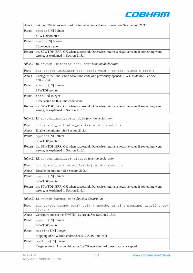
RCC-UMMay 2020, Version 1.3-rc8
154 www.cobham.com/gaisler
About Set the SPW time-code used for initialization and synchronization. See Section 21.3.4.
spwtdp [IN] PointerParam
SPWTDP pointer.
spwtc [IN] IntegerParam
Time-code value.
Return int. SPWTDP_ERR_OK when successful. Otherwise, returns a negative value if something wentwrong, as explained in Section 21.3.1.
Table 21.10. spwtdp_initiator_tstx_conf function declaration
Proto int spwtdp_initiator_tstx_conf( void * spwtdp, uint8_t tstc )
About Configure the time-stamp SPW time-code of a previously opened SPWTDP device. See Sec-tion 21.3.4.
spwtdp [IN] PointerParam
SPWTDP pointer.
tstc [IN] IntegerParam
Time stamp on this time-code value.
Return int. SPWTDP_ERR_OK when successful. Otherwise, returns a negative value if something wentwrong, as explained in Section 21.3.1.
Table 21.11. spwtdp_initiator_enable function declaration
Proto int spwtdp_initiator_enable( void * spwtdp )
About Enable the initiator. See Section 21.3.4.
spwtdp [IN] PointerParam
SPWTDP pointer.
Return int. SPWTDP_ERR_OK when successful. Otherwise, returns a negative value if something wentwrong, as explained in Section 21.3.1.
Table 21.12. spwtdp_initiator_disable function declaration
Proto int spwtdp_initiator_disable( void * spwtdp )
About Disable the initiator. See Section 21.3.4.
spwtdp [IN] PointerParam
SPWTDP pointer.
Return int. SPWTDP_ERR_OK when successful. Otherwise, returns a negative value if something wentwrong, as explained in Section 21.3.1.
Table 21.13. spwtdp_target_conf function declaration
Proto int spwtdp_target_conf( void * spwtdp, uint8_t mapping, uint32_t op-tions )
About Configure and set the SPWTDP as target. See Section 21.3.4.
spwtdp [IN] PointerParam
SPWTDP pointer.
mapping [IN] IntegerParam
Mapping of SPW time-codes versus CCSDS time-code.
options [IN] IntegerParam
Target options. Any combination (by OR operation) of these flags is accepted.
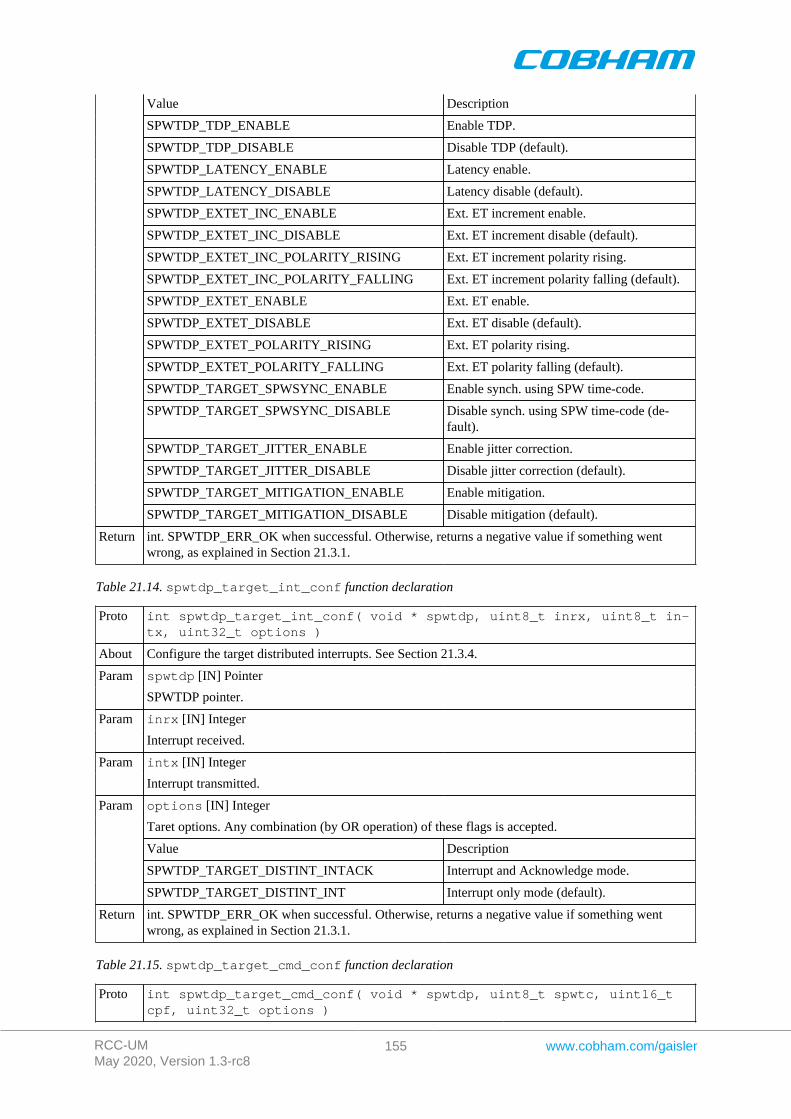
RCC-UMMay 2020, Version 1.3-rc8
155 www.cobham.com/gaisler
Value Description
SPWTDP_TDP_ENABLE Enable TDP.
SPWTDP_TDP_DISABLE Disable TDP (default).
SPWTDP_LATENCY_ENABLE Latency enable.
SPWTDP_LATENCY_DISABLE Latency disable (default).
SPWTDP_EXTET_INC_ENABLE Ext. ET increment enable.
SPWTDP_EXTET_INC_DISABLE Ext. ET increment disable (default).
SPWTDP_EXTET_INC_POLARITY_RISING Ext. ET increment polarity rising.
SPWTDP_EXTET_INC_POLARITY_FALLING Ext. ET increment polarity falling (default).
SPWTDP_EXTET_ENABLE Ext. ET enable.
SPWTDP_EXTET_DISABLE Ext. ET disable (default).
SPWTDP_EXTET_POLARITY_RISING Ext. ET polarity rising.
SPWTDP_EXTET_POLARITY_FALLING Ext. ET polarity falling (default).
SPWTDP_TARGET_SPWSYNC_ENABLE Enable synch. using SPW time-code.
SPWTDP_TARGET_SPWSYNC_DISABLE Disable synch. using SPW time-code (de-fault).
SPWTDP_TARGET_JITTER_ENABLE Enable jitter correction.
SPWTDP_TARGET_JITTER_DISABLE Disable jitter correction (default).
SPWTDP_TARGET_MITIGATION_ENABLE Enable mitigation.
SPWTDP_TARGET_MITIGATION_DISABLE Disable mitigation (default).
Return int. SPWTDP_ERR_OK when successful. Otherwise, returns a negative value if something wentwrong, as explained in Section 21.3.1.
Table 21.14. spwtdp_target_int_conf function declaration
Proto int spwtdp_target_int_conf( void * spwtdp, uint8_t inrx, uint8_t in-tx, uint32_t options )
About Configure the target distributed interrupts. See Section 21.3.4.
spwtdp [IN] PointerParam
SPWTDP pointer.
inrx [IN] IntegerParam
Interrupt received.
intx [IN] IntegerParam
Interrupt transmitted.
options [IN] Integer
Taret options. Any combination (by OR operation) of these flags is accepted.
Value Description
SPWTDP_TARGET_DISTINT_INTACK Interrupt and Acknowledge mode.
Param
SPWTDP_TARGET_DISTINT_INT Interrupt only mode (default).
Return int. SPWTDP_ERR_OK when successful. Otherwise, returns a negative value if something wentwrong, as explained in Section 21.3.1.
Table 21.15. spwtdp_target_cmd_conf function declaration
Proto int spwtdp_target_cmd_conf( void * spwtdp, uint8_t spwtc, uint16_tcpf, uint32_t options )
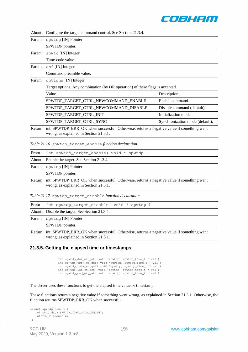
RCC-UMMay 2020, Version 1.3-rc8
156 www.cobham.com/gaisler
About Configure the target command control. See Section 21.3.4.
spwtdp [IN] PointerParam
SPWTDP pointer.
spwtc [IN] IntegerParam
Time-code value.
cpf [IN] IntegerParam
Command preamble value.
options [IN] Integer
Target options. Any combination (by OR operation) of these flags is accepted.
Value Description
SPWTDP_TARGET_CTRL_NEWCOMMAND_ENABLE Enable command.
SPWTDP_TARGET_CTRL_NEWCOMMAND_DISABLE Disable command (default).
SPWTDP_TARGET_CTRL_INIT Initialization mode.
Param
SPWTDP_TARGET_CTRL_SYNC Synchronization mode (default).
Return int. SPWTDP_ERR_OK when successful. Otherwise, returns a negative value if something wentwrong, as explained in Section 21.3.1.
Table 21.16. spwtdp_target_enable function declaration
Proto int spwtdp_target_enable( void * spwtdp )
About Enable the target. See Section 21.3.4.
spwtdp [IN] PointerParam
SPWTDP pointer.
Return int. SPWTDP_ERR_OK when successful. Otherwise, returns a negative value if something wentwrong, as explained in Section 21.3.1.
Table 21.17. spwtdp_target_disable function declaration
Proto int spwtdp_target_disable( void * spwtdp )
About Disable the target. See Section 21.3.4.
spwtdp [IN] PointerParam
SPWTDP pointer.
Return int. SPWTDP_ERR_OK when successful. Otherwise, returns a negative value if something wentwrong, as explained in Section 21.3.1.
21.3.5. Getting the elapsed time or timestamps
int spwtdp_dat_et_get( void *spwtdp, spwtdp_time_t * val ) int spwtdp_tsrx_et_get( void *spwtdp, spwtdp_time_t * val ) int spwtdp_tstx_et_get( void *spwtdp, spwtdp_time_t * val ) int spwtdp_lat_et_get( void *spwtdp, spwtdp_time_t * val ) int spwtdp_cmd_et_get( void *spwtdp, spwtdp_time_t * val )
The driver uses these functions to get the elapsed time value or timestamp.
These functions return a negative value if something went wrong, as explained in Section 21.3.1. Otherwise, thefunction returns SPWTDP_ERR_OK when successful.
struct spwtdp_time_t { uint8_t data[SPWTDP_TIME_DATA_LENGTH]; uint32_t preamble;};
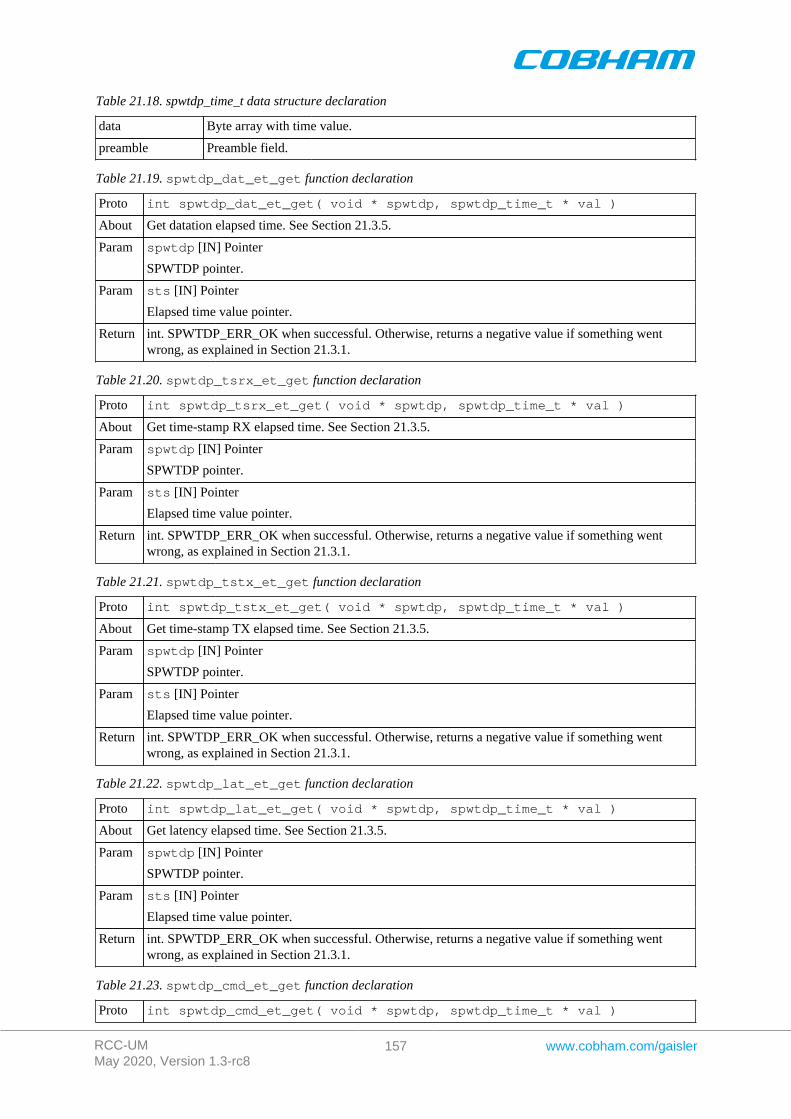
RCC-UMMay 2020, Version 1.3-rc8
157 www.cobham.com/gaisler
Table 21.18. spwtdp_time_t data structure declaration
data Byte array with time value.
preamble Preamble field.
Table 21.19. spwtdp_dat_et_get function declaration
Proto int spwtdp_dat_et_get( void * spwtdp, spwtdp_time_t * val )
About Get datation elapsed time. See Section 21.3.5.
spwtdp [IN] PointerParam
SPWTDP pointer.
sts [IN] PointerParam
Elapsed time value pointer.
Return int. SPWTDP_ERR_OK when successful. Otherwise, returns a negative value if something wentwrong, as explained in Section 21.3.1.
Table 21.20. spwtdp_tsrx_et_get function declaration
Proto int spwtdp_tsrx_et_get( void * spwtdp, spwtdp_time_t * val )
About Get time-stamp RX elapsed time. See Section 21.3.5.
spwtdp [IN] PointerParam
SPWTDP pointer.
sts [IN] PointerParam
Elapsed time value pointer.
Return int. SPWTDP_ERR_OK when successful. Otherwise, returns a negative value if something wentwrong, as explained in Section 21.3.1.
Table 21.21. spwtdp_tstx_et_get function declaration
Proto int spwtdp_tstx_et_get( void * spwtdp, spwtdp_time_t * val )
About Get time-stamp TX elapsed time. See Section 21.3.5.
spwtdp [IN] PointerParam
SPWTDP pointer.
sts [IN] PointerParam
Elapsed time value pointer.
Return int. SPWTDP_ERR_OK when successful. Otherwise, returns a negative value if something wentwrong, as explained in Section 21.3.1.
Table 21.22. spwtdp_lat_et_get function declaration
Proto int spwtdp_lat_et_get( void * spwtdp, spwtdp_time_t * val )
About Get latency elapsed time. See Section 21.3.5.
spwtdp [IN] PointerParam
SPWTDP pointer.
sts [IN] PointerParam
Elapsed time value pointer.
Return int. SPWTDP_ERR_OK when successful. Otherwise, returns a negative value if something wentwrong, as explained in Section 21.3.1.
Table 21.23. spwtdp_cmd_et_get function declaration
Proto int spwtdp_cmd_et_get( void * spwtdp, spwtdp_time_t * val )
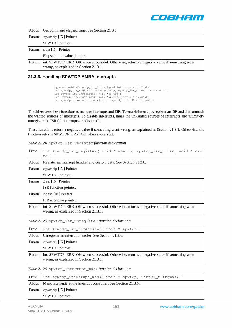
RCC-UMMay 2020, Version 1.3-rc8
158 www.cobham.com/gaisler
About Get command elapsed time. See Section 21.3.5.
spwtdp [IN] PointerParam
SPWTDP pointer.
sts [IN] PointerParam
Elapsed time value pointer.
Return int. SPWTDP_ERR_OK when successful. Otherwise, returns a negative value if something wentwrong, as explained in Section 21.3.1.
21.3.6. Handling SPWTDP AMBA interrupts
typedef void (*spwtdp_isr_t)(unsigned int ists, void *data) int spwtdp_isr_register( void *spwtdp, spwtdp_isr_t isr, void * data ) int spwtdp_isr_unregister( void *spwtdp ) int spwtdp_interrupt_mask( void *spwtdp, uint32_t irqmask ) int spwtdp_interrupt_unmask( void *spwtdp, uint32_t irqmask )
The driver uses these functions to manage interrupts and ISR. To enable interrupts, register an ISR and then unmaskthe wanted sources of interrupts. To disable interrupts, mask the unwanted sources of interrupts and ultimatelyunregister the ISR (all interrupts are disabled).
These functions return a negative value if something went wrong, as explained in Section 21.3.1. Otherwise, thefunction returns SPWTDP_ERR_OK when successful.
Table 21.24. spwtdp_isr_register function declaration
Proto int spwtdp_isr_register( void * spwtdp, spwtdp_isr_t isr, void * da-ta )
About Register an interrupt handler and custom data. See Section 21.3.6.
spwtdp [IN] PointerParam
SPWTDP pointer.
isr [IN] PointerParam
ISR function pointer.
data [IN] PointerParam
ISR user data pointer.
Return int. SPWTDP_ERR_OK when successful. Otherwise, returns a negative value if something wentwrong, as explained in Section 21.3.1.
Table 21.25. spwtdp_isr_unregister function declaration
Proto int spwtdp_isr_unregister( void * spwtdp )
About Unregister an interrupt handler. See Section 21.3.6.
spwtdp [IN] PointerParam
SPWTDP pointer.
Return int. SPWTDP_ERR_OK when successful. Otherwise, returns a negative value if something wentwrong, as explained in Section 21.3.1.
Table 21.26. spwtdp_interrupt_mask function declaration
Proto int spwtdp_interrupt_mask( void * spwtdp, uint32_t irqmask )
About Mask interrupts at the interrupt controller. See Section 21.3.6.
spwtdp [IN] PointerParam
SPWTDP pointer.
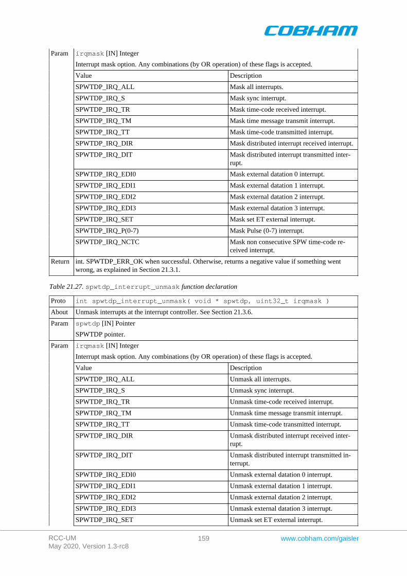
RCC-UMMay 2020, Version 1.3-rc8
159 www.cobham.com/gaisler
irqmask [IN] Integer
Interrupt mask option. Any combinations (by OR operation) of these flags is accepted.
Value Description
SPWTDP_IRQ_ALL Mask all interrupts.
SPWTDP_IRQ_S Mask sync interrupt.
SPWTDP_IRQ_TR Mask time-code received interrupt.
SPWTDP_IRQ_TM Mask time message transmit interrupt.
SPWTDP_IRQ_TT Mask time-code transmitted interrupt.
SPWTDP_IRQ_DIR Mask distributed interrupt received interrupt.
SPWTDP_IRQ_DIT Mask distributed interrupt transmitted inter-rupt.
SPWTDP_IRQ_EDI0 Mask external datation 0 interrupt.
SPWTDP_IRQ_EDI1 Mask external datation 1 interrupt.
SPWTDP_IRQ_EDI2 Mask external datation 2 interrupt.
SPWTDP_IRQ_EDI3 Mask external datation 3 interrupt.
SPWTDP_IRQ_SET Mask set ET external interrupt.
SPWTDP_IRQ_P(0-7) Mask Pulse (0-7) interrupt.
Param
SPWTDP_IRQ_NCTC Mask non consecutive SPW time-code re-ceived interrupt.
Return int. SPWTDP_ERR_OK when successful. Otherwise, returns a negative value if something wentwrong, as explained in Section 21.3.1.
Table 21.27. spwtdp_interrupt_unmask function declaration
Proto int spwtdp_interrupt_unmask( void * spwtdp, uint32_t irqmask )
About Unmask interrupts at the interrupt controller. See Section 21.3.6.
spwtdp [IN] PointerParam
SPWTDP pointer.
irqmask [IN] Integer
Interrupt mask option. Any combinations (by OR operation) of these flags is accepted.
Value Description
SPWTDP_IRQ_ALL Unmask all interrupts.
SPWTDP_IRQ_S Unmask sync interrupt.
SPWTDP_IRQ_TR Unmask time-code received interrupt.
SPWTDP_IRQ_TM Unmask time message transmit interrupt.
SPWTDP_IRQ_TT Unmask time-code transmitted interrupt.
SPWTDP_IRQ_DIR Unmask distributed interrupt received inter-rupt.
SPWTDP_IRQ_DIT Unmask distributed interrupt transmitted in-terrupt.
SPWTDP_IRQ_EDI0 Unmask external datation 0 interrupt.
SPWTDP_IRQ_EDI1 Unmask external datation 1 interrupt.
SPWTDP_IRQ_EDI2 Unmask external datation 2 interrupt.
SPWTDP_IRQ_EDI3 Unmask external datation 3 interrupt.
Param
SPWTDP_IRQ_SET Unmask set ET external interrupt.
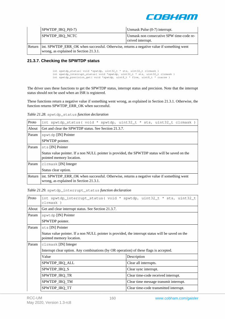
RCC-UMMay 2020, Version 1.3-rc8
160 www.cobham.com/gaisler
SPWTDP_IRQ_P(0-7) Unmask Pulse (0-7) interrupt.
SPWTDP_IRQ_NCTC Unmask non consecutive SPW time-code re-ceived interrupt.
Return int. SPWTDP_ERR_OK when successful. Otherwise, returns a negative value if something wentwrong, as explained in Section 21.3.1.
21.3.7. Checking the SPWTDP status
int spwtdp_status( void *spwtdp, uint32_t * sts, uint32_t clrmask ) int spwtdp_interrupt_status( void *spwtdp, uint32_t * sts, uint32_t clrmask ) int spwtdp_precision_get( void *spwtdp, uint8_t * fine, uint8_t * coarse )
The driver uses these functions to get the SPWTDP status, interrupt status and precision. Note that the interruptstatus should not be used when an ISR is registered.
These functions return a negative value if something went wrong, as explained in Section 21.3.1. Otherwise, thefunction returns SPWTDP_ERR_OK when successful.
Table 21.28. spwtdp_status function declaration
Proto int spwtdp_status( void * spwtdp, uint32_t * sts, uint32_t clrmask )
About Get and clear the SPWTDP status. See Section 21.3.7.
spwtdp [IN] PointerParam
SPWTDP pointer.
sts [IN] PointerParam
Status value pointer. If a non NULL pointer is provided, the SPWTDP status will be saved on thepointed memory location.
clrmask [IN] IntegerParam
Status clear option.
Return int. SPWTDP_ERR_OK when successful. Otherwise, returns a negative value if something wentwrong, as explained in Section 21.3.1.
Table 21.29. spwtdp_interrupt_status function declaration
Proto int spwtdp_interrupt_status( void * spwtdp, uint32_t * sts, uint32_tclrmask )
About Get and clear interrupt status. See Section 21.3.7.
spwtdp [IN] PointerParam
SPWTDP pointer.
sts [IN] PointerParam
Status value pointer. If a non NULL pointer is provided, the interrupt status will be saved on thepointed memory location.
clrmask [IN] Integer
Interrupt clear option. Any combinations (by OR operation) of these flags is accepted.
Value Description
SPWTDP_IRQ_ALL Clear all interrupts.
SPWTDP_IRQ_S Clear sync interrupt.
SPWTDP_IRQ_TR Clear time-code received interrupt.
SPWTDP_IRQ_TM Clear time message transmit interrupt.
Param
SPWTDP_IRQ_TT Clear time-code transmitted interrupt.
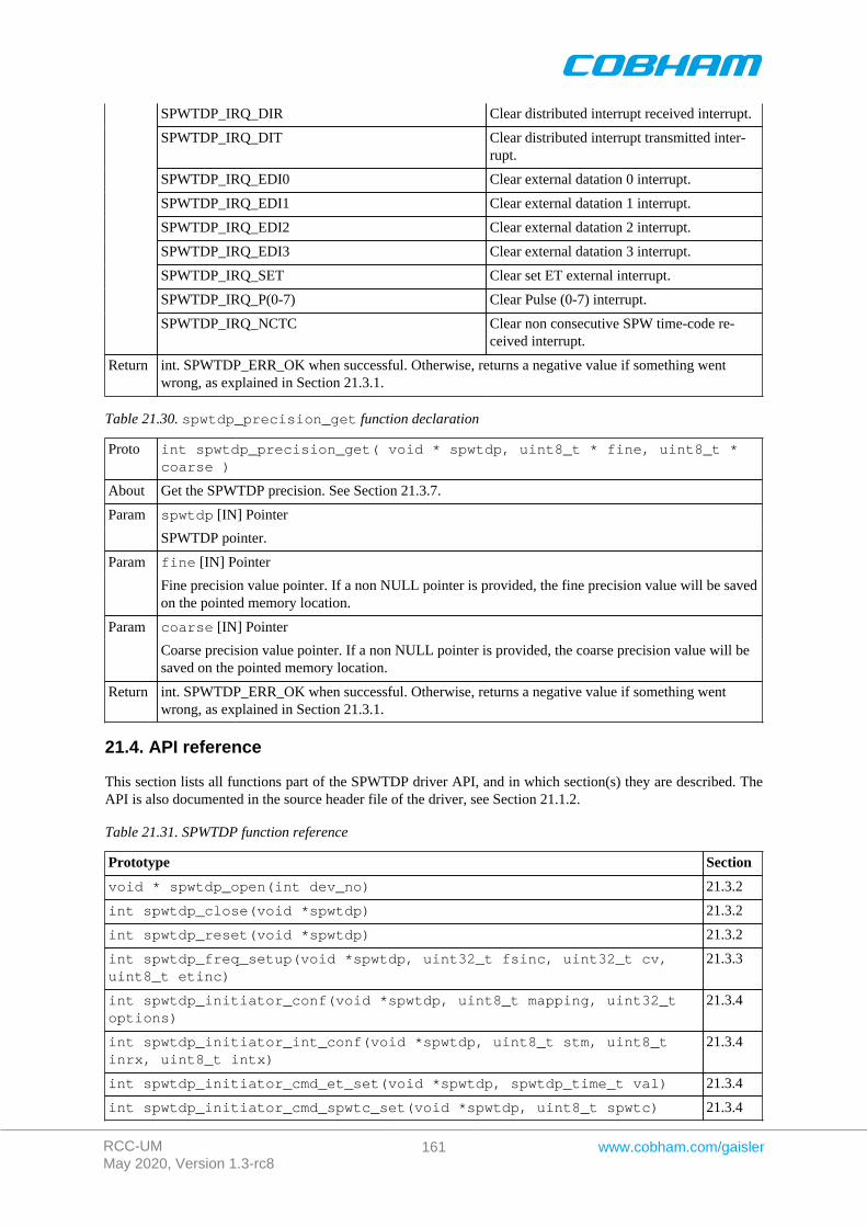
RCC-UMMay 2020, Version 1.3-rc8
161 www.cobham.com/gaisler
SPWTDP_IRQ_DIR Clear distributed interrupt received interrupt.
SPWTDP_IRQ_DIT Clear distributed interrupt transmitted inter-rupt.
SPWTDP_IRQ_EDI0 Clear external datation 0 interrupt.
SPWTDP_IRQ_EDI1 Clear external datation 1 interrupt.
SPWTDP_IRQ_EDI2 Clear external datation 2 interrupt.
SPWTDP_IRQ_EDI3 Clear external datation 3 interrupt.
SPWTDP_IRQ_SET Clear set ET external interrupt.
SPWTDP_IRQ_P(0-7) Clear Pulse (0-7) interrupt.
SPWTDP_IRQ_NCTC Clear non consecutive SPW time-code re-ceived interrupt.
Return int. SPWTDP_ERR_OK when successful. Otherwise, returns a negative value if something wentwrong, as explained in Section 21.3.1.
Table 21.30. spwtdp_precision_get function declaration
Proto int spwtdp_precision_get( void * spwtdp, uint8_t * fine, uint8_t *coarse )
About Get the SPWTDP precision. See Section 21.3.7.
spwtdp [IN] PointerParam
SPWTDP pointer.
fine [IN] PointerParam
Fine precision value pointer. If a non NULL pointer is provided, the fine precision value will be savedon the pointed memory location.
coarse [IN] PointerParam
Coarse precision value pointer. If a non NULL pointer is provided, the coarse precision value will besaved on the pointed memory location.
Return int. SPWTDP_ERR_OK when successful. Otherwise, returns a negative value if something wentwrong, as explained in Section 21.3.1.
21.4. API reference
This section lists all functions part of the SPWTDP driver API, and in which section(s) they are described. TheAPI is also documented in the source header file of the driver, see Section 21.1.2.
Table 21.31. SPWTDP function reference
Prototype Section
void * spwtdp_open(int dev_no) 21.3.2
int spwtdp_close(void *spwtdp) 21.3.2
int spwtdp_reset(void *spwtdp) 21.3.2
int spwtdp_freq_setup(void *spwtdp, uint32_t fsinc, uint32_t cv,uint8_t etinc)
21.3.3
int spwtdp_initiator_conf(void *spwtdp, uint8_t mapping, uint32_toptions)
21.3.4
int spwtdp_initiator_int_conf(void *spwtdp, uint8_t stm, uint8_tinrx, uint8_t intx)
21.3.4
int spwtdp_initiator_cmd_et_set(void *spwtdp, spwtdp_time_t val) 21.3.4
int spwtdp_initiator_cmd_spwtc_set(void *spwtdp, uint8_t spwtc) 21.3.4
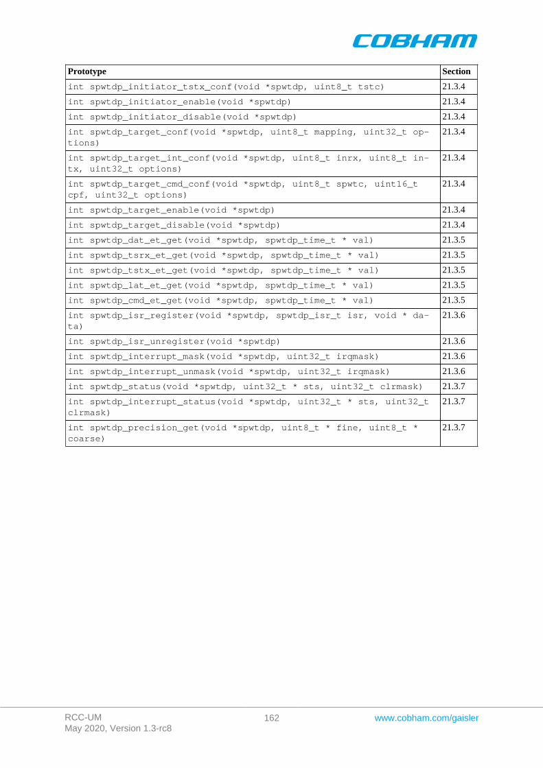
RCC-UMMay 2020, Version 1.3-rc8
162 www.cobham.com/gaisler
Prototype Section
int spwtdp_initiator_tstx_conf(void *spwtdp, uint8_t tstc) 21.3.4
int spwtdp_initiator_enable(void *spwtdp) 21.3.4
int spwtdp_initiator_disable(void *spwtdp) 21.3.4
int spwtdp_target_conf(void *spwtdp, uint8_t mapping, uint32_t op-tions)
21.3.4
int spwtdp_target_int_conf(void *spwtdp, uint8_t inrx, uint8_t in-tx, uint32_t options)
21.3.4
int spwtdp_target_cmd_conf(void *spwtdp, uint8_t spwtc, uint16_tcpf, uint32_t options)
21.3.4
int spwtdp_target_enable(void *spwtdp) 21.3.4
int spwtdp_target_disable(void *spwtdp) 21.3.4
int spwtdp_dat_et_get(void *spwtdp, spwtdp_time_t * val) 21.3.5
int spwtdp_tsrx_et_get(void *spwtdp, spwtdp_time_t * val) 21.3.5
int spwtdp_tstx_et_get(void *spwtdp, spwtdp_time_t * val) 21.3.5
int spwtdp_lat_et_get(void *spwtdp, spwtdp_time_t * val) 21.3.5
int spwtdp_cmd_et_get(void *spwtdp, spwtdp_time_t * val) 21.3.5
int spwtdp_isr_register(void *spwtdp, spwtdp_isr_t isr, void * da-ta)
21.3.6
int spwtdp_isr_unregister(void *spwtdp) 21.3.6
int spwtdp_interrupt_mask(void *spwtdp, uint32_t irqmask) 21.3.6
int spwtdp_interrupt_unmask(void *spwtdp, uint32_t irqmask) 21.3.6
int spwtdp_status(void *spwtdp, uint32_t * sts, uint32_t clrmask) 21.3.7
int spwtdp_interrupt_status(void *spwtdp, uint32_t * sts, uint32_tclrmask)
21.3.7
int spwtdp_precision_get(void *spwtdp, uint8_t * fine, uint8_t *coarse)
21.3.7
RCC-UMMay 2020, Version 1.3-rc8
163 www.cobham.com/gaisler
Chapter 22. GR1553B GRLIB MIL-STD-1553B driver
22.1. Introduction
This document describes the RTEMS 5 drivers specific to the GRLIB GR1553B core. The Remote Terminal(RT),Bus Monitor (BM and Bus Controller (BC) functionality are supported by the driver. Device discovery and re-source sharing are commonly controlled by the GR1553B driver described in this chapter. Each 1553 mode issupported by a separate driver, the drivers are documented in separate chapters.
All the GR1553B drivers relies on the RTEMS Driver Manager for the services: device detection, driver load-ing/initialization and interrupt management. Driver Manager is responsible for creating GR1553B device instancesand uniting GR1553B devices with the GR1553B low-level driver.
This section gives an brief introduction to the GRLIB GR1553B device allocation driver used internally by theBC, BM and RT device drivers. This driver controls the GR1553B device regardless of interfaces supported (BC,RT and/or BM). The device can be located at an on-chip AMBA or an AMBA-over-PCI bus. The driver providesan interface for the BC, RT and BM drivers.
Since the different interfaces (BC, BM and RT) are accessed from the same register interface on one core, theAPB device must be shared among the BC, BM and RT drivers. The GR1553B driver provides an easy functioninterface that allows the APB device to be shared safely between the BC, BM and RT device drivers.
Any combination of interface functionality is supported, but the RT and BC functionality cannot be used simul-taneously (limited by hardware).
The interface towards to the BC, BM and RT drivers is used internally by the device drivers and is not documentedhere. See respective driver for an interface description.
22.2. GR1553B Hardware
The GRLIB GR1553B core may support up to three modes depending on configuration, Bus Controller (BC),Remote Terminal (RT) or Bus Monitor (BM). The BC and RT functionality may not be used simultaneously, butthe BM may be used together with BC or RT or separately. All three modes are supported by the driver.
Interrupts generated from BC, BM and RT result in the same system interrupt, interrupts are shared.
22.3. Software driver
The driver provides an interface used internally by the BC, BM and RT device drivers, see respective driver foran interface declaration. The driver sources and definitions are listed in the table below, the path is given relativeto the RTEMS SPARC BSP source tree c/src/lib/libbsp/sparc.
Table 22.1. Source Location
Filename Description
shared/1553/gr1553b.c GR1553B Driver source
share/include/gr1553b.h GR1553B Driver interface declaration
22.4. Driver Registration
The driver must be registered to the driver manager. The registration is performed by calling thegr1553_register() function. The driver is automatically registered from the BC, BM and the RT devicedrivers registration procedure. This means that including the BC, BM and/or the RT driver will automaticallyinclude the GR1553B (this) driver.
22.5. Examples
The RCC distribution contains examples demonstrating how the GR1553B drivers are used. The examples can befound in /opt/rtems-5/src/samples/1553.
RCC-UMMay 2020, Version 1.3-rc8
164 www.cobham.com/gaisler
Chapter 23. GR1553B remote terminal driver
23.1. Introduction
This section describes the GRLIB GR1553B Remote Terminal (RT) device driver interface. The driver relies onthe GR1553B driver and the Driver Manager. The reader is assumed to be well acquainted with MIL-STD-1553and the GR1553B core.
23.1.1. GR1553B Remote Terminal Hardware
The GR1553B core supports any combination of the Bus Controller (BC), Bus Monitor (BM) and Remote Terminal(RT) functionality. This driver supports the RT functionality of the hardware, it can be used simultaneously withthe Bus Monitor (BM) functionality. When the BM is used together with the RT interrupts are shared betweenthe drivers.
The three functions (BC, BM, RT) are accessed using the same register interface, but through separate registers.In order to shared hardware resources between the three GR1553B drivers, the three depends on a lower levelGR1553B driver, see GR1553B driver section.
The driver supports the on-chip AMBA bus and the AMBA-over-PCI bus.
23.1.2. Examples
There is an example available that illustrates how the RT driver interface can be used to respond to 1553 BCcommands. The example includes code for Interrupt handling, Event Logging, Synchronize and Synchronize WithData mode codes, RX/TX data transfers and various driver configuration options. The RT will respond on subaddress 1,2 and 3, see comments in application and BC application. The RT example comes with a matching BCexample that generates BC transfers that is understood by the RT. The RT application use the Eventlog to monitorcertain transfers, the transfers are written to standard out.
The RT example includes a BM logger which can be used for debugging the 1553 bus. All 1553 transfers can belogged and sent to a Linux PC over a TCP/IP socket and saved to a raw text file for post processing. The defaultis however just to enable BM logging, for debugging one can quite easily read the raw BM log by looking at theBM registers and memory from GRMON.
In order to run all parts of the example a board with GR1553B core with BC and BM support, and a board witha GR1553B core with RT support is required.
The example is part of the Aeroflex Gaisler RTEMS distribution, it can be found under /opt/rtems-4.10/src/samples/1553/rtems-gr1553rt.c.
The example can be built by running:
$ cd /opt/rtems-4.10/src/samples/1553$ make rtems-gr1553rt
23.2. User Interface
23.2.1. Overview
The RT software driver provides access to the RT core and help with creating memory structures accessed by theRT core. The driver provides the services list below,
• Basic RT functionality (RT address, Bus and RT Status, Enabling core, etc.)• Event logging support• Interrupt support (Global Errors, Data Transfers, Mode Code Transfer)• DMA-Memory configuration• Sub Address configuration• Support for Mode Codes• Transfer Descriptor List Management per RT sub address and transfer type (RX/TX)
RCC-UMMay 2020, Version 1.3-rc8
165 www.cobham.com/gaisler
The driver sources and definitions are listed in the table below, the path is given relative to the RTEMS sourcetree c/src/lib/lbbsp/sparc.
Table 23.1. RT driver Source location
Filename Description
shared/1553/gr1553rt.c GR1553B RT Driver source
shared/include/gr1553rt.h GR1553B RT Driver interface declaration
23.2.1.1. Accessing an RT device
In order to access an RT core, a specific core must be identified (the driver support multiple devices). The coreis opened by calling gr1553rt_open(), the open function allocates an RT device by calling the lower levelGR1553B driver and initializes the RT by stopping all activity and disabling interrupts. After an RT has beenopened it can be configured gr1553rt_config(), SA-table configured, descriptor lists assigned to SA, inter-rupt callbacks registered, and finally communication started by calling gr1553rt_start(). Once the RT isstarted interrupts may be generated, data may be transferred and the event log filled. The communication can bestopped by calling gr1553rt_stop().
When the application no longer needs to access the RT core, the RT is closed by calling gr1553rt_close().
23.2.1.2. Introduction to the RT Memory areas
For the RT there are four different types of memory areas. The access to the areas is much different and involvedifferent latency requirements. The areas are:
• Sub Address (SA) Table• Buffer Descriptors (BD)• Data buffers referenced from descriptors (read or written)• Event (EV) logging buffer
The memory types are described in separate sections below. Generally three of the areas (controlled by the driver)can be dynamically allocated by the driver or assigned to a custom location by the user. Assigning a custom addressis typically useful when for example a low-latency memory is required, or the GR1553B core is located on anAMBA-over- PCI bus where memory accesses over the PCI bus will not satisfy the latency requirements by the1553 bus, instead a memory local to the RT core can be used to shorten the access time. Note that when providingcustom addresses the alignment requirement of the GR1553B core must be obeyed, which is different for differentareas and sizes. The memory areas are configured using the gr1553rt_config() function.
23.2.1.3. Sub Address Table
The RT core provides the user to program different responses per sub address and transfer type through the subaddress table (SA-table) located in memory. The RT core consult the SA-table for every 1553 data transfer com-mand on the 1553 bus. The table includes options per sub address and transfer type and a pointer to the nextdescriptor that let the user control the location of the data buffer used in the transaction. See hardware manualfor a complete description.
The SA-table is fixed size to 512 bytes.
Since the RT is required to respond to BC request within a certain time, it is vital that the RT has enough timeto lookup user configuration of a transfer, i.e. read SA-table and descriptor and possibly the data buffer as well.The driver provides a way to let the user give a custom address to the sub address table or dynamically allocateit for the user. The default action is to let the driver dynamically allocate the SA-table, the SA-table will then belocated in the main memory of the CPU. For RT core's located on an AMBA-over- PCI bus, the default action isnot acceptable due to the latency requirement mentioned above.
The SA-table can be configured per SA by calling the gr1553rt_sa_setopts() function. The mask argu-ment makes it possible to change individual bit in the SA configuration. This function must be called to enabletransfers from/to a sub address. See hardware manual for SA configuration options. Descriptor Lists are assignedto a SA by calling gr1553rt_list_sa().
RCC-UMMay 2020, Version 1.3-rc8
166 www.cobham.com/gaisler
The indication service can be used to determine the descriptor used in the next transfer, see Section 23.2.1.8.
23.2.1.4. Descriptors
A GR1553B RT descriptor is located in memory and pointed to by the SA-table. The SA-table points out thenext descriptor used for a specific sub address and transfer type. The descriptor contains three input fields: Con-trol/Status Word determines options for a specific transfer ans status of a completed transfer; Data buffer pointer,16-bit aligned; Pointer to next descriptor within sub address and transfer type, or end-of-list marker.
All descriptors are located in the same range of memory, which the driver refers to as the BD memory. TheBD memory can by dynamically allocated (located in CPU main memory) by the driver or assigned to a customlocation by the user. From the BD memory descriptors for all sub addresses are allocated by the driver. The driverworks internally with 16-bit descriptor identifiers allowing 65k descriptor in total. A descriptor is allocated for aspecific descriptor List. Each descriptor takes 32 bytes of memory.
The user can build and initialize descriptors using the API function gr1553rt_bd_init() and update thedescriptor and/or view the status and time of a completed transfer.
Descriptors are managed by a data structure named gr1553rt_list. A List is the software representation ofa chain of descriptors for a specific sub address and transfer type. Thus, 60 lists in total (two lists per SA, SA0and SA31 are for mode codes) per RT. The List simplifies the descriptor handling for the user by introducingdescriptor numbers (entry_no) used when referring to descriptors rather than the descriptor address. Up to 65kdescriptors are supported per List by the driver. A descriptor list is assigned to a SA and transfer type by callinggr1553rt_list_sa().
When a List is created and configured a maximal number of descriptors are given, giving the API a possibility toallocate the descriptors from the descriptor memory area configured.
Circular buffers can be created by a chain of descriptors where each descriptor's data buffer is one element inthe circular buffer.
23.2.1.5. Data Buffers
Data buffers are not accessed by the driver at all, the address is only written to descriptor upon user request. It isup to the user to provide the driver with valid addresses to data buffers of the required length.
Note that addresses given must be accessible by the hardware. If the RT core is located on a AMBA-over-PCI busfor example, the address of a data buffer from the RT core's point of view is most probably not the same as theaddress used by the CPU to access the buffer.
23.2.1.6. Event Logging
Transfer events (Transmission, Reception and Mode Codes) may be logged by the RT core into a memory areafor (later) processing. The events logged can be controlled by the user at a SA transfer type level and per modecode through the Mode Code Control Register.
The driver API access the eventlog on two occasions, either when the user reads the eventlog buffer using thegr1553rt_evlog_read() function or from the interrupt handler, see the interrupt section for more informa-tion. The gr1553rt_evlog_read() function is called by the user to read the eventlog, it simply copies thecurrent logged entries to a user buffer. The user must empty the driver eventlog in time to avoid entries to be over-written. A certain descriptor or SA may be logged to help the application implement communication protocols.
The eventlog is typically sized depending the frequency of the log input (logged transfers) and the frequency of thelog output (task reading the log). Every logged transfer is described with a 32-bit word, making it quite compact.
The memory of the eventlog does not require as tight latency requirement as the SA-table and descriptors. Howeverthe user still is provided the ability to put the eventlog at a custom address, or letting the driver dynamically allocateit. When providing a custom address the start address is given, the area must have room for the configured numberof entries and have the hardware required alignment.
RCC-UMMay 2020, Version 1.3-rc8
167 www.cobham.com/gaisler
Note that the alignment requirement of the eventlog varies depending on the eventlog length.
23.2.1.7. Interrupt service
The RT core can be programmed to interrupt the CPU on certain events, transfers and errors (SA-table and DMA).The driver divides transfers into two different types of events, mode codes and data transfers. The three types ofevents can be assigned custom callbacks called from the driver's interrupt service routine (ISR), and custom argu-ment can be given. The callbacks are registered per RT device using the functions gr1553rt_irq_err(),gr1553rt_irq_mc(), gr1553rt_irq_sa(). Note that the three different callbacks have different argu-ments.
Error interrupts are discovered in the ISR by looking at the IRQ event register, they are handled first. After theerror interrupt has been handled by the user (user interaction is optional) the RT core is stopped by the driver.
Data transfers and Mode Code transfers are logged in the eventlog. When a transfer-triggered interrupt occurs theISR starts processing the event log from the first event that caused the IRQ (determined by hardware register)calling the mode code or data transfer callback for each event in the log which has generated an IRQ (determined bythe IRQSR bit). Even though both the ISR and the eventlog read function r1553rt_evlog_read() processesthe eventlog, they are completely separate processes - one does not affect the other. It is up to the user to makesure that events that generated interrupt are not double processed. The callback functions are called in the sameorder as the event was generated.
Is is possible to configure different callback routines and/or arguments for different sub addresses (1..30) andtransfer types (RX/TX). Thus, 60 different callback handlers may be registered for data transfers.
23.2.1.8. Indication service
The indication service is typically used by the user to determine how many descriptors have been processed bythe hardware for a certain SA and transfer type. The gr1553rt_indication() function returns the nextdescriptor number which will be used next transfer by the RT core. The indication function takes a sub addressand an RT device as input, By remembering which descriptor was processed last the caller can determine howmany and which descriptors have been accessed by the BC.
23.2.1.9. Mode Code support
The RT core a number of registers to control and interact with mode code commands. See hardware manual whichmode codes are available. Each mode code can be disabled or enabled. Enabled mode codes can be logged andinterrupt can be generated upon transmission events. The gr1553rt_config() function is used to configurethe aforementioned mode code options. Interrupt caused by mode code transmissions can be programmed to callthe user through an callback function, see the interrupt Section 23.2.1.7.
The mode codes "Synchronization with data", "Transmit Bit word" and "Transmit Vector word" can be interactedwith through a register interface. The register interface can be read with the gr1553rt_status() functionand selected (or all) bits of the bit word and vector word can be written using gr1553rt_set_vecword()function.
Other mode codes can interacted with using the Bus Status Register of the RT core. The registercan be read using the gr1553rt_status() function and written selectable bit can be written usinggr1553rt_set_bussts().
23.2.1.10. RT Time
The RT core has an internal time counter with a configurable time resolution. The finest time resolution of thetimer counter is one microsecond. The resolution is configured using the gr1553rt_config() function. Thecurrent time is read by calling the gr1553rt_status() function.
23.2.2. Application Programming Interface
The RT driver API consists of the functions in the table below.
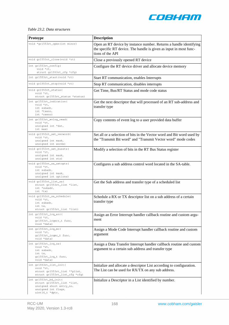
RCC-UMMay 2020, Version 1.3-rc8
168 www.cobham.com/gaisler
Table 23.2. Data structures
Protoype Descriptionvoid *gr1553rt_open(int minor) Open an RT device by instance number. Returns a handle identifying
the specific RT device. The handle is given as input in most func-tions of the API
void gr1553rt_close(void *rt) Close a previously opened RT device
int gr1553rt_config( void *rt, struct gr1553rt_cfg *cfg)
Configure the RT device driver and allocate device memory
int gr1553rt_start(void *rt) Start RT communication, enables Interrupts
void gr1553rt_stop(void *rt) Stop RT communication, disables interrupts
void gr1553rt_status( void *rt, struct gr1553rt_status *status)
Get Time, Bus/RT Status and mode code status
int gr1553rt_indication( void *rt, int subadr, int *txeno, int *rxeno)
Get the next descriptor that will processed of an RT sub-address andtransfer type
int gr1553rt_evlog_read( void *rt, unsigned int *dst, int max)
Copy contents of event log to a user provided data buffer
void gr1553rt_set_vecword( void *rt, unsigned int mask, unsigned int words)
Set all or a selection of bits in the Vector word and Bit word used bythe "Transmit Bit word" and "Transmit Vector word" mode codes
void gr1553rt_set_bussts( void *rt, unsigned int mask, unsigned int sts)
Modify a selection of bits in the RT Bus Status register
void gr1553rt_sa_setopts( void *rt, int subadr, unsigned int mask, unsigned int options)
Configures a sub address control word located in the SA-table.
void gr1553rt_list_sa( struct gr1553rt_list *list, int *subadr, int *tx)
Get the Sub address and transfer type of a scheduled list
void gr1553rt_sa_schedule( void *rt, int subadr, int tx, struct gr1553rt_list *list)
Schedule a RX or TX descriptor list on a sub address of a certaintransfer type
int gr1553rt_irq_err( void *rt, gr1553rt_irqerr_t func, void *data)
Assign an Error Interrupt handler callback routine and custom argu-ment
int gr1553rt_irq_mc( void *rt, gr1553rt_irqmc_t func, void *data)
Assign a Mode Code Interrupt handler callback routine and customargument
int gr1553rt_irq_sa( void *rt, int subadr, int tx, gr1553rt_irq_t func, void *data)
Assign a Data Transfer Interrupt handler callback routine and customargument to a certain sub address and transfer type
int gr1553rt_list_init( void *rt, struct gr1553rt_list **plist, struct gr1553rt_list_cfg *cfg)
Initialize and allocate a descriptor List according to configuration.The List can be used for RX/TX on any sub address.
int gr1553rt_bd_init( struct gr1553rt_list *list, unsigned short entry_no, unsigned int flags, uint16_t *dptr,
Initialize a Descriptor in a List identified by number.
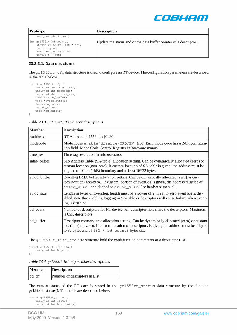
RCC-UMMay 2020, Version 1.3-rc8
169 www.cobham.com/gaisler
Protoype Description unsigned short next)
int gr1553rt_bd_update( struct gr1553rt_list *list, int entry_no, unsigned int *status, uint16_t **dptr)
Update the status and/or the data buffer pointer of a descriptor.
23.2.2.1. Data structures
The gr1553rt_cfg data structure is used to configure an RT device. The configuration parameters are describedin the table below.
struct gr1553rt_cfg { unsigned char rtaddress; unsigned int modecode; unsigned short time_res; void *satab_buffer; void *evlog_buffer; int evlog_size; int bd_count; void *bd_buffer;};
Table 23.3. gr1553rt_cfg member descriptions
Member Description
rtaddress RT Address on 1553 bus [0..30]
modecode Mode codes enable/disable/IRQ/EV-Log. Each mode code has a 2-bit configura-tion field. Mode Code Control Register in hardware manual
time_res Time tag resolution in microseconds
satab_buffer Sub Address Table (SA-table) allocation setting. Can be dynamically allocated (zero) orcustom location (non-zero). If custom location of SA-table is given, the address must bealigned to 10-bit (1kB) boundary and at least 16*32 bytes.
evlog_buffer Eventlog DMA buffer allocation setting. Can be dynamically allocated (zero) or cus-tom location (non-zero). If custom location of eventlog is given, the address must be ofevlog_size and aligned to evlog_size. See hardware manual.
evlog_size Length in bytes of Eventlog, length must be a power of 2. If set to zero event log is dis-abled, note that enabling logging in SA-table or descriptors will cause failure when event-log is disabled.
bd_count Number of descriptors for RT device. All descriptor lists share the descriptors. Maximumis 65K descriptors.
bd_buffer Descriptor memory area allocation setting. Can be dynamically allocated (zero) or customlocation (non-zero). If custom location of descriptors is given, the address must be alignedto 32 bytes and of (32 * bd_count) bytes size.
The gr1553rt_list_cfg data structure hold the configuration parameters of a descriptor List.
struct gr1553rt_list_cfg { unsigned int bd_cnt;};
Table 23.4. gr1553rt_list_cfg member descriptions
Member Description
bd_cnt Number of descriptors in List
The current status of the RT core is stored in the gr1553rt_status data structure by the functiongr1553rt_status(). The fields are described below.
struct gr1553rt_status { unsigned int status; unsigned int bus_status;
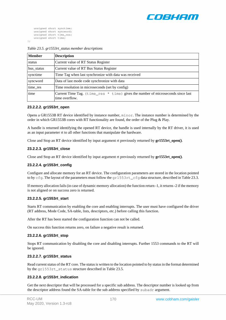
RCC-UMMay 2020, Version 1.3-rc8
170 www.cobham.com/gaisler
unsigned short synctime; unsigned short syncword; unsigned short time_res; unsigned short time;};
Table 23.5. gr1553rt_status member descriptions
Member Description
status Current value of RT Status Register
bus_status Current value of RT Bus Status Register
synctime Time Tag when last synchronize with data was received
syncword Data of last mode code synchronize with data
time_res Time resolution in microseconds (set by config)
time Current Time Tag. (time_res * time) gives the number of microseconds since lasttime overflow.
23.2.2.2. gr1553rt_open
Opens a GR1553B RT device identified by instance number, minor. The instance number is determined by theorder in which GR1553B cores with RT functionality are found, the order of the Plug & Play.
A handle is returned identifying the opened RT device, the handle is used internally by the RT driver, it is usedas an input parameter rt to all other functions that manipulate the hardware.
Close and Stop an RT device identified by input argument rt previously returned by gr1553rt_open().
23.2.2.3. gr1553rt_close
Close and Stop an RT device identified by input argument rt previously returned by gr1553rt_open().
23.2.2.4. gr1553rt_config
Configure and allocate memory for an RT device. The configuration parameters are stored in the location pointedto by cfg. The layout of the parameters must follow the gr1553rt_cfg data structure, described in Table 23.3.
If memory allocation fails (in case of dynamic memory allocation) the function return -1, it returns -2 if the memoryis not aligned or on success zero is returned.
23.2.2.5. gr1553rt_start
Starts RT communication by enabling the core and enabling interrupts. The user must have configured the driver(RT address, Mode Code, SA-table, lists, descriptors, etc.) before calling this function.
After the RT has been started the configuration function can not be called.
On success this function returns zero, on failure a negative result is returned.
23.2.2.6. gr1553rt_stop
Stops RT communication by disabling the core and disabling interrupts. Further 1553 commands to the RT willbe ignored.
23.2.2.7. gr1553rt_status
Read current status of the RT core. The status is written to the location pointed to by status in the format determinedby the gr1553rt_status structure described in Table 23.5.
23.2.2.8. gr1553rt_indication
Get the next descriptor that will be processed for a specific sub address. The descriptor number is looked up fromthe descriptor address found the SA-table for the sub address specified by subadr argument.
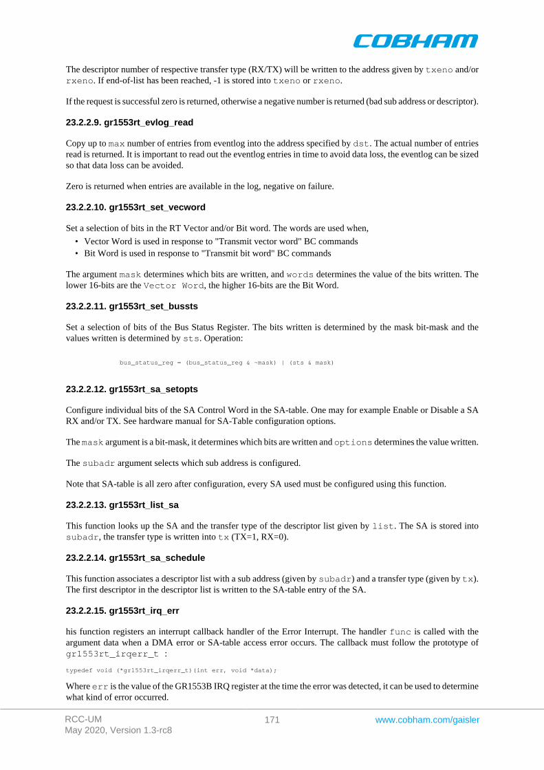
RCC-UMMay 2020, Version 1.3-rc8
171 www.cobham.com/gaisler
The descriptor number of respective transfer type (RX/TX) will be written to the address given by txeno and/orrxeno. If end-of-list has been reached, -1 is stored into txeno or rxeno.
If the request is successful zero is returned, otherwise a negative number is returned (bad sub address or descriptor).
23.2.2.9. gr1553rt_evlog_read
Copy up to max number of entries from eventlog into the address specified by dst. The actual number of entriesread is returned. It is important to read out the eventlog entries in time to avoid data loss, the eventlog can be sizedso that data loss can be avoided.
Zero is returned when entries are available in the log, negative on failure.
23.2.2.10. gr1553rt_set_vecword
Set a selection of bits in the RT Vector and/or Bit word. The words are used when,
• Vector Word is used in response to "Transmit vector word" BC commands• Bit Word is used in response to "Transmit bit word" BC commands
The argument mask determines which bits are written, and words determines the value of the bits written. Thelower 16-bits are the Vector Word, the higher 16-bits are the Bit Word.
23.2.2.11. gr1553rt_set_bussts
Set a selection of bits of the Bus Status Register. The bits written is determined by the mask bit-mask and thevalues written is determined by sts. Operation:
bus_status_reg = (bus_status_reg & ~mask) | (sts & mask)
23.2.2.12. gr1553rt_sa_setopts
Configure individual bits of the SA Control Word in the SA-table. One may for example Enable or Disable a SARX and/or TX. See hardware manual for SA-Table configuration options.
The mask argument is a bit-mask, it determines which bits are written and options determines the value written.
The subadr argument selects which sub address is configured.
Note that SA-table is all zero after configuration, every SA used must be configured using this function.
23.2.2.13. gr1553rt_list_sa
This function looks up the SA and the transfer type of the descriptor list given by list. The SA is stored intosubadr, the transfer type is written into tx (TX=1, RX=0).
23.2.2.14. gr1553rt_sa_schedule
This function associates a descriptor list with a sub address (given by subadr) and a transfer type (given by tx).The first descriptor in the descriptor list is written to the SA-table entry of the SA.
23.2.2.15. gr1553rt_irq_err
his function registers an interrupt callback handler of the Error Interrupt. The handler func is called with theargument data when a DMA error or SA-table access error occurs. The callback must follow the prototype ofgr1553rt_irqerr_t :
typedef void (*gr1553rt_irqerr_t)(int err, void *data);
Where err is the value of the GR1553B IRQ register at the time the error was detected, it can be used to determinewhat kind of error occurred.
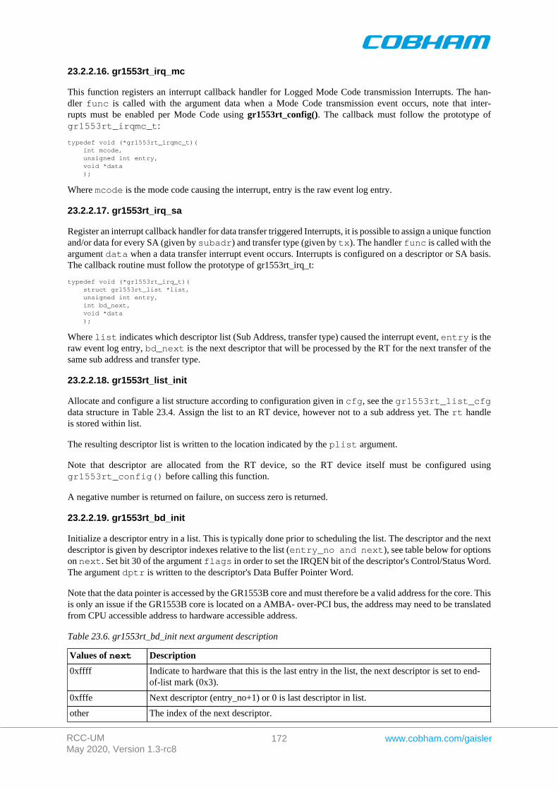
RCC-UMMay 2020, Version 1.3-rc8
172 www.cobham.com/gaisler
23.2.2.16. gr1553rt_irq_mc
This function registers an interrupt callback handler for Logged Mode Code transmission Interrupts. The han-dler func is called with the argument data when a Mode Code transmission event occurs, note that inter-rupts must be enabled per Mode Code using gr1553rt_config(). The callback must follow the prototype ofgr1553rt_irqmc_t:
typedef void (*gr1553rt_irqmc_t)( int mcode, unsigned int entry, void *data );
Where mcode is the mode code causing the interrupt, entry is the raw event log entry.
23.2.2.17. gr1553rt_irq_sa
Register an interrupt callback handler for data transfer triggered Interrupts, it is possible to assign a unique functionand/or data for every SA (given by subadr) and transfer type (given by tx). The handler func is called with theargument data when a data transfer interrupt event occurs. Interrupts is configured on a descriptor or SA basis.The callback routine must follow the prototype of gr1553rt_irq_t:
typedef void (*gr1553rt_irq_t)( struct gr1553rt_list *list, unsigned int entry, int bd_next, void *data );
Where list indicates which descriptor list (Sub Address, transfer type) caused the interrupt event, entry is theraw event log entry, bd_next is the next descriptor that will be processed by the RT for the next transfer of thesame sub address and transfer type.
23.2.2.18. gr1553rt_list_init
Allocate and configure a list structure according to configuration given in cfg, see the gr1553rt_list_cfgdata structure in Table 23.4. Assign the list to an RT device, however not to a sub address yet. The rt handleis stored within list.
The resulting descriptor list is written to the location indicated by the plist argument.
Note that descriptor are allocated from the RT device, so the RT device itself must be configured usinggr1553rt_config() before calling this function.
A negative number is returned on failure, on success zero is returned.
23.2.2.19. gr1553rt_bd_init
Initialize a descriptor entry in a list. This is typically done prior to scheduling the list. The descriptor and the nextdescriptor is given by descriptor indexes relative to the list (entry_no and next), see table below for optionson next. Set bit 30 of the argument flags in order to set the IRQEN bit of the descriptor's Control/Status Word.The argument dptr is written to the descriptor's Data Buffer Pointer Word.
Note that the data pointer is accessed by the GR1553B core and must therefore be a valid address for the core. Thisis only an issue if the GR1553B core is located on a AMBA- over-PCI bus, the address may need to be translatedfrom CPU accessible address to hardware accessible address.
Table 23.6. gr1553rt_bd_init next argument description
Values of next Description
0xffff Indicate to hardware that this is the last entry in the list, the next descriptor is set to end-of-list mark (0x3).
0xfffe Next descriptor (entry_no+1) or 0 is last descriptor in list.
other The index of the next descriptor.

RCC-UMMay 2020, Version 1.3-rc8
173 www.cobham.com/gaisler
A negative number is returned on failure, on success a zero is returned.
23.2.2.20. gr1553rt_bd_update
Manipulate and read the Control/Status and Data Pointer words of a descriptor.
If status is non-zero, the Control/Status word is swapped with the content pointed to by status.
If dptr is non-zero, the Data Pointer word is swapped with the content pointed to by dptr.
A negative number is returned on failure, on success a zero is returned.
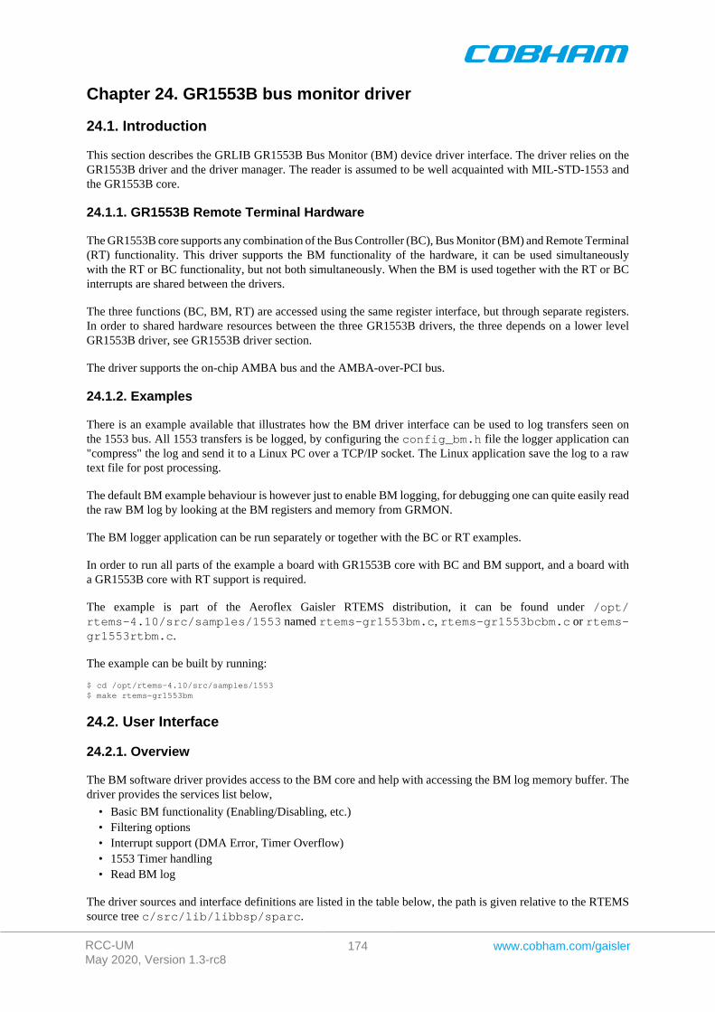
RCC-UMMay 2020, Version 1.3-rc8
174 www.cobham.com/gaisler
Chapter 24. GR1553B bus monitor driver
24.1. Introduction
This section describes the GRLIB GR1553B Bus Monitor (BM) device driver interface. The driver relies on theGR1553B driver and the driver manager. The reader is assumed to be well acquainted with MIL-STD-1553 andthe GR1553B core.
24.1.1. GR1553B Remote Terminal Hardware
The GR1553B core supports any combination of the Bus Controller (BC), Bus Monitor (BM) and Remote Terminal(RT) functionality. This driver supports the BM functionality of the hardware, it can be used simultaneouslywith the RT or BC functionality, but not both simultaneously. When the BM is used together with the RT or BCinterrupts are shared between the drivers.
The three functions (BC, BM, RT) are accessed using the same register interface, but through separate registers.In order to shared hardware resources between the three GR1553B drivers, the three depends on a lower levelGR1553B driver, see GR1553B driver section.
The driver supports the on-chip AMBA bus and the AMBA-over-PCI bus.
24.1.2. Examples
There is an example available that illustrates how the BM driver interface can be used to log transfers seen onthe 1553 bus. All 1553 transfers is be logged, by configuring the config_bm.h file the logger application can"compress" the log and send it to a Linux PC over a TCP/IP socket. The Linux application save the log to a rawtext file for post processing.
The default BM example behaviour is however just to enable BM logging, for debugging one can quite easily readthe raw BM log by looking at the BM registers and memory from GRMON.
The BM logger application can be run separately or together with the BC or RT examples.
In order to run all parts of the example a board with GR1553B core with BC and BM support, and a board witha GR1553B core with RT support is required.
The example is part of the Aeroflex Gaisler RTEMS distribution, it can be found under /opt/rtems-4.10/src/samples/1553 named rtems-gr1553bm.c, rtems-gr1553bcbm.c or rtems-gr1553rtbm.c.
The example can be built by running:
$ cd /opt/rtems-4.10/src/samples/1553$ make rtems-gr1553bm
24.2. User Interface
24.2.1. Overview
The BM software driver provides access to the BM core and help with accessing the BM log memory buffer. Thedriver provides the services list below,
• Basic BM functionality (Enabling/Disabling, etc.)• Filtering options• Interrupt support (DMA Error, Timer Overflow)• 1553 Timer handling• Read BM log
The driver sources and interface definitions are listed in the table below, the path is given relative to the RTEMSsource tree c/src/lib/libbsp/sparc.
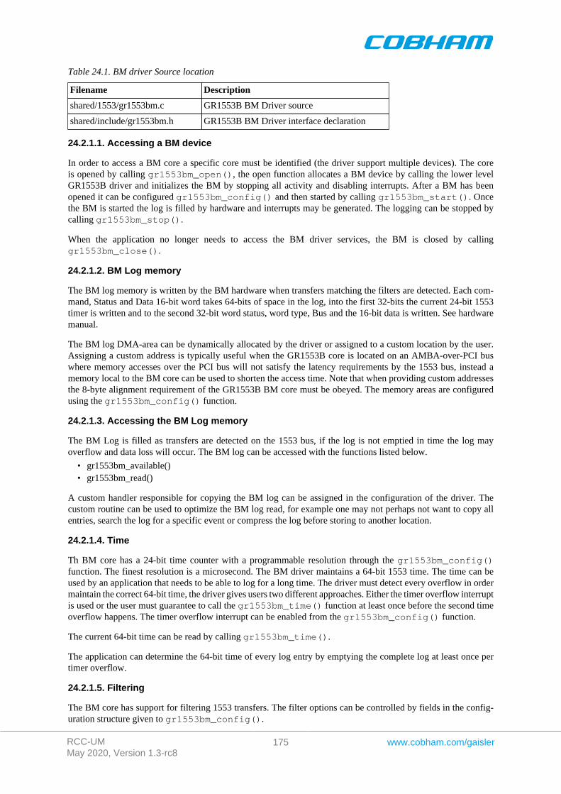
RCC-UMMay 2020, Version 1.3-rc8
175 www.cobham.com/gaisler
Table 24.1. BM driver Source location
Filename Description
shared/1553/gr1553bm.c GR1553B BM Driver source
shared/include/gr1553bm.h GR1553B BM Driver interface declaration
24.2.1.1. Accessing a BM device
In order to access a BM core a specific core must be identified (the driver support multiple devices). The coreis opened by calling gr1553bm_open(), the open function allocates a BM device by calling the lower levelGR1553B driver and initializes the BM by stopping all activity and disabling interrupts. After a BM has beenopened it can be configured gr1553bm_config() and then started by calling gr1553bm_start(). Oncethe BM is started the log is filled by hardware and interrupts may be generated. The logging can be stopped bycalling gr1553bm_stop().
When the application no longer needs to access the BM driver services, the BM is closed by callinggr1553bm_close().
24.2.1.2. BM Log memory
The BM log memory is written by the BM hardware when transfers matching the filters are detected. Each com-mand, Status and Data 16-bit word takes 64-bits of space in the log, into the first 32-bits the current 24-bit 1553timer is written and to the second 32-bit word status, word type, Bus and the 16-bit data is written. See hardwaremanual.
The BM log DMA-area can be dynamically allocated by the driver or assigned to a custom location by the user.Assigning a custom address is typically useful when the GR1553B core is located on an AMBA-over-PCI buswhere memory accesses over the PCI bus will not satisfy the latency requirements by the 1553 bus, instead amemory local to the BM core can be used to shorten the access time. Note that when providing custom addressesthe 8-byte alignment requirement of the GR1553B BM core must be obeyed. The memory areas are configuredusing the gr1553bm_config() function.
24.2.1.3. Accessing the BM Log memory
The BM Log is filled as transfers are detected on the 1553 bus, if the log is not emptied in time the log mayoverflow and data loss will occur. The BM log can be accessed with the functions listed below.
• gr1553bm_available()• gr1553bm_read()
A custom handler responsible for copying the BM log can be assigned in the configuration of the driver. Thecustom routine can be used to optimize the BM log read, for example one may not perhaps not want to copy allentries, search the log for a specific event or compress the log before storing to another location.
24.2.1.4. Time
Th BM core has a 24-bit time counter with a programmable resolution through the gr1553bm_config()function. The finest resolution is a microsecond. The BM driver maintains a 64-bit 1553 time. The time can beused by an application that needs to be able to log for a long time. The driver must detect every overflow in ordermaintain the correct 64-bit time, the driver gives users two different approaches. Either the timer overflow interruptis used or the user must guarantee to call the gr1553bm_time() function at least once before the second timeoverflow happens. The timer overflow interrupt can be enabled from the gr1553bm_config() function.
The current 64-bit time can be read by calling gr1553bm_time().
The application can determine the 64-bit time of every log entry by emptying the complete log at least once pertimer overflow.
24.2.1.5. Filtering
The BM core has support for filtering 1553 transfers. The filter options can be controlled by fields in the config-uration structure given to gr1553bm_config().
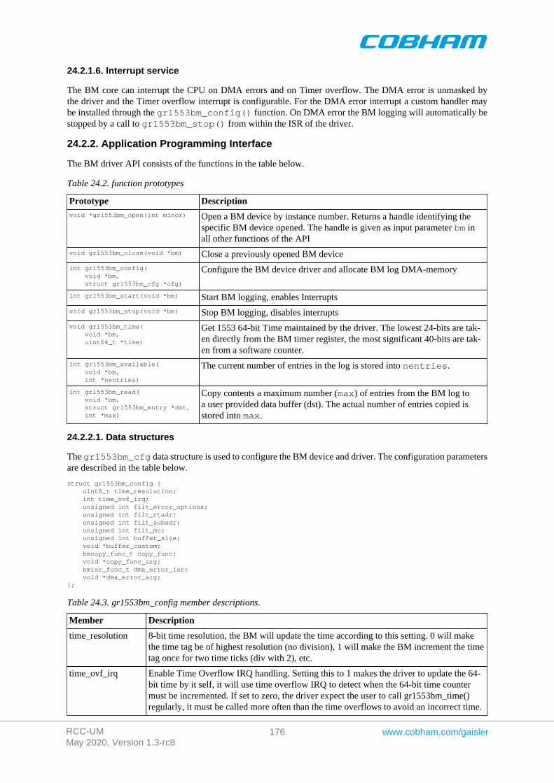
RCC-UMMay 2020, Version 1.3-rc8
176 www.cobham.com/gaisler
24.2.1.6. Interrupt service
The BM core can interrupt the CPU on DMA errors and on Timer overflow. The DMA error is unmasked bythe driver and the Timer overflow interrupt is configurable. For the DMA error interrupt a custom handler maybe installed through the gr1553bm_config() function. On DMA error the BM logging will automatically bestopped by a call to gr1553bm_stop() from within the ISR of the driver.
24.2.2. Application Programming Interface
The BM driver API consists of the functions in the table below.
Table 24.2. function prototypes
Prototype Descriptionvoid *gr1553bm_open(int minor) Open a BM device by instance number. Returns a handle identifying the
specific BM device opened. The handle is given as input parameter bm inall other functions of the API
void gr1553bm_close(void *bm) Close a previously opened BM device
int gr1553bm_config( void *bm, struct gr1553bm_cfg *cfg)
Configure the BM device driver and allocate BM log DMA-memory
int gr1553bm_start(void *bm) Start BM logging, enables Interrupts
void gr1553bm_stop(void *bm) Stop BM logging, disables interrupts
void gr1553bm_time( void *bm, uint64_t *time)
Get 1553 64-bit Time maintained by the driver. The lowest 24-bits are tak-en directly from the BM timer register, the most significant 40-bits are tak-en from a software counter.
int gr1553bm_available( void *bm, int *nentries)
The current number of entries in the log is stored into nentries.
int gr1553bm_read( void *bm, struct gr1553bm_entry *dst, int *max)
Copy contents a maximum number (max) of entries from the BM log toa user provided data buffer (dst). The actual number of entries copied isstored into max.
24.2.2.1. Data structures
The gr1553bm_cfg data structure is used to configure the BM device and driver. The configuration parametersare described in the table below.
struct gr1553bm_config { uint8_t time_resolution; int time_ovf_irq; unsigned int filt_error_options; unsigned int filt_rtadr; unsigned int filt_subadr; unsigned int filt_mc; unsigned int buffer_size; void *buffer_custom; bmcopy_func_t copy_func; void *copy_func_arg; bmisr_func_t dma_error_isr; void *dma_error_arg;};
Table 24.3. gr1553bm_config member descriptions.
Member Description
time_resolution 8-bit time resolution, the BM will update the time according to this setting. 0 will makethe time tag be of highest resolution (no division), 1 will make the BM increment the timetag once for two time ticks (div with 2), etc.
time_ovf_irq Enable Time Overflow IRQ handling. Setting this to 1 makes the driver to update the 64-bit time by it self, it will use time overflow IRQ to detect when the 64-bit time countermust be incremented. If set to zero, the driver expect the user to call gr1553bm_time()regularly, it must be called more often than the time overflows to avoid an incorrect time.
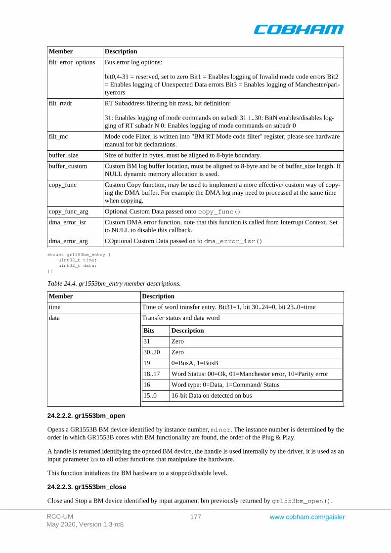
RCC-UMMay 2020, Version 1.3-rc8
177 www.cobham.com/gaisler
Member Description
filt_error_options Bus error log options:
bit0,4-31 = reserved, set to zero Bit1 = Enables logging of Invalid mode code errors Bit2= Enables logging of Unexpected Data errors Bit3 = Enables logging of Manchester/pari-tyerrors
filt_rtadr RT Subaddress filtering bit mask, bit definition:
31: Enables logging of mode commands on subadr 31 1..30: BitN enables/disables log-ging of RT subadr N 0: Enables logging of mode commands on subadr 0
filt_mc Mode code Filter, is written into "BM RT Mode code filter" register, please see hardwaremanual for bit declarations.
buffer_size Size of buffer in bytes, must be aligned to 8-byte boundary.
buffer_custom Custom BM log buffer location, must be aligned to 8-byte and be of buffer_size length. IfNULL dynamic memory allocation is used.
copy_func Custom Copy function, may be used to implement a more effective/ custom way of copy-ing the DMA buffer. For example the DMA log may need to processed at the same timewhen copying.
copy_func_arg Optional Custom Data passed onto copy_func()
dma_error_isr Custom DMA error function, note that this function is called from Interrupt Context. Setto NULL to disable this callback.
dma_error_arg COptional Custom Data passed on to dma_error_isr()
struct gr1553bm_entry { uint32_t time; uint32_t data;};
Table 24.4. gr1553bm_entry member descriptions.
Member Description
time Time of word transfer entry. Bit31=1, bit 30..24=0, bit 23..0=time
data Transfer status and data word
Bits Description
31 Zero
30..20 Zero
19 0=BusA, 1=BusB
18..17 Word Status: 00=Ok, 01=Manchester error, 10=Parity error
16 Word type: 0=Data, 1=Command/ Status
15..0 16-bit Data on detected on bus
24.2.2.2. gr1553bm_open
Opens a GR1553B BM device identified by instance number, minor. The instance number is determined by theorder in which GR1553B cores with BM functionality are found, the order of the Plug & Play.
A handle is returned identifying the opened BM device, the handle is used internally by the driver, it is used as aninput parameter bm to all other functions that manipulate the hardware.
This function initializes the BM hardware to a stopped/disable level.
24.2.2.3. gr1553bm_close
Close and Stop a BM device identified by input argument bm previously returned by gr1553bm_open().
RCC-UMMay 2020, Version 1.3-rc8
178 www.cobham.com/gaisler
24.2.2.4. gr1553bm_config
Configure and allocate the log DMA-memory for a BM device. The configuration parameters are stored in thelocation pointed to by cfg. The layout of the parameters must follow the gr1553bm_config data structure,described in Table 24.3.
If BM device is started or memory allocation fails (in case of dynamic memory allocation) the function returns -1,it returns -2 if the memory is not aligned or on success zero is returned.
24.2.2.5. gr1553bm_start
Starts 1553 logging by enabling the core and enabling interrupts. The user must have configured the driver (logbuffer, timer, filtering, etc.) before calling this function.
After the BM has been started the configuration function can not be called.
On success this function returns zero, on failure a negative result is returned.
24.2.2.6. gr1553bm_stop
Stops 1553 logging by disabling the core and disabling interrupts. Further 1553 transfers will be ignored.
24.2.2.7. gr1553bm_time
This function reads the driver's internal 64-bit 1553 Time. The low 24-bit time is acquired from BM hardware,the MSB is taken from a software counter internal to the driver. The counter is incremented every time the Timeoverflows by:
• using "Time overflow" IRQ if enabled in user configuration• by checking "Time overflow" IRQ flag (IRQ is disabled), it is required that user calls this function before
the next timer overflow. The software can not distinguish between one or two timer overflows. This functionwill check the overflow flag and increment the driver internal time if overflow has occurred since last call.
This function update software time counters and store the current time into the address indicated by the argumenttime.
24.2.2.8. gr1553bm_available
Copy up to max number of entries from BM log into the address specified by dst. The actual number of entriesread is returned in the location of max (zero when no entries available). The max argument is thus in/out. It isimportant to read out the log entries in time to avoid data loss, the log can be sized so that data loss can be avoided.
Zero is returned on success, on failure a negative number is returned.
24.2.2.9. gr1553bm_read
Copy up to max number of entries from BM log into the address specified by dst. The actual number of entriesread is returned in the location of max (zero when no entries available). The max argument is thus in/out. It isimportant to read out the log entries in time to avoid data loss, the log can be sized so that data loss can be avoided.
Zero is returned on success, on failure a negative number is returned.

RCC-UMMay 2020, Version 1.3-rc8
179 www.cobham.com/gaisler
Chapter 25. GR1553B bus controller driver
25.1. Introduction
This section describes the GRLIB GR1553B Bus Controller (BC) device driver interface. The driver relies on theGR1553B driver and the driver manager. The reader is assumed to be well acquainted with MIL-STD-1553 andthe GR1553B core.
25.1.1. GR1553B Bus Controller Hardware
The GR1553B core supports any combination of the Bus Controller (BC), Bus Monitor (BM) and Remote Terminal(RT) functionality. This driver supports the BC functionality of the hardware, it can be used simultaneously withthe Bus Monitor (BM) functionality. When the BM is used together with the BC, interrupts are shared betweenthe drivers.
The three functions (BC, BM, RT) are accessed using the same register interface, but through separate registers.In order to share hardware resources between the three GR1553B drivers, the three depends on a lower levelGR1553B driver, see Chapter 22.
The driver supports the on-chip AMBA bus and the AMBA-over-PCI bus.
25.1.2. Software driver
The BC driver is split in two parts, one where the driver access the hardware device and one part where thedescriptors are managed. The two parts are described in two separate sections below.
Transfer and conditional descriptors are collected into a descriptor list. A descriptor list consists of a set of MajorFrames, which consist of a set of Minor Frames which in turn consists of up to 32 descriptors (also called Slots).The composition of Major/Minor Frames and slots is configured by the user, and is highly dependent of application.
The Major/Minor/Slot construction can be seen as a tree, the tree does not have to be symmetrically, i.e. Majorframes may contain different numbers of Minor Frames and Minor Frames may contain different numbers of Slot.
GR1553B BC descriptor lists are generated by the list API available in gr1553bc_list.h.
The driver provides the following services:
• Start, Stop, Pause and Resume descriptor list execution• Synchronous and asynchronous descriptor list management• Interrupt handling• BC status• Major/Minor Frame and Slot (descriptor) model of communication• Current Descriptor (Major/Minor/Slot) Execution Indication• Software External Trigger generation, used mainly for debugging or custom time synchronization• Major/Minor Frame and Slot/Message ID• Minor Frame time slot management
The driver sources and definitions are listed in the table below, the path is given relative to the RTEMS SPARCBSP source tree c/src/lib/libbsp/sparc.
Table 25.1. BC driver Source location
Filename Description
shared/1553/gr1553bc.c GR1553B BC Driver source
shared/1553/gr1553bc_list.c GR1553B BC List handling source
shared/include/gr1553bc.h GR1553B BC Driver interface declaration
shared/include/gr1553bc_list.h GR1553B BC List handling interface declaration
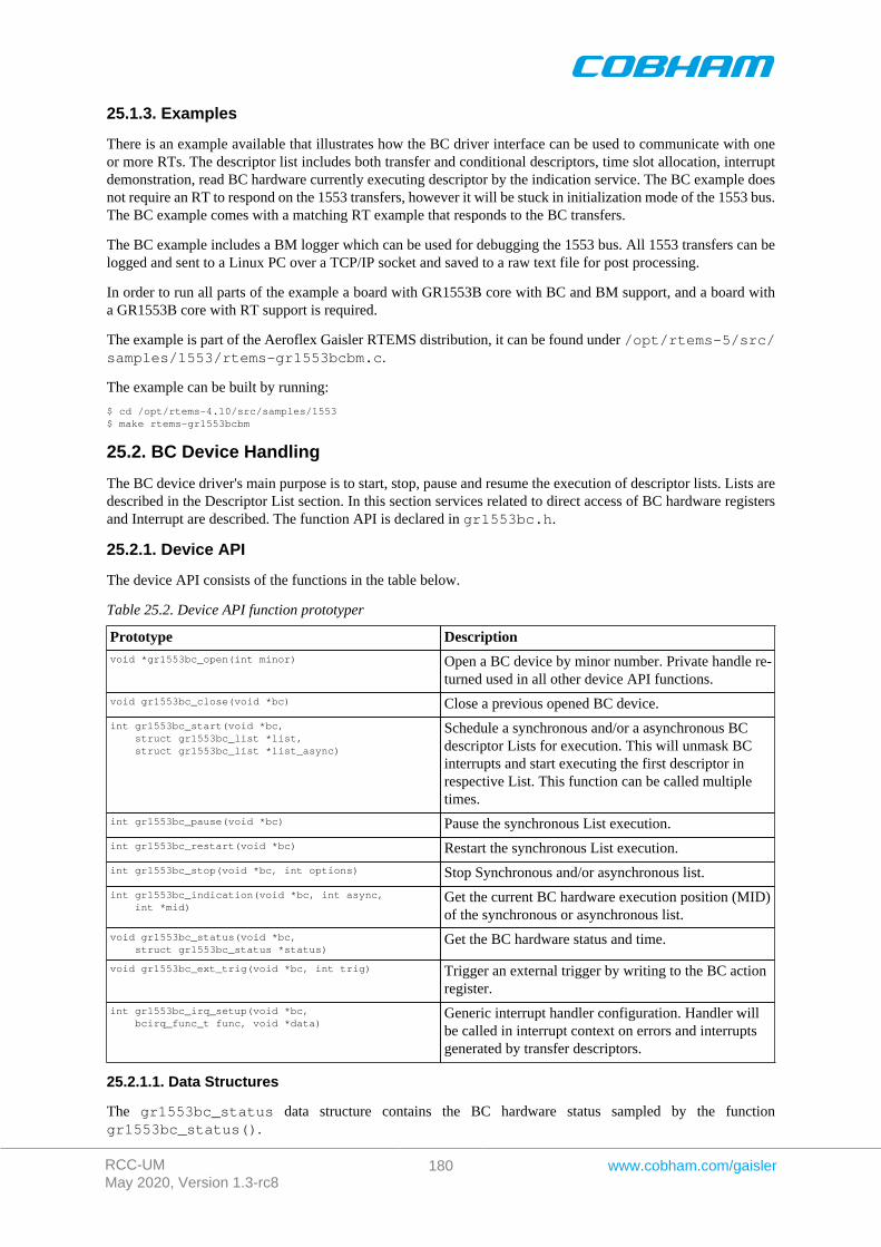
RCC-UMMay 2020, Version 1.3-rc8
180 www.cobham.com/gaisler
25.1.3. Examples
There is an example available that illustrates how the BC driver interface can be used to communicate with oneor more RTs. The descriptor list includes both transfer and conditional descriptors, time slot allocation, interruptdemonstration, read BC hardware currently executing descriptor by the indication service. The BC example doesnot require an RT to respond on the 1553 transfers, however it will be stuck in initialization mode of the 1553 bus.The BC example comes with a matching RT example that responds to the BC transfers.
The BC example includes a BM logger which can be used for debugging the 1553 bus. All 1553 transfers can belogged and sent to a Linux PC over a TCP/IP socket and saved to a raw text file for post processing.
In order to run all parts of the example a board with GR1553B core with BC and BM support, and a board witha GR1553B core with RT support is required.
The example is part of the Aeroflex Gaisler RTEMS distribution, it can be found under /opt/rtems-5/src/samples/1553/rtems-gr1553bcbm.c.
The example can be built by running:
$ cd /opt/rtems-4.10/src/samples/1553$ make rtems-gr1553bcbm
25.2. BC Device Handling
The BC device driver's main purpose is to start, stop, pause and resume the execution of descriptor lists. Lists aredescribed in the Descriptor List section. In this section services related to direct access of BC hardware registersand Interrupt are described. The function API is declared in gr1553bc.h.
25.2.1. Device API
The device API consists of the functions in the table below.
Table 25.2. Device API function prototyper
Prototype Descriptionvoid *gr1553bc_open(int minor) Open a BC device by minor number. Private handle re-
turned used in all other device API functions.
void gr1553bc_close(void *bc) Close a previous opened BC device.
int gr1553bc_start(void *bc, struct gr1553bc_list *list, struct gr1553bc_list *list_async)
Schedule a synchronous and/or a asynchronous BCdescriptor Lists for execution. This will unmask BCinterrupts and start executing the first descriptor inrespective List. This function can be called multipletimes.
int gr1553bc_pause(void *bc) Pause the synchronous List execution.
int gr1553bc_restart(void *bc) Restart the synchronous List execution.
int gr1553bc_stop(void *bc, int options) Stop Synchronous and/or asynchronous list.
int gr1553bc_indication(void *bc, int async, int *mid)
Get the current BC hardware execution position (MID)of the synchronous or asynchronous list.
void gr1553bc_status(void *bc, struct gr1553bc_status *status)
Get the BC hardware status and time.
void gr1553bc_ext_trig(void *bc, int trig) Trigger an external trigger by writing to the BC actionregister.
int gr1553bc_irq_setup(void *bc, bcirq_func_t func, void *data)
Generic interrupt handler configuration. Handler willbe called in interrupt context on errors and interruptsgenerated by transfer descriptors.
25.2.1.1. Data Structures
The gr1553bc_status data structure contains the BC hardware status sampled by the functiongr1553bc_status().
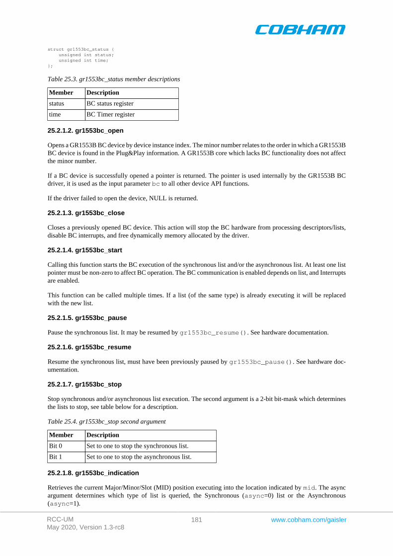
RCC-UMMay 2020, Version 1.3-rc8
181 www.cobham.com/gaisler
struct gr1553bc_status { unsigned int status; unsigned int time;};
Table 25.3. gr1553bc_status member descriptions
Member Description
status BC status register
time BC Timer register
25.2.1.2. gr1553bc_open
Opens a GR1553B BC device by device instance index. The minor number relates to the order in which a GR1553BBC device is found in the Plug&Play information. A GR1553B core which lacks BC functionality does not affectthe minor number.
If a BC device is successfully opened a pointer is returned. The pointer is used internally by the GR1553B BCdriver, it is used as the input parameter bc to all other device API functions.
If the driver failed to open the device, NULL is returned.
25.2.1.3. gr1553bc_close
Closes a previously opened BC device. This action will stop the BC hardware from processing descriptors/lists,disable BC interrupts, and free dynamically memory allocated by the driver.
25.2.1.4. gr1553bc_start
Calling this function starts the BC execution of the synchronous list and/or the asynchronous list. At least one listpointer must be non-zero to affect BC operation. The BC communication is enabled depends on list, and Interruptsare enabled.
This function can be called multiple times. If a list (of the same type) is already executing it will be replacedwith the new list.
25.2.1.5. gr1553bc_pause
Pause the synchronous list. It may be resumed by gr1553bc_resume(). See hardware documentation.
25.2.1.6. gr1553bc_resume
Resume the synchronous list, must have been previously paused by gr1553bc_pause(). See hardware doc-umentation.
25.2.1.7. gr1553bc_stop
Stop synchronous and/or asynchronous list execution. The second argument is a 2-bit bit-mask which determinesthe lists to stop, see table below for a description.
Table 25.4. gr1553bc_stop second argument
Member Description
Bit 0 Set to one to stop the synchronous list.
Bit 1 Set to one to stop the asynchronous list.
25.2.1.8. gr1553bc_indication
Retrieves the current Major/Minor/Slot (MID) position executing into the location indicated by mid. The asyncargument determines which type of list is queried, the Synchronous (async=0) list or the Asynchronous(async=1).
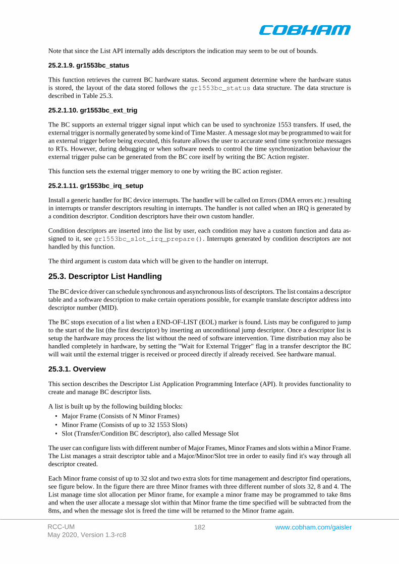
RCC-UMMay 2020, Version 1.3-rc8
182 www.cobham.com/gaisler
Note that since the List API internally adds descriptors the indication may seem to be out of bounds.
25.2.1.9. gr1553bc_status
This function retrieves the current BC hardware status. Second argument determine where the hardware statusis stored, the layout of the data stored follows the gr1553bc_status data structure. The data structure isdescribed in Table 25.3.
25.2.1.10. gr1553bc_ext_trig
The BC supports an external trigger signal input which can be used to synchronize 1553 transfers. If used, theexternal trigger is normally generated by some kind of Time Master. A message slot may be programmed to wait foran external trigger before being executed, this feature allows the user to accurate send time synchronize messagesto RTs. However, during debugging or when software needs to control the time synchronization behaviour theexternal trigger pulse can be generated from the BC core itself by writing the BC Action register.
This function sets the external trigger memory to one by writing the BC action register.
25.2.1.11. gr1553bc_irq_setup
Install a generic handler for BC device interrupts. The handler will be called on Errors (DMA errors etc.) resultingin interrupts or transfer descriptors resulting in interrupts. The handler is not called when an IRQ is generated bya condition descriptor. Condition descriptors have their own custom handler.
Condition descriptors are inserted into the list by user, each condition may have a custom function and data as-signed to it, see gr1553bc_slot_irq_prepare(). Interrupts generated by condition descriptors are nothandled by this function.
The third argument is custom data which will be given to the handler on interrupt.
25.3. Descriptor List Handling
The BC device driver can schedule synchronous and asynchronous lists of descriptors. The list contains a descriptortable and a software description to make certain operations possible, for example translate descriptor address intodescriptor number (MID).
The BC stops execution of a list when a END-OF-LIST (EOL) marker is found. Lists may be configured to jumpto the start of the list (the first descriptor) by inserting an unconditional jump descriptor. Once a descriptor list issetup the hardware may process the list without the need of software intervention. Time distribution may also behandled completely in hardware, by setting the "Wait for External Trigger" flag in a transfer descriptor the BCwill wait until the external trigger is received or proceed directly if already received. See hardware manual.
25.3.1. Overview
This section describes the Descriptor List Application Programming Interface (API). It provides functionality tocreate and manage BC descriptor lists.
A list is built up by the following building blocks:
• Major Frame (Consists of N Minor Frames)• Minor Frame (Consists of up to 32 1553 Slots)• Slot (Transfer/Condition BC descriptor), also called Message Slot
The user can configure lists with different number of Major Frames, Minor Frames and slots within a Minor Frame.The List manages a strait descriptor table and a Major/Minor/Slot tree in order to easily find it's way through alldescriptor created.
Each Minor frame consist of up to 32 slot and two extra slots for time management and descriptor find operations,see figure below. In the figure there are three Minor frames with three different number of slots 32, 8 and 4. TheList manage time slot allocation per Minor frame, for example a minor frame may be programmed to take 8msand when the user allocate a message slot within that Minor frame the time specified will be subtracted from the8ms, and when the message slot is freed the time will be returned to the Minor frame again.
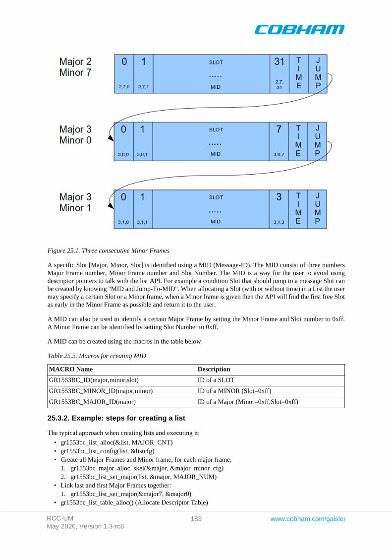
RCC-UMMay 2020, Version 1.3-rc8
183 www.cobham.com/gaisler
Figure 25.1. Three consecutive Minor Frames
A specific Slot [Major, Minor, Slot] is identified using a MID (Message-ID). The MID consist of three numbersMajor Frame number, Minor Frame number and Slot Number. The MID is a way for the user to avoid usingdescriptor pointers to talk with the list API. For example a condition Slot that should jump to a message Slot canbe created by knowing "MID and Jump-To-MID". When allocating a Slot (with or without time) in a List the usermay specify a certain Slot or a Minor frame, when a Minor frame is given then the API will find the first free Slotas early in the Minor Frame as possible and return it to the user.
A MID can also be used to identify a certain Major Frame by setting the Minor Frame and Slot number to 0xff.A Minor Frame can be identified by setting Slot Number to 0xff.
A MID can be created using the macros in the table below.
Table 25.5. Macros for creating MID
MACRO Name Description
GR1553BC_ID(major,minor,slot) ID of a SLOT
GR1553BC_MINOR_ID(major,minor) ID of a MINOR (Slot=0xff)
GR1553BC_MAJOR_ID(major) ID of a Major (Minor=0xff,Slot=0xff)
25.3.2. Example: steps for creating a list
The typical approach when creating lists and executing it:
• gr1553bc_list_alloc(&list, MAJOR_CNT)• gr1553bc_list_config(list, &listcfg)• Create all Major Frames and Minor frame, for each major frame:
1. gr1553bc_major_alloc_skel(&major, &major_minor_cfg)2. gr1553bc_list_set_major(list, &major, MAJOR_NUM)
• Link last and first Major Frames together:1. gr1553bc_list_set_major(&major7, &major0)
• gr1553bc_list_table_alloc() (Allocate Descriptor Table)
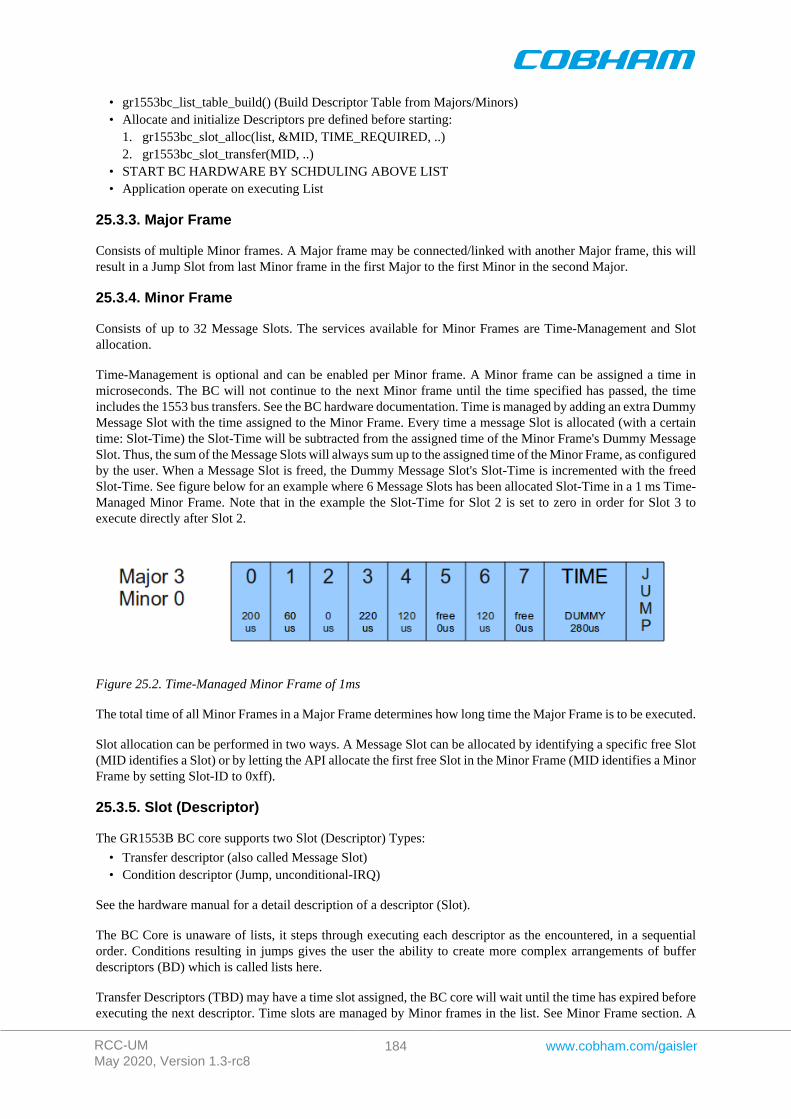
RCC-UMMay 2020, Version 1.3-rc8
184 www.cobham.com/gaisler
• gr1553bc_list_table_build() (Build Descriptor Table from Majors/Minors)• Allocate and initialize Descriptors pre defined before starting:
1. gr1553bc_slot_alloc(list, &MID, TIME_REQUIRED, ..)2. gr1553bc_slot_transfer(MID, ..)
• START BC HARDWARE BY SCHDULING ABOVE LIST• Application operate on executing List
25.3.3. Major Frame
Consists of multiple Minor frames. A Major frame may be connected/linked with another Major frame, this willresult in a Jump Slot from last Minor frame in the first Major to the first Minor in the second Major.
25.3.4. Minor Frame
Consists of up to 32 Message Slots. The services available for Minor Frames are Time-Management and Slotallocation.
Time-Management is optional and can be enabled per Minor frame. A Minor frame can be assigned a time inmicroseconds. The BC will not continue to the next Minor frame until the time specified has passed, the timeincludes the 1553 bus transfers. See the BC hardware documentation. Time is managed by adding an extra DummyMessage Slot with the time assigned to the Minor Frame. Every time a message Slot is allocated (with a certaintime: Slot-Time) the Slot-Time will be subtracted from the assigned time of the Minor Frame's Dummy MessageSlot. Thus, the sum of the Message Slots will always sum up to the assigned time of the Minor Frame, as configuredby the user. When a Message Slot is freed, the Dummy Message Slot's Slot-Time is incremented with the freedSlot-Time. See figure below for an example where 6 Message Slots has been allocated Slot-Time in a 1 ms Time-Managed Minor Frame. Note that in the example the Slot-Time for Slot 2 is set to zero in order for Slot 3 toexecute directly after Slot 2.
Figure 25.2. Time-Managed Minor Frame of 1ms
The total time of all Minor Frames in a Major Frame determines how long time the Major Frame is to be executed.
Slot allocation can be performed in two ways. A Message Slot can be allocated by identifying a specific free Slot(MID identifies a Slot) or by letting the API allocate the first free Slot in the Minor Frame (MID identifies a MinorFrame by setting Slot-ID to 0xff).
25.3.5. Slot (Descriptor)
The GR1553B BC core supports two Slot (Descriptor) Types:
• Transfer descriptor (also called Message Slot)• Condition descriptor (Jump, unconditional-IRQ)
See the hardware manual for a detail description of a descriptor (Slot).
The BC Core is unaware of lists, it steps through executing each descriptor as the encountered, in a sequentialorder. Conditions resulting in jumps gives the user the ability to create more complex arrangements of bufferdescriptors (BD) which is called lists here.
Transfer Descriptors (TBD) may have a time slot assigned, the BC core will wait until the time has expired beforeexecuting the next descriptor. Time slots are managed by Minor frames in the list. See Minor Frame section. A

RCC-UMMay 2020, Version 1.3-rc8
185 www.cobham.com/gaisler
Message Slot generating a data transmission on the 1553 bus must have a valid data pointer, pointing to a locationfrom which the BC will read or write data.
A Slot is allocated using the gr1553bc_slot_alloc() function, and configured by calling one of the functiondescribed in the table below. A Slot may be reconfigured later. Note that a conditional descriptor does not have atime slot, allocating a time for a conditional times slot will lead to an incorrect total time of the Minor Frame.
Table 25.6. Slot configuration
Function Name Description
gr1553bc_slot_irq_prepareUnconditional IRQ slot
gr1553bc_slot_jump Unconditional jump
gr1553bc_slot_exttrig Dummy transfer, wait for EXTERNAL-TRIGGER
gr1553bc_slot_transfer Transfer descriptor
gr1553bc_slot_empty Create Dummy Transfer descriptor
gr1553bc_slot_raw Custom Descriptor handling
Existing configured Slots can be manipulated with the following functions.
Table 25.7. Slot manipulation
Function Name Description
gr1553bc_slot_dummy Set existing Transfer descriptor to Dummy. No 1553 bus transfer will be per-formed.
gr1553bc_slot_update Update Data Pointer and/or Status of a TBD
25.3.6. Changing a scheduled BC list (during BC-runtime)
Changing a descriptor that is being executed by the BC may result in a race between hardware and software. Oneof the problems is that a descriptor contains multiple words, which can not be written simultaneously by the CPU.To avoid the problem one can use the INDICATION service to avoid modifying a descriptor currently in use by theBC core. The indication service tells the user which Major/Minor/ Slot is currently being executed by hardware,from that information an knowing the list layout and time slots the user may safely select which slot to modifyor wait until hardware is finished.
In most cases one can do descriptor initialization in several steps to avoid race conditions. By initializing (allocatingand configuring) a Slot before starting the execution of the list, one may change parts of the descriptor whichare ignored by the hardware. Below is an example approach that will avoid potential races between software andhardware:
1. Initialize Descriptor as Dummy and allocated time (often done before starting/ scheduling list)2. The list is started, as a result descriptors in the list are executed by the BC3. Modify transfer options and data-pointers, but maintain the Dummy bit.4. Clear the Dummy bit in one atomic data store.
25.3.7. Custom Memory Setup
For designs where dynamically memory is not an option, or the driver is used on an AMBA-over-PCI bus (wheremalloc() does not work), the API allows the user to provide custom addresses for the descriptor table and objectdescriptions (lists, major frames, minor frames).
Being able to configure a custom descriptor table may for example be used to save space or put the descriptor tablein on-chip memory. The descriptor table is setup using the function gr1553bc_list_table_alloc(list,CUSTOM_ADDRESS).
Object descriptions are normally allocated during initialization procedure by providing the API with an objectconfiguration, for example a Major Frame configuration enables the API to dynamically allocate the softwaredescription of the Major Frame and with all it's Minor frames. Custom object allocation requires internal under-standing of the List management parts of the driver, it is not described in this document.
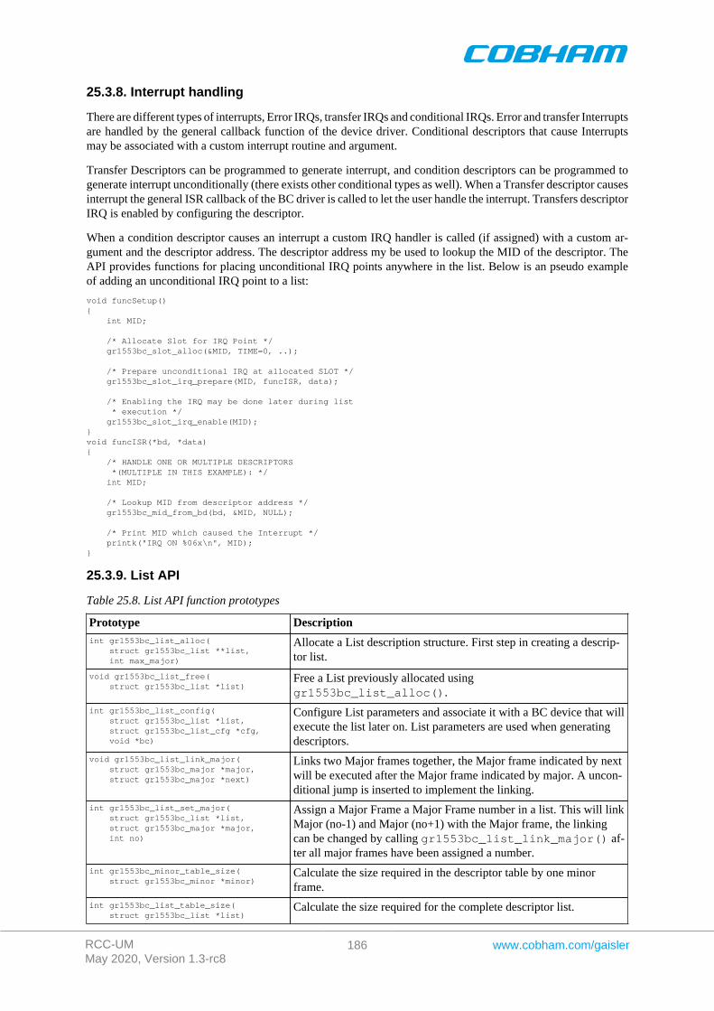
RCC-UMMay 2020, Version 1.3-rc8
186 www.cobham.com/gaisler
25.3.8. Interrupt handling
There are different types of interrupts, Error IRQs, transfer IRQs and conditional IRQs. Error and transfer Interruptsare handled by the general callback function of the device driver. Conditional descriptors that cause Interruptsmay be associated with a custom interrupt routine and argument.
Transfer Descriptors can be programmed to generate interrupt, and condition descriptors can be programmed togenerate interrupt unconditionally (there exists other conditional types as well). When a Transfer descriptor causesinterrupt the general ISR callback of the BC driver is called to let the user handle the interrupt. Transfers descriptorIRQ is enabled by configuring the descriptor.
When a condition descriptor causes an interrupt a custom IRQ handler is called (if assigned) with a custom ar-gument and the descriptor address. The descriptor address my be used to lookup the MID of the descriptor. TheAPI provides functions for placing unconditional IRQ points anywhere in the list. Below is an pseudo exampleof adding an unconditional IRQ point to a list:
void funcSetup(){ int MID;
/* Allocate Slot for IRQ Point */ gr1553bc_slot_alloc(&MID, TIME=0, ..);
/* Prepare unconditional IRQ at allocated SLOT */ gr1553bc_slot_irq_prepare(MID, funcISR, data);
/* Enabling the IRQ may be done later during list * execution */ gr1553bc_slot_irq_enable(MID);}void funcISR(*bd, *data){ /* HANDLE ONE OR MULTIPLE DESCRIPTORS *(MULTIPLE IN THIS EXAMPLE): */ int MID;
/* Lookup MID from descriptor address */ gr1553bc_mid_from_bd(bd, &MID, NULL);
/* Print MID which caused the Interrupt */ printk("IRQ ON %06x\n", MID);}
25.3.9. List API
Table 25.8. List API function prototypes
Prototype Descriptionint gr1553bc_list_alloc( struct gr1553bc_list **list, int max_major)
Allocate a List description structure. First step in creating a descrip-tor list.
void gr1553bc_list_free( struct gr1553bc_list *list)
Free a List previously allocated usinggr1553bc_list_alloc().
int gr1553bc_list_config( struct gr1553bc_list *list, struct gr1553bc_list_cfg *cfg, void *bc)
Configure List parameters and associate it with a BC device that willexecute the list later on. List parameters are used when generatingdescriptors.
void gr1553bc_list_link_major( struct gr1553bc_major *major, struct gr1553bc_major *next)
Links two Major frames together, the Major frame indicated by nextwill be executed after the Major frame indicated by major. A uncon-ditional jump is inserted to implement the linking.
int gr1553bc_list_set_major( struct gr1553bc_list *list, struct gr1553bc_major *major, int no)
Assign a Major Frame a Major Frame number in a list. This will linkMajor (no-1) and Major (no+1) with the Major frame, the linkingcan be changed by calling gr1553bc_list_link_major() af-ter all major frames have been assigned a number.
int gr1553bc_minor_table_size( struct gr1553bc_minor *minor)
Calculate the size required in the descriptor table by one minorframe.
int gr1553bc_list_table_size( struct gr1553bc_list *list)
Calculate the size required for the complete descriptor list.
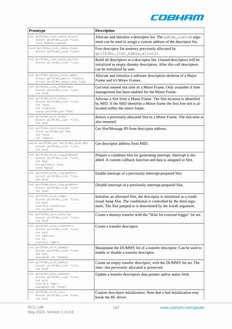
RCC-UMMay 2020, Version 1.3-rc8
187 www.cobham.com/gaisler
Prototype Descriptionint gr1553bc_list_table_alloc( struct gr1553bc_list *list, void *bdtab_custom)
Allocate and initialize a descriptor list. The bdtab_custom argu-ment can be used to assign a custom address of the descriptor list.
void gr1553bc_list_table_free( struct gr1553bc_list *list)
Free descriptor list memory previously allocated bygr1553bc_list_table_alloc().
int gr1553bc_list_table_build( struct gr1553bc_list *list)
Build all descriptors in a descriptor list. Unused descriptors will beinitialized as empty dummy descriptors. After this call descriptorscan be initialized by user.
int gr1553bc_major_alloc_skel( struct gr1553bc_major **major, struct gr1553bc_major_cfg *cfg)
Allocate and initialize a software description skeleton of a MajorFrame and it's Minor Frames.
int gr1553bc_list_freetime( struct gr1553bc_list *list, int mid)
Get total unused slot time of a Minor Frame. Only available if timemanagement has been enabled for the Minor Frame.
int gr1553bc_slot_alloc( struct gr1553bc_list *list, int *mid, int timeslot, union gr1553bc_bd **bd)
Allocate a Slot from a Minor Frame. The Slot location is identifiedby MID. If the MID identifies a Minor frame the first free slot is al-located within the minor frame.
int gr1553bc_slot_free( struct gr1553bc_list *list, int mid)
Return a previously allocated Slot to a Minor Frame. The slot-time isalso returned.
int gr1553bc_mid_from_bd( union gr1553bc_bd *bd, int *mid, int *async)
Get Slot/Message ID from descriptor address.
union gr1553bc_bd *gr1553bc_slot_bd( struct gr1553bc_list *list, int mid)
Get descriptor address from MID.
int gr1553bc_slot_irq_prepare( struct gr1553bc_list *list, int mid, bcirq_func_t func, void *data)
Prepare a condition Slot for generating interrupt. Interrupt is dis-abled. A custom callback function and data is assigned to Slot.
int gr1553bc_slot_irq_enable( struct gr1553bc_list *list, int mid)
Enable interrupt of a previously interrupt-prepared Slot.
int gr1553bc_slot_irq_disable( struct gr1553bc_list *list, int mid)
Disable interrupt of a previously interrupt-prepared Slot.
int gr1553bc_slot_jump( struct gr1553bc_list *list, int mid, uint32_t condition, int to_mid)
Initialize an allocated Slot, the descriptor is initialized as a condi-tional Jump Slot. The conditional is controlled by the third argu-ment. The Slot jumped to is determined by the fourth argument.
int gr1553bc_slot_exttrig( struct gr1553bc_list *list, int mid)
Create a dummy transfer with the "Wait for external trigger" bit set.
int gr1553bc_slot_transfer( struct gr1553bc_list *list, int mid, int options, int tt, uint16_t *dptr)
Create a transfer descriptor.
int gr1553bc_slot_dummy( struct gr1553bc_list *list, int mid, unsigned int *dummy)
Manipulate the DUMMY bit of a transfer descriptor. Can be used toenable or disable a transfer descriptor.
int gr1553bc_slot_empty( struct gr1553bc_list *list, int mid)
Create an empty transfer descriptor, with the DUMMY bit set. Thetime- slot previously allocated is preserved.
int gr1553bc_slot_update( struct gr1553bc_list *list, int mid, uint16_t *dptr, unsigned int *stat)
Update a transfer descriptors data pointer and/or status field.
int gr1553bc_slot_raw( struct gr1553bc_list *list, int mid,
Custom descriptor initialization. Note that a bad initialization maybreak the BC driver.
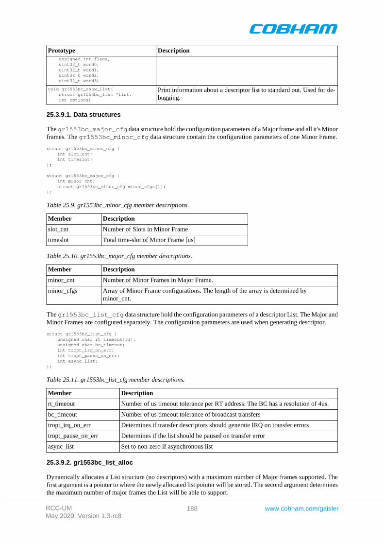
RCC-UMMay 2020, Version 1.3-rc8
188 www.cobham.com/gaisler
Prototype Description unsigned int flags, uint32_t word0, uint32_t word1, uint32_t word2, uint32_t word3)
void gr1553bc_show_list( struct gr1553bc_list *list, int options)
Print information about a descriptor list to standard out. Used for de-bugging.
25.3.9.1. Data structures
The gr1553bc_major_cfg data structure hold the configuration parameters of a Major frame and all it's Minorframes. The gr1553bc_minor_cfg data structure contain the configuration parameters of one Minor Frame.
struct gr1553bc_minor_cfg { int slot_cnt; int timeslot;};
struct gr1553bc_major_cfg { int minor_cnt; struct gr1553bc_minor_cfg minor_cfgs[1];};
Table 25.9. gr1553bc_minor_cfg member descriptions.
Member Description
slot_cnt Number of Slots in Minor Frame
timeslot Total time-slot of Minor Frame [us]
Table 25.10. gr1553bc_major_cfg member descriptions.
Member Description
minor_cnt Number of Minor Frames in Major Frame.
minor_cfgs Array of Minor Frame configurations. The length of the array is determined byminor_cnt.
The gr1553bc_list_cfg data structure hold the configuration parameters of a descriptor List. The Major andMinor Frames are configured separately. The configuration parameters are used when generating descriptor.
struct gr1553bc_list_cfg { unsigned char rt_timeout[31]; unsigned char bc_timeout; int tropt_irq_on_err; int tropt_pause_on_err; int async_list;};
Table 25.11. gr1553bc_list_cfg member descriptions.
Member Description
rt_timeout Number of us timeout tolerance per RT address. The BC has a resolution of 4us.
bc_timeout Number of us timeout tolerance of broadcast transfers
tropt_irq_on_err Determines if transfer descriptors should generate IRQ on transfer errors
tropt_pause_on_err Determines if the list should be paused on transfer error
async_list Set to non-zero if asynchronous list
25.3.9.2. gr1553bc_list_alloc
Dynamically allocates a List structure (no descriptors) with a maximum number of Major frames supported. Thefirst argument is a pointer to where the newly allocated list pointer will be stored. The second argument determinesthe maximum number of major frames the List will be able to support.

RCC-UMMay 2020, Version 1.3-rc8
189 www.cobham.com/gaisler
The list is initialized according to the default configuration.
If the list allocation fails, a negative result will be returned.
25.3.9.3. gr1553bc_list_free
Free a List that has been previously allocated with gr1553bc_list_alloc().
25.3.9.4. gr1553bc_list_config
This function configures List parameters and associate the list with a BC device. The BC device may be used totranslate addresses from CPU address to addresses the GR1553B core understand, therefore the list must not bescheduled on another BC device.
Some of the List parameters are used when generating descriptors, as global descriptor parameters. For exampleall transfer descriptors to a specific RT result in the same time out settings.
The first argument points to a list that is configure. The second argument points to the configuration description,the third argument identifies the BC device that the list will be scheduled on. The layout of the list configurationis described in Table 25.11.
25.3.9.5. gr1553bc_list_link_major
At the end of a Major Frame a unconditional jump to the next Major Frame is inserted by the List API. The ListAPI assumes that a Major Frame should jump to the following Major Frame, however for the last Major Framethe user must tell the API which frame to jump to. The user may also connect Major frames in a more complexway, for example Major Frame 0 and 1 is executed only once so the last Major frame jumps to Major Frame 2.
The Major frame indicated by next will be executed after the Major frame indicated by major. A unconditionaljump is inserted to implement the linking.
25.3.9.6. gr1553bc_list_set_major
Major Frames are associated with a number, a Major Frame Number. This function creates an association betweena Frame and a Number, all Major Frames must be assigned a number within a List.
The function will link Major[no-1] and Major[no+1] with the Major frame, the linking can be changed by callinggr1553bc_list_link_major() after all major frames have been assigned a number.
25.3.9.7. gr1553bc_minor_table_size
This function is used internally by the List API, however it can also be used in an application to calculate the spacerequired by descriptors of a Minor Frame.
The total size of all descriptors in one Minor Frame (in number of bytes) is returned. Descriptors added internallyby the List API are also counted.
25.3.9.8. gr1553bc_list_table_size
This function is used internally by the List API, however it can also be used in an application to calculate the totalspace required by all descriptors of a List.
The total descriptor size of all Major/Minor Frames of the list (in number of bytes) is returned.
25.3.9.9. gr1553bc_list_table_alloc
This function allocates all descriptors needed by a List, either dynamically or by a user provided address. The Listis initialized with the new descriptor table, i.e. the software's internal representation is initialized. The descriptorsthemselves are not initialized.
The second argument bdtab_custom determines the allocation method. If NULL the API will allocate memoryusing malloc(), if non-zero the value will be taken as the base descriptor address. If bit zero is set the address

RCC-UMMay 2020, Version 1.3-rc8
190 www.cobham.com/gaisler
is assumed to be readable by the GR1553B core, if bit zero is cleared the address is assumed to be readable bythe CPU and translated for the GR1553B core. Bit zero makes sense to use on a GR1553B core located on aAMBA-over-PCI bus.
If memory allocation fails (in case of dynamic memory allocation) the function return -1, it returns -2 if the memoryis not aligned or on success zero is returned.
25.3.9.10. gr1553bc_list_table_free
Free previously allocated descriptor table memory.
25.3.9.11. gr1553bc_list_table_build
This function builds all descriptors in a descriptor list. Unused descriptors will be initialized as empty dummydescriptors. Jumps between Minor and Major Frames will be created according to user configuration.
After this call descriptors can be initialized by user.
25.3.9.12. gr1553bc_major_alloc_skel
Allocate a Major Frame and it's Minor Frames according to the configuration pointed to by the second argument.
The pointer to the allocated Major Frame is stored into the location pointed to by the major argument.
The configuration of the Major Frame is determined by the gr1553bc_major_cfg structure, described in Ta-ble 25.10.
On success zero is returned, on failure a negative value is returned.
25.3.9.13. gr1553bc_list_freetime
Minor Frames can be configured to handle time slot allocation. This function returns the number of microsecondsthat is left/unused. The second argument mid determines which Minor Frame.
25.3.9.14. gr1553bc_slot_alloc
Allocate a Slot from a Minor Frame. The Slot location is identified by mid. If the MID identifies a Minor framethe first free slot is allocated within the minor frame.
The resulting MID of the Slot is stored back to mid, the MID can be used in other function call when setting upthe Slot. The mid argument is thus of in and out type.
The third argument, timeslot, determines the time slot that should be allocated to the Slot. If time managementis not configured for the Minor Frame a time can still be assigned to the Slot. If the Slot should step to the next Slotdirectly when finished (no assigned time-slot), the argument must be set to zero. If time management is enabled forthe Minor Frame and the requested time-slot is longer than the free time, the call will result in an error (negativeresult).
The fourth and last argument can optionally be used to get the address of the descriptor used.
25.3.9.15. gr1553bc_slot_free
Return Slot and timeslot allocated from the Minor Frame.
25.3.9.16. gr1553bc_mid_from_bd
Looks up the Slot/Message ID (MID) from a descriptor address. This function may be useful in the interrupthandler, where the address of the descriptor is given.
25.3.9.17. gr1553bc_slot_bd
Looks up descriptor address from MID.
RCC-UMMay 2020, Version 1.3-rc8
191 www.cobham.com/gaisler
25.3.9.18. gr1553bc_slot_irq_prepare
Prepares a condition descriptor to generate interrupt. Interrupt will not be enabled untilgr1553bc_slot_irq_enable() is called. The descriptor will be initialized as an unconditional jump tothe next descriptor. The Slot can be associated with a custom callback function and an argument. The callbackfunction and argument is stored in the unused fields of the descriptor.
Once enabled and interrupt is generated by the Slot, the callback routine will be called from interrupt context.
The function returns a negative result if failure, otherwise zero is returned.
25.3.9.19. gr1553bc_slot_irq_enable
Enables interrupt of a previously prepared unconditional jump Slot. The Slot is expected to be initialized withgr1553bc_slot_irq_prepare(). The descriptor is changed to do a unconditional jump with interrupt.
The function returns a negative result if failure, otherwise zero is returned.
25.3.9.20. gr1553bc_slot_irq_disable
Disable unconditional IRQ point, the descriptor is changed to unconditional JUMP to the following descriptor,without generating interrupt. After disabling the Slot it can be enabled again, or freed.
The function returns a negative result if failure, otherwise zero is returned.
25.3.9.21. gr1553bc_slot_jump
Initialize a Slot with a custom jump condition. The arguments are declared in the table below.
Table 25.12. gr1553bc_list_cfg member descriptions.
Argument Description
list List that the Slot is located at.
mid Slot Identification.
condition Custom condition written to descriptor. See hardware documentation for options.
to_mid Slot Identification of the Slot that the descriptor will be jumping to.
Returns zero on success.
25.3.9.22. gr1553bc_slot_exttrig
The BC supports an external trigger signal input which can be used to synchronize 1553 transfers. If used, theexternal trigger is normally generated by some kind of Time Master. A message slot may be programmed towait for an external trigger before being executed, this feature allows the user to accurate send time synchronizemessages to RTs.
This function initializes a Slot to a dummy transfer with the "Wait for external trigger" bit set.
Returns zero on success.
25.3.9.23. gr1553bc_slot_transfer
Initializes a descriptor to a transfer descriptor. The descriptor is initialized according to the function arguments anthe global List configuration parameters. The settings that are controlled on a global level (and not by this function):
• IRQ after transfer error• IRQ after transfer (not supported, insert separate IRQ slot after this)• Pause schedule after transfer error• Pause schedule after transfer (not supported)• Slot time optional (set when MID allocated), otherwise 0
RCC-UMMay 2020, Version 1.3-rc8
192 www.cobham.com/gaisler
• (OPTIONAL) Dummy Bit, set using slot_empty() or ..._TT_DUMMY• RT time out tolerance (managed per RT)
The arguments are declared in the table below.
Table 25.13. gr1553bc_slot_transfer argument descriptions.
Argument Description
list List that the Slot is located at
mid Slot Identification
options Options:
• Retry Mode• Number of retires• Bus selection (A or B)• Dummy bit
tt Transfer options, see BC transfer type macros in header file:
• transfer type• RT src/dst address• RT subaddress• word count• mode code
dptr Descriptor Data Pointer. Used by Hardware to read or write data to the 1553 bus. If bit zero isset the address is translated by the driver into an address which the hardware can access(maybe the case if BC device is located on an AMBA-over-PCI bus), if cleared it is assumed thatno translation is required(typical case)
Returns zero on success.
25.3.9.24. gr1553bc_slot_dummy
Manipulate the DUMMY bit of a transfer descriptor. Can be used to enable or disable a transfer descriptor.
The dummy argument points to an area used as input and output, as input bit 31 is written to the dummy bit of thedescriptor, as output the old value of the descriptor's dummy bit is written.
Returns zero on success.
25.3.9.25. gr1553bc_slot_empty
Create an empty transfer descriptor, with the DUMMY bit set. The time-slot previously allocated is preserved.
Returns zero on success.
25.3.9.26. gr1553bc_slot_update
This function will update a transfer descriptor's status and/or update the data pointer.
If the dptr pointer is non-zero the Data Pointer word of the descriptor will be updated with the value of dptr.If bit zero is set the driver will translate the data pointer address into an address accessible by the BC hardware.Translation is an option only for AMBA-over-PCI.
If the stat pointer is non-zero the Status word of the descriptor will be updated according to the content of stat.The old Status will be stored into stat. The lower 24-bits of the current Status word may be cleared, and thedummy bit may be set:
bd->status = *stat & (bd->status 0xffffff) | (*stat & 0x80000000);
Note that the status word is not written (only read) when value pointed to by stat is zero.
RCC-UMMay 2020, Version 1.3-rc8
193 www.cobham.com/gaisler
Returns zero on success.
25.3.9.27. gr1553bc_slot_raw
Custom descriptor initialization. Note that a bad initialization may break the BC driver.
The arguments are declared in the table below.
Table 25.14. gr1553bc_slot_transfer argument descriptions.
Argument Description
list List that the Slot is located at
mid Slot Identification
flags Determine which words are updated. If bit N is set wordN is written into descriptor wordN, ifbit N is zero the descriptor wordN is not modified.
word0 32-bit Word written to descriptor address 0x00
word1 32-bit Word written to descriptor address 0x04
word2 32-bit Word written to descriptor address 0x08
word3 32-bit Word written to descriptor address 0x0C
Returns zero on success.
25.3.9.28. gr1553bc_show_list
Print information about a List to standard out. Each Major Frame's first descriptor for example is printed. Thisfunction is used for debugging only.
RCC-UMMay 2020, Version 1.3-rc8
194 www.cobham.com/gaisler
Chapter 26. B1553BRM GRLIB Actel Core1553BRM driver
26.1. Introduction
This document is intended as an aid in getting started developing with GRLIB B1553BRM core using the driverdescribed in this document. It briefly takes the reader through some of the most important steps in using the driversuch as setting up a connection, configuring the driver, reading and writing messages between Bus Controllers(BC), Remote Terminals (RT) and Bus Monitors (BM). The reader is assumed to be well acquainted with MIL-STD-1553 and RTEMS.
The B1553BRM driver require the RTEMS Driver Manager.
26.1.1. BRM Hardware
The BRM hardware can operate in one of three modes, Bus Controller (BC), Remote Terminal (RT) or BusMonitor (BM). All three modes are supported by the driver. The software interface of the BRM-RT is similar tothe B1553RT software interface to simplify software development.
The B1553BRM core is present in GR712RC. In many newer systems the GR1553B IP core replaces theB1553BRM which has a different software interface documented in the Chapter 22.
26.1.2. Software Driver
The driver provides means for processes and threads to send, receive and monitor messages.
• Bus Controller• Remote Terminal• Bus monitor
26.1.3. Supported OS
There is a simple example available it illustrates how to set up a connection between a BC and a RT monitored bya BM. The BC sends the RT receive and transmit messages for a number of different sub addresses. The BM isset up to print messages from the BC and the RT. To be able to run the example one must have at least two boardsconnected together via the B1553BRM interfaces. To fully run the example three BRM boards is needed.
The example is part of the Gaisler RTEMS distribution, it can be found under /opt/rtems-5/src/sam-ples/rtems-brm.c, brm_lib.c and brm_lib.h.
The example can be built by running:
cd /opt/rtems-5/src/samples make clean rtems-brm_rt rtems-brm_bc rtems-brm_bm
26.2. User Intrerface
The RTEMS MIL-STD-1553B BRM driver supports standard accesses to file descriptors such as read, writeand ioctl. User applications include the [brm] driver's header file which contains definitions of all necessary datastructures and bit masks used when accessing the driver. An example application using the driver is provided inthe examples directory.
The driver for the MIL-STD-1553 B BRM has three different operating modes, Remote Terminal, Bus Controlleror Bus Monitor. It defaults to Remote Terminal (RT) with address 1, MIL- STD-1553 B standard, both busesenabled, and broadcasts enabled. The operating mode and settings can be changed with ioctl calls as describedlater.
26.2.1. Driver registration
The registration of the driver is crucial for threads and processes to be able to access the driver using stan-dard means, such as open. The RTEMS I/O driver registration is performed automatically by the driver whenB1553BRM hardware is found for the first time. The driver is called from the driver manager to handle detected
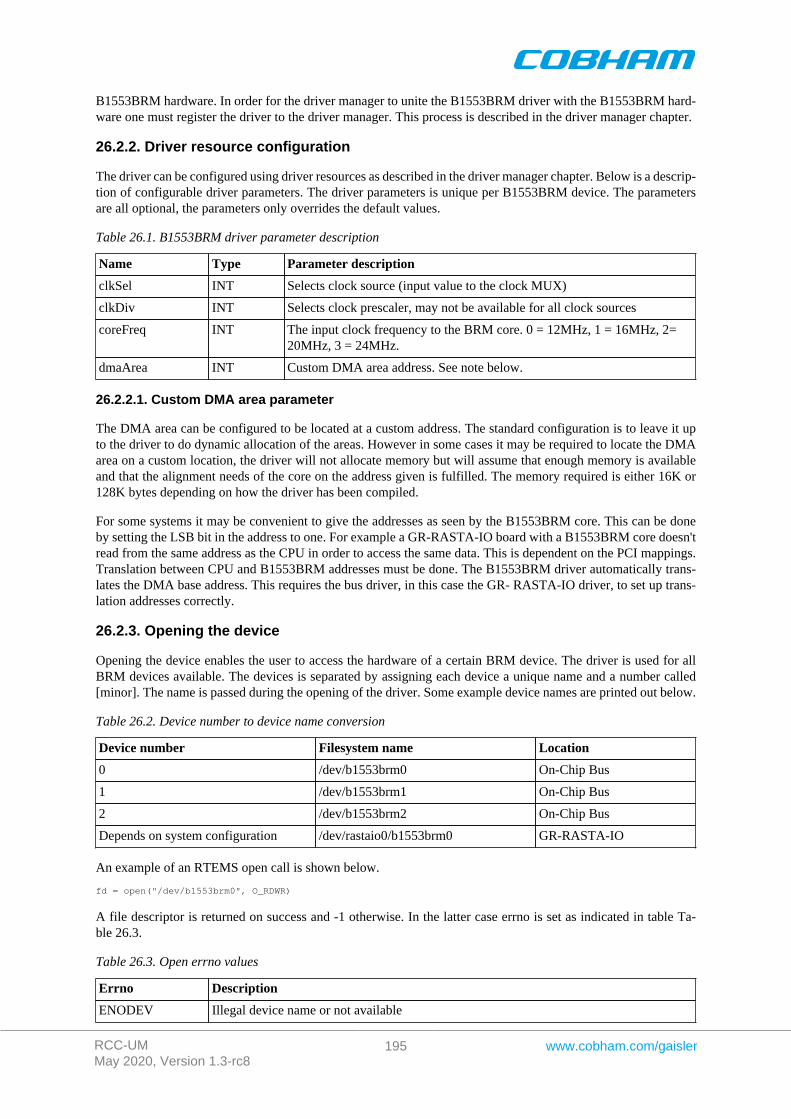
RCC-UMMay 2020, Version 1.3-rc8
195 www.cobham.com/gaisler
B1553BRM hardware. In order for the driver manager to unite the B1553BRM driver with the B1553BRM hard-ware one must register the driver to the driver manager. This process is described in the driver manager chapter.
26.2.2. Driver resource configuration
The driver can be configured using driver resources as described in the driver manager chapter. Below is a descrip-tion of configurable driver parameters. The driver parameters is unique per B1553BRM device. The parametersare all optional, the parameters only overrides the default values.
Table 26.1. B1553BRM driver parameter description
Name Type Parameter description
clkSel INT Selects clock source (input value to the clock MUX)
clkDiv INT Selects clock prescaler, may not be available for all clock sources
coreFreq INT The input clock frequency to the BRM core. 0 = 12MHz, 1 = 16MHz, 2=20MHz, 3 = 24MHz.
dmaArea INT Custom DMA area address. See note below.
26.2.2.1. Custom DMA area parameter
The DMA area can be configured to be located at a custom address. The standard configuration is to leave it upto the driver to do dynamic allocation of the areas. However in some cases it may be required to locate the DMAarea on a custom location, the driver will not allocate memory but will assume that enough memory is availableand that the alignment needs of the core on the address given is fulfilled. The memory required is either 16K or128K bytes depending on how the driver has been compiled.
For some systems it may be convenient to give the addresses as seen by the B1553BRM core. This can be doneby setting the LSB bit in the address to one. For example a GR-RASTA-IO board with a B1553BRM core doesn'tread from the same address as the CPU in order to access the same data. This is dependent on the PCI mappings.Translation between CPU and B1553BRM addresses must be done. The B1553BRM driver automatically trans-lates the DMA base address. This requires the bus driver, in this case the GR- RASTA-IO driver, to set up trans-lation addresses correctly.
26.2.3. Opening the device
Opening the device enables the user to access the hardware of a certain BRM device. The driver is used for allBRM devices available. The devices is separated by assigning each device a unique name and a number called[minor]. The name is passed during the opening of the driver. Some example device names are printed out below.
Table 26.2. Device number to device name conversion
Device number Filesystem name Location
0 /dev/b1553brm0 On-Chip Bus
1 /dev/b1553brm1 On-Chip Bus
2 /dev/b1553brm2 On-Chip Bus
Depends on system configuration /dev/rastaio0/b1553brm0 GR-RASTA-IO
An example of an RTEMS open call is shown below.
fd = open("/dev/b1553brm0", O_RDWR)
A file descriptor is returned on success and -1 otherwise. In the latter case errno is set as indicated in table Ta-ble 26.3.
Table 26.3. Open errno values
Errno Description
ENODEV Illegal device name or not available
RCC-UMMay 2020, Version 1.3-rc8
196 www.cobham.com/gaisler
Errno Description
EBUSY Device already opened
26.2.4. Closing the device
The device is closed using the close call. An example is shown below.
res = close(fd)
Close always returns 0 (success) for the [brm] driver.
26.2.5. I/O Control interface
Changing the behaviour of the driver for a device is done via the standard system call ioctl. Most operating systemssupport at least two arguments to ioctl, the first being an integer which selects ioctl function and secondly a pointerto data that may be interpreted uniquely for each function. A typical ioctl call definition:
int ioctl(int fd, int cmd, void *arg);
The return value is 0 on success and -1 on failure and the global [errno] variable is set accordingly.
All supported commands and their data structures are defined in the BRM driver's header file [brm.h]. In functionswhere only one argument is needed the pointer (...,void *arg) may be converted to an integer and interpreteddirectly, thus simplifying the code.
26.2.5.1. Data structures
26.2.5.1.1. Remote Terminal operating mode
The structure below is used for RT operating mode for all received events as well as to put data in the transmitbuffer.
struct rt_msg { unsigned short miw; unsigned short time; unsigned short data[32]; unsigned short desc;};
Table 26.4. rt_msg member descriptions.
Member Description
miwBit(s) Description
15-11 Word count / mode code - For subaddresses this is the number ofreceived words. For mode codes it is the receive/transmit modecode.
10 -
9 A/B - 1 if message receive on bus A, 0 if received on bus B.
8 RTRT - 1 if message is part of an RT to RT transfer
7 ME - 1 if an error was encountered during message processing. Bit4-0 gives the details of the error.
6-5 -
4 ILL - 1 if received command is illegalized.
3 TO - If set, the number of received words was less than the amountspecified by the word count.
2 OVR - If set, the number of received words was more than amountspecified by the word count.
1 PRTY - 1 if the RT detected a parity error in the received data.
RCC-UMMay 2020, Version 1.3-rc8
197 www.cobham.com/gaisler
Member Description
Bit(s) Description
0 MAN - 1 if a Manchester decoding error was detected during datareception.
time Time Tag - Contains the value of the internal timer register when the message was re-ceived.
data An array of 32 16 bit words. The word count specifies how many data words that arevalid. For receive mode codes with data the first data word is valid.
desc Bit 6-0 is the descriptor used.
The last variable in the [struct rt_msg] shows which descriptor (i.e rx subaddress, tx subaddress, rx mode code ortx mode code) that the message was for. They are defined as shown in the table below:
Table 26.5. Descriptor table
Descriptor Description
0 Reserved for RX mode codes
1-30 Receive subaddress 1-30
31 Reserved for RX mode codes
32 Reserved for TX mode codes
33-62 Transmit subaddress 1-30
63 Reserved for TX mode codes
64-95 Receive mode code
96-127 Transmit mode code
If there has occurred an event queue overrun bit 15 of this variable will be set in the first event read out. All eventsreceived when the queue is full are lost.
26.2.5.1.2. Bus Controller operating mode
When operating as BC the command list that the BC is to process is described in an array of BC messages asdefined by the struct [bc_msg].
struct bc_msg { unsigned char rtaddr[2]; unsigned char subaddr[2]; unsigned short wc; unsigned short ctrl; unsigned short tsw[2]; unsigned short data[32];};
Table 26.6. struct bc_msg member description
Member Description
rtaddr Remote terminal address - For non RT to RT message only rtaddr[0] is used. It specifiesthe address of the remote terminal to which the message should be sent. For RT to RTmessages rtaddr[0] specifies the receive address and rtaddr[1] the transmit address.
subaddr The subaddr array works in the same manner as rtaddr but for the subaddresses.
wc Word Count - Specifies the word count, or mode code if subaddress is 0 or 31.
ctrlBit(s) Description
15 Message Error. Set by BRM while traversing list if protocol error is de-tected.
RCC-UMMay 2020, Version 1.3-rc8
198 www.cobham.com/gaisler
Member Description
Bit(s) Description
14-6 -
5 END. Indicates end of list
4-3 Retry, Number of retries, 0=4, 1=1, 2=2, 3=3. BC will alternate buses dur-ing retries.
2 AB, 1 – Bus B, 0 - Bus A
1 1 RT to RT, 0 normal
0 0 RT Transmit, 1 RT receive (ignored for RT to RT)
tsw Status words
data Data in message, not used for RT receive (ctrl.0 = 1).
26.2.5.1.3. Bus Monitor operationg mode
The structure below is used for BM operating mode for all received events as well as to put data in the transmitbuffer.
struct bm_msg { unsigned short miw; unsigned short cw1; unsigned short cw2; unsigned short sw1; unsigned short sw2; unsigned short time; unsigned short data[32];};
Table 26.7. struct bm_msg member description
Member Description
miqBit(s) Description
15 Overrun- Indicates that the monitor message queue has been overrun.
14-10 -
9 Channel A/B -1 if message captured on bus A, 0 if captured on bus B.
8 RT to RT transfer - 1 if message is part of an RT to RT transfer
7 Message Error - 1 if an error was encountered during message processing.Bit 4-0 gives the details of the error.
6 Mode code without data - 1 if a mode code without data word was cap-tured.
5 Broadcast - 1 if a broadcast message was captured.
4 -
3 Time out - If set, the number of captured data words was less than theamount specified by the word count.
2 Overrun -If set, the number of captured data words was more than amountspecified by the word count.
1 Parity- 1 if the BM detected a parity error in the received data.
0 Manchester error - 1 if a Manchester decoding error was detected duringdata reception.
cw1 1553 Command word 1
cw2 1553 Command word 2, only used for RT to RT transfers and then holds the transmitcommand.
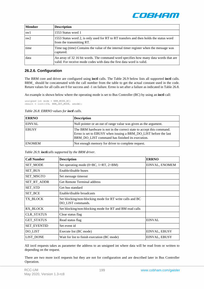
RCC-UMMay 2020, Version 1.3-rc8
199 www.cobham.com/gaisler
Member Description
sw1 1553 Status word 1
sw2 1553 Status word 2, is only used for RT to RT transfers and then holds the status wordfrom the transmitting RT.
time Time tag (time) Contains the value of the internal timer register when the message wascaptured.
data An array of 32 16 bit words. The command word specifies how many data words that arevalid. For receive mode codes with data the first data word is valid.
26.2.6. Configuration
The BRM core and driver are configured using ioctl calls. The Table 26.9 below lists all supported ioctl calls.BRM_ should be concatenated with the call number from the table to get the actual constant used in the code.Return values for all calls are 0 for success and -1 on failure. Errno is set after a failure as indicated in Table 26.8.
An example is shown below where the operating mode is set to Bus Controller (BC) by using an ioctl call:
unsigned int mode = BRM_MODE_BC;result = ioctl(fd, BRM_SET_MODE, &mode);
Table 26.8. ERRNO values for ioctl calls.
ERRNO Description
EINVAL Null pointer or an out of range value was given as the argument.
EBUSY The BRM hardware is not in the correct state to accept this command.Errno is set to EBUSY when issuing a BRM_DO_LIST before the lastBRM_DO_LIST command has finished its execution.
ENOMEM Not enough memory for driver to complete request.
Table 26.9. ioctlcalls supported by the BRM driver.
Call Number Description ERRNO
SET_MODE Set operating mode (0=BC, 1=RT, 2=BM) EINVAL, ENOMEM
SET_BUS Enable/disable buses
SET_MSGTO Set message timeout
SET_RT_ADDR Get Remote Terminal address
SET_STD Get bus standard
SET_BCE Enable/disable broadcasts
TX_BLOCK Set blocking/non-blocking mode for RT write calls and BCDO_LIST commands.
RX_BLOCK Set blocking/non-blocking mode for RT and BM read calls
CLR_STATUS Clear status flag
GET_STATUS Read status flag EINVAL
SET_EVENTID Set event id
DO_LIST Execute list (BC mode) EINVAL, EBUSY
LIST_DONE Wait for list to finish execution (BC mode) EINVAL, EBUSY
All ioctl requests takes as parameter the address to an unsigned int where data will be read from or written todepending on the request.
There are two more ioctl requests but they are not for configuration and are described later in Bus ControllerOperation.
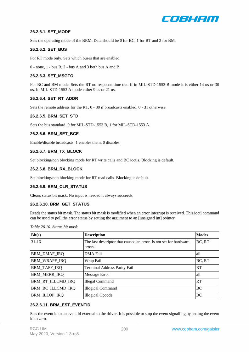
RCC-UMMay 2020, Version 1.3-rc8
200 www.cobham.com/gaisler
26.2.6.1. SET_MODE
Sets the operating mode of the BRM. Data should be 0 for BC, 1 for RT and 2 for BM.
26.2.6.2. SET_BUS
For RT mode only. Sets which buses that are enabled.
0 - none, 1 - bus B, 2 - bus A and 3 both bus A and B.
26.2.6.3. SET_MSGTO
For BC and BM mode. Sets the RT no response time out. If in MIL-STD-1553 B mode it is either 14 us or 30us. In MIL-STD-1553 A mode either 9 us or 21 us.
26.2.6.4. SET_RT_ADDR
Sets the remote address for the RT. 0 - 30 if broadcasts enabled, 0 - 31 otherwise.
26.2.6.5. BRM_SET_STD
Sets the bus standard. 0 for MIL-STD-1553 B, 1 for MIL-STD-1553 A.
26.2.6.6. BRM_SET_BCE
Enable/disable broadcasts. 1 enables them, 0 disables.
26.2.6.7. BRM_TX_BLOCK
Set blocking/non blocking mode for RT write calls and BC ioctls. Blocking is default.
26.2.6.8. BRM_RX_BLOCK
Set blocking/non blocking mode for RT read calls. Blocking is default.
26.2.6.9. BRM_CLR_STATUS
Clears status bit mask. No input is needed it always succeeds.
26.2.6.10. BRM_GET_STATUS
Reads the status bit mask. The status bit mask is modified when an error interrupt is received. This ioctl commandcan be used to poll the error status by setting the argument to an [unsigned int] pointer.
Table 26.10. Status bit mask
Bit(s) Description Modes
31-16 The last descriptor that caused an error. Is not set for hardwareerrors.
BC, RT
BRM_DMAF_IRQ DMA Fail all
BRM_WRAPF_IRQ Wrap Fail BC, RT
BRM_TAPF_IRQ Terminal Address Parity Fail RT
BRM_MERR_IRQ Message Error all
BRM_RT_ILLCMD_IRQ Illegal Command RT
BRM_BC_ILLCMD_IRQ Illogical Command BC
BRM_ILLOP_IRQ Illogical Opcode BC
26.2.6.11. BRM_EST_EVENTID
Sets the event id to an event id external to the driver. It is possible to stop the event signalling by setting the eventid to zero.
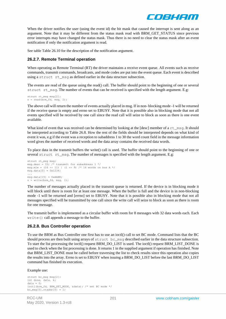
RCC-UMMay 2020, Version 1.3-rc8
201 www.cobham.com/gaisler
When the driver notifies the user (using the event id) the bit mask that caused the interrupt is sent along as anargument. Note that it may be different from the status mask read with BRM_GET_STATUS since previouserror interrupts may have changed the status mask. Thus there is no need to clear the status mask after an eventnotification if only the notification argument is read.
See table Table 26.10 for the description of the notification argument.
26.2.7. Remote Terminal operation
When operating as Remote Terminal (RT) the driver maintains a receive event queue. All events such as receivecommands, transmit commands, broadcasts, and mode codes are put into the event queue. Each event is describedusing a struct rt_msg as defined earlier in the data structure subsection.
The events are read of the queue using the read() call. The buffer should point to the beginning of one or severalstruct rt_msg. The number of events that can be received is specified with the length argument. E.g:
struct rt_msg msg[2];n = read(brm_fd, msg, 2);
The above call will return the number of events actually placed in msg. If in non- blocking mode -1 will be returnedif the receive queue is empty and errno set to EBUSY. Note that it is possible also in blocking mode that not allevents specified will be received by one call since the read call will seize to block as soon as there is one eventavailable.
What kind of event that was received can be determined by looking at the [desc] member of a rt_msg. It shouldbe interpreted according to Table 26.8. How the rest of the fields should be interpreted depends on what kind ofevent it was, e.g if the event was a reception to subaddress 1 to 30 the word count field in the message informationword gives the number of received words and the data array contains the received data words.
To place data in the transmit buffers the write() call is used. The buffer should point to the beginning of one orseveral struct rt_msg. The number of messages is specified with the length argument. E.g:
struct rt_msg msg;msg.desc = 33; /* transmit for subaddress 1 */msg.miw = (16 << 11) | (1 << 9) /* 16 words on bus A */msg.data[0] = 0x1234;...msg.data[15] = 0xAABB;n = write(brm_fd, msg, 1);
The number of messages actually placed in the transmit queue is returned. If the device is in blocking mode itwill block until there is room for at least one message. When the buffer is full and the device is in non-blockingmode -1 will be returned and [errno] set to EBUSY. Note that it is possible also in blocking mode that not allmessages specified will be transmitted by one call since the write call will seize to block as soon as there is roomfor one message.
The transmit buffer is implemented as a circular buffer with room for 8 messages with 32 data words each. Eachwrite() call appends a message to the buffer.
26.2.8. Bus Controller operation
To use the BRM as Bus Controller one first has to use an ioctl() call to set BC mode. Command lists that the BCshould process are then built using arrays of struct bc_msg described earlier in the data structure subsection.To start the list processing the ioctl() request BRM_DO_LIST is used. The ioctl() request BRM_LIST_DONE isused to check when the list processing is done. It returns 1 in the supplied argument if operation has finished. Notethat BRM_LIST_DONE must be called before traversing the list to check results since this operation also copiesthe results into the array. Errno is set to EBUSY when issuing a BRM_DO_LIST before the last BRM_DO_LISTcommand has finished its execution.
Example use:
struct bc_msg msg[2];int done, data, k;data = 0;ioctl(brm_fd, BRM_SET_MODE, &data); /* set BC mode */bc_msg[0].rtaddr[0] = 1;
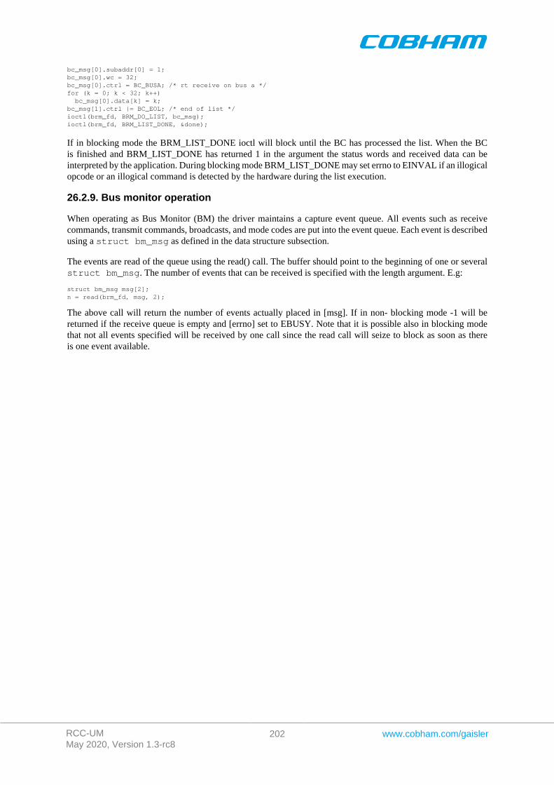
RCC-UMMay 2020, Version 1.3-rc8
202 www.cobham.com/gaisler
bc_msg[0].subaddr[0] = 1;bc_msg[0].wc = 32;bc_msg[0].ctrl = BC_BUSA; /* rt receive on bus a */for (k = 0; k < 32; k++) bc_msg[0].data[k] = k;bc_msg[1].ctrl |= BC_EOL; /* end of list */ioctl(brm_fd, BRM_DO_LIST, bc_msg);ioctl(brm_fd, BRM_LIST_DONE, &done);
If in blocking mode the BRM_LIST_DONE ioctl will block until the BC has processed the list. When the BCis finished and BRM_LIST_DONE has returned 1 in the argument the status words and received data can beinterpreted by the application. During blocking mode BRM_LIST_DONE may set errno to EINVAL if an illogicalopcode or an illogical command is detected by the hardware during the list execution.
26.2.9. Bus monitor operation
When operating as Bus Monitor (BM) the driver maintains a capture event queue. All events such as receivecommands, transmit commands, broadcasts, and mode codes are put into the event queue. Each event is describedusing a struct bm_msg as defined in the data structure subsection.
The events are read of the queue using the read() call. The buffer should point to the beginning of one or severalstruct bm_msg. The number of events that can be received is specified with the length argument. E.g:
struct bm_msg msg[2];n = read(brm_fd, msg, 2);
The above call will return the number of events actually placed in [msg]. If in non- blocking mode -1 will bereturned if the receive queue is empty and [errno] set to EBUSY. Note that it is possible also in blocking modethat not all events specified will be received by one call since the read call will seize to block as soon as thereis one event available.
RCC-UMMay 2020, Version 1.3-rc8
203 www.cobham.com/gaisler
Chapter 27. B1553RT GRLIB Actel Core1553 RT driver
27.1. Introduction
This section describes the B1553RT Remote Terminal driver available for RTEMS. The reader is assumed to bewell acquainted with MIL-STD-1553 and RTEMS.
The B1553RT driver require the RTEMS Driver Manager.
27.1.1. RT Hardware
The B1553RT core operate at the same frequency as the bus, it must be 12, 16, 20 or 24MHz. It requires a 4KByteDMA buffer area that must be aligned properly.
27.1.2. 1.1.2 Examples
There is a simple example available, it illustrates how to set up RT for reception and transmission of messagessent by a BC. Received messages are handled by updating the transmission DMA Area for respective sub address.The example collects statistics for received mode codes that the BC can read at sub address 30.
The example is part of the Gaisler RTEMS distribution, it can be found under /opt/rtems-5/src/sam-ples/rtems-b1553rt.c.
27.2. User interface
The RTEMS MIL-STD-1553B RT driver supports standard accesses to file descriptors such as read, write andioctl. User applications include the rt driver's header file which contains definitions of all necessary data structuresand bit masks used when accessing the driver. An example application using the driver is provided in the examplesdirectory.
27.2.1. Driver registration
The registration of the driver is crucial for threads and processes to be able to access the driver using standardmeans, such as open. The RTEMS I/O driver registration is performed automatically by the driver when B1553RThardware is found for the first time. The driver is called from the driver manager to handle detected B1553RThardware. In order for the driver manager to unite the B1553RT driver with the B1553RT hardware one mustregister the driver to the driver manager. This process is described in the driver manager chapter.
27.2.2. Driver resource configuration
The driver can be configured using driver resources as described in the driver manager chapter. Below is a de-scription of configurable driver parameters. The driver parameters is unique per B1553RT device. The parametersare all optional, the parameters only overrides the default values.
Table 27.1. B1553RT driver parameter description
Name Type Parameter description
coreFreq INT The input clock frequency to the RT core. 0 = 12MHz, 1 = 16MHz, 2= 20MHz,3 = 24MHz. The default is 24MHz. The driver auto detect the bus frequency andoverride the default if the bus frequency is 20MHz, 16MHz or 12MHz. This pa-rameter override the default and the auto detected value.
dmaBaseAdr INT Custom DMA area address. See note below.
27.2.2.1. Custom DMA area parameter
The DMA area can be configured to be located at a custom address. The standard configuration is to leave it upto the driver to do dynamic allocation of the areas. However in some cases it may be required to locate the DMAarea on a custom location, the driver will not allocate memory but will assume that enough memory is availableand that the alignment needs of the core on the address given is fulfilled. The memory required is either 4K bytes.
RCC-UMMay 2020, Version 1.3-rc8
204 www.cobham.com/gaisler
For some systems it may be convenient to give the addresses as seen by the B1553RT core. This can be done bysetting the LSB bit in the address to one. For example a PCI Target board with a AMBA bus with a B1553RTcore doesn't read from the same address as the CPU in order to access the same data. This is dependent on the PCImappings. Translation between CPU and B1553RT addresses must be done. The B1553RT driver automaticallytranslates the DMA base address. This requires the bus driver, in this case the PCI Target driver, to set up translationaddresses correctly.
27.2.3. Opening the device
Opening the device enables the user to access the hardware of a certain RT device. The driver is used for all RTdevices available. The devices is separated by assigning each device a unique name and a number called [minor].The name is passed during the opening of the driver. Some example device names are printed out below.
Table 27.2. Device number to device name conversion.
Device number Filesystem name Location
0 /dev/b1553rt0 On-Chip Bus
1 /dev/b1553rt1 On-Chip Bus
2 /dev/b1553rt2 On-Chip Bus
An example of an RTEMS open call is shown below.
fd = open("/dev/b1553rt0", O_RDWR)
A file descriptor is returned on success and -1 otherwise. In the latter case errno is set as indicated in Table 27.3.
Table 27.3. Open[errno] values.
Errno Description
ENODEV Illegal device name or not available
EBUSY Device already opened
27.2.4. Closing the device
The device is closed using the close call. An example is shown below.
res = close(fd)
Close always returns 0 (success) for the rt driver.
27.2.5. I/O Control interface
Changing the behaviour of the driver for a device is done via the standard system call ioctl. Most operating systemssupport at least two arguments to ioctl, the first being an integer which selects ioctl function and secondly a pointerto data that may be interpreted uniquely for each function. A typical ioctl call definition:
int ioctl(int fd, int cmd, void *arg);
The return value is 0 on success and -1 on failure and the global [errno] variable is set accordingly.
All supported commands and their data structures are defined in the RT driver's header file b1553rt.h.
27.2.5.1. Data structures
27.2.5.1.1. Remote Terminal operating mode
The structure below is used for all received events as well as to put data in the transmit buffer.
struct rt_msg { unsigned short miw; unsigned short time; unsigned short data[32];
RCC-UMMay 2020, Version 1.3-rc8
205 www.cobham.com/gaisler
unsigned short desc;};
Table 27.4. [rt_msg] member descriptions.
Member Description
miw Message Information Word.
Bit(s) Description
15-11 Word count / mode code - For sub addresses this is the number of received words.For mode codes it is the receive/transmit mode code.
10 -
9 A/B - 1 if message receive on bus A, 0 if received on bus B.
8 reserved
7 ME - 1 if an error was encountered during message processing. Bit 4-0 gives thedetails of the error.
6-5 -
4 ILL - 1 if received command is illegalized.
3 reserved
2 reserved
1 PRTY - 1 if the RT detected a parity error in the received data.
0 MAN - 1 if a Manchester decoding error was detected during data reception.
time Time Tag - Contains the value of the internal timer register when the message was received.
data An array of 32 16 bit words. The word count specifies how many data words that are valid. Forreceive mode codes with data the first data word is valid.
desc Bit 6-0 is the descriptor used. Bit 15 indicates software buffer overrun when set, the messageswas not read out in time which lead to the driver needed to skip at least one received message.
The last variable in the struct rt_msg shows which descriptor (i.e rx subaddress, tx subaddress, rx mode code ortx mode code) that the message was for. They are defined as shown in the table below:
Table 27.5. Descriptor table
Descriptor Description
0 Reserved for RX mode codes
1-30 Receive subaddress 1-30
31 Reserved for RX mode codes
32 Reserved for TX mode codes
33-62 Transmit subaddress 1-30
63 Reserved for TX mode codes
64-95 Receive mode code
96-127 Transmit mode code
If there has occurred an event queue overrun bit 15 of this variable will be set in the first event read out. All eventsreceived when the queue is full are lost.
The RT core and driver are configured using ioctl calls. The table Table 27.7 below lists all supported ioctl calls.RT_ should be concatenated with the call number from the table to get the actual constant used in the code. Returnvalues for all calls are 0 for success and -1 on failure. Errno is set after a failure as indicated in Table 27.6.
An example is shown below where the Remote Terminal Address is set to one by using an ioctl call:
RCC-UMMay 2020, Version 1.3-rc8
206 www.cobham.com/gaisler
Table 27.6. ERRNO values for ioctl calls.
ERRNO Description
EINVAL Null pointer or an out of range value was given as the argument.
ENOSYS Invalid request, now such ioctl command.
Table 27.7. ERRNO values for ioctl calls.
Call Number Description ERRNO
SET_ADDR Set Remote Terminal address
SET_BCE Enable/disable broadcast
SET_VECTORW Set VECTOR WORD register in RT core
SET_EXTMDATA Set/Clear EXTMDATA bit in RT core
RX_BLOCK Set blocking/non-blocking mode for read calls
CLR_STATUS Reset status flag
GET_STATUS Read status flag EINVAL
SET_EVENTID Set event id used to signal detected errors with
All ioctl requests takes as parameter the address to [an unsigned int] where data will be read from or written todepending on the request.
27.2.6.1. RT_SET_ADDR
Sets the remote address for the RT. 0 - 30 if broadcasts enabled, 0 - 31 otherwise.
27.2.6.2. RT_SET_BCE
Enable/disable broadcasts. 1 enables them, 0 disables.
27.2.6.3. RT_SET_VECTORW
Set the vector word register in the RT core. This might not have an effect depending on how the RT core registerhave been set up.
27.2.6.4. RT_RX_BLOCK
Set blocking/non blocking mode for RT read calls. Blocking is default.
27.2.6.5. RT_SET_EXTMDATA
Set or clear the EXTMDATA bit of the RT core. The input is a pointer to a integer which determines the EXTM-DATA bit.
27.2.6.6. RT_SET_STATUS
Clears status bit mask. No input is needed it always succeeds.
27.2.6.7. RT_GET_STATUS
Reads the status bit mask. The status bit mask is modified when an error interrupt is received. This ioctl commandcan be used to poll the error status by setting the argument to an unsigned int pointer.
Table 27.8. Status bit mask
Bit(s) Description
31-16 The last descriptor that caused an error. Is not set for hardware errors.
RT_DMAF_IRQ DMA Fail, AHB error from AMBA wrapper or Memory failure indicated by the RTCore.
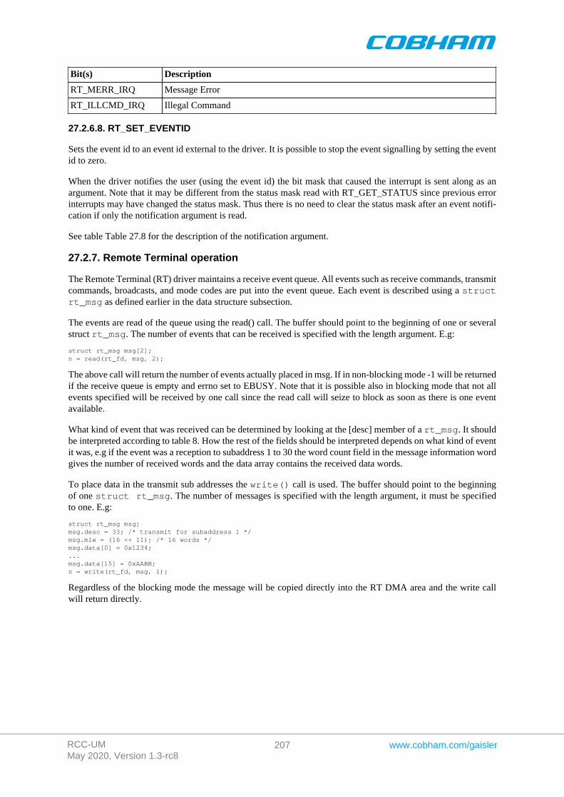
RCC-UMMay 2020, Version 1.3-rc8
207 www.cobham.com/gaisler
Bit(s) Description
RT_MERR_IRQ Message Error
RT_ILLCMD_IRQ Illegal Command
27.2.6.8. RT_SET_EVENTID
Sets the event id to an event id external to the driver. It is possible to stop the event signalling by setting the eventid to zero.
When the driver notifies the user (using the event id) the bit mask that caused the interrupt is sent along as anargument. Note that it may be different from the status mask read with RT_GET_STATUS since previous errorinterrupts may have changed the status mask. Thus there is no need to clear the status mask after an event notifi-cation if only the notification argument is read.
See table Table 27.8 for the description of the notification argument.
27.2.7. Remote Terminal operation
The Remote Terminal (RT) driver maintains a receive event queue. All events such as receive commands, transmitcommands, broadcasts, and mode codes are put into the event queue. Each event is described using a structrt_msg as defined earlier in the data structure subsection.
The events are read of the queue using the read() call. The buffer should point to the beginning of one or severalstruct rt_msg. The number of events that can be received is specified with the length argument. E.g:
struct rt_msg msg[2];n = read(rt_fd, msg, 2);
The above call will return the number of events actually placed in msg. If in non-blocking mode -1 will be returnedif the receive queue is empty and errno set to EBUSY. Note that it is possible also in blocking mode that not allevents specified will be received by one call since the read call will seize to block as soon as there is one eventavailable.
What kind of event that was received can be determined by looking at the [desc] member of a rt_msg. It shouldbe interpreted according to table 8. How the rest of the fields should be interpreted depends on what kind of eventit was, e.g if the event was a reception to subaddress 1 to 30 the word count field in the message information wordgives the number of received words and the data array contains the received data words.
To place data in the transmit sub addresses the write() call is used. The buffer should point to the beginningof one struct rt_msg. The number of messages is specified with the length argument, it must be specifiedto one. E.g:
struct rt_msg msg;msg.desc = 33; /* transmit for subaddress 1 */msg.miw = (16 << 11); /* 16 words */msg.data[0] = 0x1234;...msg.data[15] = 0xAABB;n = write(rt_fd, msg, 1);
Regardless of the blocking mode the message will be copied directly into the RT DMA area and the write callwill return directly.
RCC-UMMay 2020, Version 1.3-rc8
208 www.cobham.com/gaisler
Chapter 28. GRCAN CAN driver
28.1. Introduction
The RTEMS GRCAN driver is accessed with a function based interface defined by the header file grcan.h andthis document.
The GRCAN driver requires the RTEMS Driver Manager.
28.1.1. Driver registration
The registration of the driver is crucial for threads and processes to be able to access the driver. The driver iscalled from the driver manager to handle detected GRCAN hardware. In order for the driver manager to unite theGRCAN driver with the GRCAN hardware one must register the driver to the driver manager. This process isdescribed in the driver manager chapter.
28.1.2. Driver resource configuration
The driver can be configured using driver resources as described in the driver manager chapter. Below is a de-scription of configurable driver parameters. The driver parameters are unique to a CAN device. Each parametersis optional and overrides the default value.
Table 28.1. GRCAN driver parameter description
Name Type Parameter description
txBufSize INT Length of TX DMA area. Must be a multiple of 64 bytes, four messages.
rxBufSize INT Length of RX DMA area. Must be a multiple of 64 bytes, four messages.
txBufAdr INT Custom TX DMA area address. See note below.
rxBufAdr INT Custom RX DMA area address. See note below.
28.1.2.1. Custom DMA area parameters
The DMA area can be configured to be located at a custom address. The standard configuration is to leave it upto the driver to do dynamic allocation of the areas. However in some cases it may be required to locate the DMAarea on a custom location, the driver will not allocate memory but will assume that enough memory is availableand that the alignment needs of the core on the address given is fulfilled.
For some systems it may be convenient to give the addresses as seen by the CAN core. This can be done by settingthe LSB bit in the address to one. For example a GR- RASTA-IO board with a CAN core doesn't read from thesame address as the CPU in order to access the same data. This is dependent on the PCI mappings. Translationbetween CPU and CAN addresses must be done. The CAN driver automatically translates the required addresses.This requires the bus driver, in this case the GR-RASTA-IO driver, to set up translation addresses correctly.
28.2. User Interface
This section covers how the driver can be interfaced to an application to control the GRCAN hardware.
Controlling the driver and device is done with functions provided by the driver prefixed with grcan_. All driverfunctions take a device handle returned by grcan_open as the first parameter. All supported commands andtheir data structures are defined in the CAN driver's header file grcan.h.
28.2.1. Opening and closing device
A GRCAN device must first be opened before any operations can be performed using the driver. The number ofdevices registered to the driver can be retrieved using grcan_dev_count. A particular device can be opened byindex using grcan_open, opened by name using grcan_open_by_name and closed using grcan_close.The functions are described below.
RCC-UMMay 2020, Version 1.3-rc8
209 www.cobham.com/gaisler
An opened device can not be reopened unless the device is closed first. When opening a device the device ismarked opened by the driver. This procedure is thread-safe by protecting from other threads by using the GRCANdriver's semaphore lock. The semaphore is used by all GRCAN devices on device opening and closing.
The example below prints the number of GRCAN devices to screen then opens and closes the first GRCAN devicepresent in the system.
int print_grcan_devices(){ void *device; int count, options, clkdiv;
count = grcan_dev_count(); printf("%d GRCAN device(s) present\n", count);
device = grcan_open(0); if (!device) return -1; /* Failure */
grcan_close(device); return 0; /* success */}
Table 28.2. grcan_dev_count function declaration
Proto int grcan_dev_count(void)
About Retrieve number of GRCAN devices registered to the driver.
Return int. Number of GRCAN devices registered in system, zero if none.
Table 28.3. grcan_open function declaration
Proto void *grcan_open(int dev_no)
About Opens a GRCAN device. The GRCAN device is identified by index. The returned value is used as in-put argument to all functions operating on the device.
dev_no [IN] IntegerParam
Device identification number. Devices are indexed by the registration order to the driver, normallydictated by the Plug & Play order. Must be equal or greater than zero, and smaller than that returnedby grcan_dev_count.
Pointer. Status and driver's internal device identification.
NULL Indicates failure to open device. Fails if device semaphore fails or device already isopen.
Return
Pointer Pointer to internal driver structure. Should not be dereferenced by user. Input to all de-vice API functions, identifies which GRCAN device.
Notes May blocking until other GRCAN device operations complete.
Table 28.4. grcan_open_by_name function declaration
Proto void *grcan_open_by_name(char *name, int *dev_no)
About Opens a GRCAN device. The GRCAN device is identified by a string. This function finds the deviceindex and then calls grcan_open(index). The returned value is used as input argument to allfunctions operating on the device.
name [IN] PointerParam
Device name to open. For example grcan0.
dev_no [OUT] PointerParam
Device number matching name. Will be set if device is found and dev_no != NULL.
Pointer. Status and driver's internal device identification.Return
NULL Indicates failure to open device. Fails if device semaphore fails or device already isopen.
RCC-UMMay 2020, Version 1.3-rc8
210 www.cobham.com/gaisler
Pointer Pointer to internal driver structure. Should not be dereferenced by user. Input to all de-vice API functions, identifies which GRCAN device.
Notes May blocking until other GRCAN device operations complete.
Table 28.5. grcan_close function declaration
Proto int grcan_close(void *d)
About Closes a previously opened device.
d [IN] pointerParam
Device identifier. Returned from grcan_open.
Return int. This function always returns 0 (success)
28.2.2. Operation mode
The driver always operates in one of four modes: STATE_STARTED, STATE_STOPPED, STATE_BUSOFF orSTATE_AHBERR. In STATE_STOPPED mode, the DMA is disabled and the user is allowed to configure thedevice and driver. In STATE_STARTED mode, the receive and transmit DMA can be active and only a limitednumber of configuration operations are possible.
The driver enters STATE_BUSOFF mode if a bus-off condition is detected and STATE_AHBERR if an AHB erroris caused by the GRCAN DMA. When any of these two modes are entered, the user should call grcan_stop()followd by grcan_start() to put the driver in STATE_STARTED again.
Transitions between started and stopped mode are normally caused by the users interaction with the driver APIfunctions. In some situations, such CAN bus-off or DMA AHB error condition, the driver itself makes the transitionfrom started to stopped.
28.2.2.1. Starting and stopping
The grcan_start() function places the CAN core in STATE_STARTED mode. Configuration set by previousdriver function calls are committed to hardware before started mode enters. It is necessary to enter started mode tobe able to receive and transmit messages on the CAN bus. The grcan_start() function call will fail if receiveor transmit buffers are not correctly allocated or if the CAN core is already is in started mode.
The function grcan_stop() makes the CAN core leave the previous mode and enter STATE_STOPPED mode.After calling this function, further calls to grcan_read() or grcan_write() will fail. It is necessary toenter stopped mode to change operating parameters of the CAN core such as the baud rate and for the driverto safely change configuration such as FIFO buffer lengths. The function will fail if the CAN core already is instopped mode.
Function grcan_get_state() is used to determine the driver operation mode.
Table 28.6. grcan_get_state function declaration
Proto int grcan_get_state(void *d)
About Get current GRCAN software state
If STATE_BUSOFF or STATE_AHBERR is returned then the function grcan_stop() shall becalled before continue using the driver.
d [IN] PointerParam
Device identifier. Returned by grcan_open.
int. Status
Value Description
STATE_STOPPED Stopped
Return
STATE_STARTED Started
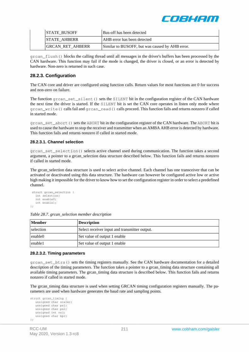
RCC-UMMay 2020, Version 1.3-rc8
211 www.cobham.com/gaisler
STATE_BUSOFF Bus-off has been detected
STATE_AHBERR AHB error has been detected
GRCAN_RET_AHBERR Similar to BUSOFF, but was caused by AHB error.
grcan_flush() blocks the calling thread until all messages in the driver's buffers has been processed by theCAN hardware. This function may fail if the mode is changed, the driver is closed, or an error is detected byhardware. Non-zero is returned in such case.
28.2.3. Configuration
The CAN core and driver are configured using function calls. Return values for most functions are 0 for successand non-zero on failure.
The function grcan_set_silent() sets the SILENT bit in the configuration register of the CAN hardwarethe next time the driver is started. If the SILENT bit is set the CAN core operates in listen only mode wheregrcan_write() calls fail and grcan_read() calls proceed. This function fails and returns nonzero if calledin started mode.
grcan_set_abort() sets the ABORT bit in the configuration register of the CAN hardware. The ABORT bit isused to cause the hardware to stop the receiver and transmitter when an AMBA AHB error is detected by hardware.This function fails and returns nonzero if called in started mode.
28.2.3.1. Channel selection
grcan_set_selection() selects active channel used during communication. The function takes a secondargument, a pointer to a grcan_selection data structure described below. This function fails and returns nonzeroif called in started mode.
The grcan_selection data structure is used to select active channel. Each channel has one transceiver that can beactivated or deactivated using this data structure. The hardware can however be configured active low or activehigh making it impossible for the driver to know how to set the configuration register in order to select a predefinedchannel.
struct grcan_selection { int selection; int enable0; int enable1;};
Table 28.7. grcan_selection member description
Member Description
selection Select receiver input and transmitter output.
enable0 Set value of output 1 enable
enable1 Set value of output 1 enable
28.2.3.2. Timing parameters
grcan_set_btrs() sets the timing registers manually. See the CAN hardware documentation for a detaileddescription of the timing parameters. The function takes a pointer to a grcan_timing data structure containing allavailable timing parameters. The grcan_timing data structure is described below. This function fails and returnsnonzero if called in started mode.
The grcan_timing data structure is used when setting GRCAN timing configuration registers manually. The pa-rameters are used when hardware generates the baud rate and sampling points.
struct grcan_timing { unsigned char scaler; unsigned char ps1; unsigned char ps2; unsigned int rsj; unsigned char bpr;};
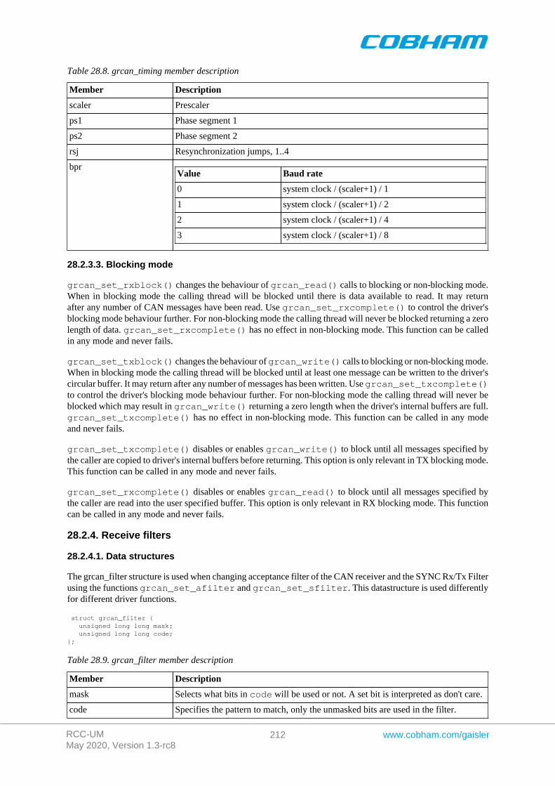
RCC-UMMay 2020, Version 1.3-rc8
212 www.cobham.com/gaisler
Table 28.8. grcan_timing member description
Member Description
scaler Prescaler
ps1 Phase segment 1
ps2 Phase segment 2
rsj Resynchronization jumps, 1..4
bprValue Baud rate
0 system clock / (scaler+1) / 1
1 system clock / (scaler+1) / 2
2 system clock / (scaler+1) / 4
3 system clock / (scaler+1) / 8
28.2.3.3. Blocking mode
grcan_set_rxblock() changes the behaviour of grcan_read() calls to blocking or non-blocking mode.When in blocking mode the calling thread will be blocked until there is data available to read. It may returnafter any number of CAN messages have been read. Use grcan_set_rxcomplete() to control the driver'sblocking mode behaviour further. For non-blocking mode the calling thread will never be blocked returning a zerolength of data. grcan_set_rxcomplete() has no effect in non-blocking mode. This function can be calledin any mode and never fails.
grcan_set_txblock() changes the behaviour of grcan_write() calls to blocking or non-blocking mode.When in blocking mode the calling thread will be blocked until at least one message can be written to the driver'scircular buffer. It may return after any number of messages has been written. Use grcan_set_txcomplete()to control the driver's blocking mode behaviour further. For non-blocking mode the calling thread will never beblocked which may result in grcan_write() returning a zero length when the driver's internal buffers are full.grcan_set_txcomplete() has no effect in non-blocking mode. This function can be called in any modeand never fails.
grcan_set_txcomplete() disables or enables grcan_write() to block until all messages specified bythe caller are copied to driver's internal buffers before returning. This option is only relevant in TX blocking mode.This function can be called in any mode and never fails.
grcan_set_rxcomplete() disables or enables grcan_read() to block until all messages specified bythe caller are read into the user specified buffer. This option is only relevant in RX blocking mode. This functioncan be called in any mode and never fails.
28.2.4. Receive filters
28.2.4.1. Data structures
The grcan_filter structure is used when changing acceptance filter of the CAN receiver and the SYNC Rx/Tx Filterusing the functions grcan_set_afilter and grcan_set_sfilter. This datastructure is used differentlyfor different driver functions.
struct grcan_filter { unsigned long long mask; unsigned long long code;};
Table 28.9. grcan_filter member description
Member Description
mask Selects what bits in code will be used or not. A set bit is interpreted as don't care.
code Specifies the pattern to match, only the unmasked bits are used in the filter.
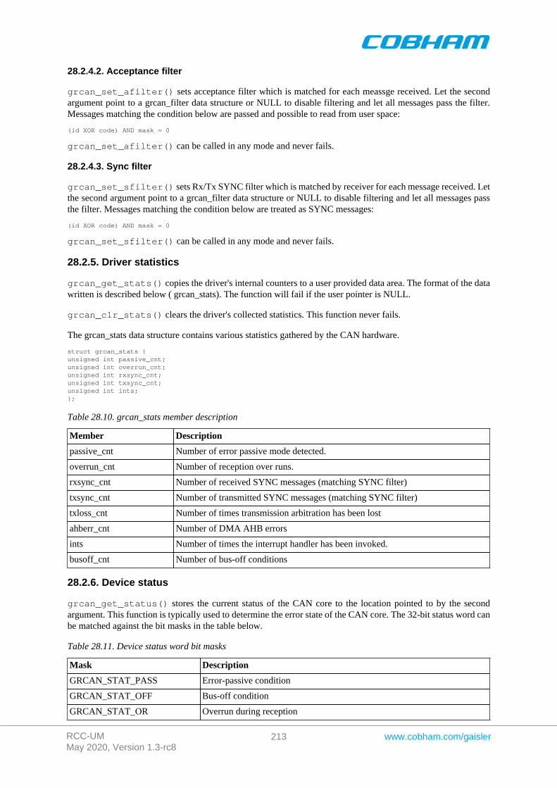
RCC-UMMay 2020, Version 1.3-rc8
213 www.cobham.com/gaisler
28.2.4.2. Acceptance filter
grcan_set_afilter() sets acceptance filter which is matched for each meassge received. Let the secondargument point to a grcan_filter data structure or NULL to disable filtering and let all messages pass the filter.Messages matching the condition below are passed and possible to read from user space:
(id XOR code) AND mask = 0
grcan_set_afilter() can be called in any mode and never fails.
28.2.4.3. Sync filter
grcan_set_sfilter() sets Rx/Tx SYNC filter which is matched by receiver for each message received. Letthe second argument point to a grcan_filter data structure or NULL to disable filtering and let all messages passthe filter. Messages matching the condition below are treated as SYNC messages:
(id XOR code) AND mask = 0
grcan_set_sfilter() can be called in any mode and never fails.
28.2.5. Driver statistics
grcan_get_stats() copies the driver's internal counters to a user provided data area. The format of the datawritten is described below ( grcan_stats). The function will fail if the user pointer is NULL.
grcan_clr_stats() clears the driver's collected statistics. This function never fails.
The grcan_stats data structure contains various statistics gathered by the CAN hardware.
struct grcan_stats {unsigned int passive_cnt;unsigned int overrun_cnt;unsigned int rxsync_cnt;unsigned int txsync_cnt;unsigned int ints;};
Table 28.10. grcan_stats member description
Member Description
passive_cnt Number of error passive mode detected.
overrun_cnt Number of reception over runs.
rxsync_cnt Number of received SYNC messages (matching SYNC filter)
txsync_cnt Number of transmitted SYNC messages (matching SYNC filter)
txloss_cnt Number of times transmission arbitration has been lost
ahberr_cnt Number of DMA AHB errors
ints Number of times the interrupt handler has been invoked.
busoff_cnt Number of bus-off conditions
28.2.6. Device status
grcan_get_status() stores the current status of the CAN core to the location pointed to by the secondargument. This function is typically used to determine the error state of the CAN core. The 32-bit status word canbe matched against the bit masks in the table below.
Table 28.11. Device status word bit masks
Mask Description
GRCAN_STAT_PASS Error-passive condition
GRCAN_STAT_OFF Bus-off condition
GRCAN_STAT_OR Overrun during reception
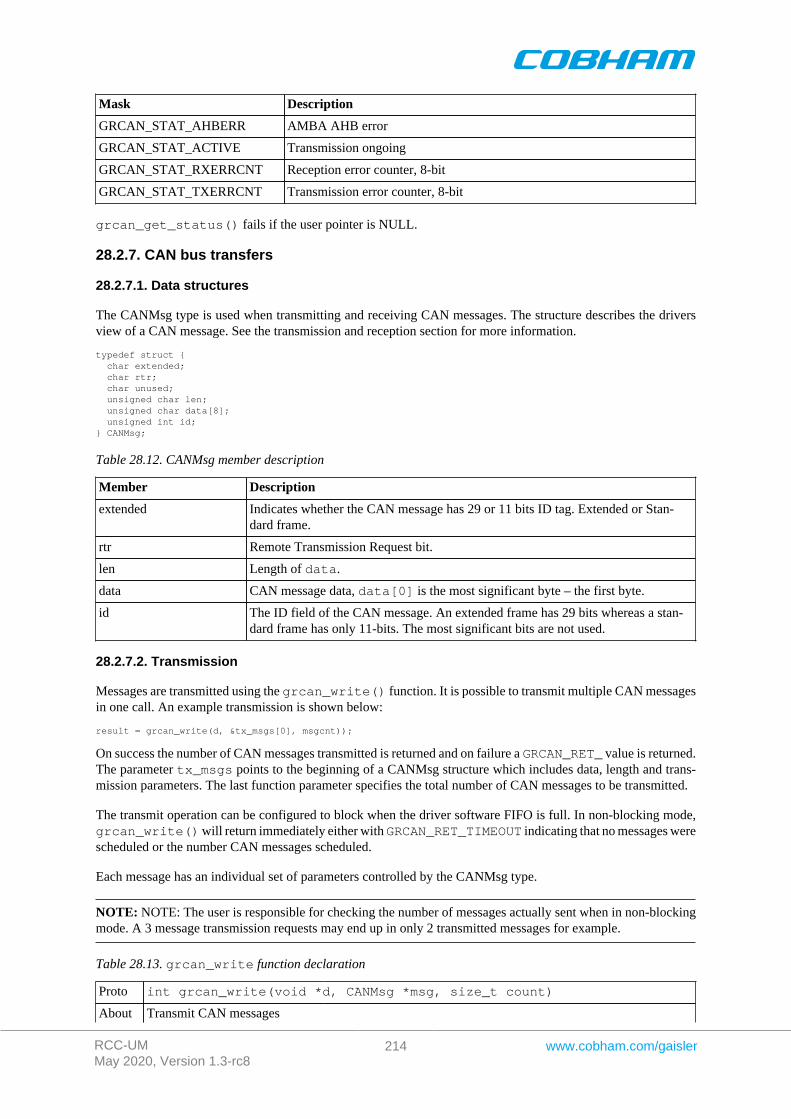
RCC-UMMay 2020, Version 1.3-rc8
214 www.cobham.com/gaisler
Mask Description
GRCAN_STAT_AHBERR AMBA AHB error
GRCAN_STAT_ACTIVE Transmission ongoing
GRCAN_STAT_RXERRCNT Reception error counter, 8-bit
GRCAN_STAT_TXERRCNT Transmission error counter, 8-bit
grcan_get_status() fails if the user pointer is NULL.
28.2.7. CAN bus transfers
28.2.7.1. Data structures
The CANMsg type is used when transmitting and receiving CAN messages. The structure describes the driversview of a CAN message. See the transmission and reception section for more information.
typedef struct { char extended; char rtr; char unused; unsigned char len; unsigned char data[8]; unsigned int id;} CANMsg;
Table 28.12. CANMsg member description
Member Description
extended Indicates whether the CAN message has 29 or 11 bits ID tag. Extended or Stan-dard frame.
rtr Remote Transmission Request bit.
len Length of data.
data CAN message data, data[0] is the most significant byte – the first byte.
id The ID field of the CAN message. An extended frame has 29 bits whereas a stan-dard frame has only 11-bits. The most significant bits are not used.
28.2.7.2. Transmission
Messages are transmitted using the grcan_write() function. It is possible to transmit multiple CAN messagesin one call. An example transmission is shown below:
result = grcan_write(d, &tx_msgs[0], msgcnt));
On success the number of CAN messages transmitted is returned and on failure a GRCAN_RET_ value is returned.The parameter tx_msgs points to the beginning of a CANMsg structure which includes data, length and trans-mission parameters. The last function parameter specifies the total number of CAN messages to be transmitted.
The transmit operation can be configured to block when the driver software FIFO is full. In non-blocking mode,grcan_write() will return immediately either with GRCAN_RET_TIMEOUT indicating that no messages werescheduled or the number CAN messages scheduled.
Each message has an individual set of parameters controlled by the CANMsg type.
NOTE: NOTE: The user is responsible for checking the number of messages actually sent when in non-blockingmode. A 3 message transmission requests may end up in only 2 transmitted messages for example.
Table 28.13. grcan_write function declaration
Proto int grcan_write(void *d, CANMsg *msg, size_t count)
About Transmit CAN messages
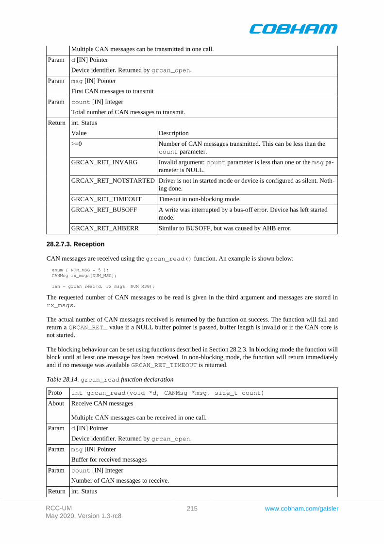
RCC-UMMay 2020, Version 1.3-rc8
215 www.cobham.com/gaisler
Multiple CAN messages can be transmitted in one call.
d [IN] PointerParam
Device identifier. Returned by grcan_open.
msg [IN] PointerParam
First CAN messages to transmit
count [IN] IntegerParam
Total number of CAN messages to transmit.
int. Status
Value Description
>=0 Number of CAN messages transmitted. This can be less than thecount parameter.
GRCAN_RET_INVARG Invalid argument: count parameter is less than one or the msg pa-rameter is NULL.
GRCAN_RET_NOTSTARTED Driver is not in started mode or device is configured as silent. Noth-ing done.
GRCAN_RET_TIMEOUT Timeout in non-blocking mode.
GRCAN_RET_BUSOFF A write was interrupted by a bus-off error. Device has left startedmode.
Return
GRCAN_RET_AHBERR Similar to BUSOFF, but was caused by AHB error.
28.2.7.3. Reception
CAN messages are received using the grcan_read() function. An example is shown below:
enum { NUM_MSG = 5 }; CANMsg rx_msgs[NUM_MSG];
len = grcan_read(d, rx_msgs, NUM_MSG);
The requested number of CAN messages to be read is given in the third argument and messages are stored inrx_msgs.
The actual number of CAN messages received is returned by the function on success. The function will fail andreturn a GRCAN_RET_ value if a NULL buffer pointer is passed, buffer length is invalid or if the CAN core isnot started.
The blocking behaviour can be set using functions described in Section 28.2.3. In blocking mode the function willblock until at least one message has been received. In non-blocking mode, the function will return immediatelyand if no message was available GRCAN_RET_TIMEOUT is returned.
Table 28.14. grcan_read function declaration
Proto int grcan_read(void *d, CANMsg *msg, size_t count)
About Receive CAN messages
Multiple CAN messages can be received in one call.
d [IN] PointerParam
Device identifier. Returned by grcan_open.
msg [IN] PointerParam
Buffer for received messages
count [IN] IntegerParam
Number of CAN messages to receive.
Return int. Status

RCC-UMMay 2020, Version 1.3-rc8
216 www.cobham.com/gaisler
Value Description
>=0 Number of CAN messages received. This can be less than thecount parameter.
GRCAN_RET_INVARG Invalid argument: count parameter is less than one or the msg pa-rameter is NULL.
GRCAN_RET_NOTSTARTED Driver is not in started mode. Nothing done.
GRCAN_RET_TIMEOUT Timeout in non-blocking mode (no space available in driver receiveFIFO).
GRCAN_RET_BUSOFF A read was interrupted by a bus-off error. Device has left startedmode.
GRCAN_RET_AHBERR Similar to BUSOFF, but was caused by AHB Error.
28.2.7.4. Bus-off recovery
If either grcan_write() or grcan_read() returns GRCAN_RET_BUSOFF, then a bus-off condition wasdetected and the driver has entered STATE_BUSOFF mode. To continue using the drirver, the user shall callgrcan_stop() followed by grcan_start() to enter started mode. It must be ensured that no other task iscalling the driver when recovering with grcan_start().
28.2.7.5. AHB error recovery
Similar to the bus-off condition, an AHB error condition can be caused by the GRCAN DMA. The driver willenter STATE_AHBERR and the recovery procedure is the same as for bus-off.
28.2.8. Multitasking support
The functions grcan_write() and grcan_read() can be called on the same device handle concurrentlyfrom different tasks, potentially executing on different processors in an SMP system.

RCC-UMMay 2020, Version 1.3-rc8
217 www.cobham.com/gaisler
Chapter 29. CAN_OC GRLIB Opencores CAN driver
29.1. Introduction
This document is intended as an aid in getting started developing with GRLIB wrapper for Opencores CAN coreusing the driver described in this document. It briefly takes the reader through some of the most important steps inusing the driver such as setting up a connection, configuring the driver, reading and writing CAN messages. Thereader is assumed to be well acquainted with CAN and RTEMS.
The OC_CAN driver require the RTEMS Driver Manager.
29.1.1. CAN Hardware
The OC_CAN core can operate in different modes providing the same register interfaces as other well knownCAN cores. The OC_CAN driver supports PeliCAN mode only.
29.1.2. Software Driver
The driver provides means for processes and threads to send and receive messages. Errors can be detected bypolling the status flags of the driver. Bus off errors cancels the ongoing transfers to let the caller handle the error.
The driver supports filtering received messages id fields by means of acceptance filters, runtime timing registercalculation given a baud rate. However not all baud rates may be available for a given system frequency. Thesystem frequency is hard coded and must be set in the driver.
29.1.3. Examples
There is a simple example available, it illustrates how to set up a connection, reading and writing messages usingthe OC_CAN driver. It is made up of two tasks communicating with each other through two OC_CAN devices.To be able to run the example one must have two OC_CAN devices externally connected together on the differentor the same board.
The example is part of the Gaisler RTEMS distribution, it can be found under /opt/rtems-5/src/exam-ples/samples/rtems-occan.c, occan_lib.c and occan_lib.h .
The example can be built by running:
cd /opt/rtems-4.10/src/examples/samplesmake clean rtems-occan rtems-occan_tx rtems-occan_rx
Where rtems-occan is intended for boards with two OC_CAN cores and rtems-occan_* is for set ups includingtwo boards with one OC_CAN core each.
29.2. User interface
The RTEMS OC_CAN driver supports the standard accesses to file descriptors such as read, write and ioctl. Userapplications include the occan driver's header file which contains definitions of all necessary data structures andbit masks used when accessing the driver. An example application using the driver is provided in the examplesdirectory.
29.2.1. Driver registration
The registration of the driver is crucial for threads and processes to be able to access the driver using standardmeans, such as open. The RTEMS I/O driver registration is performed automatically by the driver when CANhardware is found for the first time. The driver is called from the driver manager to handle detected CAN hardware.In order for the driver manager to unite the CAN driver with the CAN hardware one must register the driver tothe driver manager. This process is described in the driver manager chapter.
29.2.2. Driver resource configuration
This driver does not have any configurable resources. All configuration can be made though the ioctl interface.
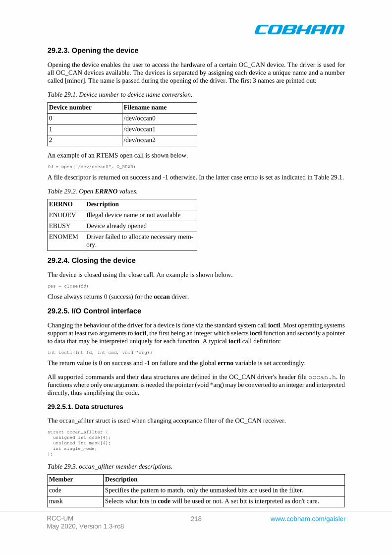
RCC-UMMay 2020, Version 1.3-rc8
218 www.cobham.com/gaisler
29.2.3. Opening the device
Opening the device enables the user to access the hardware of a certain OC_CAN device. The driver is used forall OC_CAN devices available. The devices is separated by assigning each device a unique name and a numbercalled [minor]. The name is passed during the opening of the driver. The first 3 names are printed out:
Table 29.1. Device number to device name conversion.
Device number Filename name
0 /dev/occan0
1 /dev/occan1
2 /dev/occan2
An example of an RTEMS open call is shown below.
fd = open("/dev/occan0", O_RDWR)
A file descriptor is returned on success and -1 otherwise. In the latter case errno is set as indicated in Table 29.1.
Table 29.2. Open ERRNO values.
ERRNO Description
ENODEV Illegal device name or not available
EBUSY Device already opened
ENOMEM Driver failed to allocate necessary mem-ory.
29.2.4. Closing the device
The device is closed using the close call. An example is shown below.
res = close(fd)
Close always returns 0 (success) for the occan driver.
29.2.5. I/O Control interface
Changing the behaviour of the driver for a device is done via the standard system call ioctl. Most operating systemssupport at least two arguments to ioctl, the first being an integer which selects ioctl function and secondly a pointerto data that may be interpreted uniquely for each function. A typical ioctl call definition:
int ioctl(int fd, int cmd, void *arg);
The return value is 0 on success and -1 on failure and the global errno variable is set accordingly.
All supported commands and their data structures are defined in the OC_CAN driver's header file occan.h. Infunctions where only one argument is needed the pointer (void *arg) may be converted to an integer and interpreteddirectly, thus simplifying the code.
29.2.5.1. Data structures
The occan_afilter struct is used when changing acceptance filter of the OC_CAN receiver.
struct occan_afilter { unsigned int code[4]; unsigned int mask[4]; int single_mode;};
Table 29.3. occan_afilter member descriptions.
Member Description
code Specifies the pattern to match, only the unmasked bits are used in the filter.
mask Selects what bits in code will be used or not. A set bit is interpreted as don't care.
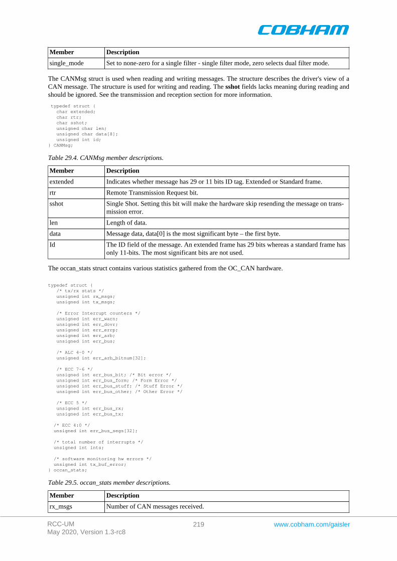
RCC-UMMay 2020, Version 1.3-rc8
219 www.cobham.com/gaisler
Member Description
single_mode Set to none-zero for a single filter - single filter mode, zero selects dual filter mode.
The CANMsg struct is used when reading and writing messages. The structure describes the driver's view of aCAN message. The structure is used for writing and reading. The sshot fields lacks meaning during reading andshould be ignored. See the transmission and reception section for more information.
typedef struct { char extended; char rtr; char sshot; unsigned char len; unsigned char data[8]; unsigned int id;} CANMsg;
Table 29.4. CANMsg member descriptions.
Member Description
extended Indicates whether message has 29 or 11 bits ID tag. Extended or Standard frame.
rtr Remote Transmission Request bit.
sshot Single Shot. Setting this bit will make the hardware skip resending the message on trans-mission error.
len Length of data.
data Message data, data[0] is the most significant byte – the first byte.
Id The ID field of the message. An extended frame has 29 bits whereas a standard frame hasonly 11-bits. The most significant bits are not used.
The occan_stats struct contains various statistics gathered from the OC_CAN hardware.
typedef struct { /* tx/rx stats */ unsigned int rx_msgs; unsigned int tx_msgs;
/* Error Interrupt counters */ unsigned int err_warn; unsigned int err_dovr; unsigned int err_errp; unsigned int err_arb; unsigned int err_bus;
/* ALC 4-0 */ unsigned int err_arb_bitnum[32];
/* ECC 7-6 */ unsigned int err_bus_bit; /* Bit error */ unsigned int err_bus_form; /* Form Error */ unsigned int err_bus_stuff; /* Stuff Error */ unsigned int err_bus_other; /* Other Error */
/* ECC 5 */ unsigned int err_bus_rx; unsigned int err_bus_tx;
/* ECC 4:0 */ unsigned int err_bus_segs[32];
/* total number of interrupts */ unsigned int ints;
/* software monitoring hw errors */ unsigned int tx_buf_error;} occan_stats;
Table 29.5. occan_stats member descriptions.
Member Description
rx_msgs Number of CAN messages received.
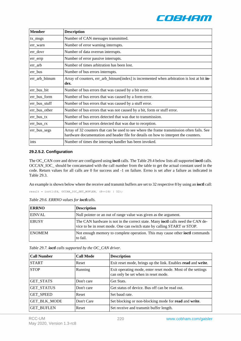
RCC-UMMay 2020, Version 1.3-rc8
220 www.cobham.com/gaisler
Member Description
tx_msgs Number of CAN messages transmitted.
err_warn Number of error warning interrupts.
err_dovr Number of data overrun interrupts.
err_errp Number of error passive interrupts.
err_arb Number of times arbitration has been lost.
err_bus Number of bus errors interrupts.
err_arb_bitnum Array of counters, err_arb_bitnum[index] is incremented when arbitration is lost at bit in-dex.
err_bus_bit Number of bus errors that was caused by a bit error.
err_bus_form Number of bus errors that was caused by a form error.
err_bus_stuff Number of bus errors that was caused by a stuff error.
err_bus_other Number of bus errors that was not caused by a bit, form or stuff error.
err_bus_tx Number of bus errors detected that was due to transmission.
err_bus_rx Number of bus errors detected that was due to reception.
err_bus_segs Array of 32 counters that can be used to see where the frame transmission often fails. Seehardware documentation and header file for details on how to interpret the counters.
ints Number of times the interrupt handler has been invoked.
29.2.5.2. Configuration
The OC_CAN core and driver are configured using ioctl calls. The Table 29.4 below lists all supported ioctl calls.OCCAN_IOC_ should be concatenated with the call number from the table to get the actual constant used in thecode. Return values for all calls are 0 for success and -1 on failure. Errno is set after a failure as indicated inTable 29.3.
An example is shown below where the receive and transmit buffers are set to 32 respective 8 by using an ioctl call:
result = ioctl(fd, OCCAN_IOC_SET_BUFLEN, (8<<16) | 32);
Table 29.6. ERRNO values for ioctlcalls.
ERRNO Description
EINVAL Null pointer or an out of range value was given as the argument.
EBUSY The CAN hardware is not in the correct state. Many ioctl calls need the CAN de-vice to be in reset mode. One can switch state by calling START or STOP.
ENOMEM Not enough memory to complete operation. This may cause other ioctl commandsto fail.
Table 29.7. ioctl calls supported by the OC_CAN driver.
Call Number Call Mode Description
START Reset Exit reset mode, brings up the link. Enables read and write.
STOP Running Exit operating mode, enter reset mode. Most of the settingscan only be set when in reset mode.
GET_STATS Don't care Get Stats.
GET_STATUS Don't care Get status of device. Bus off can be read out.
GET_SPEED Reset Set baud rate.
GET_BLK_MODE Don't Care Set blocking or non-blocking mode for read and write.
GET_BUFLEN Reset Set receive and transmit buffer length.
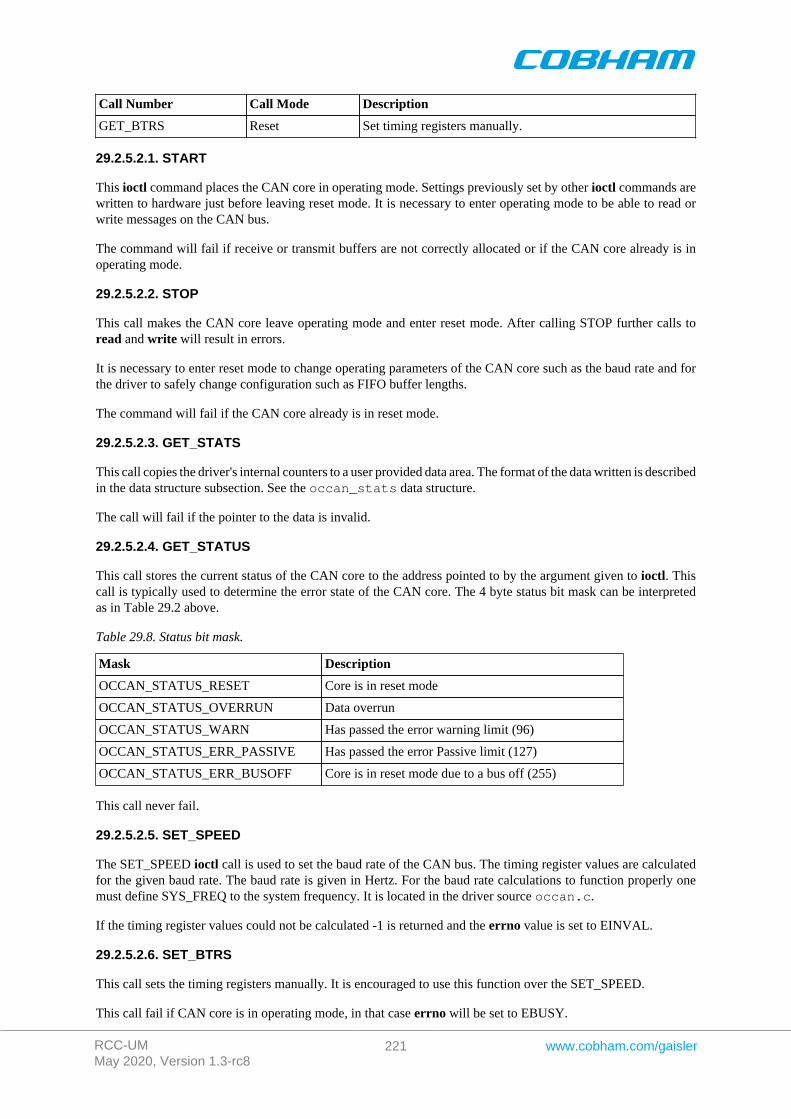
RCC-UMMay 2020, Version 1.3-rc8
221 www.cobham.com/gaisler
Call Number Call Mode Description
GET_BTRS Reset Set timing registers manually.
29.2.5.2.1. START
This ioctl command places the CAN core in operating mode. Settings previously set by other ioctl commands arewritten to hardware just before leaving reset mode. It is necessary to enter operating mode to be able to read orwrite messages on the CAN bus.
The command will fail if receive or transmit buffers are not correctly allocated or if the CAN core already is inoperating mode.
29.2.5.2.2. STOP
This call makes the CAN core leave operating mode and enter reset mode. After calling STOP further calls toread and write will result in errors.
It is necessary to enter reset mode to change operating parameters of the CAN core such as the baud rate and forthe driver to safely change configuration such as FIFO buffer lengths.
The command will fail if the CAN core already is in reset mode.
29.2.5.2.3. GET_STATS
This call copies the driver's internal counters to a user provided data area. The format of the data written is describedin the data structure subsection. See the occan_stats data structure.
The call will fail if the pointer to the data is invalid.
29.2.5.2.4. GET_STATUS
This call stores the current status of the CAN core to the address pointed to by the argument given to ioctl. Thiscall is typically used to determine the error state of the CAN core. The 4 byte status bit mask can be interpretedas in Table 29.2 above.
Table 29.8. Status bit mask.
Mask Description
OCCAN_STATUS_RESET Core is in reset mode
OCCAN_STATUS_OVERRUN Data overrun
OCCAN_STATUS_WARN Has passed the error warning limit (96)
OCCAN_STATUS_ERR_PASSIVE Has passed the error Passive limit (127)
OCCAN_STATUS_ERR_BUSOFF Core is in reset mode due to a bus off (255)
This call never fail.
29.2.5.2.5. SET_SPEED
The SET_SPEED ioctl call is used to set the baud rate of the CAN bus. The timing register values are calculatedfor the given baud rate. The baud rate is given in Hertz. For the baud rate calculations to function properly onemust define SYS_FREQ to the system frequency. It is located in the driver source occan.c.
If the timing register values could not be calculated -1 is returned and the errno value is set to EINVAL.
29.2.5.2.6. SET_BTRS
This call sets the timing registers manually. It is encouraged to use this function over the SET_SPEED.
This call fail if CAN core is in operating mode, in that case errno will be set to EBUSY.
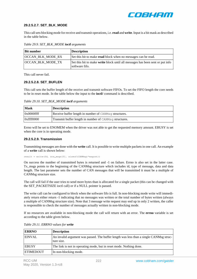
RCC-UMMay 2020, Version 1.3-rc8
222 www.cobham.com/gaisler
29.2.5.2.7. SET_BLK_MODE
This call sets blocking mode for receive and transmit operations, i.e. read and write. Input is a bit mask as describedin the table below.
Table 29.9. SET_BLK_MODE ioctl arguments
Bit number Description
OCCAN_BLK_MODE_RX Set this bit to make read block when no messages can be read.
OCCAN_BLK_MODE_TX Set this bit to make write block until all messages has been sent or put infosoftware fifo.
This call never fail.
29.2.5.2.8. SET_BUFLEN
This call sets the buffer length of the receive and transmit software FIFOs. To set the FIFO length the core needsto be in reset mode. In the table below the input to the ioctl/ command is described.
Table 29.10. SET_BLK_MODE ioctl arguments
Mask Description
0x0000ffff Receive buffer length in number of CANMsg structures.
0xffff0000 Transmit buffer length in number of CANMsg structures.
Errno will be set to ENOMEM when the driver was not able to get the requested memory amount. EBUSY is setwhen the core is in operating mode.
29.2.5.2.9. Transmission
Transmitting messages are done with the write call. It is possible to write multiple packets in one call. An exampleof a write call is shown below:
result = write(fd, &tx_msgs[0], sizeof(CANMsg)*msgcnt))
On success the number of transmitted bytes is returned and -1 on failure. Errno is also set in the latter case.Tx_msgs points to the beginning of the CANMsg structure which includes id, type of message, data and datalength. The last parameter sets the number of CAN messages that will be transmitted it must be a multiple ofCANMsg structure size.
The call will fail if the user tries to send more bytes than is allocated for a single packet (this can be changed withthe SET_PACKETSIZE ioctl call) or if a NULL pointer is passed.
The write call can be configured to block when the software fifo is full. In non-blocking mode write will immedi-ately return either return -1 indicating that no messages was written or the total number of bytes written (alwaysa multiple of CANMsg structure size). Note that 3 message write request may end up in only 2 written, the calleris responsible to check the number of messages actually written in non-blocking mode.
If no resources are available in non-blocking mode the call will return with an error. The errno variable is setaccording to the table given below.
Table 29.11. ERRNO values for write
ERRNO Description
EINVAL An invalid argument was passed. The buffer length was less than a single CANMsg struc-ture size.
EBUSY The link is not in operating mode, but in reset mode. Nothing done.
ETIMEDOUT In non-blocking mode.

RCC-UMMay 2020, Version 1.3-rc8
223 www.cobham.com/gaisler
ERRNO Description
EIO Calling task was woken up from blocking mode by a bus off error. The CAN core has en-tered reset mode. Further calls to read or write will fail until the ioctl command STARTis issued again.
Each Message has an individual set of options controlled in the CANMsg structure. See the data structure subsec-tion for structure member descriptions.
29.2.6. Reception
Reception is done using the read call. An example is shown below:
CANMsg rx_msgs[5];
len = read(fd, rx_msgs, sizeof(rx_msgs));
The requested number of bytes to be read is given in the third argument. The messages will be stored in rx_msgs.The actual number of received bytes (a multiple of sizeof(CANMsg)) is returned by the function on success and-1 on failure. In the latter case errno is also set.
The CANMsg data structure is described in the data structure subsection.
The call will fail if a null pointer is passed, invalid buffer length, the CAN core is in reset mode or due to a busoff error in blocking mode.
The blocking behaviour can be set using ioctl calls. In blocking mode the call will block until at least one packethas been received. In non-blocking mode, the call will return immediately and if no packet was available -1 isreturned and errno set appropriately. The table below shows the different errno values is returned.
Table 29.12. ERRNO values for readcalls.
ERRNO Description
EINVAL AA NULL pointer was passed as the data pointer or the length was illegal.
EBUSY CAN core is in reset mode. Swtich to operating mode by issuing a START ioctlcommand.

RCC-UMMay 2020, Version 1.3-rc8
224 www.cobham.com/gaisler
Chapter 30. SatCAN driver (SatCAN)
30.1. Introduction
This document is intended as an aid in getting started developing with the GRLIB wrapper for the SatCAN coreusing the driver described in this document. It briefly takes the reader through some of the most important steps inusing the driver such as setting up a connection, configuring the driver, reading and writing CAN messages. Thereader is assumed to be well acquainted with the operation of the SatCAN core and RTEMS.
30.1.1. SatCAN Hardware Wrapper
See the SatCAN wrapper manual.
30.1.2. Software Driver
The driver provides means for processes and threads to send and receive messages and provides callback functionsfor SatCAN wrapper interrupts.
All core registers can be accessed via Input/Output-control (ioctl) calls.
30.1.3. Examples
There is a simple example available, it illustrates how to set up a connection, reading and writing messages usingthe SATCAN driver. It is made up of two tasks communicating with each other where one task uses the OC_CANdriver and the other the SatCAN driver. To be able to run the example one must have the cores connected together.The current example is tailored for with a configuration matching GR712RC and also initializes the CAN_MUXRTEMS driver which is described in a separate document.
The example can be found under the samples directory and consists of the files samples/rtems-occan.c,occan_lib.c and occan_lib.h.
30.2. User interface
The RTEMS SATCAN driver supports the standard accesses to file descriptors such as read, write and ioctl.User applications should include the SATCAN driver's header file, satcan.h, which contains definitions of allnecessary data structures and defines used when accessing the driver. An example application using the driver isprovided in the samples directory.
30.2.1. Driver registration
The registration of the driver is crucial for threads and processes to be able to access the driver using standardmeans, such as open. The function satcan_register whose prototype is provided in satcan.h is used forregistering the driver. It returns 0 on success and 1 on failure. A typical register call from the LEON3 Init task:
if ( satcan_register(&satcan_conf) ) printf(“SatCAN register Failed\n”);
The second argument to the function is the SatCAN configuration structure. The contents of this structure isdescribed below:
typedef struct { int nodeno; int dps; void (*ahb_irq_callback)(void); void (*pps_irq_callback)(void); void (*m5_irq_callback)(void); void (*m4_irq_callback)(void); void (*m3_irq_callback)(void); void (*m2_irq_callback)(void); void (*m1_irq_callback)(void); void (*sync_irq_callback)(void); void (*can_irq_callback)(unsigned int fifo);} satcan_config;
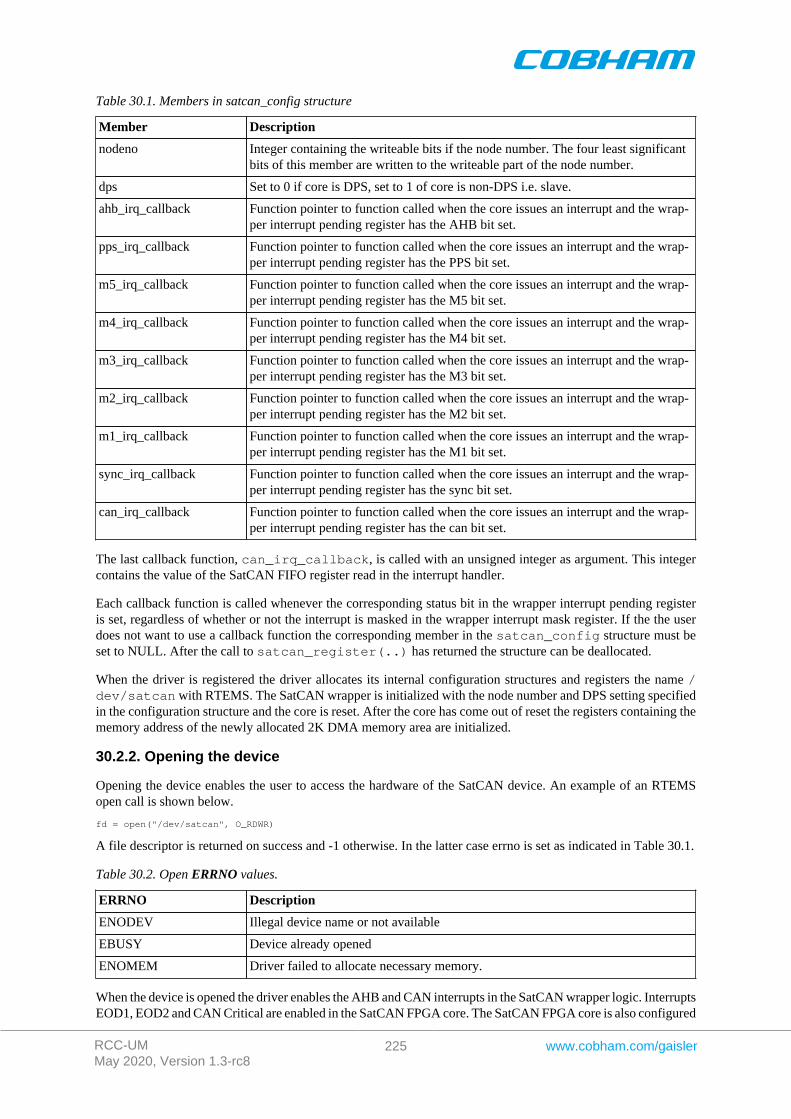
RCC-UMMay 2020, Version 1.3-rc8
225 www.cobham.com/gaisler
Table 30.1. Members in satcan_config structure
Member Description
nodeno Integer containing the writeable bits if the node number. The four least significantbits of this member are written to the writeable part of the node number.
dps Set to 0 if core is DPS, set to 1 of core is non-DPS i.e. slave.
ahb_irq_callback Function pointer to function called when the core issues an interrupt and the wrap-per interrupt pending register has the AHB bit set.
pps_irq_callback Function pointer to function called when the core issues an interrupt and the wrap-per interrupt pending register has the PPS bit set.
m5_irq_callback Function pointer to function called when the core issues an interrupt and the wrap-per interrupt pending register has the M5 bit set.
m4_irq_callback Function pointer to function called when the core issues an interrupt and the wrap-per interrupt pending register has the M4 bit set.
m3_irq_callback Function pointer to function called when the core issues an interrupt and the wrap-per interrupt pending register has the M3 bit set.
m2_irq_callback Function pointer to function called when the core issues an interrupt and the wrap-per interrupt pending register has the M2 bit set.
m1_irq_callback Function pointer to function called when the core issues an interrupt and the wrap-per interrupt pending register has the M1 bit set.
sync_irq_callback Function pointer to function called when the core issues an interrupt and the wrap-per interrupt pending register has the sync bit set.
can_irq_callback Function pointer to function called when the core issues an interrupt and the wrap-per interrupt pending register has the can bit set.
The last callback function, can_irq_callback, is called with an unsigned integer as argument. This integercontains the value of the SatCAN FIFO register read in the interrupt handler.
Each callback function is called whenever the corresponding status bit in the wrapper interrupt pending registeris set, regardless of whether or not the interrupt is masked in the wrapper interrupt mask register. If the the userdoes not want to use a callback function the corresponding member in the satcan_config structure must beset to NULL. After the call to satcan_register(..) has returned the structure can be deallocated.
When the driver is registered the driver allocates its internal configuration structures and registers the name /dev/satcan with RTEMS. The SatCAN wrapper is initialized with the node number and DPS setting specifiedin the configuration structure and the core is reset. After the core has come out of reset the registers containing thememory address of the newly allocated 2K DMA memory area are initialized.
30.2.2. Opening the device
Opening the device enables the user to access the hardware of the SatCAN device. An example of an RTEMSopen call is shown below.
fd = open("/dev/satcan", O_RDWR)
A file descriptor is returned on success and -1 otherwise. In the latter case errno is set as indicated in Table 30.1.
Table 30.2. Open ERRNO values.
ERRNO Description
ENODEV Illegal device name or not available
EBUSY Device already opened
ENOMEM Driver failed to allocate necessary memory.
When the device is opened the driver enables the AHB and CAN interrupts in the SatCAN wrapper logic. InterruptsEOD1, EOD2 and CAN Critical are enabled in the SatCAN FPGA core. The SatCAN FPGA core is also configured
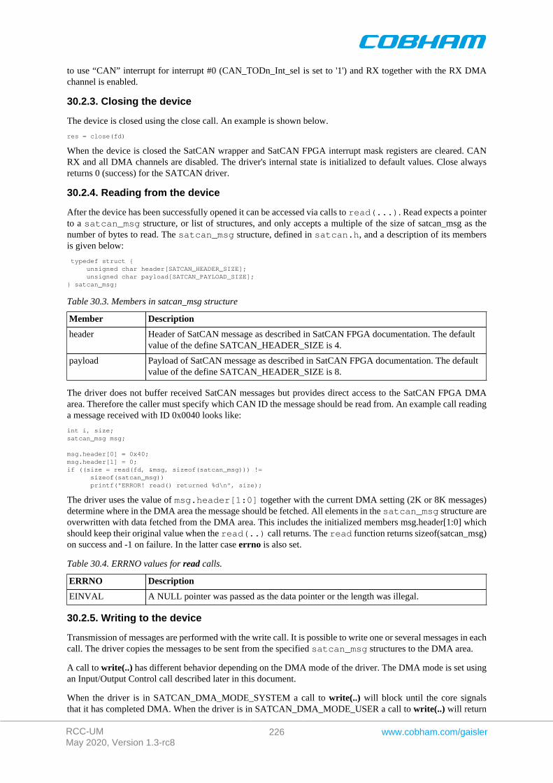
RCC-UMMay 2020, Version 1.3-rc8
226 www.cobham.com/gaisler
to use “CAN” interrupt for interrupt #0 (CAN_TODn_Int_sel is set to '1') and RX together with the RX DMAchannel is enabled.
30.2.3. Closing the device
The device is closed using the close call. An example is shown below.
res = close(fd)
When the device is closed the SatCAN wrapper and SatCAN FPGA interrupt mask registers are cleared. CANRX and all DMA channels are disabled. The driver's internal state is initialized to default values. Close alwaysreturns 0 (success) for the SATCAN driver.
30.2.4. Reading from the device
After the device has been successfully opened it can be accessed via calls to read(...). Read expects a pointerto a satcan_msg structure, or list of structures, and only accepts a multiple of the size of satcan_msg as thenumber of bytes to read. The satcan_msg structure, defined in satcan.h, and a description of its membersis given below:
typedef struct { unsigned char header[SATCAN_HEADER_SIZE]; unsigned char payload[SATCAN_PAYLOAD_SIZE];} satcan_msg;
Table 30.3. Members in satcan_msg structure
Member Description
header Header of SatCAN message as described in SatCAN FPGA documentation. The defaultvalue of the define SATCAN_HEADER_SIZE is 4.
payload Payload of SatCAN message as described in SatCAN FPGA documentation. The defaultvalue of the define SATCAN_HEADER_SIZE is 8.
The driver does not buffer received SatCAN messages but provides direct access to the SatCAN FPGA DMAarea. Therefore the caller must specify which CAN ID the message should be read from. An example call readinga message received with ID 0x0040 looks like:
int i, size;satcan_msg msg;
msg.header[0] = 0x40;msg.header[1] = 0;if ((size = read(fd, &msg, sizeof(satcan_msg))) != sizeof(satcan_msg)) printf("ERROR! read() returned %d\n", size);
The driver uses the value of msg.header[1:0] together with the current DMA setting (2K or 8K messages)determine where in the DMA area the message should be fetched. All elements in the satcan_msg structure areoverwritten with data fetched from the DMA area. This includes the initialized members msg.header[1:0] whichshould keep their original value when the read(..) call returns. The read function returns sizeof(satcan_msg)on success and -1 on failure. In the latter case errno is also set.
Table 30.4. ERRNO values for read calls.
ERRNO Description
EINVAL A NULL pointer was passed as the data pointer or the length was illegal.
30.2.5. Writing to the device
Transmission of messages are performed with the write call. It is possible to write one or several messages in eachcall. The driver copies the messages to be sent from the specified satcan_msg structures to the DMA area.
A call to write(..) has different behavior depending on the DMA mode of the driver. The DMA mode is set usingan Input/Output Control call described later in this document.
When the driver is in SATCAN_DMA_MODE_SYSTEM a call to write(..) will block until the core signalsthat it has completed DMA. When the driver is in SATCAN_DMA_MODE_USER a call to write(..) will return
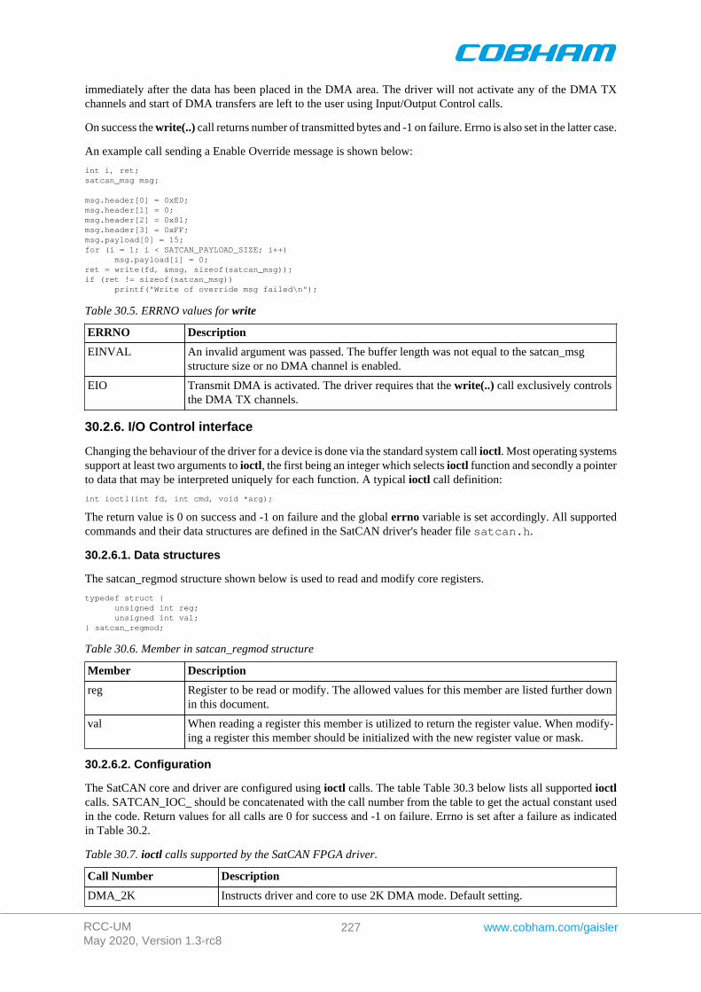
RCC-UMMay 2020, Version 1.3-rc8
227 www.cobham.com/gaisler
immediately after the data has been placed in the DMA area. The driver will not activate any of the DMA TXchannels and start of DMA transfers are left to the user using Input/Output Control calls.
On success the write(..) call returns number of transmitted bytes and -1 on failure. Errno is also set in the latter case.
An example call sending a Enable Override message is shown below:
int i, ret;satcan_msg msg;
msg.header[0] = 0xE0;msg.header[1] = 0;msg.header[2] = 0x81;msg.header[3] = 0xFF;msg.payload[0] = 15;for (i = 1; i < SATCAN_PAYLOAD_SIZE; i++) msg.payload[i] = 0;ret = write(fd, &msg, sizeof(satcan_msg));if (ret != sizeof(satcan_msg)) printf("Write of override msg failed\n");
Table 30.5. ERRNO values for write
ERRNO Description
EINVAL An invalid argument was passed. The buffer length was not equal to the satcan_msgstructure size or no DMA channel is enabled.
EIO Transmit DMA is activated. The driver requires that the write(..) call exclusively controlsthe DMA TX channels.
30.2.6. I/O Control interface
Changing the behaviour of the driver for a device is done via the standard system call ioctl. Most operating systemssupport at least two arguments to ioctl, the first being an integer which selects ioctl function and secondly a pointerto data that may be interpreted uniquely for each function. A typical ioctl call definition:
int ioctl(int fd, int cmd, void *arg);
The return value is 0 on success and -1 on failure and the global errno variable is set accordingly. All supportedcommands and their data structures are defined in the SatCAN driver's header file satcan.h.
30.2.6.1. Data structures
The satcan_regmod structure shown below is used to read and modify core registers.
typedef struct { unsigned int reg; unsigned int val;} satcan_regmod;
Table 30.6. Member in satcan_regmod structure
Member Description
reg Register to be read or modify. The allowed values for this member are listed further downin this document.
val When reading a register this member is utilized to return the register value. When modify-ing a register this member should be initialized with the new register value or mask.
30.2.6.2. Configuration
The SatCAN core and driver are configured using ioctl calls. The table Table 30.3 below lists all supported ioctlcalls. SATCAN_IOC_ should be concatenated with the call number from the table to get the actual constant usedin the code. Return values for all calls are 0 for success and -1 on failure. Errno is set after a failure as indicatedin Table 30.2.
Table 30.7. ioctl calls supported by the SatCAN FPGA driver.
Call Number Description
DMA_2K Instructs driver and core to use 2K DMA mode. Default setting.
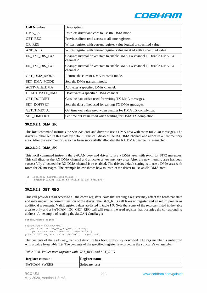
RCC-UMMay 2020, Version 1.3-rc8
228 www.cobham.com/gaisler
Call Number Description
DMA_8K Instructs driver and core to use 8K DMA mode.
GET_REG Provides direct read access to all core registers.
OR_REG Writes register with current register value logical or specified value.
AND_REG Writes register with current register value masked with a specified value.
EN_TX1_DIS_TX2 Changes internal driver state to enable DMA TX channel 1, Disable DMA TXchannel 2.
EN_TX1_DIS_TX1 Changes internal driver state to enable DMA TX channel 1, Disable DMA TXchannel 2.
GET_DMA_MODE Returns the current DMA transmit mode.
SET_DMA_MODE Sets the DMA transmit mode.
ACTIVATE_DMA Activates a specified DMA channel.
DEACTIVATE_DMA Deactivates a specified DMA channel.
GET_DOFFSET Gets the data offset used for writing TX DMA messages.
SET_DOFFSET Sets the data offset used for writing TX DMA messages.
GET_TIMEOUT Get time out value used when waiting for DMA TX completion.
SET_TIMEOUT Set time out value used when waiting for DMA TX completion.
30.2.6.2.1. DMA_2K
This ioctl command instructs the SatCAN core and driver to use a DMA area with room for 2048 messages. Thedriver is initialized in this state by default. This call disables the RX DMA channel and allocates a new memoryarea. After the new memory area has been successfully allocated the RX DMA channel is re-enabled.
30.2.6.2.2. DMA_8K
This ioctl command instructs the SatCAN core and driver to use a DMA area with room for 8192 messages.This call disables the RX DMA channel and allocates a new memory area. After the new memory area has beensuccessfully allocated the RX DMA channel is re-enabled. The drivers default setting is to use a DMA area withroom for 2K messages. The example below shows how to instruct the driver to use an 8K DMA area:
if (ioctl(fd, SATCAN_IOC_DMA_8K)) { printf("ERROR: Failed to enable 8K DMA area\n");}
30.2.6.2.3. GET_REG
This call provides read access to all the core's registers. Note that reading a register may affect the hardware stateand may impact the correct function of the driver. The GET_REG call takes an register and an return pointer asadditional arguments. Valid register values are listed in table 1.9. Note that some of the registers listed in the tablea write only and a SATCAN_IOC_GET_REG call will return the read register that occupies the correspondingaddress. An example of reading the SatCAN CmdReg1:
satcan_regmod regmod;
regmod.reg = SATCAN_CMD1;if (ioctl(fd, SATCAN_IOC_GET_REG, ®mod)) printf("Failed to read CMD1 register\n");printf("CMD1 register value: 0x%08x\n", regmod.val);
The contents of the satcan_regmod structure has been previously described. The reg member is initializedwith a value from table 1.9. The contents of the specified register is returned in the structure's val member.
Table 30.8. Values used together with GET_REG and SET_REG
Register constant Register name
SATCAN_SWRES Software reset
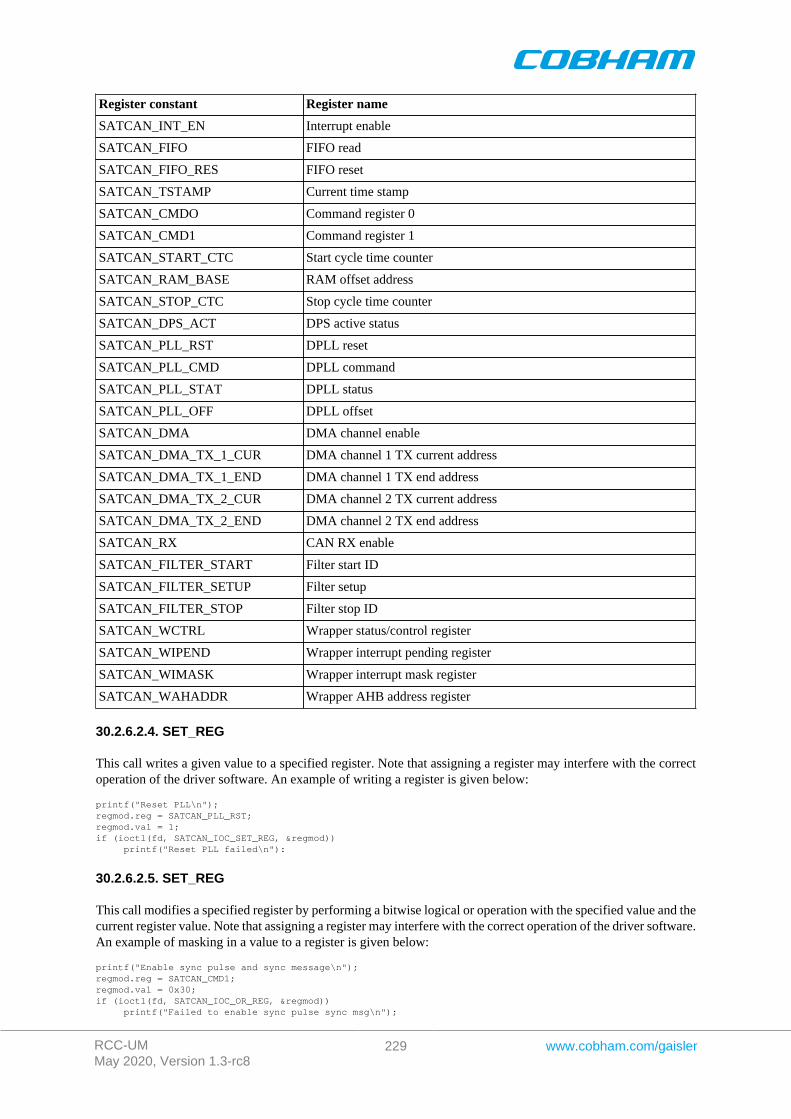
RCC-UMMay 2020, Version 1.3-rc8
229 www.cobham.com/gaisler
Register constant Register name
SATCAN_INT_EN Interrupt enable
SATCAN_FIFO FIFO read
SATCAN_FIFO_RES FIFO reset
SATCAN_TSTAMP Current time stamp
SATCAN_CMDO Command register 0
SATCAN_CMD1 Command register 1
SATCAN_START_CTC Start cycle time counter
SATCAN_RAM_BASE RAM offset address
SATCAN_STOP_CTC Stop cycle time counter
SATCAN_DPS_ACT DPS active status
SATCAN_PLL_RST DPLL reset
SATCAN_PLL_CMD DPLL command
SATCAN_PLL_STAT DPLL status
SATCAN_PLL_OFF DPLL offset
SATCAN_DMA DMA channel enable
SATCAN_DMA_TX_1_CUR DMA channel 1 TX current address
SATCAN_DMA_TX_1_END DMA channel 1 TX end address
SATCAN_DMA_TX_2_CUR DMA channel 2 TX current address
SATCAN_DMA_TX_2_END DMA channel 2 TX end address
SATCAN_RX CAN RX enable
SATCAN_FILTER_START Filter start ID
SATCAN_FILTER_SETUP Filter setup
SATCAN_FILTER_STOP Filter stop ID
SATCAN_WCTRL Wrapper status/control register
SATCAN_WIPEND Wrapper interrupt pending register
SATCAN_WIMASK Wrapper interrupt mask register
SATCAN_WAHADDR Wrapper AHB address register
30.2.6.2.4. SET_REG
This call writes a given value to a specified register. Note that assigning a register may interfere with the correctoperation of the driver software. An example of writing a register is given below:
printf("Reset PLL\n");regmod.reg = SATCAN_PLL_RST;regmod.val = 1;if (ioctl(fd, SATCAN_IOC_SET_REG, ®mod)) printf("Reset PLL failed\n"):
30.2.6.2.5. SET_REG
This call modifies a specified register by performing a bitwise logical or operation with the specified value and thecurrent register value. Note that assigning a register may interfere with the correct operation of the driver software.An example of masking in a value to a register is given below:
printf("Enable sync pulse and sync message\n");regmod.reg = SATCAN_CMD1;regmod.val = 0x30;if (ioctl(fd, SATCAN_IOC_OR_REG, ®mod)) printf("Failed to enable sync pulse sync msg\n");
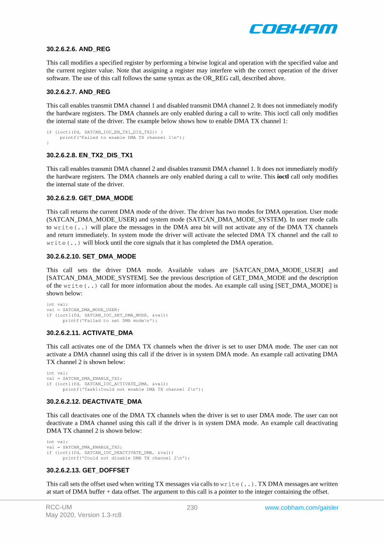
RCC-UMMay 2020, Version 1.3-rc8
230 www.cobham.com/gaisler
30.2.6.2.6. AND_REG
This call modifies a specified register by performing a bitwise logical and operation with the specified value andthe current register value. Note that assigning a register may interfere with the correct operation of the driversoftware. The use of this call follows the same syntax as the OR_REG call, described above.
30.2.6.2.7. AND_REG
This call enables transmit DMA channel 1 and disabled transmit DMA channel 2. It does not immediately modifythe hardware registers. The DMA channels are only enabled during a call to write. This ioctl call only modifiesthe internal state of the driver. The example below shows how to enable DMA TX channel 1:
if (ioctl(fd, SATCAN_IOC_EN_TX1_DIS_TX2)) { printf("Failed to enable DMA TX channel 1\n");}
30.2.6.2.8. EN_TX2_DIS_TX1
This call enables transmit DMA channel 2 and disables transmit DMA channel 1. It does not immediately modifythe hardware registers. The DMA channels are only enabled during a call to write. This ioctl call only modifiesthe internal state of the driver.
30.2.6.2.9. GET_DMA_MODE
This call returns the current DMA mode of the driver. The driver has two modes for DMA operation. User mode(SATCAN_DMA_MODE_USER) and system mode (SATCAN_DMA_MODE_SYSTEM). In user mode callsto write(..) will place the messages in the DMA area bit will not activate any of the DMA TX channelsand return immediately. In system mode the driver will activate the selected DMA TX channel and the call towrite(..) will block until the core signals that it has completed the DMA operation.
30.2.6.2.10. SET_DMA_MODE
This call sets the driver DMA mode. Available values are [SATCAN_DMA_MODE_USER] and[SATCAN_DMA_MODE_SYSTEM]. See the previous description of GET_DMA_MODE and the descriptionof the write(..) call for more information about the modes. An example call using [SET_DMA_MODE] isshown below:
int val;val = SATCAN_DMA_MODE_USER;if (ioctl(fd, SATCAN_IOC_SET_DMA_MODE, &val)) printf("Failed to set DMA mode\n");
30.2.6.2.11. ACTIVATE_DMA
This call activates one of the DMA TX channels when the driver is set to user DMA mode. The user can notactivate a DMA channel using this call if the driver is in system DMA mode. An example call activating DMATX channel 2 is shown below:
int val;val = SATCAN_DMA_ENABLE_TX2;if (ioctl(fd, SATCAN_IOC_ACTIVATE_DMA, &val)) printf("Task1:Could not enable DMA TX channel 2\n");
30.2.6.2.12. DEACTIVATE_DMA
This call deactivates one of the DMA TX channels when the driver is set to user DMA mode. The user can notdeactivate a DMA channel using this call if the driver is in system DMA mode. An example call deactivatingDMA TX channel 2 is shown below:
int val;val = SATCAN_DMA_ENABLE_TX2;if (ioctl(fd, SATCAN_IOC_DEACTIVATE_DMA, &val)) printf("Could not disable DMA TX channel 2\n");
30.2.6.2.13. GET_DOFFSET
This call sets the offset used when writing TX messages via calls to write(..). TX DMA messages are writtenat start of DMA buffer + data offset. The argument to this call is a pointer to the integer containing the offset.

RCC-UMMay 2020, Version 1.3-rc8
231 www.cobham.com/gaisler
30.2.6.2.14. SET_DOFFSET
This call returns the offset used when writing TX messages via calls to write(..). TX DMA messages arewritten at start of DMA buffer + data offset. The argument to this call is a pointer to an integer. The integer isassigned the current offset.
30.2.6.2.15. GET_TIMEOUT
This call returns the time out value that the write(..) call uses when waiting for TX DMA completion. Theargument is a pointer to an [rtems_interval] type.
30.2.6.2.16. SET_TIMEOUT
This call sets the time out value that the write(..) call uses when waiting for TX DMA completion. Theargument is a pointer to an [rtems_interval] type.
RCC-UMMay 2020, Version 1.3-rc8
232 www.cobham.com/gaisler
Chapter 31. CAN_MUX driver (CAN_MUX)
31.1. Introduction
This document is intended as an aid in getting started developing with GRLIB CAN_MUX core using the driverdescribed in this document. It briefly takes the reader through some of the most important steps in using the driversuch as configuring the driver and using Input/Output-control calls to modify the hardware state. The reader isassumed to be well acquainted with the operation of the CAN_MUX core and RTEMS.
31.1.1. CAN_MUX Hardware
See the GR712RC or CAN_MUX core documentation.
31.1.2. Software Driver
The driver provides means for setting the CAN_MUX MUX control register.
31.1.3. Examples
The rtems-satcan example uses the CAN_MUX driver.
31.2. User interface
The RTEMS CAN_MUX driver supports the standard accesses to file descriptors such as read, write and ioctl.The implementation of read and write calls are dummy functions. The driver is controlled exclusively via ioctl.User applications should include the CAN_MUX driver's header file, canmux.h, which contains definitions ofall necessary values and functions used when accessing the driver.
31.2.1. Driver registration
The registration of the driver is crucial for threads and processes to be able to access the driver using standardmeans, such as open. The function canmux_register whose prototype is provided in canmux.h is used forregistering the driver. The function returns 0 on success. A typical register call from the LEON3 Init task:
if ( canmux_register(&amba_conf) ) printf(“CAN_MUX register failed\n”);
31.2.2. Opening the device
Opening the device enables the user to access the hardware of the CAN_MUX core. An example of an RTEMSopen call is shown below.
fd = open("/dev/canmux", O_RDWR)
A file descriptor is returned on success and -1 otherwise. In the latter case errno is set as indicated in Table 31.1.
Table 31.1. Open errno values.
ERRNO Description
ENODEV Illegal device name or not available
EBUSY Device already opened
31.2.3. Closing the device
The device is closed using the close call. An example is shown below.
res = close(fd)
Close always returns 0 (success) for the CAN_MUX driver.
31.2.4. I/O Control interface
The driver and hardware is controlled via the standard system call ioctl. Most operating systems support at leasttwo arguments to ioctl, the first being an integer which selects ioctl function and secondly a pointer to data thatmay be interpreted uniquely for each function. A typical ioctl call definition:
RCC-UMMay 2020, Version 1.3-rc8
233 www.cobham.com/gaisler
int ioctl(int fd, int cmd, void *arg);
The return value is 0 on success and -1 on failure and the global errno variable is set accordingly. The CAN_MUXdriver does not use any additonal data except for the integer that selects the ioctl function. All supported commandsare defined in the CAN_MUX driver's header file canmux.h and are described further down in this document.
31.2.4.1. Configuration
The CAN_MUX core and driver is controlled using ioctl calls. The Table 31.3 below lists all supported ioctl calls.OCCAN_IOC_ should be concatenated with the call name from the table to get the actual constant used in the code.Return values for all calls are 0 for success and -1 on failure. Errno is set after a failure as indicated in Table 31.2.
Table 31.2. ERRNO values for ioctl calls.
ERRNO Description
EINVAL Null pointer or an out of range value was given as the argument.
Table 31.3. ioctl calls supported by the CAN_MUX driver.
Call Number Description
BUSA_SATCAN Routes bus A to SatCAN core
BUSA_OCCAN1 Routes bus A to OC-CAN 1 core
BUSB_SATCAN Routes bus B to SatCAN core
BUSB_OCCAN2 Routes bus B to OC-CAN 2 core
RCC-UMMay 2020, Version 1.3-rc8
234 www.cobham.com/gaisler
Chapter 32. GRASCS driver
32.1. Introduction
This document is intended as an introduction to the RTEMS driver for the Gaisler ASCS core. It is recommendedthat the reader also has access to the GRASCS IP core documentation when reading this document.
32.1.1. Software driver
The driver allows the developer of application software to communicate with the GRASCS core. It supplies thefunctions to initialize the core, send and receive data, start and stop synchronization etc. The complete user inter-face is described in more detail in Section 32.2 below. The driver is thread safe with the following two exceptions:ASCS_etr_select, ASCS_TC_sync_start, and ASCS_TC_sync_stop can not be called from different threads, andASCS_start and ASCS_stop can not be called from different threads. The driver supports all the different config-urations of the GRASCS core that is mentioned in the GRASCS IP core documentation.
32.1.2. Examples
A demonstration software which shows how to use the driver interface is distributed together with the driver. Thesoftware initialize the core, start the serial and synchronization interfaces, perform data writes and data reads andthen stops the interfaces again. The software has been developed for pure demonstration purposes and the effectsof the transactions performed on a real ASCS slave are unknown.
32.2. User interface
In Table 32.1 all the functions of the GRASCS driver interface are listed. To gain access to the functions a userapplication should include the GRASCS driver's header file.
Table 32.1. GRASCS driver interface
Function name Described in Short description
ASCS_init Section 32.2.1 Initializes driver and GRASCS core
ASCS_input_select Section 32.2.2 Selects slave
ASCS_etr_select Section 32.2.3 Select source for synchronization pulse
ASCS_start Section 32.2.4 Starts serial interface
ASCS_stop Section 32.2.5 Stops serial interface
ASCS_iface_status Section 32.2.6 Report status of serial and synchronization interfaces
ASCS_TC_send Section 32.2.7 Performs a data write (TC)
ASCS_TC_send_block Section 32.2.8 Performs a number of TCs
ASCS_TC_sync_start Section 32.2.9 Starts synchronization interface
ASCS_TC_sync_stop Section 32.2.10 Stops synchronization interface
ASCS_TM_recv Section 32.2.11 Performs a data read (TM)
ASCS_TM_recv_block Section 32.2.12 Performs a number of TMs
32.2.1. ASCS_init
Prototype int ASCS_init()
Argument This function does not take any arguments
Return value: 0 on success, -1 on failure
Description: This function must be called before any other functions in the ASCS driver are called.ASCS_init initializes the driver and resets the core. When the function returns all of thecores registers will have their default values, which means that both the serial interfaceand synchronization interface are stopped.

RCC-UMMay 2020, Version 1.3-rc8
235 www.cobham.com/gaisler
32.2.2. ASCS_input_select
Prototype int ASCS_input_select(int slave)
Argument slave
Description The number of the slave the core should listen to during a TM
Return value: 0 on success, -GRASCS_ERROR_CAPFAULT if slave value is invalid, -GRASCS_ERROR_TRANSACTIVE if a TM is in progress
Description: This function sets the bits in the core's command register that control which slave data in-put is valid during a TM. Valid range of the input 0 – (nslaves-1), where nslaves is thenumber of slaves the core has been configured to communicate with (nslaves generic).
32.2.3. ASCS_etr_select
Prototype int ASCS_etr_select(int etr, int freq)
Argument
etr
freq
Description
The source for the etr signal, valid range 0 - 6
The ETR frequency in Hz
Return value: 0 on success, -GRASCS_ERROR_CAPFAULT if arguments have invalid values, -GRASCS_ERROR_STARTSTOP if synchronization interface is running
Description: This function need to be called if the source of the ETR synchronization pulse shouldbe changed. The etr input specifies which source to use, where 0 means internal counterand 1 – 6 means external time marker 1 - 6. The freq input specifies the frequency ofthe etr signal. If etr is not 0 then the freq argument need to be the same as the frequen-cy of the external time marker that is used. The core can not generate an ETR pulse ofone frequency from an external time marker of a different frequency. This function,ASCS_TC_sync_start and ASCS_TC_sync_stop can not be called from different threads.
32.2.4. ASCS_start
Prototype int ASCS_start()
Argument This function does not take any arguments
Return value: None
Description: A call to this function starts the core's serial interface and the core is then ready to per-form transactions. This function and ASCS_stop can not be called from different threads.
32.2.5. ASCS_stop
Prototype int ASCS_stop()
Argument This function does not take any arguments
Return value: None
Description: A call to this function stops the core's serial interface. This function will block un-til any possible call to ASCS_TC_send, ASCS_TC_send_block, ASCS_TM_recv orASCS_TM_recv_block has returned. This function and ASCS_start can not be calledfrom different threads.
32.2.6. ASCS_iface_status
Prototype int ASCS_iface_status()
Argument This function does not take any arguments
Return value: 0 if both serial interface and synchronization interface are stopped, 1 if serial interface isrunning and synchronization interface is stopped, 2 if serial interface is stopped and syn-chronization interface is running, 3 if both interfaces are running.

RCC-UMMay 2020, Version 1.3-rc8
236 www.cobham.com/gaisler
Description: Uses the internal driver status and the value of the core's status register to report if serialand synchronization interfaces are running or stopped.
32.2.7. ASCS_TC_send
Prototype int ASCS_TC_send(int *word)
Argument
word
ntrans
Description
Pointer to data that should be sent as a telecommands. The argument is handled as apoint erto a short int if the core is configured to send 16-bit words, or a char pointer for8-bit words.
The number of telecommands that should be sent
Return value: 0 on success, -GRASCS_ERROR_TRANSACTIVE if TC could not be started becausesome other transaction is in progress, - GRASCS_ERROR_STARTSTOP if TC could notbe started because serial interface is stopped.
Description: Sends a telecommand with the data pointed to by the word argument. If the TC is startedthe function blocks until the transaction is complete. If the TC can not be started the func-tion returns with an error code. This function is thread safe.
32.2.8. ASCS_TC_send_block
Prototype int ASCS_TC_send_block(int *block,int ntrans)
Argument
blcok
ntrans
Description
Pointer to the start a block of data that should be sent as a number of telecommands. Theblock argument is handled as a point erto a block of short int if the core is configured tosend 16-bit words, or a char pointer for 8-bit words.
The number of telecommands that should be sent
Return value: 0 on success, -GRASCS_ERROR_TRANSACTIVE if TC could not be started becausesome other transaction is in progress, - GRASCS_ERROR_STARTSTOP if TC could notbe started because serial interface is stopped.
Description: Sends a number of telecommands with the data pointed to be the block argument. If thefirst TC is started the function blocks until all the transaction are complete. If the first TCcan not be started the function returns with an error code. This function is thread safe.
32.2.9. ASCS_TC_sync_start
Prototype int ASCS_TC_sync_start(void)
Argument This function does not take any arguments
Return value: None
Description: Starts the synchronization interface. There might be a delay between the time this func-tion is called and the time the interface is actually started, depending on whether a TM isactive or not. Software can poll ASCS_iface_status to find out when interface is running.The first pulse on the synchronization interface might be delay with up to one period de-pending on the source used for the ETR signal. This function, ASCS_TC_sync_stop andASCS_etr_select can not be called from different threads.
32.2.10. ASCS_TC_sync_stop
Prototype int ASCS_TC_sync_stop(void)
Argument this function does not take any arguments
Return value: None
RCC-UMMay 2020, Version 1.3-rc8
237 www.cobham.com/gaisler
Description: Stops the synchronization interface. In order not to prematurely abort a ETR pulse theremight be a delay between the time this function is called and the time the interface is ac-tually stopped. Software can poll ASCS_iface_status to find out when the interface isstopped. This function, ASCS_TC_sync_start and ASCS_etr_select can not be calledfrom different threads.
32.2.11. ASCS_TM_recv
Prototype int ASCS_TM_recv(int *word)
Argument
word
Description
Pointer to where data received in a TM should be stored. The argument is handled as ashort int pointer if the core is configured to send 16-bit words, or a char pointer for 8-bitwords.
Return value: 0 on success, -GRASCS_ERROR_TRANSACTIVE if TM could not be started becausesome other transaction is in progress, -GRASCS_ERROR_STARTSTOP if TM could notbe started because serial interface is stopped.
Description: Starts a TM and stores the incoming data at the address word points to. If the TM can notbe started the function returns with an error code otherwise it blocks until the transactionis complete. This function is thread safe.
32.2.12. ASCS_TM_recv_block
Prototype int ASCS_TM_recv_block(int *block, int ntrans)
Argument
block
ntrans
Description
Pointer to the start of a block where data received in a number of TMs should be stored.The block argument is handled as a point erto a block of short int if the core is config-ured to send 16- bit words, or a char pointer for 8-bit words.
The number of TMs that should be sent
Return value: 0 on success, -GRASCS_ERROR_TRANSACTIVE if TM could not be started becausesome other transaction is in progress, -GRASCS_ERROR_STARTSTOP if TM could notbe started because serial interface is stopped.
Description: Starts a number of TMs and stores the incoming data with the beginning of the addressthat block points to. If the first TM can not be started the function returns with an errorcode otherwise it blocks until all the transactions are complete. This function is threadsafe.
32.3. Examples code
To use the GRASCS driver its header file should be included:
#include <grascs.h>
The driver must first be initialized, and the return value must be checked to see that the initialization went well:
status = ASCS_init();
if(status < 0) {
printf("ERROR: Failed to initialize ASCS driver\n");
exit(0);
}
printf("Successfully intialized ASCS driver\n");
When the ASCS_init function has been called the application can start calling the other functions as well. Belowis an example of how to call ASCS_TC_send_block and send ten TCs.

RCC-UMMay 2020, Version 1.3-rc8
238 www.cobham.com/gaisler
retval = ASCS_TC_send_block((int*)block,10);
if(retval < 0) {
if(retval == -GRASCS_ERROR_STARTSTOP)
printf("ERROR: Failed to start TC because serial interface neverstarted\n");
else if(retval == -GRASCS_ERROR_TRANSACTIVE)
printf("ERROR: Failed to start TC because a transaction is inprogress\n");
}

RCC-UMMay 2020, Version 1.3-rc8
239 www.cobham.com/gaisler
Chapter 33. APBUART console driver
33.1. Introduction
The RTEMS Driver Manager APBUART console driver is implemented using the RTEMS POSIX Termios sup-port. POSIX Termios is defined by IEEE Std 1003.1-2008 (POSIX.1-2008) which provides an oper-ating system independent interface to terminal devices. The RTEMS kernel provides the Termios specific parts ofthe interface, while the APBUART console driver implements the low-level hardware access.
Even though the APBUART driver is referred to as a console driver, and the Termios interface is a general terminalinterface, the driver can also be used as a general purpose UART driver.
33.1.1. Functioning mode
A device attached to the APBUART console driver can operate in one of three different functioning modes.
• Polled Mode (default)• Interrupt Driven Mode• Task Driven Mode
Polled mode is used by default and will leave calling tasks in a poll loop to wait for the requested operation tocomplete. Interrupt driven mode uses the APBUART interrupt and FIFO functionality to prevent blocking thetask using the driver. In task driven mode, the RTEMS Termios layer creates daemon tasks which are activatedon APBUART interrupt and carries out the processing in task context.
The functioning mode is set at compile time using driver manager resources and can not be changed afterwards.For more information on the operating modes, see the document RTEMS BSP and Device Driver DevelopmentGuide. Note that Task Driven Mode is not supported in SMP environments.
33.1.2. Hardware support
APBUART devices are available in different hardware configurations with different capabilities. This driver usesthe following capababilities, if their presence is detected by the driver.
• RX/TX interrupt (depending on functioning mode as described below)• RX/TX FIFO• Delayed RX interrupt
33.2. User interface
The driver supports the standard accesses to file descriptors such as read(), write() and to Termios con-trol functions such as tcgetattr(), tcsetattr() and cfsetispeed(). User applications include theTermios header file <termios.h> which provides prototypes and definitions of all necessary data structuresand bit masks used when accessing a Termios file.
User operations specific to the APBUART driver are documented here, while common Termios operations aredocumented in IEEE Std 1003.1-2008 (POSIX.1-2008).
The APBUART console driver require the RTEMS Driver Manager.
33.2.1. Driver registration
The registration of the driver is crucial for threads and processes to be able to access the driver using standardmeans, such as open. The RTEMS I/O driver registration is performed automatically by the driver when UARThardware is found for the first time. The driver is called from the driver manager to handle detected UART hard-ware. In order for the driver manager to unite the UART driver with the UART hardware one must register thedriver to the driver manager. This process is described in the driver manager chapter.
33.2.2. Driver resource configuration
The driver can be configured at compile tile using driver resources as described in the driver manager chapter.Below is a description of configurable driver parameters. The driver parameters are unique per APBUART device.The parameters are all optional, the parameters only overrides the default values.
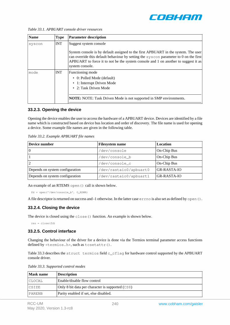
RCC-UMMay 2020, Version 1.3-rc8
240 www.cobham.com/gaisler
Table 33.1. APBUART console driver resources
Name Type Parameter description
syscon INT Suggest system console
System console is by default assigned to the first APBUART in the system. The usercan override this default behaviour by setting the syscon parameter to 0 on the firstAPBUART to force it to not be the system console and 1 on another to suggest it assystem console.
mode INT Functioning mode
• 0: Polled Mode (default)• 1: Interrupt Driven Mode• 2: Task Driven Mode
NOTE: NOTE: Task Driven Mode is not supported in SMP environments.
33.2.3. Opening the device
Opening the device enables the user to access the hardware of a APBUART device. Devices are identified by a filename which is constructed based on device bus location and order of discovery. The file name is used for openinga device. Some example file names are given in the following table.
Table 33.2. Example APBUART file names
Device number Filesystem name Location
0 /dev/console On-Chip Bus
1 /dev/console_b On-Chip Bus
2 /dev/console_c On-Chip Bus
Depends on system configuration /dev/rastaio0/apbuart0 GR-RASTA-IO
Depends on system configuration /dev/rastaio0/apbuart1 GR-RASTA-IO
An example of an RTEMS open() call is shown below.
fd = open("/dev/console_b", O_RDWR)
A file descriptor is returned on success and -1 otherwise. In the latter case errno is also set as defined by open().
33.2.4. Closing the device
The device is closed using the close() function. An example is shown below.
res = close(fd)
33.2.5. Control interface
Changing the behaviour of the driver for a device is done via the Termios terminal parameter access functionsdefined by <termios.h>, such as tcsetattr().
Table 33.3 describes the struct termios field c_cflag for hardware control supported by the APBUARTconsole driver.
Table 33.3. Supported control modes
Mask name Description
CLOCAL Enable/disable flow control
CSIZE Only 8 bit data per character is supported (CS8)
PARENB Parity enabled if set, else disabled.
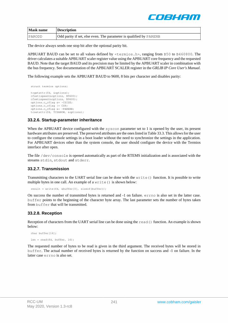
RCC-UMMay 2020, Version 1.3-rc8
241 www.cobham.com/gaisler
Mask name Description
PARODD Odd parity if set, else even. The parameter is qualified by PARENB
The device always sends one stop bit after the optional parity bit.
APBUART BAUD can be set to all values defined by <termios.h>, ranging from B50 to B460800. Thedriver calculates a suitable APBUART scaler register value using the APBUART core frequency and the requestedBAUD. Note that the target BAUD and its precision may be limited by the APBUART scaler in combination withthe bus frequency. See documentation of the APBUART SCALER register in the GRLIB IP Core User's Manual.
The following example sets the APBUART BAUD to 9600, 8 bits per character and disables parity:
struct termios options;
tcgetattr(fd, &options); cfsetispeed(&options, B9600); cfsetospeed(&options, B9600); options.c_cflag &= ~CSIZE; options.c_cflag |= CS8; options.c_cflag &= ~PARENB; tcsetattr(fd, TCSANOW, &options);
33.2.6. Startup-parameter inheritance
When the APBUART device configured with the syscon parameter set to 1 is opened by the user, its presenthardware attributes are preserved. The preserved attributes are the ones listed in Table 33.3. This allows for the userto configure the console settings in a boot loader without the need to synchronize the settings in the application.For APBUART devices other than the system console, the user should configure the device with the Termiosinterface after open.
The file /dev/console is opened automatically as part of the RTEMS initialization and is associated with thestreams stdin, stdout and stderr.
33.2.7. Transmission
Transmitting characters to the UART serial line can be done with the write() function. It is possible to writemultiple bytes in one call. An example of a write() is shown below:
result = write(fd, &buffer[0], sizeof(buffer));
On success the number of transmitted bytes is returned and -1 on failure. errno is also set in the latter case.buffer points to the beginning of the character byte array. The last parameter sets the number of bytes takenfrom buffer that will be transmitted.
33.2.8. Reception
Reception of characters from the UART serial line can be done using the read() function. An example is shownbelow:
char buffer[16];
len = read(fd, buffer, 16);
The requested number of bytes to be read is given in the third argument. The received bytes will be stored inbuffer. The actual number of received bytes is returned by the function on success and -1 on failure. In thelatter case errno is also set.
RCC-UMMay 2020, Version 1.3-rc8
242 www.cobham.com/gaisler
Chapter 34. SPICTRL GRLIB SPI master driver
34.1. Introduction
This section describes the SPICTRL Master driver available for RTEMS. The SPICTRL driver provides the nec-essary functions needed by the RTEMS I2C Library. The RTEMS I2C Library is used for both I2C and SPI. TheRTEMS I2C Library is not documented here.
The SPICTRL driver require the RTEMS Driver Manager.
34.1.1. SPI Hardware
The SPICTRL core is documented in the GR-IP core's manual. The driver supports multiple SPI cores.
34.1.2. Examples
There are two examples available, one that read and write data to a standard SPI FLASH and one that access aSD Card FAT file system. The SPI driver initialize the I2C Library when a SPI core is found and the applicationinitialize the higher level drivers.
The examples are part of the Gaisler RTEMS distribution, it can be found under /opt/rtems-5/src/sam-ples/rtems-spi.c and rtems-spi-sdcard.c.
34.2. User interface
The RTEMS SPICTRL SPI driver supports the RTEMS I2C Library operations and the simultaneous read/writeoperation available using the ioctl interface. The driver is united with SPICTRL cores by the driver manageras SPICTRL cores are found. During driver initialization the SPI driver initializes the RTEMS I2C Library andregisters the driver. The driver is registered with the name /dev/spi1, /dev/spi2 and so on.
An example application using the driver is provided in the samples directory distributed with the toolchain.
34.2.1. Driver registration
The registration of the driver is needed in order for the RTEMS I2C Library to know about the SPI hardwaredriver. The RTEMS I2C driver registration is performed automatically by the driver when SPICTRL hardwareis found for the first time. The driver is called from the driver manager to handle detected SPICTRL hardware.In order for the driver manager to unite the SPICTRL driver with the SPICTRL hardware one must register thedriver to the driver manager. This process is described in the driver manager chapter.
34.2.2. Accessing the SPI bus
The SPI bus can be accessed direct in RAW mode or by using a so called high level driver. The high level driversmust be connected with the SPICTRL driver by using the rtems_libi2c_register_drv function. The SD Cardhigher level driver does this automatically where as the memory driver needs the user to do this before initializingthe memory driver. The location of the higher level drivers and the RTEMS I2C Library is indicated in Table 34.1.All paths are given relative the RTEMS kernel source root.
Table 34.1. SPI source location
Source description Location
I2C Library cpukit/libi2c
High level drivers c/src/libchip/i2c
SPICTRL driver c/src/lib/libbsp/sparc/shared/spi
When accessing the driver in RAW mode a device node must be created manually in the file system by callingrtems_filesystem_make_dev_t and mknod with the correct major and minor number identifying theSPICTRL driver. The major number must be the same as the RTEMS I2C Library I/O driver major number,
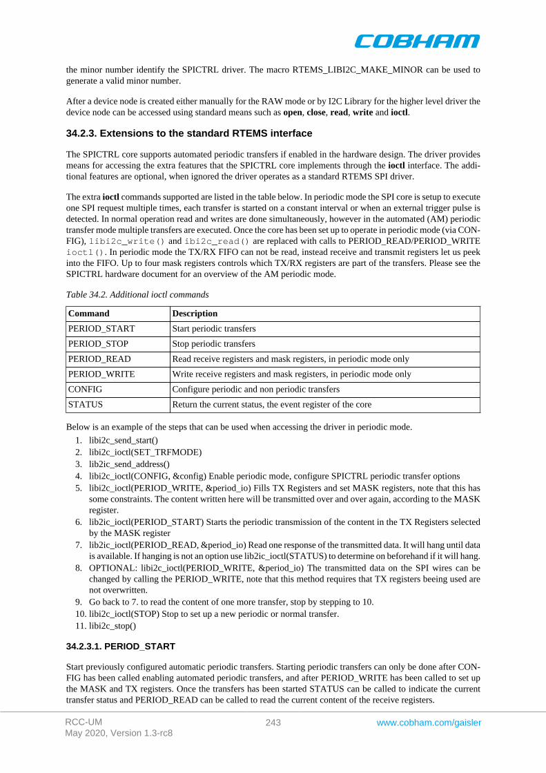
RCC-UMMay 2020, Version 1.3-rc8
243 www.cobham.com/gaisler
the minor number identify the SPICTRL driver. The macro RTEMS_LIBI2C_MAKE_MINOR can be used togenerate a valid minor number.
After a device node is created either manually for the RAW mode or by I2C Library for the higher level driver thedevice node can be accessed using standard means such as open, close, read, write and ioctl.
34.2.3. Extensions to the standard RTEMS interface
The SPICTRL core supports automated periodic transfers if enabled in the hardware design. The driver providesmeans for accessing the extra features that the SPICTRL core implements through the ioctl interface. The addi-tional features are optional, when ignored the driver operates as a standard RTEMS SPI driver.
The extra ioctl commands supported are listed in the table below. In periodic mode the SPI core is setup to executeone SPI request multiple times, each transfer is started on a constant interval or when an external trigger pulse isdetected. In normal operation read and writes are done simultaneously, however in the automated (AM) periodictransfer mode multiple transfers are executed. Once the core has been set up to operate in periodic mode (via CON-FIG), libi2c_write() and ibi2c_read() are replaced with calls to PERIOD_READ/PERIOD_WRITEioctl(). In periodic mode the TX/RX FIFO can not be read, instead receive and transmit registers let us peekinto the FIFO. Up to four mask registers controls which TX/RX registers are part of the transfers. Please see theSPICTRL hardware document for an overview of the AM periodic mode.
Table 34.2. Additional ioctl commands
Command Description
PERIOD_START Start periodic transfers
PERIOD_STOP Stop periodic transfers
PERIOD_READ Read receive registers and mask registers, in periodic mode only
PERIOD_WRITE Write receive registers and mask registers, in periodic mode only
CONFIG Configure periodic and non periodic transfers
STATUS Return the current status, the event register of the core
Below is an example of the steps that can be used when accessing the driver in periodic mode.
1. libi2c_send_start()2. libi2c_ioctl(SET_TRFMODE)3. lib2ic_send_address()4. libi2c_ioctl(CONFIG, &config) Enable periodic mode, configure SPICTRL periodic transfer options5. libi2c_ioctl(PERIOD_WRITE, &period_io) Fills TX Registers and set MASK registers, note that this has
some constraints. The content written here will be transmitted over and over again, according to the MASKregister.
6. lib2ic_ioctl(PERIOD_START) Starts the periodic transmission of the content in the TX Registers selectedby the MASK register
7. lib2ic_ioctl(PERIOD_READ, &period_io) Read one response of the transmitted data. It will hang until datais available. If hanging is not an option use lib2ic_ioctl(STATUS) to determine on beforehand if it will hang.
8. OPTIONAL: libi2c_ioctl(PERIOD_WRITE, &period_io) The transmitted data on the SPI wires can bechanged by calling the PERIOD_WRITE, note that this method requires that TX registers beeing used arenot overwritten.
9. Go back to 7. to read the content of one more transfer, stop by stepping to 10.10. libi2c_ioctl(STOP) Stop to set up a new periodic or normal transfer.11. libi2c_stop()
34.2.3.1. PERIOD_START
Start previously configured automatic periodic transfers. Starting periodic transfers can only be done after CON-FIG has been called enabling automated periodic transfers, and after PERIOD_WRITE has been called to set upthe MASK and TX registers. Once the transfers has been started STATUS can be called to indicate the currenttransfer status and PERIOD_READ can be called to read the current content of the receive registers.
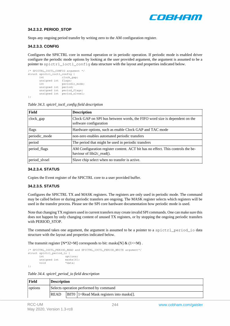
RCC-UMMay 2020, Version 1.3-rc8
244 www.cobham.com/gaisler
34.2.3.2. PERIOD_STOP
Stops any ongoing period transfer by writing zero to the AM configuration register.
34.2.3.3. CONFIG
Configures the SPICTRL core in normal operation or in periodic operation. If periodic mode is enabled driverconfigure the periodic mode options by looking at the user provided argument, the argument is assumed to be apointer to spictrl_ioctl_config data structure with the layout and properties indicated below.
/* SPICTRL_IOCTL_CONFIG argument */struct spictrl_ioctl_config { int clock_gap; unsigned int flags; int periodic_mode; unsigned int period; unsigned int period_flags; unsigned int period_slvsel;};
Table 34.3. spictrl_ioctl_config field description
Field Description
clock_gap Clock GAP on SPI bus between words, the FIFO word size is dependent on thesoftware configuration
flags Hardware options, such as enable Clock GAP and TAC mode
periodic_mode non-zero enables automated periodic transfers
period The period that might be used in periodic transfers
period_flags AM Configuration register content. ACT bit has no effect. This controls the be-haviour of libi2c_read().
period_slvsel Slave chip select when no transfer is active.
34.2.3.4. STATUS
Copies the Event register of the SPICTRL core to a user provided buffer.
34.2.3.5. STATUS
Configures the SPICTRL TX and MASK registers. The registers are only used in periodic mode. The commandmay be called before or during periodic transfers are ongoing. The MASK register selects which registers will beused in the transfer process. Please see the SPI core hardware documentation how periodic mode is used.
Note that changing TX registers used in current transfers may create invalid SPI commands. One can make sure thisdoes not happen by only changing content of unused TX registers, or by stopping the ongoing periodic transferswith PERIOD_STOP.
The command takes one argument, the argument is assumed to be a pointer to a spictrl_period_io datastructure with the layout and properties indicated below.
The transmit register [N*32+M] corresponds to bit: masks[N] & (1<<M) .
/* SPICTRL_IOCTL_PERIOD_READ and SPICTRL_IOCTL_PERIOD_WRITE argument*/struct spictrl_period_io { int options; unsigned int masks[4]; void *data;};
Table 34.4. spictrl_period_io field description
Field Description
Selects operation performed by commandoptions
READ BIT0 1=Read Mask registers into masks[].
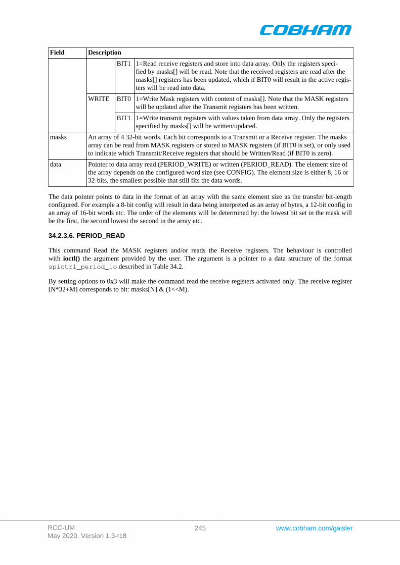
RCC-UMMay 2020, Version 1.3-rc8
245 www.cobham.com/gaisler
Field Description
BIT1 1=Read receive registers and store into data array. Only the registers speci-fied by masks[] will be read. Note that the received registers are read after themasks[] registers has been updated, which if BIT0 will result in the active regis-ters will be read into data.
BIT0 1=Write Mask registers with content of masks[]. Note that the MASK registerswill be updated after the Transmit registers has been written.
WRITE
BIT1 1=Write transmit registers with values taken from data array. Only the registersspecified by masks[] will be written/updated.
masks An array of 4 32-bit words. Each bit corresponds to a Transmit or a Receive register. The masksarray can be read from MASK registers or stored to MASK registers (if BIT0 is set), or only usedto indicate which Transmit/Receive registers that should be Written/Read (if BIT0 is zero).
data Pointer to data array read (PERIOD_WRITE) or written (PERIOD_READ). The element size ofthe array depends on the configured word size (see CONFIG). The element size is either 8, 16 or32-bits, the smallest possible that still fits the data words.
The data pointer points to data in the format of an array with the same element size as the transfer bit-lengthconfigured. For example a 8-bit config will result in data being interpreted as an array of bytes, a 12-bit config inan array of 16-bit words etc. The order of the elements will be determined by: the lowest bit set in the mask willbe the first, the second lowest the second in the array etc.
34.2.3.6. PERIOD_READ
This command Read the MASK registers and/or reads the Receive registers. The behaviour is controlledwith ioctl() the argument provided by the user. The argument is a pointer to a data structure of the formatspictrl_period_io described in Table 34.2.
By setting options to 0x3 will make the command read the receive registers activated only. The receive register[N*32+M] corresponds to bit: masks[N] & (1<<M).
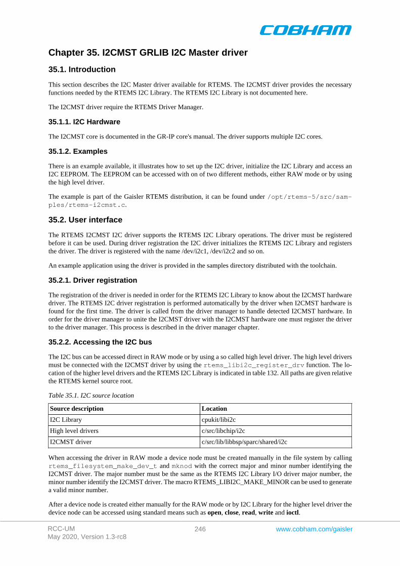
RCC-UMMay 2020, Version 1.3-rc8
246 www.cobham.com/gaisler
Chapter 35. I2CMST GRLIB I2C Master driver
35.1. Introduction
This section describes the I2C Master driver available for RTEMS. The I2CMST driver provides the necessaryfunctions needed by the RTEMS I2C Library. The RTEMS I2C Library is not documented here.
The I2CMST driver require the RTEMS Driver Manager.
35.1.1. I2C Hardware
The I2CMST core is documented in the GR-IP core's manual. The driver supports multiple I2C cores.
35.1.2. Examples
There is an example available, it illustrates how to set up the I2C driver, initialize the I2C Library and access anI2C EEPROM. The EEPROM can be accessed with on of two different methods, either RAW mode or by usingthe high level driver.
The example is part of the Gaisler RTEMS distribution, it can be found under /opt/rtems-5/src/sam-ples/rtems-i2cmst.c.
35.2. User interface
The RTEMS I2CMST I2C driver supports the RTEMS I2C Library operations. The driver must be registeredbefore it can be used. During driver registration the I2C driver initializes the RTEMS I2C Library and registersthe driver. The driver is registered with the name /dev/i2c1, /dev/i2c2 and so on.
An example application using the driver is provided in the samples directory distributed with the toolchain.
35.2.1. Driver registration
The registration of the driver is needed in order for the RTEMS I2C Library to know about the I2CMST hardwaredriver. The RTEMS I2C driver registration is performed automatically by the driver when I2CMST hardware isfound for the first time. The driver is called from the driver manager to handle detected I2CMST hardware. Inorder for the driver manager to unite the I2CMST driver with the I2CMST hardware one must register the driverto the driver manager. This process is described in the driver manager chapter.
35.2.2. Accessing the I2C bus
The I2C bus can be accessed direct in RAW mode or by using a so called high level driver. The high level driversmust be connected with the I2CMST driver by using the rtems_libi2c_register_drv function. The lo-cation of the higher level drivers and the RTEMS I2C Library is indicated in table 132. All paths are given relativethe RTEMS kernel source root.
Table 35.1. I2C source location
Source description Location
I2C Library cpukit/libi2c
High level drivers c/src/libchip/i2c
I2CMST driver c/src/lib/libbsp/sparc/shared/i2c
When accessing the driver in RAW mode a device node must be created manually in the file system by callingrtems_filesystem_make_dev_t and mknod with the correct major and minor number identifying theI2CMST driver. The major number must be the same as the RTEMS I2C Library I/O driver major number, theminor number identify the I2CMST driver. The macro RTEMS_LIBI2C_MAKE_MINOR can be used to generatea valid minor number.
After a device node is created either manually for the RAW mode or by I2C Library for the higher level driver thedevice node can be accessed using standard means such as open, close, read, write and ioctl.
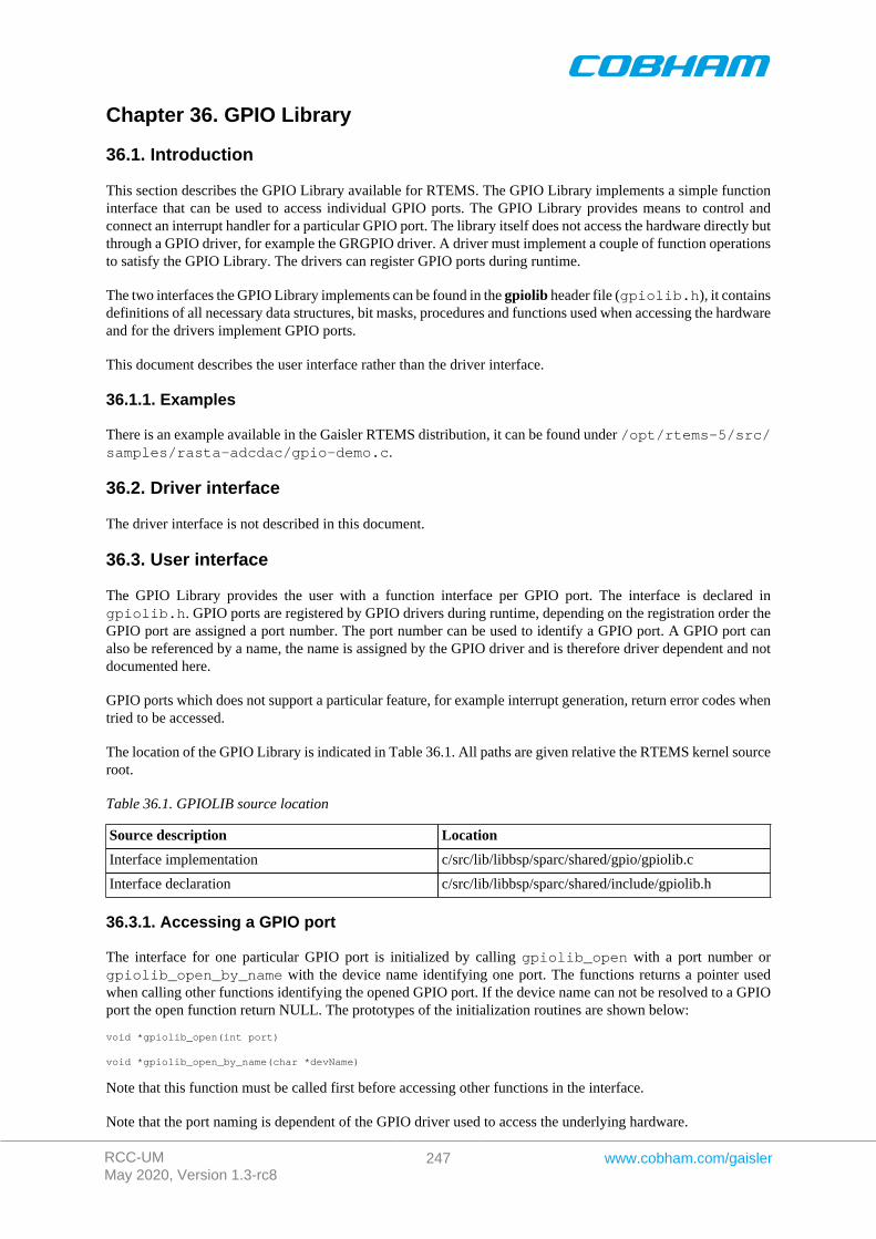
RCC-UMMay 2020, Version 1.3-rc8
247 www.cobham.com/gaisler
Chapter 36. GPIO Library
36.1. Introduction
This section describes the GPIO Library available for RTEMS. The GPIO Library implements a simple functioninterface that can be used to access individual GPIO ports. The GPIO Library provides means to control andconnect an interrupt handler for a particular GPIO port. The library itself does not access the hardware directly butthrough a GPIO driver, for example the GRGPIO driver. A driver must implement a couple of function operationsto satisfy the GPIO Library. The drivers can register GPIO ports during runtime.
The two interfaces the GPIO Library implements can be found in the gpiolib header file (gpiolib.h), it containsdefinitions of all necessary data structures, bit masks, procedures and functions used when accessing the hardwareand for the drivers implement GPIO ports.
This document describes the user interface rather than the driver interface.
36.1.1. Examples
There is an example available in the Gaisler RTEMS distribution, it can be found under /opt/rtems-5/src/samples/rasta-adcdac/gpio-demo.c.
36.2. Driver interface
The driver interface is not described in this document.
36.3. User interface
The GPIO Library provides the user with a function interface per GPIO port. The interface is declared ingpiolib.h. GPIO ports are registered by GPIO drivers during runtime, depending on the registration order theGPIO port are assigned a port number. The port number can be used to identify a GPIO port. A GPIO port canalso be referenced by a name, the name is assigned by the GPIO driver and is therefore driver dependent and notdocumented here.
GPIO ports which does not support a particular feature, for example interrupt generation, return error codes whentried to be accessed.
The location of the GPIO Library is indicated in Table 36.1. All paths are given relative the RTEMS kernel sourceroot.
Table 36.1. GPIOLIB source location
Source description Location
Interface implementation c/src/lib/libbsp/sparc/shared/gpio/gpiolib.c
Interface declaration c/src/lib/libbsp/sparc/shared/include/gpiolib.h
36.3.1. Accessing a GPIO port
The interface for one particular GPIO port is initialized by calling gpiolib_open with a port number orgpiolib_open_by_name with the device name identifying one port. The functions returns a pointer usedwhen calling other functions identifying the opened GPIO port. If the device name can not be resolved to a GPIOport the open function return NULL. The prototypes of the initialization routines are shown below:
void *gpiolib_open(int port)
void *gpiolib_open_by_name(char *devName)
Note that this function must be called first before accessing other functions in the interface.
Note that the port naming is dependent of the GPIO driver used to access the underlying hardware.
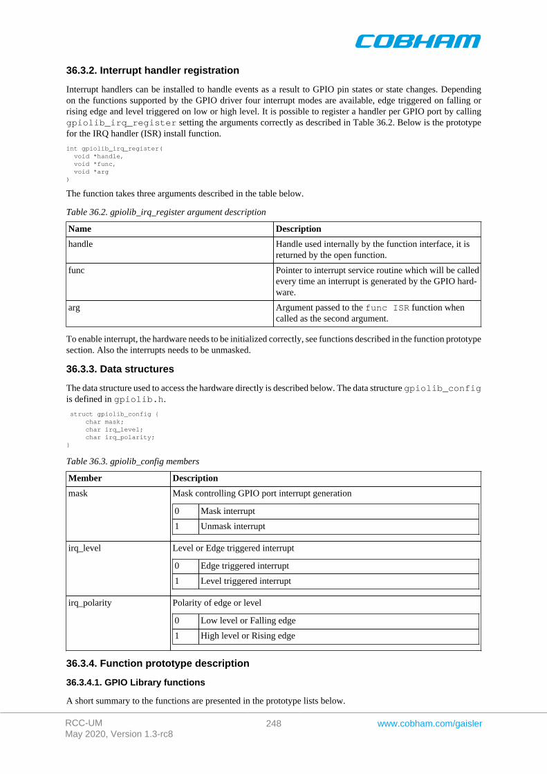
RCC-UMMay 2020, Version 1.3-rc8
248 www.cobham.com/gaisler
36.3.2. Interrupt handler registration
Interrupt handlers can be installed to handle events as a result to GPIO pin states or state changes. Dependingon the functions supported by the GPIO driver four interrupt modes are available, edge triggered on falling orrising edge and level triggered on low or high level. It is possible to register a handler per GPIO port by callinggpiolib_irq_register setting the arguments correctly as described in Table 36.2. Below is the prototypefor the IRQ handler (ISR) install function.
int gpiolib_irq_register( void *handle, void *func, void *arg)
The function takes three arguments described in the table below.
Table 36.2. gpiolib_irq_register argument description
Name Description
handle Handle used internally by the function interface, it isreturned by the open function.
func Pointer to interrupt service routine which will be calledevery time an interrupt is generated by the GPIO hard-ware.
arg Argument passed to the func ISR function whencalled as the second argument.
To enable interrupt, the hardware needs to be initialized correctly, see functions described in the function prototypesection. Also the interrupts needs to be unmasked.
36.3.3. Data structures
The data structure used to access the hardware directly is described below. The data structure gpiolib_configis defined in gpiolib.h.
struct gpiolib_config { char mask; char irq_level; char irq_polarity;}
Table 36.3. gpiolib_config members
Member Description
mask Mask controlling GPIO port interrupt generation
0 Mask interrupt
1 Unmask interrupt
irq_level Level or Edge triggered interrupt
0 Edge triggered interrupt
1 Level triggered interrupt
irq_polarity Polarity of edge or level
0 Low level or Falling edge
1 High level or Rising edge
36.3.4. Function prototype description
36.3.4.1. GPIO Library functions
A short summary to the functions are presented in the prototype lists below.
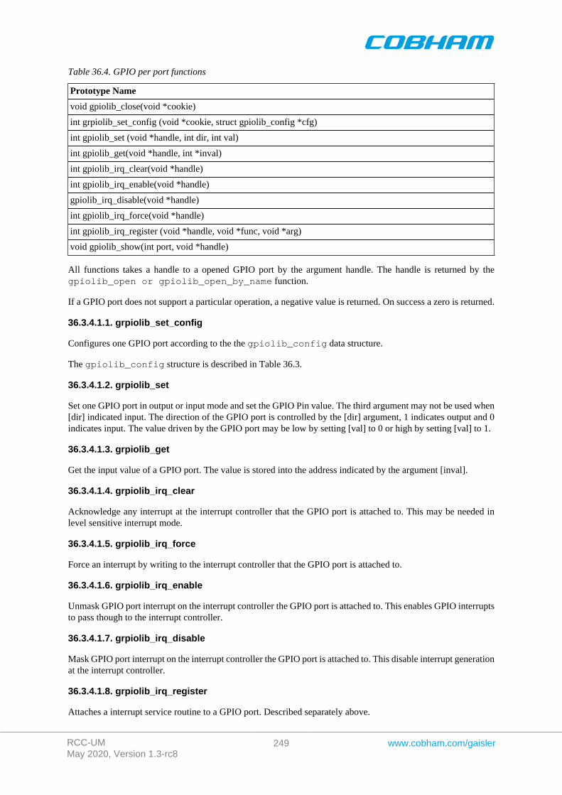
RCC-UMMay 2020, Version 1.3-rc8
249 www.cobham.com/gaisler
Table 36.4. GPIO per port functions
Prototype Name
void gpiolib_close(void *cookie)
int grpiolib_set_config (void *cookie, struct gpiolib_config *cfg)
int gpiolib_set (void *handle, int dir, int val)
int gpiolib_get(void *handle, int *inval)
int gpiolib_irq_clear(void *handle)
int gpiolib_irq_enable(void *handle)
gpiolib_irq_disable(void *handle)
int gpiolib_irq_force(void *handle)
int gpiolib_irq_register (void *handle, void *func, void *arg)
void gpiolib_show(int port, void *handle)
All functions takes a handle to a opened GPIO port by the argument handle. The handle is returned by thegpiolib_open or gpiolib_open_by_name function.
If a GPIO port does not support a particular operation, a negative value is returned. On success a zero is returned.
36.3.4.1.1. grpiolib_set_config
Configures one GPIO port according to the the gpiolib_config data structure.
The gpiolib_config structure is described in Table 36.3.
36.3.4.1.2. grpiolib_set
Set one GPIO port in output or input mode and set the GPIO Pin value. The third argument may not be used when[dir] indicated input. The direction of the GPIO port is controlled by the [dir] argument, 1 indicates output and 0indicates input. The value driven by the GPIO port may be low by setting [val] to 0 or high by setting [val] to 1.
36.3.4.1.3. grpiolib_get
Get the input value of a GPIO port. The value is stored into the address indicated by the argument [inval].
36.3.4.1.4. grpiolib_irq_clear
Acknowledge any interrupt at the interrupt controller that the GPIO port is attached to. This may be needed inlevel sensitive interrupt mode.
36.3.4.1.5. grpiolib_irq_force
Force an interrupt by writing to the interrupt controller that the GPIO port is attached to.
36.3.4.1.6. grpiolib_irq_enable
Unmask GPIO port interrupt on the interrupt controller the GPIO port is attached to. This enables GPIO interruptsto pass though to the interrupt controller.
36.3.4.1.7. grpiolib_irq_disable
Mask GPIO port interrupt on the interrupt controller the GPIO port is attached to. This disable interrupt generationat the interrupt controller.
36.3.4.1.8. grpiolib_irq_register
Attaches a interrupt service routine to a GPIO port. Described separately above.
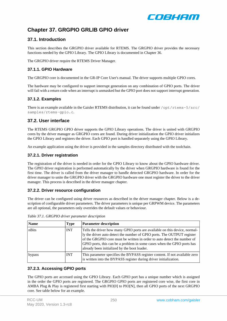
RCC-UMMay 2020, Version 1.3-rc8
250 www.cobham.com/gaisler
Chapter 37. GRGPIO GRLIB GPIO driver
37.1. Introduction
This section describes the GRGPIO driver available for RTEMS. The GRGPIO driver provides the necessaryfunctions needed by the GPIO Library. The GPIO Library is documented in Chapter 36.
The GRGPIO driver require the RTEMS Driver Manager.
37.1.1. GPIO Hardware
The GRGPIO core is documented in the GR-IP Core User's manual. The driver supports multiple GPIO cores.
The hardware may be configured to support interrupt generation on any combination of GPIO ports. The driverwill fail with a return code when an interrupt is unmasked but the GPIO port does not support interrupt generation.
37.1.2. Examples
There is an example available in the Gaisler RTEMS distribution, it can be found under /opt/rtems-5/src/samples/rtems-gpio.c.
37.2. User interface
The RTEMS GRGPIO GPIO driver supports the GPIO Library operations. The driver is united with GRGPIOcores by the driver manager as GRGPIO cores are found. During driver initialization the GPIO driver initializesthe GPIO Library and registers the driver. Each GPIO port is handled separately using the GPIO Library.
An example application using the driver is provided in the samples directory distributed with the toolchain.
37.2.1. Driver registration
The registration of the driver is needed in order for the GPIO Library to know about the GPIO hardware driver.The GPIO driver registration is performed automatically by the driver when GRGPIO hardware is found for thefirst time. The driver is called from the driver manager to handle detected GRGPIO hardware. In order for thedriver manager to unite the GRGPIO driver with the GRGPIO hardware one must register the driver to the drivermanager. This process is described in the driver manager chapter.
37.2.2. Driver resource configuration
The driver can be configured using driver resources as described in the driver manager chapter. Below is a de-scription of configurable driver parameters. The driver parameters is unique per GRPWM device. The parametersare all optional, the parameters only overrides the default values or behaviour.
Table 37.1. GRGPIO driver parameter description
Name Type Parameter description
nBits INT Tells the driver how many GPIO ports are available on this device, normal-ly the driver auto detect the number of GPIO ports. The OUTPUT registerof the GRGPIO core must be written in order to auto detect the number ofGPIO ports, this can be a problem in some cases when the GPIO ports hasalready been initialized by the boot loader.
bypass INT This parameter specifies the BYPASS register content. If not available zerois written into the BYPASS register during driver initialization.
37.2.3. Accessing GPIO ports
The GPIO ports are accessed using the GPIO Library. Each GPIO port has a unique number which is assignedin the order the GPIO ports are registered. The GRGPIO GPIO ports are registered core wise, the first core inAMBA Plug & Play is registered first starting with PIO[0] to PIO[N], then all GPIO ports of the next GRGPIOcore. See table below for an example.
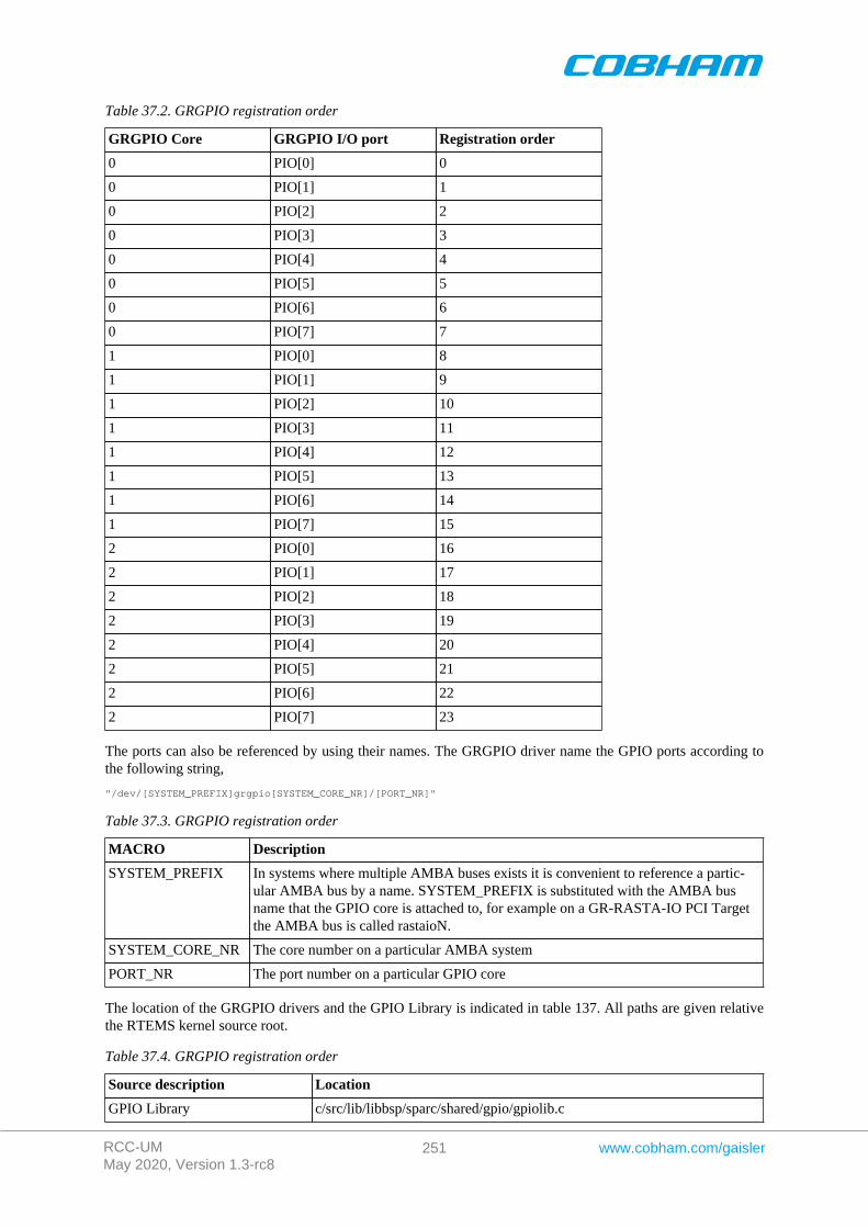
RCC-UMMay 2020, Version 1.3-rc8
251 www.cobham.com/gaisler
Table 37.2. GRGPIO registration order
GRGPIO Core GRGPIO I/O port Registration order
0 PIO[0] 0
0 PIO[1] 1
0 PIO[2] 2
0 PIO[3] 3
0 PIO[4] 4
0 PIO[5] 5
0 PIO[6] 6
0 PIO[7] 7
1 PIO[0] 8
1 PIO[1] 9
1 PIO[2] 10
1 PIO[3] 11
1 PIO[4] 12
1 PIO[5] 13
1 PIO[6] 14
1 PIO[7] 15
2 PIO[0] 16
2 PIO[1] 17
2 PIO[2] 18
2 PIO[3] 19
2 PIO[4] 20
2 PIO[5] 21
2 PIO[6] 22
2 PIO[7] 23
The ports can also be referenced by using their names. The GRGPIO driver name the GPIO ports according tothe following string,
"/dev/[SYSTEM_PREFIX]grgpio[SYSTEM_CORE_NR]/[PORT_NR]"
Table 37.3. GRGPIO registration order
MACRO Description
SYSTEM_PREFIX In systems where multiple AMBA buses exists it is convenient to reference a partic-ular AMBA bus by a name. SYSTEM_PREFIX is substituted with the AMBA busname that the GPIO core is attached to, for example on a GR-RASTA-IO PCI Targetthe AMBA bus is called rastaioN.
SYSTEM_CORE_NR The core number on a particular AMBA system
PORT_NR The port number on a particular GPIO core
The location of the GRGPIO drivers and the GPIO Library is indicated in table 137. All paths are given relativethe RTEMS kernel source root.
Table 37.4. GRGPIO registration order
Source description Location
GPIO Library c/src/lib/libbsp/sparc/shared/gpio/gpiolib.c

RCC-UMMay 2020, Version 1.3-rc8
252 www.cobham.com/gaisler
Source description Location
GRGPIO driver c/src/lib/libbsp/sparc/shared/gpio/grgpio.c
RCC-UMMay 2020, Version 1.3-rc8
253 www.cobham.com/gaisler
Chapter 38. GRADCDAC GRLIB ADC/DAC driver
38.1. Introduction
This section describes the GRADCDAC driver available for RTEMS. The GRADCDAC driver provides a functioninterface to the user with the ability to access the hardware directly. User applications include the gradcdacheader file (gradcdac.h) which contains definitions of all necessary data structures, bit masks, procedures andfunctions used when accessing the hardware.
The GRADCDAC driver require the RTEMS Driver Manager.
38.1.1. ADC/DAC Hardware
The GRADCDAC core is documented in the GR-IP Core User's manual. The driver supports multiple GRADC-DAC cores.
The GRADCADC core has two different IRQs, one ADC interrupt and one DAC interrupt.
38.1.2. Examples
There is an example available in the Gaisler RTEMS distribution, it can be found under /opt/rtems-5/src/samples/rasta-adcdac/gradcdac-demo.c.
38.2. User interface
The RTEMS GRADCDAC ADC/DAC driver provides the user with a function interface. The interface is declaredin gradcdac.h. The driver is united with GRADCDAC cores by the driver manager as GRADCDAC cores arefound. During driver initialization the ADCDAC driver initializes the ADC/DAC hardware to an initial state, forthat point and onwards the function interface can be used to access the ADC/DAC hardware registers.
An example application using the driver is provided in the samples/rasta-adcdac directory distributedwith the toolchain.
The location of the GRADCDAC driver is indicated in Table 38.1. All paths are given relative the RTEMS kernelsource root.
Table 38.1. GRGPIO registration order
Source description Location
GREDCDAC driver c/src/lib/libbsp/sparc/shared/analog/gradcdac.c
Driver Interface c/src/lib/libbsp/sparc/shared/include/gradcdac.h
38.2.1. Driver registration
The GRADCDAC is registered to the Driver Manager layer by setting the correct define in the project set up, seeDriver Manager section.
The driver does not implement a I/O driver interface so the GRADCDAC does not register itself as a I/O driver,it implements a custom function interface that is available to the user.
38.2.2. Driver resource configuration
The driver does not support configurable resource parameters.
38.2.3. Accessing ADC/DAC
The Interface for one particular ADC/DAC core is initialized by calling gradcdac_open with the device nameidentifying one core. The function returns a pointer used when calling other functions identifying the opened ADC/
RCC-UMMay 2020, Version 1.3-rc8
254 www.cobham.com/gaisler
DAC core. If the device name can not be resolved to a ADC/DAC core the open function return NULL. Theprototype of the initialization routine is shown below:
void *gradcdac_open(char *devname)
Note that this function must be called first before accessing other functions in the interface.
The GRADCDAC cores are be referenced by using their names, the names are generated according to the followingstring,
"/dev/[SYSTEM_PREFIX]gradcdac[SYSTEM_CORE_NR]"
Table 38.2. GRADCDAC core naming
MACRO Description
SYSTEM_PREFIX In systems where multiple AMBA buses exists it is convenient to reference aparticular AMBA bus by a name. SYSTEM_PREFIX is substituted with theAMBA bus name that the ADC/DAC core is attached to, for example on a GR-RASTA-ADCDAC PCI Target the AMBA bus is called rastaadcdacN. Thisstring is empty when the GRADCDAC is on the system AMBA bus.
SYSTEM_CORE_NR The core number on a particular AMBA system.
38.2.4. Interrupt handler registration
Interrupt handlers can be installed to handle events as a result to AD/DA conversions. It is possible to registera handler for AD and or DA conversions by setting the adc argument appropriately as described in Table 38.3.Below is the prototype for the IRQ handler (ISR) install function.
int gradcdac_install_irq_handler( void *cookie, int adc, void (*isr)(int irq, void *arg), void *arg)
The function takes three arguments described in the table below.
Table 38.3. gradcdac_install_irq_handler argument description
Name Description
cookie Handle used internally by the function interface, it is returned by the open function.
adcValue Function
1 Register handler to ADC interrupt
2 Register handler to DAC interrupt
3 Register to both ADC and DAC interrupts
isr Pointer to interrupt service routine which will be called every time an interrupt is generatedby the ADC/DAC hardware.
arg Argument passed to the isr function when called as the second argument.
To enable interrupt the hardware needs to be initialized correctly see functions described in the function prototypesection. Also the AD and or DA interrupts needs to be unmasked.
38.2.5. Data structures
The data structure used to access the hardware directly is described below. The data structure gradcdac_regsis defined in gradcdac.h.
struct gradcdac_regs { volatile unsigned int config; volatile unsigned int status; int unused0[2];
RCC-UMMay 2020, Version 1.3-rc8
255 www.cobham.com/gaisler
volatile unsigned int adc_din; volatile unsigned int dac_dout; int unused1[2]; volatile unsigned int adrin; volatile unsigned int adrout; volatile unsigned int adrdir; int unused2[1]; volatile unsigned int data_in; volatile unsigned int data_out; volatile unsigned int data_dir;}
The gradcdac_config data structure is used to read and write the ADC/DAC controllers configuration reg-ister.
struct gradcdac_config { unsigned char dac_ws; char wr_pol; unsigned char dac_dw; unsigned char adc_ws; char rc_pol; unsigned char cs_mode; char cs_pol; char ready_mode; char ready_pol; char trigg_pol; unsigned char trigg_mode; unsigned char adc_dw;};
Table 38.4. gradcdac_config member and ADCONF reg definition
Member Member type ADCONF Bit start Description
dac_ws 5-bit int 19 Number of DAC waitstates.
wr_pol Boolean 18 Polarity of DAC writestrobe
0 Active low
1 Active High
dac_dw 2-bit selection 16 DAC data width
0 none
1 8-bit ADDATA[0:7]
2 16-bit ADDATA[0:15]
3 none/spare
adc_ws 5-bit int 11 Number of DAC waitstates.
rc_pol Boolean 10 Polarity of ADC read con-vert
0 Active low read
1 Active high read
cs_mode 2-bit selection 8 Mode of ADC chip selectasserted ...
0 during conversionand read phases
1 during conversionphase

RCC-UMMay 2020, Version 1.3-rc8
256 www.cobham.com/gaisler
Member Member type ADCONF Bit start Description
2 during read phase
3 continuously dur-ing both phases
cs_pol Boolean 7 Polarity of ADC chip se-lect
0 Active low
1 Active high
ready_mode Boolean 6 Mode of ADC ready
0 Falling edge
1 Rising edge
ready_pol Boolean 5 Polarity of ADC ready
0 unused, open-loop
1 used, with time-out
trigg_pol Boolean 4 Polarity of ADC triggers
0 falling edge
1 rising edge
trigg_mode 2-bit selection 2 ADC trigger source
0 none
1 ADTrig
2 32-bit Timer 1
3 32-bit Timer 2
adc_dw 2-bit selection 0 ADC data width
0 none
1 8-bit ADDA-TA[7:0]
2 16-bit ADDA-TA[15:0]
3 none/spare
38.2.6. Function prototype description
38.2.6.1. General ADC/DAC functions
A short summary to the functions are presented in the prototype lists below.
Table 38.5. General ADC/DAC functions
Prototype Name
void gradcdac_set_config (void *cookie, struct gradcdac_config *cfg)
void gradcdac_get_config (void *cookie, struct gradcdac_config *cfg)
RCC-UMMay 2020, Version 1.3-rc8
257 www.cobham.com/gaisler
Prototype Name
void gradcdac_set_cfg (void *cookie, unsigned int config)
unsigned int gradcdac_get_cfg(void *cookie)
unsigned int gradcdac_get_status(void *cookie)
void gradcdac_adc_convert_start(void *cookie)
unsigned int gradcdac_get_adrinput (void *cookie)
unsigned int gradcdac_get_adroutput (void *cookie)
void gradcdac_set_adroutput (void *cookie, unsigned int output)
unsigned int gradcdac_get_adrdir(void *cookie)
void gradcdac_set_adrdir (void *cookie, unsigned int dir)
unsigned int gradcdac_get_datainput (void *cookie, void)
unsigned int gradcdac_get_dataoutput (void *cookie, void)
void gradcdac_set_dataoutput (void *cookie, unsigned int output)
unsigned int gradcdac_get_datadir (void *cookie, void)
void gradcdac_set_datadir (void *cookie, unsigned int dir)
All functions takes a handle to the ADC/DAC core by the argument cookie. The handle is returned by thegradcdac_open function.
38.2.6.1.1. gradcdac_set_config
Writes the configuration register of the ADC / DAC controller from the gradcdac_config data structure.
The gradcdac_config structure is described in Table 38.4.
38.2.6.1.2. gradcdac_get_config
Reads the configuration from the controller's configuration register and converts into the data structuregradcdac_config pointed to by the user provided [cfg] argument.
The gradcdac_config structure is described in Table 38.4.
38.2.6.1.3. gradcdac_set_cfg
Sets the configuration register directly.
The bits of the ADCONF configuration register are described in Table 38.4.
38.2.6.1.4. gradcdac_get_cfg
Returns the current configuration register value as it is.
The bits of the ADCONF configuration register are described in Table 38.4.
38.2.6.1.5. gradcdac_get_status
Returns the current ADC / DAC controller's status register value.
38.2.6.1.6. gradcdac_get_adrinput
Returns the current address input register value.
38.2.6.1.7. gradcdac_get_adroutput
Returns the current address output register value.
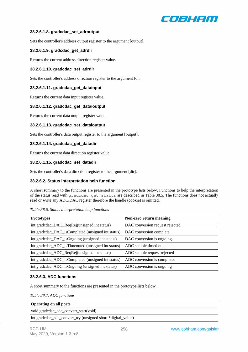
RCC-UMMay 2020, Version 1.3-rc8
258 www.cobham.com/gaisler
38.2.6.1.8. gradcdac_set_adroutput
Sets the controller's address output register to the argument [output].
38.2.6.1.9. gradcdac_get_adrdir
Returns the current address direction register value.
38.2.6.1.10. gradcdac_set_adrdir
Sets the controller's address direction register to the argument [dir].
38.2.6.1.11. gradcdac_get_datainput
Returns the current data input register value.
38.2.6.1.12. gradcdac_get_dataioutput
Returns the current data output register value.
38.2.6.1.13. gradcdac_set_dataioutput
Sets the controller's data output register to the argument [output].
38.2.6.1.14. gradcdac_get_datadir
Returns the current data direction register value.
38.2.6.1.15. gradcdac_set_datadir
Sets the controller's data direction register to the argument [dir].
38.2.6.2. Status interpretation help function
A short summary to the functions are presented in the prototype lists below. Functions to help the interpretationof the status read with gradcdac_get_status are described in Table 38.5. The functions does not actuallyread or write any ADC/DAC register therefore the handle (cookie) is omitted.
Table 38.6. Status interpretation help functions
Prototypes Non-zero return meaning
int gradcdac_DAC_ReqRej(unsigned int status) DAC conversion request rejected
int gradcdac_DAC_isCompleted (unsigned int status) DAC conversion complete
int gradcdac_DAC_isOngoing (unsigned int status) DAC conversion is ongoing
int gradcdac_ADC_isTimeouted (unsigned int status) ADC sample timed out
int gradcdac_ADC_ReqRej(unsigned int status) ADC sample request rejected
int gradcdac_ADC_isCompleted (unsigned int status) ADC conversion is completed
int gradcdac_ADC_isOngoing (unsigned int status) ADC conversion is ongoing
38.2.6.3. ADC functions
A short summary to the functions are presented in the prototype lists below.
Table 38.7. ADC functions
Operating on all ports
void gradcdac_adc_convert_start(void)
int gradcdac_adc_convert_try (unsigned short *digital_value)
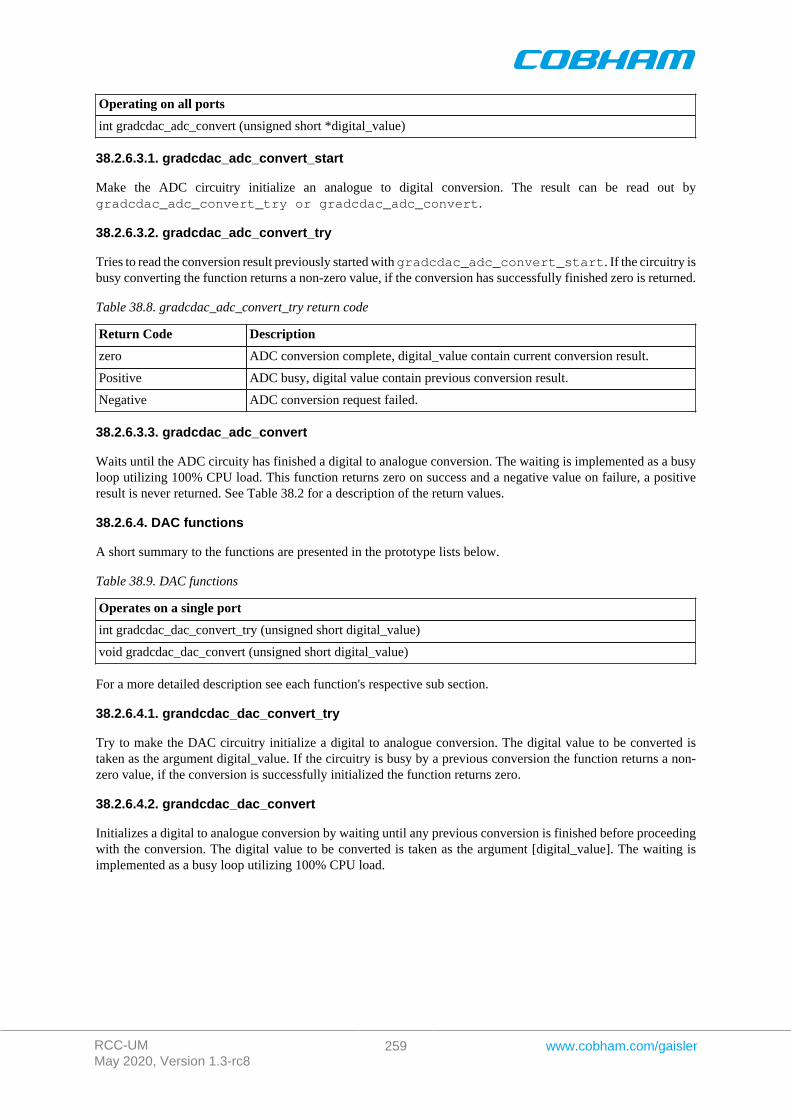
RCC-UMMay 2020, Version 1.3-rc8
259 www.cobham.com/gaisler
Operating on all ports
int gradcdac_adc_convert (unsigned short *digital_value)
38.2.6.3.1. gradcdac_adc_convert_start
Make the ADC circuitry initialize an analogue to digital conversion. The result can be read out bygradcdac_adc_convert_try or gradcdac_adc_convert.
38.2.6.3.2. gradcdac_adc_convert_try
Tries to read the conversion result previously started with gradcdac_adc_convert_start. If the circuitry isbusy converting the function returns a non-zero value, if the conversion has successfully finished zero is returned.
Table 38.8. gradcdac_adc_convert_try return code
Return Code Description
zero ADC conversion complete, digital_value contain current conversion result.
Positive ADC busy, digital value contain previous conversion result.
Negative ADC conversion request failed.
38.2.6.3.3. gradcdac_adc_convert
Waits until the ADC circuity has finished a digital to analogue conversion. The waiting is implemented as a busyloop utilizing 100% CPU load. This function returns zero on success and a negative value on failure, a positiveresult is never returned. See Table 38.2 for a description of the return values.
38.2.6.4. DAC functions
A short summary to the functions are presented in the prototype lists below.
Table 38.9. DAC functions
Operates on a single port
int gradcdac_dac_convert_try (unsigned short digital_value)
void gradcdac_dac_convert (unsigned short digital_value)
For a more detailed description see each function's respective sub section.
38.2.6.4.1. grandcdac_dac_convert_try
Try to make the DAC circuitry initialize a digital to analogue conversion. The digital value to be converted istaken as the argument digital_value. If the circuitry is busy by a previous conversion the function returns a non-zero value, if the conversion is successfully initialized the function returns zero.
38.2.6.4.2. grandcdac_dac_convert
Initializes a digital to analogue conversion by waiting until any previous conversion is finished before proceedingwith the conversion. The digital value to be converted is taken as the argument [digital_value]. The waiting isimplemented as a busy loop utilizing 100% CPU load.
RCC-UMMay 2020, Version 1.3-rc8
260 www.cobham.com/gaisler
Chapter 39. GRTC GRLIB CCSDS Telecommand driver
39.1. INTRODUCTION
This document is intended as an aid in getting started developing with Aeroflex Gaisler GRLIB GRTC Telecom-mand (TC) core using the driver described in this document. It describes accessing GRTC in a on-chip system andover PCI and SpaceWire. It briefly takes the reader through some of the most important steps in using the driversuch as starting TC communication, configuring the driver and receiving TC frames. The reader is assumed to bewell acquainted with TC and RTEMS.
39.1.1. TC Hardware
See the GRTC core manual. When the GRTC core is accessed over SpaceWire RMAP is used.
39.1.2. Software Driver
The driver provides means for threads to receive TC frames using standard I/O operations. There are two drivers,one that supports GRTC on an on-chip AMBA bus and an AMBA bus accessed over PCI (on a GR-RASTA-TMTCboard for example) and one driver that supports accessing the GRTC over SpaceWire.
39.1.2.1. GRTC over SpaceWire
The SpaceWire capable GRTC driver introduces some limitations listed below:
1. RAW mode is not supported (the read call)2. The GRTC DMA area accessed over SpaceWire is cached in RAM close to the CPU. The cached DMA
area is equal in length to the GRTC DMA area. The cache is synchronized every time the user enters thereceive function.
3. A field named dma_partition has been added to the grtc_ioc_buf_params structure identifyingthe partition used when allocating the DMA memory on the SpaceWire node. The custom_buffer optionis still available, it determines where the cached area is located.
39.2. User interface
The RTEMS GRTC driver supports the standard accesses to file descriptors such as open, read and ioctl. Userapplications include the grtc driver's header file which contains definitions of all necessary data structures andbit masks used when accessing the driver.
The driver enables the user to configure the hardware and to receive TC frames. The driver can be operated in twodifferent modes either in RAW mode giving the user the possibility to read the DMA area it self using the readcall or in FRAME mode where the driver handles basic frame parsing by looking at the header length field and thecontrol bytes from the TC core. In the FRAME mode the allocation of TC frames is handled by the user, emptyframes are given to the driver that puts data and header of received TC frames into the user allocated frames ina two step process. In the first step the user provides the driver with unused frames queued in an driver internalqueue, the second step is when the user retrieve the frames containing a complete received frame, filler is notcopied in FRAME mode.
Note that RAW mode is not supported when operating the GRTC over SpaceWire.
39.2.1. Driver registration
The registration of the driver is crucial for threads to be able to access the driver using standard means, such asopen. The function grtc_register whose prototype is provided in grtc.h is used for registering the driver. Itreturns 0 on success and 1 on failure. A typical register call from the LEON3 Init task:
if ( grtc_register(&amba_conf) ) printf(“GRTC register Failed\n”);
39.2.2. Opening the device
Opening the device enables the user to access the hardware of a certain GRTC device. The driver is used for allGRTC cores available. The cores are separated by assigning each core a unique name and a number called [minor].The name is given during the opening of the driver. The first three names are printed out:
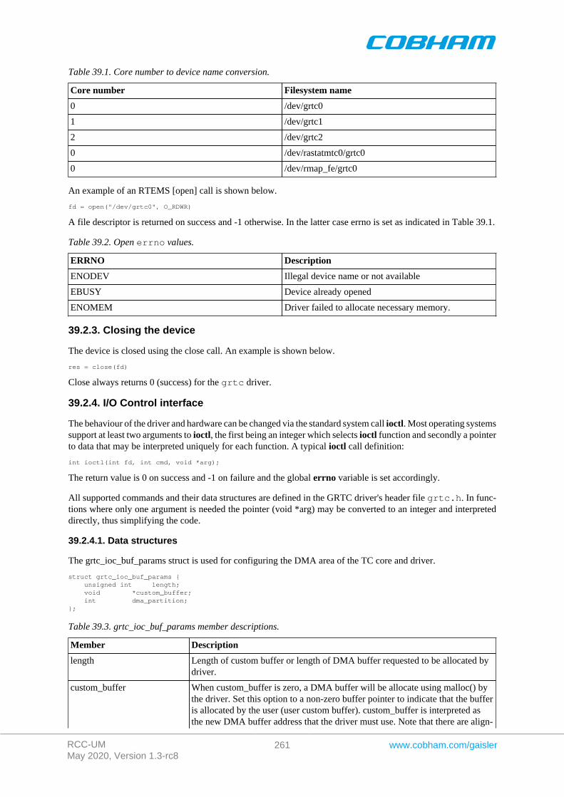
RCC-UMMay 2020, Version 1.3-rc8
261 www.cobham.com/gaisler
Table 39.1. Core number to device name conversion.
Core number Filesystem name
0 /dev/grtc0
1 /dev/grtc1
2 /dev/grtc2
0 /dev/rastatmtc0/grtc0
0 /dev/rmap_fe/grtc0
An example of an RTEMS [open] call is shown below.
fd = open("/dev/grtc0", O_RDWR)
A file descriptor is returned on success and -1 otherwise. In the latter case errno is set as indicated in Table 39.1.
Table 39.2. Open errno values.
ERRNO Description
ENODEV Illegal device name or not available
EBUSY Device already opened
ENOMEM Driver failed to allocate necessary memory.
39.2.3. Closing the device
The device is closed using the close call. An example is shown below.
res = close(fd)
Close always returns 0 (success) for the grtc driver.
39.2.4. I/O Control interface
The behaviour of the driver and hardware can be changed via the standard system call ioctl. Most operating systemssupport at least two arguments to ioctl, the first being an integer which selects ioctl function and secondly a pointerto data that may be interpreted uniquely for each function. A typical ioctl call definition:
int ioctl(int fd, int cmd, void *arg);
The return value is 0 on success and -1 on failure and the global errno variable is set accordingly.
All supported commands and their data structures are defined in the GRTC driver's header file grtc.h. In func-tions where only one argument is needed the pointer (void *arg) may be converted to an integer and interpreteddirectly, thus simplifying the code.
39.2.4.1. Data structures
The grtc_ioc_buf_params struct is used for configuring the DMA area of the TC core and driver.
struct grtc_ioc_buf_params { unsigned int length; void *custom_buffer; int dma_partition;};
Table 39.3. grtc_ioc_buf_params member descriptions.
Member Description
length Length of custom buffer or length of DMA buffer requested to be allocated bydriver.
custom_buffer When custom_buffer is zero, a DMA buffer will be allocate using malloc() bythe driver. Set this option to a non-zero buffer pointer to indicate that the bufferis allocated by the user (user custom buffer). custom_buffer is interpreted asthe new DMA buffer address that the driver must use. Note that there are align-
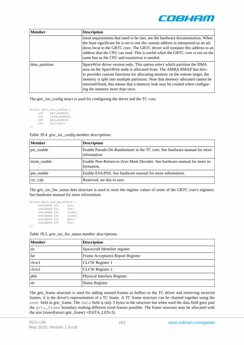
RCC-UMMay 2020, Version 1.3-rc8
262 www.cobham.com/gaisler
Member Description
ment requirements that need to be met, see the hardware documentation. Whenthe least significant bit is set to one the custom address is interpreted as an ad-dress local to the GRTC core. The GRTC driver will translate this address to anaddress that the CPU can read. This is useful when the GRTC core is not on thesame bus as the CPU and translation is needed.
dma_partition SpaceWire driver version only. This option select which partition the DMAarea on the SpaceWire node is allocated from. The AMBA RMAP bus driv-er provides custom functions for allocating memory on the remote target, thememory is split into multiple partitions. Note that memory allocated cannot bereturned/freed, this means that a memory leak may be created when configur-ing the memory more than once.
The grtc_ioc_config struct is used for configuring the driver and the TC core.
struct grtc_ioc_config { int psr_enable; int nrzm_enable; int pss_enable; int crc_calc;};
Table 39.4. grtc_ioc_config member descriptions.
Member Description
psr_enable Enable Pseudo-De-Randomizer in the TC core. See hardware manual for moreinformation.
nrzm_enable Enable Non-Return-to-Zero Mark Decoder. See hardware manual for more in-formation.
pss_enable Enable ESA/PSS. See hardware manual for more information.
crc_calc Reserved, set this to zero
The grtc_ioc_hw_status data structure is used to store the register values of some of the GRTC core's registers.See hardware manual for more information.
struct grtc_ioc_hw_status { unsigned int sir; unsigned int far; unsigned int clcw1; unsigned int clcw2; unsigned int phir; unsigned int str;};
Table 39.5. grtc_ioc_hw_status member descriptions.
Member Description
sir Spacecraft Identifier register
far Frame Acceptance Report Register
clcw1 CLCW Register 1
clcw2 CLCW Register 2
phir Physical Interface Register
str Status Register
The grtc_frame structure is used for adding unused frames as buffers to the TC driver and retrieving receivedframes, it is the driver's representation of a TC frame. A TC frame structure can be chained together using thenext field in grtc_frame. The data field is only 3 bytes in the structure but when used the data field goes pastthe grtc_frame boundary making different sized frames possible. The frame structure may be allocated withthe size [sizeof(struct grtc_frame) +DATA_LEN-3].
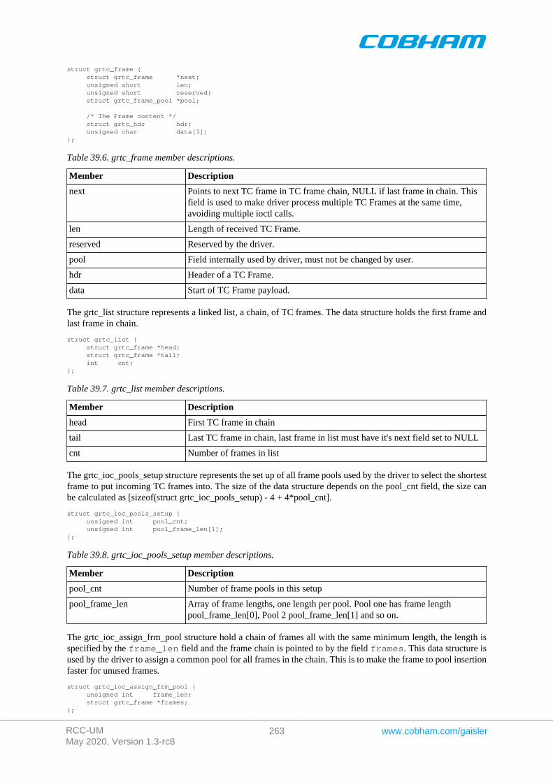
RCC-UMMay 2020, Version 1.3-rc8
263 www.cobham.com/gaisler
struct grtc_frame { struct grtc_frame *next; unsigned short len; unsigned short reserved; struct grtc_frame_pool *pool;
/* The Frame content */ struct grtc_hdr hdr; unsigned char data[3];};
Table 39.6. grtc_frame member descriptions.
Member Description
next Points to next TC frame in TC frame chain, NULL if last frame in chain. Thisfield is used to make driver process multiple TC Frames at the same time,avoiding multiple ioctl calls.
len Length of received TC Frame.
reserved Reserved by the driver.
pool Field internally used by driver, must not be changed by user.
hdr Header of a TC Frame.
data Start of TC Frame payload.
The grtc_list structure represents a linked list, a chain, of TC frames. The data structure holds the first frame andlast frame in chain.
struct grtc_list { struct grtc_frame *head; struct grtc_frame *tail; int cnt;};
Table 39.7. grtc_list member descriptions.
Member Description
head First TC frame in chain
tail Last TC frame in chain, last frame in list must have it's next field set to NULL
cnt Number of frames in list
The grtc_ioc_pools_setup structure represents the set up of all frame pools used by the driver to select the shortestframe to put incoming TC frames into. The size of the data structure depends on the pool_cnt field, the size canbe calculated as [sizeof(struct grtc_ioc_pools_setup) - 4 + 4*pool_cnt].
struct grtc_ioc_pools_setup { unsigned int pool_cnt; unsigned int pool_frame_len[1];};
Table 39.8. grtc_ioc_pools_setup member descriptions.
Member Description
pool_cnt Number of frame pools in this setup
pool_frame_len Array of frame lengths, one length per pool. Pool one has frame lengthpool_frame_len[0], Pool 2 pool_frame_len[1] and so on.
The grtc_ioc_assign_frm_pool structure hold a chain of frames all with the same minimum length, the length isspecified by the frame_len field and the frame chain is pointed to by the field frames. This data structure isused by the driver to assign a common pool for all frames in the chain. This is to make the frame to pool insertionfaster for unused frames.
struct grtc_ioc_assign_frm_pool { unsigned int frame_len; struct grtc_frame *frames;};

RCC-UMMay 2020, Version 1.3-rc8
264 www.cobham.com/gaisler
Table 39.9. grtc_ioc_assign_frm_pool member descriptions.
Member Description
frame_len Minimum length of all TC frames in the frames field
frames Linked list of frames that will be assigned a pool by the driver
The grtc_ioc_stats structure contain statistics collected by the driver in FRAME mode.
struct grtc_ioc_stats { unsigned long long frames_recv;
/* Errors related to incoming data */ unsigned int err; unsigned int err_hdr; unsigned int err_payload; unsigned int err_ending; unsigned int err_abandoned;
/* Errors related to the handling of incoming frames */ unsigned int dropped; unsigned int dropped_no_buf; unsigned int dropped_too_long;};
Table 39.10. grtc_ioc_stats member descriptions.
Member Description
frames_recv Number of frames successfully received by the TC core.
err Total number of errors related to incoming data, due to too early frame end-ing or abandoned frame.
err_hdr Number of errors encountered during frame header processing.
err_payload Number of errors encountered during frame payload processing.
err_ending Number of errors encountered during filler and end of frame processing.
err_abandoned reserved for future use, NOT IMPLEMENTED.
dropped Number of dropped frames due to not the correct buffers were availablewhen processing the frame.
dropped_no_buf Number of frames dropped because no empty frames of this frame lengthwere available upon reception.
dropped_too_long Number of frames dropped because frame length too long to match any ofthe configured frame pools.
39.2.4.2. Configuration
The TC core and driver are configured using ioctl calls. The Table 39.4 below lists all supported ioctl calls.GRTC_IOC_ must be concatenated with the call number from the table to get the actual constant used in the code.Return values for all calls are 0 for success and -1 on failure. Errno is set after a failure as indicated in Table 39.3.
An example is shown below where the statistics of the driver is copied to the user buffer stats by using an ioctl call:
struct grtc_ioc_stats stats;
result = ioctl(fd, GRTC_IOC_GET_STATS, &stats);
Table 39.11. ERRNO values of ioctl calls.
ERRNO Description
EINVAL Null pointer or an out of range value was given as the argument.
EBUSY The TC hardware is not in the correct state. Many ioctl calls need the TCcore to be in stopped or started mode. One can switch state by callingSTART or STOP.
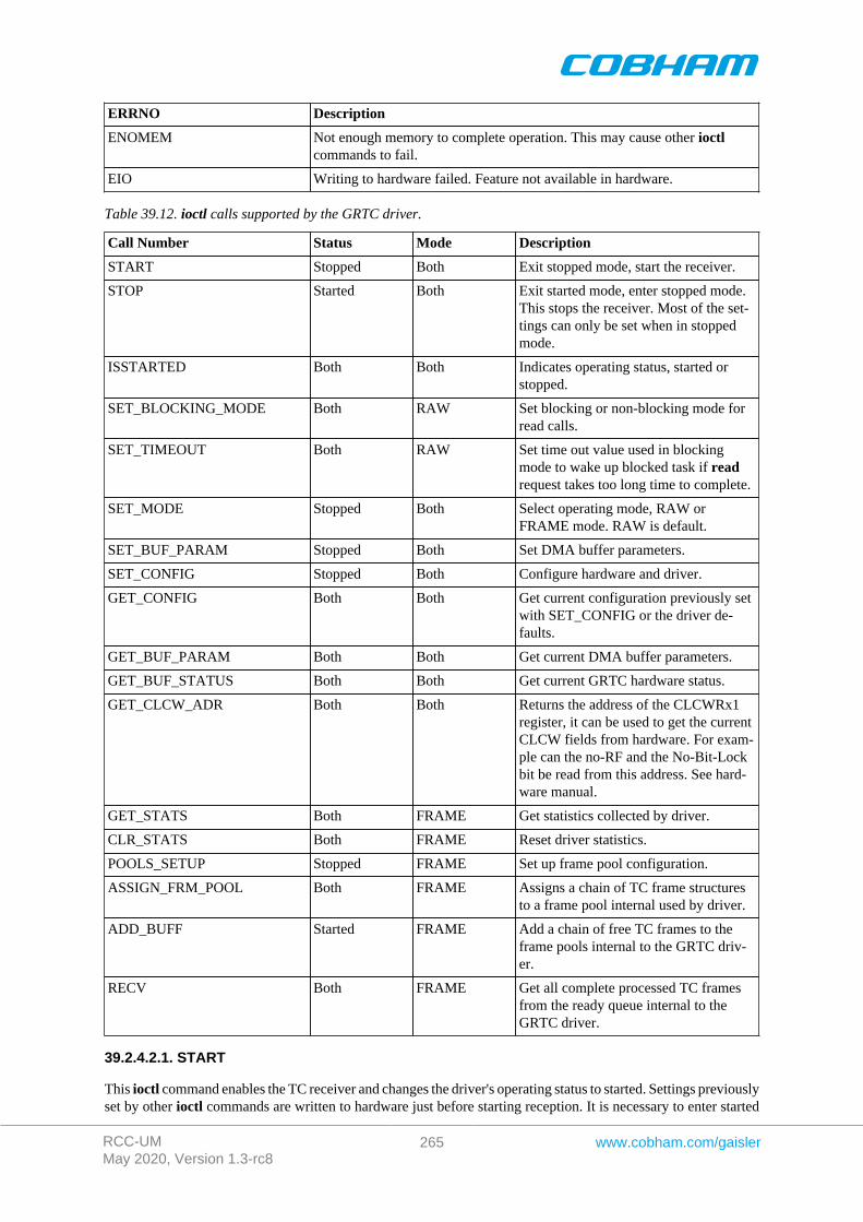
RCC-UMMay 2020, Version 1.3-rc8
265 www.cobham.com/gaisler
ERRNO Description
ENOMEM Not enough memory to complete operation. This may cause other ioctlcommands to fail.
EIO Writing to hardware failed. Feature not available in hardware.
Table 39.12. ioctl calls supported by the GRTC driver.
Call Number Status Mode Description
START Stopped Both Exit stopped mode, start the receiver.
STOP Started Both Exit started mode, enter stopped mode.This stops the receiver. Most of the set-tings can only be set when in stoppedmode.
ISSTARTED Both Both Indicates operating status, started orstopped.
SET_BLOCKING_MODE Both RAW Set blocking or non-blocking mode forread calls.
SET_TIMEOUT Both RAW Set time out value used in blockingmode to wake up blocked task if readrequest takes too long time to complete.
SET_MODE Stopped Both Select operating mode, RAW orFRAME mode. RAW is default.
SET_BUF_PARAM Stopped Both Set DMA buffer parameters.
SET_CONFIG Stopped Both Configure hardware and driver.
GET_CONFIG Both Both Get current configuration previously setwith SET_CONFIG or the driver de-faults.
GET_BUF_PARAM Both Both Get current DMA buffer parameters.
GET_BUF_STATUS Both Both Get current GRTC hardware status.
GET_CLCW_ADR Both Both Returns the address of the CLCWRx1register, it can be used to get the currentCLCW fields from hardware. For exam-ple can the no-RF and the No-Bit-Lockbit be read from this address. See hard-ware manual.
GET_STATS Both FRAME Get statistics collected by driver.
CLR_STATS Both FRAME Reset driver statistics.
POOLS_SETUP Stopped FRAME Set up frame pool configuration.
ASSIGN_FRM_POOL Both FRAME Assigns a chain of TC frame structuresto a frame pool internal used by driver.
ADD_BUFF Started FRAME Add a chain of free TC frames to theframe pools internal to the GRTC driv-er.
RECV Both FRAME Get all complete processed TC framesfrom the ready queue internal to theGRTC driver.
39.2.4.2.1. START
This ioctl command enables the TC receiver and changes the driver's operating status to started. Settings previouslyset by other ioctl commands are written to hardware just before starting reception. It is necessary to enter started
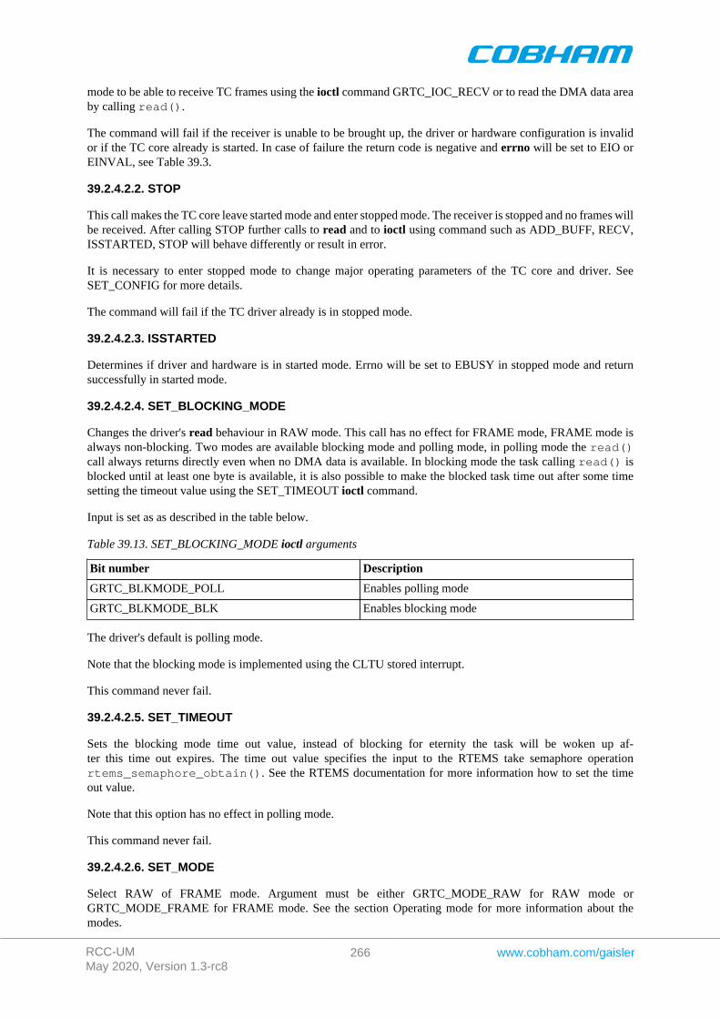
RCC-UMMay 2020, Version 1.3-rc8
266 www.cobham.com/gaisler
mode to be able to receive TC frames using the ioctl command GRTC_IOC_RECV or to read the DMA data areaby calling read().
The command will fail if the receiver is unable to be brought up, the driver or hardware configuration is invalidor if the TC core already is started. In case of failure the return code is negative and errno will be set to EIO orEINVAL, see Table 39.3.
39.2.4.2.2. STOP
This call makes the TC core leave started mode and enter stopped mode. The receiver is stopped and no frames willbe received. After calling STOP further calls to read and to ioctl using command such as ADD_BUFF, RECV,ISSTARTED, STOP will behave differently or result in error.
It is necessary to enter stopped mode to change major operating parameters of the TC core and driver. SeeSET_CONFIG for more details.
The command will fail if the TC driver already is in stopped mode.
39.2.4.2.3. ISSTARTED
Determines if driver and hardware is in started mode. Errno will be set to EBUSY in stopped mode and returnsuccessfully in started mode.
39.2.4.2.4. SET_BLOCKING_MODE
Changes the driver's read behaviour in RAW mode. This call has no effect for FRAME mode, FRAME mode isalways non-blocking. Two modes are available blocking mode and polling mode, in polling mode the read()call always returns directly even when no DMA data is available. In blocking mode the task calling read() isblocked until at least one byte is available, it is also possible to make the blocked task time out after some timesetting the timeout value using the SET_TIMEOUT ioctl command.
Input is set as as described in the table below.
Table 39.13. SET_BLOCKING_MODE ioctl arguments
Bit number Description
GRTC_BLKMODE_POLL Enables polling mode
GRTC_BLKMODE_BLK Enables blocking mode
The driver's default is polling mode.
Note that the blocking mode is implemented using the CLTU stored interrupt.
This command never fail.
39.2.4.2.5. SET_TIMEOUT
Sets the blocking mode time out value, instead of blocking for eternity the task will be woken up af-ter this time out expires. The time out value specifies the input to the RTEMS take semaphore operationrtems_semaphore_obtain(). See the RTEMS documentation for more information how to set the timeout value.
Note that this option has no effect in polling mode.
This command never fail.
39.2.4.2.6. SET_MODE
Select RAW of FRAME mode. Argument must be either GRTC_MODE_RAW for RAW mode orGRTC_MODE_FRAME for FRAME mode. See the section Operating mode for more information about themodes.
RCC-UMMay 2020, Version 1.3-rc8
267 www.cobham.com/gaisler
The driver defaults to RAW mode.
This calls fails if driver is in started mode or due to an illegal input argument.
39.2.4.2.7. SET_BUF_PARAM
This command is used to configure the DMA buffer area of the TC core. The argument is a pointer to an initializedgrtc_ioc_buf_params data structure described in the data structures section. The DMA buffer may be set to acustom location and length, or the driver may be requested to allocate a DMA buffer with the specified size. Ifthe custom location lsb is set to one the address is interpreted as a remote address as viewed from the GRTC core,not the CPU. This can be useful for GRTC cores found on another bus than the CPU, for example for a GRTXcore on a GR-RASTA-TMTC PCI board.
When GRTC is operated over SpaceWire an additional option is available, the dma_partition field, selectingfrom which memory partition the DMA area is allocated from. See AMBA Plug&Play SpaceWire bus driver foran description of memory allocation. The custom option described above is still available, however it identifiesthe cached memory area rather than the GRTC DMA area.
Trying to configure the DMA buffer area in started mode result in failure, and errno set to EBUSY. An invalidargument result in failure and errno set to EINVAL. The command will fail and errno set to ENOMEM whenthe driver is requested to allocate a buffer too large to be allocated by malloc().
39.2.4.2.8. SET_CONFIG
Configures the driver and core. This call updates the configuration that will be used by the driver during theSTART command and during operation. Enabling features not implemented by the TC core will result in EIOerror when starting the TC driver.
The input is a pointer to an initialized grtc_ioc_config structure described in Section 39.2.2.
This call fail if the TC core is in started mode, in that case errno will be set to EBUSY, or if a NULL pointer isgiven as argument, in that case errno will be set to EINVAL.
39.2.4.2.9. GET_CONFIG
Return the current configuration of the driver and hardware. The current configuration is either the driver andhardware defaults or the configuration previously set by the SET_CONFIG command.
The input to this ioctl command is a pointer to a data area of at least the size of a grtc_ioc_config structure.The data area will be stored according to the grtc_ioc_config data structure described in Section 39.2.2.
This command only fail if the pointer argument is invalid.
39.2.4.2.10. GET_BUF_PARAM
Get the current DMA buffer configuration. The argument is a pointer to an uninitialized grtc_ioc_buf_params datastructure described in the data structures section.
This command will fail if the input argument is invalid, errno will be set to EINVAL in such cases.
39.2.4.2.11. GET_HW_STATUS
Read current TC hardware state, the argument is a pointer to a data area where the hardware status will be stored.The status is stored using the layout of the grtc_ioc_hw_status described in the data structures section.
This command only fail if the pointer argument is invalid.
39.2.4.2.12. GET_CLCW_ADR
The address of the GRTC register "GRTC CLCW Register 1" is stored into a user provided location. The registeraddress may be used to access the current CLCW fields from the GRTC hardware. For example can the no-RFand the No-Bit-Lock bit be read from this address. See the hardware manual.

RCC-UMMay 2020, Version 1.3-rc8
268 www.cobham.com/gaisler
This command only fail if the pointer argument is invalid.
39.2.4.2.13. GET_STATS
This command copies the driver's internal statistics counters to a user provided data area. The format of the datawritten is described in the data structure subsection. See the grtc_ioc_stats data structure.
Note that the statistics only is available for the FRAME mode since it is only the FRAME mode that generatestatistics such as number of frames received and errors in header, in RAW mode the data is never processed justcopied to a user provided buffer.
The call will fail if the pointer to the data is invalid.
39.2.4.2.14. CLR_STATS
This command reset the driver's internal statistics counters.
This command never fail.
39.2.4.2.15. POOLS_SETUP
This command set up the frame pools internal to the driver. The frame pools must be configured before startingthe receiver in FRAME mode. For more information about frame pools see section Operating mode. The pools areconfigured by the input argument pointing to an initialized grtc_ioc_pools_setup data structure describedin the data structure subsection.
Note that the frame length must be sorted with the first frame pool having the shortest frame length.
The call will fail if the pointer to the data is invalid or if in RAW mode.
39.2.4.2.16. ASSIGN_FRM_POOL
Assigns a linked list of frames to a frame pool. The input argument is a pointer to agrtc_ioc_assign_frm_pool data structure containing the frame length identifying a pool and a linkedlist of frames that will be assign to the matching pool. All frames must be assigned to a frame pool beforeadded to the driver's frame pools using the command ADD_BUF. For more information about frame pools andassigning a frame to a frame pool see section Operating mode. See section data structures for a description ofgrtc_ioc_assign_frm_pool.
The frame pools, using POOLS_SETUP, must be set up before assigning frames to a frame pool.
This command fail and errno set to EINVAL is the input argument is invalid, the driver is in RAW mode or nomatching frame pool was found.
39.2.4.2.17. ADD_BUF
Adds a chain of frames to their respective frame pool for later use by the driver. The driver will use the addedframes when frames are received. The input argument is a pointer to a grtc_frame data structure, the first framein the chain, see the data section for a description of the grtc_frame structure.
Note, that the frame structure and any data pointed to by the frame added to the driver must not be accessed untilthe frame has been received using the ioctl command RECV.
The call will fail if the pointer to the data is invalid or if in RAW mode.
39.2.4.2.18. RECV
This command is used to process the DMA area and retrieve a linked list of successfully processed received frames.The input argument to RECV is a pointer to a grtc_list data structure, described in the data structure section.All currently processed frames will be put into data structure, head will point to the first and tail to the last framein the chain, cnt will hold the number of frames in the list.
RCC-UMMay 2020, Version 1.3-rc8
269 www.cobham.com/gaisler
39.2.5. Operating mode
In RAW mode the user can read out the raw data from the TC DMA buffer set up by the driver using the standardread() call. This enables the user to do custom processing of incoming frames. All TC DMA data is read onecontrol data byte for each frame data byte, for more information how to handle the data see the GRTC hardwaremanual. If the DMA buffer isn't read in time overflow may occur and data will be lost forcing the driver to stopthe receiver.
When the driver is operated in FRAME mode the driver is responsible to determine the start and end of each frame.It does so by looking at the TC frame length field and the GRTC control bytes provided for each frame data byte.The header and data is copied into a free frame taken from a frame pool internal to the driver, see next section forinformation about frame pools, an put at the end of a linked list with received frames that can be read by the userusing the ioctl command GRTC_IOC_RECV. After the user has processed the frame the frame is added againto the driver's frame pools using the ioctl command GRTC_IOC_ADD_BUFF. It is the users responsibility tomake sure that there always is frames available for the TC driver to copy frames into, otherwise the TC driverwill drop frames.
39.2.5.1. Driver frame pools
In FRAME mode a frame pool concept is used to group frames of equal frame length. Using multiple pools makeit possible for the driver to select a frame with a frame length as short as possible that still fit the incoming framedata and header. The driver is configured with multiple pools with different frame lengths, the more frame poolsthe smaller is the difference of the incoming frame length to the taken buffer the driver selects. The pools are setup using the ioctl command GRTC_IOC_POOLS_SETUP.
Every time a frame is added to one of the driver's pool, using the GRTC_IOC_ADD_BUFF command, the correctframe pool must be found to put it in. To simplify and make the frame pool detection faster each frame must beassigned to a frame pool once before use, assigning a frame with a pool must done by using the ioctl commandGRTC_IOC_ASSIGN_FRM_POOL.
39.2.6. Reception in FRAME mode
Receiving frames are done with the ioctl call using the command ADD_BUF and RECV. It is possible to receivemultiple frames in one call, the frames are provided to the driver using a linked list of frames. See the ioctlcommand RECV and ADD_BUF for more information.
39.2.7. Reception using RAW mode
Reception is done using the read call. An example is shown below:
unsigned char tc_rx_buf[512];
len = read(fd, tc_rx_buf, sizeof(tc_rx_buf));
The requested number of bytes to be read is given in the third argument. The messages will be stored in tc_rx_buf.The actual number of received bytes is returned by the function on success and -1 on failure. In the latter caseerrno is also set.
The data formatting is described in the hardware manual.
The call will fail if a null pointer is given, invalid buffer length, the TC core is in stopped mode, no data availablein non-blocking mode or due to a time out in blocking mode.
The blocking behaviour can be set using ioctl calls. In blocking mode the call will block until at least one byte hasbeen received, unless a time out has been given and that time has expired causes the driver to return ETIMEDOUT.In non-blocking mode, the call will return immediately and if no data was available -1 is returned and errno setappropriately. The table below shows the different errno values is returned.
Table 39.14. ERRNO values for read calls.
ERRNO Description
EINVAL A NULL pointer was passed as the data pointer or the length was illegal.
RCC-UMMay 2020, Version 1.3-rc8
270 www.cobham.com/gaisler
ERRNO Description
EBUSY TC core is in stopped mode. Switch to started mode by issuing a START ioctlcommand.
ETIMEDOUT In non-blocking mode no data were available in the DMA area, or in blockingmode and the time out has expired and still no data in DMA area.
ENODEV A blocking read was interrupted by the TC receiver has been stopped. Further callsto read will fail until the ioctl command START is issued again.
RCC-UMMay 2020, Version 1.3-rc8
271 www.cobham.com/gaisler
Chapter 40. GRTM GRLIB CCSDS Telemetry Driver
40.1. Introduction
This document is intended as an aid in getting started developing with Aeroflex Gaisler GRLIB GRTM Telemetry(TM) core using the driver described in this document. It describes accessing GRTM in a on- chip system andover PCI and SpaceWire. It briefly takes the reader through some of the most important steps in using the driversuch as starting TM communication, configuring the driver and sending TM frames. The reader is assumed to bewell acquainted with TM and RTEMS.
40.1.1. TM Hardware
See the GRTM core manual. When the GRTM core is accessed over SpaceWire RMAP is used.
40.1.2. Software Driver
The driver provides means for threads to send TM frames using standard I/O operations.
There are two drivers, one that supports GRTM on an on-chip AMBA bus and an AMBA bus accessed over PCI(on a GR-RASTA-TMTC board for example) and one driver that supports accessing the GRTM over SpaceWire.
40.1.2.1. GRTM over SpaceWire
There are some differences when the GRTM core is operated over SpaceWire, see below list for a summary.
• The GRTM driver manages one buffer per descriptor used to copy frame payload into. The payload is copiedover SpaceWire by the GRTM driver. The maximal frame length must be given in order for the driver toknow how much buffer space to allocate. It is controlled through the maxFrameLength driver resource.
• The driver has three new driver resources: maxFrameLength (maximal length of frames, used when al-locating buffer space), bdAllocPartition (partition used when allocating descriptor table, see AMBARMAP bus driver documentation) and frameAllocPartition (partition used when allocating bufferspace, see AMBA RMAP bus driver documentation).
• TM frames has an additional option COPY_DATA, it determines if the payload is to be copied to thedescriptor's buffer or if the address of the payload is an address that the GRTM core can read directly, forexample the payload may already reside on the SpaceWire node's memory ready to be transmitted. In thelatter case only the descriptor address pointer is written.
• The Frame options TRANSLATE and TRANSLATE_AND_REMEMBER has no effect.
40.2. User interface
The RTEMS GRTM driver supports the standard accesses to file descriptors such as open, close and ioctl. Userapplications include the grtm driver's header file which contains definitions of all necessary data structures andbit masks used when accessing the driver.
The driver enables the user to configure the hardware and to transmit TM frames. The allocation of TM framesis handled by the user and free frames are given to the driver that processes the frames for transmission in a twostep process. In the first step the driver schedules frames for transmission using the DMA descriptors or theyare put into an internal queue when all descriptors are in use, in the second step all sent frames are put into asecond queue that is emptied when the user reclaims the sent frames. The reclaimed frames can be reused in newtransmissions later on.
40.2.1. Driver registration
The registration of the driver is crucial for threads to be able to access the driver using standard means, such asopen. The function grtm_register whose prototype is provided in grtm.h is used for registering the driver. Itreturns 0 on success and 1 on failure. A typical register call from the LEON3 Init task:
if ( grtm_register(&amba_conf) ) printf(“GRTM register Failed\n”);
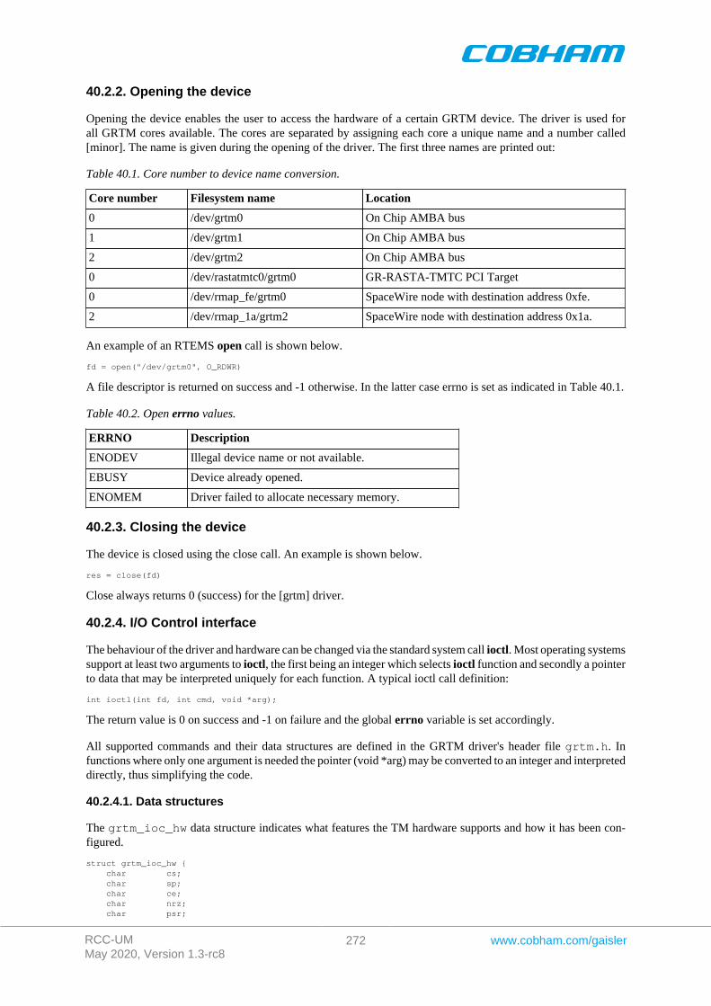
RCC-UMMay 2020, Version 1.3-rc8
272 www.cobham.com/gaisler
40.2.2. Opening the device
Opening the device enables the user to access the hardware of a certain GRTM device. The driver is used forall GRTM cores available. The cores are separated by assigning each core a unique name and a number called[minor]. The name is given during the opening of the driver. The first three names are printed out:
Table 40.1. Core number to device name conversion.
Core number Filesystem name Location
0 /dev/grtm0 On Chip AMBA bus
1 /dev/grtm1 On Chip AMBA bus
2 /dev/grtm2 On Chip AMBA bus
0 /dev/rastatmtc0/grtm0 GR-RASTA-TMTC PCI Target
0 /dev/rmap_fe/grtm0 SpaceWire node with destination address 0xfe.
2 /dev/rmap_1a/grtm2 SpaceWire node with destination address 0x1a.
An example of an RTEMS open call is shown below.
fd = open("/dev/grtm0", O_RDWR)
A file descriptor is returned on success and -1 otherwise. In the latter case errno is set as indicated in Table 40.1.
Table 40.2. Open errno values.
ERRNO Description
ENODEV Illegal device name or not available.
EBUSY Device already opened.
ENOMEM Driver failed to allocate necessary memory.
40.2.3. Closing the device
The device is closed using the close call. An example is shown below.
res = close(fd)
Close always returns 0 (success) for the [grtm] driver.
40.2.4. I/O Control interface
The behaviour of the driver and hardware can be changed via the standard system call ioctl. Most operating systemssupport at least two arguments to ioctl, the first being an integer which selects ioctl function and secondly a pointerto data that may be interpreted uniquely for each function. A typical ioctl call definition:
int ioctl(int fd, int cmd, void *arg);
The return value is 0 on success and -1 on failure and the global errno variable is set accordingly.
All supported commands and their data structures are defined in the GRTM driver's header file grtm.h. Infunctions where only one argument is needed the pointer (void *arg) may be converted to an integer and interpreteddirectly, thus simplifying the code.
40.2.4.1. Data structures
The grtm_ioc_hw data structure indicates what features the TM hardware supports and how it has been con-figured.
struct grtm_ioc_hw { char cs; char sp; char ce; char nrz; char psr;
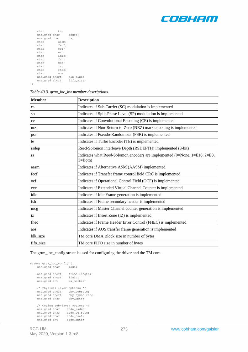
RCC-UMMay 2020, Version 1.3-rc8
273 www.cobham.com/gaisler
char te; unsigned char rsdep; unsigned char rs; char aasm; char fecf; char ocf; char evc; char idle; char fsh; char mcg; char iz; char fhec; char aos; unsigned short blk_size; unsigned short fifo_size;};
Table 40.3. grtm_ioc_hw member descriptions.
Member Description
cs Indicates if Sub Carrier (SC) modulation is implemented
sp Indicates if Split-Phase Level (SP) modulation is implemented
ce Indicates if Convolutional Encoding (CE) is implemented
nrz Indicates if Non-Return-to-Zero (NRZ) mark encoding is implemented
psr Indicates if Pseudo-Randomizer (PSR) is implemented
te Indicates if Turbo Encoder (TE) is implemented
rsdep Reed-Solomon interleave Depth (RSDEPTH) implemented (3-bit)
rs Indicates what Reed-Solomon encoders are implemented (0=None, 1=E16, 2=E8,3=Both)
aasm Indicates if Alternative ASM (AASM) implemented
fecf Indicates if Transfer frame control field CRC is implemented
ocf Indicates if Operational Control Field (OCF) is implemented
evc Indicates if Extended Virtual Channel Counter is implemented
idle Indicates if Idle Frame generation is implemented
fsh Indicates if Frame secondary header is implemented
mcg Indicates if Master Channel counter generation is implemented
iz Indicates if Insert Zone (IZ) is implemented
fhec Indicates if Frame Header Error Control (FHEC) is implemented
aos Indicates if AOS transfer frame generation is implemented
blk_size TM core DMA Block size in number of bytes
fifo_size TM core FIFO size in number of bytes
The grtm_ioc_config struct is used for configuring the driver and the TM core.
struct grtm_ioc_config { unsigned char mode;
unsigned short frame_length; unsigned short limit; unsigned int as_marker;
/* Physical layer options */ unsigned short phy_subrate; unsigned short phy_symbolrate; unsigned char phy_opts;
/* Coding sub-layer Options */ unsigned char code_rsdep; unsigned char code_ce_rate; unsigned char code_csel; unsigned int code_opts;
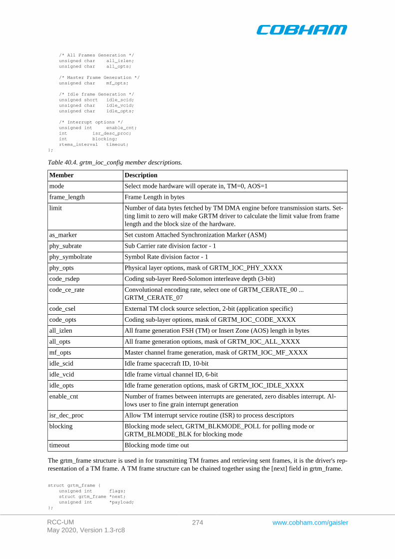
RCC-UMMay 2020, Version 1.3-rc8
274 www.cobham.com/gaisler
/* All Frames Generation */ unsigned char all_izlen; unsigned char all_opts;
/* Master Frame Generation */ unsigned char mf_opts;
/* Idle frame Generation */ unsigned short idle_scid; unsigned char idle_vcid; unsigned char idle_opts;
/* Interrupt options */ unsigned int enable_cnt; int isr_desc_proc; int blocking; rtems_interval timeout;};
Table 40.4. grtm_ioc_config member descriptions.
Member Description
mode Select mode hardware will operate in, TM=0, AOS=1
frame_length Frame Length in bytes
limit Number of data bytes fetched by TM DMA engine before transmission starts. Set-ting limit to zero will make GRTM driver to calculate the limit value from framelength and the block size of the hardware.
as_marker Set custom Attached Synchronization Marker (ASM)
phy_subrate Sub Carrier rate division factor - 1
phy_symbolrate Symbol Rate division factor - 1
phy_opts Physical layer options, mask of GRTM_IOC_PHY_XXXX
code_rsdep Coding sub-layer Reed-Solomon interleave depth (3-bit)
code_ce_rate Convolutional encoding rate, select one of GRTM_CERATE_00 ...GRTM_CERATE_07
code_csel External TM clock source selection, 2-bit (application specific)
code_opts Coding sub-layer options, mask of GRTM_IOC_CODE_XXXX
all_izlen All frame generation FSH (TM) or Insert Zone (AOS) length in bytes
all_opts All frame generation options, mask of GRTM_IOC_ALL_XXXX
mf_opts Master channel frame generation, mask of GRTM_IOC_MF_XXXX
idle_scid Idle frame spacecraft ID, 10-bit
idle_vcid Idle frame virtual channel ID, 6-bit
idle_opts Idle frame generation options, mask of GRTM_IOC_IDLE_XXXX
enable_cnt Number of frames between interrupts are generated, zero disables interrupt. Al-lows user to fine grain interrupt generation
isr_dec_proc Allow TM interrupt service routine (ISR) to process descriptors
blocking Blocking mode select, GRTM_BLKMODE_POLL for polling mode orGRTM_BLMODE_BLK for blocking mode
timeout Blocking mode time out
The grtm_frame structure is used in for transmitting TM frames and retrieving sent frames, it is the driver's rep-resentation of a TM frame. A TM frame structure can be chained together using the [next] field in grtm_frame.
struct grtm_frame { unsigned int flags; struct grtm_frame *next; unsigned int *payload;};

RCC-UMMay 2020, Version 1.3-rc8
275 www.cobham.com/gaisler
Table 40.5. grtm_frame member descriptions.
Member Description
flags Mask indicating options, transmission state and errors for the frame.GRTM_FLAGS_XXX. See Table 40.5
next Points to next TM frame. This field is used to make driver process multiple TMFrames at the same time, avoiding multiple ioctl calls.
payload Points to a data area holding the complete TM frame. The area include fields suchas header, payload, OCF, CRC.
Table 40.6. Frame flags descriptions.
Flag Description
GRTM_FLAGS_SENT Indicates whether the frame has been transmitted or not
GRTM_FLAGS_ERR Indicates if errors has been experienced during transmission of theframe
GRTM_FLAGS_TS Generate Time Strobe (TS) for the frame
GRTM_FLAGS_MCB Bypass the TM core's Master Channel Counter generation
GRTM_FLAGS_FSHB Bypass the TM core's Frame Secondary Header (FSH) generation
GRTM_FLAGS_OCFB Bypass the TM core's Operational Control Field (OCF) generation
GRTM_FLAGS_FHECB Bypass the TM core's Frame Header Error Control (FHEC) generation
GRTM_FLAGS_IZB Bypass the TM core's Insert Zone (IZ) generation
GRTM_FLAGS_FECFB Bypass the TM core's Frame Error Control Field (FECF) generation
COPY_DATA This option has effect only on the SpaceWire version of the driver. In-dicates if the TM frame payload should be copied into the assigneddescriptor's buffer or not. If this option is not set then the payload ad-dress is assumed to be readable by the GRTM core and the descriptoraddress pointer is written with the address of the payload directly.
TRANSLATE Translate frame payload address from CPU address to remote bus (thebus GRTM is resident on). This is useful when dealing with buffers onremote buses, for example when GRTM is on a AMBA bus accessedover PCI. This is the case for GR-RASTA-TMTC.
TRANSLATE_AND_REMEMBER As TRANSLATE, however if the translated payload address equals thepayload address the TRANSLATE_AND_REMEMBER bit is clearedand the TRANSLATE bit is set. Not used in SpaceWire version of driv-er.
The grtm_list structure represents a linked list, a chain of TM frames. The data structure holds the first frame andlast frame in chain.
struct grtm_list { struct grtm_frame *head; struct grtm_frame *tail;};
Table 40.7. grtm_list member descriptions.
Member Description
head First TM frame in chain
tail Last TM frame in chain, last frame in list must have it's next field set toNULL
The grtm_ioc_stats structure contain statistics collected by the driver.
struct grtm_ioc_stats {
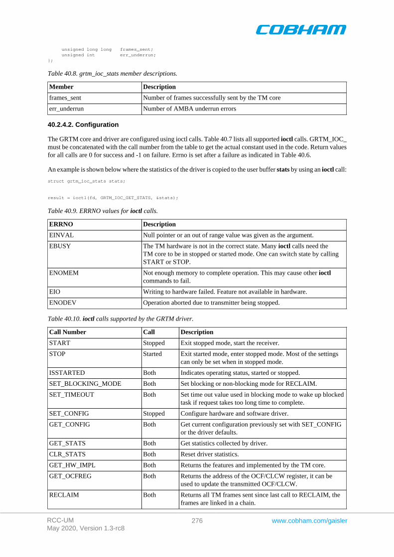
RCC-UMMay 2020, Version 1.3-rc8
276 www.cobham.com/gaisler
unsigned long long frames_sent; unsigned int err_underrun;};
Table 40.8. grtm_ioc_stats member descriptions.
Member Description
frames_sent Number of frames successfully sent by the TM core
err_underrun Number of AMBA underrun errors
40.2.4.2. Configuration
The GRTM core and driver are configured using ioctl calls. Table 40.7 lists all supported ioctl calls. GRTM_IOC_must be concatenated with the call number from the table to get the actual constant used in the code. Return valuesfor all calls are 0 for success and -1 on failure. Errno is set after a failure as indicated in Table 40.6.
An example is shown below where the statistics of the driver is copied to the user buffer stats by using an ioctl call:
struct grtm_ioc_stats stats;
result = ioctl(fd, GRTM_IOC_GET_STATS, &stats);
Table 40.9. ERRNO values for ioctl calls.
ERRNO Description
EINVAL Null pointer or an out of range value was given as the argument.
EBUSY The TM hardware is not in the correct state. Many ioctl calls need theTM core to be in stopped or started mode. One can switch state by callingSTART or STOP.
ENOMEM Not enough memory to complete operation. This may cause other ioctlcommands to fail.
EIO Writing to hardware failed. Feature not available in hardware.
ENODEV Operation aborted due to transmitter being stopped.
Table 40.10. ioctl calls supported by the GRTM driver.
Call Number Call Description
START Stopped Exit stopped mode, start the receiver.
STOP Started Exit started mode, enter stopped mode. Most of the settingscan only be set when in stopped mode.
ISSTARTED Both Indicates operating status, started or stopped.
SET_BLOCKING_MODE Both Set blocking or non-blocking mode for RECLAIM.
SET_TIMEOUT Both Set time out value used in blocking mode to wake up blockedtask if request takes too long time to complete.
SET_CONFIG Stopped Configure hardware and software driver.
GET_CONFIG Both Get current configuration previously set with SET_CONFIGor the driver defaults.
GET_STATS Both Get statistics collected by driver.
CLR_STATS Both Reset driver statistics.
GET_HW_IMPL Both Returns the features and implemented by the TM core.
GET_OCFREG Both Returns the address of the OCF/CLCW register, it can beused to update the transmitted OCF/CLCW.
RECLAIM Both Returns all TM frames sent since last call to RECLAIM, theframes are linked in a chain.

RCC-UMMay 2020, Version 1.3-rc8
277 www.cobham.com/gaisler
Call Number Call Description
SEND Started Add a chain of TM frames to the transmission queue of theGRTM driver.
40.2.4.2.1. START
This ioctl command enables the TM transmitter and changes the driver's operating status to started. Settings pre-viously set by other ioctl commands are written to hardware just before starting transmission. It is necessary toenter started mode to be able to send TM frames using the ioctl command GRTM_IOC_SEND.
The command will fail if the transmitter is unable to be brought up, the driver or hardware configuration is invalidor if the TM core already is started. In case of failure the return code is negative and errno will be set to EIO orEINVAL, see Table 40.6.
40.2.4.2.2. STOP
This call makes the TM core leave started mode and enter stopped mode. The transmitter is stopped and no frameswill be sent. After calling STOP further ioctl commands such as SEND, RECLAIM, ISSTARTED, STOP willbehave differently or result in error.
It is necessary to enter stopped mode to change major operating parameters of the TM core and driver. SeeSET_CONFIG for more details.
The command will fail if the TM driver already is in stopped mode.
40.2.4.2.3. ISSTARTED
Determines if driver and hardware is in started mode. Errno will be set to EBUSY in stopped mode and returnsuccessfully in started mode.
40.2.4.2.4. SET_BLOCKING_MODE
Changes the driver's GRTM_IOC_RECLAIM command behaviour. Two modes are available blocking mode andpolling mode, in polling mode the ioctl command RECLAIM always return directly even when no frames areavailable. In blocking mode the task calling RECLAIM is blocked until at least one frame can be reclaimed, it isalso possible to make the blocked task time out after some time setting the timeout value using the SET_CONFIGor SET_TIMEOUT ioctl commands.
The argument is set as as described in the table below.
Table 40.11. SET_BLOCKING_MODE ioctl arguments
Bit Number Description
GRTM_BLKMODE_POLL Enables polling mode
GRTM_BLKMODE_BLK Enables blocking mode
The driver's default is polling mode.
Note that the blocking mode is implemented using the DMA transmit frame interrupt, changing theisr_desc_proc parameter of the SET_CONFIG command effects the blocking mode characteristics. For ex-ample, enabling interrupt generation every tenth TM frame will cause the blocked task to be woken up after max-imum ten frames when going into blocked mode.
This command never fail.
40.2.4.2.5. SET_TIMEOUT
Sets the blocking mode time out value, instead of blocking for eternity the task will be woken up af-ter this time out expires. The time out value specifies the input to the RTEMS take semaphore operation

RCC-UMMay 2020, Version 1.3-rc8
278 www.cobham.com/gaisler
rtems_semaphore_obtain(). See the RTEMS documentation for more information how to set the timeout value.
Note that this option has no effect in polling mode.
Note that this option is also set by SET_CONFIG.
40.2.4.2.6. SET_CONFIG
Configures the driver and core. This call updates the configuration that will be used by the driver during the STARTcommand and during operation. Enabling features not implemented by the TM core will result in EIO error whenstarting the TM driver. The hardware features available can be obtained by the GET_HW_IMPL command.
The input is a pointer to an initialized grtm_ioc_config structure described in section Section 40.2.4.1.
Note that the time out value and blocking mode can also be set with SET_TIMEOUT andSET_BLOCKING_MODE.
This call fail if the TM core is in started mode, in that case errno will be set to EBUSY, or if a NULL pointer isgiven as argument, in that case errno will be set to EINVAL.
40.2.4.2.7. GET_CONFIG
Returns the current configuration of the driver and hardware. The current configuration is either the driver andhardware defaults or the configuration previously set by the SET_CONFIG command.
The input to this ioctl command is a pointer to a data area of at least the size of a grtm_ioc_config structure.The data area will be updated according to the grtm_ioc_config data structure described in Section 40.2.4.1.
This command only fail if the pointer argument is invalid.
40.2.4.2.8. GET_STATS
This command copies the driver's internal statistics counters to a user provided data area. The format of the datawritten is described in the data structure subsection. See the grtm_ioc_stats data structure.
The call will fail if the pointer to the data is invalid.
40.2.4.2.9. CLR_STATS
This command reset the driver's internal statistics counters.
This command never fail.
40.2.4.2.10. GET_HW_IMPL
This command copies the TM core's features implemented to a user provided data area. The format of the datawritten is described in the data structure subsection. See the grtm_ioc_hw data structure.
Knowing the features supported by hardware can be used to make software run on multiple implementations ofthe TM core.
40.2.4.2.11. GET_OCFREG
The address of the GRTM register "GRTM Operational Control Field Register" is stored into a user providedlocation. The register address may be used to updated the CLCW or OCF value transmitted in TM frames toground without using an ioctl command to perform the request. This address is typically used by Telecommand(TC) software to tell ground of the current FARM/COP state.
Note that OCF/ CLCW is transmitted only in started mode.
This command never fail.
RCC-UMMay 2020, Version 1.3-rc8
279 www.cobham.com/gaisler
40.2.4.2.12. RECLAIM
Returns processed TM frames to user. All frames returned has been provided by the user in previous calls to SEND,and need not all to have been successfully sent. RECLAIM can be configured to operate in polling mode, blockingmode and blocking mode with a time out. In polling mode the task always returns with or without processedframes, in blocking mode the task is blocked until at least one frame has been processed. See the ioctl commandSET_CONFIG and SET_BLOCKING_MODE to change mode of the RECLAIM command.
RECLAIM stores a linked list of processed TM frames into the data area pointed to by the user argument. Theformat for the stored data follows the layout of the grtm_list structure described in Section 40.2.2. Thegrtm_list structure holds the first and last TM frame processed by the driver. The flags field indicates if theframe was sent or if errors were experienced during transmission of this frame. See Table 40.6 for flags details.
In started mode, this command enables scheduled TM frames for transmission as descriptors become free duringthe processing of received TM frames.
The call will fail if the pointer to the data area is invalid (EINVAL), the RECLAIM call operates in blockingmode and the time out expires (ETIMEDOUT) or the driver was stopped during the calling task was blocked(ENODEV). See table below.
Table 40.12. ERRNO values for RECLAIM
ERRNO Description
EINVAL An invalid argument.
ETIMEDOUT The blocked task was timed out and still no frames was transmitted.
ENODEV The calling task was woken up from blocking mode by the transmitter being stopped. TheTM driver has has entered stopped mode. Further calls to RECLAIM will retrieve sent andunsent frames.
40.2.4.2.13. SEND
Scheduling ready TM frames for transmission is done with the ioctl command SEND. The input is a linked list ofTM frames to be scheduled. When all TM DMA descriptors are active, enabled and linked to a frame to transmit,the remaining frames are queued internally by the driver. The TM core is capable of generating parts of the header,the CRC and OCF/CLCW depending on the implementation and configuration of the TM core. The implementedfeatures are selected by setting generics in the VHDL model, the implemented features can be read using theGET_HW_IMPL command. The features enabled is controlled by the SET_CONFIG command. For featuresavailable see the hardware manual for the TM core. The hardware generated parts may be overridden by settingthe flags of the input TM frame structure accordingly.
Every call to SEND will trigger scheduled TM frames for transmission, calling SEND with the argument set toNULL will thus trigger previously scheduled TM frames for transmission. This might be necessary when interruptsare not used to process descriptors or when interrupt generation for TM frames are disabled, see Section 40.2.4.2.7.
The input to SEND is a pointer to a grtm_list data structure described in Section 40.2.4.1. The head and tailfields of the data structure points to the first and the last TM frame to be scheduled for transmission. The TM framestructure, grtm_frame, used is described in Section 40.2.2. The data area length pointed to by the payload fieldis assumed to be at least frame length long. The frame length is set by the SET_CONFIG command. The hardwaregenerated parts may be overridden by setting the flags field of the TM frame structure accordingly.
Note, that the frame structure and any data pointed to by the frame scheduled for transmission must not be accesseduntil the frame has been reclaimed using the ioctl command RECLAIM.
SEND will fail if the input frame list is incorrectly set up, errno will be set to EINVAL in such cases.
40.2.5. Transmission
Transmitting frames are done with the ioctl call using the command SEND and RECLAIM. It is possible to sendmultiple frames in one call, the frames are provided to the driver using a linked list of frames. See the ioctlcommands SEND and RECLAIM for more information.
RCC-UMMay 2020, Version 1.3-rc8
280 www.cobham.com/gaisler
Chapter 41. GRCTM driver
41.1. Introduction
This section describes the GRLIB GRCTM (CCSDS Time Manager) device driver interface. The driver imple-ments a simple interface to read and write registers of the core and interrupt handling. The driver supports theon-chip AMBA and the AMBA-over-PCI bus. It relies on the driver manager for device discovery and interrupthandling.
The GRCTM driver require the Driver Manager.
In order to use the driver interface the user must be well acquainted with GRCTM hardware, see hardware manual.
41.1.1. Examples
There is an example available that illustrates how the GRCTM driver interface can be used to configure theGRCTM core. The example application can be configured as a Time-Master or Time- Slave demonstrating bothsending and receiving time over TimeWire and how it can be connected to the SPWCUC for time-codes and send-ing time-packets according to CCSDS Unsegmented Code Transfer Protocol using the RTEMS GRSPW driver.
Note that the example may need to be configured, see the TIME_SYNC_* options.
The example can be built by running:
$ cd /opt/rtems-4.10/src/samples/1553$ make rtems-gr1553bcbm
41.1.2. User interface
41.1.2.1. Overview
The GRCTM software driver provides access to the GRCTM core's registers and helps with device detection,driver loading and interrupt handling.
The driver sources and interface definitions are listed in the table below, the path is given relative to the SPARCBSP sources c/src/lib/libbsp/sparc.
Table 41.1. GRCTM driver Source location
Filename Description
shared/time/grctm.c GRCTM Driver source
shared/include/grctm.h GRCTM Driver interface declaration
41.1.2.1.1. Accessing the GRCTM core
A GRCTM core is accessed by first opening a specific GRCTM device by callinggrctm_open(INSTANCE_NUMBER), after successfully opening a device the returned value of grctm_opencan be used as input other functions in the GRCTM driver interface. Registers can be accessed and interruptsenabled.
41.1.2.1.2. Interrupt service
The GRCTM core can be programmed to interrupt the CPU on certain events, see hardware manual. All interruptscauses the driver's interrupt service routine (ISR) to be called, it gathers statistics and call the optional user assignedcallback. The callback is registered using the function grctm_int_register().
41.1.2.2. Application Programming Interface
The GRCTM driver API consists of the functions in the table below.
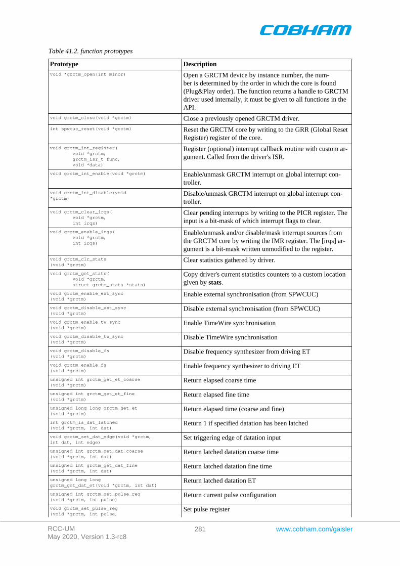
RCC-UMMay 2020, Version 1.3-rc8
281 www.cobham.com/gaisler
Table 41.2. function prototypes
Prototype Descriptionvoid *grctm_open(int minor) Open a GRCTM device by instance number, the num-
ber is determined by the order in which the core is found(Plug&Play order). The function returns a handle to GRCTMdriver used internally, it must be given to all functions in theAPI.
void grctm_close(void *grctm) Close a previously opened GRCTM driver.
int spwcuc_reset(void *grctm) Reset the GRCTM core by writing to the GRR (Global ResetRegister) register of the core.
void grctm_int_register( void *grctm, grctm_isr_t func, void *data)
Register (optional) interrupt callback routine with custom ar-gument. Called from the driver's ISR.
void grctm_int_enable(void *grctm) Enable/unmask GRCTM interrupt on global interrupt con-troller.
void grctm_int_disable(void *grctm)
Disable/unmask GRCTM interrupt on global interrupt con-troller.
void grctm_clear_irqs( void *grctm, int irqs)
Clear pending interrupts by writing to the PICR register. Theinput is a bit-mask of which interrupt flags to clear.
void grctm_enable_irqs( void *grctm, int irqs)
Enable/unmask and/or disable/mask interrupt sources fromthe GRCTM core by writing the IMR register. The [irqs] ar-gument is a bit-mask written unmodified to the register.
void grctm_clr_stats(void *grctm)
Clear statistics gathered by driver.
void grctm_get_stats( void *grctm, struct grctm_stats *stats)
Copy driver's current statistics counters to a custom locationgiven by stats.
void grctm_enable_ext_sync(void *grctm)
Enable external synchronisation (from SPWCUC)
void grctm_disable_ext_sync(void *grctm)
Disable external synchronisation (from SPWCUC)
void grctm_enable_tw_sync(void *grctm)
Enable TimeWire synchronisation
void grctm_disable_tw_sync(void *grctm)
Disable TimeWire synchronisation
void grctm_disable_fs(void *grctm)
Disable frequency synthesizer from driving ET
void grctm_enable_fs(void *grctm)
Enable frequency synthesizer to driving ET
unsigned int grctm_get_et_coarse(void *grctm)
Return elapsed coarse time
unsigned int grctm_get_et_fine(void *grctm)
Return elapsed fine time
unsigned long long grctm_get_et(void *grctm)
Return elapsed time (coarse and fine)
int grctm_is_dat_latched(void *grctm, int dat)
Return 1 if specified datation has been latched
void grctm_set_dat_edge(void *grctm, int dat, int edge)
Set triggering edge of datation input
unsigned int grctm_get_dat_coarse(void *grctm, int dat)
Return latched datation coarse time
unsigned int grctm_get_dat_fine(void *grctm, int dat)
Return latched datation fine time
unsigned long long grctm_get_dat_et(void *grctm, int dat)
Return latched datation ET
unsigned int grctm_get_pulse_reg(void *grctm, int pulse)
Return current pulse configuration
void grctm_set_pulse_reg(void *grctm, int pulse,
Set pulse register
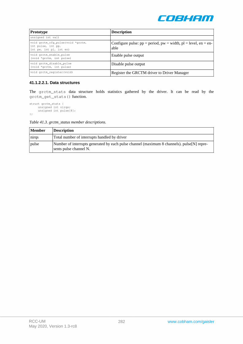
RCC-UMMay 2020, Version 1.3-rc8
282 www.cobham.com/gaisler
Prototype Descriptionunsigned int val)
void grctm_cfg_pulse(void *grctm, int pulse, int pp, int pw, int pl, int en)
Configure pulse: pp = period, pw = width, pl = level, en = en-able
void grctm_enable_pulse(void *grctm, int pulse)
Enable pulse output
void grctm_disable_pulse(void *grctm, int pulse)
Disable pulse output
void grctm_register(void) Register the GRCTM driver to Driver Manager
41.1.2.2.1. Data structures
The grctm_stats data structure holds statistics gathered by the driver. It can be read by thegrctm_get_stats() function.
struct grctm_stats { unsigned int nirqs; unsigned int pulse[8];};
Table 41.3. grctm_status member descriptions.
Member Description
nirqs Total number of interrupts handled by driver
pulse Number of interrupts generated by each pulse channel (maximum 8 channels). pulse[N] repre-sents pulse channel N.
RCC-UMMay 2020, Version 1.3-rc8
283 www.cobham.com/gaisler
Chapter 42. SPWCUC driver
42.1. Introduction
This section describes the GRLIB SPWCUC (SpaceWire – CCSDS Unsegmented Code Transfer Protocol) devicedriver interface. The driver implements a simple interface to read and write registers of the core, interrupt handling.The driver supports the on-chip AMBA and the AMBA-over-PCI bus. It relies on the driver manager for devicediscovery and interrupt handling.
The SPWCUC driver require the Driver Manager.
In order to use the driver interface the user must be well acquainted with SPWCUC hardware, see hardware manual.
42.1.1. Examples
There is an example available that illustrates how the SPWCUC driver interface can be used to configure theSPWCUC core and manage interrupts. The example application can be configured as a Time-Master or Time-Slave demonstrating both sending and receiving SpaceWire time-codes and sending time-packets according toCCSDS Unsegmented Code Transfer Protocol using the RTEMS GRSPW driver.
Note that the example may need to be configured, see the TIME_SYNC_* options.
The example can be built by running:
$ cd /opt/rtems-4.10/src/samples/1553$ make rtems-gr1553bcbm
42.2. User interface
42.2.1. Overview
The SPWCUC software driver provides access to the SPWCUC core's registers and helps with device detection,driver loading and interrupt handling.
The driver sources and interface definitions are listed in the table below, the path is given relative to the SPARCBSP sources c/src/lib/libbsp/sparc.
Table 42.1. SPWCUC driver Source location
Filename Description
shared/time/spwcuc.c SPWCUC Driver source
shared/include/spwcuc.h SPWCUC Driver interface declaration
42.2.1.1. Accessing the SPWCUC core
A SPWCUC core is accessed by first opening a specific SPWCUC device by callingspwcuc_open(INSTANCE_NUMBER), after successfully opening a device the returned value ofspwcuc_open can be used as input other functions in the SPWCUC driver interface. Registers can be accessedand interrupts can be enabled.
42.2.1.2. Interrupt service
The SPWCUC core can be programmed to interrupt the CPU on certain events, see hardware manual. All interruptscauses the driver's interrupt service routine (ISR) to be called, it gathers statistics and call the optional user assignedcallback. The callback is registered using the function spwcuc_int_register().
42.2.2. Application Programming Interface
The SPWCUC driver API consists of the functions in the table below.
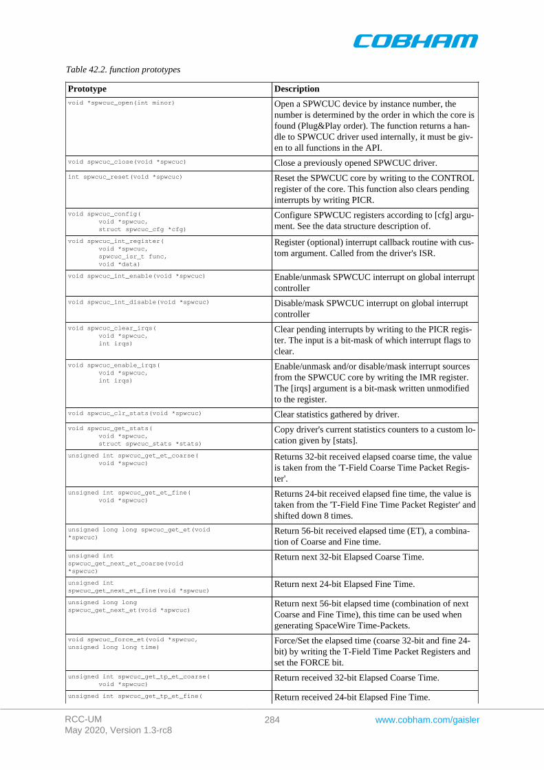
RCC-UMMay 2020, Version 1.3-rc8
284 www.cobham.com/gaisler
Table 42.2. function prototypes
Prototype Descriptionvoid *spwcuc_open(int minor) Open a SPWCUC device by instance number, the
number is determined by the order in which the core isfound (Plug&Play order). The function returns a han-dle to SPWCUC driver used internally, it must be giv-en to all functions in the API.
void spwcuc_close(void *spwcuc) Close a previously opened SPWCUC driver.
int spwcuc_reset(void *spwcuc) Reset the SPWCUC core by writing to the CONTROLregister of the core. This function also clears pendinginterrupts by writing PICR.
void spwcuc_config( void *spwcuc, struct spwcuc_cfg *cfg)
Configure SPWCUC registers according to [cfg] argu-ment. See the data structure description of.
void spwcuc_int_register( void *spwcuc, spwcuc_isr_t func, void *data)
Register (optional) interrupt callback routine with cus-tom argument. Called from the driver's ISR.
void spwcuc_int_enable(void *spwcuc) Enable/unmask SPWCUC interrupt on global interruptcontroller
void spwcuc_int_disable(void *spwcuc) Disable/mask SPWCUC interrupt on global interruptcontroller
void spwcuc_clear_irqs( void *spwcuc, int irqs)
Clear pending interrupts by writing to the PICR regis-ter. The input is a bit-mask of which interrupt flags toclear.
void spwcuc_enable_irqs( void *spwcuc, int irqs)
Enable/unmask and/or disable/mask interrupt sourcesfrom the SPWCUC core by writing the IMR register.The [irqs] argument is a bit-mask written unmodifiedto the register.
void spwcuc_clr_stats(void *spwcuc) Clear statistics gathered by driver.
void spwcuc_get_stats( void *spwcuc, struct spwcuc_stats *stats)
Copy driver's current statistics counters to a custom lo-cation given by [stats].
unsigned int spwcuc_get_et_coarse( void *spwcuc)
Returns 32-bit received elapsed coarse time, the valueis taken from the 'T-Field Coarse Time Packet Regis-ter'.
unsigned int spwcuc_get_et_fine( void *spwcuc)
Returns 24-bit received elapsed fine time, the value istaken from the 'T-Field Fine Time Packet Register' andshifted down 8 times.
unsigned long long spwcuc_get_et(void *spwcuc)
Return 56-bit received elapsed time (ET), a combina-tion of Coarse and Fine time.
unsigned int spwcuc_get_next_et_coarse(void *spwcuc)
Return next 32-bit Elapsed Coarse Time.
unsigned int spwcuc_get_next_et_fine(void *spwcuc)
Return next 24-bit Elapsed Fine Time.
unsigned long long spwcuc_get_next_et(void *spwcuc)
Return next 56-bit elapsed time (combination of nextCoarse and Fine Time), this time can be used whengenerating SpaceWire Time-Packets.
void spwcuc_force_et(void *spwcuc, unsigned long long time)
Force/Set the elapsed time (coarse 32-bit and fine 24-bit) by writing the T-Field Time Packet Registers andset the FORCE bit.
unsigned int spwcuc_get_tp_et_coarse( void *spwcuc)
Return received 32-bit Elapsed Coarse Time.
unsigned int spwcuc_get_tp_et_fine( Return received 24-bit Elapsed Fine Time.
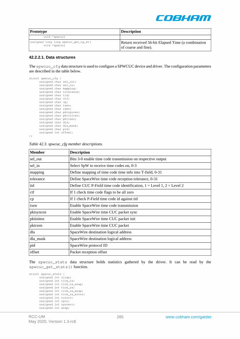
RCC-UMMay 2020, Version 1.3-rc8
285 www.cobham.com/gaisler
Prototype Description void *spwcuc)
unsigned long long spwcuc_get_tp_et( void *spwcuc)
Return received 56-bit Elapsed Time (a combinationof coarse and fine).
42.2.2.1. Data structures
The spwcuc_cfg data structure is used to configure a SPWCUC device and driver. The configuration parametersare described in the table below.
struct spwcuc_cfg { unsigned char sel_out; unsigned char sel_in; unsigned char mapping; unsigned char tolerance; unsigned char tid; unsigned char ctf; unsigned char cp; unsigned char txen; unsigned char rxen; unsigned char pktsyncen; unsigned char pktiniten; unsigned char pktrxen; unsigned char dla; unsigned char dla_mask; unsigned char pid; unsigned int offset;};
Table 42.3. spwcuc_cfg member descriptions.
Member Description
sel_out Bits 3-0 enable time code transmission on respective output
sel_in Select SpW to receive time codes on, 0-3
mapping Define mapping of time code time info into T-field, 0-31
tolerance Define SpaceWire time code reception tolerance, 0-31
tid Define CUC P-Field time code identification, 1 = Level 1, 2 = Level 2
ctf If 1 check time code flags to be all zero
cp If 1 check P-Field time code id against tid
txen Enable SpaceWire time code transmission
pktsyncen Enable SpaceWire time CUC packet sync
pktiniten Enable SpaceWire time CUC packet init
pktrxen Enable SpaceWire time CUC packet
dla SpaceWire destination logical address
dla_mask SpaceWire destination logical address
pid SpaceWire protocol ID
offset Packet reception offset
The spwcuc_stats data structure holds statistics gathered by the driver. It can be read by thespwcuc_get_stats() function.
struct spwcuc_stats { unsigned int nirqs; unsigned int tick_tx; unsigned int tick_tx_wrap; unsigned int tick_rx; unsigned int tick_rx_wrap; unsigned int tick_rx_error; unsigned int tolerr; unsigned int sync; unsigned int syncerr; unsigned int wrap;
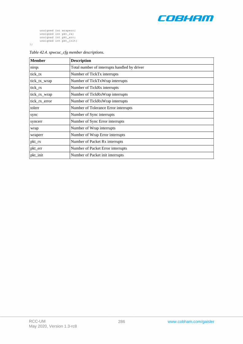
RCC-UMMay 2020, Version 1.3-rc8
286 www.cobham.com/gaisler
unsigned int wraperr; unsigned int pkt_rx; unsigned int pkt_err; unsigned int pkt_init;};
Table 42.4. spwcuc_cfg member descriptions.
Member Description
nirqs Total number of interrupts handled by driver
tick_tx Number of TickTx interrupts
tick_tx_wrap Number of TickTxWrap interrupts
tick_rx Number of TickRx interrupts
tick_rx_wrap Number of TickRxWrap interrupts
tick_rx_error Number of TickRxWrap interrupts
tolerr Number of Tolerance Error interrupts
sync Number of Sync interrupts
syncerr Number of Sync Error interrupts
wrap Number of Wrap interrupts
wraperr Number of Wrap Error interrupts
pkt_rx Number of Packet Rx interrupts
pkt_err Number of Packet Error interrupts
pkt_init Number of Packet init interrupts
RCC-UMMay 2020, Version 1.3-rc8
287 www.cobham.com/gaisler
Chapter 43. GRPWRX GRLIB PacketWire Receiver driver
43.1. Introduction
This document is intended as an aid in getting started developing with Aeroflex Gaisler GRLIB PACKETWIRERX (GRPWRX) core using the driver described in this document. It describes accessing GRPWRX in a on-chipsystem and over PCI. It briefly takes the reader through some of the most important steps in using the driversuch as starting GRPWRX communication, configuring the driver and receiving GRPWRX packets. The readeris assumed to be well acquainted with GRPWRX and RTEMS.
43.1.1. Software Driver
The driver provides means for threads to receive GRPWRX packets using standard I/O operations.
43.2. User interface
The RTEMS grpwrx driver supports the standard accesses to file descriptors such as open, close and ioctl. Userapplications include the grpwrx driver's header file which contains definitions of all necessary data structures andbit masks used when accessing the driver.
The driver enables the user to configure the hardware and to receive GRPWRX packets. The allocation of GRP-WRX packets is handled by the user and free packets are given to the driver that processes the packets for receptionin a two step process. In the first step the driver schedules packets for reception using the DMA descriptors orthey are put into an internal queue when all descriptors are in use, in the second step all received packets are putinto a second queue that is emptied when the user reclaims the received packets. The reclaimed packets can thenbe reused in new reception later on.
43.2.1. Driver registration
The registration of the driver is crucial for threads to be able to access the driver using standard means, such asopen. The function grpwrx_register_drv whose prototype is provided in grpwrx.h is used for registeringthe driver:
grpwrx_register_drv();
43.2.2. Opening the device
Opening the device enables the user to access the hardware of a certain grpwrx device. The driver is used forall grpwrx cores available. The cores are separated by assigning each core a unique name and a number called[minor]. The name is given during the opening of the driver. The first three names are printed out:
Table 43.1. Core number to device name conversion.
Core number Filesystem Location
0 /dev/grpwrx0 On Chip AMBA bus
1 /dev/grpwrx1 On Chip AMBA bus
2 /dev/grpwrx2 On Chip AMBA bus
0 /dev/rastatmtc0/grpwrx0 GR-RASTA-TMTC PCI Target
An example of an RTEMS open call is shown below.
fd = open("/dev/grpwrx0", O_RDWR)
A file descriptor is returned on success and -1 otherwise. In the latter case errno is set as indicated in Table 43.1.
Table 43.2. Open errno values.
ERRNO Description
ENODEV Illegal device name or notavailable.
RCC-UMMay 2020, Version 1.3-rc8
288 www.cobham.com/gaisler
ERRNO Description
EBUSY Device already opened.
ENOMEM Driver failed to allocatenecessary memory.
43.2.3. Closing the device
The device is closed using the close call. An example is shown below.
res = close(fd)
Close always returns 0 (success) for the grpwrx driver.
43.2.4. I/O Control interface
The behaviour of the driver and hardware can be changed via the standard system call ioctl. Most operating systemssupport at least two arguments to ioctl, the first being an integer which selects ioctl function and secondly a pointerto data that may be interpreted uniquely for each function. A typical ioctl call definition:
int ioctl(int fd, int cmd, void *arg);
he return value is 0 on success and -1 on failure and the global errno variable is set accordingly.
All supported commands and their data structures are defined in the grpwrx driver's header file grpwrx.h. Infunctions where only one argument is needed the pointer (void *arg) may be converted to an integer and interpreteddirectly, thus simplifying the code.
43.2.4.1. Data structures
The grpwrx_ioc_hw data structure indicates what features the GRPWRX hardware supports and how it hasbeen configured.
struct grpwrx_ioc_hw { unsigned short fifo_size; unsigned short mode; unsigned short clkdivide;};
Table 43.3. grpwrx_ioc_hw member descriptions.
Member Description
fifo_size GRPWRX core FIFO size in number of bytes
mode GRPWRX core mode, 1=framing mode, 0 = packet mode
clkdivide GRPWRX physical layer clock divider used
The grpwrx_ioc_config struct is used for configuring the driver and the GRPWRX core.
struct grpwrx_ioc_config {
int framing; /* Physical layer options */ unsigned short phy_clkrise; unsigned short phy_validpos; unsigned short phy_readypos; unsigned short phy_busypos;
/* Interrupt options */ unsigned int enable_cnt; int isr_desc_proc; int blocking; rtems_interval timeout;};
Table 43.4. grpwrx_ioc_config member descriptions.
Member Description
framing Enable framing mode (1)
RCC-UMMay 2020, Version 1.3-rc8
289 www.cobham.com/gaisler
Member Description
phy_clkrise Rising clock edge coinciding with serial bit change
phy_validpos Positive polarity of valid output signal
phy_readypos Positive polarity of ready input signal
phy_busypos Positive polarity of busy input signal
enable_cnt Number of packets between interrupts are generated, zero disables interrupt. Al-lows user to fine grain interrupt generation
isr_desc_proc Allow interrupt service routine (ISR) to process descriptors
blocking Blocking mode select, grpwrx_BLKMODE_POLL for polling mode orgrpwrx_BLMODE_BLK for blocking mode
timeout Blocking mode time out
The grpwrx_packet structure is used in for receiving GRPWRX packets and retrieving received packets, it is thedriver's representation of a GRPWRX packet. A GRPWRX packet structure can be chained together using the[next] field in grpwrx_packet.
struct grpwrx_packet { unsigned int flags; struct grpwrx_packet *next; int length; unsigned int *payload;};
Table 43.5. grpwrx_ioc_packet member descriptions.
Member Description
flags Mask indicating options, transmission state and errors for the packet.GRPWRX_FLAGS_XXX. See Table Table 43.5
next Points to next GRPWRX packet. This field is used to make driver process multipleGRPWRX packets at the same time, avoiding multiple ioctl calls.
Length The length of the receive packet in framing mode.
payload Points to a data area holding the complete GRPWRX packet. The area includefields such as header, payload, OCF, CRC.
Table 43.6. grpwrx_packet flags descriptions.
Flags Description
GRPWRX_FLAGS_RECEIVED Indicates whether the packet has been transmitted or not
GRPWRX_FLAGS_ERR Indicates if errors has been experienced during transmission of the packet
GRPWRX_FLAGS_FHP Indicates weather to set the First Header Pointer (FPH) flag of the GRP-WRX buffer descriptor's word 0. The length of the packet should be 2 andthe payload field should point to the location of the CCSDS frame's firstheader pointer field.
TRANSLATE Translate packet payload address from CPU address to remote bus (the busgrpwrx is resident on). This is useful when dealing with buffers on remotebuses, for example when grpwrx is on a AMBA bus accessed over PCI.This is the case for GR-RASTA-TMTC.
The grpwrx_list structure represents a linked list, a chain of GRPWRX packets. The data structure holds the firstpacket and last packet in chain.
struct grpwrx_list { struct grpwrx_packet *head; struct grpwrx_packet *tail;};
RCC-UMMay 2020, Version 1.3-rc8
290 www.cobham.com/gaisler
Table 43.7. grpwrx_list member descriptions.
Member Description
head First GRPWRX packet in chain
tail Last GRPWRX packet in chain, last packet in list must have it's next fieldset to NULL
The grpwrx_ioc_stats structure contain statistics collected by the driver.
struct grpwrx_ioc_stats { unsigned long long packets_received; unsigned int err_underrun;};
Table 43.8. grpwrx_ioc_stats member descriptions.
Member Description
packet_recieved Number of packets successfully received by the GRPWRX core
err_underrun Number of AMBA underrun errors
43.2.4.2. Configuration
The grpwrx core and driver are configured using ioctl calls. The Table 43.7 below lists all supported ioctl calls.grpwrx_IOC_ must be concatenated with the call number from the table to get the actual constant used in the code.Return values for all calls are 0 for success and -1 on failure. Errno is set after a failure as indicated in Table 43.6.
An example is shown below where the statistics of the driver is copied to the user buffer stats by using an ioctl call:
struct grpwrx_ioc_stats stats;
result = ioctl(fd, grpwrx_IOC_GET_STATS, &stats);
Table 43.9. ERRNO values for ioctl calls.
ERRNO Description
EINVAL Null pointer or an out of range value was given as the argument.
EBUSY The GRPWRX hardware is not in the correct state. Many ioctl calls need the GRP-WRX core to be in stopped or started mode. One can switch state by calling STARTor STOP.
ENOMEM Not enough memory to complete operation. This may cause other ioctl commands tofail.
EIO Writing to hardware failed. Feature not available in hardware.
ENODEV Operation aborted due to transmitter being stopped.
Table 43.10. ioctl calls supported by the grpwrx driver.
Call Number Call Mode Description
START Stopped Exit stopped mode, start the receiver.
STOP Started Exit started mode, enter stopped mode. Most of the settings canonly be set when in stopped mode.
ISSTARTED Both Indicates operating status, started or stopped.
SET_BLOCKING_MODE Both Set blocking or non-blocking mode for RECLAIM.
SET_TIMEOUT Both Set time out value used in blocking mode to wake up blockedtask if request takes too long time to complete.
SET_CONFIG Stopped Configure hardware and software driver.
GET_CONFIG Both Get current configuration previously set with SET_CONFIG orthe driver defaults.

RCC-UMMay 2020, Version 1.3-rc8
291 www.cobham.com/gaisler
Call Number Call Mode Description
GET_STATS Both Get statistics collected by driver.
CLR_STATS Both Reset driver statistics.
GET_HW_IMPL Both Returns the features and implemented by the GRPWRX core.
GET_OCFREG Both Returns the address of the OCF/CLCW register, it can be used toupdate the transmitted OCF/CLCW.
RECLAIM Both Returns all GRPWRX packets received since last call to RE-CLAIM, the packets are linked in a chain.
RECV Started Add a chain of GRPWRX packets to the reception queue of thegrpwrx driver.
43.2.4.2.1. START
This ioctl command enables the GRPWRX receiver and changes the driver's operating status to started. Settingspreviously set by other ioctl commands are written to hardware just before starting reception. It is necessary toenter started mode to be able to receive GRPWRX packets using the ioctl command grpwrx_IOC_RECV
The command will fail if the receiver is unable to be brought up, the driver or hardware configuration is invalidor if the GRPWRX core already is started. In case of failure the return code is negative and errno will be set toEIO or EINVAL, see Table 43.6.
43.2.4.2.2. STOP
This call makes the GRPWRX core leave started mode and enter stopped mode. The receiver is stopped and nopackets will be received. After calling STOP further ioctl commands such as RECV, RECLAIM, ISSTARTED,STOP will behave differently or result in error.
The command will fail if the GRPWRX driver already is in stopped mode.
43.2.4.2.3. ISSTARTED
Determines if driver and hardware is in started mode. Errno will be set to EBUSY in stopped mode and returnsuccessfully in started mode.
43.2.4.2.4. SET_BLOCKING_MODE
Changes the driver's GRPWRX_IOC_RECLAIM command behaviour. Two modes are available blocking modeand polling mode, in polling mode the ioctl command RECLAIM always return directly even when no packets areavailable. In blocking mode the task calling RECLAIM is blocked until at least one packet can be reclaimed, it isalso possible to make the blocked task time out after some time setting the timeout value using the SET_CONFIGor SET_TIMEOUT ioctl commands.
The argument is set as as described in the table below.
Table 43.11. SET_BLOCKING_MODE ioctl arguments
Bit number Description
GRPWRX_BLKMODE_POLL Enables polling mode
GRPWRX_BLKMODE_BLK Enables blocking mode
The driver's default is polling mode.
Note that the blocking mode is implemented using the DMA transmit packe interrupt, changing theisr_desc_proc parameter of the SET_CONFIG command effects the blocking mode characteristics. For ex-ample, enabling interrupt generation every tenth GRPWRX packet will cause the blocked task to be woken upafter maximum ten packets when going into blocked mode.
This command never fail.

RCC-UMMay 2020, Version 1.3-rc8
292 www.cobham.com/gaisler
43.2.4.2.5. SET_TIMEOUT
Sets the blocking mode time out value, instead of blocking for eternity the task will be woken up af-ter this time out expires. The time out value specifies the input to the RTEMS take semaphore operationrtems_semaphore_obtain(). See the RTEMS documentation for more information how to set the timeout value.
Note that this option has no effect in polling mode.
Note that this option is also set by SET_CONFIG.
This command never fail.
43.2.4.2.6. SET_CONFIG
Configures the driver and core. This call updates the configuration that will be used by the driver during the STARTcommand and during operation. Enabling features not implemented by the GRPWRX core will result in EIO errorwhen starting the GRPWRX driver. The hardware features available can be obtained by the GET_HW_IMPLcommand.
The input is a pointer to an initialized grpwrx_ioc_config structure described in Section 43.2.4.1.
Note that the time out value and blocking mode can also be set with SET_TIMEOUT andSET_BLOCKING_MODE.
This call fail if the GRPWRX core is in started mode, in that case errno will be set to EBUSY, or if a NULLpointer is given as argument, in that case errno will be set to EINVAL.
43.2.4.2.7. GET_CONFIG
Returns the current configuration of the driver and hardware. The current configuration is either the driver andhardware defaults or the configuration previously set by the SET_CONFIG command.
The input to this ioctl command is a pointer to a data area of at least the size of a grpwrx_ioc_configstructure. The data area will be updated according to the grpwrx_ioc_config data structure described inSection 43.2.4.1
This command only fail if the pointer argument is invalid.
43.2.4.2.8. GET_STATS
This command copies the driver's internal statistics counters to a user provided data area. The format of the datawritten is described in the data structure subsection. See the grpwrx_ioc_stats data structure.
The call will fail if the pointer to the data is invalid.
43.2.4.2.9. CLR_STATS
This command reset the driver's internal statistics counters.
This command never fail.
43.2.4.2.10. GET_HW_IMPL
This command copies the GRPWRX core's features implemented to a user provided data area. The format of thedata written is described in the data structure subsection. See the grpwrx_ioc_hw data structure.
Knowing the features supported by hardware can be used to make software run on multiple implementations ofthe GRPWRX core.
The call will fail if the pointer to the data is invalid.
RCC-UMMay 2020, Version 1.3-rc8
293 www.cobham.com/gaisler
43.2.4.2.11. RECLAIM
Returns processed GRPWRX oackets to user. All packets returned has been provided by the user in previous callsto RECV, and need not all to have been successfully received. RECLAIM can be configured to operate in pollingmode, blocking mode and blocking mode with a time out. In polling mode the task always returns with or withoutprocessed packets, in blocking mode the task is blocked until at least one packet has been processed. See the ioctlcommand SET_CONFIG and SET_BLOCKING_MODE to change mode of the RECLAIM command.
RECLAIM stores a linked list of processed GRPWRX packets into the data area pointed to by the user argument.The format for the stored data follows the layout of the grpwrx_list structure described in Section 43.2.2. Thegrpwrx_list structure holds the first and last GRPWRX packet processed by the driver. The flags field indicatesif the packet was received or if errors were experienced during transmission of this packet. See Table 43.5 forflags details.
In started mode, this command enables scheduled GRPWRX packet for transmission as descriptors become freeduring the processing of received GRPWRX packet.
The call will fail if the pointer to the data area is invalid (EINVAL), the RECLAIM call operates in blockingmode and the time out expires (ETIMEDOUT) or the driver was stopped during the calling task was blocked(ENODEV). See table below.
Table 43.12. ERRNO values for RECLAIM
ERRNO Description
EINVAL An invalid argument.
ETIMEDOUT The blocked task was timed out and still no packets was transmitted.
ENODEV The calling task was woken up from blocking mode by the transmitter being stopped. TheGRPWRX driver has has entered stopped mode. Further calls to RECLAIM will retrievereceived packet.
43.2.4.2.12. RECV
Scheduling reception of packets is done with the ioctl command RECV. The input is a linked list of GRPWRXpackets to be scheduled. When all GRPWRX DMA descriptors are active, enabled and linked to a packet totransmit, the remaining packets are queued internally by the driver.
Every call to RECV will trigger scheduled GRPWRX packets for reception, calling RECV with the argument setto NULL will thus trigger previously scheduled GRPWRX packets for reception. This might be necessary wheninterrupts are not used to process descriptors or when interrupt generation for GRPWRX packets are disabled,see SET_CONFIG.
The input to RECV is a pointer to a grpwrx_list data structure described in section Section 43.2.4.1. Thehead and tail fields of the data structure points to the first and the last GRPWRX packet to be scheduled fortransmission. The GRPWRX packet structure, grpwrx_packet, used is described in section Section 43.2.2.The data area to store the received packet is designated by the payload field. In packet mode it has to be at lease64k, in framing mode it has to be the size indicated by the length field.
Note, that the packet structure and any data pointed to by the packet scheduled for reception must not be accesseduntil the packet has been reclaimed using the ioctl command RECLAIM.
RECV will fail if the input packet list is incorrectly set up, errno will be set to EINVAL in such cases.
43.2.5. Reception
Receiving packets are done with the ioctl call using the command RECV and RECLAIM. It is possible to receivemultiple packets in one call, the packets are provided to the driver using a linked list of packets. See the ioctlcommands RECV and RECLAIM for more information.
RCC-UMMay 2020, Version 1.3-rc8
294 www.cobham.com/gaisler
Chapter 44. GRAES GRLIB AES DMA driver
44.1. Introduction
This document is intended as an aid in getting started developing with Aeroflex Gaisler GRLIB AES DMA(GRAES) core using the driver described in this document. It describes accessing GRAES in a on- chip systemand over PCI. It briefly takes the reader through some of the most important steps in using the driver such asstarting the GRAES driver, configuring the driver and en/decrypt AES packets. The reader is assumed to be wellacquainted with GRAES, AES and RTEMS.
44.1.1. Software Driver
The driver provides means for threads to receive GRAES packets using standard I/O operations.
44.2. User interface
The RTEMS graes driver supports the standard accesses to file descriptors such as open, close and ioctl. Userapplications include the graes driver's header file which contains definitions of all necessary data structures andbit masks used when accessing the driver.
The driver enables the user to configure the hardware and to de/encode AES packets. The allocation of AES blocksis handled by the user and blocks are given to the driver that processes the blocks in a two step process. In the firststep the driver schedules blocks for de/encryption using the DMA descriptors or they are put into an internal queuewhen all descriptors are in use, in the second step all processed packets are put into a second queue that is emptiedwhen the user reclaims the received blocks. The reclaimed blocks can then be reused in new processing later on.
44.2.1. Driver registration
The registration of the driver is crucial for threads to be able to access the driver using standard means, such asopen. The function graes_register_drv whose prototype is provided in graes.h is used for registeringthe driver:
grpaes_register_drv();
44.2.2. Opening the device
Opening the device enables the user to access the hardware of a certain graes device. The driver is used for allgraes cores available. The cores are separated by assigning each core a unique name and a number called [minor].The name is given during the opening of the driver. The first three names are printed out:
Table 44.1. Core number to device name conversion
Core number Filesystem name Location
0 /dev/graes0 On Chip AMBA bus
1 /dev/graes1 On Chip AMBA bus
2 /dev/graes2 On Chip AMBA bus
0 /dev/rastatmtc0/graes0 GR-RASTA-GRAESTC PCI Target
An example of an RTEMS open call is shown below.
fd = open("/dev/graes0", O_RDWR)
A file descriptor is returned on success and -1 otherwise. In the latter case errno is set as indicated in Table 44.1.
Table 44.2. Open ERRNO values.
ERRNO Description
ENODEV Illegal device name or not available
EBUSY Device already opened
RCC-UMMay 2020, Version 1.3-rc8
295 www.cobham.com/gaisler
ERRNO Description
ENOMEM Driver failed to allocate necessary memory.
44.2.3. Closing the device
The device is closed using the close call. An example is shown below.
res = close(fd)
Close always returns 0 (success) for the graes driver.
44.2.4. I/O Control interface
The behaviour of the driver and hardware can be changed via the standard system call ioctl. Most operating systemssupport at least two arguments to ioctl, the first being an integer which selects ioctl function and secondly a pointerto data that may be interpreted uniquely for each function. A typical ioctl call definition:
int ioctl(int fd, int cmd, void *arg);
The return value is 0 on success and -1 on failure and the global errno variable is set accordingly.
The return value is 0 on success and -1 on failure and the global errno variable is set accordingly.
All supported commands and their data structures are defined in the graes driver's header file graes.h. In func-tions where only one argument is needed the pointer (void *arg) may be converted to an integer and interpreteddirectly, thus simplifying the code.
44.2.4.1. Data structures
The graes_ioc_hw data structure indicates what features the GRAES hardware supports and how it has been con-figured.
struct graes_ioc_hw { unsigned short keysize;};
Table 44.3. graes_ioc_hw member descriptions.
Member Description
keysize GRAES core key size, fixed 256
The graes_ioc_config struct is used for configuring the driver and the GRAES core.
struct graes_ioc_config {
/* Interrupt options */ unsigned int enable_cnt; int isr_desc_proc; int blocking; rtems_interval timeout;};
Table 44.4. graes_ioc_config member descriptions.
Member Description
enable_cnt Number of blocks between interrupts are generated, zero disables interrupt. Allowsuser to fine grain interrupt generation
isr_desc_proc Allow GRAES interrupt service routine (ISR) to process descriptors
blocking Blocking mode select, graes_BLKMODE_POLL for polling mode orgraes_BLMODE_BLK for blocking mode
timeout Blocking mode time out
The graes_block structure is used in for queueing GRAES blocks and retriving processed blocks, it is the driver'srepresentation of a GRAES block. A GRAES block structure can be chained together using the next field ingraes_block.
RCC-UMMay 2020, Version 1.3-rc8
296 www.cobham.com/gaisler
struct graes_block { unsigned int flags; struct graes_block *next;
int length; unsigned char *key; unsigned char *iv; unsigned char *payload; /* in */ unsigned char *out; /* out */};
Table 44.5. graes_block member descriptions.
Member Description
flags Mask indicating options, Processing state and errors for the block. GRAES_FLAGS_XXX.See Table 44.5
next Points to next GRAES block. This field is used to make driver process multiple GRAESblocks at the same time, avoiding multiple ioctl calls.
length Length of the block to de/encrypt
key Pointer to iAES-2256 key or null
iv Pointer to initialization vector or null
payload Pointer to Plaintext/Ciphertext
Out Pointer to output buffer or null
Table 44.6. graes_block flags descriptions.
Flag Description
GRAES_BD_ED When set encryption will be performed otherwise decryption
GRAES_FLAGS_PROCESSED Indicates whether the block has been processed or not
GRAES_FLAGS_ERR Indicates if errors has been experienced during processing of the block
TRANSLATE Translate bllock payload addresses from CPU address to remote bus (thebus graes is resident on). This is useful when dealing with buffers on re-mote buses, for example when graes is on a AMBA bus accessed over PCI.This is the case for GR-RASTA-GRAESTC.
TRANSLATE_AND_REMEMBERTranslate bllock payload addresses from CPU address to remote bus (thebus graes is resident on). This is useful when dealing with buffers on re-mote buses, for example when graes is on a AMBA bus accessed over PCI.This is the case for GR-RASTA-GRAESTC.
The graes_list structure represents a linked list, a chain of GRAES blocks. The data structure holds the first blockand last block in chain.
struct graes_list { struct graes_block *head; struct graes_block *tail;};
Table 44.7. graes_list member descriptions.
Member Description
head First GRAES block in chain
tail Last GRAES block in chain, last block in list must have it's next field set toNULL
The graes_ioc_stats structure contain statistics collected by the driver.
struct graes_ioc_stats { unsigned long long blocks_processed; unsigned int err_underrun;};
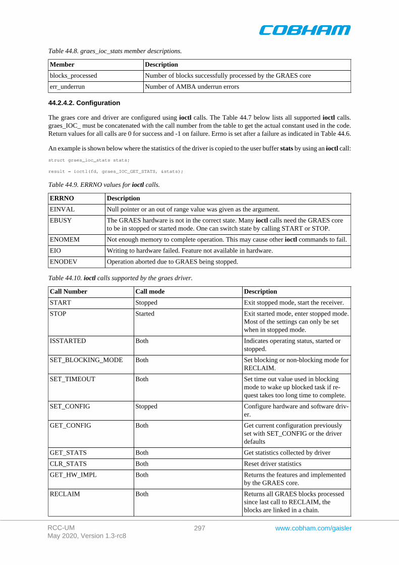
RCC-UMMay 2020, Version 1.3-rc8
297 www.cobham.com/gaisler
Table 44.8. graes_ioc_stats member descriptions.
Member Description
blocks_processed Number of blocks successfully processed by the GRAES core
err_underrun Number of AMBA underrun errors
44.2.4.2. Configuration
The graes core and driver are configured using ioctl calls. The Table 44.7 below lists all supported ioctl calls.graes_IOC_ must be concatenated with the call number from the table to get the actual constant used in the code.Return values for all calls are 0 for success and -1 on failure. Errno is set after a failure as indicated in Table 44.6.
An example is shown below where the statistics of the driver is copied to the user buffer stats by using an ioctl call:
struct graes_ioc_stats stats;
result = ioctl(fd, graes_IOC_GET_STATS, &stats);
Table 44.9. ERRNO values for ioctl calls.
ERRNO Description
EINVAL Null pointer or an out of range value was given as the argument.
EBUSY The GRAES hardware is not in the correct state. Many ioctl calls need the GRAES coreto be in stopped or started mode. One can switch state by calling START or STOP.
ENOMEM Not enough memory to complete operation. This may cause other ioctl commands to fail.
EIO Writing to hardware failed. Feature not available in hardware.
ENODEV Operation aborted due to GRAES being stopped.
Table 44.10. ioctl calls supported by the graes driver.
Call Number Call mode Description
START Stopped Exit stopped mode, start the receiver.
STOP Started Exit started mode, enter stopped mode.Most of the settings can only be setwhen in stopped mode.
ISSTARTED Both Indicates operating status, started orstopped.
SET_BLOCKING_MODE Both Set blocking or non-blocking mode forRECLAIM.
SET_TIMEOUT Both Set time out value used in blockingmode to wake up blocked task if re-quest takes too long time to complete.
SET_CONFIG Stopped Configure hardware and software driv-er.
GET_CONFIG Both Get current configuration previouslyset with SET_CONFIG or the driverdefaults
GET_STATS Both Get statistics collected by driver
CLR_STATS Both Reset driver statistics
GET_HW_IMPL Both Returns the features and implementedby the GRAES core.
RECLAIM Both Returns all GRAES blocks processedsince last call to RECLAIM, theblocks are linked in a chain.

RCC-UMMay 2020, Version 1.3-rc8
298 www.cobham.com/gaisler
Call Number Call mode Description
ENCRYPT Started Add a chain of GRAES blocks to theen/decryption queue of the GRAESdriver.
44.2.4.2.1. START
This ioctl command enables the GRAES core and changes the driver's operating status to started. Settings previ-ously set by other ioctl commands are written to hardware just before starting processing.
44.2.4.2.2. STOP
This call makes the GRAES core leave started mode and enter stopped mode. After calling STOP further ioctlcommands such as ENCRYPT, RECLAIM, ISSTARTED, STOP will behave differently or result in error.
The command will fail if the GRAES driver already is in stopped mode.
44.2.4.2.3. ISSTARTED
Determines if driver and hardware is in started mode. Errno will be set to EBUSY in stopped mode and returnsuccessfully in started mode.
44.2.4.2.4. SET_BLOCKING_MODE
Changes the driver's GRAES_IOC_RECLAIM command behaviour. Two modes are available blocking mode andpolling mode, in polling mode the ioctl command RECLAIM always return directly even when no blocks areavailable. In blocking mode the task calling RECLAIM is blocked until at least one block can be reclaimed, it isalso possible to make the blocked task time out after some time setting the timeout value using the SET_CONFIGor SET_TIMEOUT ioctl commands.
The argument is set as as described in the table below.
Table 44.11. SET_BLOCKING_MODE ioctl arguments
Bit number Description
GRAES_BLKMODE_POLL Enables polling mode
GRAES_BLKMODE_BLK Enables blocking mode
The driver's default is polling mode.
Note that the blocking mode is implemented using the DMA de/encrypt block interrupt, changing theisr_desc_proc parameter of the SET_CONFIG command effects the blocking mode characteristics. For ex-ample, enabling interrupt generation every tenth GRAES block will cause the blocked task to be woken up aftermaximum ten blocks when going into blocked mode.
This command never fail.
44.2.4.2.5. SET_TIMEOUT
Sets the blocking mode time out value, instead of blocking for eternity the task will be woken up af-ter this time out expires. The time out value specifies the input to the RTEMS take semaphore operationrtems_semaphore_obtain(). See the RTEMS documentation for more information how to set the timeout value.
Note that this option has no effect in polling mode.
Note that this option is also set by SET_CONFIG.
This command never fail.

RCC-UMMay 2020, Version 1.3-rc8
299 www.cobham.com/gaisler
44.2.4.2.6. SET_CONFIG
Configures the driver and core. This call updates the configuration that will be used by the driver during theSTART command and during operation. Enabling features not implemented by the GRAES core will result in EIOerror when starting the GRAES driver. The hardware features available can be obtained by the GET_HW_IMPLcommand.
The input is a pointer to an initialized graes_ioc_config structure described in Section 44.2.4.2.1.
Note that the time out value and blocking mode can also be set with SET_TIMEOUT andSET_BLOCKING_MODE.
This call fail if the GRAES core is in started mode, in that case errno will be set to EBUSY, or if a NULL pointeris given as argument, in that case errno will be set to EINVAL.
44.2.4.2.7. GET_CONFIG
Returns the current configuration of the driver and hardware. The current configuration is either the driver andhardware defaults or the configuration previously set by the SET_CONFIG command.
The input to this ioctl command is a pointer to a data area of at least the size of a graes_ioc_config struc-ture. The data area will be updated according to the graes_ioc_config data structure described in Sec-tion 44.2.4.2.1.
This command only fail if the pointer argument is invalid.
44.2.4.2.8. GET_STATS
This command copies the driver's internal statistics counters to a user provided data area. The format of the datawritten is described in the data structure subsection. See the graes_ioc_stats data structure.
The call will fail if the pointer to the data is invalid.
44.2.4.2.9. CLR_STATS
This command reset the driver's internal statistics counters.
This command never fail.
44.2.4.2.10. GET_HW_IMPL
This command copies the GRAES core's features implemented to a user provided data area. The format of thedata written is described in the data structure subsection. See the graes_ioc_hw data structure.
Knowing the features supported by hardware can be used to make software run on multiple implementations ofthe GRAES core.
The call will fail if the pointer to the data is invalid.
44.2.4.2.11. RECLAIM
Returns processed GRAES block to user. All blocks returned has been provided by the user in previous calls toENCRYPT, and need not all to have been successfully de/encrypted. RECLAIM can be configured to operate inpolling mode, blocking mode and blocking mode with a time out. In polling mode the task always returns with orwithout processed packets, in blocking mode the task is blocked until at least one packet has been processed. Seethe ioctl command SET_CONFIG and SET_BLOCKING_MODE to change mode of the RECLAIM command.
RECLAIM stores a linked list of processed GRAES blocks into the data area pointed to by the user argument.The format for the stored data follows the layout of the graes_list structure described in Section 44.2.2. Thegraes_list structure holds the first and last GRAES block processed by the driver. The flags field indicatesif the block was received or if errors were experienced during processing of this packet. See Table 44.6 for flagsdetails.
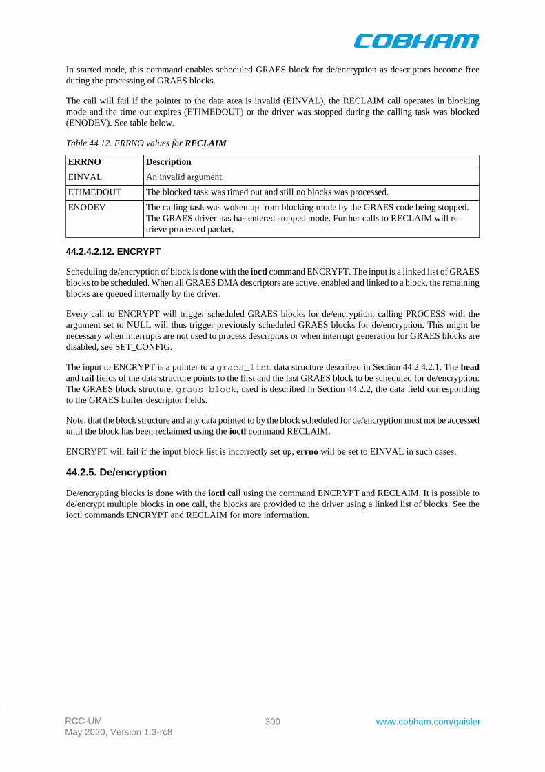
RCC-UMMay 2020, Version 1.3-rc8
300 www.cobham.com/gaisler
In started mode, this command enables scheduled GRAES block for de/encryption as descriptors become freeduring the processing of GRAES blocks.
The call will fail if the pointer to the data area is invalid (EINVAL), the RECLAIM call operates in blockingmode and the time out expires (ETIMEDOUT) or the driver was stopped during the calling task was blocked(ENODEV). See table below.
Table 44.12. ERRNO values for RECLAIM
ERRNO Description
EINVAL An invalid argument.
ETIMEDOUT The blocked task was timed out and still no blocks was processed.
ENODEV The calling task was woken up from blocking mode by the GRAES code being stopped.The GRAES driver has has entered stopped mode. Further calls to RECLAIM will re-trieve processed packet.
44.2.4.2.12. ENCRYPT
Scheduling de/encryption of block is done with the ioctl command ENCRYPT. The input is a linked list of GRAESblocks to be scheduled. When all GRAES DMA descriptors are active, enabled and linked to a block, the remainingblocks are queued internally by the driver.
Every call to ENCRYPT will trigger scheduled GRAES blocks for de/encryption, calling PROCESS with theargument set to NULL will thus trigger previously scheduled GRAES blocks for de/encryption. This might benecessary when interrupts are not used to process descriptors or when interrupt generation for GRAES blocks aredisabled, see SET_CONFIG.
The input to ENCRYPT is a pointer to a graes_list data structure described in Section 44.2.4.2.1. The headand tail fields of the data structure points to the first and the last GRAES block to be scheduled for de/encryption.The GRAES block structure, graes_block, used is described in Section 44.2.2, the data field correspondingto the GRAES buffer descriptor fields.
Note, that the block structure and any data pointed to by the block scheduled for de/encryption must not be accesseduntil the block has been reclaimed using the ioctl command RECLAIM.
ENCRYPT will fail if the input block list is incorrectly set up, errno will be set to EINVAL in such cases.
44.2.5. De/encryption
De/encrypting blocks is done with the ioctl call using the command ENCRYPT and RECLAIM. It is possible tode/encrypt multiple blocks in one call, the blocks are provided to the driver using a linked list of blocks. See theioctl commands ENCRYPT and RECLAIM for more information.
RCC-UMMay 2020, Version 1.3-rc8
301 www.cobham.com/gaisler
Chapter 45. AHB Status register driver
45.1. Overview
This section describes the GRLIB AHBSTAT device driver that is available in the RCC distribution.
45.2. Driver sources
The driver sources and definitions are listed in the table below, the path is given relative to the RTEMS sourcetree rtems-5/c/src/lib/libbsp/sparc.
Table 45.1. Source Location
Filename Description
shared/include/ahbstat.h AHBSTAT user interface definition
shared/amba/ahbstat.c AHBSTAT driver implementation
45.3. Driver registration
The function ahbstat_register_drv whose prototype is provided in ahbstat.h is used for registering thedriver:
ahbstat_register_drv();
45.4. Operation
The AHBSTAT device can generate an interrupt on AHB error responses and other access errors (correctableerrors for example) by monitoring AMBA AHB bus signals. The signals are generated from FT-cores at the timethe correctable AMBA access takes place. The software may through interrupt and by looking at the AHBSTATregisters determine what type of error happened and the address accessed.
This driver initializes the AHBSTAT and enables interrupt handling on initialization. A default interrupt handler isinstalled which prints detected access error to the system console using printk() . The default interrupt handleralso reenables AHB bus monitoring in order to detect the next error. The user may override the default interrupthandler to do custom handling and some function exists to make accesses to the AHBSTAT easier.
45.5. User interface
The driver provides the ability to assign a custom interrupt error handler and through a simple function interfaceread the last error that occurred which as been sampled at the last interrupt.
45.5.1. Assigning a custom interrupt handler
A custom interrupt handler can be installed to handle events as a result of AMBA errors detected. The AHBSTATdriver has a weak function pointer which can be overridden at compile time or at runtime. Below is the prototypefor the user interrupt handler.
int (*ahbstat_error)( int minor, struct ahbstat_regs *regs, uint32_t status, uint32_t failing_address )
The function is called from the AHBSTAT Interrupt Service Routine (ISR). The AHBSTAT driver will providethe custom function with four arguments described in the table below. The return value is interpreted as a 2-bitbit-mask, where bit zero turns on or off the default printout and the second bit controls whether the AHBSTATis to be reenabled or not.
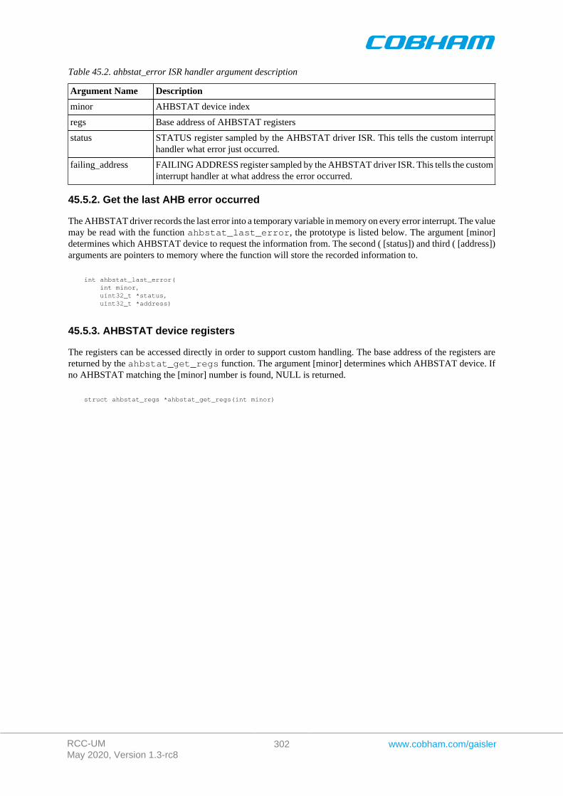
RCC-UMMay 2020, Version 1.3-rc8
302 www.cobham.com/gaisler
Table 45.2. ahbstat_error ISR handler argument description
Argument Name Description
minor AHBSTAT device index
regs Base address of AHBSTAT registers
status STATUS register sampled by the AHBSTAT driver ISR. This tells the custom interrupthandler what error just occurred.
failing_address FAILING ADDRESS register sampled by the AHBSTAT driver ISR. This tells the custominterrupt handler at what address the error occurred.
45.5.2. Get the last AHB error occurred
The AHBSTAT driver records the last error into a temporary variable in memory on every error interrupt. The valuemay be read with the function ahbstat_last_error, the prototype is listed below. The argument [minor]determines which AHBSTAT device to request the information from. The second ( [status]) and third ( [address])arguments are pointers to memory where the function will store the recorded information to.
int ahbstat_last_error( int minor, uint32_t *status, uint32_t *address)
45.5.3. AHBSTAT device registers
The registers can be accessed directly in order to support custom handling. The base address of the registers arereturned by the ahbstat_get_regs function. The argument [minor] determines which AHBSTAT device. Ifno AHBSTAT matching the [minor] number is found, NULL is returned.
struct ahbstat_regs *ahbstat_get_regs(int minor)
RCC-UMMay 2020, Version 1.3-rc8
303 www.cobham.com/gaisler
Chapter 46. L2CACHE driver
46.1. Introduction
This section describes the L2CACHE driver for SPARC/LEON processors.
46.1.1. Hardware Support
The L2CACHE core hardware interface is documented in the GRIP Core User's manual. Below is a list of themajor hardware features it supports:
• EDAC.• Hardware scrubber.• Split transactions.• Interrupt generation.• Locked ways.• Memory Type Range Registers.• Multiple write policies.• Multiple replacement policies.• Multiple flushing operations.
46.1.2. Driver sources
The driver sources and definitions are listed in the table below, the path is given relative to the RTEMS sourcetree rtems-5/c/src/lib/libbsp/sparc.
Table 46.1. L2CACHE driver source location
Location Description
shared/include/l2c.h L2CACHE user interface definition
.../libbsp/sparc/shared/l2c/l2c.c L2CACHE driver implementation
46.1.3. Examples
There is a simple example available that uses the L2CACHE to set the MTRR register for a pci transfer. The exam-ple is part of the RCC distribution, it can be found under /opt/rtems-5/src/samples/pci/pci_demo/test.c.
46.2. Software design overview
The driver has been implemented using the Driver Manager Framework. The driver provides a kernel functioninterface, an API, rather than implementing a IO system device. The API is not designed for multi-threadding,i.e. multiple threads operating on the driver independently. The driver does not contain any lock or protectionfor SMP environments. Changing the L2 cache configuration is not intended to be done extensively at runtimeor independently of the rest of the system, since it usually has a big impact on the rest of the system. Thereforethe user must take care of any impact that the different actions might have on other parts of the system (such asthreads, CPUs, DMAs, ...).
46.2.1. Driver usage
The driver provides a set of functions that allow to configure the L2 cache. The following list summarizes theavailable actions.
• Enable/disable the L2 cache (see Section 46.3.3).• Enable/disable EDAC (see Section 46.3.4).• Using the hardware scrubber (see Section 46.3.5).• Enable/disable split transactions (see Section 46.3.6).• Change write policy (see Section 46.3.7).• Change replacement policy (see Section 46.3.8).

RCC-UMMay 2020, Version 1.3-rc8
304 www.cobham.com/gaisler
• Lock ways of the L2 cache (see Section 46.3.9).• Set up Memory Type Range Registers (MTRR) (see Section 46.3.10).• Check L2 cache configuration status (see Section 46.3.11).
The driver also provides a set of functions to flush the cache (see Section 46.3.2). These functions can flush anaddress range, a cache line, a cache way or the whole cache. Each flush operation is defined by the differentoptions in Section 46.2.2.
When dealing with errors, the drivers provides two different interfaces:
• Interrupts (see Section 46.3.12): Allows the user to install an Interrupt Service Routine (ISR) that will beexecuted whenever an error occurs
• Polling (see Section 46.3.13): Allows the user to poll the error status to check if an error (or multiple) haveoccurred.
Only one of these interfaces can be used at a given time.
The different errors that the L2 cache can report are:
• Backend AHB error.• Write protection hit.• Uncorrectable EDAC error.• Correctable EDAC error.
46.2.2. Flush operationsThere are three types of flush operations:
• Invalidate contents: Set valid bit to 0. This means that any contents will be removed and therefore any newaccess to that contents will result in a cache miss. If any of the contents was in dirty state, that informationwill be lost.
• Writeback contents: Write all dirty contents to the memory. This means that any content in dirty state will bewriten back to memory, therefore consistency between memory and cache contents is achieved.
• Invalidate and Writeback contents: Writeback contents and then invalidate them.
46.2.3. Initialization
During early initialization when the operating system boots the L2CACHE driver, the driver does not modify thehardware state of the L2 cache.
46.3. L2CACHE user interface
46.3.1. Return values
L2CACHE_ERR_OK L2CACHE_ERR_EINVAL L2CACHE_ERR_NOINIT L2CACHE_ERR_TOOMANY L2CACHE_ERR_ERROR
All the driver function calls return the following values when an error occurred:
• L2CACHE_ERR_OK - Successful execution.• L2CACHE_ERR_EINVAL - Invalid input parameter. One of the input values checks failed.• L2CACHE_ERR_NOINIT - Driver not initialized.• L2CACHE_ERR_TOOMANY - Maximum index exceeded.• L2CACHE_ERR_ERROR - Internal error. Can have different causes.
Some functions also return a positive value upon successful execution, such as the status of the cache or the errorregister.
46.3.2. Flushing the L2 cache
int l2cache_flush(int flush); int l2cache_flush_address(uint32_t addr, int size, int flush);
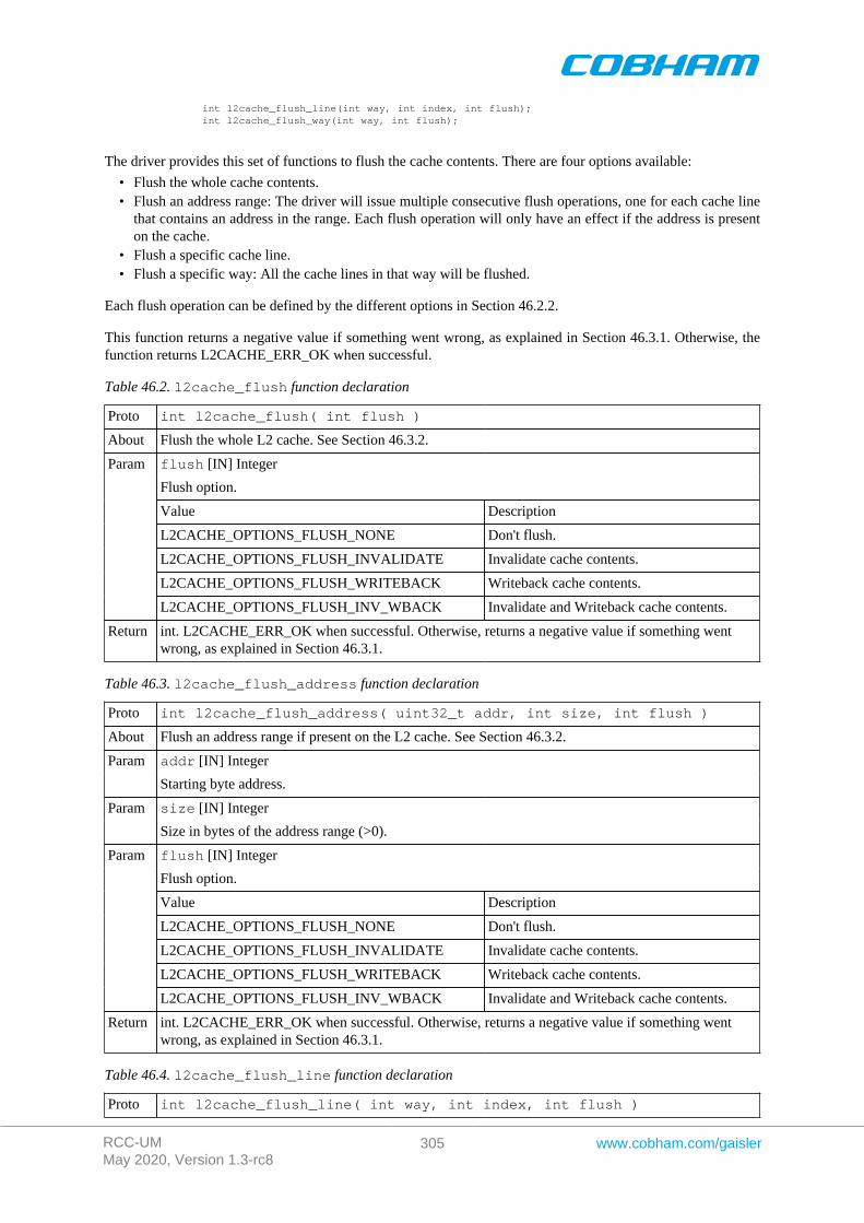
RCC-UMMay 2020, Version 1.3-rc8
305 www.cobham.com/gaisler
int l2cache_flush_line(int way, int index, int flush); int l2cache_flush_way(int way, int flush);
The driver provides this set of functions to flush the cache contents. There are four options available:
• Flush the whole cache contents.• Flush an address range: The driver will issue multiple consecutive flush operations, one for each cache line
that contains an address in the range. Each flush operation will only have an effect if the address is presenton the cache.
• Flush a specific cache line.• Flush a specific way: All the cache lines in that way will be flushed.
Each flush operation can be defined by the different options in Section 46.2.2.
This function returns a negative value if something went wrong, as explained in Section 46.3.1. Otherwise, thefunction returns L2CACHE_ERR_OK when successful.
Table 46.2. l2cache_flush function declaration
Proto int l2cache_flush( int flush )
About Flush the whole L2 cache. See Section 46.3.2.
flush [IN] Integer
Flush option.
Value Description
L2CACHE_OPTIONS_FLUSH_NONE Don't flush.
L2CACHE_OPTIONS_FLUSH_INVALIDATE Invalidate cache contents.
L2CACHE_OPTIONS_FLUSH_WRITEBACK Writeback cache contents.
Param
L2CACHE_OPTIONS_FLUSH_INV_WBACK Invalidate and Writeback cache contents.
Return int. L2CACHE_ERR_OK when successful. Otherwise, returns a negative value if something wentwrong, as explained in Section 46.3.1.
Table 46.3. l2cache_flush_address function declaration
Proto int l2cache_flush_address( uint32_t addr, int size, int flush )
About Flush an address range if present on the L2 cache. See Section 46.3.2.
addr [IN] IntegerParam
Starting byte address.
size [IN] IntegerParam
Size in bytes of the address range (>0).
flush [IN] Integer
Flush option.
Value Description
L2CACHE_OPTIONS_FLUSH_NONE Don't flush.
L2CACHE_OPTIONS_FLUSH_INVALIDATE Invalidate cache contents.
L2CACHE_OPTIONS_FLUSH_WRITEBACK Writeback cache contents.
Param
L2CACHE_OPTIONS_FLUSH_INV_WBACK Invalidate and Writeback cache contents.
Return int. L2CACHE_ERR_OK when successful. Otherwise, returns a negative value if something wentwrong, as explained in Section 46.3.1.
Table 46.4. l2cache_flush_line function declaration
Proto int l2cache_flush_line( int way, int index, int flush )
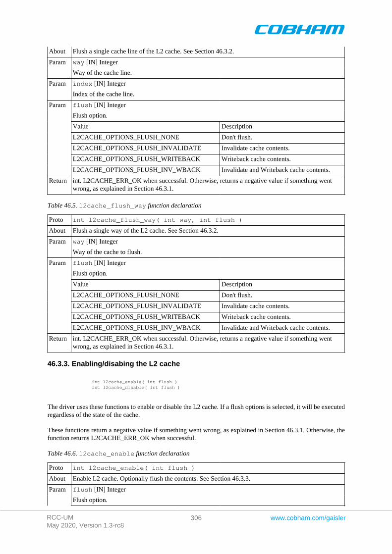
RCC-UMMay 2020, Version 1.3-rc8
306 www.cobham.com/gaisler
About Flush a single cache line of the L2 cache. See Section 46.3.2.
way [IN] IntegerParam
Way of the cache line.
index [IN] IntegerParam
Index of the cache line.
flush [IN] Integer
Flush option.
Value Description
L2CACHE_OPTIONS_FLUSH_NONE Don't flush.
L2CACHE_OPTIONS_FLUSH_INVALIDATE Invalidate cache contents.
L2CACHE_OPTIONS_FLUSH_WRITEBACK Writeback cache contents.
Param
L2CACHE_OPTIONS_FLUSH_INV_WBACK Invalidate and Writeback cache contents.
Return int. L2CACHE_ERR_OK when successful. Otherwise, returns a negative value if something wentwrong, as explained in Section 46.3.1.
Table 46.5. l2cache_flush_way function declaration
Proto int l2cache_flush_way( int way, int flush )
About Flush a single way of the L2 cache. See Section 46.3.2.
way [IN] IntegerParam
Way of the cache to flush.
flush [IN] Integer
Flush option.
Value Description
L2CACHE_OPTIONS_FLUSH_NONE Don't flush.
L2CACHE_OPTIONS_FLUSH_INVALIDATE Invalidate cache contents.
L2CACHE_OPTIONS_FLUSH_WRITEBACK Writeback cache contents.
Param
L2CACHE_OPTIONS_FLUSH_INV_WBACK Invalidate and Writeback cache contents.
Return int. L2CACHE_ERR_OK when successful. Otherwise, returns a negative value if something wentwrong, as explained in Section 46.3.1.
46.3.3. Enabling/disabing the L2 cache
int l2cache_enable( int flush ) int l2cache_disable( int flush )
The driver uses these functions to enable or disable the L2 cache. If a flush options is selected, it will be executedregardless of the state of the cache.
These functions return a negative value if something went wrong, as explained in Section 46.3.1. Otherwise, thefunction returns L2CACHE_ERR_OK when successful.
Table 46.6. l2cache_enable function declaration
Proto int l2cache_enable( int flush )
About Enable L2 cache. Optionally flush the contents. See Section 46.3.3.
flush [IN] IntegerParam
Flush option.
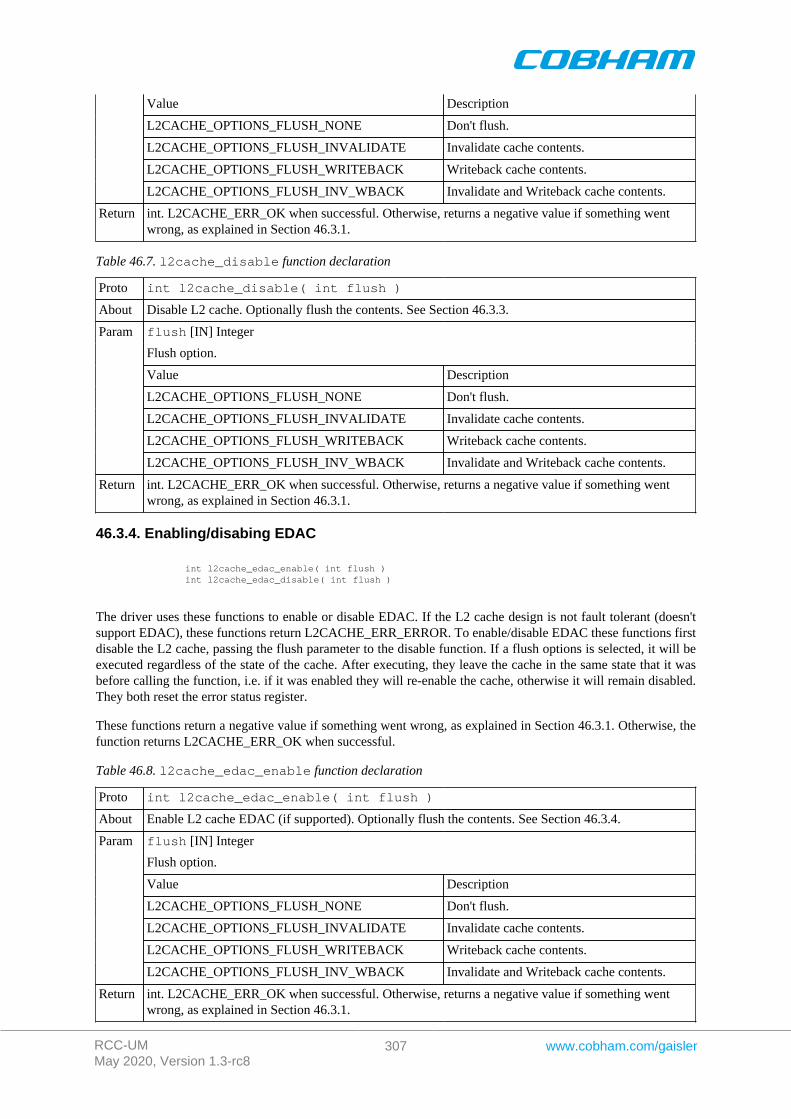
RCC-UMMay 2020, Version 1.3-rc8
307 www.cobham.com/gaisler
Value Description
L2CACHE_OPTIONS_FLUSH_NONE Don't flush.
L2CACHE_OPTIONS_FLUSH_INVALIDATE Invalidate cache contents.
L2CACHE_OPTIONS_FLUSH_WRITEBACK Writeback cache contents.
L2CACHE_OPTIONS_FLUSH_INV_WBACK Invalidate and Writeback cache contents.
Return int. L2CACHE_ERR_OK when successful. Otherwise, returns a negative value if something wentwrong, as explained in Section 46.3.1.
Table 46.7. l2cache_disable function declaration
Proto int l2cache_disable( int flush )
About Disable L2 cache. Optionally flush the contents. See Section 46.3.3.
flush [IN] Integer
Flush option.
Value Description
L2CACHE_OPTIONS_FLUSH_NONE Don't flush.
L2CACHE_OPTIONS_FLUSH_INVALIDATE Invalidate cache contents.
L2CACHE_OPTIONS_FLUSH_WRITEBACK Writeback cache contents.
Param
L2CACHE_OPTIONS_FLUSH_INV_WBACK Invalidate and Writeback cache contents.
Return int. L2CACHE_ERR_OK when successful. Otherwise, returns a negative value if something wentwrong, as explained in Section 46.3.1.
46.3.4. Enabling/disabing EDAC
int l2cache_edac_enable( int flush ) int l2cache_edac_disable( int flush )
The driver uses these functions to enable or disable EDAC. If the L2 cache design is not fault tolerant (doesn'tsupport EDAC), these functions return L2CACHE_ERR_ERROR. To enable/disable EDAC these functions firstdisable the L2 cache, passing the flush parameter to the disable function. If a flush options is selected, it will beexecuted regardless of the state of the cache. After executing, they leave the cache in the same state that it wasbefore calling the function, i.e. if it was enabled they will re-enable the cache, otherwise it will remain disabled.They both reset the error status register.
These functions return a negative value if something went wrong, as explained in Section 46.3.1. Otherwise, thefunction returns L2CACHE_ERR_OK when successful.
Table 46.8. l2cache_edac_enable function declaration
Proto int l2cache_edac_enable( int flush )
About Enable L2 cache EDAC (if supported). Optionally flush the contents. See Section 46.3.4.
flush [IN] Integer
Flush option.
Value Description
L2CACHE_OPTIONS_FLUSH_NONE Don't flush.
L2CACHE_OPTIONS_FLUSH_INVALIDATE Invalidate cache contents.
L2CACHE_OPTIONS_FLUSH_WRITEBACK Writeback cache contents.
Param
L2CACHE_OPTIONS_FLUSH_INV_WBACK Invalidate and Writeback cache contents.
Return int. L2CACHE_ERR_OK when successful. Otherwise, returns a negative value if something wentwrong, as explained in Section 46.3.1.
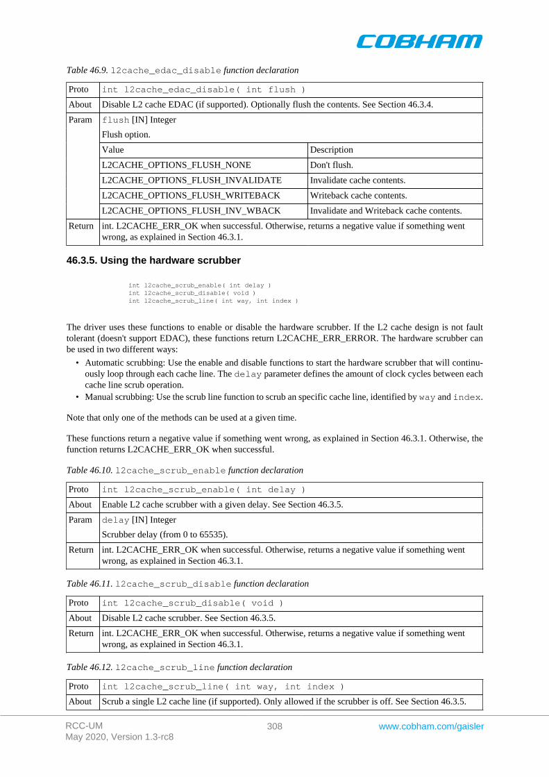
RCC-UMMay 2020, Version 1.3-rc8
308 www.cobham.com/gaisler
Table 46.9. l2cache_edac_disable function declaration
Proto int l2cache_edac_disable( int flush )
About Disable L2 cache EDAC (if supported). Optionally flush the contents. See Section 46.3.4.
flush [IN] Integer
Flush option.
Value Description
L2CACHE_OPTIONS_FLUSH_NONE Don't flush.
L2CACHE_OPTIONS_FLUSH_INVALIDATE Invalidate cache contents.
L2CACHE_OPTIONS_FLUSH_WRITEBACK Writeback cache contents.
Param
L2CACHE_OPTIONS_FLUSH_INV_WBACK Invalidate and Writeback cache contents.
Return int. L2CACHE_ERR_OK when successful. Otherwise, returns a negative value if something wentwrong, as explained in Section 46.3.1.
46.3.5. Using the hardware scrubber
int l2cache_scrub_enable( int delay ) int l2cache_scrub_disable( void ) int l2cache_scrub_line( int way, int index )
The driver uses these functions to enable or disable the hardware scrubber. If the L2 cache design is not faulttolerant (doesn't support EDAC), these functions return L2CACHE_ERR_ERROR. The hardware scrubber canbe used in two different ways:
• Automatic scrubbing: Use the enable and disable functions to start the hardware scrubber that will continu-ously loop through each cache line. The delay parameter defines the amount of clock cycles between eachcache line scrub operation.
• Manual scrubbing: Use the scrub line function to scrub an specific cache line, identified by way and index.
Note that only one of the methods can be used at a given time.
These functions return a negative value if something went wrong, as explained in Section 46.3.1. Otherwise, thefunction returns L2CACHE_ERR_OK when successful.
Table 46.10. l2cache_scrub_enable function declaration
Proto int l2cache_scrub_enable( int delay )
About Enable L2 cache scrubber with a given delay. See Section 46.3.5.
delay [IN] IntegerParam
Scrubber delay (from 0 to 65535).
Return int. L2CACHE_ERR_OK when successful. Otherwise, returns a negative value if something wentwrong, as explained in Section 46.3.1.
Table 46.11. l2cache_scrub_disable function declaration
Proto int l2cache_scrub_disable( void )
About Disable L2 cache scrubber. See Section 46.3.5.
Return int. L2CACHE_ERR_OK when successful. Otherwise, returns a negative value if something wentwrong, as explained in Section 46.3.1.
Table 46.12. l2cache_scrub_line function declaration
Proto int l2cache_scrub_line( int way, int index )
About Scrub a single L2 cache line (if supported). Only allowed if the scrubber is off. See Section 46.3.5.
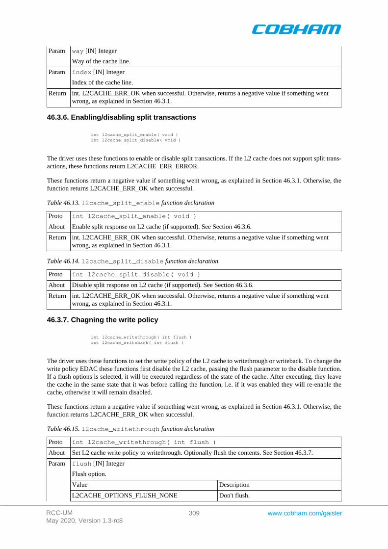
RCC-UMMay 2020, Version 1.3-rc8
309 www.cobham.com/gaisler
way [IN] IntegerParam
Way of the cache line.
index [IN] IntegerParam
Index of the cache line.
Return int. L2CACHE_ERR_OK when successful. Otherwise, returns a negative value if something wentwrong, as explained in Section 46.3.1.
46.3.6. Enabling/disabling split transactions
int l2cache_split_enable( void ) int l2cache_split_disable( void )
The driver uses these functions to enable or disable split transactions. If the L2 cache does not support split trans-actions, these functions return L2CACHE_ERR_ERROR.
These functions return a negative value if something went wrong, as explained in Section 46.3.1. Otherwise, thefunction returns L2CACHE_ERR_OK when successful.
Table 46.13. l2cache_split_enable function declaration
Proto int l2cache_split_enable( void )
About Enable split response on L2 cache (if supported). See Section 46.3.6.
Return int. L2CACHE_ERR_OK when successful. Otherwise, returns a negative value if something wentwrong, as explained in Section 46.3.1.
Table 46.14. l2cache_split_disable function declaration
Proto int l2cache_split_disable( void )
About Disable split response on L2 cache (if supported). See Section 46.3.6.
Return int. L2CACHE_ERR_OK when successful. Otherwise, returns a negative value if something wentwrong, as explained in Section 46.3.1.
46.3.7. Chagning the write policy
int l2cache_writethrough( int flush ) int l2cache_writeback( int flush )
The driver uses these functions to set the write policy of the L2 cache to writethrough or writeback. To change thewrite policy EDAC these functions first disable the L2 cache, passing the flush parameter to the disable function.If a flush options is selected, it will be executed regardless of the state of the cache. After executing, they leavethe cache in the same state that it was before calling the function, i.e. if it was enabled they will re-enable thecache, otherwise it will remain disabled.
These functions return a negative value if something went wrong, as explained in Section 46.3.1. Otherwise, thefunction returns L2CACHE_ERR_OK when successful.
Table 46.15. l2cache_writethrough function declaration
Proto int l2cache_writethrough( int flush )
About Set L2 cache write policy to writethrough. Optionally flush the contents. See Section 46.3.7.
flush [IN] Integer
Flush option.
Value Description
Param
L2CACHE_OPTIONS_FLUSH_NONE Don't flush.
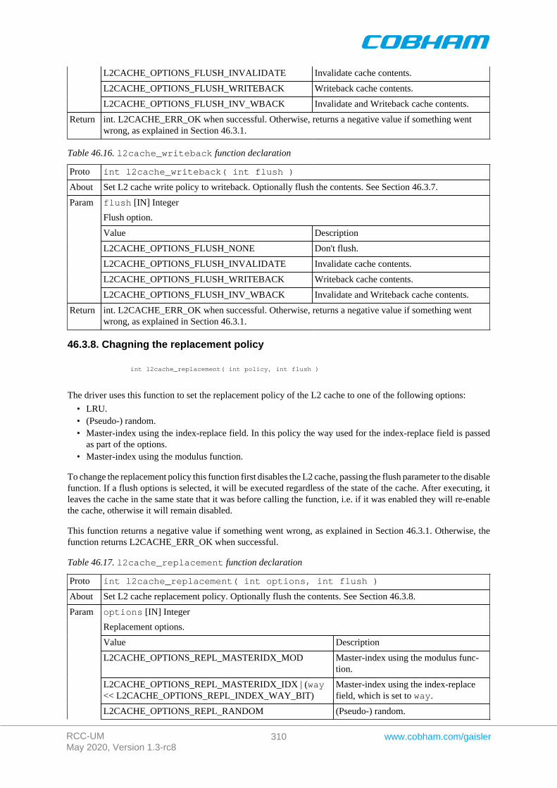
RCC-UMMay 2020, Version 1.3-rc8
310 www.cobham.com/gaisler
L2CACHE_OPTIONS_FLUSH_INVALIDATE Invalidate cache contents.
L2CACHE_OPTIONS_FLUSH_WRITEBACK Writeback cache contents.
L2CACHE_OPTIONS_FLUSH_INV_WBACK Invalidate and Writeback cache contents.
Return int. L2CACHE_ERR_OK when successful. Otherwise, returns a negative value if something wentwrong, as explained in Section 46.3.1.
Table 46.16. l2cache_writeback function declaration
Proto int l2cache_writeback( int flush )
About Set L2 cache write policy to writeback. Optionally flush the contents. See Section 46.3.7.
flush [IN] Integer
Flush option.
Value Description
L2CACHE_OPTIONS_FLUSH_NONE Don't flush.
L2CACHE_OPTIONS_FLUSH_INVALIDATE Invalidate cache contents.
L2CACHE_OPTIONS_FLUSH_WRITEBACK Writeback cache contents.
Param
L2CACHE_OPTIONS_FLUSH_INV_WBACK Invalidate and Writeback cache contents.
Return int. L2CACHE_ERR_OK when successful. Otherwise, returns a negative value if something wentwrong, as explained in Section 46.3.1.
46.3.8. Chagning the replacement policy
int l2cache_replacement( int policy, int flush )
The driver uses this function to set the replacement policy of the L2 cache to one of the following options:
• LRU.• (Pseudo-) random.• Master-index using the index-replace field. In this policy the way used for the index-replace field is passed
as part of the options.• Master-index using the modulus function.
To change the replacement policy this function first disables the L2 cache, passing the flush parameter to the disablefunction. If a flush options is selected, it will be executed regardless of the state of the cache. After executing, itleaves the cache in the same state that it was before calling the function, i.e. if it was enabled they will re-enablethe cache, otherwise it will remain disabled.
This function returns a negative value if something went wrong, as explained in Section 46.3.1. Otherwise, thefunction returns L2CACHE_ERR_OK when successful.
Table 46.17. l2cache_replacement function declaration
Proto int l2cache_replacement( int options, int flush )
About Set L2 cache replacement policy. Optionally flush the contents. See Section 46.3.8.
options [IN] Integer
Replacement options.
Value Description
L2CACHE_OPTIONS_REPL_MASTERIDX_MOD Master-index using the modulus func-tion.
L2CACHE_OPTIONS_REPL_MASTERIDX_IDX | (way<< L2CACHE_OPTIONS_REPL_INDEX_WAY_BIT)
Master-index using the index-replacefield, which is set to way.
Param
L2CACHE_OPTIONS_REPL_RANDOM (Pseudo-) random.
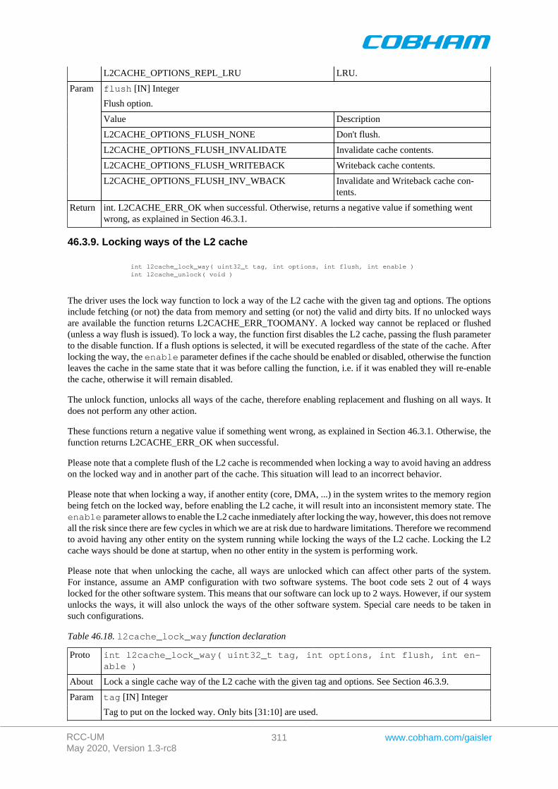
RCC-UMMay 2020, Version 1.3-rc8
311 www.cobham.com/gaisler
L2CACHE_OPTIONS_REPL_LRU LRU.
flush [IN] Integer
Flush option.
Value Description
L2CACHE_OPTIONS_FLUSH_NONE Don't flush.
L2CACHE_OPTIONS_FLUSH_INVALIDATE Invalidate cache contents.
L2CACHE_OPTIONS_FLUSH_WRITEBACK Writeback cache contents.
Param
L2CACHE_OPTIONS_FLUSH_INV_WBACK Invalidate and Writeback cache con-tents.
Return int. L2CACHE_ERR_OK when successful. Otherwise, returns a negative value if something wentwrong, as explained in Section 46.3.1.
46.3.9. Locking ways of the L2 cache
int l2cache_lock_way( uint32_t tag, int options, int flush, int enable ) int l2cache_unlock( void )
The driver uses the lock way function to lock a way of the L2 cache with the given tag and options. The optionsinclude fetching (or not) the data from memory and setting (or not) the valid and dirty bits. If no unlocked waysare available the function returns L2CACHE_ERR_TOOMANY. A locked way cannot be replaced or flushed(unless a way flush is issued). To lock a way, the function first disables the L2 cache, passing the flush parameterto the disable function. If a flush options is selected, it will be executed regardless of the state of the cache. Afterlocking the way, the enable parameter defines if the cache should be enabled or disabled, otherwise the functionleaves the cache in the same state that it was before calling the function, i.e. if it was enabled they will re-enablethe cache, otherwise it will remain disabled.
The unlock function, unlocks all ways of the cache, therefore enabling replacement and flushing on all ways. Itdoes not perform any other action.
These functions return a negative value if something went wrong, as explained in Section 46.3.1. Otherwise, thefunction returns L2CACHE_ERR_OK when successful.
Please note that a complete flush of the L2 cache is recommended when locking a way to avoid having an addresson the locked way and in another part of the cache. This situation will lead to an incorrect behavior.
Please note that when locking a way, if another entity (core, DMA, ...) in the system writes to the memory regionbeing fetch on the locked way, before enabling the L2 cache, it will result into an inconsistent memory state. Theenable parameter allows to enable the L2 cache inmediately after locking the way, however, this does not removeall the risk since there are few cycles in which we are at risk due to hardware limitations. Therefore we recommendto avoid having any other entity on the system running while locking the ways of the L2 cache. Locking the L2cache ways should be done at startup, when no other entity in the system is performing work.
Please note that when unlocking the cache, all ways are unlocked which can affect other parts of the system.For instance, assume an AMP configuration with two software systems. The boot code sets 2 out of 4 wayslocked for the other software system. This means that our software can lock up to 2 ways. However, if our systemunlocks the ways, it will also unlock the ways of the other software system. Special care needs to be taken insuch configurations.
Table 46.18. l2cache_lock_way function declaration
Proto int l2cache_lock_way( uint32_t tag, int options, int flush, int en-able )
About Lock a single cache way of the L2 cache with the given tag and options. See Section 46.3.9.
tag [IN] IntegerParam
Tag to put on the locked way. Only bits [31:10] are used.
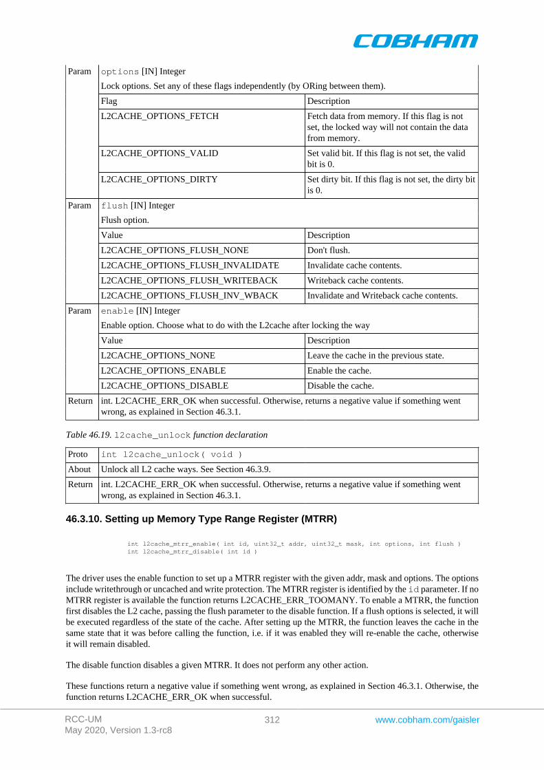
RCC-UMMay 2020, Version 1.3-rc8
312 www.cobham.com/gaisler
options [IN] Integer
Lock options. Set any of these flags independently (by ORing between them).
Flag Description
L2CACHE_OPTIONS_FETCH Fetch data from memory. If this flag is notset, the locked way will not contain the datafrom memory.
L2CACHE_OPTIONS_VALID Set valid bit. If this flag is not set, the validbit is 0.
Param
L2CACHE_OPTIONS_DIRTY Set dirty bit. If this flag is not set, the dirty bitis 0.
flush [IN] Integer
Flush option.
Value Description
L2CACHE_OPTIONS_FLUSH_NONE Don't flush.
L2CACHE_OPTIONS_FLUSH_INVALIDATE Invalidate cache contents.
L2CACHE_OPTIONS_FLUSH_WRITEBACK Writeback cache contents.
Param
L2CACHE_OPTIONS_FLUSH_INV_WBACK Invalidate and Writeback cache contents.
enable [IN] Integer
Enable option. Choose what to do with the L2cache after locking the way
Value Description
L2CACHE_OPTIONS_NONE Leave the cache in the previous state.
L2CACHE_OPTIONS_ENABLE Enable the cache.
Param
L2CACHE_OPTIONS_DISABLE Disable the cache.
Return int. L2CACHE_ERR_OK when successful. Otherwise, returns a negative value if something wentwrong, as explained in Section 46.3.1.
Table 46.19. l2cache_unlock function declaration
Proto int l2cache_unlock( void )
About Unlock all L2 cache ways. See Section 46.3.9.
Return int. L2CACHE_ERR_OK when successful. Otherwise, returns a negative value if something wentwrong, as explained in Section 46.3.1.
46.3.10. Setting up Memory Type Range Register (MTRR)
int l2cache_mtrr_enable( int id, uint32_t addr, uint32_t mask, int options, int flush ) int l2cache_mtrr_disable( int id )
The driver uses the enable function to set up a MTRR register with the given addr, mask and options. The optionsinclude writethrough or uncached and write protection. The MTRR register is identified by the id parameter. If noMTRR register is available the function returns L2CACHE_ERR_TOOMANY. To enable a MTRR, the functionfirst disables the L2 cache, passing the flush parameter to the disable function. If a flush options is selected, it willbe executed regardless of the state of the cache. After setting up the MTRR, the function leaves the cache in thesame state that it was before calling the function, i.e. if it was enabled they will re-enable the cache, otherwiseit will remain disabled.
The disable function disables a given MTRR. It does not perform any other action.
These functions return a negative value if something went wrong, as explained in Section 46.3.1. Otherwise, thefunction returns L2CACHE_ERR_OK when successful.
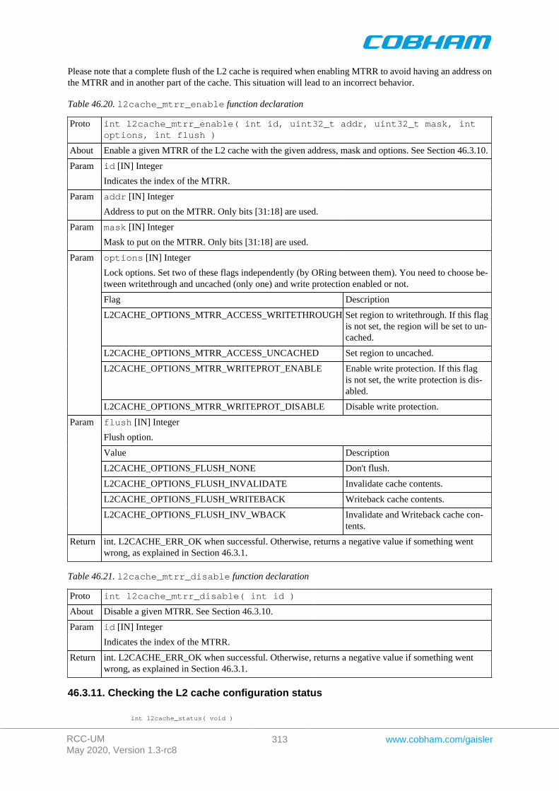
RCC-UMMay 2020, Version 1.3-rc8
313 www.cobham.com/gaisler
Please note that a complete flush of the L2 cache is required when enabling MTRR to avoid having an address onthe MTRR and in another part of the cache. This situation will lead to an incorrect behavior.
Table 46.20. l2cache_mtrr_enable function declaration
Proto int l2cache_mtrr_enable( int id, uint32_t addr, uint32_t mask, intoptions, int flush )
About Enable a given MTRR of the L2 cache with the given address, mask and options. See Section 46.3.10.
id [IN] IntegerParam
Indicates the index of the MTRR.
addr [IN] IntegerParam
Address to put on the MTRR. Only bits [31:18] are used.
mask [IN] IntegerParam
Mask to put on the MTRR. Only bits [31:18] are used.
options [IN] Integer
Lock options. Set two of these flags independently (by ORing between them). You need to choose be-tween writethrough and uncached (only one) and write protection enabled or not.
Flag Description
L2CACHE_OPTIONS_MTRR_ACCESS_WRITETHROUGH Set region to writethrough. If this flagis not set, the region will be set to un-cached.
L2CACHE_OPTIONS_MTRR_ACCESS_UNCACHED Set region to uncached.
L2CACHE_OPTIONS_MTRR_WRITEPROT_ENABLE Enable write protection. If this flagis not set, the write protection is dis-abled.
Param
L2CACHE_OPTIONS_MTRR_WRITEPROT_DISABLE Disable write protection.
flush [IN] Integer
Flush option.
Value Description
L2CACHE_OPTIONS_FLUSH_NONE Don't flush.
L2CACHE_OPTIONS_FLUSH_INVALIDATE Invalidate cache contents.
L2CACHE_OPTIONS_FLUSH_WRITEBACK Writeback cache contents.
Param
L2CACHE_OPTIONS_FLUSH_INV_WBACK Invalidate and Writeback cache con-tents.
Return int. L2CACHE_ERR_OK when successful. Otherwise, returns a negative value if something wentwrong, as explained in Section 46.3.1.
Table 46.21. l2cache_mtrr_disable function declaration
Proto int l2cache_mtrr_disable( int id )
About Disable a given MTRR. See Section 46.3.10.
id [IN] IntegerParam
Indicates the index of the MTRR.
Return int. L2CACHE_ERR_OK when successful. Otherwise, returns a negative value if something wentwrong, as explained in Section 46.3.1.
46.3.11. Checking the L2 cache configuration status
int l2cache_status( void )
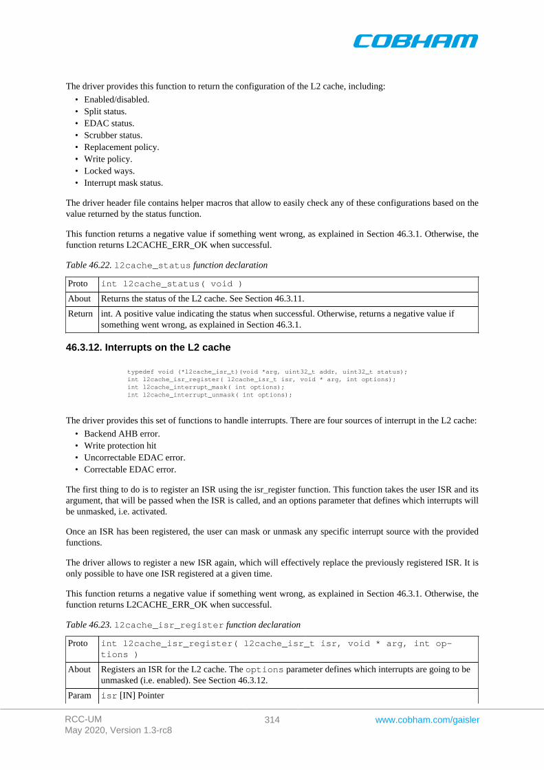
RCC-UMMay 2020, Version 1.3-rc8
314 www.cobham.com/gaisler
The driver provides this function to return the configuration of the L2 cache, including:
• Enabled/disabled.• Split status.• EDAC status.• Scrubber status.• Replacement policy.• Write policy.• Locked ways.• Interrupt mask status.
The driver header file contains helper macros that allow to easily check any of these configurations based on thevalue returned by the status function.
This function returns a negative value if something went wrong, as explained in Section 46.3.1. Otherwise, thefunction returns L2CACHE_ERR_OK when successful.
Table 46.22. l2cache_status function declaration
Proto int l2cache_status( void )
About Returns the status of the L2 cache. See Section 46.3.11.
Return int. A positive value indicating the status when successful. Otherwise, returns a negative value ifsomething went wrong, as explained in Section 46.3.1.
46.3.12. Interrupts on the L2 cache
typedef void (*l2cache_isr_t)(void *arg, uint32_t addr, uint32_t status); int l2cache_isr_register( l2cache_isr_t isr, void * arg, int options); int l2cache_interrupt_mask( int options); int l2cache_interrupt_unmask( int options);
The driver provides this set of functions to handle interrupts. There are four sources of interrupt in the L2 cache:
• Backend AHB error.• Write protection hit• Uncorrectable EDAC error.• Correctable EDAC error.
The first thing to do is to register an ISR using the isr_register function. This function takes the user ISR and itsargument, that will be passed when the ISR is called, and an options parameter that defines which interrupts willbe unmasked, i.e. activated.
Once an ISR has been registered, the user can mask or unmask any specific interrupt source with the providedfunctions.
The driver allows to register a new ISR again, which will effectively replace the previously registered ISR. It isonly possible to have one ISR registered at a given time.
This function returns a negative value if something went wrong, as explained in Section 46.3.1. Otherwise, thefunction returns L2CACHE_ERR_OK when successful.
Table 46.23. l2cache_isr_register function declaration
Proto int l2cache_isr_register( l2cache_isr_t isr, void * arg, int op-tions )
About Registers an ISR for the L2 cache. The options parameter defines which interrupts are going to beunmasked (i.e. enabled). See Section 46.3.12.
Param isr [IN] Pointer
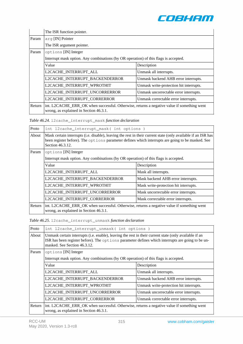
RCC-UMMay 2020, Version 1.3-rc8
315 www.cobham.com/gaisler
The ISR function pointer.
arg [IN] PointerParam
The ISR argument pointer.
options [IN] Integer
Interrupt mask option. Any combinations (by OR operation) of this flags is accepted.
Value Description
L2CACHE_INTERRUPT_ALL Unmask all interrupts.
L2CACHE_INTERRUPT_BACKENDERROR Unmask backend AHB error interrupts.
L2CACHE_INTERRUPT_WPROTHIT Unmask write-protection hit interrupts.
L2CACHE_INTERRUPT_UNCORRERROR Unmask uncorrectable error interrupts.
Param
L2CACHE_INTERRUPT_CORRERROR Unmask correctable error interrupts.
Return int. L2CACHE_ERR_OK when successful. Otherwise, returns a negative value if something wentwrong, as explained in Section 46.3.1.
Table 46.24. l2cache_interrupt_mask function declaration
Proto int l2cache_interrupt_mask( int options )
About Mask certain interrupts (i.e. disable), leaving the rest in their current state (only available if an ISR hasbeen register before). The options parameter defines which interrupts are going to be masked. SeeSection 46.3.12.
options [IN] Integer
Interrupt mask option. Any combinations (by OR operation) of this flags is accepted.
Value Description
L2CACHE_INTERRUPT_ALL Mask all interrupts.
L2CACHE_INTERRUPT_BACKENDERROR Mask backend AHB error interrupts.
L2CACHE_INTERRUPT_WPROTHIT Mask write-protection hit interrupts.
L2CACHE_INTERRUPT_UNCORRERROR Mask uncorrectable error interrupts.
Param
L2CACHE_INTERRUPT_CORRERROR Mask correctable error interrupts.
Return int. L2CACHE_ERR_OK when successful. Otherwise, returns a negative value if something wentwrong, as explained in Section 46.3.1.
Table 46.25. l2cache_interrupt_unmask function declaration
Proto int l2cache_interrupt_unmask( int options )
About Unmask certain interrupts (i.e. enable), leaving the rest in their current state (only available if anISR has been register before). The options parameter defines which interrupts are going to be un-masked. See Section 46.3.12.
options [IN] Integer
Interrupt mask option. Any combinations (by OR operation) of this flags is accepted.
Value Description
L2CACHE_INTERRUPT_ALL Unmask all interrupts.
L2CACHE_INTERRUPT_BACKENDERROR Unmask backend AHB error interrupts.
L2CACHE_INTERRUPT_WPROTHIT Unmask write-protection hit interrupts.
L2CACHE_INTERRUPT_UNCORRERROR Unmask uncorrectable error interrupts.
Param
L2CACHE_INTERRUPT_CORRERROR Unmask correctable error interrupts.
Return int. L2CACHE_ERR_OK when successful. Otherwise, returns a negative value if something wentwrong, as explained in Section 46.3.1.
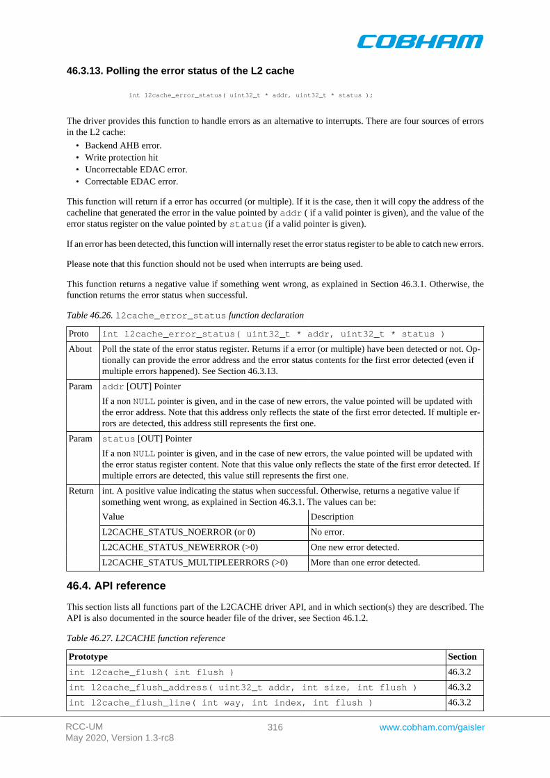
RCC-UMMay 2020, Version 1.3-rc8
316 www.cobham.com/gaisler
46.3.13. Polling the error status of the L2 cache
int l2cache_error_status( uint32_t * addr, uint32_t * status );
The driver provides this function to handle errors as an alternative to interrupts. There are four sources of errorsin the L2 cache:
• Backend AHB error.• Write protection hit• Uncorrectable EDAC error.• Correctable EDAC error.
This function will return if a error has occurred (or multiple). If it is the case, then it will copy the address of thecacheline that generated the error in the value pointed by addr ( if a valid pointer is given), and the value of theerror status register on the value pointed by status (if a valid pointer is given).
If an error has been detected, this function will internally reset the error status register to be able to catch new errors.
Please note that this function should not be used when interrupts are being used.
This function returns a negative value if something went wrong, as explained in Section 46.3.1. Otherwise, thefunction returns the error status when successful.
Table 46.26. l2cache_error_status function declaration
Proto int l2cache_error_status( uint32_t * addr, uint32_t * status )
About Poll the state of the error status register. Returns if a error (or multiple) have been detected or not. Op-tionally can provide the error address and the error status contents for the first error detected (even ifmultiple errors happened). See Section 46.3.13.
addr [OUT] PointerParam
If a non NULL pointer is given, and in the case of new errors, the value pointed will be updated withthe error address. Note that this address only reflects the state of the first error detected. If multiple er-rors are detected, this address still represents the first one.
status [OUT] PointerParam
If a non NULL pointer is given, and in the case of new errors, the value pointed will be updated withthe error status register content. Note that this value only reflects the state of the first error detected. Ifmultiple errors are detected, this value still represents the first one.
int. A positive value indicating the status when successful. Otherwise, returns a negative value ifsomething went wrong, as explained in Section 46.3.1. The values can be:
Value Description
L2CACHE_STATUS_NOERROR (or 0) No error.
L2CACHE_STATUS_NEWERROR (>0) One new error detected.
Return
L2CACHE_STATUS_MULTIPLEERRORS (>0) More than one error detected.
46.4. API reference
This section lists all functions part of the L2CACHE driver API, and in which section(s) they are described. TheAPI is also documented in the source header file of the driver, see Section 46.1.2.
Table 46.27. L2CACHE function reference
Prototype Section
int l2cache_flush( int flush ) 46.3.2
int l2cache_flush_address( uint32_t addr, int size, int flush ) 46.3.2
int l2cache_flush_line( int way, int index, int flush ) 46.3.2
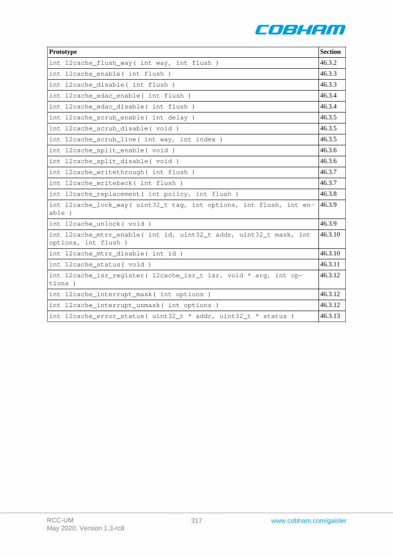
RCC-UMMay 2020, Version 1.3-rc8
317 www.cobham.com/gaisler
Prototype Section
int l2cache_flush_way( int way, int flush ) 46.3.2
int l2cache_enable( int flush ) 46.3.3
int l2cache_disable( int flush ) 46.3.3
int l2cache_edac_enable( int flush ) 46.3.4
int l2cache_edac_disable( int flush ) 46.3.4
int l2cache_scrub_enable( int delay ) 46.3.5
int l2cache_scrub_disable( void ) 46.3.5
int l2cache_scrub_line( int way, int index ) 46.3.5
int l2cache_split_enable( void ) 46.3.6
int l2cache_split_disable( void ) 46.3.6
int l2cache_writethrough( int flush ) 46.3.7
int l2cache_writeback( int flush ) 46.3.7
int l2cache_replacement( int policy, int flush ) 46.3.8
int l2cache_lock_way( uint32_t tag, int options, int flush, int en-able )
46.3.9
int l2cache_unlock( void ) 46.3.9
int l2cache_mtrr_enable( int id, uint32_t addr, uint32_t mask, intoptions, int flush )
46.3.10
int l2cache_mtrr_disable( int id ) 46.3.10
int l2cache_status( void ) 46.3.11
int l2cache_isr_register( l2cache_isr_t isr, void * arg, int op-tions )
46.3.12
int l2cache_interrupt_mask( int options ) 46.3.12
int l2cache_interrupt_unmask( int options ) 46.3.12
int l2cache_error_status( uint32_t * addr, uint32_t * status ) 46.3.13
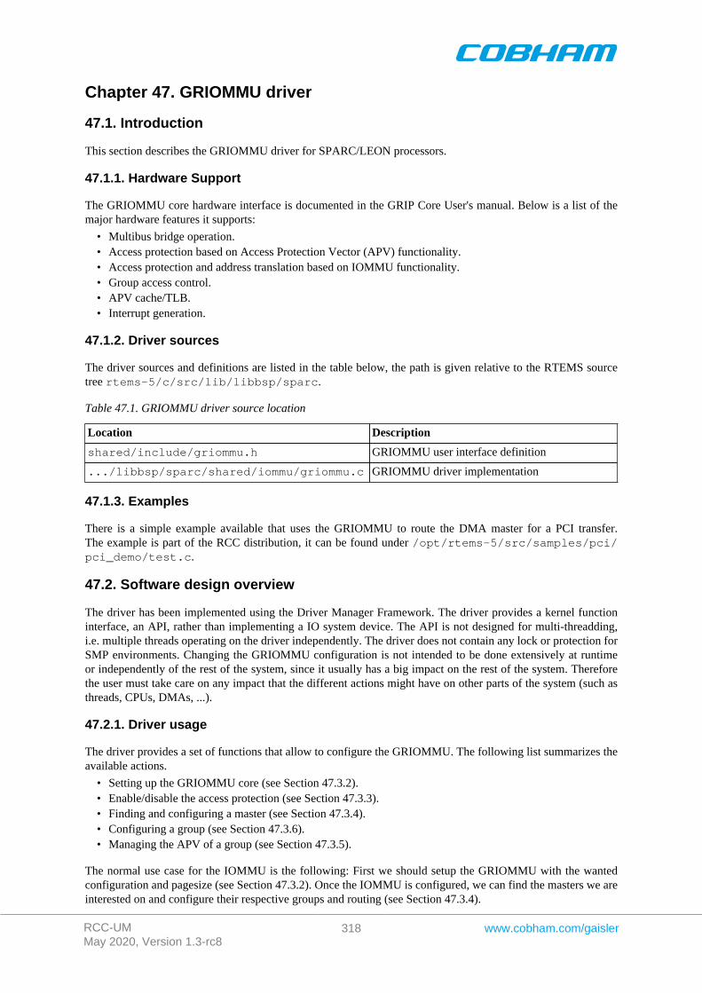
RCC-UMMay 2020, Version 1.3-rc8
318 www.cobham.com/gaisler
Chapter 47. GRIOMMU driver
47.1. Introduction
This section describes the GRIOMMU driver for SPARC/LEON processors.
47.1.1. Hardware Support
The GRIOMMU core hardware interface is documented in the GRIP Core User's manual. Below is a list of themajor hardware features it supports:
• Multibus bridge operation.• Access protection based on Access Protection Vector (APV) functionality.• Access protection and address translation based on IOMMU functionality.• Group access control.• APV cache/TLB.• Interrupt generation.
47.1.2. Driver sources
The driver sources and definitions are listed in the table below, the path is given relative to the RTEMS sourcetree rtems-5/c/src/lib/libbsp/sparc.
Table 47.1. GRIOMMU driver source location
Location Description
shared/include/griommu.h GRIOMMU user interface definition
.../libbsp/sparc/shared/iommu/griommu.c GRIOMMU driver implementation
47.1.3. Examples
There is a simple example available that uses the GRIOMMU to route the DMA master for a PCI transfer.The example is part of the RCC distribution, it can be found under /opt/rtems-5/src/samples/pci/pci_demo/test.c.
47.2. Software design overview
The driver has been implemented using the Driver Manager Framework. The driver provides a kernel functioninterface, an API, rather than implementing a IO system device. The API is not designed for multi-threadding,i.e. multiple threads operating on the driver independently. The driver does not contain any lock or protection forSMP environments. Changing the GRIOMMU configuration is not intended to be done extensively at runtimeor independently of the rest of the system, since it usually has a big impact on the rest of the system. Thereforethe user must take care on any impact that the different actions might have on other parts of the system (such asthreads, CPUs, DMAs, ...).
47.2.1. Driver usage
The driver provides a set of functions that allow to configure the GRIOMMU. The following list summarizes theavailable actions.
• Setting up the GRIOMMU core (see Section 47.3.2).• Enable/disable the access protection (see Section 47.3.3).• Finding and configuring a master (see Section 47.3.4).• Configuring a group (see Section 47.3.6).• Managing the APV of a group (see Section 47.3.5).
The normal use case for the IOMMU is the following: First we should setup the GRIOMMU with the wantedconfiguration and pagesize (see Section 47.3.2). Once the IOMMU is configured, we can find the masters we areinterested on and configure their respective groups and routing (see Section 47.3.4).
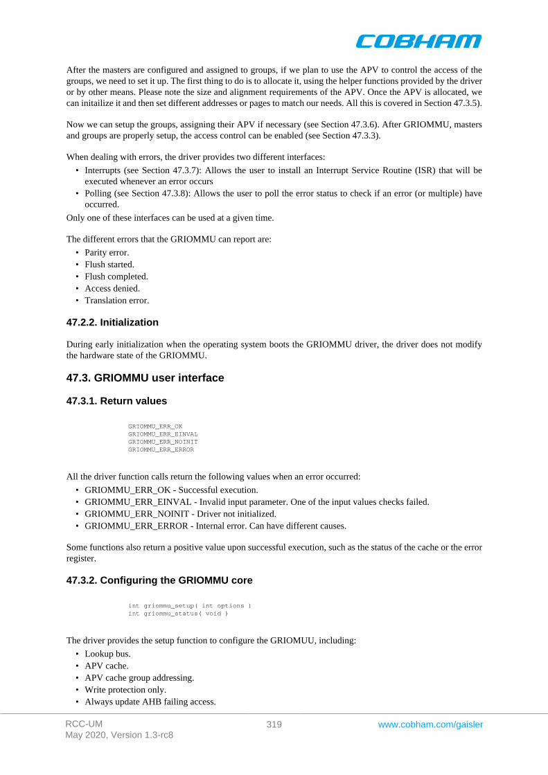
RCC-UMMay 2020, Version 1.3-rc8
319 www.cobham.com/gaisler
After the masters are configured and assigned to groups, if we plan to use the APV to control the access of thegroups, we need to set it up. The first thing to do is to allocate it, using the helper functions provided by the driveror by other means. Please note the size and alignment requirements of the APV. Once the APV is allocated, wecan initailize it and then set different addresses or pages to match our needs. All this is covered in Section 47.3.5).
Now we can setup the groups, assigning their APV if necessary (see Section 47.3.6). After GRIOMMU, mastersand groups are properly setup, the access control can be enabled (see Section 47.3.3).
When dealing with errors, the driver provides two different interfaces:
• Interrupts (see Section 47.3.7): Allows the user to install an Interrupt Service Routine (ISR) that will beexecuted whenever an error occurs
• Polling (see Section 47.3.8): Allows the user to poll the error status to check if an error (or multiple) haveoccurred.
Only one of these interfaces can be used at a given time.
The different errors that the GRIOMMU can report are:
• Parity error.• Flush started.• Flush completed.• Access denied.• Translation error.
47.2.2. Initialization
During early initialization when the operating system boots the GRIOMMU driver, the driver does not modifythe hardware state of the GRIOMMU.
47.3. GRIOMMU user interface
47.3.1. Return values
GRIOMMU_ERR_OK GRIOMMU_ERR_EINVAL GRIOMMU_ERR_NOINIT GRIOMMU_ERR_ERROR
All the driver function calls return the following values when an error occurred:
• GRIOMMU_ERR_OK - Successful execution.• GRIOMMU_ERR_EINVAL - Invalid input parameter. One of the input values checks failed.• GRIOMMU_ERR_NOINIT - Driver not initialized.• GRIOMMU_ERR_ERROR - Internal error. Can have different causes.
Some functions also return a positive value upon successful execution, such as the status of the cache or the errorregister.
47.3.2. Configuring the GRIOMMU core
int griommu_setup( int options ) int griommu_status( void )
The driver provides the setup function to configure the GRIOMUU, including:
• Lookup bus.• APV cache.• APV cache group addressing.• Write protection only.• Always update AHB failing access.
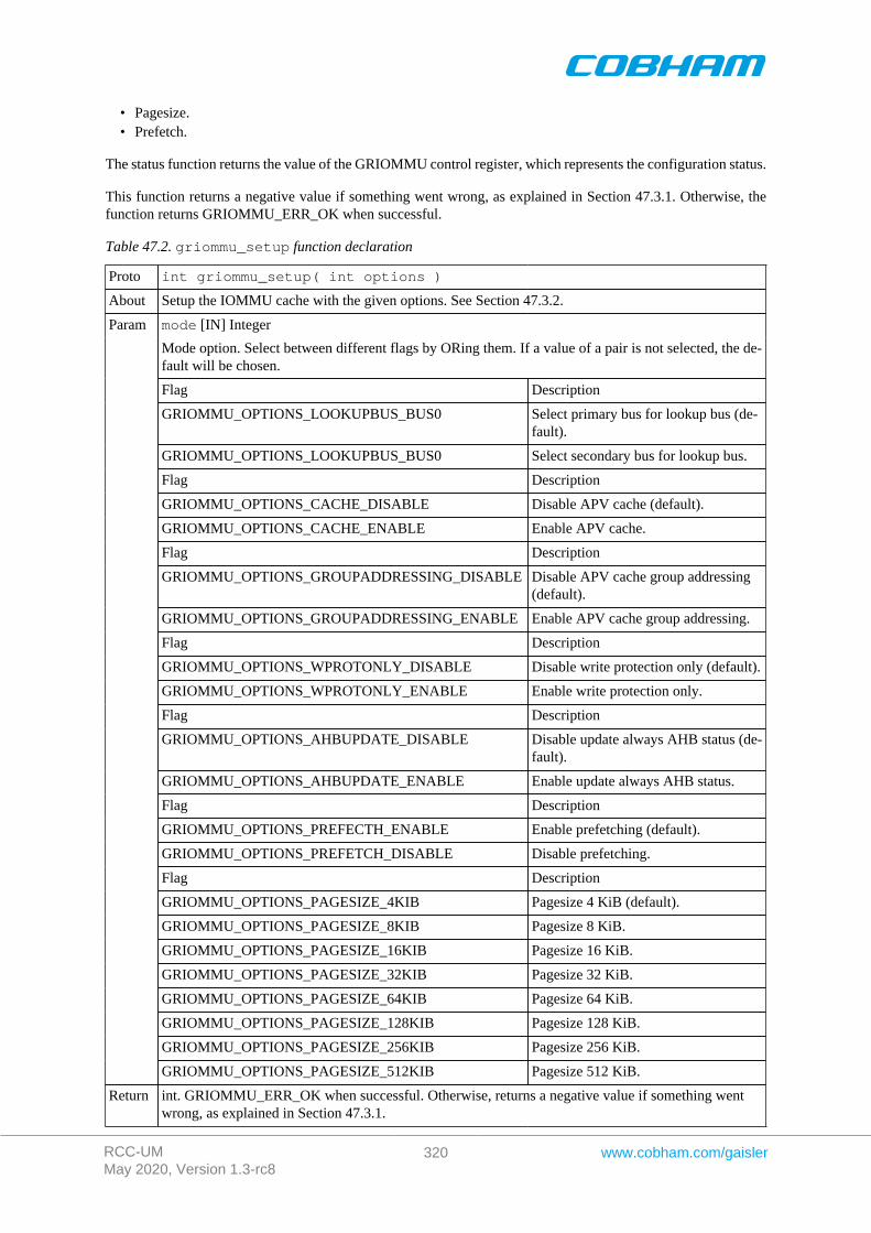
RCC-UMMay 2020, Version 1.3-rc8
320 www.cobham.com/gaisler
• Pagesize.• Prefetch.
The status function returns the value of the GRIOMMU control register, which represents the configuration status.
This function returns a negative value if something went wrong, as explained in Section 47.3.1. Otherwise, thefunction returns GRIOMMU_ERR_OK when successful.
Table 47.2. griommu_setup function declaration
Proto int griommu_setup( int options )
About Setup the IOMMU cache with the given options. See Section 47.3.2.
mode [IN] Integer
Mode option. Select between different flags by ORing them. If a value of a pair is not selected, the de-fault will be chosen.
Flag Description
GRIOMMU_OPTIONS_LOOKUPBUS_BUS0 Select primary bus for lookup bus (de-fault).
GRIOMMU_OPTIONS_LOOKUPBUS_BUS0 Select secondary bus for lookup bus.
Flag Description
GRIOMMU_OPTIONS_CACHE_DISABLE Disable APV cache (default).
GRIOMMU_OPTIONS_CACHE_ENABLE Enable APV cache.
Flag Description
GRIOMMU_OPTIONS_GROUPADDRESSING_DISABLE Disable APV cache group addressing(default).
GRIOMMU_OPTIONS_GROUPADDRESSING_ENABLE Enable APV cache group addressing.
Flag Description
GRIOMMU_OPTIONS_WPROTONLY_DISABLE Disable write protection only (default).
GRIOMMU_OPTIONS_WPROTONLY_ENABLE Enable write protection only.
Flag Description
GRIOMMU_OPTIONS_AHBUPDATE_DISABLE Disable update always AHB status (de-fault).
GRIOMMU_OPTIONS_AHBUPDATE_ENABLE Enable update always AHB status.
Flag Description
GRIOMMU_OPTIONS_PREFECTH_ENABLE Enable prefetching (default).
GRIOMMU_OPTIONS_PREFETCH_DISABLE Disable prefetching.
Flag Description
GRIOMMU_OPTIONS_PAGESIZE_4KIB Pagesize 4 KiB (default).
GRIOMMU_OPTIONS_PAGESIZE_8KIB Pagesize 8 KiB.
GRIOMMU_OPTIONS_PAGESIZE_16KIB Pagesize 16 KiB.
GRIOMMU_OPTIONS_PAGESIZE_32KIB Pagesize 32 KiB.
GRIOMMU_OPTIONS_PAGESIZE_64KIB Pagesize 64 KiB.
GRIOMMU_OPTIONS_PAGESIZE_128KIB Pagesize 128 KiB.
GRIOMMU_OPTIONS_PAGESIZE_256KIB Pagesize 256 KiB.
Param
GRIOMMU_OPTIONS_PAGESIZE_512KIB Pagesize 512 KiB.
Return int. GRIOMMU_ERR_OK when successful. Otherwise, returns a negative value if something wentwrong, as explained in Section 47.3.1.
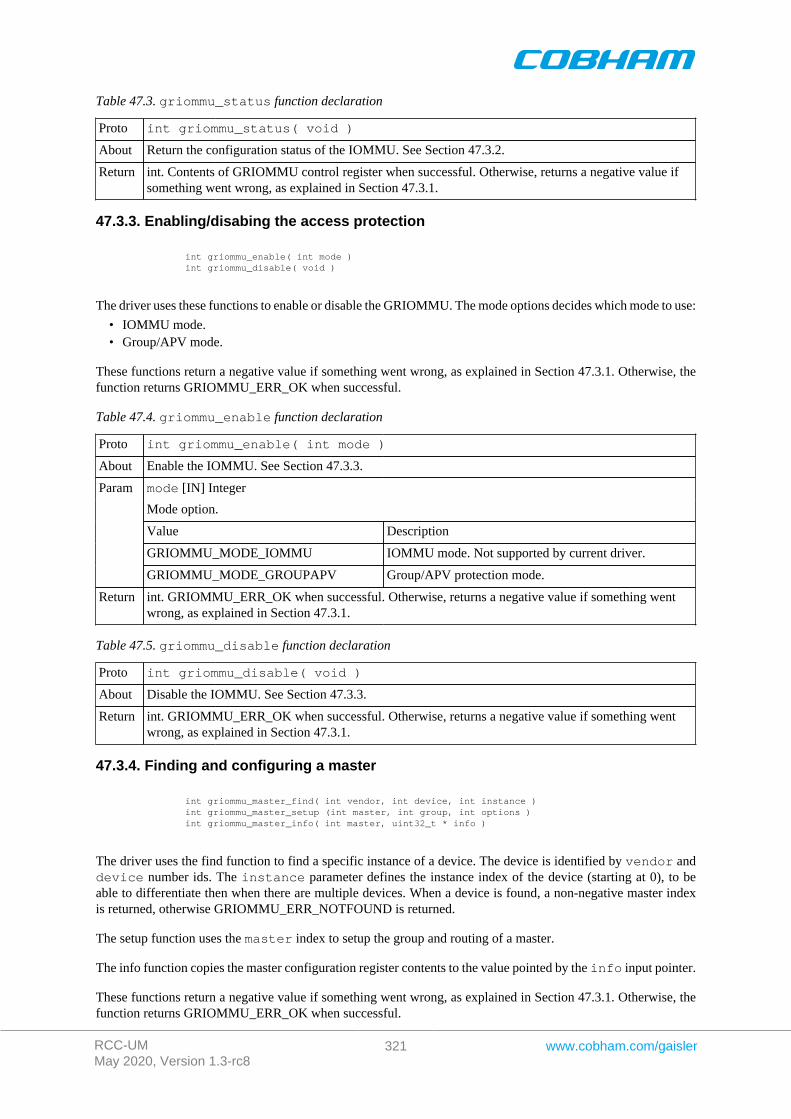
RCC-UMMay 2020, Version 1.3-rc8
321 www.cobham.com/gaisler
Table 47.3. griommu_status function declaration
Proto int griommu_status( void )
About Return the configuration status of the IOMMU. See Section 47.3.2.
Return int. Contents of GRIOMMU control register when successful. Otherwise, returns a negative value ifsomething went wrong, as explained in Section 47.3.1.
47.3.3. Enabling/disabing the access protection
int griommu_enable( int mode ) int griommu_disable( void )
The driver uses these functions to enable or disable the GRIOMMU. The mode options decides which mode to use:
• IOMMU mode.• Group/APV mode.
These functions return a negative value if something went wrong, as explained in Section 47.3.1. Otherwise, thefunction returns GRIOMMU_ERR_OK when successful.
Table 47.4. griommu_enable function declaration
Proto int griommu_enable( int mode )
About Enable the IOMMU. See Section 47.3.3.
mode [IN] Integer
Mode option.
Value Description
GRIOMMU_MODE_IOMMU IOMMU mode. Not supported by current driver.
Param
GRIOMMU_MODE_GROUPAPV Group/APV protection mode.
Return int. GRIOMMU_ERR_OK when successful. Otherwise, returns a negative value if something wentwrong, as explained in Section 47.3.1.
Table 47.5. griommu_disable function declaration
Proto int griommu_disable( void )
About Disable the IOMMU. See Section 47.3.3.
Return int. GRIOMMU_ERR_OK when successful. Otherwise, returns a negative value if something wentwrong, as explained in Section 47.3.1.
47.3.4. Finding and configuring a master
int griommu_master_find( int vendor, int device, int instance ) int griommu_master_setup (int master, int group, int options ) int griommu_master_info( int master, uint32_t * info )
The driver uses the find function to find a specific instance of a device. The device is identified by vendor anddevice number ids. The instance parameter defines the instance index of the device (starting at 0), to beable to differentiate then when there are multiple devices. When a device is found, a non-negative master indexis returned, otherwise GRIOMMU_ERR_NOTFOUND is returned.
The setup function uses the master index to setup the group and routing of a master.
The info function copies the master configuration register contents to the value pointed by the info input pointer.
These functions return a negative value if something went wrong, as explained in Section 47.3.1. Otherwise, thefunction returns GRIOMMU_ERR_OK when successful.
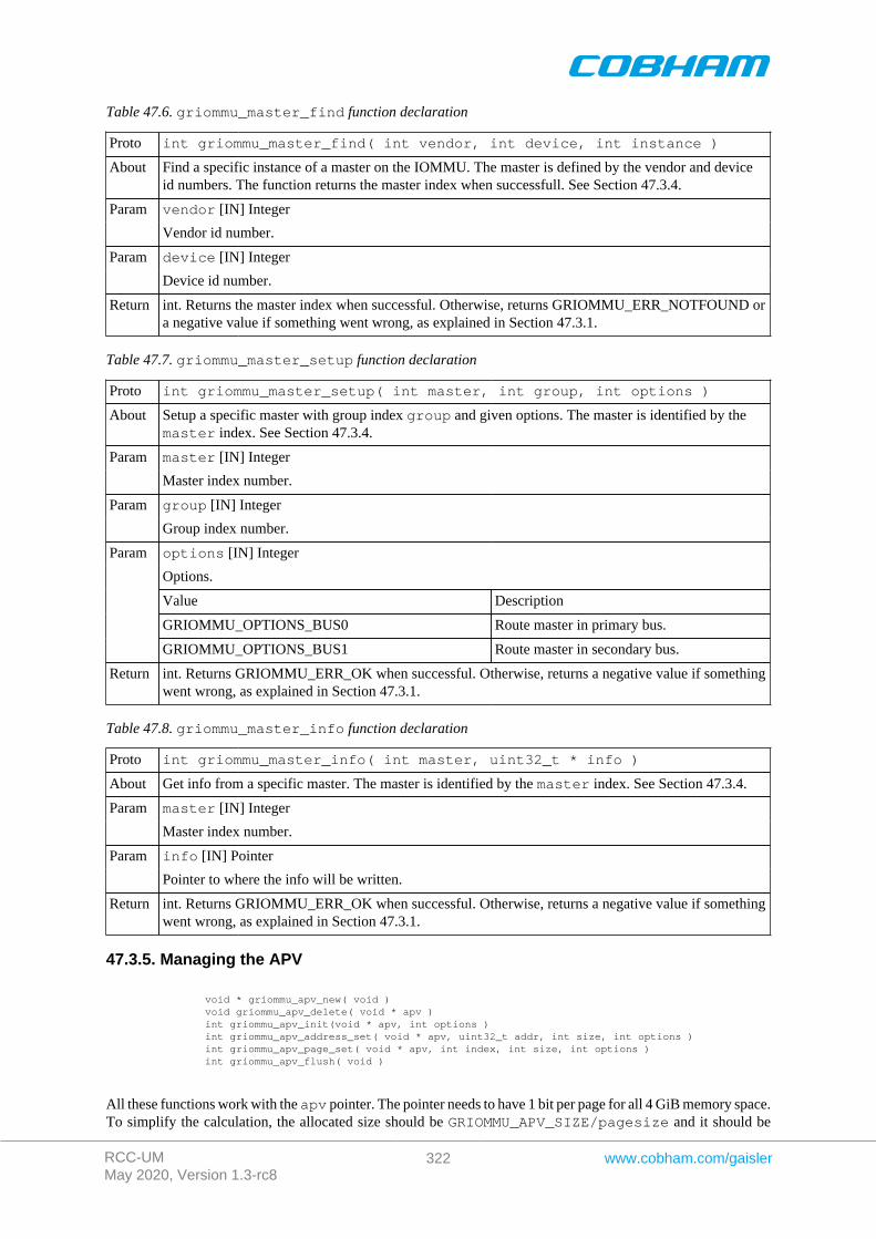
RCC-UMMay 2020, Version 1.3-rc8
322 www.cobham.com/gaisler
Table 47.6. griommu_master_find function declaration
Proto int griommu_master_find( int vendor, int device, int instance )
About Find a specific instance of a master on the IOMMU. The master is defined by the vendor and deviceid numbers. The function returns the master index when successfull. See Section 47.3.4.
vendor [IN] IntegerParam
Vendor id number.
device [IN] IntegerParam
Device id number.
Return int. Returns the master index when successful. Otherwise, returns GRIOMMU_ERR_NOTFOUND ora negative value if something went wrong, as explained in Section 47.3.1.
Table 47.7. griommu_master_setup function declaration
Proto int griommu_master_setup( int master, int group, int options )
About Setup a specific master with group index group and given options. The master is identified by themaster index. See Section 47.3.4.
master [IN] IntegerParam
Master index number.
group [IN] IntegerParam
Group index number.
options [IN] Integer
Options.
Value Description
GRIOMMU_OPTIONS_BUS0 Route master in primary bus.
Param
GRIOMMU_OPTIONS_BUS1 Route master in secondary bus.
Return int. Returns GRIOMMU_ERR_OK when successful. Otherwise, returns a negative value if somethingwent wrong, as explained in Section 47.3.1.
Table 47.8. griommu_master_info function declaration
Proto int griommu_master_info( int master, uint32_t * info )
About Get info from a specific master. The master is identified by the master index. See Section 47.3.4.
master [IN] IntegerParam
Master index number.
info [IN] PointerParam
Pointer to where the info will be written.
Return int. Returns GRIOMMU_ERR_OK when successful. Otherwise, returns a negative value if somethingwent wrong, as explained in Section 47.3.1.
47.3.5. Managing the APV
void * griommu_apv_new( void ) void griommu_apv_delete( void * apv ) int griommu_apv_init(void * apv, int options ) int griommu_apv_address_set( void * apv, uint32_t addr, int size, int options ) int griommu_apv_page_set( void * apv, int index, int size, int options ) int griommu_apv_flush( void )
All these functions work with the apv pointer. The pointer needs to have 1 bit per page for all 4 GiB memory space.To simplify the calculation, the allocated size should be GRIOMMU_APV_SIZE/pagesize and it should be
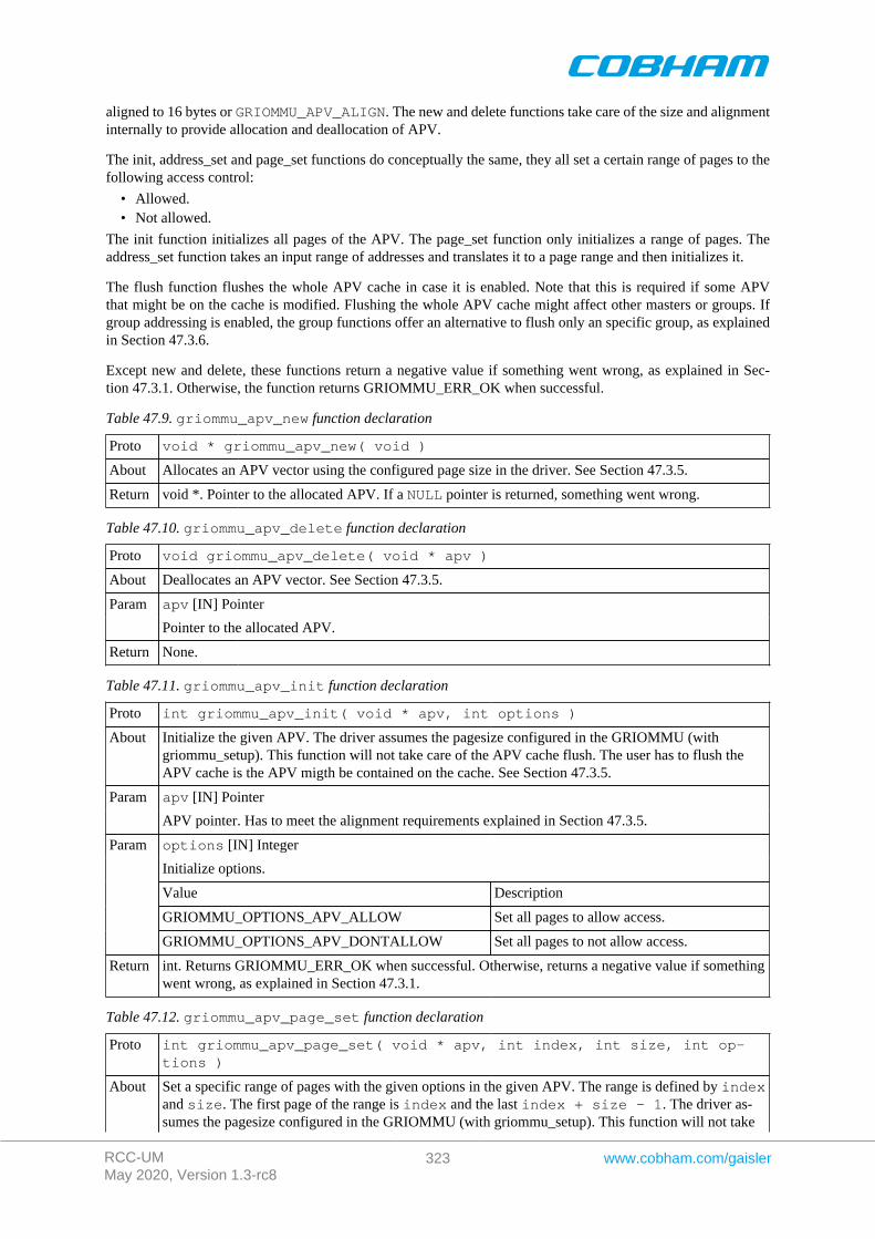
RCC-UMMay 2020, Version 1.3-rc8
323 www.cobham.com/gaisler
aligned to 16 bytes or GRIOMMU_APV_ALIGN. The new and delete functions take care of the size and alignmentinternally to provide allocation and deallocation of APV.
The init, address_set and page_set functions do conceptually the same, they all set a certain range of pages to thefollowing access control:
• Allowed.• Not allowed.
The init function initializes all pages of the APV. The page_set function only initializes a range of pages. Theaddress_set function takes an input range of addresses and translates it to a page range and then initializes it.
The flush function flushes the whole APV cache in case it is enabled. Note that this is required if some APVthat might be on the cache is modified. Flushing the whole APV cache might affect other masters or groups. Ifgroup addressing is enabled, the group functions offer an alternative to flush only an specific group, as explainedin Section 47.3.6.
Except new and delete, these functions return a negative value if something went wrong, as explained in Sec-tion 47.3.1. Otherwise, the function returns GRIOMMU_ERR_OK when successful.
Table 47.9. griommu_apv_new function declaration
Proto void * griommu_apv_new( void )
About Allocates an APV vector using the configured page size in the driver. See Section 47.3.5.
Return void *. Pointer to the allocated APV. If a NULL pointer is returned, something went wrong.
Table 47.10. griommu_apv_delete function declaration
Proto void griommu_apv_delete( void * apv )
About Deallocates an APV vector. See Section 47.3.5.
apv [IN] PointerParam
Pointer to the allocated APV.
Return None.
Table 47.11. griommu_apv_init function declaration
Proto int griommu_apv_init( void * apv, int options )
About Initialize the given APV. The driver assumes the pagesize configured in the GRIOMMU (withgriommu_setup). This function will not take care of the APV cache flush. The user has to flush theAPV cache is the APV migth be contained on the cache. See Section 47.3.5.
apv [IN] PointerParam
APV pointer. Has to meet the alignment requirements explained in Section 47.3.5.
options [IN] Integer
Initialize options.
Value Description
GRIOMMU_OPTIONS_APV_ALLOW Set all pages to allow access.
Param
GRIOMMU_OPTIONS_APV_DONTALLOW Set all pages to not allow access.
Return int. Returns GRIOMMU_ERR_OK when successful. Otherwise, returns a negative value if somethingwent wrong, as explained in Section 47.3.1.
Table 47.12. griommu_apv_page_set function declaration
Proto int griommu_apv_page_set( void * apv, int index, int size, int op-tions )
About Set a specific range of pages with the given options in the given APV. The range is defined by indexand size. The first page of the range is index and the last index + size - 1. The driver as-sumes the pagesize configured in the GRIOMMU (with griommu_setup). This function will not take
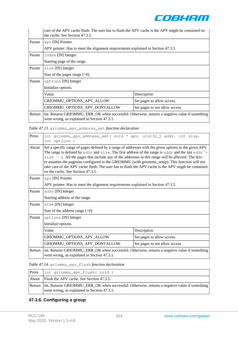
RCC-UMMay 2020, Version 1.3-rc8
324 www.cobham.com/gaisler
care of the APV cache flush. The user has to flush the APV cache is the APV migth be contained onthe cache. See Section 47.3.5.
apv [IN] PointerParam
APV pointer. Has to meet the alignment requirements explained in Section 47.3.5.
index [IN] IntegerParam
Starting page of the range.
size [IN] IntegerParam
Size of the pages range (>0).
options [IN] Integer
Initialize options.
Value Description
GRIOMMU_OPTIONS_APV_ALLOW Set pages to allow access.
Param
GRIOMMU_OPTIONS_APV_DONTALLOW Set pages to not allow access.
Return int. Returns GRIOMMU_ERR_OK when successful. Otherwise, returns a negative value if somethingwent wrong, as explained in Section 47.3.1.
Table 47.13. griommu_apv_address_set function declaration
Proto int griommu_apv_address_set( void * apv, uint32_t addr, int size,int options )
About Set a specific range of pages defined by a range of addresses with the given options in the given APV.The range is defined by addr and size. The first address of the range is addr and the last addr +size - 1. All the pages that include any of the addresses in this range will be affected. The driv-er assumes the pagesize configured in the GRIOMMU (with griommu_setup). This function will nottake care of the APV cache flush. The user has to flush the APV cache is the APV migth be containedon the cache. See Section 47.3.5.
apv [IN] PointerParam
APV pointer. Has to meet the alignment requirements explained in Section 47.3.5.
addr [IN] IntegerParam
Starting address of the range.
size [IN] IntegerParam
Size of the address range (>0).
options [IN] Integer
Initialize options.
Value Description
GRIOMMU_OPTIONS_APV_ALLOW Set pages to allow access.
Param
GRIOMMU_OPTIONS_APV_DONTALLOW Set pages to not allow access.
Return int. Returns GRIOMMU_ERR_OK when successful. Otherwise, returns a negative value if somethingwent wrong, as explained in Section 47.3.1.
Table 47.14. griommu_apv_flush function declaration
Proto int griommu_apv_flush( void )
About Flush the APV cache. See Section 47.3.5.
Return int. Returns GRIOMMU_ERR_OK when successful. Otherwise, returns a negative value if somethingwent wrong, as explained in Section 47.3.1.
47.3.6. Configuring a group
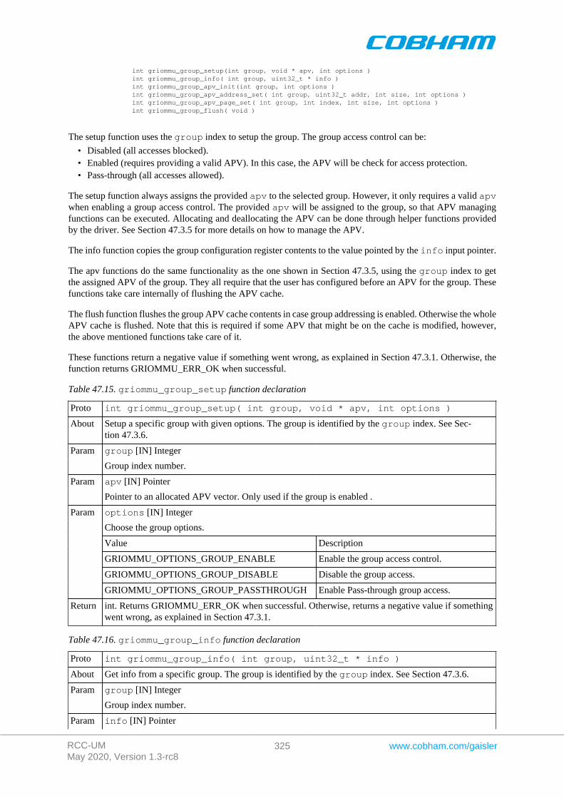
RCC-UMMay 2020, Version 1.3-rc8
325 www.cobham.com/gaisler
int griommu_group_setup(int group, void * apv, int options ) int griommu_group_info( int group, uint32_t * info ) int griommu_group_apv_init(int group, int options ) int griommu_group_apv_address_set( int group, uint32_t addr, int size, int options ) int griommu_group_apv_page_set( int group, int index, int size, int options ) int griommu_group_flush( void )
The setup function uses the group index to setup the group. The group access control can be:
• Disabled (all accesses blocked).• Enabled (requires providing a valid APV). In this case, the APV will be check for access protection.• Pass-through (all accesses allowed).
The setup function always assigns the provided apv to the selected group. However, it only requires a valid apvwhen enabling a group access control. The provided apv will be assigned to the group, so that APV managingfunctions can be executed. Allocating and deallocating the APV can be done through helper functions providedby the driver. See Section 47.3.5 for more details on how to manage the APV.
The info function copies the group configuration register contents to the value pointed by the info input pointer.
The apv functions do the same functionality as the one shown in Section 47.3.5, using the group index to getthe assigned APV of the group. They all require that the user has configured before an APV for the group. Thesefunctions take care internally of flushing the APV cache.
The flush function flushes the group APV cache contents in case group addressing is enabled. Otherwise the wholeAPV cache is flushed. Note that this is required if some APV that might be on the cache is modified, however,the above mentioned functions take care of it.
These functions return a negative value if something went wrong, as explained in Section 47.3.1. Otherwise, thefunction returns GRIOMMU_ERR_OK when successful.
Table 47.15. griommu_group_setup function declaration
Proto int griommu_group_setup( int group, void * apv, int options )
About Setup a specific group with given options. The group is identified by the group index. See Sec-tion 47.3.6.
group [IN] IntegerParam
Group index number.
apv [IN] PointerParam
Pointer to an allocated APV vector. Only used if the group is enabled .
options [IN] Integer
Choose the group options.
Value Description
GRIOMMU_OPTIONS_GROUP_ENABLE Enable the group access control.
GRIOMMU_OPTIONS_GROUP_DISABLE Disable the group access.
Param
GRIOMMU_OPTIONS_GROUP_PASSTHROUGH Enable Pass-through group access.
Return int. Returns GRIOMMU_ERR_OK when successful. Otherwise, returns a negative value if somethingwent wrong, as explained in Section 47.3.1.
Table 47.16. griommu_group_info function declaration
Proto int griommu_group_info( int group, uint32_t * info )
About Get info from a specific group. The group is identified by the group index. See Section 47.3.6.
group [IN] IntegerParam
Group index number.
Param info [IN] Pointer
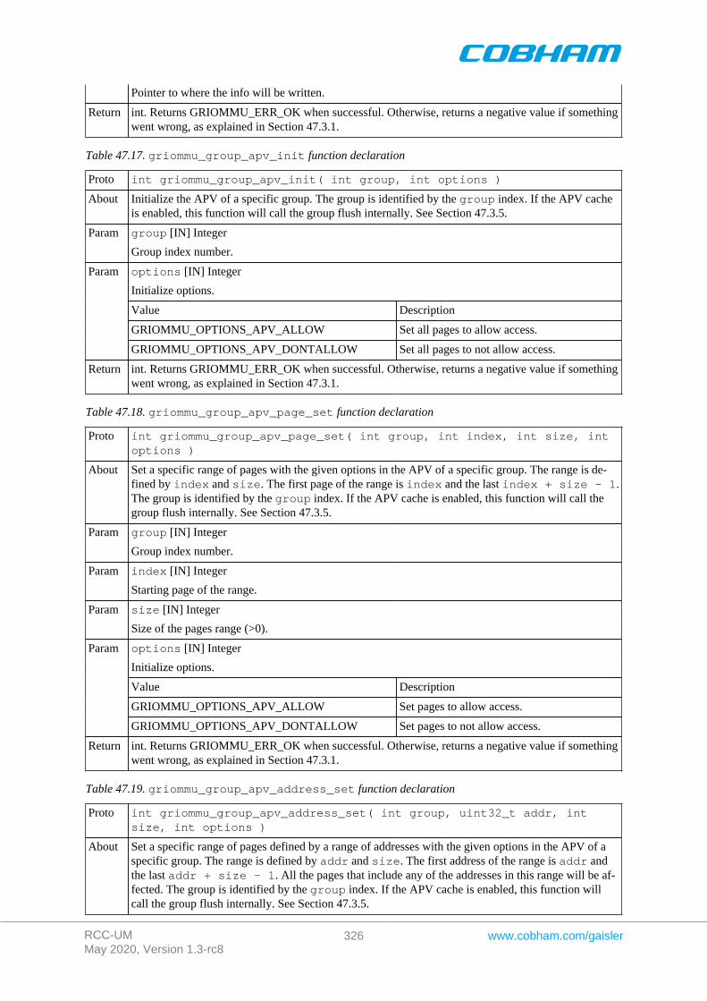
RCC-UMMay 2020, Version 1.3-rc8
326 www.cobham.com/gaisler
Pointer to where the info will be written.
Return int. Returns GRIOMMU_ERR_OK when successful. Otherwise, returns a negative value if somethingwent wrong, as explained in Section 47.3.1.
Table 47.17. griommu_group_apv_init function declaration
Proto int griommu_group_apv_init( int group, int options )
About Initialize the APV of a specific group. The group is identified by the group index. If the APV cacheis enabled, this function will call the group flush internally. See Section 47.3.5.
group [IN] IntegerParam
Group index number.
options [IN] Integer
Initialize options.
Value Description
GRIOMMU_OPTIONS_APV_ALLOW Set all pages to allow access.
Param
GRIOMMU_OPTIONS_APV_DONTALLOW Set all pages to not allow access.
Return int. Returns GRIOMMU_ERR_OK when successful. Otherwise, returns a negative value if somethingwent wrong, as explained in Section 47.3.1.
Table 47.18. griommu_group_apv_page_set function declaration
Proto int griommu_group_apv_page_set( int group, int index, int size, intoptions )
About Set a specific range of pages with the given options in the APV of a specific group. The range is de-fined by index and size. The first page of the range is index and the last index + size - 1.The group is identified by the group index. If the APV cache is enabled, this function will call thegroup flush internally. See Section 47.3.5.
group [IN] IntegerParam
Group index number.
index [IN] IntegerParam
Starting page of the range.
size [IN] IntegerParam
Size of the pages range (>0).
options [IN] Integer
Initialize options.
Value Description
GRIOMMU_OPTIONS_APV_ALLOW Set pages to allow access.
Param
GRIOMMU_OPTIONS_APV_DONTALLOW Set pages to not allow access.
Return int. Returns GRIOMMU_ERR_OK when successful. Otherwise, returns a negative value if somethingwent wrong, as explained in Section 47.3.1.
Table 47.19. griommu_group_apv_address_set function declaration
Proto int griommu_group_apv_address_set( int group, uint32_t addr, intsize, int options )
About Set a specific range of pages defined by a range of addresses with the given options in the APV of aspecific group. The range is defined by addr and size. The first address of the range is addr andthe last addr + size - 1. All the pages that include any of the addresses in this range will be af-fected. The group is identified by the group index. If the APV cache is enabled, this function willcall the group flush internally. See Section 47.3.5.
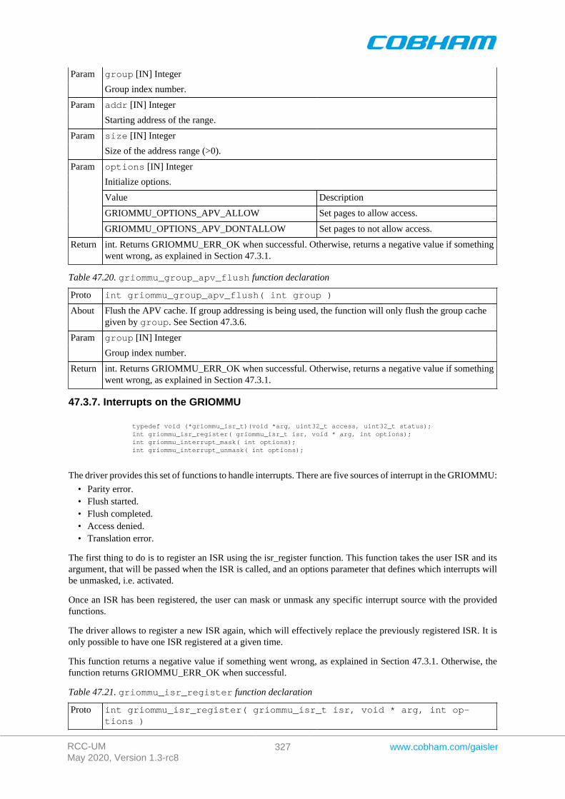
RCC-UMMay 2020, Version 1.3-rc8
327 www.cobham.com/gaisler
group [IN] IntegerParam
Group index number.
addr [IN] IntegerParam
Starting address of the range.
size [IN] IntegerParam
Size of the address range (>0).
options [IN] Integer
Initialize options.
Value Description
GRIOMMU_OPTIONS_APV_ALLOW Set pages to allow access.
Param
GRIOMMU_OPTIONS_APV_DONTALLOW Set pages to not allow access.
Return int. Returns GRIOMMU_ERR_OK when successful. Otherwise, returns a negative value if somethingwent wrong, as explained in Section 47.3.1.
Table 47.20. griommu_group_apv_flush function declaration
Proto int griommu_group_apv_flush( int group )
About Flush the APV cache. If group addressing is being used, the function will only flush the group cachegiven by group. See Section 47.3.6.
group [IN] IntegerParam
Group index number.
Return int. Returns GRIOMMU_ERR_OK when successful. Otherwise, returns a negative value if somethingwent wrong, as explained in Section 47.3.1.
47.3.7. Interrupts on the GRIOMMU
typedef void (*griommu_isr_t)(void *arg, uint32_t access, uint32_t status); int griommu_isr_register( griommu_isr_t isr, void * arg, int options); int griommu_interrupt_mask( int options); int griommu_interrupt_unmask( int options);
The driver provides this set of functions to handle interrupts. There are five sources of interrupt in the GRIOMMU:
• Parity error.• Flush started.• Flush completed.• Access denied.• Translation error.
The first thing to do is to register an ISR using the isr_register function. This function takes the user ISR and itsargument, that will be passed when the ISR is called, and an options parameter that defines which interrupts willbe unmasked, i.e. activated.
Once an ISR has been registered, the user can mask or unmask any specific interrupt source with the providedfunctions.
The driver allows to register a new ISR again, which will effectively replace the previously registered ISR. It isonly possible to have one ISR registered at a given time.
This function returns a negative value if something went wrong, as explained in Section 47.3.1. Otherwise, thefunction returns GRIOMMU_ERR_OK when successful.
Table 47.21. griommu_isr_register function declaration
Proto int griommu_isr_register( griommu_isr_t isr, void * arg, int op-tions )

RCC-UMMay 2020, Version 1.3-rc8
328 www.cobham.com/gaisler
About Registers an ISR for the IOMMU. The options parameter defines which interrupts are going to beunmasked (i.e. enabled). See Section 47.3.7.
isr [IN] PointerParam
The ISR function pointer.
arg [IN] PointerParam
The ISR argument pointer.
options [IN] Integer
Interrupt mask option. Any combinations (by OR operation) of this flags is accepted.
Value Description
GRIOMMU_INTERRUPT_ALL Unmask all interrupts.
GRIOMMU_INTERRUPT_PARITY_ERROR Unmask parity error interrupts.
GRIOMMU_INTERRUPT_FLUSH_COMPLETED Unmask flush completed interrupts.
GRIOMMU_INTERRUPT_FLUSH_STARTED Unmask flush started interrupts.
GRIOMMU_INTERRUPT_ACCESS_DENIED Unmask access denied interrupts.
Param
GRIOMMU_INTERRUPT_TRANSLATION_ERROR Unmask translation error interrupts.
Return int. GRIOMMU_ERR_OK when successful. Otherwise, returns a negative value if something wentwrong, as explained in Section 47.3.1.
Table 47.22. griommu_interrupt_mask function declaration
Proto int griommu_interrupt_mask( int options )
About Mask certain interrupts (i.e. disable), leaving the rest in their current state (only available if an ISR hasbeen register before). The options parameter defines which interrupts are going to be masked. SeeSection 47.3.7.
options [IN] Integer
Interrupt mask option. Any combinations (by OR operation) of this flags is accepted.
Value Description
GRIOMMU_INTERRUPT_ALL Mask all interrupts.
GRIOMMU_INTERRUPT_PARITY_ERROR Mask parity error interrupts.
GRIOMMU_INTERRUPT_FLUSH_COMPLETED Mask flush completed interrupts.
GRIOMMU_INTERRUPT_FLUSH_STARTED Mask flush started interrupts.
GRIOMMU_INTERRUPT_ACCESS_DENIED Mask access denied interrupts.
Param
GRIOMMU_INTERRUPT_TRANSLATION_ERROR Mask translation error interrupts.
Return int. GRIOMMU_ERR_OK when successful. Otherwise, returns a negative value if something wentwrong, as explained in Section 46.3.1.
Table 47.23. griommu_interrupt_unmask function declaration
Proto int griommu_interrupt_unmask( int options )
About Unmask certain interrupts (i.e. enable), leaving the rest in their current state (only available if anISR has been register before). The options parameter defines which interrupts are going to be un-masked. See Section 47.3.7.
options [IN] Integer
Interrupt mask option. Any combinations (by OR operation) of this flags is accepted.
Value Description
GRIOMMU_INTERRUPT_ALL Unmask all interrupts.
Param
GRIOMMU_INTERRUPT_PARITY_ERROR Unmask parity error interrupts.

RCC-UMMay 2020, Version 1.3-rc8
329 www.cobham.com/gaisler
GRIOMMU_INTERRUPT_FLUSH_COMPLETED Unmask flush completed interrupts.
GRIOMMU_INTERRUPT_FLUSH_STARTED Unmask flush started interrupts.
GRIOMMU_INTERRUPT_ACCESS_DENIED Unmask access denied interrupts.
GRIOMMU_INTERRUPT_TRANSLATION_ERROR Unmask translation error interrupts.
Return int. GRIOMMU_ERR_OK when successful. Otherwise, returns a negative value if something wentwrong, as explained in Section 47.3.1.
47.3.8. Polling the error status of the GRIOMMU
int griommu_error_status( uint32_t * access );
The driver provides this function to handle errors as an alternative to interrupts. There are five sources of interruptin the GRIOMMU:
• Parity error.• Flush started.• Flush completed.• Access denied.• Translation error.
This function will return the status register contents if a error has occurred. If it is the case, then it will copy theAHB failing access register to the value pointed by access ( if a valid pointer is given).
If an error has been detected, this function will internally reset the error status register to be able to catch new errors.
Please note that this function should not be used when interrupts are being used.
This function returns a negative value if something went wrong, as explained in Section 47.3.1. Otherwise, thefunction returns the error status when successful.
Table 47.24. griommu_error_status function declaration
Proto int l2cache_error_status( uint32_t * access )
About Poll the state of the error status register. Returns the status register value if an error have been detect-ed. Also this function clears the hardware error flags if an error has been detected. Optionally can pro-vide the AHB failing access register content. See Section 47.3.8.
access [OUT] PointerParam
If a non NULL pointer is given, and in the case of an errors, the value pointed will be updated with theAHB failing access register.
Return int. A positive value indicating the status register value when succesful. Otherwise, returns a negativevalue if something went wrong, as explained in Section 47.3.1.
47.4. API reference
This section lists all functions part of the GRIOMMU driver API, and in which section(s) they are described. TheAPI is also documented in the source header file of the driver, see Section 47.1.2.
Table 47.25. GRIOMMU function reference
Prototype Section
int griommu_setup( int options ) 47.3.2
int griommu_status( void ) 47.3.2
int griommu_enable( int mode ) 47.3.3
int griommu_disable( void ) 47.3.3
int griommu_master_find( int vendor, int device, int instance ) 47.3.4
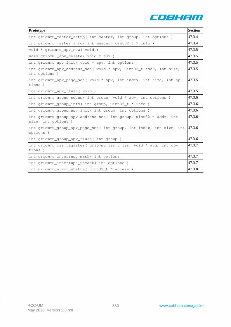
RCC-UMMay 2020, Version 1.3-rc8
330 www.cobham.com/gaisler
Prototype Section
int griommu_master_setup( int master, int group, int options ) 47.3.4
int griommu_master_info( int master, uint32_t * info ) 47.3.4
void * griommu_apv_new( void ) 47.3.5
void griommu_apv_delete( void * apv ) 47.3.5
int griommu_apv_init( void * apv, int options ) 47.3.5
int griommu_apv_address_set( void * apv, uint32_t addr, int size,int options )
47.3.5
int griommu_apv_page_set( void * apv, int index, int size, int op-tions )
47.3.5
int griommu_apv_flush( void ) 47.3.5
int griommu_group_setup( int group, void * apv, int options ) 47.3.6
int griommu_group_info( int group, uint32_t * info ) 47.3.6
int griommu_group_apv_init( int group, int options ) 47.3.6
int griommu_group_apv_address_set( int group, uint32_t addr, intsize, int options )
47.3.6
int griommu_group_apv_page_set( int group, int index, int size, intoptions )
47.3.6
int griommu_group_apv_flush( int group ) 47.3.6
int griommu_isr_register( griommu_isr_t isr, void * arg, int op-tions )
47.3.7
int griommu_interrupt_mask( int options ) 47.3.7
int griommu_interrupt_unmask( int options ) 47.3.7
int griommu_error_status( uint32_t * access ) 47.3.8

RCC-UMMay 2020, Version 1.3-rc8
331 www.cobham.com/gaisler
Chapter 48. L4STAT/L3STAT driver
48.1. Introduction
This section describes the L4STAT driver for SPARC/LEON processors. This driver is also compatible with theL3STAT core. Everything explained in the next sections is also applicable to the L3STAT core.
48.1.1. Hardware Support
The L4STAT core hardware interface is documented in the GRIP Core User's manual. The L4STAT core is usedto count events in the LEON4 processor and the AHB bus in order to create performance statistics.
48.1.2. Driver sources
The driver sources and definitions are listed in the table below, the path is given relative to the RTEMS sourcetree rtems-5/c/src/lib/libbsp/sparc.
Table 48.1. L4STAT driver source location
Location Description
shared/include/l4stat.h L4STAT user interface definition
.../libbsp/sparc/shared/stat/l4stat.c L4STAT driver implementation
48.1.3. Examples
There is a simple example available that uses the L4STAT driver to poll the execution time counter every second.The example is part of the RCC distribution, it can be found under /opt/rtems-5/src/samples/l4stat/test.c.
48.2. Software design overview
The driver has been implemented using the Driver Manager Framework. The driver provides a kernel functioninterface, an API, rather than implementing a IO system device. The API is SMP safe. The driver does not containany locking mechanism on SMP environments.
48.2.1. Driver usage
The driver provides a set of functions that allow to configure and operate each of the available L4STAT countersindependently. The following list summarizes the available actions.
• Enable/disable a counter (see Section 48.3.2).• Get/set/clear a counter (see Section 48.3.3).• Get/set max counter value (see Section 48.3.4).• Get/set timestamp (see Section 48.3.5).
48.2.2. Initialization
During early initialization when the operating system boots the L4STAT driver, the driver does not modify thehardware state of the L4STAT.
48.3. L4STAT user interface
48.3.1. Return values
L4STAT_ERR_OK L4STAT_ERR_EINVAL L4STAT_ERR_TOOMANY L4STAT_ERR_ERROR
All the driver function calls return the following values when an error occurred:
• L4STAT_ERR_OK - Successful execution.
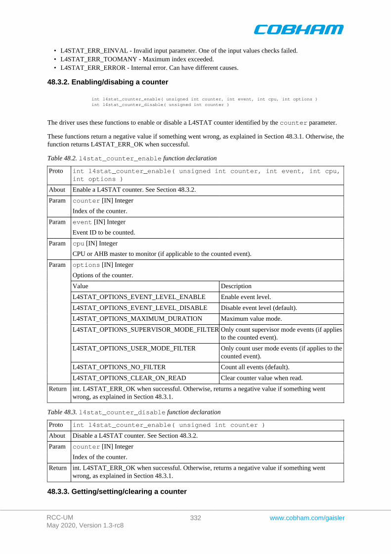
RCC-UMMay 2020, Version 1.3-rc8
332 www.cobham.com/gaisler
• L4STAT_ERR_EINVAL - Invalid input parameter. One of the input values checks failed.• L4STAT_ERR_TOOMANY - Maximum index exceeded.• L4STAT_ERR_ERROR - Internal error. Can have different causes.
48.3.2. Enabling/disabing a counter
int l4stat_counter_enable( unsigned int counter, int event, int cpu, int options ) int l4stat_counter_disable( unsigned int counter )
The driver uses these functions to enable or disable a L4STAT counter identified by the counter parameter.
These functions return a negative value if something went wrong, as explained in Section 48.3.1. Otherwise, thefunction returns L4STAT_ERR_OK when successful.
Table 48.2. l4stat_counter_enable function declaration
Proto int l4stat_counter_enable( unsigned int counter, int event, int cpu,int options )
About Enable a L4STAT counter. See Section 48.3.2.
counter [IN] IntegerParam
Index of the counter.
event [IN] IntegerParam
Event ID to be counted.
cpu [IN] IntegerParam
CPU or AHB master to monitor (if applicable to the counted event).
options [IN] Integer
Options of the counter.
Value Description
L4STAT_OPTIONS_EVENT_LEVEL_ENABLE Enable event level.
L4STAT_OPTIONS_EVENT_LEVEL_DISABLE Disable event level (default).
L4STAT_OPTIONS_MAXIMUM_DURATION Maximum value mode.
L4STAT_OPTIONS_SUPERVISOR_MODE_FILTER Only count supervisor mode events (if appliesto the counted event).
L4STAT_OPTIONS_USER_MODE_FILTER Only count user mode events (if applies to thecounted event).
L4STAT_OPTIONS_NO_FILTER Count all events (default).
Param
L4STAT_OPTIONS_CLEAR_ON_READ Clear counter value when read.
Return int. L4STAT_ERR_OK when successful. Otherwise, returns a negative value if something wentwrong, as explained in Section 48.3.1.
Table 48.3. l4stat_counter_disable function declaration
Proto int l4stat_counter_enable( unsigned int counter )
About Disable a L4STAT counter. See Section 48.3.2.
counter [IN] IntegerParam
Index of the counter.
Return int. L4STAT_ERR_OK when successful. Otherwise, returns a negative value if something wentwrong, as explained in Section 48.3.1.
48.3.3. Getting/setting/clearing a counter
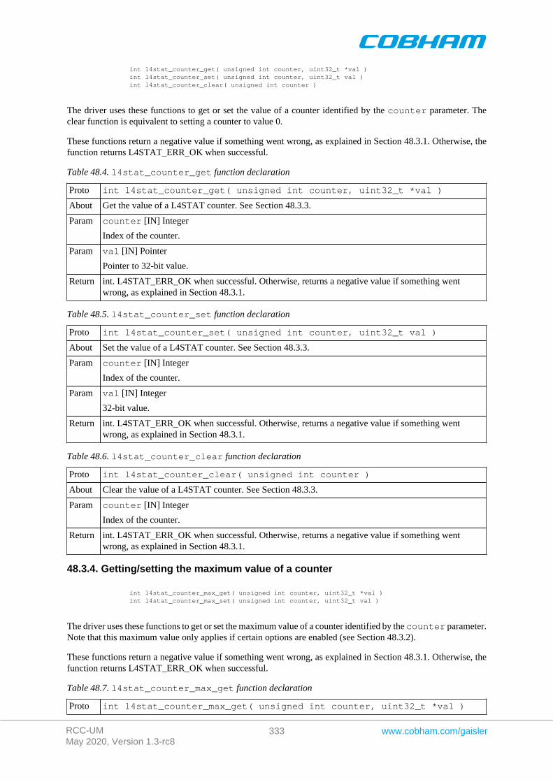
RCC-UMMay 2020, Version 1.3-rc8
333 www.cobham.com/gaisler
int l4stat_counter_get( unsigned int counter, uint32_t *val ) int l4stat_counter_set( unsigned int counter, uint32_t val ) int l4stat_counter_clear( unsigned int counter )
The driver uses these functions to get or set the value of a counter identified by the counter parameter. Theclear function is equivalent to setting a counter to value 0.
These functions return a negative value if something went wrong, as explained in Section 48.3.1. Otherwise, thefunction returns L4STAT_ERR_OK when successful.
Table 48.4. l4stat_counter_get function declaration
Proto int l4stat_counter_get( unsigned int counter, uint32_t *val )
About Get the value of a L4STAT counter. See Section 48.3.3.
counter [IN] IntegerParam
Index of the counter.
val [IN] PointerParam
Pointer to 32-bit value.
Return int. L4STAT_ERR_OK when successful. Otherwise, returns a negative value if something wentwrong, as explained in Section 48.3.1.
Table 48.5. l4stat_counter_set function declaration
Proto int l4stat_counter_set( unsigned int counter, uint32_t val )
About Set the value of a L4STAT counter. See Section 48.3.3.
counter [IN] IntegerParam
Index of the counter.
val [IN] IntegerParam
32-bit value.
Return int. L4STAT_ERR_OK when successful. Otherwise, returns a negative value if something wentwrong, as explained in Section 48.3.1.
Table 48.6. l4stat_counter_clear function declaration
Proto int l4stat_counter_clear( unsigned int counter )
About Clear the value of a L4STAT counter. See Section 48.3.3.
counter [IN] IntegerParam
Index of the counter.
Return int. L4STAT_ERR_OK when successful. Otherwise, returns a negative value if something wentwrong, as explained in Section 48.3.1.
48.3.4. Getting/setting the maximum value of a counter
int l4stat_counter_max_get( unsigned int counter, uint32_t *val ) int l4stat_counter_max_set( unsigned int counter, uint32_t val )
The driver uses these functions to get or set the maximum value of a counter identified by the counter parameter.Note that this maximum value only applies if certain options are enabled (see Section 48.3.2).
These functions return a negative value if something went wrong, as explained in Section 48.3.1. Otherwise, thefunction returns L4STAT_ERR_OK when successful.
Table 48.7. l4stat_counter_max_get function declaration
Proto int l4stat_counter_max_get( unsigned int counter, uint32_t *val )
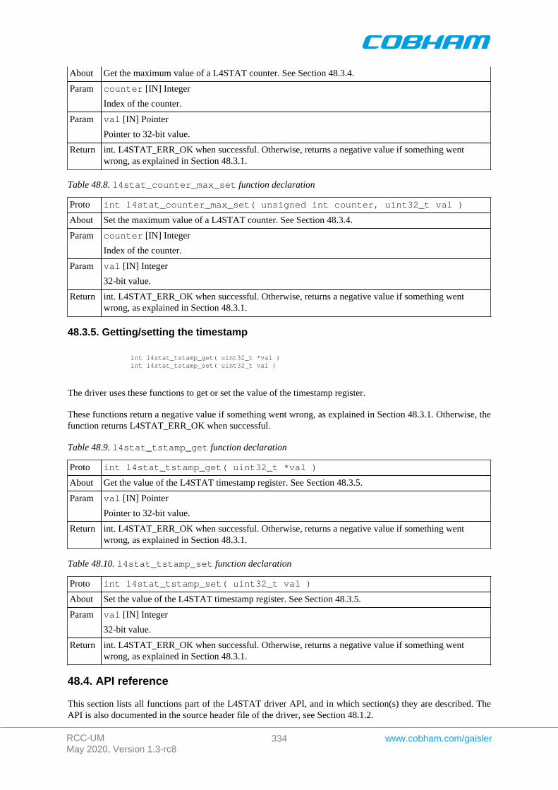
RCC-UMMay 2020, Version 1.3-rc8
334 www.cobham.com/gaisler
About Get the maximum value of a L4STAT counter. See Section 48.3.4.
counter [IN] IntegerParam
Index of the counter.
val [IN] PointerParam
Pointer to 32-bit value.
Return int. L4STAT_ERR_OK when successful. Otherwise, returns a negative value if something wentwrong, as explained in Section 48.3.1.
Table 48.8. l4stat_counter_max_set function declaration
Proto int l4stat_counter_max_set( unsigned int counter, uint32_t val )
About Set the maximum value of a L4STAT counter. See Section 48.3.4.
counter [IN] IntegerParam
Index of the counter.
val [IN] IntegerParam
32-bit value.
Return int. L4STAT_ERR_OK when successful. Otherwise, returns a negative value if something wentwrong, as explained in Section 48.3.1.
48.3.5. Getting/setting the timestamp
int l4stat_tstamp_get( uint32_t *val ) int l4stat_tstamp_set( uint32_t val )
The driver uses these functions to get or set the value of the timestamp register.
These functions return a negative value if something went wrong, as explained in Section 48.3.1. Otherwise, thefunction returns L4STAT_ERR_OK when successful.
Table 48.9. l4stat_tstamp_get function declaration
Proto int l4stat_tstamp_get( uint32_t *val )
About Get the value of the L4STAT timestamp register. See Section 48.3.5.
val [IN] PointerParam
Pointer to 32-bit value.
Return int. L4STAT_ERR_OK when successful. Otherwise, returns a negative value if something wentwrong, as explained in Section 48.3.1.
Table 48.10. l4stat_tstamp_set function declaration
Proto int l4stat_tstamp_set( uint32_t val )
About Set the value of the L4STAT timestamp register. See Section 48.3.5.
val [IN] IntegerParam
32-bit value.
Return int. L4STAT_ERR_OK when successful. Otherwise, returns a negative value if something wentwrong, as explained in Section 48.3.1.
48.4. API reference
This section lists all functions part of the L4STAT driver API, and in which section(s) they are described. TheAPI is also documented in the source header file of the driver, see Section 48.1.2.
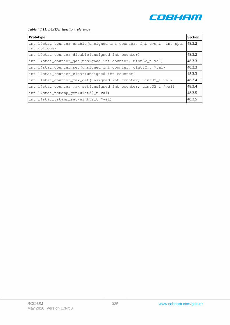
RCC-UMMay 2020, Version 1.3-rc8
335 www.cobham.com/gaisler
Table 48.11. L4STAT function reference
Prototype Section
int l4stat_counter_enable(unsigned int counter, int event, int cpu,int options)
48.3.2
int l4stat_counter_disable(unsigned int counter) 48.3.2
int l4stat_counter_get(unsigned int counter, uint32_t val) 48.3.3
int l4stat_counter_set(unsigned int counter, uint32_t *val) 48.3.3
int l4stat_counter_clear(unsigned int counter) 48.3.3
int l4stat_counter_max_get(unsigned int counter, uint32_t val) 48.3.4
int l4stat_counter_max_set(unsigned int counter, uint32_t *val) 48.3.4
int l4stat_tstamp_get(uint32_t val) 48.3.5
int l4stat_tstamp_set(uint32_t *val) 48.3.5

RCC-UMMay 2020, Version 1.3-rc8
336 www.cobham.com/gaisler
Chapter 49. Memory Scrubber driver
49.1. Introduction
This section describes the Memory Scrubber (MEMSCRUB) driver for SPARC/LEON processors.
49.1.1. Hardware Support
The MEMSCRUB core hardware interface is documented in the GRIP Core User's manual. The MEMSCRUBcore is used to monitor the memory AHB bus and can be programmed to scrub a memory area.
49.1.2. Driver sources
The driver sources and definitions are listed in the table below, the path is given relative to the RTEMS sourcetree rtems-5/c/src/lib/libbsp/sparc.
Table 49.1. MEMSCRUB driver source location
Location Description
shared/include/memscrub.h MEMSCRUB user interface definition
.../libbsp/sparc/shared/scrub/memscrub.c
MEMSCRUB driver implementation
49.1.3. Examples
There is a simple example available that uses the MEMSCRUB driver to scrub a memory area and log the dif-ferent events. The example is part of the RCC distribution, it can be found under /opt/rtems-5/src/sam-ples/memscrub/test.c.
49.2. Software design overview
The driver has been implemented using the Driver Manager Framework. The driver provides a kernel functioninterface, an API, rather than implementing a IO system device.
The API is not designed for multi-threadding, i.e. multiple threads operating on the driver independently. Thedriver does not contain any lock or protection for SMP environments. Changing the MEMSCRUB configurationis not intended to be done extensively at runtime or independently of the rest of the system, since it usually hasa system-level impact. Therefore the user must take care of any impact that the different actions might have onother parts of the system (such as threads, CPUs, DMAs, ...).
49.2.1. Driver usage
The driver provides a set of functions that allow to start and stop the scrubber in different modes. The first step isto setup the memory range (or memory ranges) in which the scrubber is going to act (see Section 49.3.2).
After setting up the range we can start the scrubber in one of the three modes available (see Section 49.3.3):
• Init mode: Initialize the memory area.• Scrub mode: Scrub the memory area.• Regen mode: Regenerate the memory area. Similar to scrub mode, but has an optimized access pattern for
correcting many errors.
Note that scrub and regen mode can be changed on the fly.
The driver provides functions to check if the scrubber is active and to stop it (see Section 49.3.3).
When dealing with errors, the drivers provides two different interfaces:
• Interrupts (see Section 49.3.5): Allows the user to install an Interrupt Service Routine (ISR) that will be exe-cuted whenever an error exceeds its corresponding threshold. Also the MEMSCRUB core allows to generatean interrupt when its done.
• Polling (see Section 49.3.6): Allows the user to poll the error status to check if an error have occurred.
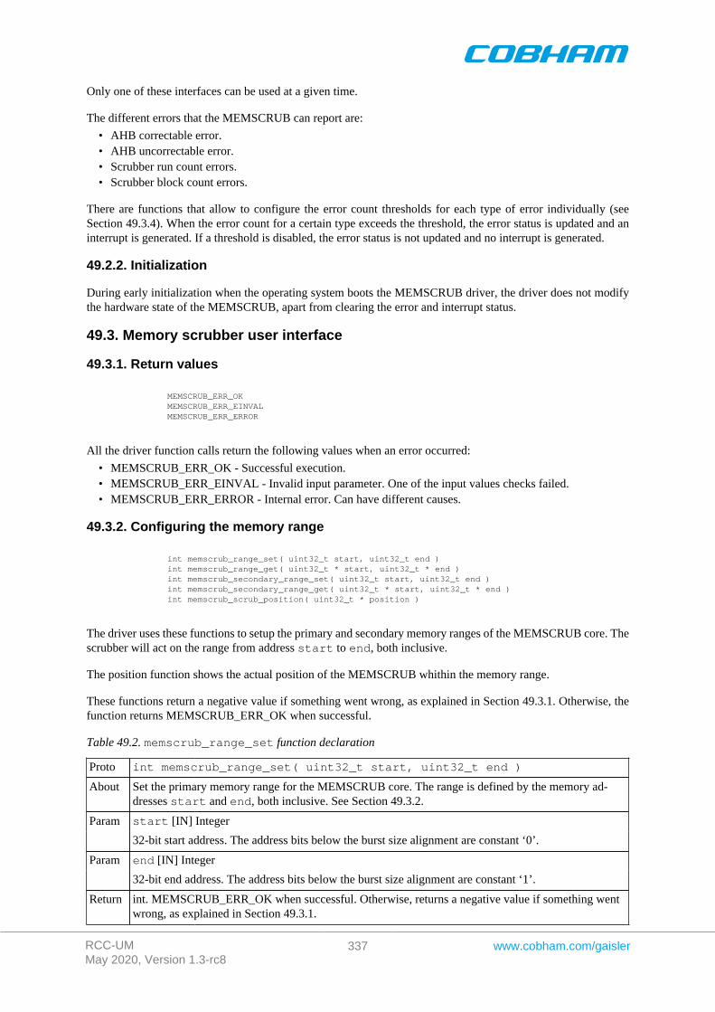
RCC-UMMay 2020, Version 1.3-rc8
337 www.cobham.com/gaisler
Only one of these interfaces can be used at a given time.
The different errors that the MEMSCRUB can report are:
• AHB correctable error.• AHB uncorrectable error.• Scrubber run count errors.• Scrubber block count errors.
There are functions that allow to configure the error count thresholds for each type of error individually (seeSection 49.3.4). When the error count for a certain type exceeds the threshold, the error status is updated and aninterrupt is generated. If a threshold is disabled, the error status is not updated and no interrupt is generated.
49.2.2. Initialization
During early initialization when the operating system boots the MEMSCRUB driver, the driver does not modifythe hardware state of the MEMSCRUB, apart from clearing the error and interrupt status.
49.3. Memory scrubber user interface
49.3.1. Return values
MEMSCRUB_ERR_OK MEMSCRUB_ERR_EINVAL MEMSCRUB_ERR_ERROR
All the driver function calls return the following values when an error occurred:
• MEMSCRUB_ERR_OK - Successful execution.• MEMSCRUB_ERR_EINVAL - Invalid input parameter. One of the input values checks failed.• MEMSCRUB_ERR_ERROR - Internal error. Can have different causes.
49.3.2. Configuring the memory range
int memscrub_range_set( uint32_t start, uint32_t end ) int memscrub_range_get( uint32_t * start, uint32_t * end ) int memscrub_secondary_range_set( uint32_t start, uint32_t end ) int memscrub_secondary_range_get( uint32_t * start, uint32_t * end ) int memscrub_scrub_position( uint32_t * position )
The driver uses these functions to setup the primary and secondary memory ranges of the MEMSCRUB core. Thescrubber will act on the range from address start to end, both inclusive.
The position function shows the actual position of the MEMSCRUB whithin the memory range.
These functions return a negative value if something went wrong, as explained in Section 49.3.1. Otherwise, thefunction returns MEMSCRUB_ERR_OK when successful.
Table 49.2. memscrub_range_set function declaration
Proto int memscrub_range_set( uint32_t start, uint32_t end )
About Set the primary memory range for the MEMSCRUB core. The range is defined by the memory ad-dresses start and end, both inclusive. See Section 49.3.2.
start [IN] IntegerParam
32-bit start address. The address bits below the burst size alignment are constant ‘0’.
end [IN] IntegerParam
32-bit end address. The address bits below the burst size alignment are constant ‘1’.
Return int. MEMSCRUB_ERR_OK when successful. Otherwise, returns a negative value if something wentwrong, as explained in Section 49.3.1.

RCC-UMMay 2020, Version 1.3-rc8
338 www.cobham.com/gaisler
Table 49.3. memscrub_range_get function declaration
Proto int memscrub_range_get( uint32_t * start, uint32_t * end )
About Get the primary memory range for the MEMSCRUB core. The range is defined by the memory ad-dresses start and end, both inclusive. See Section 49.3.2.
start [IN] PointerParam
Pointer to the 32-bit start address. The address bits below the burst size alignment are constant ‘0’.
end [IN] PointerParam
Pointer to the 32-bit end address. The address bits below the burst size alignment are constant ‘1’.
Return int. MEMSCRUB_ERR_OK when successful. Otherwise, returns a negative value if something wentwrong, as explained in Section 49.3.1.
Table 49.4. memscrub_secondary_range_set function declaration
Proto int memscrub_secondary_range_set( uint32_t start, uint32_t end )
About Set the primary memory range for the MEMSCRUB core. The range is defined by the memory ad-dresses start and end, both inclusive. See Section 49.3.2.
start [IN] IntegerParam
32-bit start address. The address bits below the burst size alignment are constant ‘0’.
end [IN] IntegerParam
32-bit end address. The address bits below the burst size alignment are constant ‘1’.
Return int. MEMSCRUB_ERR_OK when successful. Otherwise, returns a negative value if something wentwrong, as explained in Section 49.3.1.
Table 49.5. memscrub_secondary_range_get function declaration
Proto int memscrub_secondary_range_get( uint32_t * start, uint32_t * end )
About Get the secondary memory range for the MEMSCRUB core. The range is defined by the memory ad-dresses start and end, both inclusive. See Section 49.3.2.
start [IN] PointerParam
Pointer to the 32-bit start address. The address bits below the burst size alignment are constant ‘0’.
end [IN] PointerParam
Pointer to the 32-bit end address. The address bits below the burst size alignment are constant ‘1’.
Return int. MEMSCRUB_ERR_OK when successful. Otherwise, returns a negative value if something wentwrong, as explained in Section 49.3.1.
Table 49.6. memscrub_scrub_position function declaration
Proto int memscrub_scrub_position( uint32_t * position )
About Get the position of the scrubber within the memory range. See Section 49.3.2.
position [IN] PointerParam
Pointer to the 32-bit position address.
Return int. MEMSCRUB_ERR_OK when successful. Otherwise, returns a negative value if something wentwrong, as explained in Section 49.3.1.
49.3.3. Starting/stoping different modes.
int memscrub_init_start( uint32_t value, uint8_t delay, int options ) int memscrub_scrub_start( uint8_t delay, int options ) int memscrub_regen_start( uint8_t delay, int options ) int memscrub_stop() int memscrub_active()
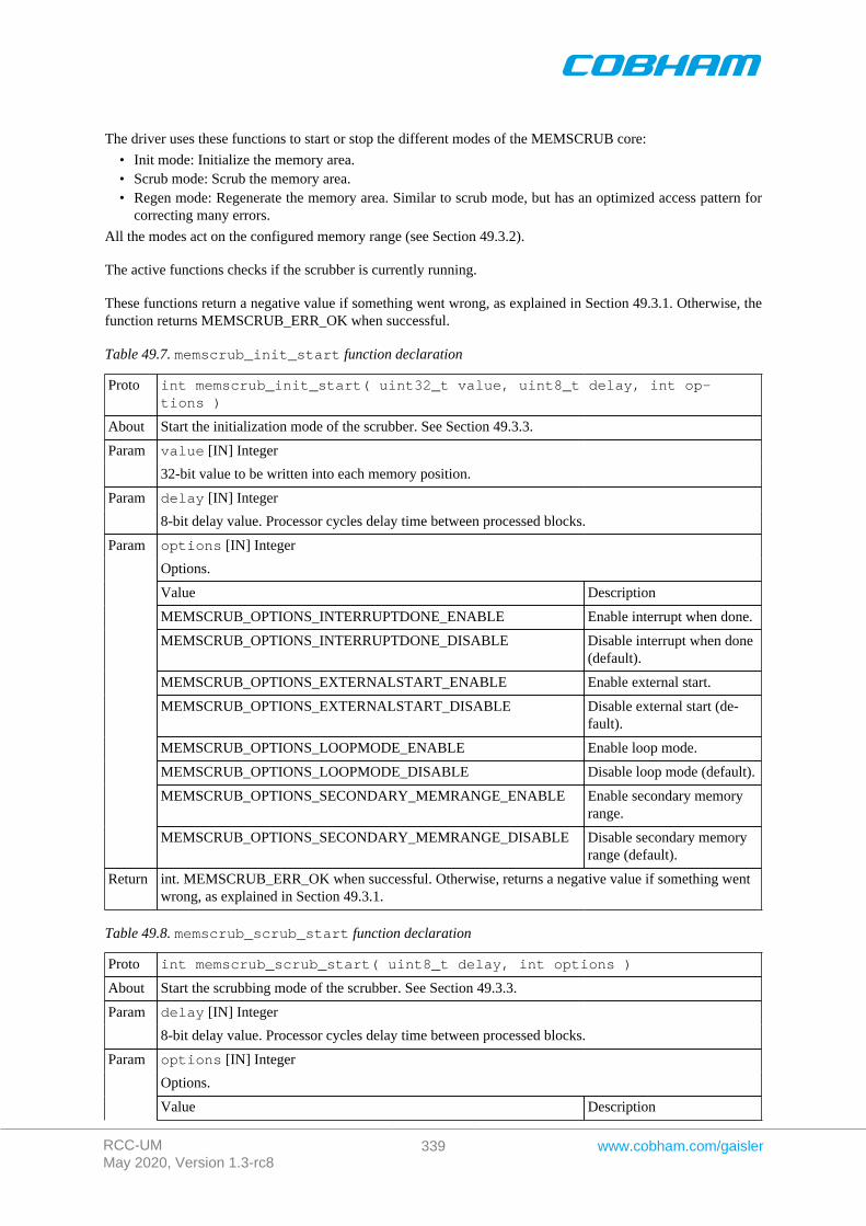
RCC-UMMay 2020, Version 1.3-rc8
339 www.cobham.com/gaisler
The driver uses these functions to start or stop the different modes of the MEMSCRUB core:
• Init mode: Initialize the memory area.• Scrub mode: Scrub the memory area.• Regen mode: Regenerate the memory area. Similar to scrub mode, but has an optimized access pattern for
correcting many errors.
All the modes act on the configured memory range (see Section 49.3.2).
The active functions checks if the scrubber is currently running.
These functions return a negative value if something went wrong, as explained in Section 49.3.1. Otherwise, thefunction returns MEMSCRUB_ERR_OK when successful.
Table 49.7. memscrub_init_start function declaration
Proto int memscrub_init_start( uint32_t value, uint8_t delay, int op-tions )
About Start the initialization mode of the scrubber. See Section 49.3.3.
value [IN] IntegerParam
32-bit value to be written into each memory position.
delay [IN] IntegerParam
8-bit delay value. Processor cycles delay time between processed blocks.
options [IN] Integer
Options.
Value Description
MEMSCRUB_OPTIONS_INTERRUPTDONE_ENABLE Enable interrupt when done.
MEMSCRUB_OPTIONS_INTERRUPTDONE_DISABLE Disable interrupt when done(default).
MEMSCRUB_OPTIONS_EXTERNALSTART_ENABLE Enable external start.
MEMSCRUB_OPTIONS_EXTERNALSTART_DISABLE Disable external start (de-fault).
MEMSCRUB_OPTIONS_LOOPMODE_ENABLE Enable loop mode.
MEMSCRUB_OPTIONS_LOOPMODE_DISABLE Disable loop mode (default).
MEMSCRUB_OPTIONS_SECONDARY_MEMRANGE_ENABLE Enable secondary memoryrange.
Param
MEMSCRUB_OPTIONS_SECONDARY_MEMRANGE_DISABLE Disable secondary memoryrange (default).
Return int. MEMSCRUB_ERR_OK when successful. Otherwise, returns a negative value if something wentwrong, as explained in Section 49.3.1.
Table 49.8. memscrub_scrub_start function declaration
Proto int memscrub_scrub_start( uint8_t delay, int options )
About Start the scrubbing mode of the scrubber. See Section 49.3.3.
delay [IN] IntegerParam
8-bit delay value. Processor cycles delay time between processed blocks.
options [IN] Integer
Options.
Param
Value Description
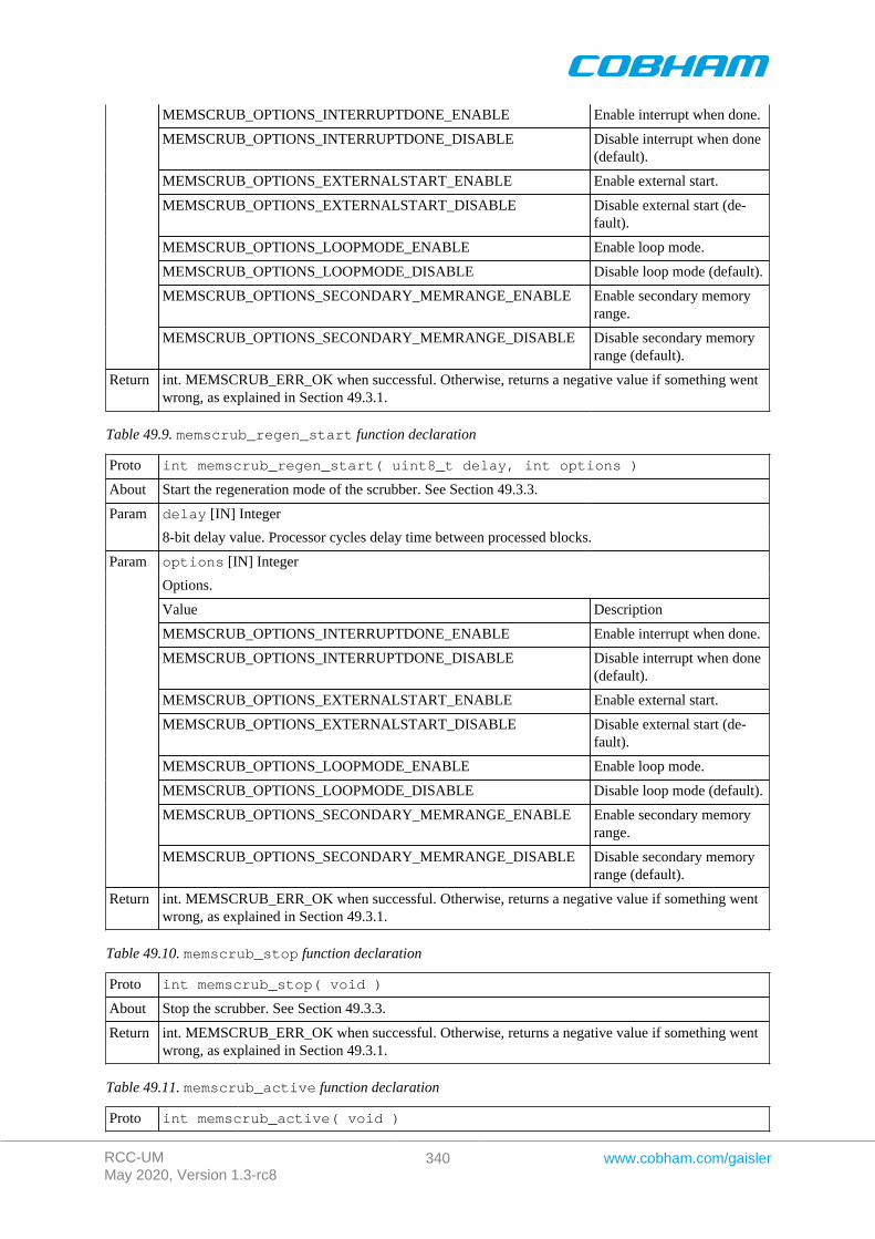
RCC-UMMay 2020, Version 1.3-rc8
340 www.cobham.com/gaisler
MEMSCRUB_OPTIONS_INTERRUPTDONE_ENABLE Enable interrupt when done.
MEMSCRUB_OPTIONS_INTERRUPTDONE_DISABLE Disable interrupt when done(default).
MEMSCRUB_OPTIONS_EXTERNALSTART_ENABLE Enable external start.
MEMSCRUB_OPTIONS_EXTERNALSTART_DISABLE Disable external start (de-fault).
MEMSCRUB_OPTIONS_LOOPMODE_ENABLE Enable loop mode.
MEMSCRUB_OPTIONS_LOOPMODE_DISABLE Disable loop mode (default).
MEMSCRUB_OPTIONS_SECONDARY_MEMRANGE_ENABLE Enable secondary memoryrange.
MEMSCRUB_OPTIONS_SECONDARY_MEMRANGE_DISABLE Disable secondary memoryrange (default).
Return int. MEMSCRUB_ERR_OK when successful. Otherwise, returns a negative value if something wentwrong, as explained in Section 49.3.1.
Table 49.9. memscrub_regen_start function declaration
Proto int memscrub_regen_start( uint8_t delay, int options )
About Start the regeneration mode of the scrubber. See Section 49.3.3.
delay [IN] IntegerParam
8-bit delay value. Processor cycles delay time between processed blocks.
options [IN] Integer
Options.
Value Description
MEMSCRUB_OPTIONS_INTERRUPTDONE_ENABLE Enable interrupt when done.
MEMSCRUB_OPTIONS_INTERRUPTDONE_DISABLE Disable interrupt when done(default).
MEMSCRUB_OPTIONS_EXTERNALSTART_ENABLE Enable external start.
MEMSCRUB_OPTIONS_EXTERNALSTART_DISABLE Disable external start (de-fault).
MEMSCRUB_OPTIONS_LOOPMODE_ENABLE Enable loop mode.
MEMSCRUB_OPTIONS_LOOPMODE_DISABLE Disable loop mode (default).
MEMSCRUB_OPTIONS_SECONDARY_MEMRANGE_ENABLE Enable secondary memoryrange.
Param
MEMSCRUB_OPTIONS_SECONDARY_MEMRANGE_DISABLE Disable secondary memoryrange (default).
Return int. MEMSCRUB_ERR_OK when successful. Otherwise, returns a negative value if something wentwrong, as explained in Section 49.3.1.
Table 49.10. memscrub_stop function declaration
Proto int memscrub_stop( void )
About Stop the scrubber. See Section 49.3.3.
Return int. MEMSCRUB_ERR_OK when successful. Otherwise, returns a negative value if something wentwrong, as explained in Section 49.3.1.
Table 49.11. memscrub_active function declaration
Proto int memscrub_active( void )
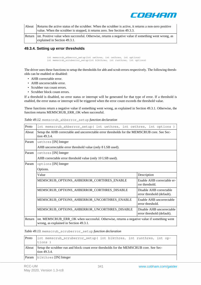
RCC-UMMay 2020, Version 1.3-rc8
341 www.cobham.com/gaisler
About Returns the active status of the scrubber. When the scrubber is active, it returns a non-zero positivevalue. When the scrubber is stopped, it returns zero. See Section 49.3.3.
Return int. Positive value when successful. Otherwise, returns a negative value if something went wrong, asexplained in Section 49.3.1.
49.3.4. Setting up error thresholds
int memscrub_ahberror_setup(int uethres, int cethres, int options) int memscrub_scruberror_setup(int blkthres, int runthres, int options)
The driver uses these functions to setup the thresholds for ahb and scrub errors respectively. The following thresh-olds can be enabled or disabled:
• AHB correctable error.• AHB uncorrectable error.• Scrubber run count errors.• Scrubber block count errors.
If a threshold is disabled, no error status or interrupt will be generated for that type of error. If a threshold isenabled, the error status or interrupt will be triggered when the error count exceeds the threshold value.
These functions return a negative value if something went wrong, as explained in Section 49.3.1. Otherwise, thefunction returns MEMSCRUB_ERR_OK when successful.
Table 49.12. memscrub_ahberror_setup function declaration
Proto int memscrub_ahberror_setup( int uethres, int cethres, int options )
About Setup the AHB correctable and uncorrectable error thresholds for the MEMSCRUB core. See Sec-tion 49.3.4.
uethres [IN] IntegerParam
AHB uncorrectable error threshold value (only 8 LSB used).
cethres [IN] IntegerParam
AHB correctable error threshold value (only 10 LSB used).
options [IN] Integer
Options.
Value Description
MEMSCRUB_OPTIONS_AHBERROR_CORTHRES_ENABLE Enable AHB correctable er-ror threshold.
MEMSCRUB_OPTIONS_AHBERROR_CORTHRES_DISABLE Disable AHB correctableerror threshold (default).
MEMSCRUB_OPTIONS_AHBERROR_UNCORTHRES_ENABLE Enable AHB uncorrectableerror threshold.
Param
MEMSCRUB_OPTIONS_AHBERROR_UNCORTHRES_DISABLE Disable AHB uncorrectableerror threshold (default).
Return int. MEMSCRUB_ERR_OK when successful. Otherwise, returns a negative value if something wentwrong, as explained in Section 49.3.1.
Table 49.13. memscrub_scruberror_setup function declaration
Proto int memscrub_scruberror_setup( int blkthres, int runthres, int op-tions )
About Setup the scrubber run and block count error thresholds for the MEMSCRUB core. See Sec-tion 49.3.4.
Param blkthres [IN] Integer
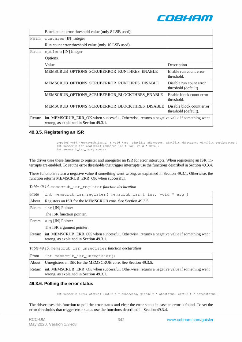
RCC-UMMay 2020, Version 1.3-rc8
342 www.cobham.com/gaisler
Block count error threshold value (only 8 LSB used).
runthres [IN] IntegerParam
Run count error threshold value (only 10 LSB used).
options [IN] Integer
Options.
Value Description
MEMSCRUB_OPTIONS_SCRUBERROR_RUNTHRES_ENABLE Enable run count errorthreshold.
MEMSCRUB_OPTIONS_SCRUBERROR_RUNTHRES_DISABLE Disable run count errorthreshold (default).
MEMSCRUB_OPTIONS_SCRUBERROR_BLOCKTHRES_ENABLE Enable block count errorthreshold.
Param
MEMSCRUB_OPTIONS_SCRUBERROR_BLOCKTHRES_DISABLE Disable block count errorthreshold (default).
Return int. MEMSCRUB_ERR_OK when successful. Otherwise, returns a negative value if something wentwrong, as explained in Section 49.3.1.
49.3.5. Registering an ISR
typedef void (*memscrub_isr_t) ( void *arg, uint32_t ahbaccess, uint32_t ahbstatus, uint32_t scrubstatus ) int memscrub_isr_register( memscrub_isr_t isr, void * data ) int memscrub_isr_unregister()
The driver uses these functions to register and unregister an ISR for error interrupts. When registering an ISR, in-terrupts are enabled. To set the error thresholds that trigger interrupts use the functions described in Section 49.3.4.
These functions return a negative value if something went wrong, as explained in Section 49.3.1. Otherwise, thefunction returns MEMSCRUB_ERR_OK when successful.
Table 49.14. memscrub_isr_register function declaration
Proto int memscrub_isr_register( memscrub_isr_t isr, void * arg )
About Registers an ISR for the MEMSCRUB core. See Section 49.3.5.
isr [IN] PointerParam
The ISR function pointer.
arg [IN] PointerParam
The ISR argument pointer.
Return int. MEMSCRUB_ERR_OK when successful. Otherwise, returns a negative value if something wentwrong, as explained in Section 49.3.1.
Table 49.15. memscrub_isr_unregister function declaration
Proto int memscrub_isr_unregister()
About Unregisters an ISR for the MEMSCRUB core. See Section 49.3.5.
Return int. MEMSCRUB_ERR_OK when successful. Otherwise, returns a negative value if something wentwrong, as explained in Section 49.3.1.
49.3.6. Polling the error status
int memscrub_error_status( uint32_t * ahbaccess, uint32_t * ahbstatus, uint32_t * scrubstatus )
The driver uses this function to poll the error status and clear the error status in case an error is found. To set theerror thresholds that trigger error status use the functions described in Section 49.3.4.
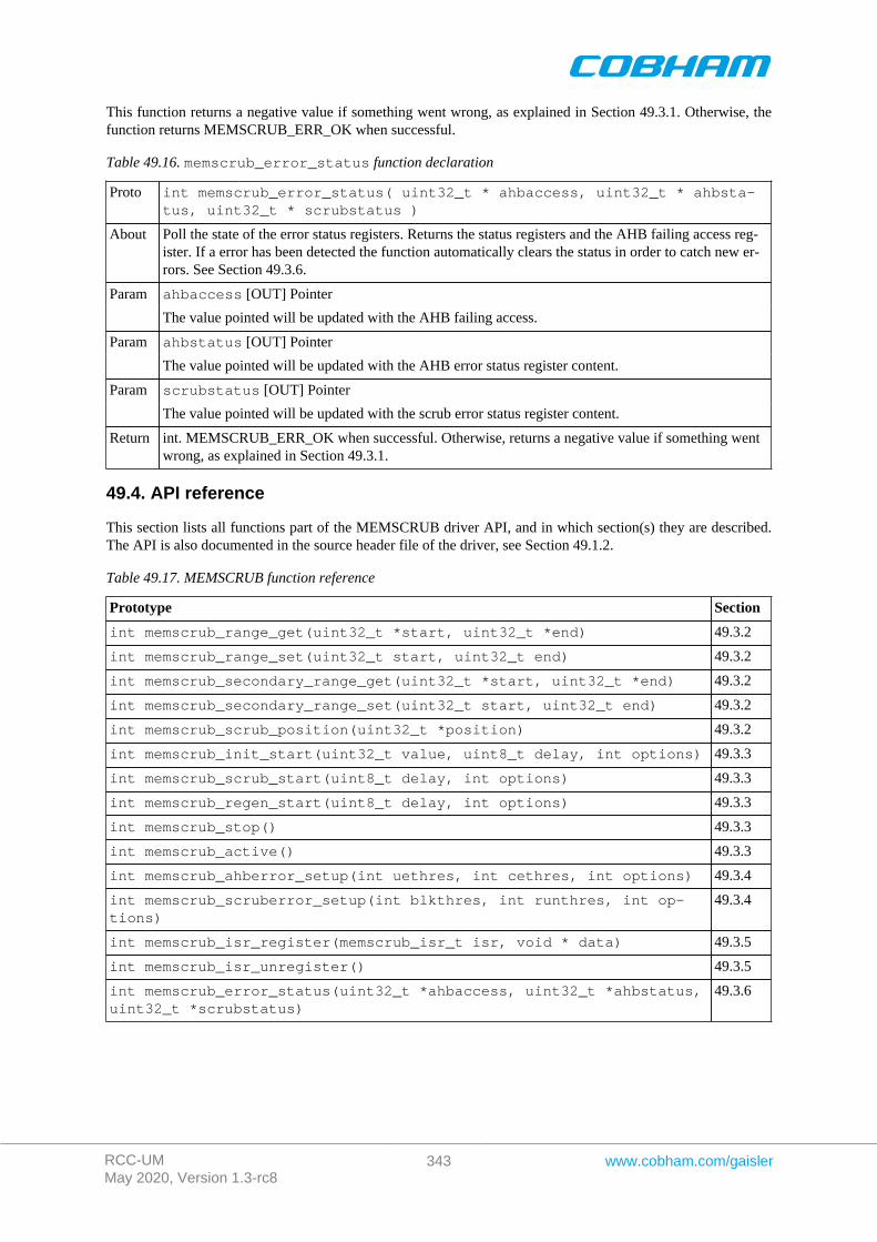
RCC-UMMay 2020, Version 1.3-rc8
343 www.cobham.com/gaisler
This function returns a negative value if something went wrong, as explained in Section 49.3.1. Otherwise, thefunction returns MEMSCRUB_ERR_OK when successful.
Table 49.16. memscrub_error_status function declaration
Proto int memscrub_error_status( uint32_t * ahbaccess, uint32_t * ahbsta-tus, uint32_t * scrubstatus )
About Poll the state of the error status registers. Returns the status registers and the AHB failing access reg-ister. If a error has been detected the function automatically clears the status in order to catch new er-rors. See Section 49.3.6.
ahbaccess [OUT] PointerParam
The value pointed will be updated with the AHB failing access.
ahbstatus [OUT] PointerParam
The value pointed will be updated with the AHB error status register content.
scrubstatus [OUT] PointerParam
The value pointed will be updated with the scrub error status register content.
Return int. MEMSCRUB_ERR_OK when successful. Otherwise, returns a negative value if something wentwrong, as explained in Section 49.3.1.
49.4. API reference
This section lists all functions part of the MEMSCRUB driver API, and in which section(s) they are described.The API is also documented in the source header file of the driver, see Section 49.1.2.
Table 49.17. MEMSCRUB function reference
Prototype Section
int memscrub_range_get(uint32_t *start, uint32_t *end) 49.3.2
int memscrub_range_set(uint32_t start, uint32_t end) 49.3.2
int memscrub_secondary_range_get(uint32_t *start, uint32_t *end) 49.3.2
int memscrub_secondary_range_set(uint32_t start, uint32_t end) 49.3.2
int memscrub_scrub_position(uint32_t *position) 49.3.2
int memscrub_init_start(uint32_t value, uint8_t delay, int options) 49.3.3
int memscrub_scrub_start(uint8_t delay, int options) 49.3.3
int memscrub_regen_start(uint8_t delay, int options) 49.3.3
int memscrub_stop() 49.3.3
int memscrub_active() 49.3.3
int memscrub_ahberror_setup(int uethres, int cethres, int options) 49.3.4
int memscrub_scruberror_setup(int blkthres, int runthres, int op-tions)
49.3.4
int memscrub_isr_register(memscrub_isr_t isr, void * data) 49.3.5
int memscrub_isr_unregister() 49.3.5
int memscrub_error_status(uint32_t *ahbaccess, uint32_t *ahbstatus,uint32_t *scrubstatus)
49.3.6

RCC-UMMay 2020, Version 1.3-rc8
344 www.cobham.com/gaisler
Cobham Gaisler ABKungsgatan 12411 19 GothenburgSwedenwww.cobham.com/[email protected]: +46 31 7758650F: +46 31 421407
Cobham Gaisler AB, reserves the right to make changes to any products and services describedherein at any time without notice. Consult Cobham or an authorized sales representative to verify thatthe information in this document is current before using this product. Cobham does not assume anyresponsibility or liability arising out of the application or use of any product or service described herein,except as expressly agreed to in writing by Cobham; nor does the purchase, lease, or use of a productor service from Cobham convey a license under any patent rights, copyrights, trademark rights, or anyother of the intellectual rights of Cobham or of third parties. All information is provided as is. There is nowarranty that it is correct or suitable for any purpose, neither implicit nor explicit.
Copyright © 2019 Cobham Gaisler AB
Related Documents