Arduino Projects, Libraries and Tutorials Home What is an Arduino ? Project Index Cars Great Projects Saturday, December 1, 2012 Arduino Due DDS - Part 1 - Sinewaves and Fixed Point Maths This post provides a quick introduction to Direct Digital Synthesis (DDS) on the Arduino Due. The sample sketch outputs a sinewave at a 44.1Khz sample rate with 12 bit resolution using the built in Digital To Analog Converter (DAC). A related sketch which provides more interesting audio output without the explanation can be found here - http://rcarduino.blogspot.com/2012/11/quick-and-dirty-synth-for-arduino-due.html All of the Audio projects on RCArduino are based on this same DDS technique described below, see the following links for DDS Projects - http://rcarduino.blogspot.com/2012/10/five-dollar-synthesiser.html http://rcarduino.blogspot.com/2012/08/the-must-build-arduino-project-illutron.html http://rcarduino.blogspot.com/2012/11/auduino-with-delay.html http://rcarduino.blogspot.com/2012/08/adding-audio-to-arduino-projects.html http://rcarduino.blogspot.com/2012/10/arduino-modular-synthesizer-part-one.html Direct Digital Synthesis - Introduction DDS is a common approach to generating sinewave output from digital systems. The approach is based around outputting samples from a description of the required waveform held in memory. The description is an array of samples which can be traversed to plot the waveform onscreen or by using DDS can generate a sinewave output at a selected frequency. The 600 sample 12 Bit sine wave table used in the sketch below plotted on screen using processing - The 128 sample 8 Bit wave tables used in the Illutron B synth - Direct Digital Synthesis - Sample Rate To generate an output waveform we need a way to regularly update the output value, we do this by using a timer interrupt. The frequency of this interrupt is termed the sample rate, in our case we are using a 44.1Khz sample rate meaning that we have an interrupt triggering 44,100 times per second. As this interrupt is triggering at such a high rate it is very important that we keep it efficient, this is the reason for using a pre computed wavetable rather than computing the sine samples on the fly. Direct Digital Synthesis - Frequency Generation We can generate different frequencies by changing the rate at which we traverse through the wave table. One pass through the wavetable provides one complete cycle of the selected waveform (sine in our case). If we pass through the table once in 44,100 interrupts we generate a frequency of 1Hz, if we pass through 100 times faster, we get a sinewave output at a frequency of 100Hz. Direct Digital Synthesis - Implementation and Terminology The following terms are commonly used in reference to DDS and variations are used throughout the RC Arduino audio with Google Friend Connect Members (78) More » Already a member? Sign in Followers Search This Blog Follow by Email How To Read an RC Receiver With A Microcontroller - Part 1 Its a very common question, ' How do I read an RC Receiver with my micro controller ' and the answer is often very simple however t... How To Read RC Receiver PPM Stream Many RC Transmitters and Receivers provide access to the PPM Stream, this is a single stream of pulses which includes the information for a... How To Read Multiple RC Channels This post builds on previous posts to show a technique for reading multiple radio control receiver channels using an Arduino. Update 27/0... Servo Problems With Arduino - Part 1 Servo problems are one of the most frequently posted topics within the Arduino community. While problems may arise from programming, ci... Adding Audio to Arduino Projects Sometimes a project just needs to be louder, whether its a Popular Posts RCArduino: Arduino Due DDS - Part 1 - Sinewaves and Fixed Point ... http://rcarduino.blogspot.in/2012/12/arduino-due-dds-part-1-sinewave... 1 of 13 10 Jan 2014 10:05 AM

RCArduino_ Arduino Due DDS - Part 1 - Sinewaves and Fixed Point Maths
Oct 20, 2015
scc
Welcome message from author
This document is posted to help you gain knowledge. Please leave a comment to let me know what you think about it! Share it to your friends and learn new things together.
Transcript

Arduino Projects, Libraries and Tutorials
Home What is an Arduino ? Project Index Cars Great Projects
Saturday, December 1, 2012
Arduino Due DDS - Part 1 - Sinewaves and Fixed Point Maths
This post provides a quick introduction to Direct Digital Synthesis (DDS) on the Arduino Due. The sample sketch outputs asinewave at a 44.1Khz sample rate with 12 bit resolution using the built in Digital To Analog Converter (DAC).
A related sketch which provides more interesting audio output without the explanation can be found here -http://rcarduino.blogspot.com/2012/11/quick-and-dirty-synth-for-arduino-due.html
All of the Audio projects on RCArduino are based on this same DDS technique described below, see the following links forDDS Projects -http://rcarduino.blogspot.com/2012/10/five-dollar-synthesiser.htmlhttp://rcarduino.blogspot.com/2012/08/the-must-build-arduino-project-illutron.html
http://rcarduino.blogspot.com/2012/11/auduino-with-delay.htmlhttp://rcarduino.blogspot.com/2012/08/adding-audio-to-arduino-projects.htmlhttp://rcarduino.blogspot.com/2012/10/arduino-modular-synthesizer-part-one.html
Direct Digital Synthesis - IntroductionDDS is a common approach to generating sinewave output from digital systems. The approach is based around outputtingsamples from a description of the required waveform held in memory. The description is an array of samples which can betraversed to plot the waveform onscreen or by using DDS can generate a sinewave output at a selected frequency.
The 600 sample 12 Bit sine wave table used in the s ketch below plotted on screen using processing -
The 128 sample 8 Bit wave tables used in the Illutr on B synth -
Direct Digital Synthesis - Sample RateTo generate an output waveform we need a way to regularly update the output value, we do this by using a timer interrupt.The frequency of this interrupt is termed the sample rate, in our case we are using a 44.1Khz sample rate meaning that wehave an interrupt triggering 44,100 times per second.
As this interrupt is triggering at such a high rate it is very important that we keep it efficient, this is the reason for using a precomputed wavetable rather than computing the sine samples on the fly.
Direct Digital Synthesis - Frequency GenerationWe can generate different frequencies by changing the rate at which we traverse through the wave table. One pass throughthe wavetable provides one complete cycle of the selected waveform (sine in our case). If we pass through the table oncein 44,100 interrupts we generate a frequency of 1Hz, if we pass through 100 times faster, we get a sinewave output at afrequency of 100Hz.
Direct Digital Synthesis - Implementation and Termi nologyThe following terms are commonly used in reference to DDS and variations are used throughout the RC Arduino audio
with Google Friend Connect
Members (78) More »
Already a member? Sign in
Followers
Search This Blog
Follow by Email
How To Readan RCReceiver WithAMicrocontroller- Part 1
Its a very common question, 'How do I read an RC Receiverwith my micro controller ' andthe answer is often very simplehowever t...
How To ReadRC ReceiverPPM StreamMany RCTransmittersand Receivers
provide access to the PPMStream, this is a single streamof pulses which includes theinformation for a...
How To Read Multiple RCChannelsThis post builds on previousposts to show a technique forreading multiple radio controlreceiver channels using anArduino. Update 27/0...
ServoProblems WithArduino - Part1Servoproblems are
one of the most frequentlyposted topics within theArduino community. Whileproblems may arise fromprogramming, ci...
Adding Audioto ArduinoProjectsSometimes aproject justneeds to be
louder, whether its a
Popular Posts
RCArduino: Arduino Due DDS - Part 1 - Sinewaves and Fixed Point ... http://rcarduino.blogspot.in/2012/12/arduino-due-dds-part-1-sinewave...
1 of 13 10 Jan 2014 10:05 AM

projects.
1) Phase Accumulator - this is an array index which points to the current sample in the selected wavetable.2) Phase Increment - this value is used to advance the Phase Accumulator each time the interrupt is called.
Example usage of the phase accumulator used inside the timer interrupt to select the next sample in th e wavetable array -
// Update the phase accumulator by adding the phase incrementulPhaseAccumulator += ulPhaseIncrement;
// get the current sample from the sine table using the phase accumulator as the index uint32_t ulOutput = nSineTable[ulPhaseAccumulator>>20];
Direct Digital Synthesis - Fixed Point MathsTo generate a full range of frequencies we will often need to use fractional values for our phase accumulator.
The usual method of working with fractional values is to use the float data type however in DDS we need our interrupts torun as fast as possible. With very few exceptions microcontrollers are not able to process the float data type at high speed,the solution is to use fixed point integer maths.
Fixed Points For Higher Integer PrecisionThere are many applications of fixed point arithmetic but in DDS the main use is to provide increased precision - equivalentto having many decimal points while still using the high speed integer (whole number) data type.
To get extra precision we use more bits than we need to represent our data range. For example the sample code below hasa wave table size of 600 samples so the range of we need for our phase accumulator is 0 to 599.
We can represent this range with 10 bits but if we use 16 bits we have 6 additional bits of precession.
16 Bit Integer
Bit 15 14 13 12 11 10 9 8 7 6 5 4 3 2 1 0
Value 32768 16384 8192 4096 2048 1024 512 256 128 64 32 16 8 4 2 1
Fixed Point 10.6 using 16 BitIntegerBit 15 14 13 12 11 10 9 8 7 6 5 4 3 2 1 0
Value 1024 512 256 128 64 32 16 8 4 2 1 0.5 0.25 0.125 0.0625 0.0313
We use this additional precision to perform fractional addition to the phase accumulator, the 10.6 format gives 1/32precision as the least significant bit.
Fixed point addition - we know its fixed point, the compiler doesn't
// Update the phase accumulator by adding the phase incrementulPhaseAccumulator += ulPhaseIncrement;
This line of code is actually adding two fixed point numbers, part of the trick is that the compiler does not know this, it seesthem simply as two integers which it processes using very fast hardware integer addition.
When we want to use the phase accumulator as the array index, we perform an arithmetic shift six places to the right, thisdrops off the six bits of additional precession and leaves us with a 10 bit integer value for the array index.
// drop the six bits of additional precision and access the remaining 10 bits as an integer array index in the range 0 - 599
uint16_t unOutputValue = sineTable[ulPhaseAccumulator>>6];
The only trick to fixed point maths is to figure out a scheme which will work for your project and stick to it. Remember thecompiler does not know that you are treating part of the number as fractions so the responsibility is on you the programmerto keep consistency.
Fixed Point In The RCArduino DDS Example SketchThe standard data type for the 32 bit Arduino Due is a 32 bit integer, this gives us scope for very high levels of precessionin integer maths. The scheme used for the phase increment and phase accumulator variables in the sample sketch is 12.20(12+20 = 32 Bits) this can be seen in the following line of code where the precision is shifted out to access the pure 12 bitinteger value -
uint32_t ulOutput = nSineTable[ulPhaseAccumulator>>20];
Where ever you see code that makes extensive use of '>>' operations you might be looking at fixed point arithmetic, in afollow up post we will look at how we perform fast fixed point multiplication. This is another key to fast and flexiblesynthesizer engines.
Fixed Point Multiplication is used in Audio synthesis to apply envelopes and amplitude modulation.
Envelope Applied to a DDS sine wave using Fixed Poi nt Maths in the Illutron B Project -
synthesizer, alarm clock,autonomous robot or the RCArduino lap timer. In...
The Must BuildArduino Project- The Illutron BIs there a mustbuild Arduinoproject ?
Something simple that can bebuilt in minutes and tinkeredwith for days or weeks ? Thereis now....
RC ArduinoRobotA low costremotecontrolled robotusing a
standalone Arduino tointerface between a pistol gripRC Transmitter/Rece...
The Problem ( and Solutions )With Arduino InterruptsIf you have ever tried to portan Arduino project that usesinterrupts from one board typeto another, you have probablyexperienced frustr...
RC Channels,L293D MotorDriver - Part 2Calibration AndCode
RCChannelsL293D by DBanks is licensed under aCreative Commons Attribution-NonCommercial-ShareAlike3.0 Unported License . Thefoll...
Can I Control More Than XServos With An Arduino ?Yes, Yes, Yes, infact 'Yes'Twelve Times. The Servolibrary for the Arduino UNOallows the control of upto 12Servos on a single A...
2013 (8)
2012 (55)
December (2)
New Year Projects
Arduino Due DDS - Part 1 -Sinewaves and FixedPoi...
November (6)
October (7)
September (4)
August (8)
July (2)
May (4)
April (4)
March (6)
February (5)
January (7)
2011 (9)
Blog Archive
RCArduino: Arduino Due DDS - Part 1 - Sinewaves and Fixed Point ... http://rcarduino.blogspot.in/2012/12/arduino-due-dds-part-1-sinewave...
2 of 13 10 Jan 2014 10:05 AM

DDS Sinewave for Arduino Due - The SketchUse a potentiometer connected to analog pin 0 to control the pitch. To hear the output you can use an amplifier circuit suchas this one used throughout RCArduino -
http://rcarduino.blogspot.com/2012/08/adding-audio-to-arduino-projects.html
The sinewave is output through DAC0 - Note that the DAC does not provide a full 0-3.3volt swing, this is a hardwarelimitation of the SAM3X8E chip.
Caution : The SAM3X8E microcontroller at the heart of the Arduino Due is less able to sink and source current than theAVR family of chips used in the 8-Bit Arduinos. See the update below for the most recent recommendations -
Update 09/06/2013 - Gaétan Ro has taken things much further in the latest build of his Groovuino project. The Project usesthe technique described here combined with some sensors, a sequencer and filter to produce a really nice soundinggroovebox. I plan to build one of these for myself and hope to be able to help Gaétan with its further development.
http://www.youtube.com/watch?v=EqI2hEVbMPI
Gaéta's blog - http://groovuino.blogspot.com/
Update 28/03/2013 : There is little information on the SAM3X8E DAC in the datasheet however Arduino forum used'stimmer' has found recommendations on a closely related chip which suggest that a 2K Ohm resistor should be placed asa series current limiting resistor between the DAC Output and the load. This assumes that the load has no resistance of itsown which will be the case if you accidentally short something, if you know the resistance of your load, you can reduce thisvalue, if not, its a reasonable starting point and will protect against accidents. For more information see the original threadhere - http://arduino.cc/forum/index.php/topic,139733.15.html
Update 28/03/2013 : Gaétan Ro has been building on the techniques here to produce an Arduino Due based groove boxhe is calling the 'Groovuino'. You can hear a clip of the project in action here -
https://soundcloud.com/gaetino/groovuino
And follow the future development on the blog Gaétan has started here -
http://groovuino.blogspot.ae/
// RCArduino DDS Sinewave for Arduino Due// RCArduino DDS Sinewave by RCArduino is licensed under a Creative Commons Attribution 3.0 Unported License.// Based on a work at rcarduino.blogspot.com.
// For helpful background information on Arduino Due Timer Configuration, refer to the following link// thanks to Sebastian Vik// http://arduino.cc/forum/index.php?action=post;topic=130423.15;num_replies=20
// For background information on the DDS Technique see// http://interface.khm.de/index.php/lab/experiments/arduino-dds-sinewave-generator/
// For audio sketches making extensive use of DDS Techniques, search the RCArduino Blog// for the tags Audio or synth
// These are the clock frequencies available to the timers /2,/8,/32,/128// 84Mhz/2 = 42.000 MHz// 84Mhz/8 = 10.500 MHz// 84Mhz/32 = 2.625 MHz// 84Mhz/128 = 656.250 KHz//// 44.1Khz = CD Sample Rate// Lets aim for as close to the CD Sample Rate as we can get -//// 42Mhz/44.1Khz = 952.38// 10.5Mhz/44.1Khz = 238.09 // best fit divide by 8 = TIMER_CLOCK2 and 238 ticks per sample// 2.625Hmz/44.1Khz = 59.5// 656Khz/44.1Khz = 14.88
// 84Mhz/44.1Khz = 1904 instructions per tick
// the phase accumulator points to the current sample in our wavetableuint32_t ulPhaseAccumulator = 0;// the phase increment controls the rate at which we move through the wave table// higher values = higher frequenciesvolatile uint32_t ulPhaseIncrement = 0; // 32 bit phase increment, see below
// full waveform = 0 to SAMPLES_PER_CYCLE// Phase Increment for 1 Hz =(SAMPLES_PER_CYCLE_FIXEDPOINT/SAMPLE_RATE) = 1Hz
RCArduino: Arduino Due DDS - Part 1 - Sinewaves and Fixed Point ... http://rcarduino.blogspot.in/2012/12/arduino-due-dds-part-1-sinewave...
3 of 13 10 Jan 2014 10:05 AM
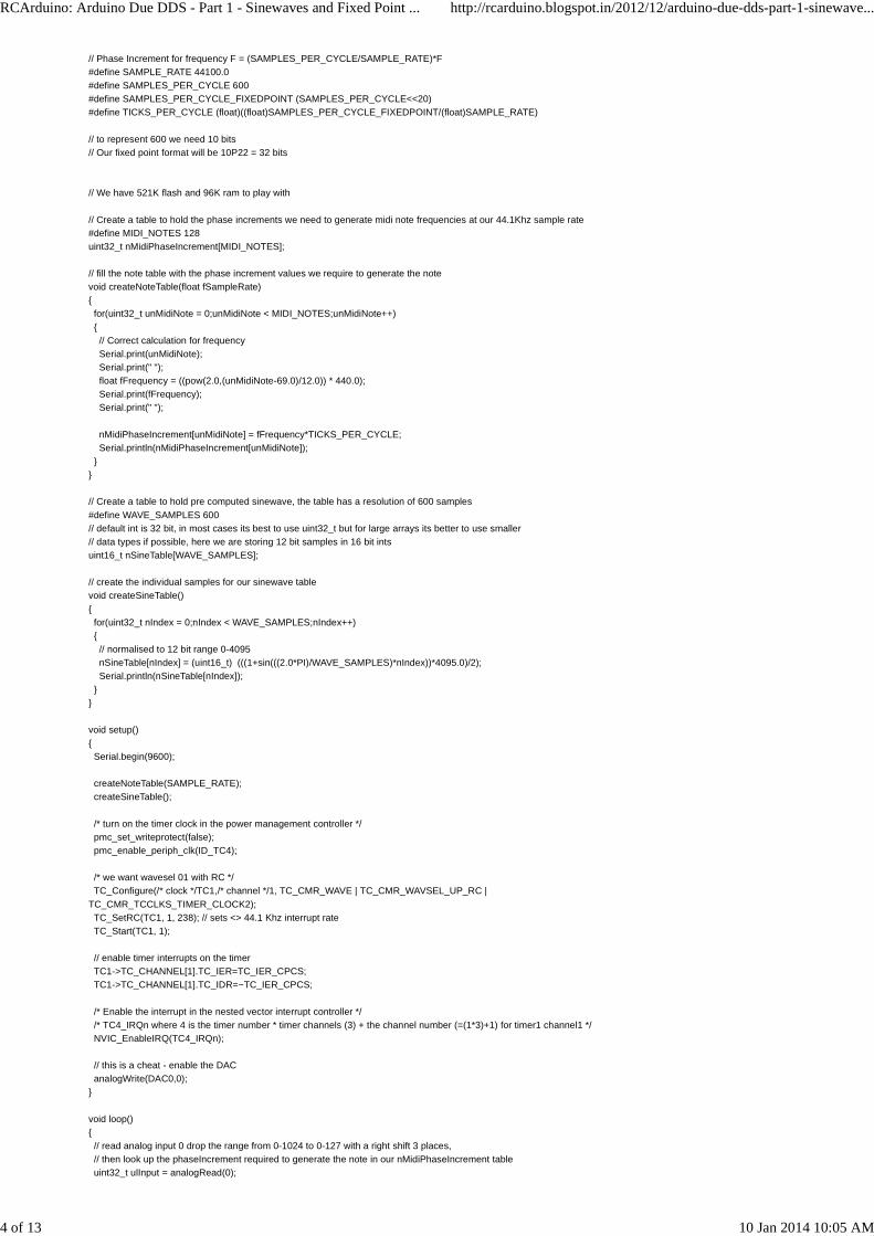
// Phase Increment for frequency F = (SAMPLES_PER_CYCLE/SAMPLE_RATE)*F#define SAMPLE_RATE 44100.0#define SAMPLES_PER_CYCLE 600#define SAMPLES_PER_CYCLE_FIXEDPOINT (SAMPLES_PER_CYCLE<<20)#define TICKS_PER_CYCLE (float)((float)SAMPLES_PER_CYCLE_FIXEDPOINT/(float)SAMPLE_RATE)
// to represent 600 we need 10 bits// Our fixed point format will be 10P22 = 32 bits
// We have 521K flash and 96K ram to play with
// Create a table to hold the phase increments we need to generate midi note frequencies at our 44.1Khz sample rate#define MIDI_NOTES 128uint32_t nMidiPhaseIncrement[MIDI_NOTES];
// fill the note table with the phase increment values we require to generate the notevoid createNoteTable(float fSampleRate){ for(uint32_t unMidiNote = 0;unMidiNote < MIDI_NOTES;unMidiNote++) { // Correct calculation for frequency Serial.print(unMidiNote); Serial.print(" "); float fFrequency = ((pow(2.0,(unMidiNote-69.0)/12.0)) * 440.0); Serial.print(fFrequency); Serial.print(" "); nMidiPhaseIncrement[unMidiNote] = fFrequency*TICKS_PER_CYCLE; Serial.println(nMidiPhaseIncrement[unMidiNote]); }}
// Create a table to hold pre computed sinewave, the table has a resolution of 600 samples#define WAVE_SAMPLES 600// default int is 32 bit, in most cases its best to use uint32_t but for large arrays its better to use smaller// data types if possible, here we are storing 12 bit samples in 16 bit intsuint16_t nSineTable[WAVE_SAMPLES];
// create the individual samples for our sinewave tablevoid createSineTable(){ for(uint32_t nIndex = 0;nIndex < WAVE_SAMPLES;nIndex++) { // normalised to 12 bit range 0-4095 nSineTable[nIndex] = (uint16_t) (((1+sin(((2.0*PI)/WAVE_SAMPLES)*nIndex))*4095.0)/2); Serial.println(nSineTable[nIndex]); }}
void setup(){ Serial.begin(9600);
createNoteTable(SAMPLE_RATE); createSineTable(); /* turn on the timer clock in the power management controller */ pmc_set_writeprotect(false); pmc_enable_periph_clk(ID_TC4);
/* we want wavesel 01 with RC */ TC_Configure(/* clock */TC1,/* channel */1, TC_CMR_WAVE | TC_CMR_WAVSEL_UP_RC |TC_CMR_TCCLKS_TIMER_CLOCK2); TC_SetRC(TC1, 1, 238); // sets <> 44.1 Khz interrupt rate TC_Start(TC1, 1); // enable timer interrupts on the timer TC1->TC_CHANNEL[1].TC_IER=TC_IER_CPCS; TC1->TC_CHANNEL[1].TC_IDR=~TC_IER_CPCS; /* Enable the interrupt in the nested vector interrupt controller */ /* TC4_IRQn where 4 is the timer number * timer channels (3) + the channel number (=(1*3)+1) for timer1 channel1 */ NVIC_EnableIRQ(TC4_IRQn);
// this is a cheat - enable the DAC analogWrite(DAC0,0);}
void loop(){ // read analog input 0 drop the range from 0-1024 to 0-127 with a right shift 3 places, // then look up the phaseIncrement required to generate the note in our nMidiPhaseIncrement table uint32_t ulInput = analogRead(0);
RCArduino: Arduino Due DDS - Part 1 - Sinewaves and Fixed Point ... http://rcarduino.blogspot.in/2012/12/arduino-due-dds-part-1-sinewave...
4 of 13 10 Jan 2014 10:05 AM

Posted by Can_I_Trade? at 11:27 AM
Labels: Arduino Due, Arduino Due Library, Audio, DDS, Direct Digital Synthesis, sin, sin wave, Sine wave, sinewave, waveform
ulPhaseIncrement = nMidiPhaseIncrement[ulInput>>3];}
void TC4_Handler(){ // We need to get the status to clear it and allow the interrupt to fire again TC_GetStatus(TC1, 1); ulPhaseAccumulator += ulPhaseIncrement; // 32 bit phase increment, see below
// if the phase accumulator over flows - we have been through one cycle at the current pitch, // now we need to reset the grains ready for our next cycle if(ulPhaseAccumulator > SAMPLES_PER_CYCLE_FIXEDPOINT) { // DB 02/Jan/2012 - carry the remainder of the phase accumulator ulPhaseAccumulator -= SAMPLES_PER_CYCLE_FIXEDPOINT; }
// get the current sample uint32_t ulOutput = nSineTable[ulPhaseAccumulator>>20]; // we cheated and user analogWrite to enable the dac, but here we want to be fast so // write directly dacc_write_conversion_data(DACC_INTERFACE, ulOutput);}
Replies
Reply
48 comments:
Neutronium December 17, 2012 at 8:38 AM
i think there might be something wrong, it appears that the output frequency is locked to the ISR frequency. at the highestposition on the pot i am using to test, i get 11.03 khz,(probably 11.025 but my scope only has 2 decimal places for frequency)then as you gradually turn the voltage down, you see the waveform change but it doesnt change frequency till it skips to 8.82khz.
also when i toggle a digital out on the ISR, and use it for scope sync, it is always steady when im using sync on the outputwaveform. i would expect it to move around a bit
best regards
neutron7
Reply
Can_I_Trade? December 17, 2012 at 10:39 AM
Hi,The ISR operates at a fixed frequency of 44.1khz, which does not change regardless of the selected frequency. As for theoutput frequency, Try replacing the line that reads your input potentiometer with one that just sets ulInput to 69 which is MiddleA on the piano, You should see an output frequency of 440hz.
let me know
Duane B
Reply
Neutronium December 17, 2012 at 11:06 AM
i was hoping to make it voltage controllable as well, so i made it a bit more like Adrian Freeds version. i changed the number ofsamples to 512, that way the "reset to zero if over SAMPLES_PER_CYCLE_FIXEDPOINT" can be removed, and it naturallyrolls over when the phase accumulator passes the highest number in a 32 bit integer.then you get the "proper" remainderadded to zero and the wave doesn't hard sync to the sample rate.
I had to tweak a couple of other things but it doesnt actually seem that much different to my "old arduino" lo fi version.
http://www.youtube.com/watch?v=2BHwqN3VnFw
Reply
Can_I_Trade? January 2, 2013 at 11:22 AM
Hi, I have updated the ISR to carry the remainder of the phase accumulator - removing the hard synch and alsoallowing for sample rates that are not powers of 2
Duane B
Neutronium December 17, 2012 at 11:09 AM
RCArduino: Arduino Due DDS - Part 1 - Sinewaves and Fixed Point ... http://rcarduino.blogspot.in/2012/12/arduino-due-dds-part-1-sinewave...
5 of 13 10 Jan 2014 10:05 AM

thanks for pioneering work in getting the DUE to make waves like i was hoping it would! i can skip almost all the externalcircuitry now!
Reply
Can_I_Trade? December 17, 2012 at 12:38 PM
Hi, I went with the unconventional 600 sample waveforms because I am planning to experiment with the huge waveformcollection that adventure kid has made available. I have them on an SD Card connected to the due at the moment. Here is alink to the waveform collections - http://www.adventurekid.se/akrt/waveforms/adventure-kid-waveforms/
Duane B
Reply
Gaétan Ro February 4, 2013 at 1:46 AM
Hello, The waveforms on adventurekid are .wav files. Did you find a "simple" way to convert them into a list of 16 bits numbers,and then convert them to 12 bit ?
Gaétan
Reply
Can_I_Trade? February 4, 2013 at 2:15 AM
Hi,What I intended to do was open the files in thier original form from an SD Card attached to the Due, read the headers to findthe start of the actual waveform data and then just import that part to memory. In the short term I did something similar whichwas a bit fo a hack. I slowed down on this project for two reasons 1) The DAC Output of my Due died, this is a commonproblem so be careful, try and use a 500 Ohm resistor whenever you connect the DAC to anything. 2) The waveforms aredifferent shades of the same thing, I didn't have any immediate ideas of how to build something interesting with them - I am nota musician - and so I went back to trying to get more interesting Audio out of the 8-bit Arduinos. Let me know if you come upwith something.
Duane.
Reply
Gaétan Ro February 4, 2013 at 5:15 AM
I reassure you, I'm a musician, but me neither I don't know how to make interesting waveforms (you would have to bemathemusician maybe). I thougth too to read wav files on SD card, but if I could integrate some waveforms directly in thearduino memory, it could be great. It's possible to write a little program in Python or with Processing to do this, but if it alreadyexists... anyway, I will tell you when I find, or write a program.Thanks for the caution about DAC output. I didn't manage to have DAC0 working, but DAC1 is playing well in my mixer since aweek without a resistor. I will put one anyway just in case.I made a synth with 3 Osc, 4 voices polyphony, enveloppes, LFO, filter in 44100 with your tutos and Mozzi, and now try to loadmore waveforms.Due is... WoW ! so more powerfull than Uno !
Reply
Gaétan Ro February 4, 2013 at 5:43 AM
Ah sorry, I realize I misunderstood what you said about waveforms (scuse me, I'm french).
In fact, a single waveform is not so interesting, because if you have several simple oscillators, you can build anyway all sorts ofwaveforms by mixing, detuning, saturating, ring modulating the simple waveforms sawtooth, triangle, sine and square.Waveforms it's as you buy a statue instead of clay. It's the only interest.But it's not the frequence form of a sound we hear which is interesting, it's its evolution in the time. And for that, wavetable isVERY interesting. It's a table of waveforms, which can make a more complex, evoluting sound, like a human voice forexemple.Waveform can only make whistle, or flute sound for exemple.The principle :Program loop on the first waveform, then when certain time is passed read the second waveform, etc... until the last waveform,which will make transition to the first waveform.It's loops in loops.You can change speed of wavetable loop (change the speed of the "phrase") or/and speed of waveforms (change the note).
It's very difficult to build a wavetable, but one way is by applying morphing to waveforms, so it's interesting to have a lot ofwaveforms.
Hope I was clear
Reply
Can_I_Trade? February 4, 2013 at 7:31 AM
Hi, Your right and thats the problem, we would essentially be building 12 bit versions of techniques that have already been builtat higher resolution on better hardware, for example the Korg Ms-10 running on Nintendo DS or the Ms-20 on IPad. Thatspartly why I went back to 8-bits its more accessible and more enjoyable to see how you can make something that sounds newand interesting within the limitations. Duane
Reply
Can_I_Trade? February 4, 2013 at 8:20 AM
And here it is, the Nintendo Korg DS-10http://www.youtube.com/watch?v=8UB1AZPXJoA
RCArduino: Arduino Due DDS - Part 1 - Sinewaves and Fixed Point ... http://rcarduino.blogspot.in/2012/12/arduino-due-dds-part-1-sinewave...
6 of 13 10 Jan 2014 10:05 AM
Pocket sized power.
Duane B
Reply
Gaétan Ro February 4, 2013 at 8:25 AM
That's true about synthesis.But about 12bit sampling, it's another story. A lot of Akai samplers from 80-90's which were 12bit have a sound still popular(and expensive !).With Due I think you can make this kind of samplers (except DAC maybe) and you can use SD cards to store samples ! Andthere's a lot to do to improve human-machine interface for low-cost (NDS touchscreen 2$, distance sensors 8 $, LED matrix 2$, etc).
For me Ms-10 has not enough functionalities, and Ms-20 interface is too complicated... and they don't tempt me on makingmusic, unlike simple things like monotron, or Korg i-kaossilator (speaking about ipad).
Like you say, "cheap sound generators" like 8-bit still have its interests, and I think the most important will be interface andworkflow.
Speaking about nice effects on 8 bit, I tried LowPassFilter from Mozzi, and it's working pretty well :
// set feedback amount given f and q between 0 and 1fb = q + q/(1.0 - f);
// for each sample...buf0 = buf0 + f * (in - buf0 + fb * (buf0 - buf1));buf1 = buf1 + f * (buf0 - buf1);out = buf1;
Beginning with buf0=0
I don't know how it works,... but it works !
Reply
Can_I_Trade? February 4, 2013 at 8:37 AM
Hi, True, the option of carrying around a pocket sampler with a nice playback interface would be great. I have a monotron anlove that its pick up and play and that there are so many sounds to explore - mainly from the filter. I was going to ask you aboutthe Mozzi filter, I have been messing around with the hardware filter on the Nebulophone but its a bit on/off so will have a lookat Mozzi.
Duane
Reply
Gaétan Ro February 5, 2013 at 7:07 AM
OK, I made a little Processing (very non-optimized code, but don't care) which can print out samples of a mono-16bit .wav file,in a txt file, with 12bit values (between 0 and 4096).I tried with some of adventurekid waveforms, and it works (except some extra strange value at the end of the file, you can justcut them).So now, I can load directly the samples in the memory of the Arduino.Here is the Processing code without commentaries :
// Change the name of the wave file of the wave formbyte b[] = loadBytes("AKWF_sin_0001.wav");
int buf;
PrintWriter wavtab = createWriter("wavtable.txt");;
String output = "";
print("AudioFormat ");println (b[20]);print("NumChannels ");println (b[22]);buf = (b[24]&0xff)+(b[25]&0xff)*256;print("SampleRate ");println(buf);
for (int i = 44; i < b.length; i+=2) {
int a1 = b[i] ;int a2 = b[i+1] ;float a3 = ((a1+128)+(a2*256)+32768)/16;int out = (int)a3;output = output + out;
wavtab.print(output);wavtab.println(",");output = "";
}
RCArduino: Arduino Due DDS - Part 1 - Sinewaves and Fixed Point ... http://rcarduino.blogspot.in/2012/12/arduino-due-dds-part-1-sinewave...
7 of 13 10 Jan 2014 10:05 AM
Replies
Reply
Replies
wavtab.flush();
Reply
Anonymous February 7, 2013 at 1:27 PM
Gaétan Ro:
You can avoid picking up the "strange values" at the end of the adventurekid .wav files by restricting the values tothe actual the data chunk. There's a 4-byte integer starting at index 40 that describes the length of the data chunk.If you decode that value, and call it, say, dataLength, and change this line:for (int i = 44; i < b.length; i+=2) {to this:for (int i = 44; i < dataLength; i+=2) {then you won't see the extraneous values.
Those extraneous data are actually a "Sample" chunk, added to the file after the data chunk. It's intended todescribe how a MIDI sampling instrument should use the .wav sample data in the data chunk. All of theadventurekid files I've looked at have identical sample chunks. Most of the fields are blank. The sample chunk saysthat the duration of the sample is 22675 nanoseconds, and that the sample starts at index 0 and runs to index 599,all of which seems to be correct. However, it also appears to claim that the note is MIDI note number 60, middle C.Based on the sample length of 600 at 44.1kHz, I calculate a fundamental frequency of 73.5 Hz, close to a D2,almost two octaves below middle C. That part appears to be incorrect.
Can_I_Trade? February 8, 2013 at 2:20 AM
Hi for a single cycle waveform the frequency comes from how fast you cycle through the samples, there is nothingin the samples themselves that relates to frequency. I assume that its a different case in a synth where you mightpick different versions of the waveform depending on the note, for example a low note on a saxophone would havea different waveform than a note four octaves higher - thats my guess anyway.Duane B
Anonymous February 8, 2013 at 8:15 AM
Indeed, there's nothing about the sample that forces you to use it at any particular frequency for a DDSimplementation.
In the adventurekid .wav files, though, there is some data beyond the actual samples - the "extra strange value atthe end of the file" noted by Gaétan Ro, above. That data is called a "sample chunk." It's purpose is to tell a MIDIdevice how to use the samples in the file. One of the parameters that the sample chunk defines is the MIDI notenumber that corresponds to the tone that would be produced by delivering the samples at the rate defined in thefile's format chunk - in this case, 44100 Hz. The note number shown in the sample chunk is 60, which is middle C,or C4. The files all contain 600 samples, for a period of about 13.6 ms, and a frequency of 73.5 Hz, precisely.That's a little higher than the canonical frequency of about 73.4 Hz for D2 - a long way from C4. So, note 60 looksto me to be incorrect for these files.
My intent is simply to describe how to avoid picking up the "extra" data beyond the actual samples, and to describewhat that extra data is. Having described it, it seems prudent to mention that the data looks to have a quirk. I don'tknow whether any MIDI devices ever use the data in a "sample chunk" in practice, but, if they do, then using thesefiles in such a device may lead to unexpected results.
Can_I_Trade? February 10, 2013 at 8:53 PM
Thanks for the clarification,
Duane B
Gaétan Ro February 13, 2013 at 4:53 AM
Thanks too. I didn't see in wave file descriptions that it could contain chunks after the sound data.In case of waveforms, the file always represents one cycle, so the frequency only depends on sample length.Indeed, as you said, the extra data is not usefull.
Can_I_Trade? February 5, 2013 at 9:51 AM
Hi,If you look through the examples that are supplied with the Arduino SD Card library there are some that traverse a directorytree listing all files. You could adapt your code and one of these sketches to convert all of the .wav files on an SD Card into aDue friendly format. You would then be able to pick any one of 1,000s of waveforms into memory whenever you needed it.
Duane B
Reply
Gaétan Ro February 6, 2013 at 12:59 AM
Hello,Yeah, good idea ! I did this directly with Processing, to generate .h files I put in my arduino sketch.I tried to add some of these waveforms in the code, but I think it overloads my memory. I apply the system you useto load 600 occurs tables. With the three first (sine, saw, square) it's ok, but when I add a waveform, arduinocrashes (if I add only a 300 samples waveform it's ok, but with 600 samples, it crashes). The tables of 600 2-bytesintegers would take 1,2k RAM memory. Due has 96k of RAM, so I thought I could store at least a dozen ofwaveforms in RAM, but I must be missing something...
RCArduino: Arduino Due DDS - Part 1 - Sinewaves and Fixed Point ... http://rcarduino.blogspot.in/2012/12/arduino-due-dds-part-1-sinewave...
8 of 13 10 Jan 2014 10:05 AM

Reply
Replies
Reply
Replies
The code is like this :
int wave[600];
void waveform(){wave[0]= aaaa;wave[1]= bbbb;...wave[599]=cccc;}
Can_I_Trade? February 6, 2013 at 7:17 AM
Hi,I used functions to fill the wavetables because the functions were calculating the values. If you already know the values whichin your case you do, you can create the arrays directly using the values. If you have a look at the Auduino with delay here -http://rcarduino.blogspot.com/2012/11/auduino-with-delay.html you will see how the antilogTable and midiTable are createdand initialised directly with their values.
This might not fix things immediatley, but it is a more conventional approach to creating arrays when you know the values inadvance.
Duane B
Reply
Gaétan Ro February 7, 2013 at 2:53 AM
Thanks, it's working now! I don't know why, because it should take the same RAM. Maybe because the binarymodule takes a lot less flash memory...When I added a dozen of waveforms, I had to lower my polyphony (I had 4 notes polyphony with 3 osc per voice, itwas too much for the poor Due). Now with 2 notes polyphony it's ok. My code is not yet totaly optimized. Forexemple, I compute filter with float (I tried to convert in 32bit integers with the technique you explained in an otherpost, but it didn't work), but can say that Due is powerfull enough to be a good synth.
But can it be a sampler ? With 96k of RAM, I can store... 2 seconds of mono wavefile at 44kHz. Not enough, evenwith single drum-shots. I see two other solutions :. Reading directly the SD card. But is it quick enough to play in realtime ?. Storing in the flash memory. I saw in the Due specs that you can store data in the flash memory instead of RAM.There would be 512k, that is more acceptable. But I couldn't load other samples after the boot of Arduino.
Can_I_Trade? February 7, 2013 at 3:09 AM
Hi,I think the Due can be a practical sampler. The DUE has direct memory access capabilities which run in the background andcan perform extremely fast transfers to and from external memory including SD Cards. I have no experience with this, but Ibeleive that SD Cards are available in different classes with different speed ratings, the higher speed cards have massive datatransfer rates and so does the Due when using DMA. There are some related posts on the Arduino forum if you search in theDue section for 'SDFat'
Duane
Reply
Can_I_Trade? February 7, 2013 at 3:10 AM
Are you using the Mozzi filter or something else ? I want to try afilter this weekend
Duane
Reply
Gaétan Ro February 7, 2013 at 4:43 AM
Yes, Mozzi filter. Very musical filter.How I added it in your sketch :
float f=0.5;float fb;float q=0.3;float buf0 = 0;float buf1 = 0 ;
setup(){....fb = q+q/(1.0 - f);}
float nextfilter(float in)
RCArduino: Arduino Due DDS - Part 1 - Sinewaves and Fixed Point ... http://rcarduino.blogspot.in/2012/12/arduino-due-dds-part-1-sinewave...
9 of 13 10 Jan 2014 10:05 AM
Reply
Replies
Reply
{buf0 = buf0 + f*(in-buf0 + fb*(buf0-buf1));buf1 = buf1 + f*(buf0-buf1);
return (buf1*4096);}
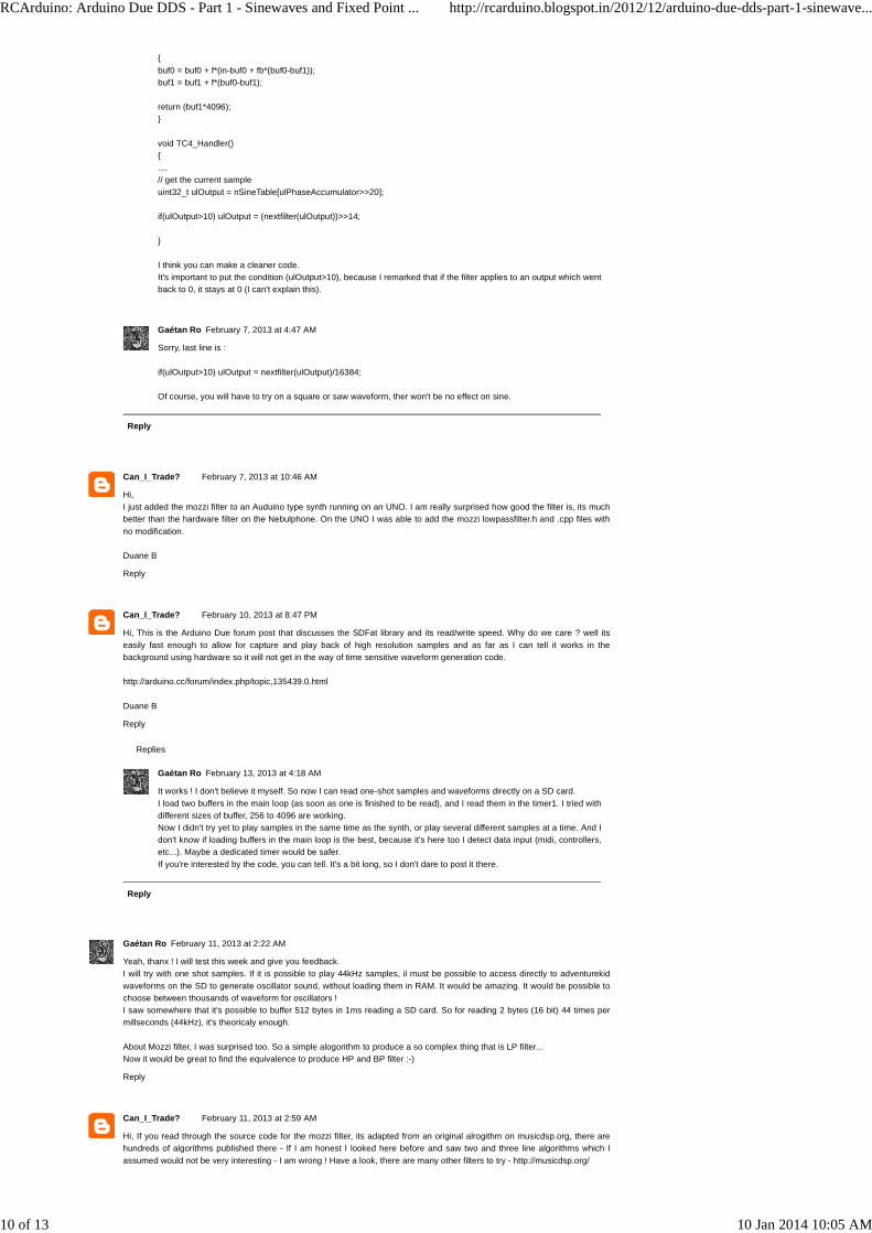
void TC4_Handler(){....// get the current sampleuint32_t ulOutput = nSineTable[ulPhaseAccumulator>>20];
if(ulOutput>10) ulOutput = (nextfilter(ulOutput))>>14;
}
I think you can make a cleaner code.It's important to put the condition (ulOutput>10), because I remarked that if the filter applies to an output which wentback to 0, it stays at 0 (I can't explain this).
Gaétan Ro February 7, 2013 at 4:47 AM
Sorry, last line is :
if(ulOutput>10) ulOutput = nextfilter(ulOutput)/16384;
Of course, you will have to try on a square or saw waveform, ther won't be no effect on sine.
Can_I_Trade? February 7, 2013 at 10:46 AM
Hi,I just added the mozzi filter to an Auduino type synth running on an UNO. I am really surprised how good the filter is, its muchbetter than the hardware filter on the Nebulphone. On the UNO I was able to add the mozzi lowpassfilter.h and .cpp files withno modification.
Duane B
Reply
Can_I_Trade? February 10, 2013 at 8:47 PM
Hi, This is the Arduino Due forum post that discusses the SDFat library and its read/write speed. Why do we care ? well itseasily fast enough to allow for capture and play back of high resolution samples and as far as I can tell it works in thebackground using hardware so it will not get in the way of time sensitive waveform generation code.
http://arduino.cc/forum/index.php/topic,135439.0.html
Duane B
Reply
Gaétan Ro February 13, 2013 at 4:18 AM
It works ! I don't believe it myself. So now I can read one-shot samples and waveforms directly on a SD card.I load two buffers in the main loop (as soon as one is finished to be read), and I read them in the timer1. I tried withdifferent sizes of buffer, 256 to 4096 are working.Now I didn't try yet to play samples in the same time as the synth, or play several different samples at a time. And Idon't know if loading buffers in the main loop is the best, because it's here too I detect data input (midi, controllers,etc...). Maybe a dedicated timer would be safer.If you're interested by the code, you can tell. It's a bit long, so I don't dare to post it there.
Gaétan Ro February 11, 2013 at 2:22 AM
Yeah, thanx ! I will test this week and give you feedback.I will try with one shot samples. If it is possible to play 44kHz samples, il must be possible to access directly to adventurekidwaveforms on the SD to generate oscillator sound, without loading them in RAM. It would be amazing. It would be possible tochoose between thousands of waveform for oscillators !I saw somewhere that it's possible to buffer 512 bytes in 1ms reading a SD card. So for reading 2 bytes (16 bit) 44 times permillseconds (44kHz), it's theoricaly enough.
About Mozzi filter, I was surprised too. So a simple alogorithm to produce a so complex thing that is LP filter...Now it would be great to find the equivalence to produce HP and BP filter :-)
Reply
Can_I_Trade? February 11, 2013 at 2:59 AM
Hi, If you read through the source code for the mozzi filter, its adapted from an original alrogithm on musicdsp.org, there arehundreds of algorithms published there - If I am honest I looked here before and saw two and three line algorithms which Iassumed would not be very interesting - I am wrong ! Have a look, there are many other filters to try - http://musicdsp.org/
RCArduino: Arduino Due DDS - Part 1 - Sinewaves and Fixed Point ... http://rcarduino.blogspot.in/2012/12/arduino-due-dds-part-1-sinewave...
10 of 13 10 Jan 2014 10:05 AM

Reply
Can_I_Trade? February 11, 2013 at 3:12 AM
The original mozzi filter, I might try another port of this and see if its less noisey with high resonance -
http://musicdsp.org/showArchiveComment.php?ArchiveID=29
Reply
Gaétan Ro February 18, 2013 at 1:08 AM
I started a library on github, inspired by your work (I hope it doesn't bother you) :https://github.com/Gaetino/GroovuinoThe code for sampler is in "sampler.h"In the exemple.ino, I have one monophonic 3 osc synthesizer with LP Filter running with 3 samples layers, reading on SD Carddirectly. Synth must be controlled by MIDI sequencer. Everything runs fine, and the code can be better optimized. So I thinkthe possibilities of Arduino Due are very very great. I will post a soundcloud file as soon as I will have a correct exemple song.Next improvements : loading osc waveforms from SD Card, implementing several filters from musicdsp, imlplementing notechange on sampler (reading faster/slower) and reverse plyaing, adding a second synth layer...
Reply
Can_I_Trade? February 19, 2013 at 12:36 AM
Hi,I look forward to hearing the sample track. There was a musicdsp filter that I wanted to port, I will let you know which one sothhave at we do not duplicate the same effort although I just bought a boat so it might take me a little longer to get around tothis.
Duane B
Reply
Can_I_Trade? February 19, 2013 at 12:48 AM
This is the one, I was planning to rework it using fix point longs instead of floats or doubles -
http://musicdsp.org/showArchiveComment.php?ArchiveID=26
Duane B
Reply
Gaétan Ro February 19, 2013 at 4:30 AM
Hello,I already tried this filter (the name seems so pretentious !), but didn't manage to make it work. But I'm a noob in C++, so if youmanage to do something, I'll be very instersted.
This ones worked :
fb = q + q/(1.0 - f);
// loophp = in - buf0;bp = buf0 - buf1;buf0 = buf0 + f * (hp + fb * bp);buf1 = buf1 + f * (buf0 - buf1);
out = buf1; // lowpassout = bp; // bandpassout = hp; // highpass
It's the complement of Mozzi LPF. You just have to add the two lines "hp" and "bp" in Mozzi LowPassFilter.h, and add a switchto choose between LP/HP/BP, and it works.
I even did a 3 bands equalizer with this, it works fine.
A boat !! Waow. Indeed, except sailing during 3 weeks alone in the pacific, with a computer and arduino stuffs, and havinggood wifi hotpoints in the middle of ocean, I don't know how you will find the time !
Reply
Gaétan Ro February 19, 2013 at 3:55 PM
Here it is :https://soundcloud.com/gaetino/groovuino
It's not good, just a "proof of concept". I use a monophonic synth 2osc (saw and square) + 1 subosc, Mozzi LP and HP filter,and 3 layers of samples. Arduino is MIDI-sequenced by an old RM1X :-)I didn't apply any processing of the sound after recording, just normalize because the level was low.
Reply
Can_I_Trade? February 22, 2013 at 1:32 AM
Hi,I really like the clip, if its okay with you I will add a link to it in the main post to give a taste of what is possible with Due.
RCArduino: Arduino Due DDS - Part 1 - Sinewaves and Fixed Point ... http://rcarduino.blogspot.in/2012/12/arduino-due-dds-part-1-sinewave...
11 of 13 10 Jan 2014 10:05 AM

Coming back to filters, I have been experimenting with using a single pot to provide manual control and LFO control over thecutoff frequency. I have a Arduino UNO Based Nebulophone which uses this approach and its quite neat to play with.
The Nebulophone - Getting a lot from 8-bitshttp://www.youtube.com/watch?v=2jjp_31kbpY
Over the bottom half of the filter pot range, you have manual control, over the top half you can adjust a filter LFO rate, you canget a Dub Step type of a sound by sweep from the manual half into the LFOed filter and back again.
Having said all of the I really need to stop messing around with the 8-bit platforms and pay some serious attention to the Duelike you have.
Duane B
Reply
Gaétan Ro February 22, 2013 at 5:22 AM
Hello,Yes, of course, you can use the link as you want.
LFO was my next step.My dilemna for the wobble bass : do I use an internal LFO in the synth, or the sequencer's LFO... first solution takes moreCPU, and second solution sends too much MIDI-control changes messages to the synth, and I had some problems with that.Anyway, I will code the 2 solutions, and make it possible to choose between one and other.Now, about the LFO development :First of all, I was thinking that I would just take a table-oscillator and change the range of frequency. But for very low frequency(for exemple 3 Hz), are the 600 occurences of the table enough ? At 44100 Hz, you would need 14700 occurences to fill onecycle (so repeat 25 times each occurence of the table). Is the problem earable? or I'm just nitpicking ?
And yeah, 8 bit on arduino Uno is fun, but there is so unexplored territory on the 12bit Due...For exemple, if the performance in writing data on SD card is like the reading performances, imagine the delay effects you cando ! (or even phrase recorders !)It should be also possible to import loops and not only one-shot samples...
Gaétan
Reply
Can_I_Trade? February 23, 2013 at 8:26 AM
Hi, For using wavetables with very low frequencies the usual approach is to 'interpolate' inbetween the samples. Basically youtake the two nearest values from your wavetable to the sample you want and calculate the missing value based on animaginary line between the two samples. This requires a fair bit of maths so is not ideal inside a timer interrupt. A betterapproach might be to load a six hundred sample wavetable from SD and expand it into a higher resolution table in memory - Iam not sure that you will hear any benefit though.
Duane B
Reply
Gaétan Ro March 27, 2013 at 2:42 AM
Hi,Finally, I don't hear any differences between 600 samples wavetable and higher resolution wavetables.
I started a blog, because I don't want to put 2 kilometers of comments on yours. I've started to describe the library I wrote, andto build a simple hardware to control the synth/groovebox. I've stolen a lot of your ideas, I hope you don't mind.
Here it is (still a lot of work) :http://groovuino.blogspot.com/
Reply
Can_I_Trade? March 27, 2013 at 10:36 PM
Hi Gaétan,I have added a link to your sound cloud and your new blog in the main content of the post above. I will look forward to buildinga groovuino
Duane
Reply
Can_I_Trade? April 4, 2013 at 12:25 AM
Hi,
Anyone following this post might be interested in submitting some of thier compositions to this radio show in Italy -
http://www.gwenstival.com/call-for-arduino-synth-music/
The application form is in english, google translate will give you the background information if you dont have italian.
Duane B
Reply
Bret August 19, 2013 at 6:59 PM
RCArduino: Arduino Due DDS - Part 1 - Sinewaves and Fixed Point ... http://rcarduino.blogspot.in/2012/12/arduino-due-dds-part-1-sinewave...
12 of 13 10 Jan 2014 10:05 AM

Newer Post Older PostHome
Subscribe to: Post Comments (Atom)
Replies
Reply
Comment as:
Publish
Hi Duane,
I have a fairly dumb question, and maybe I'm misinterpreting part of the code. If "Our fixed point format will be 10P22 = 32bits", then why do you shift the ulPhaseAccumulator by 20 and not 22 here?
uint32_t ulOutput = nSineTable[ulPhaseAccumulator>>20];
Thanks,- Bret
Reply
Anonymous August 30, 2013 at 4:50 PM
HiI just want a sine wave on A0 to be phase shifted out on DUE DAC. The phase shift needs to be adjustable. It sounds simplebut somehow the code eludes me. Can anyone post a sketch that works?Thanks Tom S
Reply
Can_I_Trade? September 18, 2013 at 10:32 AM
Tom S,Have you figured this out yet, its pretty easy, all you need is a variable named phaseOffset. To get 180 degrees ofoffset its the number of samples you have divided by 2, to get 1 degree of offset its the number of samples dividedby 360. To get n degrees of offset its n*(number of samples/360).
Its a little more difficult because we are using fix point arithmetic to do the maths, but have a go and see where youget.
Duane B
Simple template. Template images by sbayram. Powered by Blogger.
RCArduino: Arduino Due DDS - Part 1 - Sinewaves and Fixed Point ... http://rcarduino.blogspot.in/2012/12/arduino-due-dds-part-1-sinewave...
13 of 13 10 Jan 2014 10:05 AM
Related Documents