BROADCAST TRANSMITTING EQUIPMENT for AM and FM AM TRANSMITTERS INPUT & MONITORING REMOTE CONTROL TRANSMISSION LINES PHASING TOWERS LINE TERMINATING ACCESSORIES www.SteamPoweredRadio.Com

Welcome message from author
This document is posted to help you gain knowledge. Please leave a comment to let me know what you think about it! Share it to your friends and learn new things together.
Transcript

BROADCAST
TRANSMITTING EQUIPMENT
for
AM and FM
AM TRANSMITTERS INPUT & MONITORING
REMOTE CONTROL TRANSMISSION LINES
PHASING TOWERS
LINE TERMINATING ACCESSORIES
www.SteamPoweredRadio.Com
wigfi
Stolen 2 Line Transparent
BROADCAST AM-FM TRANSMITTING
EQUIPMENT CATALOG
(Second Edition) PRICE $1.00
RADIO CORPORATION OF AMERICA Broadcast and Television Equipment Camden, N. J.
Copyright 19S9 9 Umlio f.or l'nrnliou of A mniru , Urondc ,1s1 & 1'el1•1·ision Et111i1wu!t1l Ot•1mr lm1•11t , Camden , N . ) .
Page
s
49
59
67
79
105
123
141
145
Tmk(s)®
www.SteamPoweredRadio.Com
2
ABOUT THIS CATALOG
This Catalog is devoted solely to information on RCA radio broadcast equipment designed especially for AM-FM broadcast station use. Other RCA
Broadcast Equipment Catalogs contain similar information on audio equip
ment, TV transmitters, TV cameras, film and terminal equipment, TV antennas,
TV transmission line, and TV test equipment.
The information contained in this catalog is intended to serve as a buying
guide for the users of this type equipment. In the belief that broadcast
engineers want facts, rather than generalities, the content has purposely
been kept brief and factual. Readers who desire more information or
individual bulletins on particular equipment items are invited to write to
the RCA Broadcast Representative in the RCA Regional Office nearest them
(see opposite page).
OTHER RCA TECHNICAL PRODUCTS
The RCA television equipment described in this catalog is specifically de
signed for broadcast station use. RCA also manufactures many other elec
tronic products including: two-way radio and microwave radio communication
equipment; optical and magnetic film recording equipment; sound systems
of all types; 16mm projectors and magnetic recorders; industrial inspection
and automation equipment; scientific instruments, such as the electron micro
scope; industrial te levision systems; intercoms; and many types of custom-buil t
equipment for industry, the military, educational and medical services. Infor
mation describing these products may be obtained from RCA Regional Offices.
www.SteamPoweredRadio.Com

HOW TO ORDER The RCA AM-FM Broadcast Transmitting Equipment shown in this catalog is sold directly through RCA Broadcast
Representatives, who are familiar with broadcast equip
ment and related problems. One or more of these RCA
Representatives are located in each of the RCA Regional Offices listed below. Orders for equipment shown in this
catalog, or requests for additional information, should be directed to the nearest one of these offices.
PRICES The prices of the various equipment units shown in this catalog are given in a separate price list. Prices are listed in the order in which they are shown in the catalog. To
determine the price of any equipment first note the page
on which it is shown in the catalog, then consult the price list in accordance with this page number. Equipments are identified by type and Ml (Master Item) numbers which are
used to identify apparatus on invoices and packing slips.
YOU CAN LOCATE YOUR NEAREST RCA REPRESENTATIVE FROM THIS LIST
Front and Cooper Streets CAMDEN 2, NEW JERSEY
Woodlawn 3-8000
• 36 West 49th Street
NEW YORK 20, NEW YORK Judson 6-3800
• 7901 Empire Freeway
DALLAS 35, TEXAS Fleetwood 2-3911
• 1600 Keith Building
CLEVELAND 15, OHIO Cherry 1-3450
REGIONAL OFFICES
200 Berkeley Street BOSTON 16, MASSACHUSETTS
Hubbard 2- 1700
• 1121 Rhodes-Haverty Building
134 Peachtree Street, N.W. ATLANTA 3, GEORGIA
Jackson 4-7703
• 1006 Grand Avenue
KANSAS CITY 6, MISSOURI Harrison 1-6480
• 1560 North Vine Street
HOLLYWOOD 28, CALIFORNIA Hollywood 9-21 54
420 Taylor Street SAN FRANCISCO 2, CALIFORNIA
Ordway 3-8027
• 1186 Merchandise Mart Plaza
CHICAGO 54, ILLINOIS Delaware 7-0700
• 1625 K Street, N.W.
WASHINGTON 6, D. C. District 7-1260
• 2250 1st Avenue, South
SEATTLE 4, WASHINGTON Main 2-8350
3 www.SteamPoweredRadio.Com
wigfi
Stolen 2 Line Transparent
8.6520
AM TRANSMITTERS
250 WATT AM BROADCAST TRANSMITTER TYPE BTA-250M
FEATURES
• Designed for High-Fidelity Operation
• Distortion-free Bi-Level modulation
• Fewer tubes- uses only ten
• Only three tube types
• Quiet operation- suitable for control-room installation
• Only one tuning control
• Excellent frequency stability
• Readily remote-controlled
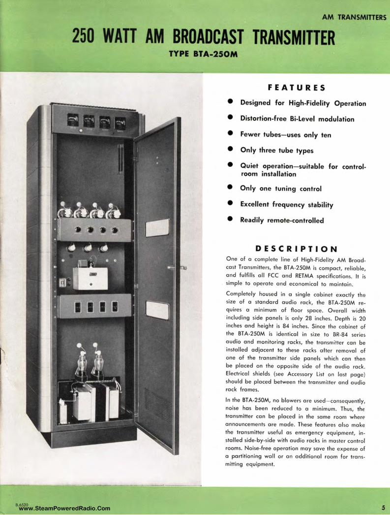
DESCRIPTION O ne of a complete line of High-Fidelity AM Broadcast Transmitters, the BT A-250M is compact, reliable, and fulfills all FCC and RETMA specifications. It is simple to operate and economical to maintain .
Completely housed in a single cabinet exactly the size of a standard audio rack, the BT A-250M requires a minimum of floor space. Overall width including side panels is only 28 inches. Depth is 20 inches and height is 84 inches. Since the cabinet of the BT A-250M is identical in size to BR-84 series audio and monitoring racks, the transm itter can be installed adjacent to these racks after removal of one of the transmitter side panels which can then be placed on the opposite side of the audio rack. Electrical shields (see Accessory List on last page) should be placed between the transmitte r and audio rack frames.
In the BTA-250M, no blowers are used- consequently, noise has been reduced to a minimum. Thus, the transmitter can be placed in the same room where announcements are made. These features also make the transmitter useful as emergency equipment, installed side-by-side with audio racks in master control rooms. Noise-free operation may save the expense of a partitioning wall or an additional room for transmitting equipment.
5 www.SteamPoweredRadio.Com
AM TRANSMITTERS
6
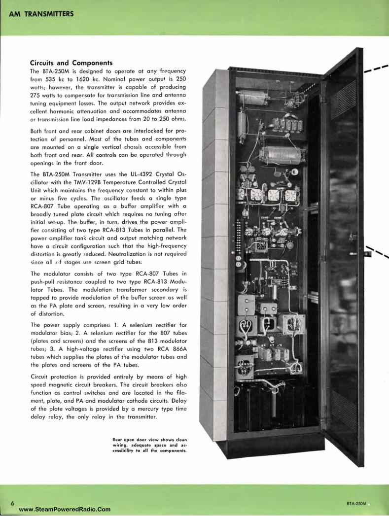
Circuits and Components The BT A-250M is designed to operate at any frequency
from 535 kc to 1620 kc. Nominal power output is 250
watts; however, the transmitter is capable of producing
275 watts to compensate for transmission line and antenna
tuning equipment losses. The output network provides ex
cellent harmonic attenuation and accommodates antenna
or transmission line load impedances from 20 to 250 ohms.
Both front and rear cabinet doors are interlocked for pro
tection of personnel. Most of the tubes and components
are mounted on a single vertical chassis accessible from
both front and rear. All controls can be operated through
openings in the front door.
The BT A-250M Transmitter uses the UL-4392 Crystal Os
cillator with the TMV-129B Temperature Controlled Crystal
Unit which maintains the frequency constant to within plus
or minus five cycles. The oscillator feeds a single type
RCA-807 Tube operating as a buffer amplifier with a
broadly tuned plate circuit which requires no tuning after
initial set-up. The buffer, in turn, drives the power ampli
fier consisting of two type RCA-813 Tubes in parallel. The
power amplifier tank circuit and output matching network
have a circuit configuration such that the high-frequency
distortion is greatly reduced. Neutralization is not required
since all r-f stages use screen grid tubes.
The modulator consists of two type RCA-807 Tubes in
push-pull resistance coupled to two type RCA-813 Modu
lator Tubes. The modulation transformer secondary is
tapped to provide modulation of the buffer screen as well
as the PA plate and screen, resulting in a very low order
of distortion.
The power supply comprises: 1. A selenium rectifier for
modulator bias; 2. A selenium rectifier for the 807 tubes
(plates and screens) and the screens of the 813 modulator
tubes; 3. A high-voltage rectifier using two RCA 866A
tubes which supplies the plates of the modulator tubes and
the plates and screens of the PA tubes.
Circuit protection is provided entirely by means of high
speed magnetic circuit breakers. The circuit breakers also
function as control switches and are located in the fila
ment, plate, and PA and modulator cathode circuits. Delay
of the plate voltages is provided by a merccry type time
delay relay, the only relay in the transmitter.
Rear open door view shows clean wiring, adequate space and ac• cessibility to all the components.
BTA-250M www.SteamPoweredRadio.Com
• A
BTA-250M
UL - 4 ~9Z OSCILLATOR
RC A 80 7
• A
Z RC A 807 FlRST AUDIO
AM TRANSMITTERS
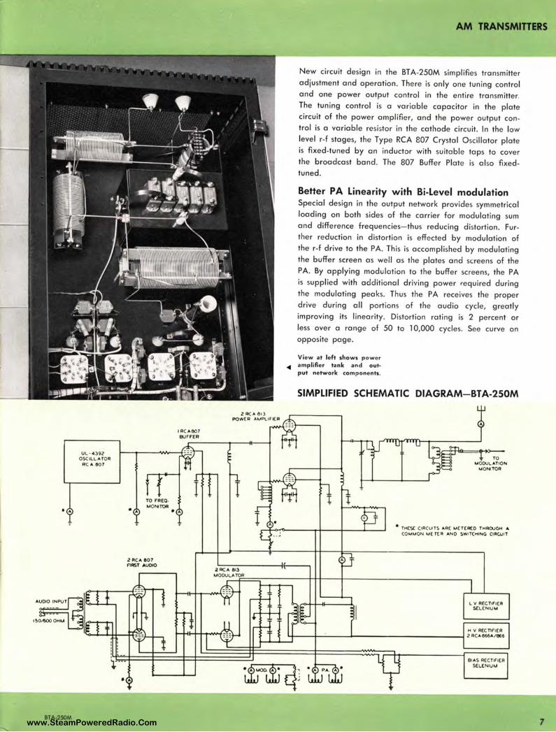
New circuit design in the BT A-250M simplifies transmitte r adjustment and ope ration . The re is only one tuning control and one power output control in the entire transmitte r. The tuning control is a variable capacitor in the plate circuit of the power amplifier, and the powe r output control is a variable resistor in the cathode circuit. In the low level r-f stages, the Type RCA 807 Crystal Oscillator plate is fixed -tuned by an inductor with suitable taps to cover the broadcast band. The 807 Buffe r Plate is al so fixed tuned .
Better PA Linearity with Bi-Level modulation Special design in the output network provides symmetrical loading on both sides of the carrier for modulat ing sum and difference frequencies- th us reducing distortion . Further reduction in distortion is effected by modulation of the r-f drive to the PA. This is accomplished by modulating the buffer screen as well a s the plates and screens of the PA. By applying modulation to the buffer sc reens, the PA is supplied with additional driving power required during the modulating peaks. Thus the PA receives the proper drive during all portions of the audio cycle, greatly improving its linearity. Distortion rating is 2 percent or less over a rang e of 50 to 10,000 cycles. See curve on opposite page.
View at left shows power • am pl ifier tank and o ut• put network co mpo nents.
SIMPLIFIED SCHEMATIC DIAGRAM- BTA-250M
A
• TH(S( CIACVTS ARC M(T(A(O THROJGH A co,.o.AON ~ETC A ANO SWITCHING CIAC.UIT
L V AEC T1F1[R SCL( NIU U
BIAS RECTIFIER SELENIU'-1
7 www.SteamPoweredRadio.Com
AM TRANSMITIERS
a
SPECIFICATIONS AF Input lmpedance ....... .... ........ ........ ................................... 150/ 600 ohms
AF Input Leve l (100% mod.) ................................................ + 10 ± 2 dbm
AF Response : 50•7,500 cycles ............................................................................ ± 1 db 30• 10,000 cycles ............ .. ....... .... ............................................... ± 1.5 db
AF Distortion (95 % mod .) 50· 10,000 cycles ............................ .............. 2%
Noise (below 100% mod.) .......... .. ............................. ..... ... ....... ...... - 60 db
Frequency Range ...... ......................... .......... .... ......................... 535• l 620 kc
Frequency Stability ................... ......... ..................... .... ....... ........ ± 5 cycles
Type of Output ... ........ ........................................................... .. Single ended
Carrier Shift (0•100% mod.) ............. ... ....... .................................. ..... 2½%
Output Impedance ..... ................... ........................ .......... ........ 20•250 ohms
R· F Voltage (for freq. monitoring) .. .............................. 10 v. RMS 75 ohms
R· F Voltage (for mod. monitoring ) ................................ 10 v. RMS 75 ohms
Power Output Capability ........ ....... ......... ............................. .... ..... 275 watts
Power Requirements ... ............... 110/ 125 volts, sing le phase, 50·60 cycles
Power Consumption: No Modulation ................................................. ........... 1000 w. approx. Average Program Modulation ............................. ......... 1150 w. approx. 100% Modulation ......... ....... .................................... .. .. 1400 w. approx.
Power Factor ................................... .......................................... ...... ..... 90%
Permissib le Combined Line Voltage Variation and Regulation ... ..... ± 5%
Buffer Tuning .... ......... ......................... ........... ..... ........................ Fixed tuned
PA Tuning .................................................... Air capacitor (with dust cover)
Number of Oscillators ........................... ........... ... ... ...... ................. ............. 1
Provisions for Spare Crystals ......................... ... .. ..... .......................... ......... 1
Number of Meters ............................................ ... ..... ....... ............................. 4
Circuits Metered .... ................ .. .. ................................................. .............. 13
Overload Circuits ................ Filaments, plates, PA cathode, mod. cathode
Cabinet Dimensions .................... Height 847/e", Width 28" , Depth 20½" (Less door handle)
Overall Height ............................... ..... ...... .... .... ............ ..... ........ ......... 86% "
Weight (unpacked) .............................. .............................. Approx. 600 lbs.
•2
+ I
t;,,-
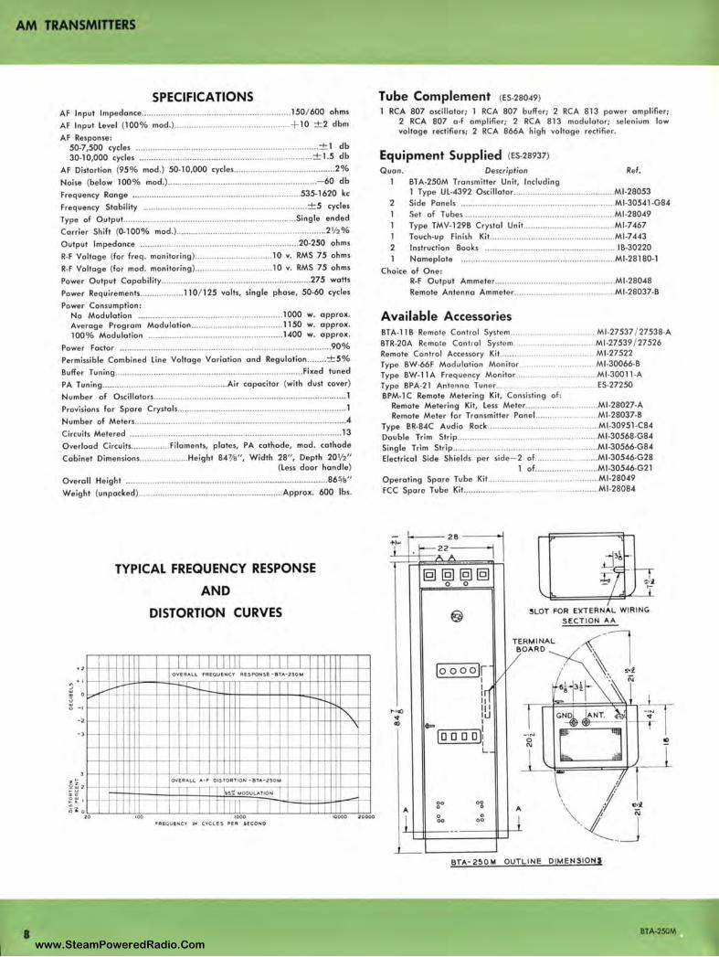
TYPICAL FREQUENCY RESPONSE
AND
DISTORTION CURVES
OVERALL FREQUENCY AESPON!E · 8TA·2SOM
............... ~r--,_ -;...
- --
·• ·•
1-- +-!-
I""--1--
t-
-0
20
·-·-t-t-
I-
-I-
·- -WJ~t-h OVERALL A· F 015TORT ION • 8TA·2!0M
Ill T l i.; ,-t " OOULATIO N ~
I 17 r1 '; rn - ,_ I 11
100 1000 l0000 20000 •A&.QUINCY IN CYCLES PEA 11!.COND
Tube Complement (Es.28049)
RCA 807 oscillator; 1 RCA 807 buffer; 2 RCA 813 power amplifier; 2 RCA 807 a •f amplifier; 2 RCA 813 modulator; se lenium low voltage rectifiers; 2 RCA 866A high voltage rectifier.
Equipment Supplied (ES.28937)
Quan . 1
2
1 2
Description Ref. B1A•250M Transmitter Unit, Including 1 Type UL.4392 Oscillator ................................ .......... Ml.28053 Side Pane ls ................ .. ..... .............. ........................... Ml •30541 •G84 Set of Tubes ..... ......................................................... MJ .28049 Type TMV•129B Crystal Un it... ................................... MJ .7467 Touch•up Finish Kit ........................................ ........... MJ .7443 Instruction Books ...................... ..... ........ ................... I 8•30220 Nameplate ................................ ...........•.................... Ml•28180· 1
Choice of One: R-F Output Ammeter .................................................. Ml -28048 Remote Antenna Ammeter ...... ............. .. ............... ..... Ml -28037-8
Available Accessories BTA-118 Remote Control System ...... BTR-20A Remote Control Syste m .. Remote Control Accessory Kit ......... . Type BW-66F Modulation Monitor. Type BW-1 lA Frequency Monitor Type BPA-21 Antenna Tuner .......... .
. ..... Ml -27537 / 27538-A . ..................... Ml-27539 / 27526
. ..... ...... ........... Ml -27522 . .... Ml-30066-8
...... . .............. Ml-30011 -A . ..... ES-27250
8PM-1 C Remote Metering Kit, Consisting of : Remote Metering Kit, Less Mete r ...... ................. ..... .. Ml -28027-A Remote Meter for Transmitter Panel. .................... Ml -28037-8
Type BR-84C Audio Rack ............................................. Ml -30951 -C84 Double Trim Strip ............... ............................. ... ........... Ml-30568-G84 Single Trim Strip ................................................. ........... Ml -30566-G84 Electrical Side Shields per side- 2 of ......................... Ml -30546-G28
1 of .. ... .. .. ................. Ml -30546•G21 Operating Spare Tube Kit ...... ... ................................... Ml -28049 FCC Spare Tube Kit...... ......... .. . . ....... .... . .. ............ Ml-28084
- 28 ·r -22 I ;;... ,._ -- --
1§1 @I @I 1§1 0 0
@
!oooolf I/
ln '"''° Iii .., li.J
'° ~ I
1° 0 0 0 1: I L_
00 og "
0
I 0 0 00 00
---'---
SLOT FOR ElCTERN,_L WIRING SECTION ,_,_
TE RMIN,_L O,_RD
I)
" l
_,,_. 0 N
1Ml ;;;
8T,.,-2~0M OUTLINE DIMENSIONS
BTA-250M
www.SteamPoweredRadio.Com
AM TRANSMITTERS
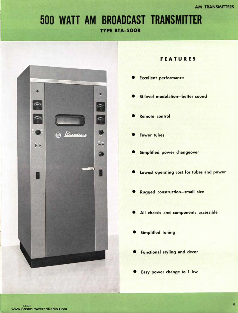
500 WATT AM BROADCAST TRANSMITTER TYPE BTA-500R
FEATURES
• Excellent performance
• Bi-level modulation- better sound
• Remote control
• Fewer tubes
• Simplified power changeove r
• Lowest operating cost for tubes and power
• Rugged construction- small size
• All chassis and components accessible
• Simplified tuning
• Functional styling and decor
• Easy power change to 1 kw
B.6504 9 www.SteamPoweredRadio.Com

AM TRANSMITIERS
USES Modern trends in AM radio broadcasting including excel lent performance, remote control and Conelrad requirements togethe r with all -around economy, dependability and new styling are featured in RCA's new Type BT A-500R AM Broadcast Transmitter. Simplified power change made possible by standardized circuitry is basic in the BT A-500R. Remote control provisions permit unattende d operation of the transmitter. Also included in the design, with the add ition of accessories, is remote Conelrad switching .
The BTA-500R AM Broadcast Transmitter is designed to ope rate on any frequency from 535 kc to 1620 kc with a normal rated output of 500 watts. The maximum transmitter output is 550 watts to compensate for transmission line and antenna tuning equipment losses. The transmitter will meet all requireme nts of the FCC and EIA pertaining to this class of equipment.
Improved functional design and novel decor which permits choice of color combinations to harmonize with studio color schemes are an important departure in RCA's new 500 watt transmitter. A single vertically-constructed cabinet houses the equipment. Square construction permits locating the transmitter against the wall, or it can be butted against other equipment. The vertical construction makes it accessible from both front and rear for ease of maintenance. Fewer tubes and tube types, reduced tube costs, and bi-level modulation; use of tetrodes with resultant elimination of neutralization; a single front panel tuning control providing easiest operation are other features of the BT A-500R.
The front of the BTA-S00R permits easy tube changes. The power amplifier and modu lator tubes are located on the top chassis and just below this is the exciter chassis. All normal operating controls are
shown on the two side panels.
DESCRIPTION
10
The Type BTA-500R Transmitter is designed to provide an amplitude modulated signal at any frequency in the standard broadcast band between 535 kc and 1620 kc. The nominal power output rating is 500 watts and maximum output capability 550 watts. The transmitter will operate from a 208-240 volt, 60 cycle, single phase power source for the main power. A 50 cycle kit is available. In addition the crystal heaters require an additional 115 volt, 50/ 60 cycle, a -c power input.
The entire transmitter is housed in a single aluminized steel cabinet. The cabinet consists of two end panels with the fronts formed to provide control panels mounted on a sturdy welded steel base. Vertical center chassis are fastened between the end panels to form a basic H cross section. A hinged front door is located between the two control panels . Rear access is provided by two interlocked removable panels. Control components are conveniently located on the control panels on both sides of the front door and all meters are at eye level.
Most BT A-500R components are mounted on a vertical center chassis which provides extremely good accessibility. Tubes, feedback ladders and overload relays are mounted on the front and the other components are mounted on the rear of this chassis. Larger power components are mounted on the base.
The BT A-500R has been designed around standardized circuits. Included in the basic transmitter is an exciter unit, low voltage supply, bias supply and a portion of the control circuits. By adding to the exciter unit the proper r-f, modulator, high voltage rectifier and power determining components either a 500 watt or l 000 watt transmitter can be provided.
New design techniques utilized in the BT A-500R provide simplified tuning, reduced installation time and expense. Tetrodes are utilized throughout the r-f section to eliminate the requirement for neutralization. Another feature is the very successful RCA bi-level modulation system which contributes to the soundability of the transmitter. A new RCA
BTA-500R
www.SteamPoweredRadio.Com
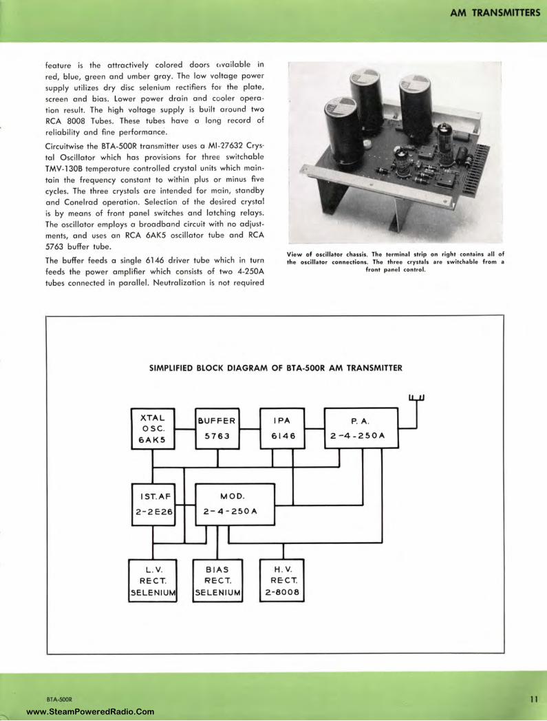
feature is the attractively calored doors c,vailable in
red, blue, green and umber gray. The low voltage power
supp ly utilizes dry disc selenium rectifiers for the plate ,
screen and bias. Lower power drain and cooler opera
tion result. The high vo ltage supply is built around two
RCA 8008 Tu bes. These tubes have a long record of
reliability and fine performance.
Circuitwise the BT A-500R transmitter uses a Ml-'27632 Crys·
tal O scillator which has provisions for three switchable
TMV- 130B temperature controlled crystal units which main
tain the frequency constant to within plus or minus five
cycles. The three crystals are intended for mai n, standby
and Conelrad operation. Selection of the desired crystal
is by means of front panel switches and latching relays.
The oscillator employs a broadband circuit with no adjust
ments, and uses an RCA 6AK5 oscillator tube and RCA
5763 buffer tube.
The buffer feeds a single 6146 driver tube which in turn
feeds the power amplifier which consists of two 4-250A
tubes connected in parallel. Neutralization is not required
AM TRANSMITTERS
View of oscillator chassis. The terminal strip on right contains all of the osci llator co nnections. The three crystals are switchable from a
fro nt pa ne l co ntrol.
SIMPLIFIED BLOCK DIAGRAM OF BT A-S00R AM TRANSMITTER
XTAL &UFFER IPA P. A . osc. - - - ----
6AK5 5763 6146 2-4-250A
l
I ST.AF MOD. --2 - 2E26 2-4 - 250A
I I I
L . V. B IAS H. V.
RECT. R ECT. RECT.
SELEN IUM SE L EN IUM 2-8008
BTA-500R 11 www.SteamPoweredRadio.Com
AM TRANSMITTERS
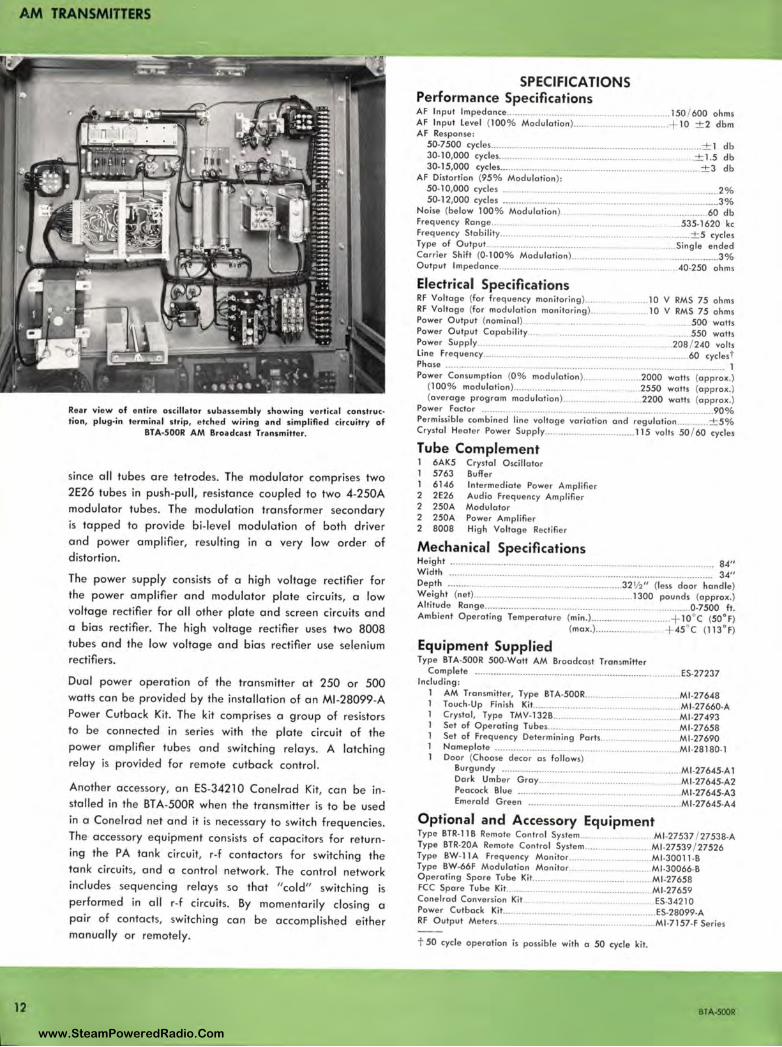
12
Rear view of entire oscillator subassembly showing vertical construe• tion, plug•in terminal strip, etched wiring and simplified circuitry of
BTA•S00R AM Broadcast Transmitter.
since all tubes are tetrodes. The modulator comprises two 2E26 tubes in push-pull, resistance coupled to two 4-250A modulator tubes. The modulation transformer secondary is tapped to provide bi-level modulation of both drive r and power amplifier, resulting in a very low order of distortion.
The power supply consists of a high voltage rectifier for the power amplifier and modulator plate circuits, a low voltage rectifier for all other plate and screen circuits and a bias rectifier. The high voltage rectifier uses two 8008 tubes and the low voltage and bias rectifier use selenium rectifiers.
Dual power ope ration of the transmitter at 250 or 500 watts can be provided by the installation of an Ml -28099-A Power Cutback Kit. The kit comprises a group of resistors to be connected in se ries with the plate circuit of the power amplifier tubes and switch ing relays. A latch ing relay is provided for remote cutback control.
Another accessory, an ES-34210 Cone lrad Kit, can be insta lled in the BTA-500R whe n the transmitter is to be used in a Conel rad ne t and it is necessary to switch frequenci es. The accessory equipment consists of capacitors for return ing the PA tank circuit, r-f contactors for switching the tank circuits, and a control network . The control network includes seque ncing rel ays so that "cold" switching is performed in all r-f circuits. By mome ntarily closing a pa ir of contacts, switching can be accompl is hed either manually or remotely.
SPECIFICATIONS Performance Specifications AF In put Impedance........ .. .......... ........ .... .... ... . ......... 150 / 600 ohms AF Input Level (100% Modulation ) ................................... + 10 ± 2 dbm AF Response :
50•7500 cycles .... .. .......... ... .. ...................................................... ... ± 1 db 30• 10,000 cycles ................................................................ ...... ± 1.5 db 30.15,000 cycles .... ........ ............. .. ................................................. ± 3 db
AF Distortion (95% Modulation ): 50• l 0,000 cycles ... ..... ... . .. .............. . ................ ........ .. ........ 2% 50.12,000 cycles .......... .............. ................... ....................................... 3 %
Noise (below 100% Modulation) ..... .. . .. ... ... . ..... ...... 60 db Frequency Range.......... ....... •........... . 535• 1620 kc Frequency Stability.. .. ..... ± 5 cycles Type of Outpu t..... ............................................. Single ended Carrier Shift (0• 100% Modulation).. .. ........... .. ........... .. . ..... ... ..... .... 3% Output Impedance............. . ....... .. . .... -40•250 ohms
Electrical Specifications RF Voltage (for frequency monitoring ).... . .... 10 V RMS 75 ohms RF Voltage (for modulation monitoring ). ... . .. 10 V RMS 75 ohms Power Output (nominal ). .... ... .... ....... .. . .... 500 walls Power Output Capability.... . .... ................ ........ . ....... 550 walls Power Supply ............ .... .... . ........ 208 / 2-40 volts Lin e Frequency.. .. .. ............................... ............ . . ... 60 cyclest Phase ........................... ...... ...................... .................... ..................... 1 Power Consumption (0 % modulation )... 2000 walls (approx.)
(100% modulation)............ .... .. ... .... . .............. 2550 walls (approx.) (average program modulation )..... .. .......... 2200 walls (approx .)
Power Factor ....................................................................... ... .............. 90% Permissible combined line voltage variation and regu lation ............ ± 5% Crystal Heater Power Supply ..................... ........... 115 volts 50 / 60 cycles
Tube Complement 1 6AK5 Crystal Oscillator 1 5763 Buffer 1 61 -4 6 Intermediate Power Amplifier 2 2E26 Audio Frequency Amplifier 2 250A Modulator 2 250A Power Amplifi er 2 8008 High Voltage Rectifier
Mechanical Specifications Height ................................................................................................. 84" Width ................. ................................................................. ............. ... 3-4" Depth ........ ....................................................... 32 ½ " (less door handle) Weight (net) ..................... .. ........................ .... .... .. 1300 pounds (approx.) Alti tude Range ........... ....... ... ............ ..... ... .................................... 0•7500 ft. Ambient Operating Temperature (min.) .......... ... ........ ...... ... + 10°C (50°F)
(max.) ................... .. .... + 45°C (113° F)
Equipment Supplied Type BTA·500R 500.Watt AM Broadcast Tran,miller
Complete .............................. .................. ..... ... .... .................. ES.27237 Including :
1 AM Transmitter, Type BTA·500R .............................. .... Ml .27648 Touch•Up Finish Kit .. ....... .. ......................................... Ml .27660·A Crystal, Type TMV. 132B ............................................ Ml.27-493 Set of Operating Tubes.. ............................ .......... ... Ml .27658 Set of Frequency Determining Pa ris ....................... Ml .27690 Nameplate ... .. ....... .. .. ........ ................................. ........ Ml•28180•1 Door (Choose decor as follows)
Burgundy ................ ......... ............................. ..... ..... M1 •276-45•A 1 Dark Umber Gray........... ............................ . .......... Ml •276-45•A2 Peacock Blue .............. ................ .... ....... . ..... Ml •27645•A3 Emerald Green .......................................................... M1 •276-45•A4
Optional and Accessory Equipment Type BTR· 11 B Remote Control System Ml .27537 / 27538.A Type BTR.20A Remote Control System .. ...................... Ml .27539 / 27526 Type BW.11 A Frequency Monitor ...................... . .... .. Ml .30011 ·B Type BW.66F Modulation Monitor .................. ...... ... Ml.30066.B Operating Spore Tube Kit. ........................ .. ................ Ml .27658 FCC Spare Tube Kit .................... .............. ................... Ml •27659 Cone lrad Conversion Kit .. .. ... ES.3-4210 Power Cutback Kit... ................................ .. ................ ES.28099.A RF Output Meters.. ..................... .................................. Ml •7157•F Series
t 50 cycle operation is possib le with a 50 cycle kit.
BTA·SOOR
www.SteamPoweredRadio.Com
wigfi
Stolen 2 Line Transparent
AM TRANSMITTERS
1 KW AM BROADCAST TRANSMITTER TYPE BTA-lR
FEATURES
• Lowest operating cost for tubes and power
• Simple to operate- only one tuning control
• Bi-level modulation provides finest sound
• No neutralization
• Remote control provisions for main, stand-by or Conelrad switching
• Fewer tubes- fewer tube types
• Simplified power changeover
• Functional styling and decor
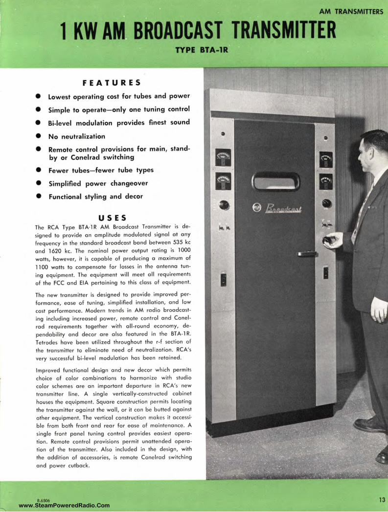
USES The RCA Type BTA-1 R AM Broadcast Transmitter is de
signed to provide an amplitude modulated signal at any
frequency in the standard broadcast band between 535 kc
and 1620 kc . The nominal power output rating is 1000
watts, however, it is capable of producing a maximum of
1100 watts to compensate for losses in the antenna tun
ing equipment. The equipment will meet all requirements
of the FCC and EIA pertaining to this class of equipment.
The new transmitter is designed to provide improved per
formance, ease of tuning, simplified installation, and low
cost performance. Modern trends in AM radio broadcast
ing including increased power, remote control and Conel
rad requirements together with all-round economy, de
pendability and decor are also featured in the BT A-1 R.
T etrodes have been utilized throughout the r-f section of
the transmitter to eliminate need of neutralization. RCA's
very successful bi-level modulation has been retained.
Improved functional design and new decor which permits
choice of color combinations to harmonize with studio
color schemes are an important departure in RCA's new
transmitter line. A single vertically-constructed cabinet
houses the equipment. Square construction permits locating
the transmitter against the wall, or it can be butted against
other equipment. The vertical construction makes it accessi
ble from both front and rear for ease of maintenance. A
single front panel tuning control provides easiest opera
tion. Remote control provisions permit unattended opera
tion of the transmitter. Also included in the design, with
the addition of accessories, is remote Conelrad switching
and power cutback.
8.6506 13 www.SteamPoweredRadio.Com

AM TRANSMITIERS
14
BTA-lR Transmitter with front door open showing accessibility of tubes and com• ponents. Power Amplifier and Modulator tubes are shown on top chassis; below is exciter chassis. All normal operating con• tacts are shown on two side panels.
DESCRIPTION
I
The Type BTA-1 R Transmitter is designed to provide an amplitude modulated signal at any frequency in the standard broadcast band between 535 kc and 1620 kc. The nominal power output rating is 1000 watts and maximum output capability 1100 watts. The transmitter will operate from a 208-240 volt, 60 cycle, single phase power source for the main power. In addition the crystal heaters require an additional 115 volt, 50/ 60 cycle, a-c power input. The Transmitter can be modified for operation on 50 cycle a -c current if desired .
The entire transmitter is housed in a single aluminized steel cabinet. The cabinet consists of two end panels with the fronts formed to provide control panels mounted on a sturdy welded steel base. Vertical center chassis are fastened between the end panels to form a basic H-cross section. A hinged front door is located between the two control panels . Rear access is provided by two interlocked
View of oscilla tor chassis. The terminal strip on right contains all of the oscillator connec tions. The three crystals are switchable from a
front panel control.
BTA-IR
www.SteamPoweredRadio.Com
AM TRANSMITTERS
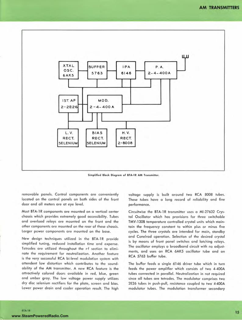
u,.u
X T A L BUFF-ER IPA P. A . osc . - - - -6AK5
5763 6146 2-4 - 400A
I
! ST. AF MOD. --2 - 2E-26 2 - 4 - 400A
I I I
L. V. BIAS H. V.
RECT. RECT. RECT. SELEN IUM SELEN IUM 2 - 8008
Simplified Block Diagram of BTA-1 R AM Tra nsmitter.
removable panels. Control components are conveniently located on the control panels on both sides of the front door and all meters are at eye level.
Most BT A-1 R components are mounted on a vertical center chassis which provides extremely good accessibility. Tubes and overload relays are mounted on the front and the other components are mounted on the rear of these chassis. Larger power components are mounted on the base.
New design techniques utilized in the BT A-1 R provide simplified tuning , red uced installation time and expense. Tetrodes are utilized throughout the r·f section to elimi
nate the requirement for neutralization. Another feature is the very successful RCA bi-level modulation syste m with attendent low distortion which contributes to the soundability of the AM transmitter. A new RCA feature is the attractively colored doors available in red, blue, green and umber gray. The low voltage power supply utilizes dry disc selenium rectifiers for the plate, screen and bias. Lower power drain and cooler operation result. The high
BTA-IR
voltage supply is built around two RCA 8008 tubes. These tubes have a long record of reliability and fine performance.
Circuitwise the BTA-1 R transmitter uses a Ml -27632 Crystal O scillator which has provisions for three switchable TMV-l 30B temperature controlled crystal units which maintain the frequency constant to within plus or minus five cycles. The three crystals are intended for main, standby and Conelrad operation. Selection of the desired crystal is by means of front panel switches and latching relays. The oscillator employs a broadband circuit with no adjustments, and uses an RCA 6AK5 oscillator tube and an RCA 5763 buffer tube.
The buffer feeds a single 6146 driver tube which in turn feeds the power amplifier which consists of two 4-400A tubes connected in parallel. Neutralization in not required since all tubes are tetrodes. The modulator comprises two 2E26 tubes in push-pull, resistance coupled to two · 4·400A
modulator tubes. The modulation transformer secondary
15 www.SteamPoweredRadio.Com
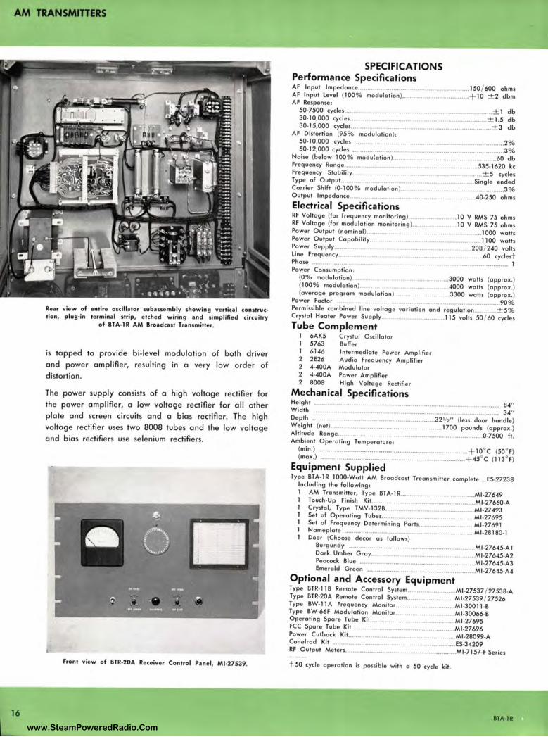
AM TRANSMITTERS
16
Rear view of entire oscillator subassembly showing vertical construe• lion, plug•in terminal strip, etched wiring and simplified circuitry
of BTA•l R AM Broadcast Transmitter.
is tapped to provide bi. level modulation of both driver and power amplifier, resulting in a very low order of distortion.
The power supply consists of a high voltage rectifier for the power amplifier, a low voltage rectifier for all other plate and screen circuits and a bias rectifier. The high voltage rectifier uses two 8008 tubes and the low voltage and bias rectifiers use selenium rectifiers.
Front view of BTR·20A Receiver Control Panel, Ml•27539.
SPECIFICATIONS Performance Specifications AF Input Impedance ......................................................... .. 150 / 600 ohms AF Input Level (100% modulation) .......... .................... ...... + 10 ± 2 dbm AF Response :
50•7500 cycles ................................................................................ ± 1 db 30.10,000 cycles ..................................................................... ± 1.5 db 30.15,000 cycles ............................................................................ ± 3 db
AF Distortion (95 % modulation ): 50• 10,000 cycles .. ........ ............................................................... ....... 2% 50• 12,000 cycles .............................................................................. .... 3%
Noise (below 100% modu lation) ..................................................... 60 db Frequency Range ...................................................................... 535· 1620 kc Frequency Stability..... .. .. ..................................................... ± 5 cycles Type of Output.. ...... .. .................................................... Single ended Carrier Shift (0·100% modulation ) .................................................... . 3% Output Impedance............................ .. .. ............................ 40.250 ohms
Electrical Specifications RF Voltage (for frequency monitoring )..... .. .............. .10 V RMS 75 ohms RF Voltage (for modulation monitoring ) .................... 10 V RMS 75 ohms Power Output (nominal ).............. .... .. ............................ 1000 watts Power Output Capability.. . ............................................ 1100 watts Power Supply................ .... . .... . ... ........ ............. ... ...208 / 240 volts Line Frequency........ .. ............................... 60 cyclest Phase .................. .. ............................................... 1 Power Consumption :
(0% modulation )..... ....... .. ............. 3000 watts (approx .) (100% modulation )....... .. ................ 4000 watts (approx. ) (average program modulation ) ... .. .. ... .. ........ 3300 watts (approx .)
Power factor .................... . .. .. ....................................... 90% Permissible combined line voltage variation and regu lation ............ ± 5% Crystal Heater Power Supply. .. ............... 115 volts 50 / 60 cycles Tube Complement
1 6AK5 Crystal Oscillator 5763 Buffer 6146 Intermediate Power Amplifier
2 2E26 Audio Frequency Amplifier 2 4•400A Modulator 2 4•400A Power Amplifier 2 8008 High Voltage Rectifier
Mechanical Specifications Heig ht .............................................................................................. ...... 84" Width .................................................................................................. 34" Depth ................................................................ 32½" (less door handle) Weight (net) ......................................................... 1700 pounds (approx.) Altitude Range .............................................................................. 0.7500 ft . Ambient Operating Temperature:
(min .) ...................................... .......................................... + 10°c (50 ° F) (max.) .............................................................................. + 45 °C (113° F)
Equipment Supplied Type BTA·lR lOOO•Watt AM Broadcast Treansmitter complete .... ES.27238
Including the following: 1 AM Transmitter, Type BTA-1 R ....................................... Ml•27649
Touch-Up Finish Kit ........................................................ Ml -27660·A Crystal, Type TMV-132B ................................................ Ml-27493 Set of Operating Tubes.. ............................................... Ml -27695 Set of Frequency Determining Parts.. ........................... Ml-27691 Nameplate ..................................................................... Ml•28180· 1 Door (Choose decor as follows)
Burgundy ................... ................................................. Ml •27645•A 1 Dark Umber Gray.. .. .......................................... Ml •27645•A2 Peacock Blue ............................................................. Ml -27645-A3 Emerald Green ............................................ .............. Ml -27645-A4
Optional and Accessory Equipment Type BTR• 11 B Remote Control System ....................... Ml•27537 / 27538.A Type BTR-20A Remote Control System .......................... Ml•27539 / 27526 Type BW-11 A Frequency Monitor ................................ Ml -30011 ·B Type BW•66F Modulation Monitor .............................. Ml .30066·B Operating Spare Tube Kit... ........................................... Ml -27695 FCC Spare Tube Kit ............................ ......... - ................ Ml -27696 Power Cutback Kit .......................................................... Ml -28099-A Conelrad Kit .............................................................. ES.34209 RF Output Meters ........................................................... Ml -7157-F Series
t 50 cycle operation is possible with a 50 cycle kit.
BTA•lR www.SteamPoweredRadio.Com
B.6508
AM TRANSMITTERS
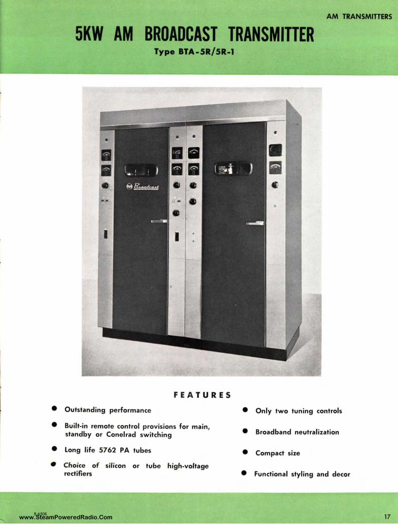
5KW AM BROADCAST TRANSMITTER Type BTA-5R/5R-1
FEATURES
• Outstanding performance
• Built-in remote control provisions for main, standby or Conelrad switching
• Long life 5762 PA tubes
• Choice of silicon or tube high-voltage rectifiers
• Only two tuning controls
• Broadband neutralization
• Compact size
• Functional styling and decor
17 www.SteamPoweredRadio.Com
AM TRANSMITTERS
18
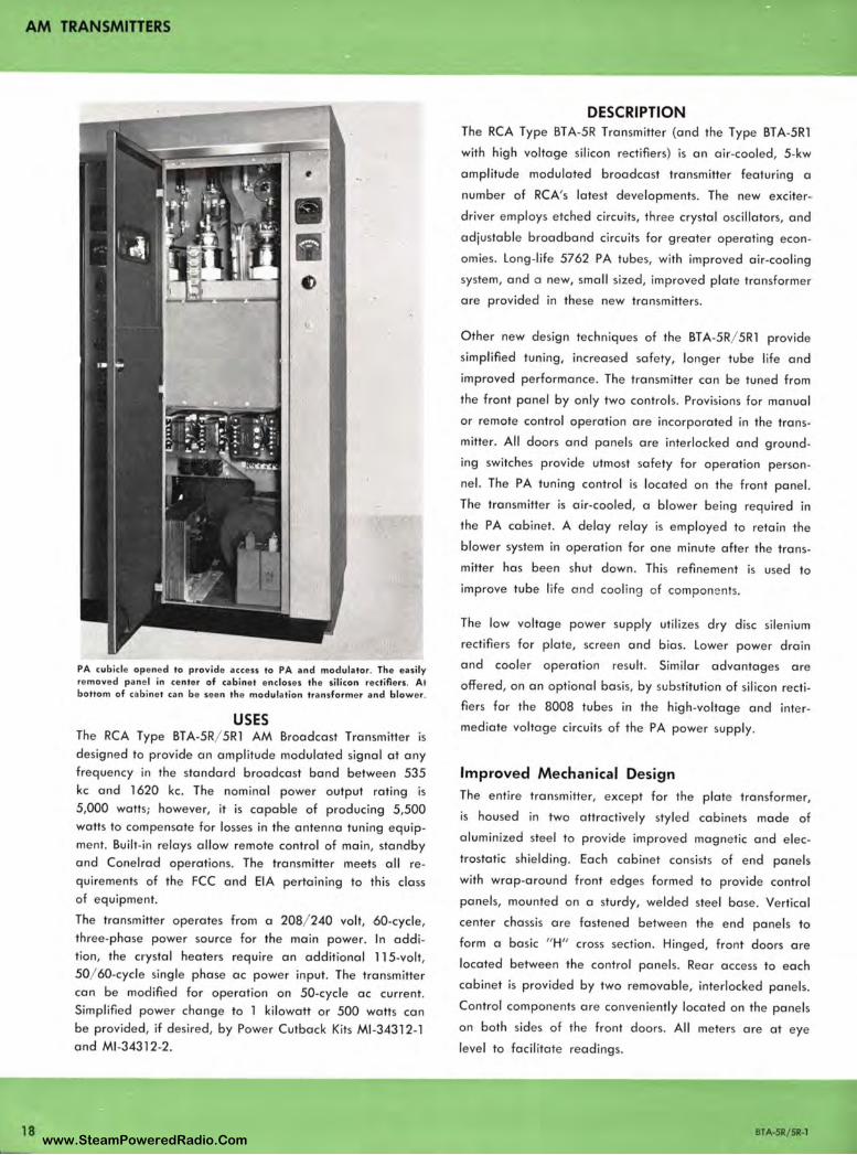
PA cubicle opened to provide access to PA and modula tor. The easily removed pane l in center of cabinet encloses the silicon rectifiers. At bottom of cabinet can be seen the modulation transformer and blower.
USES The RCA Type BTA-5R/ 5R1 AM Broadcast Transmitter is designed to provide an amplitude modulated signal at any frequency in the standard broadcast band between 535 kc and 1620 kc. The nominal power output rating is 5,000 watts; however, it is capable of producing 5,500 watts to compensate for losses in the antenna tuning equipment. Built-in relays allow remote control of main, standby and Conelrad operations. The transmitter meets all requirements of the FCC and EIA pertaining to this class of equipment.
The transmitter operates from a 208/ 240 volt, 60-cycle, three-phase power source for the main power. In addition, the crystal heaters require an additional 115-volt, 50/ 60-cycle single phase ac power input. The transmitter can be modified for operation on 50-cycle ac current. Simplified power change to 1 kilowatt or 500 watts can be provided, if desired, by Power Cutback Kits Ml -34312-1 and Ml -34312-2.
DESCRIPTION The RCA Type BTA-5R Transmitter (and the Type BTA-5R1
with high voltage silicon rectifiers) is an air-cooled, 5-kw
amplitude modulated broadcast transmitter featuring a
number of RCA's latest developments. The new exciter
driver employs etched circuits, three crystal oscillators, and
adjustable broadband circuits for greater operating econ
omies. Long-life 5762 PA tubes, with improved air-cooling
system, and a new, small sized, improved plate transformer
are provided in these new transmitters .
Other new design techniques of the BT A-5R/ 5R1 provide
simplified tuning, increased safety, longer tube life and
improved performance. The transmitter can be tuned from
the front panel by only two controls. Provisions for manual
or remote control operation are incorporated in the trans
mitter. All doors and panels are interlocked and ground
ing switches provide utmost safety for operation person
nel. The PA tuning control is located on the front panel.
The transmitter is air-cooled, a blower being required in
the PA cabinet. A delay relay is employed to retain the
blower system in operation for one minute after the trans
mitter has been shut down . This refinement is used to
improve tube life and cooling of compone nts.
The low voltage power supply utilizes dry disc silenium
rectifiers for plate, screen and bias . Lower power drain
and coole r operation result. Similar advantages are
offered, on an optional basis, by substitution of silicon recti
fiers for the 8008 tubes in the high -voltage and inte r
mediate voltage circuits of the PA power supply.
Improved Mechanical Design The entire transmitter, except for the plate transformer,
is housed in two attractively styled cabinets made of
aluminized steel to provide improved magnetic and elec
trostatic shielding . Each cabinet consists of end panels
with wrap-around front edges formed to provide control
panels, mounted on a sturdy, welded steel base. Vertical
center chassis are fastened between the end panels to
form a basic " H" cross section. Hinged, front doors are
located between the control panels. Rear access to each
cabinet is provided by two removable, interlocked panels.
Control components are conveniently located on the panels
on both sides of the front doors. All meters are at eye
level to facilitate readings.
8TA-5R/ 5R-1 www.SteamPoweredRadio.Com
The matched cabinets ore designed to combine on attrac
tive appearance with the utmost in utility. Doors ore
offered in burgundy red, peacock blue, emerald green
and dork umber gray, to harmonize with station surround
ings. Vertical construction permits easier maintenance and
service. It also permits installation of the transmitter against
a wall, and allows other equipment to be placed on either
side of the cabinet.
The front doors of the transmitter give immediate access
to the front of the vertical panels on which circuit com
ponents such as tubes, feedback ladders and overload
relays ore mounted. Remaining components are mounted
on the rear of these chassis, while the larger power com
ponents are situated in the base of the cabinet. This type
of construction provides excellent accessibility.
The left hand cabinet contains the BT A-5R exciter-driver,
while the right hand cabinet houses the amplifier, modu
lator and high voltage rectifier portions of the transmitter.
The cabinets require less than 16 square feet of floor space.
A plate transformer occupies only an additional 3 sq . ft .
Latest Radio and Audio Frequency Circuit Design The BT A-5R/ 5Rl Transmitter incorporates RCA's new
Ml -27632 Crystal Oscillator with three, switchable, tem
perature-controlled crystal units . Each crystal will remain
constant within plus or minus five cycles. The three crystals
control main, standby and Conelrad operation. The de-
New Crystal Oscillator, Ml-27632, showing three, swit chab le tempera• lure-controlled crystal units for controlling transmitter main, standby
and Conelrad operations.
BTA-SR; SR-1
AM TRANSMITTERS
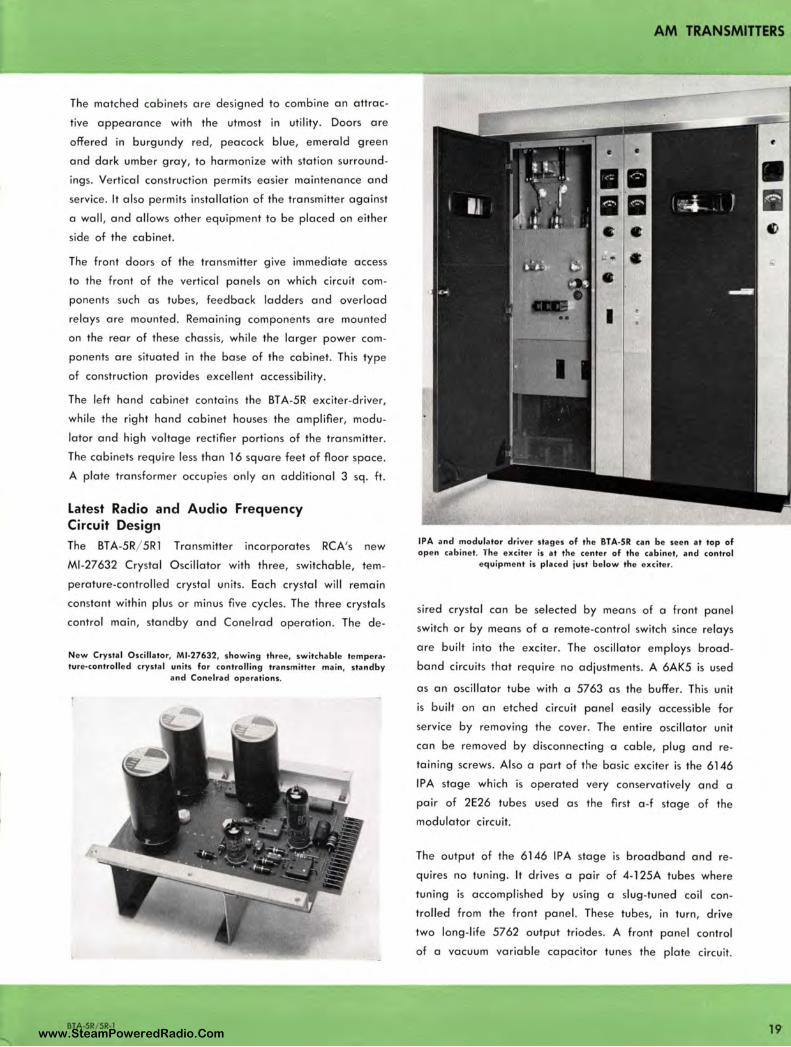
IPA and modulator driver stages of the BTA-SR can be seen at top of open cabinet. The exciter is at the center of the cabinet, and control
equipment is placed just below the exciter.
sired crystal can be selected by means of a front panel
switch or by means of a remote-control switch since relays
are built into the exciter. The oscillator employs broad
band circuits that require no adjustments. A 6AK5 is used
as an oscillator tube with a 5763 as the buffer. This unit
is built on an etched circuit panel easily accessible for
service by removing the cover. The entire oscillator unit
can be removed by disconnecting a cable, plug and re
taining screws. Also a part of the basic exciter is the 6146
IPA stage which is operated very conservatively and a
pair of 2E26 tubes used as the first a -f stage of the
modulator circuit.
The output of the 6146 IPA stage is broadband and re
quires no tuning . It drives a pair of 4-125A tubes where
tuning is accomplished by using a slug-tuned coil con
trolled from the front panel. These tubes, in turn, drive
two long-life 5762 output triodes. A front panel control
of a vacuum variable capacitor tunes the plate circuit.
19 www.SteamPoweredRadio.Com

AM TRANSMITTERS
20
Silicon rectifier chauis of the BTA-5R1 Transmitter showing two banks of thirty silicon cells which comprise the full-wave rectifier. Silicons offer improved performance since they are particularly resistant to
aging, moisture, and wide temperature variations.
A new slug-tuned coil was developed for the power
output adjustment and it is driven by a reversible motor.
The motor is actuated at the front panel or by a remote
power output adjustment switch. The second harmonic
trap uses a slug-tuned coil, thus eliminating the possibility
of contact pitting from high current in the r-f circuit of
the transmitter. Neutralization of the 5762 PA stage is
achieved by broadband transformers and a variable
vacuum capacitor. The use of a broadband type of trans
former holds neutralization over a wide band and pre
vents spurious oscillation at other frequencies .
The modulator of the transmitter consists of a pair of 2E26
tubes located in the exciter portion, resistance coupled
to drive a pair of ,6155/ 4-l 25A second audio frequency
amplifiers which, in turn, are resistance coupled to drive a
pair of 3X3000Fl modulators . These modulator tubes are
low mu triodes, drawing no grid current. They are capable
of excellent response and fidelity.
Dependable Semiconductor Power Supply The BTA-5R normally is supplied with Type 8008 RCA
Tubes for the high-voltage rectifier. However, in keeping,
with the latest trend to improve products, another version
of the transmitter has been deve loped- the Type BTA-5 Rl ,
which incorporates silicon-type rectifiers in the high-voltage
circuits . This rectifier is ideal not only in a combined opera
tion, but even more so in a remote-control application.
The rectifiers are hermetically sealed so they will not be
adversely affected by weather conditions. They can oper
ate at ambient temperatures ranging from - 20°C to
+ 45 °C and at altitudes up to 7500 feet above sea level.
There is no significant aging of the forward drop char
acteristics. Across each one of the silicon cells a resistor
has been shunted so that they will all share equally the
peak inverse voltage rating. RCA specifications have been
set higher than EIA standards by adding an additional
30 percent peak inverse voltage safety factor.
New motor-driven, slug-tuned power-output coil shown at upper right. The tuning control is on the front panel.
\ .•.
BTA-SR/ SR-1 www.SteamPoweredRadio.Com
wigfi
Stolen 2 Line Transparent
Cooling System The transmitter is completely air-cooled. Added refinements
such as a delay relay have been built-in to keep the
blower system in operation for one minute after the trans
mitter has been shut down. The continued supply of air
extends tube life. The exciter cabinet employs air con
vection cooling. A louvered lower back panel and top
grill pane l provide good ventilation. In the second cabinet
a blower air system distributes air to the modulator and
PA tubes. The forced air is also used to cool the PA tank
circuit. Rectifie r tubes in the BT A-5R are cooled by a
sma ll, the rmally-controlled blower, that is not required
with dry-disc silicon rectifiers in the BT A-5Rl. When silicon,
high-voltage rectifiers are installed, air from the main
blower is utilized, assuring an additional safety factor.
Close up view of the exciter with two crystal units in p lace , Just above the crystals is the 6146 r-f driver. To the left may be noted the pair of 2E26 tubes for the a-f input. Panel below exciter is removed to
show circuit breakers and fuses.
•
I
BTA-SR/ 5R-1
AM TRANSMITTERS
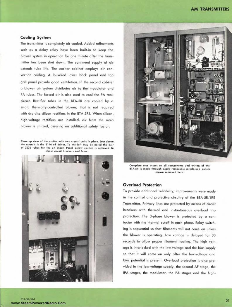
Co mplete rear access to all components and wiring of the BTA-SR is made th rough easily removable interlocked panels
shown removed here .
Overload Protection
To provide add itional reliability, improvements were made
in the control and protective circuitry of the BTA-5R/ 5Rl
Transmitter. Primary lines are protected by means of circuit
breakers with thermal and instantaneous overload trip
protection. The 3-phase blower is protected by a con
tactor with the thermal cutoff in each phase. Relay switch
ing is sequential so that filaments will not come on unless
the blower is operating. Low voltage is delayed for 30
seconds to allow proper filament heating. The high volt
age is interlocked with the low-voltage and the bias supply
so that it will come on only after the low-voltage and
bias potential is present. O verload protection is also pro
vided in the low-voltage supply, the second AF stage, the
IPA stages, the modulator, the PA stages and the high -
21 www.SteamPoweredRadio.Com
AM TRANSMITTERS
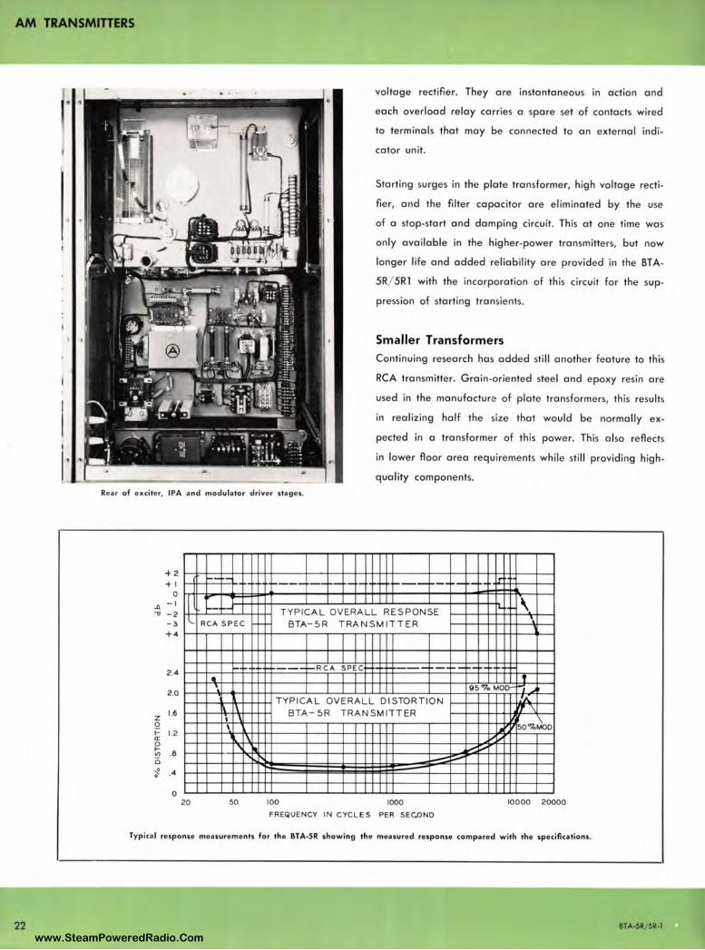
22
voltage rectifier. They ore instantaneous in action and
each overload relay carries a spare set of contacts wired
to terminals that may be connected to an external indi
cator unit.
Starting surges in the plate transformer, high voltage recti
fier, and the filter capacitor ore elimina ted by the use
of a stop-start and damping circuit. This at one time was
only available in the higher-power transmitters, but now
longer life and added re liability ore provided in the BT A-
5R/ 5Rl with the incorporation of this circuit for the sup
pression of starting transients.
Smaller Transformers
Continuing research has added still another feat ure to this
RCA transmitter. Grain-oriented steel and epoxy resin ore
used in the manufocture of plate transformers, this results
in realizing half the size that would be normally ex
pected in a transformer of this power. This also reflects
in lower floor area requirements while sti ll providing high
quality components. Rea r of exci ter, IPA and modulator driver stages.
+2
+1 ,..._ ~- 1-- .• l!
.,_ ___ -- ,.._ ·-,--- ·-0
..Q. -I
-cs -2 -:,
I \ -- -- TYPICAL OVERALL RESPONSE ,-l RCA SPEC BTA- 5R TRANSMITTER ·,
+4
2.4 -· --- - RCA SPEC ,...,. --- - ---- •-•
2 .0 ·, 95°lo MOir ,,..
TYPICAL OVERALL DISTORTION A.
z 1.6
Q t- 1.2 a: ~
.8 VJ Q
\ \ BTA - 5R TRAN SM ITT ER ,, \
I ,
50%~0 \ .. I \ ~--' Ill V- i, ... r-, ---~ . .4
0 20 50 100 1000 10000 20000
FREQUENCY IN CYCLES PER SEC.ONO
Typical response measurements for the BTA-S R showing the measured response compared with the specifications.
BTA-SR / SR-1
www.SteamPoweredRadio.Com
"' .... )>
.:,,
!" "' ~ ..., w
AU
DIO
1N
PV
T
CR
YS
TA
L S
EL
EC
TO
R
I
a:
w
N *
I R
C,,
6
AK
5
I I
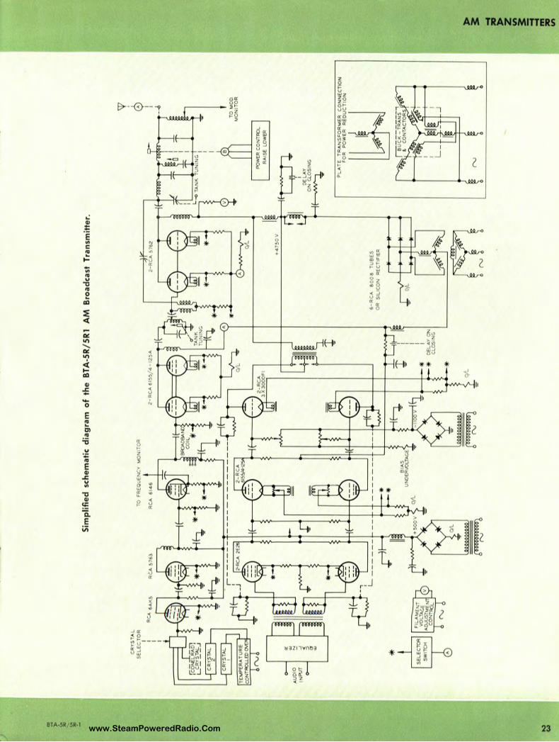
Sim
pli
fied
sch
emat
ic d
iagr
am o
f th
e B
TA
-SR
/SR
l A
M
Bro
adca
st T
rans
mit
ter.
RC
A 5
76
3 bo
oo~o
ooo 6
TO
F
RE
QU
EN
CY
M
ON
ITO
R
RC
A
61
46
o;1.
.
BIA
S
UN
DE
R\O
LTA
GE
!00
0~0
00
!
2-R
CA
615
5/4
• 12
5A
*
~
TA
NK
~
TU
NIN
G
q.
*'_,_
_ __
__
__
_ __,
1
+4
7!,
0 V
6-R
CA
8
00
8
TU
BE
S
OR
S
ILIC
ON
R
EC
TIF
IER
Of.-
[:Tl
PO
wm
CO
NT
RO
L
RA
ISE
LO
WER
1T
ON
CLO
SIN
G
~
TO
MO
D
MO
NIT
OR
PL
AT
E
TR
AN
SF
OR
ME
R
CO
NN
EC
TIO
N
FO
R
PO
WE
R
RE
DU
CT
ION
~ -t
~ z ~ 3 Ill
,a "'
www.SteamPoweredRadio.Com
AM TRANSMITTERS
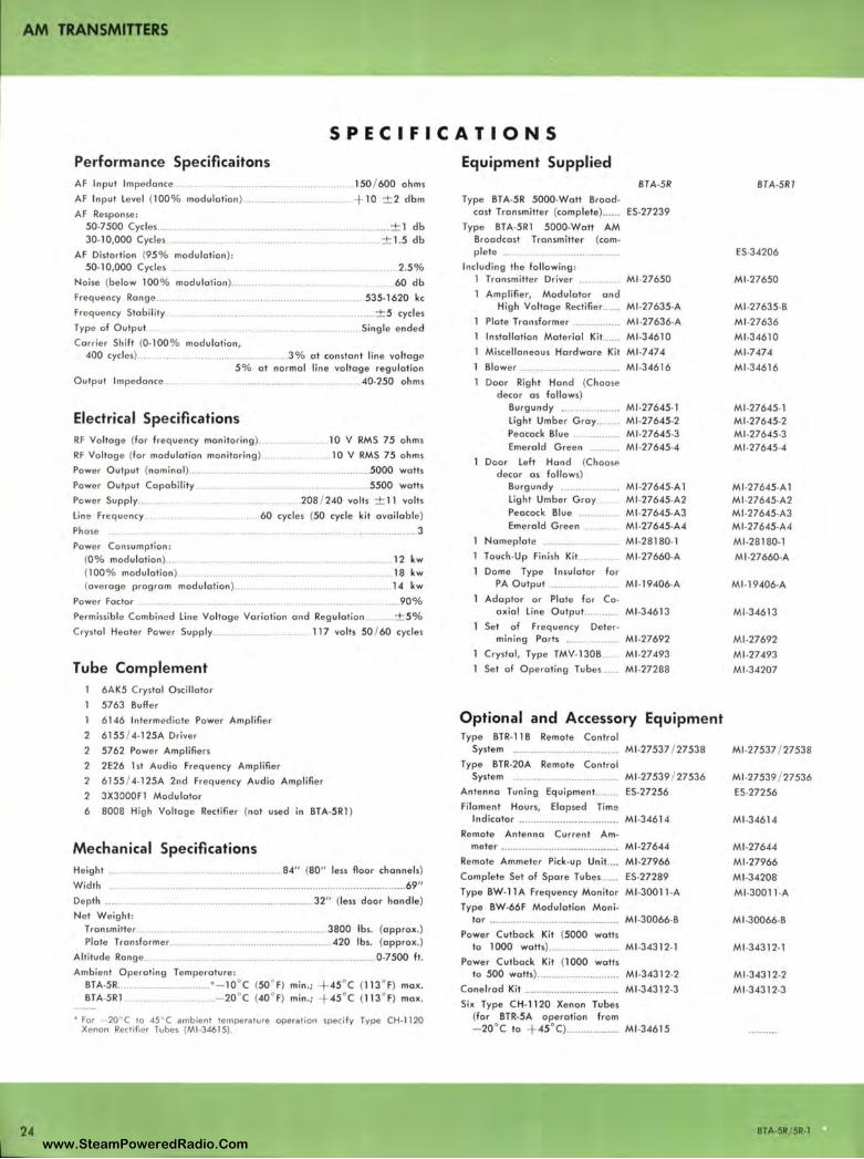
SPECIFICATIONS
24
Performance Specificaitons AF Input Impedance ... . .... ... . .........••.............. 150 / 600 ohms
AF Input Level {100% modulation ) .................................. + 10 ± 2 dbm
AF Response : 50-7500 Cycles ..... 30-10,000 Cycles
········ ................................................... ± 1 db
AF Distortion {95% modulation): 50-10,000 Cycles ..... .
Noise {below 100% modulation )
Frequency Range .....
Freque ncy Stability
Type of Output ..
Carrie r Sh ift (0-100% modulation,
...................................... ± 1.5 db
.. ...... •. ......... .. .. ... . .. .. .. 2.5%
. .. 60 db
.. 535-1620 kc
..... ± 5 cycles
Single e nded
400 cycles) ........... . . ... 3% at constant line voltage 5% at normal line voltage regulation
Output Im pedance ..... ............ ... .. .. . .40•250 ohms
Electrical Spe cifications RF Voltage {for frequency monitoring )
RF Voltage {for modulation monitoring ) ............ .
.. 10 V RMS 75 ohms
.10 V RMS 75 ohms
Power Output {nominal ) .......
Powe r Output Capabi lity .
Power Supply ....
Line Frequ ency
Phase ..
Power Consumption: {0 % modulation ) ..... {100% modulation) {average program modulation)
Power Factor
.. .......... 5000 watts
.. .. 5500 watts
... 208 / 240 volts ± 11 volts
60 cycles (50 cycle kit avai lable)
.... .. .................................... 3
. ..................................... 12 kw .................................... 18 kw
14 kw
.... 90%
Permissible Combined Line Voltage Variation and Reg ulat ion .. . .... ± 5 %
Crystal Heater Power Supply 117 volts 50 / 60 cycles
Tube Comple ment 6AK5 Crystal Osci llato r
5763 Suffer
1 6146 Intermediate Power Amplifier
2 6155 / 4-125A Driver
2 5762 Power Amplifiers
2 2E26 1st Audio Freque ncy Amplifier
2 6155 / 4• l 25A 2nd Frequency Audio Amplifie r 2 3X3000F1 Modulator
6 8008 High Voltage Rectifier {not used in 8TA-5Rl )
Me chanical Specifications Height ..
Width
Depth ......
Net Weig ht :
....... . .......... ............. 84" (80" less floor channels)
......................... ········ ········· ··············· ············· ·········· .. 69" .. ................................................... 32" {less door handle)
Transmitter ... ... ........... . ...................................... 3800 lbs. {approx .) Plate Transformer ......................................... .420 lbs. {approx.)
Altitude Range.... . ... .......................................................... .. 0•7500 ft.
Ambient Operating Temperature: BTA-5R . . . ......... *-10°C {50 ° F) min .; + 45°C {l 13° F) max. BTA-5Rl ............... - 20°C {40° F) min .; + 45 °C {113° F) max.
• For 20°C to 45 C ambient tempera ture operation speci fy Type CH-11 20 Xenon Rectifier Tubes (Ml-3461 5).
Equipment Supplied BTA.5R BT A-SRI
Type BTA-5R 5000-Watt Broad-cast Transmitter {complete) ...... ES.27239
Type BTA-5Rl 5000.watt AM Broadcast Transmitter {com-plete ....................................... ES.34206
Including the following : 1 Transmitter Driver .... ····•·· M1 •27650 Ml -27650
1 Amplifier, Modulato r and High Voltage Rectifier ..... . Ml •27635-A Ml -27635-B
Plate Transformer ................ Ml -27636-A Ml-27636
Installation Material Kit ..... Ml •34610 Ml -34610
Misce llan eous Hardware Kit Ml -7474 Ml -7474
Blower .................................. Ml -34616 Ml -34616
Door Right Hand {Choose decor as follows)
Burgundy ................... Ml•27645-1 Ml -27645-1 Lig ht Umber Gray ........ Ml-27645-2 Ml -27645•2 Peacock Blue ................ Ml -27645-3 Ml -27645-3 Emerald Green .......... Ml-27645•4 Ml -27645•4
Door Left Hand {Choose decor as follows)
Burgundy .......... ........ Ml-27645•A 1 Ml .27645•A 1 Light Umber Gray Ml •27645•A2 Ml -27645-A2 Peacock Blue .. ........ Ml-27645•A3 M1 •27645.A3 Emerald Gree n . Ml -27645-A4 Ml•27645•A4
Nameplate ......................... Ml-28180·1 Ml -28180-1
Touch-Up Finish Ki t... .... Ml -27660•A Ml .27660-A Dome Type Insulator for
PA Output ................ ...... Ml•l9406·A Ml•l9406·A Adaptor or Plate for Co•
axial Lin e Outpu t.. ........ Ml•34613 Ml .34613
Set of Frequency Deter• mining Parts ............... Ml.27692 Ml .27692
Crystal , Type TMV-130B Ml .27493 Ml .27493
Set of Operating Tubes ..... Ml .27288 Ml .34207
Optional and Accessory Equipment Type BTR-11 B Remote Control
System .. ....................... .......... . Ml •27537 / 27538 Ml•27537 / 27538 Type 8TR-20A Remote Control
System ....... .. ................. ... ....... Ml .27539 / 27536 Ml•27539 / 27536 Antenna Tun ing Equipment ........ ES.27256 ES.27256 Filament Hou rs, Elapsed Time
Indicator ............ ..................... . Ml .34614 Ml .34614 Remote Antenna Current Am-
meter .................... .................... M1 •27644
Remote Ammeter Pick-u p Unit .... Ml -27966
Complete Set of Spare Tubes ...... ES.27289
Type BW-llA Frequency Monitor Ml .3001l•A
Type BW-66F Modulation Moni-tor .................................. ·-······· Ml -30066·B
Power Cutback Kit (5000 watts to 1000 walls) ......... ... ............ Ml •343 l 2• 1
Power Cutback Kit (1000 watts lo 500 watts)... ....................... .. Ml .34312•2
Conelrad Kit .................... ............ Ml .34312•3
Six Type CH.1120 Xenon Tubes {for BTR•5A operation from - 20°C to + 45°C) .................. Ml .34615
Ml -27644
Ml -27966
Ml .34208
Ml -300ll •A
Ml•30066·B
Ml .34312•1
Ml.34312•2
Ml .34312•3
BTA•5R/ 5R•l www.SteamPoweredRadio.Com
AM TRANSMITTERS
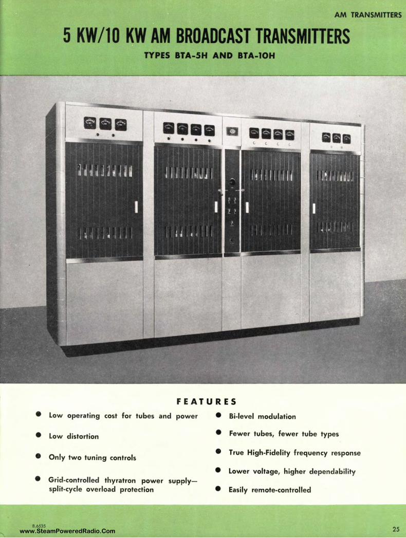
5 KW/10 KW AM BROADCAST TRANSMITTERS TYPES BTA-5H AND BTA-10H
111111 • •••• • •••
FEATURES
• Low operating cost for tubes and power • Bi-level modulation
• Low distortion • Fewer tubes, fewer tube types
• True High-Fidelity frequency response • Only two tuning controls
• Lower voltage, higher dependability
• Grid-controlled thyratron power supply-split-cycle overload protection • Easily remote-controlled
B.6535 25 www.SteamPoweredRadio.Com
AM TRANSMITTERS
26
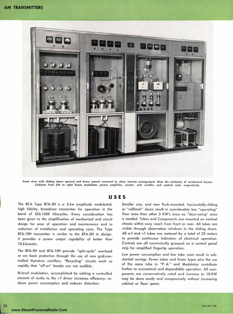
Front view with sliding doors opened and lower panels removed lo show interior arrangement. Note the similarity of mechanical layout. Cabinets from left to right house modulator, power amp Ii Iler, exciter, and rectifier and control units respectively.
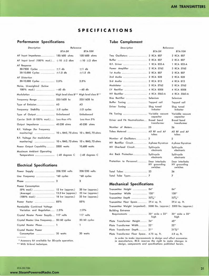
USES The RCA Type BTA-5H is o 5-kw amplitude modulated , high fidelity, broadcast transmitter for operation in the bond of 535-1620 kilocycles. Every consideration hos been given to the simplification of mechanical a nd circuit design for ease of operation and maintenance and to reduction of installation and operating costs. The Type BTA-1 OH transmitter is similar to the BT A-5H in design. It provides o power output capability of better than l 0-kilowatts.
The BTA-5H and BT A-1 OH provide "split-cycle" overload or arc bock protection through the use of new grid-controlled thyratron rectifiers. "Recycling" circuits work so rapidly that "off-on" breaks ore not audible.
Bi-level modulation, accomplished by adding a controlled amount of audio to the r-f driver increases efficiency, reduces power consumption and reduces distortion.
Smaller size, and new flush -mounted, horizontally-sliding or "rollback" doors result in considerably less " ope rating" floor area than other 5 KW's since no "door-swing" area is needed. Tubes and Components are mounted on vertical chassis within easy reach from front or rear. All tubes ore visible through observation windows in the sliding doors. All o-f and r-f tubes ore metered by a total of 23 meters to provide continuous indication of electrical operation. Controls ore all conveniently grouped on o central panel strip for simplified fingertip operation.
Low power consumption and low tube costs result in substantial savings. Fewer tubes and fewer types plus the use of the some tube in " P. A." and Modulator contribute further to economical and dependable operation. All components are conservatively rated and increase to l 0-KW may be done easily and inexpensively without increasing cabinet or floor space.
BTA-5H/10H
www.SteamPoweredRadio.Com
wigfi
Stolen 2 Line Transparent
DESCRIPTION The Type BT A-5H/ l OH AM Broadcast Transmitters are outstanding in appearance, performance and reliability. Fidelity, distortion, and noise level are held to standards meeting the highest requirements. The power output capability is conservatively rated at 5500 and l 0,600 watts respectively. The frequency range of the equipment is 535 to 1620 kc.
The entire transmitter consists of four rugged steel and aluminum cabinets housing the exciter, power amplifier, modulator, and power rectifier and control units respectively. These cabinets are installed side by side on two 4-inch wire troughs (supplied) which run the full length of the transmitter. These individual cubicles simplify shipping and installation of the transmitter, and when assembled provide an attractive unified appearance.
The cabinets feature unique aluminum sliding doors which slide back effortlessly on rubber castor assemblies. These flush-mounted doors save operating floor space and provide more "walk-around" area in compact transmitter rooms. Vertical chassis construction is emoloyed throughout both the BT A-5H ond BT A-1 OH Transmitters. This provides utmost accessibility to all components without disassembly by merely rolling back the front or rear doors.
All operating tubes are visible through convenient observation windows in the doors. The centralized grouping of the two tuning controls, with all meters grouped on panels above the doors provide ease of operation. All doors are provided with conventional plate inter-lock and high voltage grounding switches for protection of operating personnel.
Circuit Description
The BTA-5H and BT A-1 OH Transmitters are supplied with two UL-4392 Oscillator Units equipped with TMV- l 29B
Schematic of Bi-level modulation circuit.
BTA-SH / lOH
AM TRANSMITTERS
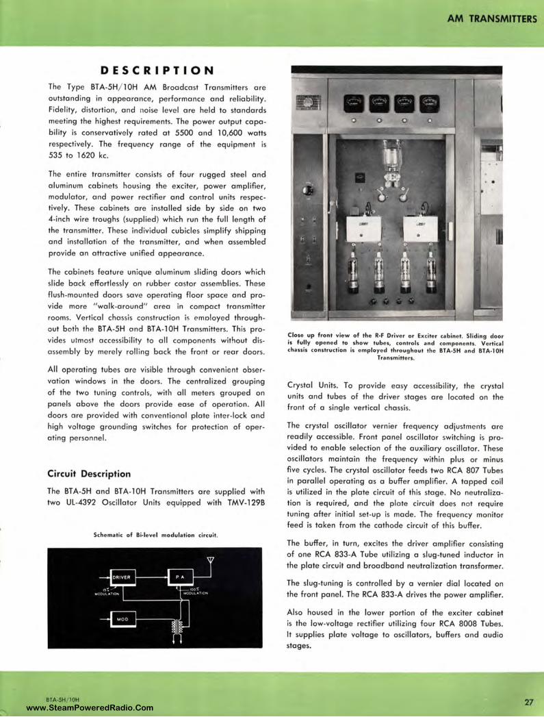
Close up front view of the R-F Driver or Exciter cabinet. Sliding door is fully opened to show tubes, controls and components. Vertical chassis construction is employed throughout the BTA-SH and BTA-lOH
Transmitters.
Crystal Units. To provide easy accessibility, the crystal units and tubes of the driver stages are located on the front of a single vertical chassis.
The crystal oscillator vernier frequency adjustments are readily accessible . Front panel oscillator switching is provided to enable selection of the auxiliary oscillator. These oscillators maintain the frequency within plus or minus five cycles. The crystal oscillator feeds two RCA 807 Tubes in parallel operating as a buffer amplifier. A tapped coil is utilized in the plate circuit of this stage. No neutralization is required, and the plate circuit does not require tuning after initial set-up is made. The frequency monitor feed is taken from the cathode circuit of this buffer.
The buffer, in turn, excites the driver amplifier consisting of one RCA 833-A Tube utilizing a slug-tuned inductor in the plate circuit and broadband neutralization transformer.
The slug-tuning is controlled by a vernier dial located on the front panel. The RCA 833-A drives the power amplifier.
Also housed in the lower portion of the exciter cabinet is the low-voltage rectifier utilizing four RCA 8008 Tubes. It supplies plate voltage to oscillators, buffers and audio stages.
27 www.SteamPoweredRadio.Com
AM TRANSMITIERS
28
The Power Amplifier or r-f output stage consists of two
RCA-5762 Tubes, in the BTA-5H for 5-kw operation. A
third RCA 5762 is added in the final of the BTA-l0H for
l 0-kw operation.
The plate circuit of this modulated power amplifier is tuned
by a variable vacuum capacitor which is controlled
manually by a vernier dial located on the front panel.
Neutralization is accomplished by means of a broadband
transformer. The power amplifier tank circuit and output
matching network form a symmetrical network so the load
impedance is the same to both side bands, thus eliminating
a possible source of distortion. The modulation monitor
feed is provided by a transformer across the output of the
transmitter to provide faithful monitoring of transmitter
output. There are no air dielectric condensers in the trans
mitter, thus reducing arc-over possibilities due to dust
collection. There are only two tuning controls and one
power output control in the transmitter. All r-f stages
operate Class C.
Use of the RCA-5762 tubes in both the power amplifier
and modulator stages not only reduces number of tube
types, but makes possible interchange of tubes to increase
useful life.
Low audio distortion at frequencies from 30 to 15,000
cycles per second is achieved. This is accomplished by im
proved audio circuit design, and by modulating the plate
of the r-f driver as well as the power amplifier. Bi-level
modulation improves the linearity of the power amplifier by
varying the drive in proportion to the modulation. Hum
and distortion is further reduced by utilizing inverse feed
back in the audio section of the transmitter.
The audio amplifier consists of two RCA-807 Tubes operat
ing push-pull Class A, resistance coupled to two RCA-828
Tubes, also operating push-pull Class A. These tubes are .
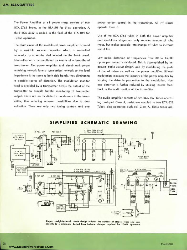
SIMP LIFIED SCHEMATIC DRAW IN G
.... INPUT
RC..,· &33 " 2 FIC" ~792 (~ KW) 3 RC" ~762 (10 KW)
MODULAT IO N MONITOR
Simple, straightforward, circuit design reduces the number of stages, tubes and com• ponents to • minimum, Dotted lines indica-te changes required for 10-KW operation.
BTA-SH/ lOH www.SteamPoweredRadio.Com
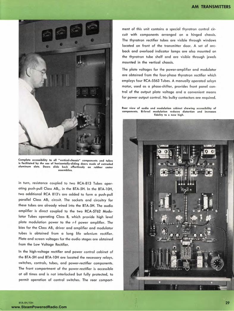
Complete accessibility to all " vertical-chassis" components and tubes is facilitated by the use of horizontally-sliding doors made of extruded aluminum slats . Doors slide back effortlessly on rubber caster
assemblies.
in turn, resistance coupled to two RCA-813 Tubes oper
ating push-pull Class AB1, in the BTA-5H. In the BTA-1 OH,
two additional RCA 813's are added to form a push-pull
parallel Class AB1 circuit. The sockets and circuitry for
these tubes are already wired into the BTA-5H. The audio
amplifier is direct coupled to the two RCA-5762 Modu
lator Tubes operating Class B, which provide high level
plate modulation power to the r-f power ampl ifier. The
bias for the Class AB1 driver and amplifier and modulator
tubes is obtained from a long life selenium rectifier.
Plate and screen voltages for the audio stages are obtained
from the Low Voltage Rectifier.
In the high-voltage rectifier and power control cabinet of
the BTA-5H and BTA-1 OH are located the necessary relays,
switches, controls, tubes, and power-rectifier components.
The front compartment of the power-rectifier is accessible
at all times and is not interlocked but fully protected, to
permit operation of control switches. The rear comport-
BTA-5H/IOH
AM TRANSMITTERS
ment of this unit contains a special thyratron control ci r
cuit with components arranged on a hinged chassis.
The thyratron rectifier tubes are visible through windows
located on front of the transmitter door. A set of arc
back and overload indicator lamps are also mounted on
the thyratron tube shelf and are visible through jewels
mounted in the vertical chassis.
The plate voltages for the power-amplifier and modulator
are obtained from the four-phase thyratron rectifier which
employs four RCA-5563 Tubes. A manually operated se lsyn
motor, used as a phase-shifter, provides front panel con
trol of the output plate voltage and a convenient means
for power output control. No bulky contactors are required .
Rear view of audio and modulation cabine t showing accessibility of components. Bi-level modulation reduces distortion and increases
fidelity to a new high .
29 www.SteamPoweredRadio.Com
AM TRANSMITTERS
30
Split-cycle electronic overload or arc-back protection in the HV rectifier is provided, with positive arc-back indication. Automatic recycling of the overload and arc-back protective circuits is another incorporated feature.
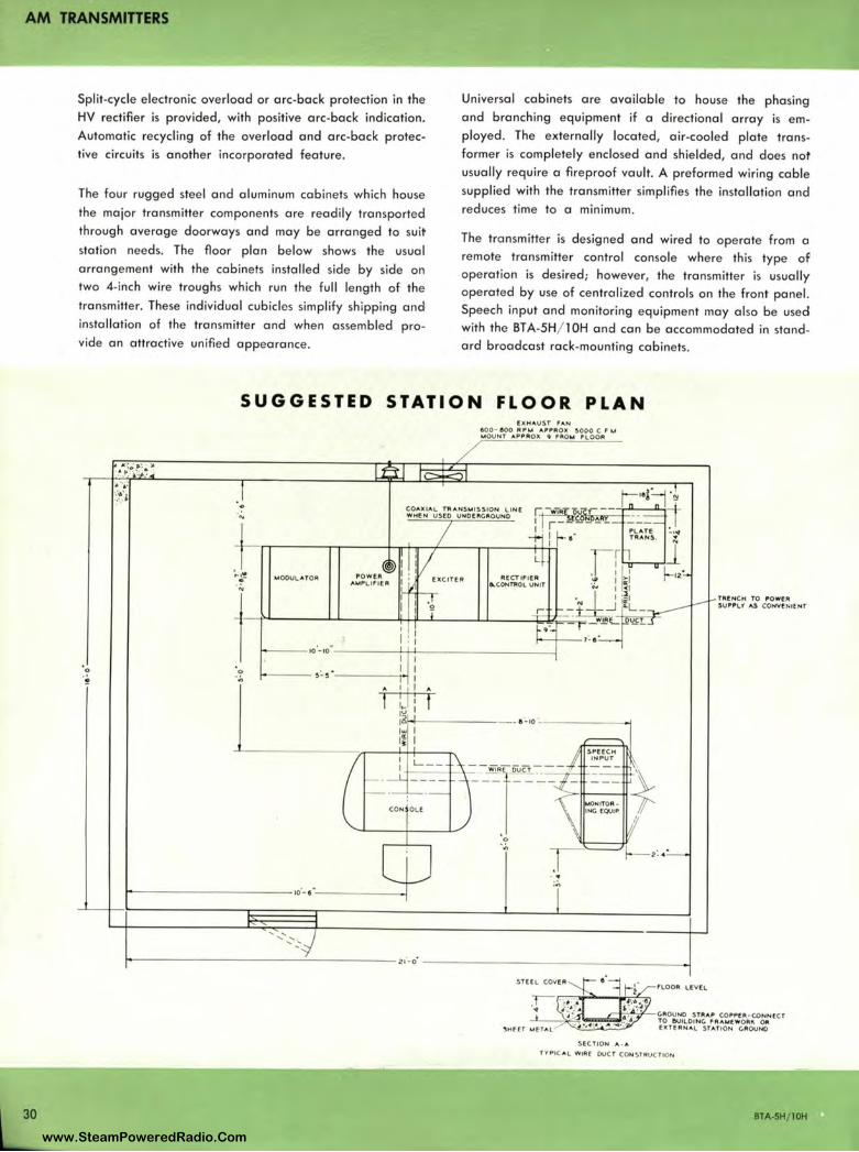
The four rugged steel and aluminum cabinets wh ich house the major transmitter components are readily transported through average doorways and may be arranged to suit station needs. The floor plan below shows the usual arrangement with the cabinets installed side by side on two 4-inch wire troughs which run the full length of the transmitter. These individual cubicles simplify shipping and installation of the transmitter and when assembled provide an attractive unified appearance .
Universal cabinets are available to house the phasing and branching equipment if a directional array is employed. The externally located, air-cooled plate transformer is completely enclosed and shielded, and does not usually require a fireproof vault. A preformed wiring cable supplied with the transmitter simplifies the installation and reduces time to a minimum.
The transmitter is designed and wired to operate from a remote transmitter control console where this type of operation is desired; however, the transmitter is usually operated by use of centralized controls on the front panel. Speech input and monitoring equipment may also be used with the BT A-5H/ l OH and can be accommodated in standard broadcast rack-mounting cabinets.
SUGGESTED STATION FLOOR PLAN
.,, ...
MODULATOR
A
i-------------- ,o·- a"------~
' ' ...................
fX HAUST r:AN 600- 600 RPM APPR OX ~000 C. r J.A ..,.OUNT APPR O)I. Q FRO l.4 f'LOOR
.. ;~
~ -------------------21·- o· ---------------------..1 fLOOR LEll f. L
SECTION A - A
fYPI CA L WIR( DUCT COM ST RUCTION
TR!.NCH TO POWl!:R su ,ftL'f A$ CONVe ,-;: 1fNT
BTA-5H/ 10H
www.SteamPoweredRadio.Com
AM TRANSMITTERS
SPECIFICATIONS
Performance Specifications
Description Reference
BTA-5H BT A-JOH
AF Input Impedance ........... ....... .. 150/ 600 ohms
AF Input level (100% mod .) .... + 10 ± 2 dbm
AF Response
50-7500 Cycles
30-10,000 Cycles
AF Distortion
50-10,000 Cycles
Noise, Unweighted (below
± 1 db
± 1.5 db
2.5 %
100% mod.) .......................... - 60 db
150 / 600 ohms
+ 10 ± 2 dbm
± 1 db
± 1.5 db
2.5%
- 60 db
Modulation ..... ............................. High level class 8** High level class 8**
Frequency Range ......... ..... .......... 535-1620 kc 535-1620 kc
Type of Emission ................... ....... A3 A3
Frequency Stability .................. ± 5 cycles ± 5 cycles
Type of Output .. ................. .. ..... Unbalanced Unbalanced
Carrier Shilt (0-100% mad.) ...... less than 4% less than 5%
Output Impedance .................... 40-250 ohms 40-250 ohms
R.F. Voltage (for frequency
monitoring) ...... ............... .. ..... 10 v. RMS, 75 ohms 10 v. RMS, 75 ohms
R.F. Voltage (for modulation
monitoring) 10 v. RMS, 75 ohms 10 v. RMS, 75 ohms
Power Output Capability ............ 5500 watts
Maximum Ambient Operating
Temperature ............................ + 45 degrees C
Electrical Specifications
Power Supply .. .. .... .................... 208/230 volts
line Frequency .......................... *60 cycles
Phase ................................ ... ....... 3
Power Consumption
(0% mod.) .................... ..... ..... 12 kw (approx.)
(Average} ................................ 13.5 kw (approx.)
(100% mod.) ..... ............ ......... 18 kw (approx.}
Power Factor ......... ........... ........ 85%
Permissible Combined Voltage
Variation and Regulation ...... ± 5%
Crystal Heater Power Supply.... 117 volts
Crystal Heater line Frequency .... 50 / 60 cycles
Crystal Heater Phase ................. .
Crystal Heater Power
Consumption 30 watts
* Accessory kit available for 50-cycle operation.
•• With bi-level technique.
BTA-5H/IOH
10,600 watts
+ 45 degrees C
208 / 230 volts
*60 cycles
3
20 kw (approx.)
23 kw (approx.)
33 kw (approx.)
85%
± 5%
117 volts
50/ 60 cycles
30 watts
Tube Complement
Description Reference
BTA-5H BT A-JOH
Two Oscillators ... ....................... 2 RCA 807
Buffer .......................................... 2 RCA 807
R.F. Driver .. .............................. .
Power Amplifier
RCA 833-A
2 RCA 5762
1st Audio ....................... ......... ... 2 RCA 807
2nd Audio
3rd Audio
Modulator
lV Rectifier
HY Rectifier
2 RCA 828
2 RCA 813
2 RCA 5762
4 RCA 8008
4 RCA 5563-A
Bias Rectifier ........ ...................... Selenium
Buffer Tuning
Driver Tuning
PA Tuning
Tapped coil
Slug tuned inductor
Variable vacuum capacitor
Driver and PA Neutralization .... Broad band transformer
Number of Meters ........... ... ........ 23
Tubes Metered ............................ All RF and AF tubes
Number of Oscillators ....... ...... ... 2
HY Rectifier Circuit .................... 4-phase thyratron
HY Overload Circuit........ .... ...... Split-cycle e lectronic
Arc Back Protection.................... Split-cycle electronic
Protection to Personnel.. ..... .. ..... Door interlocks HY grounding
switches
Total Tubes ................................ 23
Total Tube Types ........................ 7
Mechanical Specifications Transmitter Height
Transmitter Width
84"
130"
Transmitter Depth ...................... 32K6"
2 RCA 807
2 RCA 807
RCA 833-A
3 RCA 5762
2 RCA 807
2 RCA 828
4 RCA 813
2 RCA 5762
4 RCA 8008
4 RCA 5563-A
Selenium
Tapped coil
Slug tuned inductor
Variable vacuum capacitor
Broad band transformer
26
All RF and AF tubes
2
4-phase thyratron
Split-cycle electronic
Split-cycle electronic
Door interlocks HY grounding
switches
26
7
84 11
130"
32K6''
Transmitter Floor Space .............. 29.4 sq. ft . 29.4 sq . ft .
Transmitter Weight (unpacked ) .. 5300 lbs. (approx.) 5500 lbs. (approx .)
Building Entrance
Requirements .................. ........ 30" wide X JJ" 30" wide X 33"
Plate
Plate
Plate
Plate
high high
Transformer Height .......... 34" 45"
Transformer Width ............ 22" 22"
Transformer Depth ............ 31" 31 ½ "
Transformer Floor Space .. 4.75 sq. ft. 4.8 sq . ft .
In order to make improvements in design and effe ct economies in manufacture, RCA reserves the right to make changes in
design, components and specifications published herein .
31 www.SteamPoweredRadio.Com
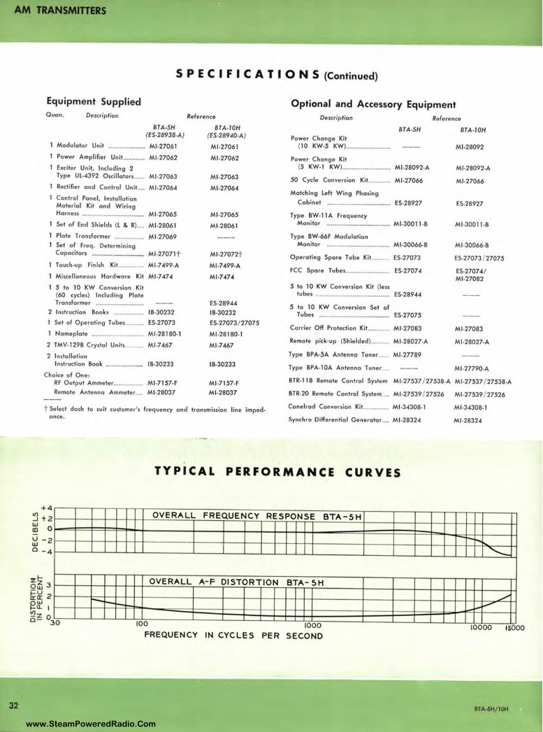
AM TRANSMITTERS
32
S P E C I F I C A T I O N S (Continued)
Equipment Supplied Optional and Accessory Equipment Quan. Description
Modulator Unit
BTA-SH (ES-28938-A)
Ml-27061
Power Amplifier Unit ...... ...... Ml -27062
Exciter Unit, Including 2 Type UL-4392 Oscillators ...... Ml-27063
Rectifier and Control Unit .... Ml -27064
Control Panel, Installation Material Kit and Wiring Harness .................................. Ml-27065
Set of End Shields (L & R).... Ml-28061
Plate Transformer ................ Ml.27069 Set of Freq. Determining Capacitors ·························-· Ml -27071 t Touch-up Finish Ki t... ........... Ml -7499-A
Miscellaneous Hardware Kit Ml -7474
5 to 10 KW Conversion Kit (60 cycles) Including Plate Transformer ......................... .
2 Instruction Books .... .. ... ....... IB.30232 1 Set of Operating Tubes .......... ES•27073
1 Nameplate .. ......................... . Ml -28180-1
2 TMV-129B Crystal Units .......... Ml -7467
2 Installation Instruction Book ..................•• IB-30233
Reference
BTA-I0H (ES-28940-A)
Ml-27061
Ml -27062
Ml -27063
Ml -27064
Ml -27065
Ml -28061
Ml -27072t
Ml -7499-A
Ml-7474
ES-28944 IB-30232
ES-27073/27075
Ml-28180-1
Ml -7467
IB-30233
Description
BTA-5H Power Change Kit
(10 KW-5 KW) ...... ................. .
Power Change Kit (5 KW-1 KW) .......................... Ml-28092-A
50 Cycle Conversion Kit............ Ml-27066
Matching Left Wing Phasing Cabinet .................................. ES-28927
Type BW-11 A Frequency Monitor .................................. Ml -30011 -B
Type BW•66F Modulation Monitor .................................. Ml -30066-B
Operating Spare Tube Kit .......... ES-27073
FCC Spare Tubes ............. ........... ES-2707 4
5 to 10 KW Conversion Kit (less tubes ................................ .. ...... ES-28944
5 to 10 KW Conversion Set of Tubes .................................•.... ES.27075
Carrier Off Protection Kit ............ Ml -27083
Remote pick-up (Shielded) .......... Ml-28027-A
Type BPA-5A Antenna Tuner ...... Ml -27789
Type BPA-l0A Antenna Tuner ... .
Reference
BTA-I0H
Ml-28092
Ml-28092-A
Ml -27066
ES-28927
Ml -30011 -8
Ml -30066-B
ES-27073 / 27075
ES-27074/ Ml -27082
Ml -27083
Ml -28027-A
MJ .27790-A Choice of One:
RF Output Ammeter ................ Ml-7157-F Ml-7157-F Ml -28037
BTR-118 Remote Control System Ml -27537 / 27538-A MJ .27537 / 27538.A
Remote Antenna Ammeter .... Ml -28037 BTR-20 Remote Control System .. .. Ml -27539 / 27526 Ml -27539 / 27526
t Select dash to suit customer's frequency and transmission line impedance.
Conelrad Conversion Kit .............. Ml -34308-1
Synchro Differential Generator .... Ml -28324
+ 4 '.'.l + 2 ~ 0
~ -2 0 -4
1-Z z 3 Ow ~~ 2 8~ I ~z o o- 30
r-~ ......
TYPICAL PERFORMANCE CURVES
OVERALL FREQUENCY RESPONSE BTA-SH
OVERALL A-F DISTORTION BTA- 5H
JOO 1000 FREQUENCY IN CYCLES PER SECOND
Ml-34308-1
Ml -28324
-r--r--- .... ......__
_/
_i,.- i.----
10000 15000
BTA-5H/ IOH
www.SteamPoweredRadio.Com

AM TRANSMITIERS
50 KW "AMPLIPHASE" AM TRANSMITTER TYPE BTA-50G
FEATURES
• Requires less than 80 square feet of floor • Excellent frequency response space-smaller than many 5 kw transmitters
• Internal blowers-no air-ducts necessary • Uses long life RCA 5671 tubes
• Cuts tube costs in half • Designed for remote-control operation
• Lowest operating cost ever offered in a 50 kw transmitter • Uses fewer major components than any
other transmitter of similar p,,wer for max-
• Low R-F harmonic distortion imum dependability
8.65«) 33 www.SteamPoweredRadio.Com
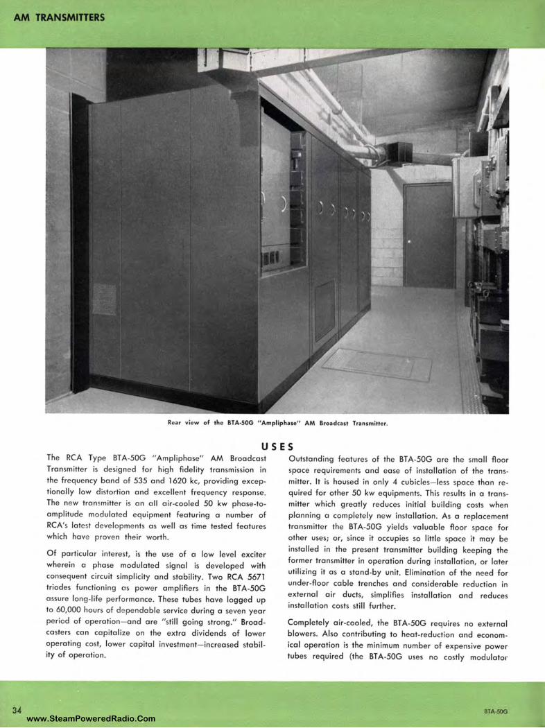
AM TRANSMITTERS
34
Rear view of the BTA-SOG " Ampliphase" AM Broadcast Transmitter.
USES The RCA Type BTA-50G "Ampliphase" AM Broadcast Transmitter is designed for high fidelity transmission in the frequency band of 535 and 1620 kc, providing exceptionally low distortion and excellent frequency response . The new transmitter is an all air-cooled 50 kw phase-toamplitude modulated equipment featuring a number of RCA's latest developme nts as well as time tested features which have proven their worth .
Of particular interest, is the use of a low level exciter wherein a phase modulated signal is deve loped with consequent circuit simplicity and stability. Two RCA 5671 triodes functioning as power amplifiers in the BT A-50G assure long-life performance. These tubes have logged up to 60,000 hours of de pendable service during a seven year period of operation- and are "still going strong." Broadcasters can capitalize on the extra dividends of lower operating cost, lower capital investment- increased stability of operation.
Outstanding features of the BT A-50G are the small floor space requirements and ease of installation of the transmitter. It is housed in only 4 cubicles- less space than required for other 50 kw equipments. This results in a transmitter which greatly reduces initial building costs when planning a completely new installation. As a replacement transmitter the BT A-50G yields valuable floor space for other uses; or, since it occupies so little space it may be installed in the present transmitter building keeping the former transmitter in operation during installation, or later utilizing it as a stand-by unit. Elimination of the need for under-floor cable trenches and considerable reduction in external air ducts, simplifies installation and reduces installation costs still further.
Completely air-cooled, the BT A-50G requires no external blowers. Also contributing to heat-reduction and economical operation is the minimum number of expensive power tubes required (the BTA-50G uses no costly modulator
BTA-SOG www.SteamPoweredRadio.Com
wigfi
Stolen 2 Line Transparent
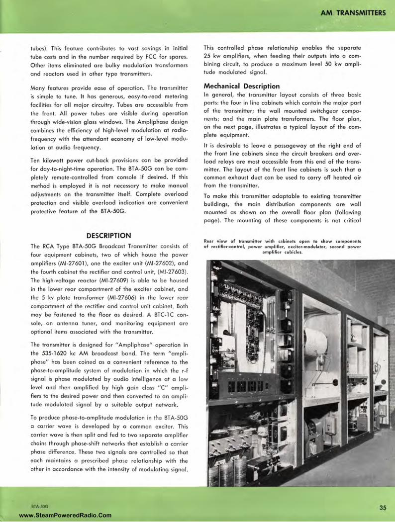
tubes). This feature contributes to vast savings in initial
tube costs and in the number required by FCC for spares.
Other items eliminated are bulky modulation transformers
and reactors used in other type transmitters.
Many features provide ease of operation. The transmitter
is simple to tune. It has generous, easy-to-read metering
facilities for all major circuitry. Tubes ore accessible from
the front. All power tubes are visible during operation
through wide-vision glass windows. The Ampliphase design
combines the efficiency of high-level modulation at radio
frequency with the attendant economy of low-level modu
lation at audio frequency.
Ten kilowatt power cut-back prov1s1ons can be provided
for day-to-night-time operation. The BT A-50G can be com
pletely remote-controlled from console if desired. If this
method is employed it is not necessary to make manual
adjustments on the transmitter itself. Complete overload
protection and visible overload indication ore convenient
protective feature of the BT A-50G.
DESCRIPTION The RCA Type BT A-50G Broadcast Transmitter consists of
four equipment cabinets, two of which house the power
amplifiers (Ml-27601 ), one the exciter unit (Ml-27602), and
the fourth cabinet the rectifier and control unit, (Ml-27603) .
The high-voltage reactor (Ml-27609) is able to be housed
in the lower rear compartment of the exciter cabinet, and
the 5 kv plate transformer (Ml-27606) in the lower rear
comportment of the rectifier and control unit cabinet. Both
may be fastened to the floor as desired . A BTC-1 C con
sole, an antenna tuner, and monitoring equipment ore
optional items associated with the transmitter.
The transmitter is designed for "Ampliphase" operation in
the 535-1620 kc AM broadcast band. The term "ampli
phase" has been coined as a convenient reference to the
phase-to-amplitude system of modulation in which the r-f
signal is phase modulated by audio intelligence at a low
level and then amplified by high gain class "C" ampli
fiers to the desired power and then converted to an ampli
tude modulated signal by a suitable output network.
To produce phase-to-amplitude modulation in the BT A-50G
a carrier wave is developed by a common exciter. This
carrier wave is then split and fed to two separate amplifier
chains through phase-shift networks that establish a carrier
phase difference. These two signals ore controlled so that
each maintains a prescribed phase relationship with the
other in accordance with the intensity of modulating signal.
BTA-SOG
AM TRANSMITTERS
This controlled phase relationship enables the separate 25 kw amplifiers, when feeding their outputs into a combining circuit, to produce a maximum level 50 kw amplitude modulated signal.
Mechanical Description In general, the transmitter layout consists of three basic parts: the four in line cabinets which contain the major port of the transmitter; the wall mounted switchgear components; and the main plate transformers. The floor plan, on the next page, illustrates a typical layout of the complete equipment.
It is desirable to leave a passageway at the right end of the front line cabinets since the circuit breakers and overload relays ore most accessible from this end of the transmitter. The layout of the front line cabinets is such that a common exhaust duct can be used to carry off heated air from the transmitter.
To make this transmitter adaptable to existing transmitter buildings, the main distribution components ore wall mounted as shown on the overall floor plan (following page). The mounting of these components is not critical
Rear view of transmitter with cabinets open to show components of rectifier-control, power amplifier, exciter-modulator, second power
amplifier cubicles.
3S www.SteamPoweredRadio.Com
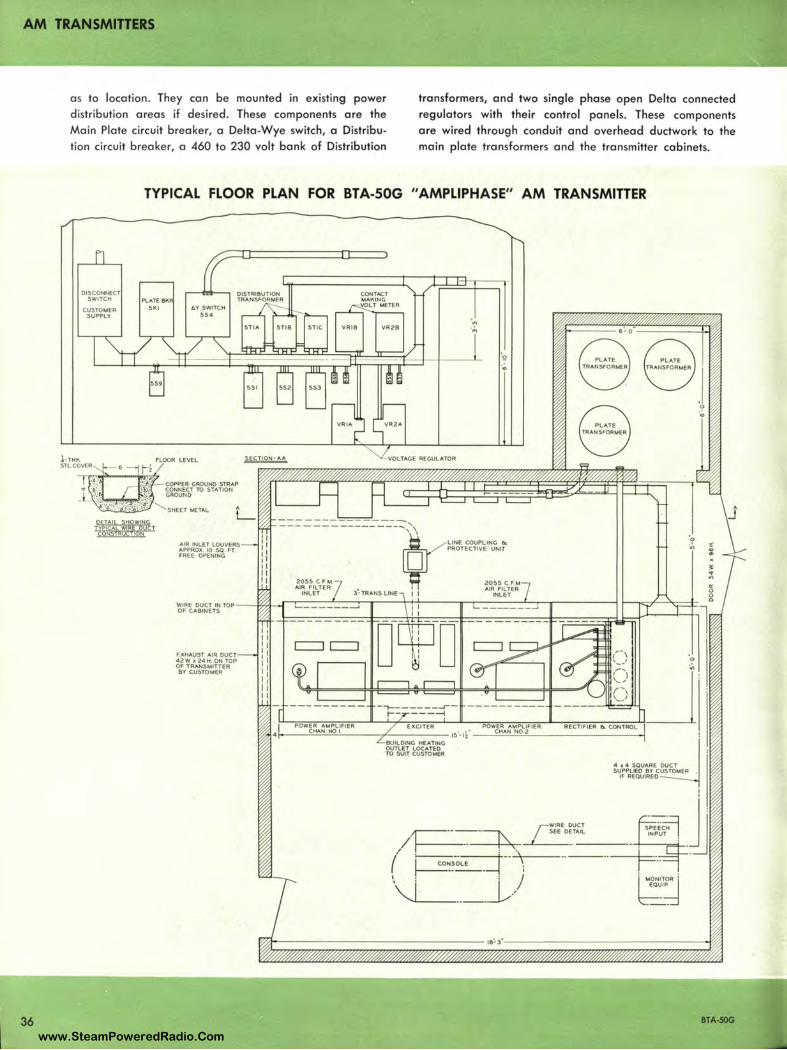
AM TRANSMITTERS
36
a s to location. They can be mounted in existing power distribution areas if desired. These components are the Main Plate circuit breaker, a Delta-Wye switch, a Distribution circuit breake r, a 460 to 230 volt bank of Distribution
transformers, and two single phase open Delta connected regulators with their control panels. These components are wired through conduit and overhead ductwork to the main plate transformers and the transmitter cabinets.
DISCONNECT SWITCH
CUSTOMER SUPPLY
TYPICAL FLOOR PLAN FOR BTA-S0G "AMPLIPHASE" AM TRANSMITTER
Pl.ATE BK 5KI AY SWITCH
5'4
COPPER GROUND STRAP CONNECT TO STATION GROUND
SHEET METAL
AIR INLET LOUVERS APPROX IO SO FT FREE OPENING
EXHAUST AIR DUCT 42W it24H. ON TOP OF TRANSMITTER ev CUSTOMER
CONTACT MAKING VOLT METER
I/RIB VR2B
-------------------------------,'\
·.., ·,;,
LINE COUPLING 8c PROTECTIVE UNIT
2055 CF M 2055 C FM AIR FILTER AIR FILTER
INLET I I lNLET
POWER AMPLIFIER EXCITER POWER AMPLIFIER f----'C""HA'-'N"-"N0"-'-1 ----'------- 1s·-1f--.::;CHccA.::;M'-'N0=2,_ _________ -I
BUILDING HEATING OUTLET LOCATED TO SUIT CUSTOMER
~lRE DUCT ,,---- - -~ LEE DE·T-AI_L ____ -!-----.==4-/ ~ .. ~,--
( j co~~-_oL_• _ _ j ·-·-\-;---··---·· \ : i / "'L_ ____ _l.,/
~ .. "' "' 0 0 0
BTA-SOG
www.SteamPoweredRadio.Com
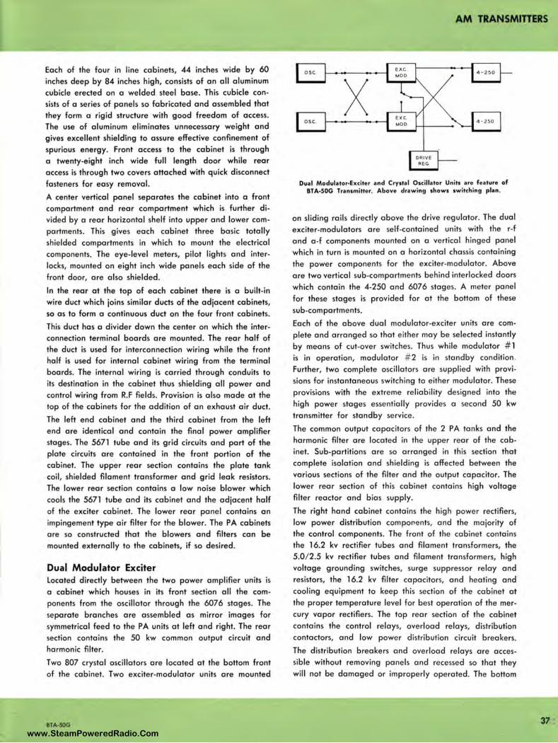
Each of the four in line cabinets, 44 inches wide by 60
inches deep by 84 inches high, consists of an all aluminum
cubicle erected on a welded steel base. This cubicle con
sists of a series of panels so fabricated and assembled that
they form a rigid structure with good freedom of access.
The use of aluminum eliminates unnecessary weight and
gives excellent shielding to assure effective confinement of
spurious energy. Front access to the cabinet is through
a twenty-eight inch wide full length door while rear
access is through two covers attached with quick disconnect
fasteners for easy removal.
A center vertical panel separates the cabinet into a front
compartment and rear compartment which is further di
vided by a rear horizontal shelf into upper and lower com
partments. This gives each cabinet three basic totally
shielded compartments in which to mount the electrical
components. The eye-level meters, pilot lights and inter
locks, mounted on eight inch wide panels each side of the
front door, are also shielded.
In the rear at the top of each cabinet there is a built-in
wire duct which joins similar ducts of the adjacent cabinets,
so as to form a continuous duct on the four front cabinets.
This duct has a divider down the center on which the inter
connection terminal boards are mounted. The rear half of
the duct is used for interconnection wiring while the front
half is used for internal cabinet wiring from the terminal
boards. The internal wiring is carried through conduits to
its destination in the cabinet thus shielding all power and
control wiring from R.F fields. Provision is also made at the
top of the cabinets for the addition of an exhaust air duct.
The left end cabinet and the third cabinet from the left
end are identical and contain the final power amplifier
stages. The 5671 tube and its grid circuits and part of the
plate circuits are contained in the front portion of the
cabinet. The upper rear section contains the plate tank
coil, shielded filament transformer and grid leak resistors.
The lower rear section contains a low noise blower which
cools the 5671 tube and its cabinet and the adjacent half
of the exciter cabinet. The lower rear panel contains an
impingement type air filter for the blower. The PA cabinets
are so constructed that the blowers and filters can be
mounted externally to the cabinets, if so desired.
Dual Modulator Exciter Located directly between the two power amplifier units is
a cabinet which houses in its front section all the com
ponents from the oscillator through the 6076 stages. The
separate branches are assembled as mirror images for
symmetrical feed to the PA units at left and right. The rear
section contains the 50 kw common output circuit and
harmonic filter.
Two 807 crystal oscillators are located at the bottom front
of the cabinet. Two exciter-modulator units are mounted
BTA-SOG
AM TRANSMITTERS
osc.
X osc.
DRIVE REG
4 -2 50
4 - 250
Dual Modulator-Exciter and Crystal Oscillator Units are feature of BTA-S0G Transmitter. Above drawing shows switching plan.
on sliding rails directly above the drive regulator. The dual
exciter-modulators are self-contained units with the r-f
and a -f components mounted on a vertical hinged panel
which in turn is mounted on a horizontal chassis containing
the power components for the exciter-modulator. Above
are two vertical sub-compartments behind interlocked doors
which contain the 4-250 and 6076 stages. A meter panel
for these stages is provided for at the bottom of these
sub-compartments.
Each of the above dual modulator-exciter units are com
plete and arranged so that either may be selected instantly
by means of cut-over switches. Thus while modulator # 1
is in operation, modulator # 2 is in standby condition .
Further, two complete oscillators are supplied with provi
sions for instantaneous switching to either modulator. These
provisions with the extreme reliability designed into the
high power stages essentially provides a second 50 kw
transmitter for standby service.
The common output capacitors of the 2 PA tanks and the
harmonic filter are located in the upper rear of the cab
inet. Sub-partitions are so arranged in this section that
complete isolation and shielding is affected between the
various sections of the filter and the output capacitor. The
lower rear section of this cabinet contains high voltage
filter reactor and bias supply.
The right hand cabinet contains the high power rectifiers,
low power distribution components, and the majority of
the control components. The front of the cabinet contains
the 16.2 kv rectifier tubes and filament transformers, the
5.0/2.5 kv rectifier tubes and filament transformers, high
voltage grounding switches, surge suppressor relay and
resistors, the 16.2 kv filter capacitors, and heating and
cooling equipment to keep this section of the cabinet at
the proper temperature level for best operation of the mer
cury vapor rectifiers. The top rear section of the cabinet
contains the control relays, overload relays, distribution
contactors, and low power distribution circuit breakers.
The distribution breakers and overload relays are acces
sible without removing panels and recessed so that they
will not be damaged or improperly operated. The bottom
37 www.SteamPoweredRadio.Com

AM TRANSMITTERS
38
rear of the cabinet contains the 5.0 kv rectifier components including plate transformer. Operational control switches and status lights for the entire transmitter are located on the eight inch panels at each side of the door.
Circuit Description The BTA-50G r-f is generated by an 807 crystal controlled oscillator, operating at carrier frequency. This signal is amplified and then separated into two channels differing in phase by 180 degrees. (Refer to block diagram on the opposite page.) Each signal is then passed through d-c modulator stages so adjusted that a phase difference of approximately 135 degrees exists between the two signals. Modulation is appiled at this point to each r-f channel by a variable resistance type of phase modulator.
At the output of the phase-modulated stages, each r-f signal has a phase excursion of approximately + 22.5 degrees when modulated 100 percent. The modulation process consists of the injection of a variable resistance into the plate tank circuit of the 5693 modulated stage in accordance with the modulation intelligence. This variable resistance is obtained through the use of grounded grid cathode follower stages utilizing 5692 triodes.
The outputs of the modulated stages are then fed through the 1614 amplifier stages. The power level after the 1614
High voltage plate transformer vault.
Typical arrangement of wall-mounted switch gear and distribution transformers. Door at rear gives access to the transformer vault.
amplifiers is in the order of 5 watts, sufficient to adequately drive the following class "C" amplifier stages. These stages use 4-250 tetrodes which in turn drive 6076 air cooled tetrode amplifiers.
The PA output circuit is a conventional pi-network type of tank circuit. Each tube has its own tank circuit, with a common output shunt element. Each network is set-up as a 90 degree network with the characteristic impedance required to convert the load resistance to the value required for optimum operation of the PA tube. Subsequent operational tuning is accomplished by adjusting the input shunt element, to provide a non-reactive load for the tube.
In line with recent concepts concerning degree of suppression of spurious radiation, a completely shielded low pass filter is incorporated in the BT A-50G output. A two section low pass filter is used. Each section is a tee network, and each inductive series element is completely shielded. Two series-tuned, shunt connected traps are used to provide added attenuation for the second harmonic.
The drive regulator is a cathode-follower type stage that samples the audio signal, amplifies it, and applies a desired value to the grids of the second IPA, providing a variation of drive to the final stage only when needed. This technique contributes considerably to the overall improvement of efficiency during modulation.
BTA-SOG
www.SteamPoweredRadio.Com
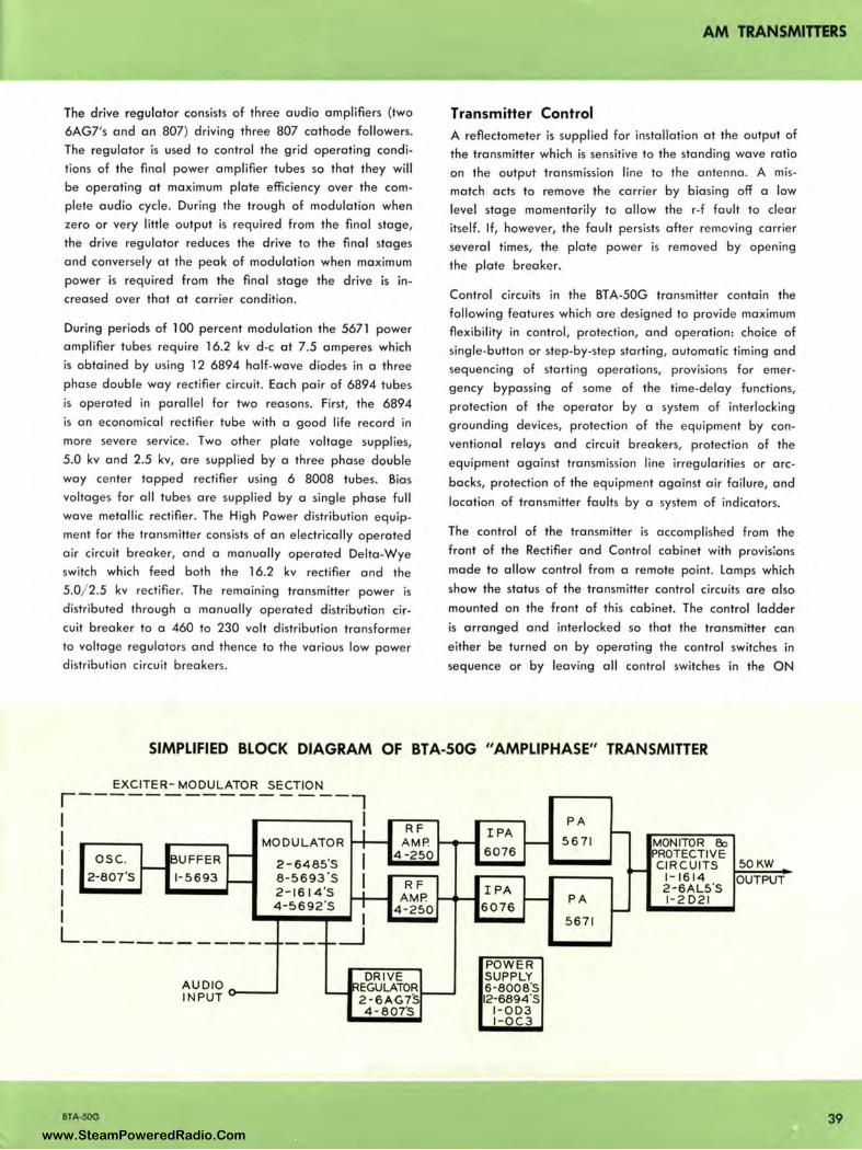
AM TRANSMITTERS
The drive regulator consists of three audio amplifiers (two
6AG7's and an 807) driving three 807 cathode followers.
The regulator is used to control the grid operating condi
tions of the final power amplifier tu bes so that they will
be operating at maximum plate efficiency over the com
plete audio cycle. During the trough of modulation when
zero or very little output is required from the final stage,
the drive regulator reduces the drive to the final stages
and conversely at the peak of modulation when maxim um
power is req uired from the final stage the drive is in
creased over that at carrier condition.
During periods of l 00 percent modu lation the 5671 power
amplifier tubes require 16.2 kv d-c at 7.5 amperes which
is obtained by using 12 6894 half-wave diodes in a three
phase do uble way rectifier circuit. Each pair of 6894 tubes
is operated in parallel for two reasons. First, the 6894
is an economical rectifier tube with a good life record in
more severe service . Two other plate voltage supplies,
5.0 kv and 2.5 kv, are supplied by a three phase double
way center tapped rectifier using 6 8008 tubes. Bias
voltages for all tubes are supplied by a single phase full
wave metallic rectifier. The High Power distribution equip
ment for the transmitter consists of an electrically operated
air circuit breaker, and a manually operated Delta-Wye
switch which feed both the 16.2 kv rectifier and the
5.0/ 2.5 kv rectifier. The remaining transmitter power is
distributed through a manually operated distribution cir
cuit breaker to a 460 to 230 volt distribution transformer
to voltage regulators and thence to the various low power
distribution circuit breakers.
Transmitter Control A reflectometer is supplied for installation at the output of
the transmitter which is sensitive to the standing wave ratio
on the output transmission line to the antenna . A mis
match acts to remove the carrier by biasing off a low
level stage momentarily to allow the r-f fault to clear
itself. If, however, the fault persists after removing carrier
several times, the plate power is removed by opening
the plate breaker.
Control circuits in the BTA-50G transmitter contain the
following features which are designed to provide maximum
flexi bility in control, protection, and operation: choice of
single-button or step-by-step starting , automatic timing and
sequencing of starting operations, provisions for emer
gency bypassing of some of the time-delay functions,
protection of the operator by a system of interlocking
grounding devices, protection of the equipment by con
ventional relays and circuit breakers, protection of the
equipment against transmission line irregularities or arc
backs, protection of the equipment against air failure, and
location of transmitter faults by a system of indicators.
The control of the transmitter is accomplished from the
fron t of the Rectifier and Control cabinet with provislons
made to allow control from a remote point. Lamps which
show the status of the transmitter control circuits are also
mounted on the front of this cabinet. The control ladder
is a rranged and interlocked so that the transmitter ca n
either be turned on by operating the control switches in
sequence or by leaving all control switches in the ON
SIMPLIFIED BLOCK DIAGRAM OF BTA-S0G "AMPLIPHASE" TRANSMITTER
EXCITER- MODULATOR SECTION
r I ---------------7
I 1 ·
I I I L
I MODULATOR ~
osc. - !BU FFER - 2 - 6485'S I 2-807 '$ 1- 5693 - 8 - 5693°S I
2 - 1614'$ H-4 - 5692'$ I
------ - ----~---_ _J
RF AM P.
4 -250
RF AMP.
4-250
AUDIO DR IVE
--
-- REGULATOR INPUT - 2-6AG7S -4 - 807'S
BTA·50G
PA IPA -- - 5 67 1 MONITOR 8o 6076 PROTECTI VE
CIRCUI TS 50KW - 1-1 6 14 OUTPUT IPA 2-6AL5'S - - PA 1-2 0 21 60 76 -5 671
POW E R SUPPLY 6-8008°S 12-6894'S
1- 003 I-OC 3
39 www.SteamPoweredRadio.Com
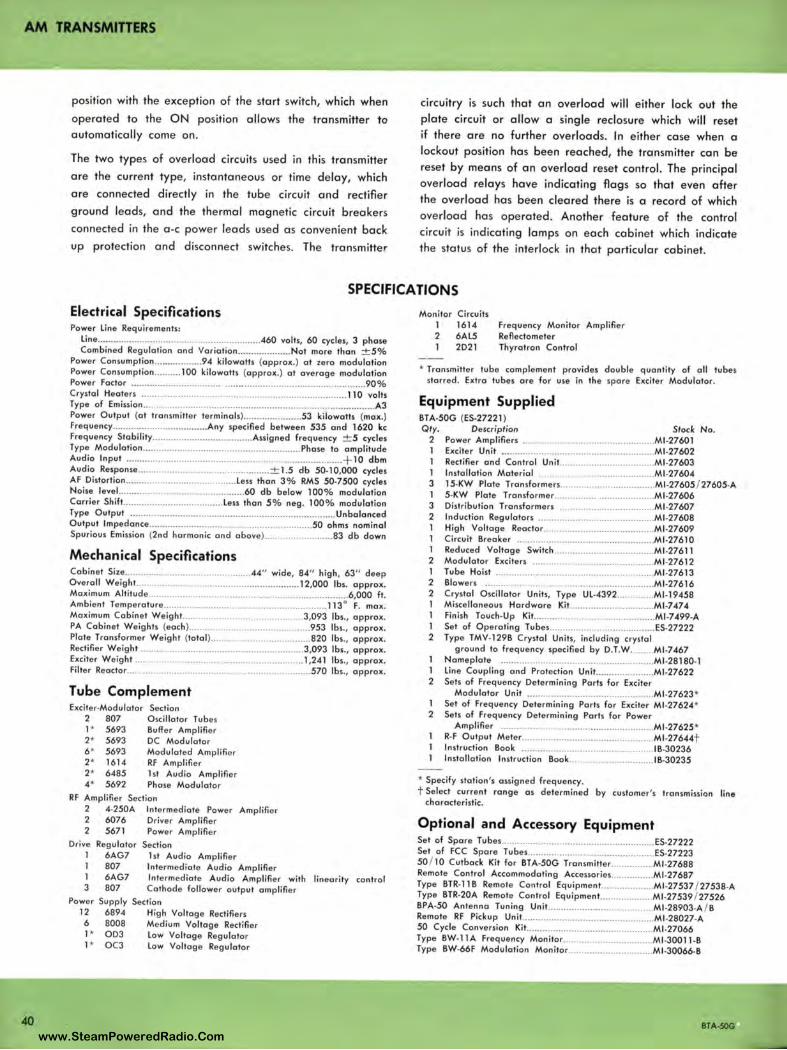
AM TRANSMITTERS
position with the exception of the start switch, which when operated to the O N position allows the transmitter to automatically come on.
The two types of overloa d circuits used in this transmitter are the current type, instantaneous or time delay, which are connected directly in the tube circuit a nd rectifier g round leads, and the therma l magnetic circuit breakers connected in the a -c power leads used as convenient back up protection and disconnect switches. The transmitter
circuit ry is such that an overload wi ll either lock out the plate circuit or allow a single reclosure which will reset if there are no fur ther overloa ds. In either ca se when a lockout position has been rea ched, the tra nsmitte r can be reset by mea ns of an overloa d reset control. The principa l overload relays have ind icating fl a gs so that even a fter the overload has been clea red there is a record of which overload has opera ted. Another feature of the control circuit is indicating lamps on each ca binet which indicate the status of the interlock in that particu lar cabinet.
SPECIFICATIONS
Electrical Specifications Power Line Requirements:
line .................... ...... ... ................. .. ..... ... ... .. .460 volts, 60 cycles, 3 phase Combined Regulation and Voriotion ......... ........... Not more than ± 5%
Power Consumption ............. ..... 94 kilowatts (approx.) al zero modulation Power Consumption ..... ..... l 00 kilowatts (approx.) al overage modulation Power Factor .. ...... ... ... .. .. ...... .......... ... .... .... .. .......... .. .. ........... ... .. ......... . 90% Crystal Heaters .................... .. ... .. ........ ....................... ................... . 110 volts Type of Emission ....... ......... ...... .. .. ......... .... ...... .. .. ....... .. .............................. A3 Power Output (al transmitter terminols) ....... .. .. ........... 53 kilowatts (max.) Frequency ............... ..... .. .............. Any specified between 535 and 1620 kc Frequency Stobility .................... ....... ..... ...... Assigned frequency ± 5 cycles Type Modulotion ...................... ............. ..... .... ..... ........... Phose lo amplitude Audio Input ... ..... ......................................... .... ...... ... .................... + l O dbm Audio Response .. .............................................. ± 1.5 db 50• l 0,000 cycles AF Distortion ........................................ . Less than 3% RMS 50•7500 cycles Noise level.. ....... ...................................... . 60 db below 100% modulation Carrier Shift. ................................. .... Less than 5% neg . 100% modulation Type Output ........... ... .... .. ... ...... ................... .............................. Unbalanced Output lmpedonce .... ......... ............ ... .. ......... .... ... ........ ... ... .. 50 ohms nominal Spurious Emission (2nd harmonic and obove) ..... ................... 83 db down
Mechanical Specifications Cabinet Size .......... ...................................... 44" wide, 84" high, 63" deep Overall Weight .. ................................................. ......... 12,000 lbs. approx . Maximum Altitude......... . ............................. ..... .... ........ ............ 6,000 ft . Ambient Temperature ........... .............................. .. .... ........ ... 113° F. max. Maximum Cabinet Weight.. ......................................... 3,093 lbs., approx. PA Cabinet Weights (each) ... ... ......................... .......... .. 953 lbs., approx. Plate Transformer Weight (total) ............ ......................... 820 lbs., approx. Rectifier Weight ..................................................... ......... 3,093 lbs., approx. Exciter Weight ................... ....... ............. ................ ....... 1,241 lbs., approx. Filter Reactor ..... ........... .... . ................................... ..... .. . 570 lbs., approx.
Tube Complement Exciter•Modulotor Section
2 807 Oscillator Tubes l * 5693 Buffer Amplifier 2* 5693 DC Modulator 6* 5693 Modulated Amplifier 2* 1614 RF Amplifier 2* 6485 l st Audio Amplifier 4* 5692 Phase Modulator
RF Amplifier Section 2 4•250A Intermediate Power Amplifi er 2 6076 Driver Amplifier 2 5671 Power Amplifi er
Drive 1 l l 3
Regulator 6AG7 807 6AG7 807
Section l st Audio Amplifier Intermediate Audio Amplifier Intermediate Audio Amplifier with Cathode follower output amplifier
Power Supply Section 12 6894 High Voltage Rectifiers 6 8008 Medium Voltage Rectifier l * OD3 Low Voltage Regulator l * OC3 Low Voltage Regulator
linearity control
Monitor Circuits l 1614 2 6AL5 l 2021
Frequency Monitor Amplifier Refleclomeler Thyratron Control
• Transmitter tube complement provides double quantity of all tubes starred . Extra tubes ore for use in the spore Exciter Modulator.
Equipment Supplied BTA•50G (ES.27221) Qty. Description Stock No.
2 Power Amplifiers ........................... ..... ................ .. Ml.27601 l Exciter Unit ........... ............. .. ............. .. .. .... ........... Ml•27602 l Rectifier and Control Unit... ............ .. ................. .. Ml.27603 l Installation Material ............................................ Ml .27604 3 l5•KW Plate Tronsformers ........... .... ..... ................ Ml •27605 / 27605·A l 5•KW Plate Tronsformer .................................... . Ml .27606 3 Distribution Transformers .. .................................. Ml•27607 2 Induction Regulotors ........... ..... ............................ Ml •27608 l High Voltage Reoclor ...... ..................... .. ....... .. .... Ml •27609 l Circuit Breaker ................. ........ .... ... .................... Ml •27610 l Reduced Voltage Switch ....... ............ ....... ............ Ml•276 l l 2 Modulator Exciters ............................................. . Ml•276 l 2 l Tube Hoist ........................ .............. ...................... Ml •27613 2 Blowers ... ... .. .... ........ ....................... ...... ............... Ml •27616 2 Crystal Oscillator Units, Type UL.4392 ............ .. Ml• l 9458 l Miscellaneous Hardware Kit .......... ................... ... Ml-7474 l Finish Touch•Up Kit ........................... ................... Ml.7499-A l Set of Operating Tubes ............. ................... .. ..... . ES.27222 2 Type TMV. 129B Crystal Units, including crystal
ground to frequency specified by D.T.W ....... .. Ml•7467 Nameplate ........ ... .. ..... ....... .... .. ... ...... ........ ..... ..... Ml.28180•1
l Line Coupling and Protection Unil ...................... Ml•27622 2 Sets of Frequency Determining Paris for Exciter
Modulator Unit ............... ................................. Ml •27623* l Set of Frequency Determining Ports for Exciter Ml•27624* 2 Sets of Frequency Determining Paris for Power
Amplifier ........... ....................... ........................ Ml •27625* R· F Output Meter ............ .............. ... .. ... ...... .......... Ml•27644t Instruction Book ................................................. 18•30236 Installation Instruction Book .................. ............. .lB·30235
• Specify station 's assigned frequency . t Select current range as determined by customer's transmission line
characteristic.
Optional and Accessory Equipment Set of Spore Tubes ... .. ...... ............... .. ..... ... .... .... .. ..... .. .... . ES•27222 Set of FCC Spore Tubes .... .............. ... ....... .. ... ..... ......... ES•27223 50 / 10 Cutback Kit for BTA•50G Tronsmitter ...... ...... .... Ml .27688 Remote Control Accommodating Accessories ............ .... Ml •27687 Type BTR· 11 B Remote Control Equipment ... ................. Ml •27537 / 27538.A Type BTR·20A Remote Control Equipmenl ............. ....... Ml.27539 / 27526 BPA·50 Antenna Tuning Unit ........... .... ........................ . Ml •28903·A/ B Remote RF Pickup Unit ......... ..... ......... ....... .................... Ml •28027•A 50 Cycle Conversion Kit .................. ...... .... .................... Ml •27066 Type BW. l lA Frequency Monitor .................... .... .......... Ml •300 l l•B Type 8W•66F Modulation Monitor ...... ...... .................... Ml •30066-B
BTA-50G www.SteamPoweredRadio.Com
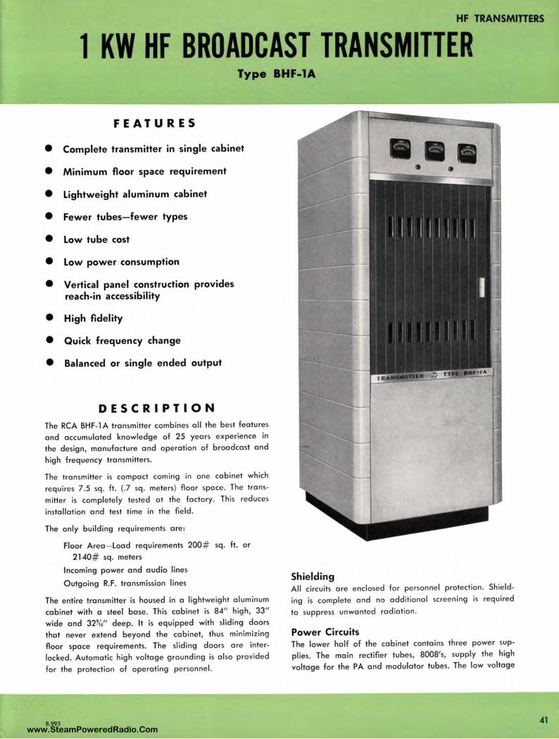
HF TRANSMITIERS
l KW HF BROADCAST TRANSMITTER Type BHF-1A
FEATURES
• Complete transmitter in single cabinet
• Minimum floor space requirement
• Lightweight aluminum cabinet
• Fewer tubes- fewer types
• Low tube cost
• Low power consumption
• Vertical panel construction provides reach-in accessibility
• High fidelity
• Quick frequency change
• Balanced or single ended output
DESCRIPTION
The RCA BHF-1 A transmitter combines all the best features
and a ccumulated knowledge of 25 years experience in
the design, man ufacture and operation of broadcast and
high freq uency tra nsmitters.
The transmitter is compact coming in one cabinet which
requires 7.5 sq. ft. (.7 sq. meters) floor space. The trans
mitter is completely tested at the factory. This reduces
installation and test time in the field.
The only building requirements are:
Floor Area- Load requirements 200# sq. ft. or
2 140 # sq. meters
Incoming power and audio lines
O utgoing R.F. transmission lines
The entire tra nsmitter is housed in a lightweight aluminum
ca binet with a steel base. This cabinet is 84" high, 33"
wide a nd 32~6'' deep. It is equipped with sliding doors
that never extend beyond the cabinet, thus minimizing
fl oor space requirements. The sliding doors are inter
locked. Automatic high voltage grounding is also provided
for the protection of operating personnel.
B.993
Shielding All circuits are enclosed for personnel protection . Shield
ing is complete and no additional screening is required
to suppress unwanted radiation .
Power Circuits The lower half of the cabinet contains three power sup
plies. The main rectifier tubes, 8008's, supply the high
voltage for the PA and modulator tubes. The low voltage
41 www.SteamPoweredRadio.Com
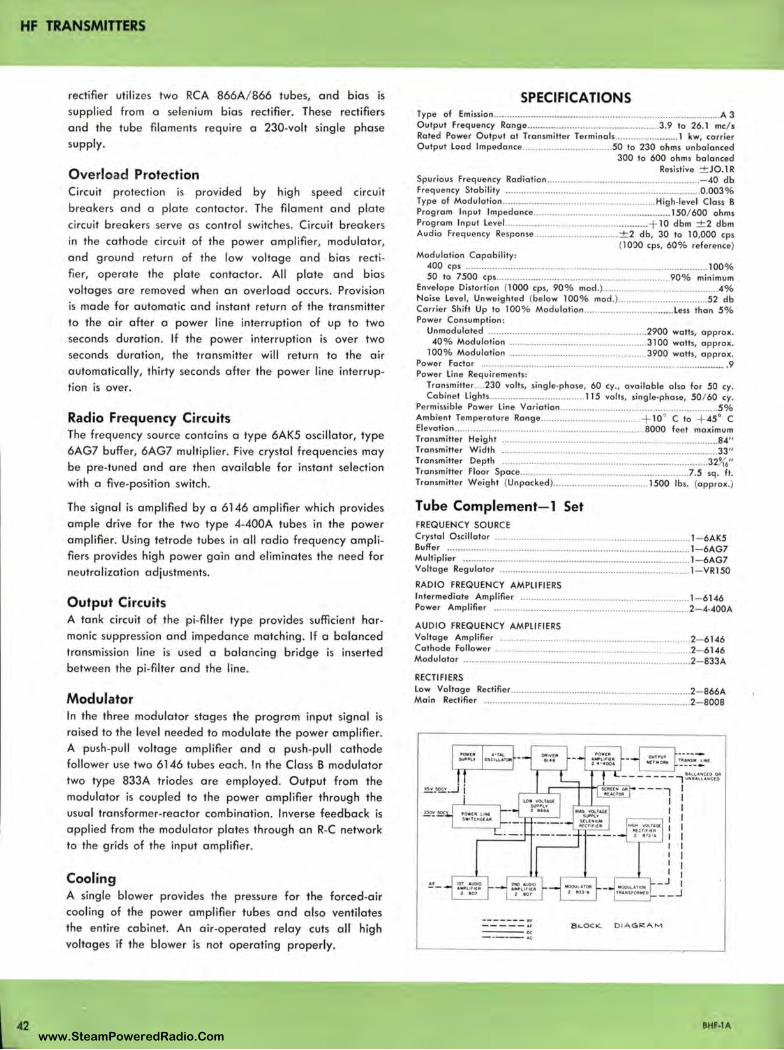
HF TRANSMITTERS
42
rectifier utilizes two RCA 866A/ 866 tubes, and bias is supplied from a selenium bias rectifier. These rectifiers and the tube filaments require a 230-volt single phase supply.
Overload Protection Circuit protection is provided by high speed circuit breake rs and a plate contactor. The filament and plate circuit breake rs se rve a s control switches. Circuit breakers in the cathode circuit of the power amplifier, modulator, and ground return of the low voltage and bias rectifier , ope rate the plate contactor. All plate and bias voltages are removed when an overload occurs. Provision is made for automatic and instant return of the transmitter to the air after a power line interruption of up to two seconds duration . If the power interruption is over two seconds duration, the transmitter will return to the air automatically, thirty seconds after the power line interruption is over.
Radio Frequency Circuits The frequency source contains a type 6AK5 oscillator, type 6AG7 buffer, 6AG7 multiplie r. Five crystal frequencies may be pre-tuned and are then available for instant selection with a five-position switch.
The signal is amplified by a 6146 amplifier which provides ample dr ive for the two type 4-400A tubes in the power amplifier. Using tetrode tubes in all radio frequency amplifiers provides high power gain and eliminates the need for neutralization adjustments.
Output Circuits A tank circuit of the pi-filter type provides sufficient harmonic suppression and impedance matching. If a balanced transmission line is used a balancing bridge is inserted betwee n the pi-filter and the line.
Modulator In the three modulator stages the program input signal is raised to the level needed to modulate the power amplifier. A push-pull voltage amplifier and a push-pull cathode follower use two 6146 tubes each. In the Class B modulator two type 833A triodes are employed. Output from the modulator is coupled to the power amplifier through the usual transformer-reactor combination. Inverse feedback is applied from the modulator plates through an R-C network to the grids of the input amplifier.
Cooling A single blower provides the pressure for the forced -air cooling of the power amplifier tubes and also ventilates the entire cabinet. An air-operated relay cuts all high voltages if the blower is not operating properly.
SPECIFICATIONS Type of Em ission ....... .... ......................................... ... .................. ............. A 3 Output Frequency Ronge ....................... ......... ........... ....... 3.9 to 26.1 mc/ s Rated Powe r Output at Transm itte r Terminol s ............... ......... 1 kw, ca rrier Output lood lmpedonce .......... ........................ 50 to 230 ohms unbalanced
300 to 600 ohms balanced Resistive ± JO.1 R
Spu rious Freq ue ncy Radiation .. ................... ..................................... - 40 db f requency Stabi lity .. ............... ... ...................................................... 0 .003% Type of Modu la tion ............ .. ............................................ High-leve l Class B Prog ra m Input lmpedance .................................. ............ ..... . 150/ 600 ohms Program Input l evel.. .. ... ......................................... ...... + 10 dbm ± 2 dbm Audio Frequ ency Res ponse ................................ ± 2 db, 30 to 10,000 cps
(1000 cps, 60 % reference) Modulation Capability:
400 cps ............................................................................................ 100% 50 ta 7500 cps ...................... ... .. .. ... .. ................................ 90% mi nimum
Enve lope Distort ion (1000 cps, 90% mod .) ............................................ 4% Noise l evel, Unwe ighted (be low 100% mod.) ............ ...................... 52 db Carr ier Shift Up to 100% Modulation ........................ .......... l ess than 5% Powe r Consumption :
Unmodulated ............................................................ 2900 watts, a pprox. 40 % Modulation .................................................... 3100 watts, app rox.
100% Modulation .................................................... 3900 watts, a pprox. Power Factor ..................................................... ....................................... . 9 Power Lin e Requirements:
Transmitter .... 230 volts, single•phase, 60 cy., ava ilable al so fo r 50 cy. Cabinet lights .. ........... ....................... 115 volts, sing le-phase, 50/ 60 cy.
Permi ss ible Power line Variation .................................. .......................... 5% Ambient Tempe ratu re Range ...................................... + 10• C to + 45° C El evation ........................................... .. ........................... 8000 feet ma ximum Transmitter He ight .................... .......... .................................................... 84" Transmitte r Width .................................................................................. 33" Transmitter De pth .............................................................................. 321{6" Transmitter Floor Space .................................... ........................... .7 .5 sq . ft . Transmitter We ight (Unpacked) ....... ................ .. ........... 1500 lbs. (app rox.)
Tube Complement- 1 Set FREQUENCY SOURCE Crystal Oscillator ......................................................................... 1- 6AK5 Buffer ...... .... ......... ... ........................................................ ....... ....... 1- 6AG7 Multiplier ................................................ ................................ ...... 1- 6AG7 Voltage Regulato r .............. ................................................. ......... 1- VRl 50
RADIO FREQUENCY AMPLIFIERS Inte rmediate Amplifier ............................................................... 1- 6146 Powe r Ampl ifier ............ ...... .. ... .. ..... ............................................ 2- 4•400A
AUDIO FREQUENCY AMPLIFIERS Voltage Amplifier ....................................................................... 2- 6146 Cathode Follower ............................................... .......................... 2- 6146 Modulator .................................... ....................... ........................... 2- 833A
RECTIFIERS low Voltage Rectifie r ................ ............. ....................................... 2- 866A Main Rect ifi er .. ............................................................................ 2- 8008
------- ,., _____ ,., DC
- ---- AC
B LOCK. 0IAG~AM
BHF-lA
www.SteamPoweredRadio.Com
wigfi
Stolen 2 Line Transparent
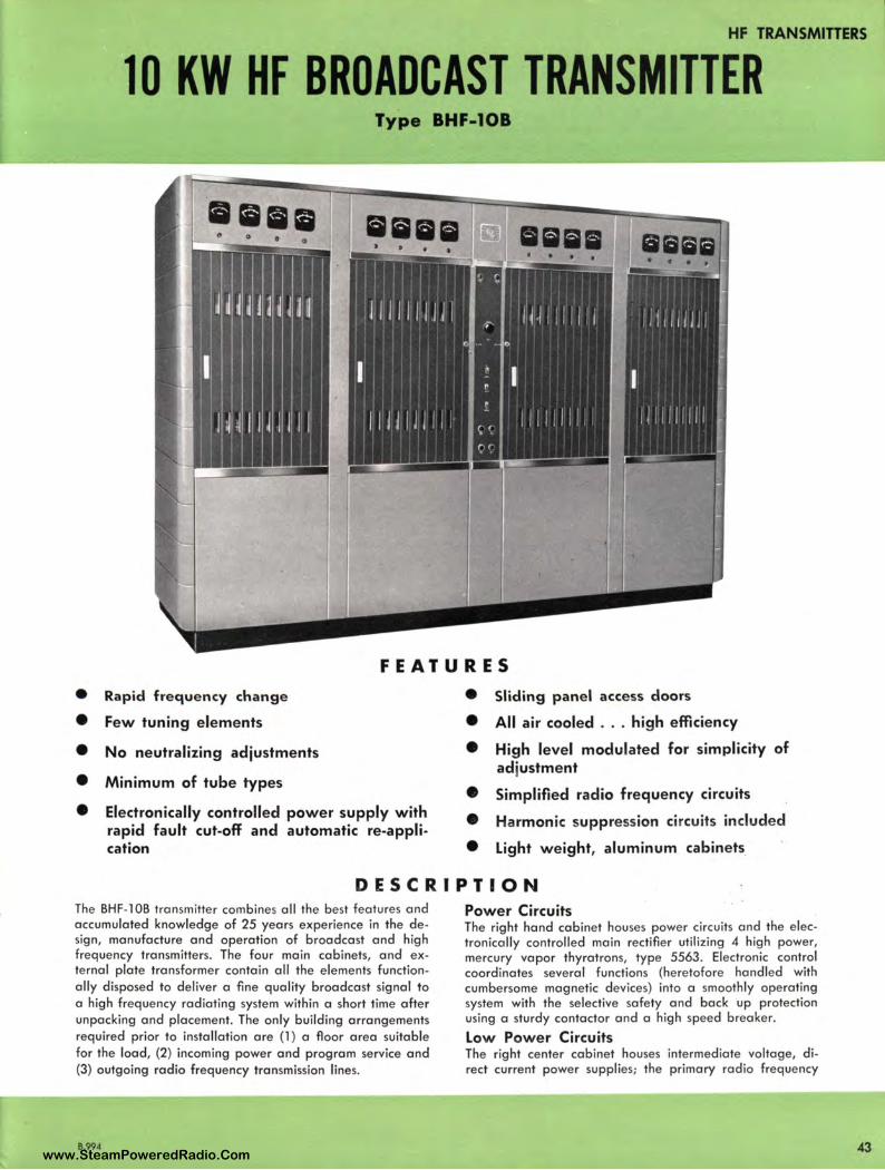
HF TRANSMITTERS
10 KW HF BROADCAST TRANSMITTER Type BHF-10B
FEATURES
• Rapid frequency change • Sliding panel access doors
• Few tuning elements • All air cooled ... high efficiency
• No neutralizing adjustments • High level mod ulated for simpl icity of
• Minimum of tube types ad justment
• Simplified radio frequency ci rcuits
• Electronically controlled power supply with • Harmonic suppression circuits included rapid fault cut-off and automatic re-appli-cation • Light weight, aluminum cabinets
DESCRIPTION The BHF-1 OB transmitter combines all the best features and accumulated knowledge of 25 years experience in the design, manufacture and operation of broadcast and high frequency transmitters. The four main cabinets, and external plate transformer contain all the elements functionally disposed to deliver a fine quality broadcast signal to a high frequency radiating system within a short time after unpacking and placement. The only building arrangements required prior to installation are (1) a floor area suitable for the load, (2) incoming power and program service and (3) outgoing radio frequency transmission lines.
B.994
Power Circuits The right hand cabinet houses power circuits and the electronically controlled main rectifier utilizing 4 high power, mercury vapor thyratrons, type 5563. Electronic control coordinates several functions (heretofore handled with cumbersome magnetic devices) into a smoothly operating system with the selective safety and back up protection using a sturdy contactor and a high speed breaker.
Low Power Circuits The right center cabinet houses intermediate voltage, direct current power supplies; the primary radio frequency
www.SteamPoweredRadio.Com
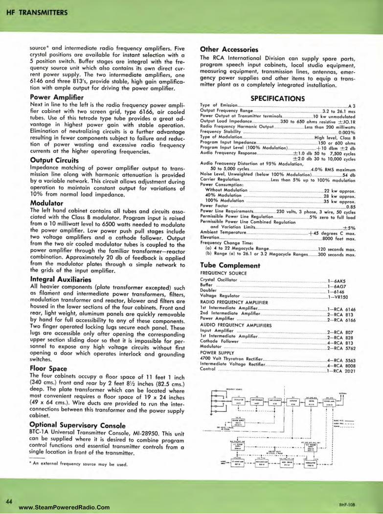
HF TRANSMITTERS
source* and intermediate radio frequency amplifiers. Five crystal positions are available for instant selection with a 5 position switch. Buffer stages are integral with the frequency source unit which also contains its own direct current power supply. The two intermediate amplifiers, one 6146 and three 813's, provide stable, high gain amplification with ample output for driving the power amplifier.
Power Amplifier Next in line to the left is the radio frequency power amplifier cabinet with two screen grid, type 6166, air cooled tubes. Use of this tetrode type tube provides a great advantage in highest power gain with stable operation. Elimination of neutralizing circuits is a further advantage resulting in fewer components subject to failure and reduction of power wasting and excessive radio frequency currents at the higher operating frequencies.
Output Circuits Impedance matching of power amplifier output to transmission line along with harmonic attenuation is provided by a variable network. This circuit allows adjustment during operation to maintain constant output for variations of l 0% from normal load impedance.
Modulator The left hand cabinet contains all tubes and circuits associated with the Class B modulator. Program input is raised from a l O milliwatt level to 6500 watts needed to modulate the power amplifier. Low power push pull stages include two voltage amplifiers and a cathode follower. Output from the two air cooled modulator tubes is coupled to the power amplifier through the familiar transformer- reactor combination. Approximately 20 db of feedback is applied from the modulator plates through a simple network to the grids of the input amplifier.
Integral Auxiliaries All heavier components (plate transformer excepted) such as filament and intermediate power transformers, filters, modulation transformer and reactor, blower and filters are housed in the lower sections of the four cabinets. Front and rear, light weight, aluminum panels are quickly removable by hand for full accessibility to any of these components. Two finger operated locking lugs secure each panel. These lugs are accessible only after opening the corresponding upper section sliding door so that it is impossible for personnel to expose any high voltage circuits without first opening a door which operates interlock and grounding switches.
Floor Space The four cabinets occupy a floor space of 11 feet l inch (340 ems.) front and rear by 2 feet 8½ inches (82.5 ems.) deep. The plate transformer which can be located where most convenient requires a floor space of 19 x 24 inches (49 x 64 ems.). Wire ducts are provided to run the interconnections between this transformer and the power supply cabinet.
Optional Supervisory Console BTC-1 A Universal Transmitter Console, Ml -28950. This unit can be supplied where it is desired to combine program control functions and essential transmitter controls from a single location in front of the transmitter.
• An externa l frequency source may be used.
Other Accessories The RCA International Division can supply spare parts, program speech input cabinets, local studio equipment, measuring equipment, transmission lines, antennas, emergency power supplies and other items to equip a transmitter plant as a completely integrated installation.
SPECIFICATIONS Type of Emissian ...................................................................................... A 3 Output Frequency Range ..... ......... ...................... .............. .. .. 3 .2 ta 26.1 mes Power Output at Transmitter terminals ........................ 10 kw unmodulated Output load lmpedance ............ ..... ..... 350 ta 650 ohms resistive ± JO.1 R Radio Frequency Harmonic Output ........ ................ less than 200 milliwatts Frequency Stability .................. .................. .. ....... ...... ......... ......... ..... 0 .003 % Type of Modulation ......... .. .......... ....... ............... ..... ........ High level, Class B Program Input Impedance ................................................ I 50 or 600 ohms Program Input level (100% Modulation) ...................... + 10 dbm ± 2 db Audio Frequency Response ............................ ± 1.0 db 50 to 7,500 cycles
± 2.0 db 30 to 10,000 cycles Audio Frequency Distortion at 95% Modulation,
50 to 5,000 cycles ... .. .............. ...... .............. ... ..... .4.0 % RMS maximum Noise level, Unweighted (below 100% Modulation ) .... .................... 54 db Carrier Regulation .. ..... .. ...... .. ....... l ess than 5% up to 100% modulation Power Consumption :
Without Modulation .......................................................... 22 kw approx. 40% Modulation ... ............. .... ....... ................................... 28 kw approx. 100% Modulation ........................... ...................... .... ....... 35 kw approx.
Power Factor ..... .......... ..... .. ....... ............ ....................... ................. .. ....... 0 .85 Power line Requirements ..... .... .. ....... 230 volts, 3 phase, 3 wire, 50 cycles Permissible Power line Regulation ............................ 5% zero to full load Permissible Power line Combined Regulation
and Variation limits ...................................... ....... ....................... ± 5% Ambient Temperature .................................... ............ + 45 degrees C max. Elevation ............. .... ....... .......................................... ........... ... 8000 feet max. Frequency Change Time:
(a ) 4 to 22 Megacycle Range ....... ...... ......................... 120 seconds max. (b) Range (a ) ta 26.1 or 3.2 Megacycle Ranges ........ 300 seconds max.
Tube Complement FREQUENCY SOURCE Crystal Oscillator ..... .................. ................................ .. ........... 1- 6AK5 Buffer ........... .......... ............................ .. ................... ................ 1- 6AG7 Doubler ............................. .......................... ...... .................... 1- 6146 Voltage Regulator .......... .......... .............................................. 1- VR150 RADIO FREQUENCY AMPLIFIER 1st Intermediate Amplifier ...................................................... 1- RCA 6146 2nd Intermediate Amplifier ............ ........................................ 2- RCA 813 Power Amplifier ...................................................................... 2- RCA 6166 AUDIO FREQUENCY AMPLIFIERS Input Ampl ifier .................... .... ................................. ............. 2- RCA 807 1st Intermediate Amplifier ................ ..... ................................. 2- RCA 828 Cathode Follower ................................................................. .4- RCA 813 Modulator ...................................... .. ............... ........................ 2- RCA 5762 POWER SUPPLY 4700 Volt Thyratron Rectifier .... .......... ............. ...................... .4- RCA 5563 Intermediate Voltage Rectifier ............................................... .4- RCA 8008 Control ....... ................. ................. ... ........................................ 1- RCA 2D21
.i~ ....... !.. ..... t : :::::; ' ,-~······· -· .. ······; J'
·- · ---=~~ ·-·-----·
I ' ' ' :::::-:-:: 1---------,
' ' ' '
r~~;:::.·.·~·:.·::~_-_··::~·:::·_·~·.·::~~~r-•1 ffi-
J.:.·-- .• ·-§-·;~•.:.-~~'.~ .. :,.t;.;;.· • · -~:. i... ! - - - --- --- - - ~-- -'Cit -- _ _,J -,i •N<11~ .,-, ,_ -
BHF-108 www.SteamPoweredRadio.Com
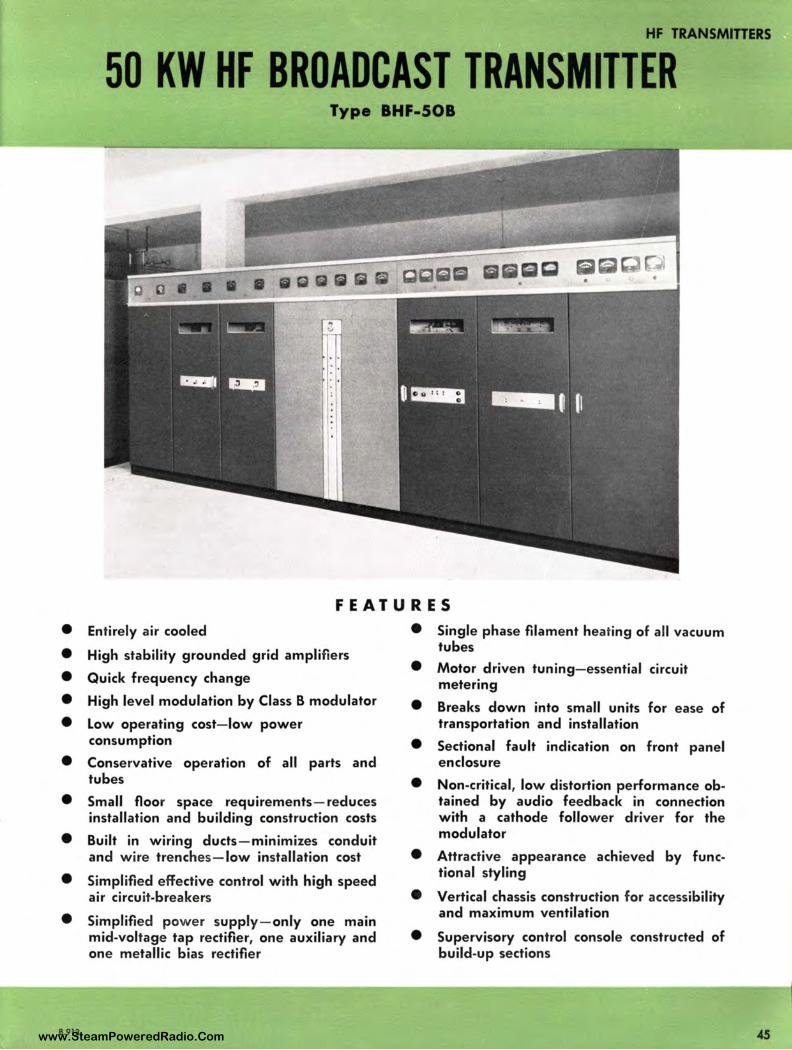
HF TRANSMITTERS
50 KW HF BROADCAST TRANSMITTER Type BHF-508
FEATURES
• Entirely air cooled
• High stability grounded grid amplifiers
• Quick frequency change
• High level modulation by Class B modulator
• Low operating cost-low power consumption
• Conservative operation of all parts and tubes
• Small floor space requirements-reduces installation and building construction costs
• Built in wiring ducts-minimizes conduit and wire trenches-low installation cost
• Simplified effective control with high speed air circuit-breakers
• Simplified power supply-only one main mid-voltage tap rectifier, one auxiliary and one metallic bias rectifier
B.913
• Single phase filament heating of all vacuum tubes
• Motor driven tuning-essential circuit metering
• Breaks down into small units for ease of transportation and installation
• Sectional fault indication on front panel enclosure
• Non-critical, low distortion performance obtained by audio feedback in connection with a cathode follower driver for the modulator
• Attractive appearance achieved by functional styling
• Vertical chassis construction for accessibility and maximum ventilation
• Supervisory control console constructed of build-up sections
www.SteamPoweredRadio.Com
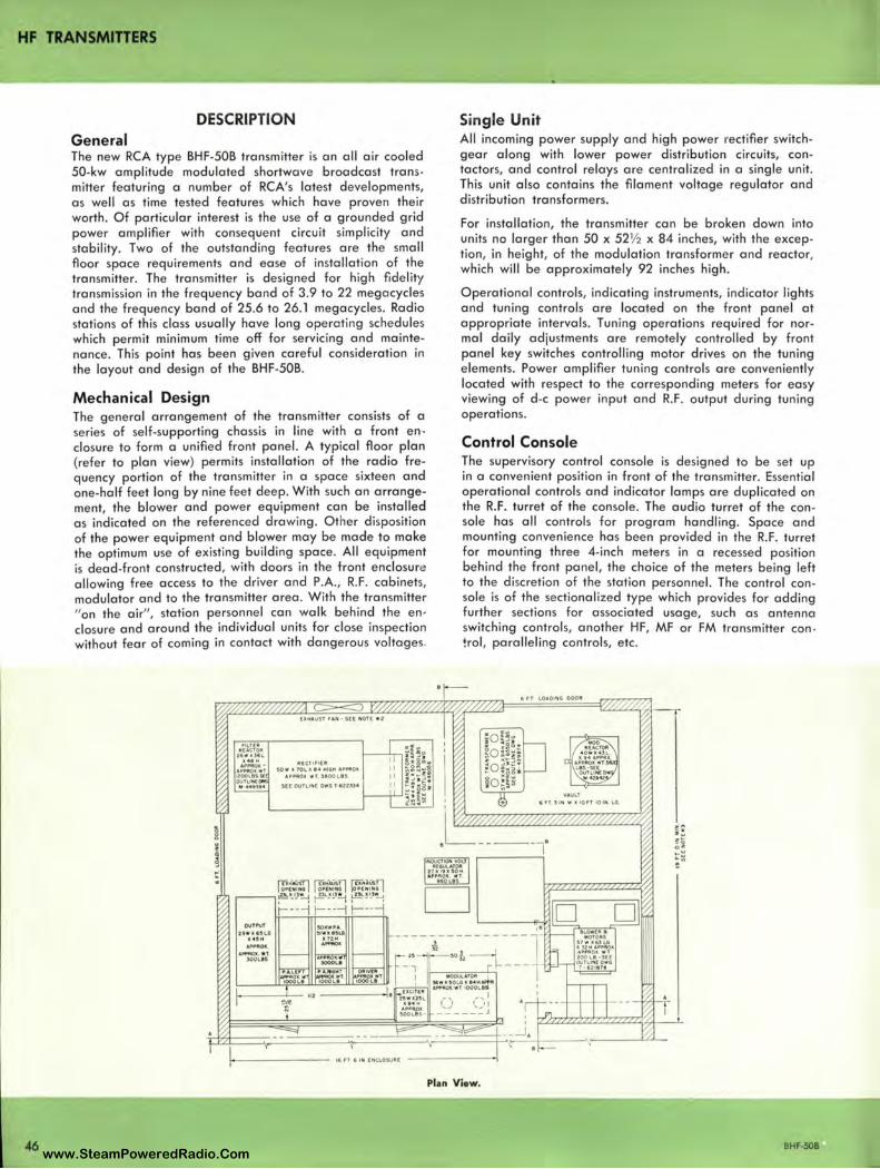
HF TRANSMITTERS
DESCRIPTION General The new RCA type BHF-50B transmitter is an all air cooled 50-kw amplitude modulated shortwave broadcast transmitter featuring a number of RCA's latest developments, as well as time tested features which have proven thei r worth. Of particular interest is the use of a grounded grid power amplifier with consequent circuit simplicity and stability. Two of the outstanding features are the small floor space requirements and ease of installation of the transmitter. The transmitter is designed for high fidelity transmission in the frequency band of 3.9 to 22 megacycles and the frequency band of 25.6 to 26. l megacycles. Radio stations of this class usually have long operating schedu les which permit minimum time off for servicing and maintenance. This point has been given careful consideration in the layout and design of the BHF-50B.
Mechanical Design The general arrangement of the transmitter consists of a se ries of self-supporting chassis in line with a front enclosure to form a unified front panel. A typical floor plan (refer to plan view) permits installation of the radio frequency portion of the transmitter in a space sixteen and one-half feet long by nine feet deep. With such an arrangement, the blower and power equipment can be installed as indicated on the referenced drawing . Other disposition of the power equipment and blower may be made to make the optimum use of existing building space. All equipment is dead-front constructed, with doors in the front enclosure allowing free access to the driver and P.A., R.F. cabinets, modulator and to the transmitter area. With the transmitter "on the air", station personnel can walk behind the en, closure and around the individual units for close inspection without fear of coming in contact with dangerous voltages.
[ll;MAUST ,.AN· SEE NOH: • 2
A(CTl,1( 11 SOW• l'Ol.l 14 MIGtt APPftOlC
APPMOlC WT, 39001.IIS
S(E OUTLINE D~G T U23l4
Single Unit All incoming power supply and high power rectifier switchgear along with lower power distribution circuits, contactors, and control relays are centralized in a single unit. This unit also contains the filament voltage regulator and distribution transformers.
For installation, the transmitter can be broken down into units no larger than 50 x 52½ x 84 inches, with the exception, in height, of the modulation transformer and reactor, which will be approximately 92 inches high.
Operational controls, indicating instruments, indicator lights and tuning controls are located on the front panel at appropriate intervals. Tuning operations required for normal daily adjustments are remotely controlled by front panel key switches controlling motor drives on the tuning elements. Power amplifier tuning controls are conveniently located with respect to the corresponding meters for easy viewing of d-c power input and R.F. output during tuning operations.
Control Console The supervisory control console is designed to be set up in a convenient position in front of the transmitter. Essential operational controls and indicator lamps are duplicated on the R.F. turret of the console. The audio turret of the console has all controls for program handling. Space and mounting convenience has been provided in the R.F. turret for mounting three 4-inch meters in a recessed position behind the front panel, the choice of the meters being left to the discretion of the station personnel. The control console is of the sectionalized type which provides for adding further sections for associated usage, such as antenna switching controls, another HF, MF or FM transmitter con !rol, paralleling controls, etc.
•-
NOVCTION V0LJ ll(GUlATOII
!7l 19X SOH .._ PPA OX WT,
K L&S
6 rT t.OAOING 00011
VAULT fiHllNWll tO fflOIN LG
rr,::irn rn~::sJi w::~n i!:!:•})~ d._~.lC~l !.J L.!!!-_!':_l~
~---l f-·---i f--·-i D • • OUTll'UT 501CWPA ~I .. I SUI
1(72.H ·-·
,an GI N (NCLOSUlllf
Plan View.
BHF-508 www.SteamPoweredRadio.Com
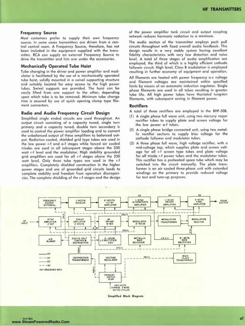
HF TRANSMITTERS
Frequency Source Most customers prefer to supply their own frequency source. In some cases transmitters are driven from a central control room. A Frequency Source, therefore, has not been included in the equipment supplied with the transmitter. RCA can supply an external Frequency Source to drive the transmitter and lists one under the accessories.
Mechanically Operated Tube Hoist Tube changing in the driver and power amplifier and modulator is facilitated by the use of a mechanically operated tube hoist, solidly mounted in a swivel supporting structure and suitably located for easy access to the high power tubes. Swivel supports are provided. The hoist can be easily lifted from one support to the other, depending upon which tube is to be removed. Minimum tube change time is assured by use of quick opening clamp type filament connectors.
Radio and Audio Frequency Circuit Design Simplified single ended circuits are used throughout. An output circuit consisting of a capacity tuned, single turn primary and a capacity tuned, double turn secondary is used to control the power amplifier loading and to convert the unbalanced output of these amplifiers to balanced output. Radiation cooled, shielded grid type tubes are used in the low power r-f and a-f stages while forced air cooled triodes are used in all subsequent stages above the 250 watt r-f level and the modulator. High stability grounded grid amplifiers are used for all r-f stages above the 250 watt level. Only three tube types are used in the r-f amplifiers. Completely shielded construction in the higher power stages and use of grounded grid circuits leads to complete stability and freedom from operation discrepancies. The complete shielding of the r-f stages and the design
AF INPUT
AIR BLOWER
l - 4 E27A DOUBLER
23cYll5 VOLT CONTROL&
DISTIIIBUTION
2- 4E27A I ST RF
AMPLIFIER
AF DRIVER 8 - 813
2 - 8008 LP.RECTIFIER
ZKV
of the power amplifier tank circuit and output coupling network reduces harmonic radiation to a minimum .
The audio section of the transmitter employs push pull circuits throughout with fixed overall audio feedback. This design results in a very stable system having excellent fidelity characteristics with very low distortion and noise level. A total of three stages of audio amplification are employed, the third of which is a highly efficient cathode follower circuit. High level, Class B modulation is employed resulting in further economy of equipment and operation .
All filaments are heated with power frequency a -c voltage and filament voltages are maintained within specified limits by means of an automatic induction regulator. Single phase filaments are used in all tubes resulting in greater tube life. All high power tubes have thoriated tungsten filaments, with subsequent saving in filament power.
Rectifiers A total of three rectifiers are employed in the BHF-50B.
(1 ) A single phase full wave unit, using two mercury vapor rectifier tubes to supply plate and screen voltage for the low power a -f tubes.
(2) A single phase bridge connected unit, using two metallic rectifier sections to supply bias voltage for the cathode follower and modulator tubes.
(3) A three phase full wave, high voltage rectifier, with a mid-voltage tap, which supplies plate and screen voltage for all r-f screen type tubes and plate voltage for all triode r-f power tubes and the modulator tubes. This rectifier has a preheated spare tube which may be switched into the circuit manually. The plate transformer is an air cooled three-phase unit with extended windings on the primary to provide reduced voltage for test and tune-up purposes.
GG
1- 5762 INTERMEDIATE
AMPLIFIER
MODULATOR 2-9C25
METALLIC BIAS
RECTIFIER
GG
I - 9C25 ORIVER
AMPLIFI ER
I
- -..1.-------- -MODULATION
TRANSFORMER
4.5 K.V. 6- 8578 MAIN
RECTIFIER
GG
2 · 9C25 50~W FINAL OUTPUT AMPLIFIER
I _..,
MODULATION REACTOR
"' ' ~ I
L ______ 2 30V. _____ L ____________ J
--RF
-· -AF
- - DC
- - - AC
GG• GROUNDED GRID
BHF-'OB
N
DISTRIBUTION TRANSFORM£ R
460 V VOLTAGE REGUL ATOR r----------- - - -
PRIMARY SWITCH
GEAR
1 I
I ·1
I ..J
I 460VOLTS I 3 PHASE 3 WIRE
50 /60 CYCLES
Simplified Block Diagram.
MAI N PL ATE
TRANSFORMER
47 www.SteamPoweredRadio.Com
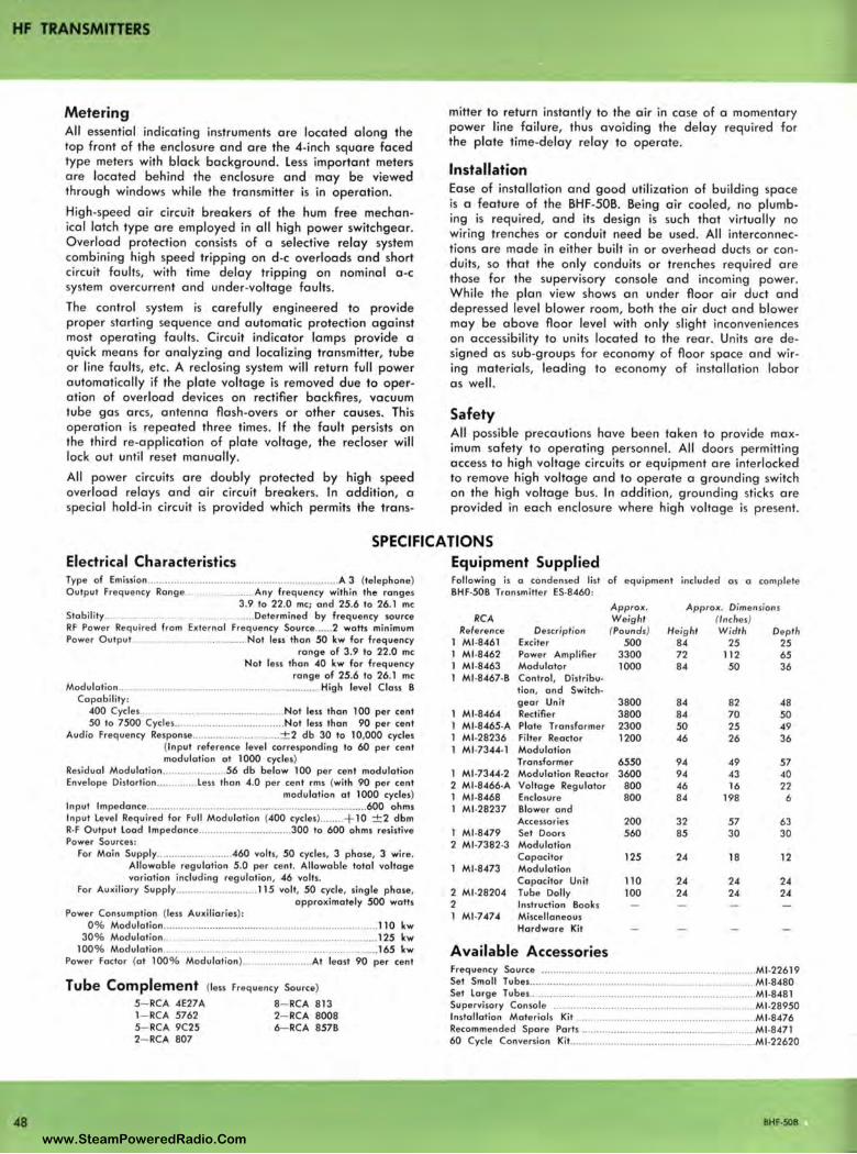
HF TRANSMITTERS
Metering All essential indicating instruments are located along the top front of the enclosure and are the 4-inch square faced type meters with black background. Less important meters are located behind the enclosure and may be viewed through windows while the transmitter is in operation.
High-speed air circuit breakers of the hum free mechanical latch type are employed in all high power switchgear. Overload protection consists of a selective relay system combining high speed tripping on d-c overloads and short circuit faults, with time delay tripping on nominal a -c system overcurrent and under-voltage faults .
The control system is carefully engineered to provide proper starting sequence and automatic protection against most operating faults . Circuit indicator lamps provide a quick means for analyzing and localizing transmitter, tube or line faults , etc. A reclosing system will return full power automatically if the plate voltage is removed due to operation of overload devices on rectifier backfires, vacuum tube gas arcs, antenna flash -overs or other causes. This operation is repeated three times. If the fault persists on the third re-application of plate voltage, the recloser will lock out until reset manually.
All power circuits are doubly protected by high speed overload relays and air circuit breakers. In addition, a special hold-i n circuit is provided which permits the trans-
mitter to return instantly to the air in case of a momentary power line failure, thus avoiding the delay required for the plate time-delay relay to operate.
Installation Ease of installation and good utilization of building space is a feature of the BHF-50B. Being air cooled, no plumbing is required, and its design is such that virtually no wiring trenches or conduit need be used . All interconnections are made in either built in or overhead ducts or conduits, so that the only conduits or trenches required are those for the supervisory console and incoming power. While the plan view shows an under floor air duct and depressed level blower room, both the air duct and blower may be above floor level with only slight inconveniences on accessibility to units located to the rear. Units are designed as sub-groups for economy of floor space and wiring materials, leading to economy of installation labor as well.
Safety All possible precautions have been taken to provide maximum safety to operating personnel. All doors permitting access to high voltage circuits or equipment are interlocked to remove high voltage and to operate a grounding switch on the high voltage bus. In addition, grounding sticks are provided in each enclosure where high voltage is present.
SPECIFICATIONS
48
Electrical Characteristics Type of Emission .............................. .................................... A 3 (telephone) Output Frequency Range .................. ..... . Any frequency within the ranges
3.9 to 22 .0 me; and 25.6 lo 26.1 me Stability .................................................. Determined by frequency source RF Power Required from External Frequency Source ...... 2 watts minimum Power Outpu t.. .................................... Not less than 50 kw for frequency
range of 3.9 to 22.0 me Not less than 40 kw for frequency
range of 25.6 to 26.1 me Modulotion ...................................................................... High level Class B
Capabi lity : 400 Cycles .................................................. Not less than 100 per cent 50 to 7500 Cycles .................... .................. Not less than 90 per cent
Audio Freq uency Response .............................. ± 2 db 30 to 10,000 cycles (Input reference level corresponding to 60 per cent modulation at 1000 cycles)
Residual Modulation ...................... 56 db below 100 per cent modulation Envelope Distortion .............. Less than 4.0 per cent rms (with 90 per cent
modulation at 1000 cycles) Input lmpedance ............ .................. .............................................. 600 ohms Input Level Required for Full Modulation (400 cycles) ..... ... + 10 ± 2 dbm R·F Output Load lmpedance ............ ....... .......... .. . 300 to 600 ohms resistive Power Sources:
For Main Supply ........ ................. .-460 volts, 50 cycles, 3 phase, 3 wire. Allowable regulation 5.0 per cent, Allowable total voltage variation including regulation, 46 volts.
For Au xi liary Supply .. .......................... 115 volt, 50 cycle, single phase, approximately 500 watts
Power Consumption (less Auxiliaries): 0 % Modulation ............................... ........................................ .. . 110 kw
30% Modulation .......................................................................... 125 kw 100% Modulation ...................................................................... .... 165 kw
Power Factor (at 100% Modulation) ........................ At least 90 per cent
Tube Complement (less Freq uency Source)
5- RCA 4E27A 8- RCA 813 1- RCA 5762 2- RCA 8008 5- RCA 9C25 6- RCA 857B 2- RCA 807
Equipment Supplied Following is a condensed list of eq uipment included as a complete BHF•50B Transmitter ES•8460 :
Approx. Approx. Dimensions RCA W eig ht (Inc hes)
Reference Description (Pounds) Height Width Depth Ml•8461 Exciter 500 B4 25 25 Ml•8462 Power Amplifier 3300 72 112 65 Ml•8463 Modulator 1000 84 50 36 Ml•8467•B Control, Distribu•
tion, and Switch• gea r Unit 3800 84 82 48
Ml•8464 Rectifier 3800 84 70 50 Ml•8465•A Plate Transformer 2300 50 25 49 Ml•28236 Filter Reactor 1200 46 26 36 Ml•7344·1 Modulation
Transformer 6550 94 49 57 1 Ml•7344•2 Modulation Reactor 3600 94 43 40 2 Ml•8466·A Voltage Regulator 800 46 16 22 1 M1 ·8468 Enclosure 800 84 198 6 1 Ml•28237 Blower and
Accessories 200 32 57 63 1 Ml •8479 Set Doors 560 85 30 30 2 Ml•7382·3 Modulation
Capacitor 125 24 18 12 1 Ml•8473 Modulation
Capacitor Unit 110 24 24 24 2 Ml .28204 Tube Dolly 100 24 24 2-4 2 Instruction Books 1 Ml•7-47-4 Miscellaneous
Hardware Kit
Available Accessories Frequency Source .. .... .. .. ...... .. ...................................................... Ml.22619 Set Small Tubes .............................................................................. Ml •8-480 Set Large Tubes ........................................... .. ................................. Ml •8481 Supervisory Console ........................ .... .. ... .. .. ................................. Ml •28950 Installation Materials Kit ............................ ................................. Ml •8-476 Recommended Spore Paris ............................. .... .......................... Ml •8-471 60 Cycle Conversion Kit ................................................................ Ml •22620
BHF·SOB
www.SteamPoweredRadio.Com
wigfi
Stolen 2 Line Transparent
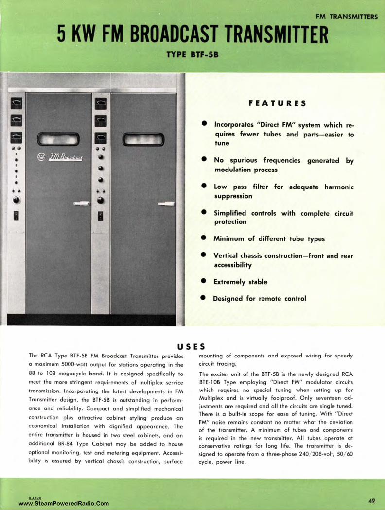
FM TRANSMITTERS
5 KW FM BROADCAST TRANSMITTER TYPE BTF-58
FEATURES
• Incorporates "Direct FM" system which requires fewer tubes and parts- easier to tune
• No spurious frequencies generated by modulation process
• Low pass filter for adequate harmonic suppression
• Simplified controls with complete ci rcuit protection
• Minimum of different tube types
• Vertical chassis construction- front and rear accessibility
• Extremely stable
• Designed for remote control
USES The RCA Type BTF-5B FM Broadcast Transmitter provides
a maximum 5000-watt output for stations operating in the
88 to l 08 megacycle band. It is designed specifically to
meet the more stringent requirements of multiplex service
transmission . Incorporating the latest developments in FM Transmitter design, the BTF-5B is outstanding in perform
ance and reliability. Compact and simplified mechanical
construction plus attractive cabinet styling produce an
economical installation with dignified appearance. The
entire transmitter is housed in two steel cabinets, and an
additional BR-84 Type Cabinet may be added to house
optional monitoring, test and metering equipment. Accessi
bility is assured by vertical chassis construction, surface
B.6545
mounting of components and exposed wiring for speedy circuit tracing .
The exciter unit of the BTF-5B is the newly designed RCA BTE- 1 OB Type employing "Direct FM" modulator circuits which requires no special tuning when setting up for Mu ltiplex and is virtually foo lproof. Only seventeen adjustments are required and all the circuits are single tuned . There is a built-in scope for ease of tuning. With " Direct FM" noise remains constant no matter what the deviation of the transmitter. A minimum of tubes and components is required in the new transmitter. All tubes operate at conservative ratings for long life. The transmitter is designed to operate from a three-phase 240/ 208-volt, 50/ 60 cycle, power line.
49 www.SteamPoweredRadio.Com
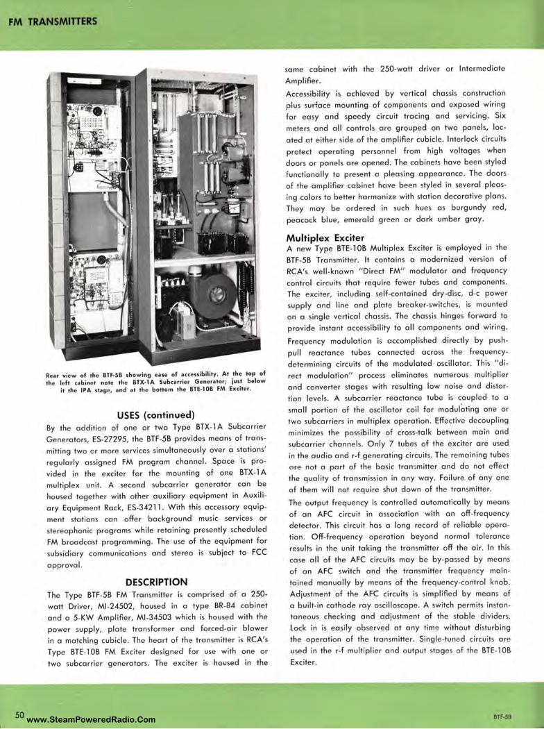
FM TRANSMITTERS
50
Rear view of the BTF-5B showing ease of accessibility. At the top of the left cabinet note the BTX-lA Subcarrier Generator; just below
it the IPA stage, and at the bottom the BTE-1 OB FM Exciter.
USES (continued) By the addition of one or two Type BTX-1 A Subcarrier
Generators, ES-27295, the BTF-5B provides means of trans
mitting two or more services simultaneously over a stations'
regularly assigned FM program channel. Space is pro
vided in the exciter for the mounting of one BTX-1 A
multiplex unit. A second subcarrier generator can be
housed together with other auxiliary equipment in Auxili
ary Equipment Rack, ES-34211 . With this accessory equip
ment stations can offer background music services or
stereophonic programs while retaining presently scheduled
FM broadcast programming. The use of the equipment for
subsidiary communications and stereo is subject to FCC
approval.
DESCRIPTION The Type BTF-5B FM Transmitter is comprised of a 250-
watt Driver, Ml-24502 , housed in a type BR-84 cabinet
and a 5-KW Amplifier, Ml -34503 which is housed with the
power supply, plate transformer and forced -air blower
in a matching cubicle . The heart of the transmitter is RCA's
Type BTE-1 OB FM Exciter designed for use with one or
two subcarrier generators . The exciter is housed in the
same cabinet with the 250-watt driver or Intermediate
Amplifier.
Accessibility is achieved by vertical chassis construction
plus surface mounting of components and exposed wiring
for easy and speedy circuit tracing and servicing. Six
meters and all controls are grouped on two panels, loc
ated at either side of the amplifier cubicle. Interlock circuits
protect operating personnel from high voltages when
doors or panels are opened. The cabinets have been styled
functionally to present a pleasing appearance. The doors
of the amplifier cabinet have been styled in several pleas
ing colors to better harmonize with station decorative plans.
They may be ordered in such hues as burgundy red,
peacock blue, emerald green or dark umber gray.
Multiplex Exciter A new Type BTE-1 OB Multiplex Exciter is employed in the
BTF-5B Transmitter. It contains a modernized version of
RCA's well-known " Direct FM" modulator and frequency
control circuits that require fewer tubes and components.
The exciter, including self-contained dry-disc, d -c power
supply and line and plate breaker-switches, is mounted
on a single vertical chassis. The chassis hinges forward to
provide instant accessibility to all components and wiring .
Frequency modulation is accomplished directly by push
pull reactance tubes connected across the frequency
determining circuits of the modulated oscillator. This " di
rect modulation" process eliminates numerous multiplier
and converter stages with resulting low noise and distor
tion levels. A subcarrier reactance tube is coupled to a
small portion of the oscillator coil for modul~ting one or
two subcarriers in multiplex operation. Effective decoupling
minimizes the possibility of cross-talk between main and
subcarrier channels. Only 7 tubes of the exciter are used
in the audio and r-f generating circuits. The remaining tubes
ore not a part of the basic transmitter and do not e ffect
the quality of transmission in any way. Failure of any one
of them will not require shut down of the transmitter.
The output frequency is controlled automatically by means
of an AFC circuit in association with an off-frequency
detector. This circuit has a long record of reliabl e opera
tion . Off-frequency operation beyond normal tolerance
results in the unit taking the transmitter off the air. In this
case all of the AFC circuits may be by-passed by means
of an AFC switch and the transmitter frequency main
tained manually by means of the frequency-control knob .
Adjustment of the AFC circuits is simplified by means of
a built-in cathode ray oscilloscope. A switch permits instan
taneous checking and adjustment of the stable dividers.
Lock in is easily observed at any tim e without disturbing
the operation of the transmitter. Single-tuned circuits are
used in the r-f multiplier and output stages of the BTE-1 OB
Exciter.
BTF-58 www.SteamPoweredRadio.Com
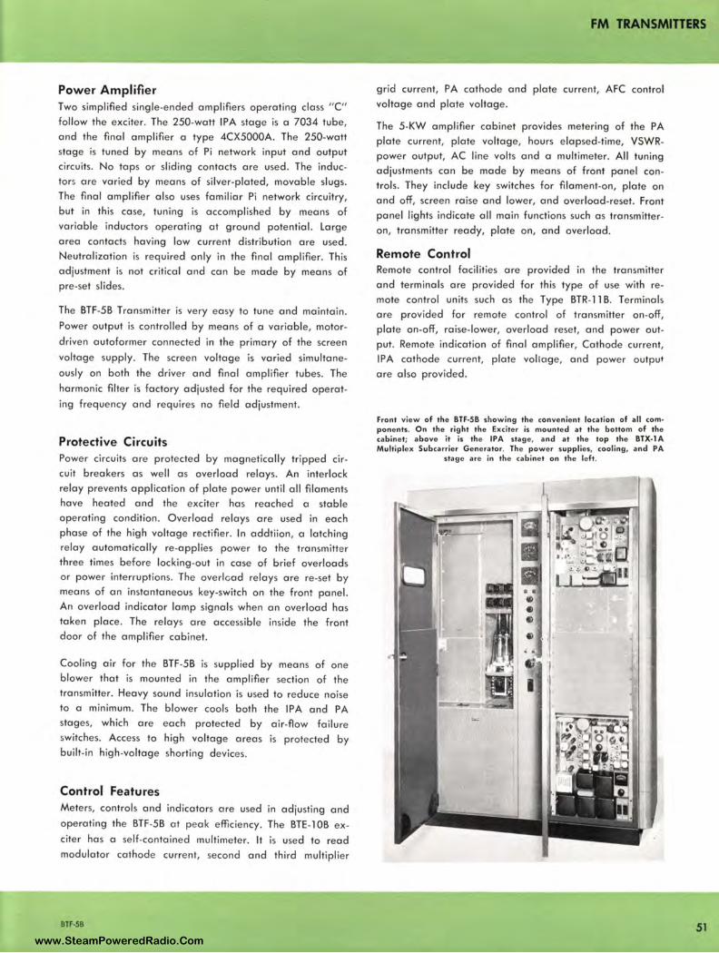
Power Amplifier Two simplified single-ended amplifie rs operating class "C" follow the exciter. The 250-watt IPA stage is a 7034 tube, and the final amplifier a type 4CX5000A. The 250-watt stage is tuned by means of Pi network input and output circuits. No taps or sliding contacts are used. The inductors are varied by means of silver-plated, movable slugs. The final amplifier also uses familiar Pi network circuitry, but in this case, tuning is accomplished by means of variable inductors operating at ground potential. Large area contacts having low current distribution are used . Neutralization is required only in the final amplifier. This adjustment is not critical and can be made by means of pre-set slides.
The BTF-58 Transmitter is very easy to tune and maintain .
Power output is controlled by means of a variable, motor
driven autoformer connected in the primary of the screen
voltage supply. The screen voltage is varied simultane
ously on both the driver and final amplifier tubes. The
harmonic filter is factory adjusted for the required operat
ing frequency and requires no field adjustment.
Protective Circuits Power circuits are protected by magnetically tripped circuit breakers as well as overload relays. An interlock relay prevents application of plate power until all filaments have heated and the exciter has reached a stable operating condition. Overload relays are used in each phase of the high voltage rectifier. In addtiion, a latching relay automatically re-applies power to the transmitter three times before locking-out in case of brief overloads or power interruptions. The overlcad relays are re-set by means of an instantaneous key-switch on the front panel. An overload indicator lamp signals when an overload has taken place. The relays are accessible inside the front door of the amplifier cabinet.
Cooling air for the BTF-58 is supplied by means of one blower that is mounted in the amplifier section of the transmitter. Heavy sound insulation is used to reduce noise to a minimum. The blower cools both the IPA and PA stages, which are each protected by air-flow failure switches. Access to high voltage areas is protected by built-in high -voltage shorting devices.
Control Features Meters, controls and indicators are used in adjusting and
operating the BTF-58 at peak efficiency. The BTE-1 OB ex
citer has a self-contained multimeter. It is used to read modulator cathode current, second and third multiplier
BTF-58
FM TRANSMITTERS
grid current, PA cathode and plate current, AFC control voltage and plate voltage.
The 5-KW amplifier cabinet provides metering of the PA plate current, plate voltage, hours elapsed-time, VSWRpower output, AC line volts and a multimeter. All tuning adjustments can be made by means of front panel controls . They include key switches for filament-on, plate on and off, screen raise and lower, and overload-reset. Front panel lights indicate all main functions such as transmitteron, transmitter ready, plate on, and overload.
Remote Control Remote control facilities are provided in the transmitter and terminals are provided for this type of use with remote control units such as the Type BTR-11 B. Terminals are provided for remote control of transmitter on-off, plate on-off, raise-lower, overload reset, and power output. Remote indication of final amplifier, Cathode current, IPA cathode current, plate voltage, and power output
are also provided.
Front view of the BTF-5B ,howing the convenient location of all com• ponents . On the right the Exciter is mounted at the bottom of the cabinet; above it is the IPA stage, and at the top the BTX-lA Multiplex Subcarrier Generator. The power supplies, cooling, and PA
stage are in the cabinet on the left.
51 www.SteamPoweredRadio.Com
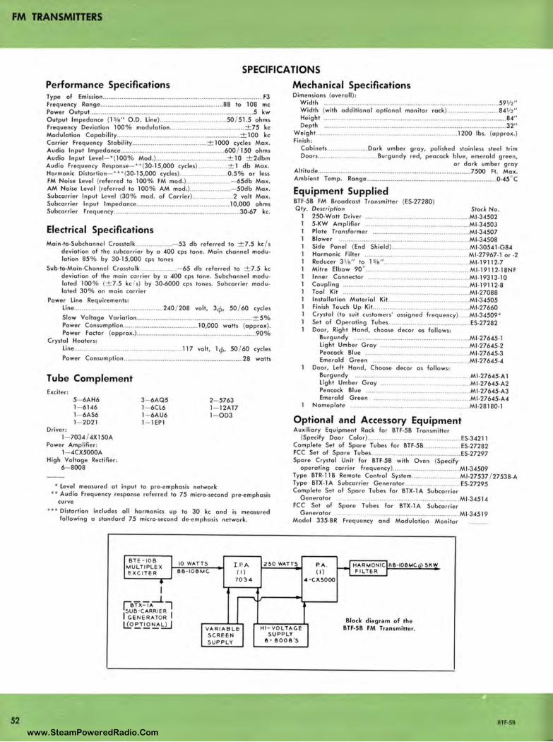
FM TRANSMITIERS
52
SPECIFICATIONS
Performance Specifications Type of Emission ......... ...... ............... ................... ............. ...... ..... .. ..... .. .... F3 Frequency Rang e ........... ... .................... ............ .... ·-··········· ···88 to l 08 me Power Output .......... ........... ............... .................. .................. .... ... ......... 5 kw Output Impedance (l %" O.D. Lin e) .............. ..... .. ... .. ....... .. . 50 / 51 .5 ohms Frequency Deviation 100% mod ulation ................................. ....... ± 75 kc Modulation Capability ................. ............ ..... ..... .......... .......... .... .. . ± 100 kc Carrie r Frequency Stability .................... ..... .. ..... ........ ± 1000 cycles Max. Audio Input lmpedance ... .. .......... .... .......... ...... ... ........... ... .... 600 / 150 ohms Audio Input Leve l- *(100% Mod.) ........................... ........... ± 10 ± 2dbm Aud io Frequency Response-**(30-15,000 cycles) ............ .... ± l db Max. Harmonic Distortion- *** (30-15,000 cycles) ......................... 0 .5% or less FM Noise Leve l (referred to 100% FM mod .) ...... ...... .......... .. - 65db Ma x. AM Noise Leve l (refe rred to 100% AM mod.) ................. ..... - 50db Ma x. Subcarrie r Input Leve l (30% mod. of Carrie r) .......... ............ 2 volt Max. Subcarrie r Input Impedance ............... ...... ....... .... ......... ......... l 0,000 ohms Subcarrier Frequ ency .... ....... ......... ........... ....... ............... ... ............ 30-67 kc .
Electrical Specifications Main-to-Subchannel Crosstal k .......... ... ....... - 53 db referred to ± 7.5 kc / s
deviation of th e subca rri er by a 400 cps ton e. Main channel modulation 85 % by 30• l 5,000 cps ton es
Sub-to-Main.Channe l Crosstalk ................... . - 65 db referred lo ± 7.5 kc deviation of the mai n ca rrier by a 400 cps lone. Subchanne l modulated 100% (± 7.5 kc / s) by 30-6000 cps ton es. Subcarrie r modulated 30% on ma in ca rrie r
Power Lin e Requ ire ments: Lin e ............. ............................... .... 240 / 208 volt, 3cp, 50 / 60 cycles Slow Voltage Va riation ..... ... ...... ...... ....... ........ .......... ................. ± 5% Power Consumption ....... ....... ......... ..... ............ l 0,000 walls (approx). Power Factor (approx .) .............................................. .................. 90%
Crystal Heaters: Line ................................................. ..... .... 117 volt, l cp, 50 / 60 cycles Power Consumption ..................................... .................. ·-·······28 watts
Tube Complement Exciter:
5- 6AH6 1- 6146 l - 6AS6 1- 2021
Driver: l - 7034 / 4Xl50A
Power Amplifie r: l - 4CX5000A
High Voltage Rectifier: 6- 8008
3- 6AQ5 l - 6CL6 l - 6AU6 1- lEPl
2- 5763 1- 12AT7 l - OD3
* Level mea sured al input to pre•emphasis ne twork ** Audio Frequency response refe rred to 75 micro•second pre•emphasis
cu rve
••• Distortion includes all harmonics up to 30 kc and is measured following a standard 75 micro·second de•emphasis network .
Mechanical Specifications Dimensions (ove rall ):
Width ...... .... .. ........... ............. ....... ........... ...... ... .. ............. .... ............ 59½" Width (with additional optional monito r rack) ........................ .. .. 84½ " Height .... .................... ...... ...................... ....... ........ .. .................. ... ........ 84" Depth .. .... ..... ..................... .... ...... .............. .... .... ... ... .................... ........ 32"
We ight. ... ... ......... . ................................................. 1200 lbs. (app rox.) Finish:
Cabinels .................. .... Dark umber g ray, polished sta inl ess stee l trim Doors .... ........................ .. .. Bu rgundy red, peacock blue, emerald g reen,
o r da rk umber gray Altitude ............................................. .......•...................... ....... 7500 Ft. Max. Ambient Temp. Range .. .................... ........... ............................ ......... 0•45 °C
Equipment Supplied BTF·5B FM Broadcast Transmitte r (ES.27280) Qty. Description Stock No.
l 250-Watt Driver ...... ...•...... ....... ... ..... ..... ...... .............. Ml •34502 l 5.KW Amplifi e r ..... .................................... ............... Ml .34503 l Plate Transforme r .................. .. ...... .......................... Ml -34507 l Blowe r ............. ....... ........ .. ......... ............................... Ml-34508 l Side Panel (End Shie ld) ................ .... ........... ..... ..... Ml •30541 -G84 l Harmonic Filte r ........... ....... ...................................... Ml -27967• l or •2 l Reduce r 3 1/e" to l ~e" .......................... .. ............ . .... Ml .19112-7 l Mitre Elbow 90° .. ....... .............. .......... .. ................... Ml •l9112-18NF l Inner Connector ................ .......................... ........... Ml •19313•10 l Coupling ............... ..... .. .......... .................................... Ml -19112-8 l Tool Kit ....................... ......... .... .... .... ..... ............. ...... Ml .27088 l Installation Mate rial Ki t.. ........................ . .... ......... Ml .34505 l Finish Touch Up Ki t... .................. ................ ............... Ml -27660 l Crystal (to suit custome rs' a ssigned frequ ency) ..... Ml .34509*
Se t of Operating Tubes ............................................ ES.27282 Door, Right Hand, choose decor a s follows:
Burgundy ... ............... ...................... ...................... Ml -27645-1 Light Umber Gray .... ......... ...... .. ....... ....... .... .. ...... Ml •27645-2 Peacock Blue ...... .......... ................ ...................... Ml .27645•3 Emerald Gree n .......................................... .......... Ml -27645•4
Door, Left Hand, Choose decor a s follows: Bu rgundy .. ....................................................... Ml -27645-A l light Umbe r G ray ..... .. . ...... ...... . ........ . ..... Ml •27645•A2 Peacock Blue ... ................. .... .. ...... ......... ............ Ml •27645•A3 Emerald Green ............................. .... ................. Ml -27645•A4
Nameplate .. ... ..... ................ ........ ................ ....... Ml .28180· 1
Optional and Accessory Equipment Auxiliary Equipment Rack for BTF·5B Transmitte r
(Specify Door Color) ................. ...... .............. ............. ES.34211 Complete Se t of Spare Tubes for BTF·SB ....... ... .. ........ ES.27282 FCC Se t of Spare Tubes ............................... ...... ........... ES.27297 Spa re Crystal Unit for BTF·5B with Oven (Specify
operating carrie r fr equency) .. ...................... .... ... ..... Ml .34509 Type BTR. J l B Remote Control System ... ....................... Ml•27537 / 27538•A Type BTX-1 A Subcarrier Gene ralor ...... ......... ... ..... .... .. . ES.27295 Complete Set of Spare Tubes fo r BTX. l A Subcarr ier
Gene rator .................................. ....... ... ......... ............. Ml •34514 FCC Se t of Spare Tubes for BTX-1 A Subcarrier
Ge ne rato r ........... ........ ......... .. ................ ................. Ml .34519 Model 335·BR Frequ ency and Modulation Monitor
BT E - 10 8 10 WAT TS I .P. A 2!>0 WATTS P. A . HARMON IC 6 8 · 108MC !>K W MULT IPLE X EXC ITER 66 - 106MC (I ) ( I) FILTER
703 4 4 - C.W. !>0 00
[i __ _j_7 BTX- IA
!SUB -CARRIER I C.ENERATOR Block d iag ram of the
Ll,_o !:,_T.!,2~!:2.J VARIABLE HI - VOLTAC.E BTF•SB FM Tra nsmitter. SCREEN SUPP LY SUP P LY e - 8008 's
BTF-5B
www.SteamPoweredRadio.Com
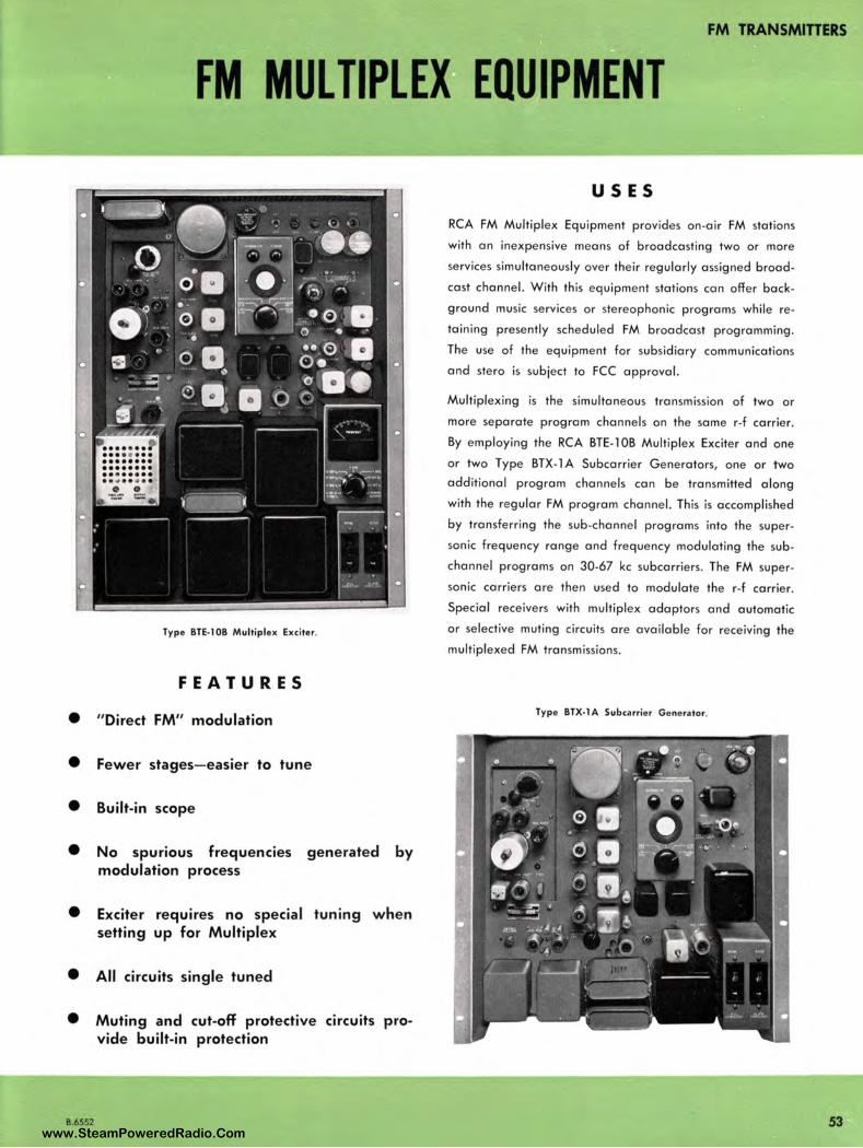
FM TRANSMITIERS
FM MULTIPLEX EQUIPMENT
Type BTE-1 OB Multiplex Exciter.
FEATURES
• " Direct FM" modulation
• Fewer stages- easier to tune
• Built-in scope
• No spurious frequencies generated by modulation process
• Exciter requires no special tuning w hen setting up for Multiplex
• All circuits single tuned
• Muting and cut-off protective circuits provide built-in protection
USES
RCA FM Multiplex Equipment provides on-air FM stations
with an inexpensive means of broadcasting two or more
services simultaneously over their regularly assigned broad
cast channel. With this equipment stations can offer back
ground music services or stereophonic programs while re
taining presently scheduled FM broadcast programming.
The use of the equipment for subsidiary communications
and stero is subject to FCC approval.
Multiplexing is the simultaneous transmission of two or
more separate program channels on the same r-f carrier.
By employing the RCA BTE-1 OB Multiplex Exciter and one
or two Type BTX-1 A Subcarrier Generators, one or two
additional program channels can be transmitted along
with the regular FM program channel. This is accomplished
by transferring the sub-channel programs into the super
sonic freq uency range and frequency modulating the sub
channel programs on 30-67 kc subcarriers. The FM super
sonic carriers are then used to modulate the r-f carrier.
Special receivers with multiplex adaptors and automatic
or selective muting circu its are available for receiving the
multiplexed FM transm issions.
Type BTX-1 A Subcarrier Generator.
8.6552 53 www.SteamPoweredRadio.Com

FM TRANSMITTERS
DESCRIPTION
The RCA Type BTE-1 OB Multiplex Exciter is a compact, self-contained unit with built-in power supplies and an oscilloscope to facilitate alignment. Miniature tubes are used throughout, and semiconductor rectifiers are used in the power supplies. The BTE-1 OB incorporates features which make it very easy to adjust and maintain, and extremely reliable in operation.
The r-f multiplier and power amplifier stages of the exciter use relatively broadband, single-tuned circuits, thus simplifying adjustment. A built-in meter can be switched to read the following voltage and currents: modulator cathode current, second and third multiplier grid currents, PA cathode and plate current, AFC control voltage, and plate voltage. A monitor oscilloscope incorporated in the exciter simplifies adjustment and maintenance of the AFC frequency dividers. A switch permits instantaneous checking and adjustment of all five dividers and a check of the control action of the phase detector. Displays are in the form of Lissajous' figures , with the advantage that lock-in of the divide rs can be easily observed. Checks can be made during operation without disturbing the AFC action in any way.
Self-contained power supplies for the BTE-1 OB employ semiconductor rectifiers throughout. The high voltage regulated supply which furnishes d-c plate and screen voltages utilizes a bridge-type germanium rectifier. Modulator and oscillator filaments are energized by a d-c supply employing a full -wave silicon rectifier.
All components of the BTE-1 OB are mounted on a vertical chassis designed for standard rack mounting. Special hinge-type mounting pins at the bottom corners permit the top of the chassis to be swung out for access to the wiring and circuit components on the underneath side.
Circuits of the BTE-1 OB, as shown in the block diagram, consist of a master oscillator which operates at 1 / 18 of the carrier frequency; two reactance modulators to provide modulation for the main channel; a third reactance modulator for the subcarrier; three frequency multipliers including the output stage to bring the output frequency up to the 88 to 108 me range; automatic frequency control circuitry; and the power supplies necessary to furnish a -c and d-c voltages for these stages. The final amplifier of the exciter acts as a doubler.
Circuit features include the use of a pushpull modulator and inductive coupling circuit that results in highly linear operation with very low harmonic distortion . Each tube becomes almost a pure reactance. Loading of the oscillator is greatly reduced thus providing better AFC action. Moreover, the pushpull modulator automatically balances out temperature and supply-voltage changes. The modulating
circuits are very effectively decoupled, min1m1zing the possibility of cross-talk between the main channel and subchannel.
The automatic frequency control circuitry of the BTE-1 OB Exciter is characterized by a long record of dependable operation. A phase detector is used to develop a control voltage which establishes and maintains a phase lock between a reference crystal oscillator and the derived signal. Thus the system is actually an automatic phase control system which achieves a stability precisely matching that of the crystal reference source . The master oscillator frequency and swing are reduced to confine phase deviations. Limited pull-in range normally associated with precise frequency control is overcome by the use of an off frequency circuit which simultaneously provides a safeguard against uncontrolled and possible off-frequency operation. The a-c overload switch can be used as a power "ON-O FF" switch, if desired, and the d-c overload switch for " Standby Plate" switching . Manual control of the oscillator is provided so that failure of any tubes or components in the AFC section will not require shutdown of the transmitter.
The BTE-1 OB Excite r is used in the RCA BTF-5B 5-KW FM transmitter. In many instances it may be used to replace the exciters in previously designe d transmitters that will not mee t the stringent requireme nts of multiplex operation .
Simplified block diagram of a BTE-1 OB Exciter, The modulator-oscillator is shown with provisions for inserting one subcarrier.
MAI N CHANNEL INPUT
INPUT F M SUBCARRIER GENERATOR
(30 ·67KC),----'-'-A ;_FC;:c_-l----l"--
CARRIER CONTROL
M UL"7 1PLl5: R - PA
SCOPE
~ \::V
POWE R SUPPLY
+JOOV DC + 6.3 V DC
6.3 V AC
RF OUTPUT 88·108 MC
B.6552
www.SteamPoweredRadio.Com
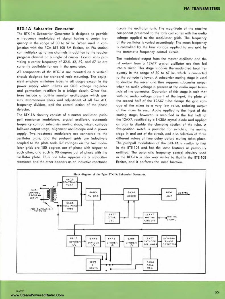
FM TRANSMITTERS
BTX-1 A Subcarrier Generator The BTX-l A Subcarrier Generator is designed to provide a frequency modulated r-f signal having a center fre
quency in the range of 30 to 67 kc. When used in conjunction with the RCA BTE-l OB FM Exciter, an FM station can multiplex up to two channels in addition to the regular
program channel on a single r-f carrier. Crystal units pro
viding a center frequency of 32.5, 42, 59, and 67 kc are currently available for use in the generator.
All components of the BTX-l A are mounted on a vertical
chassis designed for standard rack mounting. The equip
ment employs miniature tubes in all stages except in the power supply which utilizes an OD3 voltage regulator and germanium rectifiers in a bridge circuit. Other fea
tures include a built-in monitor oscilloscope which permits instantaneous check and adjustment of all five AFC
frequency dividers, and the control action of the phase
detector.
The BTX-l A circuitry consists of a master oscillator, push
pull reactance modulators, crystal oscillator, automatic
frequency control, subcarrier muting stage, mixer, cathode follower output stage, alignment oscilloscope and a power
supply. Two reaclance modulators are connected lo the oscillator plate, and the pushpull grids are inductively
coupled lo the plate tank . R-f voltages on the two modu
lator grids are 180 degrees out of phase with respect to each other, and each is 90 degrees out of phase with the
oscillator plate . Thus one tube appears as a capacitive
reactance and the other appears as an inductive reactance
across the oscillator tank. The magnitude of the reactive component presented to the tank coil varies with the audio
voltage applied to the modulator grids. The frequency of the oscillator is varied accordingly. The mean frequency
is controlled by the bias voltage applied to one grid by the automatic frequency control circuit.
The modulated output from the master oscillator and the
r-f output from a l 2AT7 crystal oscillator are then fed into a mixer. This stage supplies the modulated beat fre
quency in the range of 30 to 67 kc, which is connected to the cathode follower. A subcarrier muting stage is used
to disable the mixer and thus suppress subcarrier output when no audio voltage is present at the audio input terminals of the generator. Operation of this stage is such that
with no audio voltage present at the input, the plate of the second half of the l 2AX7 tube clamps the grid volt
age of the mixer to a very low value, reducing output
of the mixer to zero. Audio applied to the input of the muting stage, however, is amplified in the first half of
the l 2AX7, rectified by a l N38A crystal diode and applied
as bias to disable the clamping section of the tube. A five-position switch is provided for switching the muting
stage in and out of the circuit, and also selection of three different values of time delay before muting takes place.
The pushpull modulation of the BTX-l A is similar to that in the BTE- l OB and has the same features as previously
outlined. The automatic frequency control circuitry used
in the BTX- l A is also very similar to that in the BTE- l OB Exciter, and it performs the same function .
Block diagram of the Type BTX-1 A Subcarrier Generator.
B.6552
SUB· CHANNEL PROCRAM INPUT
PRE-EMPHASIS NETWORK
-----, 6AQ5
REAC.TANC. TUBE
6AQ5 REAC.TANC
TUBE
6AH6
OIVIDER
1/3
6AQ5
FM OSC .
6AH6
DIVIDER l/4
lEPl 1 ·
SCOPE
12 AT7 XTAL
osc.
6AH6
DIVIDER l/4
•
6AS6
MIXER
6AH6
DIVIDER 1/s
12 AX7 MUTI NC
CIRCUIT
12AT7 CATHODE FOLLOWER
6AU6 XTAL osc.
6C4
AMP.
MUTINC SICNAL
2/1N34A PHASE
DETECTOR
30-671'.C
55 www.SteamPoweredRadio.Com

FM TRANSMITTERS
SPECIFICATIONS
56
Type BTE-1 OB Exciter
Performance Specifications Type of Emission ........................................................................................ F3 Frequency Range ........................ .......................................... .... 88-108 mc / s' Power Output ............................................... ......... ....................... ..... 10 watts Output lmpedance ............................... ....... ................................... ... 50 ahms Frequency Deviation for 100 % modulation ................................ ± 75 kc / s Modulation Capability ...................................................... ± 100 kc / s min . Carrier Frequency Stability ......................... ........ ............. ± 1000 cps max. Aud io Input lmpedance ......................................... ................. 600 / 150 ohms Au dio Input Leve l (100 % mod.) ........................................ + 10 ± 2 dbm ' Audio Freque ncy Response (50.15,000 cps) ........ .................. ± 1 db max.' Ha rmonic Distortion (50-15,000 cps).................. 50-100: 1.5% max.'
100•7,500: 1 o/o max . 7,500-15,000: 1.5 % max.
FM No ise Leve l (referred to 100 % FM mod .) ...................... - 65 db max. AM Noise Level (referred to carrier voltage) ........................ - 50 db max . Subcarrier Inpu t Leve l (30 % mod. of carrier max .) ............ 5 vo lts max.' Subcarrier Input lm pedance .................................. .................... 10,000 ohms Subcarrie r Center Frequency Rang e ........................................ .... 30•67 kc / s Main•to•Sub•channe l Crosstalk ........................................................ - 53 db' Sub•to•Main Channe l Crosstal k ...................................................... - 65 db0
Electrical Specifications Power Lin e Requirements:
Tran smitter: Lin e ........................ 240 / 208 or 117 V, a -c, 50 / 60 cps, sing le phase Slow Voltage Variations .......................................... ...... ......... ... ± 5 % Power Consumption ........ ... ......................................... .... .. .... .. 300 watts
Crysta l Heaters: Lin e .............................................. 117 V, a ·c, 50 / 60 cps, single phase Power Consumption .................................................................. 28 watts
Tube Complement Cathode Ray Tube ............ 1 EPl
2 Reactance Modu lato r ...... 6AQ5 Master Osci lla to r ........... . 6AQ5
1 Subcarrier Modulator ...... 6CL6 2 Frequency Tripler .............. 5763
Frequ ency Double r and Power Amplifi er ................ 6146
1 Frequency Div ider (1/3) 6AH6 2 Freque ncy Divider (¼) 6AH6
Mechanical Specifications
Frequency Divider (1 / 5) 6AH6 Crystal Osci llator .......... .. 6AU6 Crysta l Frequency Divider (1 / 5) .................. 6AH6 Cathode Follower .. ........ 12AT7 Off-Frequency Detector .... 6AS6 Off-Frequency Control.. .. 2D21 Voltage Regulator ............ OD3
Overa ll Dimensions ................................. 24½" high, 19" wide, 11 " deep Weight ........................................................ ...................................... 80 lbs. Maximum Altitude .................................. ... ................................... 7500 feet Ambient Temperature Range ..................... .. ............................... ...... 0·45°C
Equipment Supplied Type 8TE• l OB FM Exciter ...................................... .. .................. ES-27278 Comprising th e following :
1 FM Exciter Unit ...... ............................................................. Ml 34501 1 Crysta l Unit .................................................................... ...... Ml -34509*
(*Sales Order mu st specify crystal frequ ency ) 1 Set of Opera ting Tubes ........................................................ Ml •34510 2 Instruction Book .................................................................. IB·30262
1 Level measured at input lo pre •:?mphasis network using 400 cps tone . 2 Aud io frequency response referred to 75 µs pre•emphasis curve. :i Distortion includes all harmonics up to 30 kc / s and is measured following a
standard 75 µ.s de•emphasis network. " Subcarrier modula tion percentage can be brought to 50%, if required . :, Reference shal! be :t:7.5 kc / s deviation of the subcarrier by a 400 cps tone.
Main.channel modulated 85% by 50•15,000 cps tones.
Type BTX-1 A Sub-Carrier Generator
Performance Specifications Type of Modulat ion ................................... ............................................... FM
Center Frequency Rang e of Sub-carrie r ...................................... 30-67 kc / s
Output Voltage .......................................................................... 5 volts min .
Source Resista nce ............................. Approx . 400 ohms, cathode follower
Frequency Deviation (100 % subcarrier mod .) ............................ ± 7.5 kc / s
Modulation Capability .................................................................. ± 25 kc / s
Carrier Frequency Stability .......................................................... ± 500 cps
Audio Input lmpedance ......... ............................................... 600 / 150 ohms
Audio Input Level (100 % mod.) ... .................................... ... + 10 ± 2 dbm '
Audio Frequency Response (50•6,000 cps)' ·····················-···± 1 db max.'
Ha rmonic Distortion (50-6,000 cps) ......... .. ............................... 1.5 % max."
FM Noise Level (referred to 100 % mod.) .............................. - 60 db max .
AM Noise Leve l (referred to ca rrier) ................................... - 50 db max.
Electrical Specifications Power Line Requirements:
Line ........................... ............. 240 / 208 V, a ·c, 50 / 60 cps, sing le phase Slow Voltage Variation ................ ...... .................... ... ..................... ± 5 % Powe r Consumption .......................................... ....... ................... l 00 watts
Tube Complement 2 Reactance Modulator .... .. 6AQ5
Master Oscillator ............ 6AQ5
Crystal O scil lato r # 1.. .. 12AT7
Mixer .................. .... ........ 6AS6
Cathode Follower .............. 6C4
1 Freque ncy Divider (1/3) 6AH6
2 Frequency Divide r (¼) 6AH6
Mechanical Specifications
Frequency Divider (1 / 5) 6AH6
Crystal O scillator # 2 .... 6AU6
Cathode Follower ...... .... 12AT7
Subcarrie r Mut ing .......... 12AX7
Voltage Regulator ............ OD3 Cathode Ray Tube .......... 1 EPl
Overall Dimension s .............................. .... 17½" high , 19" wide, 1 0" deep
Weight ......................................... ..................................................... 40 lbs.
Maximum Altitude ...................................... ......... .......................... 7500 feet
Ambient Temperature Rang e ............................................. ................. 0•45 ° C
Equipment Supplied Type BTX-1 A Subcarrier Generator ............................................ ES.27295
Comprising the following : 1 Subcarrier Ge ne rator Unit .................................................. Ml •34500 1 Set of Operating Tubes ........................................................ Ml -34514 1 Crystal Unit, Type CR-18 / U ................................................ Ml -34520*
(*Order must specify frequency of 67, 58, 42, or 32.5 kc) In struction Book ............................. ....................................... IB•30262
Accessory Equipment Spare Set of Opera ting Tubes for BTE•l0B Exciter .................. Ml -34510
Set of Spare FCC Tubes for BTE-l 0B Exciter .............................. M1 •34515
Spare Set of Operating Tubes for BTX-1 A Subcarrier Generator ..... ............. ............................................ Ml .34514
Set of Spare FCC Tubes for BTX-1 A Subcarrier Generator ...... Ml .34519
Spare Crystal for BTE-1 OB Exciter .............................................. Ml •34509* (* Sales order must specify channel freq uency.)
I\ Reference shal l be ± 75 kc deviation of the main--carr ier by a 400 cps tone . Sub•channel modulated 100% (±7 .5 kc / s) by 50-6,000 cps tones .
r For use in a stereophonic system the sub-channel frequency response is 50•15,000 cps. No changes will have to be made in the BTE-10B Exci ter.
8 Coil fu rnished for 44 to 54 me for use where a doubler fo ll ows the exci ter.
8.6552
www.SteamPoweredRadio.Com
wigfi
Stolen 2 Line Transparent
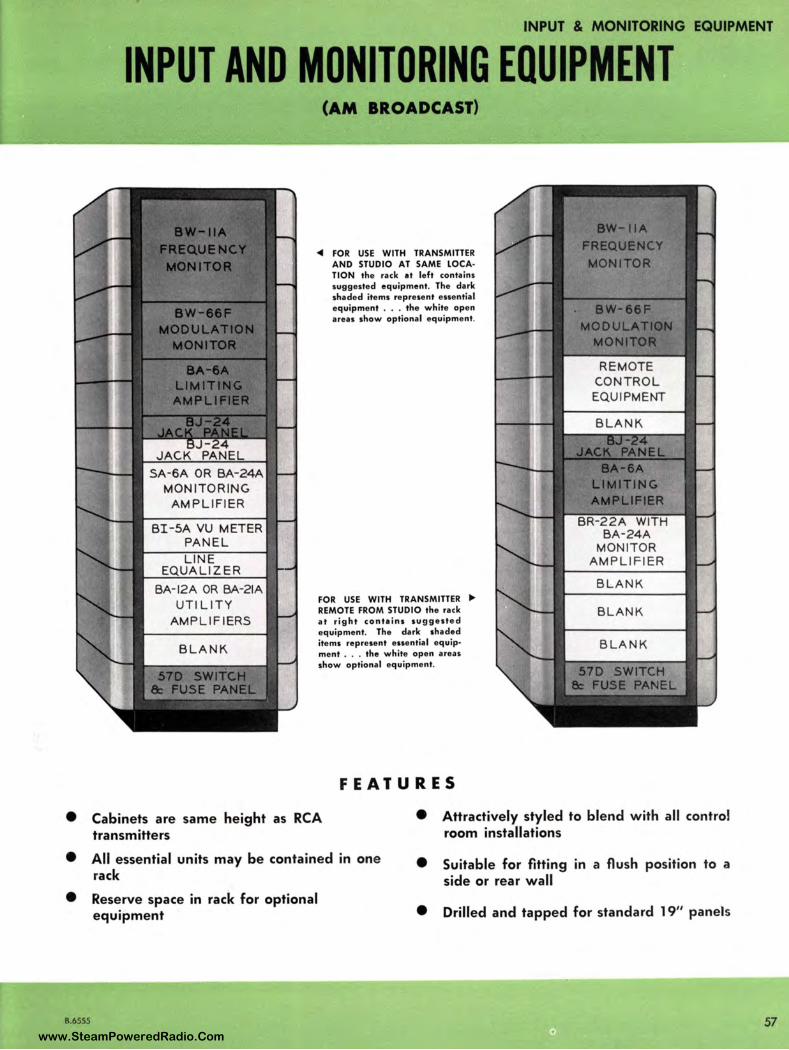
• • •
B.6555
INPUT & MONITORING EQUIPMENT
INPUT AND MONITORING EQUIPMENT
-:-at---- SA-6A OR BA-24A MONITORING
AMPLIFIER
BI-5A VU METER PANEL LINE
EQUALIZER
BA-12A OR BA-21A UTILITY
AMPLIFIERS
(AM BROADCAST)
• FOR USE WITH TRANSMITTER AND STUDIO AT SAME LOCATION the rack at left conta ins suggested equipment. The dark shaded items re present essentia l equipment •• . the white open a reas show optional equ ipme nt.
FOR USE WITH TRANSMITTER • REMOTE FROM STUDIO the rack at ri ght contai ns suggested equipment. The dark sha ded items represent essentia l equ ip• ment .. . the white open a reas show optional equipment.
FEATURES
BLANK
BLANK
BLANK
Cabinets are same height as RCA • Attractively styled to blend with all control transmitters room installations
All essential units may be contained in one • Suitable for fitting in a flush position to a rack side or rear wall Reserve space in rack for optional equipment • Drilled and tapped for standard 19" panels
57 www.SteamPoweredRadio.Com

INPUT AND MONITORING EQUIPMENT
58
USES The RCA Standard BR- l 9A or BR-84 Rack as shown con
tains all the essential equipment needed to fulfill FCC
monitoring requirements and necessary input functions.
DESCRIPTION A typical RCA Input and Monitoring Rack may contain,
depending on station's requirements:
l. The RCA AM Frequency Deviation Monitor, Type
BW-11 A, which indicates continuously and directly in
cycles-per-second any departure from the assigned
frequency . It bears FCC approval Number 1471 , for
use in Standard Broadcast stations. It has an c:ccurocy
of better than ± l O parts per million .
2 . The RCA AM Modulation Monitor Type BW-66F gives
continuous direct reading indication in percentage of
carrier modulation . It will indicate program level, car
rier shift, and provide demodulation for distortion and
frequency response measurements.
3. The RCA limiting Amplifier Type BA-6A serving as an
automatic means of increasing program level while
limiting peaks to prevent over-modulation, and adja
cent channel interference. This amplifier provides for
a more effective use of transmitter power by allowing
the system to be operated as near maximum modula
tion as possi ble, thus permitting greater coverage at
a fixed power input.
4. The RCA Standard Jack Panel Type BJ -24, provided
to improve the overall operating flexibil ity of a Broad
cast Station. With the use of patch cords, many
combinations of input and output circuits con be
realized . It can be used freely in emergencies and for
test purposes. Spacing of jack pairs prevents cross
circuit patching.
5. The RCA Switch and Fuse Panel, Type 57-D, provides
master switch and fuses for the rack mounted equ'ip
ment with a 'power-on' indicator light and removable
door for fuse access.
* If studio and transmitter ore to be at the same location,
some of the following equipments may be desired to in
crease the efficiency of your operation and can be installed
in the Input and Monitoring Equipment Rack:
6. An additional RCA Standard Jack Panel Type BJ -12 or BJ-24.
7 . An RCA Monitoring Amplifier Type SA-6A or BA-24A.
8. An RCA VU Meter Panel Type Bl -5A.
9. An RCA line Equalizer.
l 0 . An RCA Utility Amplifier Type BA- l 2A or BA-21 A.
** If Transmitter will be located remotely from your studio, some of the following equipment may be desired and can be installed in the Input and Monitoring Equipment Rack:
6. The RCA Remote Control System Receiver Type BTR-11 B/ 20A for unattended transmitter operation.
7 . An RCA type Monitor Amplifier Type SA-6A or BA-24A.
SPECIFICATIONS Complete de tailed specifications on each of these approved Input and Monitoring Equipments may be found in this catalog or in the RCA Audio Equipment Catalog.
A typical Input and Monitoring Rack adjacent to an RCA 250 Watt Transmitter (BTA-250M). Rack can be located separately in any
transmitter set-up.
B.6555 www.SteamPoweredRadio.Com
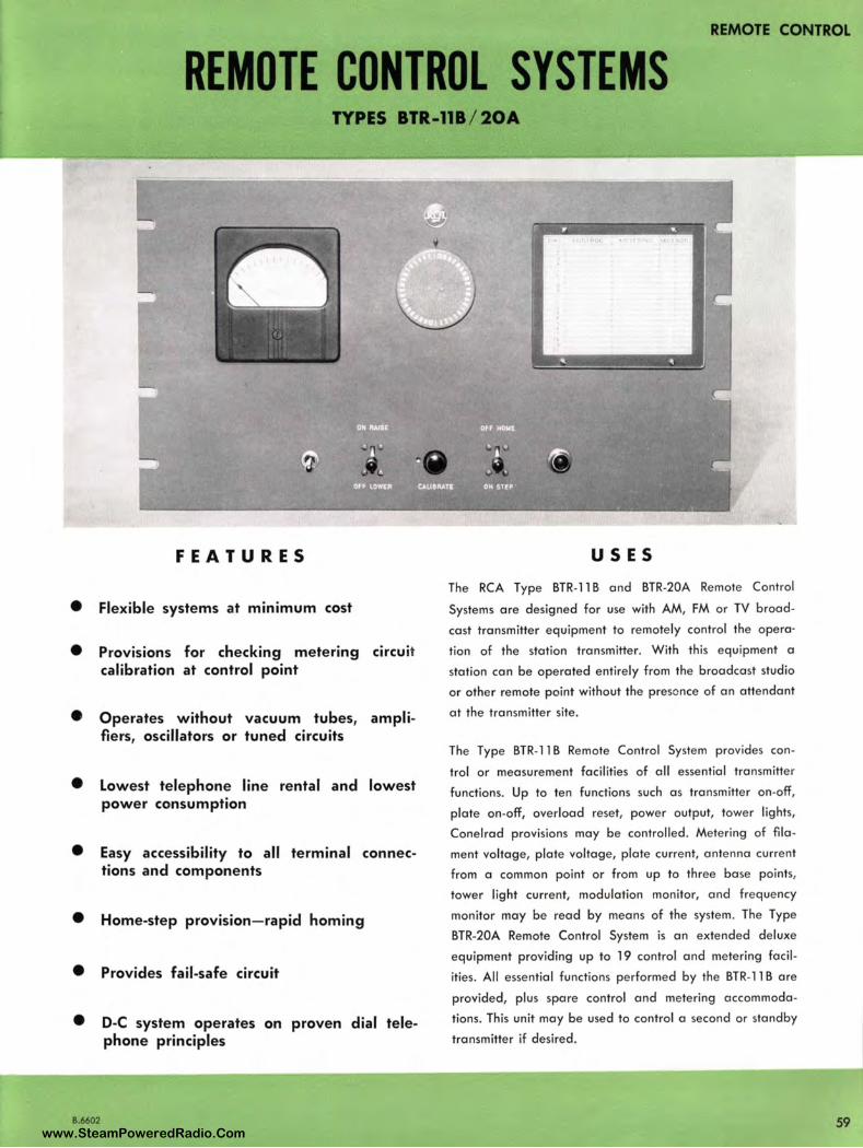
REMOTE CONTROL
REMOTE CONTROL SYSTEMS TYPES BTR-118 / 20A
FEATURES
• Flexible systems at minimum cost
• Provisions for checking metering circuit calibration at control point
• Operates without vacuum tubes, amplifiers, oscillators or tuned circuits
• Lowest telephone line rental and lowest power consumption
• Easy accessibility to all terminal connections and components
• Home-step provision- rapid homing
• Provides fail-safe circuit
• D-C system operates on proven dial telephone principles
B.6602
I
USES
The RCA Type BTR-11 B and BTR-20A Remote Control
Systems are designed for use with AM, FM or TV broad
cast transmitter equipment to remotely control the opera·
tion of the station transmitter. With this equipment a
station can be operated entirely from the broadcast studio
or other remote point without the presence of an attendant
at the tra nsmitter site.
The Type BTR-11 B Remote Control System provides con
trol or measurement facilities of all essential transmitter
functions. Up to ten functions such as transmitter on-off,
plate on-off, overload reset, power output, tower lights,
Conelrad provisions may be controlled. Metering of fila
ment voltage, plate voltage, plate current, antenna current
from a commo n point or from up to three base points,
tower lig ht current, modu lation monitor, and frequency
monitor may be read by means of the system . The Type
BTR-20A Remote Control System is an extended deluxe
equipment providing up to 19 control and metering facil
ities . All essential functions performed by the BTR-11 B are
provided, plus spare control and metering accommoda
tions. This unit may be used to control a second or standby
transmitter if desired.
59 www.SteamPoweredRadio.Com
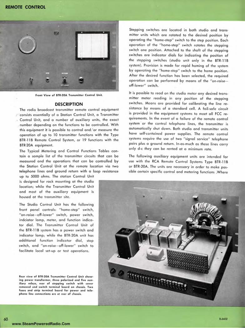
REMOTE CONTROL
60
Front View of BTR-20A Transmitter Control Unit.
DESCRIPTION The radio broadcast transmitter remote control equipment consists essentially of a Station Control Unit, a Transmitter Control Unit, and a number of auxiliary units, the exact number depending on the functions to be controlled. With this equipment it is possible to control and/ or measure the operation of up to l 0 transmitter functions with the Type BTR-11 B Remote Control System, or 19 functions with the
BTR·20A equipment.
The Typical Metering and Control Functions Tables contain a sample list of the transmitter circuits that can be measured and the operations that can be controlled by the Station Control Unit at the remote location via two telephone lines and ground return with a loop resistance up to 5000 ohms. The station Control Unit
is designed for rack mounting at the studio location; while the Transmitter Control Unit and most of the auxiliary equipment is
housed at the transmitter site .
The Studio Control Un it has the following front panel controls: " home-step" switch,
" on-raise- off-lower" switch , power switch , indciator lamp, meter, and function indica
tor dial. The Transmitter Control Unit of the BTR-11 B system has a power switch and
indicator lamp; while the BTR-20A unit has
additional function indicator dial , step switch, and "on-raise- off-lower" switch to
facilitate local set-up or test operations.
Rear view of BTR-20A Transmitter Control Un it show• ing power transformer, three polarized and five aux• iliary relays, rear of stepping switch with cover removed and switch terminal board on chassis. Two fuses and strip terminal board for power and tele• phone line connections are at rear of chassis .
Stepping switches are located in both studio and trans· mitter units which are rotated to the desired position by operating the " home-step" switch to the step position. Each operation of the " home-step" switch rotates the stepping switch one position. Attached to the shaft of the stepping switches are indicator dials for indicating the position of
the stepping switches (studio unit only in the BTR-11 B
system). Provision is made for rapid homing of the system by operating the " home-ste p" switch to the home position . After the desired function has been selected, the required operation can be performed by means of the " on-raiseoff-lower" switch.
It is possible to read on the studio mete r any desired transmitter meter reading in any position of the stepping switches. Means are provided for calibrating the line resistance by means of a standard cell. A fail-safe circuit is provided in the equipment systems to meet all FCC requirements. In the event of a failure of the remote control system or the control telephone lines, the transmitter is automatically shut down. Both studio and transmitter units have self-contained power supplies. The remote control systems require the use of two "signal service" telephone pairs plus a ground return. In-as-much as these lines carry only d-c they can be rented at a minimum rate.
The following auxiliary equipment units are intended for
use with the RCA Remote Control Systems Type BTR-11 B
or BTR-20A. The units are necessary in order to make possible certain specific control and metering functions .Where
8.6602
www.SteamPoweredRadio.Com
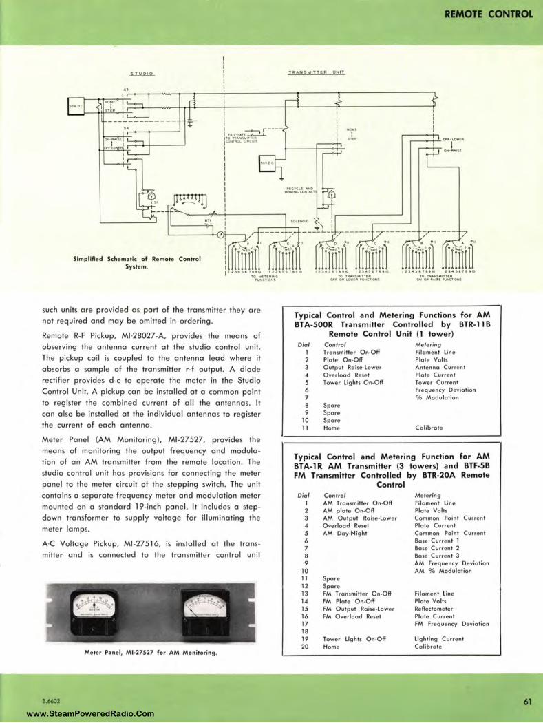
"
Simplifled Schematic of Remote Control System.
FAIL·3AFE r ---lTO TA:ANSMlnCA CONtA01.. c1 .. cu1t
TO MffEIUtH;. FUNCTIONS
such units are provided as part of the transmitter they are
not required and may be omitted in ordering .
Remote R-F Pickup, Ml-28027-A, provides the means of
observing the antenna current at the studio control unit.
The pickup coil is coupled to the antenna lead where it
absorbs a sample of the transmitter r-f output. A diode
rectifier provides d-c to operate the meter in the Studio
Control Unit. A pickup can be installed at a common point
to register the combined current of all the antennas. It
can also be installed at the individual antennas to register
the current of each antenna _
Meter Panel (AM Monitoring ), Ml-27527, provides the
means of monitoring the output frequency and modula
tion of an AM transmitter from the remote location. The
studio control unit has provisions for connecting the meter
panel to the meter circuit of the stepping switch. The unit
contains a separate frequency meter and modulation meter
mounted on a standard 19-inch panel. It includes a step
down transformer to supply voltage for illuminating the
meter lamps.
A-C Voltage Pickup, Ml -27516, is installed at the trans
mitter and is connected to the transmitter control unit
Meter Pane l, Ml-27527 for AM Monitoring .
B.6602
REMOTE CONTROL
"T R A. N S ~ ITT E R UNIT
"-fC.YCLE ANO H01,t1N(, CONT.-C.l
SOLENOID
!10Mf
I STEP
TO 111!:ANS,.,ITlE'I O,.F OA L.OWEA fUNC110NS
,----<-+-- OFF f OWEA
ON-RAISE
TO TRANS MITTUI ON 0" ltAISIE "'-'"CllOHS
Typical Control and M etering Functions for AM BTA-S00R Transm itter Controlled by BTR-11 B
Remote Control Unit (1 tower) Dial Control Metering
1 Transmitter On-Off Filament line 2 Plate On-Off Plate Volts 3 Output Raise-Lower Antenna Current
4 Overload Reset Plate Current 5 Tower lights O n-Off Tower Current 6 Frequency Deviation 7 % Modulatio n 8 Spare 9 Spore
10 Spare 11 Home Calibrate
Typical Control and M etering Function for AM BTA-1 R AM Transmitter (3 towers) and BTF-5B FM Transmitter Controlled by BTR-20A Remote
Dial 1 2 3 4 5 6 7 8 9
10 11 12 13 14 15 16 17 18 19 20
Control Control AM Transmitter On-Off AM plate On-Off AM Output Raise-Lower Overload Reset AM Day-Night
Spare Spare FM Transmitter On-Off FM Plate On-Off FM Output Ra ise-Lower FM Overload Reset
Tower lights On-Off Home
Metering Filament Line Plate Volts Common Point Current Plate Current Common Point Current Base Current 1 Base Current 2 Base Current 3 AM Frequency Deviation AM % Modulation
Filament line Plate Volts Reflectometer Plate Current FM Frequency Deviation
lighting Current Calibrate
61 www.SteamPoweredRadio.Com
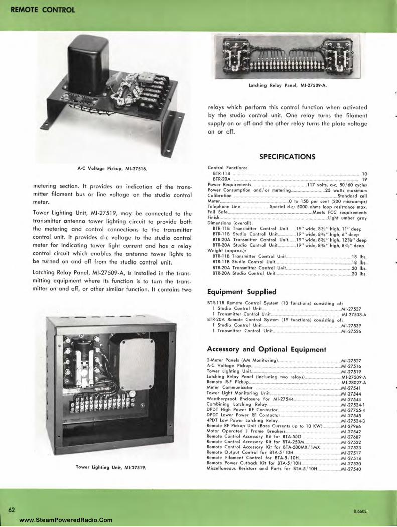
REMOTE CONTROL
62
A·C Voltage Pickup, Ml•27516.
metering section. It provides an indication of the transmitter filament bus or line voltage on the studio control meter.
Tower Lighting Unit, Ml-27519, may be connected to the transmitter antenna tower lighting circuit to provide both the metering and control connections to the transmitter control unit. It provides d-c voltage to the studio control meter for indicating tower light current and has a relay control circuit which enables the antenna tower lights to be turned on and off from the studio control unit.
Latching Relay Panel, Ml-27509-A, is installed in the transmitting equipment where its function is to turn the transmitter on and off, or other similar function . It contains two
----- -
Tower Lighting Unit, Ml-27519.
Latching Relay Pane l, Ml•27509·A.
relays which perform this control function when activated by the studio control unit. One relay turns the filament supply on or off and the other relay turns the plate voltage on or off.
SPECIFICATIONS Control Functions:
BTR. 118 ........ . ........... 10 BTR-20A .................................................... ..................... .. ............. .... 19
Power Requirements .......................................... 117 volts, O · C, 50 / 60 cycles Power Consumption and / or metering .......................... 25 watts maximum Calibration .... .... .............. ................................. ....................... Standard cell Meter ... ................................................. 0 to 150 per cent (200 microomps) Telephone Line ..................... Special d·c; 5000 ohms loop resistance max. Foil Sofe ........ .................................... .................... Meets FCC requirements Finish ................................. ................................................. Light umber gray Dimensions (overall) :
BTR• 118 Transmitter Control Unit ...... 19" wide, 8¾" high , 11 " deep BTR. 118 Studio Control Unit .............. 19" wide, 8 ¾ " high, 6" deep BTR·20A Transmitter Control Unit. ..... 19" wide, 8¾" high , 127/e" deep BTR•20A Studio Control Unit.. ............ 19" wide, 8¾" high, 81/e" deep
Weight (approx.): BTR•l 18 Transmitter Control Unit.. ......................................... 18 lbs. BTR• 118 Studio Control Unit........ . ............................................ 18 lbs. BTR•20A Transmitter Control Unit .. ...... ...... ..... ..... ........... .......... ..... 20 lbs. BTR•20A Studio Control Unit ....... ....... ... ............ .... .... ................ ..... 20 lbs.
Equipment Supplied BTR• 118 Remote Control System (10 functions ) consisting of:
l Studio Control Unit................. .. . ............................... Ml •27537 l Transmi tter Control Unit .......................................... Ml•27538·A
BTR·20A Remote Control System (19 functions) consisting of : l Studio Control Unit. .......................................................... Ml •27539 l Transmitter Control Un it. ................... ............. •...... Ml .27526
Accessory and Optional Equipment 2•Meter Panels (AM Monitoring ) ............................................... Ml•27527 A-C Voltage Pickup .... .............................................. .................. Ml •27516 Tower Lighting Unit ................................ ............ ........................ Ml•27519 Latching Relay Pan el (including two relays) ........................... Ml •27509•A Remote R· F Pickup ........................... ......... .......... ............ ............ Ml•28027•A Meter Communicator ... .................. ............................. .............. Ml•27541 Tower Light Monitoring Unit.......... .... .. .......•.. • ............. M1 •27544 Weatherproof Enclosure for Ml•27544..... ......•• . Ml.27543 Combining Latching Relay ........ .... ............. . ................ Ml .27524• l DPDT High Power RF Contoctor ... .. . ...... ...... ............ Ml •27755·4 DPDT Lower Power RF Contoctor .. . ................................. Ml .27545 4PDT Low Power Lotching Relay... . . .. Ml .27524•3 Remote RF Pickup Unit (Bose Curre nts up to 10 KW)... . . ..Ml •27966 Motor Operated J Frame Breakers.......... ........... ...... .. ..Ml .27542 Remote Control Accessory Kit for BTA•5DG...... .. .......... . .. Ml .27687 Remote Control Accessory Kit for BTA·250M.... ... . ......... . ... Ml .27522 Remote Control Accessory Kit for BTA·500MX / 1MX ............ Ml •27523 Remote Output Control for BTA·5 / 10H .................................. Ml .27517 Remote Filament Control for BTA-5 / l OH .. . ..... .. . ........... Ml -27518 Remote Power Cutback Kit for BTA·5 / l0H ............................ Ml.27520 Miscellaneous Resistors and Ports for BTA·5 / 10H .................. Ml •27540
8.6602
www.SteamPoweredRadio.Com
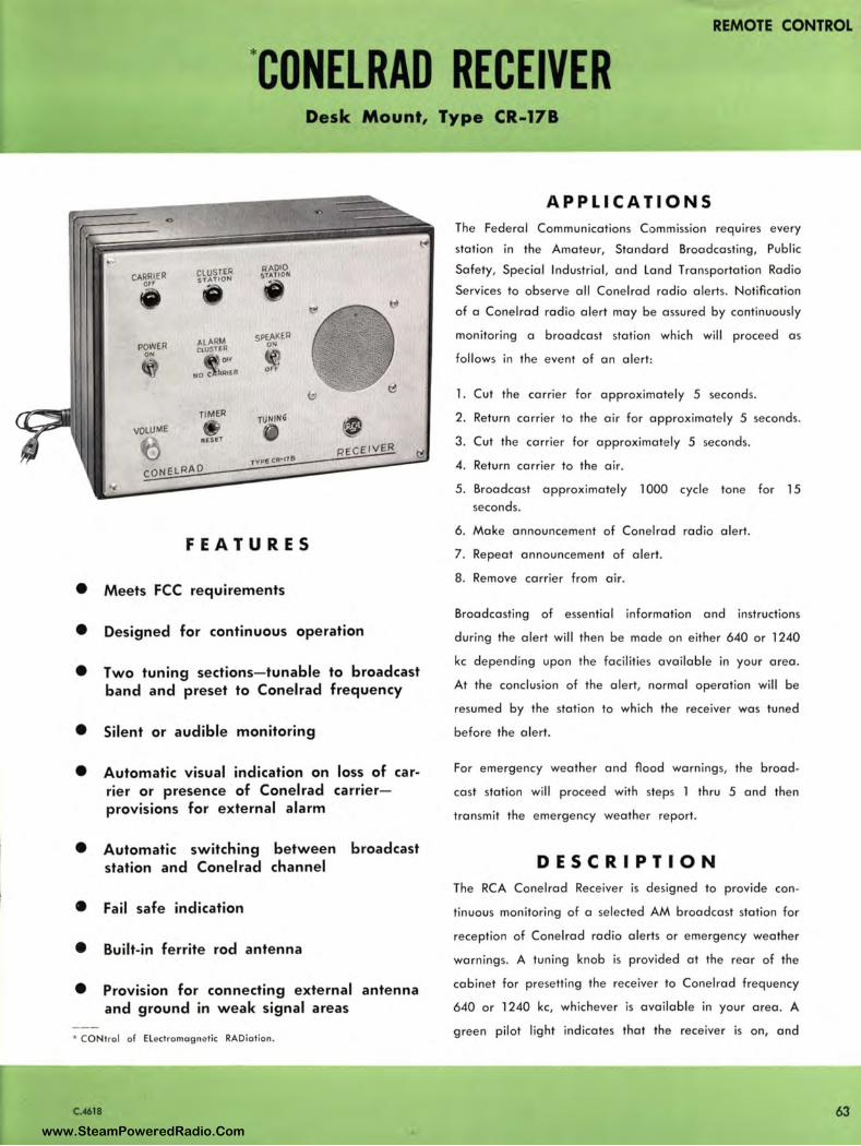
REMOTE CONTROL I
*CONELRAD RECEIVER Desk Mount, Type CR-17B
CLUSTER RADIO CARRIER STATION $TIITION
orr
ALARM SPEA!<EA POWER CLVSTER
ON
or< Off
NOC R1tP 0
TIMER TlJNf llG • VOLUME • ttESltT
£_Q NHR J.l. O TypgCA•J71l
FEATURES
• Meets FCC requirements
• Designed for continuous operation
• Two tuning sections-tunable to broadcast band and preset to Conelrad frequency
• Silent or audible monitoring
• Automatic visual indication on loss of carrier or presence of Conelrad carrierprovisions for external alarm
• Automatic switching between broadcast station and Conelrad channel
• Fail safe indication
• Built-in ferrite rod antenna
• Provision for connecting external antenna and ground in weak signal areas
• CONtrol of Elect romagne tic RADiation .
C.-4618
APPLICATIONS The Federal Communications Commission requires every
station in the Amateur, Standard Broadcasting, Public
Safety, Special Industrial, and Land Transportation Radio
Services to observe all Conelrad radio alerts. Notification
of a Conelrad radio alert may be assured by continuously
monitoring a broadcast station which will proceed as
follows in the event of an alert:
1. Cut the carrier for approximately 5 seconds.
2. Return carrier to the air for approximately 5 seconds.
3. Cut the carrier for approximately 5 seconds.
4. Return carrier to the air.
5. Broadcast approximately 1000 cycle tone for 15 seconds.
6. Make announcement of Conelrad radio alert.
7 . Repeat announcement of alert.
8. Remove carrier from air.
Broadcasting of essential information and instructions
during the alert will then be made on either 640 or 1240
kc depending upon the facilities available in your area .
At the conclusion of the alert, normal operation will be
resumed by the station to which the receiver was tuned
before the alert.
For emergency weather and flood warnings, the broad
cast station will proceed with steps 1 thru 5 and then
transmit the emergency weather report.
DESCRIPTION The RCA Conelrad Receiver is designed to provide con
tinuous monitoring of a selected AM broadcast station for
reception of Conelrad radio alerts or emergency weather
warnings. A tuning knob is provided at the rear of the
cabinet for presetting the receiver to Conelrad frequency
640 or 1240 kc, whichever is available in your area. A
green pilot light indicates that the receiver is on, and
63 www.SteamPoweredRadio.Com
REMOTE CONTROL
64
D E S C R I P T I O N (Continued)
that the carrier of the selected broadcast station is being
received . A toggle switch provides either audible moni
toring, or silent monitoring to eliminate nuisance noise in
your radio room. Absence of a carrier or receiver failure
is indicated by a red pilot light.
In the absence of a carrier, the RCA Conelrod Receiver
automatically switches between the broadcast channel and
the Conelrod channel until a carrier is received. During
this process the red light (indicating the absence of a
carrier) will remain on. When a signal is received, the
receiver locks on that channel, the red light is extin
guished, and on orange or green pilot light will indicate
which carrier is being received (broadcast channel or
Conelrod channel).
Conelrad Radio Alert
In the event of on alert, the receiver automatically (1)
lights red indicator on front panel, (2) turns on the speaker
to receive the Conelrod alert message, and (3) switches
automatically to the pre-set conelrod frequency and
lights orange indicator. A three-position switch on the
front panel permits the pre-setting of on external alarm
circuit (to which a buzzer, bell, light or other means of
indication may be connected) so that (1) the absence of
a carrier will actuate the alarm, or (2) the presence of
the pre-set Conelrod Cluster Carrier of 640 or 1240 kc
will actuate the alarm, or (3) the alarm will remain off.
At the conclusion of the alert, the receiver automatically
returns to the regular broadcast station to which the re
ceiver was tuned before the alert.
Emergency Weather Warning
In the event of a weather warning, the receiver auto
matically turns on the speaker to receive the emergency
weather report. A switch on the front panel permits the
pre-setting of on external alarm circuit (to which buzzer,
bell, light or other means of indication may be connected)
so that the absence of a carrier or the alerting procedure
followed by the broadcast station prior to the transmission
of the emergency weather warning will actuate the alarm.
At the conclusion of the weather report, the broadcast
station will return to its normal programming and the re
ceiver may be re-set for silent monitoring.
SPECIFICATIONS
Frequency Rang e ..... .
Supply Voltage ........ .
Power Consumption .. .
Temperature Rating ..
Dimensions .
We ight :
.......................... .. . 550• l 600 kc
. ... ......................... 115 volts, 50 / 60 cycles
................................. .......................... 35 watts
. ...... - 22 ° to + 122° F. (-30 ° to + 50° C.)
.......... He ight 9 ½", Width 13½ " , Depth 6"
Net ......................................... ....... .............. ... ................ .. ............ .. 15 lbs. Shipping ... .. .......... ............................ . ..................... 24 lbs.
Finish .. . . . .... L: mbe r gray Hammeroid enamel over zinc chromate p rim er with brushed aluminum front panel
Type of Circuit. .... ........... .. . ....................................... Superheterodyne
Sensitivity ... ... . • . ........ ......... 25 microvolts at 640 kc 15 microvolts al 1240 kc
Selectivity .................................................... 40 db down al ± 16 kc
Spurious Response........... .. . ..... Image more than - 44 db al 1600 kc
Audio Output ...................•................................. .... ................. ... 1.0 wall
Duty Cycle .................................................................................... Conlinuous
Tube Complement: (1) 12BE6, (1) 12BA6, (1) 12AV6, (1) 35C5, (1) 12AT7, (1) 35W4
Ordering Information Equipment includes receiver, a•C power supply, loudspeaker, built-in ferrite rod antenna, and one set of tubes housed in on attractive desk cabinet containing a control panel and 6•foot a-c cord with plug . Re• ceiver shipped complete and ready for operation. Simply plug into any 115 volt, 50 / 60 cycle power outlet.
Type CR.17B Conelrad Receiver ............................................... Ml •31874•A
C.-4618
www.SteamPoweredRadio.Com
wigfi
Stolen 2 Line Transparent

REMOTE CONTROl
450 MC REMOTE PICKUP EQUIPMENT
Type CSU-1 SCH Stati on Tran,mitter-Receiver.
FEATURES
• Choice of one-way or two-way remote pickup equipment for broadcast applications
• Permits continuous operation at low main-tenance costs
• Improved frequency response
• Remote control functions available
• Available with AC or DC Power Supplies
• Line of sight range up to 30 miles
USES RCA's Remote Pickup Equipment provides an economical means of transmitting program material from a distant location to the broadcast studio. Serving as a radio link, the system permits reporting special events, sports contests, on-the-spot accidents and other newsworthy happenings; relays entertainment from remote locations, and can transmit other events of local interest.
The remote transmission equipment allows utmost programming flexibility since it requires no special installa tion or time consuming and costly telephone line charges.
B.6620
Wherever the Mobile Transmitter is located, it can be broadcasting in a matter of seconds standing still or moving. It ma y, therefore, be considered as a temporary remote studio when housed in a sports arena, auditorium, or other semi-permanent site , a mobile studio when set up in a uto or truck, or merely as a one-shot remote broadcast transmitter for reporting special events.
Remote Pickup Equipment can be used for such other services as dual freq uency operation, cuing, and to provide order service to exsiting microwave or remote pickup systems. Equipment is available for use in any of the remote pick up channels now authorized by the FCC. The 405-470 me band has become the most popular for this application since there is less interference from man-made noise, the equipment, especially the antenna, is smaller physically, so higher gain antennas can be conveniently used.
DESCRIPTION RCA VHF and UHF Equipment for Remote Pickup Applications in the 450-470 me band consist primarily of a Type CSU-15CH, 15-watt, 115 volt a -c operated station transmitter receiver combination housed in a desk type cabinet; and the Type CMU-15B 15-watt Mobile Unit for 6 or 12 volt d-c operation mo unted in a drawer type case. O ther items include suitable power supplies, antennas, transmission lines, ond test equipment. A number of
65 www.SteamPoweredRadio.Com
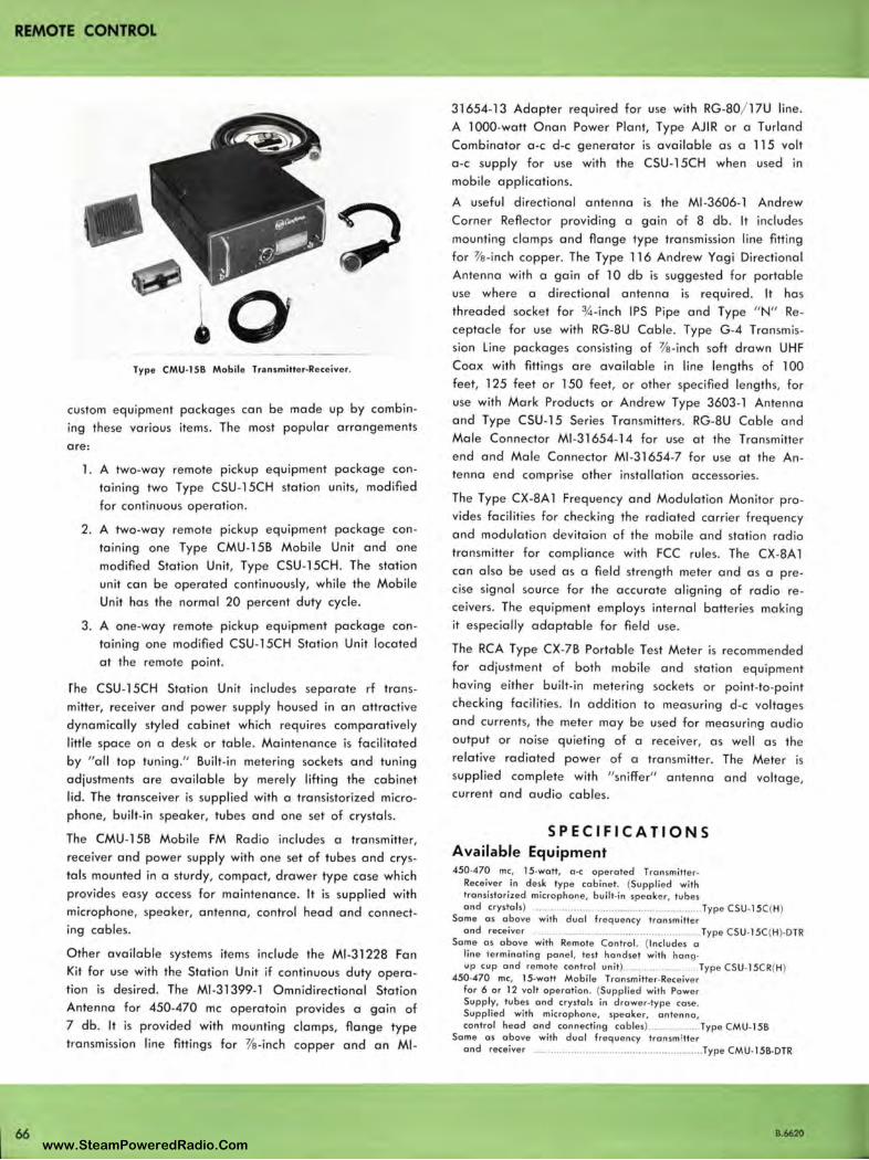
REMOTE CONTROL
66
Type CMU-1 SB Mobile Transmitter-Receiver.
custom equipment packages can be made up by combining these various items. The most popular arrangements
are:
1. A two-way remote pickup equipment package containing two Type CSU -15CH station units, modified for continuous operation.
2. A two-way remote pickup equipment package containing one Type CMU-158 Mobile Unit and one modified Station Unit, Type CSU-15CH . The station unit can be operated continuously, while the Mobile Unit has the normal 20 percent duty cycle.
3. A one-way remote pickup equipment package containing one modified CSU-15CH Station Unit located at the remote point.
rhe CSU-l 5CH Station Unit includes separate rf transmitter, receiver and power supply housed in an attractive dynamically styled cabinet which requires comparatively little space on a desk or table. Maintenance is facilitated by "all top tuning. " Built-in metering sockets and tuning adjustments are available by merely lifting the cabinet lid. The transceiver is supplied with a transistorized microphone, built-i n speaker, tubes and one set of crystals.
The CMU-158 Mobile FM Radio includes a transmitter, receiver and power supply with one set of tubes and crystals mounted in a sturdy, compact, drawer type case which provides easy access for maintenance. It is supplied with microphone, speaker, antenna, control head and connecting cables .
Other available systems items include the Ml-31228 Fan Kit for use with the Station Unit if continuous duty operation is desired. The Ml -31399-1 Omnidirectional Station Antenna for 450-470 me operatoin provides a gain of 7 db. It is provided with mounting clamps, flange type transmission line fittings for 3/e-inch copper and an Ml-
31654-13 Adapter required for use with RG-80/ 1 ?U line. A 1000-watt Onan Power Plant, Type AJIR or a Turland Combinator a-c d-c generator is available as a 115 volt a -c supply for use with the CSU-15CH when used in mobile applications.
A useful directional antenna is the Ml -3606-1 Andrew Corner Reflector providing a gain of 8 db . It includes mounting clamps and flange type transmission line fitting for 3/e-inch copper. The Type 116 Andrew Yagi Directional Antenna with a gain of 10 db is suggested for portable use where a directional antenna is require d. It has threaded socket for ¾ -inch IPS Pipe and Type " N" Receptacle for use with RG-8U Cable. Type G -4 T ransmission Line packages consisting of 'l's-inch soft drawn UHF Coax with fittings are available in line lengths of 100 feet, 125 feet or 150 feet, or other specified lengths, for use with Mark Products or Andrew Type 3603-1 Antenna and Type CSU-15 Series Transmitters. RG-8U Cable and Male Connector Ml -31654-14 for use at the Transmitter end and Male Connector Ml -31654-7 for use at the Antenna end comprise other installation accessories.
The Type CX-8A 1 Frequency and Modulation Monitor provides facilities for checking the radiated carrier frequency and modulation devitaion of the mobile and station radio transmitter for compliance with FCC rules. The CX-8A 1 can also be use d as a field strength meter and as a precise signal source for the accurate aligning of radio receivers. The equipment employs internal batteries making it especially adaptable for field use .
The RCA Type CX-78 Portable Test Meter is recommended for adjustment of both mobile and station equipment having either built-in metering sockets or point-to-point checking facilities . In addition to measuring d-c voltages and currents, the meter may be used for measuring audio output or noise quieting of a receiver, as well as the relative radiated power of a transmitter. The Meter is supplied complete with " sniffer" antenna and voltage, current and audio cables.
SPECIFICATIONS Available Equipment 450-470 me, 15-wott, o-c operated Transmitter
Receiver in desk type cabinet. (Suppl ied with transistorized microphone, built-in speaker, tubes and crystals) ........................................................ Type CSU-l 5C (H)
Some as above with dual frequency transmitter and receiver ........................................................ Type CSU•l5C(H )· DTR
Some as above with Remote Control. (Incl udes a line terminating panel, test handset with hong• up cup and remote control unit ) ........................ Type CSU•l5CR(H)
450•470 me, 15.wott Mobile Tronsmitter•Receiver for 6 or 12 volt operation. (Supplied with Power Supply, tubes and crystals in drower•type case . Supplied with microphone, speaker, antenna , control head and connecting cables)....... . ..... Type CMU• l 58
Some as above with dual frequency transm itter and receiver .......................................................... Type CMU. l 5B•DTR
B.6620 www.SteamPoweredRadio.Com
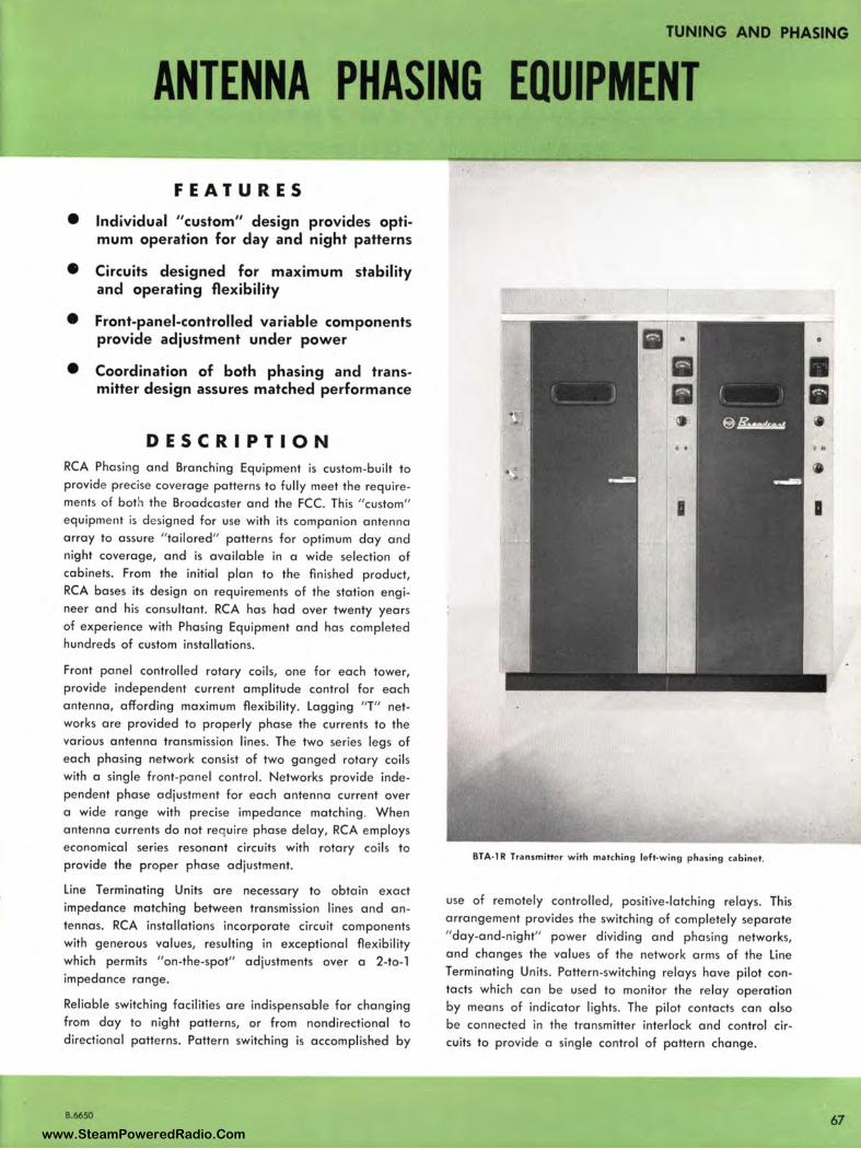
TUNING AND PHASING
ANTENNA PHASING EQUIPMENT
FEATURES
• Individual "custom" design provides optimum operation for day and night patterns
• Circuits designed for maximum stability and operating flexibil ity
• Front-panel-controlled variable components provide adjustment under power
• Coordination of both phasing and transmitter design assures matched performance
DESCRIPTION RCA Phasing and Branching Equipment is custom-built to provide precise coverage patterns to fully meet the requirements of both the Broadcaster and the FCC. This "custom" equipment is designed for use with its companion antenna array to assure "tailored" patterns for optimum day and night coverage, and is available in a wide selection of cabinets. From the initial plan to the finished product, RCA bases its design on requirements of the station engineer and his consultant. RCA has had over twenty years of experience with Phasing Equipment and has completed hundreds of custom installations.
Front panel controlled rotary coils, one for each tower, provide independent current amplitude control for each antenna, affording maximum flexibi lity. Lagging "T" networks are provided to properly phase the currents to the various antenna transmission lines. The two series legs of each phasing network consist of two ganged rotary coils with a single front-panel control. Networks provide independent phase adjustment for each antenna current over a wide range with precise impedance matching . When antenna currents do not require phase delay, RCA employs economical series resonant circuits with rotary coils to provide the proper phase adjustment.
Line Terminating Units are necessary to obtain exact impedance matching between transmission lines and an tennas . RCA installations incorporate circuit components with generous values, resulting in exceptional flexibility which permits " on-the-spot" adjustments over a 2-to- l impedance range.
Reliable switching facilities are indispensable for changing from day to night patterns, or from nondirectional to directional patterns. Pattern switching is accomplished by
B.6650
BTA-1 R Transmitte r with matching le ft-wi ng phasing cabinet.
use of remotely controlled, positive-latching relays. This arrangement provides the switching of completely separate "day-and-night" power dividing and phasing networks, and changes the values of the network arms of the Line Terminating Units. Pattern-switching relays have pilot contacts which can be used to monitor the relay operation by means of indicator lights. The pilot contacts can also be connected in the transmitter interlock and control circuits to provide a single control of pattern change.
67 www.SteamPoweredRadio.Com
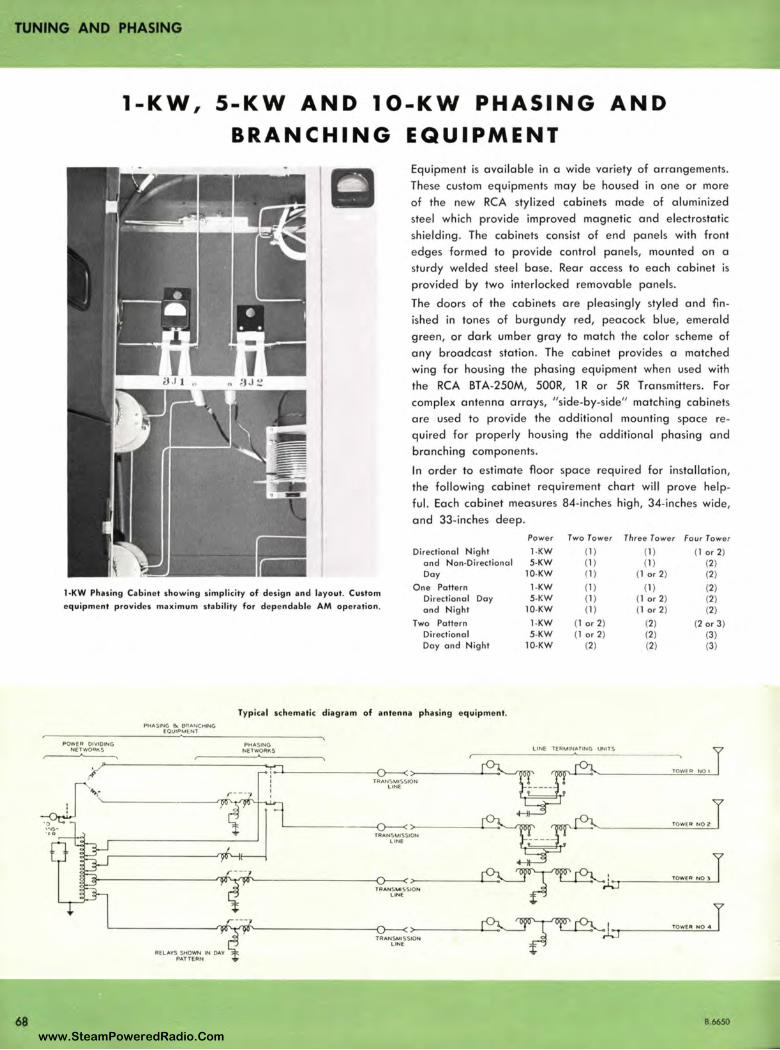
TUNING AND PHASING
68
1-KW, 5-KW AND 10-KW PHAS I NG AND BRANCHING EQUIPMENT
Equipment is available in a wide variety of arrangements. These custom equipments may be housed in one or more of the new RCA stylized cabinets made of aluminized steel which provide improved magnetic and electrostatic shielding . The cabinets consist of end panels with front edges form e d to provide control panels, mounted on a sturdy welded steel base. Rear access to each cabinet is provided by two interlocked removable panels.
The doors of the cabinets are pleasingly styled and fin ished in tones of burgundy red, peacock blue, emerald green, or dark umber gray to match the color scheme of any broadcast station. The cabinet provides a matched wing for housing the phasing equipme nt when used with the RCA BT A-250M, 500R, l R or 5R Transmitters. For complex antenna arrays, " side-by-side" matching cabinets are used to provide the additional mounting space required for properly housing the additional phasing and branching components.
In order to estimate floor space required for installation, the following cabinet requirement chart will prove helpful. Each cabinet measures 84-inches high, 34-inches wide, and 33-inches deep.
Po wer Two Tower Three To wer Fou r Tower
Directional Night I -KW (1) (1) (1 or 2) ond Non-Direct ional 5-KW (1) (1) (2) Doy 10-KW ( 1) ( l or 2) (2)
1-KW Phasing Cabinet showing simplicity of design and layout. Custom
equipment provides maximum stability for dependable AM operation.
One Pattern Directional and Night
1-KW Doy 5-KW
10-KW
(1) (1) (2) (1) (1 or 2) (2) (1) (1 or 2) (2)
POWER OIYIOING NETWOAI\S
~
PHASING &. BtlANCHING EQUIPMENl
Two Pattern Directional Doy and Night
Typical schematic diagram of an tenna phasing equipment.
PHASING NETWORKS
1-KW 5-KW
10-KW
)~' --------------'--------0--<'>------'--' --'700<'
TRAN SMISSION LINE
fRANSMISSION LINE
TAANSMI SSIOH LONE
TR AN SMISSION L INE
(1 or 2) (2) (2 o r 3) (1 or 2) (2) (3)
(2) (2) (3)
TOWER NO I
TOWER NO 2
' TOWE• NOlT ..._.__, _A..l_r-----~==-"--'-
TOWE• NO . T
8.6650
www.SteamPoweredRadio.Com
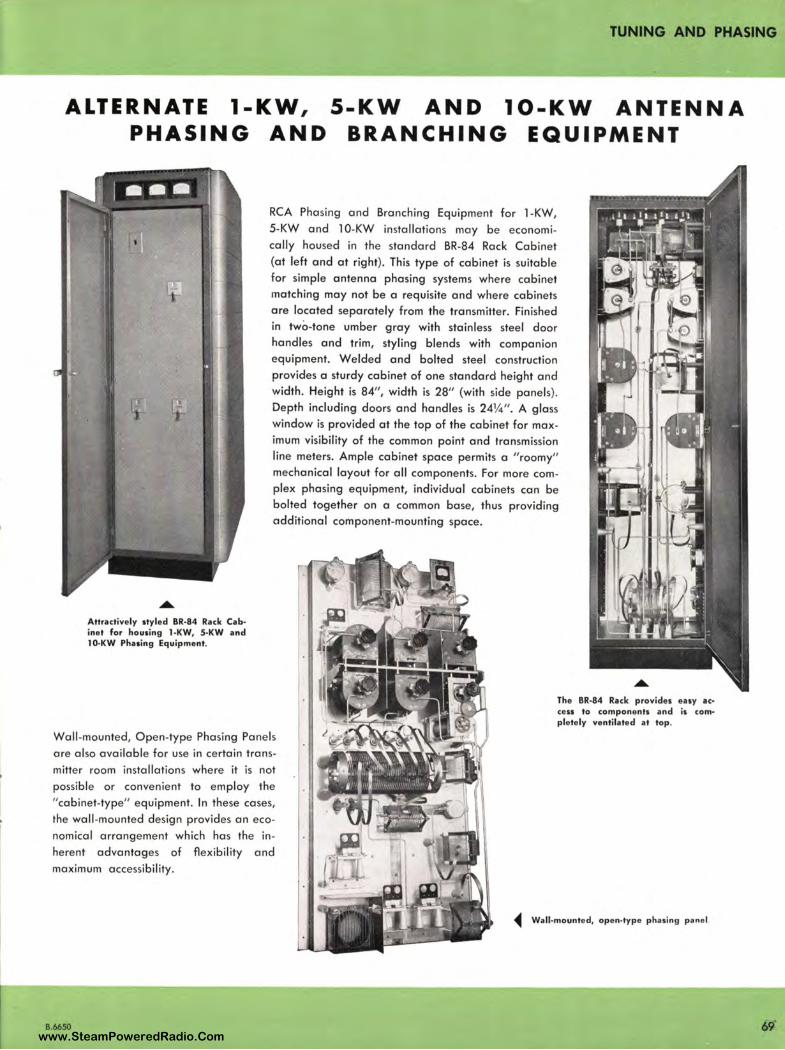
TUNING AND PHASING
ALTERNATE 1-KW, PHASING AND
5-KW AND 10-KW ANTENNA BRANCHING EQUIPMENT
Attractively styled BR-84 Rack Cabinet for housing 1-KW, 5-KW and 10-KW Phasing Equipment.
RCA Phasing and Branching Equipment for 1-KW, 5-KW and 10-KW installations may be economically housed in the standard BR-84 Rack Cabinet (at left and at right). This type of cabinet is suitable for simple antenna phasing systems where cabinet matching may not be a requisite and where cabinets are located separately from the transmitter. Finished in two-tone umber gray with stainless steel door handles and trim, styling blends with companion equipment. Welded and bolted steel construction provides a sturdy cabinet of one standard height and width. Height is 84", width is 28" (with side panels). Depth including doors and handles is 24¼". A glass window is provided at the top of the cabinet for maximum visibility of the common point and transmission line meters. Ample cabinet space permits a "roomy" mechanical layout for all components. For more complex phasing equipment, individual cabinets can be bolted together on a common base, thus providing additional component-mounting space.
The BR-84 Rack provides easy ac• cess to components and is com• plete ly ventilated at top.
Wall-mounted, Open-type Phasing Panels are also available for use in certain transmitter room installations where it is not possible or convenient to employ the "cabinet-type" eq uipment. In these cases, the wall-mounted design provides an economical arrangement which has the in herent advantages of flexibility and maximum accessibility.
• Wall-mounted, open-type phasing panel
B.6650 www.SteamPoweredRadio.Com
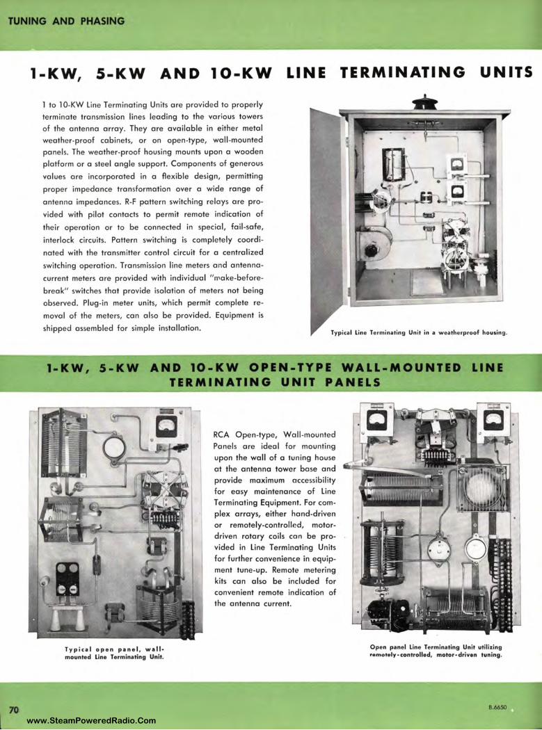
TUNING AND PHASING
70
1-KW, 5-KW AND 10-KW LINE TERMINATING UNITS
1 to 10-KW Line Terminating Units are provided to properly
terminate transmission lines leading to the various towers
of the antenna array. They are available in either metal
weather-proof cabinets, or on open-type, wall-mounted
panels. The weather-proof housing mounts upon a wooden
platform or a steel angle support. Components of generous
values are incorporated in a flexible design, permitting
proper impedance transformation aver a wide range of
antenna impedances. R-F pattern switching relays are pro
vided with pilot contacts to permit remote indication of
their operation or to be connected in special, fail-safe,
interlock circuits. Pattern switching is completely coordi
nated with the transmitter control circuit for a centralized
switching operation. Transmission line meters and antenna
current meters are provided with individual " r,,ake-before
break" switches that provide isolation of meters not being
observed. Plug-in meter units, which permit complete re
moval of the meters, can also be provided. Equipment is
shipped assembled for simple installation. Typical l ine Terminating Unit in a weatherproof housing .
1-KW, 5-KW AND 1O-KW OPEN-TYPE WALL-MOUNTED LINE TERMINATING UNIT PANELS
Typical open panel, wall• mounted line Terminating Unit.
RCA Open-type, Wall -mounted
Panels are ideal for mounting
upon the wall of a tuning house
at the antenna tower base and
provide maximum accessibility
for easy maintenance of Line Terminating Equipment. For complex arrays, either hand-driven
or remotely-controlled, motordriven rotary coils can be pro
vided in Line Terminating Units
for further convenience in equipment tune-up. Remote metering
kits can also be included for
convenient remote indication of the antenna current.
Open panel line Terminating Unit utilizing remotely- controlled, motor• driven tuning.
B.6650
www.SteamPoweredRadio.Com
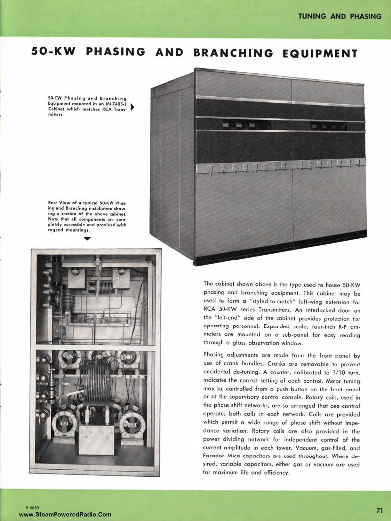
50-KW PHASING
B.6650
SO-KW P ha s i n g a n d B r a n c h i n g Equipment mounted in an Ml-748S-J • Cabinet which matches RCA Trans· mitters.
Rear View of a typical SO-KW Phasing and Bra nchi ng insta llation showing a section of the above cabinet. Note that all components are com• pletely accessible and provided with rugged mo untings.
AND
TUNING AND PHASING
BRANCHING EQUIPMENT
The cabinet shown above is the type used to house 50-KW phasing and branching equipment. This cabinet may be used to form a " styled-to-match" left-wing extension for RCA 50-KW series Transmitters. An interlocked door on the "left-end" side of the cabinet provides protection fo ~ operating personnel. Expanded sca le, four-inch R-F ammeters are mounted on a sub-panel for easy reading through a glass observation window.
Phasing adjustments are made from the front panel by use of crank handles. Cranks are removable to prevent accidental de-tuning. A counter, calibrated to 1/1 0 turn, indicates the correct setting of each control. Motor tuning may be contro lled from a push button on the front panel or at the supervisory control console. Rotary coils, used in the phase shift networks, are so arranged that one control operates both coils in each network. Coils are provided which permit a wide range of phase shift without impedance variation. Rotary coils are also provided in the power dividing network for independent control of the current amplitude in each tower. Vacuum, gas-filled, and Faradon Mica capacitors are used throughout. Where desired, variable capacitors, either gas or vacuum are used for maximum life and efficiency.
71 www.SteamPoweredRadio.Com
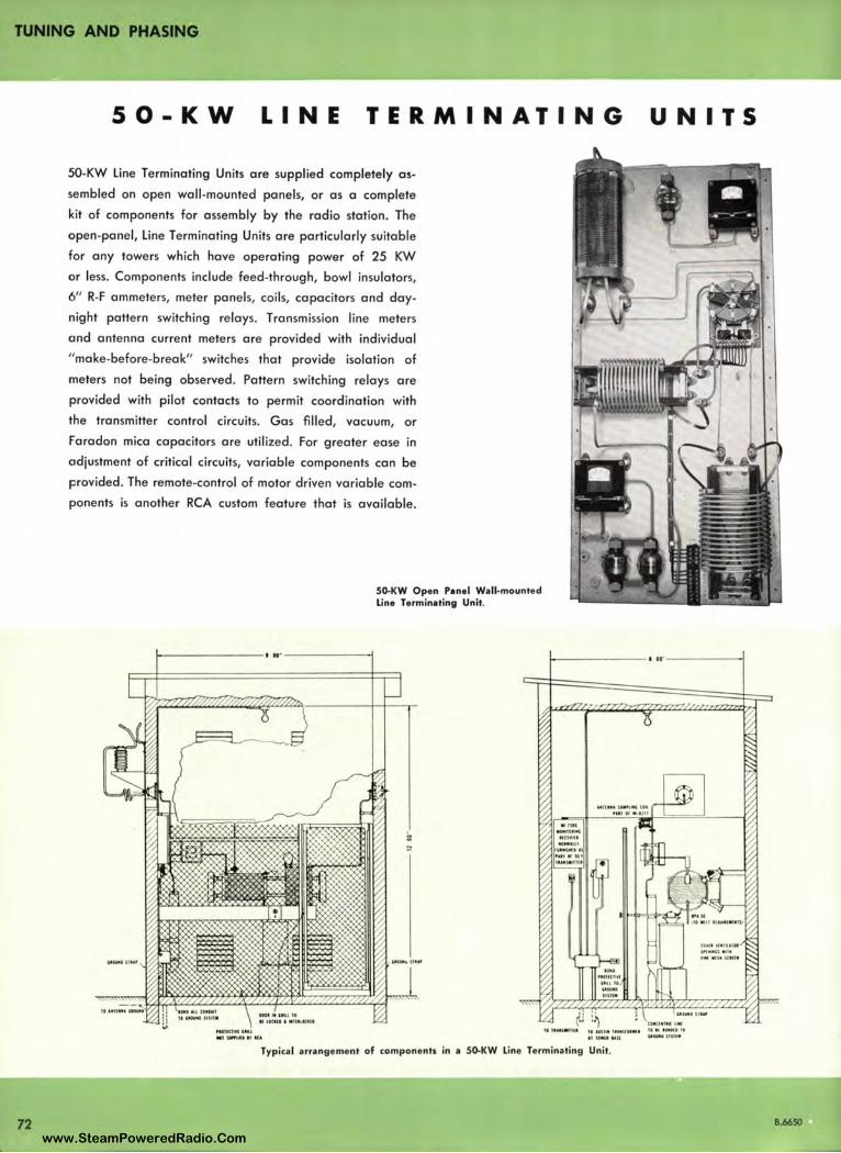
TUNING AND PHASING
5 0-KW LINE TERMINATING
50-KW Line Terminating Units are supplied completely as
sembled on open wall-mounted panels, or as a complete
kit of components for assembly by the radio station. The
open-panel, Line Terminating Units are particularly suitable
for any towers which have operating power of 25 KW
or less. Components include feed -through, bowl insulators,
6" R-F ammeters, meter panels, coils, capacitors and day
night pattern switching relays. Transmission line meters
and antenna current meters are provided with individual
"make-before-break" switches that provide isolation of
meters not being observed. Pattern switching relays are
provided with pilot contacts to permit coordination with
the transmitter control circuits. Gas filled, vacuum, or
Faradon mica capacitors are utilized . For greater ease in
adjustment of critical circuits, variable components can be
provided. The remote-control of motor driven variable com
ponents is another RCA custom feature that is available.
50-KW Open Panel Wall-mounted Line Termin•ting Unit.
UN ITS
~------- • ... _____ _ ,-.- -----• 11·----- -1
72
,..11ui,1 u u • I SIWUI. fl KA
II lt.-.S-1111 ti •'11• IU J11$1tUIU
11 11•11 " "
Typical arrangement of components in a 50-KW Line Terminating Unit.
B.6650
www.SteamPoweredRadio.Com
wigfi
Stolen 2 Line Transparent
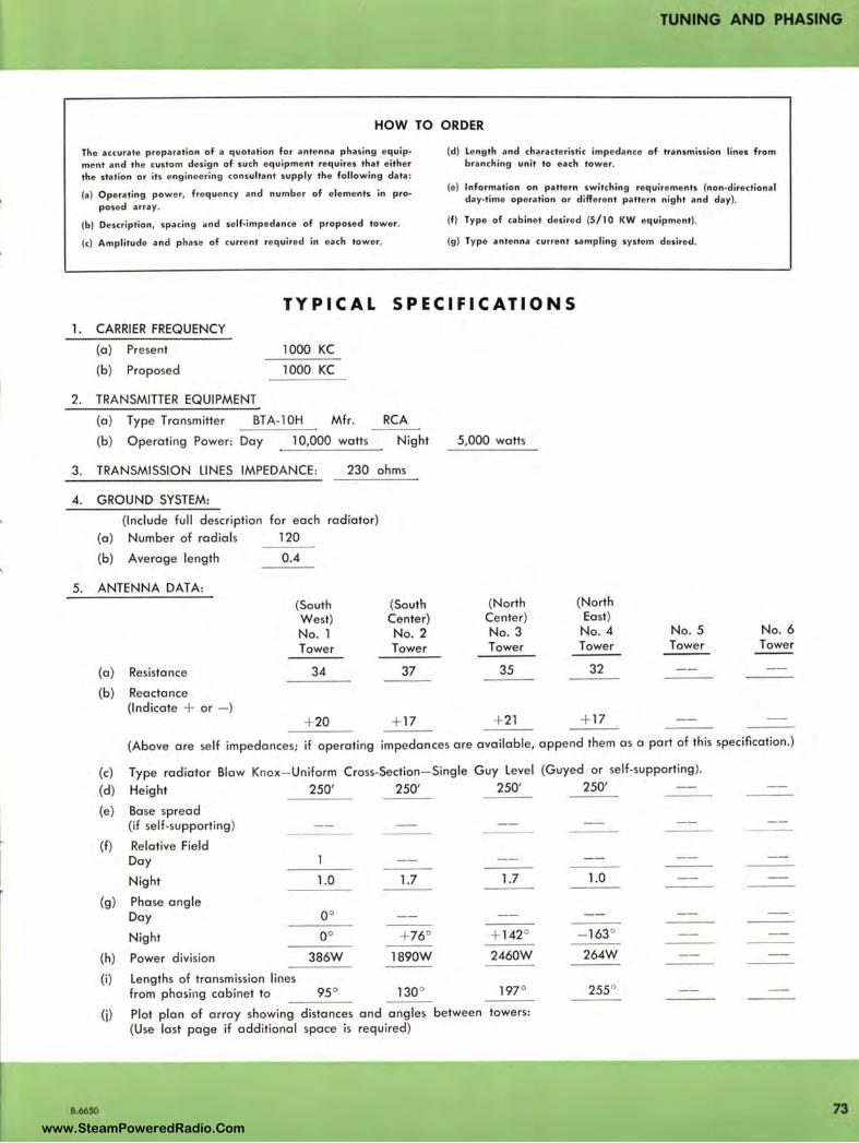
~
I
TUNING AND PHASING
HOW TO ORDER
The accurate preparation of a quotation for antenna phasing equipment and the custom design of such equipment requ ires that either the station or its engineering consultant supply the following data :
{a) Operating power, frequency and number of elements in pro• posed array .
(b) Description, spacing and self-impedance of proposed tower.
(c) Amplitude and phase of current required in each tower.
(d) length and characteristic impedance of transmission lines from branching unit to each tower.
(e) Information on pattern switching requirements (non-directional day-time operation or differen t pattern night and day).
(f) Type of cabinet desired (S/10 KW equipment).
(g) Type antenna current sampling system desired .
TY PICAL SPECIFICATIONS 1. CARRIER FREQUENCY
(a) Present
(b) Proposed
2. TRANSMITTER EQUIPMENT
1000 KC
1000 KC
(a) Type Transmitter BTA-l0H Mfr. RCA
3.
4.
5.
(b) Operating Power: Day 10,000 watts Night
TRANSMISSION LINES IMPEDANCE: 230 ohms
GROUND SYSTEM:
(Include full description (a) Number of radials
(b) Average length
ANTENNA DATA:
(a) Resistance
(b) Reactance (Indicate + or - )
for each radiator)
120
0.4
(South West) No. 1 Tower
34
+ 20
(South Center) No. 2 Tower
37
+ 17
5,000 watts
(North (North Center) East) No. 3 No. 4 No. 5 No. 6 Tower Tower Tower Tower
35 32
+ 21 + 17
(Above ore self impedances; if operating impedances ore available, append them as a part of this specification.)
(c) Type radiator Blow Knox- Uniform Cross-Section- Single Guy Level (Guyed or self-supporting).
(d) Height 250' 250' 250' 250'
(e) Base spread (if self-supporting)
(f) Relative Field Doy l
Night 1.0 1.7 1.7 1.0
(g) Phase angle Day oo Night oo + 76° + 142° - 163°
(h) Power division 386W 1890W 2460W 264W
(i) Lengths of transmission lines from phasing cabinet to 95° 130° 197° 255 °
(j) Plot plan of array showing distances and angles between towers: (Use last page if additional space is required)
8.6650 73 www.SteamPoweredRadio.Com
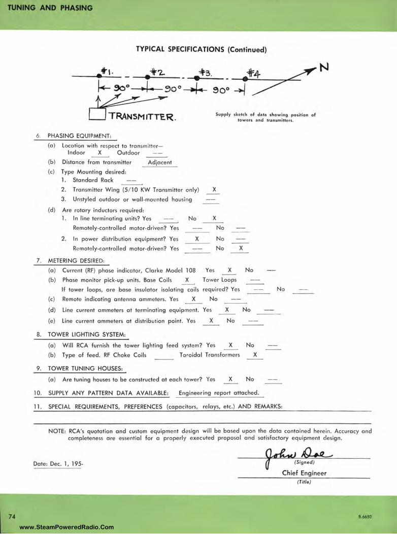
TUNING AND PHASING
74
TYPICAL SPECIFICATIONS (Continued)
• i'-'2.. • 43 .
. ,. ~0°4 90°
TRANSMtTTc.R. Supply sketch of data showing position of towers and transmitte rs .
6 . PHASING EQUIPMENT:
(a) location with res pect to tronsm iltP. r-lndaor X Outdoor
(b) Distance from transmitter
{c) Type Mounting desired :
l. Standard Rack
Adjacent
2. Transmitter Wing (5 / 10 KW Transmitter only) X
3. Unstyled outdoor or wall -mo unted housing
(d ) Are rotary inductors required :
l. In line terminating units? Yes No
Remotely-controlled motor-dr iven? Yes
2. In power distribution equipment? Yes
Re mote ly-controlled motor-driven? Yes
7 . METERING DESIRED:
(a ) Curre nt (RF) phase in dicator, Clarke Mode l l 08
(b) Phase monitor pick-up units . Base Coils X
X
X
No
No
No
Yes X
Tower loops
X
If tower loops, ore base insulator isolating coils require d? Yes
Remote indicating antenna ammete rs. Yes X No (c)
(d) Line current ammeters at terminating equipment. Yes X
(e) Line current ammeters at distribution point. Yes X No
8. TOWER LIGHTING SYSTEM:
No
No
(a) Will RCA furnish the tower lighting feed system? Yes X No
(b) Type of feed. RF Choke Coils Toroidal Transforme rs X
9. TOWER TUNING HOUSES:
(a ) Are tuning houses to be constructed at each towe r? Yes X No
10. SUPPLY ANY PATTERN DATA AVAILABLE: Engineering report attached.
No
11 . SPECIAL REQUIREMENTS, PREFERENCES (capacitors, re lays, etc.) AND REMARKS:
NOTE: RCA's quotation and custom equipment dasign will be based upon the data contained here in . Accuracy and completeness are essential for a properly executed proposal and satisfactory equipment design.
Date: Dec. 1, 195-
Chief Engineer (Title )
8.6650
www.SteamPoweredRadio.Com
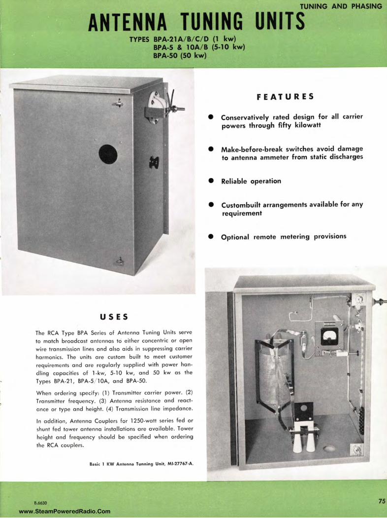
TUNING AND PHASING
ANTENNA TUNING UNITS TYPES BPA-21A/ B/ C/ D (1 kw)
BPA-5 & l0A/ B (5-10 kw) BPA-50 (50 kw)
USES
The RCA Type BPA Series of Antenna Tuning Units serve
to match broadcast ante nnas to either concentric or open
wire transmission lines and also aids in suppressing carrier
harmonics. The units ore custom built to meet customer
requireme nts and are regularly supplied with power han
dling capacities of 1-kw, 5-10 kw, and 50 kw as the
Types BPA-21 , BPA-5/ l 0A, and BPA-50.
When ordering specify: (l ) Transmitter carrier power. (2)
Transmitter frequency. (3) Antenna resistance and react
once or type and height. (4) Transmission line impedance.
In addition, Antenna Couplers for 1250-watt series fed or
shunt fed tower antenna installations are available. Tower
height and fre q uency should be specified when ordering
the RCA couplers.
Basic 1 KW Anten na Tunnin g Unit, Ml-27767-A.
B.6630
FEATURES
• Conservatively rated design for all carrier powers through fifty kilowatt
• Make-before-break switches avoid damage to antenna ammeter from static discharges
• Reliable operation
• Custombuilt arrangements available for any requirement
• Optional remote metering provisions
75
www.SteamPoweredRadio.Com
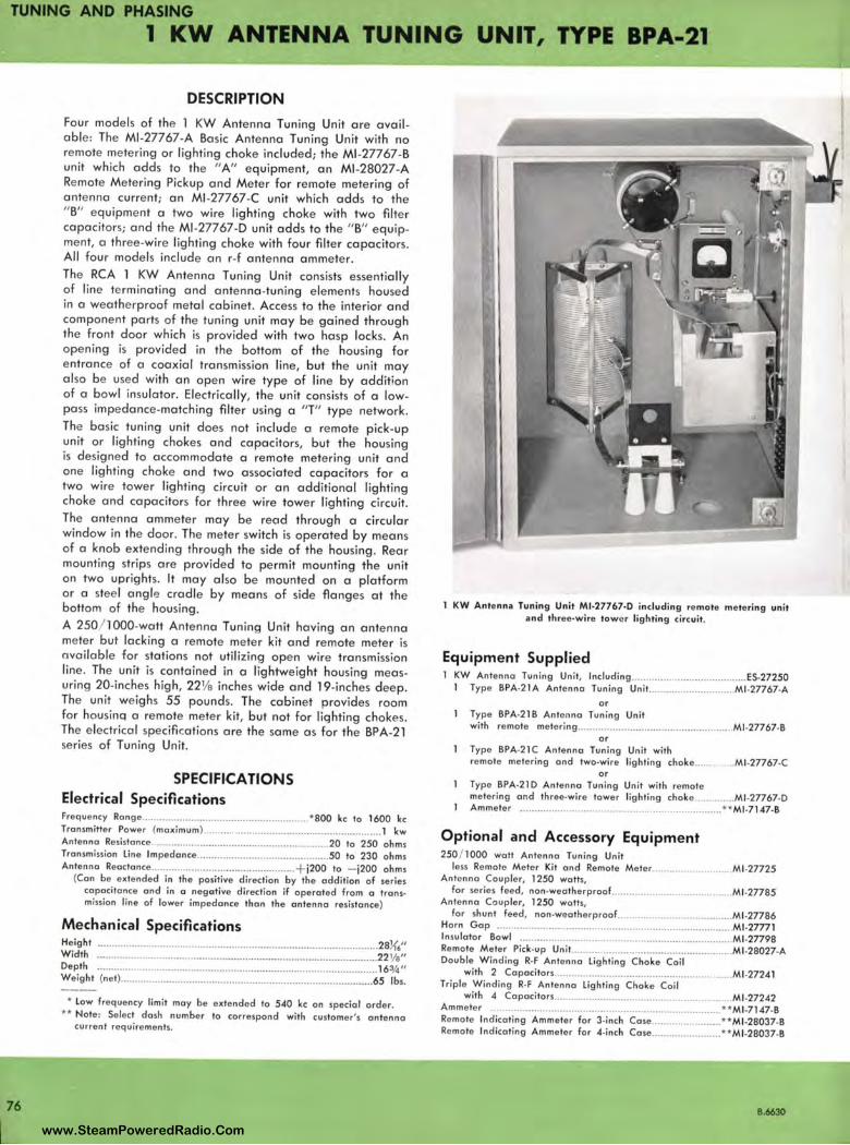
TUNING AND PHASING 1 KW ANTENNA TUNING UNIT, TYPE BPA-21
76
DESCRIPTION Four models of the 1 KW Antenna Tuning Unit are available: The Ml -27767-A Basic Antenna Tuning Unit with no remote metering or lighting choke included; the Ml-27767-B unit which adds to the " A" equipment, an Ml-28027-A Re mote Metering Pickup and Meter for remote metering of antenna current; an Ml -27767-C unit which adds to the " B" equipment a two wire lighting choke with two filter capacitors; and the Ml -27767-O unit adds to the "B" equipment, a three-wire lighting choke with four filter capacitors. All four models include an r-f antenna ammeter. The RCA 1 KW Ante nna Tuning Unit consists essentially of line terminating and antenna-tuning elements housed in a weatherproof metal cabinet. Access to the interior and component parts of the tuning unit may be gained through the front door which is provided with two hasp locks. An opening is provided in the bottom of the housing for e ntrance of a coaxial transmission line, but the unit may al so be use d with an open wire type of line by addition of a bowl insulator. El ectrically, the unit consists of a lowpass impedance-matching filter using a "T" type network . The basic tuning unit does not include a re mote pick-up unit or lighting chokes and capacitors, but the housing is designed to accommodate a remote mete ring unit and one lighting choke and two associated capacitors for a two wire towe r lighting circuit or an additio nal lighting choke and capacitors for three wire tower lighting circuit. The ante nna ammeter may be read through a circular window in the door. The meter switch is operated by means of a knob extending through the side of the housing . Rear mounting strips are provided to permit mounting the unit on two uprights. It may also be mounted on a platform or a stee l angle cradle by means of side flanges at the bottom of the housing. A 250/ 1000-watt Antenna Tuning Unit having an antenna meter but lacking a re mote meter kit and remote meter is available for stations not utilizing open wire transmission line . The unit is contained in a lightweight housing measuring 20-inches high, 221/e inches wide and 19-inches deep. The unit weighs 55 pounds. The cabinet provides room for housina a re mote meter kit, but not for lighting chokes. The e lectrical specifications are the same as for the BPA-21 se ries of Tun ing Unit.
SPECIFICATIONS Electrical Specifications Frequency Ron ge .......................................................... *800 kc lo 1600 kc Transmitter Power (maxim um ) ............................................................ .. 1 kw Antenna Resistance ..................................... ............ ....... ..... 20 to 250 ohms Transmission Line lm pedonce .............................................. 50 to 230 ohms Antenna Reoctonce ............ ..... ... .............................. + j200 to - j200 oh ms
(Con be extended in th e positive direction by th e addition of series capacitance and in a negGJtive direction if operated from a transmissio n line of lower impedance than the antenna resistance)
Mechanical Specifications Height .......................... ......... .... ............................ .. ....................... .. .. .. 28){/' W idth ......... .... ........................... ........... ............ ... ............. .. ................ . 22 1/a" Depth .................................................................................................. 16¾" Weight (net) ............................................................................... ......... 65 lbs.
* Low frequency limit may be extended lo 540 kc on specia l order. ** Note: Select dash number to correspond with customer's antenna
current requirements.
KW Ante nna Tuning Unit Ml-27767-0 includi ng rem ote metering unit and three-wire tow e r lighti ng circuit.
Equipment Supplied KW Antenna Tuning Unit, Including ....................................... ES-27250 1 Type BPA-21A Antenna Tuning Unit ................. .. .......... Ml -27767•A
or Type BPA-21 B Anten na Tuning Unit with remote metering .. .............. .... .. ... ............................. Ml -27767-B
o r Type BPA-21C Antenna Tuning Unit with remote metering and two-wire lighting choke....... . ... Ml -27767-C
or Type BPA-210 Antenna Tuning Un it with re mote metering and three-wire tower lighting choke .............. Ml -27767-0 Ammeter .. ..... ................................................... ...... ..... **Ml -7147-B
Optional and Accessory Equipment 250 / 1000 watt Antenn a Tuning Unit
less Remote Meter Kit and Re mote Meter ........................... Ml .27725 Antenna Coupler, 1250 watts,
for series feed, non-wea th erproof.. ........................................ Ml -27785 Antenna Coupler, 1250 watts,
for shunt feed , non-weatherproof ........................................ Ml -27786 Ho rn Gap ................................................... ..... ................ ......... Ml-27771 Insulator Bowl .......................................................................... Ml -27798 Re mote Meter Pick-up Un it ......... ................... ............... ...... ....... Ml-28027-A Double W inding R-F Antenna Lig hting Choke Coil
with 2 Capacitors ... ........... .......... .............................•.. ...... Ml -27241 Triple Winding R. f Antenna light ing Choke Coil
with 4 Capacitors ............................................................ Ml -27242 Am meter ......... .. .. ...... ................................................... .......... **Ml-7147-B Remote Indicating Ammeter for 3-inch Case ... ..................... **Ml -28037•8 Remote Ind icating Ammeter for 4-inch Case .. ..... .. ............... **Ml -28037-B
B.6630
www.SteamPoweredRadio.Com
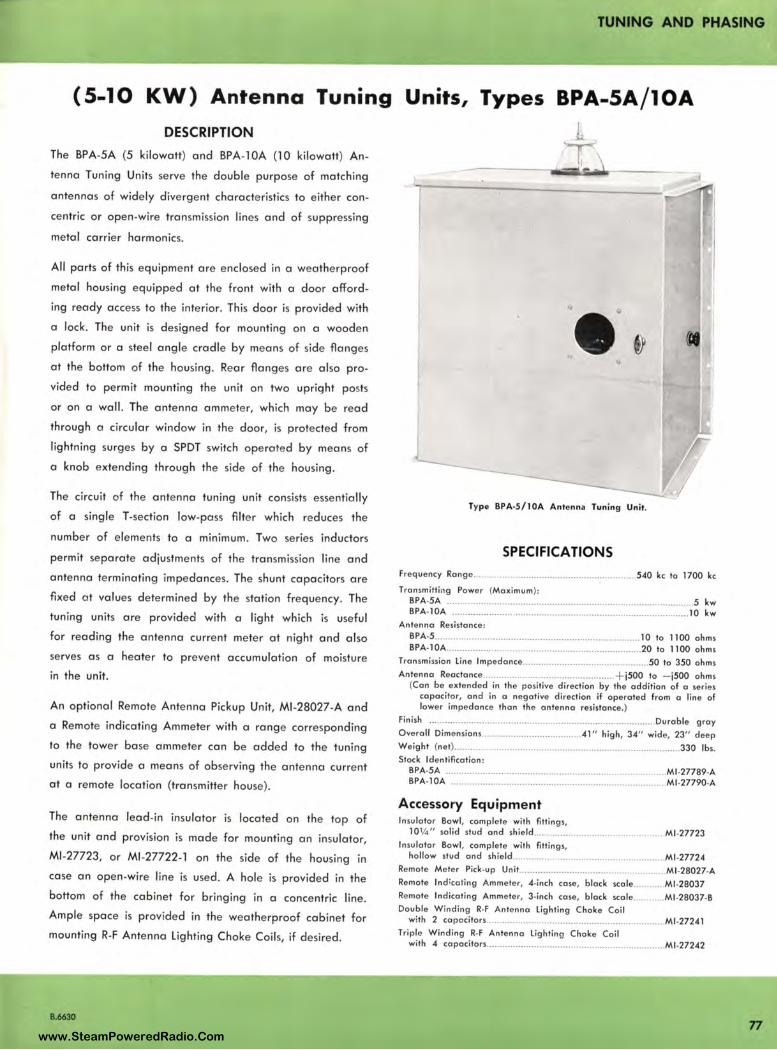
TUNING AND PHASING
(S-10 KW) Antenna Tuning Units, Types BPA-SA/lOA DESCRIPTION h
The BPA-5A (5 kilowatt) and BPA-1 OA (l O kilowatt) An
tenna Tuning Units serve the double purpose of matching
antennas of widely dive rgent characte ristics to either con
centric or open-wire transmission lines and of suppressing
metal carrier harmonics.
All parts of this equipme nt are enclosed in a weatherproof
metal housing equipped at the front with a door afford
ing ready access to the inte rior. This door is provided with
a lock. The unit is designed for mounting on a wooden
platform or a steel angle cradle by means of side flanges
at the bottom of the housing . Rear flanges are also pro
vided to permit mounting the unit on two uprig ht posts
or on a wall . The antenna ammete r, which may be read
thro ugh a circular window in the door, is protected from
lightning surges by a SPDT switch ope ra ted by means of
a knob extending through the side of the housing.
The circuit of the ante nna tuning unit consists esse ntially
of a single T-section low-pass filte r which reduces the
number of elements to a minimum. Two series inductors
permit se parate adjustments of the transmission line and
antenna terminating impedances . The shunt capacitors are
fixe d at va lues determined by the station fre quency. The
tun ing units are provided with a light which is useful
for reading the antenna current meter at night and also
serves as a heater to prevent accum ulation of moisture
in the unit.
An optional Remote Antenna Pickup Unit, Ml -28027-A and
a Remote indicating Ammeter with a range corresponding
to the tower base ammeter can be added to the tuning
units to provide a means of observing the antenna curre nt
at a remote location (transmitter house) .
The antenna lead-in insulator is located on the top of
the unit and provision is made for mounting an insulator,
Ml -27723, or Ml-27722-1 on the side of the housing in
case an open-wire line is used. A hole is provided in the
bottom of the cabinet for bringing in a concentric line .
Ample space is provided in the weatherproof cabinet for
mounting R-F Antenna lighting Choke Coils, if desired .
B.6630
Type BPA·S/ lOA Ante nn a Tun ing Un it.
SPECIFICATIONS Frequ ency Ra nge..... .. . ................................................. 540 kc ta 1700 kc
Transmitti ng Power (Maximum ): BPA-SA .................................................................................... .......... 5 kw BPA-l0A ....................................................................... ......... ......... 10 kw
Antenna Res istance: BPA-5 .................. ... .............................. .......................... 10 to 1100 ohms BPA-l0A. ............. ............................................................ 20 to 1100 ohms
Transmission Lin e lmpedance ................................................ 50 to 350 ohms Antenna Reactance ........................ .................... .... .. + j500 to - j500 ohms
(Can be extended in th e positive direction by the addition of a se ries capacito r, and in a negat ive di rection if ope rated from a line of lower impedance than th e a ntenna resistance.)
Finish ..................................................................................... Du rable g ray Overall Dimensions ..................................... 41 " high , 34" wide, 23" dee p Weight {net)............................................... ................ . .................. 330 lbs. Stock Identification :
BPA-5A ............................................................................... Ml -27789-A 8PA-10A .............. ................................................................. Ml-27790-A
Accessory Equipment In sulator Bowl, comple te with fitt ings,
1 0¼" solid stud and shie ld .............. .. .. ... ... . ............ Ml -27723 Insulator Bowl , comple te with fitting s,
hollow stud and sh ie ld ......................................................... Ml-27724 Remote Mete r Pick-up Unit ............ .. .......................................... Ml -28027-A Remote lnd ;cat ing Ammete r, 4-inch case , black scale ............ Ml -28037 Remote Indicat ing Ammeter, 3-inch case, black scale ............ Ml -28037-B Double W indin g R-F Antenna light ing Choke Coil
with 2 capa citors ................................................................. Ml -27241 Triple Winding R-F Antenna lighting Choke Coil
with 4 capacitors ................................................................... Ml -27242
77 www.SteamPoweredRadio.Com
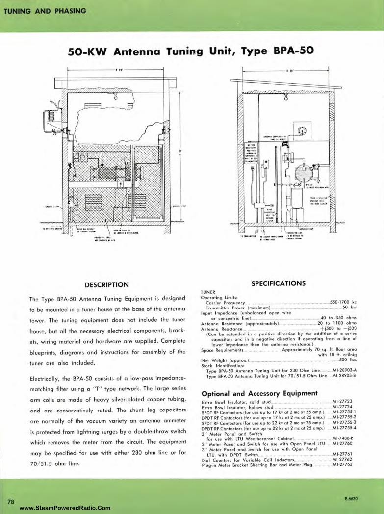
TUNING AND PHASING
50-KW Antenna Tuning Unit, Type BPA-50
78
t--------- ' 11·------ --<
" tllt! IU U U
•'"""-"'" '"
DESCRIPTION
The Type BPA-50 Antenna Tuning Equipment is designed
to be mounted in a tuner house at the base of the antenna
tower. The tuning equipment does not include the tuner
house, but all the necessary electrical components, brack
ets, wiring material and hardware are supplied . Complete
blueprints, diagrams and instructions for assembly of the
tuner are also included.
Electrically, the BPA-50 consists of a low-pass impedance
matching filter using a "T" type network. The large series
arm coils are made of heavy silver-plated copper tubing,
and are conservatively rated. The shunt leg capacitors
are normally of the vacuum variety an antenna ammeter
is protected from lightning surges by a double-throw switch
which removes the meter from the circuit. The equipment
may be specified for use with either 230 ohm line or for
70/ 51.5 ohm line .
1--------- 1 11·-------l
II H "II IIHSU tlllf l U IIWlt 1,UI UW .. USII .
SPECIFICATIONS TUNER Operating Limits :
Carrier Freque ncy ..................... .. ........................................... 550-1700 kc
Transmitter Power (maximum) .............................................. .......... 50 kw Input Impedance (unbalanced open •.¥ire
or concentric line) ...................................... .......... .. .... 40 to 350 ohms
Antenna Resistance (approximately) .. .... .. ..................... 20 to 1100 ohms
Antenna Reactance ............................................................ + j500 to - j500
(Can be extend ed in a positive direction by the addition of a series
capacitor; ond in a negative direction if operating from a line of
lower impedance than the antenna resistance.) Space Requirements ......................... ..... Approximate ly 70 sq. ft . floor areo
with l O ft . cei lnig
Net Weight (approx .) ...... ............. ... ... .................. ........................... 500 lbs.
Stock Identificat ion : Type BPA·50 Antenna Tuning Unit for 230 Ohm Line .......... Mf .28903-A
Type BPA-50 Antenna Tuning Unit for 70 / 51.5 Ohm Line .... Ml -2B903-B
Optional and Accessory Equipment Extra Bowl In sulator, so lid stud ......................................... . .. Ml -27723
Extra Bowl Insulator, hollow stud ............................................ Ml -27724
SPDT RF Conlaclors (for use up to 17 kv at 2 me at 25 amp.) Ml -27755-1
DPDT RF Contactors (for use up to 17 kv at 2 me at 25 omp.) .. Ml -27755-2
SPDT RF Contactors (for use up to 22 kv at 2 me at 25 omp.) ... Ml -27755•3
DPDT RF Contactors (for use up to 22 kv at 2 me at 25 amp.) . Ml -27755-4
3" Mete r Pane l and Sw' tch for use with LTU Weatherproof Cobine t .............................. Ml -7486-B
3" Meter Pane l and Switch for use with Open Pane l LTU ..... Ml-27760
3" Meter Pane l and Switch for use with Open Panel LTU with DPDT Switch .......................................................... Ml-27761
Dial Counters for Va riable Coil lnductors .............................. Ml -27762
Plug-in Metar Brocket Shorting Bar and Meter Plug ................ Ml -27763
B.6630
www.SteamPoweredRadio.Com
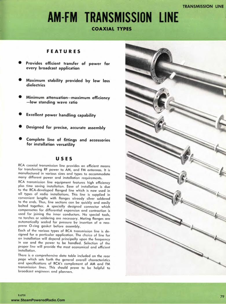
AM-FM TRANSMISSION [INE COAXIAL TYPES
FEATURES
• Provides efficient transfer of power for every broadcast application
• Maximum stability provided by low loss dielectrics
• M inimum attenuation- maximum efficiency - low standing wave ratio
• Excellent power handling capability
• Designed for precise, accurate assembly
• Complete line of fittings and accessories for installation versatil ity
USES RCA coaxial transmission line provides an efficient means for transferring RF power to AM, and FM antennas. It is manufactured in various sizes and types to accommodate many different power and installation requirements. RCA transmission line equipment features high efficiency plus time saving installation. Ease of installation is due to the RCA-developed flanged line which is now used in all types of radio installations. This line is supplied in convenient lengths with flanges already silver soldered to the ends. Thus, line sections can be quickly and easily bolted together. A specially designe d connector which compensates for differential expansion and contraction is used for joining the inner conductors. No special tools, no torches or soldering are necessary. Mating flanges are automatically seale d for pressure by insertion of a neoprene 0-ring gasket before assembly. Each of the various types of RCA transmission line is designed for a particular application. The choice of line for an installation will depend principally upon the frequency in use and the power to be handled . Selection of the proper line will provide the most economical and efficient installation. There is a comprehensive data table included on the rear page which sets forth the general overall ch_aracteristics and specifications of RCA's complement of AM and FM transmission lines. This should prove to be helpful to broadcast engineers and planners.
8.6700
TRANSMISSION LINE
79 www.SteamPoweredRadio.Com

TRANSMISSION LINE
3/s" 72-OHM SOFT COPPER LINE AND FITTINGS, Ml-193O6
80
ADAPTER Ml -19306-7
COUPLING Ml -19306-3
DESCRIPTION
END SEAL Ml-19306-6
RCA 3/e" Beaded Steatite Transmission Line, Type Ml -19306, is a soft copper 72-ohm coaxial line designed for uses where the power and frequency to be handled ore rela tively low, and where line efficiency is not too important a factor. This type line is widely used to carry phase sampling voltages for directional AM arrays, to feed frequency measuring equipment, etc. It is also used in mobile and aircraft communication installations. This solder-type, soft line is available with a complete complement of couplings, adapters, end seals, clamps, and reducers. The line lends itself readily to bending around obstructions and therefore requires no elbows.
Ml-19306-1 TRANSMISSION LINE This line is furnished to specified length on 36"-diameter reels which contain up to 250 feet, or on larger returnable reels which contain up to 5000 feet. The coils ore hermetically sealed. Orders should specify which is desired . Insulators ore spaced l ¾" apart allowing a bending radius of 8" without shorting or loss of concentricity. Capable of handling 250 w. nominal and l kw maximum power.
Ml-19306-2 STRAIGHT COUPLING This item includes solder type inner and outer conductors.
TRANSMISSION LINE Ml-19306-1
REDUCER Ml -19306-4
,___ COUPLING Ml -19306-2
CLAMP Ml -19306-8
Ml-19306-3 COUPLING (Straight Gas Servicing) Outer conductor has two 1/e" IPS ports for gos admission with pipe plugs. Item includes solder type inner conductor.
Ml-19306-4 REDUCER COUPLING Used for reducing ½" diameter Ml-19309 hard drawn transmission line to 3/s" diameter soft line for soldering. Includes 2 steel locking plates for mounting to flat surface.
Ml-19306-5 END SEAL WITH GAUGE AND VALVE Solder type including two valves for gas admission with pipe plugs, furnished with nut for clomping to mounting surface.
Ml-19306-6 END SEAL Solder type including two 1/e" IPS ports for gas admission with pipe plugs. Furnished with nut for clamping to mounting surface.
Ml-19306-7 ADAPTER Used for coupling RG l l / U Cable when used with End Seals Ml -19306-5 or Ml -19306-6 to Type UG-21U Plug.
Ml-19306-8 CLAMP Used for clamping 3/e" diameter line. Has 2 holes for number l O screws. Mount one clamp approximately every 4 feet .
8.6700
www.SteamPoweredRadio.Com
wigfi
Stolen 2 Line Transparent
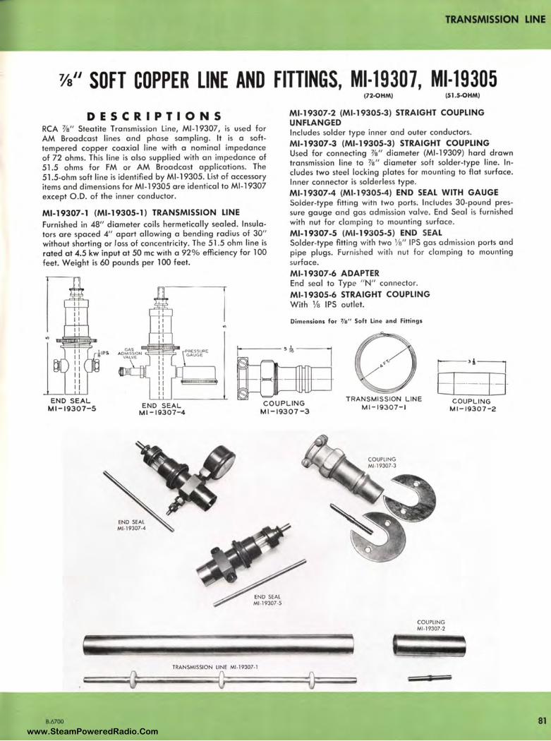
TRANSMISSION LINE
3/s" SOFT COPPER LINE AND FITTINGS, Ml-193O7, Ml-193O5
DESCRIPTIONS RCA 3/s" Steatite Transmission Line, Ml -19307, is used for AM Broadcast lines and phase sampling. It is a softtempered copper coaxial line with a nominal impedance of 72 ohms. This line is also supplied with an impedance of 51.5 ohms for FM or AM Broadcast applications. The 51.5-ohm soft line is identified by Ml-19305. List of accessory items and dimensions for Ml-19305 are identical to Ml -19307 except O.D. of the inner conductor.
Ml-19307-1 (Ml-19305-1) TRANSMISSION LINE Furnished in 48" diameter coils hermetically sealed. Insulators are spaced 4" apart allowing a bending radius of 30" without shorting or loss of concentricity. The 51 .5 ohm line is rated at 4.5 kw input at 50 me with a 92% efficiency for 100 feet. Weight is 60 pounds per 100 feet.
(72-0HM) (51.S-OHM)
Ml-19307-2 (Ml-19305-3) STRAIGHT COUPLING UNFLANGED Includes solder type inner and outer conductors.
Ml-19307-3 (Ml-19305-3) STRAIGHT COUPLING Used for connecting 'l's'' diameter (Ml-19309) hard drawn transmission line to 3/a" diameter soft solder-type line. Includes two steel locking plates for mounting to flat surface. Inner connector is solderless type.
Ml-19307-4 (Ml-19305-4) END SEAL WITH GAUGE Solder-type fitting with two ports. Includes 30-pound pressure gauge and gas admission valve. End Seal is furnished with nut for clamping to mounting surface.
Ml-19307-5 (Ml-19305-5) END SEAL Solder-type fitting with two 1/s" IPS gas admission ports and pipe plugs. Furnished with nut fo r clamping to mounting surface. Ml-19307-6 ADAPTER End seal to Type " N" connector.
Ml-19305-6 STRAIGHT COUPLING With 1/s IPS outlet.
Dimensions for 7/ e" Soft Line and fittings
r ·' 1
El----7---l-END SEAL
Ml-19307-5 END SEAL Ml-19307-4
COUPLING Ml-19307-3
TRANSMISSION LINE Ml-19307-1
COUPLING Ml-19307-2
8.6700
END SEAL Ml-19307-4
TRANSMISSION LINE Ml -19307-1
COUPLING Ml-19307-2
81 www.SteamPoweredRadio.Com
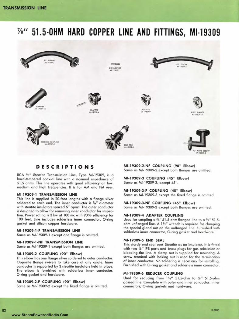
TRANSMISSION LINE
3/a" 51.5-0HM HARD COPPER LINE AND FITTINGS, Ml-19309
82
REDUCER COUPLING Ml -19309-6
ADAPTER Ml-19309-4
DESCRIPTIONS
c:=CONNECTOR Ml-19309-11
RCA 3/a" Stea tile Transmission Line, Type Ml-19309, is a hard-tempered coaxial line with a nominal impedance of 51.5 ohms. This line operates with good efficiency on low, medium and high frequencies. It is for AM and FM uses.
Ml-19309-1 TRANSMISSION LINE This line is supplied in 20-foot lengths with a flange silver soldered to each end. The inner conductor is ~6'' diameter with steatite insulators spaced 6" apart. The outer conductor is designed to allow for removing inner conductor for inspection. Power rating is 3 kw at l 00 me with 90% efficiency for l 00 feet. Line includes solderless inner connector, O-ring gasket and silicon copper hardware.
Ml-19309-1-F TRANSMISSION LINE Same as Ml-19309-1 except one flange is omitted .
Ml-19309-1-NF TRANSMISSION LINE Same as Ml-19309-1 except both flanges are omitted.
Ml-19309-2 COUPLING (90° Elbow) This elbow has one flange silver soldered to outer conductor. Opposite flange swivels to take care of any angle. Inner conductor is supported by 3 steatite insulators held in place. The elbow is furnished with solderless inner conductor, O-ring gasket and hardware.
Ml-19309-2-F COUPLING (90° Elbow) Same as Ml-19309-2 except the fixed flange is omitted.
ADAPTER Ml -19309-9
4.S ELBOW Ml-19309-3
FIXED FLANGE Ml-19309-10
90 MITRE ELBOW Ml ,19309-8
Ml-19309-2-NF COUPLING (90° Elbow) Same as Ml -19309-2 except both flanges are omitted.
MJ-19309-3 COUPLING (45 ° Elbow) Same as Ml-19309-2, except 45 ° .
Ml-19309-3-F COUPLING (45 ° Elbow) Same as MJ-19309-3 except the fixed flange is omitted.
Ml-19309-3-NF COUPLING (45 ° Elbow) Same as Ml-19309-3 except both flanges are omitted .
Ml-19309-4 ADAPTER COUPLING Used for coupling a 3/a" 51 .5-ohm fla nged line to a 3/a" 51 .5-ohm unflanged line. A 1 ½" wre nch is required for clamping the special gland nut on the unAanged line. Furnished with solderless inner connector, O-ring gasket and hardware .
Ml-19309-5 END SEAL This sturdy end seal uses Steatite as an insulator. It is fitted with two 1/s" IPS ports and brass plugs for gas admission or bleeding the line. A clamp nut is supplied for mounting. A screw terminal with locking nut is used for the termination of inner conductor. No soldering is necessary for installing . Furnished with O -ring gasket and solderless inner connector.
Ml-19309-6 REDUCER COUPLING Used for reducing from 1 %" 51.5-ohm to ¥a" 51 .5-ohm gassed line. Complete with outer and inner conductor, inner connectors, O-ring gaskets and hardware.
B.6700
www.SteamPoweredRadio.Com
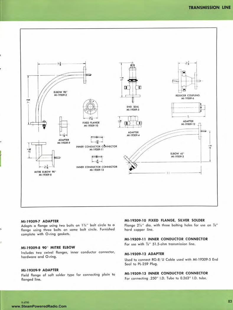
2i MITRE ELBOW 90°
Ml•l9309•B
11 8
ADAPTER Ml•l9309•9
Ml-19309-7 ADAPTER
I FIXED FLANGE
Ml .19309.10
1!1 16
INNER CONDUCTOR C~NNECTOR Ml . J 9309• ll
E31E3 ·
l-1~ INNER CONDUCTOR CONNECTOR
Ml •19309. J3
Adapts a flange using two bolts on l ¾" bolt circle to a flange using three bolts on same bolt circle. Furnished complete with O -ring gaskets.
Ml-19309-8 90° MITRE ELBOW Includes two swivel flanges, inner conductor connector,
hardware and O-ring.
Ml-19309-9 ADAPTER Field flange of soft solder type for connecting plain to
flanged line.
8.6700
=~
TRANSMISSION LINE
END SEAL Ml .19309•5
ADAPTER Ml. 19309.4
REDUCER COUPLING Ml.19309•6
I------ 5 ---~
ADAPTER Ml• 19309.12
Ml-19309-10 FIXED FLANGE, SIL VER SOLDER
Flange 2¼ " die. with three bolting holes for use on 3/a" hard copper line .
Ml-19309-11 INNER CONDUCTOR CONNECTOR
For use with 3/a" 51.5-ohm transmission line.
Ml-19309-12 ADAPTER
Used to connect RG-8/ U Cable used with Ml -19309-5 End Seal to PL-259 Plug.
Ml-19309-13 INNER CONDUCTOR CONNECTOR
For connecting .250" I.D. Tube to 0.263" I.D. tube .
83 www.SteamPoweredRadio.Com
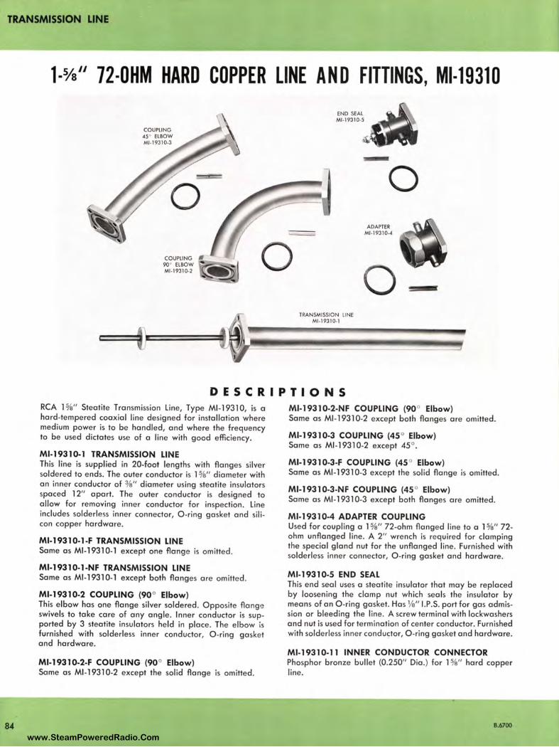
TRANSMISSION LINE
84
1-¾" 72-0HM HARD COPPER LINE AND FITTINGS, Ml-19310
COUPLING 45° ELBOW Ml -19310-3
COUPLING 90° ELBOW 1:"...--.::C--.l Ml -19310-2
END SEAL Ml -19310-5
TRANSMISSION LINE Ml -19310-1
0 ADAPTER
Ml-1931 0-4
DESCRIPTIONS RCA 1%" Steotite Transmission Line, Type Ml-19310, is a hard-tempered coaxial line designed for installation where medium power is to be handled, and where the frequency to be used dictates use of a line with good efficiency.
Ml-19310-1 TRANSMISSION LINE This line is supplied in 20-foot lengths with flanges silver soldered to ends. The outer conductor is l %" diameter with on inner conductor of 3/e" diameter using steotite insulators spaced 12" apart. The outer conductor is designed to allow for removing inner conductor for inspection. Line includes solderless inner connector, O-ring gasket and silicon copper hardware.
Ml-19310-1-F TRANSMISSION LINE Some as Ml-1 931 0-1 except one flange is omitted.
Ml-19310-1-NF TRANSMISSION LINE Some as Ml -1931 0-1 except both flanges ore omitted.
Ml-19310-2 COUPLING (90° Elbow) This elbow hos one flange silver soldered. Opposite flange swivels to toke co re of any angle. Inner conductor is supported by 3 steatite insu lators held in place. The elbow is furnished with solderless inner conductor, O-ring gasket and hardware.
Ml-19310-2-F COUPLING (90° Elbow) Some as Ml-1 931 0-2 except the solid flange is omitted.
M l-193 10-2-NF COUPLING (90° Elbow) Some as Ml -19310-2 except both flanges ore omitted.
M l-19310-3 COUPLING (45 ° Elbow) Some as Ml -19310-2 except 45 °.
Ml-19310-3-F COUPLING (45 ° Elbow) Some as Ml-19310-3 except the solid flange is omitted.
Ml-193 10-3-NF COUPLING (45 ° Elbow) Some as Ml-19310-3 except both flanges ore omitted.
M l-193 10-4 ADAPTER COUPLING Used for coupling a l %" 72-ohm flanged line to a 1 %" 72-ohm unflonged line. A 2" wrench is required for clomping the special gland nut for the unflonged line . Furnished with solderless inner connector, O-ring gasket and hardware.
Ml-19310-5 END SEAL This end seal uses a steotite insulator that may be replaced by loosening the clamp nut which seals the insulator by means of on O-ring gasket. Has 1/a" 1.P.S. port for gas admission or bleeding the line. A screw terminal with lockwashers and nut is used for termination of center conductor. Furnished with solderless inner conductor, O -ring gasket and hardware.
Ml-19310-11 INNER CONDUCTOR CONNECTOR Phosphor bronze bullet (0.250" Dia .) for l %" hard copper line.
B.6700
www.SteamPoweredRadio.Com
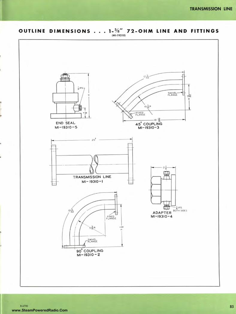
TRANSMISSION LINE
OUTLINE DIMENSIONS •.• 1- 3/s" 72-OHM LINE AND FITTINGS
B.6700
(Ml-19310)
END SEAL Ml-19310-5
i--------- 201
TRANSMISSION LINE Ml-19310-1
90° COUPLING Ml-19310-2
FIXED FLANGE
SWIVEL FLANGE
1--------10 ~-------,
45° COUPLING Ml -19310-3
61.PS.
ADAPTER BOTH SIDES
Ml-19310-4
85 www.SteamPoweredRadio.Com

TRANSMISSION LINE
86
1-1/s" 51.5-0HM HARD COPPER LINE AND FITTINGS, Ml-19112
0 O-RING GASl(fT
Ml-19112-10
OB
RE0UCU (UNGASSf0) Ml-19112•7
ADAPTER (UNGASSE0) Ml,19112-1 6
90" SWl:EP ELBOW • Ml-19112,2 0
REDUCER (GASSf0 3Vo-ll\) © Ml-19113-C-6
iNNER ECTOR STRAIGHT COUPLING (UNGASSED)
Ml-19112-8
Ml-19112,11
UN£ GASSING ACctssORIES Ml-1911.2 ·12
TWANSMISSION UNE Ml-19112-1
DESCRIPTION RCA H 's" Steotite Transmission Line, Type Ml -19112, is a hard-tempered copper line with a nominal impedance of 51 .5 ohms. Because of its low impedance <:Jnd good efficiency at VHF frequencies, this type line is widely used in TV as well as AM and FM installations.
Ml-19112-1 TRANSMISSION LINE This line is supplied in 20-foot lengthst with flanges silversoldered to ends. The outer conductor is 15/e" diameter with on inner conductor of %" diameter using special low loss insulators spaced 12" apart. The outer conductor is designed to allow for removing inne r conductor for inspection. Maximum power roting is 10 kw a t 100 me. Line includes solderless inner connector, O -ring gasket, and silicon copper hardware.
Ml-191 12-1-F TRANSMISSION LINE Some cs Ml -19112-1 exce pt one flange is omitted.
Ml-19112-1-NF TRANSMISSION LINE Some as Ml -19112-1 except both flanges ore omitted .
*Ml-19112-2 COUPLING, 90° ELBOW Elbow with one fixed flange and opposite flange that swivels to toke core of any angle . Inner conductor is supported by insulators spaced 12" apart. There is also a support for the inne r conductor in the center of the
t May be ordered in le n~ths less than 20 feet. When line is to be used for te levision , it should be in multiples of feet. If le ngth is not in mult iples of feet, it is necessary to make up th e d iffe rence by using .647 diamete r conductor Ml -19112-9. When o rdering specify th e Ml number and length required .
elbow. Furnished with inner connector, O -ring gasket and silicon copper hardware.
*Ml-19112-2-F COUPLING, 90° ELBOW Some as Ml -19112-2 except the fixed flange is omitted.
* Ml-19112-2-NF COUPLING, 90° ELBOW Some as Ml -19112-2 except both flanges ore omitted.
*Ml-19112-3 COUPLING, 45 ° ELBOW Some as Ml-1 9 112-2 except 45° .
*Ml-19112-3-F COUPLING, 45 ° ELBOW Some as Ml -19112-3 except the fixed flange is omitted.
*Ml-19112-3-NF COUPLING, 45 ° ELBOW Some as Ml -19112-3 except both flanges ore omitted.
Ml-19112-4 ADAPTER, FOR GASSED LINE Used for adopting a flange type line to on unflonged line. Tools needed ore wrenches for the flange hardware and screwdriver for tightening clamp. Furnished with inner connector, O -ring gasket and hardware.
Ml-19112-5 GAS STOP To be inserted between two flanged sections of line to seal a gassed section from on ungassed section of line.
* Ml-19112-6 REDUCER COUPLING Flanqed coupling used for reducing from 31/e" 51.5-ohm to l %" 51 .5-ohm qassed line. Complete with inner conductor and connectors, O -ring gaskets and hardware.
* Supplied as replacement port only. Do not orde r for new installation s.
B.6700 www.SteamPoweredRadio.Com
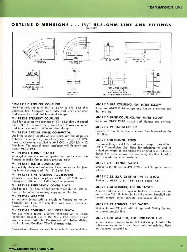
TRANSMISSION LINE
OUTLINE DIMENSIONS •.. 1%" 51.5-OHM LINE AND FITTINGS (Ml-19112)
I-----~~ ---4!,. COUPLING Ml-19112 - 3
COUPLING (UNGASSED) Ml-19112 - 8
* Ml-19112-7 REDUCER COUPLING
90 COUPLING Ml - 19112 -2
GAS STOP M l-19112-5
Used for reducing from 31/e" 51 .5-ohm to l %" 51.5-ohm ungassed line . Complete with outer and inner conductor and connectors and stainless steel clamps.
Ml-19112-8 STRAIGHT COUPLING Used for coupling two sections of l %" 51 .5-ohm unflanged lines. (Not to be used for gassed line .) Consists of outer and inner connectors, stainless steel clamps.
Ml-19112-9 SPECIAL INNER CONDUCTOR Used for splicing lengths of line which are cut at points between the supporting insulators (these are spaced 12"). Inner conductor as supplied is .645 O.D. x .569 1.D. x 12 feet Iona. The special inner conductor will fit inner connector Ml -19112-11.
Ml-19112-10 O-RING GASKET A long-life synthetic rubber gasket for use between the flanges to make flonqe ioints pressure tight.
Ml-19112-11 INNER CONNECTOR A specially desianed soldPrless inner connector for joininq inner conductors of 1 %" 51 .5-ohm line .
Ml-19112-12 LINE GASSING ACCESSORIES Consists of indicators, couplinqs, 25 ft. of ¼" O .D. copp 0 r tubing and flttinas. For indicating line pressure.
Ml-19112-13 EMERGENCY COVER PLATE Used to cap l %" line to keep moisture out during installation, or for other temporary capping of the line.
Ml-19112-16 ADAPTER An adapter (ungassed) to couple a flanqed to c,n u11 -flanqed line . Furnished complete with inner connector, hardware and clamp.
Ml-19112-18 COUPLING, 90° MITRE ELBOW For use where tower structure conflauration or space limitations preve nt use of the Ml-19112-2 swP.ep e lbow - or wherever desirable. Constructed with Teflon dielectric insulators. Excellent VSWR characteristics.
• Supplied as replacement port only. Do not order for new insta llations.
B.6700
1.'t7 1------ ,0·
~ ADAPTER (UNGASSEO)
Ml -19112 -16 TRAN SMISSION LINE
Ml -19112-1
90° MITRe ELBOW Ml •19112·18
45• MITRE ELBOW M1 · 19112 · 21 AISo Avoiloble
ADAPTER (GASSED) Ml-19112 - 4
Ml-19112-18-F COUPLING, 90° MITRE ELBOW Same as Ml -19112-18 exce pt one flange is omitted (on the long leg).
Ml-19112-18-NF COUPLING, 90° MITRE ELBOW Same a s Ml -19112-18 except both flanges are omitted.
Ml-19112-19 HARDWARE KIT Consists of four bolts, four nuts and four lockwashers for 1 %" line.
Ml-19112-20 FLANGE, FIXED The same flange which is used a s an integral part of Ml-19112 Transmission Line. Used for adapting the end of a field -cut-le ngth of line where the original silver-soldered flange has been remove d in shortening the line. Installa tion is made by silver soldering.
Ml-19112-21 FLANGE, SWIVEL Similar to the flange Ml -19112-20 except flang e is free to rotate .
Ml-19112-22, 22-F, 22-NF 45 ° MITRE ELBOW Similar to Ml -19112-18, 18-F, 18-NF except 45° .
Ml-19112-58 REDUCER, 15/a" UNGASSED A cone reducer with a special built-in connector at one and a tyoe " N" 51 .5-ohm jack at the othe r. Supplied with ~pecial integral oute r connector and special clamp.
Ml-19112-59 REDUCER, l5/s" GASSED Similar to Ml-19112-58 with flange and O-ring for use on gassed coaxial line .
Ml-19112-60 ADAPTER, FOR UNGASSED LINE Serves similar purpose to Ml -19112-4 except installed by soft solderinq. Made in one piece- bolts not included. Used on ungassed coaxial line .
87 www.SteamPoweredRadio.Com
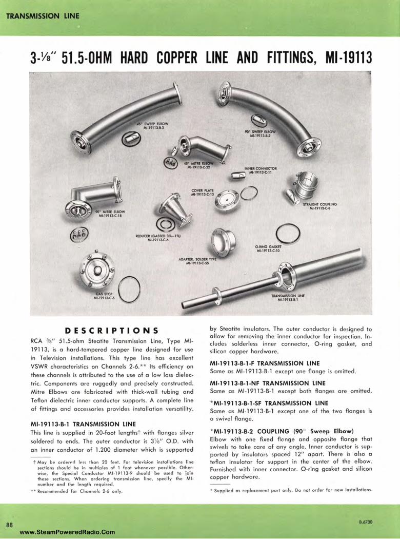
TRANSMISSION LINE
88
3-Ys" 51.5-0HM HARD COPPER LINE AND FITTINGS, Ml-19113
INNER CONNECTOR Ml-19113·C-11
COVER PIATE Ml-19113-C-13
REDUCER (GASSED 3¾-11') Ml-19113-C-6
ADAPTER. SOlDER Ml-19113-C-SS
DESCRIPTIONS RCA 3/s" 51.5-ohm Steatite Transmission Line, Type Ml -
19113, is a hard-tempered copper line designed for use
in Television installations. This type line has excellent
VSWR characte ristics on Channels 2-6. ** Its efficiency on
these channe ls is attributed to the use of a low loss dielec
tric. Components are ruggedly and precisely constructed.
Mitre Elbows are fabricated with thick-wall tubing and
Teflon dielectric inner conductor supports. A complete line
of fittings and accessories provides installation ve rsatility.
Ml-19113-8-1 TRANSMISSION LINE This line is supplied in 20-foot lengthst with flanges silver
soldered to ends. The outer conductor is 31/e" O.D. with
an inner conductor of 1.200 diameter which is supported
t May be arderPd less than 20 feet . Far television install ation s line sections should be in multiples of l foot whenever possible . Otherwise, th e Special Conductor Ml-19113-9 should be used lo 1oon these sections. When ordering transmission line , specify the Ml number and the length required .
** Recommended for Channels 2-6 only.
0 0 -RJNG GASKET Ml-19113-C-10
by Steatite insulators. The outer conductor is designed to allow for removing the inner conductor for inspection. In cludes solderless inner connector, O -ring gasket, and silicon copper hardware .
Ml-19113-8-1 -F TRANSMISSION LINE Same as Ml-19113-B-1 except one flange is omitted.
Ml-19113-8-1-NF TRANSMISSION LINE Same as Ml-19113-B- l except both flanges are omitted.
*Ml-19113-8-1-SF TRANSMISSION LINE Same as Ml-19113-B-l except one of the two flanges is a swivel flange.
*Ml-19113-8-2 COUPLING (90° Sweep Elbow) Elbow with one fixed flcmge and opposite flange that swivels to take care of any angle. Inner conductor is supported by insulators spaced 12" apart. There is also a teflon insulator for support in the center of the elbow. Furnished with inner connector. O-ring gasket and silicon copper hardware.
* Supplied as replacement part only. Do not order for new insta llations.
B.6700
www.SteamPoweredRadio.Com
wigfi
Stolen 2 Line Transparent
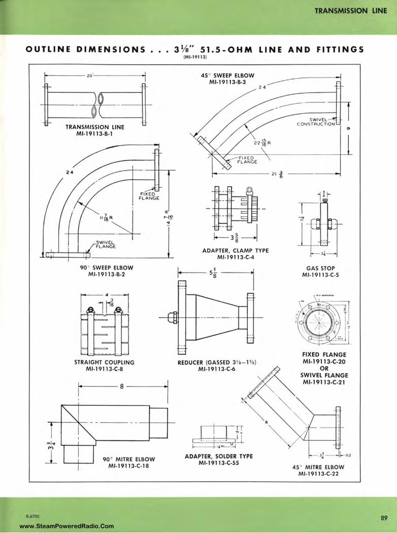
TRANSMISSION LINE
OUTLINE DIMENSIONS .•. 3¼" 51.5-OHM LINE AND FITTINGS
8.6700
(Ml-19113)
- ----20·------ 45 ° SWEEP ELBOW Ml-19113-B-3
ml,r
l
TRANSMISSION LINE Ml-19113-B-1
FIXED FLANGE __ "~~
SWIVEL FLANGE
90" SWEEP ELBOW Ml-19113-B-2
a:
24
ADAPTER, CLAMP TYPE Ml-19113-C-4
STRAIGHT COUPLING REDUCER (GASSED 3 1/s-15/e} Ml-19113-C-8 Ml-19113-C-6
90 ° MITRE ELBOW Ml-19113-C-18
ADAPTER, SOLDER TYPE Ml-19113-C-55
SWIVEL CONSTRUCTION
GAS STOP Ml-19113-C-5
FIXED FLANGE Ml-19113-C-20
OR SWIVEL FLANGE Ml-19113-C-21
3~ 4 l-112
45 ° MITRE ELBOW Ml-19113-C-22
89 www.SteamPoweredRadio.Com
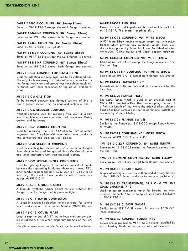
TRANSMISSION LINE
90
* Ml 19113-B-2-F COUPLING (90° Sweep Elbow) Same as Ml -19113-B-2 except the solid flange is omitted .
* Ml-19113-B-2-NF COUPLING (90° Sweep Elbow) Same as Ml -19113-B-2 except both flanges are omitted.
*Ml-19113-B-3 COUPLING (45 ° Sweep Elbow) Same a s Ml -19113-B-2 exce pt 45° .
*Ml-19113-B-3-F COUPLING (45° Sweep Elbow) Same as Ml -19113-B-3 exce pt the solid flange is omitted.
*Ml-19113-B-3-NF COUPLING (45 ° Sweep Elbow) Same as Ml -19113-B-3 exce pt both flanges are omitted.
Ml-19113-C-4 ADAPTER, FOR GASSED LINE Used for adapting a flange type line to an unflanged line. The only tools necessary for installation are wrenches for the flange hardware and screwdriver for tightening clamp. Furnished with inner connector, O-ring gasket and hardware.
Ml-19113-C-5 GAS STOP To be inserted betwee n two flanged sections of line to seal a gassed section from an ungassed section of line.
Ml-19113-C-6 REDUCER COUPLING Flanged coupling used for reducing from 31/a" 51.5-ohm line . Complete with inner conductor and connectors. O-ring gaskets and hardware.
Ml-19113-C-7 REDUCER COUPLING Used for reducing from 31/e" 51.5-ohm to 1%" 51.5-ohm ungassed line. Complete with outer and inner conductor and connectors and stainless steel clamps.
Ml-19113-C-8 STRAIGHT COUPLING Used for coupling two sections of 31/a" 51 .5-ohm unflanged lines. (Not to be used for gassed line.) Consists of outer and inner connectors with stainless steel clamps.
Ml-19113-C-9 SPECIAL INNER CONDUCTOR Used for splicing lengths of line which are cut at points between the supporting insulators (these are spaced 12"). Inner conductor as supplied is 1.282 O .D. x l.136 I.D. x 12 feet long. The special inner conductor will fit inner connector Ml-19113-C- l l.
Ml-19113-C-10 O-RING GASKET A long-life synthetic rubber gasket for use between the flanges to make flanged joints pressure tight.
Ml-19113-C-11 INNER CONNECTOR A specially designed solderless inner connector for joining inner conductors of 31/a" 51 .5-ohm Steatite (Ml -19113) line.
Ml-19113-C-13 COVER PLATE Used to cap the end of 31/a" line to keep moisture out during installation, or for other temporary capping of the line.
• Suppl ied a s rep laceme nt pa rt only. Do not order fo r new installations.
Ml-19113-C-17 END SEAL Except for size and impedance this end seal is similar to Ml -19112-17. The overall length is 4½".
Ml-19113-C-18 COUPLING, 90° MITRE ELBOW A 90° Mitre Elbow having unequal-length legs with swivel flanges which provide any rotational angle. Inner conductor is supported by Teflon insulators. Furnished with two connectors, O-ring gasket and si licon copper hardware.
Ml-19113-C-18-F COUPLING, 90° MITRE ELBOW Same as Ml -19113-C-l 8 except the flange is omitted from the short leg.
Ml-19113-C-18-NF COUPLING, 90° MITRE ELBOW Same as Ml -19113-C-l 8 except both flanges are omitted.
Ml-19113-C-19 HARDWARE KIT Consists of six bolts, six nuts and six lockwashe rs for 31/e inch line.
Ml-19113-C-20 FLANGE, FIXED The same flange which is used as an integral part of Ml-19113 Transmission Line. Used for adapting the end of a field -cut-length of line where the original silver-soldered flange has been removed in shortening the line . Installation is made by silver so ldering.
Ml-19113-C-21 FLANGE, SWIVEL Similar to the flange Ml -1 9113-C-20 except flange is free to rotate.
Ml-19113-C-22 COUPLING, 45 ° MITRE ELBOW Same as Ml -19113-C-l 8 except 45° .
*Ml-19113-C-22-F COUPLING, 45 ° MITRE ELBOW Same as Ml -19113-C-22 except the flange is omitted from the short leg .
*Ml-19113-C-22-NF COUPLING, 45 ° MITRE_ ELBOW Same as Ml -19113-C-22 except both flanges are omitted.
Ml-19113-C-51 CUT-OFF GAUGE A specially-designed tool for cutting and dressing the end of the 1.282 O .D. inner conductor to insure a precision cut.
Ml-19313-8-53 TRANSFORMER, 51 .5 OHM TO 50.5 OHM, CHANNEL 7-13 Used for correct impedance match for Steatite line when used on Channels 7 to 13. Supplied with same hardware as Ml -1 9113-B-l.
Ml-19113-C-54 CUT-OFF GAUGE Similar to Ml -19113-C-51 except for use on 1.200 O .D. inner conductor.
Ml-19113-C-55 ADAPTER, SOLDER-TYPE Serves similar purpose to Ml -19113-C-4 except installed by soft soldering. Made in one piece- bolts not included.
8.6700
www.SteamPoweredRadio.Com
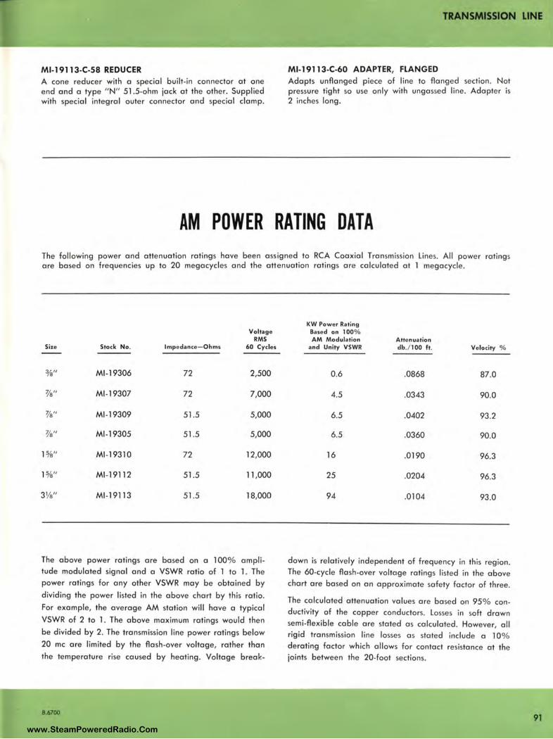
TRANSMISSION LINE
Ml-19113-C-58 REDUCER A cone reducer with a special built-in connector at one end and a type " N" 51 .5-ohm jack at the other. Supplied with special integral outer connector and special clamp.
Ml-19113-C-60 ADAPTER, FLANGED Adapts unflanged piece of line to flanged section. Not pressure tight so use only with ungassed line. Adapter is 2 inches long.
AM POWER RATING DATA The following power and attenuation ratings have been assigned to RCA Coaxial Transmission Lines. All power ratings are based on frequencies up to 20 megacycles and the attenuation ratings are calculated at 1 megacycle.
Voltage RMS
Size Stock No. Impedance- Ohms 60 Cycles
3/e" Ml-19306 72 2,500
3/s" Ml -19307 72 7,000
3/s" Ml -19309 51.5 5,000
3/s" Ml -1 9305 51.5 5,000
1%" Ml-19310 72 12,000
1%" Ml -1 9112 51.5 11,000
31/s" Ml-19113 51.5 18,000
The above power ratings are based on a 100% amplitude modulated signal and a VSWR ratio of 1 to 1. The power ratings for any other VSWR may be obtained by
dividing the power listed in the above chart by this ratio.
For example, the average AM station will have a typical
VSWR of 2 to 1. The above maximum ratings would then
be divided by 2. The transmission line power ratings below
20 me are limited by the flash-over voltage, rather than
the temperature rise caused by heating. Voltage break-
8.6700
KW Power Rating Based on 100% AM Modulation Attenuation
and Unity VSWR db./100 ft. Velocity %
0.6 .0868 87.0
4.5 .0343 90.0
6.5 .0402 93.2
6.5 .0360 90.0
16 .0190 96.3
25 .0204 96.3
94 .0104 93.0
down is relatively independent of frequency in this region. The 60-cycle flash-over voltage ratings listed in the above chart are based on an approximate safety factor of three.
The calculated attenuation values are based on 95% conductivity of the copper conductors. Losses in soft drawn semi-flexible cable are stated as calculated. However, all rigid transmission line losses as stated include a 10% derating factor which allows for contact resistance at the joints between the 20-foot sections.
91 www.SteamPoweredRadio.Com
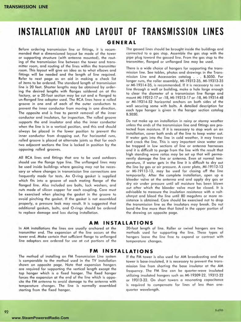
TRANSMISSION LINE
92
INSTALLATION AND LAYOUT OF TRANSMISSION LINES GENERA L
Before ordering transmission line or fittings, it is recommended that a dimensioned layout be made of the tower or supporting structure {with antenna mounted), the routing of the tra nsmission line between the tower and transmitter room, and routing of the lines within the transmitter room. This la yout wi ll give an idea as to what elbows and fittin gs will be needed and the length of line required . Refer to next page as an aid in making a check list of items to be ordered. The standard length of transmission line is 20 feet. Shorter lengths may be obtained by ordering the desired lengths with flanges soldered on at the factory, or a 20-foot section may be cut and a flanged to un-flanged line adapter used. The RCA lines have a rolled groove in one end of each of the outer conductors to prevent the inner conductor from moving in one direction . The opposite end is free to permit removal of the inner conductor and insulators, for inspection. The rolled groove supports the end insulator and also the inner conductor when the line is in a vertical position, and this end should always be placed in the lower position to preve nt the inner conductor from dropping out. For horizontal runs, rolled groove is placed at alternate joints so that for each two adjacent sections the line is locked in position by the opposing rolled grooves.
All RCA lines and fittings that are to be used outdoors should use the flange type line. The unflanged lines may be used inside build ings where gassing may not be necessary or where changes in transmission line connections are frequently made for tests. An O-ring gasket is supplied which fits into a groove of each mating flange of the flanged line . Also included are bolts, lock washers, and nuts made of silicon copper for each coupling. Care must be exercised when placing the gasket in the groove to avoid pinching the gasket. If the gasket is not assembled properly, a pressure leak may result. It is suggested that additional gaskets, bolts, and O -rings should be ordered to replace damage and loss during installation.
The gassed lines should be brought inside the buildings and connected to a gas stop. Assemble the gas stop with the pipe plug toward the gassed line. From the gas stop to the transmitter, flanged or unflanged line may be used.
There is a wide choice of hangers for supporting the transmission line. See tables, photos and drawings in the Transmission Line and Accessories catalog . . . B.5050. For longer runs, the roller assembly, Ml -19312-35, Ml -19313-35 or Ml -1 9314-35, is recommended. If it is necessary to run a line through a wall or building, make a hole large enough to clear the diameter of a transmission line flange and mount Ml -19312-17 or -18, Ml -19313-17 or -18, Ml -19314-48 or Ml -19314-52 horizontal anchors on both sides of the wall securing same with bolts. A detailed description for each type hanger is given in the hanger section catalog B.5050.
Do not make up an installation in rainy or stormy weather unless the ends of the transmission line and fittings are protected from moisture. If it is necessary to stop work on an installation, cover both ends of the line to keep water out. If water gets into the line in cold weather, it may freeze and crack the line. This is very important since water can be trapped in low sections of line or antenna harnesses and it is difficult to purge from the line with the result that high standing wave ratios may be set up that will permanently damage the line or antenna. Even at normal temperature, if water gets in the line it is difficult to dry out the line by gas or air pressure. A cover plate, Ml -19112-13 or Ml -19 113-13, may be used for closing off the line temporarily. After the complete installation, open up a bleeder valve at the antenna end and apply dry gas or dry air under pressure until all moisture has been blown out after which the bleeder valve must be closed. It is advisable to measure the insulation resistance with a voltohmyst and bleed the line until 80 megohms or more resistance is obtained. Care should be exercised not to drop the transmission line as the insulators may break. Do not bend the line more than that listed in the upper portion of the drawing on opposite page.
AM INSTALLATIONS In AM installations the lines are usually anchored at the transmitter end. The expansion of the line occurs at the tower end. Make certain that sufficient flang e to unflanged line adaptors are ordered for use at cut portions of the
20-foot length of line. Roller or swivel hangers are two methods used for supporting the line. These types of hangers leave the line free to expa nd or contract with temperature changes.
FM I NSTALLATIONS The method of installing an FM Transmission Line system is comparable to the method used in the TV installation shown on opposite page. Note that expansion hangers are required for supporting the vertical length except the top hanger which is a fixed hanger. The fixed hanger forces the expansion at the end of the line which is opposite the FM antenna to avoid damage to the antenna with tempera ture changes. The line is normally assembled starting from the fixed hanger.
If the FM tower is also used for AM broadcasting and the tower is base-insulated, it is necessary to prevent the transmission line from shorting the base insulator at the AM frequency. The FM line can be q uarter-wave insulated utilizing insulated hangers such as Ml -19309-22, 19312-22 or 19313-22. On short towers a resonating capacitance is required to compensate for lines of less than onequarter wavelength.
8.6700
www.SteamPoweredRadio.Com
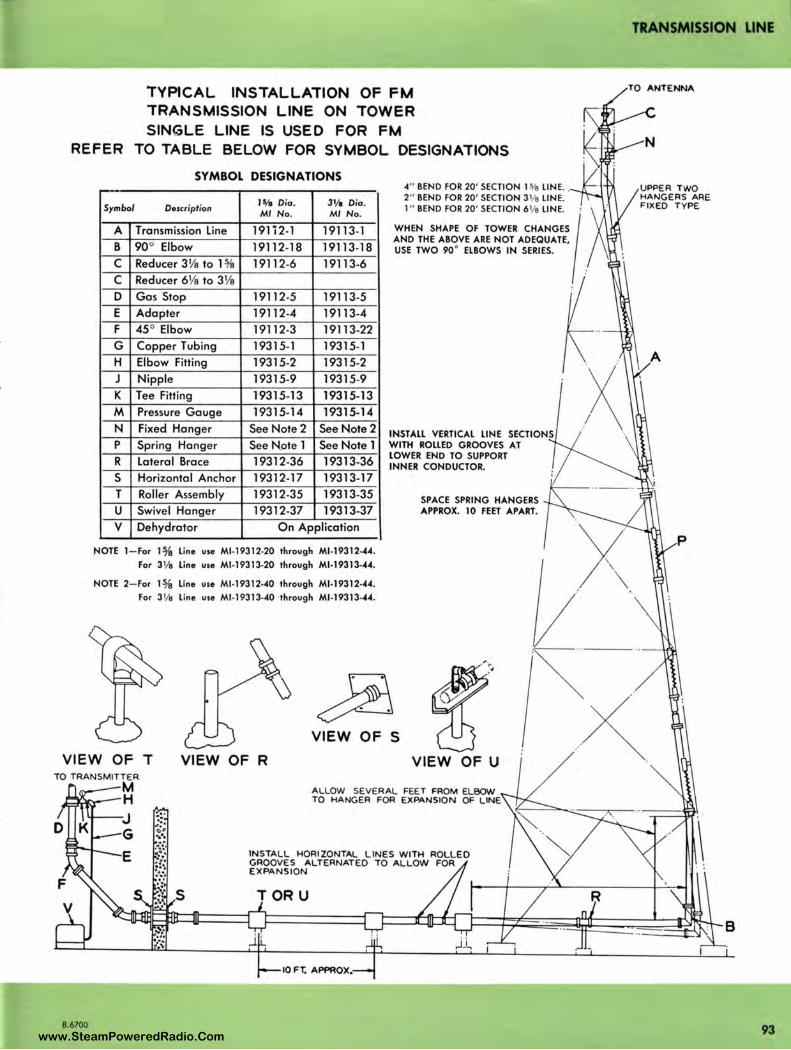
TRANSMISSION LINE
TYPICAL INSTALLATION OF FM TRANSMISSION LINE ON TOWER SINGLE LINE IS USED FOR FM
REFER TO TABLE BELOW FOR SYMBOL DESIGNATIONS
SYMBOL DESIGNATIONS
Symbol Description I 1/a Dio. 31/1 Dia. Ml No. Ml No.
A Transmission Line l9li2-l 19113-l B 90° Elbow 19112-18 19113-18 C Reducer 31/a to l % 19112-6 19113-6 C Reducer 61/a to 31/a D Gas Stop 19112-5 19113-5 E Adapter 19112-4 19113-4 F 45° Elbow 19112-3 19113-22 G Copper Tubing 19315-1 19315-l H Elbow Fitting 19315-2 19315-2 J Nipple 19315-9 19315-9 K Tee Fitting 19315-13 19315-13 M Pressure Gauge 19315-14 19315-14
N Fixed Hanger See Note 2 See Note 2 p Spring Hanger See N.ote l See Note l R Lateral Brace 19312-36 19313-36 s Horizontal Anchor 19312-17 19313-17 T Roller Assembly 19312-35 19313-35
u Swivel Hanger 19312-37 19313-37 V Dehydrator On Application
.NOTE 1-For 1% line use Ml-19312-20 through Ml-19312-44.
For 3 1/e line use Ml-19313-20 through Ml-19313·"""·
NOTE 2- For 1¾ line use Ml -1 9312-40 through Ml-19312-44.
For 31/e l ine use Ml-19313-40 ·through Ml-19313-44.
4" BEND FOR 20' SECTION 15,1a LINE . . 2" BEND FOR 20' SECTION 31/e LINE. 1" BEND FOR 20' SECTION 61/e LINE.
WHEN SHAPE OF TOWER CHANGES I AND THE ABOVE ARE NOT ADEQUATE, USE TWO 90 ° ELBOWS IN SERIES.
INSTALL VERTICAL LINE SECTIONS WITH ROLLED GROOVES AT LOWER END TO SUPPORT INNER CONDUCTOR.
SPACE SPRING HANGERS APPROX. 10 FEET APART.
'~ .. ··
VIEW OF S
VIEW OF T VIEW OF R VIEW OF U ><"
B.6700
INSTALL HORIZONTAL LINES WITH ROLLED GROOVES ALTERNATED TO ALLOW FOR EXPANSION
TORU
~~~~~f---i'1u>:ni--~m-_-_-_---l--r-?===--=--=--=--=--=...i-r71---~r.--l-r J===t-~~~~==~~~~ j '
10 FT. APPROX.
93 www.SteamPoweredRadio.Com
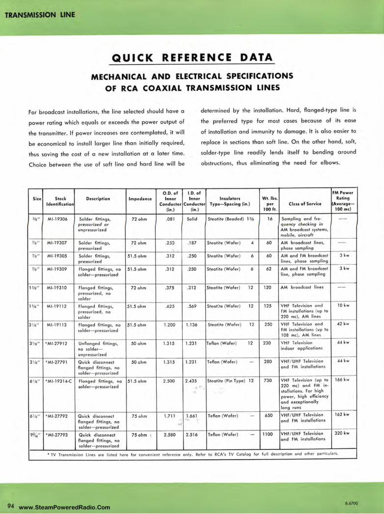
TRANSMISSION LINE
94
QUICK REFERENCE DATA
MECHANICAL AND ELECTRICAL SPECIFICATIONS
OF RCA COAXIAL TRANSMISSION LINES
For broadcast installations, the line selected should have a
power rating which equals or exceeds the power output of
the transmitter. If power increases are contemplated, it will
be economical to install larger line than initially required,
thus saving the cost of a new installation at a later time.
Choice between the use of soft line and hard line will be
O.D. of Size Stock Description Impedance Inner
I.D. of Inner
determined by the installation . Hard, flanged-type line is
the preferred type for most cases because of its ease
of installation and immunity to damage. It is also easier to
replace in sections than soft line. On the other hand, soft,
solder-type line readily lends itself to bending around
obstructions, thus eliminating the need for elbows.
FM Power Insulators Wt. lbs. Rating
Identification Conductor Conductor Type-Spacing (in .) per Clzss of Service {Average-(in .) (i n.) 100 ft. 100 me)
3/a" Ml-19306 Solder fittings, 72 ohm .081 Solid Steotite (Beaded) 1 ¾ 16 Sampling and fre- --pressurized or quency checking in unpressurized AM broadcast systems,
mobile, aircraft
7/e" Ml-19307 Solder fittings , 72 ohm .25:> .187 Steotite (Wafer) 4 60 AM broadcast lines, --pressurized phase somplin!I
'l's'' Ml -19305 Solder fittings, 51 .5 ohm .312 .250 Steotite (Wafer) 6 60 AM and FM broadcast 3kw pressurized lines, phase sampling
7/e" Ml-19309 Flanged fittings, no 51.5 ohm .312 .250 Steotite (Wafer) 6 62 AM and FM broadcast 3 kw solder- pressurized line, phase sampling
1%" Ml-19310 Flanged fittings, 72 ohm .375 .312 Steotite (Wafer) 12 120 AM broadcast lines --pressurized , no solder
1%" Ml -19112 Flanged fitting s, 51.5 ohm .625 .569 Steot:te (Wafer) 12 125 VHF Television and 10 kw
pressurized, no FM installations (up to
solder 220 me), AM lines
3 1/e" Ml -19113 Flanged fittings, no 51.5 ohm 1.200 1.136 Steotite (Wafer) 12 250 VHF Television and 42 kw
solder- pressurized FM installations (up to 108 me), AM lines
3 1/e" *Ml -27912 Unflonged fitting s, 50 ohm 1.315 1.231 Teflon (Wafer) 12 230 VHF Television 44 kw
no solder- indoor applications
unpressurized
3 1/e" *Ml -27791 Quick di sconnect 50 ohm 1.315 1.231 Teflon (Wafer) - 280 VHF/ UHF Television 44 kw
flanged fitt ings, no and FM installations
solder- pressurized
6 1/e" *Ml-19314-C Flanged fitting s, no 51.5 ohm 2.500 2.435 Steotite (Pin Type) 12 730 VHF Te levision (up to 166 kw
solder- pressurized <' 220 me) and FM in• stollotions. For high power, high efficiency and exceptionally long runs
6 1/e" *Ml -27792 Quick disconnect 75 ohm 1.711 1.661 Teflon (Wafer) - 650 VHF/ UHF Tele~ision 162 kw
flanged fittings, no ) .. and· FM installations
solder- pressurized .,
9¾'6" *Ml -27793 Quick disconnect 75 ohm 1 2 .580 2.516 Teflon (Wafer) - 1100 VHF/ UHF Television 320 kw
flanged fittings, no and FM installations
solder- pressurized
• TV Transmission lines are lis ted here for convenient reference onl y. Refer to RCA's TV Catalog for full description and other part icu lars.
B.6700 www.SteamPoweredRadio.Com
wigfi
Stolen 2 Line Transparent

TRANSMISSION LINE
OPEN WIRE LINES
FEATURES
• Simplicity
• Low maintenance cost
• Open for constant inspection
• Requires no auxiliary apparatus (dehydrators, gas, etc.)
• High power handling capacity at low cost
USES The six wire open line is intended for transmission of RF power from the transmitter to the antenna. The six wire line may be used for either phased arrays or non-directional antennas. It is suitable for use at any standard broadcast frequen cy and is designed for use in all weather conditions.
DESCRIPTION O pen wire transmission lines when properly designed and constructed, provide high power handling capabilities at low cost. The open wire line is reliable and may be serviced easi ly. The various open-wire line kits simplify the installation of an efficient line suitable for RF powers up to 150 KW. Radiation is made negligible by using a six wire line consisting of two central power conductors surrounded by four grounded conductors. By use of this line configuration, with appropriate spacing between conductors, a characteristic impedance of 230 ohms is obtained which results in an economy of phasing and terminating equipment.
Buil d ing dead•end termination of open wire line leading to flve towers. lightn ing protector ho rn•gaps are visible above each ground plate.
B.6712
SPECIFICATIONS Number 6 Hard Drawn Copper Wire, for transmission line conductors. Weight 79.4 lbs./1000 ft .
Stock lde ntificotion ........................................................................ Ml•28010
Ml -280 13 Transmission Line pole and cap. 4" diameter steel pole, 20' long with cap to close the upper end. May be drilled at installation for use with either L-13852 Bayonet Insulator, or L-13854 Building Dead End Kit. Stock Identificat ion ............. ......... ... ............. .................................. Ml•28013
Transmission Line Wire Bui lding Dead End Kit for terminating line at building, strain insulators, turnbuckles, grounding strap, line con-nectors. , .,
Stock Identification ....................... ............................. ................ ...... l• l 3853
Pole Dead End Kit, fittings needed to terminate line, strain insulators, turnbuckles, ' line connectors, grounding strap, guy material, guy anchor brackets.
Stock Identification .................. ......................................... ............... L.13854
Lead In Kit, fittings needed to run line through building wall at transmitter or tuning house. Lead in bowl and mounting plate, lightning horn gap, lightning reactor, grounding materials.
Stock Identification ................................................................... ....... L.13855
Transmission Line Bayonet Insulator Bayonet Insulator Assembly for supporting line, to be spaced at 50 feet, with supporting bracket and post insulator " U" bolts.
Stock Identification .......... .................. .................. .... ................ ........ l• 13852
95 www.SteamPoweredRadio.Com
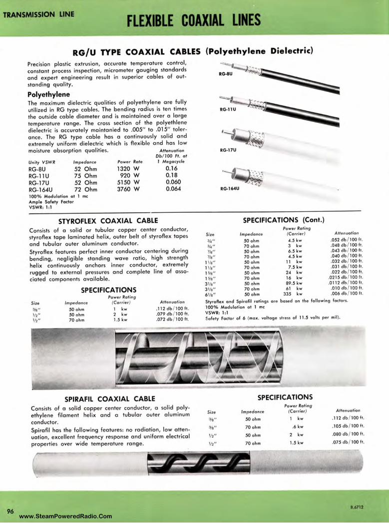
TRANSMISSION LINE FLEXIBLE COAXIAL LINES
96
RG/U TYPE COAXIAL CABLES (Polyethylene Dielectric)
Precision plastic extrusion, accurate temperature control,
constant process inspection, micrometer gauging standards
and expert engineering result in superior cables of out
standing quality.
Polyethylene The maximum dielectric qualities of polyethylene are fully
utilized in RG type cables. The bending radius is ten times
the outside cable diameter and is maintained over a large
temperature range . The cross section of the polyethlene dielectric is accurately maintanied to .005" to .015" toler
ance. The RG type cable has a continuously solid and extremely uniform dielectric which is flexible and has low
moisture absorption qualities. Attenuation
Un ity VSWR Impedance
RG-8U 52 Ohm RG-1 lU 75 Ohm RG-17U 52 Ohm RG-164U 72 Ohm 100% Modulation al 1 me Ample Safety Factor VSWR: 1:1
Power Rate
1320 W 920 W
5150 W 3760 W
Ob/JOO Ft. at I Megacycle
0.16 0.18 0.060 0.064
STYROFLEX COAXIAL CABLE Consists of a solid or tubular copper center conductor, styroflex tape laminated helix, outer belt of styroflex tapes
and tubular outer aluminum conductor.
Styroflex features perfect inner conductor centering during bending, negligible standing wave ratio, high strength
helix continuously anchors inner conductor, extremely
rugged to external pressures and complete line of asso
ciated components available.
SPECIFICATIONS Power Rating
Size Impedance (Carrier) Attenuation
¾" 50 ohm l kw .112 db / 100 ft.
½" 50 ohm 2 kw .079 db / 100 It. ½" 70 ohm 1.5 kw . 072 db / 100 It.
SPIRAFIL COAXIAL CABLE Consists of a solid copper center conductor, a solid poly
ethylene filament helix and a tubular outer aluminum
conductor.
Spirafil has the following features: no radiation, low atten
uation, excellent frequency response and uniform electrical properties over wide temperature range.
SPECIFICATIONS (Cont.) Power Rating
Size Impedance (Carrier} Attenuation
¾" 50 ohm 4.5 kw .052 db / 100 It. ¾" 70ohm 3 kw .048db / 100lt. 7,/9" 50 ohm 6.5 kw .043 db / 100 It. 7/9" 70 ohm 4.5 kw .040 db / 100 It.
l l/9" 50 ohm 11 kw .032 db / 100 It. l l/9" 70ohm 7.5kw .031 db / 100lt. 1%" 50ohm 24 kw .022db / 100lt. 1%" 70ohm 16 kw .0215db / 100ft. 31/9" 50 ohm 89.5 kw .0112 db / 100 It. 3 1/9" 70 ohm 61 kw .010 db / 100 It. 61/e" 50ohm 335 kw .006db / 100lt.
Styroflex and Spirofil ratings ore hosed on the following factors.
100 % Modulation al 1 me VSWR: 1:1 Safety Factor of 6 {max. voltage stress of 11 .5 volts per mil ) .
Size
¾"
3fa"
½"
½"
SPECIFICATIONS Power Rating
Impedance (Carrier}
50 ohm l kw
70 ohm . 6 kw
50 ohm 2 kw
70 ohm 1.5 kw
Attenuation
.112 db / 100 ft .
.105 db / 100 ft .
.080 db / 100 It.
.075 db / 100 ft .
8.6712
www.SteamPoweredRadio.Com

TRANSMISSION LINE
TRANSMISSION LINE ACCESSORIES AM· FM
(Cl.AMP ON ROUNO MEIIIERS)
Ml-19112-41 -15/1 Ml- 19113-41-3¼ Ml- 19112-42- 15/4 Ml-19113-42 -31/1
(MOUNT THROUGH HOLE)
Ml-19112-47-1 ¾ Ml-19113-47-31/,
(MOUNT THROUCH HOLE)
Ml -19112-44-1 ¾ Ml-19113-44-31/1
00
FEATURES
!MOUNT THROUCH HOLE)
Ml-19112-15-11/1 Ml -19113-15-31/,
• Hangers available for any Television transmission line mounting requirements
• Designed for maximum ease of installation
• Materials used for construction resist deterioration from weather
• Sturdy rugged construction assures permanent, reliable installation
• Other accessories such as horizontal roller supports, horizontal anchors, lateral braces, indoor hanger kits, etc., afford a complete "matched" installation
1.6710
00 (MOUNT THROUGH HOLE)
Ml-19112-49-1¾
~ .,_,,,,,~,-3¼
USES
RCA's complete line of AM-FM Transmission Line Hangers
offers maximum flex ibility, efficiency and economy in
meeting modern needs in supporting transmission line runs
whether on the tower or in the horizontal run from trans
mitter to tower. Installation eng ineers have carefully
selected a representative line of fixed and expansion type
hangers including special miscellaneous type accessories
and convenient indoor mounting kits needed for a work
able and versatile transmission system.
Hangers are available for any broadcast transmission line
mounting requirement of either AM or FM broadcast
stations. The hangers are designed for maximum ease of
installation, and all materials used for construction resist
deterioration from weather conditions. Their sturdy, rugged
construction assures permanent, reliable installation.
www.SteamPoweredRadio.Com

TRANSMISSION LINE
DESCRIPTION RCA has a complete line of hangers designed for 3/s",
l %", and 31/s" diameter AM-FM transmission lines. There are hange rs for mounting both single and dual lines either vertically or horizontally to flat members, pipes, or angular
members. These hangers consist of several general types,
i.e., spring suspended ex pansion hangers (which permit differential thermal expansion of the line and tower),
swivel hangers which provide for either horizonal or ver
tical mounting of the line, and lateral braces and direct mounting anchors: Of these there are short hangers for close mounting, long hangers to provide additional clear
ance, and insulated as well as noninsulated types. The
direct mounting type of hanger requires drilling of a hole in the mounting surface, but no drilling is required for the other types.
The instructions supplied with each spring-suspension hanger should be closely followed for proper installation.
The practice is to space the hangers at approximate l 0-
foot intervals. The line section at the tower top is firmly
secured by two fixed hangers, and the lower sections are suspended by spring hangers to allow for differential thermal expansion.
Descriptive information on individual fixed, expansion and miscellaneous type hangers is provided in the following
tables where other pertinent information, including ordering information is set forth . Pictures of each type hanger and outline drawing keyed to the tables should be consulted.
D ESCRIPTIONS AND SPECIFICATIONS FOR FIXED HANGERS
-
ITEM
FIXED HANGERS, CLAMP ON ROUND MEMBERS
For fastening 1 line to round members. Supplied with 1 hose clomp.
SEE OUTLINE DIMENSION " A"
--FIXED HANGERS, MOUNT THROUGH HOLE
For direct mounting of 1 line. Requires mounting hole. Mounting bolt ond hose clamp supplied. Type with B di-mension may be suspended by moving mounting bolt to other hole.
SEE OUTLINE DIMENSION " C"
FIXED HANGER, MOUNT THROUGH HOLE
For direct mounting of two lines. Complete with hose clamps.
SEE OUTLINE DIMENSION " E"
-jB ;::h : I I
Requires mounting hole.
DIMENSIONS (inches)
A
4 - 4¾ 4¾ - 61/a 4¾- 5½ 5 ½ - 63/a
2¾ 5¾ 3 ½ 6½ 5%
3¾ 3¾ 5½ 5 ½
r,il',.8--i ' : I
I
8
1 - 2¼ 2½- 5 1 - 2¼ 2½ - 5
1J{6 -
1½'6 -
1½'6
2-9132 5 3-1132 5
l~r. ' I l_~-, 1 I
I I I I
~ A_i:~
C DIA.)
0 © ( MOUNT THROUGH
, HOLE) (CLAMP ON ROUND MEMBERS) .
I ,J-. •
GROUNDED LINE SIZE RCA OR AND REFERENCE
C INSULATED CAPACITY NO.
grounded 1%(1) Ml-19112-41 grounded 1%(1) Ml-19112-42 grounded 3 1/a (1) Ml-19113-41 grounded 3 1/a (1) Ml-19113-42
3/a grounded 1%(1) Ml-19112-44 3/a grounded 1%(1) Ml-19112-47 ½ grounded 31/a (1) Ml-19113-44 ½ grounded 31/ a (1) Ml-19113-47 o/a grounded 6 1/a (1) Ml-19314-44
½ grounded 1 % (2) Ml-19112-15 ½ insulated 1 o/a (2) Ml-19112-49 ½ grounded 3 1/a (2) Ml-19113-15 ½ insulated 33/a (2) Ml-19113-49
B.6710
www.SteamPoweredRadio.Com

0
8
B.6710
TRANSMISSION · LINE
EXPANSION HANGERS FOR SINGLE LINE
Ml-19112-23-1 % Ml-19113-23-31/e
Ml-19112-26- 1% Ml-19113-26-31/e
( CLAMP ON ROUND MEMBERS)
Ml-19309-25- 3/e
(MOUNT THROUGH HOLE)
Ml-19112-32-1% Ml-19113-32-31/e
0
( MOUNT THROUGH HOLE)
Ml-19309-33- 3/e
Ml-19112-25-1 o/e Ml-19113-25-31/e Ml-19112-28-1% Ml-19113-28-31/e
( CLAMP ON ROUNO MEMBERS)
Ml-19309-26- 3/e
(MOUNT THROUGH HOLE)
Ml-19112-33-1 o/e Ml-19113-33-31/e
0 0 0
( MOUNT THROUGH HOLE)
Ml- 19309-34- 3/e
(CLAMP ON ANGULAR MEMBERS)
Ml-19309-29- 3/e
(CLAMP ON ROUNO MEMBERS)
Ml-19309-23- 3/e
( CLAMP ON ROUNO MEMBERS)
Ml-19309-27- 3/e
(MOUNT THROUGH HOLE)
Ml-1 9112-34-1¾ Ml-19113-34-31/e
(CLAMP ON FLAT MEMBERS)
Ml-19309-20- 3/e .
(CLAMP ON ANGULAR MEMBERS)
Ml-19309-30- 3/e ~
, 1>• 0 •
(CLAMP ON ROUNO MEMBERS)
• ~1-19309-24- 3/e
( CLAMP ON ROUNO MEMBERS)
Ml-19309-28- 3/e
( MOUNT THROUGH HOLE)
Ml-19309-32- 3/e
(CLAMP ON FLAT MEMBERS)
Ml-1 9309-21 - 3/e
(CLAMP ON ANGULAR MEMBERS)
Ml-19309-31 - 3/e
EXPANSION HANGERS FOR DUAL LINES~
0 0
(MOUNT THROUGH HOLE)
Ml-19112-14-.1¾ Ml-19113-14-31/e
0 0
(MOUNT THROUGH HOLE)
Ml-19112-48-1¾ Ml-19113-48-31/e
99 · www.SteamPoweredRadio.Com

TRANSMISSION LINE
DESCRIPTION AND SPECIFICATION FOR EXPANSION HANGERS
DIMENSIONS (i nches) GROU NDED LINE SIZE RCA OR AND REFE RENCE
ITEM A B C INSULATED CAPACITY NO.
4 1/a - 4 7,/a 1 - 2¼ grounded 1%(1) Ml -19112-23
EXPANSION HANGERS, CLAMP ON ROUND MEMBERS 41;a - 6¼ 2½ - 5 grounded 1%( 1) Ml -19112-26 5¾- 6 ½ 1 - 2¼ insulated 1%( 1) Ml -19112-25
Spring-suspended hanger for clamping single line to round 6 ½ - 11K6 2½- 5 insulated 1% (1) Ml -19112-28 member. Complete with hose clamp. Spring must be pre- 4 7/a - 5% 1 - 2¼ g rounded 3 1/a (1) Ml -19113-23 loaded at installat ion . 5%- 7 2½- 5 grounded 3 1/a (1) Ml -19113-26 SEE OUTLINE DIMENSION " A" 6½- 7 ¼ 1 - 2¼ insulated 3 1/a (1) Ml -19113-25
7 ¼ • 81.!-{6 2½ -5 in sulated 3 1/a (1) Ml -19113-28
-- --
EXPANSION HANGERS, CLAMP ON ROUND MEMBERS 3K6 1 - 2 ¼ grounded 7/a (1) Ml -19309-23
Same uses as above hanger " A" but also have pivot bolt to 61K6 1 - 2¼ grounded 7/a (1) Ml -19309-24
compensate for line misalignment. Complete with hose clamp. 61K6 1 - 2¼ insulated 7/a (1) Ml -19309-25
Spring must be preloaded al installation. 31/a 2¼ - 5 grounded 1/a (1) Ml -19309-26
SEE OUTLINE DIMENSION " B" 7 2¼ - 5 grounded 7,/a (1) Ml -19309-27
7 2¼ - 5 insulate d 7,/a (1) Ml -19309-28
EXPANSION HANGERS, MOUNT THROUGH HOLE 2 7,/a 1" max. 3/s grounded 1%( 1) Ml -19112-32
51/a 1" max . 3/s g rounded 1%(1) Ml -19112-33 Spring-suspended hanger for mounting through single hole . 5¼ 1" max . 3/s insu lated 1%( 1) Ml -19112-34 Complete with hose clamp. Spring must be preloaded al 3 % 1" max. ½ grounded 3 1/ a (1) Ml -19113-32 installation. 6% 4" max . ½ g rounded 3 1/a (1) Ml -19113-33 SEE OUTLINE DIMENSION " C" 6 1" max . ½ insula ted 3 1/a (1) Ml -19113-34
EXPANSION HANGERS, MOUNT THROUGH HOLE 31}(6 g rounded 7/a (1) Ml -19309-32
Spring-suspended for mounting through single hole. Similar 1K6 g rounded 7/a (1) Ml -19309-33
to preceding type " C" but has pivot bolt lo compensate for 71(6 insulated 1/a (1) Ml 19309-34
line misal ignment. Spring must be preloaded al installation . SEE OUTLINE DIMENSION " D"
·-EXPANSION HANGERS, MOUNT THROUGH HOLE 3 ¾ 2-5 / 32 ½ g rounded 1%(2) Ml -19112-14
For spring-suspension of two lines. Requires mounting hole . 3 ¾ 5 ½ insulated 1%(2) Ml -19112-48
Complete with hose clamps. Spring preloaded al installation . 5½ 3 1/a ½ g rounded 3 1;a (2) Ml -19113-14
SEE OUTLINE DIMENSION " E" 5½ 5 ½ insulated 3 1/a (2) Ml -19113-48
EXPANSION HANGERS, CLAMP ON FLAT MEMBERS 4 g rounded 7/a (1) Ml -19309-20
Spring-suspended hanger for fostening 1 line to flat mem- 7% grounded 1/a (1) Ml-19309-21
bers. Uses adjustable vise-like clamp. Pivot bolt compensates l o/a in sulated 1/a (1) Ml -19309-22
for line misalignment. Complete with hose clamp. Spring must be preloaded at installation. SEE OUTLINE DIMENSION " F"
EXPANSION HANGERS, CLAMP ON ANGLES 4¾'6 7" max. g rounded 1/a (1) Ml -19309-29
Spring-suspended hanger for clamping 1 line to structural 71¾'6 7" max . grounded 1/a (1) Ml -19309-30
angles. Pivot bolt compensates for line misalignment. Com- 7 1¾'6 7" max . insulated 7/a (1 ) Ml-19309-31
plete with hose clamp. Spring must be preloaded at installa-tion . SEE OUTLINE DIMENSION "G"
EXTENSION KIT 4½ 7 ½ ½ Ml -19113-16
Extends th e mounting of grounded dual hangers lo align with insulated dual hangers. SEE OUTLINE DIMENSION " H"
CLAMP KITS (FOR ROUND MEMBERS) 3 ¼ 1 - 2¼ Ml -1911 3-56
Adapts any d irect-mounting (mount through hole ) type of 5¾ 2½- 5 Ml -19113-57
Ml -19113 hanger to round members. SEE OUTLINE DIMENSION "J"
CLAMP KITS (FOR ANGULAR MEMBERS) 4 • 8 Ml 1911 3-59 Adapts any direct-mounting (mount through hole ) type of Ml -19113 hanger to angular members. SEE OUTLINE DIMENSION " K"
100 8.6710 www.SteamPoweredRadio.Com
wigfi
Stolen 2 Line Transparent
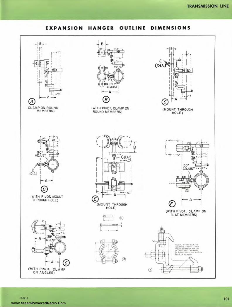
TRANSMISSION LINE
EXPANSION HANGER OUTLINE DIMENSIONS
--j 8 f-r -r.1 I I I
I' I
I 1 1 I I I I
I : I : I I I
I
I
'- - -;~
0 A
(CLAMP ON ROUND MEMBERS)
8.6710
. I
~A-i ®
(WITH PIVOT, MOUNT THROUGH HOLE)
~A~ © lWITH PIVOT. CL AMP
ON ANGLES)
® (WITH PIVOT. CLAMP ON ROUND MEMBERS)
--~,.. -/ I '-
I .- +i-\ ' I , - - B
r- ~ .L -~ I~ 1 ,. a .
1 f ~ • ., I . .
I C · , ' I
1~1: t•! ·~f+J
© (MOUNT THROUGH
HOLE)
t.J ® -8-·- --3+FEfjjjj- -
- •-
@
®
(MOUNT THROUGH HOLE)
® (WITH PIVOT, CLAMP ON
FLAT MEMBERS)
RE.M()\,11,L Of 1Hl5 SOL T ANO
INSERTION Al POINl0
'i'W1LL PROVIDE EXTENSION FOR USE ON LAAGEA FLAT MEMBERS., 0A ACROSS LEGS Of A LAAC.EA ANc.uLAR MEMBE
101 www.SteamPoweredRadio.Com
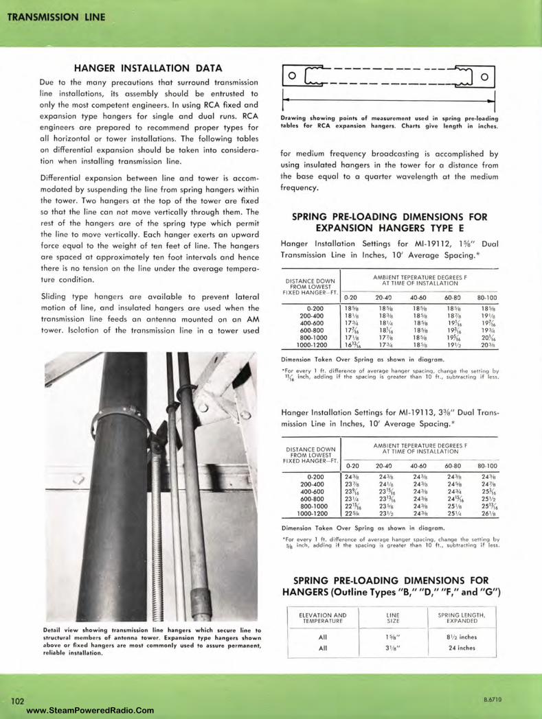
TRANSMISSION LINE
102
HANGER INSTALLATION DATA Due to the many precautions that surround transmission
line installations, its assembly should be entrusted to
only the most competent engineers. In using RCA fixed and
expansion type hangers for single and dual runs. RCA
engineers are prepared to recommend proper types for
all horizontal or tower installations. The following tables
on differential expansion should be taken into considera
tion when installing transmission line.
Differential expansion between line and tower is accom
modated by suspending the line from spring hangers within
the tower. Two hangers at the top of the tower are fixed
so that the line can not move vertically through them. The
rest of the hangers are of the spring type which permit
the line to move vertically. Each hanger exerts an upward
force equal to the weight of ten feet of line . The hangers
are spaced at approximately ten foot intervals and hence
there is no tension on the line under the average tempera
ture condition.
Sliding type hange rs are available to prevent lateral
motion of line, and insulated hangers are used when the
transmission line fee ds an antenna mounted on an AM
tower. Isolation of the transmission line in a tower used
Detail view showing tran,mission line hangers which secure line to structura l members of antenna tower. Expansion type ha ngers shown above or fixed hangers are most commonly used to assure permanent, re liable installation.
I c------------:J I 0 ----- - --- ---- 0
Drawing sho wing p o ints of measurement used in spring pre-loading tables for RCA expansion hangers. Charts give length in inches.
for medium frequency broadcasting is accomplished by
using insu lated hangers in the tower for a distance from
the base equal to a quarter wavelength at the medium
freq uency.
SPRING PRE-LOADING DIMENSIONS FOR EXPANSION HANGERS TYPE E
Hanger Installation Settings for Ml-19112, l %" Dual
Transmission Line in Inches, l O' Average Spacing. *
DISTAN CE DOWN AMBI ENT TEPERATURE DEGREES F
FROM LOWEST AT TIME OF INSTALLATION
FIXED HANGER- FT. 0-20 20-40 40-60 60-80 80-100
0-200 18% 18% 185/a 18% 18 5/a 200-400 18 1/a 183/e 185/a 187/e 19 1/a 400-600 17¾ 18¼ 18 5/a 19}{6 19K, 600-800 li!,(6 18}{6 18 5/a 193{6 19¾ 800-1000 17 1/a 17 3/e 18 5/a 19~ 6 20J{,
1000-1200 161K. 17¾ 18 5/a 19½ 203/a
Dimension Token Over Spring a s shown in diagrom.
• For every 1 ft. difference of average hanger spacing, change the selling by 1}{6 inch , adding if the spacing is grea ter than 10 ft ., subtracting if less.
Hanger Installation Settings for Ml-19113 , 33/a" Dual Trans
mission Line in Inches, 10' Average Spacing.*
DISTAN CE DOWN AMBIENT TEPERATURE DEGREES F
FROM LOWEST AT TIME OF INSTALLATION
FI XED HANGER- FT. 0-20 20-40 40-60 60-80 80-100
0-200 243/a 243/e 24 3/e 243/a 243/e 200-400 23 7/e 24 1/e 243/a 24 5/e 24 7/a 400-600 23~ 6 23 % 243/e 24¾ 253{6 600-800 23 ¼ 2313{6 243/a 241~ 6 25 ½ 800-1000 221~, 23 1/s 243/a 25 1/e 2513,',
1000-1200 221/A 23½ 243/a 25 ¼ 261/e
Dimension Taken Over Spring as shown in diagram.
"' For every 1 ft. difference of average hanger spacing , change the setting by % inch, add ing if the spacing is grea ter tha n 10 f t. , subtracting if less .
SPRING PRE-LOADING DIMENSIONS FOR HANGERS (Outline Types "B," "D," "F," and "G")
ELEVATION AND TEMPERATURE
All
All
LIN E SIZE
15/a"
31/a"
SPRI NG LENGTH, j EXPANDED
- --- ---- -8½ inches
24 inches
8.6710
www.SteamPoweredRadio.Com
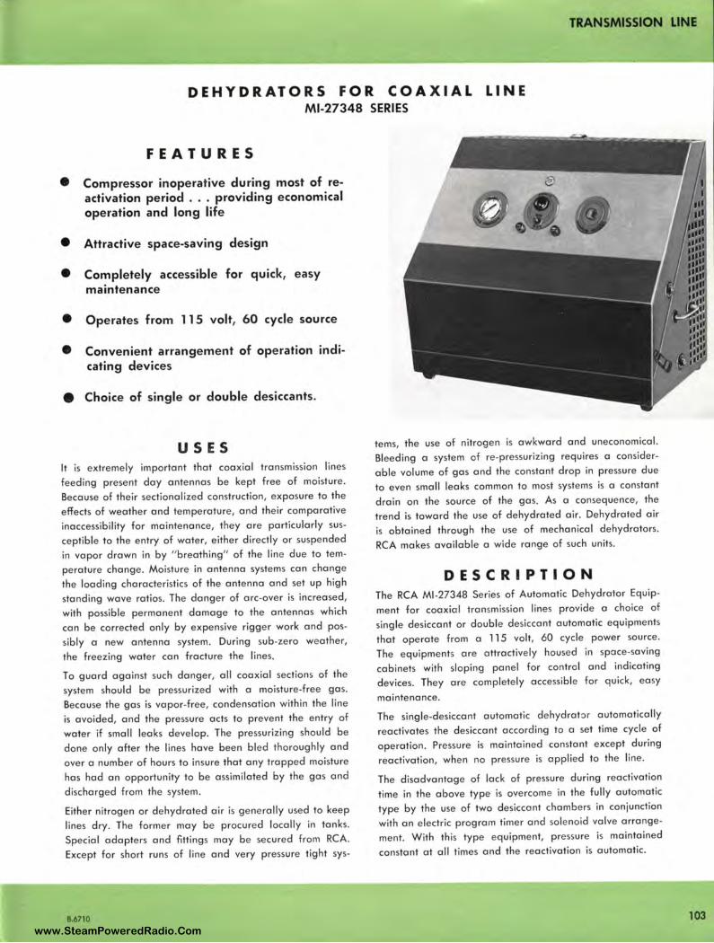
TRANSMISSION LINE
DEHYDRATORS FOR COAXIAL LINE Ml-27348 SERIES
FEATURES
• Compressor inoperative during most of reactivation period . .. providing economical operation and long life
• Attractive space-saving design
• Completely accessible for quick, easy maintenance
• Operates from 115 volt, 60 cycle source
• Convenient arrangement of operation indicating devices
• Choice of single or double desiccants.
USES It is extremely important that coaxial transmission lines
feeding present day antennas be kept free of moisture.
Beca use of their sectionalized construction, exposure to the
effects of weather and temperature, and their comparative
inaccessibility for maintenance, they are particularly sus
ceptible to the entry of water, either d irectly or suspended
in vapor drawn in by " breathing" of the line due to tem
perature change. Moisture in antenna systems can change
the loading characteristics of the antenna and set up high
stand ing wave ratios. The danger of arc-over is increased,
with possible permanent damage to the antennas which
can be corrected only by expensive rigger work and pos
sibly a new antenna system. During sub-zero weather,
the freezing water can fracture the lines .
To guard against such danger, all coaxial sections of the
system should be pressurized with a moisture-free gas.
Beca use the gas is vapor-free , condensation within the line
is avoided, and the pressure acts to prevent the entry of
water if small lea ks deve lop. The pressurizing should be
done only after the lines have been bled thoroughly and
over a number of hours to insure that any trapped moisture
has had an opportunity to be assimilated by the gas and
discharged from the system.
Either nitrogen or dehydrated air is generally use d to keep
lines dry . The form e r may be procured locally in tanks .
Special adapters and fittings may be secured from RCA.
Except for short runs of line and very pressure tight sys-
B.6710
terns, the use of nitrogen is awkward and uneconomical.
Bleeding a system of re-pressurizing requires a consider
a b le vo lu me of gas and the constant drop in pressure due
to even sma ll leaks common to most systems is a constant
d rain on the source of the gas. As a consequence, the
trend is toward the use of dehydrated air. Dehydrated air
is obta ined throug h the use of mechanica l dehydrators.
RCA makes available a wide range of such units.
DESCRIPTION The RCA Ml-27348 Series of Automatic Dehydrator Equip
ment for coaxial transmission lines provide a choice of
si ngle desiccant or double desiccant automatic equipments
that operate from a 115 volt, 60 cycle power source.
The equipments are attractive ly housed in space-saving
cabinets with sloping panel for control and indicating
devices. They are completely accessible for quick, easy
maintenance.
The single-desiccant automatic dehydrat::>r automatically
reactiva tes the desiccant according to a set time cycle of
operation. Pressure is maintained constant except during
reactivation, when no pressure is applied to the line .
The disadvantage of lack of pressure during reactivat ion
time in the above type is overcome in the fully automatic
type by the use of two desiccant chambe rs in conjunction
with an electric program timer and sole noid valve arrange
ment. W ith this type equipment, pressure is maintained
constant at all times and the reactivation is automatic.
103 www.SteamPoweredRadio.Com
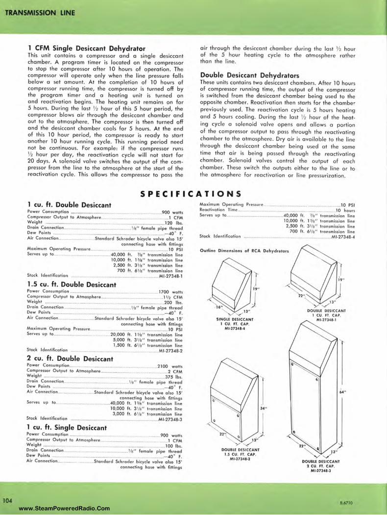
TRANSMISSION LINE
1 CFM Single Desiccant Dehydrator This unit contains a compressor and a single desiccant chamber. A program timer is located on the compressor to stop the compressor after 10 hours of operation. The compressor will operate only when the line pressure falls below a set amount. At the completion of 10 hours of compressor running time, the compressor is turned off by the program timer and a heating unit is turned on and reactivation begins. The heating unit remains on for 5 hours. During the last ½ hour of this 5 hour period, the compressor blows air through the desiccant chamber and out to the atmosphere. The compressor is then turned off and the desiccant chamber cools for 5 hours. At the end of this 10 hour period, the compressor is ready to start another 10 hour running cycle . This running period need not be continuous. For example: if the compressor runs ½ hour per day, the reactivation cycle will not start for 20 days. A solenoid valve switches the output of the compressor from the line to the atmosphere at the start of the reactivation cycle. This allows the compressor to pass the
air through the desiccant chamber during the last ½ hour of the 5 hour heating cycle to the atmosphere rather than the line.
Double Desiccant Dehydrators These units contains two desiccant chambers. After 10 hours of compressor running time, the output of the compressor is switched from the desiccant chamber being used to the opposite chamber. Reactivation then starts for the chamber previously used. The reactivation cycle is 5 hours heating and 5 hours cooling . During the last ½ hour of the heating cycle a solenoid valve opens and allows a portion of the compressor output to pass through the reactivating chamber to the atmosphere. Dry air is available to the line through the desiccant chamber being used at the same time that air is being passed through the reactivating chamber. Solenoid valves control the output of each chamber. These switch the outputs either to the line or to the atmosphere for reactivation or line pressurization.
SPECIFICATIONS
104
1 cu. ft . Double Desiccant Power Consumption ...................................................................... 900 watts Compressor Output to Atmosphere .................................................. .. 1 CFM Weight ...... ............................ .. ... .... ..................................... ... .. .. .. ... 120 lbs . Drain Connection .................................................... 1/s" female pipe thread Dew Points ................................. ....... ............................................. - 40° F. Air Connection ............................ Standard Schrader bicycle valve also 15'
connecting hose with fittings Maximum Operating Pressure ..................................... ....................... 10 PSI Serves up to .......................................... .40,000 ft. 7/s" transmission line
10,000 ft . 1 %" transmission line 2,500 ft . 31/s" transmission line
700 ft. 6 1/s" transmission line Stock Identification ........................... .... .................................... Ml -27348-1
1.5 cu. ft. Double Desiccant Power Consumption .................................................................... 1700 watts Compressor Output to Atmosphere ................................................ 1 ½ CFM Weight ................................................................. ..... .......... .. .......... 200 lbs. Drain Connection .................................................... 1/s" female pipe thread Dew Points .... ..................................... ... ... ................................... .... - 40° F. Air Connection ............................ Standard Schrader bicycle valve also 15'
connecting hose with fittings Maximum Operating Pressure ............................................................ 1 O PSI Serves up to ............................................ 20,000 ft. 1 %" transmission line
5,000 ft. 3 1/s" transmission line 1,500 ft. 6 1/s" transmission line
Stock Identification ................................................................... Ml -27348•2
2 cu. ft. Double Desiccant Power Consumption........................................................... .. ..... 2100 watts Compressor Output to Atmosphere .................................................... 2 CFM Weight .............................................................................................. 375 lbs. Drain Connection .................................................. 1/s" female pipe thread Dew Points ...................................................................................... - 40 ° F. Air Connection ............................ Standard Schrader bicycle valve also 15'
connecting hose with fittings Serves up to ......................................... .40,000 ft. 1 %" transmission line
10,000 ft. 3 1/s" transmission line 3,000 ft . 6 1/s" transmission line
Stock Identification .................................................................... Ml•27348•3
1 cu . ft . Single Desiccant Power Consumption ................................................... .. .. ........ 900 watts Compressor Output to Atmosphere .................................................... 1 CFM Weight .............................................................................................. 100 lbs. Drain Connection ................................................. 1/s" female pipe thread Dew Points ........................................ ......................................... ..... - 40 ° f . Air Connection ........................... Standard Schrader bicycle valve also 15'
connecting hose with fittings
Maximum Operat ing Pressure ........................................................... 10 PSI Reactivation Time ............................................................................ 10 hours Serves up to ........................................... .40,000 ft. ~8" transmission line
10,000 ft . 1 %" transm ission line 2,500 ft . 3 1/s" transmission line
700 ft . 6 1/s" transmission line Stock Identification ........................ ............................................ Ml -27348-4
Outline Dimensions of RCA Dehydrators
'< 13"
SINGLE DESICCANT 1 CU. FT. CAP.
Ml•27348•4
DOUBLE DESICCANT 1.S CU. FT. CAP.
M1•27348·2
DOUBLE DESICCANT 1 CU. FT. CAP.
Ml •2734B•l
0
64"
DOUBLE DESICCANT 2 CU. FT. CAP.
Mt.27348·3
B.6710
www.SteamPoweredRadio.Com
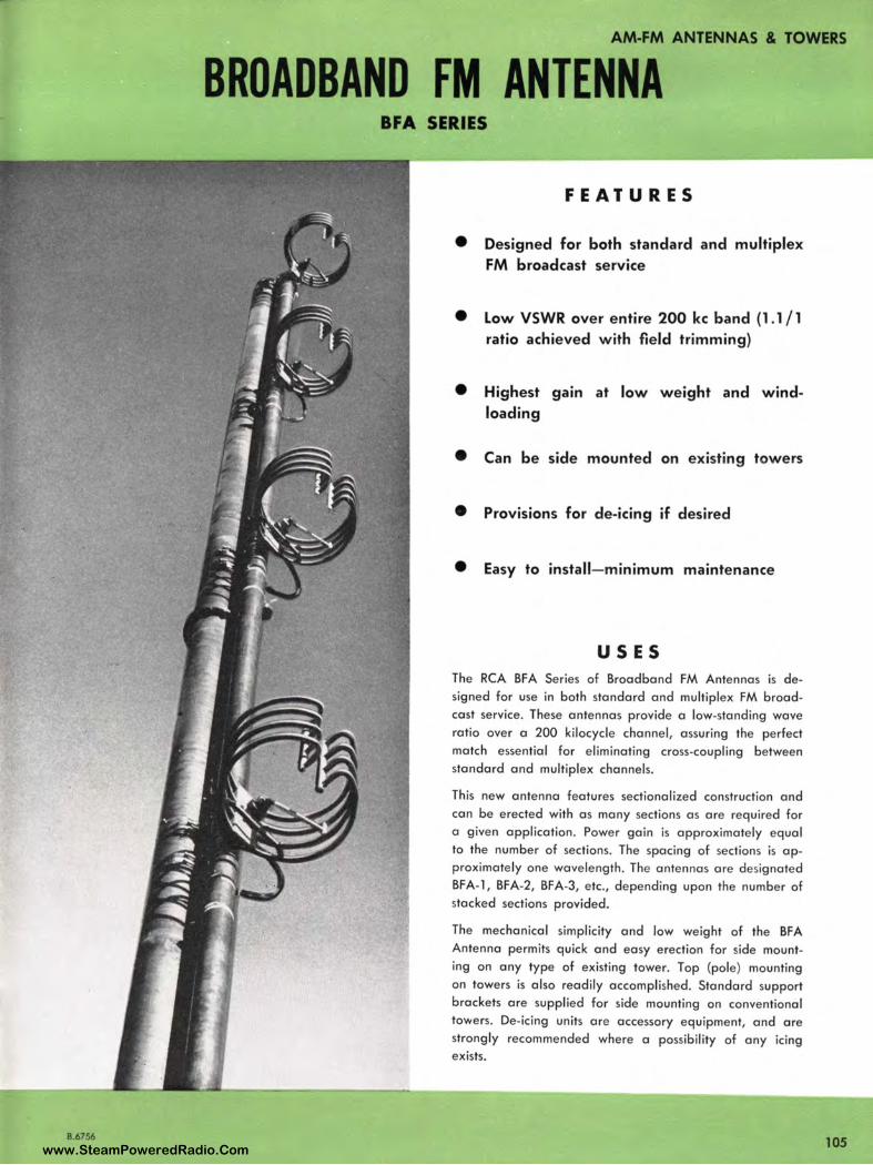
8.6756
AM-FM ANTENNAS & TOWERS
BROADBAND FM ANTENNA BFA SERIES
FEATURES
• Designed for both standard and multiplex FM broadcast service
• Low VSWR over entire 200 kc band (1.1 / 1 ratio achieved with field trimming)
• Highest gain at low w eight and windloading
• Can be side mounted on existing towers
• Provisions for de-icing if desired
• Easy to install-minimum maintenance
USES The RCA BFA Series of Broadband FM Antennas is designed for use in both standard and multiplex FM broadcast service. These antennas provide a low-standing wave ratio over a 200 kilocycle channel, assuring the perfect match essential for eliminating cross-coupling between standard and multiplex channels.
This new antenna features sectionalized construction and can be erected with as many sections as are required for a give n application. Power gain is approximately equal to the number of sections. The spacing of sections is approximate ly one wavelength. The antennas are designated BFA-1, BFA-2, BFA-3, etc., depending upon the number of stacked sections provided.
The mechanical simplicity and low weight of the BFA Antenna permits quick and easy erection for side mounting on any type of existing tower. Top (pole) mounting on towers is also readily accomplished. Standard support brackets are supplied for side mounting on conventional towers. De-icing units are accessory equipment, and are strongly recommended where a possibility of any icing exists.
105 www.SteamPoweredRadio.Com
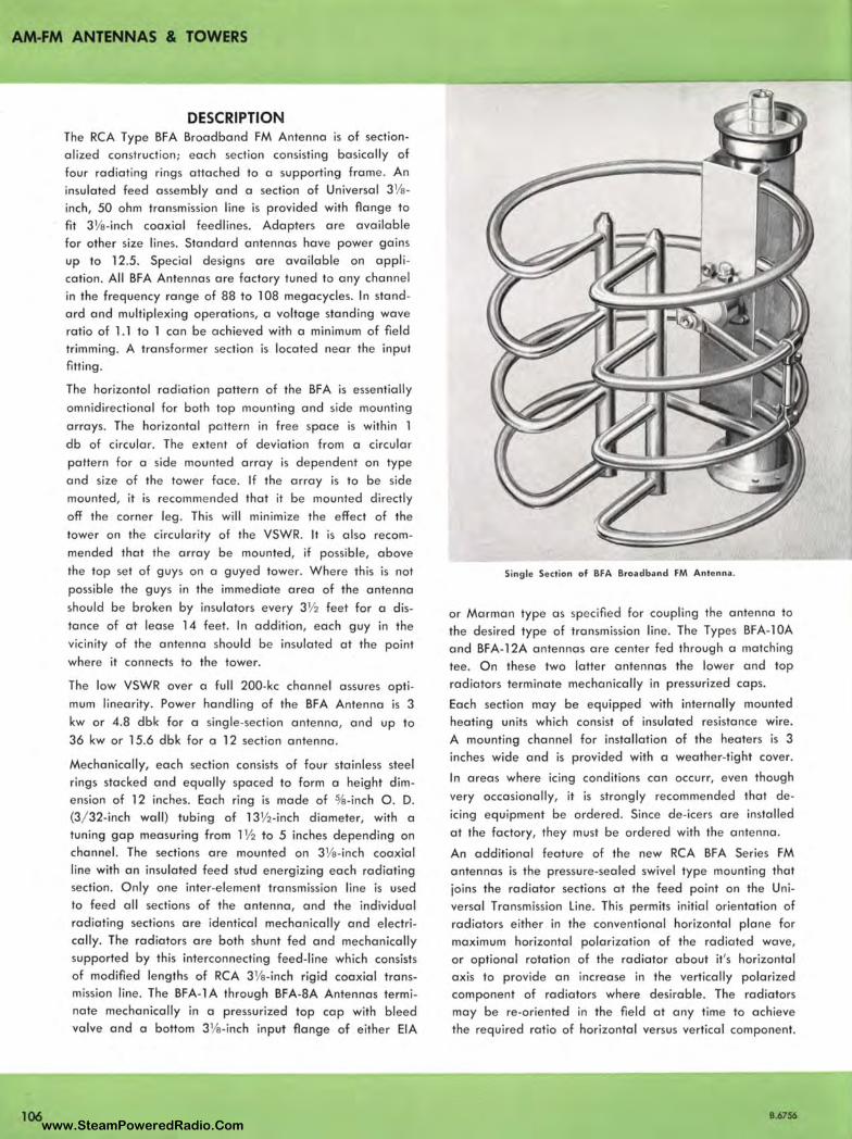
AM-FM ANTENNAS & TOWERS
106
DESCRIPTION The RCA Type BFA Broadband FM Antenna is of section
alized construction; each section consisting basically of
four radiating rings attached to a supporting frame . An
insulated feed assembly and a section of Universal 31/a
inch, 50 ohm transmission line is provided with flange to
fit 31/a-inch coaxial feedlines . Adapters are available
for other size lines. Standard antennas have power gains up to 12.5. Special designs are avai lable on appli
cation. All BFA Antennas ore factory tuned to any channel
in the frequency range of 88 to 108 megacycles. In stand
ard and multip lexing operations, a voltage standing wave ratio of l . l to l can be achieved with a minimum of fie ld
trimming . A transformer section is located near the input fitting.
The horizontol radiation pattern of the BFA is essentially
omnidirectional for both top mounting and side mounting
arrays. The horizontal pa tte rn in free space is within l
db of circular. The extent of deviation from a circular
pattern for a side mo unted array is de pendent on type
and size of the tower face. If the array is to be side
mounted, it is recomme nded that it be mounted directly
off the corner leg. This will minimize the effect of the
tower on the circularity of the VSWR. It is also recom
mended that the array be mounted, if possible, above
the top set of g uys on a guyed tower. Where this is not
possible the guys in the immediate area of the antenna
should be broken by insulators every 3½ feet for a dis
tance of at lease 14 feet . In addition, each guy in the
vicinity of the antenna should be insulated at the point
where it connects to the tower.
The low VSW R over a full 200-kc channel assures opti
mum linearity. Power handling of the BFA Antenna is 3
kw or 4.8 dbk for a single-section antenna , and up to
36 kw or 15.6 dbk for a 12 section antenna .
Mechanically, each section consists of four stainless steel
rings stacked and equally spaced to form a height dim
ension of 12 inches. Each ring is made of %-inch 0 . D.
(3/ 32-inch wall) tubing of 13½-inch diameter, with a tuni ng gap measuring from l ½ to 5 inches depending on
channel. The sections are mounted on 31/a-inch coaxial
line with an insulated feed stud energizing each radiating section. O nly one inter-element transmission line is used
to feed all sections of the antenna, and the individual
radiating sections are identical mechanically and electri
cally. The radiators are both shunt fed and mechanically
supported by this interconnecting feed-line which consists
of modified lengths of RCA 31/a-inch rigid coaxial transmission line. The BFA-1 A through BFA-8A Antennas termi
nate mechanically in a pressurized top cap with bleed
valve and a bottom 31/a-inch input flange of either EIA
Single Section of BFA Broadband FM Antenna .
or Morman type as specified for coupling the ante nna to
the desired type of transmission line. The Types BFA-l0A
and BFA-l 2A antennas are cente r fed through a matching
tee. O n these two latter antennas the lowe r and top radiators terminate mechanically in pressurized caps.
Each section may be equipped with internally mounted heating units which consist of insulated resistance wire.
A mo unting channel for installation of the heaters is 3
inches wide and is provided with a weather-tight cover.
In areas where icing conditions can occurr, even though
very occasionally, it is strongly recommended that de
icing equipment be ordered . Since de-icers are installed
at the fac tory, they must be ordered with the antenna .
An additional feature of the new RCA BFA Series FM antennas is the pressure-sealed swivel type mounting that
joins the radiator sections at the feed point on the Uni
versal Transmission Line. This permits initial orientation of
ra d iators either in the conventiona l horizontal plane for
maximum horizontal po larization of the radiated wave,
or optional rotation of the radiator about it's horizontal
axis to provide an increase in the vertically polarized component of radiators where desirable . The radiators
may be re-oriented in the field at any time to achieve
the required ratio of horizontal versus vertical component.
B.6756 www.SteamPoweredRadio.Com
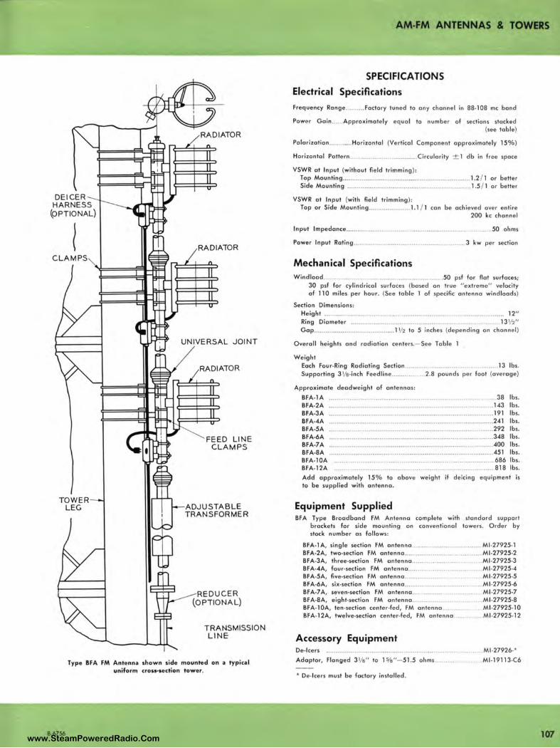
DEICER HARNESS
(OPTIONAL)
I
TOWER LEG ADJUSTABLE
TRANSFORMER
TRA NSMISSION LINE
Type BFA FM Antenna show n side mounted on a ty pical
uniform c:ro1•1ection tower.
B.6756
AM-FM ANTENNAS & TOWERS
SPECIFICATIONS
Electrical Specifications
Frequency Range ....... ... Factory tuned lo any channel in 88-108 me band
Power Gain ...... Approximate ly equal to number of sections slacked
(see table)
Polorizalion ............ Horizontal (Vertical Component approximately 15%)
Horizontal Pattern ...... ...... ..... .......... ........ Circularity ± 1 db in free space
VSWR al Input (without field trimming ):
Top Mounting .. ...... ..... ..... .................. ..... ..... ... ....... ........ .. .. 1.2 / 1 or better
Side Mounting ....... ..... ....... ... ....... ........ ................ .. ........... 1.5 / 1 or better
VSWR al Input (with field t rimming ):
Top or Side Mounting ........ .. ... ....... .. 1.1 / 1 can be achieved over entire
200 kc channel
Input lmpedance ...... ......... .. .... ................ ..... ... .................... ............. 50 ohms
Power Input Rating ... . ...... ........ .. ................ .... .. ............... 3 kw per section
Mechanical Specifications
Windload..................... . .......... .. .................... 50 psf for flat surfaces;
30 psi far cylindrical surfaces (based on true "extreme" velocity
of 110 miles per hour. (See table 1 of specific antenna windloads)
Section Dimensions :
Height ........... .... ........... ....... ........ ....... ... ..... .................................. ..... 12"
Ring Diameter .. ...... ....... .. ........ .. ....... .................. .. ....................... 13½"
Gap ....... .. ............. ... ........ .. .... .... 1 ½ lo 5 inches (depending on channel )
Overall heights and radiation ce nlers.- See Table 1
Weight
Each Four-Ring Radiating Section............ . .. ............................... 13 lbs.
Supporting 3 1/e-inch Feedline..... .. ...... 2.8 pounds per foot (average)
Approximate deadweight of antennas:
BFA-lA ............. ................. .... .... ... ................................ . ... 38 lbs.
BFA-2A ...... ........... ....... ... ....... .. ...... ...................... ................ ........ 143 lbs.
BFA--3A .... ..... ... ............. ............ .. ................ .. ........ .. .......... ....... ... 191 lbs.
BFA-4A ............ ............................. ......... .......... ......... ........... ........ 241 lbs.
BFA-5A .. ..... ..... ..... ... .... .. .... ...... ........ .. ......... ......... .................... .. . 292 lbs.
BFA-6A .............. ...... ............ ..... .. ........... .... ...... ..... ..... ... .. ...... ...... . 348 lbs.
BFA-7 A ........ ..... ..................... .............. .......... ...•......................... .400 lbs.
BFA-8A ....... .......... .. .... ........ ..... ............... .... ......... ........................ 451 lbs.
BFA-l0A ....... ... ............... .................... ..................... ................... 686 lbs.
BFA-12A .. .......... ............. ............. ... ......... .............................. ... ... 818 lbs.
Add approximately 15% lo obove weig ht if deicing equipment is
to be supplied with antenna .
Equipment Supplied BFA Type Broadband FM Ante nna complete with standard suppo rt
brackets for side mounting on conventional lowers. Order by
stock number as follows :
BFA-1 A, single section FM antenna ..... .............................. MJ .27925· 1
BFA·2A, two-section FM antenna ... .. ............... .................. .. Ml -27925•2
BFA-3A, three-section FM antenna ......... ........................... MJ .27925•3
BFA-4A, four-section FM anten na ........................ ......... . .. Ml -27925•4
BFA·5A, five•section FM antenna ........... .. ... ............. . ... Ml -27925-5
BFA-6A, six•section FM antenna .. ........... .......................... Ml -27925•6
BFA-7 A, seven-section FM antenna ... .... .... .... ..... Ml -27925•7
BFA-8A, eight-section FM antenna ........... ........ .. . .. MJ .27925•8
BFA• 1 0A, len•section center-fed, FM antenna ..... ....... . ... Ml -27925• l 0
BFA-12A, lwelve•sect ion ce nter-fed, FM antenna ............... MJ .27925-12
Accessory Equipment De-icers ... .. ... ........... ..... .... .... .... .... ...... ... ............ ............... . .. MJ .27926•*
Adaptor, Flanged 3 1/e" to 1%"-51 .5 ohms ....... ............... Ml -19113.(6
• De· lcers must be factory installed.
107 www.SteamPoweredRadio.Com
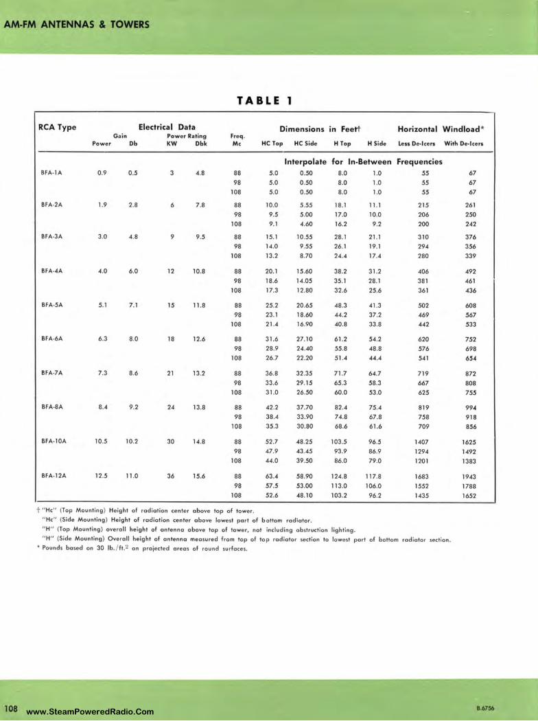
AM-FM ANTENNAS & TOWERS
TABLE 1
RCA Type Electrical Data Dimensions in Feett Horizontal Windload * Gai n Power Rating Freq .
Power Db KW Dbk Mc HC Top HC Side H Top H Side Less De- icers With De- icers
Interpolate for In-Between Frequencies BFA-lA 0.9 0.5 3 4.8 88 5.0 0.50 8.0 1.0 55 67
98 5.0 0.50 8.0 1.0 55 67
108 5.0 0.50 8.0 1.0 55 67
BFA-2A 1.9 2.8 6 7.8 88 10.0 5.55 18.1 11.1 215 261
98 9.5 5 .00 17.0 10.0 206 250
108 9.1 4.60 16.2 9.2 200 242
BFA-3A 3.0 4.8 9 9.5 88 15.1 10.55 28.1 21.1 310 376
98 14.0 9.55 26.1 19.1 294 356
108 13.2 8.70 24 .4 17.4 280 339
BFA-4A 4.0 6.0 12 10.8 88 20.1 15.60 38.2 31.2 406 492
98 18.6 14.05 35.1 28.1 381 461
108 17.3 12.80 32.6 25.6 361 436
BFA-5A 5.1 7.1 15 11.8 88 25.2 20.65 48.3 41 .3 502 608 98 23 .1 18.60 44.2 37.2 469 567
108 21.4 16.90 40.8 33.8 442 533
BFA-6A 6.3 8.0 18 12.6 88 31.6 27.10 61.2 54.2 620 752 98 28.9 24.40 55.8 48.8 576 698
108 26.7 22.20 51.4 44.4 541 654
BFA-7A 7.3 8.6 21 13.2 88 36.8 32.35 71.7 64.7 719 872 98 33.6 29.15 65.3 58.3 667 808
108 31.0 26.50 60.0 53.0 625 75.'l
BFA-8A 8.4 9.2 24 13.8 88 42.2 37.70 82.4 75.4 819 994
98 38.4 33 .90 74.8 67.8 758 918 108 35.3 30.80 68.6 61.6 709 856
BFA-l0A 10.5 10.2 30 14.8 88 52.7 48.25 103.5 96.5 1407 1625 98 47.9 43.45 93.9 86.9 1294 1492
108 44.0 39.50 86.0 79.0 1201 1383
BFA-12A 12.5 11 .0 36 15.6 88 63.4 58.90 124.8 117.8 1683 1943
98 57.5 53.00 113.0 106.0 1552 1788 108 52.6 48.10 103.2 96.2 1435 1652
t " He" (Top Mounting ) Height of rodiatian center above top of tower. " He" (Side Mounting ) Height of radiation center above lowest part of bottom radiator. " H" (Top Mounting ) overall height of antenna above lop of tower, not including obstruction lighting . " H" (Side Mounting) Overall height of antenna measured from lop of top radiator section lo lowest part of bottom radiator section.
• Pounds based on 30 lb./ft .2 on projected areas of round surfaces.
108 B.6756 www.SteamPoweredRadio.Com
wigfi
Stolen 2 Line Transparent
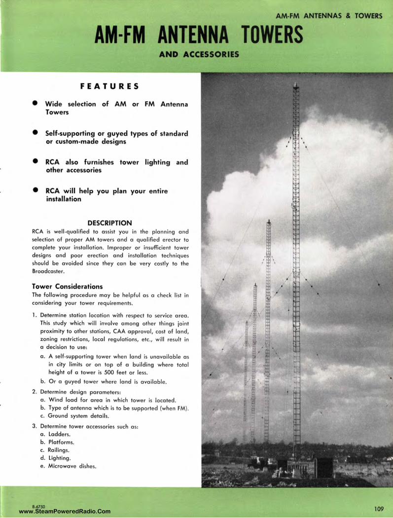
AM-FM ANTENNAS & TOWERS
AM-FM ANTENNA TOWERS AND ACCESSORIES
FEATURES
• Wide selection of AM or FM Antenna Towers
• Self-supporting or guyed types of standard or custom-made designs
• RCA also furnishes tower lighting and other accessories
• RCA will help you plan your entire installation
DESCRIPTION RCA is well -qualified to assist you in the planning and selection of proper AM towers and a qualified erector to complete your installation. Improper or insufficient tower designs and poor erection and installation techniques should be avoided since they can be very costly to the Broadcaster.
Tower Considerations The following procedure may be helpful as a check list in considering your tower requirements.
1. Determine station location with respect to service area . This study which will involve among other things joint proximity to other stations, CAA approval, cost of land, zoning restrictions, local regulations, etc., will result in a decision to use:
a. A self-supporting tower when land is unavailable as in city limits or on top of a building where total height of a tower is 500 feet or less.
b. Or a guyed tower where land is available.
2. Determine design parameters: a. Wind load for area in which tower is located. b. Type of antenna which is to be supported (when FM). c. Ground system details.
3. Determine tower accessories such a s: a . Ladders. b. Platforms. c. Railings. d. Lighting. e . Microwave dishes.
8.6750 109 www.SteamPoweredRadio.Com
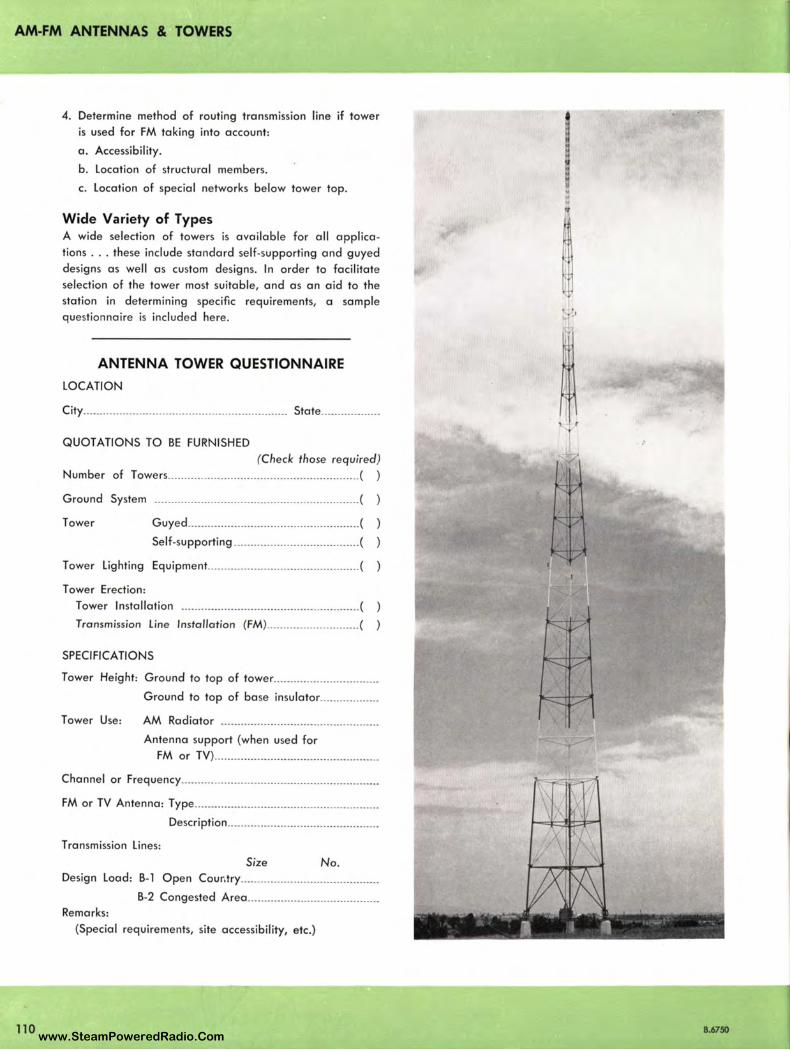
AM-FM ANTENNAS & TOWERS
110
4. Determine method of routing transmission line if tower is used for FM taking into account:
a. Accessibility.
b. Location of structural members.
c. Location of special networks below tower top.
Wide Variety of Types A wide selection of towers is available for all applica
tions . .. these include standard self-supporting and guyed designs as well as custom designs. In order to facilitate selection of the tower most suitable, and as an aid to the station in determining specific requirements, a sample questionnaire is included here.
ANTENNA TOWER QUESTIONNAIRE
LOCATION
City .............................................................. State ..... ....... ..... .
QUOTATIONS TO BE FURNISHED
(Check those required) Number of Towers ................................................ .......... ( )
Ground System .... ............ .............................................. (
Tower Guyed ........... ......................................... (
Self-supporting ...................................... (
Tower Lighting Equipment .............................................. (
Tower Erection:
Tower Installation ...................................................... (
Transmission Line Installation (FM) ............................ (
SPECIFICATIONS
Tower Height: Ground to top of tower ............................... .
Ground to top of base insulator ............... .. .
Tower Use: AM Radiator ............................................... .
Antenna support (when used for FM or TV) ......... ....................................... . .
Channel or Frequency ........................................................... .
FM or TV Antenna: Type .............. ..... .................................... .
Description .............................. ............... .
Transmission Lines:
Size No. Design Load: B-1 Open Cou r,try .... ......................... ............ .
B-2 Congested Area ....................................... . Remarks:
(Special requirements, site accessibility, etc.)
.. ., ., .,
, "
8.6750 www.SteamPoweredRadio.Com

Guyed Towers Relatively flat country with low surrounding hills lends itself well to the insta ll ation of ta ll structures. W here land area permits, towers are usually guyed and the usual cross sectional shape is triangu lar so that three point guying can be used . Guyed tower costs are normally lower than for self-supporting structures beca use less steel is used .
A useful method for estimating the land required for a guyed structure is to consider the distance to the farthest guy anchorage as being approximately 70% the tower
height.
Self-Supporting Towers Self-supporting towers are especially advantageous in city and congested districts where land is expensive. For estimating requ ired space for a se lf-supporting tower, the distance between tower legs can normally be considered
as l / 8 the height of the structure.
Tower Construction In both types of antenna syste ms a check for plumb and
for proper guy tension should be made in order to obtain
the required radiation patterns. Insofar as directional sys
tems are concerned, the towers should be as nearly identi
cal as possible with respect to guy wire, height, azimuth
location, positioning of guy insulators, etc. No section of
guy wire should be greater than a 1/s wavelength of the
operating frequency in order not to affect the radiation
pattern. After the towers have been erected, all joints
should be weld-bonded to assure a continuous stee l radiator.
Steel towers may be hot dip galvanized, where corrosive
action due to fumes, salt air, etc., are likely to occur. All
towers should be painted to conform with FCC and CAA regulations.
Climbing ladders, when used, should be located inside the
tower if at all possib le and preferably near the tower
legs . By placing the ladder within the tower, lattice braces
form a safety cage for the serviceman. For FM the ladder
is also an excellent support for transmission line runs a s
it is accessible at all times. The type of hange rs (usually direct mounting) should be specified so that proper sup
porting members can be provided in the tower.
!1.6750
AM-FM ANTENNAS & TOWERS
111 www.SteamPoweredRadio.Com

AM-FM ANTENNAS & TOWERS
WIND VELOCITY AND
.!!.!...
PRESSURE MAP
NEW YORK IIJ ·10 NEWARK e2 - u -
PH IL ADELPHI A ee - 39 ATLANTI C. CITY 91 -~ BALTIMORE 80 - ~
WA SHINGTON t2 · R
ez- !!!
~ - 01St0NATIS ()(ll(M( WINO
YllO<ITY {fAUIST MIU AS llCOtOlO IY U S
W(ATHH IUllAU fOt THI PUUCUl.AR Clf't
SECOND NUMIU UNDU llN(O - OISIGNATIS U l VATION 0,
U S WIATHll IUltlAU AIOVl SIA, UVU flUT NOT
ANIMOMITU HltCHl .J
112
,. , ,.s1n1 Mill 1"110 (» IHI IA UUI Mill 0, All fA \\IN(;
$$1H( OISIGN OAI A I\ IA"O OH UI\TtNG
ll(OltOS ANO UUOIU. IUI IS NOi INOl(,UIV(
OJ •uru •1 III NOS
Publishe d records of the U. S. Wea ther Bureau are given as " maximum" (S minute average velocity) or "extreme" (the speed of the fastest mile of
air passing the anemometer). The selection of design loads should be based on "extreme" velocity. If no data is available on "extreme", the pub•
lished " maximum" figures should be increased by approximately 20%.
The plotte d areas shown on the map are de rived from careful studies ma de by authorities in this field and the information is based on monthly
and yearly average velocities, freque ncy of occurrence, probability of extremes, topographical conditions, etc.
Installations on mountain tops and areas subject to heavy icing conditions should be given special consideration. Building codes and zoning ordi
nances should also be carefully investigated.
Wind Load
Towers must be designed and installed to safely withstand
the maximum wind velocities that may be encountered.
Experienced tower builders rarely design for less than a
30/ 20 lb. loading. This means that the tower members are
designed to resist a horizontal wind pressure of 30 lbs.
per ~quare foot of projected area on all flat surfaces and
20 lbs. on round surfaces. This is the equivalent of an
actual wind velocity of 85 miles per hour.
Specifications Towers are designed in accordance with RETMA specifica
tions. Consultation with RCA Broadcast Representatives will
help to determine your requirements. Call or write you r
nearest representative.
B.6750 www.SteamPoweredRadio.Com
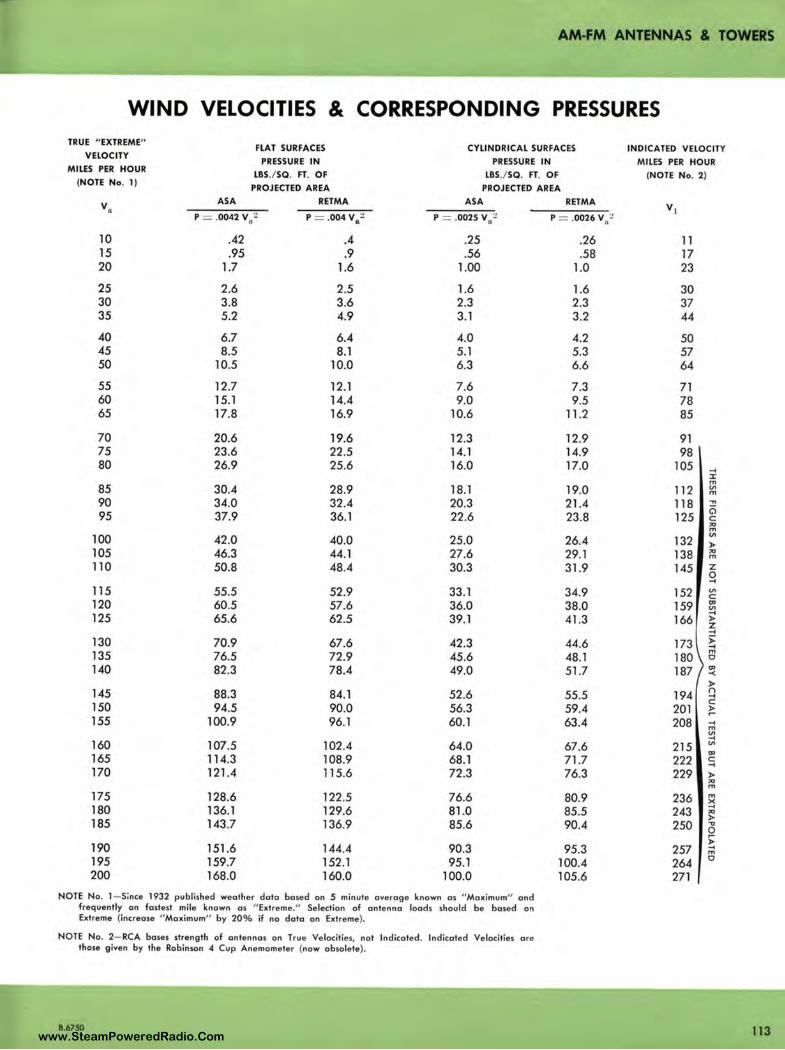
AM-FM ANTENNAS & TOWERS
WIND VELOCITIES & CORRESPONDING PRESSURES TRUE "EXTREME"
FLAT SURFACES CYLI NDRICAL SURFACES INDICATED VELOCITY VELOCITY
PRESSURE IN PRESSURE IN MILES PER HOUR MILES PER HOUR
LBS./SQ. FT. O F LBS./SQ. FT. OF (NOTE No. 2) (NOTE No. 1)
PROJECTED AREA PROJECTED AREA
vn ASA RETMA ASA RETMA V1
P = .0042 v,,2 P = .004 Va~ P = .0025 V8
:! P = .0026 V/
10 .42 .4 .25 .26 11 15 .95 .9 .56 .58 17 20 1.7 1.6 1.00 1.0 23
25 2.6 2.5 1.6 1.6 30 30 3.8 3.6 2.3 2.3 37 35 5.2 4.9 3.1 3.2 44
40 6.7 6.4 4.0 4.2 50 45 8.5 8.1 5.1 5.3 57 50 10.5 10.0 6.3 6.6 64
55 12.7 12.1 7.6 7.3 71 60 15.1 14.4 9.0 9.5 78 65 17.8 16.9 10.6 11.2 85
70 20.6 19.6 12.3 12.9 91 75 23.6 22.5 14.1 14.9 98 80 26.9 25.6 16.0 17.0 105 ...
:i: m
85 30.4 28.9 18.1 19.0 112 "' m
90 34.0 32.4 20.3 21.4 118 .,, 0 95 37.9 36.1 22.6 23 .8 125 C
"' m
100 42.0 40.0 25.0 26.4 132 "' > 105 46.3 44.1 27.6 29.1 138 "' m
110 50.8 48.4 30.3 31.9 145 z 0 ...
115 55.5 52.9 33.1 34.9 152 "' C 120 60.5 57.6 36.0 38.0 159 "' "' 125 65.6 62.5 39.1 41.3 166
... > z ...
130 70.9 67.6 42.3 44.6 173 ;;:: ... 135 76.5 72.9 45.6 48.1 180
m 0
140 82.3 78.4 49.0 51.7 187 "' -< >
145 88.3 84.1 52.6 55.5 194 ('\ ...
150 94.5 C
90.0 56.3 59.4 201 '!! 155 100.9 96.1 60.1 63.4 208 ...
m
"' ... 160 107.5 102.4 64.0 67.6 215 "'
"' 165 114.3 108.9 68.1 71.7 222 C ... 170 121.4 115.6 72.3 76.3 229 >
"' m
175 128.6 122.5 76.6 80.9 236 m X
180 136.1 129.6 81.0 85.5 243 ... ~
185 143.7 136.9 85.6 90.4 250 "" 0
190 • 151.6 144.4 90.3 95.3 257 ... m
195 159.7 152.1 95.1 100.4 264 0
200 168.0 160.0 100.0 105.6 271
NOTE No. 1- Since 1932 published weather data based on 5 minute average known as " Maximum" and frequently an fastest mile known as " Extreme." Selection of antenna loads should be based on Extreme (increase " Maximum" by 20% if no data an Extreme).
NOTE No. 2- RCA bases strength of antennas on True Velocit ies, not lndicoted. lndicoted Velocities are those given by the Robinson -4 Cup An emometer (now obsolete),
B.6750 113 www.SteamPoweredRadio.Com
~-FM ANTENNAS & TOWERS
114
Tower Accessory Equipment A number of tower accessories to complete the various
type RCA AM and FM Broadcast Towers are available for
all applications- these include tower grounding acces
sories, transmission lines and hangers, dehydrators, sam
pling lines, antenna feed lines, tower lighting equipment,
hazard markers, weatherproof housings, and many mis
cellaneous items such as photo-cells, lighting transformers,
and choke coils.
Ground Systems Since the radiation pattern is computed on the basis of a
perfectly conducting plane earth, and since earth's con
ditions depart radically from this assumption , a ground
system of buried copper wires or ribbons must be in
stalled in order lo approach this ideal as closely as possi
ble. The FCC minimum requirements consist of buried radial
wires at least ¼ wavelength long. They should be as
evenly spaced as practicable and in no event should less
than 90 radials be used. This is a minimum FCC require
ment and where possible a better ground system should
be installed. A properly installed and adequate ground
system can contribute much to the efficiency and stability
of a radiation pattern and actual specifications for in
stallation should be determined by the consultant.
It is suggested that a ground screen be used if high base
currents are encountered. It should be placed in position
at the base of the tower. This ground screen should be 23
gauge, expanded copper mesh, or equal. Each radial wire
must be electrically bonded to the ground screen. There
will be some installations in which the consultant will sug
gest the use of additional radials in lieu of the copper
ground screen. They should be placed around the base
of each tower and all radials used should be bonded to a
heavy bus consisting of a copper ribbon three inches or
more wide, or to a bundle of seven copper wires next
to the concrete base of the tower. The insulator base and
the lightning gap are bonded to the screens or to the
bus around the concrete tower base. It is recommended
that a No. l O soft drawn copper wire be utilized for the
radials and for the bundle of wires making up the bus.
Transmission Lines and Hangers Careful consideration should be given to the layout and
support of transmission line. Outline drawings with di
mensions are available for all types of transmission lines
and should be used in making a layout. There are two
types of transmission line hangers. One type can be wrap
locked to the tower member, another type is bolted to
the tower members. (See RCA Transmission Line and
Hanger Catalogs.)
Sampling Lines Coaxial lines of either semirigid or flexible type may be
employed for a sampling system. All lines should be the
same electrical length, whichever type is employed, in
order to obtain correct phase indication; i.e., all lines must
be of the same length as the longest line from antenna
to phase monitor. The excess line on the shorter runs may
be coiled and stored at either the antenna or the phase
monitor end. Alternatively, it may be folded back upon
itself.
The characteristic impedance of the transmission line must
be chosen to match the input impedance of the particular
type of phase monitor employed. These transmission lines,
either semirigid or flexible, can be buried in the ground
or carried back in the same trough that supports the trans
mission line . If the semirigid type is used, suitable pro
vision should be made for variations in length due to
temperature changes. The semirigid type of concentric
line utilizes dry air as the dielectric. The air in these lines
must be kept dry and provision should be made so that
dry air can be flushed through the line and held at a
pressure recommended for the transmission line used.
Sampling accessories and methods of sampling are de
scribed in the RCA Phasing Equipment Catalog.
If isolation coils are requested or required, sampling cable
or air-dielectric coax can be wrap-locked to the tower
members and then connected to the isolation coils main
tained in the tuning house at the base of the tower. From
the isl oation coil, the cab le is connected to the phase
monitor in the transmitter building . The cold end of the
isolation coil should be bonded to the ground system.
Actual specification for method and type of sampling
system and type of transmission line should be determined
by the consultant.
Antenna Feed Line Line-termintaing units can be connected to the tower by
means of copper tubing . The line shou ld be flattened at
one end and drilled for connections to the antenna-tuning
unit terminal. This line is then run through a feed-through
insulator in the tuning-house wall and the line is attached
to the tower by a bolt or by brazing. At a point between
the tower and feed-through insulator, the line should be
formed into a one or two-turn coil, 12 to 18 inches in
diameter. This coil can be self-supporting and is intended
to retard lightning and aid in the breakdown at the ball
or horn gap provided at the tower base to keep lightning
discharges from damaging the equipment. (See Antenna
Feed Line Catalog.)
8.6750
www.SteamPoweredRadio.Com
wigfi
Stolen 2 Line Transparent
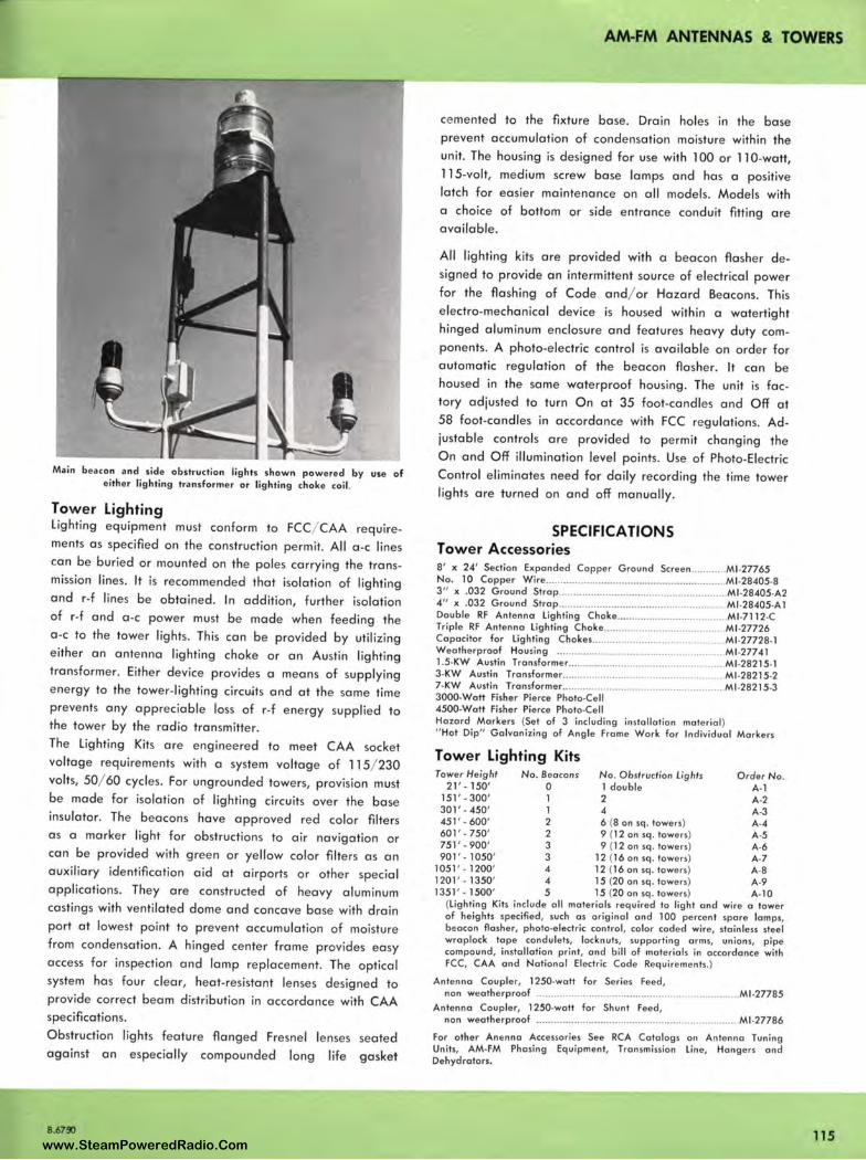
Main beacon and side obstruction lights shown powered by use of ei ther lighting transformer or lighting choke coil.
Tower Lighting Lighting equipment must conform to FCC/ CAA requirements as specified on the construction permit. All a-c lines can be buried or mounted on the poles carrying the transmission lines. It is recommended that isolation of lighting and r-f lines be obtained. In addition, further isolation of r-f and a -c power must be made when feeding the a -c to the tower lights . This can be provided by utilizing either an antenna lighting choke or an Austin lighting transformer. Either device provides a means of supplying energy to the tower-lighting circuits and at the same time prevents any appreciable loss of r-f energy supplied to the tower by the radio transmitter. The Lighting Kits are engineered to meet CAA socket voltage requirements with a system voltage of 115/ 230 volts, 50/ 60 cycles. For ungrounded towers, provision must be made for isolation of lighting circuits ove r the base insulator. The beacons have approve d red color filters as a marker light for obstructions to air navigation or can be provided with green or yellow color filters as an auxiliary identification a id at airports or other special applications. They are constructed of heavy aluminum castings with ventilated dome and concave base with drain port at lowest point to prevent accumulation of moisture from condensation. A hinged center frame provides easy access for inspection and lamp replacement. The optical system has four clear, heat-resistant lenses designed to provide correct beam distribution in accordance with CAA specifications. Obstruction lights feature flanged Fresnel lenses against an especially compounded long life
B.67~
seated
gasket
AM-FM ANTENNAS & TOWERS
ce mented to the fixture base. Drain holes in the base prevent accumulation of condensation moisture within the unit. The housing is designed for use with l 00 or 110-watt, 115-volt, medium screw base lamps and has a positive latch for easier maintenance on all models. Models with a choice of bottom or side entrance conduit fitting are available.
All lighting kits are provided with a beacon flasher designed to provide an intermittent source of electrical power for the flashing of Code and/ or Hazard Beacons. This electro-mechanical device is housed within a watertight hinged aluminum enclosure and features heavy duty components. A photo-electric control is available on order for automatic regulation of the beacon flasher. It can be housed in the same waterproof housing . The unit is fac tory adjusted to turn On at 35 foot-candl es and Off at 58 foot-candles in accordance with FCC regulations. Adjustable controls are provided to permit changing the On and Off illumination level points. Use of Photo-Electric Control eliminates need for daily recording the time tower lights are turned on and off manually.
SPECIFICATIONS Tower Accessories 8' x 24' Section Expanded Copper Ground Screen ............ Ml .27765 No. 10 Copper Wire ........................ ... ................................... Ml-28405-8 3" x .032 Ground Strop .......................................................... Ml -28405-A2 4" x .032 G round Strop ..................... ........ ............................. Ml -28405-A 1 Double RF Antenna Lighting Choke ...................................... Ml •7112-C Triple RF Ante nna Lighting Choke ......................................... Ml -27726 Capacitor for Lighting Chokes .............................................. Ml -27728• l Weatherproof Housing .. ...................................................... Ml-27741 1.5.KW Austin Transformer ............................................•....... Ml -28215• l 3-KW Austin Tronsformer ...............................................•........ Ml -28215-2 7-KW Austin Transformer ..................................................... Ml •28215-3 3000-Wott Fisher Pierce Photo•Cell 4500-Wott Fisher Pierce Photo-Cell Hazard Markers (Set of 3 including installation materia l) " Hot Dip" Galvan izing of Angle Frame Wo rk for Individual Markers
Tower Lighting Kits Tower Height No. Beacons No. Obstruction Lights Order No.
21 ' . 150' 0 1 double A-1 151 ' -300' 1 2 A-2 301' . 450' 1 4 A·3 451' . 600' 2 6 (8 on sq . towers) A-4 601 ' . 750' 2 9 (12 on sq . towers) A•5 751 ' • 900 ' 3 9 (12 on sq . towers) A·6 901 ' . 1050' 3 12 (16 on sq . towers) A•7
1051 '. 1200' 4 12 (16 on sq . towers) A-8 1201 ' • 1350' 4 15 (20 on sq . lowers) A-9 1351' . 1500' 5 15 (20 on sq . towers) A-10
(Lighting Kits include all materials required to light and wire a tower of heights specified, such os original and 100 percent spare lamps, beacon flasher, photo-e lectric control, color coded wire, stain less steel wraplock lope condulets, locknuts, supporting arms, unions, pipe compound, installation print, and bill of materials in accordance with FCC, CAA and Notio nal Electric Code Requirements.)
Antenna Coupler, 1250-watt for Series Feed, non weatherproof ................ ...................................................... Ml -27785
Antenna Coupler, 1250-wott for Shunt Feed, non weatherproof ..................... .......................... .................... Ml •27786
For other Anenna Accessories See RCA Catalogs on Antenna Tuning Units, AM-FM Phasing Equipment, Transmission Line, Hangers and Dehydrators.
115 www.SteamPoweredRadio.Com
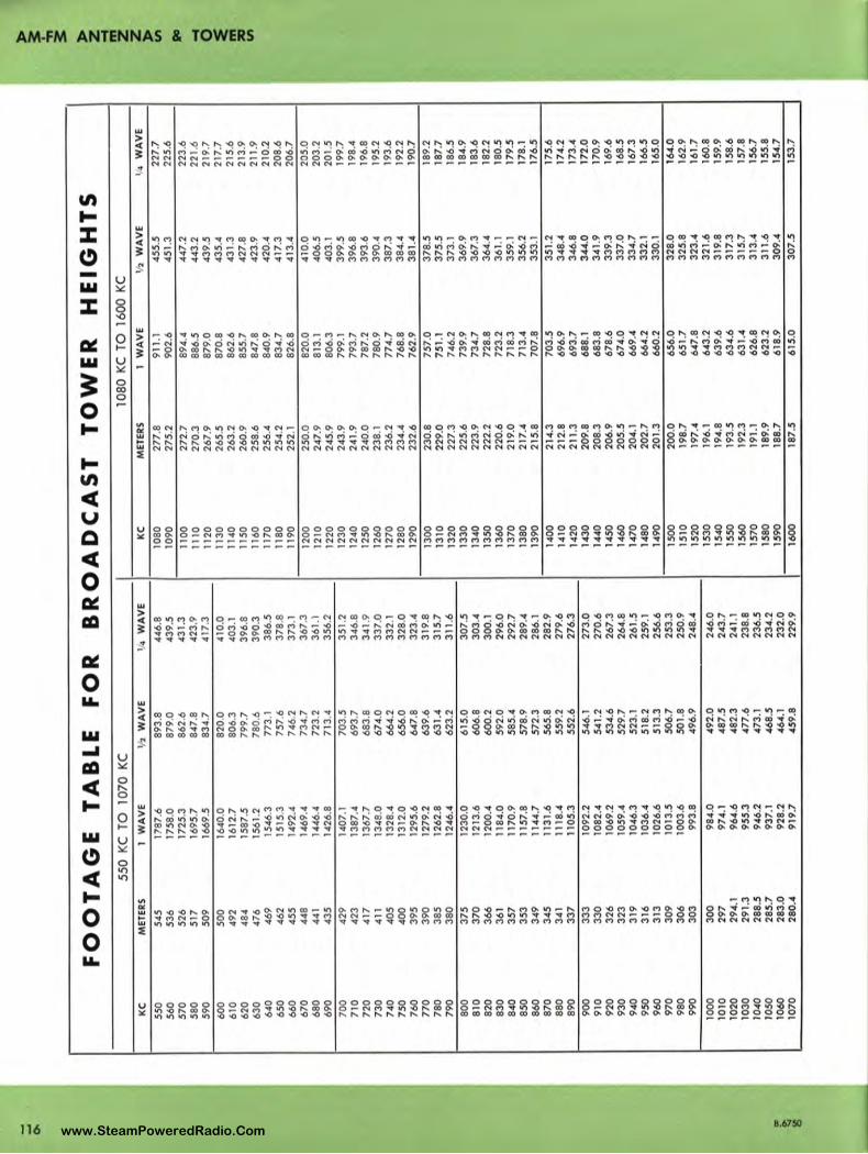
... 0.
FO
OT
AG
E
TA
BL
E
FO
R
550
KC
TO
1070
KC
KC
M
ETE
RS
1
WA
VE
½
W
AV
E
55
0
545
1787
.6
893
.8
56
0
53
6
1758
.0
879
.0
57
0
52
6
1725
.3
862
.6
580
51
7
1695
.7
847
.8
59
0
50
9
1669
.5
834.
7
600
50
0
1640
.0
820
.0
610
49
2
1612
.7
806
.3
620
484
1587
.5
799.
7 63
0 47
6 15
61.2
78
0.6
640
469
1546
.3
773
.1
650
462
1515
.3
757
.6
660
455
1492
.4
746
.2
67
0
448
1469
.4
734
.7
68
0
441
1446
.4
723
.2
69
0
435
1426
.8
713
.4
700
42
9
1407
.1
703
.5
71
0
423
1387
.4
693.
7 72
0 41
7 13
67.7
68
3.8
73
0 41
1 13
48.0
67
4.0
740
40
5
1328
.4
66
4.2
7
50
4
00
13
12.0
65
6.0
7
60
3
95
12
95.6
6
47
.8
770
390
1279
.2
63
9.6
78
0
38
5
1262
.8
631.
4 7
90
3
80
12
46.4
62
3.2
800
375
1230
.0
615
.0
810
37
0
1213
.6
60
6.8
82
0 36
6 12
00.4
60
0.2
83
0 36
1 11
84.0
59
2.0
84
0 35
7 11
70.9
58
5.4
850
353
1157
.8
578
.9
860
34
9
1144
.7
572
.3
870
345
1131
.6
565
.8
880
341
1118
.4
55
9.2
89
0 3
37
11
05.3
55
2.6
900
333
1092
.2
546.
1 9
10
3
30
10
82.4
54
1.2
920
32
6
1069
.2
534.
6 9
30
32
3 10
59.4
5
29
.7
940
319
1046
.3
523
.1
950
31
6
1036
.4
518
.2
960
313
1026
.6
513
.3
97
0
30
9
1013
.5
50
6.7
9
80
3
06
10
03.6
50
1.8
99
0
303
993.
8 49
6.9
1000
3
00
9
84.
0 49
2.0
1010
29
7 97
4.1
48
7.5
10
20
294
.1
964
.6
482
.3
1030
29
1.3
955
.3
47
7.6
10
40
288
.5
94
6.2
473
.1
5 10
50
285
.7
937
.1
468
.5
1060
28
3.0
92
8.2
46
4.1
10
70
280.
4 91
9.7
459
.8
BR
OA
DC
AS
T
TO
WE
R
HE
IGH
TS
10
80 K
C T
O
1600
KC
¼
WA
VE
K
C
ME
TER
S
1 W
AV
E
½
WA
VE
446
.8
1080
27
7.8
911
.1
45
5.5
43
9.5
10
90
275.
2 90
2.6
45
1.3
431
.3
1100
27
2.7
894
.4
447.
2 42
3.9
11
10
270
.3
886
.5
443
.2
417
.3
1120
26
7.9
87
9.0
43
9.5
41
0.0
11
30
265
.5
870
.8
435
.4
403
.1
1140
26
3.2
86
2.6
431.
3 3
96
.8
1150
26
0.9
85
5.7
427
.8
390.
3 11
60
258
.6
847
.8
423.
9 3
86
.5
1170
25
6.4
84
0.9
42
0.4
37
8.8
1180
25
4.2
83
4.7
417.
3 37
3.l
11
90
252
.1
826
.8
413
.4
367.
3 12
00
250
.0
820
.0
410
.0
361
.1
1210
2
47
.9
813
.1
406
.5
356.
2 12
20
245
.9
806
.3
403.
1 35
1.2
1230
24
3.9
79
9.1
39
9.5
346.
8 12
40
241.
9 79
3.7
396.
8 34
1.9
1250
24
0.0
78
7.2
39
3.6
33
7.0
1260
23
8.1
7
80
.9
390.
4 33
2.l
1270
23
6.2
77
4.7
38
7.3
32
8.0
1280
23
4.4
76
8.8
384.
4 32
3.4
1290
23
2.6
76
2.9
38
1.4
31
9.8
13
00
230
.8
75
7.0
37
8.5
315.
7 13
10
229
.0
751.
1 3
75
.5
311
.6
1320
22
7.3
74
6.2
37
3.l
30
7.5
1330
22
5.6
73
9.9
36
9.9
303.
4 13
40
223
.9
734
.7
367.
3 30
0.1
1350
22
2.2
72
8.8
36
4.4
296
.0
1360
22
0.6
72
3.2
36
1.1
292
.7
1370
21
9.0
71
8.3
35
9.1
289
.4
1380
21
7.4
71
3.4
356.
2 28
6.l
13
90
215
.8
70
7.8
35
3.1
282
.9
1400
21
4.3
703
.5
351.
2 27
9.6
14
10
212
.8
69
6.9
34
8.4
276
.3
1420
21
1.3
693.
7 34
6.8
273
.0
1430
2
09
.8
688
.1
34
4.0
27
0.6
14
40
208
.3
683
.8
341.
9 26
7.3
1450
20
6.9
678
.6
339.
3 26
4.8
14
60
205
.5
674
.0
337.
0 26
1.5
1470
20
4.1
669.
4 3
34
.7
259
.l
1480
20
2.7
664
.2
332
.1
256
.6
1490
20
1.3
660
.2
33
0.1
25
3.3
15
00
200
.0
65
6.0
32
8.0
250
.9
1510
19
8.7
651.
7 3
25
.8
248
.4
1520
19
7.4
64
7.8
32
3.4
246
.0
1530
19
6.1
643
.2
321.
6
243
.7
1540
19
4.8
63
9.6
319.
8
241.
1 15
50
193
.5
634
.6
317.
3
238
.8
1560
19
2.3
631.
4 31
5.7
236
.5
1570
19
1.1
62
6.8
31
3.4
234.
2 15
80
189.
9 62
3.2
311.
6
232
.0
1590
18
8.7
618
.9
309.
4
229.
9 16
00
187.
5 61
5.0
3
07
.5
l/4
WA
VE
227
.7
225
.6
223
.6
221.
6 21
9.7
21
7.7
21
5.6
21
3.9
211.
9 21
0.2
20
8.6
20
6.7
205.
0 20
3.2
20
1.5
199.
7 19
8.4
19
6.8
195
.2
193
.6
192
.2
190.
7
189.
2 18
7.7
186.
5 18
4.9
183
.6
182.
2 18
0.5
17
9.5
178.
1 17
6.5
175.
6 17
4.2
173
.4
172
.0
170.
9 16
9.6
16
8.5
16
7.3
166.
5 16
5.0
164.
0 16
2.9
16
1.7
160.
8 15
9.9
158.
6 15
7.8
156.
7 15
5.8
154.
7 15
3.7
I • z -t
m z z • CII ID ~ m
,a
CII
www.SteamPoweredRadio.Com
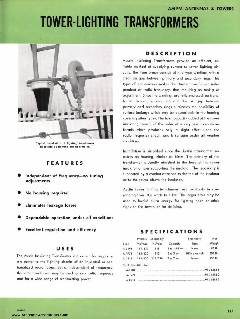
AM-FM ANTENNAS & TOWERS
TOWER-LIGHTING TRANSFORMERS
Typica l insta llation of lighting transfo rmer to isolate ac lighting circu it from rf.
FEATURES
• Independent of frequency- no tuning adjustments
• No housing required
• Eliminates leakage losses
• Dependable operation under all conditions
• Excellent regulation and efficiency
USES The Austin Insulating Transformer is a device for supplying
a-c power to the lighting circuits of an insulated or sec
tiona lized radio tower. Being independent of frequency,
the sa me transformer may be used for any radio frequency
a nd for a wide range of transmitting power.
8.6760
DESCRIPTION Austin Insulating Transformers provide an efficient, re
lia b le method of supplying current to tower lighting cir
cuits. The transformer consists of ring type windings with a
clear air gap between primary and secondary rings. This
type of construction makes the Austin transformer inde
pendent of radio frequency, thus req uiring no tuning or
a d justment. Since the windings are fully enclosed, no trans
former housing is required, and the air gap betwee:1
primary and secondary rings eliminates the possibility of
surface leakage which may be appreciable in the housing
covering other types. The total capa city added at the tower
insulating zone is of the order of a very few micro-micro
farads which produces on ly a slig ht effect upon the
radio fre q uency circuit, and is constant under all weather
cond itions.
Insta llation is simplified since the Austin transformer re
q uires no housing, chokes or filters. The primary of the
transformer is usually attached to the base of the tower
insu lator or pier supporting the insulator. The secondary is
supported by a cond uit attached to the top of the insulator
or to the tower a bove the insulator.
Austin tower-lighting transformers are availa ble in sizes
ranging from 700 watts to 7 kw. The larger sizes may be
used to furnish extra energy for lighting neon or other
signs on the tower, or for de-icing.
SPECIFICATIONS Primary Secondary Secondary Net
Type Voltage Voltage Capacity Taps Weight
A•2101 115/230 115 1 to 1.75 kv. None 85 lbs.
A-1971 115/230 115 2 to 3 kv. 10% over volt. 201 lbs.
A·2815 115/230 115/230 3 to 7 kv. None 300 lbs.
Stock Identification :
A-2101 ................. .... .. ...... ....................................................... MJ.28215•1
A•l971 .......................................... .......................................... MJ .28215·2
A•2815 ..... ................................................ ........ ..... ............... ... MJ .28215•3
117 www.SteamPoweredRadio.Com

AM-FM ANTENNAS & TOWERS
118
ANTENNA LIGHTING CHOKE COILS
View showing Ml-7112-C Antenna Lighting Choke Coi l mounted above isolation coil in w eatherproof housing . RCA Type BPA Anten na Tuning Units have provisions for mounting chokes in same housing.
DESCRIPTION In broadcast transmitter installations where the towe r itself forms the a ntenna , special transformers or radio-frequency choke coils must be employed to feed power to the lighting circuits on the tower. The Ml -7112-C Double Winding
Choke Coil and Ml -27726 Triple Winding Choke Coil have been designed for th is purpose. Their electrical characteristics are such that they present a low impedance to commercial lighting frequencies and a high impedance to radio frequencies in the broadcast range . They, therefore, provide a means for supplying e nergy to the tower lighting circuits and at the same time prevent any appreciable loss of r-f energy supplied to the tower by the rad io transmitter.
The coils consist of double or triple windings on a bakelite form, coated with an insulating varnish which binds the turns toge ther and prevents moisture absorption. The coils must be protected from weather by installing them with in some weatherproof enclosure. All windings that are not directly connected to the tower or ground should be properly bypassed by suitable capacitors.
SPECIFICATIONS Maximum Continuous Curren t (50 / 60 cycles)
D-C Resistance (each winding) .......... .
Inductance at 1 me .....
Le ngt h ...... .
.............. 15 amperes
Approx . 0.15 ohms
360 microhenries
. ...... 11 !¥8"
Diameter ......... ...... ... .......................... . ..... •··-······ ·························· · ·••· 4 "
Stock Ide ntification :
Choke Coil, Double W inding ..... .
Choke Coil, Trip le Win ding
Accessories Capacitors .01 MFD ....... .
Weatherproof Housing ........ .
Ml-7112-C
MJ .27726
. .... Ml -27728-1
. ...... Ml -27741
Typica l Antenna Tower Lighti ng System diagrams and close-up view of Choke Coil , Ml-7112-C.
SINGLE Cl RCU IT 11-Ml-7112 - C i
RF CONNECTION
:11ov.: ~ IOR2 = KVA
~ PO WER SUP PLY
3 Cl RCU ITS TRA NSFER RE LAY AT
LOWER BASE 4 WIRE DISTRIBUTION
(2 -MI-7112-Cl
SE RIES RELAY
I I I I 1 110v. 1
~ IOR2
~ KVA I I IOV I
POWER SUPPLY
2 Cl RC UITS
2 CIRCUITS
TOP LIG HT & FL A SHER
AT LO WER BA SE 3 WIRE DISTRIBUTION
11- MI -2772 6)
I I I I I I IOV I
RF CON NECTI ON
'\ INSULATORS
~ IOR2
~ KVA
PO WER SUPPLY
3 WIRE DISTRI BUTION
(I- Ml - 27726 )
RF CONNECTION
' ' I I I IIOV. I
IQQOOO) I OR 2 ~ KVA 11,ov.l
POWER SUPPLY
B.6760
www.SteamPoweredRadio.Com
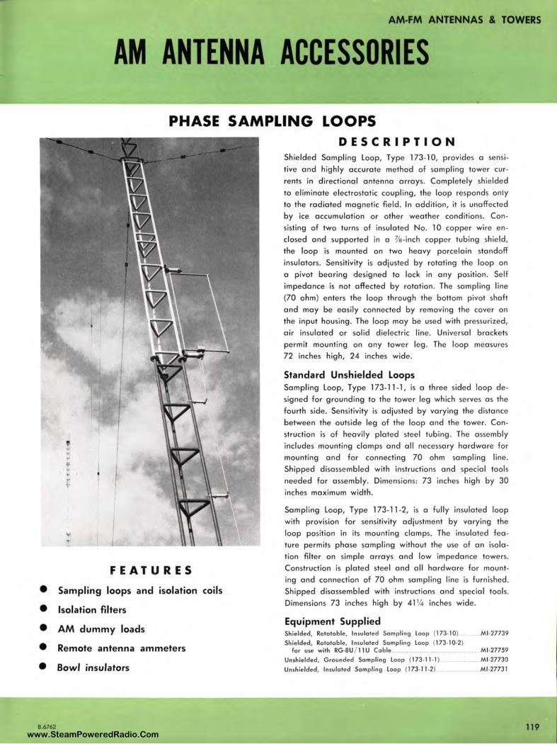
AM-FM ANTENNAS & TOWERS
AM ANTENNA ACCESSORIES
PHASE SAMPLING LOOPS
f , . . y ..
FEATURES
• Sampling loops and isolation coils
• Isolation filters
• AM dummy loads
• Remote antenna ammeters
• Bowl insulators
B.6762
DESCRIPTION Shielded Sampling Loop, Type 173-10, provides a sensi
tive and highly accurate method of sampling tower cur
rents in directional antenna arrays. Completely shielded
to eliminate electrostatic coupling, the loop responds only
to the radiated magnetic field. In addition, it is unaffected
by ice accum ulation or other weather conditions. Con
sisting of two turns of insulated No. 10 copper wire en
closed a nd supported in a 3/e-inch coppe r tubing shield,
the loop is mounted on two heavy porcelain standoff
insulators. Sensitivity is adjusted by rotating the loop on
a pivot bearing designed to lock in any position . Self
im pedance is not affected by rotation. The sampling line
(70 oh m) enters the loop through the bottom pivot shaft
and may be easily connected by removing the cover on
the input housing . The loop may be used with pressurized ,
air insulated or solid dielectric line . Universal brackets
permit mounting on any tower leg . The loop measures
72 inches high, 24 inches wide .
Standard Unshielded Loops Sampling Loop, Type 173-11-1, is a three sided loop de
signed for grounding to the tower leg which serves as the
fourth side. Sensitivity is adjusted by varying the distance
between the outside leg of the loop and the tower. Con
struction is of heavily plated steel tubing. The assembly
includes mounting clamps and all necessary hardware for
mounting and for connecting 70 ohm sampling line.
Shipped disassembled with instructions and special tools
needed for assembly. Dimensions: 73 inches high by 30
inches maximum width.
Sampling Loop, Type 173-11 -2, is a fully insulated loop
with provision for sensitivity adjustment by varying the
loop position in its mounting clamps. The insulated fea
ture permits phase sampling without the use of an isola
tion filter on simple arrays and low impedance towers.
Construction is plated steel and all hardware for mount
ing and connection of 70 ohm sampling line is furnished .
Shipped disassembled with instructions and special tools.
Dimensions 73 inches high by 41 ¼ inches wide.
Equipment Supplied Shielded , Rototoble, Insulated Sampling loop (173-10) ... Ml -27739
Shielded, Rotatoble, Insulated Sampling loop (173-10-2) for use with RG-SU / 11 U Cable .............................. ... ... . .... Ml -277S9
Unshielded , Grounded Sampl ing loop (173-11 -1)... . ............ Ml -27730
Unshielded, Insulated Sampling loop (173-11 -2) ....................... Ml -27731
119 www.SteamPoweredRadio.Com
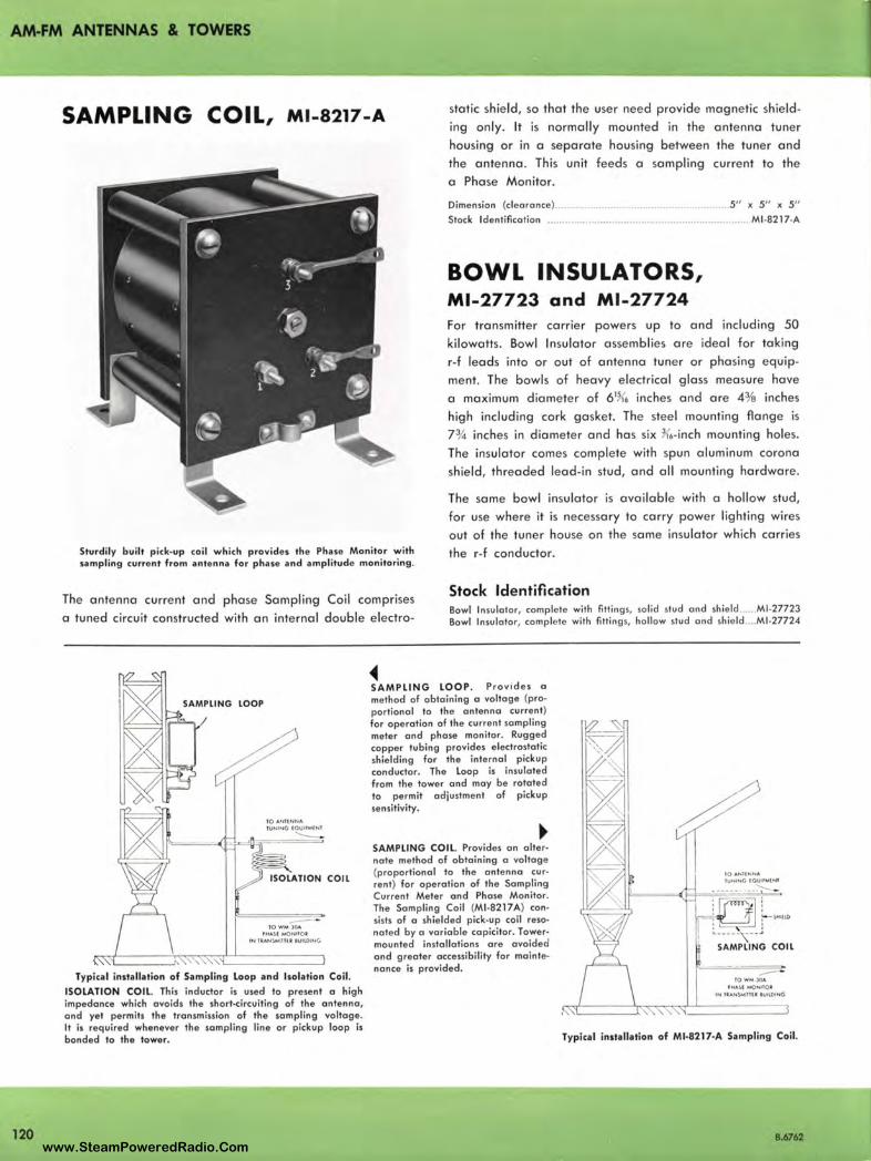
AM-FM ANTENNAS & TOWERS
120
SAMPLING COIL, Ml-8217-A static shield, so that the user need provide magnetic shield
ing only. It is normally mounted in the antenna tuner
housing or in a separate housing between the tuner and
the antenna . This unit feeds a sampling current to the
a Phase Mon itor.
Dimension (clearance)..... .... ..... ....... ... ............. . ... . 5" x 5" x 5"
Stock Identification ................. ........................................... ..... Ml -8217-A
BOWL INSULATORS, Ml-27723 and Ml-27724 For transmitter carrier powers up to and including 50
kilowatts. Bowl Insulator assemblies are ideal for taking
r-f leads into or out of antenna tuner or phasing equip
ment. The bowls of heavy electrical glass measure have
a maximum diameter of 61K6 inches and are 43/a inches
high including cork gasket. The steel mounting flange is
7¾ inches in diameter and has six 3<6- inch mounting holes.
The insulator comes complete with spun aluminum corona
shield, threaded lead-in stud, and all mounting hardware .
Sturdi ly built pick-up coil which provides th e Phase Monitor with sampling current from antenna for phase and amplitude monitoring .
The same bowl insulator is available with a hollow stud,
for use where it is necessary to carry power lighting wires
out of the tuner house on the same insulator which carries
the r-f conductor.
The antenna current and phase Sampling Coil comprises
a tuned circuit constructed with an internal double electro-
Stock Identification Bowl ln su lotor, complete with fittings, solid stud ond shield .. Ml-27723 Bowl lnsulo tor, complete with fittings, hollow stud and shie ld .... Ml -27724
- · 10WM J04 PHASI MONIIOI
IN tlA.N$Mlllll IUllOING
Typical installation of Sampling loop and Isolation Coil.
ISOLATION COIL. This inductor is used to present a high impedance which avoids the short-circuiting of the antenna, and yet permits the transmission of the sampling voltage. It is required whenever the sampling line or pickup loop is bonded ta the tower.
• SAMPLING LOOP . Provides a method of obtaining a voltage (pro• portional to the antenna current) for operation of the current sampling meter and phase monitor. Rugged copper tubing provides electrostatic shielding for the internal pickup conductor. The loop is insulated from the tower and may be ratoted to permit adjustment of pickup sensitivity.
• SAMPLING COIL. Provides an alter-nate method of obtaining a voltage (proportional to the antenna current) for operation of the Sampling Current Meter and Phase Monitor. The Sampling Coil (Ml-8217A) consists of a shielded pick-up coil resonated by a variable capicitor. Towermounted installations ore avoided and greater accessibility for maintenance is provided.
SAMPLING COil
--· TO WM JOA PHAU M()NIIOI
IN tlANSMIITU IUllOING
Typical installation of Ml-8217-A Sampling Coil.
B.6762 www.SteamPoweredRadio.Com
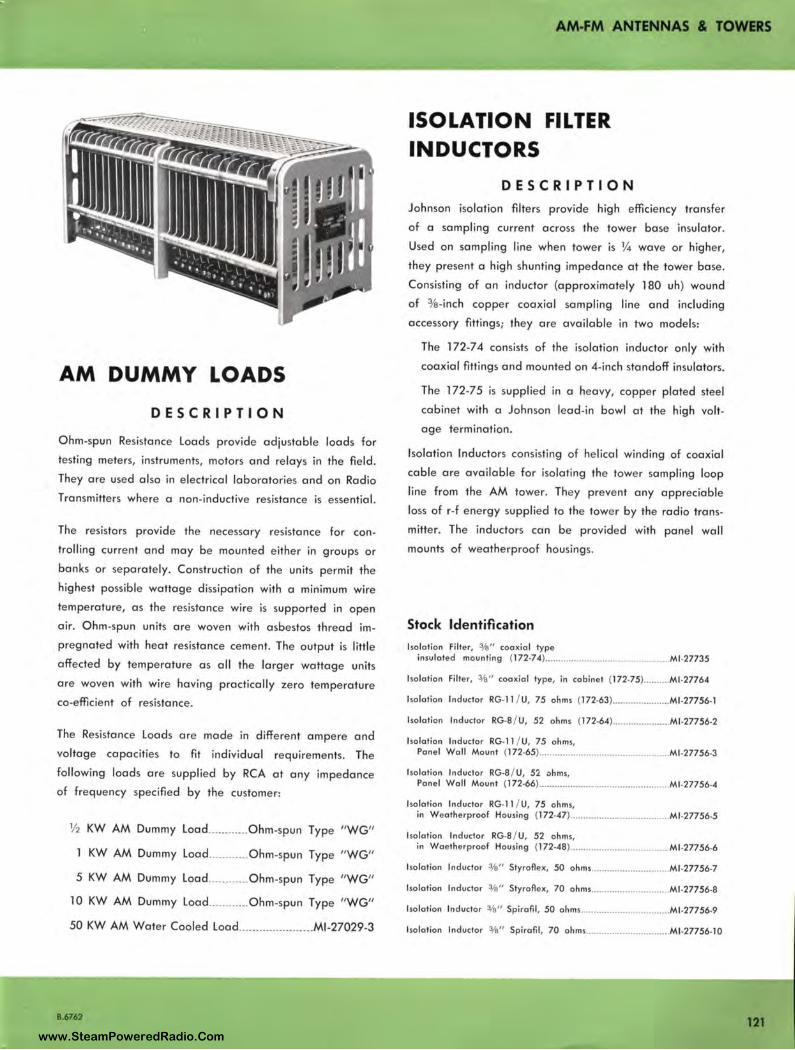
AM DUMMY LOADS
DESCRIPTION
Ohm-sp un Resistance Loads provide adjustable loads for
testing meters, instruments, motors and relays in the field.
They are used also in electrical laboratories and on Radio
Transmitters where a non-inductive resistance is essential.
The resistors provide the necessary resistance for con
trolling current and may be mounte d either in groups or
banks or separately. Construction of the units permit the
highest possible wattage dissi pation with a minimum wire
temperature, as the resistance wire is supported in open
air. Ohm-spun units are woven with asbestos thread im
pregnated with heat resistance cement. The output is little
affected by temperature as all the larger wattage units
are woven with wire having practically zero temperature
co-efficient of resistance.
The Resistance Loads are made in different ampere and
voltage capacities to fit individual requirements. The
following loads are supplied by RCA at any impedance
of frequency specified by the customer:
½ KW AM Dummy Load ... ...... ... Ohm-spun Type "WG"
l KW AM Dummy Load ... ......... Ohm-spun Type "WG"
5 KW AM Dummy Load ............ Ohm•spun Type "WG"
10 KW AM Dummy Load ............ Ohm-spun Type "WG"
50 KW AM Water Cooled Load ...................... Ml -27029-3
B.6762
AM-FM ANTENNAS & TOWERS
ISOLATION FILTER INDUCTORS
DESCRIPTION
Johnson isolation filters provide high efficiency transfer
of a sampling current across the tower base insulator.
Used on sampling line when tower is ¼ wave or higher,
they present a high shunting impedance at the tower base.
Consisting of an inductor (approximately 180 uh) wound
of 3/a-inch copper coaxial sampling line and including
accessory fittings; they are available in two models:
The 172-7 4 consists of the isolation inductor only with
coaxial fittings and mounted on 4-inch standoff insulators.
The 172-75 is supplied in a heavy, copper plated steel
cabinet with a Johnson lead -in bowl at the high volt
age termination.
Isolation Inductors consisting of helical winding of coaxial
cable are available for isolating the towe r sampling loop
line from the AM tower. They preve nt any appreciable
loss of r-f energy supplied to the tower by the radio trans
mitter. The inductors can be provided with panel wall
mounts of weatherproof housings.
Stock Identification lso lotion Filter, % " coaxial type
insulated mounting (l 72•74) ................................................ Ml •27735
Isolation Filter, %" coaxial type, in cabinet (172.75) ..... .... .Ml•27764
Isolation Inductor RG• l l / U, 75 ohms (172•63) ......... .. ......... .. Ml •27756•1
Isolation Inductor RG·B/ U, 52 ohms (l 72•64) .... ....... ........... M1 •27756•2
Iso lation Inductor RG• l l / U, 75 ohms, Pane l Woll Mount (172•65) ................................................. Ml•27756·3
Iso lation Inductor RG·B / U, 52 ohms, Panel Woll Mount (172•66) ... - ............................................. Ml •27756•4
Isolation Inductor RG•l l / U, 75 ohms, in Weatherproof Housing (172•47) ............................. ......... M1 •27756•5
lsolotion Inductor RG·B/ U, 52 ohms, in Woetherproof Housing (172•48) ................. ............ ......... Ml •27756•6
Isolation Ind uctor %" Styroflex, 50 ohms ......... ..... ............... Ml •27756•7
Iso lation Inductor % " Styroflex, 70 ohms .............................. Ml •27756•8
Isolation Inductor %" Spirofi l, 50 ohms .................................. Ml •27756•9
Isolation Inductor % " Spirofil , 70 ahms ................................ Ml.27756•10
121 www.SteamPoweredRadio.Com

AM-FM ANTENNAS & TOWERS
REMOTE METERING
DESCRIPTION The BPM-1 series of Remote Metering Kits provides
a means of observing the antenna current at a re
mote location (transmitter house). Basically the unit
is an electroslatically shielded current transformer
with an adjustable loop primary coil and a tapped
secondary coil in series with a gemanium crystal and
loading resistor. The laps provided on the secondary
coil and the adjustable coupling between that coil
and the primary loop provide coarse and vernier
control of the remote meter indication. A wide range
of antenna currents (approximately 1 ampere to 30
amperes) can be metered depending on the operat
ing frequency. The unit has been designed for in
stallation in antenna tuner housings employed with
transmitter of 50 kw or less, depending on the volt
age and displacement between the primary circuit
and grounded Faraday shield.
The kit is intended to be used with Ml-28037-A,
Ml -28037-B, Ml -28073 or Ml -27644 Remote Am
meters; the meter of the two first series is a 3" rec
tangular cased meter while the latter series is a 4"
rectangular cased meter. These meters have a 1 ma
d-c movement, and are available in various scale
ranges lo match the scale of the antenna ammeter .
When ordering, specify desi red meter scale.
KITS , BPM - 1B , l C, 1D
Tili' I ' .... ·· .·. ·· .. ·· ..· , ,
Ii' .. '' I.· r .. · .. ·.·.,.··.·1j•,1 .. , ... · .. \.·. I ·, !II ',, i t t ·~ 1 I , • ;
, ~,, . ••
SPECIFICATIONS REM OTE METER ING KIT
Dimensions ............................................... 7" high , 7 1/a" wide, 51/a" deep Sensitivity:
1-30 Amperes .................................................... ·-····· ............... AI 1600 kc 3-30 Amperes .................. __ .............. At 540 kc
Stock Identification .. ......... .. ............. Ml -28027-A
METER
Dimension ............. ... ........... .. ... ........................ 3" and 4" rectangular case Scole Ronges.. .................. 0-2, 0-3, 0-5, 0-8, 0-10, 0-15, 0-20, 0-30 amps. Sensitivity .. ....................... ........ .. .. .... ...................... -...... 1 ma. d-c movement Stock Identificat ion :
3" White Scale ... .. ......... ..... .... ....... ........................................ Ml-28037-A 3" Black Scale .. .... ... .................... ................................. .. .... .. Ml-28037-B 4" White Scale ...... ... ... ...... ........ ... ........ ....... .. ..................... ... Ml -28037 4" Black Scale ................ .. .................. .. ................................ Ml .27644
R-F METERS
122
Spare R-F Ammeters furnished with an internal or external
thermocouple provide a means of metering antenna base
current and transmitter output line current. The meters
are calibrated for mounting on Va" steel panel or housing
such as the transmitter or antenna tuning unit .
Three series of meters are ava ilable. The Ml -7147 Series
provides a three-i nch , white face meter in rectangular case
with expanded scale ranges of 0-2 lo 0-20 amperes. It
has an internal thermocouple and is designed for use with
the BPA Series of Antenna Tuning Units. The Ml -28048
Meter Series is similar except for black face. It matches
meters provided on the BT A-250M Transmitter. The Ml -
7157 Se ries of R-F Meters have a four-i nch square case,
black face, and expanded scale ranges of 0-2 to 0-25
amperes . Each meter has an external the rmocouple . They
match meters used on the BT A-1 M, 1 R, and BT A-5H/ 1 OH
transmitters.
Stock Identification 3" R-F Meter, 0-2 amp, white face ...... ..... .... .... .... Ml-7147-2
3" R·F Meter, 0.3 amp, wh ite face .............................. Ml -7147-3
3" R-F Meter, 0.5 amp, white face ......
3" R·F M eter, 0·8 amp, white face ....
3" R-F M eter, 0-10 amp, white face ...
3" R-F Meter, 0.15 amp, white face ....
3" R-F Meter, 0-20 amp, white face ....
3" R-F Meter, 0-2 amp, black face ... ..
3" R-F Meter, 0-3 amp, block face ... ..
3" R-F Meler, 0-5 amp, black face .. .
3" R-F Meter, 0·8 amp, black face .... ..
..
...
.. ..
Ml-7147•5
•············· . Ml -7147•8
.. ............ M1 •7147-10
........... Ml-7147•15
.. .................. Ml -7147•20
... Ml-28048•2
.. Ml -28048•3
. Ml•28048-5
3" R-F Meter, 0-10 amp, black face .................. ..
Ml -28048•8
.Ml -28048-10
.... Ml -7157-F2
... Ml •7157-F3
... Ml -7157-F5
4" R-F Mete r, 0-2 amp, black face ..
4" R-F Meter, 0-3 amp, black face ... .
4" R-F Meter, 0-5 amp, black face .. .
4" R-F Meter, 0-8 amp, black face .. .. ... Ml -7157-F8
4" R-F Meter, 0-10 amp, black face ......... ............. .Ml -7157-Fl0
4" R-F Meter, 0-15 amp, black face .......... ...... .. ................ Ml -7157-Fl 5
4" R-F Meter, 0-20 amp, black face ................................... Ml -7157-F20
4" R-F Meter, 0-25 amp, black face ............................... .. .... Ml -7157-F25
B.6762
www.SteamPoweredRadio.Com
wigfi
Stolen 2 Line Transparent
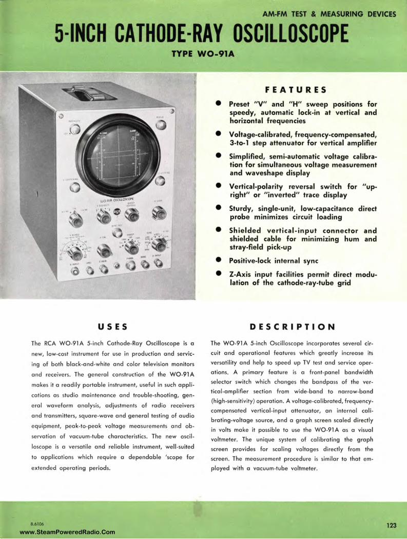
AM-FM TEST & MEASURING DEVICES
5-INCH CATHODE-RAY OSCILLOSCOPE TYPE W0-91A
US ES
The RCA WO-91 A 5-inch Cathode-Ray Oscilloscope is a
new, low-cost instrument for use in production and servic
ing of both black-and-white and color television monitors
and receivers . The general construction of the W0-91 A
makes it a readily portable instrument, useful in such appli
cations as studio maintenance and trouble-shooting, gen
eral waveform analysis, adjustments of radio receivers
and transmitters, square-wave and general testing of audio
equipment, peak-to-peak voltage measurements and ob
servation of vacuum-tube characteristics. The new oscil
loscope is a versatile and reliable instrument, well -suited
to applications which require a dependable 'scope for
extended operating periods.
8.6106
FEATURES
• Preset "V" and "H" sweep positions for speedy, automatic lock-in at vertical and horizontal frequencies
• Voltage-calibrated, frequency-compensated, 3-to-1 step attenuator for vertical amplifier
• Simplified, semi-automatic voltage calibration for simultaneous voltage measurement and waveshape display
• Vertical-polarity reversal switch for "upright" or "inverted" trace display
• Sturdy, single-unit, low-capacitance direct probe minimizes circuit loading
• Shielded vertical - input connector and shielded cable for minimizing hum and stray-field pick-up
• Positive-lock internal sync
• Z-Axis input facilities permit direct modulation of the cathode-ray-tube grid
DESCRIPTION
The WO-91 A 5-inch Oscilloscope incorporates several cir
cuit and operational features which greatly increase its
versatility and help to speed up TV test and service oper
ations. A primary feature is a front-panel bandwidth
selector switch which changes the bandpass of the ver
tical-amplifier section from wide-band to narrow-band
(high-sensitivity) operation. A voltage-calibrated, frequency
compensated vertical-input attenuator, an internal cali
brating-voltage source, and a graph screen scaled directly
in volts make it possible to use the WO-91 A as a visual
voltmeter. The unique system of calibrating the graph
screen provides for scaling voltages directly from the
screen. The measurement procedure is similar to that em
ployed with a vacuum-tube voltmeter.
123 www.SteamPoweredRadio.Com

AM-FM TEST & MEASURING DEVICES
124
DESCRIPTION (Cont'd)
A feature of special value in television work is the pre
setting of the sweep positions to provide automatic lock-in
on vertical - and horizontal -frequency signals. The sweep
frequency control also is contin uously adjustable from l 0
cps to l 00 kc. The sweep oscillator has excellent stability
at high sweep rates, a fast retrace, and adequate linearity
throughout its frequency range. The overall frequency
range cf the oscillator is divided into four basic ranges;
a vernier adjustment, which overlaps the basic sweep
ranges, provides exact adjustment of the sweep frequency.
The amount of sync signal fed to the sweep oscillator may
be adjusted by means of a front-panel control. Sweep
synchronization is exceptionally stable throughout the
sweep range of the oscillator.
A Z-Axis input terminal is provided on the front panel of
the WO-91 A to permit direct modulation of the control
grid of the cathode-ray tube . This is useful in special appli
cations requiring trace blanking and time calibration of the
sweep trace. A control switch is also provided for reversing
the vertical polarity of the trace. By means of this control,
the trace may be displayed in an upright or inverted
position.
To facilitate its use, the oscilloscope is equipped with a
specially designed single-unit probe and input cable. This
WG-300B Direct/ Low-Capacitance Probe and Cable is
provided with a sliding switch in the probe housing which
permits its use in circuits which would not function properly
if loaded down by a conventional oscilloscope. A WG-
302 RF/ IF/ VF Signal Tracing Probe is a useful accessory
for rapid isolation of trouble in r-f, i-f, and video stages.
New Graph Screen with "VTVM"-type scales simplifies voltage measurement. Here's how:
"Zero" base line corresponds to " Zero" on VTVM scales.
Vertical scales are multipurpose; full -scale points correspond to switch settings of "V" range control.
Scales are linear and are subdivided into voltage values.
SPECIFICATIONS
Performance Specifications Frequency Response (reference frequency 10 kc):
Vertical Amplifier:
Wide-Band Positions 10 cps to 4.5 mc ........ ... ........... .... Within ± 1 db
High•Sensitivity Positions 10 cps to 0.5 mc .. ......... ... ...... Within - 1 db
High•Sensitivity Positions 10 cps to 1.5 mc .................... Within - 6 db
Horizontal Amplifier 10 cps to 500 kc ... .. ..... ....... .... .. ... ... . Within - 6 db
Deflection Sensitivity:
Vertical Amplifi er: Wide.Bond Positions
rms p/ p
At V INPUT Connector ........ 0.053 0.15
With WG.3008 set to " DIRECT" ..... ..................... 0.053 0. 15
With WG.3008 set to " LOW CAP" ......... ....... .... 0.53 1.5
High.Sensitivity Positions
rms p/p
0.018 0.05 volt/in
0.018 0.05 volt/in
0.18 0.5 volt/in
Horizontal Amplifier at H INPUT terminal.. ........ ...... 0.15 rms volt / in
Average Rise Time (Vertical Amplifier):
4.5 MC Positions ... ... .... ...... ................................................ ...... ...... 0 .1 µsec
1.5 MC Positions ............................. ...... ........ ...... .. .................... ..... 0 .5 µsec
Maximum A·C Input Voltage (in presence of 600 volts d•c) .. ...... ....... ............. .................................. 600 p/ p volts
Input Resistance and Capacitance:
Vertical Amplifier:
At V INPUT Connector ... .... ...... ....... ...... l megohm shun ted by 40 µµf
With WG.3008 set ta " DIRECT" .. ... ..... 1 megohm sh unted by 75 µµf
With WG•300B set to " LOW CAP" .. 10 meghoms shunted by 11 µµf
HorizQ!ltal Amplifiers (at H INPUT terminal) ................................. ......... 10 megohms shunted by 30 µµf
Sync Input Terminal.. ......... ........ ...... . 0 .5 megohm shunted by 35 µµf
Sweep•Circuit Frequency (variable) .......... ...... ....... ......... 10 to 100,000 cps
Z•Axis In put:
Minimum Input Voltage for Blanking ......................... ........... 12 rms volts
Frequency Response ..... .. ................ ............ ...................... 3 cps to 500 kc
Tube Complement 1- 6AN8
2- 6J6
l - 12AT7
1- 12AU7
l - 12AX7
1- 5Y3.GT
l - 1V2
l - 5UP1
Power Supply ...... ................ .... ......... ........ ......... 105•125 volts, 50/ 60 cycles
Power lnput .............. ................................. ......•................................ 65 watts
Dimensions ...... 13½ " high , 9" wide, 16½" deep Weight ....... . 30 lbs.
Finish ....... ..... .. .. ........ Blue•gray hammeroid case, brushed.aluminum panel
Equipment Supplied 5" Cathode·Ray Oscil loscope ......... .... .................................... ... ...... wo.91 A
Including tubes in place, direct / low•capacitance probe and cable, alligator clip, clip insulator, ground cable, green graph screen, and instruction book.
B.6106
www.SteamPoweredRadio.Com
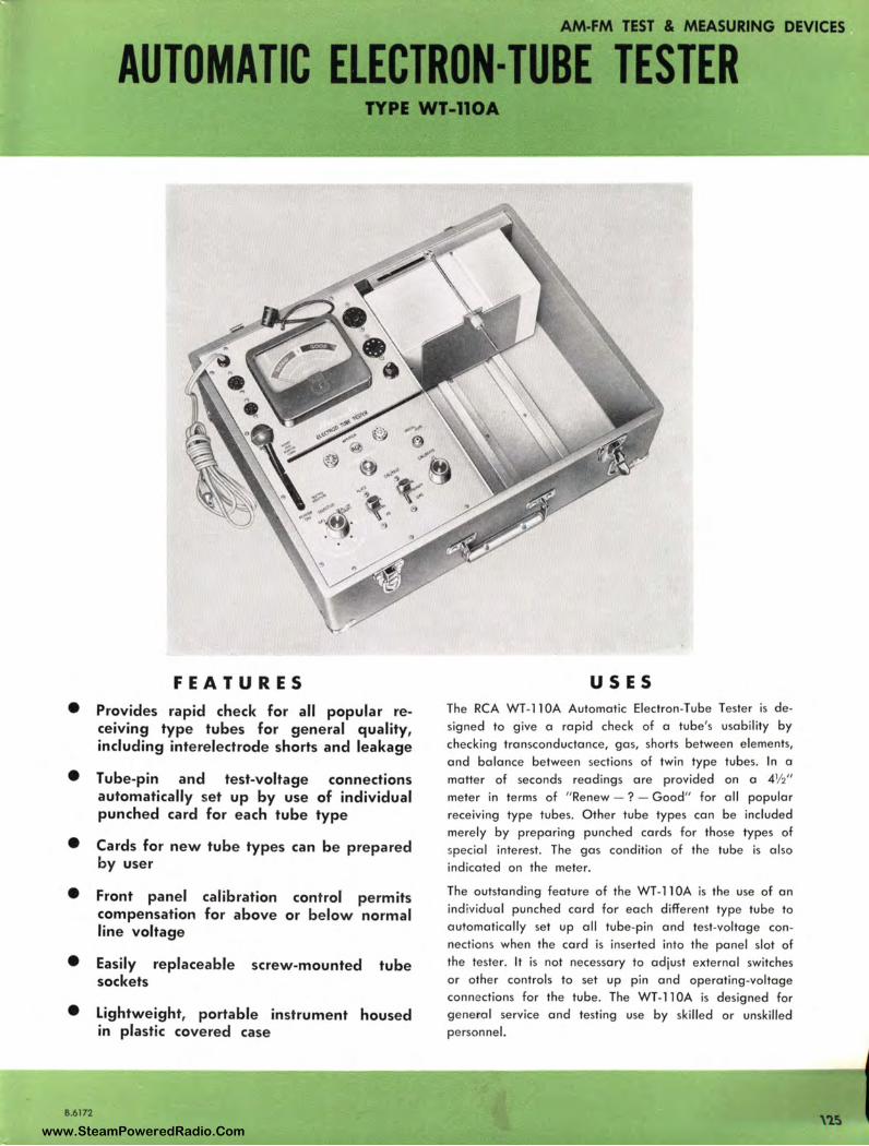
•
•
• •
• •
8.6172
AM-FM TEST & MEASURING DEVICES
AUTOMATIC ELECTRON-TUBE TESTER TYPE WT-110A
FEATURES
Provides rapid check for all popular receiving type tubes for general quality, including interelectrode shorts and leakage
Tube-pin and test-voltage connections automatically set up by use of individual punched card for each tube type
Cards for new tube types can be prepared by user
Front panel compensation line voltage
calibration control permits for above or below normal
Easily replaceable screw-mounted tube sockets
Lightweight, portable instrument housed in plastic covered case
USES The RCA WT-1 l 0A Automatic Electron-Tube Tester is designed to give a rapid check of a tube's usability by checking transconductance, gas, shorts between elements, and balance between sections of twin type tubes. In a matter of seconds readings are provided on a 4½" meter in terms of " Renew - ? - Good" for all popular receiving type tubes. Other tube types can be included merely by preparing punched cards for those types of special interest. The gas condition of the tube is also indicated on the meter.
The outstanding feature of the WT-1 l 0A is the use of an ind ividual punched card for each different type tube to automatically set up all tube-pin and test-voltage connections when the card is inserted into the panel slot of the tester. It is not necessary to adjust external switches or other controls to set up pin and operating-voltage connections for the tube. The WT-11 0A is designed for ge neral service and testing use by skilled or unskilled personnel.
www.SteamPoweredRadio.Com
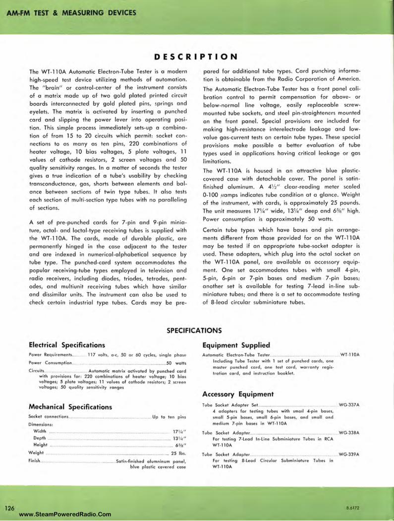
AM-FM TEST & MEASURING DEVICES
126
DESCRIPTION
The WT-11 0A Automatic Electron-Tube Tester is a modern
high-speed test device utilizing methods of automation .
The "brain" or control -center of the instrument consists
of a matrix made up of two gold plated printed circuit
boards interconnected by gold plated pins, ~prings and
eyelets. The matrix is activated by inserting a punched
card and slipping the power lever into operating posi
tion. This simple process immediately sets-up a combina
tion of from 15 to 20 circuits which permit: socket con
nections to as many as ten pins, 220 combinations of
heater voltage, 10 bias voltages, 5 plate voltages, 11
val ues of cathode resistors, 2 screen voltages and 50
quality sensitivity ranges. In a matter of seconds the tester
gives a true indication of a tube's usability by checking
transconductance, gas, shorts between elements and bal
ance between sections of twin type tubes. It also tests
each section of multi-section type tubes with no paralleling
of sections.
A set of pre-punched cards for 7-pin and 9-pin minia
ture, octal- and loctal -type receiving tubes is supplied with
the WT-11 0A. The cards, made of durable plastic, are
permanently hinged in the case adjacent to the tester
and are indexed in numerical -alphabetical sequence by
tube type. The punched-card system accommodates the
popular receiving-tube types employed in television and
radio receivers, including diodes, triodes, tetrodes, pent
odes, and multiunit receiving tubes which have similar
and dissimilar units. The instrument can also be used to
check certain industrial type tubes. Cards may be pre-
pared for additional tube types. Card punching informa
tion is obtainable from the Radio Corporation of America.
The Automatic Electron-Tube Tester has a front panel cali
bration control to permit compensation for above- or
below-normal line voltage, easily replaceable screw
mounted tube sockets, and steel pin-straighteners mounted
on the front panel. Special provisions are included for
making high-resistance interelectrode leakage and low
value gas-current tests on certain tube types. These special
provisions make possible a better evaluation of tube
types used in applications having critical leakage or gas
limitations.
The WT-11 OA is housed in an attractive blue plastic
covered case with detachable cover. The panel is satin
finished aluminum. A 4½" clear-reading meter scaled
0-100 pomps indicates tube condition at a glance. Weight
of the instrument, with cards, is approximately 25 pounds.
The unit measures 17¼" wide, 13¼" deep and 65/a" high .
Power consumption is approximately 50 watts.
Certain tube types which have bases and pin arrange
ments different from those provided for on the WT-11 0A
may be tested if an appropriate tube-socket adapter is
used. These adapters, which plug into the octal socket on
the WT-11 0A panel, are available as accessory equip
ment. O ne set accommodates tubes with small 4-pin,
5-pin, 6-pin or 7-pin bases and medium 7-pin bases;
another set is available for testing 7-lead in-line sub
miniature tubes; and there is a set to accommodate testing
of 8-lead circular subminiature tubes.
SPECIFICATIONS
Electrical Specifications Power Requ irements........ 117 volts, o-c, 50 or 60 cycles, single phase
Power Consumption ............. ..................................................... ...... 50 watts
Circuits ........................... ...... Automatic matrix activated by punched cord with provisions for: 220 combinations of heater voltage; 10 bias voltages; 5 plate voltages; 11 values of cathode resistors; 2 screen voltages; 50 quality sensitivity ranges
Mechanical Specifications Socket connections .............................................................. Up to ten pins
Dimensions:
Width .... . ... ............... ....•................................................. ... ... 17¼"
Depth ............................................................................................. 13¼ "
Height ...................................... .. .... .................................................. 6 % "
Weight ....... ..... . . ............................. ... ..... ................................... . 25 lbs.
Finish ...................................................... Satin-finished olumninum panel, blue plastic covered case
Equipment Supplied Automatic Electron-Tube Tesler .. ...... .. .... .... ................................... WT-1 l0A
Including Tube Tester with 1 set of punched cords, one
master punched card, one test cord, warranty regis-
tration cord , and instruction booklet.
Accessory Equipment Tube Socket Adopter Set.................. .............................. WG.J37A
4 adopters for testing tubes with smal l 4-pin bases, small 5-pin bases, small 6-pin bases, and small and
medium 7-pin bases in WT-1 l0A
Tube Socket Adopter .............. .. .................... .. ..... ..... ................. WG-338A
For testing 7-Leod In-Line Subminioture Tubes in RCA WT-ll0A
Tube Socket Adopter ...................................................... . For testing 8-Leod Circular Subminioture Tubes in
WT-ll0A
WG-339A
B.6172
www.SteamPoweredRadio.Com
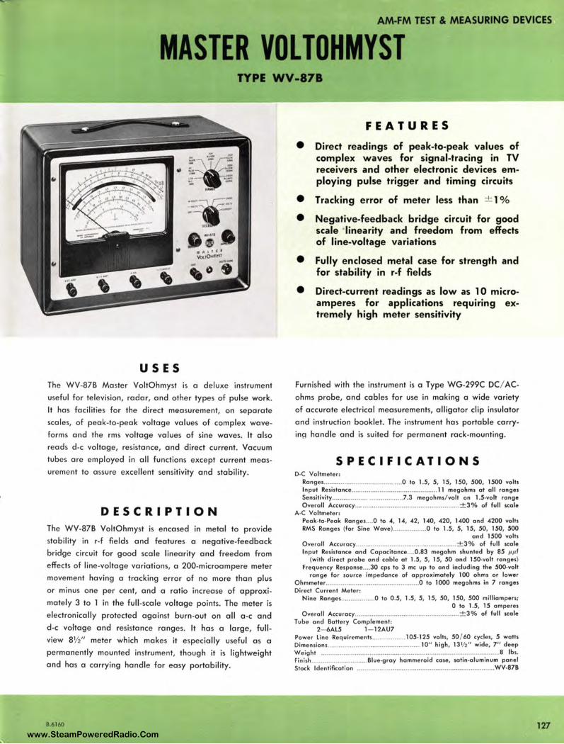
AM-FM TEST & MEASURING DEVICES
MASTER VOL TOHMYST TYPE WV-87B
USES The WV-878 Master VoltOhmyst is a deluxe instrument
useful for television, radar, and other types of pulse work.
It has facilities for the direct mfi!asurement, on separate
scales, of peak-to-peak voltage values of complex wave
forms and the rms voltage values of sine waves. It also
reads d-c voltage, resistance, and direct current. Vacuum
tubes are employed in all functions except current meas
ure ment to assure excellent sensitivity and stability.
DESCRIPTION The WV-878 VoltOhmyst is encased in metal to provide
stability in r-f fields and features a negative-feedback
bridge circuit for good scale linearity and freedom from
effects of line-voltage variations, a 200-microampere meter
movement having a tracking error of no more than plus
or minus one per cent, and a ratio increase of approxi
mately 3 to l in the full -scale vo ltage points. The meter is
electronically protected against burn-out on all a-c and
d-c voltage and resistance ranges. It has a large, full
view 8½ " meter which makes it especially useful as a
permanently mounted instrument, though it is lightweight
and has a carrying handle for easy portability.
B.6160
FEATURES
• Direct readings of peak-to-peak values of complex waves for signal-tracing in TV receivers and other electronic devices employing pulse trigger and timing circuits
• Tracking error of meter less than ± 1 %
• Negative-feedback bridge circuit for good scale ·linearity and freedom from effects of line-voltage variations
• Fully enclosed metal case for strength and for stability in r-f fields
• Direct-current readings as low as 10 microamperes for applications requmng extremely high meter sensitivity
Furnished with the instrument is a Type WG-299C DC/ AC
ohms probe, and cables for use in making a wide variety
of accurate electrical measurements, alligator clip insulator
and instruction booklet. The instrument ha s porta ble carry
ing handle and is suited for permanent rack-mounting.
SPECIFICATIONS D-C Voltmeter:
Ronges ....... ·-··· ·········· ··········· ···· .... 0 to 1.5, 5, 15, 150, 500, 1500 volts Input "esistonce ......... _ .................. -.... ...... ....... 11 megohms at oil ranges Sensitivity .................................... .7 .3 megohms/ volt on 1.5-volt range Overall Accurocy .. _ .. _ .......................... .......... ............. ± 3% of full scale
A-C Voltmeter : Peak-to-Peak Ronges.. .. O to 4, 14, 42, 140, 420, 1400 and 4200 volts RMS Ranges (for Sine Wove) .................. O to 1.5, 5, 15, 50, 150, 500
and 1500 volts Overall Accurocy ...................................................... ± 3% of full scale Input Resistance and Copacitonce .... 0 .83 megohm shunted by 85 µ.µf
(with direct probe and coble at 1.5, 5, 15, 50 and 150-volt ranges) Frequency Response._ .. 30 cps to 3 me up to ond including the 500-volt
range for source impedance of approximately 100 ohms or lower Ohmmeter .................................................. O to 1000 megohms in 7 ranges Direct Current Meter :
Nine Ranges.. ................ O to 0 .5, 1.5, 5, 15, 50, 150, 500 milliampers; 0 to 1.5, 15 amperes
Overall Accu rocy ...... ........ .... ........ .............. ................ ± 3% of full scale Tube and Battery Complement:
2- 6Al5 1- 12AU7 Power line Requirements.. ................ 105-125 volts, 50 / 60 cycles, 5 watts Dimensions.. ................................................ 10" high, 13½ " wide, 7" deep Weight ........... ..... .................. ..... ..... ... .. .. ................. ............................ 8 lbs. Finish ...... ........................ Blue•gray hammeroid case, satin•aluminum panel Stock Identification ............ .. .................. .. .. .. ... ... ..... .. ... .. .. .. .. ... ........ . WV-878
127 www.SteamPoweredRadio.Com
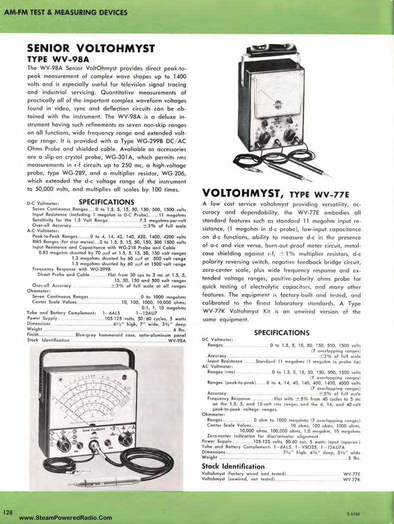
AM-FM TEST & MEASURING DEVICES
128
SENIOR VOLTOHMYST TYPE WV- 98A The WV-98A Senior VoltOhmyst provides direct peak-topeak measurement of complex wave sha pes up to 1400 volts and is especially useful for television signal tracing and industrial servicing. Quantitative measurements of practically all of the important complex waveform voltages found in video, sync and deflection circuits can be obtained with the instrument. The WV-98A is a deluxe instrument having such refinements as seven non-skip ranges on all functions, wide frequency range and extended voltage range. It is provided with a Type WG-299B DC/ AC Ohms Probe and shielded cable. Avaliable as accessories are a slip-on crystal probe, WG-301 A, which permits rms measurements in r-f circuits up to 250 me, a high-voltage probe, type WG-289, and a multiplier resistor, WG-206, which extended the d-c voltage range of the instrument to 50,000 volts, and multiplies all scales by 100 times.
D-C Voltmeter : SPECIFICATIONS Seven Continuous Ranges ...... O lo 1.5, 5, 15, 50, 150, 500, 1500 volts Input Resislonce (including 1 megohm in D·C Probe ) ........ 11 megohms Sensitivity for the 1.5 Volt Ronge ......... .... .. ........ .7 .3 megohms-per-volt Over-all Accuracy ................................... ............ .. ..... ± 3 % of full scale
A·C Voltmete r: Peak-to-Peak Rang es .......... O to 4, 14, 42, 140, 420, 1400, 4200 volts RMS Ranges (for sine waves) .... O lo 1.5, 5, 15, 50, 150, 500 1500 volts Input Resistance and Capacitance with WG.218 Probe and Cable
0.83 megohm shunted by 70 µµf al 1.5, 5, 15, 50, 150 volt ranges 1.3 megohms shunted by 60 µµf al 500 volt range 1.5 megohms shunted by 60 µµf al 1500 volt range
Frequency Response with WG-299B Direct Probe and Cable .............. Flat from 30 cps lo 3 me al 1.5, 5,
15, 50, 150 and 500 volt ranges Over-all Accu racy ............................ ± 3 % of full scale al all ranges
Ohmmete r: Seven Continuous Ranges ...................... .. ................ O to 1000 megohms Cente r Scale Values .................................. 10, 100, 1000, 10,000 ohms;
0 .1, 1, 10 megohms Tube and Battery Complement : 1- 6Al5 1- 12AU7 Pawer Sup pl y ................................ 105•125 volts, 50 / 60 cycles, 5 walls Dimensions ............ ..... ......... ...................... 6 ½ " high, 7" wide, 3¾" deep Weight .. .......................................................... .. ............... .. .................. . 6 lbs. fini sh ................ ........... Blue-g ray hammeroid case, satin•aluminum panel Stock Identification ......................... ... ............................................ WV.98A
VOLTOHMYST, TYPE WV-77E A low cost service voltohmyst providing ve rsatility, accuracy and dependability, the WV-77E embodies all standard features such as standard 11 megohm input resistance, (l megohm in d-c probe ), low-input capacitance on d-c functions, ability to measure d-c in the presence of a -c and vice versa, burn-out proof meter circuit, metalcase shielding against r-f, ± l % multiplie r resistors, d-c polarity reversing switch, negative fee dback bridge circuit, zero-center scale, plus wide frequ e ncy response and extended voltage ranges, positive-polarity ohms probe for quick testing of electrolytic capacito rs, and many othe r features . The equipment is factory -bu ilt and tested, and calibrated to the fin est laboratory standards. A Type WV-77K Voltohmyst Kit is an unwired version of the same equipment.
SPECIFICATIONS DC Voltme ter:
Rang es.. . 0 to 1.5, 5, 15, 50, 150, 500, 1500 volts (7 ovc rlopping ranges)
Accu rocy.............. .. ............ .. ± 3 % of full sco le Input Resistance ....... Standard 11 megohms (1 megoh m in pro be tip)
AC Voltmeter : Rang es (rms).... ..... 0 to 1.5, 5, 15, 50, 150, 500, 1500 vo lts
(7 ove rl app in g ra nges) Ranges (pe ak-to•peak ) 0 ta 4, 14, 40, 140, 400 , 1400 , 4000 volts
(7 overlapping ranges) Accuracy............................... .. .............. .......... .... ± 5 % of full scale Frequ ency Res ponse . . . .. Flat with ± 5 % from 40 cycles to 5 me
on th e 1.5, 5, and 15•vo lt rms ra ng es a nd the 4, 14, and 40•volt peak-to•peak voltage ranges.
Ohmmete r: Rang es ........................ O ohm lo 1000 megohms (7 ove rla pping ra nges) Cente r Scale Volues....... 10 ohms, 100 ohms, 1000 o hms,
10,000 ohms, 100,000 oh ms, 1.0 megoh m, 10 mego hms Zero•center indicat ion for discri minator al ignment
Power Supply ...... .......... 105-125 volts, 50.60 cps, 5 watts input (a pprox.) Tube and Batte ry Comple men t: 1- 6Al5, 1- VSO35, 1- 12AU7A Dimensions.................. ......... .. ... .. 7¾" high , 4¾" dee p, 5%" wide Weight ........................................... ......... .. ... .. ........ ........ . 5 lbs.
Stock Identification Voltohmyst (factory wired and tested) Voltohmysl (unwired, not tested ) ......... .
WV-77E WV-77K
B.6160 www.SteamPoweredRadio.Com

AM-FM TEST & MEASURING DEVICES
FIELD INTENSITY METER TYPE WX-2D
FEATURES
• Truly portable-weight, approximately
12½ lbs. including batteries- size ap
proximately 12" x 8½" x 5½"
• Reads directly in microvolts per meter
- no correction factor charts are needed
• Stable in operation- calibrates readily
in presence of strong fields
• Wide sensitivity range-10 microvolts/
meter to 10 volts / meter
• Accurate- built-in calibrating oscillator
USES The type WX-20 Intensity Meter is a small, accurate and truly portable instrument, especially adapted for field use by Broadcast Station Engineers and Consultants. Designed for battery operation, it provides for a wide range of measurement (10 ftV / meter to l O v / meter) in conducting broadcast band (540 to 1600 kc) field intensity surveys. It makes possible close-in measurements on high-powered directional arrays, as well as interference studies where very low signal strengths are encountered.
D E S C RIPTION The Type WX-20 Field Intensity Meter is direct reading in microvolts per meter without the aid or necessity of charts, curves, correction factors, or computations of any kind . In the WX-20, a statically shielded, unbalanced loop is used as an integral part of the instrument cover. The loop has only a few turns, thus the natural resonant frequency is very much higher than the highest frequency in the operating range. The high side of the loop is loaded with
8.626"
a high "Q" coil to provide the total inductance required
for the operating range. Injection of the calibrating volt
age into the loop circuit is by means of a small toroidal
wound inductance. The " Q" of the loop circuit is approxi
mately l 00 at one megacycle. This high "Q", plus the use
of a stage of radio frequency amplification, results in a
very high order of image rejection. This feature is desir
able since the large increase in the number of stations in
some localities has made impractical the use of field inten
sity meters having insufficient front-end selectivity. By care
ful design, other spurious responses, such as i-f harmonics,
ha:,-e been greatly reduced. The use of crystal diodes for
metering purposes eliminates the meter errors due to vary
ing cathode voltages on thermionic rectifiers. The crystals
are used in special circuits which swamp out variations
due to temperature, etc. The meter will indicate accurately
with filament voltages as low as one volt and plate volt
ages as low as 45 volts.
129 www.SteamPoweredRadio.Com

AM-FM TEST & MEASURING DEVICES
130
Ordinary flashlight cells, obtainable everywhere, are used for the filament. A 67-volt battery of the size in common use in small camera-type radios is used for plate supply. The total plate drain of the receiver is 8 ma. The filament drain is 300 ma. Separate batteries are used for the calibrating oscillator. All batteries are carried in a compartment accessible through a door in the rear of the instrument. Provision is made for checking battery voltages with the same meter as used for field intensity indication.
All tubes are quick-heating filamentary types so that the WX-20 stabilizes within a few seconds, thus it is not necessary to keep the instrument operating between readings. The direct reading feature of the WX-20 simplifies field intensity measurements and eliminates the needs of the usual attenuator readings, meter readings and multiplication factors. A wide sensitivity range, l O volts per meter to l 0 microvolts per meter, permits maximum flexibility of operation within the range of 540 to 1600 kc.
Despite its small size and compactness, nothing has been sacrificed in the way of quality or workmanship. Com-
ponents of the highest quality are used throughout. The design is such that all components are accessible. Broadcast Station Engineers and Consultants will find that it offers extreme flexibility in use and fills a long-felt need for a light-weight, portable instrument.
SPECIFICATIONS Performance Specifications Frequency Range ............ ........................ ................ .............. ... ... 540-1600 kc Sensitivity ................. ...... ................ ... .. 10 µ vi m ta 10 v/ m (all frequencies) Power Supply
(not supplied with equipment) .............. 2 67 ½ VB- 5 1 ½ unit cells (RCA VS016)-(RCA VS00l )
Antenna ................ .................... ........ Built in loop with electro-static shield Dimensions ............................................... ... 9" high , 13" wide, 53/4" deep Weight ................................................................ ........................... 12.6 lbs.
Tube Complement 4- 1T4 2- 1R5
Equipment Supplied WX-2D Field Intensity Meter ..................................................... Ml -30002-D
(Including e lectron tubes in place, Instruction Book 18-4002-4 and Instruction Book Addenda IB-4002-4A)
Accessory Equipment Type 121 Recording Amplifier
Block diagram, Field Intensity Meter, Type WX-2D.
ATTENUATION
LOOP R-F SI
AMPLIFIER
VT-I
1 T4
X-1 METERING CRYSTAL
CALIBRATING OSCILLATOR _ ___,.___
VT-6 IR5
osc. MIXER
VT-2 1R5
GAIN
1-f R2 ~-F AMPLIFIER AMPLIFIER _......__
VT-3 1T4
VT-4
1T4
1-F AMPLIFIER
VT-5 1T4
S2 X-2
LOG. METERING CRYSTAL
METER
B.6264 www.SteamPoweredRadio.Com
wigfi
Stolen 2 Line Transparent
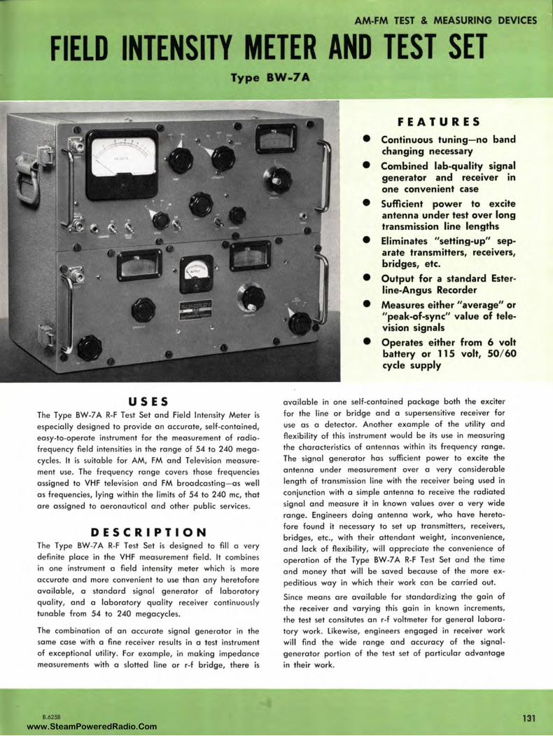
AM-FM TEST & MEASURING DEVICES
FIELD INTENSITY METER AND TEST SET Type BW-7A
USES The Type BW-7 A R-F Test Set and Field Intensity Meter is especially designed to provide an accurate, self-contained, easy-to-operate instrument for the measurement of radiofrequency field intensities in the range of 54 to 240 megacycles. It is suitable for AM, FM and Television measurement use. The frequency range covers those frequencies assigned to VHF television and FM broadcasting- as well as frequencies, lying within the limits of 54 to 240 me, that are assigned to aeronautical and other public services.
DESCRIPTION The Type BW-7A R-F Test Set is designed to fill a ve ry definite place in the VHF measurement field . It combines in one instrument a field intensity meter which is more accurate and more convenient to use than any heretofore available, a standard signal generator of laboratory quality, and a laboratory quality receiver continuously tunable from 54 to 240 megacycles.
The combination of an accurate signal generator in the same case with a fine receiver results in a test instrument of exceptional utility. For example, in making impedance measurements with a slotted line or r-f bridge, there is
B.6258
FEATURES
• Continuous tuning- no band changing necessary
• Combined lab-quality signal generator and receiver in one convenient case
• Sufficient power to excite antenna under test over long transmission line lengths
• Eliminates "setting-up" separate transmitters, receivers, bridges, etc.
• Output for a standard Esterline-Angus Recorder
• Measures either "average" or "peak-of-sync" value of television signals
• Operates either from 6 volt battery or 115 volt, 50/ 60 cycle supply
available in one self-contained package both the exciter for the line or bridge and a supersensitive receiver for use as a detector. Another example of the utility and flexibility of this instrument would be its use in measuring the characteristics of antennas within its frequency range . The signal generator has sufficient power to excite the antenna under measurement over a very considerable length of transmission line with the receiver being used in conjunction with a simple antenna to receive the radiated signal and measure it in known values over a very wide range. Engineers doing antenna work, who have heretofore found it necessary to set up transmitters, receivers, bridges, etc., with their attendant weight, inconvenience, and lack of flexibility, will appreciate the convenience of operation of the Type BW-7 A R-F Test Set and the time and money that will be saved because of the more expeditious way in which their work can be carried out.
Since means are available for standardizing the gain of the receiver and varying this gain in known increments, the test set consitutes an r-f voltmeter for general laboratory work. Likewise, engineers engaged in receiver work will find the wide range and accuracy of the signalgenerator portion of the test set of particular advantage in their work.
131 www.SteamPoweredRadio.Com
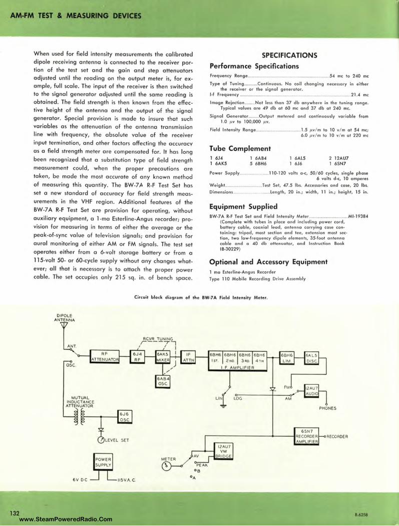
AM-FM TEST & MEASURING DEVICES
When used for field intensity measurements the calibrated dipole receiving antenna is connected to the receiver portion of the test set and the gain and step attenuators adjusted until the reading on the output meter is, for example, full scale. The input of the receiver is then switched to the signal generator adjusted until the same reading is obtained. The field strength is then known from the effective height of the antenna and the output of the signa l generator. Special provision is made to insure that such variables as the attenuation of the antenna transmission line with frequency, the absolute value of the receiver input termination, and other factors affecting the accuracy as a field strength meter are compensated for. It has long been reco~nized that a substitution type of field strength measurement could , when the proper precautions are taken, be made the most accurate of any known method of measuring this quantity. The BW-7A R-F Test Set has set a new standard of accuracy for fiefd strength measurements in the VHF region. Additional features of the BW-7 A R-F Test Set are provision for operating, without auxiliary equipment, a 1-ma Esterline-Angus recorder; provision for measuring in terms of either the average or the peak-of-sync value of television signals; and provision for aural monitoring of either AM or FM signals. The test set operates either from a 6-volt storage battery or from a 115-volt 50- or 60-cycle supply without any changes whatever; all that is necessary is to attach the proper power cable. The set occupies only 215 sq . in . of bench space.
SPECIFICATIONS
Performance Specifications Frequency Ronge .. ..... .... ...... ................. .......... ............ ...... 54 me lo 240 me
Type of Tuning .......... Continuous. No coil changing necessary in either the receiver or the signal generator.
l•f Frequency ........................... ....... .... .... ................. ........... .. .. ... .. .. ... 21.4 me
Image Rejection ........ Not less than 37 db anywhere in the tuning range. Typical values ore 49 db at 60 me and 37 db at 240 me.
Signal Generotor ..... ... Output metered and continuously variable from 1.0 µ. v to 100,000 µ.v.
Field Intensity Ronge .. .... .................. .... ...... 1.5 µ. v/ m to 10 v/ m at 54 me; 6 .0 µ. v/ m lo 10 v/ m at 220 me
Tube Complement 1 6J4 1 6AK5
1 6AB4 5 68H6
1 6AL5 1 6J6
2 12AU7 1 6SN7
Power Supply ........ .............. 110• 120 volts O · C, 50/ 60 cycles, sing le phase 6 volts d•c, 10 amperes
Weight.. ...... .................... Tesl Set, 47.5 lbs. Accessories and case, 20 lbs. Dimensions .......................... .. Length , 20 in .; width, 11 in.; height, 15 in .
Equipment Supplied BW-7A R-F Test Set and Field Intensity Meter ............ ...... ............ Ml -19384
(Complete with tubes in place and including power cord, battery cable, coaxial lead, antenna carrying case con• taining : tripod, most section and tee, extension mast sec• lion, two low-frequency dipole elements, 35.foot ontenno coble and a 40 db ollenuotor, and Instruction Book 18-30229)
Optional and Accessory Equipment 1 mo Esterline-Angus Recorder Type 110 Mobile Recording Drive Assembly
Circuit block diagram of the BW-7 A Field Intensity Meter.
132
DIPOLE ANTENNA
ANT.
osc.
MUTUAL
RFATTENUATO
:r~~~Jtf5/
LEVEL SET
6V DC IISVA. C.
RCVR TUNING r---,7 I I I
I 6BH6 68H6 6BH6 68H6 ISl. 2ND 3AO. 4 1 H
I F AMPLIFIER
LIN LOG
PHONES
6SN7 ,-------------- RECORDER RECORDER
AMPLIF IER
B.6258 www.SteamPoweredRadio.Com
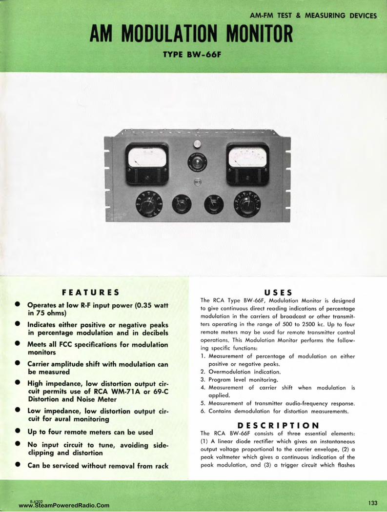
AM-FM TEST & MEASURING DEVICES
AM MODULATION MONITOR TYPE BW-66F
FEATURES
• Operates at low R-F input power (0.35 watt in 75 ohms)
• Indicates either positive or negative peaks in percentage modulation and in decibels
• Meets all FCC specifications for modulation monitors
• Carrier amplitude shift w ith modulation can be measured
• High impedance, low distortion output circuit permits use of RCA WM-71A or 69-C Distortion and Noise Meter
• Low impedance, low distortion output circuit for aural monitoring
• Up to four remote meters can be used
• No input circuit to tune, avoiding sideclipping and distortion
• Can be serviced without removal from rack
8.6302
USES The RCA Type BW-66F, Modulation Monitor is designed to give continuous direct reading indications of percentage modulation in the carriers of broadcast or other transmitters operating in the range of 500 to 2500 kc. Up to four remote meters may be used for remote transmitter control operations. This Modulation Monitor performs the following specific functions : 1. Measurement of percentage of modulation on either
positive or negative peaks. 2. Overmodulation indication. 3. Program level monitoring. 4. Measurement of carrier shift when modu lation is
applied. 5. Measurement of transmitter audio-frequency response. 6. Contains demodulation for distortion measurements.
DESCRIPTION The RCA BW-66F consists of three essential elements: {l ) A linear diode rectifier which gives an instantaneous output voltage proportional to the carrier envelope, (2) a peak voltmeter which gives a continuous indication of the peak modulation, and (3) a trigger circuit which flashes
133 www.SteamPoweredRadio.Com
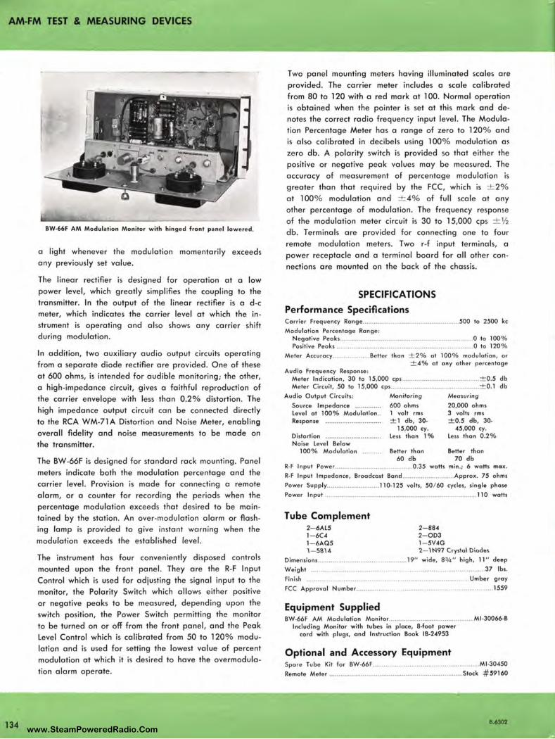
AM-FM TEST & MEASURING DEVICES
134
BW•66F AM Modulation Monitor with hinged front panel lowered.
a light whenever the modulation momentarily exceeds any previously set value.
The linear rectifier is designed for operation at a low power level, which greatly simplifies the coupling to the transmitter. In the output of the linear rectifier is a d-c meter, which indicates the carrier level at which the instrument is operating and also shows any carrier shift during modulation.
In addition, two auxiliary audio output circuits operating from a separate diode rectifier are provided. One of these at 600 ohms, is intended for audible monitoring; the other, a high-impedance circuit, gives a faithful reproduction of the carrier envelope with less than 0.2% distortion . The high impedance output circuit can be connected directly to the RCA WM-71 A Distortion and Noise Meter, enabling overall fidelity and noise measurements to be made on the transmitter.
The BW-66F is designed for standard rack mounting . Panel
meters indicate both the modulation percentage and the carrier level. Provision is made for connecting a remote alarm, or a counter for recording the periods when the percentage modulation exceeds that desired to be maintained by the station. An over-modulation alarm or flash ing lamp is provided to give instant warning when the
modulation exceeds the established level.
The instrument has four conveniently disposed controls mounted upon the front panel. They are the R-F Input Control which is used for adjusting the signal input to the monitor, the Polarity Switch which allows either positive or negative peaks to be measured, depending upon the switch position, the Power Switch permitting the monitor to be turned on or off from the front panel, and the Peak Level Control which is calibrated from 50 to 120% modulation and is used for setting the lowest value of percent modulation at which it is desired to have the overmodulation alarm operate.
Two panel mounting meters having illuminated scales are provided. The carrier meter includes a scale calibrated from 80 to 120 with a red mark at 100. Normal operation is obtained when the pointer is set at this mark and denotes the correct radio frequency input level. The Modulation Percentage Meter has a range of zero to 120% and is also calibrated in decibels using 100% modulation a~ zero db. A polarity switch is provided so that either the positive or negative peak values may be measured . The accuracy of measurement of percentage modulation is greater than that required by the FCC, which is ± 2% at 100% modulation and ± 4% of full scale at any other percentage of modulation. The frequency response of the modulation meter circuit is 30 to 15,000 cps + ½ db. Terminals are provided for connecting one to four remote modulation meters. Two r-f input terminals, a power receptacle and a terminal board for all other connections are mounted on the back of the chassis.
SPECIFICATIONS
Performance Specifications Carrie r Frequency Range .................................................... 500 to 2500 kc
Modulation Percentage Rang e : Negative Peaks ... ......... ............................................................ O to 100% Positive Peaks .................................... ...................................... 0 to 120%
Mete r Accuracy .................... Be tter than ± 2% at 100% modulation , or ± 4% at any othe r percentage
Audio Freque ncy Response: Meter Indication , 30 to 15,000 cps .......................................... ± 0 .5 db Meter Circuit, 50 to 15,000 cps ... ... ...................................... ... . ± 0 .1 db
Aud io Output Circuits:
Source Impedance ............. . Level at 100% Modulation .. Response ............................. .
Distortion ............................. . Noise Level Below
100% Modulation ......... .
Monitoring
600 ohms l volt rms ± 1 db, 30•
15,000 cy. Less than l %
Bette r than 60 db
Measuring
20,000 ohms 3 volts rm s ± 0.5 db, 30.
45,000 cy. Less than 0 .2%
Better than 70 db
R· F Input Powe r .. ........................................ 0 .35 watts min .; 6 watts max.
R· F Input Impedance, Broadcast Band ............................ Approx. 75 ohms
Power Supply ..... ....................... 110•125 volts, 50/ 60 cycles, single phase
Power Input ........................ ................. ......................................... 110 watts
Tube Complement 2- 6Al5 l - 6C4 l - 6AQ5 1- 5814
2- 884 2- 0D3 l - 5V4G 2- 1 N97 Crystal Oiodeo
Dimension s .... ................ ..... ..... .. . ............ 19" wide, 8¾" high , 11 " deep
Weight .. ........ ..•.. ............... ............................. ................................. 37 lbs.
Finish ........... ......................................................................... Umber gray
FCC Approval Number .................................... ............... ..................... 1559
Equipment Supplied BW•66F AM Modulation Monito r .............. ................................ M1 ·30066·B
Including Monitor with tubes in place, 8•foot power cord with plugs, and Instruction Book (B.24953
Optional and Accessory Equipment Spa re Tube Kit fo r BW•66F ............................ .............................. Ml •30450
Remote Meter ........... ....................................... ...................... Stock # 59160
8.6302 www.SteamPoweredRadio.Com
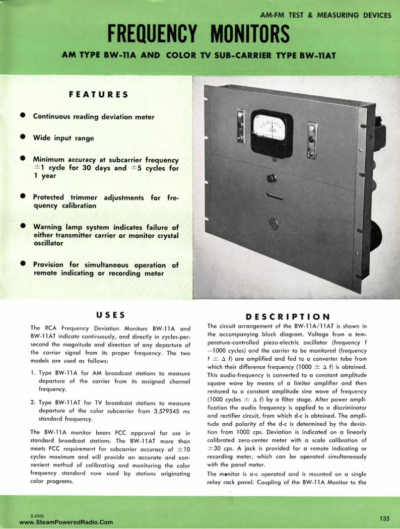
AM-FM TEST & MEASURING DEVICES
FREQUENCY MONITORS AM TYPE BW-11A AND COLOR TV SUB-CARRIER TYPE BW-11AT
FEATURES
• Continuous reading deviation meter
• Wide input range
• Minimum accuracy at subcarrier frequency ± 1 cycle for 30 days and + 5 cycles for 1 year
• Protected trimmer adjustments for frequency calibration
• Warning lamp system indicates failure of either transmitter carrier or monitor crystal oscillator
• Provision for simultaneous operation of remote indicating or recording meter
USES
The RCA Frequency Deviation Monitors BW-11 A and BW-11 AT indicate continuously, and d irectly in cycles-persecond the magnitude and direction of any departure of the carrier signal from its prope r frequency. The two models are used as follows:
l . Type BW-11 A for AM broadcast stations to measure departure of the carrier from its assigned channel frequency.
2. Type BW-llAT for TV broadcast stations to mea sure departure of the color subcarrier from 3.579545 me standard frequency .
The BW-11 A monitor bears FCC approval for use in standard broadcast stations. The BW-1 lAT more than meets FCC requirement for subcarrier accuracy of + l 0 cycles maximum and will provide an accurate and convenient method of calibrating and monitoring the color frequency standard now used by stations originating color programs.
B.6306
DESCRIPTION The circuit arrangement of the BW-11 A/ 11 AT is shown in the accompanying block diagram. Voltage from a temperature-controlled piezo-electric oscillator (frequency f - 1000 cycles) and the carrier to be monitored (frequency f ± A f) are amplified and fed to a converter tube from which their difference frequency (l 000 + A f ) is obtained. This audio-frequency is converted to a constant amplitude square wave by means of a limiter amplifier and then restored to a constant amplitude sine wave of frequency (l 000 cycles ± A f ) by a filter stage. After power amplification the audio frequency is applied to a discriminator and rectifier circuit, from which d-c is obtained. The amplitude and polarity of the d -c is determined by the deviation from l 000 cps. Deviation is indicated on a linearly calibrated zero-center meter with a scale calibration of ± 30 cps. A jack is provided for a remote indicating or recording meter, which can be operated simultaneously with the panel meter.
The menitor is a -c operated and is mounted on a single relay rack panel. Coupling of the BW-11 A Monitor to the
135 www.SteamPoweredRadio.Com
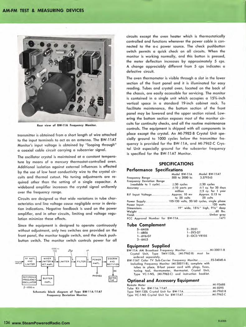
AM-FM TEST & MEASURING DEVICES
136
Rear view of BW-11A Frequency Monitor.
transmitter is obtained from a short length of wire attached
to the input terminals to act as on antenna. The BW-11 AT Monitor's input voltage is obtained by " looping through"
a coaxial coble circuit carrying a subcorrier signal.
The oscillator crystal is maintained at a constant tempera
ture by means of a mercury thermostat-controlled oven.
Additional isolation against external influences is effected
by the use of low heat conductivity wire to the crystal cir
cuits and thermal cutout. No tuning adjustments ore re
quired other than the setting of a single capacitor. A
wideband amplifier increases the crystal signal uniformly
over the frequency range .
Circuits ore designed so that wide variations in tube char
acteristics and line voltage cause negligible error in devia
tion indications. Negative feedback is used on the power
amplifier, and in other circuits, limiting and voltage regu
lation minimize these effects.
Since the equipment is designed to operate continuously
without adjustment, only two switches ore provided on the
front panel , the monitor toggle switch, and the check push
button switch. The monitor switch controls power for all
RF AMPL AND
LIMITER
REFERENCE FR~QUENCY OSCILLATOR
f ·IOOON
HET.AMPL.
BUF FE R
AMPL.
LIMITER
Schematic block diagram of Type BW• 11 A/ 11 AT Freque ncy Devia tion Monitor
circuits except the oven heater which is thermostatically
controlled and functions whenever the power coble is con
nected to the o-c power source. The check pushbutton
switch permits a quick check on all circuits. When the
monitor is working normally, and this button is pressed,
the meter deflection increases by approximately 5 cps.
A change appreciably different from 5 cps indicates a
defective circuit.
The oven thermometer is visible through a slot in the lower
section of the front panel and it is illuminated for easy
reading . Tubes and crystal oven, located on the bock of
the chassis, ore easily accessible for servicing. The monitor
is contained in a single unit which occupies a 15¾-inch
vertical space in a standard 19-inch cabinet rock. To
facilitate maintenance, the bottom section of the front
panel may be lowered and the upper section raised. low
ering the bottom section exposes most of the monitor cir
cuits for continuity checks, and all the routine maintenance
controls. The equipment is shipped with all components in
place except the crystal. An Ml -7982-B Crystal Unit spe
cially ground to l 000 cycles below the transmitter fre
quency is provided for the BW-11 A, and Ml -7962-C Crys
tal Unit especially ground for the subcorrier frequency
is specified for the BW-llAT Monitor.
SPECIFICATIONS Performance Specifications
Model BW-11A Frequency Range ..................... . 500 to 2000 kc Frequency Deviation Rang e
Model BW-11AT 3.579545
(readable to 1 cycle ) ........ . ± 30 cycles ± 30 cycles Accuracy ................. ................. .. ± 10 parts per ± 1 cy. for 30 days
million ± 5 cy. for 1 year R-F Input Voltage ...................... Approx. 10 mv Approx. 0 .15 to
to 25 volts 25 volts Power Supply....... .... 105• 130 volts, 50/ 60 cycles, single phase Power Input.. ............... ....... . .............................................. 120 walls Dimensions .... .............. ...... ... .... .. 19" wide, 15¾" high, 9%" deep Weight .............. ............ ...... .. .. ............................................ 60 lbs. Finish ................. ...... .......................................... ......... . ........... Umber gray FCC Approval Number for BW• 11 A ...... ............................................ 1471
Tube Complement 5- 6AU6 1- 6BE6 1- 6V6-GT 3- 6Al5
Equipment Supplied
2- 2D21 1- 5Y3-GT 2- OC3 / VR105
BW-11 A AM Broadcast Frequency Monitor .............................. Ml -30011 ·B Crystal Unit, Type TMV-135L, (Ml -7962-B) must be
ordered separate ly. BW-1 lAT Color TV Sub-Carrier Frequency Monitor ....... ........ ES-34040-A
Including Frequency Monitor (Ml•30011 -B), complete with tubes in place, 8-foat power cord with plugs, fuses , tuning tool, thermometer, th ermostat, Crystal Un it, Type VC-1-NS, (Ml -7962.C) and instruction booklet.
Optional and Accessory Equipment Remote Meter ... ..................................................... .. ................... Ml -93688 Tube Kit for BW-l lA / 1 lAT.. ............ . ................................ Ml -8295 Type TMV-135L Crystal Unit for 8W-11A ......................... Ml -7962-B Type VC-1-NS Crystal Unit for BW•llAT .................................. Ml -7962-C
8.6306 www.SteamPoweredRadio.Com

AM-FM TEST & MEASURING DEVICES
FREQUENCY MONITOR ANO MODULATION METER TYPE 335-BR
FEATURES
• Provides accurate check that FM transmitter is operating within FCC specifications
• Operates reliably over long periods of time
• Compact size, requ ires minimum rack space
USES The Type 335-BR Frequency and Modulation Meter moni
tors FM transmitters reliably, accurately, over long periods
of time. No adjustments are necessary during operation,
and because the instrument does not depend on a tuned
circuit, it is not necessary to re-set the carrier level or
re-align circuits. The instrument is specifically designed
to operate without adjustment week after week . It gives
continuous indication of broadcast fre quency and of modu
lation level at all times, and has FCC type approval.
B.6310
• External meters may be remotely located
• Simplified operation, no ad justments necessary during operation
• Continuous indication of broadcast frequency and modulation
DESCRIPTION A low-temperature co-efficient crystal, oscillating inside
a temperature-controlled oven, provides a reference stand
ard of approximately 5 me. The output of this crystal
oscillator is multiplied 20 times, and mixed with the trans
mitter frequency to form a 200 kc intermediate frequency .
This frequency is fed into electronic counter circuits, which
measure the intermediate frequency and thereby indicate
th ca rrier deviation. The linear counter circuits also pro
vide a measurement of percentage modulation as well as
137 www.SteamPoweredRadio.Com
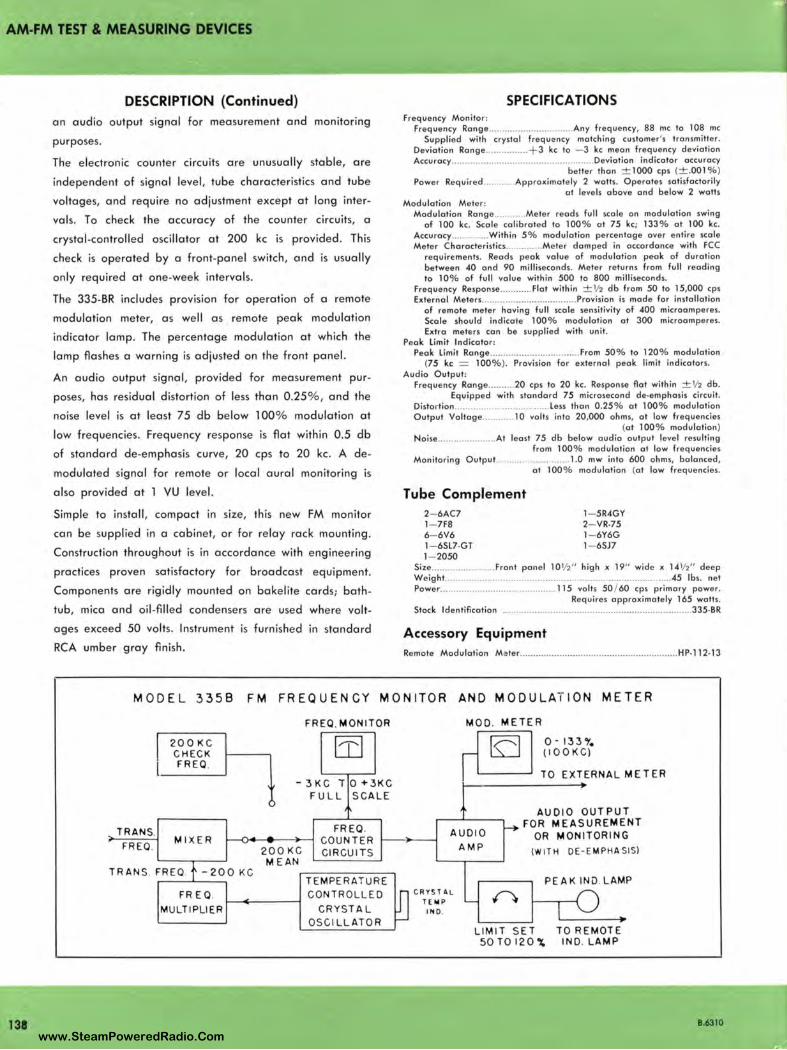
AM-FM TEST & MEASURING DEVICES
138
DESCRIPTION (Continued)
an audio output signal for measurement and monitoring
purposes.
The electronic counter circuits are unusually stable, are
independent of signal level, tube characteristics and tube
voltages, and require no adjustment except at long inter
vals. To check the accuracy of the counter circuits, a
crystal-controlled oscillator at 200 kc is provided. This
check is operated by a front-panel switch, and is usually
only required at one-week intervals.
The 335-BR includes provision for operation of a remote
modulation meter, as well as remote peak modulation
indicator lamp. The percentage modulation at which the
lamp flashes a warning is adjusted on the front panel.
An audio output signal, provided for measurement pur
poses, has residual distortion of less than 0.25%, and the
noise level is at least 75 db below 100% modulation at
low frequencies. Frequency response is flat within 0.5 db
of standard de-emphasis curve, 20 cps to 20 kc. A de
modulated signal for remote or local aural monitoring is
also provided at l VU level.
Simple to install, compact in size, this new FM monitor
can be supplied in a cabinet, or for relay rack mounting.
Construction throughout is in accordance with engineering
practices proven satisfactory for broadcast equipment.
Components are rigidly mounted on bakelite cards; bath
tub, mica and oil -filled condensers are used where volt
ages exceed 50 volts. Instrument is furnished in standard
RCA umber gray finish .
SPECIFICATIONS Frequency Monitor :
Frequency Range ................................ Any frequ e ncy, 88 me to 108 me Supplied with crystal frequency matching customer's transmitter.
Deviation Range ................ + 3 kc to - 3 kc mean frequency deviation Accuracy ...................................................... Deviotion indicator accuracy
be tter than ± 1000 cps (±.001 %) Power Required ........... Approximate ly 2 watts. Operates satisfactorily
at leve ls above and below 2 watts Modulation Meter :
Modulation Range ............ Meter reads full scale on modulation swing of 100 kc. Scale calibrated to 100 % at 75 kc; 133 % at 100 kc.
Accuracy .............. Within 5% modulation percentage over e ntire scale Meter Characteristics .............. Mete r damped in accordance with FCC
requirements . Reads peak value of modulation peak of duration between 40 and 90 milliseconds. Meter returns from full reading to 10% of full value within 500 to 800 milli seconds.
Frequency Response ............ Flat within ±½ db from 50 to 15,000 cps External Meters ................•................... Pravision is made for installation
of remote meter having full scale sensitivity of 400 microamperes. Scale should indicate 100% modulation at 300 microamperes. Extra mef·e rs can be supplied with unit.
Peak limit Indicator : Peak limit Range ................... ............... From 50% to 120% modulation
(75 kc = 100%). Provision for external peak limit indicators. Audio Output:
Frequency Range .......... 20 cps to 20 kc. Response flat within ± ½ db . Equipped with standard 75 microsecond de•emphasis circuit.
Disto rtion .................................... less than 0 .25 % at 100% modulation Output Voltage ............ 10 volts into 20,000 ohms, at low frequencies
(at 100% modulation ) Noise ...................... At least 75 db below audio output level resulting
from 100% modulation at low frequencies Monitoring Output ............................ 1.0 mw into 600 ohms, balanced,
Tube Complement 2- 6AC7 1- 7F8 6- 6V6 1- 6Sl7-GT 1- 2050
al 100% modulation (at law frequencies .
1- 5R4GY 2- VR-75 1- 6Y6G 1- 6SJ7
Size ........................ Front panel 10½ " high x 19" wid e x 14½ " deep Weight ..................................................................................... .45 lbs. net Power ............................................ 115 volts 50 / 60 cps prima ry power.
Requires approximately 165 watts. Stock Identification ........................................................................ 335. BR
Accessory Equipment Remote Modulation Mater ........................ .... ................................ HP· 112· 13
MODE L 3 358 FM FREQUENCY MON ITOR
FREQ. MON IT OR
AND MODU L ATI ON METER
MOD. ME TER
T RAN S. FREQ.
200 KC CHECK FRE Q.
M IXER
TR ANS . FREQ -200 KC
FRE Q. MULTI PLIE R
' -3KC T0+3KC FULL SCALE
')
200 KC M EAN
FREQ. COUNTER CIRCUITS
TE MPERATURE CONTROLLED
CRYST A L OSCILL ATOR
A UDIO A MP
CRYSTAL TE MP
IND .
0-133o/. (IOOKC)
TO EXT ERNA L M ET ER
AUD I O OUT PUT FOR M E ASU REMENT
OR MON ITOR I NG
(WITH DE - EMPHASIS)
PE A K IND. L AMP
LI MIT SET 50 TO 120 o/.
TO RE MOTE I ND. LAMP
B.6310
www.SteamPoweredRadio.Com
wigfi
Stolen 2 Line Transparent
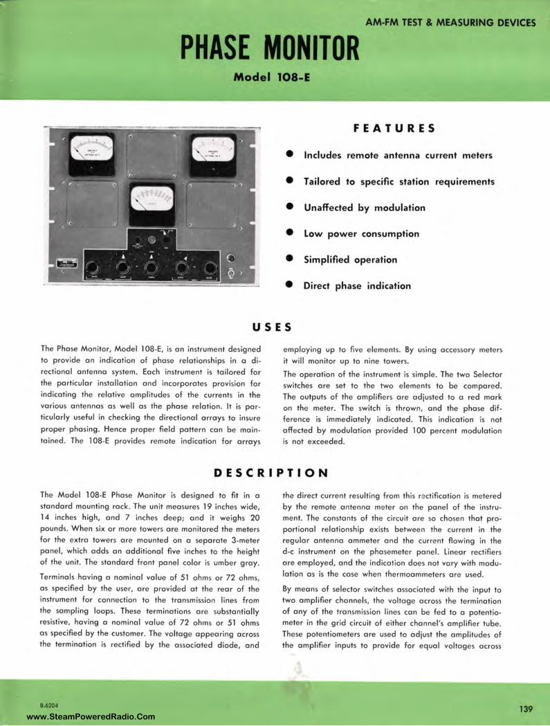
AM-FM TEST & MEASURING DEVICES
PHASE MONITOR Model 108-E
FEATURES
• Includes remote antenna current meters
• Tailored to specific station requirements
• Unaffected by modulation
• Low power consumption
• Simplified operation
• Direct phase indication
USES
The Phase Mon itor, Model 108-E, is on instrument designed to provide on indication of phase relationships in a directional antenna system. Each instrument is tailored for the particular installation and incorporates provision for ind icating the relative amplitudes of the currents in the various antennas as well as the phase relation . It is particularly useful in checking the directional arrays to insure proper phasing. Hence proper field pattern con be maintained. The 108-E provides remote indication for arrays
employing up to five elements. By using accessory meters it will monitor up to nine towers.
The operation of the instrument is simple. The two Se lector switches ore set to the two elements to be compared. The outputs of the amplifiers ore adjusted to a red mark on the meter. The switch is thrown, and the phase difference is immediately indicated . This indication is not affected by modulation provided 100 percent modulation is not exceeded.
DESCRIPTION
The Model 108-E Phase Monitor is designed to fit in a standard mounting rock . The unit measures 19 inches wide, 14 inc hes high, and 7 inches deep; and it weighs 20 pounds. When six or more towers ore monitored the meters for the extra towers ore mounted on a separate 3-meter panel, which odds on additional five inches to the height of the unit. The standard front panel color is umber gray.
Terminals having a nominal value of 51 ohms or 72 ohms, as specified by the user, ore provided at the rear of the instrument for connection to the transmission lines from the sampling loops. These terminations ore substantially resistive, having a nominal value of 72 ohms or 51 ohms as specified by the customer. The voltage appearing across the termination is rectified by the associated diode, and
B.6204
the direct current resulting from this rectification is metered by the remote antenna meter on the panel of the instrument. The constants of the circuit ore so chosen that proportional relationship exists between the current in the regular antenna ammeter and the current flowing in the d-c instrument on the phosemeter panel. Linear rectifiers ore employed, and the indication does not vary with modulation as is the case when thermoommeters ore used .
By means of selector switches associated with the input to two amplifier channels, the voltage across the termination of any of the transmission lines con be fed to a potentiometer in the grid circuit of either channel 's amplifier tube . These potentiometers ore used to adjust the amplitudes of the amplifier inputs to provide for equal voltages across
139 www.SteamPoweredRadio.Com
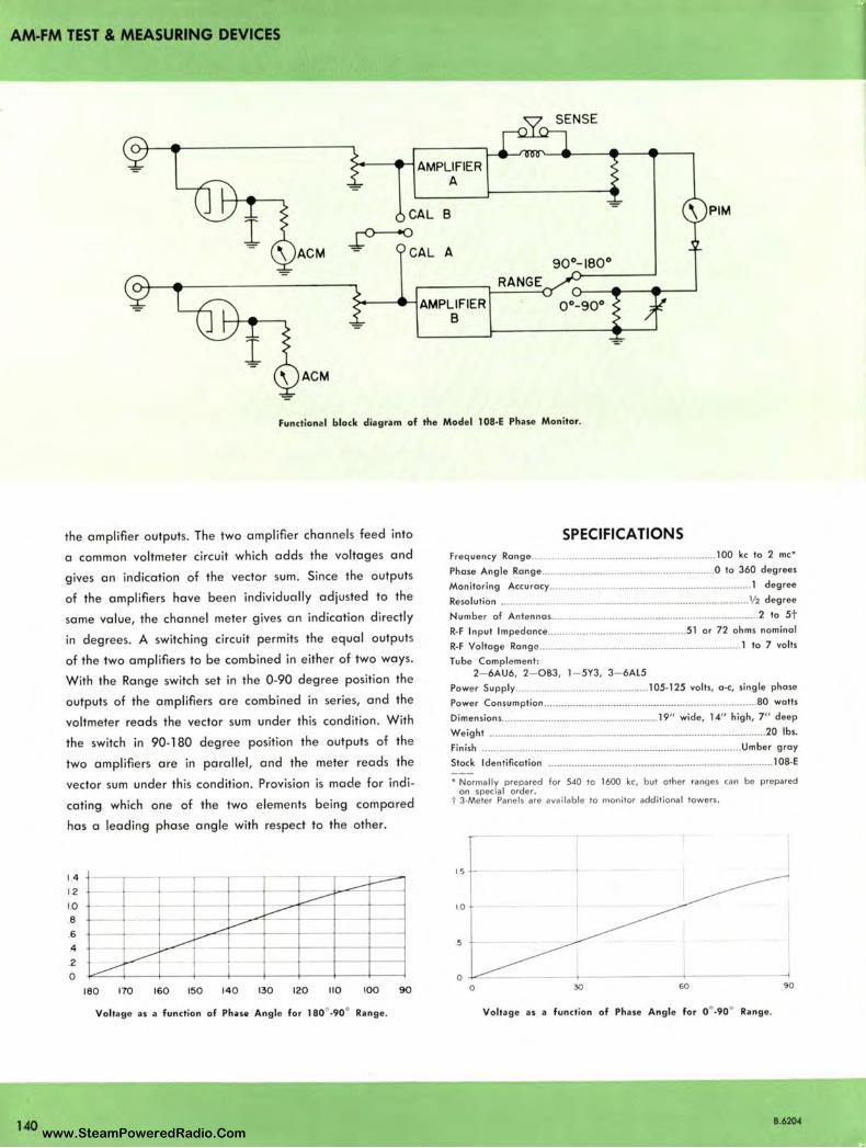
AM-FM TEST & MEASURING DEVICES
140
~ - -e--1 AMPLIFIER A
l CAL B
~CAL A 90°-180°
= RANGE
>--- -e-1 AMPLIFIER 0°- 90° B
l ACM
Functional block diagram of the Model 108·E Phase Monitor.
the amplifier outputs. The two amplifier channels feed into
a common voltmeter circuit which adds the voltages and
gives an indication of the vector sum. Since the outputs
of the amplifiers have been individually adjusted to the
same value, the channel meter gives an indication directly
in degrees. A switching circuit permits the equal outputs
of the two amplifiers to be combined in either of two ways.
With the Range switch set in the 0.90 degree position the
outputs of the amplifiers are combined in series, and the
voltmeter reads the vector sum under this condition. With
the switch in 90-180 degree position the outputs of the
two amplifiers are in parallel , and the meter reads the
vector sum under this condition. Provision is made for indi
cating which one of the two elements being compared
has a leading phase angle with respect to the other.
14
1.2
1.0
.8
.6
.4
.2
0
180 170 160 150 140 130 120 110 \00 90
Voltage as a function of Phase Angle for 180° .90° Range.
SPECIFICATIONS Frequ ency Range.. .. . ................................................. 100 kc to 2 me•
Phase Angle Rang e ............................................................ 0 to 360 degrees
Monitoring Accu racy ..... ............•. .......... .... .... ........ ..... ... ........... .... . 1 degree
Resolution ...................................................................................... ½ degree
Number of Antenna s .... ............. ... .... ....................................... ... ..... 2 to St R-F Input Impedance ...................................... ......... 51 or 72 ohms nominal
R•f Voltage Rongc ............................................................ .......... l to 7 volts
Tube Complement : 2- 6AU6, 2- 083, l - 5Y3, 3- 6AL5
Powe r Supply .................................... .......... 105• l 25 volts, O· C, single phase
Power Consumption .......................................................................... 80 watts
Dimensions ........................................... ........... 19" wide, 14" high, 7" deep
Weight ..... ..... .... .................. .................................. .............................. 20 lbs.
Finish ...... ...... ............ .................... ... .. ..... ........ .. ... ....................... Umber gray
Stock Ident ificat ion .... .. ................. ....... ........ ........................................ 108·E
• Normally prepared for 540 to 1600 kc, but other ranges can be prepared on specia I order.
t 3-Meter Panels are availab le to monitor additional towers.
0 30 60 90
Voltage as a function of Phase Angle for 0 °.90° Range.
8.6204 www.SteamPoweredRadio.Com
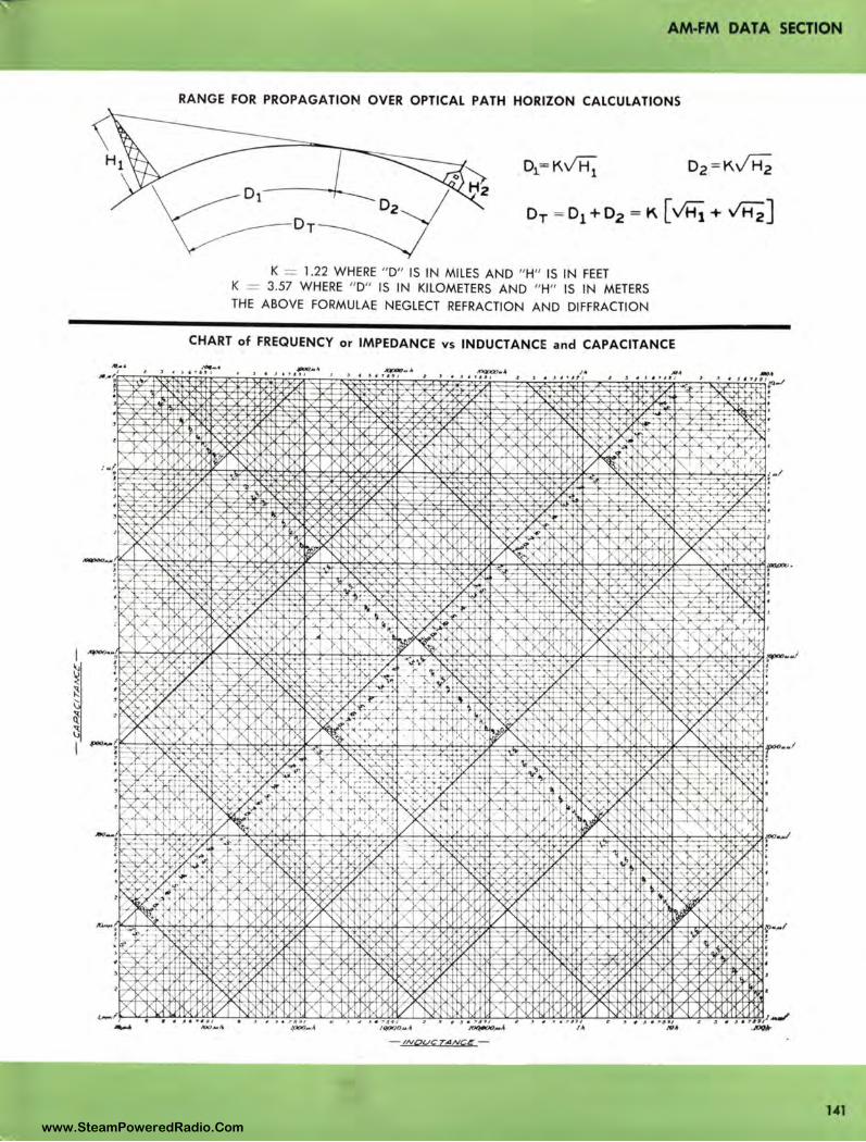
AM-FM DATA SECTION
RANGE FOR PROPAGATION OVER OPTICAL PATH HORIZON CALCULATIONS
K = 1.22 WHERE " D" IS IN MILES AND " H" IS IN FEET K = 3.57 WHERE " D" IS IN KILOMETERS AND " H" IS IN METERS
THE ABOVE FORMULAE NEGLECT REFRACTION AND DIFFRACTION
CHART of FREQUENCY or IMPEDANCE vs INDUCTANCE and CAPACITANCE _,.. .I , ' J . ,,,,
~ - >{
'r' µ'~
' Ix 'li / 1.)<
I), 1/ . ., ., .... , __ ,. ' "~
>,[-~ ~
;
"' "i's K .X. )"-vk
)< ')
'
~ L )' /
It / ,)'. ' ✓
It I), ~ ~ " t ~O,,...A
- /NQUC TANC{: -
... . ~ J ~ I • r I, I
:. l/ ,, V
' rs;: 1' I :,1Y "' 1'. r--1, r, IJ :/N"1
l"'- K N r--: I/ ~ 'is
--,; '
-c•
' , . ' · " X 7 Kr-;: / ' J lX 1;
~ / t<: l/k "' 11/ I\. ~
3 I , 1fl ,.
h ~ k
I) r-1 . '
1"1 www.SteamPoweredRadio.Com
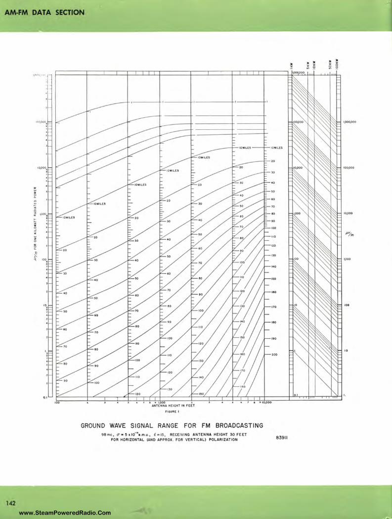
AM-FM DATA SECTION
:!; ~
~ Q w .. ~ "' ~ ~ ; 3 ;; w :z 0
"' ~
~ 'l_
142
FIGURE I
GROUND WAVE SIGNAL RANGE FOR FM BROADCASTING 98mc, 0- • 5alo·", .m.u., l-15, RECEIVING ANTENNA HEIGHT 30 FEET
FOR HORIZONTAL (AND APPROX. FDR VERTICAL) POLARIZATION
IOMILES
20
100,000
30
40
,o
60
70
,o 10,000
90
100
110 Jl!l'm
120
130 1,000
140
IOO
110
170 100
100
190
10 200
83911
www.SteamPoweredRadio.Com

I-u..
0 0 0 ~
~ co 0
1./) 1./)
0 ...J
AM-FM DATA SECTION
1.0
0.5
/ V
/
/
/' V ,/
/
0.1 V
.~
~V ,,,, 0.05
0.01 200
~ ,/
,, ~
~ ...... ,/'
\b. ~
<Y'-- ,/ ,/'
Q9~ _,,,., .X I \1. _J>
.,,,,. ~ .,,, I \cf-- ./ _/
..... ~
093:--r ~ ~ ~ 11 \b.
.,,,,,. ..... ,/' _J> o--- ~ ~
V I b.i-\ .,,,,,. ..... ()9 b. .,,,,,. _/ __.. \ - \0
~ V ()9bi-~ ./ ,JI'
/ "I I 0 ---✓ .,,r / ()9\,,,, / ,JI'.,,,,.
/ .,
/ / ,,,,,.. __..\~ ~
\0 (59-:,t,,,
~.,,,,. ..... ~
/
LOSS (DB /1 000') = 0.224 V f o: fox 0-
fo = l 000 KC S
(Jo=l00x 10- 15 e.m.u.
IO-l5f ll11
(iEi iA1/
1000
FREQUENCY IN KILOCYCLES
V 2000
LOSS (DB PER 1000 FT.) OF RCA 6 WIRE TRANSMISSION LINE LINE HEIGHT 12', WIRE SPACING 15", WIRE SIZE #8, Zo= 230 .J\...
143 www.SteamPoweredRadio.Com
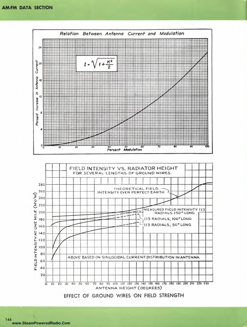
AM-FM DATA SECTION
144
4
28 0
260 ,..,_ ~ 24 0 ~ ::E 22 0
V
~ 20 0
~ 180 lU z 16 0 0
~ 140
> I- 12 0 (/\
Z 100 w
~ 80
9 60 w i.L 4o
20
Relation Between Antenna Current and Modulation
,0 20 30 50 60 ,0 80 90 Percenf Modulation
FIELD INTENSITY VS. RADIATOR HEIGHT FOR SEVERA L L E N G TH S OF GROUND WIRES .
-T H EO R E TI C A L F IELD -~ V
INT E NSIT Y OY E R P ERFECT EARTH V ~ V J.-+--,-
-~ ::::;:::MEASU R ED F IELD INTENSITY I 13
-- --· - RADIALS 150° LONG --.....- -- --- 113 RADIALS, I00°L0NG
.,V -- i.--- '1113 RADIAL$, 50° LONG -- --- ---1--
V -~ .....----I ... v --
I , V
I J ABOVE BASE D ON SI NUSOIDAL CURRENT DISTRIBUTION IN ANTENNA
o 10 20 30 4 0 so Go 70 so so 100 110 120 130 140 ,so 160 110 ,ao 190 200 210 no no ANTENNA HEIGHT (DEGREES)
EFFECT OF GROUND WIRES ON FIELD STRENGTH
www.SteamPoweredRadio.Com
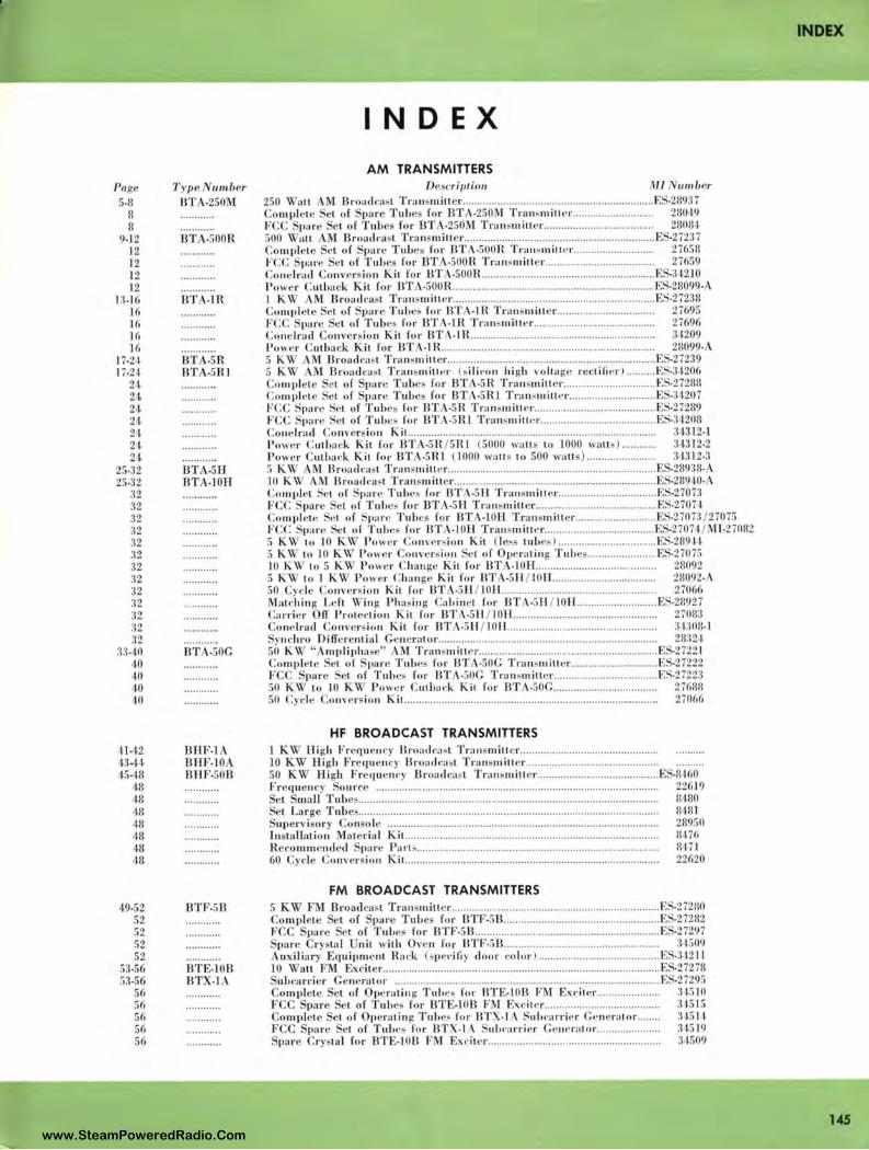
Page 5.3
8 8
9.12 12 12 ]2 12
11-16 16 ]6 ]6 ]6
] 7-24 17.2,1
24 24 24 24 24 24 24
25-32 25.32
:J2 32 :{2 :12 32 :12 32 32 :12 n :32 32 32
13-40 40 40 40 40
41-42 43-4,1 45.rn
48 48 48 48 48 48 48
Type 11111ber BT -250M
BT -!>00R
BT -IR
BT . -SR BT -SRI
HT -SH BT .JOH
BT -50G
BHF-1 DflF.10 BHF-50D
,19.52 BTF.5B 52 52 52 52
53-56 BTE-108 53•56 BTX.1
56 56 56 56 56
INDEX
INDEX
AM TRANSMITTERS Descriptio11 M l umber
250 ~ all M Broadcast Tran mitter .. .... .. ... ....... .... ... .......... .... ..... .. .. .. ........... ..... F -28937 Com11lc1 el of pare Tubes for BT -250M Transmitter......... ....... ..... ....... 28019 F C pare et of Tub for BTA•250M TransmiLLcr.. .. .... .. .... ... ... .. ... ..... ... .. ... 28081 500 ', ' all AM Broadcast Transmill e r ..... ..... .... .... .. .................. ...... ... .... ... .......... .. E •27237 Co mpl ete L of par Tub 's for BTA·S00R Tra11 smit1 r................. ....... .. .. 27658 FCC par • ·L of Tuh for BT •500R Transmiller.... ....... ........................... 27659 Co 11 e lrad Conver io n Kit for HT •500R. .. ............... .... ... ....... ................ .. .......... E -31210 Po, er Cutback Kit for BT -S00R. .......... .. ..... ........ ......... .... .... .. .. .. ...... ... ... ...... ... ES-28099-A l K ~ Broad ca L Tra11 smiller ............... ... .. ...... ... ....... .. .............. ................. . ES-27238 Complete et o f pare Tubes for BTA- 1 R Tra11 smill r .. ....... ................... ..... 27695 FCC Spar •L of Tubes for BTA-IR Transmille r.......... ..... ......... .................. 27696 Co nclrad Conv rsio n Kit for BT -l R ...................... ... .. .... .... .............. ... ............ 3 1209 Power Cutback Kit for BT •Hl.. .................. .... ..... .. .. .. ... ........... .. .... .. .... .. ....... ... 28099-5 K~ M Broadcast Tran miLLer .......... .. ................ ....... .............. ....................... E •27239 5 K'I M Broadca L TransmillPr (~ ili rn n hi gb vo ltage rcctilicr ) .......... ES-3'1206 Co 111p le1 • et of pare Tubes for BT -5R Transmitter .. .... ......... ......... ... ... .. ES.27288 Compl ete et of pare Tulp for BT -5JU Transmitl e r ........ .... .................. E -34207 FCC ·par' el of Tube for BT •SR Tran mill r ... ..... ... ....... .. .................. .. .. E ' •27289 FCC par • St of T uh s for BT •5Rl Tnm mitte r .... ..... ... .............. .......... .... E .:11208 Co ne lrad Co nver ion Ki t. ... ........... .......... ............ ....... .. ..... ............. ... .... ...... ... ...... 34312·1 Power Cutba ck Kit for BTA-5R / 5Rl (5000 walls to 1000 wall ) .. .... ...... 34312-2 Po11 er ut ba ck Kit for BT .5 Rl ( LO00 wa ll lo 500 wa lls). .. .. .................. . 3,n12.3 5 K'I ' A 1 Broaclta l Transmill er ..... ..... ........ .. ... ....... .. ... ...... .......... .... ... .. ............ E 289:rn. 10 K'I l Broatl n 1st Transmiuer ... ................................ ... ....... .... ... ...... ..... ..... .. ES-28940• Co n,pl cL ct of . pare Tubes for BT -5 11. Tran mille r .............................. .... E -27073 F CC Spare el of Tuhes for BTA-5H. T ran smiller ............ .......... .. .................. ES.27074 Compl Le cl o f pare Tub for UTA-LOH Tra11 smi11 r ... ...... ...... ............. E. •27073 / 27075 FCC pare · l of Tubes for BT -101-L Tran miller ... ............. .. .................... E -2707<1/ Ml-27082 5 K ', ' to 10 KW P ower Co nve r ion Kit (]es lube ) ...... ..... .... .. ........... ... ... E •28911 5 K ', ' to .LO K \V P ower Co nversion L o f Operating Tub · ........ ... ... .... .... .. E •2707!> 10 K 'I to 5 K'I Power Chan g· Kit for BT . •l0H.. ...... .. ... ... .. ... .... ............... .. 28092 5 K ~ to l K 'I Power Chan ge Kit for BT -51-T /l0H...... ... .................... ... .... 28092-A 50 Cyd c o nversion Kit for BTA·SH / lOH ... ......... ... ......... .. ... .... .. ... .. .... .... .... . 27066 Mat,·hing Left 'I in g Phas in g Cab inet for BT -5H/l0H .... ... .. ....... .... ....... . b . ·28927 Ca rri er OIT Protection Kit for BTA•5 H /l 0H... ................. .............................. 27083
onelracl o nver ion ii for BT •SU /JOH .............................. .... .......... .. ...... :1130IJ.] ·yncl1ro OilTerenl ial Ge n rator.... ........ ... ..... .... ................ .................................... 2832 1
50 K'I ' ' m1>liphase" M Tram,mittcr .......... .. .... .......... ........ ........... .. ...... .. ....... E. -2722 1 omvl Le ·t £ pare Tube · fo r BT •S0G Transmitler ............... ............. .. E -27222
F pare et of Tubes for BTA•50G Transmitte r .......... ......................... E. '.27223 50 KW 10 10 K'i ' Pow r Cu1l,,,.·k Kit for BT •50G.................................... 2768ll 50 , ycle 011ver ion Kit... ..... .. .... ... .. ... .. .... .... .. ..... .. ..... .. .. ......... .... ............ ............. 27066
HF BROADCAST TRANSMITTERS 1 KY High Frequency Ilroa tl c.1 ol Transmitte r ..... .. ........... ..... ........ ........ ..... ... . 10 K High Freq uency Broatlca I Tra n miller .. .. ..... ..... .. ..... ......... .. ... .. .... .... . 50 K'I High Frec1uc1H·y Broa dcabl Tra11s111ill e r ... .... ... ...... .......................... E. •8160 Frcc1ue11cy ource ............ ....... ..... ... .. .... .................. ...... ........... .. ... ... ................... ... 22619
el mall Tubes ...... ................ ............. ...... ...... ... ........ ............ ........... .. .... ,. ...... ......... 8 180 et Large Tube ......................... ... ... ................... .... ..... .. ......... .................... ...... ..... ... 818] upervi ory 0 11 ole ..... .. .... .. .... ......... ..... .. ..... .......... ....................... ... .. .... .. ........ ... . 28950
111 tallalion Material Kit ..... .......... ... ... ..... ....... .... .. ........... .. ........... .. ........... .. .. ........ 8176 Recom111e11ded pare P art,-...... ...... .. ... ............... .... .. .... .. ... ....... .. ..... .. ... ............ ...... 8 17'1 60 Cycle 011versio11 Kit.. ...... .... .............. ....... ..... .. .... .. ............. ..... .. ... .......... ..... ... . 22620
FM BROADCAST TRANSMITTERS
U5 www.SteamPoweredRadio.Com
wigfi
Stolen 2 Line Transparent
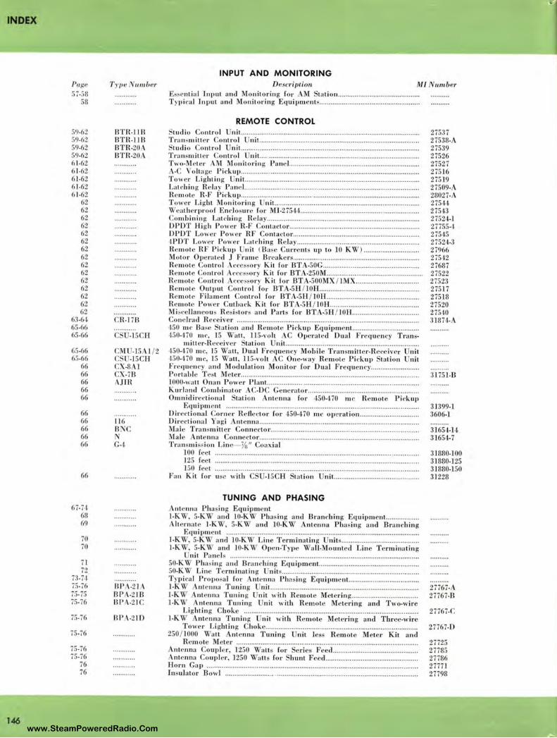
INDEX
146
INPUT AND MONITORING Page T y11e 111111ber Description M l umber 57-58 Es~e ntial In p ut and Mon it o rin g for M ta li on ................ .................. .... ..... .
58 T ypi ca l In put and Mo nit ori ng Eq uipments .... ..... ........... ... ........... .... ............... .
59-62 59-62 59-62 59-62 61-62 61-62 61-62 61-62 61-62
62 62 62 62 62 62 62 62 62 62 62 62 62 62 62
63-6 l 65-66 65-66
65-66 65-66
66 66 66 66 66
66 66 66 66 66
66
67-74 68 69
70 70
71 72
73-H 75-76 75.75 75-76
75-76
75-76
75-76 75-76
76 76
BTR-1 I LI BTR- 118 BTR-20A BTR-20A
.R-178
C -1 5CH
CM -15 1/2 -15 CII
CX-8Al CX-78
JJR
116 B C
G-4
BP -21 BPA-218 BP -21C
BPA-210
REMOTE CONTROL tud io Contro l nit. .................... ... ........... ........ ............ ..... ........ ... ........ ... .. ..... ...... .
Tra nsmitt e r Co ntro l ni t. .... .... ..... .. .... ... ....... ................ ............... ........... .... .. ...... .. ' tudio Contro l nit .......... .. ............. ........ ... .... ......... .. .. ....... ..... .... .......... .... .. ... ...... . . Tran mill e r Co ntro l nit.. ... ......... ..... .. .. ..... ........ ... ...... ........ ... .... ..... .. .. .... ..... ..... . . Two-Meter M Mo nitorin g Pan e l ........ ... ....... .... ..... .. ....... .... , ... ........ .. .... ...... .... ..
-C o lta ge Pi ckup ............ ... ........... ........ ... ... ....................... .. , .... ..... .... ... .. ....... .. .. . To , e r Lightin g njt. ......... .... ...... ...... .......... .......... ...... ....................... . , ........ ........ . Latchin g Re la y Pa ne l ................ ........... ...... ........ ......... ...... ................................ ..... . R •m ote R-F Pickup .. .......... ....... .... ...... ... .. ...... ... ... ..... .. ... ............. ..... .................... . Tower Li ght Mo nito rin g 11i1.. ..... .. ... .... .. .... ... ... ........... .... .. ... ... ... .. .............. .... ... . , · eathe rproo [ Enclosure for M l-27544 .. ... .. .... ..... .. .. ......... ............... ........ .. .. ....... . Combini11 g La tch in g R e lay ............ ....... ... .. ... ... .. ...... .......... .... .... .. ....... ...... .. ........ . DPDT Hi gh Pow r R-F Co ntacto r ...... ... .... ...... ...... ................................... ... ... ... . DPDT Lo we r Powe r RF onta ctor .... ........... ..... .. ............. ........................ ... ..... . ,1.PDT Lower Powe r Lat t· hin g R ela y .. ............ .................. ........... .............. ........ . R 111 0 1 RF Pi ckup nit ( Base urrent up to 10 K, ) ...... ..... .................. . Motor Op •rat ed J Fram e Br ak e r ...... .. .......... ... ... ....... .. ...... .... ................. ... .... . R ' mot Co ntro l c\cc 's ·o ry Kit for BT -50G ........ .. ............ ... ............. ............. . R •m ote Co ntro l Accessory Kit for BT -250M .. ............. ............ ... ........ ............. . R m ote onlro l cces:,o ry Kit for BT -500MX / 1MX .. ... ..... ... .. .................. . R e111 01 • Output Co ntro l fo r BT -5H/10H ....... ........... ........... ............ ....... .. .. . . R e m ote Fi lam ent ontro l for BT -5H / lOH .......... .... .......... .... ..... ...... .... .... .. . R emote P owe r C utback Kit for BT -5H / lO H ................ ... ... .... ..... ........... ..... . M i ce ll aneo us R e istors a nd Part for BT -5H /10H ........................... ....... . . Co n ' lratl R ce iver ..... .......... ....... .... ... ..... .. .. ....... ..... .................................... ....... .. .. . 450 m e Base tali on a nd R em ote Pi ckup Eq u ipm 111.. .. ........ ... ..... .. ........... .. . 450-470 n1t·, 15 a ll , 11 5-volt C Op ra ted Dual Frequ en cy Tran s•
mitt e r-Receiver tali on nit. ....... ..... ........ ..... ........... ...... .......... ... ........ .. .... . . 450--170 me, 15 Wall, Dual Fre,1u •ncy Mob ile Trun milte r-Re c iver U nit 450-170 m e, 15 Wall, ll 5-vo h C One-, a y R 111 01 Pi ckup ta l io n nit Fr •c1u e11 cy a nd 1odulati on Mon it or for Dual Freq ue ncy ... ........ ... ... .. ...... . Portabl e T •st M te r ............. ..... .......... ....... ... ............................. ............... ............. . 1000-wall nan P ow •r Plant.. ....................... .. .... ........ .. ............. .. ....... ...... .. ......... . Kurland Combinator C-DC G n ·ralor .......... .. .... ........ ............. ....... ... ...... ... ... . Omnidire eti ona l tali on nte nna for 450-470 m e Re m ote Pickup
Equ ipm ent .......... .......... ................................. ..... .. ..... ......... ... .............. ... ......... . Directi onal Corner R , Aector for 450-470 m e op ration .... ..... ... ................... . Directi ona l Ya gi nt nml ......... ....... .. ...................... ..... ........ ... .. ............. ... ......... .. . Mal e Tran mille r onn ecto r ....... .............. ........... ...... .... ......... ................... ......... . 1al • nle nna Conn clor ...... .... ........... ..... ....... .......... ....... ......... ..... ............ .. ... .... .
Tran smi sion Lin - 3/u" oax ial 100 [c l ...... . ....................... .. . ............. .. ......................... ..... .. .......... ..... . ...... .... ... . 125 feet ............................. ...... .. .......... .. .......... ......... .... ..... ...... .. ......... ... .. .......... . 150 fc l ............................. ........ .. ..... ..... ... .. .. ........... ... ............ ...... ........ .. ...... ..... .
Fa n Kit for u e with -15 H tali on nit. ........ .. .. ................ ................ .
TUNING AND PHASING 11te 1111n P ha ing Equipment
1- , ' , 5-KW and 10-KW Pha sin g a ncl Branching Eq uipm ent.. ....... .. ...... . A It rna te 1-KW, 5-K and 10-K'\ ntcnna Pha sing and Bran chin g
E quipm ent .. .. .. ........ ..... ......... ..... .... ..................... ........ ............... ... ... ................ . 1-K'I ' , 5- , and 10-KW Li n Termi nating nits .. ..... .. ........... .. ................. .. . 1-K'I , 5-KY and 10-K'i Open-Type Wa ll -Mount cl Lin T erminatin g
nit Pan Is ........ .. ........ ..... ...... ...... .... ....... ........ .......... ... ............ ... .......... .. ..... .. . 50-K'\' Phasin g ancl Branc·ltin g Equipment. .. ................... .......................... .... . . 50-K'\ Linc T e rminatin g nit s ................... .... ...... ........ ............. .............. .. ....... . T ypiea l Proposa l for ntenna Phas in g Eq uipment.. ...................... ........... . .. 1-K'\ A nte nna Tunjng nit .... ................ .......................... ............... ........... ....... . 1- ntenna T unin g nil wi th R emote Meterin ' ···· ·········· ····· ·· ··········· ···· 1-K~ 111enna Tunin g nit w ith R e mote Mete rin g ancl Two-wir
Li ghtin g hoke ...... ... ........ ............ ............ ................. .. ....... ... ................... .... . 1-K,' nte nna T un ing U nit wi th R em ote Meterin g ancl Three-wire
Towe r L ightin g hoke ................ ..... ..... .................... .................. ................. . 250/1000 '\' a ll nl nna Tuning U nit l ess R em ote M Lcr Kit and
R m ole Meter ······················ ·············· ·· ··"·········· ·· ······ ·············"····················•oo nlenna Coupl r , 1250 '\ a lls for c ri e F ed ... ... .......... .. ....... ....... ............. . ntenna ouplcr, 1250 '\ a ll for hunt F ,ed ... ..... ... .. .... .. .... .......................... .
Horn Gap .............................. ... ... ........ ... ... .... ... ....... .......... .... ... ..... .. .......... ............ ... . Insula tor Bowl ..... .......... .... ... ........ ............... ........... ... .. ............ .......... ...... , ........... .
27537 27538-A 27539 27526 27527 275.1 6 27519 27509-28027-275H 27543 27524-1 27755-1 27545 27524-3 27966 27542 27687 27522 27523 27517 27518 27520 27540 31874-
31751-B
31399-1 3606-1
31654-14 31654-7
31880-100 31880-125 31880-150 31228
27767-A 27767-B
27767-C
27767-D
27725 27785 27786 27771 27798
www.SteamPoweredRadio.Com

PngP 77 77 78 78 78 78 78 78 78 -8 78
78 78
79-94 91 94
80 80 80 80 80 80 80 80
T y{J e 11111/,er BP -5 BP -10 BP -50 BP -50
TUNING AND PHASING (Continued) De.<cri(Jtio11 M l
5-K ~ 11te11na Tuning nil ..................... ....................................................... ... . 10-K ~ nten11a T unin g nil ........................ ......... ........... ................ .................. . 50-KW n1 e1111a Tuning nit (2:30 ohm line) ................. .............................. . 50-KY A ntenna Tuning nit ( 70 / 51.5 obm line) ... ............... ....... ... .... ......... .
POT RF Co nlactor, for use up lo 17 kv al 2 me al 25 amp ........... .. ...... ... . DPOT R F Contatlor, for use up to 17 kv at 2 OH' a t 25 amp ... .... .......... .... .. PDT RF onl aclor, for u~e up to 22 k at 2 11H· al 25 amp .. .... ......... ... .
DPOT RF Con1ac1or, for m,c up to 22 kv al 2 nu· at 25 amp ... ... .. .. .... ... ..... . 3" Meter Pan ' ) and wil ch, for use w ith LT \Veathe rproo f Cab inet.. ... . 3" Meter Pane l and wit eh for use wilh Open Panel LT ............ ......... ... . . 3" Meler Panel and wi1cl, for use wil h O1len Panel LT , ilh DPOT
witch ...................... ............................... .... ........................... ........ .............. ..... . Dia l ou nler for ara ible oi l Concluetor ................ ......................... ........... .. Plu g-in Meter Bracke t horl i11 g Bar and Mete r Plu g ........................... ...... .
TRANSMISSION LINE M-FM Tran m iss ion Lin e Equipme nt oax ial L in Power Rating Daw oax ial Tran m i io n Lin e Q ui t·k R efere nce Chari
11111ber 27789-27790-A 2890:3-A 28903-B 27755-1 27755-2 27755-:l 27755- 1, H86-B 27760
27761 27762 27763
3/s" SOFT COPPER 72-OHM STEATITE COAXIAL LINE AND FITTINGS (Ml-19306 Series) TranRmi ss ion Lin e ... ............. .... .. .... .... .................... .. ............. ...... ........................ .
trai ght Co upling ... .. ... ................ ............................ ............................................... . lrai , J,t a ervi ci 11 g Co uplin g ... ........... .............. ............ ... ...................... .......•
Rt!duc· r Co uplin g .... .. .............. ... ............................. ..... ................. ..... .............. .... . E ncl ea l witb gau ge a nd va lve .... .... ...... ......... ......... ..... .. ........... ... .............. .. ..... . End al ........ .. ..... .. ..... ......... ..... .... .. ......... ............ .... .... .. ... ... ... ................... ... .......... . .oupl in g dapler ... .................. ........ ..................................... ................................. .
Line lamp ..... ... ..... ................. .. ... .. .. ..... .......... ........ .... .. .... ............... .................... .. .
19306-1 19306-2 19306-3 19306-1 19:l06-5 19306-6 19306-7 19306-8
3/s" SOFT COPPER 72-OHM STEA TITE (Ml-193 07 Series) and 3/a" SOFT COPPER 51. 5-OHM STEATITE (Ml-19305 Series) COAXIAL LINE AND FITTINGS
81 81 81 81 81 81 81
82 82 82 82 82 82 82 82 82 82 82 82 83 83 83 83 83 83 83
84 84 8,1 84 84 84 84
Tra nsmi ss ion Lin e ...... ...... .. .......... ... ... ...... ..... ........ ....... .... .... ............................. .. .. . t rai ght Couplin g, unfla ngecl ................ .... .......... ....... .. ..... ................................... .
Strai gbt Co uplin g ...... .. ...... .. ........ ................. .. ............. ..... ... ... ..... ..... .. ...... ........... . Encl ea] with ga ug ...... .................... ........ .. ............. ... .. ... .... ......................... .... ..... . E,,cl cal .. ...... .... ............. ......................... .. .. .... ...... ..... ...... .. ...... .. ............................. .
cl apt r ............ .. ........ .... .......... .... ................................... ....... ....... ... .. ..................... . tra ight Coup lin g .... ........................... ............................................................ .. ...... .
19:307-1, 19:105.1 ] 9:l07-2, 19305-2 19307-3, 19305-3 19307- 1, 19305-1 l 9307-5, l 9:!05-5 19307-6 ··· ······ ··· . ........... 19305-6
3/a" HARD COPPER 51.5-OHM STEATITE CO AXIAL LINE AND FITTINGS (Ml-19309 Series) Tran smi ss ion Linc ................ .... .............................. ... ............................... ............. . Tran mi s io nLi11 , sa me as Mf-19301-1 except one flan ge omitt ed ............. . Tran mis ion Line, sam e as M 1-19309-1 PXcept both flan ge omitted ......... . 90 ° we p E lh ow ..... .... ... ... .. ....................... .... ....... ..... .. .............................. ..... ........ . 90° weep E IJ>0w, sa me as Ml-19309-2 except fixed flan ge om illccl ......... . 90 ° weep E lbow, a me a MI-19309-2 ex e pt both flan ge omitt cl.. ..... . 45 ° w ep E lbow .... ..................................... ........ .. ......................... ... .................... .. . 45 ° wee1> Elbow, a rn e a 1-19309-3 e cepl fix ed fl ange omitted .... ..... . 45 ° weep Elbo, , sa m as MI-19309-3 xccpt b oth fl a nge omit1 ccl ....... .
clapler Co upling .... ....... ............................... ....... .. ... .. .. ...... .. ......... ......... ......... .... . Encl ca l .... .. .. .. ........ ... ....... .. .. ..... .. .............. ........... ...... ....... .. ... .. .... .. ......... ... ............. . R educer ouplin g ............................... ....... ................ .. ............................... ......... . . Adapt er ...... .. ............... .... ... ............. .... ... .................... ...... ... .... .... .............................. . 90 ° Mitre E lbow .... .. .. .......... .... .......... ....... .. .............. .... .... ........ ... ..... ..... .. .......... ..... .
claplcr ...................................... ... ........................................................................ .... . I• ixecl Flan ge, il ver So lde r ..... .. .............. ....... .. ................ ...... ... ........ .................. . fn11 e r Cond uctor Co 11 11Cl'tOr ........... ... ..... .... ... .... .... .. ... ..... .... .. ..... ........ ... .... ....... .. .. .
dapt cr 011 11 'ctor ...................... ............................. ....................... ... .................. . Tnn t! r o nclu ctor o nne l·tor ......... , .. ....................... ..................... ... ... ................... .
19309-1 19309-l-F 19309-1- F I n09-2 19309-2-F l 9309-2- F' 19309·3 19309-3-F 19309-:J . r, 19309-1 19309-5 19309-6 19309-7 ]9309-8 19309-9 19309-10 19309-1 1 19309-12 19309-13
15/s" HARD COPPER 72-OHM STEATITE COAXIAL LINE AND FITTINGS (Ml-19310 Series) Transmi ss ion Line ....................... .... .... ............... .... ... ... ......................................... . Tran smi s ion Lin c, same as Ml-1 93 10-J cx<•epl 011 fl a ng: 0111it1 cd ..... .... . Transmi ;,; io n Linc, sa me as M l-19310-1 • ~epl b oth flan i;es omill c1 l. ...... . 90 ° , , p E lbow ......................... ... ..... ... ......... ....................................... ................. . 90 ° , ee p E lbow, ~a 111 e as Ml-19310-2 cxc •pl so lid fl ange orniucd .. ....... . 90 ° w e p E lbow, ~11111 e as Mf-1 9310-2 exce pt both flan gei, omitt ed ....... . 45 ° weep Elbow ...... ........................................ .......... ... .......................................... .
19310-1 193 L0-l-F 19310-1- F 19310-2 19310-2-F 19310-2-. F 19310-3
INDEX
147 www.SteamPoweredRadio.Com
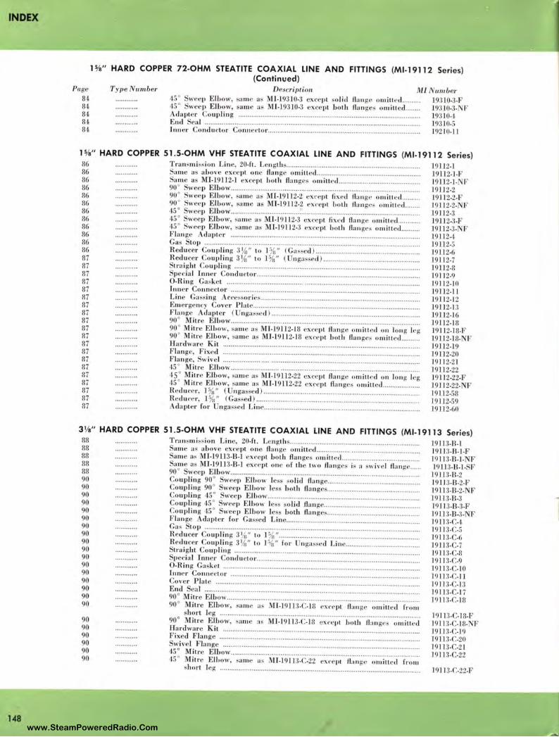
INDEX
148
Page
84 84 84 84 84
11/s" HARD COPPER 72-OHM STEATITE COAXIAL LINE AND FITTINGS (Ml-19112 Series) (Continued)
T ype umber Description Ml 45 ° we p E lb ow, sa me as MI-19310-3 exc ·pl o lid flan g 0111iu ccl .... ..... . 45 ° weep Elbow, ame ns MI-19310-3 exce pt boLh flan ges 0111iL1 cl .. ..... .
dapte r Co upling ....... ....... ........ .... .. ... ....... ................. ......................................... . . E ncl eal ..... ... ... .. ............. ... ....... .... ......... ... ..... .... ... ............... ...... ... .. ................. .. ...... . Inn er Conclu1·Lor Co nr re,·lo r .. ................... ... .. ................. .. .... ... ....... .. ... .. .......... .. ... .
11111/Jer 19310-3-F 19:310-3- F 19310-1. 19310-5 19210-ll
P/a" HARD COPPER 51.5-OHM VHF STEATITE COAXIAL LINE AND FITTINGS (Ml-19112 Series) 86 86 86 86 86 86 86 86 86 86 86 86 87 87 87 87 87 87 87 87 87 87 87 87 87 87 87 87 87 87 87 87
Trammi ss ion L in ·, 20-ft. L 11 gths .. ............. .... .......... .. .... ........... ...... ..... .. ..... ... .... . ame as aLove except o ne Aang omilled ........ ........... .. ... ..... ......... .... ............. .
Same a Ml-191.l2-l except holl, fl a ng omiued ........ .. .......... ... ...... ..... ........ . 90 ° weep Elbow .... .............. ..... ....... ...... .... ... ................. .. .. .... ........ ..... .. .................. . 90 ° wee p E lbow, sam • as 1-19112-2 ' ·rnpl fi xerl flan ge om i11 cd ...... ... . 90 ° Sweep E l Low, same a Ml-19112-2 exe •pl bo1h fl a nges 0111i1Lccl ....... . 45 ° weep E lbow .. .......... ....... ..... ...... .... .... .......... ................ •······················ ····· ·········· 45 ° weep Elbow, "am • as Ml-1911 2-3 ext·epl fixed fl a ng • o milled ..... .... .. . 45 ° Sweep Elbow, sam e n M I-] 9112-3 c ·ce pL hoth flan ges 011,illetl. .. ...... . F la rr g · claple1· ... ....... .. .... .. ... ............... ....... .. ... ...... ................... ... .... ..... .. ... .......... . . Ga Lop ...... .. .......... ... ................ ... ....... .................... .. ....... ...... .............. .... ............... . R educer Co uplin g 3 1/,1" Lo l %" (Gas ·eel ) .............. ........ ..... ............. ............... . Redu ce1· Co uplin g 3 1/u" lo 1%" ( nga ed ) .... .. .......... ........... ....... ......... ........ . . Lra ight Co upli11 g ......... .... ...... ...... ....................... ....... .. ... .......................... ............. . Special Irmer 0 11 d uc1or .. ........... .... ..... .. ............ .. ................ ..... ... .. ... ... .. ........ .. ..... . O-Ring Ga ket .... ...... .. ....... .. ..... ... .. ... ........ ... .. .... .. .................... ...... .... ... ..... .... ...... . . l1111 cr Co nnector ...... ... ......... ..... .............. ...... ..... ... .. .. .. .... ... .... ....... ................... ..... .. . Lin · Ga ss in g . c.-c~ o ries ..... .... ....... ...... ... ................................................ ....... ..... . E mer ge ncy Cover Plate ...... ............ ...................... ..... ......... ... ....... ....... .... ........... ... . Flan ge daple r ( ngasscd ) ... ...... ..... .... ..... .. .. ................... .. .... .... .... .... ........ ....... . 90 ° Mitre E lbow .... .... ........ ..... .. ..... .. ......... ............. ... ........ ........ .......... .. ....... .. ........ . 90 ° Mitre E lbow, sam e as M f-19112-18 xeepl flan ge omillctl 0 11 lo ng leg 90 ° M itre EJLow, ame a · MI-19112-18 exl'e pL b oth flan ges o miuecl ......... . Hardware Kil ............... .. ... ....... ..... ... ......... .. ...... .. ........... .. ................ ........... ....... .. .. . Flange, Fixed ................... ...... ........ ..... .. ...................... .. ..... ......... ........................... . F lan ge, wive[ .............. .... ....... ...... .. ..... ............ ...... .. ... .... ..... ......... ... ..................... . 45 ° Mitr E lbow ... ...... ... ... ............ ........... ......... ........... ........ ............ ....... ........... .. .. . 45 ° Mitre E lbow, same a · MI-19112-22 exc ·pl flan ge omiu ·cl on long leg 45 ° Milr E lbow, a111 e a MI-19112-22 exc pl fl a nges omiltecl ................... . Redu ce r, 1%" (Ungas eel ) ..................... ......................................... ....... ........ ...... . R eduee r, 1%" (Ga ssed ) .... .. ............ ............. ...... ...... ............ ..... .... ...................... . .
clapl cr for nga s. cd L inc ................. .... ................... ...... ..... .. .... ....... ... ........ ........ .
19112-1 19ll2-l-F 19112-1-1 F 19112-2 19112-2-F 1911 2-2-N f 19112-3 19112-3-F 19112-3-N F ]9112-1 19112-5 19112-6 19112-7 19112-8 1911 2-9 191 12- IO 19ll2-l 1 19112-12 19112-1:l 19112-16 19112-18 19112-18-F 1.911 2-18- F J 9112-19 19112-20 l 9112-21 ]91]2-22 19 112-22-F 19112-22- J, 19] 12-58 ]9112-59 19]] 2-60
3 1/a" HARD COPPER 51. 5-OHM VHF STEATITE COAXIAL LINE AN D FITTINGS (Ml-19113 Series) 88 88 88 !!8 88 90 90 90 90 90 90 90 90 90 90 90 90 90 90 90 90 90
90 90 90 90 90 90
Tra nsmi ss ion Lin , 20-ft. L ngths ... ..... .... ..... .. .. ........................ ...... .. ..... ........... . ame a above cxccpl one Aa nge omiLLed ............. ... ... ... ............. ........... ... ... .. . am e a~ MJ-19ll 3-B-l e cept both fl a nges orn ill ed ........ .. ........ .. .................. ... . am e a MI-19113-B-l exce pt one of 1bc two llange is a wivc l flan ge .. ... .
90 ° weep E lbow ........ ...... ...... ... .. .. .......... ............... ..... ... ......... ........... .. ..... .... ........ .. . Co uplin g 90° weep Elbow lcs so lid flan ge .............. .. .. .. ..... ............. .. .... .... . . Coupling 90 ° weep E lbow less boLb flan ge ............. .. .............. ... ... .. ..... ... .. .. . Coupling 45 ° weep Elbow ......... ........... ... ....... .... ... ...... ...... ............. ...... ............. . Co uplin g 45 ° weep E luow less olid flan ge ...... ... ......... ....... .. ........ ..... ........... . Co uplin g 45 ° wee p E lbow le both flan ges ............. .. .............. .... ..... .. ......... . Flange cla p! r for Gassed Linc ........ .. ......... .. ........ ..... .. .. ...... .... ....... ....... ....... .. . Ga s Lop ...... ....................... ...................... .......... .. ...... ...... ... .... ................... .............. . Reducer Co uplin g 31/ii" to] %" .................. .. ... ............... ... ... ..... ... .. ... ............... ... . R edu c r ouplin g 31/ti" to 1%" for nga ·ed Linc .............. ..... .. .................. . SLrai ghL ou1Jl i11 g .... ........................................................................................ ....... .
Ilec ial Inn r Co ndu ctor .......... ..... ..... ............ ........................... .............. .. ........ .... . O-Ring Ga sket .. ......... .. ............... ....... .... ............................ ..... ....... .... .. .. ................. . . J,,ne r Conn cclor ......... .. .......... ............. .. .. .... .... .. .... .. ..... .. ....... ... ............ .... ...... .... .... . Cover Plate ..... .. ...................... ...... ......................... ... ...... .......... ................... .. ...... .. . . End ea] ......... ..... ... ... ... ... ....... .. ............... .. ......... .. ............... ........ .. ........... ......... ....... . 90 ° M iLre Elbow ......... .... .... ....... ............... .. ........ ................. ... ..... ....................... .... .. . 90 ° M itre E lbow, sa n, • as MI-19113-C-18 cx.-e pl flan ge om ill , cJ from
hort l eg ....... ... ........ ... .. .. ............. ... ....... .. ... ....... ... ..... .. ................. ... ........... ...... . 90° Mitre El bow, m mc a Ml-1 9.ll3-C-18 ex1· ·pl both fl a nge omilletl Hardware K it ... ... ................... .... ............... ..... .. ......... ........... ............... .............. ... .. . Fixed F lange ...... ... .. ........ ...... ... .. .. ... ........ ....... ....... .. ............. .......... .... ........ .. ........... .
wive! Flange ......... ... ... ..... .. ... .... .................... ...... ... .. ............... ...................... ..... .. . . 45 ° M itre Elbow ........ .. ........ ... ..... .......... ... ........ .... .... .. ..... .............. .. ... ............. .... ... . 45 ° M ilr E ll,ow, same as M l-19 113-C:-22 ex,·cpl flan g • omitted from
shorl leg ................................ ................................ ................ .. .................. ....... .
1911 3-B-l l9II:!-B-l-F 1911 3-B-l- F 19l.1 3- B-l- F
191U-B-2 1911 :1-B-2-F 19113- 8 -2- F 19113-B-3 1911 3-B-3-F ·19113.13.3. I· 1911 3-C-4 1911:3- .-5 19113-C-li 1911 3-C-7 19113-C-ll 191J:l-C-9 1911 3-C-l0 1911:1-C-ll ]9113- -13 19113-C-l 7 1911 3- .-111
l 91 I:1-C-111-F 191 J:l-C-111- F 191] 3-C-19 19ll3- .-20 19113-C-21 19113-C-22
1911 3-C-22-F
..,
www.SteamPoweredRadio.Com
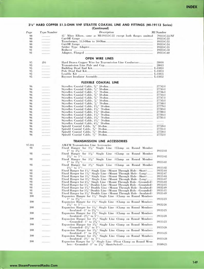
3 1/s" HARD COPPER 51.5-OHM VHF STEATITE COAXIAL LINE AND FITTINGS (Ml-19113 Series) (Continued)
l'agl' 90 90 90 90 90 91 91
9!i 95 95 95 95 95
96 96 96 96 96 96 96 96 96 96 96 96 96 96 96 96 96 96
97-10 i 98
98
98
98
98 98 911 911 98 911 98 98 98 JOO
100
100
100
JOO
JOO
100
100
100
T y pe umber
# 6
D scriJ)ti on M L nmber 45 ° Mitre E ll ww, , am · as M f-19Jl2-C-22 cxl'e pL lwth flan ge~ 0111i1ted
uL-Off Ga uge .. .. .. .... .... .. .. ....... ........ ... .......... ...... .......... ............ .... .. .. ... .. .. .. ... .. .. ....... . Transform er, 51.5-Ohm Lo 50-Ohm ...... .... .. ...... ... ... ............. .......... ... .... .. ... ......... . . Cu t-Off Gauge .... ..... ... ...... .... ........ ........ .................... ..... ....... .................... .... .... .... ... .
o ld er Type AdapLcr ........ .. ..... ....... ............ ... .. ........ .. ................. ... ......... .. ........ ..... . Reducer ....... ......... ............ ................. .. .. ..... .. .... ..... .................. .. .......... .......... ......... .
dapLcr, Flan ged ..... ................. .... .. .... .. ....... ........ .. ....... .... .. ...... .. ..... . ...... ..... .. .. .... . .
OPEN WIRE LINES Hard Dr"' 11 Co pper ~ ir ' for Tnu1, 111is, io11 Li11,• Cu11tl 11,·1or, ........ .. ......... . Transmi ssion Line Pole and Cn p .. ........ ..... .. .... .. ..... .. ...... .. .. .. .... .. .......... .. ........... . Building Dead Encl Kit.. ..... .. .... ... ......... ... ..... ...... ............. .. .................................. .. Pol e Dea,l Encl Kit. ........................ ... .. ....... .. ... ..... ......... ...... ...... .. .. .... ...... ............ ... . Lca d-J II K iL .... .... .. .... .. ...... .. ........ ...................................... .... ............................... .... . Ba yo11eL Insulat or ss mbl y ...... ........ ..... ......... .... ... .... .. ..... .. ............................ .. ... .
FLEXIBLE COAXIAL LINE Styroflcx Coaxial Ca bl e, %" 50-ohni. ....... .. .. .. .. .. .. .. .................. .. ... .. .. ... .. .. .... .... . . SLyroA ex Coax ia l Cah le, 1/2" 50-obm ... ... .... .. .. ......... .... ....... .. .... .. ................. .. .. .. . Styro fl ex Coaxial Ca bl e, ½" 70-ohm ...... .... ... .. .......... .. ... .. .. .. .. .... .. ...... .............. .. Styroflex Coaxia l Ca bl e, ¾" 50-ohm .................. .. ............ ... ............. .. .. ...... .. ..... . Styroflex Coaxial Ca hi e, ¾" 70-ohm .. ..................... .. .. .... ... ... ...... .. ......... .. ... ..... .. Styro A ··x oaxial Ca bl e, ½1" 50-o hm .. .. ........ .... ....... .. ..... ..... .... ... .. ....... ....... .. .... .. Styro Aex Coaxia l Ca bl e, ¾1" 70-ohm ... ....... .. ........... ... .. ... ................ .. .. ... ........ ... .
tyro fl ex Coax ial Ca bl e, l 1/,1" 50-ohni. ...... ........ ... .. .... .. .... .. .... .. ............ .. ........... . tyro fl ex Coaxial Ca bl e, l 1/,1" 70-ohm .................................................... .......... .. Lyro fl ex Coaxial Ca ble, 1%" 50-o hm ................. ... ............................ .. ............. . LyroA x Coaxial Cab le, l"{i" 70-ohm ........................ ....... ... .. ........ .. .. .. .... ........ . . tyroflex Coaxial Ca hl e, 31/,i" 70-ohm ................ .................. ..... ............... .. ....... . Lyrofl ex Coa ·ial Ca hle, 31/,i" 70-ohrn ........................ .. ... ................ ................. . LyroAex Coaxial Ca bl e, 6 1/,1" 50-oh111 ...... .. .......... ... ....... ... .......... ................. .... ..
Sp irafil Coax ial Ca hl e, ¾" 50-ohm ... .. .. ......... .......... .. .. .. ..................... .. .. ....... .. .. pirafil Coax ia l Ca hl e, 3/ii" 70-ohm .................. .. .............. ................................ ..
Spinofil Coaxial Cahl e, ½" 50-ohm ....... ... ........... ................ ......... .. .... .... ..... ...... . .·1lirafil Coaxial Cabl e, ½" 70-o hm ........ .. ..... ......... ... .......... .. ..... ..... ... .......... .... ..
TRANSMISSION LINE ACCESSORIES M-FM Tran smi sio11 Linc cce sori e
Fixed I:lanf.(er for 1%" ingle L ine ( C lamp 0 11 Round Memlwr l " to 2 ¼") .. ........................ .. ...................... ... ........................... .. .............. ...... ..
Fixed Han ger for 1%" . in glc Line ( la mp 011 Ro und Mc ml,cr 2½" lo 5") ........ .. ..... .... ............ .. ... ............... ........... .. ....................... .. .. ... .. ..... .. .
Fixed Han ger for 3¼" in gle Linc (C la111p on Round Membe r ] " Lo 2¼") .... .... ... ..... ..... ........ ...... ...................... ... .... ....... .................. ... .. ...... .. ..
Fixed Han ger for 31/,i" i11 glc Line (C lamp on R o und Membe r 2 ½" lo 5") .......................... ........ ........ .. .................... .. ... ... ... ..... .... ......... ... .. ..... .
Fixed Han ger for 1%" in gl Li ne (Mount T h ro ugh Hol e- horl ) .. .. ... . Fixed l-la ng· r for J %" Sin gle Linc (Mo unt Through Hol e- Long ) ... .. .. . Fix ed l-l a nger for 3¼" ingl Linc ( oun t T hrougl , Ho) horl ) .. ... .. . F ixeil Han g' r for 31/,:" ingl c Lin e (Mount Through Hol e- Long <.. .... .. F ixed Han ge r for 61/,i" Sin gle Lin c ( Moun t T hrough Ho le- Grounded ) Fixed Han ger for 1%" Do uhl e Lin e (Mo u111 Throu gh Hol e- Gro und ed ) Fixed Han ger for 1%" Double Line (Mount Throu gh Ho l In ulatecl ) Fixed Han ger for 31/,1" Doubl e Line (Mount Through Hol Gro unclecl ) Fixed Han ge r for 31/ii" Do ub )(- Lin e (MounL T hrough Hol e- 1rn-ulal ed ) Expansion Han ger for I %" S in g] Lin c (Clamp 0 11 Ro und Mem hers
] " 10 2¼") ............. .. ......... .. .................................. .. .............................. .. ......... . Expansion Han ger for l o/,," . i11 gle Lin e ( Clamp 0 11 R ou111l Mcmhcrs
2½" lo 5") .. ...... ..... ... ........ .. .... .. ..... ..... ... .. ......... ......... .. .... ..... ................... .. .. .. . .. Ex pa nsion Hanger for 1%" in gle Linc (Cla mp 011 R o und Mcmhcrs
- 1'11 , ulated- l " 10 2¼") ....... ........ ... ........ .. .. .... ....... .. ............ ...... ... .... .... ....... . Expans ion Hanger for 1%" i11 gle Lin e (Clamp o n Round Mem hcrs
- l11 sula1 ecl- 2½ " lo 5") .................... ...... .. .... ....... .. .. ... ... ... ............. ..... .. .. .. .. .. Expansion Hange r for 31/ii" ingl e Linc Clamp o n Round Members
- Grounded- I " lo 2 ¼") ............................... ..... ....... ......... .. ............... .. .. .... . Ex pansion Han~e r for 31/,i" , ingl e Line C lamp on Round Membe rs
- Grounded -2½" to 5") ................................................... .... .......... .... .. .. ... .. Expan sion E:l.m gcr for 31/:i" Si ngle Line C lamp o n Round Members
--Insulated J" lo 2¼" ) ..... .......................... .. ........... ...... ... .. ....... .. .. .. ........ .. Expa nsion Han ge r for :31/,1" • in gle Lin Clamp o n Round Memher,
- l n, ul a tc,l- 2½" 10 5") .............................................. ... .................... .. ... .. . Expamion Han ger for ¾" S ingl e Li ne ( Pivot Clamp on Round Mem-
bers- G round ed- I " lo 2 1/4" 'hort- 1 ivell .................. .. ...... .. ............... .
79 1 I:l-C-22- ' F 19113-C-51 19 11 3-C-53 19113-C-54 19113-C-55 19113-C-58 19113-C-60
28010 21101 3
L-13115:1 f..J :!115 1 L-t:rns5 L-13852
277 12-1 2774:l-l 27746- 1 27744- 1 27H7-l 27745-1 27748-1 27779- 1 277113-1 277110-1 277114-1 277111-l
27749-.l 2775 1-1 27750-1 27752-1
1911 2- n
19Jl2-12
19113-41
19 11 3-12 J9ll 2-H 19112-117 J91H-H 1911 3- 17 J9:!l4-H 1911 2-15 1911 2-49 1911:1-1 5 1911 349
19 '1 ] 2-23
J9ll2-26
1911 2-25
191 12-28
1911 :1.2:1
19113-26
J9U:l -25
]9JH-28
19309-23
INDEX
149 www.SteamPoweredRadio.Com
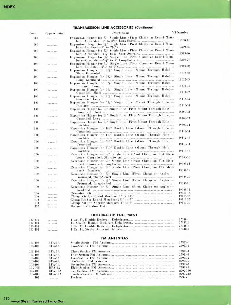
IND!X
150
/'r,g('
100
]()0
JOO
100
100
100
JOO
100
100
100
JOO
100
100
JOO
JOO
100
100
100
100
100
10()
100
JOO
JOO
100 100 JOO 100 102
10:1.101. 10:1.JOi ]03.1 0 i 10:3.10 i
111:,.JOH 105.108
J05.l(JH ]05.)08 J05. J08 105-108 105-1011 105-lOR JOS.JOII 105. J OR
107
T y 11 e 11111/Jer
BFA-1 BF ·2
flF BF flF BF BF .7 BF -8 BF A.JOA BFA.12
TRANSMISSION LINE ACCESSORIES (Continued)
Description MI
Ex pan sion II a nge r for ½i" in gle Linc ( Pivot C lamp 0 11 Round 1cm• ltc rs Groun<le cl l " to 2¼" Lon g• wivc l ) ... .. ...... .. ................................ .
Ex pa nsion llan i;c r fo r ½i" i11 gle Lin · ( Pi vo t C lamp 011 Rou1ul M em• bcrs ln sulatecl- l " to 2¼" ) ..................... ........ .... .......... ..... ....... ... .. ... .... ... . .
Expan sion Han ge r fo r ¼" in g le Line ( Pi vo t C lamp 0 11 R ound M e 111• l, c rs Gro unded 2¼" l o 5" hor t•Swive l ) .. .... .. .................... .... ... .. ........ .
Ex pa11 , io 11 Han ger for ½i" in g le Lin e ( Pivot C la mp or R o und Mem· bcr" Grounded- 2 ¼" to 5" Lon g.Swive l ) ...... .. ........ .. .......................... ..
Expa 11;. iu 11 H ange r fo r ½1" . in g lc Lin c ( Pi vo t C lamp or Ro und Me111-l, cn-- l11 sulatcd 2¼" to 5") .................. .... .......... .... .............. .. ........ .... ....... .
Ex pansi on Han g r for F½'1" in gl Lin e ( Mo unt T h rough H o l •) -Short, Gro und ed ..... ....... .. ........... .......... .... ...................... ................ .. .. ... ......... .
Expa ns ion Han ge r fo r 1%" in gl Linc ( Mo unt Throu gh H ole) -Lon g, Grounde d .... ..................... .... ....... .. .. ..... ... ...................... ... ................. ... .
Expa ns ion Han ge r for P (1" ing le Line ( Mount T hro ugh Holc ) -ln sula tcd , Lo n g ............... ... .. .... ... ... .... .... .. ... ...... ............. .. ... ... ........ ....... .... .... .
Expansion Ha nger for 3 1/,i" in gle Lin e ( Mo unt Thro u gh Hol e) G ro und ,d , ho rt .... .. .. ... ... .... .. .... .. ..... ......... .. .. ...... .. ....... .... .... .. ...... .. ... .......... .
Expa nsion H a nge r for 3 1/,1 ' • i11 gle Lin c ( Mount Throu gh H o le) ro und ed, Lon g .... .... ..... ... .. ... .. .... ........... ......... .. ...... .... ......... .. .. ...... ........... .. .. .
Expa nsion Han g r for :11/,1" Si ngle Lin e (Mount Throu gh Hol e ) Jn ;, ulate<l ....... ...... ... ..... ..... .. ......... ....... .......... .. .. ... .. ... .... ... ....... ... .. .................... .
Ex pan, ion Han ger fo r 1/:i'' ·ing l Linc ( Pi vo t Mo unt T hro ugh 1-lol · ) G round d , hort ... ... .... .................. ... ... .... .... ...... .. .. ........ ...... ....... ... ........ .. .... ..
Expa nsio n l·ltu1 gc r for ½:" Sin g I Line ( Pi vo t Mou nt Through ll ol •) Gro und ed, Lon g .... ... .. ....... .... ..... ... .. .. .. .... ........... ........... ... ..... .. .. ........ ...... ....... .
Expa ns io n Han ger fo r 1/,1" S in g le Linc ( Pivot Mount Through H ole ) -J11 sul atcd ..... ..... ..... .. .......... .... ......... .. ....... .............. ........ ..... ........... .... ... .... ...... . .
Expa nsion Han ger for l % " Do ubl e Lin e ( Mount Thron i; h 1-l o l ' ) G rou nd ed .. ... .... ....... ...... ..... .... .... ... .. ......... .. .. ....... ... .... ...... ... ............ ... .. ... ........ .
Ex pa nsio n Han ge r for l ¾" Oouhl e Lin e ( Mount Throu i;h Hole ) Insulat ed .... ..... ................ ....... ...... ...... ... ......... ....... ......... .... ...... .. .. .... ... .... ........ .
Ex pan sio n H ::i nger fo r 3¼" Oouhl e Lin e ( Mo unt T hrou gh Hol e) G 1·o u11d cd ....................... .. ............ ...................... ... .... .. .... ...... .. .. ... ... .......... ... .. ..
Ex pan sio n Han ge r for 3 1/,i" Oo ultl e Lin e ( Mo unt Thro u gh H o le) Jnsul .1t cd .... .. ............. .............. .. .. ........... ... ... ........ .... ..... .... ... ..... ...... ..... .... ........ . .
Ex pansi on Han ge r fo r ½i" in glc Lin c ( Pi vo t C la11q1 011 Fla t c111• bers) - Gro unded, ·hort• wiv I ... .. ..... .... .. ...... .... .. ....... .... .... ... .. ................. .
Ex pami o n Han g r for 1/i;" in g le Linc ( P ivot C lamp 0 11 Flat M c 111 -l, crs ) - G round , c] , Lon g• wivcl .... ............. .. ...... ........... ........ ................ .... . .
Expansi on Ha n g r for ½1" ~in gl Line ( Pi vo t C lamp ,, 11 Flat M.cn1• be r,) - Jnsul ::i ted ... ... .. .... .. .... .. ...... ........ ...... ......... ........... .... ....... ... ......... .. .. ... . .
Ex pa 11 i, ion Hang r for ½:" i11 gle Linc ( Pi vo t C lam p 0 11 ngl •,) Gro und ed, ho rt• wive I ...... ........ ... ................. ............ ........ ..... ..... ... ... .. ... .. .. .
Ex p,111 ion Hanger fo r 3/n" in g le Lin • ( Pi vo t C la111p 0 11 Angle ,;) Gro undc ,1 , Lon g- wi vc l ........... ...... ... .... .. ... ... .......... ............ .. ..... ..... .. .. ........ . .
Ex pansion Ban g r for ½1" in glc Linc ( Pi vot lamp 0 11 ng le;,) Tn sulat ecl ... .... ... .. ... ................ .. .. ....... ..... .. ........ ........ ... ............... ........... .. ......... .
Extcn~ion Kit ...... ....... .. ....... ............................ .............. .. ..... ... .......... ... ... .. .. .... .. ..... . C la mp Kit for Rou11.J M mbers l " to 21/4" . ........... .. ... ...... .. ........... .. ........ .. .. . Cla mp it for Round Je111bc r, 2½" to 5" ... .. .... ... ....... .......... .. .. ..... .. ........ .... . . C la mp Kit for An gular Me mbe r , I " to 8" .................. .. ........... .... ... .. .... .. ... ... . . llan g •1· l11 sta ll atio 11 Data
DEHYDRATOR EQUIPMENT 1 Cu. Ft. Doubl e Dc. in ·a11t Deh ydrator .... ..... ... ...... ... ..... ........ .. .... ..... .............. . l 5 Cu . Ft. Do uhl Dcs ic·c·ant Deh ydrator ............... ........ ...... ....... ................... . 2 C u. Ft. Doul,l e Desi .. c·a nt Oe hy,lrator ............. .. ..... ... .. .. .. ... ... ... .......... ... .. ..... . l Cu. Ft. S in gle Dcsil'n111t De hydrator ..... ... .... ... .... ...... .... .. ... .. ........................ .
FM ANTENNAS S in gle Sct· tion FM Ante nna ............ .. ........... .. ... ............ .. ......... ... ..... .... ... .... .... ..... . Two• et· t ion F nt cnna ....... ... ...... ............ ....... .. ........ ... ... ... .... ..... ...... .......... .. ... .
T hrc•e• edion FM nlc nna ............ .... ........ ... ....... ... ..... ........ .. ........ .. ... ......... ........ . . Four• ecti o n FM ntc 11m1. ...... .. ...... .. ...... .... ... .......... ... .... ...... ..... .... ........ ....... .... .. . . Five• Pct ion FM nt ·1111:1 ............. .. ..... .... ... ... .. .. ... .. ...... ........ ....... .. ... .... ... .. .......... .
ix- ecti on FM A nt e 11 1H1 .... ........ ... ..... ..... ....... ..... ..... ... ...... .... ... .. .. .. ................ ...... . . even- ecti on FM nte nna ........ ... .. ... .......... .... ....... ... .. ....... ..... .. .... .. ....... ........ ..... . .
E ight • cti on FM ntenna .. ...... ...... ............ .. ...... ............................. .................... . T ·11- ecti on FM nt enna .. ..... ....... .... .... .. ....... ... ........ .... .. .... .. ... .... ........ ....... .. .... ... . Twe lve• cti on FM ntc ,111:1 .. ....... ... ........ ........... .. ...... .... ........ .... ........... .. ...... .. .... . De-Jeer. ...... ....... .. ............. .. ... ... .......... .... .. ......... ..... ................ ...... ..... .... .... ...... .. .... .. .
11111/Jer
19309-2 i
19309.25
19309•26
19309-27
19309•28
19112-32
19112.:n
l9U2·H
1911 3.:32
191 13-3:!
19113•3 I
I 9;309.:12
19309.3:l
19309.3 1
1911 2.M
19112· 18
19 11 3.11,
1911 :1.18
19:H)'J.20
19:rn9.21
19309-22
19309•29
19309.30
19:309.31 191H-16 19 JJ:1.56 19 11 :3.57 1911 :3.59
27:IJR. I 27:1 18·2 27:1411•:l 27'.IIR• I•
27')2:,. J 27925•2
21925.3 27925.1 27925•5 27925-6 21925.7 27925•8 27925-10 27925•12 27926
www.SteamPoweredRadio.Com
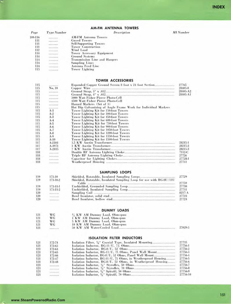
Page
109.]]6 111 111 ]11 11 2 114 114 11 ,i lH 114 11 5
115 115 115 n s Jl S 11 5 ]1 5 ]1 5 11 5 11 5 115 115 Jl 5 11 5 11 5 11 5 11 5 ]1 5 11 7 117 11 7 118 ll 8 11 8 11 8
119 ll 9
]19 11 9 120 120 120
121 121 12 1 121 121
121 121 121 121 121 121 121 121 121 121 121
T y pe 11111ber
ro. lO
·l .2 .3 .,~ .5 -6 .7 -8 .9 .JO -2101 -1 971 -2815
173-10 173-10-2
l 73-11-1 173-11 -2
WG G
'\ G ' G
172-74 172-63 172-61 172-65 172-66 17247 172- 18
AM-FM ANTENNA TOWERS Descriptio11
M-FM nle nna T owe rs
M l 111111b Pr
uyecl Tower elf. up portin g T owers
Towe r Construe-I io n \ ind Load Towe r cce sory Eq uipme nt G ro und ystem Transmiss ion Lin e and Han g,•rs
amplin g L ines A ntenna Fee,! Li nP To, "r Lii:ht ing
TOWER ACCESSORIES Ex(lanclecl op per round . nc n 8 foot x 2 I fool . e<'li o n ......................... . Co pper \Vire ...................................................................... .................................. .. ,. Gr ounJ trap 3" x .032 .............. .... ................... .. ................ ................................. .. Gro und trap, 4" x .032 .... .... ......... ... .. ... ... ... ... .. ................... ............................ ..... .. :IOOO \ a tl Fishe r Pie n ·e Photo•Ct' ll 1500 Wa ll Fisher Pi erce Ph oto•C{' ll Ha zard Marker ( el o f 3) H ot Dip Ga lva nizin g of ngl Fr.1m e Work for J1uli v id11 a l Mark ers Towe r Lighting Kit for 150-foot To\\t'r To, e r Li ghtin g Kit for 300-fo ol Tuwt•rs To, e r L ighting Kit for 450-foot To, e rs Tower Lig hting Kit for 600-foo t T owers Towe r Li ghtin g Kil for 750-foot T owers Tower Li ghtin g Kit for 900-fool Towe r Tower Li gl1tin g Kit for 1050-fool T ow(•r -: Tow •r Li ghtin g Kit for 1200-foot Towe r Tow•r Lightin g Kil for 1350-foot Towers Tower Li ghtin g Kit for 1500-fool T owers 1.5 K. , · ustin Tra nsform er ........... ... ..... ...... ....................................... ... ... .... ... ... .. 3 K, ustin Transform er ........ .......................... .. .................... .. ................. ... ... . .. 7 K'\ ust in Trn n · form er ........................ ... ....................................................... .. Doubl e RF A nt nna Li ghtin g Choke .......... .... ............................... .. .... ... .... ...... .. Tr iple RI• nt cnna Li ghting Choke .................. .. .. ....... .. .......... ...... ................... . Capa,· itor for Li ghtin g Chokes ................................................................ , .......... . \ ra lhc rproo f Housin , .................... .. ...................... ..... ..... ......... ....... ........ .......... . .
SAMPLING LOOPS lii c lded, R otatahle, Insulated amplin g Loops ...................................... .... .. .. hi lcled, Rotatabl , ln sulatecl amp li ng Loop for us with RG-8 / 11
ab le ... ...... ... ............... .................... .. ......... ................................. .................. .... . U nshicld e<l , Grou nd ·cl a mplin g Loo p ........ .. ...... .. .. .. .... .... ..... .. ...... .................. .
n shi e lJ cl , In ulat cl amplin g Loo p .. ...... ...... ........ ....................................... . am piin g Co il .... .... .... ... ...... .......... .. .................. ............... .... ............................ ...... ..
B owl [11sula1or, so li cl stu<l .... ..... ........ .................... ..... ....... ... ................. ..... ........... . Bo, I Insul ator, ho ll ow tud ...................................................... .. .... .. ................... .
DUMMY LOADS ½ K'\ M Dumm Load, Ohm-spun 1 K, AM Dumm y Load , Ohm-,pun 5 K \ ' AM Dumm y Load Oln11-,; pu11 10 KW Dumm y Loa,1, Ohm-sp un
27765 28405-8 28405-A2 28405- l
28215-1 2821 S-2 28215-3 7112-C 27726 27728- l 27741
27729
27759 27730 277:l l 8217" \ 27723 27724
50 K\V AM \ a ter-Coo le,I Load ................................. ......... ............. ...... ............. 27029-3
ISOLATION FILTER INDUCTORS I so lation Filter , ¾" oax ial Type, Insulat ed Mo uutin g .......... .................. .. I solat ion Tndu,·tor, R G-11 / , 75 Ohms .......................................................... .. I so lati on Indu ctor, R G-8 / , 52 Ohm s .............. .... .................... .. .................... .. f ,olati on [ncl uctor, R G-JJ / , 75 Ohms, P ,rne l Wa ll Mou nt.. ...... .. ............ .. J olat ion Indu ctor, R .f', / , 52 h111 s, Panel 'I a ll Mo un t.. ........................ .. I so lati on Jnclut·tor, RG-11 / , 75 Ohm s, in ea th erproof H o usin g ...... .. .. .. 1,o lati ou J1ulut·tor , RG-8 / , 52 Ohm s in \ eatherproo f l-lou, ing ........ .. Iso lati on lnclu etor, %" , tyro flex, 50 O hm s .. .... .... ........................................... . I sol:i1 ion Jndu ,·tor, }(i" tyro flex, 70 Ohm ~ .......... .. ........................................ .. Iso lati on Indu ctor, 3/ii" p irafil , 50 Ohm s ......................................................... . l so l:11i on Tnclu ctor, 3/ii" p irali l, 70 Oh111 .. .. ................... ... .............................. ..
27735 27756-l 27756-2 27756-3 27756- i 27756-5 27756-6 27756-7 27756-8 27756-9 27756-10
INDEX
151 www.SteamPoweredRadio.Com
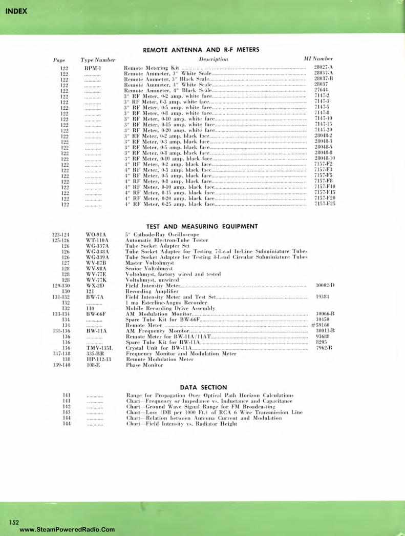
INDEX
152
Page
122 122 ·122 122 122 122 122 122 122 122 122 122 122 122 122 122 122 122 122 122 122 122 122 122 122
12:1.1 2 1 12!;-1 2/i
12/i 126 126 127 1211 128 1211
129- 1:IO 130
131 -132 l:l2 132
1n 1:i 1 134 134
J:I S- 13/i J:16 J:16 l :!6
l:!7- 1:Hl J:1 11
1:19. 1 rn
111 I I I H 2 113 1'11 141
T y pe umber
BPM-1
110 BW-66F
B'\ -ll A
TM -13!; L 335-BR HP-11 2-H 1011-E
REMOTE ANTENNA AND R-F METERS
DescriJJlion Ml 11111ber
R c 111 01c Me te rin g Kil .......... .. ....... ........................................... ............................ .. Re 111 01 • A 111111 e1e r, 3" ~- hitc Sl'al e ... ................. .... ....... ..................... ... ... .. ......... . R emot e 111mcte r , 3" Bla l' k S,·al c ... ... ... ........ ....................................... .... ... ........ . R e111olc 111111 e1e r , I" White Sl'.ol e ... ... .. .. .. .... .......... .. ... ....................... .. .. ........... . R e mote 11111,e ler , 4" Bla,·k S,·al e ........................................................ .. .. ......... . :l" RF M ·le r, 0-2 a111p. "hil• fa ce ... .. ... ... .... ....... .. .... ................ ........ ... ...... ........ . 3" RF M •Ler 0-3 amp. "hi Le faee ....................................................................... . 3" RF c l ··r, 0-5 an1p . \\' l1it · fat·c ........... ................................ .. ....... ... .. ............ . '.J" RF Meler, 0-8 arup . ,\hit e face ....... ..... .. .... .... .. ...... ... ........ .. ... .. ...... ... .. ..... .... . . 3" RF e le r, 0-10 a mp. "hit •• fat' c .. .. .. ........ .. ............ ...... .. ............................... . ::I" RF M lc r, 0-15 amp. while f,11·,· ................................. ... ............................... . :J" RF i.-Lc r, 0-20 amp. "hi lc fa ce .. ....... ..... ........ ..... ............ .... .......... ... ........ .. .. :I" RF el<'r, 0-2 ,11111i. blad-. f:we ............. .. ................ ............................. ...... ..... . 3" RF M le r, 0-3 amp . bl ad, fa ee .......................... ............................................. . :1" RF Me te r 0-5 a mp. lil a ,·k fa ce ................................................... ................... .. 3" RF M ele r, 0-8 a111p. b!al' k fa ce .... ....................... ............................................ . :J" RF Meie r, 0-10 a111p . bl:11·k fal' e .............................................................. ...... .. J." RF 1e tc r 0-2 amp . bh11·k fa,·• ..... ... .... ................. ........................................ . 4" RF 1et -' r, 0-3 u111p . 1,lac_•k fa ce .... ..... ............ .... .......... ..... ........... ... ... ............ . I " RF M te r, 0-5 amp . l,la t· k fa ce ..................................................................... . t" HF Me te r, 0-8 arup. bl atk face ... .......... ... ..... , ..... .. ..... ............ .. ..... ............... . . 111 RF •l cr, 0-10 a1np. hl ac·k f:.u.-e .... .. ... ..... ... ......... ....... ... .. ... ... ... ............ ... ... . .. 4 11 RF' M eler, 0-1 5 a1np . bla t'k face ............ .. ....... .... ....... ...... .... ...... ...... ............ . . I" RF Mt•l t.' r, 0-20 arnp. bhu·k far e ............. ............ ................................. ........ .. ,t" HF MPl1 •r, 0-25 a111p. hla t· k fa ce ............... .... ................................................ .
TEST AND MEASURING EQUIPMENT 5" all, odc-Ra y O, ,·ill o,n,pc A ulomali · El clron-Tuhc T est r Tube od, cl claptc r ·L Tube Ol'ke l Acl npler for T esl i 11 g 7-f.l' :ul I 11 -Linc Suh111i11ialL11· • Tu hes Tub ock ··l Acbpl •r fnr T ,•s1i11 g 8- Leail Cirndar S11h111i11ia1ure Tul11•,
aste r Vo h o h111 y,1 • c ni o r oltobm ysl
o h o l1111 ys1, fa clo r y "irt•d a11d ll's lc1I oho l1111 y,1 unwired
Fi e ld J 111 c 11 s ily M ' I er ............................. ...................... ......................... ....... .. .... ... . R ccordi11 g 111plifi e r Fie ld ln1 c 11 , i1 y Mete r a11d T est el. .... ... .... ........... ........ ............... ................. ... ..
I ma Es1erli11 e• ngus R el'order M ohil e R e,·o rdin g Drive Asse mbl y
i odulati o n 1onil or ...... ....... ... .. .......................... ..... .. .. .. .... ........ ............ ..... .. pare Tuhc Kil for 13 ~ -66 F .. .. ........ ...... ...... .... ...... .. .............. .. .. ... ........ ...... ... .... ..
R e mote Mele r ......................................................................................................... . AM Frcc1uc111·y M onito r ........ ... .... ..... ... ............... .... ..... .. .. ............ ... ....... .. ........... .. R e11101c ele r for B ~· -11 /] l T ...... ................... ... ...... .. ... ... .. .... .. .............. .. ..... .
pure Tube Kil for B~ -11 ..... .. ....................... ................................. ... ............ .. r yslal nil fo r B W-11 ..................................................................................... .
Fr c1ue 11 cy Monitor a11d Modula1i o 11 M!'l!' r R e mol e Modula1io11 M,•1,•r Pha sf' Monilor
DAT A SECTION Ra11 gc for Propag:11i o 11 Ow r O pti ,·nl Path llori zo n Calt-ul a1i o 11 ,
harl Frequ enr) or J111ped :o m·e vs. lndu.-1 :11u·e a11tl .ap:11·ita11n• Chart- G round ~ ave igna l Ra11ge for FM Broadrnstin g C ha ri - Loss ( DB pe r 1000 F1. ) o f R C 6 Wire Tra11 s111i ss io11 Linc Char1- R c lalio11 be tween 11t c 111,a Currc111 a11cl Modula1i o 11 C hari Fie ld l11te 11 ~i1 y vs. Radiat or H e ight
28027-28037-A 28037-B 28037 276H 7117-2 711 7-:1 7117-5 7147-11 7147-IO 7117-1 S 7117-20 2801-8-2 28018-:1 2801 8-!; 28018-8 211018-10 7 I 57-F2 71!;7-F:I 71!;7-F!; 7157-F II 71!;7-FI0 71!;7-Fl !; 7l57-F20 71!;7-F25
:rnno2.n
I •):lll,1
30066-R :101!;0
# 59160 30011-B 93688 1129:, 7962-H
www.SteamPoweredRadio.Com
RCA
AM 2259
REGIONAL
OFFICES
Atlanta 3, Ga. 1121 Rhodes-Haverty Bldg., Jackson 4-7703
Boston 16, Mass. 200 Berkeley Street, Hubbard 2-1700
Camden 2, N. J. Front & Cooper Streets, Woodlawn 3-8000
Chicago 54, Ill. 1186 Merchandise Mort Plaza, Delaware 7-0700
Cleveland 15, Ohio 1600 Keith Bldg., Cherry 1-3450
Dallas 35, Texas 7901 Empire Freeway, Fleetwood 2-3911
Hollywood 28, Calif. 1560 N. Vine Street, Hollywood 9-2154
Kansas City 6, Mo. l 006 Grand Avenue, Harrison 1-6480
New York 20, N. Y. 36 W. 49th Street, Judson 6-3800
San Francisco 2, Calif. 420 Taylor Street, Ordway 3-8027
Seattle 4, Wash. . 2250 First Avenue, South, Main 2-8350
Washington 6, D. C. 1625 K Street, N. W., District 7-1260
RADIO CORPORATION OF AMERICA BROADCAST AND TELEVISION EQUIPMENT CAMDEN, NEW IERSEY
Tmk(s)®
•
www.SteamPoweredRadio.Com
wigfi
Stolen 2 Line Transparent
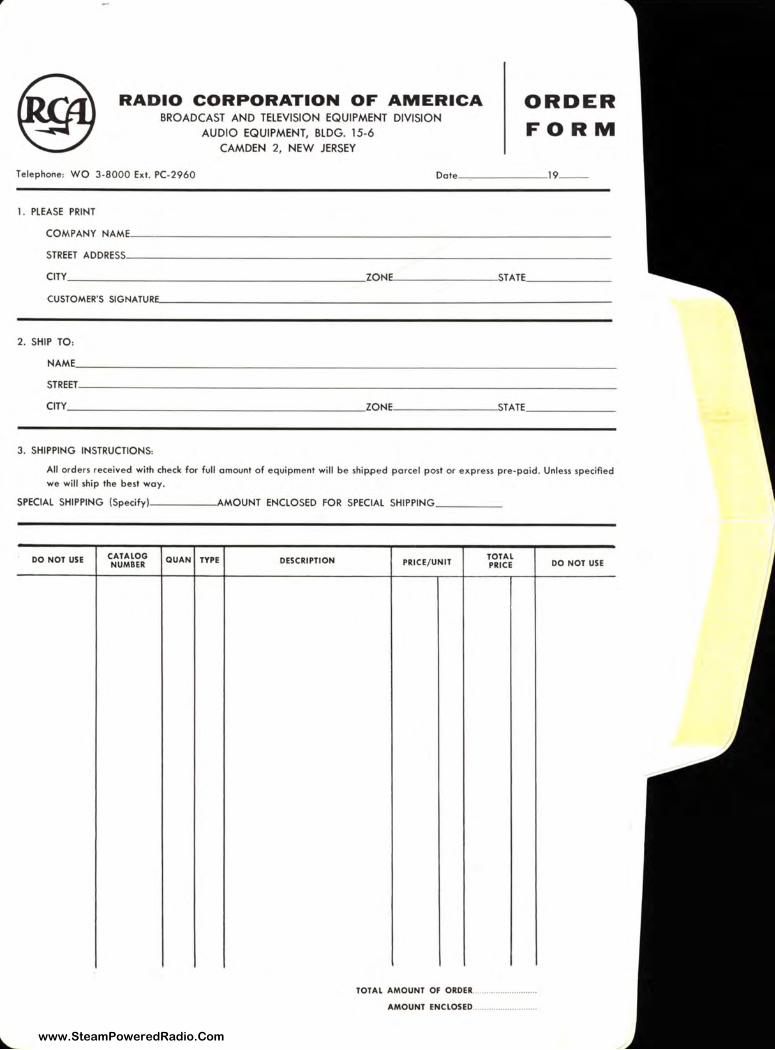
RADIO CORPORATION OF AMERICA BROADCAST AND TELEVISION EQUIPMENT DIVISION
ORDER FORM AUDIO EQUIPMENT, BLDG. 15-6
CAMDEN 2, NEW JERSEY
Tele phone: WO 3-8000 Ext. PC-2960 Date ______ 19 _ _
1. PLEASE PRINT
COMPANY NAME _________________________________ _
STREET ADDRESS ___________________________ _______ _
CITY _____________________ ZON ,.._ _______ STATE _____ _
CUSTOMER'S SIGNATUR"---------- --'---------------- -------
2. SHIP TO:
NAME ______________________________________ _ STREET _____________________________________ _
CITY _____________________ ZON,.._ _______ STATE _____ _
3. SHIPPING INSTRUCTIONS:
All ord ers received with check far full amount of equipment will be shippi,d parce l post or express pre-paid . Unless specifl ed we will ship the best way.
SPECIAL SHIPPING (Specifyl----~MOUNT ENCLOSED FOR SPECIAL SHIPPING ____ _
DO NOT USE CATALOG QUAN TYPE DESCRIPTION PRICE/ UNIT TOTAL
DO NOT USE NUMBER PRICE
TOTAL AMOUNT OF ORDER .......................... ..
AMOUNT ENCLOSED ........................... .
--!: ....
www.SteamPoweredRadio.Com
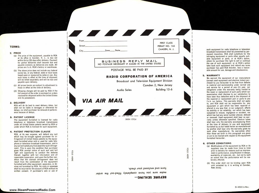
TERMS:
r. PRICE (a) The price of the equipment , payable to RCA
at its office in Camden , N. J ., is due net within thirty (30) days after delivery. Payment for partial deliveries shall become due and payable similarly as deliveries are made. All prices are f.o .b. RCA's factory or warehouse .
(b) The above price does not include any federal excise tax , or any federal , state or local taxes based upon or measured by sales or use. Any such taxes in effect at the time of shipment will be billed separately and will be due and payable upon delivery .
(c) All prices herein are subject to adjustment to those in effect at the time of delivery .
(d) Shipping charges will be paid by RCA if the full amount of the order is enclosed on orders received for shipment within the United States and its possessions .
2. DELIVERY RCA will do its best to meet delivery dates, but shall not be liable in damages or otherwise for delays, nor shall purchaser be relieved of performance because of delays.
3 . PATENT LICENSE The equipment furnished is licensed for radio telephone or television broadcast transmission under all United States patents owned by RCA or under which RCA is licensed for such equipment.
4. PATENT PROTECTION CLAUSE RCA , at its own expense, will defend any suit which may be brought against purchaser for infringement of United States patents by the equipment furn ished when sold or used for radio telephone or television broadcast transmission, and in any suit will satisfy any final award for such infringement. This is upon the condition that purchaser gives RCA prompt notice of such suit and tu II right and opportunity to conduct the defense thereof, together with full information and all reasonable cooperation , and upon the further condition that the claimed infringement does not result from the combination of the equipment furnished with other equipment , apparatus, or devices not furn ished by RCA . No costs or expenses shall be incurred for the account of RCA without its written consent. If purchaser' s sale or use of
:~~~~~~~ I~ From ~ FIRST CLASS
I Street PERMIT NO. 166
I City ______ ->one_Stote__ CAMDEN, N. J.
I
I~ Ill I BUSINESS REPLY MAIL I NO POSTAGE NECESSARY IF MAILED IN THE UNITED STATES
I P()ST AGE WIL -- .. ··- - . I . __ ,., __ .. __ L BE PAID BY
I ~ RADIO CORPORATION OF AMERICA ~ I Broadcast and Television Equipment Division
I Comden 2, New Jersey
: Audio Soles Building 15-6
! ~ VIA AIR MAIL ~
I I I I I ~-
~~~~~~~
0 5 ;:; "' m
3~3H 01O~
·,pa1p Jno.< pasopua puo WJO¾
JapJo a4i ino-pauy J.1aia1dwo:> aA04 no.< aJns allow
-ON11VlS lH0.:138
0 5 :,: m
"' m
such equipment for radio telephone or television broadcast transmission shall be prevented by permanent injunction , RCA shall substitute for the infringing equipment or parts other equally suitable equipment or parts, or at RCA's option, obtain for purchaser the right to sell or continue the use of such equipment, or at RCA's option take back such equipment and refund any sums purchaser has paid RCA therefor , less a reason able amount for use, damage and obsolescence .
5. WARRANTY We warrant the equipment of our manufacture (except used equipment and electron tubes) purchased by you hereunder to be free from defects in material and workmanship under normal use and service for a period of one (I) year, our obligations under this warranty being limited to the repair or replacement of such parts which our examination shall disclose to our satisfaction to have been thus defective and to the shipment of the repaired or replacement part or parts to you f .o.b. our factory . This warranty shall not apply to, and RCA shall not be responsible for , any equipment or part which has been repaired or altered in any way that , in our judgment, affects its stability or its reliability , nor which has been subjected to misuse, negligence or accident , nor which has had any serial number altered, defaced or removed . Used equipment shall bear no warranty unless otherwise specified. Electron tubes shall bear only the warranty accompanying them at the time of delivery to you and equipment furnished by us but listed herein as manufactured by another shall bear only the warranty given by such other manufacturer . No warranties other than those set forth in this paragraph are given or are to be implied with respect to the equipment furnished hereunder .
6. OTHER CONDITIONS (a) Modifications of the equipment by RCA or its
suppliers may be made from time to time prior to delivery for reasons such as improve· ment in performance, simplification in design, availability of materials, etc ., but not to such an extent that the performance will be mater ially affected.
(b) This order shall not be binding upon RCA until accepted by it in writing at Camden , New Jersey .
JJ--4022 A-Rev.
www.SteamPoweredRadio.Com

r------------------------------------1
PRICE LIST
-----------------FOR·----------------
AM-FM Transmitting
Equipment r--------------· _....._ --------------, I I I ,....._~ I I I I I I I I PRICES EFFECTIVE DECEMBER 1, 1961 1 I I I I I I L ____________________________________ J
Broadcast and Communications Products Division
Radio Corporation of America
Camden 2, N. J.
www.SteamPoweredRadio.Com
Sales Of fices
ORDERING INFORMATION e RCA broadcast equipment is sold directly to broadcast stations through the Broadcast Sales Representatives operating out of A the convenient sales offices listed below. These Broadcast specialists W are available to assist you in discussing the application of broad-cast equipment.
In ordering equipment, pleaae indicate the Master Item (Ml) number for each equipment. This will help us to speed the shipment to you. You will find the Master Item (Ml) numbers are used to identify the equipment on the invoices and packing slips.
The Purchaser shall be responsible for all transportation charges, and shipments will normally be forwarded with shipping charges "collect." However, shipping charges can be prepaid and added to the billing invoice if your purchase order authorizes this method. We suggest that you consider the latter procedure since it eliminates the necessity of having petty cash on hand at the time of delivery. Your purchase order should specify the method of transportation desired, otherwise RCA will use its best judgment. The cheapest method of transportation is not always used as this may not always result in the most rapid delivery. Certain items, such as vacuum tubes, are usually shipped by ~reas because of the design of carrying container, insurance, etc.
Front & Cooper Streets CAMDEN 2, NEW JERSEY Woodlawn 3-8000
1121 Rhodes-Haverty Building ATLANTA 3, GEORGIA Jackson 4-7703
200 Berkeley Street, Room 2301 BOSTON 16, MASSACHUSETTS Hubbard 2-5765
504 Charlottetown Mall CHARLOTTE 4, NORTH CAROLINA 333-3996
2000 Merchandise Mart Plaza CHICAGO 54, ILLINOIS 467-5900
1600 Keith Building CLEVELAND 15, OHIO Cherry 1-3450
7901 Carpenter Freeway DALLAS 35, TEXAS Melrose 1-3050
12605 Arnold Street DETROIT 39, MICHIGAN Kenwood 4-5100
1560 North Vine Street HOLLYWOOD 28, CALIFORNIA Hollywood 9-2154
501 N. LaSalle Street INDIANAPOLIS, INDIANA Melrose 6-5321
7711 State line Road KANSAS CITY 14, MISSOURI Emerson 1-6770
3189 Summer Avenue MEMPHIS, TENNESSEE Fairfax 4-4434
36 West 49th Street NEW YORK 20, NEW YORK Judson 6-3800
1841 N. E. Couch Street PORTLAND 12, OREGON Belmont 4-7297
420 Taylor Street SAN FRANCISCO 2, CALIFORNIA Ordway 3-8027
2250 First Avenue, South SEATTLE 4, WASHINGTON Main 2-8350
4502 Broadway WEST PALM BEACH, FLORIDA 848-7639
1725 K Street, N.W. WASHINGTON 6, D. C. Federal 7-8500
www.SteamPoweredRadio.Com

CONTENTS
AM-FM Transmitting Equipment Price List
AM Transmitters .
FM Transmitters .
Input and Monitoring
Remote Control .
Tuning and Phasing
Transmission Line
Transmission Line Accessories
Dehydrator Equipment
FM Antennas .
AM-FM Towers
Tower Accessories
Sampling Loops
Dummy Loads
Isolation Filter Inductors .
Remote Antenna and R-F Meters .
Test and Measuring Equipment .
-3-
Page
4
4
5
5
5,6
6-8
8, 9
9
9
10
10
10
10
10,11
11
11
www.SteamPoweredRadio.Com
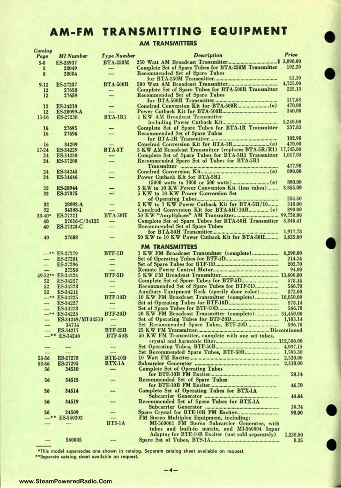
AM-FM TRANSMITTING EQUIPMENT AM TRANSMITTERS
Catalo1 Page MI Number Type Number De,cripiion Price
5-8 ES-28937 BTA-250M 250 Watt AM Broadcast Transmitter ...................................... $ 3,090.00 8 28049 Complete Set of Spare Tubes for BTA-250M Traneminer 102.20 8 28084 Recommended Set of Spare Tubes
for BTA-250M Transmitter ............................................... . 9.12 ES-27237 BTA-500R 500 Watt AM Broadcast Transmitter .............. ... .................... .
51.10 4,725.00
225.13 12 27658 12 27659
12 ES-34210 12 ES-28099-A
13-16 ES-27238 BTA-lRl
16 27695 16 27696
16 34209 17-24 ES•34229 BTA-5T
24 ES-34230 24 ES-37208
24 ES-34245 24 ES-34646
32 ES-28944 32 ES-27075
32 28092-A 32 34308-1
33-40* ES.27221 BTA•50H 40 27616-C/34125 40 ES-27223-C
40 27688
-•• ES-27279 BTF-lD ES-27281 ES.27296
27558 49-52** ES•34224 BTF-5D
52 ES-34227 52 ES-34228 52 ES-34211 -•• ES-34225 BTF-10D
ES-34227 ES-34228
-•• ES.34226 BTF-20D ES-34249 /MI-34510
34714 ES-34217 BTF-25B
- • • ES-34246 BTF-50B
53-56 53-56
56
56
56
56
56
ES-27278 ES-27295
34510
34515
34514
34519
34509
BTF.-10B BTX-lA
-•• ES-560202 BTS-lA
560005
Complete Set of Spare Tubes for BTA•500R Transmitter Recommended Set of Spare Tubes
for BTA-500R Transmitter ......... ...................... .. ............. .. Conelrad Conversion Kit for BTA-S00R. ....... ................ (e) Power Cutback Kit for BTA-500R ......................................... . 1 KW AM Broaden t Transmitter
117.63 470.00 340.00
including Power Cutback Kit. ..... .... ........... ..................... 5,240.00 Complete Set of Spare Tubes for BTA-lR Transmitter 237.83 Recommended Set of Spare Tubes
for BTA-lR Transmitter.......................... .......................... 102.98 Conelrad Conversion Kit for BTA•lR. ........................... (e) 470.00 5 KW AM Broadcast Transmitter (replaces BTA-5R/Rl) 17,745.00 Complete Set of Spare Tubes for BTA-SRl Transmitter 1,017.83 Recommended Spare Set of Tubes for BTA.5Rl
Transmitter .......................................................................... 477.98 Conelrad Conversion Kit .................................................... (e) 890.00 Power Cutback Kit for BTA.5Rl
(5000 watts to 1000 or 500 watts) ............................ (e) 890.00 5 KW to 10 KW Power Conversion Kit (leas tubes)........ 3.855.00 5 KW to 10 KW Power Conversion Set
of Operating Tubes.............................................................. 254.30 5 KW to 1 KW Power Cutback Kit for BTA-5H/10........ 310.00 Conelrad Conversion Kit for BTA-5H/10H ................ (e) 890.00 50 KW "Ampliphase" AM Transmitter .................................. 99,750.00 Complete Set of Spare Tubes for BTA-S0H Transmitter 3,840.41 Recommended Set of Spare Tubes
for BTA-50H Transmitter...................................... ............ 1,917.78 50 KW to 10 KW Power Cutback Kit for BTA-50H.......... 3,625.00
FM TRANSMITTERS 1 KW FM Broadcast Transmitter (complete)........ ............ 6,290.00 Set of Operating Tubes for BTF-1D.......................... ... .. .. ....... 214.14 Set of Spare Tubes for BTF-1D.................... ............................ 202.70 Remote Power Control Motor.................................. ............ .... 94.00 5 KW FM Broadcast Transmitter ............................................ 13,600.00 Complete Set of Spare Tubes for BTF•5D............................ 578.14 Recommended Set of Spare Tubes for BTF-5D.... ............ .. 566.70 Auxiliary Equipment Rack (specify door color).... .......... 372.00 10 KW FM Broadcast Transmitter (complete) .................. 18,850.00 Set of Operating Tubes for BTF-10D................ .. ...... .............. 578.14 Set of Spare Tubes for BTF-10D.... .......................................... 566.70 20 KW FM Broadcast Transmitter (complete) .................. 31,450.00 Set of Operating Tubes for BTF-20D.................................... 1,103.14 Set Recommended Spare Tubes, BTF-20D........................ 596.70 25 KW FM Transmitter .......................... .. ............ ... ............ Discontinued 50 KW FM Transmitter, complete with one set tubes,
crystal and harmonic filter .................. .... .......................... 112,500.00 Set Operating Tubes, BTF-50B........................................ ........ 4,097.15 Set Recommended Spare Tubes, BTF•50B.......................... 1,593.30 10 Watt FM Exciter... .. ............................................................... 2,520.00 Subcarrier Generator ................................................................ 2,310.00 Complete Set of Operating Tubes
for BTE-10B FM Exciter.... ................................................ 58.14 Recommended Set of Spare Tubes
for BTE-10B FM Exciter....................................... ........... 46.70 Complete Set of Operating Tubea for BTX-lA
Subcarrier Generator ........................................................ 44.64 Recommended Set of Spare Tubes for BTX-lA
Subcarrier Generator ........................................................ 39.74 Spare Crystal for BTF.-l0B FM Exciter................................ 90.00 FM Stereo Multiplex Equipment, including:
MI.560001 FM Stereo Subcarrier Generator, with tubes and built-in matrix, and Ml•560004 Input Adaptor for BTE-10B Exciter (not sold separately) 1,250.00
Spare Set of Tubes, BTS-lA.................................................... 8.35
*This model supersedes one shown in catalog. Separate catalog sheet available on request. **Separate catalog sheet available on request.
-4-
www.SteamPoweredRadio.Com

Catalo1 Pa1• MI Numb• 57-58
59-62 59-62
61-62 61-62 61-62 61-62 61-62
62 62 62 62 62 62 62
62 62 62 62
62 62 62 62
27537 / 27538-A 27539 / 27526 27556 27220 27516 27519 27509-A 28027-A 27544 27543-3 27524-1 27755-4 27545-1 27524-3 27966
27542 27687 27522 27523
27517 27518 27520 27540
INPUT AND MONITORING
Type Number De1cription Price
BTR-llB BTR-20A BTRX-40A
Essential Input and Monitoring for AM Station ...... On Application
REMOTE CONTROL Studio and Transmitter Control Unit ...................................... $ 1,025.00 Studio and Transmitter Control Unit.................................... 1,180.00 20-Position Extension for BTR-20A.............. ... ....................... 625.00 Two-Meter AM Monitoring Panel... ................................... .. A-C Voltage Pickup ...................... ............................................. . Tower Lighting Unit .............. ......... .............................. .. .......... . Latching Relay Panel.. ...................................... ....................... . Remote R-F Pickup ........ .................................. .. .. ..................... . Tower Light Monitoring Unit ................................................. . Weatherproof Enclosure for Ml-27544 ................................. . Combining Latching Relay ....................................................... . DPDT High Power R-F Contactor .............. .. ......................... . DPDT Lower Power R-F Contactor .... ................................. . 4PDT Lower Power Latching Relay ............. .. ...................... . Remote R-F Pickup Unit
(Base Currents up to 10 KW) ....................................... . Motor Operated J Frame Breakers ....................................... . Remote Control Accessory Kit for BTA-S0G ..................... . Remote Control Accessory Kit for BTA-250M ... .. .... .. ........ . Remote Control Accessory Kit
for BTA-S00MX/ IMX ....................................................... . Remote Output Control for BTA-SH/ IOH ......................... . Remote Filament Control for BTA-SH-IOH ...................... ..
130.00 80.00
170.00 80.00 75.00 70.90 50.00 25.00
140.00 20.00 30.00
50.00 970.00
1,025.00 550.00
550.00 265.00 265.00
Remote Power Cutback Kit for BTA-SH/ I0H...... .. .............. 170.00 Miacellaneoua Resistors and Part,
for BTA-SH/ I0H ........... ................. .. .... ............................. . 21.00 63-64 31874-A CR-17B Conelrad Receiver ................... ............................. .. ............. Discontinued 65-66 CSU-ISCH 450-470 me, 15 Watt. 115-volt AC Operated Dual
Frequency Transmitter-Receiver Station Unit ..... Discontinued 65-66 CMU-15BIH/B2H 450-470 me, 15 Watt. 6/12 Volta
Mobile Station Transmitter-Receiver Unit ............. Discontinued 65-66 CMU-15C4H 450-470 me, 15 Watt, 115/12 Volta
Remote Pickup Station Unit ..................................... Discontinued 66 CX.SAl Frequency and Modulation Monitor
for Dual Frequency ..................................................... Discontinued 66 31751-B CX-7B Portable Test Meter ........................ .. ................................... Discontinued
66 66 66
67-74 68
69
70 70
71 75-76 75.75 75-76 75-76
75-76
31880-100 31880-125 31880-150
27767-A 27767-B 27767-C 27767-D
27725
BPA-21A BPA-21B BPA-21C BPA-21D
Tranamiaaion Lin&-¼" Coaxial 100 feet ............................................................................... Discontinued 125 feet ............................................................................... Discontinued 150 feet ........ ............................................. .......................... Discontinued
TUNING AND PHASING Antenna Phasing Equipment.......................................... Discontinued I-KW, 5-KW and 10-KW Phasing
and Branching Equipment.................................... Discontinued Alternate I-KW, 5-KW and 10-KW Antenna Phasing
and Branching Equipment.. .................... ............... Discontinued I-KW, 5-KW and 10-KW Line Terminating Units... Discontinued I-KW, 5-KW and 10-KW Open-Type
Wall-Mounted Line Terminating Unit Panela... Di continued SO-KW Phasing and Branching Equipment............. ... Discontinued I-KW Antenna Tuning Unit.................... ............... ................... 500.00
with Remote Metering............... ............................................. 600.00 with Remote Metering and Two-wire Lighting Choke 645.00 with Remote Metering and Three-wire Tower Lighting
Choke ......... ........ ................................................................... 655.00 250/1000 Watt Antenna Tuning Unit
less Remote Meter Kit and Remote Meter.................. 340.00
-5-
www.SteamPoweredRadio.Com
wigfi
Stolen 2 Line Transparent
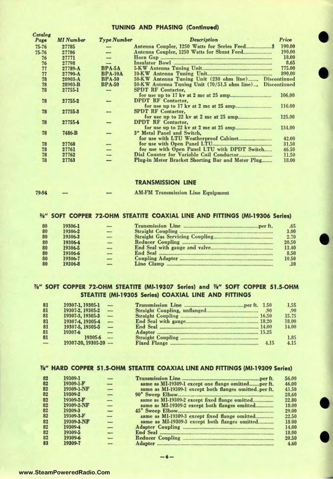
Catalog Page MlNumber 75-76 27785 75-76 27786
76 27771 76 27798 77 27789-A 77 27790-A 78 28903-A 78 28903-B 78 27755-1
78 27755-2
78 27755-3
78 27755-4
78 7486-B
78 27760 78 27761 78 27762 78 27763
79.94
TUNING AND PHASING (Continued)
Type Number Description Price
BPA-SA BPA-IOA BPA-50 BPA-50
Antenna Coupler, 1250 Watts for Series Feed.................... 190.00 Antenna Coupler, 1250 Watts for Shunt Feed...................... 190.00 Horn Gap .......... ................ ... .............. ............... ..................... ... .... 18.00 Insulator Bowl ............................. ... ............ ....... ..... .................... 8.65 5-KW Antenna Tuning Unit....... ..... .......... .... .. .......................... 775.00 10-KW Antenna Tuning Unit.......................... ........ .. .............. 890.00 SO-KW Antenna Tuning Unit (230 ohm line).. ...... Discontinued 50-KW Antenna Tuning Unit (70 / 51.5 ohm line)... Discontinued SPOT RF Contactor,
for use up to 17 kv at 2 me at 25 amp................................ 106.00 DPDT RF Contactor,
for use up to 17 kv at 2 me at 25 amp.................. .. ........ 116.00 SPOT RF Contactor,
for use up to 22 kv at 2 me at 25 amp....... .. ................. 125.00 DPDT RF Contactor,
for use up to 22 kv at 2 me at 25 amp............................ 134.00 3" Metal Panel and Switch,
for use with LTU Weatherproof Cabinet ........................ .. for use with Open Panel LTU ............. .. .......... ......... ........... . for use with Open Panel LTU with DPDT Switch ..... .
Dial Counter for Variable Coil Conductor ...................... ... . Plug-in Meter Bracket Shorting Bar and Meter Plug ....... .
TRANSMISSION LINE
AM-FM Transmission Line Equipment
42.00 31.50 46.50 11.50 18.00
¾" SOFT COPPER 72-OHM STEATITE COAXIAL LINE AND FITTINGS (Ml-19306 Series)
80 80 80 80 80 80 80 80
19306-1 19306-2 19306-3 19306-4 19306-5 19306-6 19306-7 19306-8
Transmission Line ..... ... .. ...... .. .................... .... .. .............. per ft. Straight Coupling .............. ............ .. ... ........................ ............... .. Straight Gas Servicing Coupling ............................ .... ............. . Reducer Coupling ............ .. ................ .. ................... .. ............. ... . End Seal with gauge and valve .................................. ............. . End Seal ................ ...... .. .... .. .......... ............................................... . Coupling Adapter .......... .............. .. ............................................ .. Line Clamp .................................... ......................................... .. .. .
.65 3.00 2.70
20.50 13.40 8.50
10.50 .10
W' SOFT COPPER 72-OHM STEATITE (Ml-19307 Series) and ¾" SOFT COPPER 51.5-OHM STEATITE (Ml-19305 Series) COAXIAL LINE AND FITTINGS
81 81 81 81 81 81 81
19307-1, 19305-1 19307-2, 19305-2 19307-3, 19305-3 19307-4, 19305-4 19307-5, 19305-5 19307-6
19305-6 19307-20, 19305-20 -
Transmission Line .................... .. ........................ per ft . 1.50 Straight Coupling, unflanged........................ ................ .90 Straight Coupling ............................................................ 16.50 End Seal with gauge ........................................................ 18.20 End Seal .............................................. ....... .. ..... .. .............. 14.00 Adapter .......................................... .................................... 15.25 Straight Coupling .... .... .................... ............................... . Fixed Flange ..... ................ ........... .. ... .. ............... .. ... ... ... ... 4.15
1.55 .90
15.75 18.00 14.00
1.85 4.15
'fa" HARD COPPER 51.5-OHM STEATITE COAXIAL LINE AND FITTINGS (Ml-19309 Series)
82 82 82 82 82 82 82 82 82 82 82 82 83
19309-1 19309-1-F 19309-1-NF 19309-2 19309-2-F 19309-2-NF 19309-3 19309-3-F 19309-3-NF 19309-4 19309-5 19309-6 19309-7
Transmission Line .......... ......... ... .................................... .. per ft. same as Ml-19309-1 except one flange omitted ........ per ft. same as Ml-19309-1 except both flanges omitted .. per ft.
90° Sweep Elbow .......... ................... .......... ... .............................. .. same as Ml-19309-2 except fixed flan ge omitted .............. .. same as Ml-19309-2 except both flanges omitted .......... ... .
45° Sweep Elbow ..... ..... .................. .. ........................................... . same as Ml-19309-3 except fixed flange omitted ............. . same as Ml-19309-3 except both flanges omitted ..... .. .... .
Adapter Coupling ................................ .............................. ....... . End Seal ......... .............. ..... ..................................... .. ..... .. ............. . Reducer Coupling .... .... .......... .. ... ...................... ........................ . Adapter ........ .. ........ ....................... ... ..... .... ............ .............. ..... ..... .
-6-
56.00 46.00 43.50 28.60 22.80 18.00 29.00 22.50 18.00 14.00 18.00 20.50 4.60
www.SteamPoweredRadio.Com

' Catalog Page
83 83 83 83 83 83
3/a" HARD COPPER 51 .5-OHM STEA TITE COAXIAL LINE AND FITTINGS (Ml-19309 Series) (Continued)
MINumber 19309·8 19309-9 19309-10 19309-11 19309-12 19309-13
Type Number Description Price 90° Mitre Elbow......................................................... .. ....... Discontinued Adapter ...................................................................... .. ........ Discontinued Fixed Flange, Silver Solder.. .. ...... .................................. Discontinued Inner Conductor Connector ..................................................... :S 3.60 Adapter Connector ..................... ............... .. .................... Discontinued Inner Conductor Connector ........................................... , Discontinued
1¾" HARD COPPER 72-OHM STEATITE COAXIAL LINE AND FITTINGS (Ml-19310 Series) 84 84 84 84 84 84 84 84 84 84 84 84
19310-1 19310-1-F 19310-1-NF 19310-2 19310-2-F 19310-2-NF 19310-3 19310-3-F 19310-3-NF 19310-4 19310•5 19310-11
Transmission Line, 20-ft. Lengths .......................................... .. same as MI-19310-1 except one flange omitted ................ .. same as MI-19310-1 except both flanges omitted ............ ..
90° Sweep Elbow ........................................................ ................. . same as MI-19310-2 except solid flange omitted ............. . same as Ml-19310-2 except both flanges omitted ............ ..
45° Sweep Elbow .................... .. ........................ ........................... . same as Ml-19310-3 except solid flange omitted ........ .. same as Ml-19310·3 except both flanges omitted .. .. .... ..
Adapter Coupling .................. ... ..... .. .................... ....................... . End Seal ...................................................................................... . . Inner Conductor Connector .... .. ............................................. .. .
74.00 69.00 65.00 38.00 34.00 29.00 38.00 34.00 29.00 14.00 25 .00 3.40
1 ¾" HARD COPPER 51.5-OHM VHF STEATITE COAXIAL LINE AND FITTINGS (Ml-19112 Series) 86 86 86 86 86 86 86 86 86 86 86 86 87 87 87 87 87 87 87 87 87 87 87 87 87 87 87 87 87 87 87 87
19112-1 19112·1-F 19112-1-NF 19112-2 19112·2-F 19112-2-NF 19112-3 19l12-3-F 19112-3-NF 19112-4 19112-5 19112-6 19112-7 19112-8 19112-9 19112.10 19112-11 19112-12 19112-13 19112-16 19112·18 19112-18-F 19112-18-NF 19112-19 19112-20 19112-21 19112-22 19112-22-F 19112-22-NF 19112-58 19112-59 19112-60
Transmission Line, 20-ft. Lengths ..................... ...................... . same as Ml-19112-1 except one flange omitted ................ .. same as Ml-19112-1 except both flanges omitted .. .. ........ ..
90° Sweep Elbow ...... ........................................... .. ... ................... . same as MI-19112-2 except fixed flange omitted ............ .. same as MI-19112-2 except both flanges omitted ............ ..
45° Sweep Elbow ................................... ... ........... .. ....... ......... ...... . same ns Ml-19112-3 except fixed flange omitted ............ .. same as Ml-19112-3 except both flanges omitted ............. .
Flange Adapter ........................................................ .... ... ............ . Gas Stop .......................... ...... .......... ..... ........................................ . Reducer Coupling 3¼" to 1%·" (Gassed ) .. ........................ .. Reducer Coupling 3¼" to 1%" (Ungassed) ...................... .. Straight Coupling ...................... ... ................ ............ ....... ........... . Special Inner Conductor ....................... ... ............................. ... .. 0-Ring Gasket ........................ ................................................... . Inner Connector ............................................................ ............. . Line Gassing Accessories .................... .. ...... .................. .. ........... . Emflrgency Cover Plate ............................................................. . Flange Adapter (Ungassed) ..................................................... . 90° Mitre Elbow .... ................................................................... .... .
same as Ml-19112-18 except flange omitted on long leg same as Ml-19112-18 except both flanges omitted .. ........ ..
Hardware Kit ......... ....... .......... ................................................ ... . Flange, Fixed ........................................ .. ... ................................. .. Flange, Swivel ............................................................................ .. 45° Mitre Elbow ............................. .............. ... ............................ . .
same as Ml-19112-22 except flange omitted on long leg same as Ml-19112-22 except both flanges omitted .......... ..
Reducer, 1%" (Ungassed) ....... .. .. ................................... .... .... .. Reducer, 1%" (Gassed) ............................................................ .. Adapter for Ungassed Line ...................................................... ..
67.00 70.00 55.00 38.00 33.00 29.00 38.00 33.00 29.00 15.00 20.00 41.00 21.00 6.30 7.00 .38
1.90 23 .00 5.00 9.30
47.00 41.00 29.00 1.30 4.60 9.45
47.00 41.00 29.00 44.00 46.00 11.40
31/a" HARD COPPER 51.5-OHM VHF STEATITE COAXIAL LINE AND FITTINGS (Ml-19113 Series) 88 19113-B-1 88 19113-8 -1-F 88 19113-B•l-NF 88 19113-B-l-SF
90 19113-C-4 90 19113-C-5 90 19113-C-6 90 19113-C-7 90 19113-~
Transmission Line, 20-fr. Lengths .......................... ................ .. same as MI-19113•8-1 except one flange omitted ............ .. same as MI-19113-8-1 except both flanges omitted ..... .. .. . same as Ml-19113-B-l except one of the two flanges is
a swivel flange ........................................................ .. ........... . Flange Adapter for Gassed Line ............................................. . Gas Stop ........................................................... .. .......................... . Reducer Coupling 3¼" to 1%" ............... ............................... .. Reducer Coupling 3¼" to 1%" for Ungassed Line ........... . Straight 'Coupling ................ ..... ....... .... ........................ .... ........... .
-7-
133.00 121.00 109.00
134.00 35.00 57.00 41.00 21.00 8.70
www.SteamPoweredRadio.Com
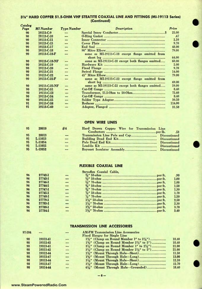
3¼" HARD COPPER 51.5-OHM VHF STEATITE COAXIAL LINE AND FITTINGS (Ml-19113 Series) (Continued)
Catalo1 Page
90 90 90 90 90 90 90
90 90 90 90 90 90
90 90 90 90 90 91 91
95
95 95 95 95 95
96 96 96 96 96 96 96 96 96 96 96
97-104
98 98 98 98 98 98 98 98 98
MINumber 19113-C-9 19113-C-10 19113-C-11 19113-C-13 19113-C-17 19113-C-18 19113-C-18-F
19113-C-18-NF 19113-C-19 19113-C-20 19113-C-21 19113-C-22 19113-C-22-F
19113-C-22-NF 19113-C-Sl 19113-C-53 19113-C-54 19113-C.SS 19113-C-58 19113-C-60
28010
28013 L-13853 L-13854 L-13855 L-13852
27742-1 27743-1 27746-1 27744-1 27747-1 27745-1 27748-1 27779-1 27783-1 27780-1 27784-1
19312-41 19312-42 19313-41 1931342 19312-44 19312-47 19313-44 19313-47 19314-44
Type Number De,cription Prire 25.00
.47 2.10 9.70
48.00 79.00
#6
Special Inner Conductor .. .. ......... .. ................................ ............ . 0-Ring Gasket ..... ................. .. ..... ..... ..................................... .. .... . Inner Connector ............................ ...... ....................................... . Cover Plate ............ ............ .. ....................... ................................ . End Seal .......................................... .. ................................. ........ .. . 90° Mitre Elbow ................................................... .. ...................... .
same as Ml-19113-C-18 except flange omitted from short leg .......... ................. ................... ................................. .
same as Ml-19113-C-18 except both flanges omitted .... .. Hardware Kit .................................................. ........ ... ............. ... . Fixed Flange ................................... ....................... .. ................... . Swivel Flange .......................................... ......................... .. ........ . 45° Mitre Elbow ............ .. ............................................................. .
same as Ml-19113-C-22 except flange omitted from short leg .............................................. ... .............................. .
same as Ml-19113·C-22 except both flanges omitted ..... . Cut-Off Gauge .......... ................................................................... . Transformer, 51.5-0hm to SO-Ohm ......................................... . Cut-Off Gange ............................ ............ ...... .. ............................. . Solder Type Adapter ............................................ ..................... . Reducer .......................................... .. .. .................. ..... ..... ............... . Adapter, Flanged .......... .. ...................... ..................................... .
OPEN WIRE LINES
Hard Drawn Copper Wire for Transmission Line
64.00 60.00 2.00 9.70
14.00 79.00
69.00 59.00
8.40 75.60 8.40
30.50 114.00
31.50
Conductors ................................................................ per lb. .53 Transmission Line Pole and Cap................................. Discontinued Building Dead End Kit........................ .. .. .. ................... Discontinued Pole Dead End Kit.................................. ............. ............ Discontinued Lead-In Kit .................................................... ............. ...... Discontinued Bayonet Insulator Assembly............................ ............. Discontinued
FLEXIBLE COAXIAL LINE
Stryoflex Coaxial Cable, ¾"' SO-ohm .............................. .. ...... .. .............................. per ft. ½"' SO-ohm ................................................... .. ................. per ft. ½" 70•ohm ............ .......................................................... per ft. ¾" SO-ohm ................. .. ............. ... ................................... per ft. ¾" 70-ohm ...................................................................... per ft. ½" SO•ohm .... ......... ... .. ........................................ ............ per ft. ½" 70•ohm ............................... ....................................... per ft. l¼"' SQ.ohm .................................................................... per ft. 1 ¼" 70•ohm ............................................... .. ................ ... per ft. 1%" SQ.ohm .................................. .. ................................ per ft. 1%"' 70-ohm ............................................................ .. ...... per ft.
TRANSMISSION LINE ACCESSORIES
AM•FM Transmission Line Accessories Fixed Hanger for Single Line
1%" (Clamp on Round Member l " to 2¼") ................... . 1%" (Clamp on Round Member 2½·" to 5") ................. . 3¼" (Clamp on Round Member l" ro 2¼") ................. . 3¼" (Clamp on Round Member 2½"' to 5") ................ .. 1 %"' (Mount Through Hole-Short) ..................... ........... .. 1 %" (Mount Through Hole-Long) .......................... ... ... .. 3¼ " (Mount Through Hole-Short) ................................. . 3¼" (Mount Through Hole-Long) ........ .................. .. .... .. 6¼" (Mount Through Hole-Grounded) ....................... .
-8-
.90 1.00 1.00 I.SO 1.30 1.70 1.50 2.50 2.30 3.70 3.40
18.40 18.40 21.00 21.00 11.50 13.00 12.10 12.70 18.40
www.SteamPoweredRadio.Com
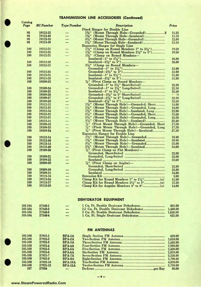
Catalo1 Page
98 98 98 98
100 100 100
100 100
100 100 100 100
100 100 100 100 100 100 100 100 100 100 100 100 100 100
100 100 100 100 100
100 100 100
100 100 100 100 100 100
103-104 103-104 103-104 103-104
105-108 105-108 105-108 105-108 105-108 105-108 105-108 105-108 105-108 105-108
107
Ml Number
19112-15 19112-49 19113-15 )9113-49
19312-23 19312-26 19312-25
19312-28 19313-23
19313-26 19313-25 19313-28 19309-23
19309-24 19309-25 19309-26 19309-27 19309-28 19312-32 19312-33 19312-34 19313-32 19313-33 19313-34 19309-32 19309-33 19309-34
19112-14 19112-48 19113-14 19113-48 19309-20
19309-21 19309-22 19309-29
19309-30 19309-31 19113-16 19113-56 19113-57 19113-59
27348-1 27348-2 27348-3 27348-4
27925-1 27925-2 27925-3 27925-4 27925-5 27925-6 27925-7 27925-8 27925-10 27925-12 27926
TRANSMISSION LINE ACCESSORIES (Continued)
Type Number Description
BFA-IA BFA-2A BFA-3A BFA-4A BFA-5A BFA-6A BFA-7A BFA-SA BFA-lOA BFA-12A
Fixed Hanger for Double Line I%" (Mount Through Hole-Grounded) ...... ... ..... .. .. .. ... ;$ I %'" (Mount Through Hole-Insulated) ......................... . 3¼" (Mount Through Hole-Grounded ) ......................... . 3¼" (Mount Through Hole-Insulated) ................ ........... .
Expansion Hanger for Single Line 1%" (Clamp on Round Members l'" to 2¼" ) ...... ......... . 1%" (Clamp on Round Members 2½"' to 5" ) ............... . 1%'" (Clamp on Round Members-
lnsulated- 1" to 2¼" ) ............. ......................................... . . lnsulated- 2½"' to 5" ) ................... ......... ............ ... .... ........ .
3¼" (Clamp on Round Members-Grounded- 1'" to 2¼"' ) .............. ........ ............................... . Grounded-Z½·" to S") .. ....................... .......................... .. . Insulated- I" to 2¼ ") .. ..................................................... . lnsulated- 2 ½'" to 5" ) ....... ............................................. ... .
½" (Pivot Clamp on Round Members-Grounded- 1" to 2¼" Short.Swivel) .... ......... ................ . Grounded- I " to 2¼" Long-Swivel) ............................. . Insulated- I" to 2¼" ) ........... ............................................ . Grounded- 2¼'" to 5" Short-Swivel ) ........................ ..... . Grounded- 2¼·" to 5" Long-Swivel) ............................. . lnsulated- 2¼'" to 5"" ) ......... .............................................. .
1%" (Mount Through Hole) - Grounded, Short ........... . 1%'" (Mount Through Hole)- Grounded, Lon g ........... . 1%" (Mount Through Hole) - lnsulated, Long ............. . 3¼'" (Mount Through Hole) - Grounded, Short ........... . 3¼·" (Mount Through Hole) - Grounded, Long ....... .. .. . 3¼'" (Mount Through Hole)-lnsulated) ....................... . ½" (Pivot Mount Through Hole)- Grounded, Short ½" (Pivot Mount Through Hole) - Grounded, Long ½" (Pivot Mount Through Hole )- lnsulated ........ .. ..... .
Expansion Hanger for Double Line 1%" (Mount Through Hole) - Grounded ..... .............. .. .. . 1%" (Mount Through Hole) - lnsulated .... .. .. ................. . 3¼" (Mount Through Hole )- Grounded .................... ... . 3¼" (Mount Through Hole) - Insulated ......................... . ½'" (Pivot Clamp on Flat Members) -
Grounded, Short-Swivel .... .............................. ................. . Grounded, Long-Swivel .... ...... ...... .. .................... ............. . Insulated ............................... ................... ... ................. ......... .
½'" (Pivot Clamp on Angles) -Grounded, Short-Swivel .............. ........................... .......... . Grounded, Long-Swivel ... .. ........... ............ ... ....... ............ .. Insulated ............................................ ·-· ······ ··························
Extension Kit ....... .. ....... .......... .. ....................... ........................ .... . Clamp Kit for Round Members l" to 2¼" ............ ........ (e) Clamp Kit for Round Members 2½ " to 5" .................. .. (e) Clamp Kit for Angular Members 4" to 811
•• •• •••••••••••••••••• (e)
DEHYDRATOR EQUIPMENT
l Cu. Ft. Double Desiccant Dehydrator .......................... .... .. 1.5 Cu. Ft. Double Desiccant Dehydrator ........................... . 2 Cu. Ft. Double Desiccant Dehydrator .............................. .. 1 Cu. Ft. Single Desiccant Dehydrator .......... ....................... .
FM ANTENNAS
Single Section FM Antenna ........... ....................... ................ ... . Two-Section FM Antenna ......................................................... . Three-Section FM Antenna .... .................................................. .. Four-Section FM Antenna .... .......... .. .................. .. ..................... . Five-Section FM Antenna ........... ........... ................................... . Six-Section FM Antenna ........ ....... ... .... .. ................................... . Seven-Section FM Antenna .............................. ... ...................... . Eight-Section FM Antenna ...................................................... .. Ten-Section FM Antenna .. ........................................................ .. Twelve-Section FM Antenna .. .. ..... .......... .. .. .............................. . De-icers .... ...................... ...... ... ....................... .................. per Bay
-9-
Price
11.25 13.10 12.00 31.50
19.50 19.50
26.00 26.00
23.00 23 .00 31.00 31.00
22.30 22.30 32.60 ~, ., '(0
22.30 32.60 14.00 14.00 22.00 15.60 16.20 23.40 17.30 17.30 27.30
18.40 38.00 25.00 54.00
22.00 22.00 32.60
22.80 22.80 34.00 3.00
11.60 15.20 14.00
805.00 1,480.00 1,840.00
625.00
620.00 1,010.00 1,450.00 1,930.00 2,420.00 2,810.00 3,320.00 3,700.00 4,830.00 5,750.00
80.00
www.SteamPoweredRadio.Com
wigfi
Stolen 2 Line Transparent
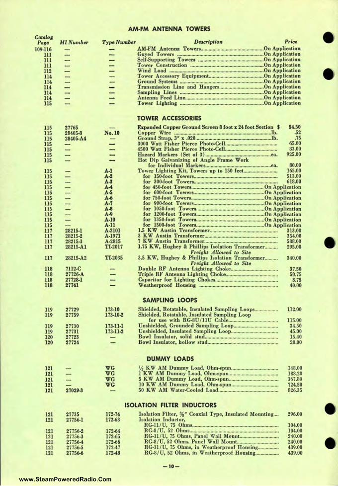
Catalo1 Page Ml Number
109•116 111 Ill 111 112 114 114 114 114 114 115
115 115 115 115 115 115 115
115 115 115 115 115 115 115 115 115 115 115 117 117 117 117
117
118 118 118 118
119 119
119 119 120 120
121 121 121 121 121
121 121
121 121 121 121 121
27765 28405•8 28405•A4
28215•1 28215•2 28215.3 28215•Al
28215•A2
1112.c 27726•A 27728-1 27741
27729 27759
27730 27731 27723 27724
270211-3
27735 27756•1
27756•2 27756•3 27756-4 27756•5 27756-6
AM-FM ANTENNA TOWERS
Type Number Description Price
No.IO
A-1 A-2 A-3 A-4 A-5 A-6 A-7 A-8 A-9 A-10 A-11 A-2101 A•l971 A.2315 Tl-2017
TI.2035
173-10 173-10·2
173•11·1 173·11-2
WG WG WG WG
112.74 172•63
172•64 172•65 172•66 172-47 172-48
AM·FM Antenna Towers ................................................ On Application Guyed Towers .................................................................. On Application Self-Supporting Towers .................................................. On Application Tower Construction .................. .. ...................... .............. On Application Wind Load ........................................................................ On Application Tower Accessory Equipment.. .. .... .. ................................ On Application Ground Systems ................................................................ On Application Transmission Line and Hangers ...... ........ .. .................. On Application Sampling Lines .......................... ...................... ................ On Application Antenna Feed Line .......... ...................................... ........ .... On Application Tower Lighting ......... ....................................... .. ............ .. On Application
TOWER ACCESSORIES
Expanded Copper Ground Screen 8 foot x 24 foot Section $ Copper Wire .............. ............................................................ lb. Ground Strap, 3·11 x .020 ......................................................... .lb. 3000 Watt Fisher Pierce Photo•Cell ....................................... . 4500 Watt Fisher Pierce Photo•Cell ....................................... . Hazard Marken ( Set of 3) .................................................. ea. Hot Dip Galvanizing of Angle Frame Work
54.50 .52 .75
65.00 83.00
925.00
for Individual Markers ...................... ............................ ea. 80.00 Tower Lighting Kit, Towers up to 150 feet...... ................. ... 165.00
for ISO.foot Towers................................................................ 513.00 for 300.foot Towers................................................................ 618.00 for 450•foot Towers ........................................ ............... On Application for 600.foot Towers .... .................................................. On Application for 750.foot Towers ........................................................ On Application for 900.foot Towers ...................................................... On Application for 1050•foot Towera .................................................... On Application for 1200•foot Towers ...................... .......... .................... On Application for 1350.foot Towera ................................ .................... On Application for 1500.foot Towers .................................. .................. On Application
1.5 KW Austin Transformer.................................................... 313.00 3 KW Austin Transformer........................................ ................ 354.00 7 KW Austin Transformer.. ......................... .. ................. .......... 588.00 1.75 KW, Hughey & Phillips Isolation Transformer......... . 295.00
Freight Allowed to Site 3.5 KW, Hughey & Phillips Isolation Transformer.......... 340.00
Freight Allowed to Site Double RF Antenna Lighting Choke .................................. .. Triple RF Antenna Lighting Choke ........................... .. ......... .. Capadtor for Lighting Chokes .................... .. ......................... . Weatherproof Housing ........................................................... .
SAMPLING LOOPS
Shielded, Rotatable, Insulated Sampling Loops ................ .. Shielded, Rotatable, Insulated Sampling Loop
for use with RG·8U / 11U Cable .................................... .. Unshielded, Grounded Sampling Loop ................................ .. Unshielded, Insulated Sampling Loop ...... ...................... .. ..... . Bowl Insulator, solid stud .... ... .. .............................................. . Bowl Insulator, hollow stud ...................... .. ............................. .
DUMMY LOADS
½ KW AM Dummy Load, Ohm•spun ................... ... ............ .. 1 KW AM Dummy Load, Ohm.spun .................................... .. 5 KW AM Dummy Load, Ohm•spun ................... .. ................ . 10 KW AM Dummy Load, Ohm.spun .. .. ............... ................ . 50 KW AM Water•Cooled Load ............................................. .
ISOLATION FILTER INDUCTORS
Isolation Filter, ¾" Coaxial Type, Insulated Mounting .... I solation Inductor,
RG•ll /U, 75 Ohms ........................ .. .................................. .. .. . . RG·8 /U, 52 Ohms ...... .......................................... .. .. .. ............. . RG•ll /U, 75 Ohms, Panel Wall Mount.. .. .................. .. .... .. RG·8 /U, 52 Ohms, Panel Wall Mount .... ..... .......... .. _ ........ . RG.11 /U, 75 Ohms, in Weatherproof Housing ............... . RG·8 /U, 52 Ohms, in Weatherproof Housing ....... .......... .
-10-
37.50 50.75
3.75 40.00
112.00
115.00 34.50 45.00 15.40 20.00
148.00 188.20 367.80 724.50 826.35
296.00
104.00 104.00 240.00 240.00 439.00 439.00
www.SteamPoweredRadio.Com
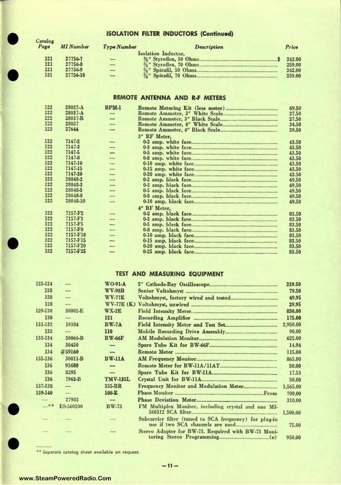
-
--
Catalo1 Pa1e
121 121 121 121
122 122 122 122 122
122 122 122 122 122 122 122 122 122 122 122 122
122 122 122 122 122 122 122 122
123•124 128 128 128
129.130 130
131·132 132
133·134 134 134
135•136 136 136 136
137-138 139.140
••
MINumber
27756-7 27756-8 27756-9 27756-10
28027-A 28037•A 28037-B 28037 27644,
7147-2 7147.3 7147-5 7147-8 7147.10 7147-15 7147-20 28048-2 28048·3 28048-5 28048-8 28048•10
7157•F2 7157.F3 7157.F5 7157•F8 7157-Fl0 7157•Fl5 7157-F20 7157-F25
30002•E
19384
30066-B 30450
#59160 300ll•B 93688 8295 7962·B
27983 ES-560200
ISOLATION FILTER INDUCTORS (Continued)
Type Number Deacription Price Isolation Inductor,
¾" Styroftex, 50 Ohms ..... .................. .. ................... .. .............. $ ¾" Styroftex, 70 Ohms ........................................................... . ¾" Spirafil, 50 Ohms ............................................................. . ¾" Spirafil, 70 Ohms .......................... ..... ... .. .................... .. ... .
242.00 259.00 242.00 259.00
REMOTE ANTENNA AND R-F METERS
BPM-1 Remote Metering Kit (less meter) ................... .................... . Remote Ammeter, 3" White Scale ......................................... . Remote Ammeter, 3·" Black Scale ........................................... . Remote Ammeter, 4" White Scale ................ ..... .................... . Remote Ammeter, 4" Black Scale ......................................... .. . 3" RF Meter,
69.50 27.50 27.50 34.50 39.50
0·2 amp. white face. ........................... .. ........................... ......... 43.50 0.3 amp. white face .................... ·-···"••······························ ·· ···· 43.50 0•5 amp. white face... ..................... .. ........ .. ................. .... .. .. ..... 43.50 0·8 amp. white face. ...................................... ........................... 43.50 0.10 amp. white face............................................ .............. ...... 43.50 0.15 amp. white face. ......... .. ............................... .. ................... 43.50 0·20 amp. white face................... ................... .............. ....... .. ... 43.50 0·2 amp. black face.................................................................. 49.50 0.3 amp. black face... ............................................................... 49.50 0.5 amp. black face... .. ..................... ........................................ 49.50 0•8 amp. black face. .............................. ................................... 49.50 0·10 amp. black face.. ....... .. ... .. .... .. ..... .. ... ................................ 49.50
4" RF Meter, 0·2 amp. black {ace................ .. .... ................ ............................ 83.50 0.3 amp. black face.. ........ ............ ................... ........... .... .......... 83.50 0.5 amp. black face............................ ...................................... 83.50 0·8 amp. black face.................................. .... .. ...... .................. .. 83.50 0·10 amp. black face........ .......... .. ... ............ .............................. 83.50 0.15 amp. black face...... ....... ....... ... .. ....................................... 83.50 0.20 amp. black face...... ........... .......................... ... .................. 83.50 0•25 amp. black face. ..................... .. ...................... .. ........ .... .... 83.50
TEST AND MEASURING EQUIPMENT
WO-9l•A 5" Cathode-Ray O1cillo1cope .................... .. .. ........................... . WV-98B Senior Voltohmyat .......................................................... .. ......... . WV•77E Voltohmyst, factory wired and teated ................. ........... ..... .. . WV-77E (K) Voltohmy•t. unwired ............ .. ..... ...... ................... ..................... . WX-2E Field Intensity Meter ................................................................. . 121 Recording Amplifier ............................................................... . BW-7A Field Intensity Meter and Test Set ...................................... .. 110 Mobile Recording Drive A11embly ................................. .. .... . BW-66F AM Modulation Monitor ........................................................... .
BW-llA
TMV-13SL 335.BR 108-E
Spare Tube Kit for BW-66F ................................................... . Remote Meter ............................... .............................................. . AM Frequency Monitor ....................................... .. .. ..... ............. . Remote Meter for BW-llA/llAT ............ ............................... . Spare Tube Kit for BW-llA ................................................ .. Crystal Unit for BW-llA. ........................................................ . Frequency Monitor and Modulation Meter .......... ............... . Phase Monitor ......... ........................................................... From
239.50 79.50 49.95 29.95
850.00 175.00
2,950.00 90.00
625.00 14.94
115.00 865.00 50.00 17.53 50.00
1,565.00 700.00
Phase Deviation Meter ....................... _..................................... 310.00 BW•73 FM Multiplex Monitor, including crystal and one MI.
560312 SCA filter. ........................... .............................. .. ...... 1,500.00 Suhcarrier filter (tuned to SCA frequency) for plug•in
use if two SCA channels are used................................ 75.00 Stereo Adapter for BW.73. Required with BW•73 Moni•
toring Stereo Programming .... .............. .................... ( e) 950.00
•• Separate catalog sheet available on request.
-11-
www.SteamPoweredRadio.Com
wigfi
Stolen 2 Line Transparent
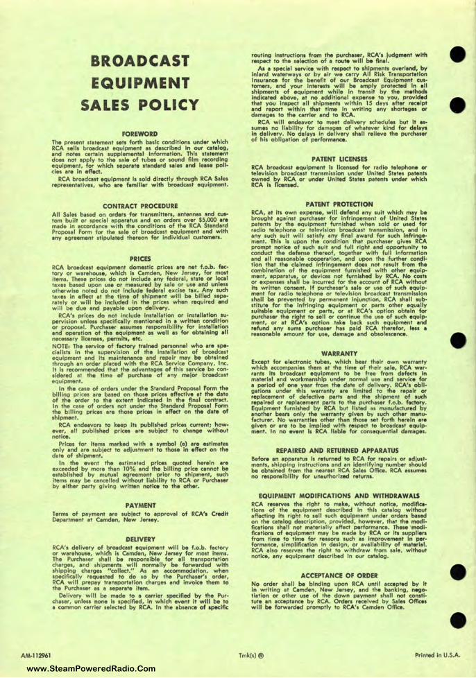
AM-112961
BROADCAST EQUIPMENT
SALES POLICY
FOREWORD The present statement sets forth basic conditions under which RCA sells broadcast equipment es described In our catalog, and notes certain supplemental Information. This statement does not apply to the sale of tubes or sound fllm recording equipment, for which separate atand• rd aales and lease policies are In effect.
RCA broadcast equipment Is sold directly through RCA Sales representatives, who are familiar with broadcast equipment.
CONTRACT PROCEDURE All Sales based on orders for transmitters, antennas and cu•• tom built or special apparatus and on orders over $5,000 are made In accordance with the conditions of the RCA Standard Proposal Form for the sa le of broadcast equipment and with any agreement stipulated thereon for individual customers.
PRICES RCA broadcast equipment domestic prices are net f.o.b. fac• tory or warehouse, which Is Camden, New Jersey, for most Items. These prices do not Include any federal, state or local taxes based upon use or measured by sale or use and unless otherwise noted do not Include federal excise tax. Any such taxes In effect at the time of shipment will be billed aepa• rately or will be Included In the prices when requ ired and will be due and payable upon delivery.
RCA's prices do not Include Installation or Installation su• pervlsion unless specifically mentioned In a written condition or proposal. Purchaser assumes responsibility for Installation and operation of the equipment II well as for obtaining all necessary licenses, permits, etc. NOTE: The service of factory trained personnel who are specialists In the supervision of the Installation of broadcast equipment and Its maintenance and repair may be obtained through an order placed with the RCA Service Company, Inc. It Is recommended that the advantages of this service be con• sldered at the time of purchase of any major broadcast equipment.
In the case of orders under the Standard Proposal Form the billing prices are based on those prices effective at the date of the order to the extent Indicated In the final contract. In the case of orders not under the Standard Proposal Form the billing prices are thoae prices In effect on the date of shipment.
RCA endeavors to keep Its published prices current; how• ever, all published prices are subject to change without notice.
Prices for Items marked with a symbol (e) are estimates only and are subject to adjustment to those In effect on the date of shipment.
In the event the estimated prices quoted herein are exceeded by more than 10% and the billing price cannot be established by mutual agreement prior to shipment, such Items may be cancelled without liability to RCA or Purchaser by either party giving written notice to the other.
PAYMENT Terms of payment are subject to approval of RCA'• Credit Department at Camden, New Jersey.
DELIVERY RCA', delivery of broadcast equipment will be f.o.b. factory or warehouse, whldi Is Camden, New Jersey for most Items. The Purchaser shall be responsible for all transportation charges, and shipments will normally be forwarded with shipping charges "collect." As an accommodation, when specifically requested to do so by the Purchaser's order, RCA will prepay transportation charges and Invoice them to the Purchaser as a aeparate Item.
Delivery will be made to a carrier specified by the Purchaser, unless none Is specified, In which event It will be to a common carrier selected by RCA. In the absence of 1peclflc
routing Instruction, from the purchuer, RCA', judgment with respect to the selection of a route will be final.
As a special service with respect to shipments overland, by Inland waterways or by air we carry All Risk Transportation Insurance for the benefit of our Broadcast Equipment cus• tomers, and your Interests will be amply protected In all shipments of equipment while In transit by the methods Indicated above, at no additional expense to you, provided that you Inspect all shipments within 15 days after receipt and report within that time In writing any shortages or damages to the carrier and to RCA.
RCA will endeavor to meet delivery schedules but It as• sumes no liability for damages of whatever kind for delay, in delivery. No delays In delivery shall relieve the purchaser of his obligation of performance.
PATENT LICENSES RCA broadcast equipment Is licensed for radio telephone or television broadcast transmission under United States patents owned by RCA or under United States patents under which RCA Is licensed.
PATENT PROTECTION RCA, at Its own expense, will defend any suit which may be brought against purchaser for infringement of United States patents by the equipment furnished when sold or used for radio telephone or television broadcast transmission, and In any such suit will satisfy any flnal award for such Infringement. This is upon the cond ition that purchaser gives RCA prompt notice of such suit and full right and opportunity to conduct the defense thereof, together with full Information and all reasonable cooperation, and upon the further condition that the claimed infringement does not result from the combination of the equipment furnished with other equip• ment, apparatus, or devices not furnished by RCA. No costs or expenses shall be Incurred for the account of RCA without its written consent. If purchaser's sale or use of such equipment for radio telephone or television broadcast transmlnlon shall be prevented by permanent Injunction, RCA shall sub• stitute for the Infringing equipment or parts other equally suitable equipment or parts, or at RCA', option obtain for purchaser the right to sell or continue the use of such equipment, or at RCA'• option take back such equipment and refund any sums purchaser has paid RCA therefor, less • reasonable amount for use, damage and obsolescence.
WARRANTY Except for electronic tubes, which bear their own warranty which accompanies them at the time of their sale, RCA war• rants Its broadcast equipment to be free from defects In material and workmanship under normal use and service for a period of one year from the date of delivery. RCA'• obligations under this warranty are limited to the repair or replacement of defective parts and the shipment of auch repaired or replacement parts to the purchaser f.o.b. factory . Equipment furnished by RCA but listed as manufactured by another bears only the werrenty given by such other manufacturer. No warranties other than those set forth herein are given or are to be Implied with respect to broadcast equipment. In no event la RCA liable for consequentia l damages.
REPAIRED AND RETURNED APPARATUS Before an apparatus Is returned to RCA for repairs or adjustments, , hipping instructions end an identifying number should be obtained from the nearest RCA Sales Office. RCA assumes no responsibility for unauthorized return,.
EQUIPMENT MODIFICATIONS AND WITHDRAWALS RCA reserve, the right to make, without notice, modlflc•• !Ions of the equipment described In this catalog without affecting Its right to aell such equipment under orders based on the catalog description, provided, however, that the modi• fications shall not materially affect performance. These modifications of equipment may be made by RCA or lta auppllers from time to time for reasons such as improvement In performance, slmpllflcatlon In design, or availability of materiel. RCA elso reserves the right to withdraw from sale, without notice, any equipment described In our catalog.
ACCEPTANCE OF ORDER No order shall be binding upon RCA until accepted by It in writing at Camden, New Jersey, and the banking, negotiation or other use of the down payment shall not constitute an acceptance by RCA. Orders received by Sales Offices will be forwarded promptly to RCA'• Camden Office.
-
--
Tmk(s)® Printed in U.S.A.
www.SteamPoweredRadio.Com
Related Documents