Strength of Rectangular Section in Bending 4 4 Location of Reinforcement Behavior of Beam under Load Beam Design Requirements Working Stress Design (WSD) Practical Design of RC Beam Reinforced Concrete Design Reinforced Concrete Design Asst.Prof.Dr.Mongkol JIRAVACHARADET S U R A N A R E E UNIVERSITY OF TECHNOLOGY INSTITUTE OF ENGINEERING SCHOOL OF CIVIL ENGINEERING

Rc04 bending2
Aug 07, 2015
Welcome message from author
This document is posted to help you gain knowledge. Please leave a comment to let me know what you think about it! Share it to your friends and learn new things together.
Transcript
Strength of Rectangular Section in Bending
44
� Location of Reinforcement
� Behavior of Beam under Load
� Beam Design Requirements
� Working Stress Design (WSD)
� Practical Design of RC Beam
Reinforced Concrete DesignReinforced Concrete Design
Asst.Prof.Dr.Mongkol JIRAVACHARADET
S U R A N A R E E
UNIVERSITY OF TECHNOLOGY
INSTITUTE OF ENGINEERING
SCHOOL OF CIVIL ENGINEERING

Location of ReinforcementLocation of Reinforcement
•• Simply supported beamSimply supported beam
Concrete cracks due to tension, and as a result, reinforcement iConcrete cracks due to tension, and as a result, reinforcement is requireds required
where flexure, axial loads, or shrinkage effects cause tensile swhere flexure, axial loads, or shrinkage effects cause tensile stresses.tresses.
tensile stresses and cracks are
developed along bottom of the beam
BMD
longitudinal reinforcement is placed
closed to the bottom side of the beam
Positive
Moment

Location of ReinforcementLocation of Reinforcement
• Cantilever beam
- Top bars
- Ties and anchorage
to support

•• Continuous beamContinuous beam
Location of ReinforcementLocation of Reinforcement

Location of ReinforcementLocation of Reinforcement
• Continuous beam with 2 spans
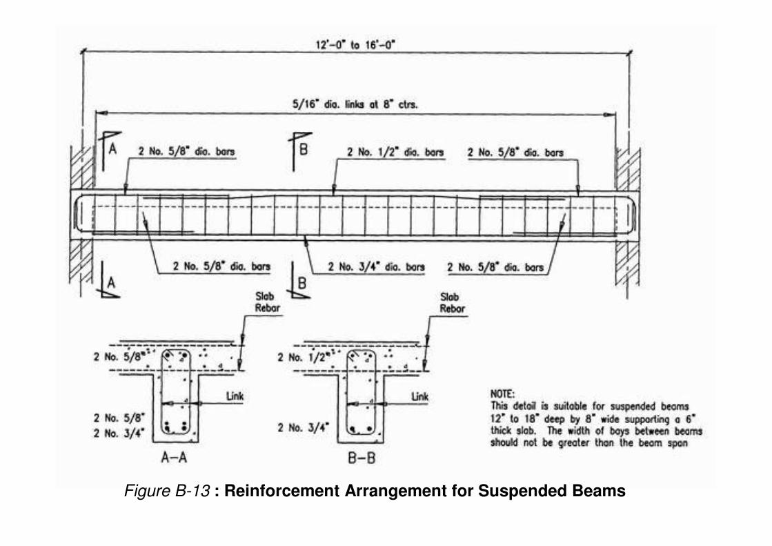
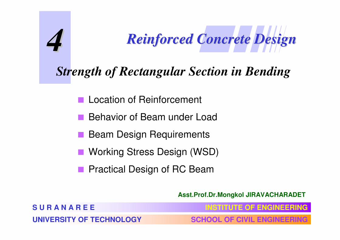
Figure B-13 : Reinforcement Arrangement for Suspended Beams

Figure B-14 : Reinforcement Arrangement for
Suspended Cantilever Beams

Behavior of Beam under Load
Working Stress Condition
sε
cf f ′<cε
T = As fs
C
w
L
cε 2.0r cf f f ′< =
cf f ′<Elastic Bending (Plain Concrete)
cε

s yε ε<T = As fs
C
Brittle failure mode
s yf f<
s yε ε≥T = As fs
C
Ductile failure mode
s yf f=
Crushing
εcu= 0.003
εc < 0.003

Beam Design Requirements
1) Minimum Depth (for deflection control)
oneway
slabL/24 L/28 L/10L/20
BEAM L/18.5 L/21 L/8L/16
2) Temperature Steel (for slab)
As
t
bSR24: As = 0.0025 bt
SD30: As = 0.0020 bt
SD40: As = 0.0018 bt
fy > 4,000 ksc: As = 0.0018� 4,000 bt
fy

3) Minimum Steel (for beam)
AsAs min = 14 / fy
To ensure that steel not fail before first crack
5) Bar Spacing
> 4/3 max. aggregate size
4) Concrete Covering
��������
stirrup
���������
Durability and Fire protection

WSD of Beam for Moment
Assumptions:
1) Section remains plane
2) Stress proportioned to Strain
3) Concrete not take tension
4) No concrete-steel slip
Modular ratio (n):
62.04 10 134
15,100
s
c c c
En
E f f
×= = ≈
′ ′

Effective Depth (d) : Distance from compression face to centroid of steel
d
d
compression face
b
kd
cε
sε s s
s s s
T A f
f E ε
=
=
N.A.
c c cf E ε=C
jd
Cracked transformed section
strain condition force equilibrium

Equilibrium ΣFx= 0 :
Compression = Tension
1
2c s sf b kd A f=
Compression in concrete:1
2cC f b kd=
Tension in steel:s sT A f=
s s
s s s
T A f
f E ε
=
=
N.A.
c c cf E ε=C
jd
kd
Reinforcement ratio: /sA bdρ =
2c
s
f
f k
ρ= 1

Strain compatibility:
1
/
/ 1
1
c
s
c c
s s
c
s
kd k
d kd k
f E k
f E k
f kn
f k
εε= =
− −
=−
=−
2
d
kd
cε
sε
Analysis: know ρ find k 1 2 ( )22k n n nρ ρ ρ= + −
Design: know fc , fs find k 21
1
c
sc s
c
n fk
fn f f
n f
= =+ +

Example 3.1: = 150 ksc , fs = 1,500 ksccf ′
13410.94 10 (nearest integer)
150
0.375(150) 56 ksc
10.2515
1,5001
9(56)
c
n
f
k
= = ⇒
= =
= =+
Allowable Stresses
20.33 60 kg/cmc cf f ′= ≤
Plain concrete:
SR24: fs = 0.5(2,400) = 1,200 ksc
SD30: fs = 0.5(3,000) = 1,500 ksc
SD40, SD50: fs = 1,700 ksc
Steel:
20.375 65 kg/cmc cf f ′= ≤
Reinforced concrete:

Resisting Moment
M
T = As fs
jd
kd/3
1
2cC f k b d=
Moment arm distance : j d
3
kdjd d= −
13
kj = −
Steel:s sM T jd A f jd= × =
Concrete: 2 21
2cM C jd f k j b d R b d= × = =
1
2cR f k j=

Design Step: known M, fc, fs, n
1) Compute parameters
1
1 s c
kf n f
=+
1 / 3j k= −1
2cR f k j=
45
50
55
60
65
fc
(kg/cm2)
R (kg/cm2)
fs=1,200(kg/cm2)
fs=1,500(kg/cm2)
fs=1,700(kg/cm2)
6.260
7.407
8.188
9.386
10.082
n
12
12
11
11
10
5.430
6.463
7.147
8.233
8.835
4.988
5.955
6.587
7.608
8.161

Design Parameter k and j
45
50
55
60
65
fc
(kg/cm2)
fs=1,200(kg/cm2)
fs=1,500(kg/cm2)
fs=1,700(kg/cm2)
0.310
0.333
0.335
0.355
0.351
n
12
12
11
11
10
k j
0.897
0.889
0.888
0.882
0.883
0.241
0.261
0.262
0.280
0.277
k j
0.920
0.913
0.913
0.907
0.908
k j
0.265
0.286
0.287
0.306
0.302
0.912
0.905
0.904
0.898
0.899
1) For greater fs , k becomes smaller → smaller compression area
2) j ≈ 0.9 → moment arm j d ≈ 0.9d can be used in approximation
design.

2) Determine size of section bd2
Such that resisting moment of concrete Mc = R b d 2 ≥ Required M
Usually b ≈ d / 2 : b = 10 cm, 20 cm, 30 cm, 40 cm, . . .
d = 20 cm, 30 cm, 40 cm, 50 cm, . . .
3) Determine steel area
s s s
s
MM A f jd A
f j d= → =From
4) Select steel bars and Detailing

�������� .1 � ������� �������������������� � ��� , ��.2
Bar Dia.Number of Bars
1 2 3 4 5 6
RB6
RB9
DB10
DB12
DB16
DB20
DB25
0.283
0.636
0.785
1.13
2.01
3.14
4.91
0.565
1.27
1.57
2.26
4.02
6.28
9.82
0.848
1.91
2.36
3.53
6.03
9.42
14.73
1.13
2.54
3.14
4.52
8.04
12.57
19.63
1.41
3.18
3.93
5.65
10.05
15.71
24.54
1.70
3.82
4.71
6.79
12.06
18.85
29.45
�������� .3 !����" ��#����$�%��!� �������&� ACI
Member
One-way slab
Beam
Simplesupported
One-endcontinuous
Both-endscontinuous
Cantilever
L/20
L/16
L/24
L/18.5
L/28
L/21
L/10
L/8
L = span length
For steel with fy not equal 4,000 kg/cm2 multiply with 0.4 + fy/7,000

Example 3.2: Working Stress Design of Beam
w = 4 t/m
5.0 m
Concrete: fc = 65 kg/cm2
Steel: fs = 1,700 kg/cm2
From table: n = 10, R = 8.161 kg/cm2
Required moment strength M = (4) (5)2 / 8 = 12.5 t-m
Recommended depth for simple supported beam:
d = L/16 = 500/16 = 31.25 cm
USE section 30 x 50 cm with steel bar DB20
d = 50 - 4(covering) - 2.0/2(bar) = 45 cm

Moment strength of concrete:
Mc = R b d2 = 8.161 (30) (45)2
= 495,781 kg-cm
= 4.96 t-m < 12.5 t-m NG
TRY section 40 x 80 cm d = 75 cm
Mc = R b d2 = 8.161 (40) (75)2
= 1,836,225 kg-cm
= 18.36 t-m > 12.5 t-m OK
Steel area: 25
cm 8.1075908.0700,1
105.12=
×××
==jdf
MA
s
s
Select steel bar 4DB20 (As = 12.57 cm2)

Alternative Solution:
From Mc = R b d2 = required moment M
bR
Md
R
Mdb =⇒=2
For example M = 12.5 t-m, R = 8.161 ksc, b = 40 cm
cm 88.6140161.8
105.12 5
=××
=d
USE section 40 x 80 cm d = 75 cm
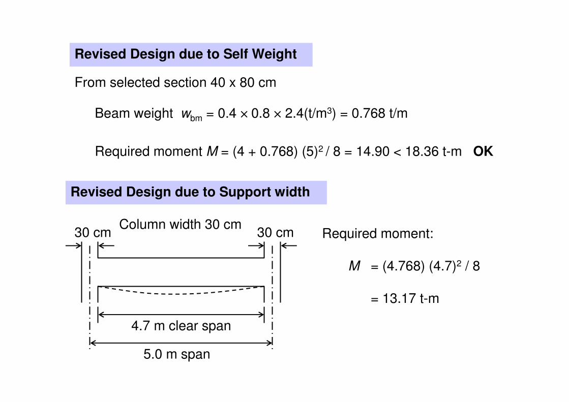
Revised Design due to Self Weight
From selected section 40 x 80 cm
Beam weight wbm = 0.4 × 0.8 × 2.4(t/m3) = 0.768 t/m
Required moment M = (4 + 0.768) (5)2 / 8 = 14.90 < 18.36 t-m OK
Revised Design due to Support width
5.0 m span
30 cm30 cmColumn width 30 cm
4.7 m clear span
Required moment:
M = (4.768) (4.7)2 / 8
= 13.17 t-m

Practical Design of RC Beam
B1 30x60 Mc = 8.02 t-m, Vc = 6.29 t.fc = 65 ksc, fs = 1,500 ksc, n = 10
k = 0.302, j = 0.899, R = 8.835 ksc
b = 30 cm, d = 60 - 5 = 55 cm
Mc = 8.835(30)(55)2/105 = 8.02 t-m
Vc = 0.29(173)1/2(30)(55)/103
= 6.29 t
w = 2.30 t/m
5.00
Load
dl 0.43
wall 0.63
slab 1.24
w 2.30
M± = (1/9)(2.3)(5.0)2 = 6.39 t-m
As± = 6.39×10⁵/(1,500×0.899×55)
= 8.62 cm2
As± = 8.62 cm2 (2DB25)
V = 5.75 t ([email protected] St.)

B2 40x80 Mc = 19.88 t-m, Vc = 11.44 t.
w = 2.64 t/m
8.00 5.00
w = 2.64 t/m
SFD8.54 9.83
12.58 3.37
BMD+13.81
-16.17
+2.15
As13.65
4DB25
2.13
3DB25
15.99
2DB25

GRASP Version 1.02
B11-B12
-47.7369.700.0081.47-92.256
-52.6131.27-92.256.59-28.265
-38.9244.96-28.2625.88-46.354
-43.3440.54-46.3520.75-37.973
-39.3644.52-37.9717.36-53.422
-50.8433.04-53.4239.0301
Fy.j [Ton]Fy.i [Ton]Mz.j [T-m]Mz.pos [T-m]Mz.i [T-m]Membe
r

Analysis of RC Beam
Given: Section As , b, d Materials fc , fs
Find: Mallow = Moment capacity of section
STEP 1 : Locate Neutral Axis (kd)
( ) nnnk ρρρ −+= 22
3/1 kj −=
where ratioent Reinforcem==bd
Asρ
62.04 10 134
15,100
s
c c c
En
E f f
×= = ≈
′ ′

STEP 2 : Resisting Moment
Concrete: 2
2
1dbjkfM cc =
Steel: djfAM sss =
If Mc > Ms , Over reinforcement Mallow = Ms
If Mc < Ms , Under reinforcement Mallow = Mc
Under reinforcement is preferable because steel is weaker
than concrete. The RC beam would fail in ductile mode.

Example 3.3 Determine the moment strength of beam
4 DB 20
As = 12.57 cm2
80 cm
40 cm fc = 65 ksc, fs = 1,700 ksc,
n = 10, d = 75 cm
0419.0,00419.07540
57.12==
×== n
bd
As ρρ
916.03/251.01251.0
0419.0)0419.0(0419.02 2
=−=→=
−+×=
j
k
Mc = 0.5(65)(0.251)(0.916)(40)(75)2/105 = 16.81 t-m
Ms = (12.57)(1,700)(0.916)(75)/105 = 14.68 t-m (control)

Double Reinforcement
When Mreq’d > Mallow
- Increase steel area- Enlarge section
- Double RConly when no choice
εs
εc
M
T = As fs
C = fc k b d1
2
As
A’s
ε’sd’T’ = A’s f’s
As1 fs
As2 fs
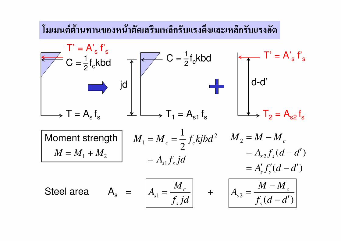
��������������� ������������ ���������������� ������������
T = As fs
C = fckbd1
2
T’ = A’s f’s
T1 = As1 fs
C = fckbd1
2
T2 = As2 fs
T’ = A’s f’s
jd d-d’
2
1
1
1
2c c
s s
M M f kjbd
A f jd
= =
=
2
2 ( )
( )
c
s s
s s
M M M
A f d d
A f d d
= −
′= −
′ ′ ′= −
Steel area As =1
cs
s
MA
f jd= +
2( )
cs
s
M MA
f d d
−=
′−
M = M1 + M2
Moment strength
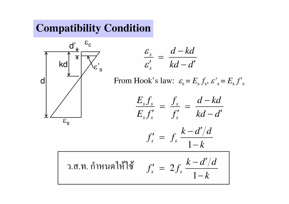
Compatibility Condition
εc
d
d’
kd ε’s
εs
s
s
d kd
kd d
εε
−=
′ ′−
From Hook’s law: εs = Es fs, ε’s = Es f’s
s s s
s s s
E f f d kd
E f f kd d
−= =
′ ′ ′−
1s s
k d df f
k
′−′ =
−
.�.�. ������������ 21
s s
k d df f
k
′−′ =
−
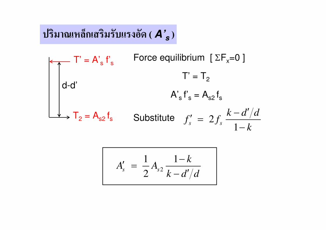
������� ����������������� ( A’s )
T2 = As2 fs
T’ = A’s f’s
d-d’
Force equilibrium [ ΣFx=0 ]
T’ = T2
A’s f’s = As2 fs
Substitute 21
s s
k d df f
k
′−′ =
−
2
1 1
2s s
kA A
k d d
−′ =
′−

���� � ��������� ( k )
εc
d
d’
kd ε’s
εs
Compression = Tension
c sC C T′+ =
1
2c s s s sf bkd A f A f′ ′+ =
Substitute 2 ,1
ss s
Ak d df f
k b dρ
′′−′ ′= =
−
1, s
s c
Akf n f
k b dρ
−= =
( ) ( )222 2 2 2d
k n n nd
ρ ρ ρ ρ ρ ρ′ ′ ′ ′= + + + − +

Example 3.4 Design 40x80 cm beam using double RC
fc = 65 ksc, fs = 1,700 ksc,
n = 10, d = 75 cm
k = 0.277, j = 0.908, R = 8.161 ksc
w = 6 t/m
5.0 m
Required M = (6.768) (5)2 / 8 = 21.15 t-m
Beam weight wbm = 0.4 × 0.8 × 2.4(t/m3) = 0.768 t/m
Mc = Rbd2 = 8.161(40)(75)2/105 = 18.36 t-m < req’d M Double RC
52
1
18.36 1015.86 cm
1,700 0.908 75
cs
s
MA
f jd
×= = =
× ×
52
2
(21.15 18.36) 102.34 cm
( ) 1,700 (75 5)
cs
s
M MA
f d d
− − ×= = =
′− × −

Tension steel As = As1 + As2 = 15.86 + 2.34 = 18.20 cm2
USE 6DB20 (As = 18.85 cm2)
Compression steel
2
2
1 1 1 1 0.2772.34 4.02 cm
2 2 0.277 5 / 75s s
kA A
k d d
− −′ = = × × =
′− −
USE 2DB20 (As = 6.28 cm2)
6DB20
2DB200
.80
m
0.40 m

���������� 175 ���������
3 ������ 3 �������
Related Documents


![com.atlassian.crowd.exception ... · at com.atlassian.crowd.directory.ldap.cache.RemoteDirectoryCacheRefresher.findAllRemoteUsers(R emoteDirectoryCacheRefresher.java:55) ~[crowd-ldap-2.10.2-rc04.jar:na]](https://static.cupdf.com/doc/110x72/5f713879d7129a360b702167/com-at-com-r-emotedirectorycacherefresherjava55-crowd-ldap-2102-rc04jarna.jpg)