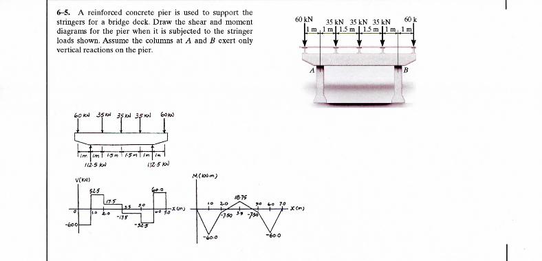
6-5. A rt stringers f< diagrams f loads show vertical ree r Enforced concrete pier is used to support the jr a bridge deck. Draw the shear and moment ™ | 35 kN 35 kN 35 kN *~ . k or the pier when it is subjected to the stringer 1 mr ,l ml 1.5 ml 1.5 mil mr\l m. Assume the columns at A and B exert only 1 T T T T ctions on the pier. ^. - . ^ A™ ^B i 'ml^——_____ —^MMI '' ! trr r L_ J f j t ia s o '/>i f-5 ft i-5#\i i /** Skt) IIZ-SKA !,.« <j<>-° ~\ «™ ^H'-S r xwj r r/T^ T r '/ r-^ 8i '° -'HJ" \JS A / •m \ \ YO y°o

Welcome message from author
This document is posted to help you gain knowledge. Please leave a comment to let me know what you think about it! Share it to your friends and learn new things together.
Transcript
€> 2008 by R.C. Hibbeler. Published by Pearson Prentice Hall, Pearson Education, Inc., Upper Saddle River, NJ. All rights reserved. This material is protected under allcopyright laws as they currently exist. No portion of this material may be reproduced, in any form or by any means, without permission in writing from the publisher.
6-5. A rtstringers f<diagrams floads showvertical ree
r
Enforced concrete pier is used to support the
jr a bridge deck. Draw the shear and moment ™ | 35 kN 35 kN 35 kN *~ .kor the pier when it is subjected to the stringer 1 mr,l ml 1.5 m l 1.5 m i l mr\l
m. Assume the columns at A and B exert only 1 T T T Tctions on the pier.
.̂ - . ̂A™ ^B
i 'ml^—— _____ —^MMI ''!
trr rL_ J
f j tia
s
o
'/>i f-5 ft i-5#\i i /**Skt) IIZ-SKA
!,.« <j<>-°
~\ «™^H'-S r xwj r r/T^ T r '/ r-^8 i ' ° -'HJ" \JS A /
•m \ \YO y°o
6-6. Draw the shear and moment diagrams for the shaft.The bearings at A and B exert only vertical reactions on the ^QQ ̂shaft. Also, express the shear and moment in the shaft as a
X(¥) Nfunction of x within the region 125 mm < x < 725 mm. .
An A i nB
J6
\ll
M(
Jotr— •--^j=F, -ft 815.63 800- K = 0
V=15.6N An *
I*r = 0; «+800U-0.125)- 815.63^.0 125mm 75 mm
M«(lS.6i+100)N m Am
i n *«wj i1*^ \T X • ̂ "^
<)pt
Jj
/, ,\7
© 2008 by R.C. Hibbeler. Published by Pearson Prentice Hall, Pearson Education, Inc., Upper Saddle River, NJ. All rights reserved. This material is protected under allcopyright laws as they currently exist. No portion of this material may be reproduced, in any form or by any means, without permission in writing from the publisher.
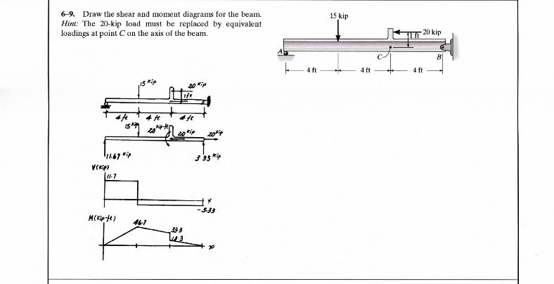
6-9. Draw the shear and moment diagrams for the beam.Hint: The 20-kip load must be replaced by equivalentloadings at point C on the axis of the beam.
15 kip
4f t 4ft 4f t
J 33 *'>
17-7
-3-33
6-10. The engine crane is used to support the engine,which has a weight of 1200 Ib. Draw the shear and momentdiagrams of the boom ABC when it is in the horizontalposition shown.
ft -1(3) - 1200(8) - Or, F, "400016
, =0-, -A, + -(4000) - 1200 - o-. A, = 2000*
+ I F, - 0; ^ - -(4000) =0; A, • 2400 Ib
249
© 2008 by R.C. Hibbeler. Published by Pearson Prentice Hall, Pearson Education, Inc., Upper Saddle River, NJ. All rights reserved. This material is protected under allcopyright laws as they currently exist. No portion of this material may be reproduced, in any form or by any means, without permission in writing from the publisher.
6-21. Draw the shear and moment diagrams for the beamand determine the shear and moment in the beam as 200lb-( tfunctions oix, where 4 f t < x < 10 ft.
1501b/flI I I I
i i i I 1 1 1
200 Ib-lt
150(ji-4)-V+450 = 0
V= 1050-150* Ans - 4 ft 6 f t - 4 ft -
M = -75i2 + 1050* - 3200 Ans
V— n
Mr*' 4 ' 1 u £'
450
47S
'ZOO
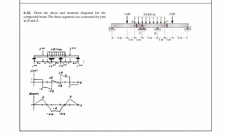
6-22. Draw the shear and moment diagrams for thecompound beam.The three segments are connected by pinsat B and E.
3kN 0.8 kN/m :UN
1m 1m 1m 1 m- 2 m -
ffl
'.S"M/m 3 /
. . l U J J l l 1i ' j •^-" •-—-*• • i
t I T Ti l tr *- hv'n~r *-t'- /- ' *-i
-00-f-x
254
© 2008 by R.C. Hibbeler. Published by Pearson Prentice Hall, Pearson Education, Inc., Upper Saddle River, NJ. All rights reserved. This material is protected under allcopyright laws as they currently exist. No portion of this material may be reproduced, in any form or by any means, without permission in writing from the publisher.
6-38. Draw the shear and moment diagrams for the beam.
18kN/m
sj/m ,
, I 1
| 1
. ̂TTTnrrrrfflin
\)
3m
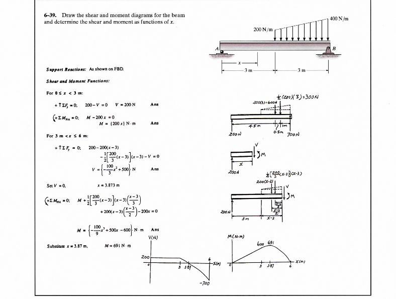
6-39. Draw the shear and moment diagrams for the beamand determine the shear and moment as functions of x.
200N/m rII400 N/m
Support Reactions: As shown on FBD.
SHiar and Momtnt Functions:
For 0 S jr < 3 m:
+ Tl^=»0; 200 -V=0 V = 2 0 0 N
f+£M N A =0; M - 2 0 0 x = 0M = (200*) N m
For 3 m <i S 6 m:
F, = 0; 200-200(j:-3)
Set V = 0,
- 3 m - -3m-
Ans
Ans
700 ft
Ans
3.873 m
X-3
Substitutt x » 3.87 m,
j;' + 500x -60ol N m Ans
vw;M = 6 9 I N - m
Zoo
Jfl/ -«•) 3 J»7 6
262
Related Documents