Welcome message from author
This document is posted to help you gain knowledge. Please leave a comment to let me know what you think about it! Share it to your friends and learn new things together.
Transcript


Evil Genius™ Series
Arduino + Android Projects for the Evil GeniusBike, Scooter, and Chopper Projects for the Evil GeniusBionics for the Evil Genius: 25 Build-It-Yourself ProjectsElectronic Circuits for the Evil Genius, Second Edition: 64 Lessons with ProjectsElectronic Gadgets for the Evil Genius, Second EditionElectronic Gadgets for the Evil Genius: 28 Build-It-Yourself ProjectsElectronic Sensors for the Evil Genius: 54 Electrifying Projects15 Dangerously Mad Projects for the Evil Genius50 Awesome Auto Projects for the Evil Genius50 Green Projects for the Evil Genius50 Model Rocket Projects for the Evil Genius51 High-Tech Practical Jokes for the Evil Genius46 Science Fair Projects for the Evil GeniusFuel Cell Projects for the Evil GeniusHolography Projects for the Evil GeniusMechatronics for the Evil Genius: 25 Build-It-Yourself ProjectsMind Performance Projects for the Evil Genius: 19 Brain-Bending Bio HacksMORE Electronic Gadgets for the Evil Genius: 40 NEW Build-It-Yourself Projects101 Outer Space Projects for the Evil Genius101 Spy Gadgets for the Evil Genius, Second Edition123 PIC® Microcontroller Experiments for the Evil Genius123 Robotics Experiments for the Evil Genius125 Physics Projects for the Evil GeniusPC Mods for the Evil Genius: 25 Custom Builds to Turbocharge Your ComputerPICAXE Microcontroller Projects for the Evil GeniusProgramming Video Games for the Evil GeniusRaspberry Pi Projects for the Evil GeniusRecycling Projects for the Evil GeniusSolar Energy Projects for the Evil GeniusTelephone Projects for the Evil Genius30 Arduino Projects for the Evil Genius, Second EditiontinyAVR Microcontroller Projects for the Evil Genius22 Radio and Receiver Projects for the Evil Genius25 Home Automation Projects for the Evil Genius


Copyright © 2014 by McGraw-Hill Education. All rights reserved. Except as permitted under the United States Copy-right Act of 1976, no part of this publication may be reproduced or distributed in any form or by any means, or storedin a data base or retrieval system, without the prior written permission of the publisher.
ISBN: 978-0-07-181956-5MHID: 0-07-181956-8
The material in this eBook also appears in the print version of this title: ISBN: 978-0-07-182158-2, MHID:0-07-182158-9.
E-book conversion by CodemantraVersion 2.0
All trademarks are trademarks of their respective owners. Rather than put a trademark symbol after every occurrenceof a trademarked name, we use names in an editorial fashion only, and to the benefit of the trademark owner, with nointention of infringement of the trademark. Where such designations appear in this book, they have been printed withinitial caps.
McGraw-Hill Education books are available at special quantity discounts to use as premiums and sales promotionsor for use in corporate training programs. To contact a representative, please visit the Contact Us page atwww.mhprofessional.com.
McGraw-Hill Education, the McGraw-Hill Education logo, TAB, Evil Genius, and related trade dress are trademarksor registered trademarks of McGraw-Hill Education and/or its affiliates in the United States and other countriesand may not be used without written permission. All other trademarks are the property of their respective owners.McGraw-Hill Education is not associated with any product or vendor mentioned in this book.
Raspberry Pi is a trademark of the Raspberry Pi Foundation.
Information contained in this work has been obtained by McGraw-Hill Education from sources believed to be reliable.However, neither McGraw-Hill Education nor its authors guarantee the accuracy or completeness of any informationpublished herein, and neither McGraw-Hill Education nor its authors shall be responsible for any errors, omissions,or damages arising out of use of this information. This work is published with the understanding that McGraw-HillEducation and its authors are supplying information but are not attempting to render engineering or other professionalservices. If such services are required, the assistance of an appropriate professional should be sought.
TERMS OF USE
This is a copyrighted work and McGraw-Hill Education and its licensors reserve all rights in and to the work. Use ofthis work is subject to these terms. Except as permitted under the Copyright Act of 1976 and the right to store andretrieve one copy of the work, you may not decompile, disassemble, reverse engineer, reproduce, modify, create deriv-ative works based upon, transmit, distribute, disseminate, sell, publish or sublicense the work or any part of it withoutMcGraw-Hill Education’s prior consent. You may use the work for your own noncommercial and personal use; anyother use of the work is strictly prohibited. Your right to use the work may be terminated if you fail to comply withthese terms.
THE WORK IS PROVIDED “AS IS.” McGRAW-HILL EDUCATION AND ITS LICENSORS MAKE NOGUARANTEES OR WARRANTIES AS TO THE ACCURACY, ADEQUACY OR COMPLETENESS OF ORRESULTS TO BE OBTAINED FROM USING THE WORK, INCLUDING ANY INFORMATION THAT CANBE ACCESSED THROUGH THE WORK VIA HYPERLINK OR OTHERWISE, AND EXPRESSLY DISCLAIMANY WARRANTY, EXPRESS OR IMPLIED, INCLUDING BUT NOT LIMITED TO IMPLIED WARRANTIESOF MERCHANTABILITY OR FITNESS FOR A PARTICULAR PURPOSE. McGraw-Hill Education and its licen-sors do not warrant or guarantee that the functions contained in the work will meet your requirements or that its opera-tion will be uninterrupted or error free. Neither McGraw-Hill Education nor its licensors shall be liable to you or any-one else for any inaccuracy, error or omission, regardless of cause, in the work or for any damages resulting therefrom.McGraw-Hill Education has no responsibility for the content of any information accessed through the work. Under nocircumstances shall McGraw-Hill Education and/or its licensors be liable for any indirect, incidental, special, punitive,consequential or similar damages that result from the use of or inability to use the work, even if any of them has beenadvised of the possibility of such damages. This limitation of liability shall apply to any claim or cause whatsoeverwhether such claim or cause arises in contract, tort or otherwise.

To Karen, my lovely soul mate and most ardent supporter.Her faith in me never wavers and is my core strength.

About the Author
Donald Norris has a degree in electrical engineering and an MBA specializing in production management. He is cur-rently teaching undergrad and grad courses in the IT subject area at Southern New Hampshire University. He has alsocreated and taught several robotics courses there. He has over 30 years of teaching experience as an adjunct professorat a variety of colleges and universities.
Mr. Norris retired from civilian government service with the U.S. Navy, where he specialized in acoustics relatedto nuclear submarines and associated advanced digital signal processing. Since then, he has spent more than 17 yearsas a professional software developer using C, C#, C++, Python, and Java, as well as 5 years as a certified IT securityconsultant.
Mr. Norris started a consultancy, Norris Embedded Software Solutions (dba NESS LLC), that specializes in de-veloping application solutions using microprocessors and microcontrollers. He likes to think of himself as a perpetualhobbyist and geek and is always trying out new approaches and out-of-the-box experiments. He is a licensed privatepilot, photography buff, amateur radio operator, avid runner, and, last but very important, new grandfather—here’s toyou, Hudson.

Contents
PrefaceAcknowledgments
1 Introduction to the Raspberry PiHardwareSoftwareSummary
2 LED Blinker ProjectPrototype BoardSolderingAccessing the GPIO Pinsapt-get CommandLED ProjectSummary
3 MP3 Player ProjectPrototype ConnectorPortable Stereo SpeakerAudio File FormatsHardware Switch InputsThinking in RasPi TimeMP3 Project RequirementsSummary
4 Camera ControllerProject RequirementsCamera Shutter OperationElectronic FlashOptoisolator InterfacesSound and Laser ModulesInterface ConnectionsTime-Lapse FunctionSummary
5 GPSIntroductionThe Basics of How GPS FunctionsThe Ultimate GPS ReceiverNMEA ProtocolThe gpsd AppsSummary
6 Earthquake DetectorIntroductionSeismology and EarthquakesAnalog-to-Digital ConversionSerial Peripheral Interface

Connecting and Testing the MCP3008 with the RasPiSeismic Data AnalysisOperational SystemSummary
7 Home AutomationIntroductionZ-Wave Mesh NetworkRasPi and Z-Wave InterfaceSSH LoginOpen Z-Wave SoftwareSummary
8 Home Security ControllerIntroductionWebcam SelectionLaser Trip AssemblyMotion Software PackageWebcam ViewingLaser Trip ProgramAdditional SensorsSummary
9 NFC/RFID ReaderIntroductionHow NFC WorksInstalling libnfcHardware InstallationInitial CheckoutProject ProgramFuture ExpansionSummary
10 1-Wire Weather StationIntroductionWeather Station Design1-Wire Protocol1-Wire SnifferSet Up the Weather Station Hardware1-Wire File SystemViewing the Weather DataPacket SniffingFuture ExpansionSummary
11 Local and Remote Logic ControllerIntroduction1-Wire External Control Board1-Wire File System (owfs) Installation and ConfigurationLinux, Hardware, and FUSETest Sequences for the 8 Channel I/O Board

Python Test ProgramSniffer MonitoringAndroid Remote ControlTesting the Web Server with a BrowserSummary
12 Robotic Car: Part 1IntroductionOverviewChassis and Drive MotorsServos
13 Robotic Car: Part 2IntroductionRobotic Car Block DiagramI2C SoftwareBluetooth SoftwareRobot Car ProgramOperating the Robotic CarFuture ExpansionsSummary
14 Radon DetectorIntroductionRadioactivity and RadonK2645 Geiger-Muller CounterInitial Test ConfigurationBuilding a Portable Radiation DetectorOperating the Portable Geiger CounterModifications and ExpansionsSummary
15 Serving Up Time with an RTC and NTPIntroductionReal-Time Clock (RTC)RTC SoftwareIntroduction to the Network Time Protocol (NTP)Building a RasPi NTP ServerSummary
Index

Preface
This Raspberry Pi project book is not only about building a series of interesting projects but also about providing aneducation regarding the underlying project technologies. I am positive that my over-30-years’ experience as a collegeeducator forced me to ensure that readers could not only build the projects but also understand why they function asdesigned.
Building a successful project is rewarding unto itself, but understanding why and how it functions is far more im-portant. The reader should expect a manifold increase in experience with the Raspberry Pi if a commitment is madeto expend the time and energy to complete most, if not all, of the projects. I learned a lot while completing them;sometimes things worked out fine, while other times they were not successful. But that’s the joy of experimenting. AsProfessor Einstein once stated, “Anyone who has never made a mistake has never tried anything new.”
The joy of learning about and building projects is the core concept within this book. I designed and built all of theprojects, and along the way gained a lot of knowledge about the Linux OS and how it really shines as an embeddeddevelopment platform.
I will not recap the projects here other than to state that the complexity increases from the book’s beginning to itsend. And this is how it should be, as experience and confidence in dealing with Linux and the Python language areprogressively gained by proceeding through the projects.
Experienced Linux developers should feel free to jump into any of the projects; however, there are useful hints andtechniques sprinkled throughout the book, which might be missed by taking a selective approach to reading it. I havealso tried to point out the constraints and limitations of the Raspberry Pi as I encountered them when designing andbuilding the projects. Just keep in mind, a $35 computer simply cannot meet all expectations.
One disclaimer that I feel is warranted relates to the Python programs. These programs, while fully functional forthe respective projects, are probably not in their best form. As I tell my beginning programming students, there aremany ways to develop functional programs. Some are better than others—not necessarily right or wrong. With thisperspective, I tried to keep the programs simple and to the point, and to avoid any unneeded complexity.
All of the book’s projects can be expanded and modified as desired. I strongly recommend that readers do so, asthat is one sure way to understand the concepts and bolster skills. The ability to experiment has been described as oneof the key attributes that modern employers are looking for in twenty-first century employees.
Donald Norris

Acknowledgments
I thank Karen for putting up with all my experiments and enduring all the “discussions” about the book’s projects.
I also thank Roger Stewart for his continued support and guidance as the sponsoring editor. He is the true championfor this book.
Thanks to Amy Stonebraker for her support as editorial assistant.Thanks also goes out to Nancy Dimitry for her fine work as the project manager.Finally, I would like to thank all the folks at the Raspberry Pi Foundation for creating the board and getting it to
the marketplace.

CHAPTER 1
Introduction to the Raspberry Pi
THIS BOOK WILL INTRODUCE you to the Raspberry Pi and provide 12 projects that will lead you through somesimple, fundamental operations up to some fairly complex ones. The Raspberry Pi, despite its small size, is a fullyfunctional computer capable of running a full-fledged Linux operating system. It is also the most inexpensive com-puter with this level of functionality that is presently available to the public.
The Raspberry Pi is a small board measuring 56 by 85 mm, about the size of a standard credit card. Nonetheless, itcontains some very impressive functionality, as you will discover later in this chapter. This new board is shown in Fig.1–1.
Figure 1–1 The Raspberry Pi, a small Linux computer.
A look at a bit of history regarding the Raspberry Pi (or RasPi as I will now refer to it) and its originally intendedmarket may help you understand the constraints and limitations that subsequently ensued. The RasPi concept beganaround 2006 with Dr. Eben Upton and his colleagues at the University of Cambridge’s Computer Laboratory in Cam-bridge, England. They were concerned about the decline in knowledge and skill levels of incoming computer sciencestudents as compared with those of earlier students. Dr. Upton decided to create an inexpensive computer, reasoningthat it was likely that parents were not allowing their children to experiment with modern and relatively expensivePCs. This idea ultimately led to the development of the very inexpensive RasPi. This computer would provide an ex-cellent opportunity for children to learn and experiment with programming, while not being a concern to parents ifsomething should go horribly wrong and the board be destroyed.
Dr. Upton teamed with several other individuals to form the Raspberry Pi Foundation, a registered United King-dom charity that promotes computer literacy and enthusiasm, especially among young children using the RasPi as theirinitial platform. They seem to be achieving these highly laudable goals, since they have greatly exceeded the initial

estimate of selling 10,000 RasPi’s, and at the time of this writing, the total sales are approaching one millionunits. The foundation’s website is www.raspberrypi.org, where you will find all sorts of information aboutthe board, current news, forums, FAQs, and so on.
A key design decision that kept costs low was to incorporate a SoC type chip on the board. SoC is shortfor System on a Chip—a technology that physically places the memory, microprocessor, and graphics pro-cesser in a type of silicon “sandwich” that in turn minimizes the printed circuit board (PCB) space and theaccompanying PCB interconnecting board traces. The foundation eventually partnered with Broadcom touse its designs for both the microprocessor and graphics processors in the SoC. The SoC and some otherkey components and connections that you should know about are identified in Fig. 1–2.
Figure 1–2 The SoC and other key components.
Although it is not critical to understand the Broadcom microprocessor in order to use the RasPi, it is stillhelpful to discuss it for a bit so that you will know why the RasPi is slower than your PC and why the lowvoltage of 3.3 V is used for interfacing the RasPi to the outside world. I will first cover the hardware aspectsof the RasPi, followed by the software aspect.
Hardware
Broadcom 2835 Microprocessor/Graphics Processing UnitThe SoC uses the Broadcom BCM2835 as its microprocessor and graphics processing unit or GPU. TheBroadcom company is what is known as a fabless supplier in that they provide the designs for theirproduct in the form of Intellectual Property (IP) and other companies actually create the real silicon chips.Broadcom specializes in mobile-application-type processors including the type used in smartphones. TheBCM2835 portion of the SoC itself is made up of an ARM1176JZF-S microprocessor running at 700 MHzand a Broadcom VideoCore® IV GPU.
The BCM2835 is designed for mobile applications, and hence, it needs to operate with minimal powerso as to extend battery life. A fairly low microprocessor clock speed helps lower power consumption, andthis is the reason the BCM2835 operates at 700 MHz, which is typically a quarter of the speed of a modernPC. Lower clock speed also means the processor can operate at a low voltage, thus decreasing the overallheat generated and extending chip life. The BCM2835 can be speeded up—also known as overclocking—toimprove performance, but this is generally not recommended because the microprocessor can become op-
erationally unstable and its life shortened. Be assured that the RasPi is sufficiently fast for all the projects inthis book.
Broadcom has also graciously provided software drivers to allow the BCM2835 input and output pinsto be connected to external peripherals. This software is in the form of a Python library that I will discusslater.
The Broadcom VideoCore IV GPU handles all the video and audio processing for the SoC. This GPUdirectly supports the OpenGL ES 2.0 standard that is essentially an Application Program Interface (API)capable of running on embedded hardware, which, in this case, is the Broadcom 2835. Loosely translated,this means the 2835 can easily display three-dimensional 3D graphics using all the requisite shaders andtexture filters normally required for modern games and high-definition (HD) video. This chip implementsin hardware a 1080p, 30 frames/sec, H.264 codec required for HD. That is an impressive performance.
For readers fascinated with performance statistics, it is interesting to note that the Broad-com Videocore IV GPU has the following processing capabilities:
1 gigapixel/sec (that’s one billion pixels processed per second)1.5 gigatexels/sec (that’s one and a half billion texture elements per second)24 gigaflops (that’s 24 billion floating point operations per second)
All of this capability translates to the equivalent performance of a first generation Xbox©,not bad for a small embedded chip in a SoC sandwich!
I will not pursue this discussion any further other than to state that the BCM2835 is more than adequateto display all the graphics and output all the audio streams required for all the projects in this book.
MemoryThere are two memory types used in the RasPi: dynamic random access memory (DRAM) and Secure Di-gital (SD) flash. The original version, model A, of the RasPi had 256 MB of RAM installed, while thelatest, Model B, has 512 MB. The 512-MB chip is easily seen on the board as the top layer of the SoC sand-wich. The SoC chip shown in Fig. 1–2 has top DRAM marked as supplied by Samsung with a part numberK4P4G324EB ACC1, which translates to a lowpower 4-Gbit (512-MB) DRAM designed for mobile applic-ations. This means that it too uses low voltage while maintaining reasonable clock speed. Having 512 MBof DRAM means the operating system will function very efficiently and programs should also run smoothlyprovided they are properly created.
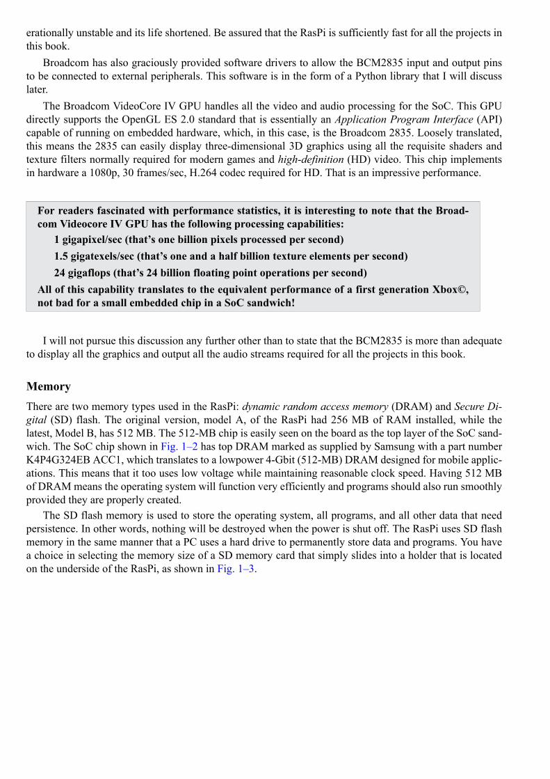
The SD flash memory is used to store the operating system, all programs, and all other data that needpersistence. In other words, nothing will be destroyed when the power is shut off. The RasPi uses SD flashmemory in the same manner that a PC uses a hard drive to permanently store data and programs. You havea choice in selecting the memory size of a SD memory card that simply slides into a holder that is locatedon the underside of the RasPi, as shown in Fig. 1–3.
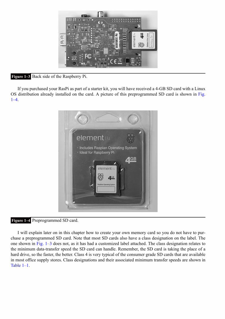
Figure 1–3 Back side of the Raspberry Pi.
If you purchased your RasPi as part of a starter kit, you will have received a 4-GB SD card with a LinuxOS distribution already installed on the card. A picture of this preprogrammed SD card is shown in Fig.1–4.
Figure 1–4 Preprogrammed SD card.
I will explain later on in this chapter how to create your own memory card so you do not have to pur-chase a preprogrammed SD card. Note that most SD cards also have a class designation on the label. Theone shown in Fig. 1–3 does not, as it has had a customized label attached. The class designation relates tothe minimum data-transfer speed the SD card can handle. Remember, the SD card is taking the place of ahard drive, so the faster, the better. Class 4 is very typical of the consumer grade SD cards that are availablein most office supply stores. Class designations and their associated minimum transfer speeds are shown inTable 1–1.

Table 1–1 SD Card Class Designations
What you should take away from this SD class discussion is that the higher the class number of the SDcard used in the RasPi, the better it will perform. The only downside is that SD cards with high class num-bers are more expensive than ones with lower numbers, sometimes more than twice the cost for the samestorage capacity. My only suggestion is to purchase a class 4 or higher; anything less and you will be disap-pointed in your RasPi’s slow response.
RasPi ConnectorsThe RasPi has nine connectors: power, High-Definition Multimedia Interface (HDMI), analog compositevideo, audio, ethernet, Universal Serial Bus (USB), two future expansion connectors, and the General Pur-pose Input/Output (GPIO) interface. Each connector has specific functions that I will discuss in the follow-ing sections, except for the expansion connectors, which are not yet used, although I will tell you what Iknow about them as of this writing. There is no particular order to this discussion although I have left theGPIO connector for last because it is by far the most complex and, hence, requires the most explanation.
Power ConnectorThe power connector shown in Fig. 1–5 is a micro USB socket that is wired to pass the 5-volt (V) directcurrent (DC) lines from a micro USB plug, also shown in the figure. (Since all voltage in this project is DC,I will use just the notation V for V DC.) No data connections are wired to this socket. You can use almostany available smartphone charger that has a micro USB connector or use the power supply that came withthe RasPi kit, if that’s what you purchased.
Figure 1–5 Micro USB power connector.

Figure 1–6 shows a RasPi kit power supply that is rated to supply 5 V at 1000 milliamperes (mA) or 1ampere (A). The regulatory compliance document supplied with this RasPi states the following:
Figure 1–6 External power supply.
This product shall only be connected to an external power supply rated at 5 V, and a minimumcurrent of 500–700 mA for model A and 700–1200 mA for model B.
I will have a bit more to say regarding current consumption when I discuss the USB connector.
HDMI ConnectorThe RasPi provides video and audio using a fully compliant HDMI, which is modern by most standards Theboard socket and sample cable plug are shown in Fig. 1–7.
Figure 1–7 HDMI connector and cable.
I have previously discussed the Broadcom GPU chip that controls the HDMI output. To keep thingssimple, the book projects will use only the “standard” type of audio/video output and will not take advantageof the true potential of the RasPi’s multimedia capabilities. Trust a fellow Evil Genius that you will be work-ing hard to complete the book projects without getting involved with HDMI development tasks.
One real problem that you will likely encounter is the lack of an HDMI input port for your computermonitor. This leaves you with three choices for observing the RasPi video:

1. Use the composite video output with a compatible analog monitor2. Use an adapter to convert from HDMI to Video Graphic Array (VGA) or Digital Video Interface (DVI)3. Take over the family’s flat panel digital TV
The first option is really not a very good choice, since the quality is diminished as compared to what isdisplayed by a high-quality computer monitor. The second option is the preferred method, as it yields thebest results using your existing computer resources. Choosing the third and final option will likely result infamily discord and upheaval for which I will take no responsibility!
The choice of an HDMI to VGA or HDMI to DVI adapter will, of course, depend upon what type ofmonitor input you have. Most monitors have a VGA input, and an adapter for that type of input is shown inFig. 1–8. The HDMI to DVI adapter is similar, and the cost for each is also similar.
Figure 1–8 HDMI to VGA adapter.
The HDMI connection also contains a very interesting surprise. The RasPi can act as a very soph-isticated remote control for HDMI-CEC compliant devices. The CEC suffix is short for Consumer Elec-tronics Control, which is a one-wire, bidirectional serial bus link protocol used for the control of audioand video devices. HDMI-CEC has been implemented by many A/V manufacturers including Sony withits Bravialink, LG with its Simplink, Sharp with its Aquos Link, Samsung with its Anynet+, and so on.The bad news is that there is currently no RasPi software support available for HDMI-CEC remote con-trol functions. The good news is to simply wait for a short time because new software apps are constantlybeing created, free of charge. By the time you are reading this, the RasPi should be able to turn yourdigital flat-panel TV on and off as well as control your A/V receiver, DVD player, Blu-Ray player,etc. The RasPi will become the ultimate remote control. For more information, go to http://elinux.org/CEC_(Consumer_Electronics_Control)_over_HDMI.
Analog Composite Video ConnectorThe RasPi also produces an analog video output from the RCA socket, as shown in Fig. 1–9.

Figure 1–9 Analog video connector and cable.
This analog video functionality was deliberately included in the RasPi design to accommodate all thosesituations where only analog monitors or analog TVs are available, especially in developing countries.There is, however, an upside to the composite output. To monitor project parameters in real time, you canuse small analog monitors. These monitors are fairly inexpensive and can often be battery powered, whichis not a realistic option with larger computer monitors. I have included the use of a small, battery-poweredanalog monitor in one of the book projects. This monitor is shown in Fig. 1–10.
Figure 1–10 Small analog video monitor.
Audio ConnectorThe RasPi is also capable of creating an analog audio output in full stereo. The output is from a standard3.5-mm stereo jack as shown in Fig. 1–11.

Figure 1–11 Analog audio connector and cable.
This audio would normally be the analog equivalent of the digital audio outputted from the HDMI con-nector. There is a book project that uses this analog output to play MP3 songs. You will need an audio amp-lifier to hear the music, as the RasPi does not generate a powerful enough signal to drive an unamplifiedspeaker. However, a good quality set of headphones will work.
Ethernet and USB ConnectorsBoth the Ethernet and USB connectors are shown in Fig. 1–12. I will discuss the Ethernet connector first,followed by the USB connectors.
Figure 1–12 Ethernet and USB connectors with cables.

The Ethernet connector shown on the left in the figure is a standard RJ45 connector. You would simplyplug your standard Ethernet patch cable into the socket and connect the other end to either your router orswitch, if that is the way you have setup your home network. The RasPi will then automatically “negotiate”with your router to gain an Internet Protocol (IP) address in a process known as Dynamic Host Configur-ation Protocol (DHCP). There are five light-emitting diodes (LEDs) to the left side of this socket as youlook at it head on. The LED furthest away from the socket is labeled “100.” If it is shining with a yellowlight, this means that a 100-megabits-per-second (Mb/s) connection was made. The next two LEDs, just tothe right of the 100 LED, are labeled “LNK” and “FDX”. These LEDs shine with green lights to indicatethat the Ethernet is alive and operating. Checking these LEDs is a quick way to determine if your Ethernetconnection is working or if something, somewhere, has gone down.
There is a stack of two USB connectors shown on the right-hand side of the figure. These are normalUSB connectors in the sense that USB peripherals will be recognized when plugged into the sockets. Theonly issue with these is that the RasPi cannot supply the standard amount of current according to the USBspecification, which is 500 mA per socket. Remember that I mentioned earlier in Fig. 1–6 that the powersupply in the RasPi kit provides up to 1000 mA. If peripherals plugged into these sockets took 500 mAeach, there would be none left for the poor RasPi! Obviously, this situation should not be allowed to happen,and there is a good and relatively cheap solution. I use a powered USB hub, as shown in Fig. 1–13, that caneasily provide all the current that typical unpowered USB peripherals require.
Figure 1–13 Self-powered USB hub.
There is one USB cable that connects between the hub and the RasPi. That leaves one available USBsocket on the RasPi for a low-power peripheral, such as a thumb drive. The number of USB ports providedby the hub varies with the manufacturer; however, four or five ports are fairly common. The power supplyshown in the figure is rated for 2100 mA, which precisely matches the USB specification for four ports anda little left over for the hub internal electronics.
Future Expansion ConnectorsTwo connectors prominently populated on the RasPi are not currently used. Referred to as “future expan-sion” connectors, they reflect the dynamic nature of the RasPi project. Fig. 1–14 is a close photo of oneof the connectors, labeled “S2.” This connector is a 15-way, flat-flex connector designated for use with theCamera Serial Interface (CSI-2). A prototype digital serial camera was just introduced at an internationalelectronics show at the time of this writing. The other flat-flex connector labeled “S5” and located just be-hind the Ethernet RJ45 connector is designated as a Display Serial Interface (DSI) that will eventually drivea Sony Low Voltage Differential Signaling (LVDS) serial display. You should check the RasPi website forthe latest news regarding the RasPi.

Figure 1–14 Expansion connectors.
GPIO Pin Interface ConnectorThe General Purpose Input Output (GPIO) connector has 26 pins positioned in two rows of 13 pins each.Fig. 1–15 shows this connector with pins 0, 1, 25, and 26 pointed out.
Figure 1–15 GPIO connector.
Table 1–2 details pin assignments with both the RasPi pin designations and the BMC2835 pin designa-tions. Using two different sets of pin designations is confusing, but unfortunately, that is the situation withthis board. I will try to use the RasPi pin designations whenever possible; however, there will be situationswhere the software will require the use of the BMC2835 pin designations. I will try to be as clear as possibleregarding the exact pin that is being used and for what purpose.

Table 1–2 GPIO Pin Descriptions
The Universal Asynchronous Receiver/Transmitter (UART), Serial Peripheral Interface (SPI), andInter-Integrated Circuit (I2C) functional pins listed in the table may all be reconfigured as GPIO pins. Theseare shown with an asterisk in Table 1–2. This means that up to 17 GPIO pins (8 existing GPIO + 9 reconfig-urable) are available for hardware interfacing, provided that the functions mentioned before are not needed.
Figure 1–16 shows all the GPIO connector pins with the BCM2835 pin designations. You should alwayscrosscheck your connections with this figure anytime that you are directly wiring to this connector.

Figure 1–16 GPIO connector pins with the BCM2835 pin designations.
CAUTION All GPIO voltage levels are 3.3 V, not 5 V tolerant. There is no overvoltage protection in-corporated on the RasPi; and if you inadvertently subject a GPIO pin to 5 V, you willwreck your RasPi. I will not take any responsibility for such foolish actions, as you havebeen warned!
I have incorporated hardware buffers into projects where 5-V sensors interface to the RasPi, thus avoid-ing any chance of damaging the RasPi due to an input voltage overload. You must always pay careful atten-tion to how the projects are wired because it is easy to damage the RasPi through an inadvertent construc-tion mistake.
Digital Signal Voltage LevelThe RasPi operates at a positive power-supply voltage (Vdd) of 3.3 V with the digital logic levels, shownin Table 1–3. This means that any GPIO input voltage greater than 2.7 V will be detected as a logical oneor HIGH. Any voltage input that is less than 0.7 V will be detected as a logical zero or LOW. However, theinput voltage can never exceed 3.3 V, or it will destroy the GPIO pin circuit.

Table 1–3 Digital Signal Voltage Levels
It turns out that standard 5-V logic accepts 3.3 V as a logical one or HIGH and anything less than 0.7 Vas a logical zero or LOW. This is exactly the reason that a RasPi can output to a 5-V logical device. The dif-ficulty happens if a 5-V device inputs into a GPIO pin. The 5-V logical device has the logic HIGH voltagerange of approximately 4.4- to 5-V that will immediately burn out the GPIO pin input circuitry.
Current LimitsThere are also some current draw limitations for both the 3.3-V and 5-V power pins. The limitations aredependent upon the RasPi model, as shown in Table 1–4.
Table 1–4 Raspberry Pi Current Consumption vs Model
Every GPIO pin can sink or source a limited amount of current ranging from 2 mA up to 16 mA. Thismeans that you must be very careful about the current demands put on the RasPi as well as how much cur-rent it will accept without causing problems.
GPIO Pin ExpansionRecently, the Raspberry Pi Foundation made a revision to the Model B that added access to some additionalGPIO pins that were not available in the earlier production run. This latest board is designated rev 2, whilethe earlier version is designated rev 1. The additional pins are plated PCB holes, as shown in Fig. 1–17, andare located next to the GPIO connector.
Figure 1–17 Additional GPIO pins available for expansion.

Table 1–5 shows all the additional pins with their RasPi and BMC designations. Pin 1 is the squareplated hole located in the upper left corner of P5. You will need to install a 12 pin connector to access thepins. The connector is supposed to be installed on the board’s underside per Note 3 on the rev 2.0 board’sschematic, which is available at http://www.raspberrypi.org/wp-content/uploads/2012/10/Raspberry-Pi-R2.0-Schematics-Issue2.2_027.pdf. A suggested connector is shown in Fig. 1–18. You will not need any ofthese additional pins from P5 to build any of the projects in this book.
Table 1–5 Additional GPIO Expansion Pins
Figure 1–18 GPIO pin expansion connector.
InterruptsEach GPIO pin can also accommodate what are known as interrupts. An interrupt is an event that stops or“interrupts” the normal programming flow and directs the microprocessor to execute some special handlerprogram, or code, for the interrupt source. Interrupts may be triggered in several ways:
HIGH level detectedLOW level detectedHIGH to LOW transition detectedLOW to HIGH transition detected
Using interrupts will certainly improve performance, but at the expense of adding a certain level of com-plexity to the software.
Serial ProtocolsThere are several serial protocols shown in the pin descriptions that I wish to discuss briefly.
SPI Serial Protocol
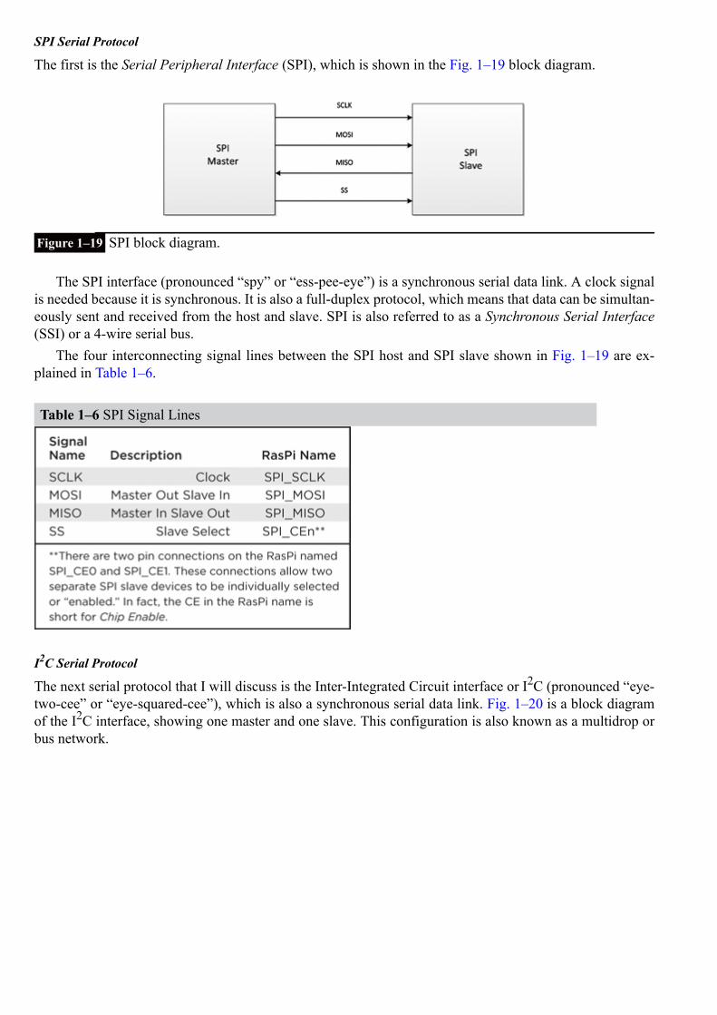
The first is the Serial Peripheral Interface (SPI), which is shown in the Fig. 1–19 block diagram.
Figure 1–19 SPI block diagram.
The SPI interface (pronounced “spy” or “ess-pee-eye”) is a synchronous serial data link. A clock signalis needed because it is synchronous. It is also a full-duplex protocol, which means that data can be simultan-eously sent and received from the host and slave. SPI is also referred to as a Synchronous Serial Interface(SSI) or a 4-wire serial bus.
The four interconnecting signal lines between the SPI host and SPI slave shown in Fig. 1–19 are ex-plained in Table 1–6.
Table 1–6 SPI Signal Lines
I2C Serial Protocol
The next serial protocol that I will discuss is the Inter-Integrated Circuit interface or I2C (pronounced “eye-two-cee” or “eye-squared-cee”), which is also a synchronous serial data link. Fig. 1–20 is a block diagramof the I2C interface, showing one master and one slave. This configuration is also known as a multidrop orbus network.
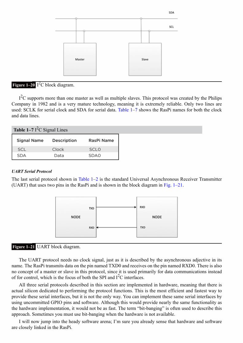
Figure 1–20 I2C block diagram.
I2C supports more than one master as well as multiple slaves. This protocol was created by the PhilipsCompany in 1982 and is a very mature technology, meaning it is extremely reliable. Only two lines areused: SCLK for serial clock and SDA for serial data. Table 1–7 shows the RasPi names for both the clockand data lines.
Table 1–7 I2C Signal Lines
UART Serial Protocol
The last serial protocol shown in Table 1–2 is the standard Universal Asynchronous Receiver Transmitter(UART) that uses two pins in the RasPi and is shown in the block diagram in Fig. 1–21.
Figure 1–21 UART block diagram.
The UART protocol needs no clock signal, just as it is described by the asynchronous adjective in itsname. The RasPi transmits data on the pin named TXD0 and receives on the pin named RXD0. There is alsono concept of a master or slave in this protocol, since it is used primarily for data communications insteadof for control, which is the focus of both the SPI and I2C interfaces.
All three serial protocols described in this section are implemented in hardware, meaning that there isactual silicon dedicated to performing the protocol functions. This is the most efficient and fastest way toprovide these serial interfaces, but it is not the only way. You can implement these same serial interfaces byusing uncommitted GPIO pins and software. Although this would provide nearly the same functionality asthe hardware implementation, it would not be as fast. The term “bit-banging” is often used to describe thisapproach. Sometimes you must use bit-banging when the hardware is not available.
I will now jump into the heady software arena; I’m sure you already sense that hardware and softwareare closely linked in the RasPi.

SoftwareThe RasPi was designed to be run with a Linux operating system. This design decision stands in stark con-trast to many other similar microprocessor boards, including the popular Arduino series, that do not operatein this fashion. This is not to imply that an Arduino board is inferior to the RasPi but simply to show thatusing the RasPi brings additional flexibility and capability to projects because of the Linux environment.
I will not start this discussion with a Linux tutorial, since there are many good Linux resources availableon the web. Google (or your favorite search engine) will turn up many hits regarding Linux tutorials. I willinstead use Linux commands and procedures, and explain them as I go along in a mentor capacity, as if Iwere standing beside you as you execute the commands. Additionally, I will be using the Python languageto program, or code, the RasPi and will provide more guidance regarding how Python works and how it isapplied with the RasPi, as it is the key to success in using the board and in understanding its operation withthe underlying project code.
Initial StartupA suggested RasPi setup that uses the connections discussed in the hardware section is shown in Fig. 1–22.This setup will be the basis for your projects once you add some prototyping hardware to the RasPi. Rightnow, I will be using the setup to get the RasPi configured in a proper manner to enable project development.You should connect all the components as shown in the figure, leaving the USB power connection for last.The RasPi will attempt to start up when the USB power cord is plugged in; and if you have not finishedconnecting all the other components, it is entirely possible that they will not be recognized in the startupsequence and your system will either not start or not operate correctly. I will also assume that you are usinga “prebuilt” Linux distribution that is provided with the RasPi starter kit or purchased separately. This 4 GBcard should also be plugged into the SD card holder prior to power being applied to the RasPi.
Figure 1–22 A suggested RasPi configuration.
CAUTION Inserting or removing an SD card while the RasPi is powered on is never a good idea. Badthings can happen including data corruption or worse.
Also, now would be a good time to skip down to the section that discusses how to load your own Linuxdistribution on an SD card if you did not purchase a starter kit or a “prebuilt” SD card.

You should see the initial configuration screen, shown in Fig. 1–23, on the monitor after you connect theUSB power to the RasPi. Please be patient; it takes a while. You will at first see a massive amount of textscrolling by on the screen, which will make absolutely no sense to you if you are not familiar with Linux.
Figure 1–23 Raspberry Pi configuration screenshot.
Suggested configuration settings are shown in Table 1–8 along with some comments regarding why aparticular setting was selected.
Table 1–8 Suggested Configuration Settings
After you finish the configuration, the monitor prompt will eventually show. It is waiting for you toenter the user name, which is pi.
Next, the password prompt shows Password:. Enter raspberry.

Please note I am not giving away any secrets, as every unmodified RasPi Linux distribution is createdwith this default password. You may have changed it in the configuration menu; if so, enter that password.
Next type startx and press Enter.
This will create the GUI desktop, as shown in Fig. 1–24.
Figure 1–24 Raspberry Pi GUI desktop.
Congratulations, it is now about 15 pages into the book, and you now have the first indication that youhave a working and useful Linux computer. Fear not; progress will be much faster from now on. To partiallyaccomplish this goal, I will minimize the number of screenshots and simply use text to show you what toenter and how the computer responds.
Preparing your own SD card using a Windows PCYou will need two items other than the card itself. First you will need to download and install a programnamed win32diskimager.exe. This program is available at http://sourceforge.net/projects/win32diskimager/.The file is in a compressed Zip format from which you have to extract the program before running it. Notethat in spite of the win32 in the name, this app works without a problem on my Win7, 64-bit laptop.
The second item you will need is the image file for the RasPi Linux distribution that you desire to install.The current version, at the time of this writing, may be downloaded from the main Raspberry Pi website ht-tp://downloads.raspberrypi.org/images/raspbian/2012-10-28-wheezy-raspbian/2012-10-28-wheezy-raspbi-an.zip. It is a very large Zip file (647 MB) from which the Linux distribution must be extracted before it canbe used as a disk image file. The Raspberry Pi Foundation currently appears to be updating the Wheezy-Raspian Linux distribution almost every month. This is subject to change, so take advantage of it while itlasts.
It is now a simple matter to create your own SD card once you have the image and the disk writer pro-gram. Insert a blank SD card into the PC, run the app, and then browse to the location where the image isstored. Then click on Write, and you will get a warning about destroying existing data on the card. ClickOK and wait. It takes several minutes to create the image. You now have your own Linux distribution on an

SD card. Also, remember that you can rewrite an SD card as often as you want, so feel free to experimentwith different distributions.
I now need you to create a new SD card, both to ensure that you understand this process and that youhave a specific distribution available that will also support the Chap. 10 book project, which requires whatis known as the “1-Wire” serial protocol. This distribution is named Occidentalis V0.2 and is availableat http://learn.adafruit.com/adafruit-raspberry-pi-educational-linux-distro/occidentalis-v0-dot-2. This distri-bution was created by the kind folks at Adafruit, where I purchase most of my RasPi goodies. The unusualname derives from the Latin name Rubus Occidentalis for the black raspberry, which is apparent from theGUI desktop that appears when this distribution is running, as shown in Fig. 1–25.
Figure 1–25 Occidentalis GUI desktop.
Some Linux FundamentalsAs I promised you earlier, I am not going to provide a tutorial on Linux in this book. However, you will stillneed to have some very basic knowledge of it to understand what is happening with the commands beingprocessed. The discussion below is for readers with a very limited knowledge of Linux. Feel free to skipthis section if you already have a basic to good understanding of Linux.
The Linux operating system is based upon Unix, and it has assigned built-in privileges, which limit mostusers to some extent but allow one user unlimited access. This unlimited user is named root and essentiallyis equivalent to an administrator level in a Windows operating system. Some commands can be run or ex-ecuted only by root, again for security reasons. There is a fundamental computer security principle knownas “least privilege” by which users are granted only as much access or privilege as they need to completetheir task.
It is not considered a good idea to run all tasks or programs as root, so most of the time you will berunning as the user named pi. However, as I mentioned earlier, some commands can only be run as root.The answer to this conundrum is to “promote” an ordinary user to what is known as a super user. The sudocommand accomplishes this neat feat. I will frequently use the sudo command with other commands, andyou now know why.
I will also typically use terminal windows to execute commands, as most of the time I will have theGUI desktop running. There are two flavors of terminal windows available, the Lightweight X11 DesktopEnvironment (LXDE) for normal users and a root level terminal. The only effective difference between theterminal windows is that I have to type sudo in the LXDE terminal while this is not required in the rootterminal, since it already operates at that level.
You will also need to create some Python code to program the RasPi. I use a very simple but effectivetext editor named nano. All you need to run the editor is to open a terminal window and type nanotest_my_project.py if you wanted to either create or open an existing file named test_my_project.py.The editor program has all the important commands listed at the bottom of the editor window. For example,
to save the editor buffer, you have to press and hold the control key while simultaneously pressing the “o”key. This is shown as ^o on the help screen.
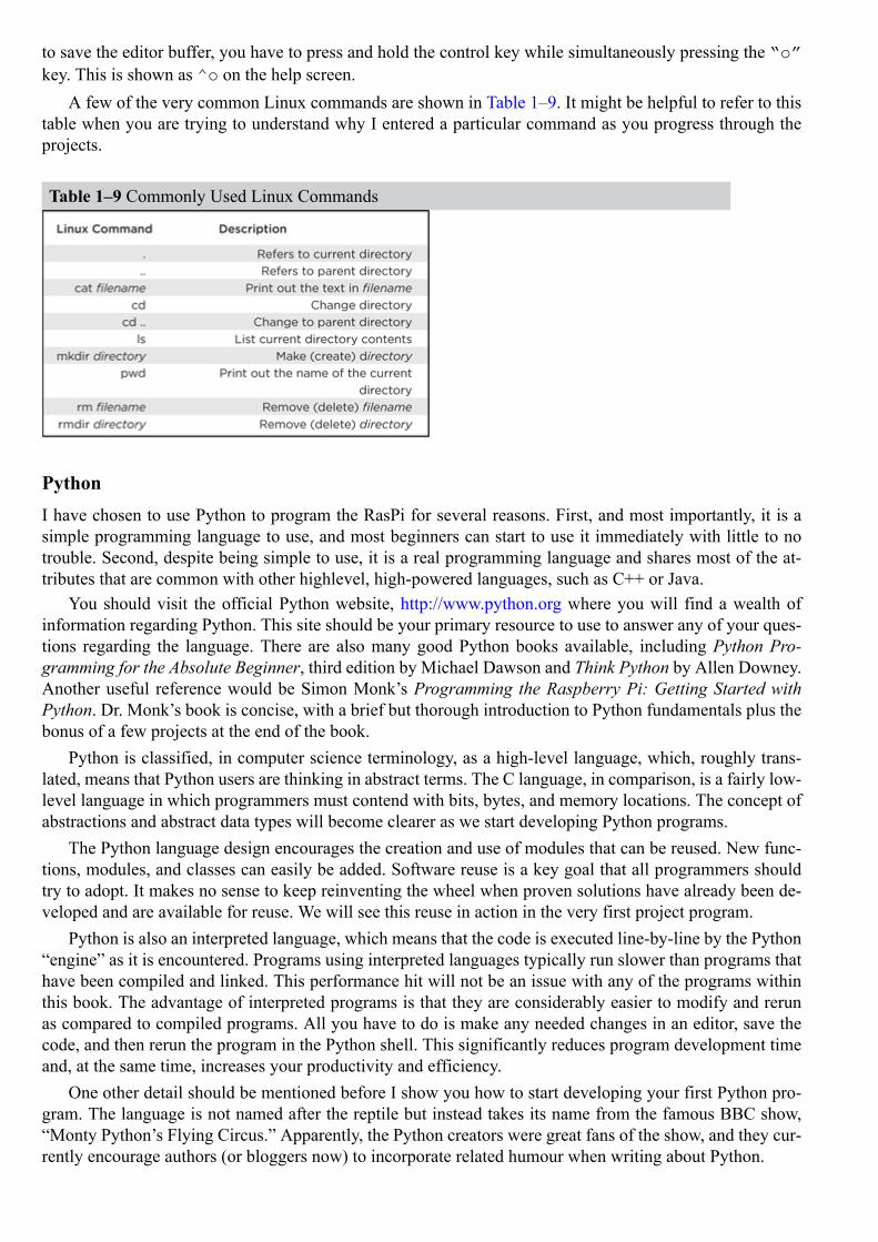
A few of the very common Linux commands are shown in Table 1–9. It might be helpful to refer to thistable when you are trying to understand why I entered a particular command as you progress through theprojects.
Table 1–9 Commonly Used Linux Commands
PythonI have chosen to use Python to program the RasPi for several reasons. First, and most importantly, it is asimple programming language to use, and most beginners can start to use it immediately with little to notrouble. Second, despite being simple to use, it is a real programming language and shares most of the at-tributes that are common with other highlevel, high-powered languages, such as C++ or Java.
You should visit the official Python website, http://www.python.org where you will find a wealth ofinformation regarding Python. This site should be your primary resource to use to answer any of your ques-tions regarding the language. There are also many good Python books available, including Python Pro-gramming for the Absolute Beginner, third edition by Michael Dawson and Think Python by Allen Downey.Another useful reference would be Simon Monk’s Programming the Raspberry Pi: Getting Started withPython. Dr. Monk’s book is concise, with a brief but thorough introduction to Python fundamentals plus thebonus of a few projects at the end of the book.
Python is classified, in computer science terminology, as a high-level language, which, roughly trans-lated, means that Python users are thinking in abstract terms. The C language, in comparison, is a fairly low-level language in which programmers must contend with bits, bytes, and memory locations. The concept ofabstractions and abstract data types will become clearer as we start developing Python programs.
The Python language design encourages the creation and use of modules that can be reused. New func-tions, modules, and classes can easily be added. Software reuse is a key goal that all programmers shouldtry to adopt. It makes no sense to keep reinventing the wheel when proven solutions have already been de-veloped and are available for reuse. We will see this reuse in action in the very first project program.
Python is also an interpreted language, which means that the code is executed line-by-line by the Python“engine” as it is encountered. Programs using interpreted languages typically run slower than programs thathave been compiled and linked. This performance hit will not be an issue with any of the programs withinthis book. The advantage of interpreted programs is that they are considerably easier to modify and rerunas compared to compiled programs. All you have to do is make any needed changes in an editor, save thecode, and then rerun the program in the Python shell. This significantly reduces program development timeand, at the same time, increases your productivity and efficiency.
One other detail should be mentioned before I show you how to start developing your first Python pro-gram. The language is not named after the reptile but instead takes its name from the famous BBC show,“Monty Python’s Flying Circus.” Apparently, the Python creators were great fans of the show, and they cur-rently encourage authors (or bloggers now) to incorporate related humour when writing about Python.

IDLEIDLE is the name of an application that creates and runs the shell environment that I will use to develop andtest your Python programs. Fig. 1–26 shows a portion of the desktop with two IDLE icons appearing.
Figure 1–26 IDLE desktop icons.
The top icon opens a Python version 3 shell, while the icon directly underneath opens a Python version2 shell. I will be using the version 2 shell, as that Python version is compatible with the software librariesthat are needed to run the hardware used in the projects.
User interaction using the Python shell is intuitive; results are instantly displayed after an operation isperformed and the Enter key is pressed. Adding 7 + 5 with the sum displayed below the input numbers isshown in Fig. 1–27.

Figure 1–27 A simple Python operation.
Displaying text in the Linux shell is also easy to accomplish; simply use the print function. Traditionally,the first program to be run in most programming books is the so-called “Hello World” program. I do notlike to trifle with tradition and will adhere to this unwritten rule. Now it is perfectly possible to execute theprint command and see Hello World displayed below, as is shown in Fig. 1–28.
Figure 1–28 Python print command.
As this book is printed in monochrome, I will point out the following as you observe the output in thePython shell. The word print is reddish-orange, as it is a reserved word describing a preset function. Thewords Hello World in the parentheses following the print function are shown in green to indicatea string of characters. Character strings are enclosed between single quotes. Finally, the words HelloWorld displayed below the print function are in blue, as they represent a string output. This defaultcolor coding of program code is fairly standard with various development tools; however, the exact colorsassigned to the different elements will vary.
From this point on, I will now use text only to show the shell prompt, commands, operations, and resultsto conserve valuable book space. You should also carefully observe the Linux shell because there may beinformation shown that I do not transcribe.
I will now show you how to create a very simple program that produces the same result as discussedabove. I will use the nano editor to write the program and save it. I will then recall the saved program andrun it from the Linux shell.
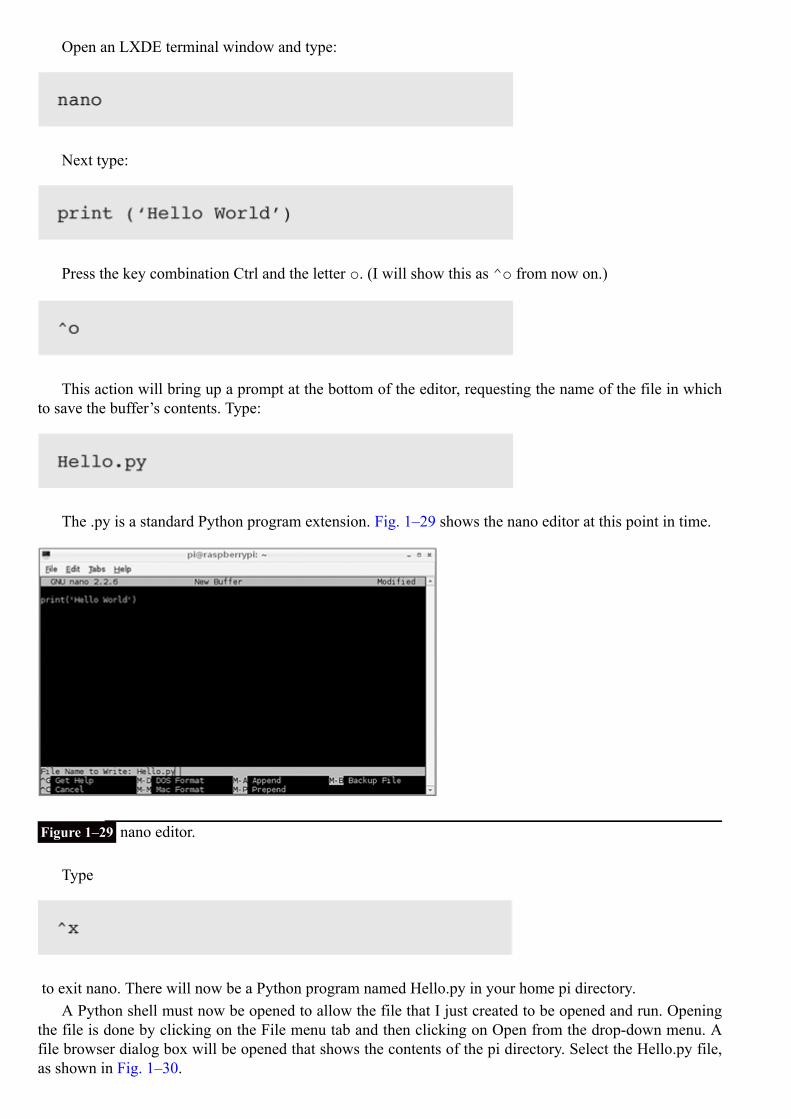
Open an LXDE terminal window and type:
Next type:
Press the key combination Ctrl and the letter o. (I will show this as ^o from now on.)
This action will bring up a prompt at the bottom of the editor, requesting the name of the file in whichto save the buffer’s contents. Type:
The .py is a standard Python program extension. Fig. 1–29 shows the nano editor at this point in time.
Figure 1–29 nano editor.
Type
to exit nano. There will now be a Python program named Hello.py in your home pi directory.A Python shell must now be opened to allow the file that I just created to be opened and run. Opening
the file is done by clicking on the File menu tab and then clicking on Open from the drop-down menu. Afile browser dialog box will be opened that shows the contents of the pi directory. Select the Hello.py file,as shown in Fig. 1–30.

Figure 1–30 Opening a file in the Python shell.
Selecting the Hello.py file will cause a second window to appear on the desktop with the contents ofHello.py shown in the window. This is very convenient in that you can modify the file contents without af-fecting any of the content happening in the Python shell. To execute the program, you must be in the secondwindow that was just opened where you can either open the Run menu tab and select Run or simply pressthe F5 function key. The Hello.py program results appear in the Python shell, as can be clearly seen in Fig.1–31.
Figure 1–31 Running a program from the Python shell.
SummaryI have covered a lot of material in this chapter, from introducing the RasPi and a bit of its history to ex-plaining the role that its inventors would like it to fulfill. I also covered the hardware aspects, as you need to

understand the design decisions that went into the RasPi and the consequent constraints and attributes thatyou must consider when incorporating this board into a real world project.
A brief Linux introduction was covered to get you started in using this great operating system. Mostpeople find that once they become proficient in using Linux, especially at the command-line level, theylook at MS Windows with a newfound disdain. I am not pooh-poohing Windows; I am simply saying thatLinux gives you much greater control of your programming environment than you could achieve by usingWindows.
Next I discussed Python and demonstrated how simple it is to start programming the RasPi with the tra-ditional “Hello World” program. Using the Python shell named IDLE just makes the whole effort very easyand, I hope, enjoyable.
CHAPTER 2
LED Blinker Project
Now we start creating projects using the RasPi. However, I still have some preparatory steps to discuss and inform-ation to provide about the prototype board that will be used in this and other projects. I will also present a detaileddiscussion of the GPIO library, which is critical to making all of the projects work. The first project will consist ofturning on an LED connected to a GPIO pin and then causing that LED to blink.
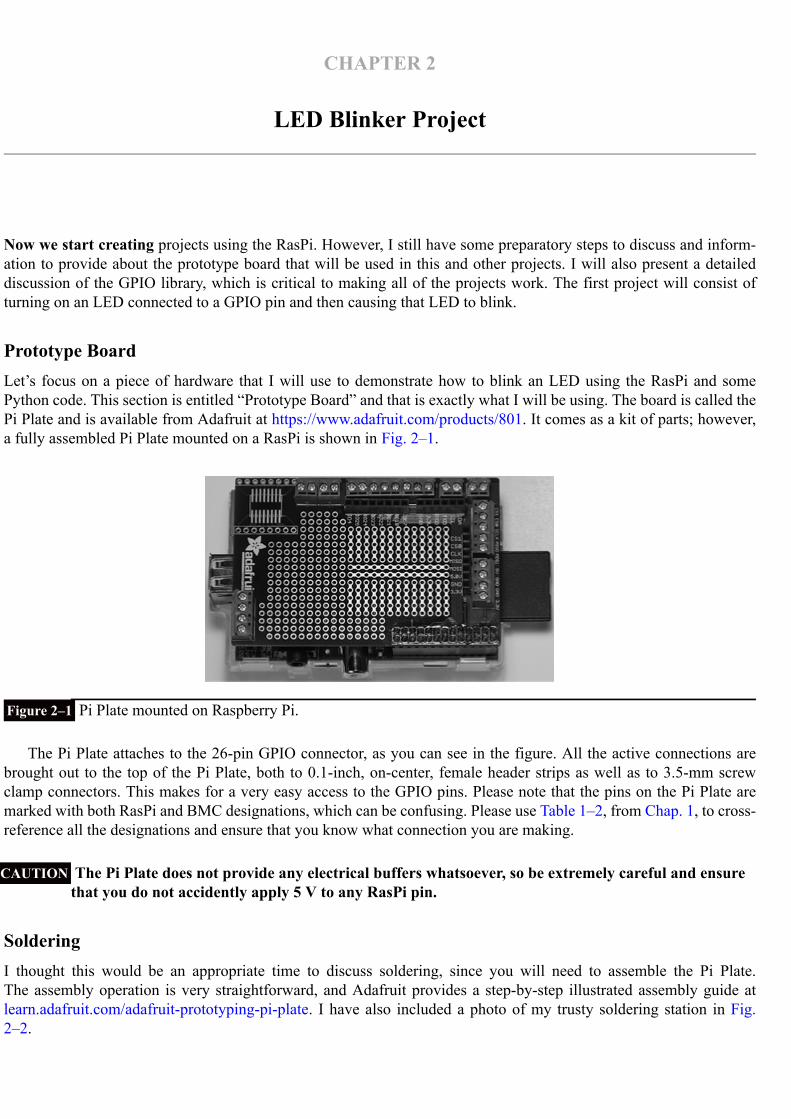
Prototype BoardLet’s focus on a piece of hardware that I will use to demonstrate how to blink an LED using the RasPi and somePython code. This section is entitled “Prototype Board” and that is exactly what I will be using. The board is called thePi Plate and is available from Adafruit at https://www.adafruit.com/products/801. It comes as a kit of parts; however,a fully assembled Pi Plate mounted on a RasPi is shown in Fig. 2–1.
Figure 2–1 Pi Plate mounted on Raspberry Pi.
The Pi Plate attaches to the 26-pin GPIO connector, as you can see in the figure. All the active connections arebrought out to the top of the Pi Plate, both to 0.1-inch, on-center, female header strips as well as to 3.5-mm screwclamp connectors. This makes for a very easy access to the GPIO pins. Please note that the pins on the Pi Plate aremarked with both RasPi and BMC designations, which can be confusing. Please use Table 1–2, from Chap. 1, to cross-reference all the designations and ensure that you know what connection you are making.
CAUTION The Pi Plate does not provide any electrical buffers whatsoever, so be extremely careful and ensurethat you do not accidently apply 5 V to any RasPi pin.
SolderingI thought this would be an appropriate time to discuss soldering, since you will need to assemble the Pi Plate.The assembly operation is very straightforward, and Adafruit provides a step-by-step illustrated assembly guide atlearn.adafruit.com/adafruit-prototyping-pi-plate. I have also included a photo of my trusty soldering station in Fig.2–2.
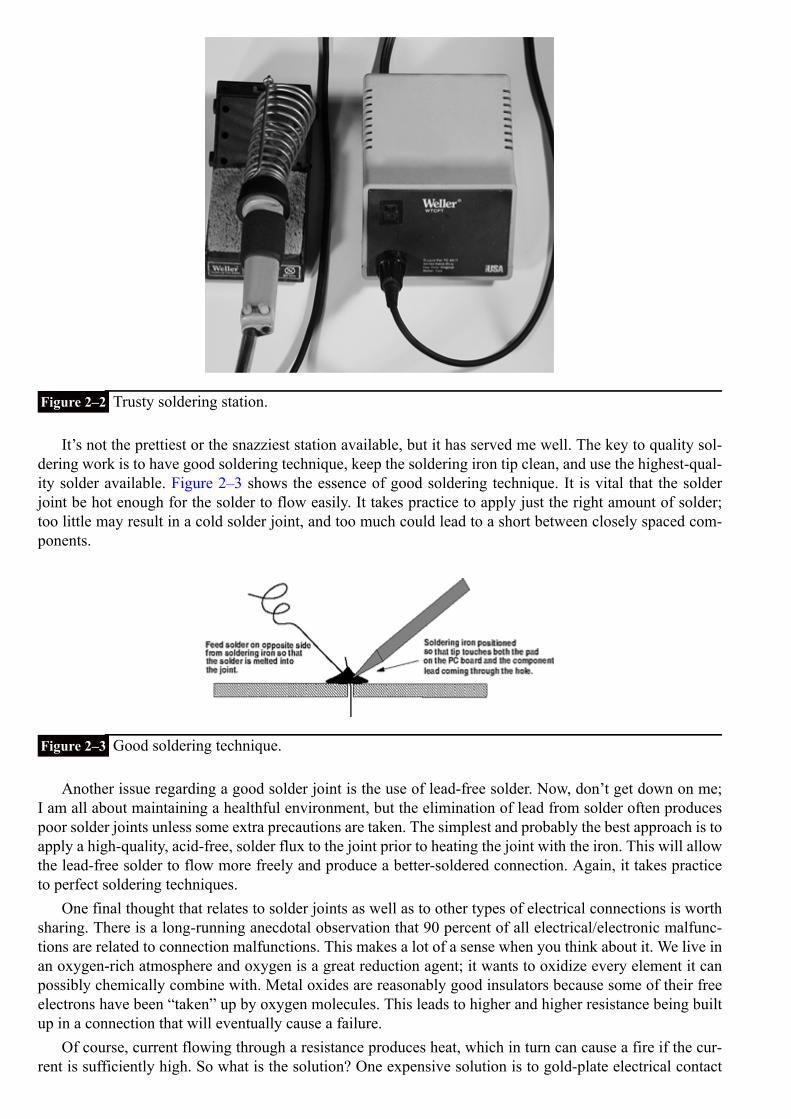
Figure 2–2 Trusty soldering station.
It’s not the prettiest or the snazziest station available, but it has served me well. The key to quality sol-dering work is to have good soldering technique, keep the soldering iron tip clean, and use the highest-qual-ity solder available. Figure 2–3 shows the essence of good soldering technique. It is vital that the solderjoint be hot enough for the solder to flow easily. It takes practice to apply just the right amount of solder;too little may result in a cold solder joint, and too much could lead to a short between closely spaced com-ponents.
Figure 2–3 Good soldering technique.
Another issue regarding a good solder joint is the use of lead-free solder. Now, don’t get down on me;I am all about maintaining a healthful environment, but the elimination of lead from solder often producespoor solder joints unless some extra precautions are taken. The simplest and probably the best approach is toapply a high-quality, acid-free, solder flux to the joint prior to heating the joint with the iron. This will allowthe lead-free solder to flow more freely and produce a better-soldered connection. Again, it takes practiceto perfect soldering techniques.
One final thought that relates to solder joints as well as to other types of electrical connections is worthsharing. There is a long-running anecdotal observation that 90 percent of all electrical/electronic malfunc-tions are related to connection malfunctions. This makes a lot of a sense when you think about it. We live inan oxygen-rich atmosphere and oxygen is a great reduction agent; it wants to oxidize every element it canpossibly chemically combine with. Metal oxides are reasonably good insulators because some of their freeelectrons have been “taken” up by oxygen molecules. This leads to higher and higher resistance being builtup in a connection that will eventually cause a failure.
Of course, current flowing through a resistance produces heat, which in turn can cause a fire if the cur-rent is sufficiently high. So what is the solution? One expensive solution is to gold-plate electrical contact

surfaces. Gold does not oxidize and is not subject to this type of failure. It is, of course, very expensive andnot practical for large-scale connectors. Another solution that the power industry employs is what is knownas gastight connections, which require the use of special components and specialized training to produce.For the type of projects that I work on, I can only ensure that the solder joints are sound from both a mech-anical and an electrical perspective. I also inspect electrical connections for oxidation and foreign matterand take appropriate action to replace the compromised connection or component.
Accessing the GPIO PinsThe GPIO pins have to be made programmable in order to blink the LED. Being made programmable meansthat the pins are set to either sense an input voltage or set an output voltage. The pins are accessed by using ahigh-level name such as pin (18) that you can readily identify—in this case, GPIO pin number 18. We mustuse a software library that contains the required high-level abstractions and hardware associations to enableus to control the GPIO pins with a Python program. This library is named Rpi.GPIO-0.4.1a.tar.gz and isreadily available as a Linux archived file from http://code.google.com/p/raspberry-gpio-python/downloads/list. Figure 2–4 shows this website.
Figure 2–4 GPIO library download website.
The archived file must be downloaded, extracted, and stored in an appropriate directory. I would suggestcreating a new directory named Python located in the pi parent directory.
Open an LXDE terminal window and type the following commands in the terminal window:

You should now be in your development directory, Python, ready to download the GPIO library archive.You have several choices on how to download the archive file. You can use a browser on the RasPi and justdo a direct download, or you can use a PC and download it into a thumb drive, which you then carry over tothe RasPi and transfer it using the File Manager app. I choose to do the latter as the PC download process ismuch faster. In days of “yore” this approach was called the “sneakernet”.
The archive must now be uncompressed and the contents extracted. Assuming you are still using a ter-minal window in the Python directory, type the following:

Ensure that you type in the exact name with uppercase and lowercase letters as shown. Linux is verypicky in this regard and will throw an error message that it cannot find the file if you don’t enter the nameexactly as it appears. The tar app will create a new directory named RPi.GPIO-0.4.1a, where you will findover a dozen files and directories newly created. Type the following to transfer into this directory.
Incidentally, I will no longer explicitly show these commands, as you should now be more comfortableusing them. I will instead simply say cd into RPi.GPIO-0.4.1a, and you will instantly know what Imean.
Let’s test this newfound confidence! ls the RPi.GPIO-0.4.1a directory. You should now be look-ing at a list of all the files and subdirectories. One file should pique your interest; it is named INSTALL.txt.cat this file to read the contents. You could also double click on it to open it in a text editor, but I am feelingconfident that you are starting to get the feel of how to operate quickly and efficiently at the command-linelevel, where the pros live. Back to the INSTALL.txt file. It contains important instructions regarding load-ing another module required to use the GPIO library. The key instruction is the following:
Please read the following section before you enter the above command.
apt-get CommandThe acronym apt is short for advanced packaging tool. You almost always use the command in the form ofapt-get for instructing the computer to “get” a package of software using the Internet. The key to mak-ing this all work is a list of repositories that apt refers to in order to retrieve the requested package. Therepository list is located at /etc/apt/sources.list in the Linux distribution.
The apt-get command also wants to know what you want done with the software package once ithas been retrieved. That’s the purpose of the install portion of the command. But apt has other neatfeatures including the ability to update all the packages already installed in the computer. Simply type thefollowing:
All available updates for installed packages will now be installed. Be patient; this will take a while, es-pecially if there are many packages involved.
However, that’s not all apt is capable of doing on a “global” scale. You can upgrade all your installedpackages, provided upgrades are available. Type the following:

Upgrades as the name implies are new versions of installed packages. You should always update priorto upgrading in order to lessen the chance that an inappropriate update will be applied to a newer version.
There is a great deal of information available on apt at www.debian.org/doc/user-manuals#apt-howto.
LED ProjectI will now show you the LED project that ties together all the information that you have carefully studied sofar . I will create a program to turn on an LED connected to pin 18 using the Pi Plate as a prototype aid. Youwill need a little information on how to connect the LED and limit the current flowing through the device.Figure 2–5 is a diagram showing the LED connections as well some physical descriptions that should behelpful to you in understanding the circuit.
Figure 2–5 Diagram illustrating LED connection to the Pi Plate.
The LED anode has a longer lead that is connected to the pin 18 screw terminal. The LED’s shorter leadis the cathode, and it is connected to one lead of the 570-ohm (Ω) resistor. The other resistor lead is connec-ted to the ground screw terminal. The resistor’s value was calculated as follows:
Current range that a RasPi pin can handle is 2 mA to 16 mA. So, 5 mA was selected as a low- to mid-range value with just enough current to operate the LED with a dim red light. No sense in overstressingthe RasPi.The high output voltage from pin 18 is 3.3 V. The LED has a nominal drop of 0.7 V. Therefore, 3.3 – 0.7or 2.6 V must be dropped with a 5 mA current.Ohm’s law: R = E/I where R stands for the resistance of a conductor in ohms, E stands for the potentialdifference across a conductor in volts, and I stands for the current through a conductor in amperes .Plugging in the values for E and I, we get 2.6 V/(5 mA ÷ 1000) = 520 Ω resistance. Note that the 5 mAhad to be converted to amperes by dividing by 1000.570 Ω is the nearest standard value resistor to 520 Ω.
Figure 2–6 shows the actual connections. I simply twisted the cathode lead to a resistor lead andsoldered them to ensure a good connection.
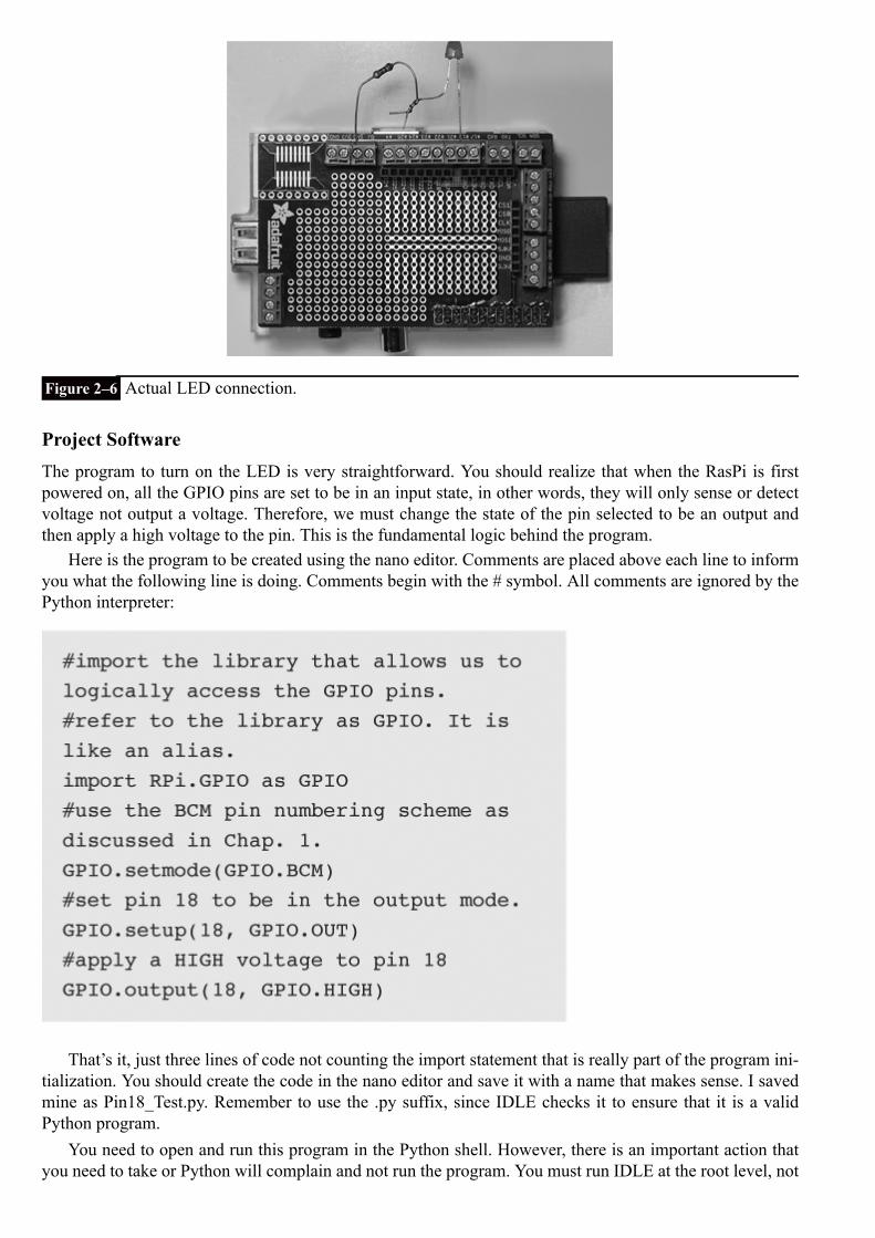
Figure 2–6 Actual LED connection.
Project SoftwareThe program to turn on the LED is very straightforward. You should realize that when the RasPi is firstpowered on, all the GPIO pins are set to be in an input state, in other words, they will only sense or detectvoltage not output a voltage. Therefore, we must change the state of the pin selected to be an output andthen apply a high voltage to the pin. This is the fundamental logic behind the program.
Here is the program to be created using the nano editor. Comments are placed above each line to informyou what the following line is doing. Comments begin with the # symbol. All comments are ignored by thePython interpreter:
That’s it, just three lines of code not counting the import statement that is really part of the program ini-tialization. You should create the code in the nano editor and save it with a name that makes sense. I savedmine as Pin18_Test.py. Remember to use the .py suffix, since IDLE checks it to ensure that it is a validPython program.
You need to open and run this program in the Python shell. However, there is an important action thatyou need to take or Python will complain and not run the program. You must run IDLE at the root level, not
at a “normal” user level. This is needed, I believe, because the GPIO library is accessing Linux functions orresources that can only be accessed as root. Do the following to run the IDLE Linux shell as root:
Open a terminal window and type:
That is all that’s needed, and you will be at the exact place where you can open and run your program,as discussed in a previous section. Running the program will turn on the LED; not very exciting so far, asour journey begins with small steps. The next section shows you how to blink the LED.
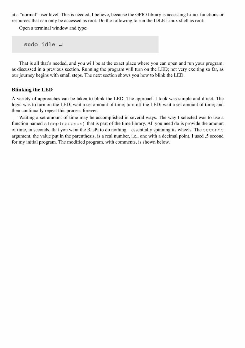
Blinking the LEDA variety of approaches can be taken to blink the LED. The approach I took was simple and direct. Thelogic was to turn on the LED; wait a set amount of time; turn off the LED; wait a set amount of time; andthen continually repeat this process forever.
Waiting a set amount of time may be accomplished in several ways. The way I selected was to use afunction named sleep(seconds) that is part of the time library. All you need do is provide the amountof time, in seconds, that you want the RasPi to do nothing—essentially spinning its wheels. The secondsargument, the value put in the parenthesis, is a real number, i.e., one with a decimal point. I used .5 secondfor my initial program. The modified program, with comments, is shown below.
While you can make the modifications to the original program using the nano editor, I found it moreconvenient to use the shell editor, which displays the program when you first open it. This editor will allowyou to save the program with the original or a new name.
There are a few items in the program that should be explained. The time library is accessed by using theimport statement, the same way the GPIO library was accessed.
The looping behavior is imposed by two things; First, I used what is known as a conditional statement,while True. The while portion of this statement checks what immediately follows it, and if the expres-sion evaluates to a logical True, will loop or repeat all statements below the conditional that are indentedat least four spaces. The logical value of True that follows the while statement thus causes the looping tocontinue forever.
Pausing the program is a result of calling or invoking the sleep function, a part of the time library.The actual call is the statement time.sleep(.5). This is not the first time you have seen this calltype; I used it several times in the original program, i.e., GPIO. setup(18, GPIO.OUT). The periodin the statements represents a special operator known as the “member of” operator. Restating the time.sleep(.5) call with this operator translates to “call the sleep function that is a member of the time librarywith an argument of .5.” Don’t worry if this discussion is somewhat confusing; all I am trying to do is togently introduce you to the concept of object-oriented programming, something that I will pursue in laterchapters.

Now back to the Blinker program. Make the modifications to the original program and then run it. Youshould be rewarded with a blinking LED for all your efforts. Congratulations! Show all your family andfriends!
SummaryI started this chapter with a discussion on the Pi Plate prototype plate that serves as an excellent projectexperimental platform. Next, I briefly mentioned some good soldering tips that have helped me over theyears. Next, there was the discussion regarding the GPIO library that may have overwhelmed some of youa bit, but that was necessary in order to set the stage for the LED project. The good news is that we willsimply use the GPIO library from this point on in various projects. That’s software reuse at its best. The lastsections of this chapter focused on a real world project of first turning on an LED and then blinking thatsame LED.
Now we move on to bigger, better, and more interesting projects. And yes, you will still learn and gathera good education as you progress through the remaining projects.

CHAPTER 3
MP3 Player Project
In this project, I will show you how to create a fairly simple, yet fully functional, MP3 audio player. I will also de-scribe how to use the GPIO pins as inputs, which will allow the player to use some hardware push-button switches toselect the MP3 songs it will play.
We will also explore the Advanced Linux Sound Architecture (ALSA) software package that drives the Linux soundproduction and provides some utilities essential to helping us complete this project.
Prototype ConnectorLet’s first focus on a piece of hardware that I will use to connect the project hardware switches with the RasPi’s GPIOpins. This prototype aid is different from the Pi Plate introduced in the last chapter. Called the Pi Cobbler, it is shownin Fig. 3–1 without the interface ribbon connector in order to show all the pins clearly.
Figure 3–1 Pi Cobbler prototype connector.
Really just a direct extension of, or a breakout kit for, the GPIO connector, it allows all the pins to be connectedto a solderless breadboard. It is available as a kit from a variety of sources, including Adafruit at www.adafruit.com/products/914. A fully assembled Pi Cobbler mounted on a breadboard and connected to a RasPi is shown in Fig. 3–2.

Figure 3–2 Pi Cobbler on a solderless breadboard connected to a Raspberry Pi.
Using the Pi Cobbler along with the breadboard will allow for rapid project construction and easy modi-fications to the existing project. It will help you to have a variety of prestripped wire available to use withthe breadboard. You can either make your own using 22-gauge, solid pickup wire or purchase a packagefrom your favorite electronics components supplier. Figure 3–3 shows a package that I bought for the bookprojects. These wires are actually stranded for flexibility and are also terminated with a solid, insulated pinconnection. It is well worth the cost to buy a kit of these wires.
Figure 3–3 High-quality breadboard interconnect wires.
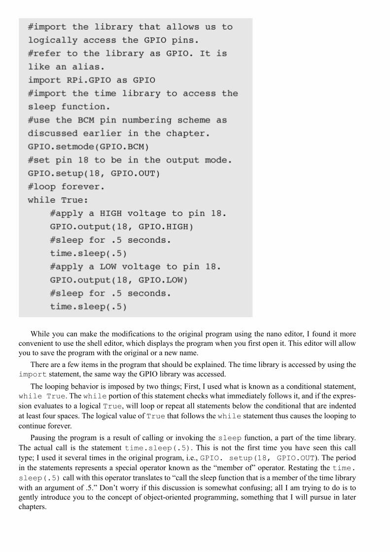
Portable Stereo SpeakerYou will need a way to listen to the MP3 recordings. I use the very small and inexpensive stereo speakerdevice, the Veho360 (www.veho-uk.com) that is shown in Fig. 3–4.
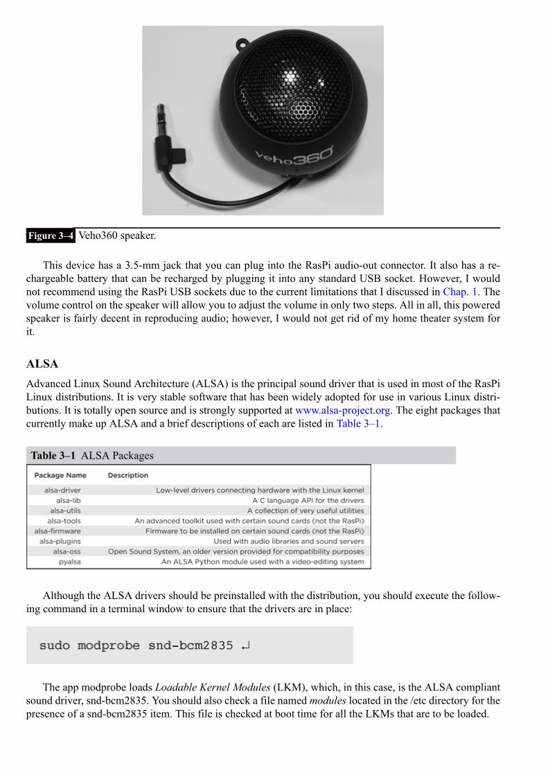
Figure 3–4 Veho360 speaker.
This device has a 3.5-mm jack that you can plug into the RasPi audio-out connector. It also has a re-chargeable battery that can be recharged by plugging it into any standard USB socket. However, I wouldnot recommend using the RasPi USB sockets due to the current limitations that I discussed in Chap. 1. Thevolume control on the speaker will allow you to adjust the volume in only two steps. All in all, this poweredspeaker is fairly decent in reproducing audio; however, I would not get rid of my home theater system forit.
ALSAAdvanced Linux Sound Architecture (ALSA) is the principal sound driver that is used in most of the RasPiLinux distributions. It is very stable software that has been widely adopted for use in various Linux distri-butions. It is totally open source and is strongly supported at www.alsa-project.org. The eight packages thatcurrently make up ALSA and a brief descriptions of each are listed in Table 3–1.
Table 3–1 ALSA Packages
Although the ALSA drivers should be preinstalled with the distribution, you should execute the follow-ing command in a terminal window to ensure that the drivers are in place:
The app modprobe loads Loadable Kernel Modules (LKM), which, in this case, is the ALSA compliantsound driver, snd-bcm2835. You should also check a file named modules located in the /etc directory for thepresence of a snd-bcm2835 item. This file is checked at boot time for all the LKMs that are to be loaded.

You also need to install the alsa-utils package as that contains several apps that are important to get ourproject working. The installation uses the aptget command that was discussed in Chap. 1. Type the fol-lowing command in a terminal window:
One more step is required to ensure that sound is produced at the analog audio jack. Type the followingin a terminal window:
The app amixer is part of the alsa-utils package that allows us to select the desired audio output con-nector. The HDMI is the default audio output device when the RasPi is first booted. The audio output isredirected using the above command. The number at the end of the above command line represents the fol-lowing:
0—auto
1—analog
2—HDMI
Testing the Analog Audio
Now, it is time to test the audio from the RasPi. Connect a powered speaker to the 3.5-mm jack and type thefollowing in a terminal window:
You should now be hearing a rushing noise from the speaker. This is a pink-noise signal being createdby the speaker-test app that is part of the ALSA package. (For a more detailed explanation of pink noise,see the following section on Analog Audio Frequency Response.) If you do not hear this noise, reviewthe commands listed above and ensure that they were entered as shown. The speaker-test app has manymore options than just producing a noise output. Go to http://manpages.ubuntu.com/manpages/natty/man1/speaker-test.1.html for more information.
Analog Audio Frequency Response
Having a pink noise output provides an unexpected opportunity to measure the frequency response of theRasPi analog audio system. I have had many years of experience as an acoustical engineer, and to me, thisseemed a natural opportunity to assess the acoustic performance with this particular subsystem. First, let usdelve into a bit of background information regarding pink noise and why it is so useful in determining asystem’s frequency response. Noise, by its intrinsic nature is random, with energy spread uniformly acrossthe observed frequency spectrum or bandwidth. This type of noise is also called white noise to point out theuniformity of the energy.
Frequency analysis for acoustical systems typically uses a set of filters known as one-third octaves thatsimulate to some extent the response of the human ear. This means that the filters are narrower at lower fre-quencies and become wider as the frequency increases. Applying white noise to this filter bank would resultin an upward or positive sloped response. White noise is prefiltered (or predistorted if you may) such thatthe conditioned noise signal that comes out of the one-third-octave filters is a flat response. Any deviation

from a flat response would, therefore, be caused by the system under test, not the applied noise signal. Thispreconditioned noise is called pink noise.
Figure 3–5 is a screenshot of an acoustical analysis program measuring the analog audio output produ-cing pink noise from the speaker-test app.
Figure 3–5 Raspberry Pi one-third-octave acoustic analysis.
The audio output is far from being flat as you can see from the irregular curve. The good news is themagnitude of these curves is not so severe as to appreciably distort the audio. Audio purists would probablyuse a multiband equalizer to compensate for these response deviations.
Audio File FormatsA brief discussion of the audio file formats will help you understand the pros and cons of using differentformats when creating audio apps. There are three broad categories for audio file formats:
1. Uncompressed—An uncompressed storage uses the most storage of any format.2. Lossless compression—Skips silent portions; stores audio content.3. Lossy compression—Compresses everything; introduces a little distortion.
Table 3–2 lists some representative formats from each of these categories
Table 3–2 Audio File Formats

WAV versus MP3 FormatsI will further discuss these formats, since the project uses the MP3 format. However, I have also includeda simple demonstration of the RasPi playing a Waveform Audio File Format (WAV) file. The WAV formatprovides the truest reproduction of the original audio content as is possible using digital technology. Thesource content is sampled at a high rate using a sufficiently large number to precisely record the amplitudeof the digital sample. High sample rates and large data-storage numbers mean very large storage require-ments. For instance, a three-minute symphonic musical score might take 30 MBs of storage. In comparison,an MP3 format of the same content might take about 2 MBs, a 15:1 compression ratio. Of course, the trade-off is the quality of the music reproduction. Most people find the MP3 format acceptable, especially if re-produced on a device, such as a smartphone or tablet computer. Furthermore, the RasPi audio reproductionis not the finest as previously discussed.
Playing a WAV File
It is quite easy to play a WAV file if you use another app contained in the alsa-utils package. This appis named aplay, and all you need do is call the app along with the name of the WAV file to be played. Ihave placed public domain WAV and MP3 files named class.wav and class.mp3 onto this book’s website,www.mhprofessional.com/raspi. Please download them into the pi directory. You will use class.mp3 in thenext section.
Now, open a terminal window and type:
Ensure that your powered speaker is attached to the analog audio jack and that the jack is selected perthe amixer command line shown on page 33. You should now be hearing the beautiful sounds of a Bachfugue. The musical score lasts for about 2.5 minutes. It can be stopped at any time by pressing ^c.
The MP3 version of the same music file is approximately 1.2 MB as compared to the WAV file that isover 25 MB in size. You will have an opportunity to play the MP3 version in the next section after I intro-duce you to a software MP3 player. That should give you an excellent opportunity to compare the soundquality of the uncompressed WAV versus the lossy compressed MP3.
Playing an MP3 File
There are many Linux-compatible apps available to play MP3 files. I have selected a file named mpg123,as it is very stable and is easily controlled from a command line, which is what we need for our RasPi MP3player. Use apt-get to load this app as follows:
NOTE There is a clone of mpg123 available on the web named mpg321. I am sure that it works justfine; however, I prefer to stay with the original.
Now type this to play the MP3 file that you downloaded:
The MP3 will play for precisely the same amount of time as the WAV version and can be stopped at anytime by pressing ^c, as was the case for the aplay app.

I could not detect any appreciable difference between the two formats, but you may; and it might alsobe fun to invite friends and family to see if they can detect differences between the audio file formats.
mpg123 is also known as a console player app, since you interact with it by using the keyboard andobserving the app output on a terminal window. This is exactly what we need to create a RasPi-controlledMP3 player. It is important to see what terminal controls are available and what their respective functionsare. This is easily accomplished by pressing the h key while the app is running. Figure 3–6 shows the resultof pressing this key while an MP3 was playing.
Figure 3–6 mpg123 terminal control key list.
Table 3–3 is an easy-to-read list of these terminal control keys with additional explanations.

Table 3–3 mpg123 Terminal Control Keys
Incidentally, it is very easy to play all the MP3s in a directory by typing the following:
The v in the command line will provide a verbose output and the C puts the app into a full control modewhere all the terminal control keys are made operational. The * in the command line is a wild card com-manding the app to play all the MP3s it can find in the current directory. When all is said and done, this is avery powerful but fairly simple MP3 player app that will suit our purposes quite well. All we need now aresome switches to select the songs and some Python code to automate it all.
Hardware Switch InputsLet’s take a break from the all the software discussions and focus on how to connect hardware switches tothe RasPi and how to respond when a user depresses a switch. Recall from Chap. 2 that all GPIO connect-ors can be set into either an input or output mode. For the LED blinker, I set a pin 18 as an output. In thissection, I will set pin 12 as an input and leave 18 as an output. The goal is to have the LED connected to thepin 18 light when a switch connected to pin 12 is pressed. I will be using the 3.3-V power supply to triggerpin 12; however, it is worth repeating the warning made in Chap. 1.
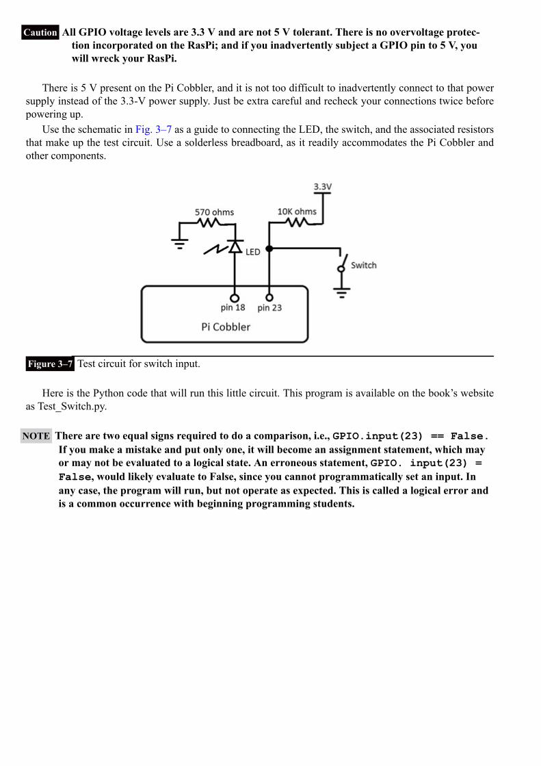
Caution All GPIO voltage levels are 3.3 V and are not 5 V tolerant. There is no overvoltage protec-tion incorporated on the RasPi; and if you inadvertently subject a GPIO pin to 5 V, youwill wreck your RasPi.
There is 5 V present on the Pi Cobbler, and it is not too difficult to inadvertently connect to that powersupply instead of the 3.3-V power supply. Just be extra careful and recheck your connections twice beforepowering up.
Use the schematic in Fig. 3–7 as a guide to connecting the LED, the switch, and the associated resistorsthat make up the test circuit. Use a solderless breadboard, as it readily accommodates the Pi Cobbler andother components.
Figure 3–7 Test circuit for switch input.
Here is the Python code that will run this little circuit. This program is available on the book’s websiteas Test_Switch.py.
NOTE There are two equal signs required to do a comparison, i.e., GPIO.input(23) == False.If you make a mistake and put only one, it will become an assignment statement, which mayor may not be evaluated to a logical state. An erroneous statement, GPIO. input(23) =False, would likely evaluate to False, since you cannot programmatically set an input. Inany case, the program will run, but not operate as expected. This is called a logical error andis a common occurrence with beginning programming students.

Test_Switch.py
I have used an if/else conditional statement in this program that checks if pin 23 is LOW or False,and if so, will set pin 18 to GPIO.HIGH. Otherwise, the conditional statement will go directly to the elseportion where pin 18 is set to GPIO.LOW.
Run the program and observe that each time you press the switch the LED light turns on and continuesto stay lit as long as the switch is pressed. Figure 3–8 shows the actual circuit on the breadboard with theRasPi connected with the flat ribbon cable to the Pi Cobbler.
Figure 3–8 Actual switch test setup.
Thinking in RasPi TimeYou must always think about the operational speed of the RasPi when creating a new program. The whileloop in this program repeats over a million times a second, meaning that all the commands in the loopare constantly being repeated. That’s the reason why I used an if/else conditional test statement to re-peatedly set the pin value HIGH so that it matches the duration of the key press. If I had neglected to add theelse portion, the first time the button was pressed, it would have lit the LED, but it would have remainedon. Try deleting the else portion to confirm this behavior. But why does it stay on?
The answer is simple: without the else portion, there is no command to turn it off. The pin becomeslatched so that it remains in the last state it was commanded to be in. That’s what I mean by thinking inRasPi time. I have found that it is possible for new (and sometimes, not-so-new) microprocessor program-mers to become very confused regarding this real-time aspect of programming. Controlling actual hardware

can be a challenge. I will attempt to point out these challenging program areas in the book projects to helpavoid confusion on your part.
MP3 Project RequirementsThe first step in any project is to specify the requirements that must be met to satisfy the project user. In thiscase, the project requirements are rather simple. They are listed below:
Use the mpg123 app as the MP3 playerPlay selected MP3 files (tracks) stored in a preset directoryUse the computer monitor to display file (track) dataUse the 3.5-mm analog audio jack for outputUse the keyboard to enter commands to control the mpg123 app while it is playing a songUse one of three push buttons to play a preselected song
It is a straightforward process to build this project, as most of the component parts and software havealready been discussed.
Writing the ProgramThe key issue is to start the mpg123 app from a Python program with all the needed arguments. Fortunately,Python provides a function named system() that allows us to do this quite easily. And, it is part of the OSpackage. The following Python program I created is named MP3_Player. py, and it is available for down-load from the book’s website.

MP3_Player.py
MP3 Player Schematic
All the pin and switch connections are shown in Fig. 3–9. You can simply add on the two additional push-button switches and resistors to the existing circuit that was built according to Fig. 3–7. You can also leavethe LED connected, if you so desire, as it will not be incorporated into this circuit.
Figure 3–9 MP3 player circuit.
Figure 3–10 shows the actual circuit on the breadboard with the RasPi connected via the flat ribboncable to the Pi Cobbler and the Veho360 connected to the analog output jack. The three push buttons thatselect one of three MP3 songs are placed on the right side of the solderless breadboard.
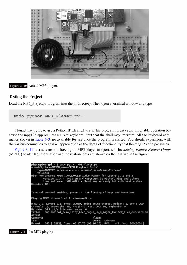
Figure 3–10 Actual MP3 player.
Testing the ProjectLoad the MP3_Player.py program into the pi directory. Then open a terminal window and type:
I found that trying to use a Python IDLE shell to run this program might cause unreliable operation be-cause the mpg123 app requires a direct keyboard input that the shell may interrupt. All the keyboard com-mands shown in Table 3–3 are available for use once the program is started. You should experiment withthe various commands to gain an appreciation of the depth of functionality that the mpg123 app possesses.
Figure 3–11 is a screenshot showing an MP3 player in operation. Its Moving Picture Experts Group(MPEG) header tag information and the runtime data are shown on the last line in the figure.
Figure 3–11 An MP3 playing.

Project ExpansionI have shown you a basic MP3 player that can be expanded in a variety of ways to meet future requirements.The display could be changed from a standard monitor to a multiple line serial liquid crystal display (LCD).For now, it is sufficient to focus on the simpler aspects of using the RasPi for project control.
Another aspect that you might have wondered about is the use of a separate push button dedicated to aspecific function, such as skip to the next track. Right now, you simply press the f key to do this. Incorpor-ating a unique button capability entails a lot of software rework because the mpg123 app expects controlkey input from what is logically known as the stdin or standard input device, i.e., the keyboard. Changingor paralleling the input device is not a trivial change, so I felt it was not suitable to include it in a beginningproject book.
Adding MP3 songs to be played is rather easy; as all you need to do is copy them into the default dir-ectory using the RasPi’s USB port. The program does have to be changed to reflect the new song names.However, the program can be modified to list all the MP3 songs in the directory so that you can select theones to be played, which is the essence of a play list.
Of course, you can connect a battery to power the RasPi that will make it completely portable, assumingyou are using an LCD-type display for user interaction.
SummaryI started this chapter with a discussion of the Pi Cobbler prototyping aide, which is an invaluable tool thatallows us to experiment with most of the GPIO pins that are available on the RasPi.
The Linux ALSA system discussion showed you how sound is handled by the RasPi OS. You must in-stall ALSA in order to use the mpg123 app that forms the basis for the MP3 player project. I also introducedyou to the principal audio file formats, including the MP3 format that is used to encode the music played inthe project. There was also a brief detour to discuss the RasPi’s audio frequency response using a pink-noisestimulus.
I then showed you how to use push-button switches to signal the RasPi, using GPIO pins as inputs.These switches were also used as part of the MP3 player project.
We went through a thorough discussion of the mpg123 MP3 app including a detailed list of all the con-trols available for use with this versatile app.
I finished with a brief discussion on how to expand the MP3 player so that it might more readily re-semble a modern portable player.

CHAPTER 4
Camera Controller
In this chapter, I will show you how to build a camera controller by using the RasPi with several auxiliary modulesthat will act as trigger sources. The controller will allow you to trigger a digital camera and/or an electronic flash ifthey are inherently capable of being remotely controlled. It will also enable you to take some very interesting picturesincluding stop-action photos.
The following three figures illustrate one simple experiment that demonstrates the controller’s stop-action effect. Imade a flag object out of black and white duct tape onto which I printed the numbers 1 and 2. I attached this “flag” toa nail that I inserted into a portable drill chuck. Figure 1 shows the drill chuck with the flag at rest.
Figure 4–1 Flag at rest.
Next, I started the drill and had it rotating at approximately 500 revolutions per minute (r/min). Figure 4–2 is a nor-mal photograph taken with my usual studio lights and without an electronic flash. This figure mimics what the humaneye perceives in that both numbers are visible because I used a slow shutter speed.
Figure 4–2 Flag rotating at 500 r/min.

Figure 4–3 is a picture taken with the electronic flash and a slow shutter speed in a darkened room. Youcan clearly see the number 2 visible and not blurred, even though it was rotating at 500 r/min or almost 10times per second.
Figure 4–3 Flag captured in a stop-action photo.
The controller will assist you in making similar stop-action pictures as well as many other effects thatyou may want to accomplish.
Project RequirementsI will start this project by listing the requirements that the controller system should meet. These have beensimplified to make the controller compatible with a wide variety of cameras and electronic flash units. Inorder to take full advantage of all the system functions, you will need a camera that is capable of being re-motely triggered. The controller system requirements are shown in Table 4–1.
Table 4–1 Camera Controller Requirements
Figure 4–4 is a high-level graphical diagram showing the module interconnections associated with eachmode listed in Table 4–1.
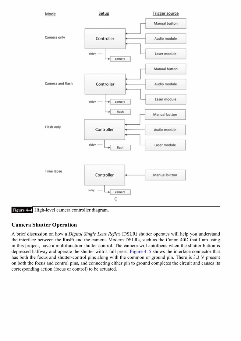
Figure 4–4 High-level camera controller diagram.
Camera Shutter OperationA brief discussion on how a Digital Single Lens Reflex (DSLR) shutter operates will help you understandthe interface between the RasPi and the camera. Modern DSLRs, such as the Canon 40D that I am usingin this project, have a multifunction shutter control. The camera will autofocus when the shutter button isdepressed halfway and operate the shutter with a full press. Figure 4–5 shows the interface connector thathas both the focus and shutter-control pins along with the common or ground pin. There is 3.3 V presenton both the focus and control pins, and connecting either pin to ground completes the circuit and causes itscorresponding action (focus or control) to be actuated.

Figure 4–5 Canon 40D shutter-control connector.
A special plug has to be used with this connector. I cannibalized a commercial, inexpensive, remoteshutter control in order to have a plug for this project. Figure 4–6 shows this plug with a molded cable.
Figure 4–6 Canon shutter-control plug and cable.
You can go to the website www.doc-diy.net/photo/remote_pinout/to look up your camera’s shutter-con-trol pin layout and matching connector. Some of the newest DSLRs are using a standard 3.5-mm stereo jackthat will make the interface connection much easier.
Do not despair if you do not have a camera capable of being remotely controlled. Simply use the soundor light-activated functions to trigger an electronic flash with your point-and-shoot camera set to a long ex-posure in a darkened room. The flash will illuminate the subject sufficiently to enable you to do stop-actionphotography. You will have to experiment with different exposure times to get the desired result, but you dohave the basic equipment to be successful.
DSLR owners will learn how to activate the focus and shutter controls in the optoisolator section afterreading the electronic flash discussions, which are next.
Electronic FlashThe electronic flash, or strobe, is the unit that produces a very bright light for a very brief instant in time.It is used to sufficiently illuminate a photographic subject where ambient light is too low in intensity or not

suitable for the subject. The electronic flash replaced the one-time-use flash bulb many years ago and isnow almost universally used in modern photography. Most digital cameras, from one-steps to DSLRs, havea built-in flash unit that automatically activates based upon the lighting conditions that the camera sensordetects. While this arrangement may suit most users, for this project, we cannot make use of the built-inunit but instead must rely on an external electronic flash that can be remotely triggered. Figure 4–7 showsthe Canon 420EX electronic flash that I will use in this project. It is several years old and has been replacedby the model 430EX. For our purposes, however, the differences between the models are not significant.
Figure 4–7 Canon model 420EX electronic flash.
The 420EX is designed to mount into the camera’s hot-shoe connection that provides the shutter activ-ation as well as a series of data interconnections. The data flow between the flash and the camera is notrelevant to the project, as the flash will not be mounted on the hot shoe. However, it is important to pointout the control connections that will be used to trigger the flash. These are detailed in Fig. 4–8.

Figure 4–8 Flash hot-shoe connections.
The flash will fire when the shutter-control pin is connected to the ground pin.
NOTE I used the descriptor, shutter control, to emphasize that the flash is fired only when the camerashutter operates. This pin obviously triggers the flash itself.
The ground pin, in actuality, consists of two spring-loaded, cam-shaped pins located on either side of theinner slides for the hot shoe. These make contact with the camera’s metal hot shoe. There are five spring-loaded pins shown on the bottom of the hot shoe. As mentioned earlier, we are only concerned with thecenter pin. The other four pins visible to the left of the center pin are data connections that are not usedin this project. I also used an inexpensive, commercially available hot-shoe adapter to bring out both theshutter-control and the ground connections. This adapter is shown in Fig. 4–9.
Figure 4–9 Hot-shoe adapter.
The adapter brings out the connections to a 3.5-mm plug that can be inserted into a standard mono jack.The adapter also incorporates a standard tripod mount, as shown in the figure inset. This makes it simple tomount the flash in any position as needed.

Electronic Flash Control VoltagesYou may have noticed that I put the 4.5-V control voltage in the Fig. 4–8 pin description. This is a typicalvoltage found on Canon electronic flash units, and it is quite compatible with this project’s interface cir-cuits. However, older electronic flash units may have significantly higher voltages present on the controlpin. These may range up to several hundred volts.
CAUTION Connecting an electronic flash with more than 24 V on the trigger contact to the projectinterface circuit will destroy the interface and may cause further damage to the RasPi.
Modern electronic flash units are expected to conform to ISO Standard 10330:2002 entitled “Photo-graphy—Synchronizers, ignition circuits and connectors for cameras and photoflash units—Electrical char-acteristics and test methods.” One portion of the standard requires that trigger voltages not exceed 24 Vmax. Canon has designed their units to operate at less than 6 V, and Nikon at less than 12 V. Older unitswere not designed to the standard and could conceivably have hundreds of volts exposed that would notonly destroy the interface but also present a personal shock hazard. To check flash voltages for your elec-tronic flash, go to the following excellent website: www.botzilla.com/photo/strobeVolts.html.
I do discuss a possible solution for using an older flash unit in the next section on the optoisolator in-terfaces. However, my earnest suggestion would be: Do not use an old flash, but instead invest in a modernunit. Many of these are available at quite reasonable prices.
Optoisolator InterfacesAn optoisolator combines a light source with a photosensitive transistor to create a photonic coupler. Thistype of isolator achieves electrical isolation between two electrical circuits that may have a significantvoltage difference present. Figure 4–10 shows a physical schematic for the NTE3041 optoisolater that isused in this project. It is in a six-pin dual in-line package (DIP) form with a gallium-arsenide infrared LEDas a light source and a silicon NPN phototransistor as the light receiver.
Figure 4–10 NTE3041 optoisolator.
Although it might appear that an optoisolator could pass analog or continuous signals, it is only suitablefor digital or on/off signals. That is due to the on/off functional nature of the LED used as the light source.NTE3041s are used as input and output isolators in this project. Figure 4–11 shows a very simple circuitthat is used to enable the NTE3041 to isolate one of the RasPi GPIO pins. All that is needed is a current-limiting resistor in series with the GPIO pin. The resistor value was set at 220Ω to provide a 10-mA drivecurrent to the LED in the optoisolator. This current level is suitable for both the RasPi and the optoisolator.There is also a 3-V Zener diode connected in series with the photo transistor’s collector, which affords a bitof protection in case of excessive voltages that might be present in the output circuit.

Figure 4–11 RasPi to optoisolator circuit.
CAUTION The NTE3041 is rated for a maximum of 30-V collector-to-emitter voltage (VCEO). Anyvoltage that exceeds that maximum rating will likely damage the optoisolator; however,the RasPi will still be protected.
I have used the NTE3041 optoisolators to connect the RasPi GPIO pins to the shutter (full press), focus(half press), and electronic-flash control pins. The sound and light modules do not require isolation, as theyalready use isolated relay contacts.
High-Voltage Optoisolator CircuitFigure 4–12 shows a circuit that can be used if you need to control an electronic flash that has high voltagepresent on the control pins. This circuit uses an optotriac (triode for alternating current) isolator in lieu ofthe NTE3041 optoisolator. The optotriac, in turn, turns on a silicon-controlled rectifier (SCR) that fires theflash unit. The SCR recommended is rated up to 400 V. I strongly recommend you do not use a flash unitwith more than that voltage.
Figure 4–12 High-voltage optoisolator circuit.
Connect the RasPi GPIO pins to pins 1 and 2 of the optotriac in the same manner as shown in theNTE3041 connections of Figure 4–11. Be sure to include the 220 Ω current limiting resistor.
Information about the suggested parts for the high-voltage optoisolator circuit is provided in Table 4.2.

Table 4–2 High-Voltage Optotriac Parts List
Sound and Laser ModulesAn important part of this project is to have the capability of triggering the camera and flash by using soundand light events. This means we need sensors to detect the sound and light as well as the associated circuitryto generate a signal when the preset thresholds are exceeded. These requirements raise an issue that oftencomes up in project planning: whether to build or buy. In this case, I decided to incorporate two inexpensivekits for sound and light detection. My decision was based on an estimate of how long it would take to buildand test two prototypes versus buying and building two kits and making any appropriate modifications tosuit this project. Listed here are the kits I used:
Global Specialties Model GSK-409Audio Control Switch kit $9.95
Ramsey Electronics Model LTS1Laser Trip Sensor kit $19.95
It turned out that neither kit required any interface modifications for use in the project, since both hadoutput relays that could directly connect with the RasPi GPIO pins without the need for optoisolators.
Audio ModuleAn assembled audio module is shown in Fig. 4–13. You will notice that I connected the microphone tothe main board with a foot-long twisted-wire pair, so that I would be able to position it for optimal soundpickup. The microphone is normally soldered directly to the main board, which would have made it awk-ward to position the board with the 9-V battery attached in order to best detect the trigger sound.
Figure 4–13 Model GSK-409 audio control switch.
This board does feature a flip-flop operation where the output relay is latched after a sound event. Thismeans that relay contacts will close and remain closed after the first sound event. The next sound event will

open the relay contacts, and they will stay that way until the next event, ad infinitum. This is really not alimiting feature for the project, since you would probably have planned to manually reset the module beforeany event using sound as a trigger.
Notice the sensitivity trim pot that I have pointed out in Fig. 4–13. I found that I had to adjust the potalmost fully clockwise, in order to have a reasonable opportunity to detect low-to-moderate volume soundevents.
This module is easily connected to the Pi Cobbler prototype board using the schematic shown in Fig.4–14.
Figure 4–14 Sound module to Pi Cobbler interface schematic.
Point 1 shown in Figs. 4–13 and 4-14 is connected to the Pi Cobbler ground pin. Point 2 also shown inFigs. 4–13 and 4-14 is connected to GPIO pin 24 on the Pi Cobbler. There is also a 10-kΩ pull up resistortied to the GPIO pin. The RasPi control program will be written to detect the high-to-low transition on theselected GPIO pin.
Laser ModuleAn assembled laser-light module is shown in Fig. 4–15. There are two assemblies, not counting the 12-Vpower supply, that make up this sensor module. The first is the laser pointer that acts as the light source, andthe second is the light sensor that consists of a phototransistor with some analog signal processing circuitry.The laser pointer is a very common low-power device that is typically battery powered. In this case, it ispowered by 5 V supplied by the detector board. The power is delivered through a pair of small alligatorclips, one of which is visible in the Fig. 4–15.

Figure 4–15 Model LTS1 laser trip sensor.
The light detector component is a phototransistor that is also pointed out in the figure. It looks like anormal LED but is a transistor with only the collector and emitter leads externally connected. It will con-duct when the laser light strikes the base-emitter region; however, it seems insensitive to normal ambientlight. I have not tried it in strong direct sunlight where I suspect it might conduct. I also purposely left offan ambient light shield to show you the transistor. When put in place, the light shield will help with falsetriggers.
The relay contacts in this module are normally closed when light is not being detected and will openwhen the laser light strikes the phototransistor. This means that the RasPi program will need to be changedto detect a low-to-high transition provided the same interface is used, as is shown in Fig. 4–14. That’s whatis so nice about using the RasPi and Python: changes can easily be made in software to accommodate hard-ware issues.
Interface ConnectionsAll of the interface connections are shown in Figure 4–16. There are three input push buttons to manuallytrigger focus, shutter, and flash; three output optoisolator connections that allow the RasPi to trigger focus,shutter, and flash; and finally, there are two inputs from the sound and light modules. This might seem to bea lot, but the circuits are quite simple and repetitive.

Figure 4–16 All of the interface connections.
The hardest part was to interconnect the modules, camera, and flash to the breadboards. I finally determ-ined that using audio cables terminating with 3.5-mm jacks was the easiest way for me to do it. You can usewhatever you have available, such as a twisted pair, because the connections are DC based with practicallyno speed or bandwidth issues. The complete prototype is shown in Fig. 4–17. It is a bit of a “rat’s nest” asfar as the wiring goes, but it is totally functional and allowed me to rapidly progress with the project.

Figure 4–17 Complete camera controller prototype.
CAUTION Ensure that you use the appropriate ground connections, as shown in Fig. 4–16. For in-stance, the camera ground is separate and distinct from the RasPi ground. No harm wouldresult if you inadvertently connected the optoisolator grounds to the breadboard ground,but the isolators would simply not function properly.
Table 4–3 lists all the GPIO pins used in the interface with the associated functions tied to those pins.
Table 4–3 GPIO Pin Function Interface List
NOTE Starting with revision 2 for Models A and B, pin 21 has been redesignated pin 27. It remainspin 21 for revision 1 models A and B. The Pi Cobbler, Pi Plate, and likely other prototypetools have pin 21 shown. I would suggest putting a piece of tape over the 21 and relabeling it27 if you are using revision 2 models. The GPIO library recognizes pin 27 without any issues.
Testing the Interface ConnectionsYou should test all the connections to ensure that everything is wired correctly. The only item you will needis a standard volt-ohm meter (VOM) to run through all the tests. You will not require any software to be

running on the RasPi for these tests although the RasPi must be turned on in order to provide power to thePi Cobbler and breadboards.
First check each of the push buttons. There should be 3.3 V present on pins 18, 22, and 23. The voltageshould drop to 0 V when one of the buttons connected to the pin under test is pushed.
Next, check the camera optoisolators. First ensure that the wires going from pins 4, 17, and 21 are tem-porarily disconnected. Then plug the shutter-control cable into the camera and then turn on the camera.Using a jumper wire, connect the 3.3-V power supply on the breadboard to the 220-Ω resistor that connectsto pin 1 of the optoisolator.
CAUTION Do not touch pin 1 on the optoisolator with the 3.3-V jumper wire. You must go through thecurrent-limiting resistor or else the LED in the optoisolator could burn out from excessive cur-rent.
You should observe either the camera auto-focusing or the shutter operating, depending upon which op-toisolator you are testing.
The electronic flash should be tested next. Plug the remote hot shoe into the flash and ensure that it isalso connected to its controlling optoisolator. Turn on the flash and then touch the 3.3-V jumper wire to the220-Ω, current-limiting resistor that is connected to the optoisolator. The flash should operate.
Remember to reconnect all the wires between the optoisolators and their respective GPIO pins, as shownin Fig. 4–16.
The sound and light modules are tested last. Connect the modules to the breadboard and power them on.You do not have to disconnect the wires going between the GPIO pins and the module interfaces for thesetests. The sound module connection will be either on or off, depending upon the state of the latched relay.Using the VOM, check to see that pin 24 switches between 3.3 V (on) and 0 V (off). This is a valid test forthe sound module because it operates in the same manner as the push-button interface.
The laser-light module is checked in a similar fashion at pin 25. However, as mentioned above, themodule-relay contacts are closed when light is not striking the phototransistor. This means that pin 25should have 0 V when no light is on the sensor and 3.3 V when light strikes the sensor.
If you have any problems, recheck all the wiring, since it is very easy to misplace a jumper wire on thesolderless breadboards. Also, ensure that you have all the appropriate grounds connected, as shown in thefigures.
Initial Test Program
The following program tests the camera focus and shutter controls as well as the electronic flash byusing the push buttons. It is named CameraControl .py and may be downloaded from the book’s website,www.mhprofessional.com/raspi.

CameraControl.py
I recommend running this program directly from a terminal window as follows:
Press each of the push buttons and confirm that the appropriate action occurs. When you are finished,type ^c to exit the program.
You should note that I reset the controlling GPIO pin after making it a HIGH value. This ensures that itis in the proper state for the next operation.
Sound Module Test Program
The following program tests the sound module to check that the focus, shutter, and flash can be triggeredwhen the sound module detects a sound event. The first portion of this program is identical to the previousprogram. This program interacts with you through the screen by prompting a number representing the testto be performed. The prompts are shown on the screen and are also shown here:
1—Test the shutter only.
2—Test the flash only.

3—Test the shutter and flash together.
0—Exit the program.
The program is coded as a series of loops that wait for a trigger event from the sound module beforeactivating the requested function(s). This program is available on the book’s website as SoundModTest.py.
Just be aware that you must reset the sound module after it has been triggered because of the latchedoperation. It is a simple matter of a one-hand clap to trigger it so that the module LED turns off and themodule is in a proper ready state.
Light Module Test Program
The program to test the light module is almost identical to the sound-module test program.. The onlychanges are in the three GPIO.input conditional if statements that need to be changed fromif(GPIO.input(24) == False) to if(GPIO.input(25) == True). These changes arerequired because the light module is connected to pin 25 in lieu of pin 24 and its relay contacts are normallyclosed instead of normally open, as I mentioned earlier in this chapter.
To save book space, I will not repeat the code listing, as the changes are minor. This program,SoundModTest.py, is available from the book’s website and is named LightModTest.py.

SoundModTest.py
To test this module you will need to aim the laser at the phototransistor, which should turn off the LEDon the detector board. Next, block the laser light beam with an opaque item, which should trigger the lightmodule and initiate the requested function. There is no need to reset the light module, since it is not latched.
Time-Lapse FunctionThe last camera controller function to test is time-lapse photography. This is where you set a maximum timeto take photos at a preset interval. I created the program using only the shutter function, as I believe that willbe its primary use. Normally, time-lapse photography is done outdoors without the need of a flash. Also, itdoesn’t make sense to incorporate the sound or light triggers for this function. The program is quite simpli-fied as compared to the previous programs and is listed below. It is also available from the book’s websiteas TimeLapse.py.

NOTE The interval should be entered as a decimal if you need fractions of a minute, i.e., an intervalof six seconds would be entered as .1.
Operational Code
The four test programs, CameraControl.py, SoundModTest.py, LightModTest.py and TimeLapse.py shouldserve as templates to create whatever style operational program meets your needs. It is impossible for meto create the wide variety of control programs that are possible because there are so many different envir-onments that would need to be accommodated. It is easy to add additional functionality to any of these pro-grams by simply adding the desired input and/or output triggers. For instance, if you needed a flash for thetime-lapse function, you would add GPIO.output(27, GPIO.HIGH) after the GPIO.output(17,GPIO.HIGH) statement and do a similar add after the GPIO reset. Also note that I used 27 in lieu of 21due to the rev 2 board I used.
TimeLapse.py
SummaryThis chapter started with a project-requirements list that also served as a list of goals that you needed toaccomplish. Requirements drive all projects, and you should spend a great deal of time analyzing and de-termining what the essential requirements or needs are before proceeding to any design work.
I next discussed how a DSLR camera with an electronic flash could be remotely controlled. I electedto use optoisolators where appropriate to lessen any chance of damaging voltages being introduced into theRasPi interface circuits. I also mentioned that you could use a non-DSLR camera, set to a long exposure,with the electronic-flash function to capture stop-action events.
In a detailed discussion regarding optoisolators, I explained that they are very handy for completing in-terface circuits that incorporate a high level of voltage isolation. I also provided a triggering circuit for thosebrave souls with a high voltage electronic flash.
I went through my build-versus-buy decision regarding the sound and light modules. I was very pleasedto find that I had made the right decision, as I had no trouble incorporating these kits into the project. Youwill find that your time is very valuable and finding ways to shorten a project, such as incorporating prebuiltcomponents and/or kits, can be a valuable tool for maximizing your productivity.
I next went through a step-by-step testing procedure to ensure that the interface circuits were workingas designed. There was no need to run any programs on the RasPi at this stage. It is always a prudent ideato carefully check and test all interface circuits before running any programs. Testing in this fashion allowsyou to determine that any later functional problems are probably due to program glitches, not the interfacecircuits.

I then introduced a series of four test programs to methodically check that all planned project require-ments were met and that all the components functioned as desired. These four programs will serve as goodtemplates to allow you to create your own custom programs. You can design them to best suit your needs,or you can simply use them as they are.

CHAPTER 5
GPS
IntroductionIn this chapter, I will first discuss what constitutes the Global Positioning System (GPS), a satellite-based navigationsystem, and the advantages and limitations that are involved with using it. I will next explain how a serial communic-ation link may be set up and run between the RasPi and a laptop computer.
Finally, I will show you how to connect a very capable GPS receiver to the RasPi and subsequently use a series ofapplications to decode and display target, position, and velocity (TPV) information on the RasPi screen.
Brief GPS HistoryThe GPS system was initially deployed in the early 1970s by the U.S. Department of Defense (DoD) to providemilitary users with precise location and time synchronization services. Civilian users could also access the system;however, the services offered to the public were purposely degraded to avoid national security risks. The DoD wasconcerned that the system might help potential enemies in their activities. This intentional degradation was lifted byorder of President Reagan in 1983 to allow civilian use of full and more accurate GPS services. In 2000, an even high-er level of accuracy without any degradation was implemented for all users.
The current GPS system has 32 satellites in high orbits over the earth. A representative diagram of the satellite“constellation” is shown in Fig. 5–1. The satellite orbits have been carefully designed to allow for a minimum of sixsatellites to be in the instantaneous field of view of a GPS user located anywhere on the surface of the earth. A minim-um of four satellites must be viewed in order to obtain a location fix, as you will learn in “The Basics of How a GPSFunctions” section.
Figure 5–1 Diagram of the GPS satellite “constellation.”
Several other GPS systems are also deployed:

GLONASS—The Russian GPSGalileo—The European GPSCompass—The Chinese GPSIRNSS—The Indian Regional Navigation Satellite System”
I will be using the American GPS system, as vendors have made many inexpensive receivers availableto purchase. All receivers function in essentially the same way and conform to the National Marine Elec-tronics Association (NMEA) standard discussed in the “NMEA Protocol” section.
The Basics of How GPS FunctionsI made up an analogous fictional position-location system to help explain how the GPS system functions.First, imagine a two-mile by two-mile land area where this system is set up. The land terrain contains gentlyrolling hills, each no more than 30 feet in height. The subject, using a “special” GPS receiver, may be loc-ated anywhere within this area. Also located in this area are six 100-foot towers, each containing a beacon.The beacon atop each tower is configured to briefly flash a light and emit a loud sound burst simultan-eously. Each beacon also emits light and sound pulses once a minute but at a specific time within the minute.Beacon one (B1) emits at the start of the minute, beacon two (B2) at 10 seconds past the start of the minute,beacon three (B3) at 10 seconds later, and so on for the remaining beacons.
It is also critical that the GPS receiver have an open line of sight to each beacon and that the positionof each beacon be recorded in an embedded database that is also constantly available to the receiver. Thepositions of beacons B1 through B3 are recorded as x and y coordinates in terms of miles from the originthat is shown in the upper left hand corner of Fig. 5–2.
Figure 5–2 Beacon test area.
The actual position determination happens in the following manner:
At the start of the minute, B1 flashes, and the receiver starts a timer that stops when the sound pulse isreceived. Since the light flash is essentially instantaneous, the time interval is proportional to the dis-tance from the beacon. Since sound travels at a nominal 1100 feet per second (ft/s) in air, a 5-seconddelay would represent a 5500-foot distance. The receiver must then be located somewhere on a

5500-foot radius sphere that is centered on beacon B1. Figure 5–3 illustrates this abstraction as a graph-ical representation taken from a Mathworks Matlab application.
Figure 5–3 One sphere.
B2 flashes next. Suppose that it takes 4 seconds for the B2 sound pulse to reach the GPS receiver. Thisdelay represents a 4400-foot sphere centered on B2. The B1 and B2 spheres are shown intersecting inFig. 5–4. The heavily dashed line represents a portion of the circle that is the intersection of these twospheres. The receiver must lie somewhere on this circle,which appears to be a straight line when ob-served in a planar or perpendicular view. However, there is some uncertainty about where the receiver islocated on the circle. Thus, another beacon is still needed to resolve the uncertainty.

Figure 5–4 Two spheres.
B3 flashes next. Suppose that it takes 3 seconds for the B3 sound pulse to reach the GPS receiver. Thisdelay represents a 3300-foot sphere centered on B3. The B1, B2, and B3 spheres are shown intersectingin Fig. 5–5. The receiver must be located at the star shown in the figure. In reality, it could be at either ahigh or low point, since the third sphere intersects the two other spheres at two points. The receiver pos-ition has now been fixed with regard to x and y coordinates but not the third or z coordinate. Guesswhat? You now need a fourth beacon to resolve whether the receiver is at the high or low point. I am notgoing to go through the whole process again because I think you have figured it out by now.

Figure 5–5 Three spheres.
Figure 5–5 shows a plane view of all three spheres with the GPS receiver position shown. You can thinkof it as a horizontal slice taken at z = 0 in Fig. 5–6.
Figure 5–6 Plane view.
In summary, it takes a minimum of three beacons to determine the x and y coordinates, and a fourthbeacon to fix the z coordinate. Now translate the beacons to satellites and the x, y, and z coordinates to latit-ude, longitude, and altitude, and you have the basics of the real GPS system.
The satellites transmit digital microwave radio-frequency (RF) signals that contain both identification(ID) and timing components that a real GPS receiver will use to calculate its position and altitude. Thecounterpart to the embedded database mentioned in my fictional example is called an ephemeris or celesti-al almanac, and it contains all the data necessary for the receiver to calculate a particular satellite’s orbitalposition. As mentioned in the history section earlier, all GPS satellites are in high earth orbits and are con-stantly changing position. Because of this situation, the receiver must use a dynamic means for determining

its position fix, which, in turn, is provided by the ephemeris. This is one reason why it may take a while fora real GPS receiver to establish a lock, as it must go through a large amount of data calculations to determ-ine the actual satellite positions within its field of view.
In my fictional example, the radii of the “location spheres” are determined by the receiver using ex-tremely precise timing signals that are contained in the satellite transmissions. Each satellite contains anatomic clock to generate these clock signals. All satellite clocks are constantly synchronized and updatedfrom earth-based ground stations. These constant updates are needed to maintain GPS accuracy, whichwould naturally degrade because of two relativistic effects. The best way to describe the first effect is toretell the paradox of the space-travelling twin.
Imagine a set of twins (male, female—it doesn’t matter), one of whom is slated to take a trip on a faststarship to our closest neighboring star, Alpha Centauri. This round trip will take about ten years travelingnearly at the speed of light. The remaining twin will stay on earth awaiting the return of his/her sibling. Thetwin in the starship will accelerate very close to light speed and will patiently wait the ten years it will taketo make the round trip according to the clock in the ship. Now, according to Albert Einstein, if the travelingtwin could view a clock on earth he/she would observe time going by at a much quicker rate then it wasin the starship. This effect is part of the theory of special relativity and, more specifically, is called timedilation. If the twin on Earth could see the clock in the starship, he/she would notice it was turning muchmore slowly than the earthbound clock. Imagine what happens when the traveling twin returns and findsthat he/she is only ten years older but the earthbound twin is 50 years older because of time dilation. Thespace-traveling twin will have time traveled a net 40 years into Earth’s future by taking the ten-year spacetrip!
The second effect is more complex than time dilation, and I will simply state what it is. According toEinstein’s theory of general relativity, objects located close to massive objects, such as the Earth, will havetheir clocks moving slower as compared to objects that are further away from the massive objects. This ef-fect is due to the curvature of the space-time continuum and has been predicted and experimentally verifiedby the general relativity theory.
Now back to the GPS satellites that are orbiting at 14,000 kilometers per hour (km/h), while the earth isrotating at a placid 1,666 km/h. The relativistic time dilation due to the speed differences is approximately–7 microseconds per day (μs/day), while the difference due to space-time is +45 μs/day for a net satelliteclock gain of 38 μs/day. While this error is nearly infinitesimal on a short-term basis, it would be very no-ticeable over a 24-hour time period. The total daily accumulated error would amount to a position error of10 km or 6.2 miles (mi), essentially making GPS useless. That’s why the earth ground stations constantlyupdate and synchronize the GPS satellite atomic clocks.
NOTE The atomic clocks within the GPS satellites are deliberately slowed prior to launch in order tocounteract the relativistic effects described earlier. Ground updates are still needed to ensurethat the clocks are synchronized to the desired one-nanosecond accuracy.
The Ultimate GPS ReceiverI will be using the Ultimate GPS receiver breakout board available for about $40 from Adafruit Industries.This receiver is shown in Fig. 5–7.

Figure 5–7 Ultimate GPS receiver breakout board.
This receiver meets the following comprehensive technical specifications that make it ideal for this ap-plication:
Satellites: 22 tracking, 66 searchingPatch antenna size: 15 mm × 15 mm × 4 mmUpdate rate: 1 to 10 hertz (Hz)Position accuracy: 1.8 metersVelocity accuracy: 0.1 meter per second (m/s)Warm/cold start: 34 secondsAcquisition sensitivity: –145 dBmTracking sensitivity: –165 dBmMaximum altitude for PA6H: tested at 27,000 metersMaximum velocity: 515 m/sVIN range: 3.0–5.5 VMTK3339 operating current: 25 mA tracking, 20 mA current draw during navigationOutput: NMEA 0183, 9600 baud (Bd) defaultDGPS/WAAS/EGNOS supportedFCC E911 compliance and AGPS support (Offline mode: EPO valid up to 14 days)Up to 210 PRN channelsJammer detection and reductionMultipath detection and compensationCapability of an external antenna being attachedUART for data communications. (This last feature will be discussed further in the following section,“UART Communications.”)
I will neither need nor use many of these features, but they are listed here to give you an appreciation ofthe technical complexity and versatility of this particular GPS receiver.
There are several key specifications that are worth discussing a bit more. An acquisition sensitivity of–145 dBm means the receiver is extremely sensitive to picking up weak GPS signals. The –165 dBm track-ing sensitivity means the signal, once acquired, can lose up to 90 percent of its original strength, yet remainlocked in by the receiver.

Having an output operating at 9600 Bd and compliant with the National Marine Electronics Association(NMEA-0183) standard means the receiver generates standard GPS messages at a rate twice as fast as thatof comparable receivers.
The VIN range of 3- to 5.5-V matches very nicely with the RasPi 3.3-V operating voltage, thus elimin-ating the need for any buffer circuitry.
The 34-second start-up time is excellent and probably due in part to the extreme receiver sensitivity.
UART CommunicationsThe Universal Asynchronous Receiver/Transmitter (UART) was introduced in Chap. 1 as one of the severalserial data protocols/sub-systems that the RasPi incorporates into its design. In this section, I will explorehow to set up a terminal control session, also known as a console control session, by using the built-in serialUART protocol. A minimum of three GPIO pins are necessary to establish a console control session. Asshown in Fig. 5–8, these pins are part of the 26-pin GPIO header and have the function of transmit (TXD),receive (RXD), and ground or common (GND).
Figure 5–8 UART pins.
A simple serial communications link between a laptop computer and the RasPi will demonstrate howthis type of communication functions. A terminal program running on the laptop will handle that side of thelink, while the built-in, serial-protocol software will handle the RasPi side. An interconnecting cable willalso be needed along with a very useful software driver. The link is set up using a USB to serial TTL cablethat is connected to the GPIO header, as shown in Fig. 5–9.

Figure 5–9 USB to Serial TTL link cable.
The cable has four pin connectors that are color-coded and attached to the GPIO header as detailed inTable 5–1. This cable is available from Adafruit Industries as part number 954.
Table 5–1 GPIO Header to USB/TTL Cable Connections
CAUTION DO NOT CONNECT the red lead to the GPIO header if you are using the “regular” micro-USB power supply. This red lead is provided to allow you to power the RasPi from the hostcomputer’s USB port; however, you cannot simultaneously power the RasPi from themicro-USB power supply and the USB-port power supply, only one or the other. My re-commendation is: Do not use this 5-V power supply; just continue to use the regular powersupply.
There are many terminal programs available that will provide the laptop-side communications verynicely. Two recommendations are:
Tera Term—the Tera Term Project—http://ttssh2.sourceforge.jp/index.html.enZOC—http://www.emtec.com/zoc/terminal-emulator.html
You will need one more vital software piece to complete the communications link. This would bea USB driver that provides the logical connection between the RasPi UART/TTL pins and the laptop’sUSB port connection. The driver is available from the Prolific website at http://www.prolific.com.tw/US/ShowProduct.aspx?p_id=225&pcid=41, which takes you to the PL2303 Windows driver download page.The driver file name is PL2303_Prolific_DriverInstaller_v1.7.0.zip. This driver creates what is known as avirtual comm port that allows a USB port to emulate a standard RS-232 serial port. The comm port createdin my case was comm5; however, yours may vary depending upon your laptop’s configuration. In any case,use the new comm port in configuring the serial link, as I have shown in Fig. 5–10. In this screenshot, I wasusing the Tera Term program.

Figure 5–10 Terminal program port selection.
The port configuration settings are shown in Fig. 5–11. You click on Setup, then Serial Port to get to thisscreen, when using the Tera Term program.
Figure 5–11 Serial port configuration settings.
The key parameters to set, independent of the terminal program that you are using, are the following:
Baud rate—115,200Number of data bits—8Parity—NoneStop bits—1
You should see a screen similar to the screenshot in Fig. 5–12, if you have setup everything correctlyincluding the Prolific driver.

Figure 5–12 Sample screenshot from Tera Term program connected to RasPi.
Figure 5–13 shows another screenshot using the ZOC terminal control program connected to the RasPi.
Figure 5–13 Sample screenshot from the ZOC program connected to the RasPi.
In a later chapter, I will show you how to connect to the RasPi over a network by using another type ofterminal control program in lieu of using a direct serial cable. But for now, you have the background andfamiliarity to set up a serial link with a GPS receiver.
GPS Receiver UART Communication
The Ultimate GPS receiver uses a 9600-Bd UART to communicate with the controlling microprocessor inorder to both receive and transmit data back and forth. The UART interface pins available on the UltimateGPS receiver are shown in Fig. 5–14. There are only three pins that we need to use for data communication,as was discussed in the previous section.

Figure 5–14 Ultimate GPS data communication interface pins.
There is no need for a separate clock signal line, since the UART protocol is designed to be “self-clock-ing.”
Next, you need to make the connections between the Pi Cobbler UART pins and the GPS receiver pins,as shown in Fig. 5–15.
Figure 5–15 Pi Cobbler to GPS receiver connections.
CAUTION Ensure that the TX connector from the GPS receiver connects to the Pi Cobbler RX pin,and likewise, that the RX connector from the GPS receiver connects to the Pi Cobbler TXpin. Do not connect RX to RX or TX to TX even though that may seem like the logical ac-tion to take. You will not damage anything, but the data communications between the GPSreceiver and the RasPi cannot be established if you make those connections.

Initial GPS Receiver TestIt would be wise to check that the Ultimate GPS receiver is functioning as expected prior to running anycode on the RasPi. Ensure that you have a good line of sight with the open sky in order to receive the GPSsatellite signals. I used an external GPS antenna, since my test setup was indoors without any reliable satel-lite reception. The antenna was purchased from Adafruit Industries, part number 960, and is well worth themodest cost because erratic or unreliable satellite reception will quickly cause this project to fail. You willalso need an antenna adapter to connect the external antenna’s SMA connector to the μFL connector situatedon the Ultimate GPS receiver board. This adapter was also purchased from Adafruit, part number 851, andis shown in Fig. 5–15. A word of caution: Be very careful when pushing the μFL connector into the boardbecause the inner pin appears to be quite fragile and probably would be damaged if excessive pressure wereapplied.
The quickest and easiest approach for a data connection is to temporarily connect the laptop to the GPSreceiver with the USB/TTL cable using the connections shown in Fig. 5–16. You can parallel connect to theexisting TXD and GND on the solderless breadboard without a problem.
Figure 5–16 USB/TTL cable connection from GPS to laptop.
I used the Tera Term program with the baud rate set to 9600 to match the GPS receiver output. Figure5–17 is a screen capture of the GPS data stream showing that the GPS receiver was properly functioningand receiving good satellite signals.

Figure 5–17 Tera Term screen capture of GPS data stream.
The next step in confirming proper GPS operation is to disconnect the USB/TTL cable and load theRasPi with a terminal program to confirm that the RasPi can also receive the GPS data stream. I used avery nice serial terminal control program that runs in a graphical user interface (GUI) named CuteCom. Toinstall this program, type the following into a terminal window:
NOTE I had to type “sudo apt-get update” prior to entering the above command because the apt-getrepository didn’t initially find the CuteCom package.
Next, you must edit the file named inittab located in /etc directory in order for CuteCom to communicatewith the GPS receiver. Change the line below into a comment line.
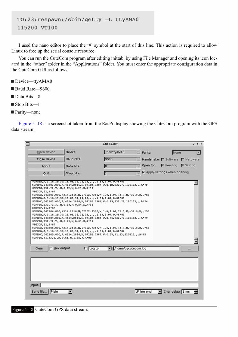
I used the nano editor to place the ‘#’ symbol at the start of this line. This action is required to allowLinux to free up the serial console resource.
You can run the CuteCom program after editing inittab, by using File Manager and opening its icon loc-ated in the “other” folder in the “Applications” folder. You must enter the appropriate configuration data inthe CuteCom GUI as follows:
Device—ttyAMA0Baud Rate—9600Data Bits—8Stop Bits—1Parity—none
Figure 5–18 is a screenshot taken from the RasPi display showing the CuteCom program with the GPSdata stream.
Figure 5–18 CuteCom GPS data stream.

Completing the steps just described confirms the proper operation of the Ultimate GPS receiver and theproper functioning of the data connection between the RasPi and the receiver.
You are almost ready to start using the GPS receiver, but first I need to discuss the NMEA protocol andthe messages that are being generated from the Ultimate GPS receiver.
NMEA ProtocolNMEA is the acronym for the National Marine Electronics Association, but nobody refers to it by its formalname. NMEA is the originator and continuing sponsor of the NMEA 0183 standard, which defines, amongother things, the electrical and physical standards to be used in GPS receivers. This standard specifies aseries of message types that receivers use to create messages that conform to the following rules, also knownas the Application Layer Protocol Rules:
The starting character in each message is the dollar sign.The next five characters are composed of the talker ID (first two characters) and the message type (lastthree characters).All data fields that follow are delimited by commas.Unavailable data is designated by only the delimiting comma.The asterisk character immediately follows the last data field, but only if a checksum is applied.The checksum is a two digit hexadecimal number that is calculated using a bitwise exclusive OR al-gorithm on all the data between the starting ‘$’ character and the ending ‘*’ character but includingthose characters.
There are a large variety of messages available in the NMEA standard; however, the following subset isapplicable to the GPS environment and is shown in Table 5–2. All GPS messages start with “GP.”
Table 5–2 NMEA GPS Message Types

Latitude and Longitude Formats
The two digits immediately to the left of the decimal point are whole minutes, to the right are decimals ofminutes. The remaining digits to the left of the whole minutes are whole degrees.
Examples:4224.50 is 42 degrees and 24.50 minutes or 24 minutes, 30 seconds. .50 of a minute is exactly 30seconds.7045.80 is 70 degrees and 45.80 minutes or 45 minutes, 48 seconds. .80 of a minute is exactly 48seconds.
Parsed GPS Message
The following is an example of a parsed GPGLL message that illustrates how to analyze an actual data mes-sage:
1. GP—GPS NMEA designator2. GLL—Lat/Lon message type3. 5133.80—Current latitude 51 degrees, 33 minutes, 48 seconds4. N—North/South5. 14240.25—Current longitude 142 degrees, 40 minutes, 15 seconds6. W—East/West7. *75—Checksum
All GPS applications use some type of parser application to analyze data messages and extract the re-quired information to meet system requirements. This will be discussed in the next section.
The gpsd AppsIt is time to install and run the RasPi GPS application now that the GPS receiver and serial data connectionhave been proved to work correctly. I will actually be using a suite of GPS tools or apps contained in apackage named gpsd. Enter the following command in a Linux terminal window to download and installthis suite:
gpsd is known as a daemon (pronounced daymon) and essentially is a program that runs in the LinuxOS background. The nice thing about daemons is that they go about their business without needing any at-tention once started. To start gpsd, type the following in a Linux terminal window:
All that’s happening here is that you are telling the daemon which serial connection is being used, inthis case, ttyAMA0.

Display GPS DataThe cgps app displays the GPS information, such as speed, position, altitude, etc. To see this information,type cgps in a Linux terminal window after starting the gpsd daemon.
You should see the screenshot shown in Fig. 5–19 appear on the RasPi screen.
Figure 5–19 A cgps screenshot.
The figure shows the parsed, or analyzed, GPS data that is streaming in real time from the Ultimate GPSreceiver. There is a lot of information displayed, including the following on the left-hand side:
Date—YYYY-MM-DDTime—UTC accurate to 1 millisecondLatitude—xx.xxxxxx N or SLongitude—xxx.xxxxxx E or WAltitude—Meters (above sea level)Speed—Kilometers/hour (km/h or kph)Heading—Degrees true (not magnetic)Climb rate—Meters/second (applicable to aviation)Status—Usually 3D but maybe 2D or no fixLongitude error—Usually several metersLatitude error—Usually several metersAltitude error—Meters (could be 10s of meters)Course error—Degrees (applicable to aviation)

Speed error—Usually a fraction of a km/h or kphTime offset—Difference between GPS and UTC clocks (usually ignored)Grid Square—The Maidenhead Locator System grid indicator
On the right-hand side is a real-time list of the GPS satellites in view. There were six satellites in Fig.5–19, three of which were used in computing the location fix. In all likelihood, the satellites not used hadinsufficient signal strength as indicated by a low signal to noise ratio (SNR).
The bottom of Fig. 5–19 shows a portion of the raw GPS data stream that gpsd uses to parse data forthe cgps application. The TPV tag seen repeatedly in the data stream stands for target, position, and velocityand is probably the most common tag in a GPS data stream.
There is also a graphical GPS display that can be run by typing xgps in a Linux terminal window. Figure5–20 is a RasPi screenshot showing this graphical display.
Figure 5–20 An xgps screenshot.
The top portion of the figure is the GPS constellation that is in a real-time sky view of the receiver. Thedata shown is almost identical to the satellite data shown on the right-hand side of Fig. 5–19. In a similarfashion, the data shown on the bottom of Fig. 5–20 is nearly identical to the left-hand side data shown in
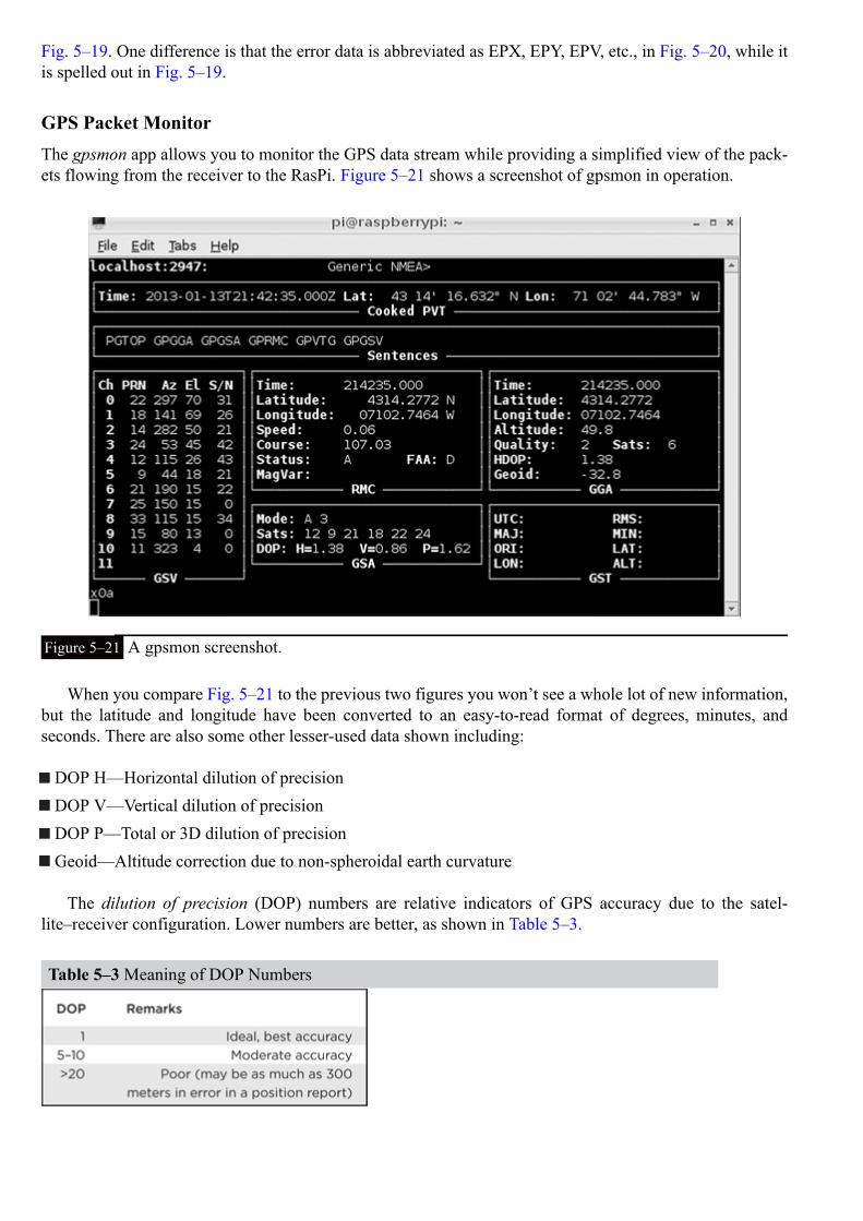
Fig. 5–19. One difference is that the error data is abbreviated as EPX, EPY, EPV, etc., in Fig. 5–20, while itis spelled out in Fig. 5–19.
GPS Packet MonitorThe gpsmon app allows you to monitor the GPS data stream while providing a simplified view of the pack-ets flowing from the receiver to the RasPi. Figure 5–21 shows a screenshot of gpsmon in operation.
Figure 5–21 A gpsmon screenshot.
When you compare Fig. 5–21 to the previous two figures you won’t see a whole lot of new information,but the latitude and longitude have been converted to an easy-to-read format of degrees, minutes, andseconds. There are also some other lesser-used data shown including:
DOP H—Horizontal dilution of precisionDOP V—Vertical dilution of precisionDOP P—Total or 3D dilution of precisionGeoid—Altitude correction due to non-spheroidal earth curvature
The dilution of precision (DOP) numbers are relative indicators of GPS accuracy due to the satel-lite–receiver configuration. Lower numbers are better, as shown in Table 5–3.
Table 5–3 Meaning of DOP Numbers

SummaryThe chapter began with a brief history of the GPS system followed by a tutorial example that explained thebasic underlying principles governing the system.
Next, I discussed the Ultimate GPS receiver, focusing on its excellent receiver characteristics as well asthe easy serial communication link.
I discussed how to setup and test a serial console link using a USB to serial TTL cable as well as serialterminal control programs for both a Windows laptop and the RasPi. The serial comm link between the GPSreceiver and the RasPi was setup, and a series of communication tests were demonstrated to verify the prop-er operation of all system components.
The NMEA 0183 protocol was thoroughly examined to illustrate the rich set of messages that are createdby the GPS receiver. This project uses only a small subset of the data but you should be aware of what ispotentially available. A parsed GPS message was also shown along with a brief explanation of how to in-terpret latitude and longitude data.
The remaining portion of the chapter concerned the gpsd suite of applications including cgps, xgps, andgpsmon. These apps provide an excellent set of tools to display and analyze the continuing stream of GPSdata produced by the Ultimate GPS receiver.

CHAPTER 6
Earthquake Detector
IntroductionI will show you how to build a sensitive earthquake detection system using the RasPi as a controller that both pro-cesses and displays the signals generated by the detector.
Let us begin with a discussion of seismology and earthquakes, focusing on their makeup and how they are meas-ured. Seismology is the term used to describe the study of earthquakes. This background section will help you under-stand the key concepts behind the detection-system design and what you should realistically expect from this fairlysimple system.
I have also included a section on the analog-to-digital conversion that is needed to allow the RasPi to link to theearthquake, or more generally termed, seismic detector.
Some sample plots are also shown to help you understand the system outputs and to show you how you might usethis system to detect imminent quakes, thereby providing you and your family with a bit more warning time in orderto allow you to avoid or minimize a bad situation.
Seismology and EarthquakesAn earthquake, or more simply a quake or tremor, generally refers to any large release of energy from within theEarth’s crust. There are a variety of sources that can cause this energy release, including a sudden displacement or shiftin the ground, often located well below the surface level. This energy is measured in a localized area by the Richtermagnitude scale, and globally, by the moment magnitude scale. The Richter scale is considered open-ended but gen-erally ranges between 2 and 9, with level 2 quakes not being felt and level 9 quakes creating catastrophic destruction.Figure 6–1 diagrams the Richter scale plotted with quake severity designations.
Figure 6–1 Richter scale and quake severity.
The X axis shows the actual Richter numbers, which are the base-10 logarithms of values on the Y axis. The Yaxis shows the maximum ground displacement values measured in microns, or millionths of an inch. Therefore, each

increment of the Richter number represents a 10-time increase in quake severity. For example, going froma 5 to a 6 level means shifting from a moderate to a strong quake.
The most common type of quake is created by faults deep within the Earth’s crust that suddenly releaseenergy due to an almost unimaginable force build-up. This release, or ground displacement, generates twotypes of energy waves that rapidly transverse through the Earth. The initial energy wave is termed a P-wave,also known as a primary or pressure wave, and it has a velocity of approximately 1000 meters/second. P-waves, while energetic, carry far less energy than the S-wave, also known as a secondary or shear wave. TheS-wave travels at 250 meters/second, slower than the P-wave but containing much greater ground displace-ments than the P-wave. The larger amplitude S-waves cause the majority of damage to surface structures.
The seismic detector is sensitive to both P-and S-waves. The P-waves will be detected first, since theytravel faster than S-waves. The difference between the time of arrival (TOA) of the two waves will dependupon the distance from the quake epicenter to the location of the detector. A distance of a few kilometerswill result in only a few seconds between the waves, while that of several hundred kilometers can amountto 20 minutes or more. The RasPi can be set to generate an alarm if an initial wave greater than a thresholdamount is detected. This should provide some time to take shelter in a secure and strong location, providedthat the epicenter is not too close. The velocities of the P- and S-waves are very much dependent upon whatmakes up the ground through which the waves travel. Table 6–1 shows some typical velocities for thesewaves as they travel through a variety of ground types.
Table 6–1 P- and S-Wave Velocities versus Ground Type
As you can see from the table values, both waves have higher velocities as the ground composition be-comes denser. There will not be much of a time delay if only solid granite exists between the epicenter andthe detector because the P-wave travels at approximately 5000 m/s, or about 3 mi/s. Interestingly, S-wavesdo not travel through water (as is indicated by the n/a in the water velocity column). Note that I also usedaverage values for both P- and S-waves in the above discussion regarding expected TOAs.
Another key parameter of all seismic waves is the period of time between amplitude peaks, which canbe seen in Fig. 6–2.
Figure 6–2 Seismic wave period.
The inverse of a wave period is frequency and is measured in hertz (Hz). The average seismic frequencyrange is 0.5 to 5 Hz, which corresponds to a period range of 2 to 0.2 seconds respectively. This frequencyrange is quite low and has a significant impact in the design of a responsive seismic sensor, which is dis-cussed in the next section.

Seismic Sensor DesignFigure 6–3 is a basic diagram illustrating the classic design for the garden-gate seismic sensor. It is sonamed because of the two pivot points that are in vertical alignment, such as would be found in a tradition-al, hinged garden gate. A mass is suspended between the pivots so that seismic-vibration tracings can berecorded in a horizontal direction, as shown in Fig 6–3.
Figure 6–3 Garden-gate seismic sensor.
Figure 6–4 is a basic diagram illustrating the classic design for the inverted-pendulum seismic sensor. Avertical mass is suspended from a horizontal-hinge assembly, and tracings are recorded in a vertical direc-tion, as shown in the figure.
Figure 6–4 Inverted pendulum seismic sensor.
Both designs are very capable of creating mechanical paper tracings that you may have recognized fromTV news reports or even disaster movies.
The modified inverted-pendulum design used in this project is very responsive to low-frequency seismicvibrations and is fairly inexpensive to construct. The sensor is a modification of a seismograph project,the “Poor Man’s Seismograph” (PMS), which was described in the May 2012 edition of the Nuts andVolts magazine. Ron Newton created the sensor that I found very appealing because it was an extremelysimple design, yet highly capable of detecting low-frequency seismic waves. The sensor produces an analog

voltage representation of the seismic wave in lieu of a mechanical tracing, as is the case in the classicaldesign.
Figure 6–5 shows the actual sensor assembly that consists of a thin brass strip bolted to a thin-film-piezoelectric sensor that, in turn, is attached to a circuit board. The brass strip is 1/4 inch wide by 1/32 inchthick and 9 inches long. There is a 1/16-inch diameter hole drilled 1/8 inch on center from one end. Thebrass strip is bolted to the sensor using a fine-threaded #80 nut and bolt set. You should also use a drop ofadhesive, such as blue Loctite, on the nut to ensure that it does not loosen.
Figure 6–5 Seismic sensor assembly.
The thin-film-piezoelectric sensor is a model LDT0-028K manufactured by Measurements SpecialtiesCorp. It consists of a 28-μm thick, piezoelectric PVDF polymer film with screen-printed, silver-ink elec-trodes all laminated to a 0.125-mm polyester substrate. Two crimped contacts provide for external electricalconnections. The bending forces on the piezoelectric polymer film create a very high strain that, in turn,causes high voltages to appear across the electrodes.
The 9-inch brass strip attached to the sensor adds additional mass that lowers response frequency whencombined with the damping effect of the sensor. The pendulum response period t is determined by the fol-lowing equation:
where L = the pendulum length andg = the standard gravity constant, which is 9.8 m/sec2.
In this case, L = 9.8 inches (the 9-inch brass strip plus the 0.8-inch-long piezoelectric sensor) or . 249m. Plugging in the values, we get
which yields a response period of 1 second.
t = 2 × 3.14 ×.16 = 1 s
or a frequency (f) of 1 Hz. (Recall that the frequency is the inverse of the response period, or wave period.)This value is ideal for seismic wave detection.
The piezoelectric film sensor does need some amplification to detect weak seismic signals. Figure 6–6shows a portion of the PMS circuit, the electronic amplifier (amp), that increases the signal to useful levels.The IC1 shown in Fig. 6–6 is a Microchip model MP601 operational amplifier (op amp) that operates froma single power supply of 3 V and is configured as a noninverting amplifier. The 11X gain is fixed by resist-ors R1, with a resistance R1 of 100 kΩ, and R2, with a resistance R2 of 10 kΩ, and is calculated using thefollowing equation:
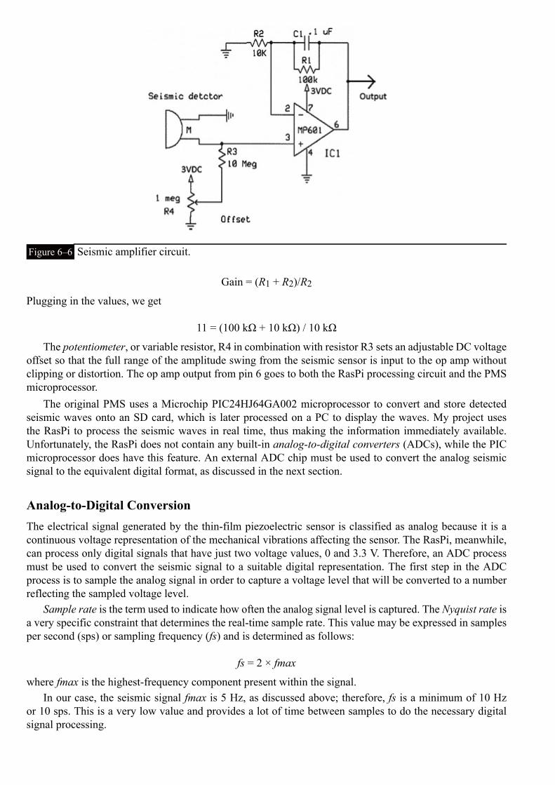
Figure 6–6 Seismic amplifier circuit.
Gain = (R1 + R2)/R2
Plugging in the values, we get
11 = (100 kΩ + 10 kΩ) / 10 kΩ
The potentiometer, or variable resistor, R4 in combination with resistor R3 sets an adjustable DC voltageoffset so that the full range of the amplitude swing from the seismic sensor is input to the op amp withoutclipping or distortion. The op amp output from pin 6 goes to both the RasPi processing circuit and the PMSmicroprocessor.
The original PMS uses a Microchip PIC24HJ64GA002 microprocessor to convert and store detectedseismic waves onto an SD card, which is later processed on a PC to display the waves. My project usesthe RasPi to process the seismic waves in real time, thus making the information immediately available.Unfortunately, the RasPi does not contain any built-in analog-to-digital converters (ADCs), while the PICmicroprocessor does have this feature. An external ADC chip must be used to convert the analog seismicsignal to the equivalent digital format, as discussed in the next section.
Analog-to-Digital ConversionThe electrical signal generated by the thin-film piezoelectric sensor is classified as analog because it is acontinuous voltage representation of the mechanical vibrations affecting the sensor. The RasPi, meanwhile,can process only digital signals that have just two voltage values, 0 and 3.3 V. Therefore, an ADC processmust be used to convert the seismic signal to a suitable digital representation. The first step in the ADCprocess is to sample the analog signal in order to capture a voltage level that will be converted to a numberreflecting the sampled voltage level.
Sample rate is the term used to indicate how often the analog signal level is captured. The Nyquist rate isa very specific constraint that determines the real-time sample rate. This value may be expressed in samplesper second (sps) or sampling frequency (fs) and is determined as follows:
fs = 2 × fmax
where fmax is the highest-frequency component present within the signal.In our case, the seismic signal fmax is 5 Hz, as discussed above; therefore, fs is a minimum of 10 Hz
or 10 sps. This is a very low value and provides a lot of time between samples to do the necessary digitalsignal processing.

The second step in the ADC process is to convert the sample voltage to a digital number. This can hap-pen in a variety of ways, all of which are dependent upon the type of ADC chip that is used. I used a Mi-crochip model MCP3008 that is described in the Microchip datasheet as a 10-bit, SAR ADC with SPI dataoutput. Translated, this means that the MCP3008 uses a successive approximation register (SAR) techniqueto create a 10-bit digital result that, in turn, is outputted in a serial data stream using the SPI protocol. Figure6–7 and a short discussion will help clarify this description.
Figure 6–7 MCP3008 functional block diagram.
The analog signal is first selected from one of eight channels that may be connected to the input channelmultiplexer. Using one channel at a time is called operating in a single-ended mode. The MCP3008 chan-nels can be paired to operate in a differential mode, if desired. A single configuration bit named SGL/DIFFselects single-ended or differential operating modes. Single-ended is the mode used in this project.
The selected multiplexer channel is then routed to a sample-and-hold circuit that is one of the two inputsto a comparator. The other input is from a digital-to-analog converter (DAC) that receives its input froma 10-bit SAR. Basically, the SAR starts at 0 and rapidly increments to a maximum of 1023, which is thelargest number that can be represented with 10 bits. Each increment increases the voltage appearing at theDAC’s comparator input. The comparator will trigger when the DAC’s voltage precisely equals the sampledvoltage, and this will stop the SAR from incrementing. The digital number that exists on the SAR at the mo-ment the comparator “trips” is the ADC value. This number is then outputted, one bit at a time through theSPI circuit discussed below. All this takes place between sample intervals. The actual voltage representedby the ADC value is a function of the reference voltage VREF connected to the MCP3008. In our case, VREFis 3.3 V; therefore, each bit represents 3.3/1024 or approximately 3.223 millivolts. For example, an ADCvalue of 500 would represent an actual voltage of 1.612 V, which was computed by multiplying .003223 by500.
Serial Peripheral InterfaceThe Serial Peripheral Interface (SPI) was introduced in Chap. 1 as a synchronous serial (SS) data link thatuses one master device and one or more slave devices. There are a minimum of four data lines used with theSPI, and Table 6–2 shows the names associated with the master (RasPi) and the slave (MCP3008) devices.

Table 6–2 SPI Data Line Descriptions
Figure 6–8 is a simplified block diagram showing the principal components used in an SPI data link.There are usually two shift registers involved in the data link, as shown in the figure. These registers maybe hardware or software, depending upon the devices involved. The RasPi implements its shift register insoftware, while the MCP3008 has a hardware shift register. In either case, the two shift registers form whatis known as an inter-chip circular buffer arrangement, which is the heart of the SPI.
Figure 6–8 SPI simplified block diagram.
Data communication is initiated by the master, which begins by selecting the required slave. The RasPiselects the MCP3008 by bringing the SS line to a LOW state or 0 V. During each clock cycle, the mastersends a bit to the slave that reads it from the MOSI line. Concurrently, the slave sends a bit to the master,which reads it from the MISO line. This operation is known as full-duplex communication, i.e., simultan-eous reading and writing between master and slave. Figure 6–9 shows the Master-Slave connection betweenthe RasPi and the MCP3008.
Figure 6–9 Test circuit SPI master/slave connections.
The clock frequency used is dependent primarily upon the slave’s response speed. The MCP3008 caneasily handle bit rates up to 3.6 MHz if powered at 5 V. Since we are using 3.3 V, the maximum rate is abit less at approximately 2 MHz. This is still very quick and will process the RasPi input without losing anydata.
The first clock pulse received by the MCP3008, with its CS pin held LOW and DIN pin HIGH, consti-tutes the start bit. The SGL/DIFF bit follows next and then three bits that represent the selected channel(s).

After these five bits have been received, the MCP3008 will sample the analog voltage during the next clockcycle.
The MCP3008 then outputs what is known as a low null bit that is disregarded by the RasPi. The fol-lowing 10 bits, each sent on a clock cycle, are the ADC value with the most significant bit (MSB) sent first,down to the least significant bit (LSB), which is sent last. The RasPi will then put the MCP3008 CS pinHIGH ending the ADC process.
Connecting and Testing the MCP3008 with the RasPiThe MCP3008 is connected to the RasPi using the Pi Cobbler prototype tool along with a solderless bread-board. Figure 6–10 is the schematic for this circuit. The physical setup is shown in Fig. 6–11.
Figure 6–10 RasPi and MCP3008 connection schematic.
Figure 6–11 RasPi and MCP3008 test setup.
There is a temporary test setup on the left side of the breadboard consisting of a potentiometer connectedbetween 3.3 V and ground. The ADC channel is connected to the tap, allowing a variable voltage that canbe used in the test.
The test software that produces a continuous stream of ADC values is shown below It is also availableon the book’s companion website, www.mhprofessional.com/raspi, as Test_ADC.py. The code follows the
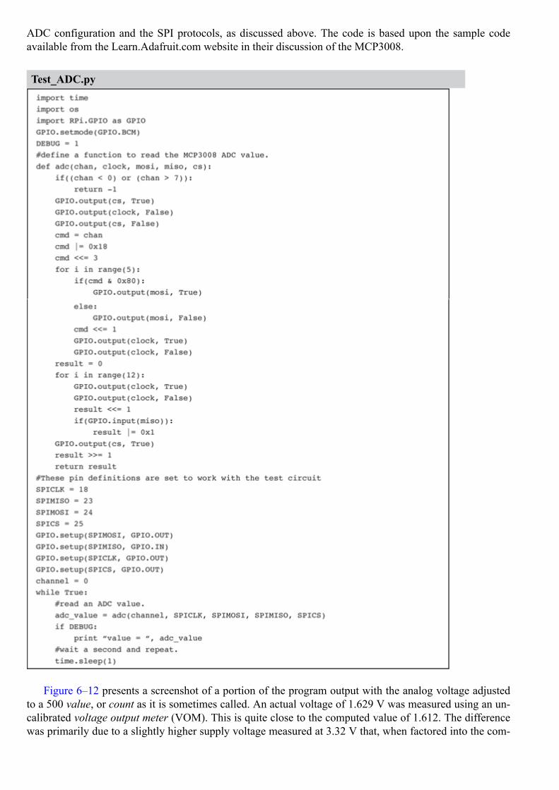
ADC configuration and the SPI protocols, as discussed above. The code is based upon the sample codeavailable from the Learn.Adafruit.com website in their discussion of the MCP3008.
Test_ADC.py
Figure 6–12 presents a screenshot of a portion of the program output with the analog voltage adjustedto a 500 value, or count as it is sometimes called. An actual voltage of 1.629 V was measured using an un-calibrated voltage output meter (VOM). This is quite close to the computed value of 1.612. The differencewas primarily due to a slightly higher supply voltage measured at 3.32 V that, when factored into the com-

putation, yields a 1.621 V or only a .008 V difference. This is equivalent to about 3 counts or +0.3%, whichis quite normal for this type of ADC.
Figure 6–12 Test_ADC.py program output.
The sharp-eyed reader may have noticed that the program does not rely on the built-in SPI functionalitybut instead implements a “bit-banged” interface that was discussed in Chap. 1 page 13. This approach wastaken because the Linux version used in this project did not directly implement the SPI protocol. It makesno functional difference which approach is taken other than that four GPIO pins are dedicated in the “bit-banged” version and are not otherwise available for other uses.
Connecting the Seismic DetectorIt is very simple to connect the PMS detector to the MCP3008 circuit. First disconnect and remove thetest circuit that was used in the above section. Then connect the PMS op-amp output and ground to theMCP3008 channel 0 and ground, respectively. Figure 6–13 shows the PMS connected to the MCP3008 cir-cuit that, in turn, is connected to the RasPi through the Pi Cobbler.

Figure 6–13 PMS connected to MCP3008/Pi Cobbler and RasPi..
The software also requires a slight modification because we are done with the initial testing and nowneed to collect some actual data from the seismic sensor. The code segment in the code listing titled“Test_ADC.py Segment (modification to allow the collection of seismic data)” on page 82 replaces all thecode starting at the line shown below.
The program with the new code inserted is available on the book’s website as Test_File_ADC.py. Thisnew program writes 1200 adc_values to a file named “myData,” which is located in the pi working dir-ectory, if you have not changed that location. Each value has a new-line character appended to enable thedata file to be easily imported into Excel for further analysis.
Python supports two ways to store data in a file by using either string or binary formats. The approachtaken in this program was to store the data as a sequence of strings, since we knew beforehand that the datawould be input to an Excel spreadsheet for further analysis. Storing data as strings consumes a lot of filespace as compared to storing the data in a binary format. The following code line shows how to store thedata in a binary format:
where wb is short for write binary. Of course, you would need to read in the data using the complementary“rb”, short for read binary. Not only that, but you need to restructure the program to keep track of the num-ber of bytes read to ensure that you don’t mix up the byte sequence and start reading “garbage.” You alsowill not need the line:
because the binary data is written in a contiguous byte stream that you, as the programmer, must decipher.This is another reason to use strings—it is much easier to debug the file contents.

This program takes two minutes to run, as the time between samples has been reset to .1 second. Recallthat this sample frequency is 10 Hz, which was discussed earlier as an optimal value for this application.Also note that “DEBUG = 0” is set, or you will get 1200 values displayed on your screen.
You should run Test_File_ADC.py while moderately shaking the PMS to create pseudoseismic activity.Do not be so vigorous as to have the brass pendulum strike the PVC pipe wall. The sensor is quite sensitive,so only gentle force is needed. We will be ready for some data analysis once the file is generated.
Seismic Data AnalysisCopy and paste the contents of the myData file into an Excel spreadsheet. There should be exactly 1200values in a single column. Each value represents the digitized value of a sample from the PMS detector. Thesamples were taken at an interval of .1 second; hence, the entire record spans two minutes. During this time,the PMS was subjected to some shaking, which provided the data for analysis. My Excel file is available onthe book’s companion website as Seismic.xlsx.
Figure 6–14 is a graph of an interesting portion of the data set. I selected it by visually scanning a graphof the entire record. This portion covers the first 200 samples. I next wanted to zoom in on, and examine infiner detail, a portion of this graph that covered X-axis numbers 139 to 168. Figure 6–15 shows this detail.
Figure 6–14 200 samples.
Figure 6–15 30 samples.

Test_ADC.py Segment (modification to allow collection of actual data)
Four peaks, located at X-axis numbers 8, 11, 14, and 18 in Fig. 6–15, are clearly visible. These peaksare separated in time by .3, .3, and .4 second, as each X-axis number represents a .1 second interval. Theaverage of the peak separation is .33 second, or equivalently, 3 Hz. This frequency is the apparent resonantfrequency of this PMS detector. It falls well within the acceptable frequency span discussed earlier and isvery suitable for seismic detection purposes.
The other analysis aspect that must be considered is the seismic magnitude, or Y axis. The highest valuerecorded within the two minute data record was slightly over 1000. Recall that the 10-bit MCP3008 canmeasure up to 1023, using a 3.3-V reference. Again, the maximum is OK, but we do have to be aware ofthe minimum value, or else the detector range will “bottom out”.
Examining the graphs indicates that the equilibrium level is around 500 counts. This is ideal in that anequal range, both high and low, is available to capture the sampled data. You may have to adjust your PMSif the equilibrium is not at this ideal level. That adjustment is easily done by turning the PMS offset poten-tiometer R4 until the displayed level is approximately 500. Refer to Fig. 6–6 to identify this control. Also,you can run the Test_ADC.py program to make this adjustment.
The final step in the analysis is to determine a valid warning or threshold level. This is somewhat sub-jective in that you need to set the level high enough to forestall false alerts, yet low enough to accuratelycapture real seismic events. Examining the data set again reveals that a level of 720 would probably suffice.It is sufficiently high to avoid random vibrations that may be caused by heavy trucks rolling nearby; yet itis low enough to capture real activity. In any case, the value can easily be reprogrammed, if needed.
Operational SystemThe primary requirement for an operational system is to create a warning if the detected seismic activityexceeds a preset or threshold level. I determined that a 720 level would be a good starting point. The fol-lowing program, Seismic_Monitor.py, will light an LED if a level of 720 or more is detected. The LED willremain on until reset by restarting the program. Seismic_Monitor.py is available on the book’s website.

Seismic_Monitor.py
The system functioned as expected with the LED being activated by a slight shake applied to the PMSdetector. Use the nano editor to change the line
to any value that you want to set as an appropriate threshold level.

SummaryThis chapter began with a brief review of seismology and how earthquakes are generated. It was pointedout that quakes produce both P- and S-waves with the P-waves being precursors to the destructive S-waves.
Next, I covered the basics of seismic sensor designs. The inverted pendulum was selected for this projectbecause it is both sensitive and very inexpensive.
The analog-to-digital conversion process was discussed, as it is required in order to convert the analogseismic signals to a digital format suitable for processing in the RasPi.
A thorough discussion of the Serial Peripheral Interface (SPI) followed. This is the interface throughwhich the data flows between the MCP3008 ADC chip and the RasPi.
Next the ADC chip was set up to function with the RasPi, using the Pi Cobbler prototyping tool. Alsoshown was a test program using “bit-banging” to control the ADC chip and implement the SPI protocol.
A seismic detector based on a kit called the “Poor Man’s Seismograph” (PMS) was connected and testedwith a program that collected data samples and stored them in a file on the RasPi file system. This data filewas then analyzed by using MS Excel to determine a realistic alarm level.
Finally, the project concluded with the demonstration of an operational system that lit an LED when theseismic level went above the trip level.
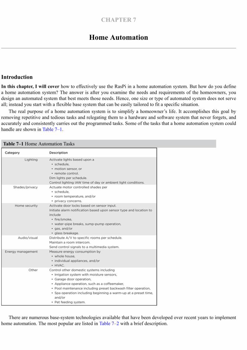
CHAPTER 7
Home Automation
IntroductionIn this chapter, I will cover how to effectively use the RasPi in a home automation system. But how do you definea home automation system? The answer is after you examine the needs and requirements of the homeowners, youdesign an automated system that best meets those needs. Hence, one size or type of automated system does not serveall; instead you start with a flexible base system that can be easily tailored to fit a specific situation.
The real purpose of a home automation system is to simplify a homeowner’s life. It accomplishes this goal byremoving repetitive and tedious tasks and relegating them to a hardware and software system that never forgets, andaccurately and consistently carries out the programmed tasks. Some of the tasks that a home automation system couldhandle are shown in Table 7–1.
Table 7–1 Home Automation Tasks
There are numerous base-system technologies available that have been developed over recent years to implementhome automation. The most popular are listed in Table 7–2 with a brief description.

Table 7–2 Popular Home Automation Technologies
I selected the Z-Wave technology to use in this project because it is wireless, very robust, based onstandards, and has components that are easily purchased and available from reliable manufacturers, includ-ing GE, Black & Decker, Schlage, ADT, and Draper. Anyone can purchase a Z-wave remote control andseveral nodes, and have an automation system functioning in a matter of minutes; the simplicity of settingup an automation system is what attracted me to this technology. This project replaces the remote with theRasPi and an attached Z-wave dongle. Of course, the RasPi is programmed to suit the homeowner’s needs.
There is no hardware construction involved in this project (the only physical task is to plug in a USBdongle), but that does not mean it is easy. A lot of software setup and configuration is involved in makingthe project run successfully. Of course, that’s part of the fun of working with the RasPi and Linux—manyfunctions can be done in software versus building hardware peripherals.
Z-Wave Mesh NetworkEach Z-Wave component or node contains a low-power radio-frequency (RF) transceiver. This radio op-erates in the Industrial, Scientific, and Medical (ISM) band at a frequency of 908.42 MHz in the UnitedStates and 860 MHz in Europe. These frequencies are far removed from other home wireless devices thattypically operate at 2.4 GHz. It is thus far less susceptible to causing, or being subjected to, interference.The outdoor range, or line of sight, is approximately 100 m or 300 ft. The indoor range is about 30 m or 90ft, due mainly to attenuation caused by the interior walls. Range extension is easily accomplished by simplyadding additional nodes into the home.
Since each node is a transceiver, it both receives and transmits digital messages, acting as a digital re-peater or “digipeater.” Digipeating creates a signal hop. There is, however, one major proviso: only fourhops are allowed. After that, the communications protocol automatically terminates the signal in a processknown as hop kill. This is done presumably to limit range and probably to remain in legal compliance withgovernmental regulations regarding low power, unlicensed operations.
Basics of Z-Wave Network OperationThe Z-Wave network, from its very beginning, was designed to be compliant with the ISO seven-layer net-work model. As such, its inherent design is based upon proven computer network concepts that are robust,efficient, and well understood by most system designers. Figure 7–1 shows the Z-Wave logical networkstack with the corresponding ISO layer number. All subsequent network software developed for the Z-Wavenetwork follows this model.

Figure 7–1 Z-Wave and ISO network layers.
Data sent through the Z-Wave network is in packets similar to the Ethernet format. Figure 7–2 showshow these packets are initially constituted at Layer 2 and subsequently modified at higher layers, as neededto suit the real-time network communication need.
Figure 7–2 Z-Wave network packets versus model layers.
A basic packet is created at the Data Link Layer 2 that starts with a synchronization preamble followedby a Start of Frame (SoF) byte. Next comes the payload, which can be up to 64 data bytes and is terminatedby an End of Frame (EoF) byte.
The Transport Layer 3 takes the basic packet and adds additional bytes, depending upon what is requiredin the communication process. Z-Wave is a connection-type network, similar to Ethernet, which has a veryrobust way of ensuring that packets get where they need to go. Layer 3 uses Acknowledgement (ACK) andNegative Acknowledgement (NACK) packets to maintain solid connections. A receiver node will send backan ACK packet to the sender if it successfully receives a data packet; otherwise, it sends back a NACK.This will continue until the original data packet is successfully sent or a preset number of retries is ex-ceeded. Each node also uses Collision Detection Multiple Access (CDMA) to determine when to transmiton the network signal lines. It is akin to the old-fashioned telephone party line, where a user first listens to

determine if anyone is talking and then starts talking if the line is free. In the case where a collision does oc-cur, each potential sender “backs off” a random amount of time (tens of milliseconds) and then tries again.Using ACKs and NACKs depends upon an error-checking capability, which is why two checksum bytesare included in every data packet. These bytes are used by the receiving node in a mathematical algorithmto determine if the received data packet was corrupted during transmission. There are many good tutorialsavailable on the Internet regarding checksums and error detection, if you are interested in digging furtherinto the subject.
Layer 3 with the help of network Layer 4 further refines the packets by identifying what the packet typeis, where it is going, and where it’s been, and then sets the data payload. There are five packet types used inthe Z-Wave network, which are described in Table 7–3.
Table 7–3 Z-Wave Packet Types
Layer 4 sets up the routing, thereby ensuring that the packets are sent along the correct paths to reachthe desired nodes. It also ensures that all nodes are repeating as configured. The routing configuration ismaintained in a table stored in the primary network controller. It is possible to have multiple controllers onthe network, but only one is designated as primary.
A simple network topology and descriptive routing table is shown in Fig. 7–3. A “1” in the routing tableindicates a node-to-node logical connection.
Figure 7–3 Network topology and routing table.
Every Z-Wave network has a four-byte ID called the Home ID. Each primary controller has this HomeID that slave nodes acquire when they are joined to the network. Every secondary controller also uses thissame ID when they are attached to the network. Individual slave nodes have a one-byte ID that is assignedby the primary controller when that node joins the network.
Network DevicesThere are two main device types that make up a Z-Wave network: controllers and slaves. Slaves are alsoknown as end-point devices because they can only respond to messages sent by the controllers. They typ-ically have built-in microprocessors with GPIO pins that control components, such as TRIACs, which turnAC power on and off. Figure 7–4 shows a Z-Wave enabled duplex outlet. It would be installed in the sameway as any ordinary duplex outlet would be installed, except that this outlet is also controllable using Z-Wave technology. The other big difference is that this outlet is much more expensive than a regular duplexoutlet; however, you don’t need many of them for most home automation setups.
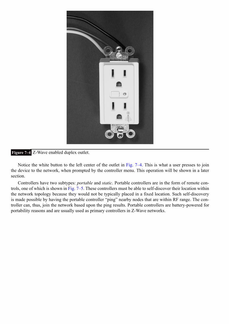
Figure 7–4 Z-Wave enabled duplex outlet.
Notice the white button to the left center of the outlet in Fig. 7–4. This is what a user presses to jointhe device to the network, when prompted by the controller menu. This operation will be shown in a latersection.
Controllers have two subtypes: portable and static. Portable controllers are in the form of remote con-trols, one of which is shown in Fig. 7–5. These controllers must be able to self-discover their location withinthe network topology because they would not be typically placed in a fixed location. Such self-discoveryis made possible by having the portable controller “ping” nearby nodes that are within RF range. The con-troller can, thus, join the network based upon the ping results. Portable controllers are battery-powered forportability reasons and are usually used as primary controllers in Z-Wave networks.

Figure 7–5 Portable Z-Wave controller.
The static controller is another subtype, and it so named because its logical location is fixed at the timeof the initial network configuration. It is usually powered from the AC mains and constantly listens for net-work traffic. A static controller can serve as a secondary controller in an advanced network configuration.The current network configuration may be stored in it, and if so, it is known as a Static Update Controller(SUC).
More often, the role a static controller plays is to serve as a bridge between non Z-Wave componentssuch as X-10 devices. In that configuration, the static controller serves as a virtual node between the X-10device and the Z-Wave network. The network can have up to 125 virtual nodes that help incorporate oldertechnologies into the modern Z-Wave system. Static controllers may also serve as TCP/IP gateways, thusallowing the network to connect to the Internet, if so desired. Finally, static controllers can serve as primarycontrollers in the configuration where the “normal” primaries act as proxies for the static control. This con-figuration type is known as an SUC ID Server (SIS). All told, there is an incredible amount of flexibility inZ-Wave network configurations.
The Z-Wave ChipThe original Z-Wave chip was designed and manufactured by Zensys, now known as Sigma Designs. Allcertified Z-Wave component manufacturers must use this authentic Z-Wave chip in their devices. This en-sures that any Z-Wave node properly joins the network and communicates with other nodes produced byother manufacturers. The Zensys chip design is discussed in this section because it forms the basis for the
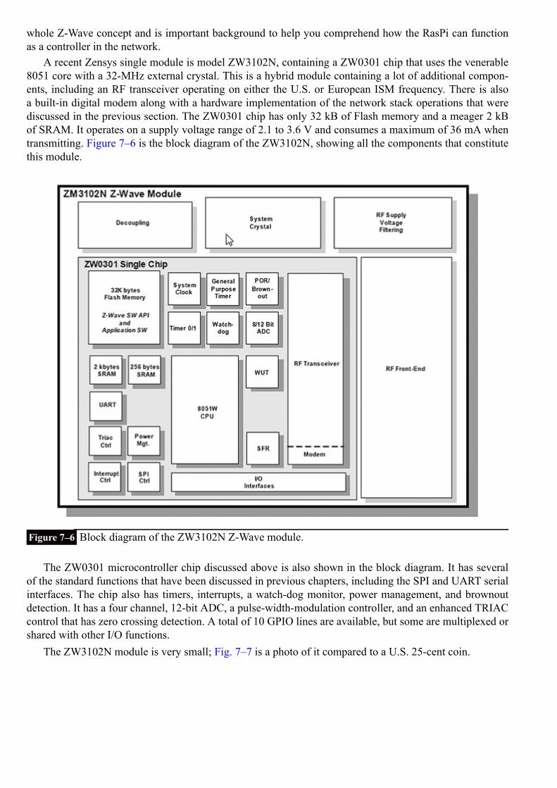
whole Z-Wave concept and is important background to help you comprehend how the RasPi can functionas a controller in the network.
A recent Zensys single module is model ZW3102N, containing a ZW0301 chip that uses the venerable8051 core with a 32-MHz external crystal. This is a hybrid module containing a lot of additional compon-ents, including an RF transceiver operating on either the U.S. or European ISM frequency. There is alsoa built-in digital modem along with a hardware implementation of the network stack operations that werediscussed in the previous section. The ZW0301 chip has only 32 kB of Flash memory and a meager 2 kBof SRAM. It operates on a supply voltage range of 2.1 to 3.6 V and consumes a maximum of 36 mA whentransmitting. Figure 7–6 is the block diagram of the ZW3102N, showing all the components that constitutethis module.
Figure 7–6 Block diagram of the ZW3102N Z-Wave module.
The ZW0301 microcontroller chip discussed above is also shown in the block diagram. It has severalof the standard functions that have been discussed in previous chapters, including the SPI and UART serialinterfaces. The chip also has timers, interrupts, a watch-dog monitor, power management, and brownoutdetection. It has a four channel, 12-bit ADC, a pulse-width-modulation controller, and an enhanced TRIACcontrol that has zero crossing detection. A total of 10 GPIO lines are available, but some are multiplexed orshared with other I/O functions.
The ZW3102N module is very small; Fig. 7–7 is a photo of it compared to a U.S. 25-cent coin.

Figure 7–7 ZW3102N module compared to a U.S. 25-cent coin.
The module does need an external antenna and a few capacitors and inductors to complete a Z-Wavedevice installation. The software is fixed in the flash memory and is not available for examination or modi-fication. This is where this RasPi project will open up the Z-Wave network so that you have a chance toexperiment with various configurations and monitor network traffic. But first, I would like to demonstratea simple Z-Wave network that uses a portable controller (Fig. 7–5) along with two nodes, one being theduplex outlet (Fig. 7–4) and the other being an outdoor module shown in Fig. 7–8. Notice the black but-ton located on the top of the device in Fig. 7–8. The user presses it to join the device to the network whenprompted by the controller menu.
Figure 7–8 Z-Wave outdoor module.
Notice the black button located on the top of the device in Fig. 7–8. The user presses it to join the deviceto the network when prompted by the controller menu.
My test network slaves will be made up of the duplex outlet and the outdoor module, each controlling asmall table lamp. The duplex outlet will actually be connected to a power cord plugged into a regular outletfor this temporary test arrangement. Figure 7–9 shows the test setup on my dining room table.

Figure 7–9 Z-Wave test system.
At first, I arbitrarily assigned a device number 4 to the duplex outlet and a device number 8 to the out-door module. I then proceeded to turn the lamps on and off, and everything worked just fine. I was also ableto control both devices simultaneously by selecting the “All” mode on the remote.
The next part of the test was a bit harder, as I have a smaller home with an open plan layout, meaningfewer interior walls than in the average cape-style home. I was finally able to place the outdoor moduledevice in the basement and the duplex outlet on the first floor and then operated the controller in a secondfloor bedroom. I was not able to turn on the basement module without having the first-floor module pluggedin. This proved that the first-floor module was digipeating and forwarding the control packets to the mod-ule located in the basement. The controller showed “Failure” on its LCD screen with the first-floor moduleunplugged, which indicated that no ACKs were being received. Obviously, no NACKs could be sent, sincethe first-floor module was unpowered and the basement module was out of range.
Setting up the test arrangement was an extremely simple process, which shows how well the high-techZ-Wave network functions in the “background,” while also providing the homeowner with a very easy anduseful interface. But that’s not what we are after. I want to demonstrate how the RasPi interfaces with aZ-Wave network and what “neat” experiments can be accomplished.
RasPi and Z-Wave InterfaceConnecting a RasPi to a Z-Wave network requires the use of a Z-Wave USB dongle. One such device madeby Aeon Labs, called the Z-Stick, is shown in Fig. 7–10.

Figure 7–10 Aeon Labs Z-Stick.
The Z-Stick incorporates a Zensys module and a USB interface chip along with some additional firm-ware to make the two components work together. It also has an internal rechargeable battery that enables thestorage of firmware updates and configuration data. The Z-Stick has three operating modes that you shouldknow:
1. Inclusion—This mode adds or includes Z-wave devices into the network. To add a device:
a. Unplug the Z-Stick from the USB connector.b. Press the large button on the Z-Stick. The Z-Stick LED will start to blink slowly.c. Go to the device that you wish to add (while continuing to press the large Z-Stick button) and press
and release the device’s button.d. The Z-Stick LED will blink rapidly for several seconds, then glow steadily for three seconds, and fi-
nally return to a slow blinking state. The device has been added to the network.
2. Removal—This mode will remove or exclude Z-wave devices from the network. To remove a device:
a. Unplug the Z-Stick from the USB connector.b. Press and hold the large button on the Z-Stick for about three seconds. The Z-Stick LED will start to
blink slowly and then transition to a fast blink.c. Go to the device that you wish to remove (while continuing to press the large Z-Stick button) and
press and release the device’s button.d. The Z-Stick LED will then glow steadily for three seconds and finally return to a fast blinking state.
The device has been removed from the network.
3. SerialAPI—This is the mode where the Z-Stick acts as the portal between the RasPi and the Z-Wavenetwork. Simply plug it into a powered-hub USB connector. The RasPi probably does not have suffi-cient power for the Z-Stick. The RasPi software will now take control of the Z-Wave network.
I now have to take a brief detour from the Z-Wave to introduce the SSH login process, since I use thatin establishing the control software environment.
SSH LoginIn this section, I will show you how to log into the RasPi by using a network connection, as I mentioned inChap. 5. The Wheezy Linux distribution, as well as many others, includes a great service known as SSH,short for Secure Shell. It is a network protocol that uses cryptographic means to establish secure data com-munication between two networked computers connected via a logical, secure channel over a physical, in-secure network. SSH uses both server and client programs to accomplish the connection.

One of the questions you will be asked when first configuring your RasPi is whether or not to start sshdupon bootup. I recommend that you answer “yes” as that automatically starts the SSH daemon each timeyou start the RasPi. The second portion of the connection is the client program, which is highly depend-ent upon what type of computer you are using to connect to the RasPi. I recommend using putty.exe, sincemost readers will be using a Windows®-based machine. putty is freely available from a variety of Internetsources, so I would recommend a Google search to locate a good download mirror.
You should see the Fig. 7–11 screenshot, assuming that you answered “yes” to the sshd question andhave downloaded and are running putty on a Windows-based computer connected to the same network thatconnects to the RasPi. Don’t be concerned with the host name that appears in the screenshot; I will get tothat shortly.
Figure 7–11 putty screenshot.
When you click on the Open button at the bottom of the putty screen, you will see in Fig. 7–12, a screen-shot of a RasPi terminal window asking, in this case, for a login password.
Figure 7–12 Raspberry Pi terminal window.

At this point, you are in a RasPi terminal window session. It is absolutely no different from looking ata monitor connected directly to the RasPi and using a locally connected keyboard and mouse. This trans-parency is what makes SSH so great—it allows you to login remotely to the RasPi without being concernedwith any minutia about the connection. You may type in any normal command and have the RasPi respondas appropriate.
I will now return to the Z-Wave control software discussion, now that you are a bit familiar with SSH.
Open Z-Wave SoftwareI took a very easy approach to implementing the control software between the RasPi and the Z-Wave net-work. I used a prebuilt Wheezy Raspian image kindly made freely available by Thomas Loughlin at ht-tp://thomasloughlin.com/new-open-zwave-image-for-raspberry-pi/. Simply download the image and createa new SD, card using the procedures discussed in Chap. 1. While Thomas has carefully detailed the stepsrequired to get the RasPi working with a Z-Wave network, I will paraphrase and use some figures to helpclarify the somewhat involved process.
I used a “headless” approach, meaning I logged into the RasPi using putty. Headless is a bit of networkjargon meaning you don’t need a local monitor or keyboard for the RasPi because you will login remotelyusing the RasPi as a server. The step-by-step procedure for starting the Z-Wave RasPi network is:
1. First add one or two devices to the network as described above. This establishes a beginning configura-tion that enables you to see and control some devices.
2. Plug the Z-Stick into a powered hub connected to an unpowered RasPi that has the downloaded OpenZ-Wave image.
3. Power on the RasPi and wait a minute or so. Remember, we are running headless and are not lookingat a monitor screen connected to the RasPi.
4. In the opening putty screen, enter
as a host name. (Fig. 7–11)
5. The password is the regular one,
6. A terminal window (Fig. 7–12) will appear.
7. You are now ready to take one of two approaches to monitor and control the Z-Wave network.
lightscontrol ServerOne of two server applications may be run at this point. The first is a web app named “lightscontrol” thatwas created by Conrad Vassallo and can be downloaded from the website, http://conradvassallo.com/cat-egory/open-zwave-controller/. This will be the one that I use. The second approach is a bare bones serverapp that Thomas created to test the Z-Wave network. I will discuss that server after demonstrating thelightscontrol server. All you need to do to start this service is type the following at the command lineprompt:

This starts the lightscontrol server. Figure 7–13 shows the lengthy preamble to the lightscontrol serverweb app.
Figure 7–13 lightscontrol web server preamble screenshot.
Now, you should minimize the terminal control window, keeping in mind that there is still an underlyingactive SSH connection that will allow you to input commands to the RasPi. We are going to need putty afterexperimenting with the first web server. Next, open a browser and enter this for the URL:
This should take you to the initial lightscontrol server page, as shown in Fig. 7–14.

Figure 7–14 lightscontrol server page.
In my case, I had initially set up one device, a GE outdoor power module controlling a lamp, as I dis-cussed earlier in the chapter. Table 7–4 shows the web page attributes for this device.
Table 7–4 Z-Wave Device Attributes
Clicking on the web page ON and OFF buttons turned the corresponding Z-Wave controlled lamp onand off, thus confirming that all the software and network connections were properly operating.
I have included some screenshots of the web app configuration pages to help illustrate how to configurea Z-Wave network to support typical home automation tasks. There is no professional documentationprovided with this open-source project, which is often the case, but I am not complaining and am completelyappreciative of the tremendous unpaid effort that goes into such project development done for the generalgood.
Figure 7–15 is a screenshot of the Scenes web page where one or more devices can be grouped collect-ively to support a common event happening in the home, such as Wake Up, TV, Kids Sleeping, etc.
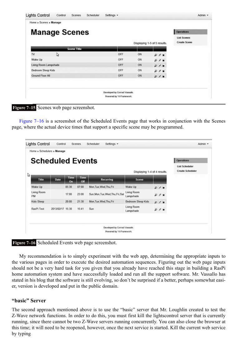
Figure 7–15 Scenes web page screenshot.
Figure 7–16 is a screenshot of the Scheduled Events page that works in conjunction with the Scenespage, where the actual device times that support a specific scene may be programmed.
Figure 7–16 Scheduled Events web page screenshot.
My recommendation is to simply experiment with the web app, determining the appropriate inputs tothe various pages in order to execute the desired automation sequences. Figuring out the web page inputsshould not be a very hard task for you given that you already have reached this stage in building a RasPihome automation system and have successfully loaded and run all the support software. Mr. Vassallo hasstated in his blog that the software is still evolving, so don’t be surprised if a better, perhaps somewhat easi-er, version is developed and put in the public domain.
“basic” ServerThe second approach mentioned above is to use the “basic” server that Mr. Loughlin created to test theZ-Wave network functions. In order to do this, you must first kill the lightscontrol server that is currentlyrunning, since there cannot be two Z-Wave servers running concurrently. You can also close the browser atthis time; it will need to be reopened, however, once the next service is started. Kill the current web serviceby typing

at the SSH command line. This is the reason why I did not want you to stop running putty.To start the “basic” server, simply enter the following at the command line:
Once that is done, minimize putty and open the browser going to this website:
This should take you to the “basic” server page, as shown in Fig. 7–17.
Figure 7–17 “basic” server web page.
All devices that have been added to the Z-Wave network and stored in the Z-Stick memory will be dis-played on this page. As you can see, the only device displayed is the outdoor power module that was shownin the previous web server demo. The light may be turned on and off by clicking on the icon. There is noprovision for setting Scenes or preprogrammed times, as this is just a very functional web test app. The es-sential device attributes are shown as text in the middle of the page.
I next wanted to test this system to see how a different device type would be accommodated. To do this,I shut everything down and then added a new device to the network. This was a battery-operated, Z-Waveenabled motion sensor, as shown in Fig. 7–18.

Figure 7–18 Battery-operated, Z-Wave motion sensor.
I next restarted the “basic” web service and loaded the appropriate web page. Figure 7–19 shows thisnew page with both the outdoor module and the motion sensor displayed.
Figure 7–19 Revised “basic” server web page.
The motion sensor sends data back to the Z-Stick, which I confirmed by waving my hand in front of thesensor and observing that the state shown on the sensor window changed from off to on. Note, I did haveto reload the page to observe this change. Also, the essential device attributes shown on the page reflect theselected device.
SummaryI started this chapter with a definition of home automation and provided a list of representative tasks thatwould fall under the broad umbrella that comprises home automation.
Next followed a discussion of the underlying base technologies that support home automation imple-mentations. I provided a rationale for selecting the Z-Wave protocol: it is a modern, highly flexible systemthat is very easy to configure and lends itself quite well to a simple RasPi interface connection.
Two representative Z-Wave devices were next described along with a working, small-scale Z-Wave net-work. Then we conducted a network demonstration by using a commercial remote control device.
The core Z-Wave chip was discussed to provide you with a better understanding of how the overall net-work functions and how devices are highly dependent upon the chip functions, which can be added seam-lessly to the network.
The Z-Stick that enables the actual RasPi to Z-Wave interface was shown along with the driver software.However, before discussing the software, I showed you the highly useful SSH remote login procedure.
The open Z-Wave software package was shown with two variations for the web application side: 1)lightscontrol and 2) “basic.”
Some simple tasks such as turning a lamp on and off were demonstrated as well as the ability to sensemotion in a room.

CHAPTER 8
Home Security Controller
IntroductionFor this chapter’s project, you’ll learn how to connect a webcam to the RasPi so that a homeowner can view a se-lected home area when an intrusion signal is detected by the RasPi. A laser trip device serves as the intrusion sensor.When the RasPi detects an intrusion signal, the RasPi will send an e-mail notification to a preset e-mail address to noti-fy the homeowner that the laser has tripped, thus indicating that a possible intruder is on the premises. The homeownerwill then open a browser, go to a website where the webcam video is available, and examine the ongoing activity. Thehomeowner could then determine whether to call the police or simply to disregard the alarm, if it had been innocuouslytripped.
Motion is the name of the software package installed on the RasPi. It is a very sophisticated suite of vision ap-plications that provides the project’s webcam monitoring function. Many other features are also available and will bediscussed in the software section.
Webcam SelectionThe webcam used in this project is a fairly new Logitech C920, as shown in Fig. 8–1.
Figure 8–1 Logitech C920 webcam.
The webcam has a high definition camera capable of producing excellent videos; however, the software used withit in this project will limit its performance. With that in mind, note that many different webcams may be used. In ad-dition, the video requirements are quite low, and the Linux Raspian distribution will automatically detect quite a fewtypes of webcams, including many older ones. If you already own a webcam, my suggestion is to plug it into a USBport and then type the following into a command line:

Figure 8–2 is a screenshot of the command’s output. Device 008 is the webcam and the other Logitechdevice listed is a keyboard. If in doubt about which device is the right one, when multiple devices from thesame manufacturer show up, simply unplug the device and rerun the command to see which one disappears.
Figure 8–2 lsusb output screenshot.
One key point I discovered in creating this project is that the webcam has to be directly plugged intoone of the two RasPi USB ports. The webcam was not detected by the software when it was connected toa powered-hub USB connector. I am not sure why this happened but it may be related to an issue with thehub power supply.
Protected Security ZoneFigure 8–3 is an actual image capture from the webcam. It shows the protected zone, which, in this case, isthe exit to my home’s back deck. I will discuss how images may be captured later in the software section. Itis now important to show the intended protection zone because it greatly affects how the laser trip assemblywill be deployed as part of the overall security scheme.

Figure 8–3 Protected Zone.
Laser Trip AssemblyI reused the same laser trip device that I used in the camera controller project. Figure 8–4 shows this as-sembly mounted on a single piece of Lexan. The only difference in this trip setup is that I used a mirror toreflect the beam back to the detector’s phototransistor when an object interrupts the beam between the laserpointer and the detector in the protected zone. The height at which you mount the laser and the detectorboard is your choice, but I found that about four inches above the floor worked quite nicely. The total pathlength of the laser beam was about 14 feet, which was not an issue with this system.
Figure 8–4 Laser trip assembly.
Figure 8–5 shows the laser trip assembly operating in the evening. This photo was taken with a flash toclearly show all the components, including the mirror to the right.

Figure 8–5 Operational laser trip assembly.
I took another photo, but this time in almost total darkness. In Fig. 8–6, you can see the emitted laserbeam and a dot of reflected light in the mirror; however, you cannot see the projected laser beam. This, ofcourse, conflicts with what you see in the movies when the hero (or bad guy) attempts to get past the laserbeams protecting the secret vault or whatever. I would actually have to put smoke or dust in the beam’s pathto see it, which would have caused much consternation in my household.
Figure 8–6 An elapsed-time photo of the laser trip assembly in operation.
The extra red light seen on the detector side is the returned beam reflecting off of the nearby white trimboard. You could place some black cloth behind the detector if a more stealthy installation is desired.
The trip system functioned very well, never missing my exiting or returning. Another trip assemblycould be stationed at four feet above the floor if you are worried about intruders simply stepping over theinvisible beam. My philosophy regarding such matters is that criminals will simply go to easier targets ifthey suspect or detect that a relatively sophisticated intrusion system is in place and operational.
RasPi Interface to the Laser Trip AssemblyI have used the same relay switched circuit that was used in the camera control project. The schematic isshown in Fig. 8–7.
Figure 8–7 Schematic of relay switched interface for the laser trip assembly.
The circuit is extremely simple, yet highly reliable—two attributes that are important in security sys-tems. The relay contacts are normally open, which means that the GPIO pin will be in a high state due to the10 kΩ resistor tied to 3.3 V. The pin will go to ground or to 0 V when the detector is tripped. The software,
thus, has to check periodically for a low state on the selected GPIO pin and then initiate all the desired ac-tions, which will be discussed in the software section.
Motion Software PackageI selected a software package named Motion to enable remote viewing of the webcam. This is a compre-hensive package that contains many features, far more than could be covered in this chapter. Being able touse this package from among the others available is why the RasPi is so useful. Creating similar softwarefor a more traditional board, such as one from the Arduino series, would be a substantial undertaking, if itis even possible.
Motion also has the capability of detecting changes in the images from frame to frame, thus triggeringan alarm based solely on real-time video analysis. I thought about using this feature but eventually decidedupon the simpler approach of using an external trip system. Detecting an intrusion event based on the videoalone requires the RasPi to be almost solely committed to vision processing, which could affect the availab-ility of the video for remote viewing. This may have been an unwarranted decision, but remember that theMotion software was created years before the RasPi came on the scene and probably was based on usingmuch higher-clock-speed PCs.
The key feature that is used from the Motion package is the built-in web server. This server receivesthe video stream from the webcam and sends it off in TCP/IP format over a predefined port. All you needto remotely view the webcam video is a browser pointed to the RasPi IP address and port number, nothingmore. This feature makes the viewing exercise extremely simple. But there is more: Motion provides forusing more than one webcam. You can set up multiple webcams, each with its own port number, so that itcan monitor multiple locations throughout the home. Each webcam video feed is handled by what is knownas a thread within the Motion software. I saw provisions for four threads in the Motion configuration filefrom which I presume four webcams could be handled. However, I seriously wonder if the RasPi has theprocessing power to manage four simultaneous video feeds. In any case, this project is only concerned withone feed that I know works very well.
Motion FeaturesMotion has a substantial number of features that enable it to accomplish an amazing number of functions.The user manual is on-line at http://www.lavrsen.dk/foswiki/bin/view/Motion/WebHome, and it is over 100pages in length. It would take a complete book to document all the features. However, the configurationfile itself contains many self-documenting comments that should help you explore some of the additionalfeatures of this software package.
A portion of the configuration file dealing with motion detection is listed on page 107 to illustrate whatI mean.
Motion SetupYou must, of course, install the Motion package before using it. I would strongly suggest that you updateand upgrade your distribution before installing Motion. Simply type the following at a command lineprompt to update and upgrade the Linux distribution in use:
Be patient, since the updates and upgrades can take a bit of time if there are many to install.Next install Motion by typing:
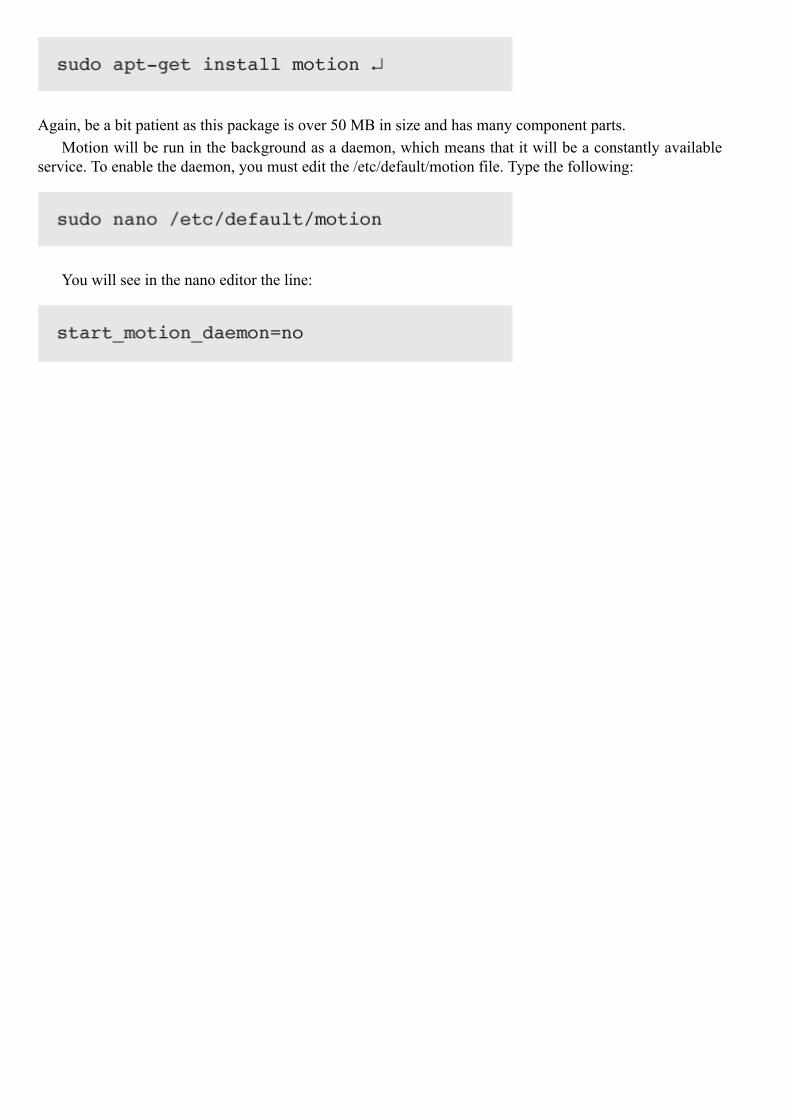
Again, be a bit patient as this package is over 50 MB in size and has many component parts.Motion will be run in the background as a daemon, which means that it will be a constantly available
service. To enable the daemon, you must edit the /etc/default/motion file. Type the following:
You will see in the nano editor the line:

Motion Detection Settings
Change the “no” to “yes,” then save the nano buffer and exit the editor.

Next comes Motion’s configuration file. Motion has no GUI; it is totally configured by making changesto its configuration file, /etc/motion/motion.conf. This is a very big text file—well over 600 lines—althoughmuch of file’s contents are comments inserted to help the user. Fortunately only a few changes are necessaryfor this project. In Table 8–1, I provide the changes to be made to the configuration file section, but I do notgive you step-by-step instructions because it should be fairly obvious by now how the editor functions.
Table 8–1 Motion Configuration File Changes
Again, start a nano editor session as follows:
Save the changes and exit the nano editor. Now, you must start the Motion server, which is done by typ-ing:
One nice feature of having the Motion web server running as a daemon is that it is automatically startedeach time you boot the RasPi. You may also stop or restart the service by typing:
That’s it for the changes to make in the configuration file. I do want to briefly discuss why these changeswere made. The change from daemon off to daemon on is obvious—it was needed to run Motion as a dae-mon. The next change—to make the port number 8081—is a bit historical, since the Motion web servicehas traditionally been assigned to this port. It is not a required port number and you can easily change itto any number that you desire as long as it is greater than 1024 and less than 65535. This range avoids the“well known ports” and goes to the maximum possible port number. My recommendation is to leave it at8081.
The next change concerns localhost operation. Localhost refers to the same machine that is hosting theMotion web server. No other system can access the webcam if you restrict the service to localhost; hence itmust be turned off.
The next two changes are similar to what was discussed above but are concerned with the remote controlfunctions of the webcam. I do not enable any remote control functions, such as webcam panning or tilting inthis project, but it is certainly doable. I suggest, however, that you simply keep the port number as assignedand disable the localhost operation.

Webcam ViewingIt is now time to test the remote webcam viewing functionality. You will need a separate computer on thesame network that the RasPi is connected to. You will also need the RasPi IP address. It does not matter ifthe RasPi is connected via an Ethernet cable or by a Wi-Fi wireless adapter. My suggestion is to login intoyour network router and click on “Attached Devices.” The local IP address for the RasPi should appear inthe appropriate list. My Netgear router has separate lists for wired and wireless devices connected to thenetwork. Yours might be slightly different but should show something similar to Fig. 8–8.
Figure 8–8 Router attached devices list.
The entry RASPBERRYPI has the IP 192.168.1.21 on the wired portion of my home network. This isall I need to remotely view the webcam. I just have to type 192.168.1.21:8081 into a browser on anothernetworked computer to view the real-time webcam video stream. Figure 8–9 is a screen capture of the videofeed from the RasPi webcam. I used the robot car from Chaps. 12 and 13 as the subject.
Figure 8–9 Video stream screen capture.
E-Mail NotificationThe next step in this project is to discuss the software that sends out an e-mail when the laser trip system istriggered. You will need a working Gmail account in order to have this software function because it uses aPython package named smtplib, which, in turn, uses Google’s freely available Gmail smtp server. The soft-ware is also designed to run in a home network using a router. I will show you how to obtain the publicfacing IP address that is dynamically assigned by your Internet Service Provider (ISP).
The Python code that sends out the e-mail notification is shown on page 110.
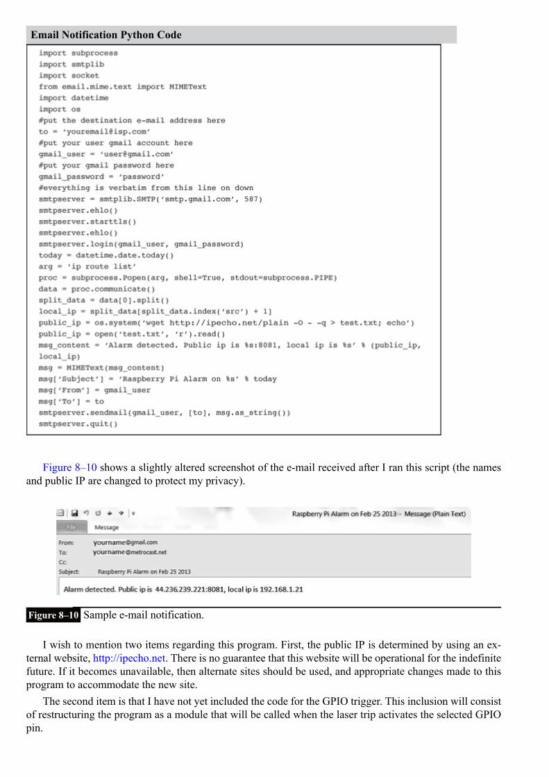
Email Notification Python Code
Figure 8–10 shows a slightly altered screenshot of the e-mail received after I ran this script (the namesand public IP are changed to protect my privacy).
Figure 8–10 Sample e-mail notification.
I wish to mention two items regarding this program. First, the public IP is determined by using an ex-ternal website, http://ipecho.net. There is no guarantee that this website will be operational for the indefinitefuture. If it becomes unavailable, then alternate sites should be used, and appropriate changes made to thisprogram to accommodate the new site.
The second item is that I have not yet included the code for the GPIO trigger. This inclusion will consistof restructuring the program as a module that will be called when the laser trip activates the selected GPIOpin.
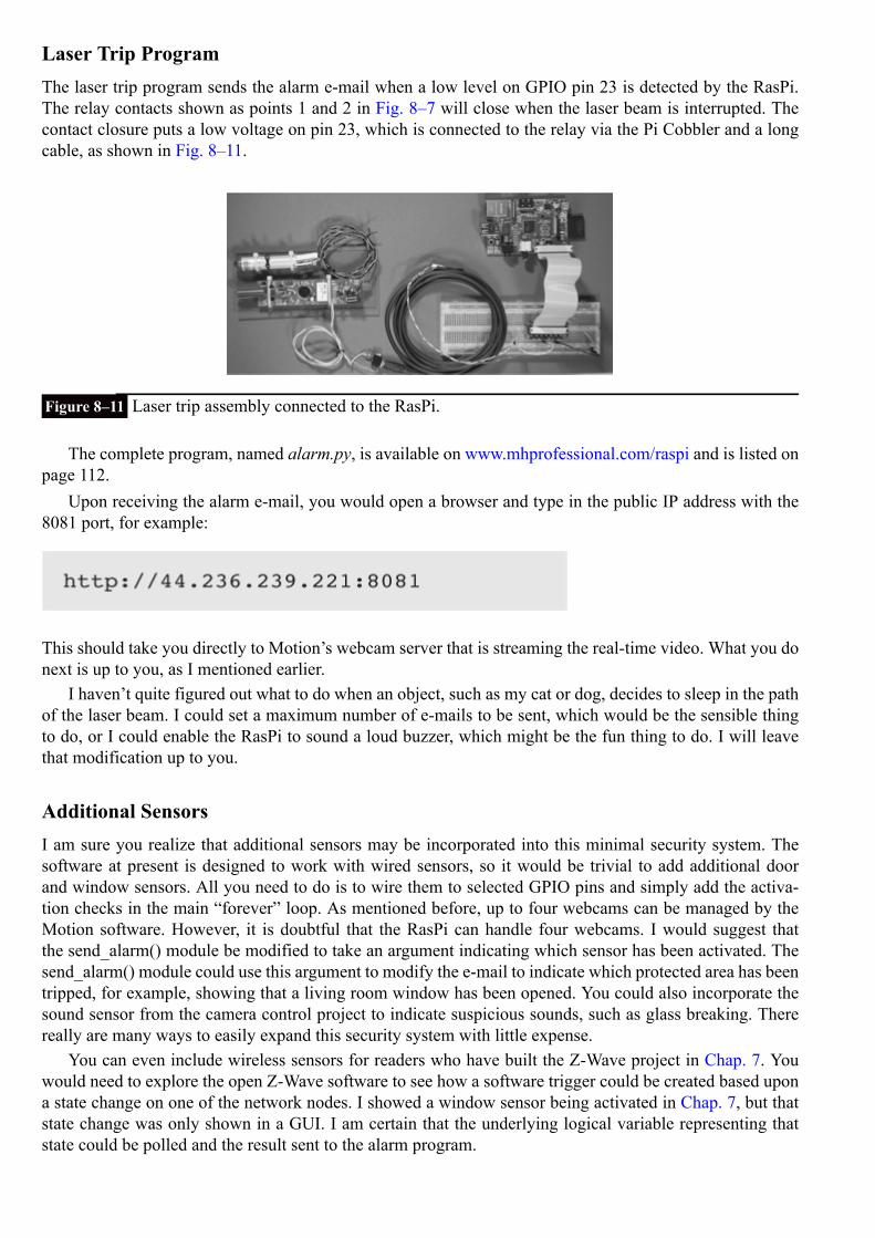
Laser Trip ProgramThe laser trip program sends the alarm e-mail when a low level on GPIO pin 23 is detected by the RasPi.The relay contacts shown as points 1 and 2 in Fig. 8–7 will close when the laser beam is interrupted. Thecontact closure puts a low voltage on pin 23, which is connected to the relay via the Pi Cobbler and a longcable, as shown in Fig. 8–11.
Figure 8–11 Laser trip assembly connected to the RasPi.
The complete program, named alarm.py, is available on www.mhprofessional.com/raspi and is listed onpage 112.
Upon receiving the alarm e-mail, you would open a browser and type in the public IP address with the8081 port, for example:
This should take you directly to Motion’s webcam server that is streaming the real-time video. What you donext is up to you, as I mentioned earlier.
I haven’t quite figured out what to do when an object, such as my cat or dog, decides to sleep in the pathof the laser beam. I could set a maximum number of e-mails to be sent, which would be the sensible thingto do, or I could enable the RasPi to sound a loud buzzer, which might be the fun thing to do. I will leavethat modification up to you.
Additional SensorsI am sure you realize that additional sensors may be incorporated into this minimal security system. Thesoftware at present is designed to work with wired sensors, so it would be trivial to add additional doorand window sensors. All you need to do is to wire them to selected GPIO pins and simply add the activa-tion checks in the main “forever” loop. As mentioned before, up to four webcams can be managed by theMotion software. However, it is doubtful that the RasPi can handle four webcams. I would suggest thatthe send_alarm() module be modified to take an argument indicating which sensor has been activated. Thesend_alarm() module could use this argument to modify the e-mail to indicate which protected area has beentripped, for example, showing that a living room window has been opened. You could also incorporate thesound sensor from the camera control project to indicate suspicious sounds, such as glass breaking. Therereally are many ways to easily expand this security system with little expense.
You can even include wireless sensors for readers who have built the Z-Wave project in Chap. 7. Youwould need to explore the open Z-Wave software to see how a software trigger could be created based upona state change on one of the network nodes. I showed a window sensor being activated in Chap. 7, but thatstate change was only shown in a GUI. I am certain that the underlying logical variable representing thatstate could be polled and the result sent to the alarm program.

alarm.py
SummaryI started this chapter by discussing the selection of the webcam to be used in the surveillance of the securityzone. It turns out that Raspian Wheezy, the RasPi Linux distribution used, has drivers for different manu-facturers including many older models.
The laser trip assembly used in the camera controller project was shown in its new role as the primaryintrusion sensor. I reused the same interface circuit between the RasPi and the camera controller because itwas simple and functional for this project.
The key software package, Motion, was discussed next. I used only a small portion of its capability, thatbeing the webcam server. The Motion setup for the RasPi was discussed along with a demonstration of anactual webcam stream.

I introduced a notification program that will send an e-mail to a designated recipient that contains boththe public and local IP addresses currently associated with the RasPi. This program was then incorporatedinto an overall program that sent the e-mail when the RasPi detected an intrusion signal.
Finally, I concluded with a brief discussion about future modifications and the ease with which addi-tional sensors could be added to expand the system.
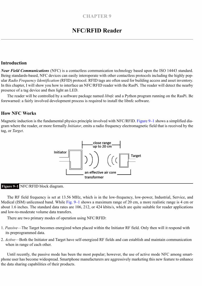
CHAPTER 9
NFC/RFID Reader
IntroductionNear Field Communications (NFC) is a contactless communication technology based upon the ISO 14443 standard.Being standards-based, NFC devices can easily interoperate with other contactless protocols including the highly pop-ular Radio Frequency Identification (RFID) protocol. RFID tags are often used for building access and asset inventory.In this chapter, I will show you how to interface an NFC/RFID reader with the RasPi. The reader will detect the nearbypresence of a tag device and then light an LED.
The reader will be controlled by a software package named libnfc and a Python program running on the RasPi. Beforewarned: a fairly involved development process is required to install the libnfc software.
How NFC WorksMagnetic induction is the fundamental physics principle involved with NFC/RFID. Figure 9–1 shows a simplified dia-gram where the reader, or more formally Initiator, emits a radio frequency electromagnetic field that is received by thetag, or Target.
Figure 9–1 NFC/RFID block diagram.
The RF field frequency is set at 13.56 MHz, which is in the low-frequency, low-power, Industrial, Service, andMedical (ISM) unlicensed band. While Fig. 9–1 shows a maximum range of 20 cm, a more realistic range is 4 cm orabout 1.6 inches. The standard data rates are 106, 212, or 424 kbits/s, which are quite suitable for reader applicationsand low-to-moderate volume data transfers.
There are two primary modes of operation using NFC/RFID:
1. Passive—The Target becomes energized when placed within the Initiator RF field. Only then will it respond withits preprogrammed data.
2. Active—Both the Initiator and Target have self-energized RF fields and can establish and maintain communicationwhen in range of each other.
Until recently, the passive mode has been the most popular; however, the use of active mode NFC among smart-phone user has become widespread. Smartphone manufacturers are aggressively marketing this new feature to enhancethe data sharing capabilities of their products.
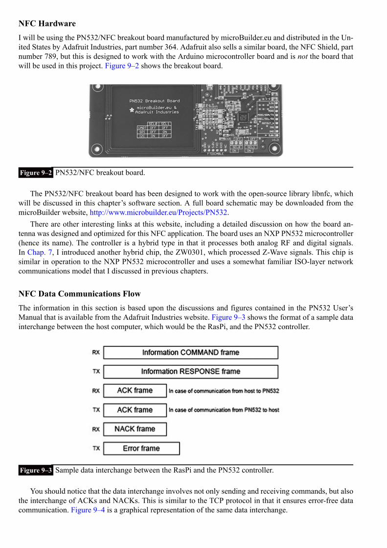
NFC HardwareI will be using the PN532/NFC breakout board manufactured by microBuilder.eu and distributed in the Un-ited States by Adafruit Industries, part number 364. Adafruit also sells a similar board, the NFC Shield, partnumber 789, but this is designed to work with the Arduino microcontroller board and is not the board thatwill be used in this project. Figure 9–2 shows the breakout board.
Figure 9–2 PN532/NFC breakout board.
The PN532/NFC breakout board has been designed to work with the open-source library libnfc, whichwill be discussed in this chapter’s software section. A full board schematic may be downloaded from themicroBuilder website, http://www.microbuilder.eu/Projects/PN532.
There are other interesting links at this website, including a detailed discussion on how the board an-tenna was designed and optimized for this NFC application. The board uses an NXP PN532 microcontroller(hence its name). The controller is a hybrid type in that it processes both analog RF and digital signals.In Chap. 7, I introduced another hybrid chip, the ZW0301, which processed Z-Wave signals. This chip issimilar in operation to the NXP PN532 microcontroller and uses a somewhat familiar ISO-layer networkcommunications model that I discussed in previous chapters.
NFC Data Communications FlowThe information in this section is based upon the discussions and figures contained in the PN532 User’sManual that is available from the Adafruit Industries website. Figure 9–3 shows the format of a sample datainterchange between the host computer, which would be the RasPi, and the PN532 controller.
Figure 9–3 Sample data interchange between the RasPi and the PN532 controller.
You should notice that the data interchange involves not only sending and receiving commands, but alsothe interchange of ACKs and NACKs. This is similar to the TCP protocol in that it ensures error-free datacommunication. Figure 9–4 is a graphical representation of the same data interchange.

Figure 9–4 Graphical representation of the data interchange between the RasPi and the PN532 controller.
The libnfc software package controls all the data communication between the PN532 reader and theRasPi. The reader’s firmware will “push” data to the RasPi when it detects the presence of a tag.
Installing libnfcThis libnfc installation is based upon an excellent tutorial created by Kevin Townsend from Adafruit Indus-tries. I have performed this installation using both the Wheezy 2_2013 and Occidentalis v2.0 distributions.The project Python test code uses the Wheezy distribution.
The PN532 breakout board provides hardware support for UART, SPI, or I2C communication protocols.This project uses the UART protocol because the Wheezy distribution supports it without any modificationsas of the time of this writing.
What follows is a step-by-step process that is complemented by many screenshots to help you navigatethrough this somewhat complex process. I also found it easier to use a SSH connection to accomplish thisinstallation. I refer you to an earlier discussion in Chap. 7 on how to run a SSH session.
The initial steps are to make the Wheezy UART logical connection available to libnfc. The defaultWheezy image has it connected to a console named ttyAMA0, which prevents it from being used by anotherprocess.
1. Type the following at a terminal command prompt:
Edit the single line of text so that it matches what is shown in Fig. 9–5. All references to ttyAMA0 areremoved.
Figure 9–5 The cmdline.txt edited content.
CAUTION Don’t change anything else or you will not be able to reboot the RasPi!
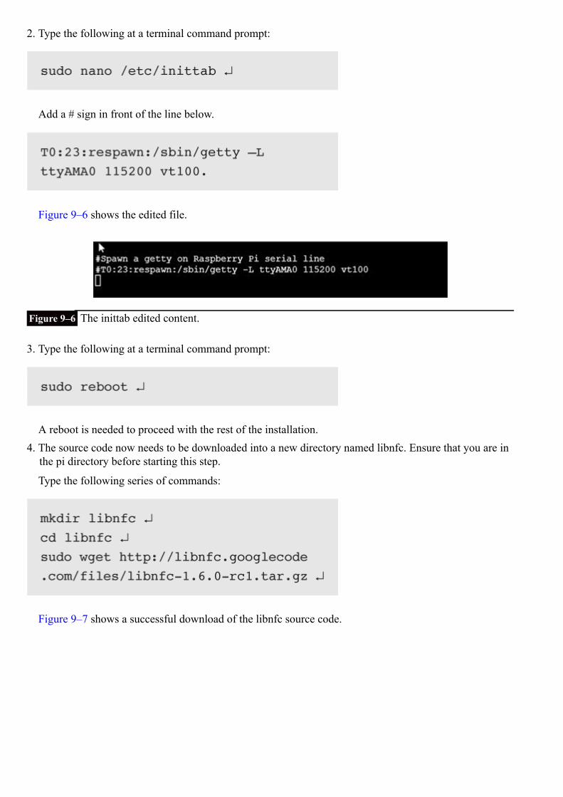
2. Type the following at a terminal command prompt:
Add a # sign in front of the line below.
Figure 9–6 shows the edited file.
Figure 9–6 The inittab edited content.
3. Type the following at a terminal command prompt:
A reboot is needed to proceed with the rest of the installation.4. The source code now needs to be downloaded into a new directory named libnfc. Ensure that you are in
the pi directory before starting this step.
Type the following series of commands:
Figure 9–7 shows a successful download of the libnfc source code.

Figure 9–7 The libnfc source code download.
5. The downloaded source needs to be “unzipped.” A new subdirectory named libnfc-1.6.0-rc1 will auto-matically be created in the libnfc directory after this action is completed.
Type the following at a terminal command prompt:
Figure 9–8 shows the end portion of the display after this extract operation has finished.
Figure 9–8 The libnfc source code extract operation.

6. One of the source code files must be slightly modified in order for libnfc to connect to the RasPithrough the ttyAMA logical device. Type the following at a terminal command prompt:
You need to add “ttyAMA” to the following line in the file:
Figure 9–9 shows the file content after the edit has been done.
Figure 9–9 The uart_posix.c source code edit.
CAUTION Ensure that you use double quotes around ttyAMA or the logical device will not be recog-nized. The strange fact is that the file will compile OK, but the device ttyAMA will neverbe recognized and the board will never connect. A frustrating experience to say the least.
7. libnfc must next be configured to operate with the RasPi and the breakout board. Type the following at aterminal command prompt:
Figure 9–10 shows the end results of the configure operation. Just confirm that the line
appears as the last line.

Figure 9–10 End of the configure operation.
8. The preparation for the actual build of the source code starts next. Type the following at a terminal com-mand prompt:
This preps all the source code, libraries, etc. for the actual build. Figure 9–11 shows the end of the prepstage.

Figure 9–11 The end of the build prep.
9. The actual build happens in this stage. I have included two screenshots showing the start and end of theprocess. This build will take about 30 minutes, so be patient. Type the following at a terminal commandprompt:
Figure 9–12 shows the start of the build.
Figure 9–12 The Build start.
Figure 9–13 shows the end of the build. There will now be a complete libnfc installation on the RasPiafter this screen appears.
Figure 9–13 The build end.
Hardware InstallationThe interface between the RasPi and the PN532 breakout board requires only four wires, as shown in theblock diagram in Fig. 9–14. The Pi Cobbler prototype tool is also used to ease this installation.

Figure 9–14 The RasPi and the PN532 interface.
I also connected an LED to pin 23 with a series-current-limiting resistor. The LED will provide a visualindication when a tag is detected, using the Python program. Figure 9–15 is a picture of the physical layoutof the hardware.
Figure 9–15 Project hardware layout.
Do not be concerned with the fact that 5 V is being connected to the PN532 board, while there are directconnections to the UART lines, TXD and RXD. The PN532 shifts the voltage such that only 3.3 V appearson the UART lines, thus protecting the RasPi from any overvoltage being applied to the GPIO pins.
Initial CheckoutThere is a very useful test program named nfc-poll, which is provided in the libnfc package and will test thehardware and software for proper operation. First, ensure that you are in this directory:
Then enter the following at the command line prompt:

Put a tag on or near the reader, and you should see something similar to the Fig. 9–16 screenshot.
Figure 9–16 The nfc-poll test program output.
Of course, your UID tag information will be different from what is shown in the figure, but everythingelse should be the same. Successful program execution means that you are now ready for the project pro-gram.
Project ProgramThe project program is designed to check for a predesignated tag ID and then turn on an LED if the tagis detected by the reader. This program provides the basic functionality of the NFC design and serves as atemplate to expand the application for additional uses, which will be described later.
The Python code listing is shown on page 123. This program named extract_data.py uses the nfc-pollprogram to capture the tag information and writes it to a text file named nfc_data.txt. This file is then readand parsed to extract the tag ID data. This ID data is then compared to a hard-coded tag ID to check if itmatches. A match will turn on the LED for 10 seconds as well as display the word “match” on the consolescreen. If the tag doesn’t match, the phrase “no match” appears on the console.
Run the program from the pi directory by entering the following at the command prompt:
The console display cursor will jump to a new line and wait for a tag to be placed near the reader. Oncethis is done, the display will show “match” or “no match,” and the LED will light for 10 seconds only on amatch condition.
This program is quite constrained in that it must have the desired tag ID hard coded before it is run. Butas previously stated, it is only a starter or template that you can use to greatly increase the flexibility andutility of the project. Suggested modifications and improvements are discussed in the next section.

Future ExpansionThe obvious expansion would be to have the RasPi signal an electronically controlled locking mechanismto unlock when an authorized tag is detected. In most cases, there will be more than one authorized tagholder who will need access to a protected area or building. This will require a list of authorized tag IDs tobe checked because each tag contains a unique ID. Python accommodates several ways to do this function.Tag IDs could even be placed in a database that the program could query. This is actually the way such anaccess function is accomplished in real-world situations that use commercial systems. Such systems are alsovery expensive.
extract_data.py
Another expansion might be to have the program send a preset e-mail when a specific tag is detected.The e-mail program shown in Chap. 8 could easily be incorporated into this project program. The e-mailwould be automatically created and sent when a tag is detected. I could envision a situation in which a childor perhaps a disabled person might need to send a non-urgent e-mail for help or assistance. Obviously, call-ing 911 (or the international equivalent) should be used in an emergency. All the person need do is to swipethe tag near the reader, and the e-mail will be sent. An LED should also light to confirm that the e-mail wassent.
Other applications that might use tag-initiated activities include home tasks, such as starting an irrigationsystem, pool cleaning, garage door opening/closing, home spa operations, and so on.
SummaryThis chapter began with an explanation of what NFC is and how it works. The two primary operationalmodes were shown.

The PN532 breakout board was discussed next, along with the rationale as to why it was selected forthis project.
This was followed by a brief overview of the NFC communication interchange, which illustrated that itwas a robust, TCP-like data flow between the RasPi and the PN532.
A comprehensive, nine-step procedure was detailed, showing how to install the open-source libnfc soft-ware package. This package is installed in the Wheezy Linux distribution run on the RasPi.
A relatively easy hardware install was covered along with a quick test program to prove that the PN532could detect a tag.
The project program was discussed next and then executed, causing a preset tag ID to be detected andan LED to be lit to show that the tag had been detected.
The chapter concluded with suggestions for further improvements, modifications, and expansions.

CHAPTER 10
1-Wire Weather Station
IntroductionAs the chapter’s name implies, I will be showing you how to build a weather station. This station will be quite basic,measuring only temperature, pressure, and humidity, but it may be easily expanded to measure other weather compon-ents, such as wind speed and rainfall. All the weather sensors are connected to the RasPi with a very clever interfaceknown as 1-Wire™, which makes it very easy to add additional components.
The RasPi runs on a software package named owfs, short for 1-Wire File System. This open-source software con-tains every function required to interface the RasPi with all the system components used in this project.
Weather Station DesignFigure 10–1 is a system block diagram that shows the components or modules involved in this project.
Figure 10–1 Weather station block diagram.
The system is a point-to-point interconnection, starting with the USB to 1-Wire adapter that is plugged into a porton a powered USB hub, which, in turn, is connected to one of the RasPi USB ports. I didn’t show the hub on the dia-gram because it should be considered as part of the basic RasPi configuration.
All the modules and the USB adapter are available in the United States from www.hobby-boards.com. Similarmodules are available from www.sheepwalkelectronics.co.uk for international readers. These items are listed in Table10–1.
Table 10–1 Listing of Weather Station Modules and Adapters
The first element shown connected to the RasPi in the system diagram is an adapter in the physical form of a USBdongle, as shown in Fig. 10–2. It has a USB connector at one end and a 1-Wire connector at the opposite side.

Figure 10–2 USB to 1-Wire dongle.
The 1-Wire socket shown in the figure is a standard RJ12, six-pin, telephone-style connector. A specialRJ12 to RJ45 cable is required to go from the dongle to the first 1-Wire module, which in this case, is thePower Injector Module. This special cable is shown in Fig. 10–3 and is typically provided when you pur-chase the 1-Wire-to-USB dongle.
Figure 10–3 RJ12 to RJ45 cable.
Most 1-Wire modules use the standard eight-pin RJ45 connection standard, which is exactly the sameas a regular Ethernet patch cable. In fact, I used normal Ethernet patch cables to interconnect all the 1-Wiremodules for this project.
CAUTION Be sure that you do not inadvertently use an Ethernet crossover cable because that willbreak the 1-Wire connection scheme. It will not harm the modules, but the data connectionwill not work.
The next element shown in the system diagram is the Power Injector Module, which is shown in Fig.10–4.

Figure 10–4 Power Injector Module.
A 15-V “wall wart” power supply (a box-shaped device that plugs into the AC electrical wall outlet andprovides DC power to various electronic devices) plugs into a socket mounted on the case top. There arealso two RJ45 connectors mounted on the sides of the case that are not visible. The cable from the USBdongle connects to the left socket, while the patch cord that goes to the next module connects to the rightsocket. The 15 V are sent out through the Ethernet cable and are also down regulated to 5 V for local use bya 78M05 regulator mounted on the internal PCB that is shown in Fig. 10–5.
Figure 10–5 Power Injector PCB.
It turns out that some 1-Wire modules do not require a separate power supply. This is discussed in thesection describing various ways to power a 1-Wire network. In this weather station project, the barometer,humidity, and packet sniffer modules do require the use of a power injector because their power consump-tion exceeds the 1-Wire standards for parasitic power supply operation, which will be discussed shortly.
The weather modules following the Power Injector Module do not have to be inserted in any particularorder. I will show you the Temperature Module next. Figure 10–6 shows the external case.
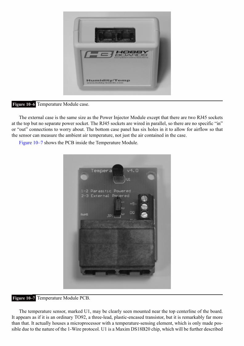
Figure 10–6 Temperature Module case.
The external case is the same size as the Power Injector Module except that there are two RJ45 socketsat the top but no separate power socket. The RJ45 sockets are wired in parallel, so there are no specific “in”or “out” connections to worry about. The bottom case panel has six holes in it to allow for airflow so thatthe sensor can measure the ambient air temperature, not just the air contained in the case.
Figure 10–7 shows the PCB inside the Temperature Module.
Figure 10–7 Temperature Module PCB.
The temperature sensor, marked U1, may be clearly seen mounted near the top centerline of the board.It appears as if it is an ordinary TO92, a three-lead, plastic-encased transistor, but it is remarkably far morethan that. It actually houses a microprocessor with a temperature-sensing element, which is only made pos-sible due to the nature of the 1-Wire protocol. U1 is a Maxim DS18B20 chip, which will be further described

later. You should also notice that a three-terminal strip, located at the midpoint of the right side, allows fora separate power supply to be attached and for the module’s digital output to be accessed via the terminalmarked DQ. We do not use this terminal strip, as all modules are interconnected via the RJ45 cables. It justallows for additional flexibility.
The Humidity Module will be described next. I am not showing an external case picture because it isidentical to that of the Temperature Module except for the Humidity designation on the case front. The in-ternal PCB, however, is considerably different, as you may see from Fig. 10–8.
Figure 10–8 Humidity Module PCB.
The humidity sensor, designated as U3 (not visible in Fig. 10–8), is located at the top of the board. It isa Honeywell model HIH-4021-001 sensor that produces an analog output based on the humidity it senses inthe ambient air. These analog sensor readings are sent to chip U1, which is a Maxim DS2438A. This chipis also incorporated into the Barometer Module and will be discussed in a following section. The externalterminal connection strip is also present and can be seen on the right-hand side of the board. This strip isnot used here, as I mentioned in the Temperature Module discussion.
The Barometer Module is the last sensor to be discussed. Again, no external case picture is needed, butthe PCB board is shown in Fig. 10–9.

Figure 10–9 Barometer Module PCB.
The pressure sensor, designated as U2, is located on the left side at the top of the board. It is a FreescaleSemiconductor model MPXA4115A sensor, which produces an analog output based on the ambient air pres-sure within the range of 28 to 32 inches of mercury. These readings are sent to chip U1, a Maxim DS2438A,the same chip that was used in the Humidity Module. The U1 chip is not visible in this figure because it issurface mounted to the backside of the board. The twice-mentioned terminal board is also visible. A poten-tiometer is located on the upper right side to precisely calibrate the module to a known air pressure.
I will discuss the Packet Sniffer Module in a later section. Next, I will discuss the 1-Wire protocol,which is the base technology for this project.
1-Wire ProtocolThe 1-Wire protocol is the registered trademark name given to a digital serial communications protocol byDallas Semiconductor, the company that first introduced it in the early 1990s. However, the trademark doesnot affect any software implementing the protocol. Dallas Semiconductor was merged with Maxim yearslater but still manufactures 1-Wire products along with many other components. This is the reason why1-Wire products have a DS prefix.
1-Wire uses a master/slave, multi-drop architecture with an open-drain connection with pull-ups to 5 V.This means that devices may be added or removed without any change to the hardware configuration beingspecified. All devices are discovered through software techniques. Also all 1-Wire devices have a unique64-bit identification number that is encoded in a ROM by the manufacturer.
The master and all slaves act as transceivers meaning that they can both transmit and receive, but not atthe same time. This mode of operation is known as half-duplex with data transmission being unidirectional.The master initiates all communication on the bus with the slaves responding only to commands sent bythe master. All data is sent by serial bits in a specific timed sequence. Bit timing is asynchronous with noexternal clock required, since all timing is based on the signal transitions from the master.
All communication flow between the master and slaves involves three activities, as shown in Fig. 10–10.

Figure 10–10 1-Wire communication flow.
1. Reset—In the first phase, the bus master must issue a reset command that synchronizes all elements onthe 1-Wire bus. All slaves must respond to the reset, or the bus will not function as desired.
2. Detect and Select—A specific slave device is next selected to receive commands from the master in thenext phase. This selection is a multipart process that is started by using a binary search algorithm to dis-cover all the slaves currently connected on the bus. Remember, all 1-Wire devices have a unique serialID permanently programmed into their onboard ROM. The search algorithm reads and records all theIDs and records these values in a dynamic table that is hosted in the master. The master can then use aspecific ID to send commands to a slave with that ID, while all other slaves ignore the command.
3. Receive and Perform Command—In the last phase, the master and selected slave engage in half-duplexcommunication in which the master issues commands and the slave responds as designed.
Maxim DS2438A ChipThe Maxim DS2438A chip is used in both the Barometer and Humidity Modules. It deserves a separatediscussion because it serves as a specialized controller between a module sensor and the 1-Wire bus. Thischip is formally designated as a Smart Battery Monitor; however, it is used in another role for the aforemen-tioned modules. Figure 10–11 is a block diagram illustrating the many functions implemented by this smallchip, which is only an eight-lead small-outline integrated circuit (SOIC).
Figure 10–11 DS2438A block diagram.

The chip contains an analog-to-digital converter (ADC) that converts the sensor’s analog signals intoequivalent digital signals that can be passed over the 1-Wire network.
The module’s unique 64-bit ID is also stored in a ROM contained in this chip. The ROM contains allthe programming code needed to respond to the master’s reset command as well as to the other commandsunique to the module.
The parasitic capacitor and blocking diode discussed below are also shown in Fig. 10–11.
Maxim DS18B20 ChipThis chip is called a Programmable Resolution 1-Wire Digital Thermometer by the manufacturer. Some keyspecifications are listed below:
Configurable from 9 to 12 bitsMeasures –55° to +125°CMeasures –10° to +85°C with a +/– 0.5°C accuracyHas its own 64 bit IDPowered from 3 to 5.5 V (may be parasitically powered)Converts 12 bits within 750 ms
Figure 10–12 shows the DS18B20 block diagram. There is an awful lot crammed into a TO92 case.
Figure 10–12 DS18B20 block diagram.
Powering the 1-Wire BusThere are three ways that the 1-Wire bus can be powered. These are:
1. External power supply2. Parasitic supply using a capacitor and diode3. Powering the data line using a strong pull-up metal–oxide–semiconductor field-effect transistor
(MOSFET)
The first way, using an external supply, is the one we used in this project by incorporating the PowerInjector Module. You were also shown how to connect a local power supply to a specific module using aterminal board located on the PCB. It should be noted that the Power Injector Module is wired to providepower to all bus devices, while a local power supply powers only the device to which it is wired.

The second way is called parasitic because the module power is obtained by charging a capacitor fromthe 1-Wire data line while it is idling at a 5-V level. Figure 10–13 shows the simple charging circuit.
Figure 10–13 Capacitor-based parasitic power supply.
The blocking diode shown in the figure prevents the charged capacitor from interfering with the voltagelevels on the data line. There are two disadvantages to using this scheme:
1. The increased capacitive load on the bus data line decreases the effective physical length of the bus line.2. The capacitor charge can supply only a very small current before being discharged.
The third way, using an active device such as a MOSFET, allows for power to be supplied to the dataline during idle time. It essentially improves the parasitic power supply performance because the mastercontrols the MOSFET to provide a strong pull up during idle time. This circuit is shown in Fig. 10–14.
Figure 10–14 Active pull-up power supply.
The active pull up provides for extended range and a much better current supply at the expense of re-quiring a dedicated microprocessor GPIO pin as well as additional programming for that GPIO pin.

1-Wire SnifferThe 1-Wire Sniffer is a diagnostic module that connects to the 1-Wire network and provides a real-timeview of the data flow. It has an RS-232 serial port that may be seen at the top of the PCB, as shown in Fig.10–15.
Figure 10–15 1-Wire Sniffer PCB.
The RS-232 serial connection can be attached to any computer running a terminal control program witha configuration of 8 data bits, 1 stop bit, no parity, and 115,200 baud. The particular sniffer board used inthis project is powered via the bus. I used an external laptop running the Tera Term program to displaythe network data. The RasPi could have been used; however, it was simpler and easier just to use anothercomputer for the monitoring and diagnostic functions. You will see some sample screenshots in the sectiondescribing the operating weather station.
The sniffer module is an exception to the unique ID protocol because it is not expected to operate as anormal slave device. All of the sniffers made by this manufacturer have the same ID of 0x01, which meansthat only one can be deployed into a given 1-Wire network. That’s usually not an issue because you wouldnever require more than one sniffer per network. The master can issue a limited number of commands tothis sniffer, including:
F—Puts Sniffer into firmware upgrade modeS—Puts Sniffer into the sniffer modeP—Pauses the SnifferH—Display help message
Set Up the Weather Station HardwareThe weather station modules should now be interconnected using Ethernet patch cables, and the USBdongle should be plugged into a powered USB hub. Plug the cable from the USB dongle into the PowerInjector Module. All the other modules are daisy-chained from the Power Injector Module. The 15 V wallwart power supply must also be plugged into the Power Injector Module. Figure 10–16 shows the wholesetup.

Figure 10–16 The 1-Wire weather station.
1-Wire File SystemThe software package that drives the whole 1-Wire network is named owfs, as mentioned in the introduc-tion. It is an open-source, comprehensiveset of applications that works seamlessly with the RasPi Wheezy distribution. The following are the instruc-tions on how to set up the RasPi to run owfs:
1. Update and upgrade the Wheezy distribution:
(this might take some time).2. Next download and install owfs:
3. Next, edit the owfs configuration file.
There are two changes to make. Refer to Fig. 10–17 to see these changes.

Figure 10–17 The owfs.conf file changes.
4. The last step should be to reboot the RasPi in order to put the configuration changes into effect:
Viewing the Weather DataThe real-time data from the modules may be viewed from the owfs server. Open a browser on another com-puter other than the RasPi, and go to the local RasPi IP address with port 2121 appended. In my case it was:
Figure 10–18 is a screenshot of the owfs server opening page, showing a directory name for each of themodules from Fig. 10–16.
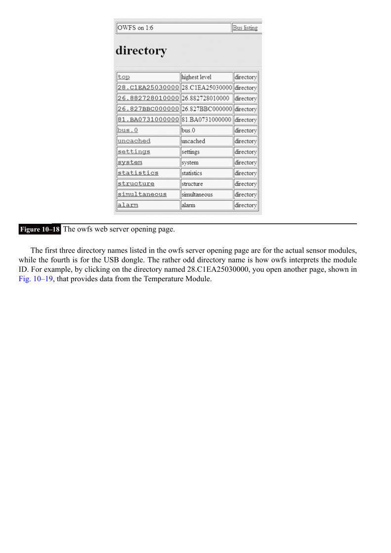
Figure 10–18 The owfs web server opening page.
The first three directory names listed in the owfs server opening page are for the actual sensor modules,while the fourth is for the USB dongle. The rather odd directory name is how owfs interprets the moduleID. For example, by clicking on the directory named 28.C1EA25030000, you open another page, shown inFig. 10–19, that provides data from the Temperature Module.

Figure 10–19 Temperature Module results.
A lot of information appears, but the key data is the temperature itself, which is shown at 20.8125 °C.You need to refer to the owfs user’s manual to determine what all the other data means except the temphighand templow entries, which are self-explanatory. Apparently, those readings are shown in degrees Fahren-heit due to the owfs default configuration setup.
Clicking on the directory named 26.882728010000 opens the Humidity Module page. Figure 10–20shows the data on this page.
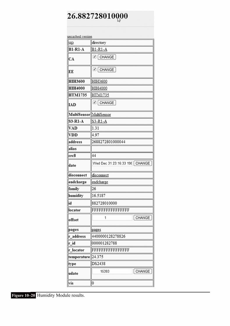
Figure 10–20 Humidity Module results.

Again, there is plenty of data shown as was the case with the Temperature Module results. The humidityreading is near the lower middle of the list and shows a value of 16.5187. I am certain that the sensor isnowhere near that accurate; however, the owfs software calculates a value based on the raw data sent backto it from the module.
The last module is the Barometer Module with its results shown by clicking on the directory named28.827BBC000000. Figure 10–21 shows the data on this page.
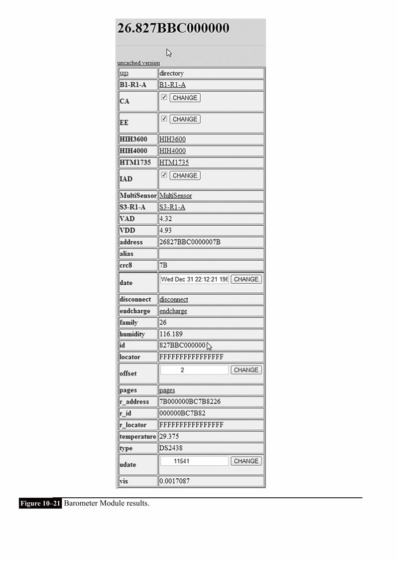
Figure 10–21 Barometer Module results.

However, there is a problem here. If you look closely at all the data in this figure, you will not find anybarometric pressure value. You must click on the directory entry named B1-R1_A to view another page withthe desired data. Figure 10–22 shows this page.
Figure 10–22 Barometric pressure value.
The pressure displayed is 1001.87 millibars. The actual pressure measured at a nearby airport was1014.6 millibars, so the Barometer Module was reading a bit low. The potentiometer mentioned in the mod-ule discussion needs to be adjusted to properly calibrate the barometric sensor.
Packet SniffingI connected the 1-Wire Sniffer Module to the network to test out the functionality. The sniffer was connectedto a 64-bit laptop by using a USB-to-serial-port adapter. The laptop was running the Windows 7 UltimateOS. I also used the Tera Term program that I previously discussed in Chap. 5 with a terminal configurationas listed in the above sniffer module discussion. Figure 10–20 Humidity Module results.
I also decided to test the remote login capability that required me to determine my home network’spublic IP address. The procedure detailed in Chap. 8 was used. I also set the home network router’s portforwarding to 2121 and pointed it to the RasPi’s local address. Figure 10–23 is a combined screenshot thatshows both the owfs opening page along with the Tera Term display of packet data that was created by thisaction.

Figure 10–23 Screenshot of an owfs initial page overlaid with Tera Term packet data.
The interpretation of the first line of data follows:First data packet = RP F0 28 C1 EA 25 03 00 00 C4
RP is short for presence pulse.
F0 is a one byte ROM command. This one returned the ROM module ID.
28 C1 EA 25 03 00 00 is the ROM ID sent back to the master.
C4 is a CRC check byte used for error checking.
The following three lines in the sniffer window performed the same action for the other three modulesin the 1-Wire network. Notice that they are displayed in precisely the same order as they are listed in theowfs directory web page.
I then clicked on the Temperature Module directory to see what the sniffer returned. Figure 10–24 is theresulting screenshot.

Figure 10–24 Screenshot after the Temperature Module directory was clicked.
As one might expect, there is obviously a lot more information being created so that owfs can populatethe Temperature Module’s report page (Fig. 10–19). You should notice that the module’s ROM ID is re-peated in each line of the sniffer display. This makes it quite easy to identify the specific module that istransmitting data over the 1-Wire network. I refer you to the owfs user’s manual if you desire to learn moreabout commands and returned data.
Future ExpansionAdding modules is very simple, and the owfs software will easily handle most existing 1-Wire weather mod-ules. You are really limited by your own resources, if you desire to add additional modules to the 1-Wirenetwork.
A useful module to add would be an anemometer to measure wind speed and a compass encoder to getwind direction. The only other module that could be added to fully populate this weather station is a raingauge.
SummaryThe chapter began with a review of the weather station design that is based upon using a series of separate,interconnected sensor modules, all using the 1-Wire network.
Next, the components and functions of each module used in the project were discussed.The 1-Wire protocol was then examined along with an integral controller chip, the DS2438A.Various ways the 1-Wire network could be powered were also reviewed and the pros and cons of each
approach were pointed out.Instructions on how to set up both the hardware and software were provided. The software package owfs
was also configured to provide Web-based weather reports. These reports were accessed both locally overthe home network and remotely over the Internet.
Finally, the Sniffer Module was discussed as a means of checking real-time data flowing over the 1-Wirenetwork. This is a very handy tool to have available for debugging and for program development.
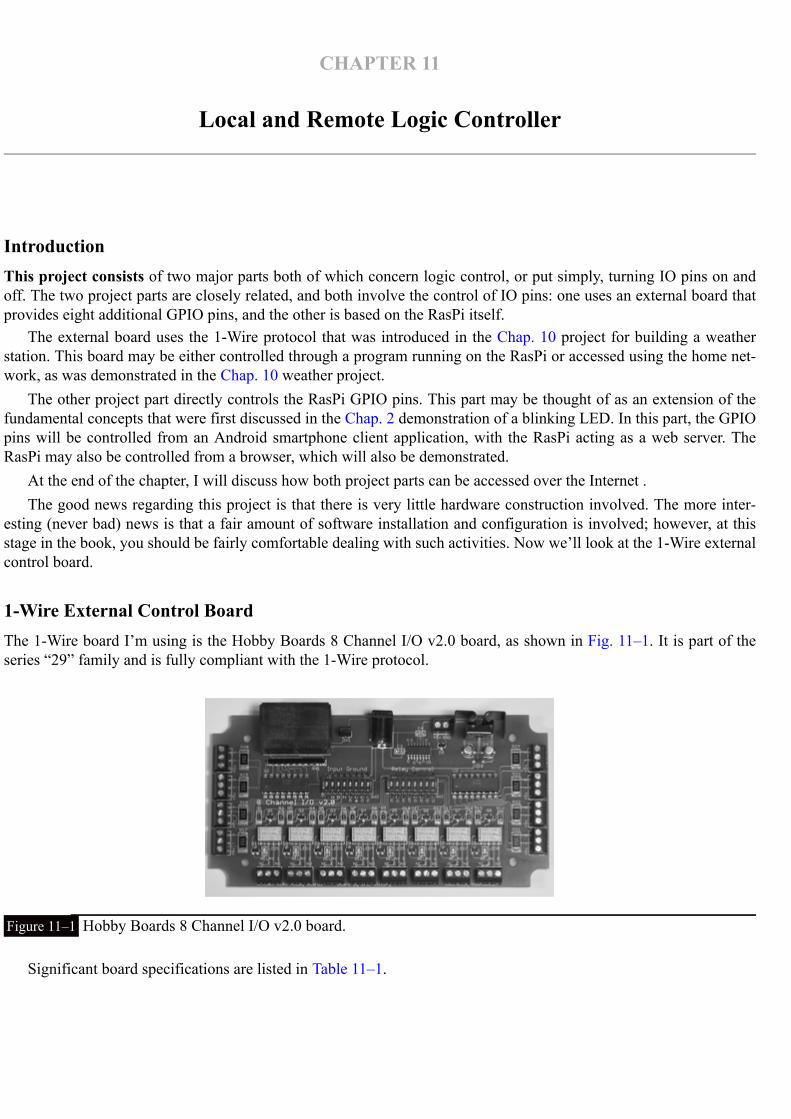
CHAPTER 11
Local and Remote Logic Controller
IntroductionThis project consists of two major parts both of which concern logic control, or put simply, turning IO pins on andoff. The two project parts are closely related, and both involve the control of IO pins: one uses an external board thatprovides eight additional GPIO pins, and the other is based on the RasPi itself.
The external board uses the 1-Wire protocol that was introduced in the Chap. 10 project for building a weatherstation. This board may be either controlled through a program running on the RasPi or accessed using the home net-work, as was demonstrated in the Chap. 10 weather project.
The other project part directly controls the RasPi GPIO pins. This part may be thought of as an extension of thefundamental concepts that were first discussed in the Chap. 2 demonstration of a blinking LED. In this part, the GPIOpins will be controlled from an Android smartphone client application, with the RasPi acting as a web server. TheRasPi may also be controlled from a browser, which will also be demonstrated.
At the end of the chapter, I will discuss how both project parts can be accessed over the Internet .The good news regarding this project is that there is very little hardware construction involved. The more inter-
esting (never bad) news is that a fair amount of software installation and configuration is involved; however, at thisstage in the book, you should be fairly comfortable dealing with such activities. Now we’ll look at the 1-Wire externalcontrol board.
1-Wire External Control BoardThe 1-Wire board I’m using is the Hobby Boards 8 Channel I/O v2.0 board, as shown in Fig. 11–1. It is part of theseries “29” family and is fully compliant with the 1-Wire protocol.
Figure 11–1 Hobby Boards 8 Channel I/O v2.0 board.
Significant board specifications are listed in Table 11–1.

Table 11–1 8 Channel I/O Board Specifications
An eight-position DIP switch labeled “Relay Control” is on the board. It can disable any of the relaysif you wish to do so. Another eight-position DIP switch labeled “Input Ground” is used in connection withthe input terminals. Inputs should be connected as follows:
1. Non-powered inputs—Connect one lead to the positive terminal marked “+.” The other lead is connec-ted to the powered screw terminal marked “+5v.” The corresponding “Input Ground” DIP switch shouldbe in the on (up) position, which is also the default position.
2. Powered inputs—Connect one lead to the positive terminal marked “+.” The other lead is connected tothe negative terminal marked “–.” The corresponding “Input Ground” DIP switch should be in the off(down) position. The input polarity is a “don’t care” situation because the input opto-isolators are bid-irectional, as can be seen in Fig. 11–2, which shows a portion of the board’s schematic. You can evenuse low-voltage AC to trigger the input.
Figure 11–2 8 Channel I/O board input schematic.
The full schematic along with the board’s user’s manual is available from www.hobby-boards.com.
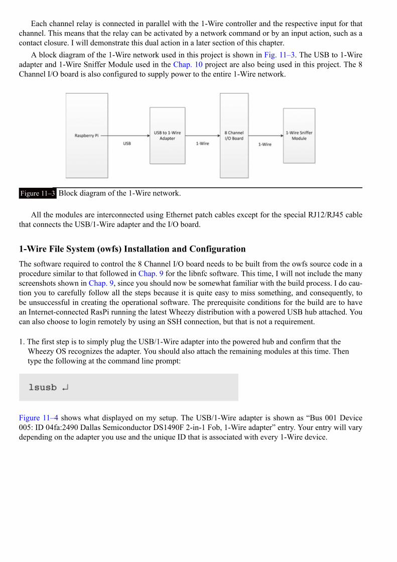
Each channel relay is connected in parallel with the 1-Wire controller and the respective input for thatchannel. This means that the relay can be activated by a network command or by an input action, such as acontact closure. I will demonstrate this dual action in a later section of this chapter.
A block diagram of the 1-Wire network used in this project is shown in Fig. 11–3. The USB to 1-Wireadapter and 1-Wire Sniffer Module used in the Chap. 10 project are also being used in this project. The 8Channel I/O board is also configured to supply power to the entire 1-Wire network.
Figure 11–3 Block diagram of the 1-Wire network.
All the modules are interconnected using Ethernet patch cables except for the special RJ12/RJ45 cablethat connects the USB/1-Wire adapter and the I/O board.
1-Wire File System (owfs) Installation and ConfigurationThe software required to control the 8 Channel I/O board needs to be built from the owfs source code in aprocedure similar to that followed in Chap. 9 for the libnfc software. This time, I will not include the manyscreenshots shown in Chap. 9, since you should now be somewhat familiar with the build process. I do cau-tion you to carefully follow all the steps because it is quite easy to miss something, and consequently, tobe unsuccessful in creating the operational software. The prerequisite conditions for the build are to havean Internet-connected RasPi running the latest Wheezy distribution with a powered USB hub attached. Youcan also choose to login remotely by using an SSH connection, but that is not a requirement.
1. The first step is to simply plug the USB/1-Wire adapter into the powered hub and confirm that theWheezy OS recognizes the adapter. You should also attach the remaining modules at this time. Thentype the following at the command line prompt:
Figure 11–4 shows what displayed on my setup. The USB/1-Wire adapter is shown as “Bus 001 Device005: ID 04fa:2490 Dallas Semiconductor DS1490F 2-in-1 Fob, 1-Wire adapter” entry. Your entry will varydepending on the adapter you use and the unique ID that is associated with every 1-Wire device.

Figure 11–4 lsusb display.
2. This step is a precautionary one to ensure that the Wheezy distribution is updated and upgraded. Type inthe following commands:
(This can take some time if there are many upgrades needed.)3. Next, the required build tools need to be installed. Type in the following command:
4. The source code has to be downloaded next. Type in the following command:
5. Extract the source code and subdirectory from the archive file by typing:
6. Change from the “pi” directory to the newly created “owfs-2.8p15” directory by typing:

7. The source code must now be “configured.” Type:
(This step takes about three minutes to complete.)8. The build happens next. Type:
(Be patient; this takes over 30 minutes to complete.)9. Finish the build process by typing:
(It takes about one minute.)
10. You now need to create a directory where the device files may be accessed. Type:
11. I found the next step useful as a way to ensure that the RasPi was in a good or consistent state. Type:
Login as you would normally, and you should be in the “pi” directory.
12. You now need to start the owfs filesystem and identify the mount point. Type the following:
NOTE This command should be done only once after the initial boot. If you try to remount the 1wiredirectory from the command line prompt after an initial mount operation, it typically resultsin a “Permission Denied” error. However, I did find that remounts were possible if used in aprogram statement. So-called “nonempty” warnings were created by the owfs file system.
Figure 11–5 is a screenshot showing the results of the mount operation. I then changed directories from“pi” to “1wire” by typing:

Figure 11–5 1-Wire owfs mount operation.
I did an “ls” to display the 1wire directory contents that identified the two normal 1-Wire deviceson the network (the Sniffer Module is non-conforming). The USB/1-Wire adapter belongs to the family of1-Wire devices beginning with the string “81.” That meant the remaining directory, starting with the familydesignator of “29” must be the 8 Channel I/O board.
I changed into that directory by typing:
The directory contents are displayed at the bottom of Fig. 11–4.I would like next to clarify an important aspect of how Linux treats hardware before proceeding much
further into this part of the project.
Linux, Hardware, and FUSEUnix and its descendent Linux “treat everything as files” according to the old mantra. This phrase encom-passes all things, including hard drive files, serial ports, thumb drives, etc. You can read and write to ahardware device, if it accommodates such actions, in exactly the same way as you can read and write to anordinary file, provided the permissions are properly set. The view that everything can be handled as a filecertainly simplifies how programs handle data to and from hardware devices.
There is also another particular file category that doesn’t appear until the OS is running. In this categoryare virtual files that are dynamically created upon demand and are often-times stored in the /sys directory.The Filesystem in Userspace (FUSE) application supports the owfs application by creating and storing thesevirtual files in FUSE registered directories. The “/mnt/1wire directory” is the designated site in which tostore all the virtual files created for the 1-Wire network currently operating.
You can prove to yourself that the virtual files exist. Simply reboot and do a “ls” on the /mnt/1wiredirectory. Nothing will show. Next type in the mount command from step 12 and redo the “ls” command.Then you should see a directory data display like the one shown in Fig. 11–4 for the 1wire directory. owfsapplications and FUSE are integral to each other; the system wouldn’t work without either of them.
Another very useful feature is that the 1wire directory will automatically be updated as modules areremoved from and/or added to the 1-Wire network. Figure 11–6 shows what happened before and after Iplugged a Temperature Module (family “28”) into the 1-Wire network. Note, that I did not have to type anycommands; the addition was automatically detected.
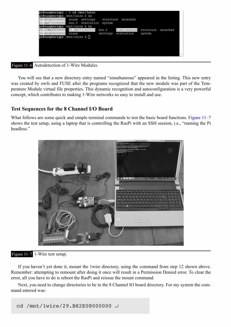
Figure 11–6 Autodetection of 1-Wire Modules.
You will see that a new directory entry named “simultaneous” appeared in the listing. This new entrywas created by owfs and FUSE after the programs recognized that the new module was part of the Tem-perature Module virtual file properties. This dynamic recognition and autoconfiguration is a very powerfulconcept, which contributes to making 1-Wire networks so easy to install and use.
Test Sequences for the 8 Channel I/O BoardWhat follows are some quick and simple terminal commands to test the basic board functions. Figure 11–7shows the test setup, using a laptop that is controlling the RasPi with an SSH session, i.e., “running the Piheadless.”
Figure 11–7 1-Wire test setup.
If you haven’t yet done it, mount the 1wire directory, using the command from step 12 shown above.Remember: attempting to remount after doing it once will result in a Permission Denied error. To clear theerror, all you have to do is reboot the RasPi and reissue the mount command.
Next, you need to change directories to be in the 8 Channel IO board directory. For my system the com-mand entered was:
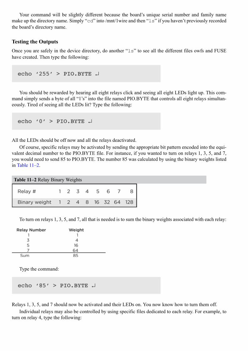
Your command will be slightly different because the board’s unique serial number and family namemake up the directory name. Simply “cd” into /mnt/1wire and then “ls” if you haven’t previously recordedthe board’s directory name.
Testing the OutputsOnce you are safely in the device directory, do another “ls” to see all the different files owfs and FUSEhave created. Then type the following:
You should be rewarded by hearing all eight relays click and seeing all eight LEDs light up. This com-mand simply sends a byte of all “1’s” into the file named PIO.BYTE that controls all eight relays simultan-eously. Tired of seeing all the LEDs lit? Type the following:
All the LEDs should be off now and all the relays deactivated.Of course, specific relays may be activated by sending the appropriate bit pattern encoded into the equi-
valent decimal number to the PIO.BYTE file. For instance, if you wanted to turn on relays 1, 3, 5, and 7,you would need to send 85 to PIO.BYTE. The number 85 was calculated by using the binary weights listedin Table 11–2.
Table 11–2 Relay Binary Weights
To turn on relays 1, 3, 5, and 7, all that is needed is to sum the binary weights associated with each relay:
Type the command:
Relays 1, 3, 5, and 7 should now be activated and their LEDs on. You now know how to turn them off.Individual relays may also be controlled by using specific files dedicated to each relay. For example, to
turn on relay 4, type the following:

Relay 4 turns on. The individual relay file names start at 0 not 1. This is not true for the board relays,which are numbered 1 through 8. This difference is a small detail that can nonetheless cause some confu-sion.
Testing the Inputs
Sensing inputs is very similar to setting outputs except for one major difference. A ‘1’ is used to indicatethat no input is present or detected. All the relays must also be disabled, by turning all the switches on theRelay Control DIP switch to the off (down) position. This configuration is required because an IO line can-not be both an input and an output at the same time.
Next, ensure that nothing is connected to any input and then type the following:
You should see the value 255 displayed just before the command line prompt, just like the circled num-ber in Fig. 11–8.
Figure 11–8 Result for the sensed.BYTE command.
The value 255 is the decimal equivalent of all 1’s for 8 bits or 1 byte. To test this concept out a bitfurther, connect a jumper wire between the screw terminals marked “+5v” and “+” on input terminal 8.What would you expect to see displayed after you type in “cat sensed.BYTE”? A moment’s thought mighthelp you realize that the binary value of the bit for the number 8 input (relay binary weight of 128) wouldbe 0; hence the value should be 255–128 or 127. Go ahead and type the command:
You should be rewarded to see the value 127, just as you expected. It’s not really too hard after all!Now it is time to try out a Python program to exercise the 8-Channel I/O board. You first need to enable
all the relays by putting all the Relay Control DIP switches to the on (up) position.
Python Test ProgramThis program cycles relays 2 and 4 every 10 seconds forever unless stopped by a keyboard interrupt that isdone by pressing the ‘control’ and ‘c’ keys simultaneously (^C). I also included a statement to autoload the1wire directory so that the command shown in step 12 does not have to be explicitly entered. The file objectstatement will have to be modified to suit your installation, since it has the unique address for my 8-ChannelI/O Board hard coded into it. This file is named ow_eight. py and is available from the book’s companionwebsite, www.mhprofessional.com/raspi.

Type the following at the command line prompt:
Relays 2 and 4 should click, and the associated LEDs should blink on for 5 seconds then off for 5seconds. This program should be used as a starting point from which you can develop your own controlprogram to match your desired application.
Remember that a given I/O channel may be used either as an input or an output but not as both simul-taneously. This is precisely the situation with the RasPi GPIO pins where a particular pin may be set as anoutput for one part of an application and then used as an input in another part. The major difference betweenthe RasPi and the I/O board is that a physical switch must be set on the I/O board, while a GPIO pin maybe reset by a program statement with the RasPi. It is just a bit more limiting to use the I/O board as com-pared to the pure programming situation allowed with the RasPi. However, having eight channels availableprovides a good deal of flexibility.
Caution The relay contacts are rated for a maximum of 250 mA at 250 V AC, which equates to an ap-proximate 60-watt load. Do not attempt to switch more than a 60-watt load using theselight duty relays, and under NO circumstances should you try to control a line voltage ACmotor. If you want to control a heavy AC-inductive load, use the relay to control a motorcontroller that is rated for the AC load. This is a safe practice, and one that should be ad-hered to at all times.
ow_eight.py
Sniffer MonitoringI was interested in monitoring the 1-Wire network activity while the ow_eight.py program was running.Figure 11–9 is a screenshot from my laptop running the Tera Term program that I discussed in Chap. 10.The laptop was connected to the Sniffer Module, using a USB-to-serial adapter and cable.

Figure 11–9 Sniffer packet activity.
The figure shows the repeated activity of switching the selected channels on and off, which was expec-ted. What was not expected is the periodic polling of the 1-Wire network taking place every two minutes.That may be deduced by observing the shorter packets interspersed among the repeated control packets ini-tiated by the ow_eight program. The two-minute interval was calculated by knowing that each repeat packetwas issued every 10 seconds.
While not critical for program development, the sniffer is a very handy tool that helps you understandwhat is occurring within the 1-Wire network.
Android Remote ControlIn this section I will show you how to control the RasPi GPIO pins by using an application running on anAndroid smartphone. The smartphone application is named DrGPIO and is available as donationware fromthe Google’s Play Store app. Donationware, as the name implies, means that you may donate to the authorif you use it and find it useful. You must also download the web server portion named WebIOPi. Follow thisprocedure to download and install the server:
1. Type the following at a command line prompt:
2. Next, extract the source code:

3. Change directories to the newly created one:
4. Install and set up the software using a preset script:
NOTE I had the initial setup fail on me. I did the following to resolve the issue:
Repeat step 4 above.
Figure 11–10 shows the end result of the setup command.

Figure 11–10 Setup command end result.
5. The HTTP web server is started using Python as follows:
The 8000 is optional because it is the default. I like to include it, since it is a reminder of the actual portnumber. Figure 11–11 shows the console display for the web server starting.
Figure 11–11 Starting the WebIOPi HTTP web server.
The user name is “webiopi” and password is “raspberry” if you are asked for them by the application.The service may be stopped by either a keyboard interrupt (^C) or closing the terminal window in which itwas started. You may also start and stop the web server as a service using these commands:

The web server can even be started during the boot process by entering the following command:
Testing the Web server with the Android AppI set up the RasPi with a Pi Cobbler prototype tool to drive three LEDs, as shown in the Fig. 11–12 diagram.
Figure 11–12 Test setup diagram.
You will need to determine the RasPi’s local IP address in order to connect the Android application tothe RasPi web server. In my case, it was 192.168.1.21. All I needed to do was type that address into thephone, as shown in Fig. 11–13.
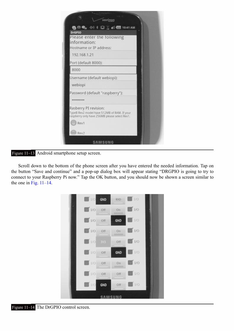
Figure 11–13 Android smartphone setup screen.
Scroll down to the bottom of the phone screen after you have entered the needed information. Tap onthe button “Save and continue” and a pop-up dialog box will appear stating “DRGPIO is going to try toconnect to your Raspberry Pi now.” Tap the OK button, and you should now be shown a screen similar tothe one in Fig. 11–14.
Figure 11–14 The DrGPIO control screen.

Figure 11–14 is a graphical representation of the RasPi 26-pin GPIO connector. The check boxes shownimmediately to the side of each pin box allow you to select whether the pin is to act as an input or output.The check mark will be highlighted if it is set as an input. We need pins 18, 23, and 25 unchecked so thatthey are functioning as outputs. To output a 1, simply tap the pin box. The bar in the pin box will fill in,and the label will change from “off” to “on”. The pin will now be outputting a 1, or high level (3.3 V DC).Figure 11–15 is a picture of the test setup with the three LEDs turned on.
Figure 11–15 Functioning output test setup.
Testing the inputs is very easy. Just select the pins that you want to be used for inputs by ensuring thatthe check marks are highlighted and then connect those pins to the 3.3 V DC power supply. Figure 11–16shows the phone screen with pin 18 set as an input and also connected to the 3.3 V DC supply. Pins 23 and24 were left as outputs.
Figure 11–16 A phone input test screen.
Sharp-eyed readers may have spotted two additional pins that are set up as inputs and appear as if theyare “on,” yet are not connected to the 3.3 V DC. These two pins are called floating inputs, meaning they areunconnected and can receive stray voltage that can trigger a false reading of a high input. I deliberately leftthis condition in the figure to show you that you can unwittingly create a short circuit to ground by resettinga floating input GPIO pin to output without removing the ground wire.

Testing the Web Server with a BrowserThe HTTP web server may also be run from any local computer’s browser. Simply type in the RasPi’s localIP address with port 8000 as a suffix. In my case this was:
Figure 11–17 is a display of the resulting web page. All the configurable GPIO pins were set as outputsfor this screenshot. All the functionality discussed in the Android section is available using a browser. Usinga browser in this manner makes configuring GPIO pins very easy without the need to create any Pythoncode to test basic I/O for a hardware project. I highly recommend that you consider using this approach tospeed up your project development.
Figure 11–17 WebIOPi web page using a browser.
Internet AccessYou will need your router’s public IP address to be able to remotely control the RasPi’s GPIO pins.Determining this address has already been discussed several times in previous chapters. You will also needto enable port forwarding on the router so that any browser or smartphone using port 8000 will automatic-ally be forwarded to the RasPi’s local IP address. I had no problem in setting this up on the Android smart-phone and on a remote computer’s browser.
The only issue is to remember which GPIO pins are connected to which devices. It would definitely bea problem if you wanted to turn on your home’s front outdoor light but accidently started the lawn irrigationsystem. The WebIOPi GUI may be customized to use different widgets and labels to suit your particularapplication. It does require a knowledge of HTML and Javascript to accomplish this, which is well beyondthis book’s scope. I refer you to the WebIOPi documentation located at https://code.google.com/p/webiopi/.There is a lot of information at this site, including a discussion of Representational State Transfer (REST),which is the underlying technology that powers the web server. It is well worth your time to look at thecontent and gain an appreciation of what is happening “behind the curtains”.

Remote Access to the 8 Channel I/O BoardThe first step is to ensure that the owfs HTTP server is running. Type this at the command-line prompt:
Next, open a browser on a computer that is part of the local network and go to the RasPi’s local IP ad-dress with port 2121 appended. In my case, this was:
Figure 11–18 is a screenshot of the opening web page. This should look somewhat familiar, as I de-scribed a similar operation in Chap. 10, when opening a web page to access the weather station data.
Figure 11–18 Initial web page for 8 Channel I/O board.
I then clicked on the 8-Channel I/O Board directory named 29.B82E08000000, which revealed the webpage shown in Fig. 11–19. I apologize for the fine print here, as the figure has been resized to make it fit ona page in this book. It is definitely readable in a browser window.


Figure 11–19 Directory 29.B82E08000000 web page.
One neat feature is that now you can enter relay control numbers directly into the box labeled PIO.BYTE and click on the Change button. I entered 255, clicked on the Change button, and instantly heardeight relays click and saw all eight LEDs light up. You should also review Fig. 11–5 to understand why thisweb page is so big. All the files listed in the device directory are also displayed on this web page. All thedata operations discussed in the section entitled “Testing the Inputs” are available through this web page.Figure 11–20 shows the result of entering 255 in the PIO.BYTE box.

Figure 11–20 Testing the PIO.BYTE data entry.
I did notice that starting the owfs web server stopped the owfs file system application and unmountedthe files in the 1wire directory. I do not believe this should be a real problem because you will likely beusing either one or the other but not both simultaneously.
Internet access will be done in exactly the same way as discussed above except the forwarding port is2121.
SummaryThe 1-Wire 8 Channel I/O board was first examined with a detailed review of the board’s key specifications.This board provides an expanded number of GPIO pins beyond the RasPi’s seven.
Next, a 12-step build and configuration process that created an owfs development environment support-ing the I/O board was carefully explained.
I then took a brief digression to explore Linux, FUSE and owfs. This explanation should help you un-derstand how owfs functions.
Testing the I/O board inputs and outputs came next. I used only commands entered at the terminalprompt to exercise the board functions.
A short Python program, ow_eight.py, that controlled the I/O board through a series of output com-mands was demonstrated. A brief view of the Sniffer Module output was also shown. The ow_eight.py pro-gram should serve as an example of how to create more complex programs suited to unique applications.
I next showed you how to control the RasPi’s GPIO pins by using an Android smartphone applicationnamed DrGPIO along with the WebIOPi web server installed on the RasPi. I also demonstrated how youcould operate the same functions with the same WebIOPi web server by using a regular browser.
The chapter concluded with a demonstration on how to control the I/O board using the HTTP owfs webserver from a browser.

CHAPTER 12
Robotic Car: Part 1
IntroductionThis chapter is one of two that will show you how to build a RasPi controlled robotic car. I’ve spread the project overtwo chapters because of the build complexity and the software involved. The elements covered here in Part 1 includethe mechanical construction and the hardware and software that control the drive system.
Developing the robotic car has been a very enjoyable experience, and the project has attracted a lot of interestamong folks who are curious about what the Raspberry Pi is and how it can be used. There is nothing like a roboticcar to stir up interest in this great little board. Now on to building the car!
OverviewI thought it would be a good idea to show you some pictures of the car all built and ready to run. Figures 12–1 to 12-3show the final project with the optional thin-film transistor (TFT) display mounted.
Figure 12–1 Raspberry Pi robotic car (front view).

Figure 12–2 Raspberry Pi robotic car (left side view).
Figure 12–3 Raspberry Pi robotic car (right side view).
And yes, that is the Wheezy Linux desktop being displayed in Fig. 12–1. I use a wireless keyboard andmouse to interact with the RasPi just as I would normally when sitting at my desk. This is truly a portablecomputer on wheels.
The car, however, will not be controlled by keyboard or mouse commands but will instead be handledby a Wii remote control device (Wiimote), as shown in Fig. 12–4.

Figure 12–4 Wiimote.
The Wiimote uses Bluetooth, a wireless technology for data transfer over short distances, to communic-ate with the RasPi, which will be discussed in Chap. 13.
Chassis and Drive MotorsThe car uses a simple tripod configuration of two powered wheels and a third one as a free rolling ball toprovide stability and a very tight turning radius. All the chassis, drive, and power supply components arelisted in Table 12–1 and are available from www.parallax.com
Table 12–1 Chassis, Drive, and Power Supply Components
A servo control board is also required for this project. It is the 16-Channel 12-bit Pulse Width Modula-tion (PWM) /Servo Driver I2C Interface board available from Adafruit Industries, part number 815.
The Boe Bot chassis is made of 1.5 mm aluminum and is shown in Fig. 12–5.

Figure 12–5 Car chassis.
A complete drawing showing all the dimensions is available on the Parallax website for readers who areable and willing to make their own chassis. Just use the part number to look it up.
The continuous rotation servos provide the driving force for the wheels. Figure 12–6 shows a servo, andFig. 12–7 shows a wheel kit. Each wheel is attached to the drive servo with a 0.25-inch screw that is alsoprovided with each servo.
Figure 12–6 Continuous rotation servo.
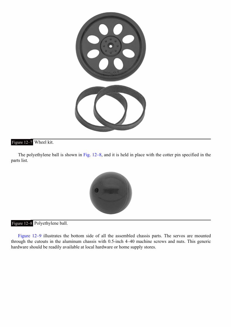
Figure 12–7 Wheel kit.
The polyethylene ball is shown in Fig. 12–8, and it is held in place with the cotter pin specified in theparts list.
Figure 12–8 Polyethylene ball.
Figure 12–9 illustrates the bottom side of all the assembled chassis parts. The servos are mountedthrough the cutouts in the aluminum chassis with 0.5-inch 4–40 machine screws and nuts. This generichardware should be readily available at local hardware or home supply stores.
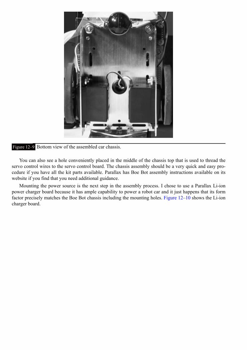
Figure 12–9 Bottom view of the assembled car chassis.
You can also see a hole conveniently placed in the middle of the chassis top that is used to thread theservo control wires to the servo control board. The chassis assembly should be a very quick and easy pro-cedure if you have all the kit parts available. Parallax has Boe Bot assembly instructions available on itswebsite if you find that you need additional guidance.
Mounting the power source is the next step in the assembly process. I chose to use a Parallax Li-ionpower charger board because it has ample capability to power a robot car and it just happens that its formfactor precisely matches the Boe Bot chassis including the mounting holes. Figure 12–10 shows the Li-ioncharger board.

Figure 12–10 Li-ion charger board.
This board uses two high capacity Li-ion cells rated at 3.7 V DC and 2600 mAh. One cell is shown inFig. 12–11. These cells conform to the 18650 form factor, which is a bit like an AA battery on steroids. Eachcell also contains a protection circuit to help prevent overcharging, which could lead to a serious situationif the cell was left unprotected. Nonetheless, these cells should be charged only with an appropriate chargerspecifically designed for them, which is the main reason why I incorporated the complete charger into thecar.
Figure 12–11 Li-ion cell.
NOTE The U.S. Postal Service will no longer ship items that contain lithium batteries to internationaldestinations, including APO and FPO addresses.
The charger board and all the other boards, including the RasPi, are mounted in a stacked “sandwich” ar-rangement. Please note that you will need to assemble and disassemble the stack several times as you buildthe car. This is unavoidable because you will have to custom fit the parts to the various mounting boards.Figure 12–12 is a Sketchup (3D modeling software once owned by Google but now owned by Trimble)representation of the beginning of the stack with the charger board mounted on four 0.25-inch OD nylonspacers.

Figure 12–12 Charger board Sketchup mounting diagram.
Four 1-inch nylon spacers are mounted on top of the board to provide sufficient room between the top ofthe charger board and the bottom of the Lexan mounting board. Figure 12–13 shows a portion of the actualmounted charger board so that you will gain an understanding of this arrangement.
Figure 12–13 The charger board mounting.
I used a 2-mm 4- × 4.5-inch Lexan board as a mounting platform to support the RasPi and the servo con-trol board. Figure 12–14 shows this board along with the charger board and the nylon spacers. The wholestack is held together by four 2.25-inch-long 6–32 machine screws that go through the Lexan board, hollowspacers, and the Li-ion charger board. I used a 6–32 tap to prethread the four matching holes on the BoeBot chassis to make the installation a bit easier. You can choose to do this or to simply use a 6–32 nut andwasher to lock down the screw. I believe you will need to slightly enlarge the chassis holes for clearance ifyou use screws and nuts.

Figure 12–14 Lexan and charger boards mounting diagram.
I would also recommend using the charger board as a drill template for the Lexan mounting board. Justensure that the Lexan board is mounted to have the 4-inch dimension between the wheels and the one edgeflush with the charger board, as shown in Fig. 12–14. It is important to ensure that the optional monitorsupport can be installed without interference.
Next, disassemble the Lexan board to mount the RasPi and servo control board. I used two 0.75-inch4–40 screws and nuts along with two 0.5-inch nylon spacers to mount the RasPi to the Lexan board. Usethe two mounting holes on the RasPi as drill guides for locating the holes in the Lexan board. Ensure thatthe RasPi board edge lines up with the Lexan board edge, as shown in Fig. 12–15. The servo control boardis mounted as shown in the diagram except that there are four mounting holes for that board. In addition, Iused nylon washers to space the servo board from the Lexan board. The mounting holes are very tight, soyou will need four very tiny machine screws and nuts.
Figure 12–15 RasPi and servo boards mounted.
Another Lexan mounting board is needed to support the solderless breadboard used for the Pi Cobblerand other items that can be seen in Figs. 12–2 and 12-3. This additional Lexan board is 3.5 × 4 inches andis mounted at the back of the car directly to the chassis, as shown in Fig. 12–16. You will need to notchout the board to provide clearance for two spacers supporting the charger board. I drew the cutouts on theboard’s Lexan protective paper and used a jig saw to make them. Also, mark three holes to be drilled in theLexan board, using the chassis holes as a guide. These three holes are obvious when you fit the board to thechassis. I used three 0.5-inch 4–40 machine screws and nuts to hold this board to the chassis.

Figure 12–16 Lexan board supporting the solderless breadboard.
The solderless breadboard mounts to the Lexan board with an adhesive backing. You should carefullyalign the breadboard to the Lexan plate before pressing it on. It is just about impossible to remove the bread-board once it is attached.
The remaining mechanical piece is the Lexan support plate for the portable monitor, if you should sochoose to install it. It is a fairly simple piece to install with the only tricky part being cutting clearance holesfor the RasPi USB ports and the additional LiPo battery that is used to power the monitor. Figure 12–17 is adimensioned sketch of the Lexan support that I used. Your support piece will likely vary a little from mine,since your RasPi placement may also vary from my installation.
Figure 12–17 Lexan monitor support piece.
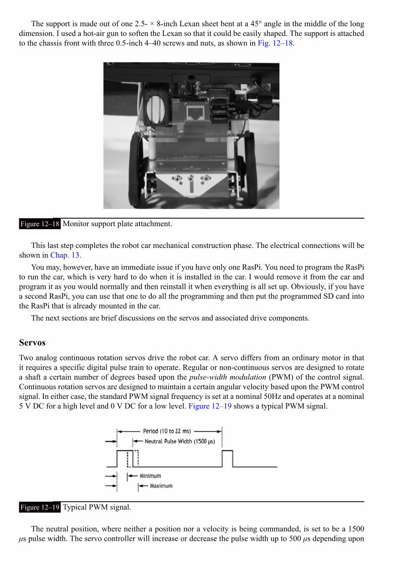
The support is made out of one 2.5- × 8-inch Lexan sheet bent at a 45° angle in the middle of the longdimension. I used a hot-air gun to soften the Lexan so that it could be easily shaped. The support is attachedto the chassis front with three 0.5-inch 4–40 screws and nuts, as shown in Fig. 12–18.
Figure 12–18 Monitor support plate attachment.
This last step completes the robot car mechanical construction phase. The electrical connections will beshown in Chap. 13.
You may, however, have an immediate issue if you have only one RasPi. You need to program the RasPito run the car, which is very hard to do when it is installed in the car. I would remove it from the car andprogram it as you would normally and then reinstall it when everything is all set up. Obviously, if you havea second RasPi, you can use that one to do all the programming and then put the programmed SD card intothe RasPi that is already mounted in the car.
The next sections are brief discussions on the servos and associated drive components.
ServosTwo analog continuous rotation servos drive the robot car. A servo differs from an ordinary motor in thatit requires a specific digital pulse train to operate. Regular or non-continuous servos are designed to rotatea shaft a certain number of degrees based upon the pulse-width modulation (PWM) of the control signal.Continuous rotation servos are designed to maintain a certain angular velocity based upon the PWM controlsignal. In either case, the standard PWM signal frequency is set at a nominal 50Hz and operates at a nominal5 V DC for a high level and 0 V DC for a low level. Figure 12–19 shows a typical PWM signal.
Figure 12–19 Typical PWM signal.
The neutral position, where neither a position nor a velocity is being commanded, is set to be a 1500μs pulse width. The servo controller will increase or decrease the pulse width up to 500 μs depending upon

the new desired position or velocity. The servo motor contains an electronic circuit that converts the PWMpulse train to the appropriate internal motor control signals that move the servo to the commanded positionor angular velocity.
Table 12–2 shows some of the specifications for the Parallax servos used in this robot car.
Table 12–2 Servo Specifications
I2C and the Servo ControllerA servo controller board is required for this project because the RasPi only has one channel that can outputPWM signals and the car needs two, one for each motor. I used the 16-channel, 12-bit PWM/Servo DriverI2C Interface Board available from Adafruit Industries. It is a bit of overkill for this application, but it isflawless in operation and very easy to set up.
I2C is another one of the serial protocols that was first introduced in Chap. 1. The servo control boarduses I2C to communicate with the RasPi. However, the RasPi must first be configured to operate with theI2C protocol, which is not built into the Wheezy distribution (as of the date of this writing). It is part ofthe Occidentalis v.2, if you choose to use that version, and is not very hard to setup Wheezy with the I2Cprotocol.
At the command line prompt, enter the following:
Add the next two lines to the end of the file.
Reboot the RasPi for the changes to take effect.
Enter the following commands after booting the RasPi:

(Be patient, this could take a while.)
These commands ensure that the Wheezy distribution is current with all the latest changes. Next, enter:
These commands load some useful applications that, among other things, allow you to check the addressof attached I2C modules. The i2c-tools package contains the i2cdetect application that will display all theI2C devices connected on the bus. Using it will confirm that the servo controller is being recognized by theRasPi.
The python-smbus package contains all the software needed to access I2C devices from Python. Thislibrary installation is critical to ensure that the robot control program works.
The next step may not be required. It depends upon the Wheezy distribution that you are running. Checkif there is a file name /etc/modprobe.d/raspi_blacklist.conf installed. You do nothing if it doesn’t exist; oth-erwise comment out these lines:
Enter the command below to edit the file, and put a “#” symbol in front of the lines shown above:
I2C Initial TestI would defer testing the I2C bus if you have only one RasPi and it is already installed in the car. However,if you are using a second RasPi for development, you might want to do the following test, using the tem-porary setup shown in Fig. 12–20, I2C test diagram.
Figure 12–20 Temporary I2C test diagram.
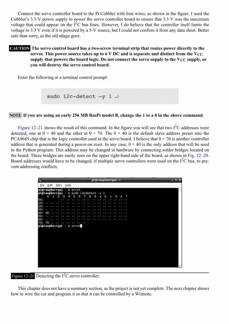
Connect the servo controller board to the Pi Cobbler with four wires, as shown in the figure. I used theCobbler’s 3.3-V power supply to power the servo controller board to ensure that 3.3 V was the maximumvoltage that could appear on the I2C bus lines. However, I do believe that the controller itself limits thevoltage to 3.3 V even if it is powered by a 5-V source, but I could not confirm it from any data sheet. Bettersafe than sorry, as the old adage goes.
CAUTION The servo control board has a two-screw terminal strip that routes power directly to theservos. This power source takes up to 6 V DC and is separate and distinct from the VCCsupply that powers the board logic. Do not connect the servo supply to the VCC supply, oryou will destroy the servo control board.
Enter the following at a terminal control prompt:
NOTE If you are using an early 256 MB RasPi model B, change the 1 to a 0 in the above command.
Figure 12–21 shows the result of this command. In the figure you will see that two I2C addresses weredetected, one at 0 × 40 and the other at 0 × 70. The 0 × 40 is the default slave address preset into thePCA9685 chip that is the logic controller used in the servo board. I believe that 0 × 70 is another controlleraddress that is generated during a power-on reset. In any case, 0 × 40 is the only address that will be usedin the Python program. This address may be changed in hardware by connecting solder bridges located onthe board. These bridges are easily seen on the upper right-hand side of the board, as shown in Fig. 12–20.Board addresses would have to be changed, if multiple servo controllers were used on the I2C bus, to pre-vent addressing conflicts.
Figure 12–21 Detecting the I2C servo controller.
This chapter does not have a summary section, as the project is not yet complete. The next chapter showshow to wire the car and program it so that it can be controlled by a Wiimote.
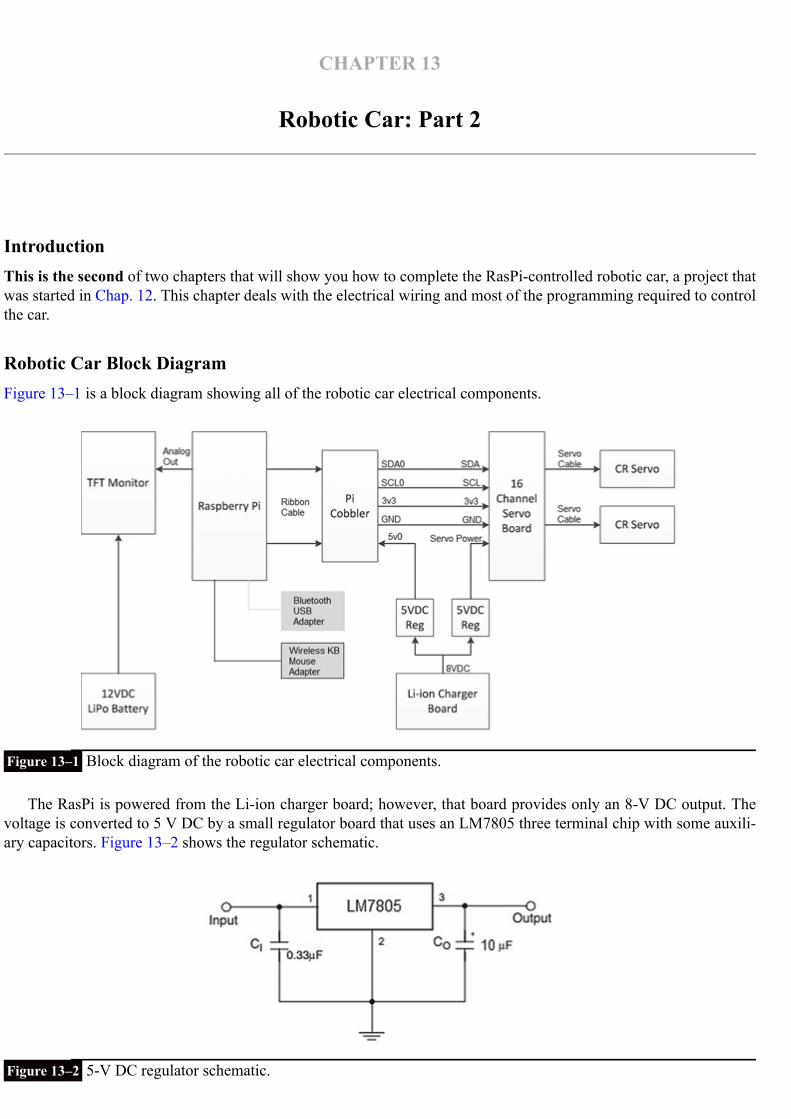
CHAPTER 13
Robotic Car: Part 2
IntroductionThis is the second of two chapters that will show you how to complete the RasPi-controlled robotic car, a project thatwas started in Chap. 12. This chapter deals with the electrical wiring and most of the programming required to controlthe car.
Robotic Car Block DiagramFigure 13–1 is a block diagram showing all of the robotic car electrical components.
Figure 13–1 Block diagram of the robotic car electrical components.
The RasPi is powered from the Li-ion charger board; however, that board provides only an 8-V DC output. Thevoltage is converted to 5 V DC by a small regulator board that uses an LM7805 three terminal chip with some auxili-ary capacitors. Figure 13–2 shows the regulator schematic.
Figure 13–2 5-V DC regulator schematic.

The 5-V output is connected to the Pi Cobbler’s 5-V pin 0. Technically, this arrangement is known as backfeeding because the 5-V 0 pin is normally an output, not an input. However, it makes no difference electric-ally if you supply or take off power from a parallel-connected power bus. By following this approach, youavoid having to hack up a micro USB connector and cable through which the RasPi is normally powered.
Shown on the block diagram is another 5-V DC regulator that provides power to the servo motor inputon the 16-channel servo control board (now simply referred to as the servo board). You might wonder whyI did this instead of paralleling the output already connected to the RasPi. The answer is that I wanted toavoid the situation in which a brief high-current demand from the servo motors would cause the regulatorvoltage output to drop below the minimally acceptable voltage for the RasPi, thus causing it to stop running.
The logic on the servo board is fed from the Pi Cobbler’s 3-V pin 3 for reasons already stated in Chap.12.
The TFT monitor requires 270 mA at 12 V DC to operate. This requirement necessitated that an addi-tional lithium-ion polymer (Li-Po) battery be added for the sole purpose of powering the monitor. The Li-Pobattery is normally used in a radio-controlled aircraft application where it can supply fairly high current forshort time bursts. However, it fits this situation quite well, being able to power the monitor for about eighthours, given its 2200-mA/h rating. Figure 13–3 shows this battery.
Figure 13–3 The Li-Po battery for the TFT monitor.
CAUTION The Li-Po battery must be recharged only with an approved charger designed for it.Under no circumstances should you use an automotive 12-volt charger with this battery.Bad things, such as a fire, will happen!
You may also have noticed a Velcro™ strip attached to the underside of the battery. I used this strip as aconvenient way to mount the battery and to allow it to be quickly removed for a recharge.
There are two Bluetooth micro USB adapters plugged into the RasPi’s USB slots. One is for theWiimote, and the other is for the wireless keyboard and mouse unit that I use with the car. Figure 13–4shows this Logitech model K400r keyboard and mouse combination. I have found it to be extremely reli-able and very moderately priced.
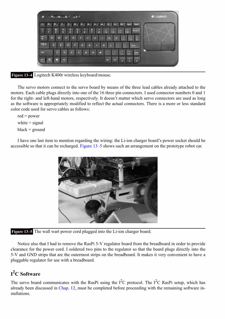
Figure 13–4 Logitech K400r wireless keyboard/mouse.
The servo motors connect to the servo board by means of the three lead cables already attached to themotors. Each cable plugs directly into one of the 16 three pin connectors. I used connector numbers 0 and 1for the right- and left-hand motors, respectively. It doesn’t matter which servo connectors are used as longas the software is appropriately modified to reflect the actual connectors. There is a more or less standardcolor code used for servo cables as follows:
red = powerwhite = signalblack = ground
I have one last item to mention regarding the wiring: the Li-ion charger board’s power socket should beaccessible so that it can be recharged. Figure 13–5 shows such an arrangement on the prototype robot car.
Figure 13–5 The wall wart power cord plugged into the Li-ion charger board.
Notice also that I had to remove the RasPi 5-V regulator board from the breadboard in order to provideclearance for the power cord. I soldered two pins to the regulator so that the board plugs directly into the5-V and GND strips that are the outermost strips on the breadboard. It makes it very convenient to have apluggable regulator for use with a breadboard.
I2C SoftwareThe servo board communicates with the RasPi using the I2C protocol. The I2C RasPi setup, which hasalready been discussed in Chap. 12, must be completed before proceeding with the remaining software in-stallations.
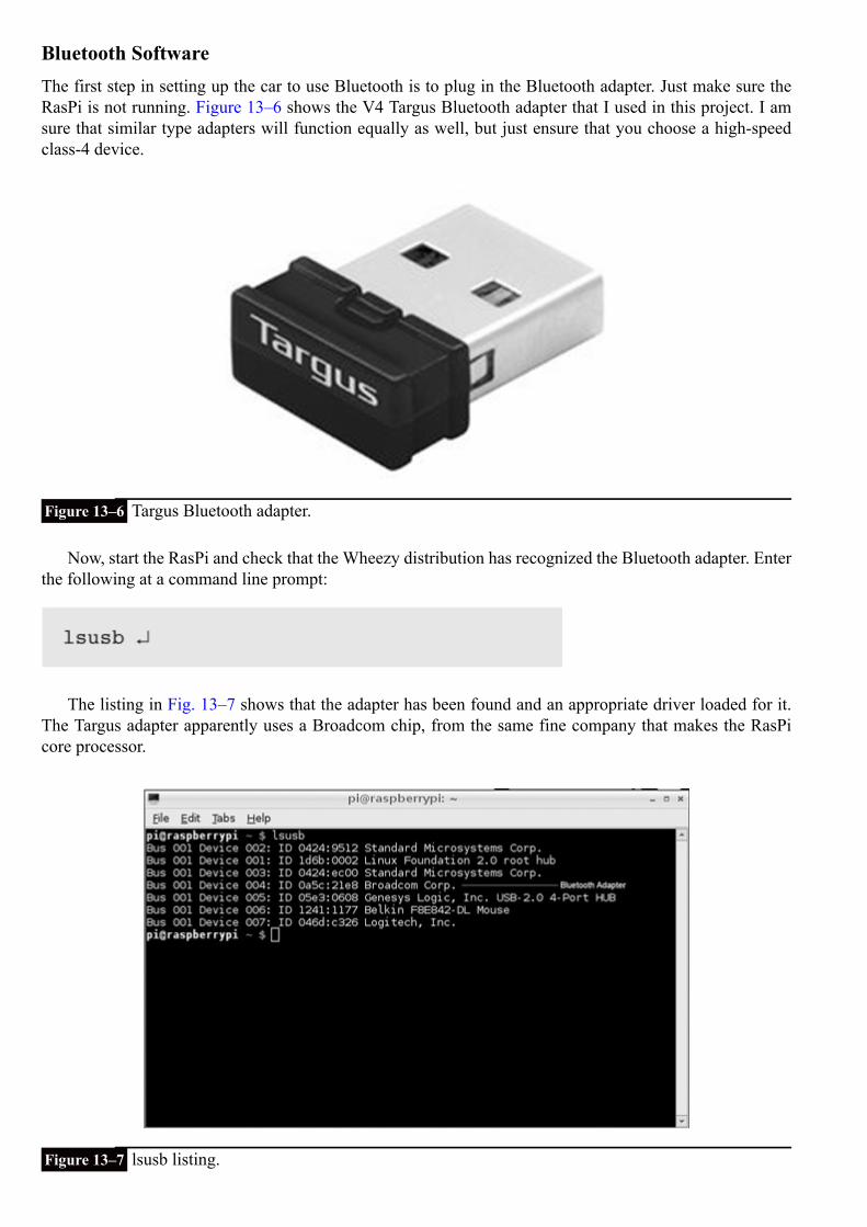
Bluetooth SoftwareThe first step in setting up the car to use Bluetooth is to plug in the Bluetooth adapter. Just make sure theRasPi is not running. Figure 13–6 shows the V4 Targus Bluetooth adapter that I used in this project. I amsure that similar type adapters will function equally as well, but just ensure that you choose a high-speedclass-4 device.
Figure 13–6 Targus Bluetooth adapter.
Now, start the RasPi and check that the Wheezy distribution has recognized the Bluetooth adapter. Enterthe following at a command line prompt:
The listing in Fig. 13–7 shows that the adapter has been found and an appropriate driver loaded for it.The Targus adapter apparently uses a Broadcom chip, from the same fine company that makes the RasPicore processor.
Figure 13–7 lsusb listing.

You next need to download and install the bluetooth software package. Enter the following at a com-mand line prompt:
(Be patient, this takes a while.)Enter the following to check if the Bluetooth service is running:
Figure 13–8 shows the status for an up-and-running service.
Figure 13–8 Bluetooth status.
If the status shows that it is not running, enter this command:
Reenter the above status command to confirm that the service is now running.Enter the following command to check on the adapter’s address:
Figure 13–9 shows the resulting screen display of the address of the Bluetooth adapter. The address isnot really needed, but it does check that the hcitool application was loaded with the Bluetooth package.
Figure 13–9 Bluetooth adapter address.
The stage is now set to start scanning for Bluetooth-enabled devices. Gather up your Wiimote and ensurethat it has fresh batteries installed. Enter the following command to start the scan:

You will see “Scanning …” displayed on the console screen. Simultaneously press the 1 and 2 buttonson the Wiimote to put it into the discovery mode. Don’t fret if it takes several tries to discover the remote.The screen will show a time-out if the RasPi doesn’t discover the remote within 5 to 10 seconds. Just tryagain. Eventually you will be rewarded with a display, as shown in Fig. 13–10.
Figure 13–10 Wiimote discovered.
Notice that all Bluetooth-enabled devices in the immediate vicinity are discovered. In Fig. 13–10, boththe Wiimote (Nintendo RVL-CNT-01) and an HP wireless printer were discovered. Don’t be concerned withconflicting Bluetooth devices because the protocol is quite capable of keeping track of which device needsto be addressed by an application.
Another software package is needed to enable a Python program to interface to a Bluetooth device. Thispackage is named cwiid and is downloaded and installed by entering:
This package contains all the necessary applications that allow the Wiimote to interface with a user-cre-ated Python program. I would also like to extend my thanks to Brian Hensley (www.brianhensley.net) forhis fine tutorial on using the Wiimote with the RasPi. It was invaluable in helping me to create the followingprograms.
However, before discussing an actual program, I need to show you how the Wiimote buttons are set withregard to state values, which are those numbers sent to the RasPi, indicating their corresponding buttonshave been pushed. Figure 13–11 is a Wiimote with all the corresponding state values superimposed on theimage.

Figure 13–11 Wiimote with state values.
For instance, if the forward button of the four-way switch is pressed, a value of 2048 will be transmittedvia the Bluetooth connection to the RasPi. Likewise, if the “–” button is pressed, a value of 16 is sent. Thevalues are also cumulative in case of combination button presses. For example, simultaneously pressing the1 button and the home button will cause a value of 130 to be sent: the sum of the home button value of 128and the 1 button value of 2. The application becomes a matter of decoding the values received and figuringout what actions to take based upon those values.
I created a simple test program named Wiimote_Test.py that establishes a Bluetooth connection betweenthe car and the Wiimote. The four-way switch on the Wiimote is then used to send different values, depend-ing upon which switch is pressed. Enter the following to run this program:
Figure 13–12 shows the result obtained by first establishing a connection and then pressing all fourswitches.

Figure 13–12 Wiimote_Test.py program results.
The Python code for Wiimote_Test.py is available from the book’s website, www.mhprofessional.com/raspi, and is also listed below:
Wiimote_Test.py
The expression “wm = cwiid.Wiimote()” is all that it takes to instantiate an object that logicallyrepresents the Wiimote. The object is then placed in the proper state to report its state value by the programline “wm.rpt_mode = cwiid.RPT_BTN.” From then on, all that needs to be done to retrieve the statevalue is to use the expression “wm.state[‘buttons’].”
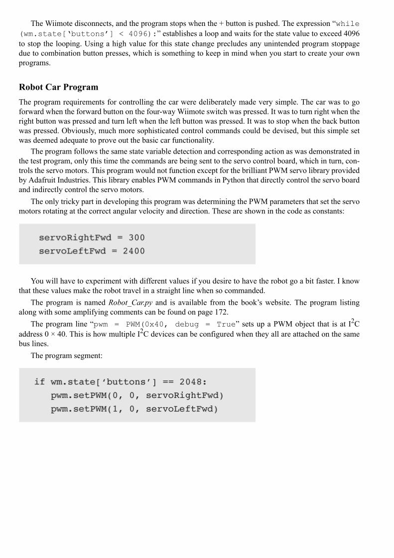
The Wiimote disconnects, and the program stops when the + button is pushed. The expression “while(wm.state[‘buttons’] < 4096):” establishes a loop and waits for the state value to exceed 4096to stop the looping. Using a high value for this state change precludes any unintended program stoppagedue to combination button presses, which is something to keep in mind when you start to create your ownprograms.
Robot Car ProgramThe program requirements for controlling the car were deliberately made very simple. The car was to goforward when the forward button on the four-way Wiimote switch was pressed. It was to turn right when theright button was pressed and turn left when the left button was pressed. It was to stop when the back buttonwas pressed. Obviously, much more sophisticated control commands could be devised, but this simple setwas deemed adequate to prove out the basic car functionality.
The program follows the same state variable detection and corresponding action as was demonstrated inthe test program, only this time the commands are being sent to the servo control board, which in turn, con-trols the servo motors. This program would not function except for the brilliant PWM servo library providedby Adafruit Industries. This library enables PWM commands in Python that directly control the servo boardand indirectly control the servo motors.
The only tricky part in developing this program was determining the PWM parameters that set the servomotors rotating at the correct angular velocity and direction. These are shown in the code as constants:
You will have to experiment with different values if you desire to have the robot go a bit faster. I knowthat these values make the robot travel in a straight line when so commanded.
The program is named Robot_Car.py and is available from the book’s website. The program listingalong with some amplifying comments can be found on page 172.
The program line “pwm = PWM(0x40, debug = True” sets up a PWM object that is at I2Caddress 0 × 40. This is how multiple I2C devices can be configured when they all are attached on the samebus lines.
The program segment:

Robot_Car.py
drives the car forward when the forward button is pressed. You just need to press the back button to stopthis motion. The same holds true for turning right or left.
Operating the Robotic CarThe car is essentially a peripheral for the RasPi, which means that you must start the computer as you wouldnormally do and simply enter the command to run the Robot_Car.py program as shown below:
You would then simultaneously press the 1 and 2 buttons on the Wiimote to connect to the RasPi viaBluetooth. Next, you would operate the car by using the four-way switch on the Wiimote to control the dir-ection of the car. That’s it. Press the “+” button to disconnect and stop the Bluetooth session.
Future ExpansionsThe following would be interesting and exciting modifications to this project to expand its usefulness andhopefully the learning experience:
Add a 5-V DC powered USB hub to the existing two USB ports that are both used. Adding a Wi-Fi ad-apter would provide a wireless networking capability and Internet access.Add a video camera, such as the GoPro Hero3. This unit has Wi-Fi connectivity, and is capable of beingremotely controlled by either its own remote control accessory or an Android smartphone or tablet run-ning the GoPro app. The remote control and Android app both have a real-time video preview function.Add an ultrasonic sensor that is capable of detecting objects in the forward path of the car. The Pythonprogram can easily be modified to handle sensor inputs and modify the path accordingly.Add an IR sensor to detect IR beams to redirect the car, basically creating an invisible fence or barrier.Add a GPS sensor to map the path of the car, assuming it travels more than a few meters. The UltimateGPS receiver discussed in an earlier chapter would be an ideal unit to install on the car. The path takencould be recorded in the RasPi SD card and later sent to Google Earth for display in that application.Add swarm or hive behavior if you happen to have an additional car or know someone with one. TheRasPi can easily handle the computing challenge that it takes to enable this type of collective behavior.The cars should be able to talk with one another using their installed adapters.Add an IR light and an IR sensitive camera to allow the car to maneuver in total darkness. This would bea very interesting and informative task, since rescue robots need to have this capability.
As you might imagine, many more items could be added to this list. It really is only limited by yourimagination. The robot car built in this project is only a start to bigger and much better projects.
SummaryThis project commenced with an overview of the car’s final form. Next came specific build instructions forthe chassis as well as for the “sandwich” construction that holds the various boards that make up the car.
A discussion followed regarding the servo drive motors and the associated PWM control signals. Thenwe looked at the procedure for setting up the RasPi to run the I2C protocol that is necessary to communicatewith the 16-channel servo control board.
Some preliminary testing was next shown that proved the I2C interface functioned as expected.A complete block diagram was shown to assist in connecting all the component boards and modules that
make up the car.After that step came a detailed procedure for setting up Bluetooth to run on the RasPi. A companion
software package named cwiid was downloaded and installed to enable a Python program to control a Wiiremote control (Wiimote).
A simple Python program was shown that allowed a user to control the car using a Wiimote. The carcan go forward, turn right or left, and stop.
The project finished with many suggestions for future car expansions and modifications.

CHAPTER 14
Radon Detector
IntroductionThis project could save your life. How’s that for an attention grabber! Radon, as most people know is a radioactivegas that can be present in homes and that often goes undetected. This project couples a Geiger counter with the RasPito measure and display the level of radioactivity in the monitored space. I will present plenty of background informa-tion so that you may learn precisely what radon is, how it is created, at what levels it is acceptable, and at what levelsyou should take some action.
The Geiger counter used in this project was built from the Velleman kit number K2645 and is shown in Fig. 14–1.This popular Geiger counter kit has been previously incorporated into other microcontroller projects, including onesusing the Arduino or the Parallax Basic Stamp.
Figure 14–1 Velleman K2645 Geiger-Muller counter.
Radioactivity and RadonRadioactivity is the process in which an unstable atom loses energy by emitting particles or rays of ionizing radiation.These particles and rays consist of:
Alpha particles—Helium nucleusBeta particles—High-energy, high-speed electrons or positrons with a neutrinoGamma rays—Highly energetic rays
The term ionizing radiation relates to the upset or damage a radioactive decay particle or ray can do to a livingcell. The alpha particle does the least damage because the epidermal skin layer stops it. A beta particle is a bit morepenetrating, but it can be stopped by various items, including a layer of cardboard, a sheet of polyethylene plastic,aluminum foil, moderate to heavy clothing, etc. The most damaging is the gamma ray, which can penetrate deep intothe human body. Gamma sources are normally shielded with lead, steel, concrete, etc.
The source of most natural radioactivity is uranium ore. It is the most abundant, naturally occurring radioactiveelement found in nature. The prime element found in uranium ore is 238U where the 238 is the atomic weight, i.e.,the number of protons and neutrons located in the nucleus. An associated key measure that will be mentioned in thisdiscussion is half-life or the length of time it takes for a specific radioactive element to lose half of its activity level.

For 238U, the half-life is 4.5 billion years. Most other radioactive materials have a much shorter half-life,including radon, which has a half-life of 3.8 days.
Radon is a colorless, odorless gas that is one of the many products of 238U radioactive decay. Radon’selemental symbol with atomic weight is 222Rn. It is also one of the densest gases known. The real problemthat radon poses is that it also decays and transmutes into what are known as daughters: solid particles thatstick to surfaces such as lung tissue.
Radon gas can and often does accumulate in confined spaces, such as basements and attics. It also occursnaturally in springs, both hot and cold. High levels of radon when inhaled over a period of time can lead tothe formation of lung cancer. According to the U.S. EPA, radon is the number one cause of lung cancer innon-smokers.
Radon, being in the 238U natural decay chain, is found wherever natural uranium ore is found. Often,238U is found in granite and shale deposits. I guess I am a bit unfortunate as I happen to live in New Hamp-shire, otherwise known as the Granite State. However, I have measured my home basement for radon andhave not detected any activity. Nonetheless, there is a radon vent pipe installed in the house that vents anyentrapped radon gas up and out through the roof.
Measuring RadioactivityThe International System of Units (SI) unit for measuring radioactivity is the becquerel, abbreviated as Bq.One Bq is a very tiny amount of activity. Another common unit is the curie, abbreviated as Ci. One Ci ismany orders of magnitude greater than one Bq. The exact relation is:
1 Ci = 3.7 × 10¹⁰ Bq
While the Bq and Ci are great for measuring radioactivity, the real question is, how much activity isdangerous to humans. Table 14–1 is a comparative listing showing radon activity levels and places wherethese levels might be encountered.
Table 14–1 Radon Radioactivity Levels
DoseAbsorbed dose, also known as total ionizing dose (TID), is a measure of the energy deposited in or affectinga medium by energetic or ionizing radiation. It is measured in joules per kilogram and represented in SIunits by the gray (Gy). The legacy unit is the rad.
Absorbed dose (now simply referred to as dose) is a complex measurement, because it depends on boththe level of activity of the ionizing radiation and the absorbing medium, which in most cases, is human tis-sue.
In the United States, a commonly applied measure of dose is the roentgen-equivalent-man or rem. It isa complex, computed, and weighted average of dose representing the stochastic biological effects of ioniz-ing radiation, which is one primary risk factor in cancer formation. The sievert (Sv) is the rem’s equivalentinternational SI unit. The conversion factor is 100 rem = 1 Sv, or in more realistic units, 100 μrem = 1 μSv.
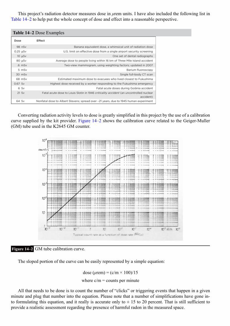
This project’s radiation detector measures dose in μrem units. I have also included the following list inTable 14–2 to help put the whole concept of dose and effect into a reasonable perspective.
Table 14–2 Dose Examples
Converting radiation activity levels to dose is greatly simplified in this project by the use of a calibrationcurve supplied by the kit provider. Figure 14–2 shows the calibration curve related to the Geiger-Muller(GM) tube used in the K2645 GM counter.
Figure 14–2 GM tube calibration curve.
The sloped portion of the curve can be easily represented by a simple equation:
dose (μrem) = (c/m × 100)/15
where c/m = counts per minute
All that needs to be done is to count the number of “clicks” or triggering events that happen in a givenminute and plug that number into the equation. Please note that a number of simplifications have gone in-to formulating this equation, and it really is accurate only to ± 15 to 20 percent. That is still sufficient toprovide a realistic assessment regarding the presence of harmful radon in the measured space.

K2645 Geiger-Muller CounterA brief discussion of how the GM counter functions will help provide a good basis for understanding how itwas interfaced to the RasPi. The essence of the GM counter is the detector tube, which is the approximately3-cm tube that may be seen in the upper left-hand corner of Fig. 14–1. It is a small metal cylinder typicallyfilled with argon gas, along with a wire conductor supported lengthwise in the middle of the cylinder. Thewire has an approximate 600 V DC potential on it. When a charged particle or energetic wave enters thetube, the gas breaks down or ionizes and forms a brief electrical short circuit between the inner wire andthe outer metal cylinder. This causes a momentary current flow that is detected and results in the click fromthe counter. These clicks are counted for the dose level measurement. Figure 14–3 is the schematic for theK2645 GM counter.
Figure 14–3 K2645 GM counter schematic.
There are four functional areas in the schematic:
1. A square wave oscillator that is connected to the transformer TRAF 01 primary.2. A voltage multiplier array that uses diodes and capacitors, and is connected to the TRAF 01 secondary
winding. This array creates the 600 V DC.3. The GM tube.4. A monostable oscillator that detects the momentary current pulses due to the radiation and activates a
piezo electric buzzer for the audio click.
The output from the board IC labeled N6 is used as an input to the RasPi interface, which is discussednext.
GM Counter/RasPi InterfaceThe interface has two requirements:
1. To transform the click signals to pulses that may be counted2. To count the pulses for preset intervals and output the resulting digital count to the RasPi
The block diagram/schematic for the interface is shown in Fig. 14–4.

Figure 14–4 GM Counter/RasPi interface block diagram/schematic.
Table 14–3 is a parts list for the interface circuit.
Table 14–3 GM Counter/RasPi Interface Parts List
The voltage output from the GM counter is reduced by 50 percent and connected to the input of theCD4040 chip. Counter output bits 0 to 6 are, in turn, connected to an 8-channel level shifter chip that con-verts the 5-V DC counter voltages to the 3.3-V DC level, which is compatible with the RasPi GPIO inputsignal lines. A single GPIO output from the RasPi is connected through the level shifter chip to the counterreset line, thus allowing the ripple counter to be reset for the start of a new count period.
Figure 14–5 shows the bottom side of the GM counter with a white wire connected to the N6 output anda green wire connected to a ground point.
Figure 14–5 Output wire connections on the GM counter.

Initial Test ConfigurationThe interface circuit was first set up on a solderless breadboard with the GM counter connected, as shownin Fig. 14–6.
Figure 14–6 Initial test configuration.
I also purchased a sample of uranium ore that was used to test the project. The ore sample is rather in-nocuous, although it was certified to have a 6000 cpm—with most of that activity due to alpha radiation.The certification paper is shown in Fig. 14–7, in case anyone is interested in purchasing a sample. It is alsoperfectly legal to ship this type of ore sample because its activity levels fall well below any regulations gov-erning radioactive material transport.

Figure 14–7 Uranium ore sample certification.
All eight of the RasPi GPIO pins were used in the interface. Seven were set up as inputs to read thecount from the 12-bit ripple counter, and the eighth was set as an output to reset the counter.
Below you will find the Python code, available on the book’s website www.mhprofessional.com/raspi,from a program named geiger.py that was used to test the initial configuration:
Figure 14–8 is a screenshot of the program output captured from my laptop that was on an SSH con-nection to the RasPi. The ore sample was put in essentially direct contact with the GM tube in an effort toobtain the highest readings possible.

geiger.py
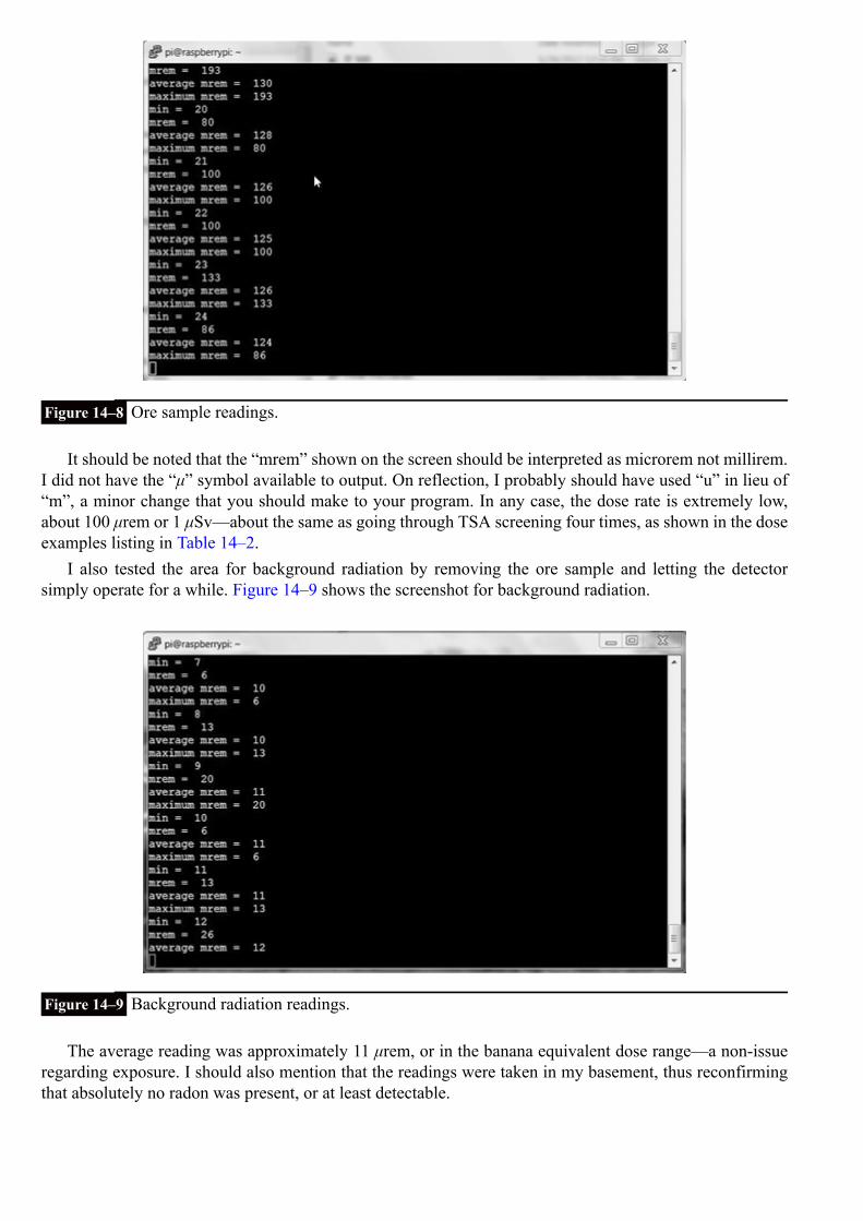
Figure 14–8 Ore sample readings.
It should be noted that the “mrem” shown on the screen should be interpreted as microrem not millirem.I did not have the “μ” symbol available to output. On reflection, I probably should have used “u” in lieu of“m”, a minor change that you should make to your program. In any case, the dose rate is extremely low,about 100 μrem or 1 μSv—about the same as going through TSA screening four times, as shown in the doseexamples listing in Table 14–2.
I also tested the area for background radiation by removing the ore sample and letting the detectorsimply operate for a while. Figure 14–9 shows the screenshot for background radiation.
Figure 14–9 Background radiation readings.
The average reading was approximately 11 μrem, or in the banana equivalent dose range—a non-issueregarding exposure. I should also mention that the readings were taken in my basement, thus reconfirmingthat absolutely no radon was present, or at least detectable.
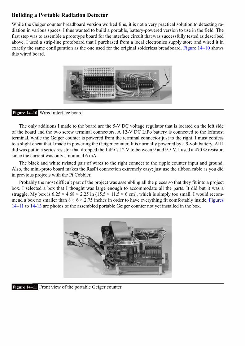
Building a Portable Radiation DetectorWhile the Geiger counter breadboard version worked fine, it is not a very practical solution to detecting ra-diation in various spaces. I thus wanted to build a portable, battery-powered version to use in the field. Thefirst step was to assemble a prototype board for the interface circuit that was successfully tested as describedabove. I used a strip-line protoboard that I purchased from a local electronics supply store and wired it inexactly the same configuration as the one used for the original solderless breadboard. Figure 14–10 showsthis wired board.
Figure 14–10 Wired interface board.
The only additions I made to the board are the 5-V DC voltage regulator that is located on the left sideof the board and the two screw terminal connectors. A 12-V DC LiPo battery is connected to the leftmostterminal, while the Geiger counter is powered from the terminal connector just to the right. I must confessto a slight cheat that I made in powering the Geiger counter. It is normally powered by a 9-volt battery. All Idid was put in a series resistor that dropped the LiPo’s 12 V to between 9 and 9.5 V. I used a 470 Ω resistor,since the current was only a nominal 6 mA.
The black and white twisted pair of wires to the right connect to the ripple counter input and ground.Also, the mini-proto board makes the RasPi connection extremely easy; just use the ribbon cable as you didin previous projects with the Pi Cobbler.
Probably the most difficult part of the project was assembling all the pieces so that they fit into a projectbox. I selected a box that I thought was large enough to accommodate all the parts. It did but it was astruggle. My box is 6.25 × 4.68 × 2.25 in (15.5 × 11.5 × 6 cm), which is simply too small. I would recom-mend a box no smaller than 8 × 6 × 2.75 inches in order to have everything fit comfortably inside. Figures14–11 to 14-13 are photos of the assembled portable Geiger counter not yet installed in the box.
Figure 14–11 Front view of the portable Geiger counter.
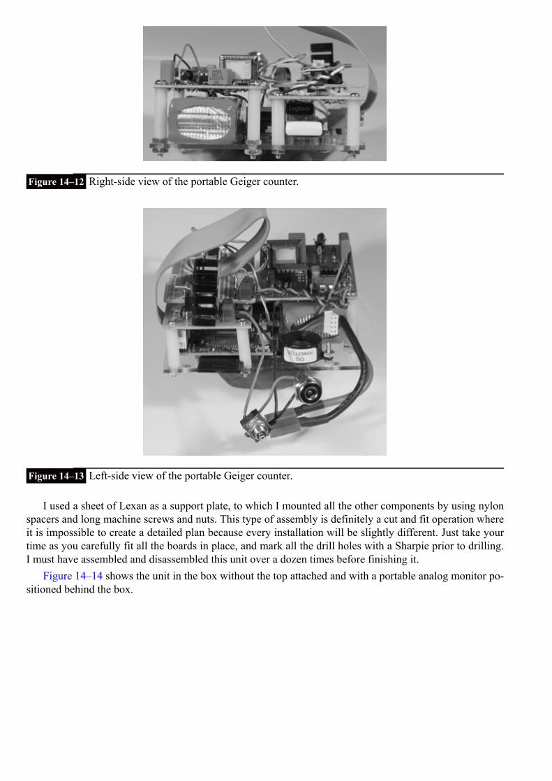
Figure 14–12 Right-side view of the portable Geiger counter.
Figure 14–13 Left-side view of the portable Geiger counter.
I used a sheet of Lexan as a support plate, to which I mounted all the other components by using nylonspacers and long machine screws and nuts. This type of assembly is definitely a cut and fit operation whereit is impossible to create a detailed plan because every installation will be slightly different. Just take yourtime as you carefully fit all the boards in place, and mark all the drill holes with a Sharpie prior to drilling.I must have assembled and disassembled this unit over a dozen times before finishing it.
Figure 14–14 shows the unit in the box without the top attached and with a portable analog monitor po-sitioned behind the box.

Figure 14–14 The Geiger counter installed in a box with the monitor.
The monitor is powered directly from the LiPo battery through a type N power jack installed in the box.Also notice that I drilled a 5/8-inch hole through the box in order to have access to the RasPi’s analog videosocket. There is an on/off switch also mounted above the monitor power socket that controls the power toevery component in the box.
If you look carefully at Fig.14-14, you will notice a ½-inch hole drilled through the box just to the leftof the GM tube. This hole is also capped with a metal plug. I drilled this hole so that beta particles could bedetected by the Geiger counter if desired. Remember from the earlier discussion that beta particles can beshielded by a thin plastic layer, so this box would certainly stop them.
Operating the Portable Geiger CounterI installed the WiPi adapter in one of the RasPi’s USB ports and put a Bluetooth adapter in the other one forthe wireless keyboard and mouse unit that we also used in the robot car project. After you do this, connectthe analog monitor through the side hole for the video. Don’t forget to plug in the power jack. It is then asimple task of turning on the power and doing a normal boot operation. The command to start the programis:
That should be it; you should now be seeing the radiation readings displayed on the monitor. I also con-nected to the Geiger counter remotely to capture a screenshot of the unit in action. Figure 14–15 shows ascreenshot of the Geiger counter registering normal background readings.

Figure 14–15 Portable Geiger counter in operation.
Finally, you can connect to the Internet if you want, which makes this unit quite unique—not manynetwork-enabled Geiger counters are available, especially at the cost of this one.
Modifications and ExpansionsOne modification to this project that would be useful is to attach a multi-line, I2 C, LCD display to the boxand, thereby, remove the need for the monitor. You would need to make the program start automaticallyupon boot up, but that is relatively easy to accomplish with the many great tutorials available on the web.
I would definitely use a larger box in order to make it easier to have access to the LiPo battery. Recallthe warning in the robot car chapters: Never use a standard automotive or even a regular power supply torecharge the LiPo battery. I just hope no one who builds this project is foolish enough to plug a wall wartinto the external monitor socket in hopes of recharging the battery.
The program may also be extended to report radiation readings remotely. Right now, the program simplydiscards old readings, but it could be easily changed to record those readings in a log file and to send themremotely to clients using a built-in web service.
SummaryThis chapter began with a discussion on radioactivity and the origins of radon gas. A distinction was madebetween activity levels and absorbed dose. Examples were provided to help you understand how radiationactivity and dose levels are related.
A brief discussion followed on how the project’s Geiger counter would function, along with a detailedexplanation of how to interface the counter to the RasPi.
We then looked at an initial test configuration with sample readings taken from both background radi-ation and a uranium ore sample. The controlling Python program was also discussed.
Next came a detailed construction procedure on how to convert the test configuration into a portableinstrument. A demonstration of this portable Geiger counter along with its networking capability followed.
Finally, I suggested some modifications and expansions to further improve the utility of this project.

CHAPTER 15
Serving up Time with an RTC and NTP
IntroductionThis project is focused on how the RasPi keeps track of time both locally and through a network. As designed, theRasPi contains no means to set or track time. This design decision was made both to keep the cost down and to minim-ize the printed circuit board (PCB) size. In addition, the capability would be available in the rev B model because it hasa network port that is able to connect to a public Network Time Protocol (NTP) server. An automatic NTP connectionis also built into the standard Wheezy Raspian Linux distribution designed for the RasPi.
The RasPi A models and B models without Internet access do not have public NTP service and, thus, require an-other means to set and track time. This is where a hardware peripheral known as a real-time clock (RTC) becomes veryhandy. First we’ll discuss the RTC and then take a comprehensive look at the NTP service.
Real-Time Clock (RTC)The RTC module, which has been available for many years, first appeared with the advent of the PC in the early 1980s.There were timing systems available before that period, but they were fairly complex and expensive devices and suit-able mainly for mainframe computers. The RTC introduced with the first PC was based upon an integrated chip namedthe MC146818, which was manufactured at that time by the Motorola Corporation. A modern version of that chip isused in this project. It is the DS1307, pictured in Fig. 15–1, which is manufactured by the Dallas Semiconductor com-pany, previously mentioned in Chaps. 10 and 11.
Figure 15–1 DS1307 DIP.
The DS1307 is an I2C controlled device, as may be readily seen by the block diagram shown in Fig. 15–2. It isa fairly simple peripheral that uses a quartz-crystal-controlled oscillator in conjunction with a binary counter that islabeled as an oscillator and divider in the diagram. The crystal is rated at a nominal 32,768 Hz frequency (equival-ently 32.768 kHz), which is exactly the value of 2 raised to the fifteenth power. Therefore, a 15-bit binary counter willoverflow or reset once every second if a 32.768 kHz signal is input to the first stage of the counter. Theoretically, thissetup will produce a once per second clock tick. Notice, I used the word theoretically, as the reality is that the clockcrystals typically used with the DS1307 do not produce a perfect 32.768 kHz waveform. Figure 15–3 shows the actualcrystal used in this project.

Figure 15–2 DS1307 block diagram.
Figure 15–3 RTC crystal.
You should clearly see the frequency in kHz printed on the metal can enclosing the actual piezo-electricelement. These generic type RTC crystals typically will have accuracy within ± 30 seconds/month whenproperly loaded with a matching 6 picofarad (pF) crystal and operated at a nominal 23°C ambient temper-ature. The operating temperature is the key parameter that affects clock accuracy, assuming the correct ca-pacitance loading is used. Figure 15–4 shows the temperature effect as it deviates from the standard 23°Ccalibration point.

Figure 15–4 Temperature versus RTC frequency deviation.
The ± 30 seconds/month accuracy will be maintained for a RasPi operating in a home or office.However, a RasPi that operates in severe environments should expect significant reduction in RTC accuracy.
Another key feature of the RTC is the ability to maintain the time even if the host processor is turnedoff. This is made possible by using a long-life battery to power the oscillator and non-volatile (NV) RAM(write mode) in the DS1307 chip. A lithium coin cell battery is normally used for this purpose after the hostis powered off. A coin cell will often last for many years before exhausting its energy. The current date andtime is continually stored in the NV RAM 56-byte memory.
Figure 15–5 shows the RTC breakout board used in this project. It is built from kit number 264 pur-chased from Adafruit Industries. It uses the DS1307 chip along with the crystal shown in Fig. 15–3. Thereare two resistors not installed, but are shown as placeholders on the PCB. This is because the RasPi alreadyhas two pull-up resistors attached to the Serial Data Line (SDA) and Serial Clock (SCL) control lines, neg-ating the need for these components.
Figure 15–5 RTC breakout board.
The building kit is very easy to put together because there are only five components to install includingthe coin-cell holder. Each one has a placeholder noted on the PCB. Just be very careful when soldering thecrystal to the board because you do not want to overheat it or excessively bend the fragile leads.
The RTC breakout board is connected to the RasPi by using a solderless breadboard with the Pi Cobblerprototype connector. The wiring connections are detailed in Table 15–1.
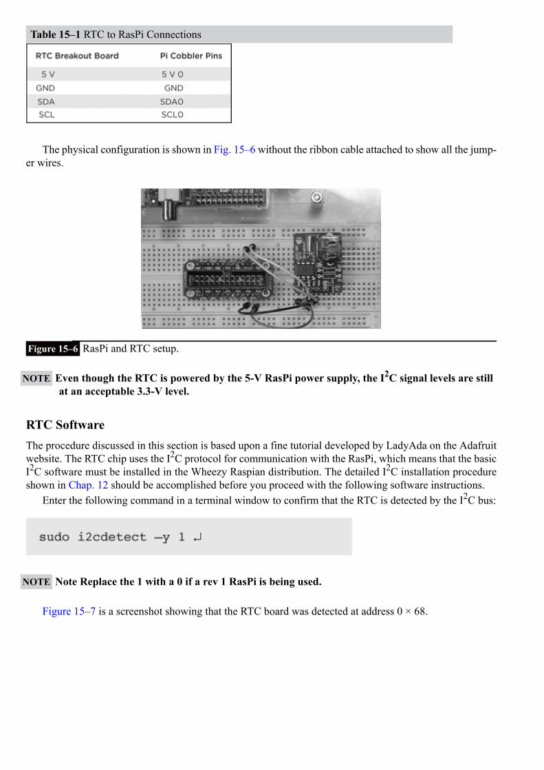
Table 15–1 RTC to RasPi Connections
The physical configuration is shown in Fig. 15–6 without the ribbon cable attached to show all the jump-er wires.
Figure 15–6 RasPi and RTC setup.
NOTE Even though the RTC is powered by the 5-V RasPi power supply, the I2C signal levels are stillat an acceptable 3.3-V level.
RTC SoftwareThe procedure discussed in this section is based upon a fine tutorial developed by LadyAda on the Adafruitwebsite. The RTC chip uses the I2C protocol for communication with the RasPi, which means that the basicI2C software must be installed in the Wheezy Raspian distribution. The detailed I2C installation procedureshown in Chap. 12 should be accomplished before you proceed with the following software instructions.
Enter the following command in a terminal window to confirm that the RTC is detected by the I2C bus:
NOTE Note Replace the 1 with a 0 if a rev 1 RasPi is being used.
Figure 15–7 is a screenshot showing that the RTC board was detected at address 0 × 68.

Figure 15–7 Detecting the RTC board on the I2C bus.
The next step is to load the RTC module software, which is done by entering this command:
The modprobe application loads what is known as a loadable kernel module (LKM), which in this case,is named rtc-ds1307. You may have to run the following two commands if the LKM is not found:
The next step is to instantiate the RTC object, which you must do at the root level using the followingcommands:
NOTE i2c-1 is for a rev 2 RasPi. Use i2c-0 for a rev 1 RasPi.
You may now check the time stored in the RTC by typing the following:

The RTC should report back, Jan 1 2000, if it has not been previously set. Figure 15–8 is a screenshotshowing all the previous commands as well as the time. Notice that it reported a date different from Jan 12000 because I had rebooted the RasPi in the setup.
Figure 15–8 Screenshot of the RTC setup.
You will now need to set the current date and time for the RTC. This may be done in two ways. The firstand probably easiest is to connect the RasPi to an Internet accessible network in order to set the current dateand time. Simply plug in an Ethernet cable or a Wi-Fi adapter, and let the RasPi seek out and set its clockusing the NTP service. After a minute or two, the RasPi should have acquired and set its system time to thecurrent date and time.
The second method of setting the date and time is simply to enter it at a terminal prompt using the fol-lowing sample as guidance:
The RTC will automatically reset its internal memory based upon your manual input.You should always check on the system time after setting it by entering:
You may also force the RTC clock to synchronize to the system date and time by entering the following:
Next check the time reported back by the RTC by typing in the following:

Figure 15–9 is a screenshot showing the set time command as well as the time reported back by theRTC.
Figure 15–9 Screenshot of setting and checking the RTC date and time.
The next portion of this procedure concerns how to permanently configure the RasPi to use the RTCboard. The rtc-ds1307 module must first be added to the LKM list that is stored in the /etc/modules file. Todo this, edit the modules file by adding a line, “rtc-ds1307,” at the end of the list. Figure 15–10 shows thisedit using the nano editor.
Figure 15–10 LKM module screenshot.
The last remaining step is to edit a file named rc.local that is located in the/etc directory. This file con-tains scripts that are run at the end of the boot process, which is how the RTC object will be created oncethe following script lines are entered into the rc.local file:

NOTE i2c-1 is for a rev 2 RasPi. Use i2c-0 for a rev 1 RasPi.
Figure 15–11 shows this edit using the nano editor.
Figure 15–11 The edited rc.local file screenshot.
I shut down the RasPi after completing the previous configuration steps and waited until the next dayto restart the system in order to check the RTC function. Figure 15–12 shows that the date function workedperfectly, indicating that the RTC was performing as expected and accurately tracking the passage of time.
Figure 15–12 Screenshot of the date function.
Introduction to the Network Time Protocol (NTP)NTP is probably the most common way time is set and maintained in today’s modern networks, includingthe Internet. The protocol itself was created by Dr. David Mills at the University of Delaware in 1985. Cur-rently, Dr. Mills is an emeritus professor at the University of Delaware, where he was a full professor from1986 to 2008. He, along with a team of volunteers, is still involved with the development and maintenanceof NTP.

In reality, the NTP is implemented by a layered hierarchical network of computers, each one of whichis set up as a time server running the NTP protocol. Figure 15–13 is a representative block diagram of thishierarchy.
Figure 15–13 NTP server hierarchy.
The layers in the NTP hierarchy are referred to as strata, starting with 0 and progressing to as high as256. In reality, layers 16 or higher are considered unsynchronized and are probably not implemented. Thehighest layer, shown in the figure, is stratum 0, which consists of clock sources from which the actual timeis referenced. There are a variety of primary clock sources available in the public NTP network, includingsophisticated atomic clocks, GPS clocks, and the National Institute of Standards and Technology (NIST)time signal radio station WWVB to name a few. Stratum 1 connects directly to the clock sources and usu-ally is a high-quality clock server source, but this is not always the case. NTP does not inherently guaranteethat a server situated in the lowest-numbered stratum will provide the highest quality or most reliable clocksignal. The reason for this is that the servers are networked and are constantly crosschecking the clock sig-nals from other servers, both in their same stratum as well as in the strata situated logically above them.Poor-quality clock signals will be rejected from adjoining servers, and only quality signals will be passed onto other servers. Thus, it is entirely possible to have a server on a lower-level stratum (with a higher stratumnumber) provide a higher-quality clock signal than a server on a stratum closer to the primary clock sources.Don’t worry if all this sounds a bit confusing; I provide it only as background to promote your awarenessof the underlying NTP structure.
A series of public NTP servers connected to the Internet are known as pool servers. The URLs for theseservers are stored in the ntp.conf file located in the /etc directory. Figure 15–14 is a screenshot of this file.

Figure 15–14 Screenshot of the ntp.conf file.
There are four NTP servers listed, starting with 0.debian.pool.ntp.org through 3.debian.pool.ntp.org.The RasPi will typically connect to one or more of these servers each time it is booted. I am unsure whetherthe lead number 0 to 3 represents a stratum level; however, it is irrelevant, as the NTP software will auto-matically select the best clock signal and use it.
The RasPi NTP software is run as a daemon and requires no manual intervention for normal operation.The software is formally named ntpd with the “d” indicating a daemon application.
Building a RasPi NTP ServerI will show you how to build an NTP server that can provide accurate clock signals without the need to con-nect to one of the pool servers described above. Sometimes it is necessary to provide an independent NTPnetwork server that does not rely on an Internet connection and can serve as a central clock source for allnetworked computers. There are commercial NTP servers available, but they typically cost anywhere from$1500 to $2000. Using a RasPi with a GPS will drop the cost to less than $100 and will provide the desiredfunctionality.
The GPS used in this stage of the project is the same model previously discussed in Chap. 5. I will notrepeat all the background and setup information provided in that chapter and will simply assume that youwill follow those instructions in establishing the GPS to RasPi UART communications link. Refer to Fig.5–15 in Chapter 5 to see the essential wiring required to connect the GPS module and the RasPi. You shouldensure that the gpsd package is installed on the RasPi, as you will need it to process the GPS clock data.I recommend that you also install the CuteCom terminal control program. Using that program will enableyou to easily confirm that both the UART link and the GPS module are functioning properly. Again, simplyfollow the procedures detailed in Chap. 5 to set up the GPS module and the RasPi to use the UART com-munications device ttyAMA0.
The ntp.conf file located in the etc directory must be edited to force the ntpd application to use the GPSinstead of one of the pool servers. I commented out all the pool servers and added the following two linesto that section of the file:

Figure 15–15 is a screenshot of the edited ntp. conf file.
Figure 15–15 Screenshot of the ntp.conf file.
NOTE The pool servers will be uncommented after the GPS time server functionality has beenproven, since it is good practice to leave these servers available.
Next the following series of commands will set up and run the GPS module as a clock source for theRasPi. Ensure that no Wi-Fi adapter or Ethernet cable is attached because they could provide a clock sourceif you didn’t comment out the pool servers listed in the ntp.conf file. All the commands should be enteredin the sequence shown:

The killall gpsd command stops the gpsd daemon so that a logical socket link may be establishedby the next command. The /dev/ttyAMA0 parameter in the second command specifies that the GPS datawill be sourced from the UART. The last two parameters, –F /var/run/gpsd.sock, set up a controlsocket for device adds and removals with the full path description to the socket. The last command startsthe ntp daemon, at which point it will attempt to retrieve the clock signal from the source specified in thentp.conf file.
The GPS module will continue to blink its LED until a solid lock is obtained on four or more satellites.A reliable time is not available until the LED stops blinking, which could take several minutes dependingon the antenna signal strength. I used an external antenna and was able to consistently obtain a good lockin about two minutes. You may now use the date command to check on the precision time that is obtainedfrom the GPS system.
The ntp.conf file must now be edited if all is well at this stage in the process. The following line indicatesthat the RasPi should be available as a stratum 10 server to other networked computers if desired:
Additionally, uncomment and edit the following existing line in ntp.conf:
I changed this line to:
This line allows the NTP server to broadcast the time to all computers located on the same subnet as theserver. Your subnet may be slightly different. Type these three commands to ensure that the NTP server isoperating:
I recommend using a program named ntpdate to confirm that a client computer is connected to and usingthe NTP server. Install the ntpdate program by typing:
Type the following command on the client computer (another RasPi) that is intended to use the NTPclock signal to confirm it is being received:

The local IP address for my NTP server is 192.168.1.43. Figure 15–16 is a screenshot of the ntpdateprogram output, clearly showing that the NTP service is being provided by the RasPi NTP server.
Figure 15–16 The ntpdate program output.
Radio Receiver Clock Source
Originally there was an additional section to this chapter that dealt with a radio receiver clocksource, which was fixed tuned to WWVB, the U.S. synchronized time source located in Ft.Collins, CO. WWVB transmits a digital clock signal on 60 kHz 24 hours per day, seven days aweek. There are several low-cost receiver kits available that can receive WWVB throughout thelower 48 states. I used a $15 kit that is available from PV Electronics, which is actually situatedin the UK. I stated all of the above because even though the receiver functioned properly, theRasPi itself generated so much radio frequency interference (RFI) that it literally swamped outthe WWVB signal. The RasPi is FCC certified to be compliant with class B, low-power consumerdevices; however, it is not required to be tested for signal emission interference (EMI) at levelslower than 450 kHz. Obviously, 60 kHz is much lower than the minimum EMI requirement, andthus, it acts as an inadvertent interference, while being perfectly compliant with all FCC regula-tions for this device type. The conclusion is not to use the RasPi as a WWVB controller unlessyou are willing to experiment with various shielding techniques to mitigate the inadvertent inter-ference, which I did without a lot of success.

SummaryThe first part of the chapter covered how to set up a hardware clock to be used with the RasPi because itdoes not incorporate one and would lack a time capability if not connected to the Internet. The hardwareclock was based on the DS1307 chip and used the I2C bus to communicate with the RasPi. The clock boardalso incorporated a lithium coin cell battery that maintained the time even if the RasPi was turned off.
Next, I presented a brief background about the origin and function of the Network Time Protocol (NTP)that the RasPi uses when connected to the Internet. The NTP is implemented on the RasPi by the ntpd dae-mon, which is configured by a file named ntp.conf located in the etc directory.
Finally, I presented a section on how to create your own NTP server based upon a GPS clock source.The GPS module, first shown in Chap. 5, was the source used. It communicated with the RasPi using theUART link. Several changes had to be made to the ntp.conf file to enable the NTP server function. I finishedthe section discussion by demonstrating how to install and use the ntpdate application to test and prove thata client computer on the local network was actually using the RasPi NTP server.

Index
Please note that index links point to page beginnings from the print edition. Locations are approximate in e-readers,and you may need to page down one or more times after clicking a link to get to the indexed material.
# (comments), 27== (equal signs), 37. (Linux command), 17.. (Linux command), 17
AAbsorbed dose (radiation), 176, 177Accessing GPIO pins, 23–26Acknowledgment (ACK) packets, 89, 90Adafruit Industries, 16, 23, 61, 62, 65, 115–117, 156, 161, 171, 189, 190ADC (see Analog-to-digital conversion)Advanced Linux Sound Architecture (ALSA), 31–34Advanced packaging tool (apt), 26Aeon Labs, 94alarm.py, 111, 112Alpha particles (radiation), 175ALSA (see Advanced Linux Sound Architecture)amixer app, 33Amp (electronic amplifier) circuit, 76Analog audio output, 7
ALSA, 31–34frequency response, 33–34testing, 33
Analog composite video connector, 6–7Analog-to-digital conversion (ADC):
for earthquake detector project, 76–77on PIC microprocessor, 76in weather station project, 130
Android, remote logic control with, 147–150aplay app, 35Application Layer Protocol Rules, 67
(See also NMEA 0183 standard)apt (advanced packaging tool), 26apt-get command, 26Arduino series, 13Atomic clocks, in GPS system, 60Audio:
analog, 7, 31–34camera controller project, 48–49, 52–54file formats for, 34–37

HDMI for, 5–6MP3 player project, 31–41
Audio connector, 7
BBack feeding, 165Battery power, 41, 158, 165, 189BCM2835 microprocessor (Broadcom), 2–3, 20Becquerel (Bq), 176Beta particles (radiation), 175Binary data storage, 81–82Bit-banging, 13, 80Blinking LEDs (see LED blinker project)Bluetooth:
defined, 156robotic car project, 167–171
Boe Bot chassis, 156, 157Bq (becquerel), 176Broadcom, 1, 2Broadcom BCM2835 microprocessor, 2–3, 20Broadcom VideoCore IV GPU, 3Browser, testing HTTP web server with, 150–153Bus network, 12Buy vs. build decision, for camera controller project, 48
CCamera:
digital serial, 8, 9webcam, for home security, 103–104, 106, 109–111
Camera controller project, 43–56audio module, 48–49electronic flash, 45–47interface connections, 50–55laser module, 49–50optoisolator interfaces, 47–48project requirements, 44shutter operation, 44–45stop-action pictures, 43–44time-lapse function, 55
Camera Serial Interface (CSI-2), 8CameraControl.py, 52–53Canon, 47Canon 40D DSLR, 44, 45Canon 420EX electronic flash, 45–46cat filename (Linux command), 17cd (Linux command), 17cd .. (Linux command), 17CDMA (Collision Detection Multiple Access), 89, 90CEC (Consumer Electronics Control), 6
Celestial almanac, 60cgps app, 69Chassis (robotic car project), 156–160Ci (curie), 176Class designations (SD cards), 4Clocks:
atomic, in GPS system, 60radio receiver clock source, 197real-time, 187–193(See also Time keeping project)
Collision Detection Multiple Access (CDMA), 89, 90Comments (#), 27Comparisons, equal signs for, 37Compass system, 57Conditional statement, 29Connections, 2Connectors (RasPi), 4–10
analog composite video, 6–7audio, 7Ethernet and USB, 7–8for future expansion, 8–9GPIO interface, 9–10HDMI, 5–6power, 5
Console player apps, 36Consumer Electronics Control (CEC), 6Control voltages (for electronic flash), 47Controllers:
camera controller project, 43–56home security controller project, 103–113local and remote logic controller project, 139–153NFC/RFID reader project, 116in Z-Wave networks, 91–92
CSI-2 (Camera Serial Interface), 8Curie (Ci), 176Current level (for optoisolators), 47Current limits, 10–11CuteCom, 65–67cwiid package, 169
DDAC (digital-to-analog converter), 77Dallas Semiconductor, 129, 187Data analysis (earthquake detector project), 82–83Data storage, 81–82Dawson, Michael, 17DC (direct current), 5DHCP (Dynamic Host Configuration Protocol), 8Differential mode (ADC), 77Digital repeater (digipeater), 88

Digital signal voltage level, 10Digital Single Lens Reflex (DSLR) shutter, 44–45Digital Video Interface (DVI), converting from HDMI to, 6Digital-to-analog converter (DAC), 77Dilution of precision (DOP) numbers, 71DIP (dual in-line package), 47Direct current (DC), 5Display Serial Interface (DSI) connector, 9DoD (U.S. Department of Defense), 57Donationware, 147DOP (dilution of precision) numbers, 71Downey, Allen, 17Downloading GPIO library, 25–26DRAM (dynamic random access memory), 3DrGPIO app, 147, 150Drive motors (robotic car project), 156–160DS18B20 chip, 128, 130–131DS1307 chip, 187–189DS2438A chip, 128–130DSI (Display Serial Interface) connector, 9DSLR (Digital Single Lens Reflex) shutter, 44–45Dual in-line package (DIP), 47DVI (Digital Video Interface), converting from HDMI to, 6Dynamic Host Configuration Protocol (DHCP), 8Dynamic random access memory (DRAM), 3
EEarthquake detector project, 73–85
analog-to-digital conversion for, 76–77connecting/testing MCP3008, 79–82operational system, 83–84seismic data analysis, 82–83seismic sensor design, 75–76seismology basics, 73–74Serial Peripheral Interface for, 78
8 Channel I/O board:for logic controller project, 139, 140, 144–146remote access to, 151–153test sequences for, 144–146
Einstein, Albert, 60Electrical buffers, 23Electronic amplifier (amp) circuit, 76Electronic flash, 45–47, 52E-mail notification:
home security system project, 109–111NFC/RFID reader project, 123
End of Frame (EoF) byte, 89Ephemeris, 60Ethernet connector, 7–8
in local and remote logic controller project, 140

and 1-Wire connection, 126Expansion connectors, 8–9extract_data.py, 122–123
FFabless suppliers, 2Filesystem in Userspace (FUSE), 143–144Flash, electronic, 45–47, 52Flip-flop operation, 49Floating inputs, 1504-wire serial bus, 12
(See also Serial Peripheral Interface (SPI))Freescale Semiconductor, 128Frequency response (of analog audio), 33–34Full-duplex communication, 78FUSE (Filesystem in Userspace), 143–144Future expansion connectors, 8–9
GGalileo system, 57Gamma rays (radiation), 175Garden-gate seismic sensor, 75Gas-tight connections, 24Geiger counter:
K2645 Geiger-Muller counter, 175, 177–179portable, 183–185
geiger.py, 180–181General Purpose Input/Output (GPIO) connector, 9–10
accessing pins, 23–26current limits, 10–11GPIO library, 25–26input state for pins at power on, 27interrupts, 11, 12isolating pins, 47–48making pins programmable, 24–25Pi Cobbler prototype connector for, 31, 32pin assignments, 9pin expansion, 11voltage levels, 10
General relativity, theory of, 60Global Positioning System (GPS):
defined, 57functioning of, 58–60(See also GPS project)
Global Specialties, 48GLONASS system, 57Gmail, 109Google, 147, 158GoPro Hero3, 173

GPIO connector (see General Purpose Input/Output connector)GPIO library, 25–26GPIO pin expansion, 11GPS (see Global Positioning System)GPS module:
for NTP server, 195–196Ultimate GPS receiver, 61–66
GPS project, 61–71displaying data, 69–70gpsd apps, 69–71history of, 57–58NMEA protocol, 66–69packet monitor, 70–71Ultimate GPS receiver, 61–66
GPS sensor (for robotic car), 173gpsd apps, 69–71gpsmon app, 70Graphics processing unit (GPU), 2, 3
Broadcom 2835 microprocessor as, 2Broadcom VideoCore IV, 3on SoCs, 1
Gray (Gy), 176GSK-409 audio control switch, 48, 49GUI desktop, 15, 16Gy (gray), 176
HHalf-life, 175Hardware, 2–13
Broadcom 2835 microprocessor/GPU, 2, 3connectors, 4–10current limits, 10–11digital signal voltage level, 10GPIO pin expansion, 11interrupts, 1, 12Linux’s treatment of, 143memory, 3–4Pi Cobbler, 31, 32prototype board (Pi Plate), 23, 24serial protocols, 12–13(See also individual projects)
HD (high-definition) video, 3HDMI (High-Definition Multimedia Interface) connector, 5–6HDMI-CEC compliant devices, remote control for, 6Headless login, 96“Hello World” program, 18, 19Hensley, Brian, 169High-Definition Multimedia Interface (HDMI) connector, 5–6High-definition (HD) video, 3High-level languages, 17

High-voltage optoisolator circuit, 48HIH-4021-001 sensor, 128Hive behavior (for robotic car), 173Hobby Boards, 125, 139, 140Home automation project, 87–101
Open Z-Wave software, 96–101RasPi and Z-Wave interface, 94–95SSH login, 95–96Z-Wave mesh network for, 87–94
Home automation system:defining, 87popular technologies for, 89tasks handled by, 88
Home ID (Z-Wave), 91Home security controller project, 103–113
additional sensors, 111, 113laser trip assembly, 104–105laser trip program, 111Motion (software package), 105–109protected security zone in, 104webcam selection, 103–104webcam viewing, 109–111
Honeywell, 128Hop kill, 88
II2C (see Inter-Integrated Circuit)IDLE, 18–20
desktop icons, 18running as roots, 28
if/else conditional test, 38Image file, 15–16import, 29Industrial, Scientific, and Medical (ISM) band, 87, 115Initial startup, 13–15Inputs:
5-V device, 10floating, 150switch, 37–38
INSTALL.txt. file, 26INSTEON technology, 89Intellectual Property (IP), 1, 2Inter-Integrated Circuit (I2C), 9
initial test, 162–163robotic car project, 161–163, 167serial protocol, 12and servo controller, 161–162
Internet Protocol (IP) address, 8Interpreted languages, 18Interrupts, 11, 12
Intrusion detection (see Home security controller project)Inverted pendulum seismic sensor, 75Ionizing radiation, 175IP (Intellectual Property), 1, 2IP (Internet Protocol) address, 8IR light (for robotic car), 173IR sensor (for robotic car), 173IRNSS system, 57ISM (Industrial, Scientific, and Medical) band, 87, 115ISO seven-layer network model, 88, 89
KK400r keyboard/mouse combination (Logitech), 166, 167K2645 Geiger-Muller counter, 175, 177–179
LLadyAda, 190Laser module (for camera controller), 49–50, 52, 53Laser trip devices:
for camera controller project, 48–50for home security controller, 104–105, 111
LCD (liquid crystal display), 40LDT0-028K sensor, 75, 76Learn.Adafruit.com, 79“Least privilege” principle, 16Least significant bit (LSB), 78LED (light-emitting diode), 8LED blinker project, 23–29
blinking the LED, 28–29preparation for, 23–26turning on the LED, 27–28
LG, 6libnfc, 116–121
data communication with, 116installing, 117–121
Light-emitting diode (LED), 8(See also LED blinker project)
lightscontrol app, 97–99Lightweight X11 Desktop Environment (LXDE), 16–17Li-ion charger board, 157, 158Linux, 1, 13
ALSA, 31–34commonly used commands, 17file names in, 25, 26fundamentals of, 16–17hardware treatment by, 143initial startup, 13–15preparing SD cards, 15–16on preprogrammed SD card, 3, 4

user access, 16Liquid crystal display (LCD), 40Lithium-ion polymer (Li-Po) battery, 165, 166, 183, 185LM7805 three terminal chip, 165Loadable Kernel Modules (LKM), 32, 190Local and remote logic controller project, 139–153
Android remote control, 147–150FUSE, 143–144hardware, 143and Linux, 1431-Wire external control board, 139–141owfs installation and configuration, 141–143Python test program, 146sniffer monitoring, 147test sequences for 8 Channel I/O board, 144–146testing web server with browser, 150–153
Login:headless, 96SSH, 95–96
Logitech C920 webcam, 103Logitech K400r keyboard/mouse combination, 166, 167Looping, 29Lossless compression, 34, 35Lossy compression, 34, 35Loughlin, Thomas, 96, 97, 99Low Voltage Differential Signaling (LVDS) serial display, 9Low-level languages, 171s (Linux command), 17LSB (least significant bit), 78LVDS (Low Voltage Differential Signaling) serial display, 9LXDE (Lightweight X11 Desktop Environment), 16–17
MMagnetic induction, 115Master devices:
in earthquake detector project, 78in weather station project, 129
Maxim, 129Maxim DS18B20 chip, 128, 130–131Maxim DS2438A chip, 128–130MCl46818 chip, 187MCP3008 ADC, 77
connecting/testing, 79–82as slave device, 78
Measurements Specialties Corp., 75Member (of an operator), 29Memory, 1, 3–4Metal-oxide-semiconductor field-effect transistor (MOSFET), 131–132Micro USB power connector, 5microBuilder.eu, 115, 116

Microchip, 76, 77Microprocessors:
Broadcom 2835, 2–3PIC24HJ64GA002, 76on SoCs, 1in Z-Wave devices, 91
Microrem (mrem), 182Mills, David, 193mkdir directory (Linux command), 17modprobe app, 32, 190Moment magnitude scale, 73Monitors:
analog, 7choices of, 6
Monk, Simon, 17MOSFET (metal-oxide-semiconductor field-effect transistor), 131–132Most significant bit (MSB), 78Motion (software package), 103, 105–109
features of, 106setup of, 106–109
Motorola Corporation, 187MP3 files:
playing, 35–37WAV files vs., 34–35
MP3 player project, 31–41ALSA, 31–34audio file formats, 34–37expanding, 40–41hardware switches, 37–38and operational speed of RasPi, 38–39player schematic, 40prototype connector, 31, 32requirements, 39–41stereo speaker, 31–34testing, 40writing program, 39–40
MP3_Player.py, 39–40MP601 operational amplifier, 76mpg 123, 35–37, 40mpg 321, 35MPXA4115A sensor, 128MSB (most significant bit), 78Multidrop network, 12
NNACK (Negative Acknowledgment) packets, 89, 90nano (text editor), 17, 19–20National Marine Electronics Association (NMEA), 58, 66
(See also NMEA 0183 standard)Near Field Communications (NFC):

data communications flow, 116defined, 115functioning of, 115hardware, 115–116(See also NFC/RFID reader project)
Negative Acknowledgment (NACK) packets, 89, 90Network Time Protocol (NTP), 187, 193–197Newton, Rona, 75NFC (see Near Field Communications)NFC Shield, 115nfc-poll program, 121–122NFC/RFID reader project, 115–124
future expansion, 122–123hardware installation, 121initial checkout, 121–122libnfc installation, 116–121NFC data communications flow, 116NFC hardware, 115–116passive and active modes of operation, 115project program, 122
Nikon, 47NMEA (National Marine Electronics Association), 58, 66NMEA 0183 standard, 66–69
GPS message types, 68latitude and longitude formats, 67–68parsed GPS messages, 68–69
NTE3041 optoisolator, 47, 48NTP (Network Time Protocol), 187, 193–197ntp.conf, 194–196ntpdate, 196NXP PN532 microcontroller, 116Nyquist rate, 77
OObject-oriented programming, 29Occidentalis GUI desktop, 16Occidentalis v.2, 161One-third octaves, 33, 341-Wire external control board, 139–1411-Wire File System (see owfs)1-Wire Sniffer, 132, 135–137, 140, 1431-Wire weather station project, 125–138
design of, 125–129future expansion, 1381-Wire protocol, 129–1321-Wire Sniffer, 132, 135–137owfs software package, 133–134packet sniffing, 135–137setting up, 132–133viewing weather data, 134–135

One-wire serial protocol, 16Open Z-Wave software, 96–101OpenGL ES 2.0 standard, 3Operational amplifier (op amp), 76Operational speed (of RasPi), 38–39Operational system, for earthquake detector, 83–84Optoisolator interfaces (camera controller project), 47–48, 51Optotriac, 48Oscillator and divider, 187Output, to 5-V logical devices, 10Overclocking, 3ow_eight.py, 146owfs (1-Wire File System), 125
in local and remote logic controller project, 141–143, 152, 153in weather station project, 133–134
PPacket sniffing (1-Wire weather station project), 135–137Parallax, 156, 157Parasitic power supply, 131Password, for initial startup, 14PCB (printed circuit board), 1Permission Denied error, 144Philips Company, 12pi (user), 16Pi Cobbler, 31, 32, 37
connection to GPS receiver, 64in earthquake detector project, 79, 81in NFC/RFID reader project, 121in remote logic controller project, 149in robotic car project, 165in RTC project, 189
Pi Plate (see Prototype board)PIC24HJ64GA002 microprocessor, 76Pink noise, 33, 34Pink-noise signal, 34Play Store app, 147PMS (“Poor Man’s Seismograph”), 75PN532/NFC breakout board, 115–117, 121Pool servers, 194, 195“Poor Man’s Seismograph” (PMS), 75Portable controllers, 91Portable radiation detector, 182–185Portable stereo speaker, 31–34Positive power-supply voltage (Vdd), 10Potentiometer, 76Power connector, 5Preprogrammed SD card, 3, 4Print function, 18, 19Printed circuit board (PCB), 1
Programming languages:color coding of code, 19high- and low-level, 17interpreted, 18for RasPi (see Python programming)
Programming the Raspberry Pi (Simon Monk), 17Prolific, 62Prototype board (Pi Plate), 23, 24, 31, 32Pulse-width modulation (PWM), 161Pulse Width Modulation (PWM) /Servo Driver I2C Interface board, 156, 161–163Putty.exe, 95, 96PV Electronics, 197P-waves, 73, 74pwd (Linux command), 17PWM (pulse-width modulation), 161PWM/Servo Driver I2C Interface board, 156, 161–163.py extension, 19Python programming, 13, 17–20
comments in, 27data storage in, 81–82looping in, 29modifying program, 28–29nano text editor for, 17, 19–20saving code, 28shell versions, 18, 19website for, 17writing program in, 19–20
Python Programming for the Absolute Beginner, 3e (Michael Dawson), 17Python programs, xiPython shell:
opening, 20opening/running program in, 28versions 2 and 3, 18
Rrad, 176Radio Frequency Identification (RFID), 115
(See also NFC/RFID reader project)Radio-frequency (RF) signals, 60Radio-frequency (RF) transceiver, 87Radio receiver clock source, 197Radioactivity, 175–178
(See also Radon detector project)Radon detector project, 175–185
initial test configuration, 179–182K2645 Geiger-Muller counter, 178–179modifications and expansions, 185portable detector, 182–185radioactivity and radon gas, 175–178
Radon gas, 175, 176
Ramsey Electronics, 48Raspberry Pi (RasPi), 1–21
Broadcom 2835 microprocessor on, 2–3connectors on, 4–10current limits with, 10–11digital signal voltage level, 10graphics processing unit of, 2, 3hardware for, 2–13history of, 1IDLE application for, 18–20initial startup, 13–15interrupts, 11, 12key components/connections on, 1, 2Linux fundamentals, 16–17memory used in, 3–4Model B, 11PGIO pin expansion, 11preparing SD card, 15–16Python programming for, 17–20serial protocols, 12–13SoC chip on, 1, 2software for, 13–20(See also individual projects)
Raspberry Pi Foundation, 1, 11, 16rc.local, 191Reagan, Ronald, 57Real-time clock (RTC), 187–193Relativity, theories of, 60rem (roentgen-equivalent-man), 177Remote control:
for HDMI-CEC compliant devices, 6home automation system controllers, 91–92local and remote logic controller project, 147–150of security webcam, 109(See also Robotic car project)
Representational State Transfer (REST), 151RF (radio-frequency) signals, 60RF (radio-frequency) transceiver, 87RFID (Radio Frequency Identification), 115
(See also NFC/RFID reader project)Richter magnitude scale, 73, 74Richter numbers, 73, 74rm directory (Linux command), 17rm filename (Linux command), 17Robot_Car.py, 171–172Robotic car project, 155–163, 165–173
block diagram, 165–167Bluetooth software, 167–171chassis and drive motors, 156–160future expansions, 173

I2C software, 167operating the car, 172–173overview of, 155–156program for, 171–172servos, 156, 157, 160–163
Roentgen-equivalent-man (rem), 177root (user), 16, 28Root terminal, 16–17RTC (real-time clock), 187–193
SSample-and-hold circuit, 77Sample rate, 77Samsung, 6SAR (successive approximation register), 77Satellites (GPS), 57Saving code, 28SCL (Serial Clock) control line, 189SCR (silicon-controlled rectifier), 48SD cards:
class designation on, 4inserting/removing with power on, 134preparing, using Windows PC, 15–16preprogrammed, 3, 4rewriting, 16
SD (Secure Digital) flash memory, 3SDA (Serial Data) control line, 189seconds argument, 28Secure Digital (SD) flash memory, 3
(See also SD cards)Secure Shell (SSH), 95–96
login for home automation project, 95–96for NFC/RFID reader project, 117
Seismic waves, 73, 74Seismic_Monitor.py, 83–84Seismology, 73–74
data analysis, 82–83sensor design, 75–76(See also Earthquake detector project)
Sensitivity adjustment (camera controller), 49Sensors:
HIH-4021-001, 128for home security controller project, 111, 113LDT0-028K, 75, 76MPXA4115A, 128for robotic car, 173seismic, 75–76
Serial Clock (SCL) control line, 189Serial Data (SDA) control line, 189Serial interfaces, using uncommitted GPIO pins/software, 13

Serial Peripheral Interface (SPI), 9for earthquake detector project, 78serial protocol, 12
Serial protocols, 12–13I2C, 12SPI, 12UART, 12, 13
Servos (robotic car project), 156, 157, 160–163S5 connector, 9Sharp, 6Sheepwalkelectronics.co.uk, 125Shell editor, 29Shutter operation (camera controller), 44–45Sievert (Sv), 177Sigma Designs, 92Silicon-controlled rectifier (SCR), 48Single-ended mode (ADC), 77SIS (SUC ID Server), 92Sketchup, 158Slave devices:
in earthquake detector project, 78in weather station project, 129in Z-Wave networks, 91
sleep (seconds) function, 28, 29Smartphones, 115, 147–150Sniffers:
local and remote logic controller project, 1471-Wire weather station project, 132, 135–137
SoC (System on a Chip) technology, 1, 2SoF (Start of Frame) byte, 89Software, 13–20apt-get command for, 26IDLE application, 18–20initial startup, 13–15Linux fundamentals, 16–17preparing SD card, 15–16Python, 17–20reuse of, 18updates for, 26(See also individual projects)
Soldering, 23–24Sony, 6SoundModTest.py, 54Speaker, 31–34Speaker-test app, 33Special relativity, theory of, 60SPI (see Serial Peripheral Interface)SPI serial protocol, 12SS (synchronous serial) data link, 78SSH (see Secure Shell)

SSI (Synchronous Serial Interface), 12(See also Serial Peripheral Interface (SPI))
Start of Frame (SoF) byte, 89State values, 169Static controllers, 91, 92Static Update Controller (SUC), 92stdin (standard input device), 41Stereo speaker, 31–34Stop-action pictures, 43–44Strings, storing data as, 81, 82Strobe, 45–47SUC (Static Update Controller), 92SUC ID Server (SIS), 92Successive approximation register (SAR), 77sudo command, 16Super user, 16Sv (sievert), 177Swarm behavior (for robotic car), 173S-waves (earthquakes), 73, 74Switches, 37–38, 48, 49Synchronous serial (SS) data link, 78Synchronous Serial Interface (SSI), 12
(See also Serial Peripheral Interface (SPI))system() function, 39System on a Chip (SoC) technology, 1, 2
TTarget, position, and velocity (TPV), 70Targus Bluetooth adapter, 167–169Tera Term, 62, 63, 65, 66, 135–137Terminal windows, 16–17, 96Test_ADC.py, 79–83Test_File_ADC.py, 81, 82Test_Switch.py, 37–38Text, displaying, 18TFT (thin-film transistor) display, 155, 165Theory of general relativity, 60Theory of special relativity, 60Thin-film transistor (TFT) display, 155, 165Think Python (Allen Downey), 17Threads in Motion software, 106TID (total ionizing dose), 176Time dilation, 60Time keeping project, 187–198
NTP, 193–197RTC, 187–193
Time library, 29Time-lapse photography, 55TimeLapse.py, 55time.sleep (.5), 29

Total ionizing dose (TID), 176Townsend, Kevin, 117TPV (target, position, and velocity), 70Trimble, 158
UUART (see Universal Asynchronous Receiver/Transmitter)Ultimate GPS receiver:
for GPS project, 61–66for robotic car project, 173
Ultrasonic sensor (for robotic car), 173Uncompressed audio files, 34, 35Universal Asynchronous Receiver/Transmitter (UART), 9
in GPS receiver, 61–64in NFC/RFID reader project, 117, 121serial protocol, 12, 13in time keeping project, 195
Universal Powerline Bus (UPB) technology, 89Universal Serial Bus (USB) connector, 7, 8University of Cambridge Computer Laboratory, 1UPB (Universal Powerline Bus) technology, 89Updating software, 26Upton, Eben, 1Uranium ore, 175, 176U.S. Department of Defense (DoD), 57USB connector, 7, 8USB hub, 8User name, for initial startup, 14
VV (voltage), 5Variable resistor, 76Vassallo, Conrad, 97, 99Vdd (positive power-supply voltage), 10Veho 360speaker, 31, 32Velleman, 175VGA (Video Graphic array), 6Video:
HDMI for, 5–6for robotic car, 173
Video connector, 6–7Video Graphic array (VGA), 6Video monitor, choices for, 6VideoCore IV GPU (Broadcom), 3Viewing:
video from home security webcam, 109–111weather station project data, 134–135
Virtual comm port, 63

Volt-ohm meter (VOM), 51Voltage (V), 5Voltage levels:
digital signal, 10for electronic flash, 47GPIO, 10for optoisolator, 48
Voltage output meter (VOM), 80
WWall wart power supply, 126Waveform Audio File Format (WAV) files:
MP3 files vs., 34–35playing, 35
Weather station project (see 1-Wire weather station project)Web server, testing with browser, 150–153Webcam (home security controller):
with Motion, 106selection of, 103–104viewing video from, 109–111
WebIOPi, 147–149, 151Wheezy, 95, 96, 117, 155, 161, 187, 190while True, 29White noise, 33, 34Wi-Fi adapter (for robotic car), 173Wiimote, 155, 156, 166, 169–173Wiimote_Test.py, 170–171win32diskimager.exe, 15WWVB, 194, 197
XX-10 technology, 89, 92
ZZensys, 92ZigBee technology, 89ZOC, 62, 64Z-Stick, 94–95ZW0301 microcontroller chip, 92, 93ZW3102N module, 92–93Z-Wave technology:
“basic” server, 99–101basics of operation, 88–91defined, 89device attributes, 98Home ID in, 91lightscontrol app, 97–99mesh network, 87–94network devices, 91–92

Open Z-Wave software, 96–101packet types, 89, 90RasPi and Z-Wave interface, 94–95Z-Wave chip, 92–94

Thank you for evaluating ePub to PDF Converter.
That is a trial version. Get full version in http://www.epub-to-pdf.com/?pdf_out
Related Documents