Raspberry Pi Hardware Interfacing Jim Windgassen Raspberry Jam Rockville, MD 15 July 2017 REV -

Welcome message from author
This document is posted to help you gain knowledge. Please leave a comment to let me know what you think about it! Share it to your friends and learn new things together.
Transcript

Raspberry Pi Hardware InterfacingJim Windgassen
Raspberry Jam
Rockville, MD
15 July 2017
REV -

Introduction Who am I ?
Electrical engineer for a large U.S. company
Wide background including embedded, analog, digital, power, RF and circuit board design
Novice Raspberry Pi user, experienced Arduino user, 20 years experience using 8051, PIC, ARM processor in custom applications
Passionate engineering hobbyist for 30+ years
What am I doing here ? Basic electrical engineering relevant to Raspberry Pi / Arduino users
Targeted audience is hardware novices and software centric people that want to delve into using Raspberry Pi to interface to hardware
Most of the techniques shown here are generic techniques that are applicable to other platforms (i.e. Arduino)
Show techniques that can be implemented with a limited number of very basic and inexpensive parts
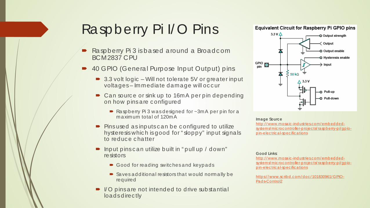
Raspberry Pi I/O Pins Raspberry Pi 3 is based around a Broadcom
BCM2837 CPU 40 GPIO (General Purpose Input Output) pins
3.3 volt logic – Will not tolerate 5V or greater input voltages – Immediate damage will occur
Can source or sink up to 16mA per pin depending on how pins are configured Raspberry Pi 3 was designed for ~3mA per pin for a
maximum total of 120mA
Pins used as inputs can be configured to utilize hysteresis which is good for “sloppy” input signals to reduce chatter
Input pins can utilize built in “pull up / down” resistors Good for reading switches and keypads
Saves additional resistors that would normally be required
I/O pins are not intended to drive substantial loads directly
Image Sourcehttp://www.mosaic-industries.com/embedded-systems/microcontroller-projects/raspberry-pi/gpio-pin-electrical-specifications
Good Links:http://www.mosaic-industries.com/embedded-systems/microcontroller-projects/raspberry-pi/gpio-pin-electrical-specifications
https://www.scribd.com/doc/101830961/GPIO-Pads-Control2

Don’t Scorch Your Pi ! Raspberry Pi and many other electronics are quite susceptible to damage
by static electricity (ESD). Invest in an ESD mat and wrist strap – weakly conductive but enough to drain off
static electricity. This is especially important in the winter when humidity is low ! You must ground the mat and strap properly for it to work !
If your application can tolerate it, putting a resistor in series with an I/O pin is simple protection against over current damage caused by shorting I/O’s to ground or 3.3V R = V/I so to limit current to say 10mA, R = 3.3V / 0.01A = 330 ohms Somewhere between 1k and 10k ohms is a good choice if there is little current
draw
TVS diodes (Transorb) or MOV’s can provide additional protection against over voltage damage, particularly when combined with series resistance May have to solder wires to surface mount device to get low voltage parts (3.3V)
for TVS diodes Can also use 2 schottky diodes such as 1N5817 between GND and +3.3
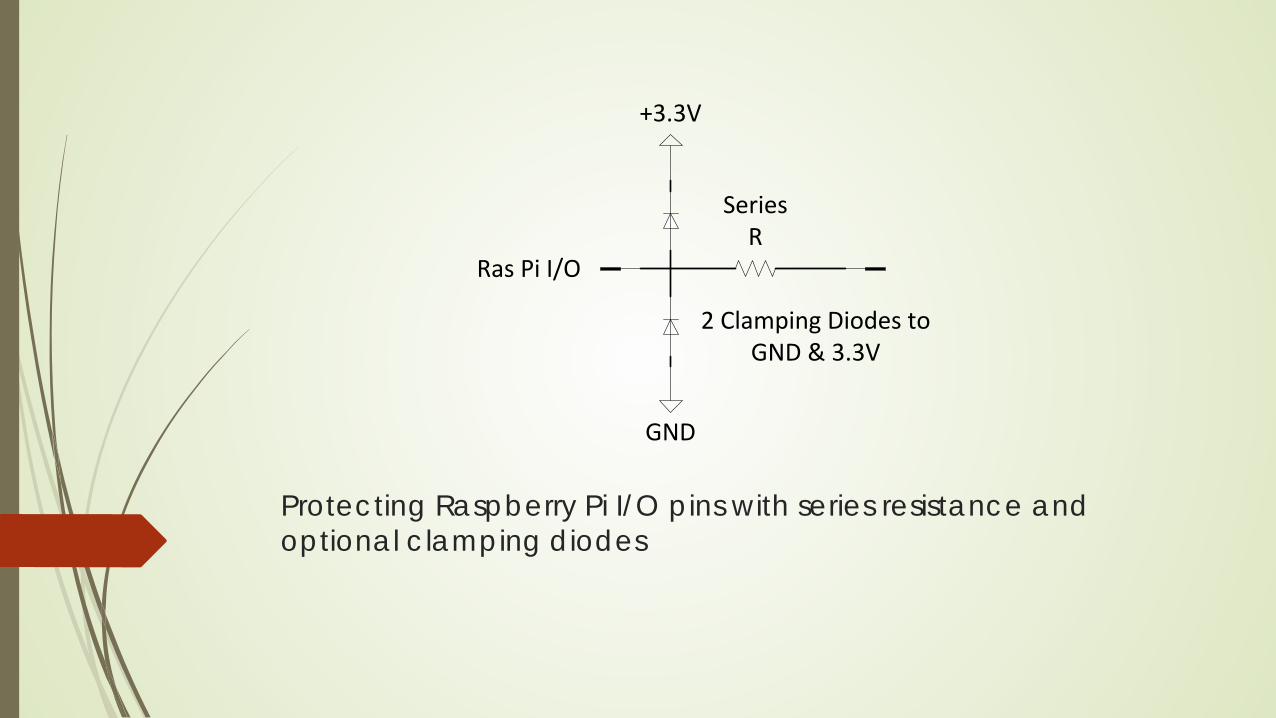
Protecting Raspberry Pi I/O pins with series resistance and optional clamping diodes
Ras Pi I/O
SeriesR
GND
+3.3V
2 Clamping Diodes toGND & 3.3V

Outputs and Power Switching

The Bipolar Transistor Bipolar Transistor – 2 Simple Rules
A tiny current flowing between the base and the emitter causes a MUCH larger current to flow between the collector and the emitter. Typical current gain is ~100 – 500 for a modern small signal transistor.
Transistor starts to turn on when voltage between base and emitter exceeds ~0.7V
Transistors can be used to : Amplify (make bigger) voltages
Amplify current
Act as an on / off switch
NPN vs. PNP Transistors “Complementary”
Opposite Polarity
1mA Into Baseand OutEmitter
100mA intoCollector
andOut Emitter
1mA IntoEmitter andOut Base
100mA intoEmitter
andOut Collector
NPN Transistor With Gain of 100
PNP Transistor With Gain of 1007

Driving Relays What is a Relay?
Relay is an electromechanical switch that uses an electromagnet to open and close a set of contacts.
Good for turning on big loads like motors
Rugged, easy to use, lots of options on contacts Normally on/off contacts, multiple poles etc.
Electrical isolation lets us easily operate something like a 115VAC load safely
Can’t drive a relay directly with a GPIO pin; need some additional circuitry Need a transistor to boost the available drive current from the GPIO pin
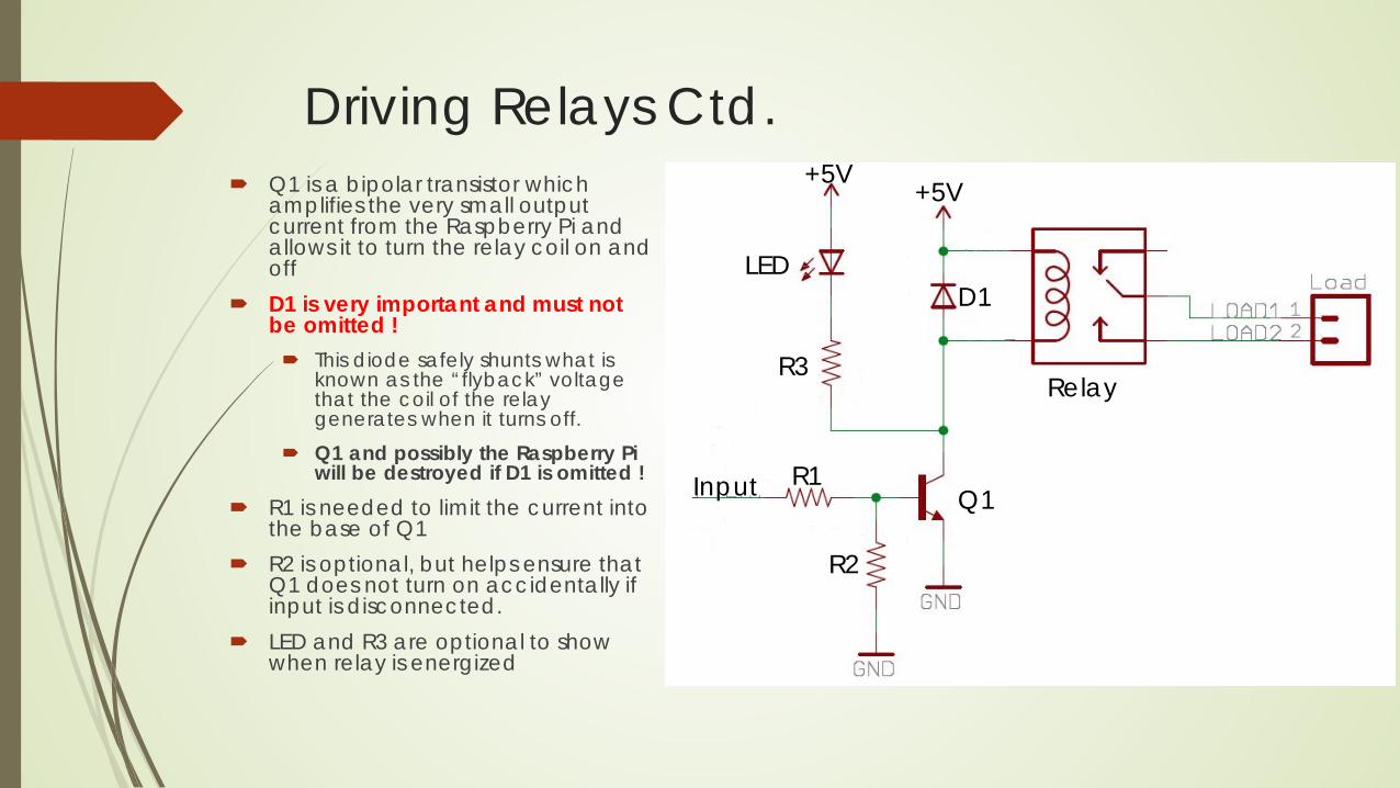
Driving Relays Ctd. Q1 is a bipolar transistor which
amplifies the very small output current from the Raspberry Pi and allows it to turn the relay coil on and off
D1 is very important and must not be omitted ! This diode safely shunts what is
known as the “flyback” voltage that the coil of the relay generates when it turns off.
Q1 and possibly the Raspberry Pi will be destroyed if D1 is omitted !
R1 is needed to limit the current into the base of Q1
R2 is optional, but helps ensure that Q1 does not turn on accidentally if input is disconnected.
LED and R3 are optional to show when relay is energized
Relay
D1LED
+5V+5V
R3
Q1R1
R2
Input
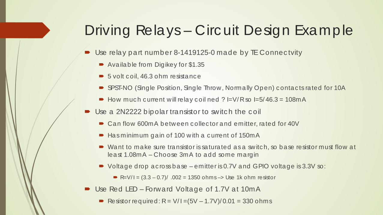
Driving Relays – Circuit Design Example Use relay part number 8-1419125-0 made by TE Connectvity
Available from Digikey for $1.35
5 volt coil, 46.3 ohm resistance
SPST-NO (Single Position, Single Throw, Normally Open) contacts rated for 10A
How much current will relay coil ned ? I=V/R so I=5/46.3 = 108mA
Use a 2N2222 bipolar transistor to switch the coil Can flow 600mA between collector and emitter, rated for 40V
Has minimum gain of 100 with a current of 150mA
Want to make sure transistor is saturated as a switch, so base resistor must flow at least 1.08mA – Choose 3mA to add some margin
Voltage drop across base – emitter is 0.7V and GPIO voltage is 3.3V so: R=V/I = (3.3 – 0.7)/ .002 = 1350 ohms –> Use 1k ohm resistor
Use Red LED – Forward Voltage of 1.7V at 10mA Resistor required: R = V/I =(5V – 1.7V)/0.01 = 330 ohms

Driving Relays – Sample Parts ListComponent Part Value Manufacturer Part Number Price (Qty1)Relay TE
Connectivity8-1419125-0 $1.35
Transistor (Q1) 2N2222A Fairchild KSP2222ABU $0.21
Diode (D1) 1N4148 Fairchild 1N4148 $.10Resistor (R1) 1k ohm, 1/8W Stackpole RNF18FTD1K00 $.10Resistor (R2) 10k ohm, 1/8W Stackpole RNF18FTD10K0 $.10LED Red Cree C556D-RFE-
CV0X0BB1$.15
Resistor (R3) 330 ohm, 1/8W Stackpole CF18JT330R $.10
All parts above available from Digikeyhttp://www.digikey.com

Solid State Relays Act like a relay, but with no moving parts
Easy to use, no moving parts, can switch very fast Use transistors and other semiconductors to perform switching Provide electrical isolation for safety similar to electromechanical relay Can switch both AC and DC depending on model Can be expensive ($15 to $50)
Most of these will still need an external transistor similar to what was used for the electromechanical relay due to the input current required to actuate them

MOSFET’s Metal Oxide Shielded Field Effect Transistor
Have 3 terminals (Gate Source and Drain)
Come in N channel and P channel types akin to NPN and PNP transistors
A voltage between the gate and the source controls the current flow between the source and drain
No current flows into the gate
Make excellent high current switches – Extremely low resistance when on
For an N-channel device, making the gate positive with respect to the source turns it on.
For a P-channel device, making the gate negative with respect to the source turns it on.
Must be cognizant of maximum gate-source voltage or part will be damaged

Make Your Own Solid State Switch Q1 is a P-channel mosfet
and is the device which will control the current through the load.
D1 is a zener diode to protect the gate of the mosfet from overvoltage
Q2 is an NPN transistor which “pulls” the gate of Q1 low with respect to its source
R1 keeps Q1 off by driving the gate high when Q2 is off.
R2 limits the current through Q2 when D1 starts to conduct.
Load

Make Your Own Solid State SwitchComponent Part Value Manufacturer Part Number Price (Qty1)MOSFET (Q1) MOSFET P-CH
55V 74A TO-220AB
Infineon IRF4905PbF $1.80
Transistor (Q1) TRANS NPN 40V 0.6A TO-92
Fairchild KSP2222ABU $0.21
Zener Diode 15V, 1/2W Fairchild 1N5245BTR $0.14Resistor (R1,R4) 49.9k ohm,
1/8WStackpole RNF18FTD49K9 $.10
Resistor R2,R3 4.75k ohm, 1/8W
Stackpole RNF18FTD4K75 $.10
All parts above available from Digikeyhttp://www.digikey.com

Isolated Solid State Switch The simple switch previously
described can be converted into an electrically isolated version by swapping Q2 for an opto-isolator as shown.
In an opto-isolator, an LED shies light onto the base of a transistor which turns it on There is no electrical
connection between the input side (LED) and the output side (transistor)
This is a very good way to provide an extra layer of protection to a Raspberry Pi and to users.
Load
U1 could be a Lite-On LTV-816Available at Digikey for $0.41 ea.
GPIO In
Ras Pi Gnd

Digital Inputs

Pushbuttons Simple pushbuttons connected to GPIO pins
You can use the built in software definable pull up / down resistors, or you can use external ones connected to either the +3.3V or GND pins
Good idea to add a 0.1uF ceramic capacitor between the GPIO pin connected to the switch and the Raspberry Pi ground for a number of benefits Mechanical switches are electrically “noisy”. The presence of the capacitor will provide
a good deal of de-bouncing and avoid spurious switch reads
The capacitor will make the GPIO pin much less susceptible to ESD damage from a static spark from a person touching the button
The capacitor is a low impedance path for electromagnetic interference, and can bypass noise to ground which could otherwise be interpreted as a button press
GPIO Pin
Ras Pi Internal or External Pull-up Resistor
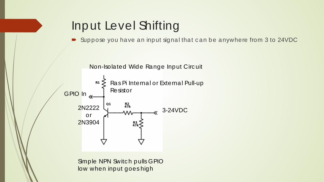
Input Level Shifting Suppose you have an input signal that can be anywhere from 3 to 24VDC
GPIO In
3-24VDC
Simple NPN Switch pulls GPIOlow when input goes high
2N2222or
2N3904
Ras Pi Internal or External Pull-up Resistor
Non-Isolated Wide Range Input Circuit
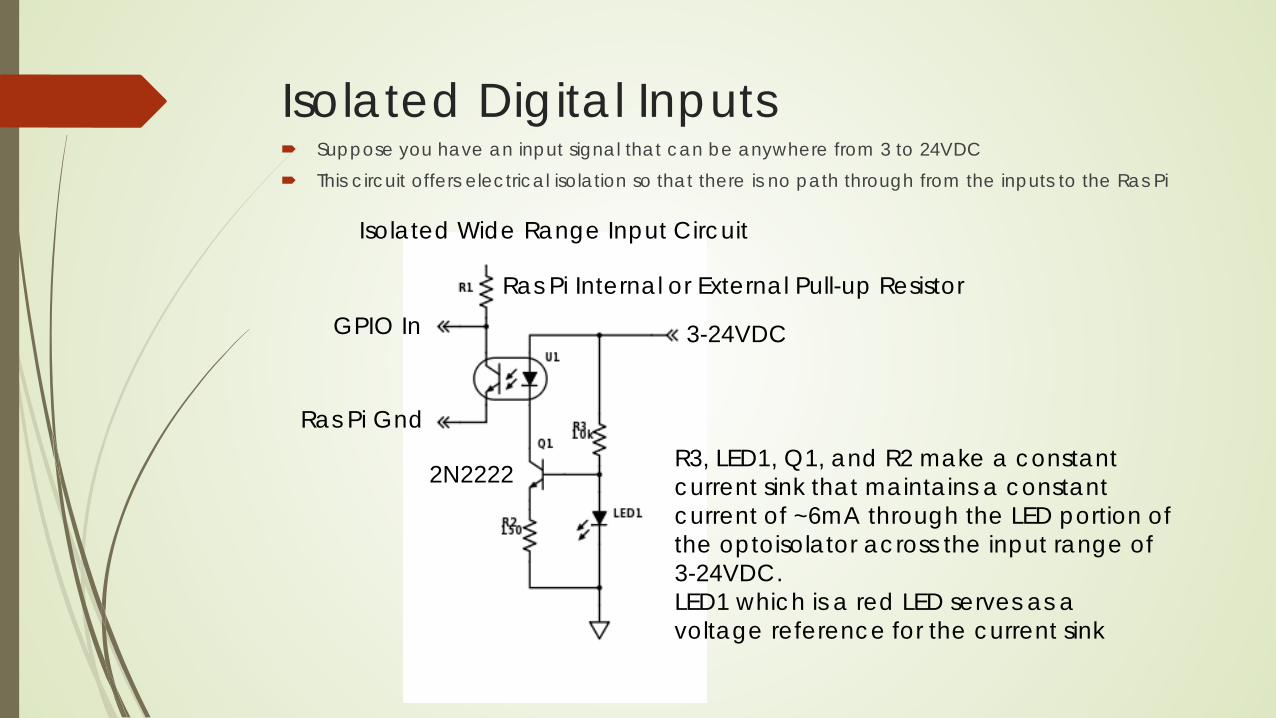
Isolated Digital Inputs Suppose you have an input signal that can be anywhere from 3 to 24VDC This circuit offers electrical isolation so that there is no path through from the inputs to the Ras Pi
GPIO In 3-24VDC
2N2222
Ras Pi Internal or External Pull-up Resistor
R3, LED1, Q1, and R2 make a constant current sink that maintains a constant current of ~6mA through the LED portion of the optoisolator across the input range of 3-24VDC.LED1 which is a red LED serves as a voltage reference for the current sink
Ras Pi Gnd
Isolated Wide Range Input Circuit

Grounding, Signal Integrity and Electrical Noise

Grounding & Power Distribution To the greatest extent possible, try to use a single point grounding scheme
when you build systems.
Use of a poor grounding scheme in systems can lead to all kinds of issues
Power Supply Widget 2 Widget 3 Widget 4
Power Supply Widget 2 Widget 3 Widget 4

Bypass Capacitors Use bypass capacitors on sensors and IC’s like A/D converters etc.
0.1uF is a common value used for local decoupling capacitors on IC’s
Provides a local reservoir of charge at the sensor or IC which can combat the effects of interconnect inductance such as wires.
Without the bypass capacitor, there can be an excessive amount of voltage ripple at the input to the device
Many IC’s and sensors will exhibit erratic behavior if decoupling capacitors are not used.
Put the decoupling capacitor as close to the input voltage pin as possible

EMI Control / Signal Integrity EMI (Electro Magnetic Interference) Using simple twisted pairs for power distribution and routing of signals can go a
long way towards controlling EMI and maintaining good signal integrity. Remember that when a current flows in a wire, it generates a magnetic field
around the wire according to the right hand rule. If we have two wires that are tightly twisted together with equal and opposite currents
in them, then the magnetic fields cancel each other.
This prevents those fields from coupling into adjacent wires !
By the same token, twisting signal wires together makes them much less susceptible to picking up noise by stray magnetic fields A magnetic field cutting across a single separated wire can generate a voltage in it.
A magnetic field cutting across a twisted pair generates equal and opposite signals that cancel
Twisted pairs are also very good for data communications like Ethernet and RS-422 because they have what is known as a characteristic impedance which allows us to avoid reflections if our circuit is designed properly.
You can make long consistent twisted pairs with a cordless drill using a simple metal hook made from coat hanger wire !

DC Motors Brush type DC motors can generate very large magnitude EMI spikes in the hundreds of volts
which can cause all kinds of problems ! Arcing brushes produce broadband (kHz to hundreds of MHz) noise
Capacitor across terminals shunts (short circuits) differential mode noise. Capacitors to motor case shunt common mode noise.
Need to control this problem at the motor before it has a chance to propagate Using a medium frequency range ferrite core with 1-3 turns of both wires through it at the motor
can provide additional suppression by making it difficult for the noise to travel down the cable. Laird LFB090050-000 available at Digikey for $0.19 each
Solder a 0.1uF ceramic capacitor across the two motor terminals
Solder a 0.1uF ceramic capacitor between each motor terminal and the case
Image credits:https://electronics.stackexchange.com/questions/19517/why-connect-capacitors-to-motor-bodyhttps://electronics.stackexchange.com/questions/239321/how-to-connect-flyback-diodes-on-a-h-bridge

Resources
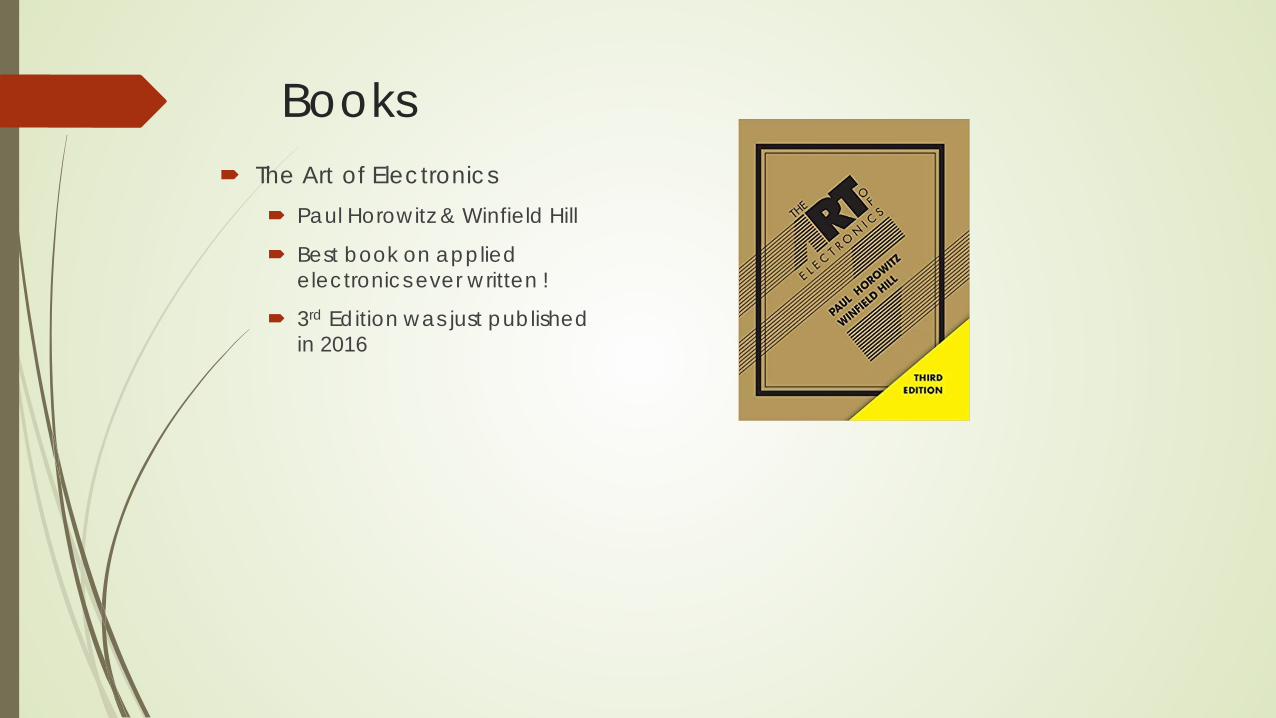
Books The Art of Electronics
Paul Horowitz & Winfield Hill
Best book on applied electronics ever written !
3rd Edition was just published in 2016
Related Documents