Nature Methods Rapid three-dimensional isotropic imaging of living cells using Bessel beam plane illumination Thomas A Planchon, Liang Gao, Daniel E Milkie, Michael W Davidson, James A Galbraith, Catherine G Galbraith & Eric Betzig Note: Supplementary Videos 1–12 are available on the Nature Methods website. Supplementary figures and tables: Supplementary Figure 1 Bessel beam cross-sectional characteristics for different maximum numerical apertures of illumination. Supplementary Figure 2 Theoretical and experimental curves of the longitudinal (y) extent of eleven Bessel beams of differing maximum and minimum numerical apertures of illumination and one Gaussian beam of low numerical aperture Supplementary Figure 3 Simplified schematic of the Bessel beam plane illumination microscope Supplementary Figure 4 Virtual and actual views of the specimen chamber Supplementary Figure 5 Optical sectioning capabilities of widefield microscopy and DSLM compared to the various modes of Bessel beam plane illumination microscopy Supplementary Figure 6 Pre-deconvolution maximum intensity projections in the xz plane for data shown in Fig. 2a- e. Supplementary Figure 7 Theoretical and experimental xz point spread functions for widefield microscopy, DSLM, and the various modes of Bessel beam plane illumination microscopy Supplementary Figure 8 Axial theoretical and experimental point spread functions for widefield, confocal, and DSLM microscopy, as well as the various modes of Bessel beam plane illumination microscopy Supplementary Figure 9 Theoretical and experimental intensity across a single Bessel beam, a swept Bessel sheet, and the overall axial PSF of the linear Bessel sheet mode Supplementary Figure 10 Tradeoff between the width of the excitation profile of a swept Bessel sheet and the longitudinal extent of the Bessel beam Supplementary Figure 11 Theoretical and experimental xz modulation transfer functions for widefield microscopy, DSLM, and the various modes of Bessel beam plane illumination microscopy Supplementary Figure 12 Theoretical and experimental xz excitation point spread functions and corresponding modulation transfer functions for the single harmonic structured illumination mode as a function of the period of the Bessel beam exposure pattern Supplementary Figure 13 Theoretical and experimental xz overall point spread functions and corresponding modulation transfer functions for the structured illumination mode with single harmonic excitation as a function of the period of the Bessel beam exposure pattern Supplementary Figure 14 Planar ordered clusters of 304 nm diameter fluorescent beads resolved by single harmonic Bessel beam structured plane illumination Nature Methods: doi.10.1038/nmeth.1586

Welcome message from author
This document is posted to help you gain knowledge. Please leave a comment to let me know what you think about it! Share it to your friends and learn new things together.
Transcript
Nature Methods
Rapid three-dimensional isotropic imaging of living cells using Bessel beam plane illumination Thomas A Planchon, Liang Gao, Daniel E Milkie, Michael W Davidson, James A Galbraith, Catherine G Galbraith & Eric Betzig Note: Supplementary Videos 1–12 are available on the Nature Methods website. Supplementary figures and tables:
Supplementary Figure 1 Bessel beam cross-sectional characteristics for different maximum numerical apertures of illumination.
Supplementary Figure 2 Theoretical and experimental curves of the longitudinal (y) extent of eleven Bessel beams of differing maximum and minimum numerical apertures of illumination and one Gaussian beam of low numerical aperture
Supplementary Figure 3 Simplified schematic of the Bessel beam plane illumination microscope
Supplementary Figure 4 Virtual and actual views of the specimen chamber
Supplementary Figure 5 Optical sectioning capabilities of widefield microscopy and DSLM compared to the various modes of Bessel beam plane illumination microscopy
Supplementary Figure 6 Pre-deconvolution maximum intensity projections in the xz plane for data shown in Fig. 2a-e.
Supplementary Figure 7 Theoretical and experimental xz point spread functions for widefield microscopy, DSLM, and the various modes of Bessel beam plane illumination microscopy
Supplementary Figure 8 Axial theoretical and experimental point spread functions for widefield, confocal, and DSLM microscopy, as well as the various modes of Bessel beam plane illumination microscopy
Supplementary Figure 9 Theoretical and experimental intensity across a single Bessel beam, a swept Bessel sheet, and the overall axial PSF of the linear Bessel sheet mode
Supplementary Figure 10 Tradeoff between the width of the excitation profile of a swept Bessel sheet and the longitudinal extent of the Bessel beam
Supplementary Figure 11 Theoretical and experimental xz modulation transfer functions for widefield microscopy, DSLM, and the various modes of Bessel beam plane illumination microscopy
Supplementary Figure 12 Theoretical and experimental xz excitation point spread functions and corresponding modulation transfer functions for the single harmonic structured illumination mode as a function of the period of the Bessel beam exposure pattern
Supplementary Figure 13 Theoretical and experimental xz overall point spread functions and corresponding modulation transfer functions for the structured illumination mode with single harmonic excitation as a function of the period of the Bessel beam exposure pattern
Supplementary Figure 14 Planar ordered clusters of 304 nm diameter fluorescent beads resolved by single harmonic Bessel beam structured plane illumination
Nature Methods: doi.10.1038/nmeth.1586
Supplementary Figure 15 Three dimensional disordered groups of 352 nm diameter fluorescent beads resolved by single harmonic Bessel beam structured plane illumination
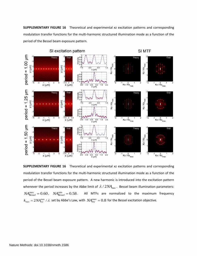
Supplementary Figure 16 Theoretical and experimental xz excitation patterns and corresponding modulation transfer functions for the multi- harmonic structured illumination mode as a function of the period of the Bessel beam exposure pattern
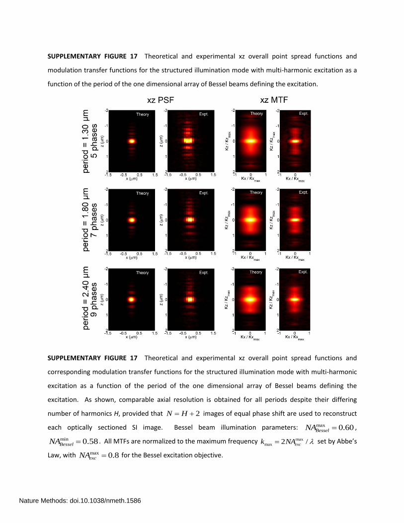
Supplementary Figure 17 Theoretical and experimental xz overall point spread functions and modulation transfer functions for the structured illumination mode with multi- harmonic excitation as a function of the period of the one-dimensional array of Bessel beams defining the excitation
Supplementary Figure 18 Image quality of antibody labeled microtubules in a fixed LLC-PK1 cell as a function of the fundamental period of excitation and number of phase-shifted images used in the structured illumination mode
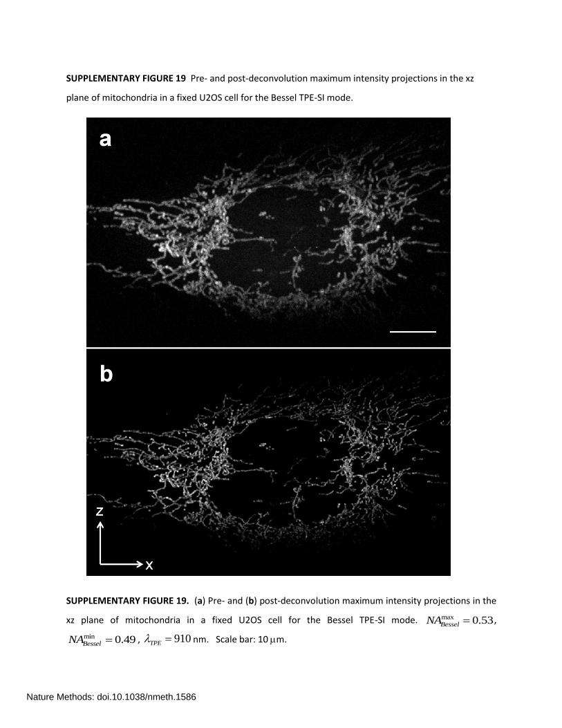
Supplementary Figure 19 Pre- and post-deconvolution maximum intensity projections in the xz plane of mitochondria in a fixed U2OS cell for the Bessel TPE-SI mode
Supplementary Figure 20 Comparison of post-deconvolution orthoslices in the xz plane of antibody-labeled microtubules in HeLa cells as obtained by confocal microscopy, DSLM, and various modes of Bessel beam plane illumination microscopy
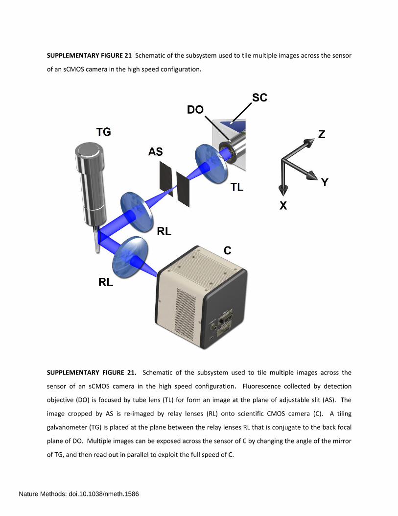
Supplementary Figure 21 Schematic of the subsystem used to tile multiple images across the sensor of an sCMOS camera in the high speed configuration
Supplementary Figure 22 Three color multi-harmonic SI mode rendering of nuclear histones, the nuclear membrane, and the actin cytoskeleton in a fixed LLC-PK1 cell
Supplementary Figure 23 Two color TPE sheet mode rendering of filamentous actin and connexin-43 in a fixed HeLa cell
Supplementary Figure 24 Schematic of the instrument control architecture
Supplementary Figure 25 Timing diagrams showing waveforms for the swept sheet mode with tiling and the SI mode.
Supplementary Figure 26 Invariance of the three-dimensional PSF across an extended volume for different modes of Bessel beam plane illumination microscopy as demonstrated in xy and xz maximum intensity projections of isolated fluorescent beads
Supplementary Table 1 Full width at half maxima (FWHM) of the axial point spread functions for various modes of Bessel beam plane illumination microscopy as compared to widefield, DSLM, and confocal microscopy
Supplementary Table 2 Acquisition parameters for all images in Figures 2–6
Supplementary Table 3 Additional parameters for Supplementary Videos 2-12
Supplementary Table 4 Parts list for Bessel beam plane illumination microscopy
Nature Methods: doi.10.1038/nmeth.1586

SUPPLEMENTARY FIGURE 1 Bessel beam cross-sectional characteristics for different maximum and
minimum numerical apertures of illumination.
SUPPLEMETARY FIGURE 1. Theoretical and experimental Bessel beam intensity cross-sections (left), z
axis linecuts (center), and modulation transfer functions (right) as functions of the maximum and
minimum numerical apertures of illumination shown at far left.
Nature Methods: doi.10.1038/nmeth.1586

SUPPLEMENTARY FIGURE 2 Theoretical and experimental curves of the longitudinal (y) extent of
eleven Bessel beams of differing maximum and minimum numerical apertures of illumination and one
Gaussian beam of low numerical aperture.
SUPPLEMENTARY FIGURE 2. Theoretical (blue) and experimental (red) curves of the longitudinal (y)
extent of eleven Bessel beams of differing maximum and minimum numerical apertures of illumination
and one Gaussian beam of low numerical aperture.
Nature Methods: doi.10.1038/nmeth.1586

SUPPLEMENTARY FIGURE 3 Simplified schematic of the Bessel beam plane illumination microscope.
SUPPLEMENTARY FIGURE 3. Simplified schematic of the Bessel beam plane illumination microscope.
Light from laser (L) is reflected from x-axis galvanometer (XG) and transmitted in turn by relay lenses
(RL) to z-axis galvanometer (ZG) and annular apodization mask (AM). XG, ZG, and AM are all at
conjugate planes, so that the Gaussian beam falling on AM does not oscillate as XG and ZG are scanned.
Similarly, AM is conjugate to the rear pupil plane of excitation objective (XO) so that the thin annular
illumination transmitted through AM produces a Bessel beam within specimen (S) that translates along x
and z without tilting. The light sheet created by scanning XG creates fluorescence at the focal plane of
detection objective (DO), which is imaged at camera (C) by tube lens (TL). Different planes within S are
imaged by translating DO with z-axis piezoelectric collar (ZP) in synchronization with the z axis motion of
the Bessel beam provided by ZG. XO, DO and S reside in medium-filled specimen chamber (SC), and epi-
objective (EO) provides a conventional view of specimen (S), for view finding purposes.
Nature Methods: doi.10.1038/nmeth.1586

SUPPLEMENTARY FIGURE 4 Virtual and actual views of the specimen chamber.
SUPPLEMENTARY FIGURE 4. Virtual and actual views of the specimen chamber. (a) Virtual view
through translucent specimen chamber (SC) showing orthogonal excitation and detection objectives
(EO, DO) and specimen holder (SH) at 45 to each. (b) Actual view through epi-port (EP) after removal of
epi-objective, showing converging and then expanding light cone (LC) and region of Bessel beam
excitation (BB) near the focus, as well water surface (WS) within the chamber.
Nature Methods: doi.10.1038/nmeth.1586

SUPPLEMENTARY FIGURE 5 Optical sectioning capabilities widefield microscopy and DSLM compared
to the various modes of Bessel beam plane illumination microscopy.
SUPPLEMENTARY FIGURE 5. Optical sectioning capabilities of widefield microscopy and digital scanned
light sheet microscopy (DSLM, 0.2excNA ) compared to that of various modes of Bessel beam plane
illumination microscopy ( max 0.53excNA ), at three different planes through mitochondria-labeled fixed
LLC-PK1 cells. The illuminated region shifts in y at different z planes, since the sample is mounted at 45
to the y and z axes. Scale bar: 10 m.
Nature Methods: doi.10.1038/nmeth.1586
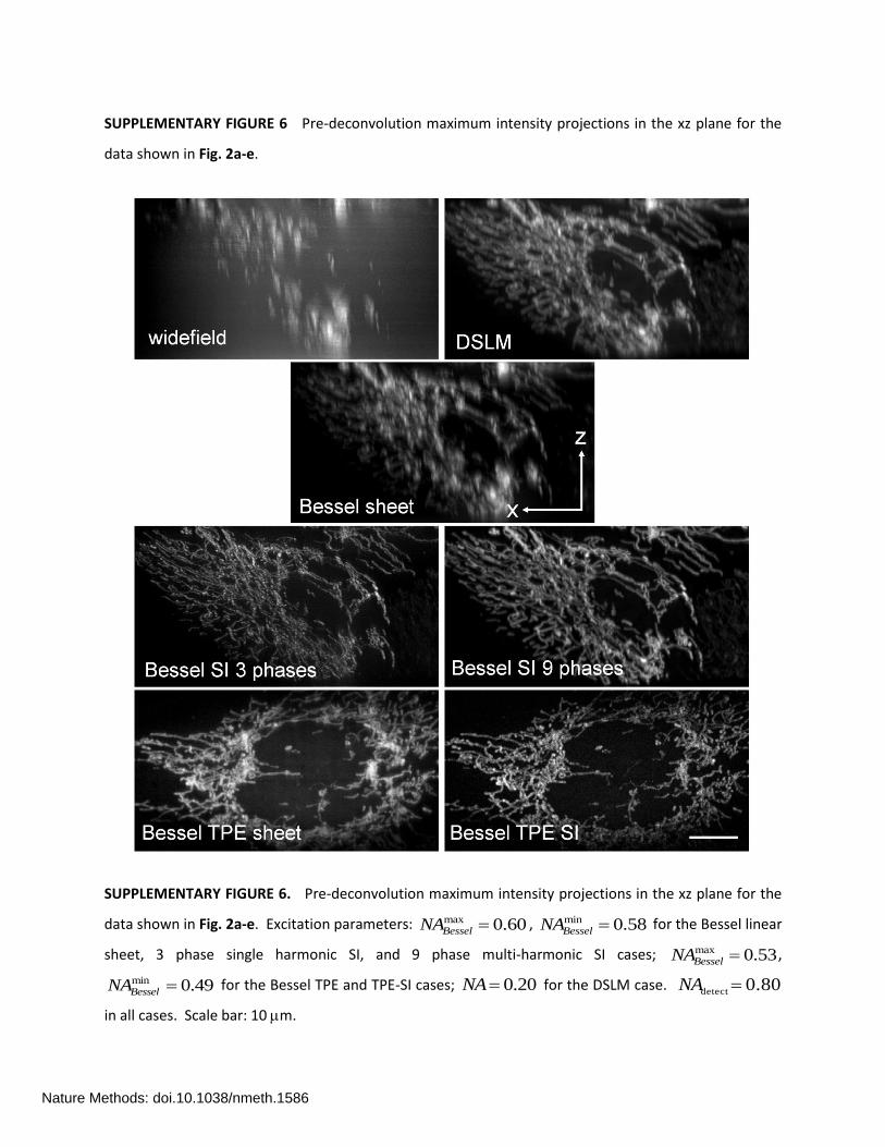
SUPPLEMENTARY FIGURE 6 Pre-deconvolution maximum intensity projections in the xz plane for the
data shown in Fig. 2a-e.
SUPPLEMENTARY FIGURE 6. Pre-deconvolution maximum intensity projections in the xz plane for the
data shown in Fig. 2a-e. Excitation parameters: max 0.60BesselNA , min 0.58BesselNA for the Bessel linear
sheet, 3 phase single harmonic SI, and 9 phase multi-harmonic SI cases; max 0.53BesselNA ,
min 0.49BesselNA for the Bessel TPE and TPE-SI cases; 0.20NA for the DSLM case.
detect 0.80NA
in all cases. Scale bar: 10 m.
Nature Methods: doi.10.1038/nmeth.1586
SUPPLEMENTARY FIGURE 7 Theoretical and experimental xz point spread functions for widefield
microscopy, DSLM, and the various modes of Bessel beam plane illumination microscopy.
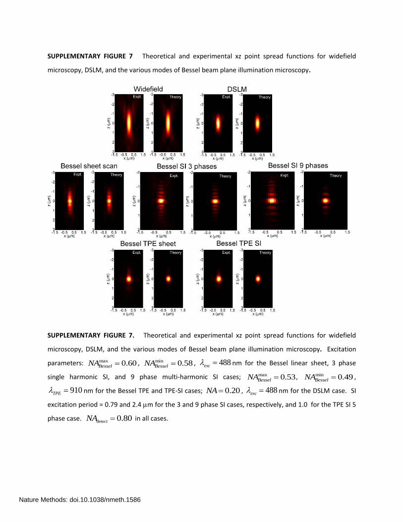
SUPPLEMENTARY FIGURE 7. Theoretical and experimental xz point spread functions for widefield
microscopy, DSLM, and the various modes of Bessel beam plane illumination microscopy. Excitation
parameters: max 0.60BesselNA , min 0.58BesselNA , 488exc nm for the Bessel linear sheet, 3 phase
single harmonic SI, and 9 phase multi-harmonic SI cases; max 0.53BesselNA , min 0.49BesselNA ,
910TPE nm for the Bessel TPE and TPE-SI cases; 0.20NA , 488exc nm for the DSLM case. SI
excitation period = 0.79 and 2.4 m for the 3 and 9 phase SI cases, respectively, and 1.0 for the TPE SI 5
phase case. detect 0.80NA in all cases.
Nature Methods: doi.10.1038/nmeth.1586
SUPPLEMENTARY FIGURE 8 Axial theoretical and experimental point spread functions for widefield,
confocal, and DSLM microscopy, as well as the various modes of Bessel beam plane illumination
microscopy.
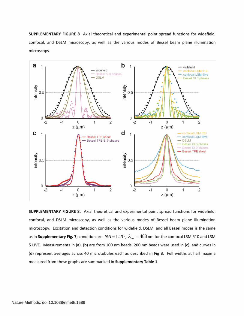
SUPPLEMENTARY FIGURE 8. Axial theoretical and experimental point spread functions for widefield,
confocal, and DSLM microscopy, as well as the various modes of Bessel beam plane illumination
microscopy. Excitation and detection conditions for widefield, DSLM, and all Bessel modes is the same
as in Supplementary Fig. 7; condition are 1.20NA , 488exc nm for the confocal LSM 510 and LSM
5 LIVE. Measurements in (a), (b) are from 100 nm beads, 200 nm beads were used in (c), and curves in
(d) represent averages across 40 microtubules each as described in Fig 3. Full widths at half maxima
measured from these graphs are summarized in Supplementary Table 1.
Nature Methods: doi.10.1038/nmeth.1586
SUPPLEMENTARY FIGURE 9 Theoretical and experimental intensity across a single Bessel beam, a
swept Bessel sheet, and the overall axial PSF of the linear Bessel sheet mode
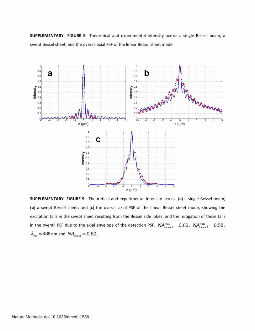
SUPPLEMENTARY FIGURE 9. Theoretical and experimental intensity across: (a) a single Bessel beam;
(b) a swept Bessel sheet; and (c) the overall axial PSF of the linear Bessel sheet mode, showing the
excitation tails in the swept sheet resulting from the Bessel side lobes, and the mitigation of these tails
in the overall PSF due to the axial envelope of the detection PSF. max 0.60BesselNA , min 0.58BesselNA ,
488exc nm and detect 0.80NA .
Nature Methods: doi.10.1038/nmeth.1586

SUPPLEMENTARY FIGURE 10 Tradeoff between the width of the excitation profile of a swept Bessel
sheet and the longitudinal extent of the Bessel beam.
SUPPLEMENTARY FIGURE 10. Tradeoff between (a) the width of the excitation profile of a swept
Bessel sheet and (b) the longitudinal extent of the Bessel beam. Beam illumination parameters:
max 0.60BesselNA in all cases, min 0.58BesselNA (blue), 0.56 (green), 0.52 (red), 0.45 (purple), 0.30
(olive), and 0.00 (cyan, Gaussian beam case).
Nature Methods: doi.10.1038/nmeth.1586

SUPPLEMENTARY FIGURE 11 Theoretical and experimental xz modulation transfer functions for
widefield microscopy, DSLM, and the various modes of Bessel beam plane illumination microscopy.
SUPPLEMENTARY FIGURE 11. Theoretical and experimental xz modulation transfer functions for
widefield microscopy, DSLM, and the various modes of Bessel beam plane illumination microscopy,
calculated from the corresponding point spread functions in Supplementary Fig. 7. All MTFs are
normalized to the maximum frequency max
max 2 /exc exck NA or max
max 2 / / 2exc TPEk NA set by
Abbe’s Law, with max 0.8excNA for the Bessel excitation objective.
Nature Methods: doi.10.1038/nmeth.1586
SUPPLEMENTARY FIGURE 12 Theoretical and experimental xz excitation patterns and corresponding
modulation transfer functions for the single harmonic structured illumination mode as a function of the
period of the Bessel beam exposure pattern.
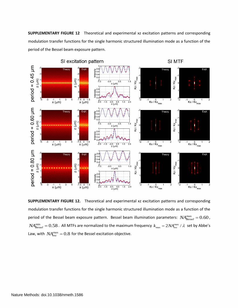
SUPPLEMENTARY FIGURE 12. Theoretical and experimental xz excitation patterns and corresponding
modulation transfer functions for the single harmonic structured illumination mode as a function of the
period of the Bessel beam exposure pattern. Bessel beam illumination parameters: max 0.60BesselNA ,
min 0.58BesselNA . All MTFs are normalized to the maximum frequency max
max 2 /exck NA set by Abbe’s
Law, with max 0.8excNA for the Bessel excitation objective.
Nature Methods: doi.10.1038/nmeth.1586

SUPPLEMENTARY FIGURE 13 Theoretical and experimental xz overall point spread functions and
corresponding modulation transfer functions for the structured illumination mode with single harmonic
excitation as a function of the period of the the Bessel beam exposure pattern.
SUPPLEMENTARY FIGURE 13 Theoretical and experimental xz overall point spread functions and
corresponding modulation transfer functions for the structured illumination mode with single harmonic
excitation as a function of the period of the the Bessel beam exposure pattern. The axial resolution
improves as the excitation period increases from the minimum of max/ 2 BesselNA allowed by diffraction
(0.407 m for 488 nm, max 0.6BesselNA in this example) up to the maximum of max/ BesselNA for
which the excitation pattern still contains only a single harmonic in the scan direction. Furthermore, as
the period increases, the axial resolution increasingly exceeds the classical diffraction limit (
max/ 0.75z zk k here, since all MTFs are normalized to max max2 /z exck NA for the max 0.8excNA Bessel
excitation objective).
Nature Methods: doi.10.1038/nmeth.1586

SUPPLEMENTARY FIGURE 14 Planar ordered clusters of 304 nm diameter fluorescent beads resolved
by single harmonic Bessel beam structured plane illumination.
SUPPLEMENTARY FIGURE 14 Planar ordered clusters of 304 nm diameter fluorescent beads resolved
by single harmonic Bessel beam structured plane illumination. Top row: xy (left) and xz (right) maximum
intensity projections and volume rendering (center) in the x sample plane at 45 to the y and z
microscope coordinate axes, after filtering to remove noise beyond the Abbe limit in xy, and twice the
Abbe limit in z. Middle row: xy (left), x (center), and xz (right) orthoslices through the 3D MTF
calculated from raw 3D image stack. Green ovals represent the Abbe limit in xyz space, and blue ovals
represent an extended limit based on the Abbe limit in xy (0.32 m for det 0.52 m, det 0.8NA ),
and twice the Abbe limit in z (0.474 m for 0.488exc m, max 0.515BesselNA ). Bottom row:
corresponding views after deconvolution using a theoretical PSF. Scale bar at bottom center: 2 m.
Nature Methods: doi.10.1038/nmeth.1586

SUPPLEMENTARY FIGURE 15 Three dimensional disordered groups of 352 nm diameter fluorescent
beads resolved by single harmonic Bessel beam structured plane illumination.
SUPPLEMENTARY FIGURE 15 Three dimensional disordered groups of 352 nm diameter fluorescent
beads resolved by single harmonic Bessel beam structured plane illumination. Top row: volume
renderings as viewed nearly parallel to the sample plane for both the original and deconvolved data
(scale bar: 2 m). Bottom row: Orthoslices through the 3D MTF calculated from the 3D image stack.
Imaging conditions and figure descriptions are identical to Supplementary Fig. XX.
Nature Methods: doi.10.1038/nmeth.1586
SUPPLEMENTARY FIGURE 16 Theoretical and experimental xz excitation patterns and corresponding
modulation transfer functions for the multi-harmonic structured illumination mode as a function of the
period of the Bessel beam exposure pattern.
SUPPLEMENTARY FIGURE 16 Theoretical and experimental xz excitation patterns and corresponding
modulation transfer functions for the multi-harmonic structured illumination mode as a function of the
period of the Bessel beam exposure pattern. A new harmonic is introduced into the excitation pattern
whenever the period increases by the Abbe limit of max/ 2NA . Bessel beam illumination parameters:
max 0.60BesselNA , min 0.58BesselNA . All MTFs are normalized to the maximum frequency
max
max 2 /exck NA set by Abbe’s Law, with max 0.8excNA for the Bessel excitation objective.
Nature Methods: doi.10.1038/nmeth.1586
SUPPLEMENTARY FIGURE 17 Theoretical and experimental xz overall point spread functions and
modulation transfer functions for the structured illumination mode with multi-harmonic excitation as a
function of the period of the one dimensional array of Bessel beams defining the excitation.
SUPPLEMENTARY FIGURE 17 Theoretical and experimental xz overall point spread functions and
corresponding modulation transfer functions for the structured illumination mode with multi-harmonic
excitation as a function of the period of the one dimensional array of Bessel beams defining the
excitation. As shown, comparable axial resolution is obtained for all periods despite their differing
number of harmonics H, provided that 2N H images of equal phase shift are used to reconstruct
each optically sectioned SI image. Bessel beam illumination parameters: max 0.60BesselNA ,
min 0.58BesselNA . All MTFs are normalized to the maximum frequency max
max 2 /exck NA set by Abbe’s
Law, with max 0.8excNA for the Bessel excitation objective.
Nature Methods: doi.10.1038/nmeth.1586

SUPPLEMENTARY FIGURE 18 Image quality of antibody labeled microtubules in a fixed LLC-PK1 cell as a
function of the fundamental period of excitation and number of phase-shifted images used in the
structured illumination mode.
SUPPLEMENTARY FIGURE 18. Image quality of antibody labeled microtubules in a fixed LLC-PK1 cell as
a function of the fundamental period of excitation and number of phase-shifted images used in the
structured illumination mode. All are maximum intensity projections normalized to the same scale. The
SI signal and signal-to-noise ratio increases with an increasing number N of phase shifted images, even
though the total integration time across all N images is the same in each case. Parameters:
max 0.52BesselNA , min 0.50BesselNA , 0.80detectNA .
Nature Methods: doi.10.1038/nmeth.1586
SUPPLEMENTARY FIGURE 19 Pre- and post-deconvolution maximum intensity projections in the xz
plane of mitochondria in a fixed U2OS cell for the Bessel TPE-SI mode.
SUPPLEMENTARY FIGURE 19. (a) Pre- and (b) post-deconvolution maximum intensity projections in the
xz plane of mitochondria in a fixed U2OS cell for the Bessel TPE-SI mode. max 0.53BesselNA ,
min 0.49BesselNA , 910TPE nm. Scale bar: 10 m.
Nature Methods: doi.10.1038/nmeth.1586

SUPPLEMENTARY FIGURE 20 Comparison of post-deconvolution orthoslices in the xz plane of
antibody-labeled microtubules in HeLa cells as obtained by confocal microscopy, DSLM, and various
modes of Bessel beam plane illumination microscopy.
SUPPLEMENTARY FIGURE 20. Comparison of post-deconvolution orthoslices in the xz plane of
antibody-labeled microtubules in HeLa cells as obtained by confocal microscopy, DSLM, and various
modes of Bessel beam plane illumination microscopy: (a) point scanning confocal microscopy (Zeiss LSM
510, 40x/1.20 W objective, 1 Airy unit filtering); (b) line scanning confocal microscopy (Zeiss LSM 5 Live,
same objective and filtering); (c) DSLM ( 0.20excNA ); (d) Bessel beam single harmonic SI mode (3
phases, 0.9 m period, max 0.52BesselNA , min 0.50BesselNA ); (e) Bessel beam multi-harmonic SI mode (9
phases, 2.7 m period max 0.52BesselNA , min 0.50BesselNA ); (f) Bessel beam two-photon swept sheet
mode ( max 0.53BesselNA , min 0.49BesselNA ).
Nature Methods: doi.10.1038/nmeth.1586
SUPPLEMENTARY FIGURE 21 Schematic of the subsystem used to tile multiple images across the sensor
of an sCMOS camera in the high speed configuration.
SUPPLEMENTARY FIGURE 21. Schematic of the subsystem used to tile multiple images across the
sensor of an sCMOS camera in the high speed configuration. Fluorescence collected by detection
objective (DO) is focused by tube lens (TL) for form an image at the plane of adjustable slit (AS). The
image cropped by AS is re-imaged by relay lenses (RL) onto scientific CMOS camera (C). A tiling
galvanometer (TG) is placed at the plane between the relay lenses RL that is conjugate to the back focal
plane of DO. Multiple images can be exposed across the sensor of C by changing the angle of the mirror
of TG, and then read out in parallel to exploit the full speed of C.
Nature Methods: doi.10.1038/nmeth.1586
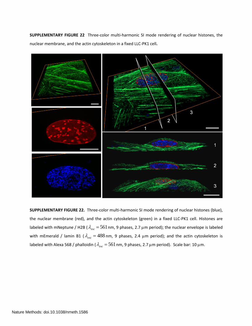
SUPPLEMENTARY FIGURE 22 Three-color multi-harmonic SI mode rendering of nuclear histones, the
nuclear membrane, and the actin cytoskeleton in a fixed LLC-PK1 cell.
SUPPLEMENTARY FIGURE 22. Three-color multi-harmonic SI mode rendering of nuclear histones (blue),
the nuclear membrane (red), and the actin cytoskeleton (green) in a fixed LLC-PK1 cell. Histones are
labeled with mNeptune / H2B ( 561exc nm, 9 phases, 2.7 m period); the nuclear envelope is labeled
with mEmerald / lamin B1 ( 488exc nm, 9 phases, 2.4 m period); and the actin cytoskeleton is
labeled with Alexa 568 / phalloidin ( 561exc nm, 9 phases, 2.7 m period). Scale bar: 10 m.
Nature Methods: doi.10.1038/nmeth.1586

SUPPLEMENTARY FIGURE 23 Two-color TPE sheet mode rendering of filamentous actin and connexin-
43 in a fixed HeLa cell.
SUPPLEMENTARY FIGURE 23. Two-color TPE sheet mode rendering of filamentous actin (orange) and
connexin-43 (green) in a fixed HeLa cell. Gap junctions are labeled with mCerulean3 / connexin-43 (
858TPE nm), and filamentous actin is labeled with mEmerald / Lifeact (orange, 910TPE nm).
Nature Methods: doi.10.1038/nmeth.1586
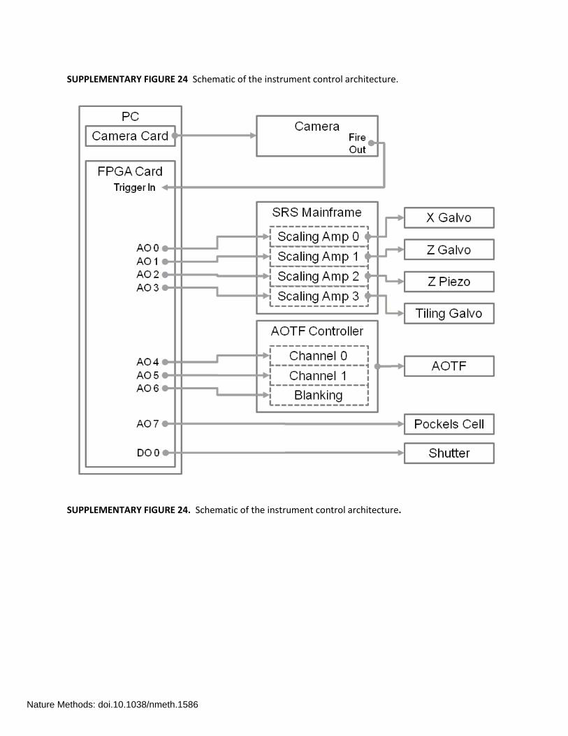
SUPPLEMENTARY FIGURE 24 Schematic of the instrument control architecture.
SUPPLEMENTARY FIGURE 24. Schematic of the instrument control architecture.
Nature Methods: doi.10.1038/nmeth.1586

SUPPLEMENTARY FIGURE 25 Timing diagrams showing waveforms for the swept sheet mode with tiling
and the SI mode.
SUPPLEMENTARY FIGURE 25. Timing diagrams showing waveforms for (a) the swept sheet mode with
tiling and (b) the SI mode.
Nature Methods: doi.10.1038/nmeth.1586
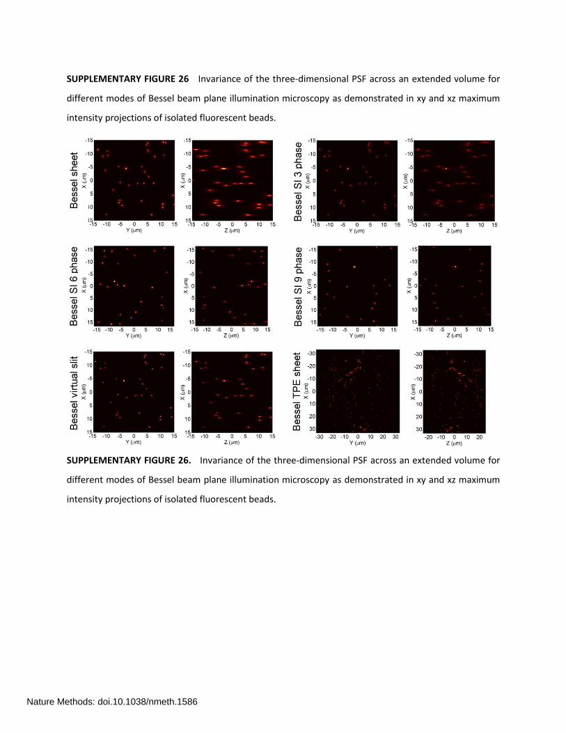
SUPPLEMENTARY FIGURE 26 Invariance of the three-dimensional PSF across an extended volume for
different modes of Bessel beam plane illumination microscopy as demonstrated in xy and xz maximum
intensity projections of isolated fluorescent beads.
SUPPLEMENTARY FIGURE 26. Invariance of the three-dimensional PSF across an extended volume for
different modes of Bessel beam plane illumination microscopy as demonstrated in xy and xz maximum
intensity projections of isolated fluorescent beads.
Nature Methods: doi.10.1038/nmeth.1586
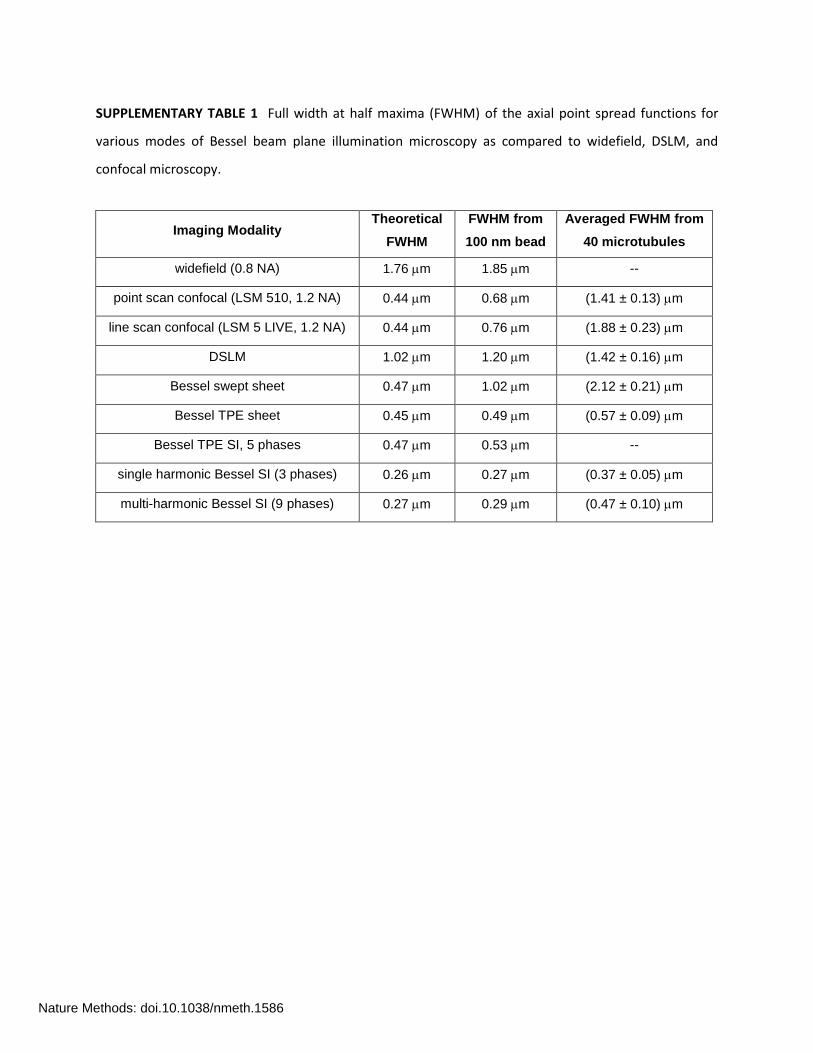
SUPPLEMENTARY TABLE 1 Full width at half maxima (FWHM) of the axial point spread functions for
various modes of Bessel beam plane illumination microscopy as compared to widefield, DSLM, and
confocal microscopy.
Imaging Modality Theoretical
FWHM
FWHM from
100 nm bead
Averaged FWHM from
40 microtubules
widefield (0.8 NA) 1.76 m 1.85 m --
point scan confocal (LSM 510, 1.2 NA) 0.44 m 0.68 m (1.41 ± 0.13) m
line scan confocal (LSM 5 LIVE, 1.2 NA) 0.44 m 0.76 m (1.88 ± 0.23) m
DSLM 1.02 m 1.20 m (1.42 ± 0.16) m
Bessel swept sheet 0.47 m 1.02 m (2.12 ± 0.21) m
Bessel TPE sheet 0.45 m 0.49 m (0.57 ± 0.09) m
Bessel TPE SI, 5 phases 0.47 m 0.53 m --
single harmonic Bessel SI (3 phases) 0.26 m 0.27 m (0.37 ± 0.05) m
multi-harmonic Bessel SI (9 phases) 0.27 m 0.29 m (0.47 ± 0.10) m
Nature Methods: doi.10.1038/nmeth.1586
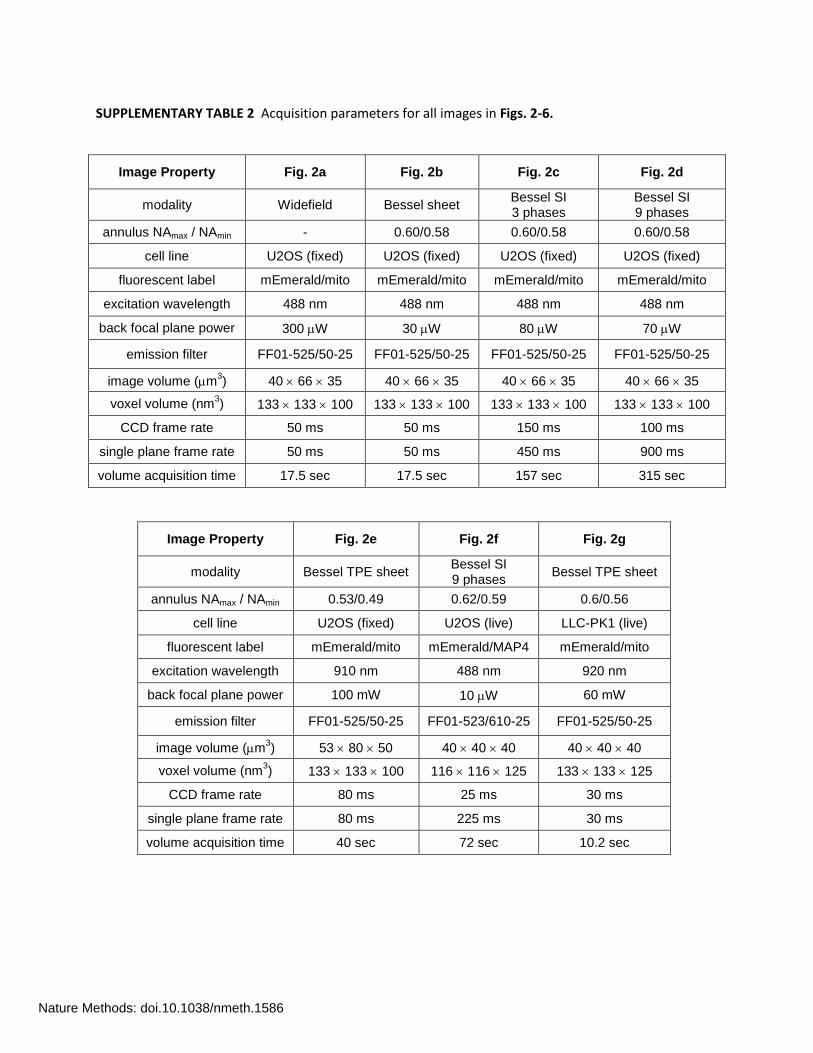
SUPPLEMENTARY TABLE 2 Acquisition parameters for all images in Figs. 2-6.
Image Property Fig. 2a Fig. 2b Fig. 2c Fig. 2d
modality Widefield Bessel sheet Bessel SI 3 phases
Bessel SI 9 phases
annulus NAmax / NAmin - 0.60/0.58 0.60/0.58 0.60/0.58
cell line U2OS (fixed) U2OS (fixed) U2OS (fixed) U2OS (fixed)
fluorescent label mEmerald/mito mEmerald/mito mEmerald/mito mEmerald/mito
excitation wavelength 488 nm 488 nm 488 nm 488 nm
back focal plane power 300 W 30 W 80 W 70 W
emission filter FF01-525/50-25 FF01-525/50-25 FF01-525/50-25 FF01-525/50-25
image volume (m3) 40 66 35 40 66 35 40 66 35 40 66 35
voxel volume (nm3) 133 133 100 133 133 100 133 133 100 133 133 100
CCD frame rate 50 ms 50 ms 150 ms 100 ms
single plane frame rate 50 ms 50 ms 450 ms 900 ms
volume acquisition time 17.5 sec 17.5 sec 157 sec 315 sec
Image Property Fig. 2e Fig. 2f Fig. 2g
modality Bessel TPE sheet Bessel SI 9 phases
Bessel TPE sheet
annulus NAmax / NAmin 0.53/0.49 0.62/0.59 0.6/0.56
cell line U2OS (fixed) U2OS (live) LLC-PK1 (live)
fluorescent label mEmerald/mito mEmerald/MAP4 mEmerald/mito
excitation wavelength 910 nm 488 nm 920 nm
back focal plane power 100 mW 10 W 60 mW
emission filter FF01-525/50-25 FF01-523/610-25 FF01-525/50-25
image volume (m3) 53 80 50 40 40 40 40 40 40
voxel volume (nm3) 133 133 100 116 116 125 133 133 125
CCD frame rate 80 ms 25 ms 30 ms
single plane frame rate 80 ms 225 ms 30 ms
volume acquisition time 40 sec 72 sec 10.2 sec
Nature Methods: doi.10.1038/nmeth.1586
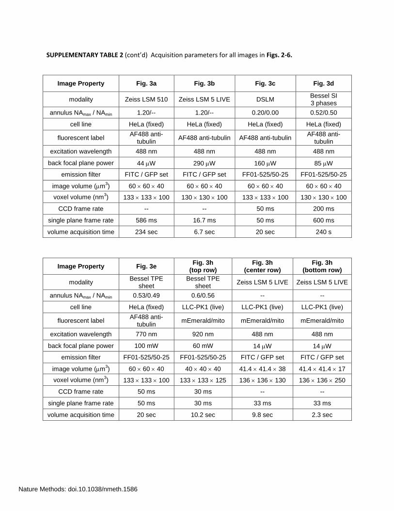
SUPPLEMENTARY TABLE 2 (cont’d) Acquisition parameters for all images in Figs. 2-6.
Image Property Fig. 3a Fig. 3b Fig. 3c Fig. 3d
modality Zeiss LSM 510 Zeiss LSM 5 LIVE DSLM Bessel SI 3 phases
annulus NAmax / NAmin 1.20/-- 1.20/-- 0.20/0.00 0.52/0.50
cell line HeLa (fixed) HeLa (fixed) HeLa (fixed) HeLa (fixed)
fluorescent label AF488 anti-
tubulin AF488 anti-tubulin AF488 anti-tubulin
AF488 anti-tubulin
excitation wavelength 488 nm 488 nm 488 nm 488 nm
back focal plane power 44 W 290 W 160 W 85 W
emission filter FITC / GFP set FITC / GFP set FF01-525/50-25 FF01-525/50-25
image volume (m3) 60 60 40 60 60 40 60 60 40 60 60 40
voxel volume (nm3) 133 133 100 130 130 100 133 133 100 130 130 100
CCD frame rate -- -- 50 ms 200 ms
single plane frame rate 586 ms 16.7 ms 50 ms 600 ms
volume acquisition time 234 sec 6.7 sec 20 sec 240 s
Image Property Fig. 3e Fig. 3h
(top row) Fig. 3h
(center row) Fig. 3h
(bottom row)
modality Bessel TPE
sheet Bessel TPE
sheet Zeiss LSM 5 LIVE Zeiss LSM 5 LIVE
annulus NAmax / NAmin 0.53/0.49 0.6/0.56 -- --
cell line HeLa (fixed) LLC-PK1 (live) LLC-PK1 (live) LLC-PK1 (live)
fluorescent label AF488 anti-
tubulin mEmerald/mito mEmerald/mito mEmerald/mito
excitation wavelength 770 nm 920 nm 488 nm 488 nm
back focal plane power 100 mW 60 mW 14 W 14 W
emission filter FF01-525/50-25 FF01-525/50-25 FITC / GFP set FITC / GFP set
image volume (m3) 60 60 40 40 40 40 41.4 41.4 38 41.4 41.4 17
voxel volume (nm3) 133 133 100 133 133 125 136 136 130 136 136 250
CCD frame rate 50 ms 30 ms -- --
single plane frame rate 50 ms 30 ms 33 ms 33 ms
volume acquisition time 20 sec 10.2 sec 9.8 sec 2.3 sec
Nature Methods: doi.10.1038/nmeth.1586

SUPPLEMENTARY TABLE 2 (cont’d) Acquisition parameters for all images in Figs. 2-6.
Image Property Fig. 4a Fig. 4b Fig. 4c Fig. 5
modality Bessel SI 9 Phases
Bessel TPE sheet
Bessel TPE sheet Bessel TPE
sheet
annulus NAmax / NAmin 0.62/0.59 0.62/0.57 0.62/0.57 0.62/0.57
cell line U2OS (live) HeLa (live) HeLa (live) LLC-PK1 (live)
fluorescent label tdTomato/ER mEmerald/Lifeact mEmerald/C-src mEmerald/H2B
excitation wavelength 561 nm 920 nm 920 nm 920 nm
back focal plane power 5 W 200 mW 200 mW 220 mW
emission filter FF01-525/50-25 FF01-525/50-25 FF01-525/50-25 FF01-525/50-25
image volume (m3) 40 40 40 30 30 30 48 46 42 33 33 30
voxel volume (nm3) 144 144 125 116 116 150 116 116 150 116 116 150
CCD frame rate 17 ms 17 ms 37 ms 26 ms
single plane frame rate 153 ms 17 ms 37 ms 5.2 ms
volume acquisition time 50 sec 3.5 sec 10.2 sec 1.05 sec
Image Property Fig. 6a Fig. 6b Sup Fig. 22 Sup Fig. 23
modality Bessel SI 9 phases
Bessel TPE sheet
Bessel SI 9 phases
Bessel TPE sheet
annulus NAmax / NAmin 0.62/0.59 0.6/0.56 0.60/0.58 0.53/0.49
cell line U2OS (live) LLC-PK1 (live) LLC-PK1 (fixed) HeLa (fixed)
fluorescent label mEmerald/MAP4 mEmerald/H2B
mEmerald/H2B mEmerald/Mann2
mEmerald/lamin B1 AF568 phalloidin mNeptune/H2B
mCerulean3/ Cx43 mEmerald/lifeact
excitation wavelength 488/561nm 920 nm 488/561/561 nm 860/910 nm
back focal plane power 10/5 W 50 mW 60/60/150 W 110/100 mW
emission filter FF01-523/610-25 FF01-525/50-25 FF01-525/50-25 FF01-593/40-25 LP02-633RS-25
FF01-470/100-25 FF01-525/50-25
image volume (m3) 40 40 40 40 40 40 53 67 50 53 80 50
voxel volume (nm3) 116 116 125 133 133 125 133 133 100 133 133 100
CCD frame rate 25 ms 33 ms 100 ms 80 ms
single plane frame rate 225 ms 33 ms 900 ms 80 ms
volume acquisition time
72 sec/color 10.7 sec 450 sec/color 40 sec/color
Nature Methods: doi.10.1038/nmeth.1586
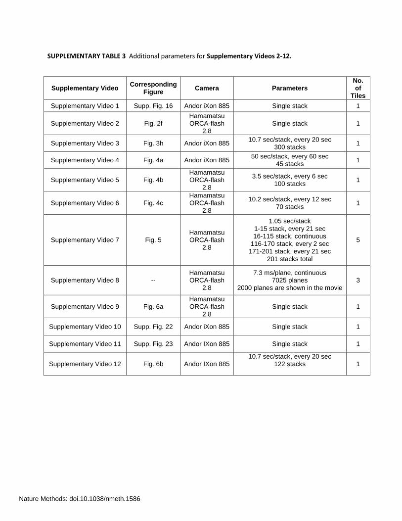
SUPPLEMENTARY TABLE 3 Additional parameters for Supplementary Videos 2-12.
Supplementary Video Corresponding
Figure Camera Parameters
No. of
Tiles
Supplementary Video 1 Supp. Fig. 16 Andor iXon 885 Single stack 1
Supplementary Video 2 Fig. 2f Hamamatsu ORCA-flash
2.8 Single stack 1
Supplementary Video 3 Fig. 3h Andor iXon 885 10.7 sec/stack, every 20 sec
300 stacks 1
Supplementary Video 4 Fig. 4a Andor iXon 885 50 sec/stack, every 60 sec
45 stacks 1
Supplementary Video 5 Fig. 4b Hamamatsu ORCA-flash
2.8
3.5 sec/stack, every 6 sec 100 stacks
1
Supplementary Video 6 Fig. 4c Hamamatsu ORCA-flash
2.8
10.2 sec/stack, every 12 sec 70 stacks
1
Supplementary Video 7 Fig. 5 Hamamatsu ORCA-flash
2.8
1.05 sec/stack 1-15 stack, every 21 sec 16-115 stack, continuous
116-170 stack, every 2 sec 171-201 stack, every 21 sec
201 stacks total
5
Supplementary Video 8 -- Hamamatsu ORCA-flash
2.8
7.3 ms/plane, continuous 7025 planes
2000 planes are shown in the movie 3
Supplementary Video 9 Fig. 6a Hamamatsu ORCA-flash
2.8 Single stack 1
Supplementary Video 10 Supp. Fig. 22 Andor iXon 885 Single stack 1
Supplementary Video 11 Supp. Fig. 23 Andor IXon 885 Single stack 1
Supplementary Video 12 Fig. 6b Andor IXon 885 10.7 sec/stack, every 20 sec
122 stacks
1
Nature Methods: doi.10.1038/nmeth.1586
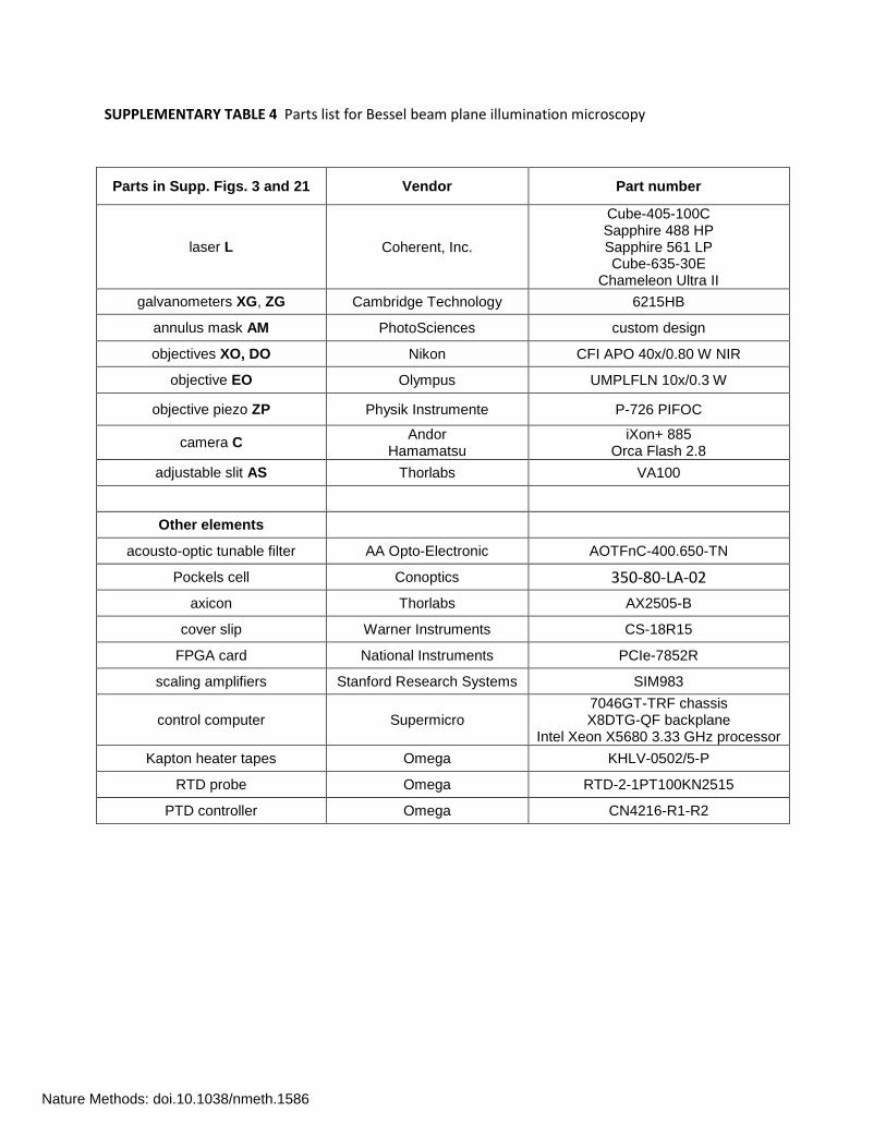
SUPPLEMENTARY TABLE 4 Parts list for Bessel beam plane illumination microscopy
Parts in Supp. Figs. 3 and 21 Vendor Part number
laser L Coherent, Inc.
Cube-405-100C Sapphire 488 HP Sapphire 561 LP Cube-635-30E
Chameleon Ultra II
galvanometers XG, ZG Cambridge Technology 6215HB
annulus mask AM PhotoSciences custom design
objectives XO, DO Nikon CFI APO 40x/0.80 W NIR
objective EO Olympus UMPLFLN 10x/0.3 W
objective piezo ZP Physik Instrumente P-726 PIFOC
camera C Andor
Hamamatsu iXon+ 885
Orca Flash 2.8
adjustable slit AS Thorlabs VA100
Other elements
acousto-optic tunable filter AA Opto-Electronic AOTFnC-400.650-TN
Pockels cell Conoptics 350-80-LA-02
axicon Thorlabs AX2505-B
cover slip Warner Instruments CS-18R15
FPGA card National Instruments PCIe-7852R
scaling amplifiers Stanford Research Systems SIM983
control computer Supermicro 7046GT-TRF chassis X8DTG-QF backplane
Intel Xeon X5680 3.33 GHz processor
Kapton heater tapes Omega KHLV-0502/5-P
RTD probe Omega RTD-2-1PT100KN2515
PTD controller Omega CN4216-R1-R2
Nature Methods: doi.10.1038/nmeth.1586
Related Documents