ARTICLE Rapid synchronized fabrication of vascularized thermosets and composites Mayank Garg 1,2 , Jia En Aw 1,3 , Xiang Zhang 6 , Polette J. Centellas 1,3 , Leon M. Dean 1,2 , Evan M. Lloyd 1,4 , Ian D. Robertson 1,5 , Yiqiao Liu 2 , Mostafa Yourdkhani 1,7 , Jeffrey S. Moore 1,5 , Philippe H. Geubelle 1,3 & Nancy R. Sottos 1,2 ✉ Bioinspired vascular networks transport heat and mass in hydrogels, microfluidic devices, self-healing and self-cooling structures, filters, and flow batteries. Lengthy, multistep fabri- cation processes involving solvents, external heat, and vacuum hinder large-scale application of vascular networks in structural materials. Here, we report the rapid (seconds to minutes), scalable, and synchronized fabrication of vascular thermosets and fiber-reinforced compo- sites under ambient conditions. The exothermic frontal polymerization (FP) of a liquid or gelled resin facilitates coordinated depolymerization of an embedded sacrificial template to create host structures with high-fidelity interconnected microchannels. The chemical energy released during matrix polymerization eliminates the need for a sustained external heat source and greatly reduces external energy consumption for processing. Programming the rate of depolymerization of the sacrificial thermoplastic to match the kinetics of FP has the potential to significantly expedite the fabrication of vascular structures with extended lifetimes, microreactors, and imaging phantoms for understanding capillary flow in biological systems. https://doi.org/10.1038/s41467-021-23054-7 OPEN 1 Beckman Institute for Advanced Science and Technology, University of Illinois at Urbana-Champaign, Urbana, IL, USA. 2 Departments of Materials Science and Engineering, University of Illinois at Urbana-Champaign, Urbana, IL, USA. 3 Department of Aerospace Engineering, University of Illinois at Urbana-Champaign, Urbana, IL, USA. 4 Department of Chemical and Biomolecular Engineering, University of Illinois at Urbana-Champaign, Urbana, IL, USA. 5 Department of Chemistry, University of Illinois at Urbana-Champaign, Urbana, IL, USA. 6 Present address: Department of Mechanical Engineering, University of Wyoming, Laramie, WY, USA. 7 Present address: Department of Mechanical Engineering, Colorado State University, Fort Collins, CO, USA. ✉ email: [email protected] NATURE COMMUNICATIONS | (2021)12:2836 | https://doi.org/10.1038/s41467-021-23054-7 | www.nature.com/naturecommunications 1 1234567890():,;

Welcome message from author
This document is posted to help you gain knowledge. Please leave a comment to let me know what you think about it! Share it to your friends and learn new things together.
Transcript

ARTICLE
Rapid synchronized fabrication of vascularizedthermosets and compositesMayank Garg 1,2, Jia En Aw1,3, Xiang Zhang6, Polette J. Centellas1,3, Leon M. Dean 1,2, Evan M. Lloyd 1,4,
Ian D. Robertson1,5, Yiqiao Liu2, Mostafa Yourdkhani 1,7, Jeffrey S. Moore 1,5, Philippe H. Geubelle1,3 &
Nancy R. Sottos 1,2✉
Bioinspired vascular networks transport heat and mass in hydrogels, microfluidic devices,
self-healing and self-cooling structures, filters, and flow batteries. Lengthy, multistep fabri-
cation processes involving solvents, external heat, and vacuum hinder large-scale application
of vascular networks in structural materials. Here, we report the rapid (seconds to minutes),
scalable, and synchronized fabrication of vascular thermosets and fiber-reinforced compo-
sites under ambient conditions. The exothermic frontal polymerization (FP) of a liquid or
gelled resin facilitates coordinated depolymerization of an embedded sacrificial template to
create host structures with high-fidelity interconnected microchannels. The chemical energy
released during matrix polymerization eliminates the need for a sustained external heat
source and greatly reduces external energy consumption for processing. Programming the
rate of depolymerization of the sacrificial thermoplastic to match the kinetics of FP has
the potential to significantly expedite the fabrication of vascular structures with extended
lifetimes, microreactors, and imaging phantoms for understanding capillary flow in biological
systems.
https://doi.org/10.1038/s41467-021-23054-7 OPEN
1 Beckman Institute for Advanced Science and Technology, University of Illinois at Urbana-Champaign, Urbana, IL, USA. 2 Departments of MaterialsScience and Engineering, University of Illinois at Urbana-Champaign, Urbana, IL, USA. 3 Department of Aerospace Engineering, University of Illinois atUrbana-Champaign, Urbana, IL, USA. 4 Department of Chemical and Biomolecular Engineering, University of Illinois at Urbana-Champaign, Urbana, IL,USA. 5 Department of Chemistry, University of Illinois at Urbana-Champaign, Urbana, IL, USA. 6Present address: Department of Mechanical Engineering,University of Wyoming, Laramie, WY, USA. 7Present address: Department of Mechanical Engineering, Colorado State University, Fort Collins, CO, USA.✉email: [email protected]
NATURE COMMUNICATIONS | (2021) 12:2836 | https://doi.org/10.1038/s41467-021-23054-7 | www.nature.com/naturecommunications 1
1234
5678
90():,;
B iological materials possess hierarchical vascular networksthat mediate heat and mass transport in response toexternal and internal stimuli, enabling complex living sys-
tems to thrive in extreme environments1,2. The replication ofsuch pervasive vascular networks in engineered tissues andorganoids for improving cellular proliferation3–5, studying fluidflow6, and pneumatic actuation7 has garnered significant interestin therapeutics, prosthetics, and soft robotics3–6. Vascular andporous synthetic materials are also used for electrical insulation inmicroelectronics8, gas exchange in synthetic devices9,10, thermalmanagement in heat exchangers and fiber-reinforcedcomposites11,12, chemical reactions in flow batteries andmicroreactors13–15, and material regeneration in self-healingstructures16,17.
The new vasculature in biological load-bearing materials suchas bone is created through coordinated deposition of new tissueand removal of old tissue, triggered by coupled cellularprocesses18–20. In contrast, the formation of vasculature insidesynthetic materials requires an additional fabrication step toremove embedded sacrificial templates through pullout17,21,dissolution3,6,22–25, melting26–29, or thermal vaporization16,30–35
techniques. Vaporization of sacrificial components (VaSC) is theonly method that enables the fabrication of complex vascularnetworks in load-bearing polymers and composites processed athigh temperatures and pressures16,30,31,33. However, the VaSCprocess requires a sustained external heat source first to cure thehost matrix and subsequently to depolymerize the sacrificialtemplate (ca. 200 °C for 12–24 h under vacuum)31, consumingmegajoules to gigajoules of external energy36. New strategies forfaster matrix curing and template depolymerization at lowertemperatures are thus desirable to reduce the time, energy, andcomplexity of fabricating vascular structures for aerospace,automotive, marine, biomedical, and renewable energy industries.
Results and discussionMaterial system for tandem polymerization and vasculariza-tion. Inspired by the coordinated vascularization process inbiological structures, we have developed a coupled polymerizationand depolymerization strategy for rapid manufacturing of vas-cular thermosets and composites under ambient conditions(Fig. 1a). This synchronized process relies on the exothermicfrontal polymerization (FP)37,38 of the dicyclopentadiene (DCPD)monomer. Here, a sacrificial template is first embedded in liquidor gelled DCPD resin. Brief (seconds), localized heating activatesa latent second-generation Grubbs’ catalyst (GC2) to initiate theself-propagating reaction wave that converts a liquid or gelledresin into rigid poly(dicyclopentadiene) (pDCPD) thermoset(Fig. 1b). The surplus of energy released during the curingreaction is harnessed for concurrent depolymerization of anembedded sacrificial template. This tandem approach eliminatesthe need for a sustained external heat source to manufacturevascular structures, enabling efficient fabrication at room tem-perature (RT).
Successful coordination between polymerization and vascular-ization requires a sacrificial polymer that remains stable duringmelt processing and integration into the host matrix, yetdepolymerizes efficiently and rapidly under the thermal condi-tions generated during FP. In situ temperature measurementsduring FP of DCPD resin incubated to different degrees ofprecure (α0) show maximum temperatures exceeding 200 °C forα0 ≤ 0.08, followed by cooling to below 100 °C within 2 min(Supplementary Fig. 1c). The chemical enthalpy released duringFP decreases with increasing α0 (Eq. 1 in the “Methods” section),thus reducing the maximum temperature. Thermal vaporizationof poly(lactic acid) (PLA) templates used in prior vascularization
methods requires several hours at such temperatures30,31, makingPLA an unsuitable sacrificial polymer for our strategy. We foundthat these seemingly incompatible requirements for high-temperature processing and low-temperature depolymerizationare satisfied by poly(propylene carbonate) (PPC)39. In its
Position
Tem
pera
ture
Sacrificial polymer template
Vasculature
Liquid or gel monomer
Front
Solid polymer
Template
Liquid/GelGas
Solid
�
�
�
a
b
c
O O
O
n
Depolymerization
PAG, HeatO O
O
1 2
FP
GC2, TBP
p
n m
3 4
Fig. 1 Overview of synchronized polymerization and vascularizationconcept. a Schematic representation of the coordinated fabrication of amicrovascular structure. ➀A sacrificial polymer template is embedded inside aliquid or gelled host matrix. ➁A self-propagating exothermic polymerizationreaction transforms the host into a solid matrix and concurrentlydepolymerizes the sacrificial template into small molecules through a localizedincrease in temperature. ➂A durable thermoset with vasculature mirroring thestarting template is manufactured under standard ambient conditions withinminutes. b Scheme for FP of DCPD monomer (1) into crosslinked pDCPD(2) using a second-generation Grubbs’ catalyst (GC2) and tributyl phosphiteinhibitor (TBP). c Scheme for photoacid generator (PAG) catalyzed thermaldepolymerization of PPC (3) into PC monomer (4).
ARTICLE NATURE COMMUNICATIONS | https://doi.org/10.1038/s41467-021-23054-7
2 NATURE COMMUNICATIONS | (2021) 12:2836 | https://doi.org/10.1038/s41467-021-23054-7 | www.nature.com/naturecommunications
thermally stable state, PPC is templated into fibers, sheets, andprinted architectures. An orthogonal stimulus such as UV lightsubsequently transforms the template into a thermally unstablestate for facile depolymerization.
PPC is thermally stable up to 250 °C but undergoes acid-catalyzed depolymerization into propylene carbonate (PC)monomer (Fig. 1c) at much lower temperatures (100–200 °C)39.Melt extrusion of PPC blended with an acid catalyst is not feasibledue to depolymerization at typical processing temperatures(150–200 °C). Instead, the high thermal stability of adiaryliodonium-based photoacid generator (PAG) (up to ca.180 °C39) enables the melt-spinning of PPC fibers (Mw ~ 196kDa) blended with PAG at 155 °C without significant depolymer-ization (Supplementary Fig. 2a). The depolymerization onsettemperature (Td, defined by 5% mass loss) of as-spun PPC (1%PAG) fibers occurs at 200 °C with complete mass loss at 230 °C(Supplementary Fig. 2b). Activation of the PAG via UVirradiation reduces Td to ca. 93 °C with complete mass loss at130 °C, which is ca. 100 °C lower than as-spun fibers. These massloss results suggest that UV-irradiated PPC (1% PAG) templatesare suitable for depolymerization during FP of the host matrix.
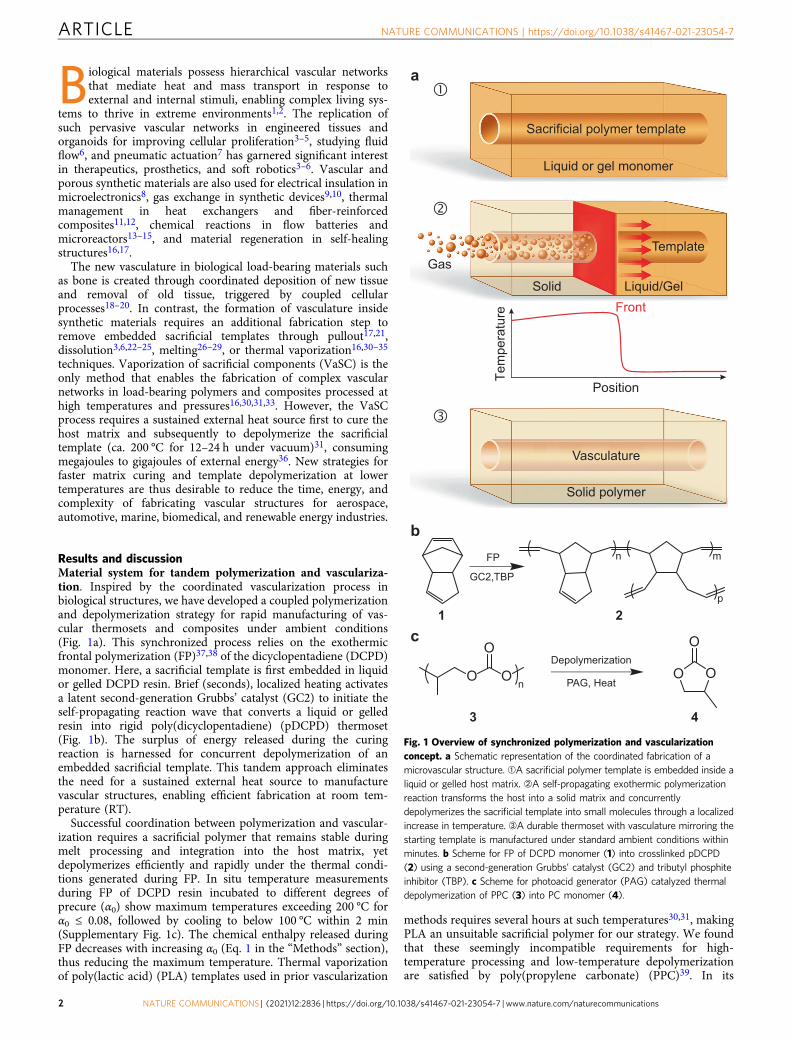
Successful vascularization window in neat thermosets. Initially,we investigated the depolymerization of a single UV-irradiatedPPC (1% PAG) fiber in tandem with FP of a DCPD gel (α0 =0.25) (Fig. 2a). The sacrificial fiber is embedded in liquid resin-which cures slowly at RT into a gel with the desired
α0 (Supplementary Table 1). FP is triggered by briefly poweringa resistive wire oriented perpendicular to the fiber. Thepolymerization front propagates through the specimen at ca.0.6 mm s−1 and vascularization trails by ca. 1.5 mm (Fig. 2a,Supplementary Video 1). A slight distortion in the shape of thepolymerization front also occurs near the sacrificial fiber. Tem-poral delays associated with heat conduction from the matrix tothe template and its subsequent endothermic depolymerizationinto liquid and gaseous molecules are responsible for theseobservations. Optical microscopy of the microchannel cross sec-tion and X-ray computed microtomography (μCT) reconstruc-tion of the microchannel volume reveal that the dimensions andcircularity of the channel replicate the sacrificial fiber (Supple-mentary Fig. 4 and Supplementary Table 5). As expected, as-spunfibers without UV irradiation do not depolymerize in similarexperiments (Supplementary Fig. 5). Vascularization of pDCPDspecimens with UV-irradiated sacrificial fibers occurs in less than2 min under ambient conditions after triggering FP. Activation ofthe PAG and FP initiation require minimal energy input, ca.108 J, reducing the thermal energy consumption by six orders ofmagnitude compared to ca. 120 MJ estimated for conventionalcuring and VaSC steps for samples of similar size (SupplementaryTable 2).
The depolymerization kinetics of PPC is highly temperature-sensitive (Supplementary Fig. 6a, b) and successful vasculariza-tion depends on the surplus heat released by the host matrixduring FP. Using the single sacrificial fiber geometry inside a glass
front
front
0.0 0.1 0.2 0.3 0.4 0.50.0
0.2
0.4
0.6
0.8
1.0
1.2
Degree of precure, � 0
Fron
t vel
o city
, Vfr o
nt (m
m s
-1)
0
50
100
150
200
250 Front tempe ra tur e, T
f ront (°C)
a
c
b
d
FPNo VaSC
No FPNo VaSC
FPVaSC
Template
500 μm
Front
y
x
pDCPD Gel
0.00.20.40.60.81.0
VasculatureVT
Template
500 μm
FrontpDCPD Gel
� �,0 5 10 15 20
0.0
0.2
0.4
0.6
0.8
1.0
� �
Position, x (mm)
Deg
ree
of c
ure,
�0.0
0.2
0.4
0.6
0.8
1.0
Degree of d epoly m
eriz ati on, �
� ������
������
Fig. 2 Experimental characterization and thermochemical modeling of the coordinated vascularization process. a Optical image of propagating FPreaction in a DCPD gel (α0 = 0.25) in tandem with depolymerization of an embedded PPC (1% PAG) template to create vascular pDCPD (t= 31 s afterinitiation). b Front velocity (black triangles) and maximum front temperature (red squares) during FP as a function of α0 of the DCPD gel. Successful VaSCthrough complete depolymerization of PPC depends on the amount of heat released during FP, which decreases with increasing α0. Sacrificial templatesundergo complete depolymerization for α0 ≤ 0.25. Partial depolymerization results in clogged microchannels for 0.30≤ α0 ≤ 0.35 and FP is no longerpossible for α0 ≥ 0.40. Error bars represent one standard deviation from the mean (n= 3). c Simulation of a DCPD gel (α0 = 0.25) showing the spatialdistribution of the degree of cure (α) of DCPD and the degree of depolymerization (β) of the sacrificial template during FP (t= 31 s after initiation). dPredicted spatial variation of α and β in the direction of the propagating front (t= 31 s after initiation). Successful polymerization and vascularization aredefined by α and β reaching 0.90 or higher, as shown by the α0 = 0.25 case (orange lines). The α0 = 0.35 case (blue lines) shows successfulpolymerization but unsuccessful vascularization, corroborating experimental observations.
NATURE COMMUNICATIONS | https://doi.org/10.1038/s41467-021-23054-7 ARTICLE
NATURE COMMUNICATIONS | (2021) 12:2836 | https://doi.org/10.1038/s41467-021-23054-7 | www.nature.com/naturecommunications 3
mold, we explore the potential range of α0 for vascularization ofthe host matrix. As α0 increases, both the front velocity (Vfront)and maximum front temperature (Tfront) decrease (Fig. 2b) due toa reduction in the fraction of chemical bonds capable of ring-opening during FP38. Concurrent FP and vascularization occurfor α0 ≤ 0.25, yielding fully evacuated channels. While thepolymerization front still propagates in gels with 0.30 ≤ α0 ≤ 0.35,the released heat is insufficient for complete depolymerization ofthe sacrificial fiber, leaving partially to fully obstructed micro-channels (Supplementary Fig. 8). The polymerization front doesnot propagate in gels with α0 ≥ 0.40 due to the reduced heatreleased during FP and heat loss to the glass mold.
Numerical modeling of coupled polymerization and depoly-merization. To gain insight into the tandem vascularizationprocess, we developed a coupled thermochemical model for thethermal field (T), the degree of cure (α) of DCPD, and the degreeof depolymerization (β) of PPC. The reaction-diffusion model38
was implemented in a transient, nonlinear finite-element solver(see “Methods” section). Successful curing and depolymerizationare numerically defined by α ≥ 0.90 and β ≥ 0.90, respectively.The simulation shown in Fig. 2c predicts localized deceleration ofthe polymerization front near the sacrificial template and a spatialdelay in vascularization with respect to the location of the front,which are observed experimentally in Fig. 2a. The computationalresults reveal that these observations are the consequence of thetime required for heat to transfer from the cured pDCPD into thePPC template for endothermic depolymerization. The Vfront andTfront predictions for different α0 also match closely withexperiments in the presence of the glass molds (SupplementaryFig. 9). The model predicts successful curing and vascularizationfor α0 = 0.25, while also predicting unsuccessful vascularizationdue to incomplete depolymerization of PPC for α0 = 0.35(Fig. 2d), as observed experimentally.
We further exploited this coupled thermochemical model toinvestigate the effect of a more insulating boundary condition(i.e., air) on the window for successful vascularization. Slightlyhigher Vfront and Tfront are predicted for an air boundarycompared to a glass mold boundary (Supplementary Fig. 10). Thelower convective heat loss to air compared to the conduction-driven heat loss to the glass mold allows longer heat retention inthe matrix after FP, thereby extending the window forvascularization to α0 ≤ 0.35 and the window for front propagationto α0 ≤ 0.50. To compare these predictions with experiments,elastomeric DCPD gels with α0 > 0.20 containing sacrificial fibersare removed from the molds and subjected to FP. The Vfront andTfront measurements along with the successful vascularizationregime agree with the calculations from the model and thecooling profile of the matrix after FP is substantially slower(Supplementary Fig. 1c). The model successfully captures thethermochemical competition between the heat generated by thehost matrix, the heat consumed by the depolymerizing fiber, andthe heat lost to the surroundings, which determine the successfulfabrication of vascular structures.
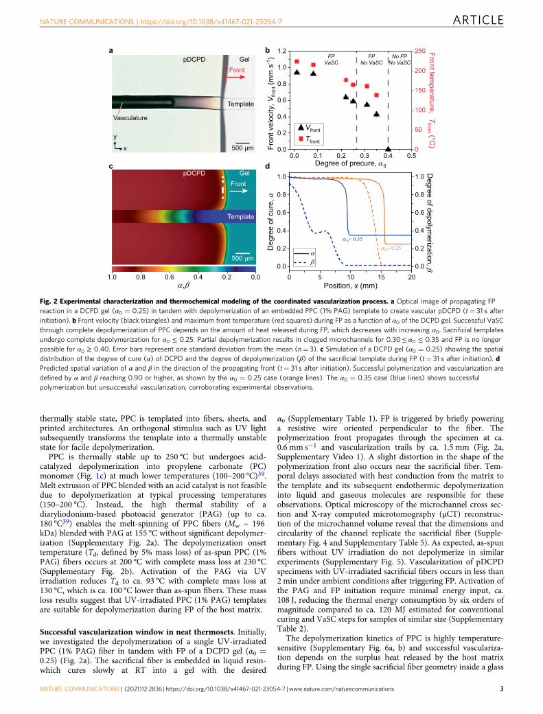
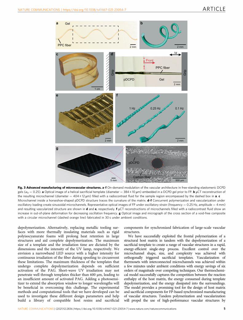
Advanced manufacturing of microvascular structures. Ourconcurrent vascularization strategy offers excellent control overthe matrix and microchannel architecture. Incubating the resin atRT to obtain viscoelastic gels proves advantageous for passive anddynamic modulation of the microchannel architecture. A range ofcomplex vascular structures (Fig. 3a–f) is easily fabricated fromelastomeric DCPD gels containing sacrificial PPC (1% PAG)templates. A 3D helical microchannel is created in pDCPD froma heat-set PPC template (Fig. 3a, b). μCT reconstruction of themicrochannel reveals excellent dimensional and morphological
fidelity. A flat gel with a straight fiber is bent into a horseshoeshape prior to FP without fracturing the template and this shapeis preserved in the resulting microchannel (Fig. 3c). Further, thisvascularization process also enables in situ modulation of thevascular geometry by applying oscillatory strain to a gel with asacrificial template during FP (Fig. 3d and SupplementaryVideo 2). The polymerization front permanently sets theinstantaneous out-of-plane deformation experienced by the geland the fiber during each loading cycle (Fig. 3e). The pitch andamplitude of the channel are tuned by controlling the oscillationfrequency (Fig. 3f). Such control over vascular features may finduse in particle/cell separation40 or mixing of multiple fluids vianon-laminar flow26.
Vascularized carbon-fiber-reinforced composites with circularmicrochannels are also rapidly manufactured with the FP-basedmethod (Fig. 3g and Supplementary Table 5). The presence of thefiber reinforcement exacerbates the thermochemical competitionbetween FP and VaSC processes due to the decreased resinvolume, resulting in lower front temperatures38. Additional PAGis added to the PPC fibers to accelerate the depolymerizationkinetics and achieve complete mass loss at lower temperatures(Supplementary Fig. 2c). PPC (3% PAG) fibers are sandwichedbetween layers of carbon-fiber fabric, then the fabric layup isinfused with a liquid DCPD monomer. Briefly powering aresistive heating mat underneath the impregnated fabric stacktriggers FP through the thickness of the laminate and facilitateslonger heat retention in the cured composite, which ensurescomplete depolymerization of the sacrificial fiber. The fabricationtime and energy are reduced by three and four orders ofmagnitude, respectively, compared to conventional curing andvascularization of similar size samples in an oven (SupplementaryTable 2). We anticipate even more significant energy savings forlarger components. For traditional autoclave cure and vaporiza-tion of templates at high temperature, energy consumption scalesdirectly with part size36,38. In great contrast, the required energyinput per unit volume for FP-mediated processing actuallydecreases with increasing component size38.
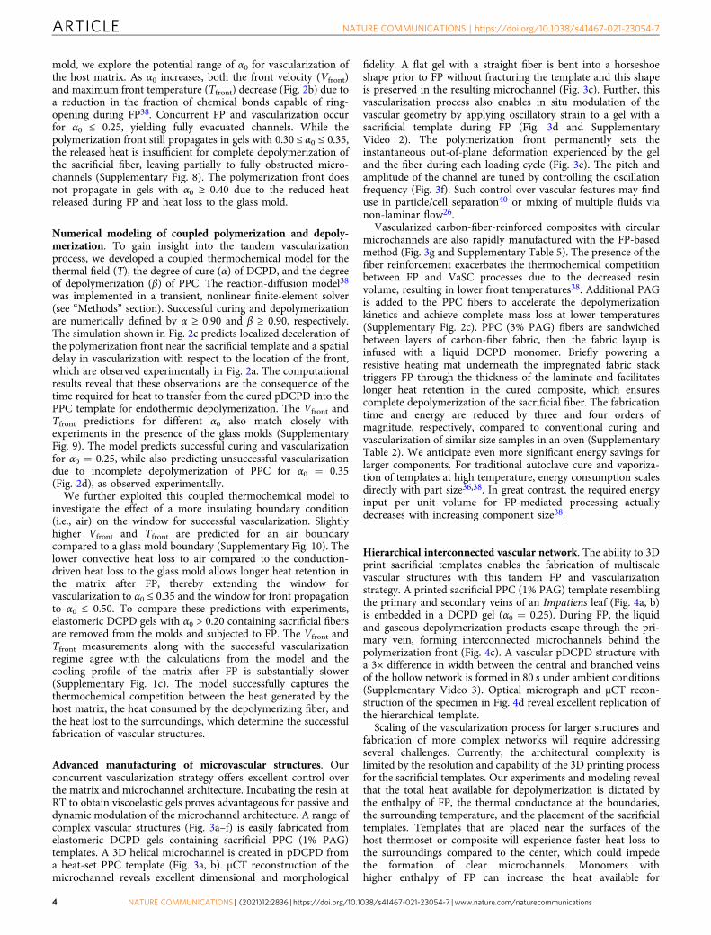
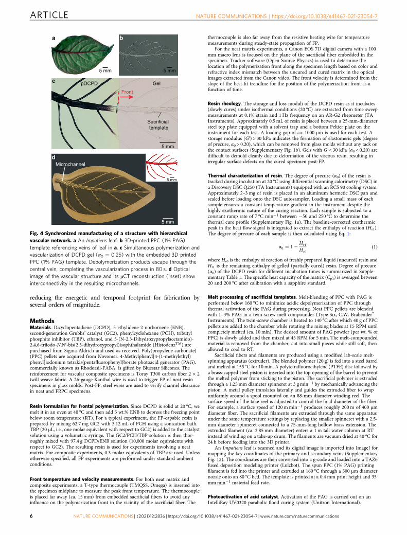
Hierarchical interconnected vascular network. The ability to 3Dprint sacrificial templates enables the fabrication of multiscalevascular structures with this tandem FP and vascularizationstrategy. A printed sacrificial PPC (1% PAG) template resemblingthe primary and secondary veins of an Impatiens leaf (Fig. 4a, b)is embedded in a DCPD gel (α0 = 0.25). During FP, the liquidand gaseous depolymerization products escape through the pri-mary vein, forming interconnected microchannels behind thepolymerization front (Fig. 4c). A vascular pDCPD structure witha 3× difference in width between the central and branched veinsof the hollow network is formed in 80 s under ambient conditions(Supplementary Video 3). Optical micrograph and μCT recon-struction of the specimen in Fig. 4d reveal excellent replication ofthe hierarchical template.
Scaling of the vascularization process for larger structures andfabrication of more complex networks will require addressingseveral challenges. Currently, the architectural complexity islimited by the resolution and capability of the 3D printing processfor the sacrificial templates. Our experiments and modeling revealthat the total heat available for depolymerization is dictated bythe enthalpy of FP, the thermal conductance at the boundaries,the surrounding temperature, and the placement of the sacrificialtemplates. Templates that are placed near the surfaces of thehost thermoset or composite will experience faster heat loss tothe surroundings compared to the center, which could impedethe formation of clear microchannels. Monomers withhigher enthalpy of FP can increase the heat available for
ARTICLE NATURE COMMUNICATIONS | https://doi.org/10.1038/s41467-021-23054-7
4 NATURE COMMUNICATIONS | (2021) 12:2836 | https://doi.org/10.1038/s41467-021-23054-7 | www.nature.com/naturecommunications
depolymerization. Alternatively, replacing metallic tooling sur-faces with more thermally insulating materials such as rigidpolyisocyanurate foams will prolong heat retention in largestructures and aid complete depolymerization. The maximumsize of a template and the irradiation time are dictated by thedimensions and the intensity of the UV lamp, respectively. Weenvision a narrowband LED source with a higher intensity forcontinuous irradiation of the fiber during spooling to circumventthese limitations. The maximum thickness of the templates thatundergo complete depolymerization depends on sufficientactivation of the PAG. Short-wave UV irradiation may notpenetrate well through templates thicker than 600 μm, leading toan insufficient amount of activated PAG. Adding a photosensi-tizer to extend the absorption window to longer wavelengths willbe beneficial in overcoming this challenge. The experimentalmethods and computational tools that we have developed can beused to investigate these different design parameters and helpbuild a library of compatible host resins and sacrificial
components for synchronized fabrication of large-scale vascularstructures.
We have successfully exploited the frontal polymerization of astructural host matrix in tandem with the depolymerization of asacrificial template to create a range of vascular structures in a rapid,energy-efficient single-step process. Excellent control over themicrochannel shape, size, and complexity was achieved withorthogonally triggered sacrificial templates. Vascularization ofthermosets with interconnected microchannels was achieved withina few minutes under ambient conditions with energy savings of sixorders of magnitude over competing techniques. Our thermochemi-cal model successfully captures the competition between the reactionenthalpy of the host matrix, the energy consumed during templatedepolymerization, and the energy dissipated into the surroundings.The model provides a promising tool for the design of host matrixand sacrificial components for FP-based synchronized manufacturingof vascular structures. Tandem polymerization and vascularizationwill propel the use of high-performance vascular structures by
Grip
Grip
c
1 cm
f
0.25 Hz1 Hz 0.1 Hz
2 mm 2 mmPPC fiber
Gela b
PPC fiber
Gel
Front
∆ε
e
pDCPD 2 mm
2 mm2 mm
d
Carbon fiber
pDCPD
g
500 μm5 mm
Fig. 3 Advanced manufacturing of microvascular structures. a–f On-demand modulation of the vascular architecture in free-standing elastomeric DCPDgels (α0 = 0.25). a Optical image of a helical sacrificial template (diameter = 384 ± 10 μm) embedded in a DCPD gel prior to FP. b μCT reconstruction ofthe resulting microchannel (diameter = 404 ± 12 μm) filled with a radiocontrast fluid for the sample region encompassed by the dashed box in a. cMicrochannel inside a horseshoe-shaped pDCPD structure traces the curvature of the matrix. d–f Concurrent polymerization and vascularization underoscillatory loading create sinusoidal microchannels. Representative optical images of FP under oscillatory strain (frequency = 0.25 Hz, amplitude = 4mm)and resulting vascularized structure are shown in d and e, respectively. f µCT reconstructions of microchannels filled with a radiocontrast fluid show anincrease in out-of-plane deformation for decreasing oscillation frequency. g Optical image and micrograph of the cross section of a void-free compositewith a circular microchannel (dashed orange line) fabricated in 30 s under ambient conditions.
NATURE COMMUNICATIONS | https://doi.org/10.1038/s41467-021-23054-7 ARTICLE
NATURE COMMUNICATIONS | (2021) 12:2836 | https://doi.org/10.1038/s41467-021-23054-7 | www.nature.com/naturecommunications 5
reducing the energetic and temporal footprint for fabrication byseveral orders of magnitude.
MethodsMaterials. Dicyclopentadiene (DCPD), 5-ethylidene-2-norbornene (ENB),second-generation Grubbs’ catalyst (GC2), phenylcyclohexane (PCH), tributylphosphite inhibitor (TBP), ethanol, and 5-(N-2,3-Dihydroxypropylacetamido)-2,4,6-triiodo-N,N′-bis(2,3-dihydroxypropyl)isophthalamide (HistodenzTM) arepurchased from Sigma-Aldrich and used as received. Poly(propylene carbonate)(PPC) pellets are acquired from Novomer. 4-Methylphenyl[4-(1-methylethyl)phenyl]iodonium tetrakis(pentafluorophenyl)borate photoacid generator (PAG),commercially known as Rhodorsil-FABA, is gifted by Bluestar Silicones. Thereinforcement for vascular composite specimens is Toray T300 carbon fiber 2 × 2twill weave fabric. A 26-gauge Kanthal wire is used to trigger FP of neat resinspecimens in glass molds. Post-FP, steel wires are used to verify channel clearancein neat and FRPC specimens.
Resin formulation for frontal polymerization. Since DCPD is solid at 20 °C, wemelt it in an oven at 40 °C and then add 5 wt.% ENB to depress the freezing pointbelow room temperature (RT). For a typical experiment, the FP-capable resin isprepared by mixing 62.7 mg GC2 with 3.12 mL of PCH using a sonication bath.TBP (20 μL, i.e., one molar equivalent with respect to GC2) is added to the catalystsolution using a volumetric syringe. The GC2/PCH/TBP solution is then thor-oughly mixed with 97.4 g DCPD/ENB solution (10,000 molar equivalents withrespect to GC2). The resulting resin is used for experiments involving a neatmatrix. For composite experiments, 0.3 molar equivalents of TBP are used. Unlessotherwise specified, all FP experiments are performed under standard ambientconditions.
Front temperature and velocity measurements. For both neat matrix andcomposite experiments, a T-type thermocouple (TMQSS, Omega) is inserted intothe specimen midplane to measure the peak front temperature. The thermocoupleis placed far away (ca. 15 mm) from embedded sacrificial fibers to avoid anyinfluence on the polymerization front in the vicinity of the sacrificial fiber. The
thermocouple is also far away from the resistive heating wire for temperaturemeasurements during steady-state propagation of FP.
For the neat matrix experiments, a Canon EOS 7D digital camera with a 100mm macro lens is focused on the plane of the sacrificial fiber embedded in thespecimen. Tracker software (Open Source Physics) is used to determine thelocation of the polymerization front along the specimen length based on color andrefractive index mismatch between the uncured and cured matrix in the opticalimages extracted from the Canon video. The front velocity is determined from theslope of the best-fit trendline for the position of the polymerization front as afunction of time.
Resin rheology. The storage and loss moduli of the DCPD resin as it incubates(slowly cures) under isothermal conditions (20 °C) are extracted from time sweepmeasurements at 0.1% strain and 1 Hz frequency on an AR-G2 rheometer (TAInstruments). Approximately 0.5 mL of resin is placed between a 25-mm-diametersteel top plate equipped with a solvent trap and a bottom Peltier plate on theinstrument for each test. A loading gap of ca. 1000 μm is used for each test. Astorage modulus (G′) > 30 kPa indicates the formation of elastomeric gels (degreeof precure, α0 > 0.20), which can be removed from glass molds without any tack onthe contact surfaces (Supplementary Fig. 1b). Gels with G' < 30 kPa (α0 < 0.20) aredifficult to demold cleanly due to deformation of the viscous resin, resulting inirregular surface defects on the cured specimen post-FP.
Thermal characterization of resin. The degree of precure (α0) of the resin istracked during incubation at 20 °C using differential scanning calorimetry (DSC) ina Discovery DSC Q250 (TA Instruments) equipped with an RCS 90 cooling system.Approximately 2–3 mg of resin is placed in an aluminum hermetic DSC pan andsealed before loading onto the DSC autosampler. Loading a small mass of eachsample ensures a constant temperature gradient in the instrument despite thehighly exothermic nature of the curing reaction. Each sample is subjected to aconstant ramp rate of 7 °C min−1 between −50 and 250 °C to determine thethermal cure profile (Supplementary Fig. 1a). The baseline-corrected exothermicpeak in the heat flow signal is integrated to extract the enthalpy of reaction (Hr1).The degree of precure of each sample is then calculated using Eq. 1:
α0 ¼ 1�Hr1
Hr0ð1Þ
where Hr0 is the enthalpy of reaction of freshly prepared liquid (uncured) resin andHr1 is the remaining enthalpy of gelled (partially cured) resin. Degree of precure(α0) of the DCPD resin for different incubation times is summarized in Supple-mentary Table 1. The specific heat capacity of the matrix (Cp1) is averaged between20 and 200 °C after calibration with a sapphire standard.
Melt processing of sacrificial templates. Melt-blending of PPC with PAG isperformed below 160 °C to minimize acidic depolymerization of PPC throughthermal activation of the PAG during processing. Neat PPC pellets are blendedwith 1–3% PAG in a twin-screw melt compounder (Type Six, C.W. Brabender®
Instruments). The twin-screw chamber is heated to 140 °C after which 40 g of PPCpellets are added to the chamber while rotating the mixing blades at 15 RPM untilcompletely melted (ca. 10 min). The desired amount of PAG powder (per wt. % ofPPC) is slowly added and then mixed at 45 RPM for 5 min. The melt-compoundedmaterial is removed from the chamber, cut into small pieces while still soft, thenallowed to cool to RT.
Sacrificial fibers and filaments are produced using a modified lab-scale melt-spinning apparatus (extruder). The blended polymer (20 g) is fed into a steel barreland melted at 155 °C for 10 min. A polytetrafluoroethylene (PTFE) disc followed bya brass-capped steel piston is inserted into the top opening of the barrel to preventthe melted polymer from sticking to the piston. The sacrificial polymer is extrudedthrough a 1.25 mm diameter spinneret at 3 g min−1 by mechanically advancing thepiston. A metal pulley translates laterally and guides the extruded fiber to wrapuniformly around a spool mounted on an 88-mm diameter winding reel. Thesurface speed of the take reel is adjusted to control the final diameter of the fiber.For example, a surface speed of 120 mmin−1 produces roughly 200 m of 400 μmdiameter fiber. The sacrificial filaments are extruded through the same apparatusunder the same temperature settings by replacing the smaller spinneret with a 2.5-mm diameter spinneret connected to a 75-mm-long hollow brass extension. Theextruded filament (ca. 2.85 mm diameter) enters a 1 m tall water column at RTinstead of winding on a take-up drum. The filaments are vacuum dried at 40 °C for24 h before feeding into the 3D printer.
An Impatiens leaf is scanned and its digital image is imported into ImageJ formapping the key coordinates of the primary and secondary veins (SupplementaryFig. 12). The coordinates are then converted into a g-code and loaded into a TAZ6fused deposition modeling printer (Lulzbot). The spun PPC (1% PAG) printingfilament is fed into the printer and extruded at 160 °C through a 500 μm diameternozzle onto an 80 °C bed. The template is printed at a 0.4 mm print height and 35mmmin−1 material feed rate.
Photoactivation of acid catalyst. Activation of the PAG is carried out on anIntelliRay UV0320 parabolic flood curing system (Unitron International).
c
5 mm
5 mm
5 mm
FrontGelpDCPD
Microchannel
Sacrificial template
d
a
5 mm 5 mm
b
Fig. 4 Synchronized manufacturing of a structure with hierarchicalvascular network. a An Impatiens leaf. b 3D-printed PPC (1% PAG)template referencing veins of leaf in a. c Simultaneous polymerization andvascularization of DCPD gel (α0 = 0.25) with the embedded 3D-printedPPC (1% PAG) template. Depolymerization products escape through thecentral vein, completing the vascularization process in 80 s. d Opticalimage of the vascular structure and its µCT reconstruction (inset) showinterconnectivity in the resulting microchannels.
ARTICLE NATURE COMMUNICATIONS | https://doi.org/10.1038/s41467-021-23054-7
6 NATURE COMMUNICATIONS | (2021) 12:2836 | https://doi.org/10.1038/s41467-021-23054-7 | www.nature.com/naturecommunications
Sacrificial fibers (15 cm long and 400–600 µm diameter) or printed templates areplaced on an aluminum foil and taped at the ends to prevent shrinking duringirradiation. The foil is secured on an adjustable metal shelf 75 mm below the lampsuch that all the fibers are within the area projected by the lamp. The fibers areirradiated for a total of 10 min at 100% power (6–8 J cm−2 at 280 nm). The tem-plates are flipped after 5 min to promote activation of the PAG through thethickness of the sacrificial polymer. The templates are either used immediately afterirradiation or stored at −20 °C in a lightproof box until use. The UV irradiationtime for the templates is not optimized and a more powerful UV source would beideal for activating the PAG rapidly within seconds. Unless otherwise specified, allreferences to the sacrificial fibers or templates refer to UV-irradiated material.
Characterization of sacrificial templates. Scanning electron micrographs (SEM)of the fibers are acquired on a FEI Quanta FEG 450 Environmental SEM. Samplesare imaged at 5 kV after sputter coating with gold/palladium for 70 s (ca. 7 nm)using a Denton Desk II TSC-turbo-pumped sputter coater.
Molecular weights of pellets and fibers are obtained via analytical gelpermeation chromatography (GPC) on a system composed of a Waters (1515)Isocratic high-pressure liquid chromatography pump, a Waters (2414) RefractiveIndex Detector, a Waters (2707) 96-well autosampler, and a series of 4 Waters HRStyragel columns (7.8 × 300 mm, HR1, HR3, HR4, and HR5) in tetrahydrofuran(THF) at 30 °C. The GPC is calibrated using monodisperse polystyrene standards.Each sample (10 mg) is weighed on an analytical balance (XPE205, Mettler-Toledo)and dissolved in 1 mL THF. The polymer solution is injected into a 300 μL GPCvial through a 0.45 μm polytetrafluoroethylene (PTFE) filter to remove anyundissolved particulates before loading it into the GPC autosampler. Number- andweight-averaged molecular weights (Mn and Mw) are calculated using Wyatt’sAstra 6 software through the integration of the signal peaks obtained from the RIdetector (Supplementary Fig. 2a).
Thermal depolymerization via mass loss of sacrificial templates (3 mg samples)in a nitrogen environment was measured on a TGA (Q500, TA Instruments)equipped with an evolved gas analysis furnace and calibrated with nickel standards(Supplementary Fig. 2b, c). For dynamic tests, the mass loss is recorded during aheating cycle over the temperature range from 40–250 °C at a linear ramp rate of1–100 °C min−1. Instrument limitations caused a nonlinear increase in initialtemperature from 40 to 100 °C for high ramp rates (>40 °C min−1). For isothermaltests, the temperature is ramped from 40 to 10 °C below the desired temperature ata linear ramp rate of 10 °C min−1, then subsequently ramped to the desiredtemperature at a slower linear rate of 5 °C min−1 to minimize temperatureovershoot. The isothermal temperature is maintained for 3–6 h for each test.
The glass transition temperature (Tg), heat capacity (Cp2), and enthalpy ofdepolymerization (Hr2) of PPC fibers are measured on the DSC Q250(Supplementary Fig. 6c, d). Approximately 2–3 mg of the sacrificial polymer issealed in an aluminum hermetic DSC pan and exposed to a constant ramp rate of5 °C min−1 between −50 and 180 °C. The specific heat capacity of the fibers isaveraged between 20 and 140 °C after calibration with a sapphire standard. The Hr2
of the sacrificial polymer is extracted by integrating the baseline-correctedendothermic peak in the heat flow signal between 50 and 180 °C. For open-panDSC experiments, a TA instrument Q20 DSC connected to a CFL-50 coolingsystem is used. The enthalpy of vaporization of PC monomer (integrated between60 and 150 °C) is subtracted from the enthalpy of vaporization of PPC (1% PAG)fiber to estimate the enthalpy of depolymerization of the fiber.
Specimen fabrication for vascularized neat polymer. For FP of specimens inglass molds, a single PPC (1% PAG) fiber is clamped between two polyurethanespacers (inner dimensions: 60.0 mm × 34.0 mm × 6.0 mm) and sandwichedbetween two 76.2 mm × 50.8 mm × 6.4 mm glass plates in a cell casting mold(Supplementary Fig. 3). Liquid resin is poured into each mold to completelysubmerge the fiber. A resistive wire perpendicular to the fiber orientation is thenplaced in the resin. Resin-filled molds are incubated in an environmental testchamber (MicroClimate, Cincinnati Sub-Zero Products) at 20 °C to achieve thedesired degree of precure (α0) (Supplementary Table 1). Once the desired α0 isreached, FP of the gelled sample is initiated by briefly powering (6W for ca. 3 s) theresistive wire.
For FP of specimens without the glass mold, the precured elastomeric gelspecimens are removed from the cell casting mold once α0 > 0.20. The edges of thespecimens are trimmed with a razor blade to expose the transverse ends of thesacrificial fiber. FP is then initiated by applying a soldering iron to one end of thespecimen.
For the helical microchannel in Fig. 3a, b, a PPC fiber (1% PAG) is heat-set at40 °C into the desired shape before embedding in the glass mold and fillingwith resin.
For dynamic modulation experiments in Fig. 3d–f, DCPD gels containing asingle sacrificial fiber (located at 1 mm from the surface of a 4-mm-thick sample)are fixed between tensile grips on an Instron 8841 fatigue frame with a gauge lengthof 50 mm. FP is thermally initiated using a soldering iron at one end of the sample,and dynamic (sinusoidal) loading is applied as the front propagates. Frontpropagation, applied tension, and fiber orientation are all in the same direction.The displacement amplitude is maintained at 4 mm for all samples and thefrequency is varied from 0.1 to 1 Hz.
For the leaf specimen in Fig. 4, the PPC (1% PAG) template was submerged inliquid DCPD resin inside a glass mold that was subsequently incubated at RT for~12 h prior to initiating FP. The gelled specimen (α0 ~ 0.25) was removed from themold and a soldering iron was used to trigger the FP on one side perpendicular tothe primary vein of the template.
Microchannel characterization and reconstruction. The vasculature is rinsedwith ethanol after FP and optical images of polished cross sections are captured ona Keyence VHX-5000 digital microscope at 100×-200× magnification. Micro-channels within the host matrices are also visualized with X-ray computedmicrotomographic (μCT) imaging (Xradia MicroXCT-400 using TXM Controllersoftware). The μCT scans are conducted after infiltrating the empty microchannelswith a contrast solution (350 mg HistodenzTM in 1 g DI water). For 5-mm longchannels, 360° scans are obtained in rotation intervals of 0.4° with a ×4 objective (5μm per pixel) at 5 s exposure times with 40 kV (200 μA, 8W) source. For 20-mmlong microchannels, imaging settings are changed to rotation intervals of 0.5° witha ×1 objective (20 μm per pixel) at 3 s exposure times with 60 kV (133 μA, 8W)source. Scan reconstructions are completed in a proprietary software and imagesare produced via AmiraTM (v. 6.4.0). ImageJ software is used to measure thedimensions and circularity of the channels from optical images and μCT recon-structions (Supplementary Table 5).
Computational modeling of coupled polymerization and vascularization. Thefrontal polymerization of DCPD and the depolymerization of PPC are coupledthermochemical processes described by their own reaction-diffusion model. Forcomputational efficiency, we simulate the PPC fiber embedded in a cylindricalDCPD domain (Supplementary Fig. 7a) in an axisymmetric setting. In the DCPDdomain, the thermochemical model expressed in terms of the temperature, T (inK), and degree-of-cure, α, takes the form
κ1∂2T∂r2 þ κ1
1r∂T∂r þ κ1
∂2T∂z2 þ ρ1Hr1
∂α∂t ¼ ρ1Cp1
∂T∂t
∂α∂t ¼ A1 exp
�� Ea1RT
�ð1� αÞn1αm1 11þexp½Cðα�αc�α0Þ�
(
ð2Þ
where the subscript “1” denotes quantities associated with DCPD, α = 0 denotes theuncured resin, and α = 1 denotes the fully cured polymer. In (2), κ (in W m−2 K−1)denotes the thermal conductivity, ρ (in kg m−3) the density, Cp (in J g−1 K−1) thespecific heat, and Hr (in J g−1) the total enthalpy of reaction. The second equation in(2) captures the cure kinetics, with A (in s−1) denoting the pre-exponential con-stant, Ea (in kJ mol−1) the activation energy, and R (= 8.314 J mol−1 K−1) theuniversal gas constant. The additional terms appearing in the cure kinetic model arebased on the Prout–Tompkins auto-catalytic model41 ð1þ exp½Cðα� αc � α0Þ�Þ�1,which also accounts for α0. This model has been successfully used to simulate FP inDCPD monomer42 and DCPD-based composites43–45. Supplementary Table 3provides the material properties and Supplementary Table 4 provides the curekinetic parameters for DCPD.
The depolymerization process of the PPC fiber is described similarly in terms ofthe thermal field and the degree of depolymerization β, with β ¼ 0 correspondingto the intact PPC and β ¼ 1 the fully depolymerized state:
κ2∂2T∂r2 þ κ2
1r∂T∂r þ κ2
∂2T∂z2 � ρ2Hr2
∂β∂t ¼ ρ2Cp2
∂T∂t
∂β∂t ¼ A2 exp
�� Ea2RT
�ð1� βÞn2βm2
(
ð3Þ
where the subscript “2” denotes quantities associated with PPC, and Hr2 the totalheat absorbed per unit mass by the depolymerization of the sacrificial material. Toextract the parameters defining the depolymerization kinetics of PPC, aconstrained nonlinear multi-variable optimization algorithm46 is adopted to matchdynamic TGA data obtained at different ramping rates (Supplementary Fig. 6a, b).The material properties and depolymerization kinetics parameters used in thisstudy for PPC are listed in Supplementary Tables 3 and 4, respectively.
As shown in Supplementary Fig. 7b, convective boundary conditions (with afilm coefficient h and an ambient temperature of 20 °C) are applied along the outersurfaces of the cylindrical domain. In the simulation, the DCPD radius (r1) is 3mm, the fiber radius (r2) is 200 μm, and the length of the domain (l) is 20 mm.Initiation of the FP process is achieved by prescribing a temperature (200 °C) forone second along the edge at x = 0. The film coefficient is chosen (h = 25Wm−2
K−1) such that the temperature profile in the DCPD is similar to that measured inthe experiments. For the simulations involving a glass mold, a glass layer is addedalong the top of the simulation domain with a glass thickness of 0.7 mm to capturethe temperature history (Supplementary Fig. 7c). In that glass layer, the transientheat conduction equation (in the absence of the reaction term) is solved, with theconvective boundary condition applied to the surface of the glass layer exposedto air.
The analysis is performed with Multiphysics Object-Oriented SimulationEnvironment (MOOSE), an open-source C++ math library and nonlinear finite-element solver47 that provides the mesh adaptivity needed to capture accuratelyand efficiently the sharp gradients in temperature and degree of cure/depolymerization in the vicinity of the advancing front.
Specimen fabrication for vascularized fiber-reinforced composites. Compo-sites specimens are fabricated with 10 plies of 2 × 2 twill weave carbon-fiber fabric.
NATURE COMMUNICATIONS | https://doi.org/10.1038/s41467-021-23054-7 ARTICLE
NATURE COMMUNICATIONS | (2021) 12:2836 | https://doi.org/10.1038/s41467-021-23054-7 | www.nature.com/naturecommunications 7

The DCPD resin solution is prepared with 0.3 equivalents of TBP with respect toGC2. A wet layup technique is used to infuse the liquid DCPD resin into a 10 cmby 13 cm stack of dry carbon-fiber fabric with a PPC fiber (3% PAG, 400 μmdiameter) secured between the fifth and sixth layer (midplane of the fabric stack)(Supplementary Fig. 11). The layup is prepared on a resistive heater (OMEGA-LUX®), which is secured onto an insulator tool plate (448-D, Fibre Glast Devel-opments Corp.). Silicone spacers (4-mm thick) are placed adjacent to the layup todictate the cured composite thickness. An additional insulator tool plate is restedon top of the layup, then the entire setup is moved to a hydraulic press (MTP-13,Tetrahedron). A platen force of 2 kN is applied onto the setup and then FP isinitiated by powering the resistive heater. The heater was switched off as soon as aspike in the thermocouple temperature was observed (ca. 30 s) indicating that thefront has propagated through the composite thickness (Supplementary Fig. 1d).
Depolymerization of the sacrificial fiber post-FP is evaluated by passing a steelwire through the channel. The channel fidelity and void content in the curedcomposite are measured by polishing the cross sections of samples cut along thepanel, then imaging the polished surfaces via a digital optical microscope (VHX-5000, Keyence). ImageJ software is used to measure the circularity of the channeland to calculate the ratio of void to cross-sectional area for each polished sample.The composite fiber volume fraction, Vf, is calculated using Eq. 4:
V f ¼f Anρf z
ð4Þ
where fA is the areal weight of the fabric, ρf is the fiber density, n is the number ofplies, and z is the composite thickness.
Energy and time consumption calculations. The energy consumed during anyheating step is determined by multiplying the energy consumption rate by the steptime. The energy consumption rate during ramp and dwell steps for an oven with apower rating of 4.8 kW and an interior volume of 0.8 m3 were 0.046 and 0.024kWh min−1, respectively36. The following protocols were used for each process:
BPA-epoxy oven-cure cycle: ramp from 20 to 121 °C (50 min), dwell at 121 °C(2 h), ramp to 177 °C (25 min), and dwell at 177 °C (3 h).
DCPD oven-cure cycle: ramp from 20 to 70 °C (30 min), dwell at 70 °C (2 h),ramp to 170 °C (50 min), and dwell at 170 °C (1.5 h).
PLA VaSC cycle: ramp from 20 °C to 200 °C (2 h) and dwell at 200 °C (12 h).DCPD FP initiation with resistive wire: A DC source with 3 A at 2 V was
switched on for 3 s.FRPC FP initiation with heating mat: A 300W heater was powered on for 30 s.UV irradiation cycle for PPC: 10 min at 10 mW cm−2 for a 15 cm long fiber.
Data availabilitySource data are provided with this paper. Any supplementary data that support thefindings of this study are available from the corresponding author on reasonable request.
Code availabilityWe performed the simulations by developing an application based on MOOSE, an open-source C++ finite-element framework developed at Idaho National Laboratory. MOOSEis freely available at mooseframework.org. A compiled version of the code for simulatingthe synchronized manufacturing process, an example input file, and the instructions forrunning the simulations are provided and can be accessed under the MIT License athttps://gitlab.com/zhangx22/concurrentvascfp. These files could be used to reproduce thecomputational results reported in this manuscript or simulate the tandem polymerizationand depolymerization processes with a different geometrical settings, initial or boundaryconditions.
Received: 10 December 2020; Accepted: 7 April 2021;
References1. Campbell, N. A, Reece, J. B, Taylor, M. R, Simon, E. J & Dickey, J. L. Biology
(2010).2. Katifori, E., Szöllősi, G. J. & Magnasco, M. O. Damage and fluctuations induce
loops in optimal transport networks. Phys. Rev. Lett. 104, 048704 (2010).3. Miller, J. S. et al. Rapid casting of patterned vascular networks for perfusable
engineered three-dimensional tissues. Nat. Mater. 11, 768–774 (2012).4. Skylar-Scott, M. A. et al. Biomanufacturing of organ-specific tissues with high
cellular density and embedded vascular channels. Sci. Adv. 5, eaaw2459(2019).
5. Kinstlinger, I. S. et al. Generation of model tissues with dendritic vascularnetworks via sacrificial laser-sintered carbohydrate templates. Nat. Biomed.Eng. 4, 916–932 (2020).
6. Grigoryan, B. et al. Multivascular networks and functional intravasculartopologies within biocompatible hydrogels. Science 364, 458–464 (2019).
7. Mosadegh, B. et al. Pneumatic networks for soft robotics that actuate rapidly.Adv. Funct. Mater. 24, 2163–2170 (2014).
8. Spencer, T. J., Joseph, P. J., Kim, T. H., Swaminathan, M. & Kohl, P. A. Air-gap transmission lines on organic substrates for low-loss interconnects. IEEETrans. Microw. Theory Tech. 55, 1919–1925 (2007).
9. Potkay, J. A., Magnetta, M., Vinson, A. & Cmolik, B. Bio-inspired, efficient,artificial lung employing air as the ventilating gas. Lab Chip 11, 2901–2909 (2011).
10. Brubaker, K., Garewal, A., Steinhardt, R. C. & Esser-Kahn, A. P. Bio-inspiredcounter-current multiplier for enrichment of solutes. Nat. Commun. 9, 736 (2018).
11. Maloney, K. J. et al. Multifunctional heat exchangers derived from three-dimensional micro-lattice structures. Int. J. Heat. Mass Transf. 55, 2486–2493(2012).
12. Coppola, A. M., Griffin, A. S., Sottos, N. R. & White, S. R. Retention ofmechanical performance of polymer matrix composites above the glasstransition temperature by vascular cooling. Compos. Part A Appl. Sci. Manuf.78, 412–423 (2015).
13. Weber, A. Z. et al. Redox flow batteries: a review. J. Appl. Electrochem. 41,1137–1164 (2011).
14. Cambié, D., Zhao, F., Hessel, V., Debije, M. G. & Noël, T. A leaf-inspiredluminescent solar concentrator for energy-efficient continuous-flowphotochemistry. Angew. Chem. Int. Ed. 56, 1050–1054 (2016).
15. Trogadas, P. et al. A lung-inspired approach to scalable and robust fuel celldesign. Energ. Environ. Sci. 11, 136–143 (2017).
16. Patrick, J. F. et al. Continuous self-healing life cycle in vascularized structuralcomposites. Adv. Mater. 26, 4302–4308 (2014).
17. White, S. R. et al. Restoration of large damage volumes in polymers. Science344, 620–623 (2014).
18. Little, N., Rogers, B. & Flannery, M. Bone formation, remodelling and healing.Surgery 29, 141–145 (2011).
19. Härle, F & Boudrieau, R. J. Maxillofacial Bone Healing Oral and MaxillofacialSurgery in Dogs and Cats Ch. 2 (2012).
20. Sims, N. A. & Martin, T. J. Coupling the activities of bone formation andresorption: a multitude of signals within the basic multicellular unit. BoneKEyRep. 3, 481 (2014).
21. Norris, C. J., Bond, I. P. & Trask, R. S. Interactions between propagatingcracks and bioinspired self-healing vascules embedded in glass fibre reinforcedcomposites. Compos. Sci. Technol. 71, 847–853 (2011).
22. Beebe, D. J. et al. Functional hydrogel structures for autonomous flow controlinside microfluidic channels. Nature 404, 588–590 (2000).
23. Wu, H., Odom, T. W., Chiu, D. T. & Whitesides, G. M. Fabrication ofcomplex three-dimensional microchannel systems in PDMS. J. Am. Chem.Soc. 125, 554–559 (2003).
24. Skylar-Scott, M. A., Mueller, J., Visser, C. W. & Lewis, J. A. Voxelated softmatter via multimaterial multinozzle 3D printing. Nature 575, 330–335(2019).
25. Keene, S. T. et al. A biohybrid synapse with neurotransmitter-mediatedplasticity. Nat. Mater. 19, 969–973 (2020).
26. Therriault, D., White, S. R. & Lewis, J. A. Chaotic mixing in three-dimensionalmicrovascular networks fabricated by direct-write assembly. Nat. Mater. 2,265–271 (2003).
27. Toohey, K. S., Sottos, N. R., Lewis, J. A., Moore, J. S. & White, S. R. Self-healing materials with microvascular networks. Nat. Mater. 6, 581–585 (2007).
28. Trask, R. S. & Bond, I. P. Bioinspired engineering study of Plantae vascules forself-healing composite structures. J. R. Soc. Interface 7, 921–931 (2010).
29. Wu, W., DeConinck, A. & Lewis, J. A. Omnidirectional printing of 3Dmicrovascular networks. Adv. Mater. 23, H178–H183 (2011).
30. Esser-Kahn, A. P. et al. Three-dimensional microvascular fiber-reinforcedcomposites. Adv. Mater. 23, 3654–3658 (2011).
31. Gergely, R. C. R. et al. Multidimensional vascularized polymers usingdegradable sacrificial templates. Adv. Funct. Mater. 25, 1043–1052 (2014).
32. Patrick, J. F. et al. Robust sacrificial polymer templates for 3D interconnectedmicrovasculature in fiber-reinforced composites. Compos. Part A Appl. Sci.Manuf. 100, 361–370 (2017).
33. Pety, S. J. et al. Carbon fiber composites with 2D microvascular networks forbattery cooling. Int. J. Heat. Mass Transf. 115, 513–522 (2017).
34. Moore, D. G., Barbera, L., Masania, K. & Studart, A. R. Three-dimensionalprinting of multicomponent glasses using phase-separating resins. Nat. Mater.19, 212–217 (2019).
35. Qamar, I. P. S., Sottos, N. R. & Trask, R. S. Grand challenges in the designand manufacture of vascular self-healing. Multifunct. Mater. 3, 013001 (2020).
36. Witik, R. A. et al. Economic and environmental assessment of alternativeproduction methods for composite aircraft components. J. Clean. Prod. 29,91–102 (2012).
37. Pojman, J. A Polymer Science: A Comprehensive Reference Ch. 4 (2012).38. Robertson, I. D. et al. Rapid energy-efficient manufacturing of polymers and
composites via frontal polymerization. Nature 557, 223–227 (2018).39. Spencer, T. J. & Kohl, P. A. Decomposition of poly(propylene carbonate) with
UV sensitive iodonium salts. Polym. Degrad. Stab. 96, 686–702 (2011).
ARTICLE NATURE COMMUNICATIONS | https://doi.org/10.1038/s41467-021-23054-7
8 NATURE COMMUNICATIONS | (2021) 12:2836 | https://doi.org/10.1038/s41467-021-23054-7 | www.nature.com/naturecommunications
40. Lee, W. et al. 3D-Printed microfluidic device for the detection of pathogenicbacteria using size-based separation in helical channel with trapezoid cross-section. Sci. Rep. 5, 7717 (2015).
41. Yang, G. & Lee, J. K. Curing kinetics and mechanical properties of endo-dicyclopentadiene synthesized using different Grubbs’ catalysts. Ind. Eng.Chem. Res. 53, 3001–3011 (2014).
42. Goli, E., Robertson, I. D., Geubelle, P. H. & Moore, J. S. Frontalpolymerization of dicyclopentadiene: a numerical study. J. Phys. Chem. B. 122,4583–4591 (2018).
43. Vyas, S., Goli, E., Zhang, X. & Geubelle, P. H. Manufacturing of unidirectionalglass-fiber-reinforced composites via frontal polymerization: a numericalstudy. Compos. Sci. Technol. 184, 107832 (2019).
44. Vyas, S., Zhang, X., Goli, E. & Geubelle, P. H. Frontal vs. bulk polymerizationof fiber-reinforced polymer-matrix composites. Compos. Sci. Technol. 198,108303 (2020).
45. Goli, E. et al. Frontal polymerization of unidirectional carbon-fiber-reinforcedcomposites. Compos. Part. A Appl. Sci. Manuf. 130, 105689 (2020).
46. Powell, M. J. D. Numerical Analysis, Proceedings of the Biennial ConferenceHeld at Dundee 144–157 (1977).
47. Gaston, D., Newman, C., Hansen, G. & Lebrun-Grandié, D. MOOSE: aparallel computational framework for coupled systems of nonlinear equations.Nucl. Eng. Des. 239, 1768–1778 (2009).
AcknowledgementsWe acknowledge funding from the Air Force Office of Scientific Research (AFOSR#FA9550-20-1-0194, Center of Excellence in Self-healing and Morphogenic Manu-facturing). M.G. was supported by a PPG-MRL Graduate Fellowship, L.M.D. was sup-ported by an NSF Graduate Fellowship, E.M.L. was supported by a Beckman FoundationGraduate Fellowship. We thank J.L. Vazquez for their graphics assistance. We alsoacknowledge the late Prof. S. R. White who helped conceive this idea and contributed tothe research.
Author contributionsN.R.S., J.S.M., and P.H.G. directed the research. M.G. and I.D.R. conceived the idea. M.G., J.E.A., P.J.C., L.M.D., E.M.L., and M.Y designed the experiments and X.Z. conductedthe computational studies. For the experimental work, M.G. focused on sacrificial
polymer characterization and vascularization in neat thermosets, J.E.A. performed the 3Dprinting and rheological characterization, P.J.C. manufactured the vascular composites,L.M.D. helped with the oscillatory tests, and Y.L. performed the front velocity mea-surements. All authors participated in writing the manuscript.
Competing interestsThe authors have filed patent application US16809769 related to this work.
Additional informationSupplementary information The online version contains supplementary materialavailable at https://doi.org/10.1038/s41467-021-23054-7.
Correspondence and requests for materials should be addressed to N.R.S.
Peer review information Nature Communications thanks Edward Archer and the other,anonymous, reviewer(s) for their contribution to the peer review of this work.
Reprints and permission information is available at http://www.nature.com/reprints
Publisher’s note Springer Nature remains neutral with regard to jurisdictional claims inpublished maps and institutional affiliations.
Open Access This article is licensed under a Creative CommonsAttribution 4.0 International License, which permits use, sharing,
adaptation, distribution and reproduction in any medium or format, as long as you giveappropriate credit to the original author(s) and the source, provide a link to the CreativeCommons license, and indicate if changes were made. The images or other third partymaterial in this article are included in the article’s Creative Commons license, unlessindicated otherwise in a credit line to the material. If material is not included in thearticle’s Creative Commons license and your intended use is not permitted by statutoryregulation or exceeds the permitted use, you will need to obtain permission directly fromthe copyright holder. To view a copy of this license, visit http://creativecommons.org/licenses/by/4.0/.
© The Author(s) 2021
NATURE COMMUNICATIONS | https://doi.org/10.1038/s41467-021-23054-7 ARTICLE
NATURE COMMUNICATIONS | (2021) 12:2836 | https://doi.org/10.1038/s41467-021-23054-7 | www.nature.com/naturecommunications 9
Related Documents