Welcome message from author
This document is posted to help you gain knowledge. Please leave a comment to let me know what you think about it! Share it to your friends and learn new things together.
Transcript
Ram Pump Final Report
Ruben Ghijsen, Kelly Huang, Ruju Mehta
May 17th, 2014
Abstract
The team this semester focused mainly on rebuilding and improvingthe ram pump and its lab set-up. Major changes to the system fromlast semester include a more compact head loss system, higher overheaddrive tank (to better simulate Honduras parameters), and an attempt toimprove the air chamber design, In the end, the team was able to con-struct a working prototype that successfully pumped and delivered waterthrough the entire head loss system. However, due to time constraints,the future team will have to make additional improvements to the system.They include a larger, encased recycling system, and more structural sup-ports to minimize instability. Although the initial run proved successful,additional testing could not be conducted due to computer malfunctionsand again, time constraints. Had given the time, experimentation wouldbe conducted regarding the �ow rate, head loss, reliability, and scaling.Future teams can now focus on these experiments since the prototype isbasically complete.
1 Introduction
AguaClara creates sustainable water treatment plants that are powered entirelyfrom the force of gravity and hydraulic principles, making them completelyelectricity-free. Plant operators need a supply of clean water to mix stock con-centrations of coagulant and chlorine for treatment processes in addition tohaving water for restrooms in the plant. However, since plant outlets (and thesource of clean water) are located at much lower elevations than the plant itself,this presents di�culties in transporting treated water back into the plant for�lling chemical stock tanks and plumbing without carrying the water or usingan electrical or gas powered pump. The ram pump is being considered as asolution because it utilizes the water hammer e�ect to pump water to a higherelevation than the source water and does not require electricity.
The ramp pump technology has �rst tested and patented in Europe in thelate seventeen hundreds; John Whitehurst invented a non-self-acting ramp upand Joseph Montgol�er added a valve which made the innovation self-acting.For the early half of the seventeenth century, most ram pumps were importedfrom Europe. It was only after the 1840's when farmers in the US started
1
using American Models. By 1879 the ram pump was included among the top55 most important inventions in the history of man kind, it's ability to use theweight of falling water as a mechanism to raise itself a considerable height isinvaluable.[?] A ram pump is typically used to pump water from a stream to avillage that is up a hill or some distance away. The pump operates continuouslyand the delivered water empties into a reservoir for the village to use. TheAID Foundation in the Philippines has made signi�cant progress by workingwith other partners to install ram pump in needy villages. The implementationof this technology won them an Ashden Award in 2007.[?] It is known for ainexpensive and reliable source of water for livestock and irrigation. By usinga ram pump, one can utilize o� stream watering. This allows easy access towater and reduces stream bank erosion and prevalence of waterborne diseasesin animals. O� stream watering removes livestock from these areas.[?]
In accordance to AguaClara's core values of sustainability and electricity-independence, the ram pump utilizes only gravity and hydraulic principles toraise water to higher elevations using the momentum of water falling from ashorter elevation. Through a series of interlocking valves controlling synchro-nized pressure systems, the ram pump allows the water hammer to build up andthen uses that pressure to drive the process. This requires no external energyto pump the water to a higher altitude.
The ram pump is incredibly essential as it allows �ltered water to be ef-�ciently pumped back to the plant for use in the chemical stock tanks andbathrooms. The recent installation of a ram pump in San Nicolas, Honduras,shows that the most important metrics to experiment on are e�ciency, durabil-ity and compactness. The team will obtain real-time data (such as in�uent �owrate, delivery rate, the amount of head loss that must be overcome) from Hon-duras and replicate the same conditions in the lab by manipulating the overheaddrive tank height and the head loss generating system. We plan to signi�cantlyimprove the performance of the ram pump through design improvements thatnot only warrant a higher delivery rate but also increase the longevity of thepump. Once we have arrived at a �nal model, we would also like to scale thepump for plants with di�erent �ow rates and consider incorporating it into theCAD models of plant designs.
2 Literature Review
The ram pump uses a cyclic water hammer and hydraulic principles to bringwater from a lower to a higher elevation without using electricity. The empiricalformula for the �ow rate produced by this process is as follows:
Q =ESF
L(1)
where Q=pumping rate; S=drive �ow rate; E= energy e�ciency; F=heightfrom source; L=height to destination [?]
The team wants to use the same velocity that is delivered into the ram pumpat the water treatment plants in Honduras in the lab. In the previous report,
2

the team also looked into the e�ects the air chamber has on the delivery �owrate Because the air chamber was placed after the waste valve, it did not seemto make a dramatic change to the delivery �ow rate. Now that the design isdi�erent, the e�ect can be re-measured. The team created an air chamber whichhas a bike tire inside of it which absorbs the pressure shock from each ram pumpcycle. In previous years the entire tire was inside the chamber so no adjustmentscould be made. Ideally the chamber will allow the bike tire's nozzle to remainoutside of the chamber. This allows air to be either pumped into the tire ortaken out of the tire. The pressure in the tire can now also be measured sincethe nozzle is outside of the sealed air chamber. The team made an air chamberthis year which allowed the nozzle to remain outside of the chamber, howeverdue to technical di�culties, a pressure sensor could not be applied there andthe team had to revert back to the previous design. More work can be donenext semester to implement this improvement.
The purpose of the air chamber is to provide a constant supply of waterto the delivery pipe while preventing harmful e�ects from the water hammerpressure surge. According to the Development Technology Unit at WarwickUniversity, there is a range of volume of air that should be in the air chamberdepending on the volume of water pumped per cycle (each cycle is one openingof the delivery valve). The recommendation they give is that there should befrom 20 to 50 times the volume of air in the chamber as compared to the volumeof water pumped per cycle. This will mean that the change in pressure aftereach cycle will have a negligible e�ect on the pressure of the air chamber, leadingto a more continuous delivery �ow. One can write the equation in the followingform:
Vair =cQ∆t
n(2)
where V= volume of air in chamber; c = a constant in the range [20 to 50];Q = the pumping rate; t = time interval; n = number of cycles in the timeinterval [?]. To optimize the delivery �ow rate, the team wants to stabilize thehead loss and to do that the change in pressure will be measured and by usingeasy data, the team can �nd a way to do this for the new design.
Regretfully, the team did not have enough time to start testing and verifythe equations this semester.
3 Methods
3.1 Apparatus
A schematic of the setup can be seen in In�uent water �ows out of a overheaddrive tank (i) through a 2� extension within the pipe.. A manual valve (b) isused to stop the water �ow when necessary. While the manual valve is open,it �ows through the extension through a contraction into a one inch drive pipe(c). The check valve (e) is initially closed while the waste valve (d) is initiallyopen. As water �ows through the drive pipe via gravity, the �ow velocity builds
3

up and closes the waste valve. This produces a high pressure known as thewater hammer and forces the check valve open. Water then rushes into theair chamber (f), causing the air column to compress. The compressed air thenforces the water back, closing the check valve. By pushing down on the watersurface, the air chamber also allows water to be delivered at a steady rate ratherthan in pulses. Between the opening and closing of the check valve, water isdelivered through the 1/2” delivery pipe (g). The pressure surge from the waterhammer dissipates and the waste valve opens up once more, restarting the cycle.(Waste water from the check valve, which is treated water and will be distributedin actual plants, is then pumped to the recycle tank (j) in our set-up.) fromthe air chamber, water is delivered through our head loss system (h), which isa coiled 3/8� tubing that simulates 7.0 meters of head loss that is mimickedbased on designs for treatment facilities Honduras. The sections of the deliverysystem going up add up to the desired head of 7.0 m, and as water �ows, theup sections will �ll with water while the down sections will involve free fallingwater, implying that the pressure is (almost) constant in these sections. Thus,the head accumulates and simulates the 7.0 m head encountered in the plant inSan Nicolas. Lastly, to reuse the water during our experiment, water from therecycle tank is pumped up to the overhead drive tank; the water level in thedrive tank is maintained by the over�ow weir (i),which brings excess water backto the recycling tank. See 2 for the actual set-up.
4

Figure 1: Schematic of Ram Pump Apparatus
5

Figure 2: Actual Set-Up of Ram Pump Apparatus
6
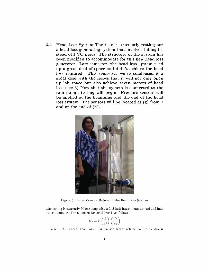
3.2 Head Loss System The team is currently testing outa head loss generating system that involves tubing in-stead of PVC pipes. The structure of the system hasbeen modi�ed to accommodate for this new head lossgenerator. Last semester, the head loss system usedup a great deal of space and didn't achieve the headloss required. This semester, we've condensed it agreat deal with the hopes that it will not only openup lab space but also achieve seven meters of headloss (see 3) Now that the system is connected to theram pump, testing will begin. Pressure sensors willbe applied at the beginning and the end of the headloss system. The sensors will be located at (g) from 1and at the end of (h).
Figure 3: Team Member Ruju with the Head Loss System
The tubing is currently 50 feet long with a 3/8 inch inner diameter and 1/2 inchouter diameter. The equation for head loss is as follows:
Hf = F
(L
D
)(V 2
2g
)where Hf is total head loss, F is friction factor related to the roughness
7
inside the pipe, L is the length of the pipe, D is the diameter of the pipe, Vis the average liquid velocity in the pipe, and g is the Universal GravitationalConstant (g = 9.81m
s2 ).As evident from the equation, head loss is directly proportional the the
length of the pipe. Since the tubing being used is coiled instead of straight,the team assumed that only the sections where the water is traveling upwardsshould be accounted for because in the downward sections, gravity is helpingthe water fall instead of the ram pump. This assumption was made becausethe ram pump should be pumping against gravity, but in these downwardssections the pumped water travels through the tubing with the help of gravity.However due to inadequate testing there is not enoughd data to verify or denythis assumption. Essentially, the e�ective length is close to the vertical heightof the coils multiplied by the number of coils. However, the exact performanceof the coiled tubes is unclear, because not only do we need to account for headloss in the tubes, we need to account for head loss where the tube curves andwhere it exits the air chamber. From last semester's experiments, water hasalso been observed to build up at the bottom of each pipe, which detracts fromthe e�ective length of the system. To remedy this, the team has angled thetubing to ensure that air is always present in each section of the pipe. Becauseof these uncertaities that are di�cult to account for, calculating the theoriticalhead loss is unreliable; therefore, head loss values should be measured directlyfrom EasyData and varied by changing the length of the tubing.
In conclusion, the head loss system is a new implement created by theAguaClara team and has not been robustly tested; as a result, the team willmostly rely on the actual pressure reading from the sensors and adjust the lengthof the piping until we each the desired head loss, and then continue to monitorthe sensor for a steady head loss generation.
3.3 Experimental Methods
The over head drive pipe was tested along with the the recycling system. Theteam also tested if water can be pumped from the water container (recyclingtank) on the �oor through the bent piping into the over head drive tank. Bytesting this section of the pump, via pumping water up from the recyclingcontainer to the overhead tank, the team realized that the ram pump was notready to be tested as the system experienced leaks and the piping connectionwas weak and had to be glued. Also, the system shakes due to inadequatesupport at the base. Adding some weight to the bottom of the structure willsolve the issue; however, this will have to be addressed by the next team.
Regarding the waste valve, it seemed like enough pressure wasn't being builtup in the system because the weight wasn't being pushed up/down as it should.The waste valve wasn't screwed in correctly due to some damaged threads, soanother part was ordered to ensure that the valve was straight.
8
4 Analysis
4.1 Issues
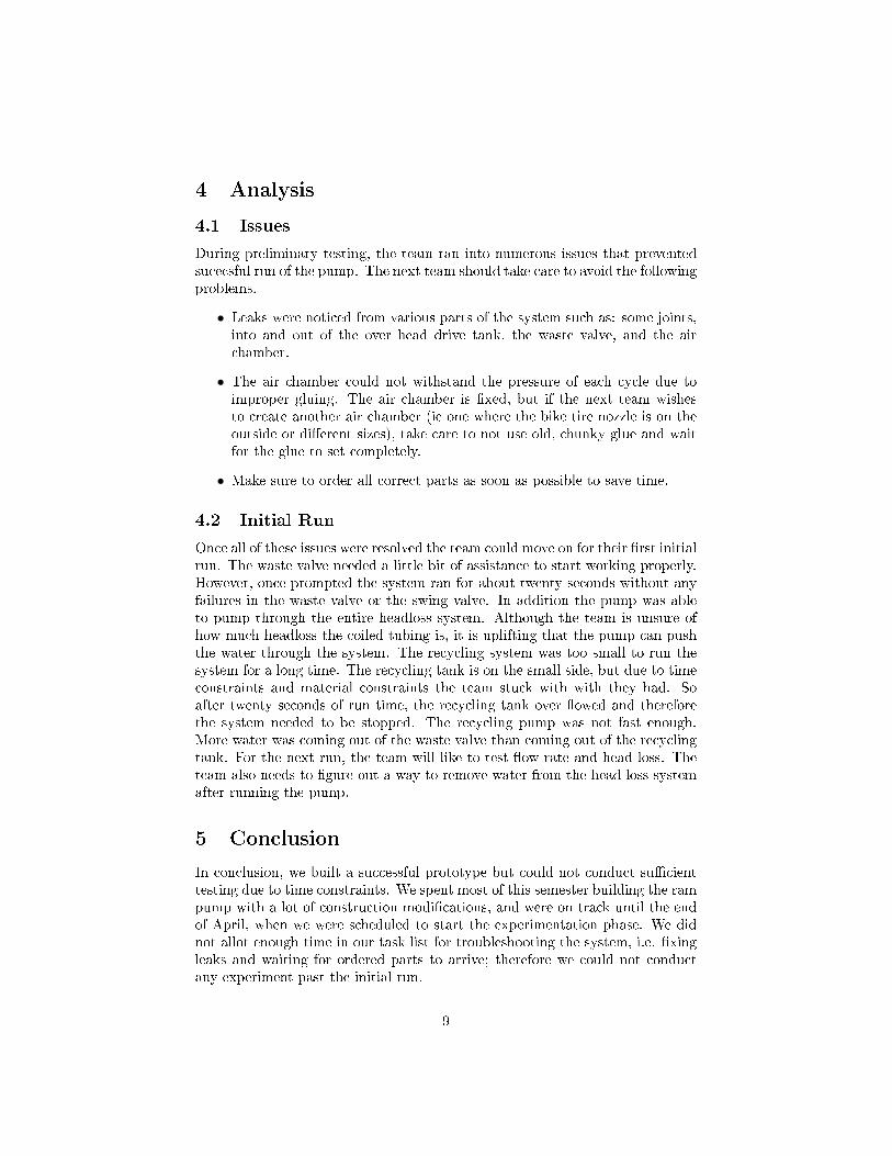
During preliminary testing, the team ran into numerous issues that preventedsucecsful run of the pump. The next team should take care to avoid the followingproblems.
• Leaks were noticed from various parts of the system such as: some joints,into and out of the over head drive tank, the waste valve, and the airchamber.
• The air chamber could not withstand the pressure of each cycle due toimproper gluing. The air chamber is �xed, but if the next team wishesto create another air chamber (ie one where the bike tire nozzle is on theoutside or di�erent sizes), take care to not use old, chunky glue and waitfor the glue to set completely.
• Make sure to order all correct parts as soon as possible to save time.
4.2 Initial Run
Once all of these issues were resolved the team could move on for their �rst initialrun. The waste valve needed a little bit of assistance to start working properly.However, once prompted the system ran for about twenty seconds without anyfailures in the waste valve or the swing valve. In addition the pump was ableto pump through the entire headloss system. Although the team is unsure ofhow much headloss the coiled tubing is, it is uplifting that the pump can pushthe water through the system. The recycling system was too small to run thesystem for a long time. The recycling tank is on the small side, but due to timeconstraints and material constraints the team stuck with with they had. Soafter twenty seconds of run time, the recycling tank over �owed and thereforethe system needed to be stopped. The recycling pump was not fast enough.More water was coming out of the waste valve than coming out of the recyclingtank. For the next run, the team will like to test �ow rate and head loss. Theteam also needs to �gure out a way to remove water from the head loss systemafter running the pump.
5 Conclusion
In conclusion, we built a successful prototype but could not conduct su�cienttesting due to time constraints. We spent most of this semester building the rampump with a lot of construction modi�cations, and were on track until the endof April, when we were scheduled to start the experimentation phase. We didnot allot enough time in our task list for troubleshooting the system, i.e. �xingleaks and waiting for ordered parts to arrive; therefore we could not conductany experiment past the initial run.
9
6 Future Work
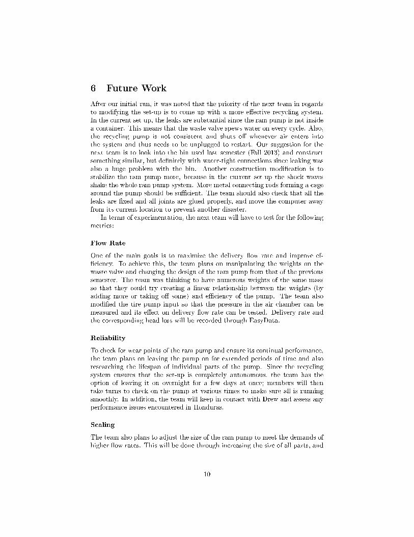
After our initial run, it was noted that the priority of the next team in regardsto modifying the set-up is to come up with a more e�ective recycling system.In the current set up, the leaks are substantial since the ram pump is not insidea container. This means that the waste valve spews water on every cycle. Also,the recycling pump is not consistent and shuts o� whenever air enters intothe system and thus needs to be unplugged to restart. Our suggestion for thenext team is to look into the bin used last semester (Fall 2013) and constructsomething similar, but de�nitely with water-tight connections since leaking wasalso a huge problem with the bin. Another construction modi�cation is tostabilize the ram pump more, because in the current set-up the shock wavesshake the whole ram pump system. More metal connecting rods forming a cagearound the pump should be su�cient. The team should also check that all theleaks are �xed and all joints are glued properly, and move the computer awayfrom its current location to prevent another disaster.
In terms of experimentation, the next team will have to test for the followingmetrics:
Flow Rate
One of the main goals is to maximize the delivery �ow rate and improve ef-�ciency. To achieve this, the team plans on manipulating the weights on thewaste valve and changing the design of the ram pump from that of the previoussemester. The team was thinking to have numerous weights of the same massso that they could try creating a linear relationship between the weights (byadding more or taking o� some) and e�ciency of the pump. The team alsomodi�ed the tire pump input so that the pressure in the air chamber can bemeasured and its e�ect on delivery �ow rate can be tested. Delivery rate andthe corresponding head loss will be recorded through EasyData.
Reliability
To check for wear points of the ram pump and ensure its continual performance,the team plans on leaving the pump on for extended periods of time and alsoresearching the lifespan of individual parts of the pump. Since the recyclingsystem ensures that the set-up is completely autonomous, the team has theoption of leaving it on overnight for a few days at once; members will thentake turns to check on the pump at various times to make sure all is runningsmoothly. In addition, the team will keep in contact with Drew and assess anyperformance issues encountered in Honduras.
Scaling
The team also plans to adjust the size of the ram pump to meet the demands ofhigher �ow rates. This will be done through increasing the size of all parts, and
10

a di�erent method than the overhead drive tank might be needed to simulatethe higher in�uent �ow rates.
References
11
Related Documents