1.General Shanghai Shenkai Petroleum & Chemical Equipment Co., Ltd (original Shanghai No. 1 Petroleum Machine Works) has a long history and strong technical strength to specialize in manufacturing petroleum equipment and tools. Our company owns the complete inspection, measure and test equipment. We have been awarded “Excellent Scientific and Technological Achievement Prize For Petroleum Equipment", “Second Prize of Science and Technical Progress Prize for Offshore Petroleum Equipment" and “First Prize of Science and Technical Progress Prize for Technical Study of BOP Control System " etc by original State Economy Commission, original Ministry of Machinery Industry and original China Petroleum & Gas Corporation. At present, the BOP stacks, which are manufactured by our company, have formed a product line to satisfy the need of land and offshore drilling platforms. 2FZ2870A shows : Double Ram BOP, Bore is φ279.4, rated working pressure is 70MPa, pressure- containing parts are castings , manual- lock,top and bottom flanged. FZ3570DY1B shows : Single Ram BOP, Bore is φ346.1 , rated working pressure is 70MPa, pressure- containing parts are forgings, axial hydraulic locking, top studded and bottom 《OPREATING MANUAL OF RAM BOP 》 1.1 Type Description: F Z New No.:E、F、G… Connection: A—top、bottom flanged B—top studded and bottom flanged C—top flanged and bottom studded D—top、bottom studded, omitted Y1 shows axial hydraulic locking, Y2 shows that radial hydraulic loc manual locking can be omitted. D shows that pressure- containing parts are forgings , steel casting can be omitted Shows the rated working pressure : e.g. “70” shows 70MPa Bore dimension: e.g. 28 shows that Bore is 279.4mm (11″) Ram BOP for short “ :FZ” Single Ram BOP-omitted ,Double Ram BOP -“2”,Triple Ram BOP“3” Example: -1-

Ram BOP Manual Book
Oct 25, 2015
Manual book for drilling
Welcome message from author
This document is posted to help you gain knowledge. Please leave a comment to let me know what you think about it! Share it to your friends and learn new things together.
Transcript
1.GeneralShanghai Shenkai Petroleum & Chemical Equipment Co., Ltd
(original Shanghai No. 1 Petroleum Machine Works) has a long history and strong technical strength to specialize in manufacturing petroleum equipment and tools. Our company owns the complete inspection, measure and test equipment. We have been awarded “Excellent Scientific and Technological Achievement Prize For Petroleum Equipment", “Second Prize of Science and Technical Progress Prize for Offshore Petroleum Equipment" and “First Prize of Science and Technical Progress Prize for Technical Study of BOP Control System " etc by original State Economy Commission, original Ministry of Machinery Industry and original China Petroleum & Gas Corporation. At present, the BOP stacks, which are manufactured by our company, have formed a product line to satisfy the need of land and offshore drilling platforms.
Our company has complete quality management system. The design and manufacture of product conform to API Spec 16A and national standard. We have obtained dual certificate quality system certification of API Spec Q1 and ISO 9001 as well as the license for using API monogram.
2FZ2870Ashows: Double Ram BOP, Bore is φ279.4, rated working pressure is
70MPa, pressure-containing parts are castings , manual-
lock,top and bottom flanged.
FZ3570DY1Bshows: Single Ram BOP, Bore is φ346.1, rated working pressure is
70MPa, pressure-containing parts are forgings, axial hydraulic locking, top studded and bottom flanged.
《OPREATING MANUAL OF RAM BOP 》
1.1 Type Description :
F Z
New No. :E 、F 、G…
Connection:
A—top 、 bottom flanged
B—top studded and bottom flanged
C—top flanged and bottom studded
D—top 、 bottom studded, omitted
Y1 shows axial hydraulic locking, Y2 shows that
radial hydraulic locking, manual locking can be
omitted.
D shows that pressure-containing parts are forgings, steel casting can be omitted
Shows the rated working pressure: e.g. “70” shows 70MPa
Bore dimension: e.g. 28 shows that Bore is 279.4mm (11″)
Ram BOP for short :“ FZ”
Single Ram BOP-omitted ,Double Ram BOP -“2” ,Triple Ram BOP“3”
Example:
-1-
1.2 ApplicationRam BOP with hydraulic control is a key part of well-control equipment. It’s used for
controlling wellhead pressure during drilling, workover and formation testing etc. to prevent well blowout effectively and realize safe construction. It can be used for the following(Figure 1): With proper pipe ram sealing the annular space between casing and tubular when there is
tubular in the wellbore. With blind ram sealing the wellhead completely when there is no tubular in the wellbore. When the well head is closed, using the kill manifold and choke manifold which are connected
to the spool and the side-outlet of the shell to perform special operations such as mud circulating, choking and releasing, well killing etc.;
If necessary, drilling tools can be hung with pipe ram. With shear rams shearing the drilling tools to seal the well in some special circs.

《OPREATING MANUAL OF RAM BOP 》
Figure 1 Installation of Ram BOP
2. Specification and Main Technical Data ( Table 1)
Connection and outside dimension(Figure 2 )
-2-
Annular BOP
Double Ram BOP
Drilling Spool
Single Ram BOP

《OPREATING MANUAL OF RAM BOP 》
-3-

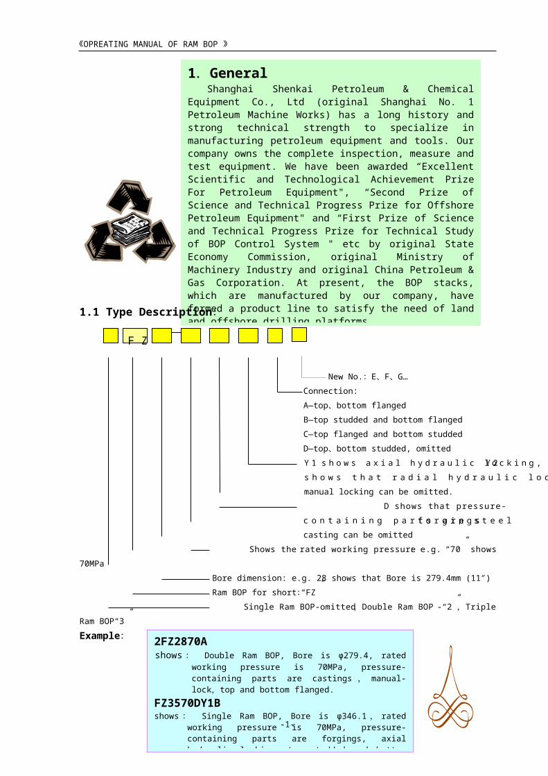
3. Working PrincipleRam BOP consists of some main parts such as
shell, side door, cylinder, piston, ram shaft, locking shaft, cylinder lid, and ram assembly and seals etc.(Figure 3)
《OPREATING MANUAL OF RAM BOP 》
-4-
3.2 Principle of SealingRam BOP has 4 sealing parts in order to seal the
wellhead effectively, i.e. the sealing between the ram top and shell, sealing between the front of ram and the pipe, sealing between the shell and the side door; sealing between ram shaft and the side-door. The sealing procedure of ram divides into 2 steps. First when closing the ram, ram shaft pushes ram by hydraulic oil to make front packing unit press to the sealing position so that seal off tubular or open-hole to form front sealing, over compression between the top packing unit and the sealing boss on shell forms top sealing and accomplishes initial sealing. Second when there is pressure in the well, it pushes the ram to press front packer further from back of ram to sealing position, at the same time, the ram rises against the sealing boss surface of shell, thus forming reliable sealing. This is called well pressure assisting sealing.
4.2 There are high supporting ribs and oblique plane for settling which slopes to the well bore at the bottom of the ram chamber of the shell, de-sanding automatically when opening and closing the ram to prevent blocking and reduce the friction of the ram. It is also helpful for well pressure assisting ram seal.
《OPREATING MANUAL OF RAM BOP 》
Figure 3 The Parts of Ram BOP
-5-
3.1 Principle of Opening and Closing OperationWhen high-pressure oil of hydraulic control
device is pumped into the closing chamber of left and right cylinder, it pushes the piston and ram shaft to make ram assembly to move to the center of wellhead along the orbit limited by the guide rid in the ram chamber to seal the well. When it is pumped into the opening chamber of left and right cylinder, it makes ram assembly move to leave the center to open the wellhead. The reversal valve of hydraulic control system controls the opening and closing of ram. The opening and closing acting force of ram is directly proportional to the stressed area of piston and the hydraulic pressure on this area.
4.Structure Features4.1 Main pressure-containing parts such as body and
side door are cast with high-quality alloy structural
steel. The materials conform to NACE MR-01-75,
apply to the working condition of acid medium and
have been specially heat-treated. The pressure-
containing parts have been performed the
hydrostatic proof test in accordance to the
specification of API Spec 16A to ensure safety
during operating under working pressure.
Blind Ram Assembly
Pipe Ram Assembly
Gasket Groove
Side Door
Locking ShaftRam Shaft
Locking Shaft Seal
Side Door Seal
Ram Shaft Seal
Cylinder Head
Cylinder
Side Door Bolt
Piston
Side Outlet

《OPREATING MANUAL OF RAM BOP 》
-6-
4.3 Using floating ram scaling can reduce the resistance force of opening & closing the ram and wearing of ram packer, prolong the service life of ram to prevent rusting between shell and ram and easy to disassemble.
4.4 There is a guide-block on the front end of ram, it
can be plugged in the groove of the opposite ram
and the chamber of guide-block can move drilling
tool toward the center of well bore during closing
rams to ensure reliable sealing between the ram and
drilling tool.
4.5 The BOP using the inner flow to avoid damaging the pipe during installing, transporting and operating.
4.7 In order to ensure to seal well safer and more reliable, there is a manual control device. If the control system of BOP is out of control, you can use the manual one to close the ram. If you want to seal well for a long time, then you can use manual control system to lock ram for that. (Figure 3 ) 4.10 the dimension of top, bottom and flange
outlet connection conform to Specification for Drilling Through Equipment API Spec 16A.
4.6 Load hinges are separated from the fluid hinges. The load hinges bear the weight of side-door. They are equipped with self-lubricated radial needle bearings and thrust bearings to open and close the side-door portably. The up and down positions of the side door can be adjusted with load hinges. Middle fluid hinges only connect oil lines and seal oil pressure, don’t bear the weight of side-door then prolong the seals service life. It also can replace seals directly on the shell without disassembling the side- door.(Except for FZ35-70、2FZ35-70)
4.8 When the rated working pressure is 105Mpa or
more, the sealing of the side-door uses floating
sealing assembly.
4.9 The sealing of ram shaft uses the lip type sealed junction.
5 Structure and feature of main part(s)5.1 Ram: Type S ram(figure 4)、Type HF ram(figure 5)、Type H ram(figure 6)
Type F ram(figure 7)、Variable ram(figure 6)、Shear ram(figure 8)

《OPREATING MANUAL OF RAM BOP 》
5.1.1 Type S Ram :
Figure 4 Type S Ram
Table2 Type S Ram Assembly Parts List
FZ28-35 2FZ28-35
Type S
No. 1 2 3 4 5
Description Assembly Ram Screw Holder Packer Screw Block
Quantity 2 1 1 2 1
Ram Size Part Number
27/8″DFZ2835-01B-
00
DFZ2835-01B-
05
DFZ2835-01B-
03
DFZ2835-01B. 01-
00
GB70-76
M12×60DFZ2835-01B-02
31/2″DFZ2835-01C-
00
DFZ2835-01B-
05
DFZ2835-01B-
03
DFZ2835-01C. 01-
00
GB70-76
M12×60DFZ2835-01C-02
41/2″DFZ2835-01D-
00
DFZ2835-01B-
05
DFZ2835-01B-
03
DFZ2835-01D. 01-
00
GB70-76
M12×60DFZ2835-01B-02
5″DFZ2835-01E-
00
DFZ2835-01B-
05
DFZ2835-01B-
03
DFZ2835-01E. 01-
00
GB70-76
M12×60DFZ2835-01E-02
7″ DFZ2835-01G- DFZ2835-01B- DFZ2835-01B- DFZ2835-01G. 01- GB70-76 DFZ2835-01G-02
-7-
5
4
2
1
3
Structure feature of Type S ram:(see figure 4)Top and bottom of ram are symmetric. When top surface of the ram packer has been worn seriously, the other
side can be used to prolong rubber life. Ram assembly consists of ram block, holder, packer and ram screw.Floating performance of the ram is good. Because the ram seat (ram holder) and the ram body (block) are
separated, the ram can move slightly in the holder to ensure positive alignment of the rubber faces as face seal contact occurs. There is 3mm installation clearance between the ram body and the ram seat. When shutting off the ram, the holder extrudes top rubber and makes it deform and bulge up to enhance effectiveness of sealing and reduces the wear of the ram packer.
For different dimensional drilling tools, only the corresponding sealing half ring and ram block (include blind ram) needs to replace, other parts are universal.
Procedure of replacing packer for Type S ramUnscrewing the two ram screws and take down the
holder.
Removing the two ram packer bolts.
Taking the top seal out from the groove of the ram block
with a screwdriver.
Remove the whole packer from the rams.
Before installation, cleaning the ram block, the packer
and ram screw and greasing them. The procedure of
assembling is in the opposite order. Pay attention to keep the
2mm~3mm design clearance between ram block and ram seat
when tightening the ram screws. Don’t push the top sealing
rubber out excessively to avoid wearing and scratching the
ram rubber rapidly.

《OPREATING MANUAL OF RAM BOP 》
00 05 03 00 M12×60
Blind RamDFZ2835-01H-
00
DFZ2835-01B-
05
DFZ2835-01B-
03
DFZ2835-01H. 01-
00
GB70-76
M12×60DFZ2835-01H-02
Table 3 Type S Ram Assembly Parts List
※
※ ※
※ ※
※ ※
※ ※
※ ※
5.1.2 Type HF Ram :
Figure 5 Type HF Ram
-8-
Be applicable to : FZ35-35 2FZ35-35 FZ35-70 2FZ35-70Type Type S No. 1 2 3 4 5Description Assembly Ram Screw Ram Holder Packer Screw BlockQty. 2 1 1 2 1Ram Size Part Number
27/8″ DFZ1310.01G-
00
DFZ1310.01A-
04
DFZ1310.01A-
02
DFZ1310.01G-01-00 GB70-76 M12×65 DFZ1310.01G-
02
31/2″ DFZ1310.01C-
00
DFZ1310.01A-
04
DFZ1310.01A-
02
DFZ1310.01C-01-00 GB70-76 M12×65 DFZ1310.01C-
02
41/2″ DFZ1310.01B-
00
DFZ1310.01A-
04
DFZ1310.01A-
02
DFZ1310.01B-01-00 GB70-76 M12×65 DFZ1310.01B-
02
5″ DFZ1310.01A-
00
DFZ1310.01A-
04
DFZ1310.01A-
02
DFZ1310.01A-01-00 GB70-76 M12×65 DFZ1310.01A-
02
51/2″ DFZ1310.01H-
00
DFZ1310.01A-
04
DFZ1310.01A-
02
DFZ1310.01H-01-00 GB70-76 M12×65 DFZ1310.01H-
02
7″ DFZ1310.01D-
00
DFZ1310.01A-
04
DFZ1310.01A-
02
DFZ1310.01D-01-00 GB70-76 M12×65 DFZ1310.01D-
02
95/8″ DFZ1310.01F-
00
DFZ1310.01A-
04
DFZ1310.01A-
02
DFZ1310.01F-01-00 GB70-76 M12×65 DFZ1310.01F-
02
Blind
Ram
DFZ1310.01E-
00
DFZ1310.01A-
04
DFZ1310.01A-
02
DFZ1310.01E-01-00 GB70-76 M12×65 DFZ1310.01E-
02
Structure feature:(figure 5)Ram assembly has an integral design.
The ram packer is composing seal. Ram assembly consists of ram block, face seal and top seal.
Its structure is simple and easy to disassemble.
Procedure of replacing packer for type HF ram:Prizing out the top seal and then face seal.
Smearing grease before the new installation.
Installing the front packing unit (pay attention
to the face direction) and then install the top
seal into the ram block.
1
2
3

《OPREATING MANUAL OF RAM BOP 》
Table 4 Type HF Ram Assembly Parts List
5.1.3 Type H Ram :
Figure 6 Type H Ram
-9-
FZ5414 2 FZ5414Type H FNo. 1 2 3
Description Assembly Top Seal Block Face SealQuantity 2 1 1Ram Size Part Number
5″ DFZ5414 . 47B-00 DFZ5414 . 47A. 03-00 DFZ5414 . 47B-01 DFZ5414 . 47B . 02-00
133/8″ DFZ5414 . 47C-00 DFZ5414 . 47A. 03-00 DFZ5414 . 47C-01 DFZ5414 . 47C . 02-00
Blind Ram DFZ5414 . 47A-00 DFZ5414 . 47A. 03-00 DFZ5414 . 47A-01 DFZ5414 . 47A . 02-00
Structure feature:(figure 6) The ram packing unit is single-face composing seal which the top seal and the front seal are
separated. Ram assembly consists of ram block, holder, face seal, top seal and ram screw. It reserves the advantage of good floating performance of Type s ram. Top seal and face seal that are separated can be replaced independently according to different
damage situation. So it’s easy to assemble and disassemble. For various size drilling tools, only need to replace corresponding front seal and ram block
including blind ram, other elements are universal.
Procedure for replacement, disassembly and assembly of packer:
Unscrewing the two ram screws, removing the holder.
Taking down the top packing unit.
Taking front packing unit out. Procedure for assembling is in
the opposite order (pay attention to direction of front packing unit’s end face). Installation requirements are the same as Type s ram.
4
5
3
2
1

《OPREATING MANUAL OF RAM BOP 》
Table 5 Type H Ram Assembly Parts List
5.1.4 Type F Ram:
Figure 7
Type F Ram
Ta
bl e
6
Ty
pe F
Ra
m
As
se m
bl y
Pa
rts
Li
st
-10-
FZ28-70 2FZ28-70Type Type H No. 1 2 3 4 5
Description Assembly Ram Screw Ram Holder Block Top seal Face sealQty. 2 1 1 1 1Size Part Number
23/8″2FZ2870. 02A-
00
2FZ2870. 02A-
04
2FZ2870. 02A-
03
2FZ2870. 02A-
02
2FZ2870. 02A-
05
2FZ2870. 02A. 01-
00
27/8″2FZ2870. 02B-
00
2FZ2870. 02A-
04
2FZ2870. 02A-
03
2FZ2870. 02B-
02
2FZ2870. 02A-
05
2FZ2870. 02B. 01-
00
31/2″2FZ2870. 02C-
00
2FZ2870. 02A-
04
2FZ2870. 02A-
03
2FZ2870. 02C-
02
2FZ2870. 02A-
05
2FZ2870. 02C. 01-
00
41/2″2FZ2870. 02D-
00
2FZ2870. 02A-
04
2FZ2870. 02A-
03
2FZ2870. 02D-
02
2FZ2870. 02A-
05
2FZ2870. 02D. 01-
00
5″2FZ2870. 02E-
00
2FZ2870. 02A-
04
2FZ2870. 02A-
03
2FZ2870. 02E-
02
2FZ2870. 02A-
05
2FZ2870. 02E. 01-
00
51/2″ 2FZ2870. 02F-002FZ2870. 02A-
04
2FZ2870. 02A-
032FZ2870. 02F-02
2FZ2870. 02A-
052FZ2870. 02F. 01-00
7″2FZ2870. 02G-
00
2FZ2870. 02A-
04
2FZ2870. 02A-
03
2FZ2870. 02G-
02
2FZ2870. 02A-
05
2FZ2870. 02G. 01-
00
Blind
Ram
2FZ2870. 02H-
00
2FZ2870. 02A-
04
2FZ2870. 02A-
03
2FZ2870. 02H-
02
2FZ2870. 02A-
05
2FZ2870. 02H. 01-
00
FZ23-35Type F
No. 1 2 3 4Description Assembly Compress block Packer Ram Screw Holder
Quantity 1 1 3 1Size Part Number
27/8″ F03-10A F03-09A F03-11A GB10-66 F03-10A-01
31/2″ F03-10B F03-09B F03-11B GB10-66 F03-10B-01
41/2″ F03-10C F03-09C F03-11C GB10-66 F03-10C-01
5″ F03-10D F03-09D F03-11D GB10-66 F03-10D-01
51/2″ F03-10E F03-09E F03-11E GB10-66 F03-10E-01
Blind Ram F03-38 F03-37 GB10-66 F03-36
Structure feature:(figure 7)Ram block has an integral design and simple
structure.
It’s easy to disassemble packer. Only the
screws need to unscrew.Procedure for replacement, disassembly and assembly of packer:
Unscrewing the No.3 screws, removing the No.1 compress block. If it’s difficult to remove, using copper stick to strike the holder.
Remove the No.2 packer.The procedure for assembling is in the
opposite order. Cleaning the holder and compress block and then greasing before installation.
3
1
2
4

《OPREATING MANUAL OF RAM BOP 》
5.1.5 Variable Bore Ram
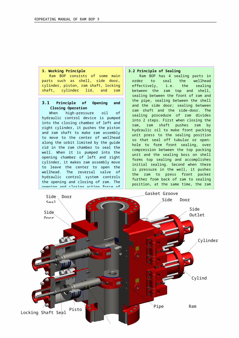
5.1.6 Shear Ram:(figure 8 )
Figure 8 Shear Ram
-11-
The function of shear ram:
When blowout is happening, shear ram can shear the tubular in the well in order to shut in the well completely. It also can be used as blind ram in working order.
Type F35-70 ram BOP, is equipped with type SR3570 shear ram assembly which can shear 5 inch 19.5lb/ft Grade S ( 135 ) drill pipe and completely shut in the well.
Some Bops are equipped with variable bore ram, which can replace ram without opening BOP to seal different size drilling tools in specified range. At present, we provide 3-1/2″~5 ″(13-5/8″-70Mpa),its structural form is H(figure
6). Disassembly, assembly and replacement of packer are the same as Type H ram.
1 2 3 4 5 6 7 8 9 10 11
12
13
《OPREATING MANUAL OF RAM BOP 》
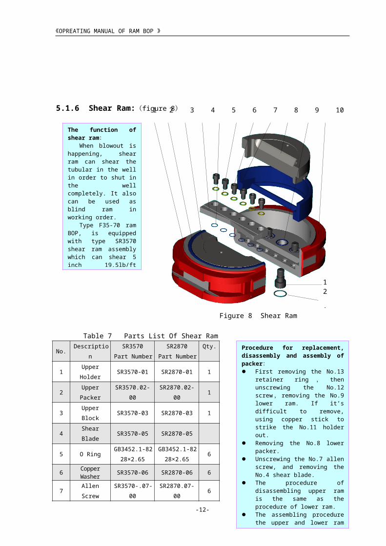
Table 7 Parts List Of Shear Ram
No. DescriptionSR3570
Part Number
SR2870
Part Number
Qty.
1Upper
HolderSR3570-01 SR2870-01 1
2Upper
PackerSR3570.02-00
SR2870.02-
001
3 Upper Block SR3570-03 SR2870-03 1
4 Shear Blade SR3570-05 SR2870-05
5 O RingGB3452.1-82
28×2.65
GB3452.1-
82
28×2.65
6
6 Copper Washer SR3570-06 SR2870-06 6
7 Allen ScrewSR3570-.07-
00
SR2870.07-
006
8Lower
PackerSR3570.09-00
SR2870.09-
001
9Lower
BlockSR3570-08 SR2870-08 1
10 O RingGB3452.1-82
51.5×5.3
GB3452.1-
82
48.7×5.3
6
11Lower
HolderSR3570-10 SR2870-10 1
12 Screw SR3570.04-00SR2870.04-
006
13Retainer
Ring
GB893.1-86
φ63
GB893.1-86
φ626
5.2 Ram Manual-lock System
-12-
All ram BOPs are equipped with manual-lock system. Manual-lock system closes and locks the ram by the
handwheel, it consists of locking shaft, ram shaft, manual-operated rod and handwheel etc.(Figure 9)Its functions as follows: when hydraulic system is out of service rams can be closed by manual system in
time to seal well head; when need to seal well for a long time, locking rams at closing position after closing ram
with hydraulic pressure. At this point, the hydraulic pressure can be relieved. Turn the hand wheel right to drive
the locking shaft rotating through operating rod. Because the locking shaft shoulder presses against the cylinder
lid, it can’t go back, thus it can only drive the ram shaft to move toward the wellhead center and locking the rams.
Note:Manual-lock system can only
close the rams, not open. If you want
to open the rams closed by manual
system, you must unlock the system to
original position and then open the ram
with hydraulic pressure. It is the only
method to open rams, the operation
procedure as following:
Turning the hand wheel left until
end, then turn back 1/8~1/4 circle
to avoid the locking shaft is
blocked at the unlocking position
when the temperature changes.
Opening the rams with hydraulic
pressure.
Procedure for replacement, disassembly and assembly of packer: First removing the No.13 retainer
ring , then unscrewing the No.12
screw , removing the No.9 lower ram. If it’s difficult to remove, using copper stick to strike the No.11 holder out.
Removing the No.8 lower packer. Unscrewing the No.7 allen screw, and
removing the No.4 shear blade. The procedure of disassembling
upper ram is the same as the procedure of lower ram.
The assembling procedure the upper and lower ram is in the opposite order. Cleaning and greasing each part before installation.

1
2
3
《OPREATING MANUAL OF RAM BOP 》
Figure 9 Ram manual-lock system
5.3 Side Door Seal System
Table 8 Floating Sealing Parts List
Figure 10 Floating seal system
5.4 Hydraulic automatic locking equipment:
-13-
Be applicable to :FZ35105
2FZ35105
FZ28105
2FZ28105
No. Description Quantity Part Number
1 Framework 1 2FZ35105A.03-01 FZ2870X-08-12
2 Upper Seal Ring 1 GB3452.1-82 487×7 FZ2870-D-02-07
3 Door Seal Ring 2 2FZ35105A.03-10 GB1235-76 460×5.7
5.4.1 Axial hydraulic automatic locking equipment: Principle: Axial hydraulic automatic locking equipment is operated through locking piston installed in main-piston and four locking blocks installed in piston radial four-sector grooves. (See Fig 11). When hydraulic oil acts on the closing chamber, it forces main-piston and locking piston to move toward the direction of closing ram. Because there are chamfers on the locking block’s inside and outside circles, inside chamfers contact with locking piston chamfers to make the locking piston pushes the block. It always has the trend of moving forth. Once main-piston reaches the closing position, locking block will move 7mm forth by the action of locking piston’s axial supporting force and sit cylinder’s step, the locking block’s outside chamfer contacts with the chamfer of cylinder’s step. Now the locking piston moves ahead further and contacts with circle through inside diameter of locking block to lock completely. Ram shaft brings along display rod to move toward inside and shrink into cylinder lid. If you want to open the ram, only hydraulic oil acts on opening chamber to make locking piston move forth firstly, component of forces produced by the chamfer of locking block’s outside circle and cylinder step and make locking block shrink toward inside to unlock, then main-piston brings along ram shaft and ram to open. At the same time ram, shaft pushes display rod to put out cylinder lid.
When the rated working pressure is more than 70MPa, the side-door sealing uses
advanced floating seal system(Fig 10、Table 8). It can make the side-door stud’s torque is
less than general side-door sealing about 20%~30% to ensure the reliable sealing when it
works. The labour strength is also obviously decline when we open the side door.
When the rated working pressure is 70MPa or less, the steel grouping seal ring is used to
seal the side-door.

《OPREATING MANUAL OF RAM BOP 》
图7 轴向液压自动锁紧装置Figure 11 Axial hydraulic automatic locking equipment
-14-
Debugging Method:Hydraulic locking location has been debugged well before leaving factory. It still needs
to be debugged at site. When locking position is adjusted because of kinds of reasons, the piston’s both ends must be adjusted at the same time. Each circle is 4mm and the least quantities of adjusting is 2/3mm. When locking is over the position and journey is not enough, reversing main-piston to adjust. When locking is not at the position, turning the main-piston to adjust. Under normal condition, the distance of ram’s end faces is less than 4mm after relieving oil pressure. If the distance is more than 4mm, it shows that locking is not in the proper position. Normally piston is adjusted to the position where ram is sealed after locking before leaving factory, so it leaves enough stroke. When repairing and adjusting again, piston should be screwed into the ram shaft. After ensuring to be tightened completely, reversing the main-piston to make it back off 1½~12/3 circles. It is dertermined according to the position of piston end cover’s hexagonal hole and bolthole. After adjusting piston’s position, piston end cover should be tightened. Display rod and display block are used specially at the opening and closing position of automatic display ram to avoid misoperation. The bulgy display block shows opening and the concave one shows closing.
5.4.2 Radial Hydraulic Automatic Locking System: Principle:
Radial hydraulic automatic locking system pushes the dowel pin to lock the ram shaft (figure 12) by oil pressure in the locking cylinder, which is installed behind the main cylinder and is perpendicular to the ram shaft. Since the oil piping of both the locking cylinder and the main cylinder are parallel, dowel pin will lock the ram shaft automatically when closing the ram. Because the incline angle can lock by itself, the ram won’t loose along the ram shaft if there is no oil pressure to push the locking cylinder to unlock.
Only hydraulic pressure can open the ram. At first, unlocking the locking cylinder, the ram shaft goes back and crosses the hole in the middle of dowel pin, then makes the ram open completely. The above opening and closing of ram, locking and unlocking is synchronous with the opening and closing of ram. Needn’t other operation.
In order to confirm whether the ram is locked, there is a display device on this radial hydraulic locking system. It separately displays the position of dowel pin and ram shaft. When the ram is locked, two displays don’t bulge. When locking and opening the ram, the two displays bulge.
locking block main-piston locking piston display rod

《OPREATING MANUAL OF RAM BOP 》
Figure 12 Radial Hydraulic Automatic Locking System
5.5 Ram Shaft Seal Structure and Ram Shaft Secondary Seal System
-15-
Debug:Normally, hydraulic locking location has been
debugged before leaving factory. If the ram is worn lightly after using, repairing the chamfers of ram shaft tail and dowel pin.
Seal structure of ram shaft are double directions seal to prevent medium in well flowing into the hydraulic oil which protects hydraulic oil from being polluted and leaked, and reduces the wear of pump-valve element. The secondary seal system is installed at ram shaft, when medium in well leaks out from the weep-hole; the normal seal failed and shall apply secondary seal to remedy. Unscrew the plug in secondary seal hole, clockwise turn the piston screw with proper tool, force the lower clubbed plastics seal grease into the sealing surface through the radial hole of the separation copper case, forming the forced seal. Inject the seal grease until nothing leaks out from the weep hole, the capacity of injection should not be over, and otherwise it will increase the wear of ram shaft and the resistance of opening and closing ram. If the hydraulic oil in the cylinder leaks out from the weep hole, the sealing element in the ram shaft cylinder has failed, the sealing element shall be changed.
Main cylinder Ram shaft Dowel pin Locking cylinder
Display device

4
6
5
8
7
11
10
《OPREATING MANUAL OF RAM BOP 》
Table 9 FZ35105 Ram Shaft Seal Assembly
Figure 13 FZ35105 Ram Shaft Seal Structure
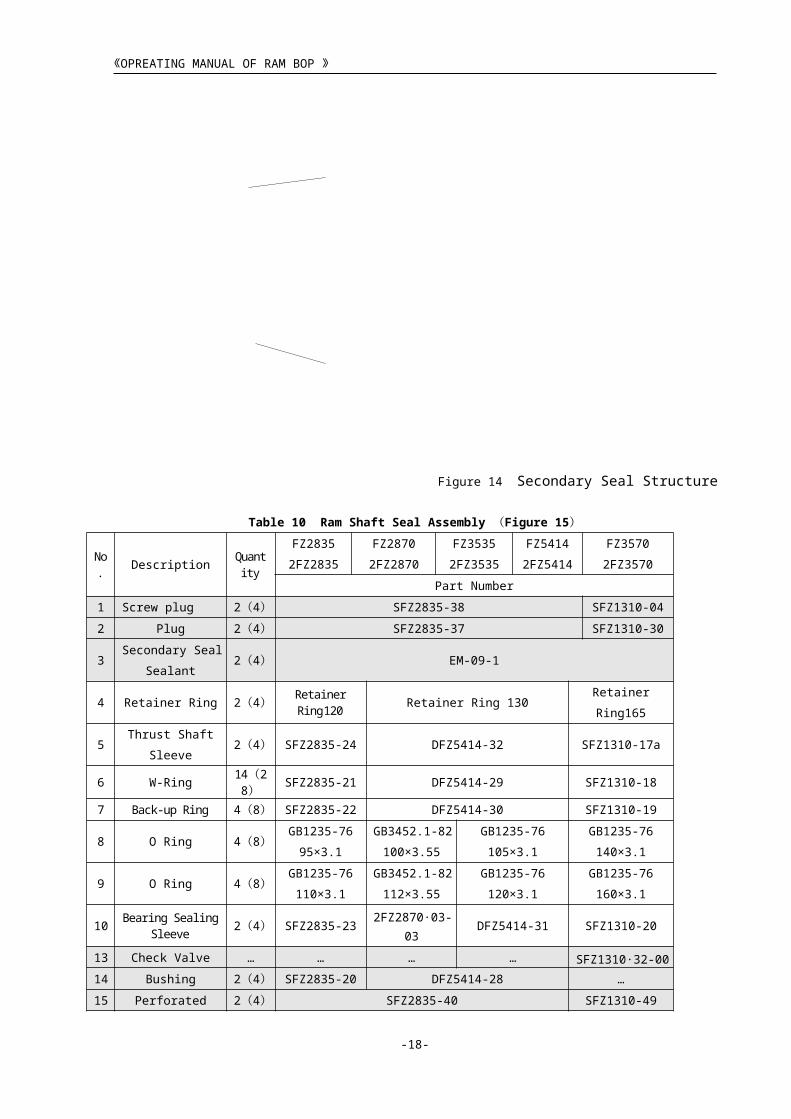
Figure 14 Secondary Seal Structure
Table 10 Ram Shaft Seal Assembly (Figure 15 )
No.
Description Quantity
FZ2835
2FZ2835
FZ2870
2FZ2870
FZ3535
2FZ3535
FZ5414
2FZ541
4
FZ3570
2FZ3570
Part Number
1 Screw plug
2
( 4
)
SFZ2835-38 SFZ1310-04
2 Plug 2 SFZ2835-37 SFZ1310-30
-16-
No. Description Quantity Part Number
1 Plug 2(4) SFZ1310-04
2 Sec. Seal Plug 2(4) SFZ1310-30
3 Sealant. Sec. Seal 2(4) EM-09-1
4 Retainer Ring 2(4) SFZ1310-48a
5 Packing Washer 2(4) 2FZ35105A.03-12
6 Wiper Ring 2(4) 2FZ35105A.03-11
7 Lip Ring (front) 2(4) FZ2870X-08-19
8 Lip Ring (cover) 4(8) FZ2870X-08-18
9 Lip Ring (back) 2(4) FZ2870X-08-21
10 O Seal Ring 4(8) GB3452.1-82150×3.55
11 O Seal Ring 4(8) GB3452.1-82136×3.55
12 Packing Bearing Ring 2(4) SFZ1310-20
13 Check Valve 2(4) SFZ1310.32-00
14 Bushing 2(4) 2FZ35105A.03-13
15 Perforated Plug 2(4) SFZ1310-49Note: Quantities shown for single-ram BOP. Quantities in
the parentheses show for double-ram BOP.
The secondary seal is only used as an emergency measure if there is serious leakage at the sealing position of the ram shaft. If possible, the ram shaft seals shall be replaced at once The secondary seal can’t be used to contain the well pressure for a long time.(Figure 14)
14 9 12
1
2
3
13

《OPREATING MANUAL OF RAM BOP 》
( 4
)
3Secondary Seal
Sealant
2
( 4
)
EM-09-1
4 Retainer Ring
2
( 4
)
Retainer Ring120 Retainer Ring 130Retainer
Ring165
5Thrust Shaft
Sleeve
2
( 4
)
SFZ2835-24 DFZ5414-32 SFZ1310-17a
6 W-Ring14(28
)SFZ2835-21 DFZ5414-29 SFZ1310-18
7 Back-up Ring
4
( 8
)
SFZ2835-22 DFZ5414-30 SFZ1310-19
8 O Ring
4
( 8
)
GB1235-76
95×3.1
GB3452.1-82
100×3.55
GB1235-76
105×3.1
GB1235-76
140×3.1
9 O Ring
4
( 8
)
GB1235-76
110×3.1
GB3452.1-82
112×3.55
GB1235-76
120×3.1
GB1235-76
160×3.1
10 Bearing Sealing Sleeve
2
( 4
)
SFZ2835-232FZ2870.03-
03DFZ5414-31 SFZ1310-20
13 Check Valve … … … … SFZ1310.32-00
14 Bushing
2
( 4
)
SFZ2835-20 DFZ5414-28 …
15 Perforated Plug
2
( 4
)
SFZ2835-40 SFZ1310-49
Note: Quantities shown for single-ram Bop. Quantities in the parentheses show for double-ram BOP.
-17-
《OPREATING MANUAL OF RAM BOP 》
Table11 FZ28105 Ram Shaft Seal Assembly (Figure 16)
Ram Shaft Seal Parts (Fig 15)
FZ28105 Ram Shaft Seal Parts (Fig 16)
5.6 Locking Shaft Seal Structure
-18-
No. Description
Quantity Part Number
1 Plug2 ( 4
)SFZ1310-04
2 Secondary Seal Plug2 ( 4
)SFZ1310-30
3 Sec. Seal Sealant 2 ( 4
)EM-09-1
4 Retainer Ring4 ( 8
)SFZ1310-48a
5 Seat Retainer 2 ( 4
)FZ2870X-08-17
6 Wiper Ring2 ( 4
)FZ2870X-08-16
7 Lip ring (front)2 ( 4
)FZ2870X-08-19
8 Lip ring (cover)6( 12
)FZ2870X-08-18
9 Lip ring (back)4 ( 8
)FZ2870X-08-21
10 Washer2 ( 4
)FZ28105A-03-02
11 Packing Bearing Ring2 ( 4
)SFZ1310-20
13 Check Valve2 ( 4
) SFZ1310.32-00
14 Baffle Ring2 ( 4
)FZ2870X-08-22
15 Perforated Plug2 ( 4
)SFZ1310-49
Note: Quantities show for single-ram Bop. Quantities in the parentheses show for double-ram BOP.
45
67
510
9
456
78
11
149
10

1
2
3
4
6
5
《OPREATING MANUAL OF RAM BOP 》
Figure 17 Locking Shaft Seal
Table 13 Locking Shaft Seal Assembly
Be applicable to :
FZ2835
2FZ2835
FZ3570
2FZ3570
FZ35105
2FZ35105
FZ3535
2FZ3535
FZ2870
2FZ2870
FZ5414
2FZ5414
Item DescriptionQuantit
yPart Number
1 Retainer Ring2 ( 4
)Retainer Ring 95
2Thrust Shaft
Sleeve
2 ( 4
)SFZ1310-21
2FZ3535-
17ADFZ5414-26
3 W-ring6 ( 12
)SFZ2835-18 DFZ5414-25
4 Back –up ring2 ( 4
)SFZ2835-17 DFZ5414-24
5Wiper Seat
Retainer
2 ( 4
)SFZ1310-22 DFZ5414-23
6 Wiper Ring2 ( 4
)SFZ1310-23 DFZ5414-22
-19-
The locking shaft seal is installed on the cylinder lip to prevent the hydraulic oil from leaking out and the dust from entering the cylinder.(Figure 17、Table 13)

《OPREATING MANUAL OF RAM BOP 》
Note: Quantities show for single-ram Bop. Quantities in the parentheses show for double-ram BOP.
5.7 Hinge Structure Table 13 Hinge Bracket Assembly(FZ35105 )
Figure 19 Type B Hinge Structure
Figure 18 Type A Hinge Structure
-20-
No. Description Quantity Part Number1 Hinge Pin 4(8) 2FZ2870.01-012 O Ring 4(8) GB3452.1-82 63×3.55
3 Hinge (2) 2(4) 2FZ35105A.06.01-004 O Ring 12(24) GB3452.1-82 48.7×3.55
5 Hinge Bracket (1) 4(8) 2FZ35105A.06-02
6 Bearing 4(8) GB301-64 8107
7 Adjusting gasket 8(16) 2FZ2870.01-048 Needle Bearing 4(8) GB290-64 941/30
9 O Ring 4(8) GB3452.1-82 20×2.65
10 O Ring 4(8) GB3452.1-82 33.5×3.55
11 Hydraulic Connection 4(8) 2FZ35105A.06-0312 Spring 4(8) 2FZ2870.01-06
13 Hinge Bracket (2) 2(4) 2FZ35105A.12.01-00
2FZ35105A.06.04-0014 Hinge (1) 2(4) 2FZ35105A.06.05-00
Note: Quantities show for single-ram Bop. Quantities in the parentheses show for double-ram BOP.
Type A Hinge Structure ( Figure
18):Side-door hinge is designed that the load hinge is separated from the hydraulic hinge. This structure has following features:
1. Load hinges bear the full weight of
side-doors; self-lubricated radial needle
bearing and sliding step bearing are
installed on it so that opening and
closing the doors protably.
2. The middle hydraulic fluid hinges only connect oil pipe and seal oil pressure. They don’t bear the weight of the side door. That can prolong the life of packing. The packing can be replaced directly on the body without disassembling the side door. 3. The upper and lower position of side door can be adjusted with load hinges.
1
2
4
356

《OPREATING MANUAL OF RAM BOP 》
Table 14 Hinge Bracket Assembly
Be applicable to:FZ2835
2FZ2835
FZ2870
2FZ2870
FZ3535
2FZ3535
FZ5414
2FZ5414
序
号
Description Qty.Part Number
1 Hinge (2) 2
(
4
)
SFZ2835.30-
00
2FZ2870.01.08-00 2FZ3535.11.07-00 DFZ5414.02-
00
2 Hydraulic
Hinge
Bracket (2)
2
(
4
)
SFZ2835-33 2FZ2870.11.01-
00(right)
2FZ2870.01.07-00(left)
2FZ3535.12.01-
00(right)
2FZ3535.11.02-
00(left)
DFZ5414-50
3 Spring 4
(
8
)
SFZ2835-31 2FZ2870.01-06 2FZ3535.11-03 SFZ2835-31
4 Hydraulic
Connection
4
(
8
)
SFZ2835-32 2FZ2870.01-05 2FZ3535.11-04 DFZ5414-37
5 O Ring 4
(
8
)
GB1235-76
35×3.1
GB3452.1-82
33.5×3.55
GB1235-76
40×3.1
GB1235-76
30×3.1
6 O Ring 4
(
8
)
GB1235-76
25×3.1
GB3452.1-82
20×2.65
GB1235-76
25×2.4
GB1235-76
30×3.1
7 Needle
Bearing
4
(
8
)
GB290-64
941/35
GB290-64
941/30
GB290-64
941/30
GB290-64
942/30
8 Adjusting
Gasket
8
(
16
)
… 2FZ2870.01-04 2FZ3535.11-05 …
9 Single Thrust
Bearing
4
(
8
)
… GB301-64 8107 GB301-64 8107 …
-21-

《OPREATING MANUAL OF RAM BOP 》
10 Hinge
Bracket
4
(
8
)
SFZ2835-29 2FZ2870.01-03 2FZ3535.11-05 DFZ5414-05
11 O Ring 8
(
16
)
GB1235-76
50×3.1
GB3452.1-82
48.7×3.55
GB1235-76
55×3.1
GB1235-76
60×3.1
12 Hinge (1) 2
(
4
)
SFZ2835.26-
00
2FZ2870.01.08-00 2FZ3535.11.01-00 DFZ5414.01-
00
13 O Ring 4
(
8
)
GB1235-76
63×3.1
GB3452.1-82
63×3.55
GB1235-76
70×3.1
GB1235-76
68×3.1
14 Hinge Pin 4
(
8
)
SFZ2835-28 2FZ2870.01-01 2FZ3535.11-08 DFZ5414-03
15 O Ring 4
(
8
)
GB1235-76
45×3.1
GB3452.1-82
48.7×3.55
GB1235-76
55×3.1
GB1235-76
45×3.1
Note: Quantities show for single-ram BOP. Quantities in the parentheses show for double-ram BOP.
Figure 15 Type B Hinge Structure Part List
Be applicable to: FZ3570 2FZ3570
N
o.
Descripti
onQty. Part Number
1 Plug4 ( 8
)SFZ1310-04
2Hinge Pin
2 ( 4
)SFZ1310-03
3Oil Cup
2 ( 4
)GB1152-79 M10×1
4Hinge Bracket
2 ( 4
)SFZ1310-05 ( L ) SFZ1310-
40(R )5
Side-door2 ( 4
)SFZ1310-26 ( L ) SFZ1310-
41(R )6 O Ring 16( 32 GB1235-76 60×5.7
-22-
Type B Hinge Structure(Fig 19):Side door hinge is connected with
side door, long hinge pin goes through the top and bottom hinge (Fig 19) . The route of hydraulic oil to be pumped into the cylinder as following:Hinge bracket end holeHinge pinHinge Side door buried oil wayOil pipe(cylinder)Cylinder lidCylinderThe “O” seal rings are used on all oil pipe.

《OPREATING MANUAL OF RAM BOP 》
)Note: Quantities show for single-ram BOP. Quantities in the parentheses
show for double-ram BOP.
6. Installation Operation
7. Operation and Notice
-23-
6.1 Installation: Ram BOP shall be performed sealing pressure
test under rated working pressure before using
and be transported to well site.
Installation should be according to well control
specification requirements of BOP combination
form.
Installation orientation should be: The hand
wheel and actuating arm of manual-lock system
should be located at the both sides of the derrick
window. The outlet for the flange of the body
should face the window in order to observe the
leakage of the discharge opening of ram shaft
packing.
Manual-lock system shall be fully installed and
fixed. Put a card on the hand wheel to make the
number of turns for opening and closing circles.
The size of ram equipped in the BOP must
correspond with the size of drill tool used during
drilling. Mark the ram size on the driller’s station
and remote control console to avoid from wrong
installation.
6.2 Pressure Test Running after Installation:
The installed ram BOP and the whole set of
wellbore equipment are performed hydrostatic
proof pressure test for inspecting the reliability of
all connections and the seal characteristics; it can
be used if it is qualified.
Each ram should be checked by closing and
opening twice on the driller’s station and remote
control console to inspect correspondence
between opening & closing and practical
operation and correctness of lines connections.
And air should be removed from the oil duct.
Try to close and lock the rams with test the
manual lock system for inspecting their
flexibility and reliability. Note that manual–lock
system can only close the rams, but cannot open
them. If you want to open them you must unlock
the system manually and then open the ram with
hydraulic pressure. Before manually closing, the
corresponding hydraulic control valves must be
turned to their “closing” position. When locking
and unlocking, turning the hand wheel to reach
the designated position, then turning back
1/8~1/4 circle, and making the number of turns
for the hand-wheel.7.1 The ram BOP is used to seal off the drill’s tool,
which has the same size as pipe ram to seal the open
hole during the blowout. If need to close the well for
a long time, the ram should be locked with manual
locking system. The situations of locking opening
and closing shall be marked to prevent wrong
operation.
7.3 Relieving well pressure by opening ram is
prohibited. Before opening ram BOP, checking if the
manual-lock system is unlocked. And then, check if
the is fully opened (fall back to the body) and it
cannot stay in the middle position to prevent ram
from drilling tool bumping.
7.2 When opening or closing side door, the
oil pressure of control mainfold should be relieved
to protect the O-ring of the hinge axis. Opening
and closing ram is not permitted if the side door
bolt is loose to protect ram, ram shaft and hinge
from damaging. For protecting wellhead, no
matter ram BOP is fixed on wellhead flange or not.
The two side doors cannot be opened
simultaneously.7.4 Only there is serious leakage at the sealing
position of the ram shaft, the secondary seal
system is used to inject the seal grease when
emergency. The injection rate should not be
overmuch. So that prevents the ram shaft and the
seals from damaging. If possible, the ram shaft
seals should be replaced at once. The secondary
seal can’t be used to contain the well pressure for a
long time.
7.5 When there is drilling tool in the well, prohibit closing the blind ram.
7.6 After reaching the target stratum, the pipe rams should be opened and closed one day to check if they are flexible. After the drill string is pulled out of the hole, the blind ram should be checked whether it’s opening and closing is flexible, and also the manual lock system.
7.7 When the rams cannot be closed or opened under the normal control pressure, you can treat it base on the serious analyzing. If necessary, when you can open the bypass valve of control system mainfold to increase the pressure and directly using 21MPa of accumulator to control it. Under the special circumstance, using gas-fluid pump to inflate directly to 31.5MPa to control it. Before using the high pressure, the stop valve of an accumulator should be turned off and cannot be used for a long time.

《OPREATING MANUAL OF RAM BOP 》
8. Maintenance
-24-
7.9 At least one set of ram which has the same size as the being used ram should be prepared at well site to replace the damaged ram in time.
7.10 Note: Keep hydraulic oil clean.
7.8 After using BOP, keeping BOP ram opening fully for repairing and maintaining.
8.1 Notice:
After using the well, disassembling the hydraulic lines of ram BOP and blocking
off bore with bottom sub. Cleaning the outside of BOP and the inner chamber of
ram and greasing bolt hole, gasket groove, top sealing boss of ram, bottom and
side support and guide ribs, side-door hinge with water-proof butter to prevent
from rusting.
Gathering and encasing the connections such as gasket, studs, nuts and special
tools to prevent them from losing.
Checking the all screws frequently. Tightening them in timely if they are loose.
Keep hydraulic oil clean and prevent dirt from entering into the cylinder, which
avoid damaging cylinder and piston.8.2 All rubber spare parts should be stored reasonably as following: Numbering them according to the
time of warehousing and always using the oldest one first.
Rubber must be stored in a relaxtional state in a dark and dry room, prohibit storing them in the open air. Rubber cannot be compressed. It is better to lay the rubber flat in a wooden case. O-ring cannot be hung on the woodpile.
Rubber cannot contact corrosive medium, keeping away from electric motor and high voltage equipment to avoid producing ozone to corrode rubber.
8.3 Replacement of ram assembly and ram
packing unit:
Ram assembly and ram packing unit are the key parts
sealing well in a BOP. If it is damaged, BOP can’t
seal well. So it is very important to keep it well and
replacing it in time if it is damaged. Procedures of
ram rubber replacement as follow:
Opening the ram completely with hydraulic oil.
Unscrewing the coupling bolts of the side door.
Note when BOP is installed on well the bolt
cannot be unscrewed if there is pressure in hole.
Pulling ram assembly out from ram shaft head.
The replacement of ram packer refers to 5.1 the
replacement of ram assembly.
8.4 Repair and replacement of oil cylinder
assembly:
Procedures of cylinder assembly disassembly:
Opening the rams completely with hydraulic
pressure first. If side door is in opened state,
closing side door and at least screwing a bolt
at the opposite side of hinge bracket.
Putting a clean oil pan under cylinder to
prevent oil from flowing to ground.
Unscrewing the studs and nuts of cylinder lid,
removing cylinder lid, taking retainer ring and
locking shaft-sealing ring out from cylinder
cover.
Removing the locking shaft.(see fig 9 Ram
Locking Structure)
Removing cylinder.
Unscrewing the backing-up screw in piston
locking out.
Unscrewing the locking nut and striking
piston out lightly.
Opening side door, taking off ram, and pulling
out piston rod (ram shaft).
Removing retainer ring and taking out ram
shaft sealing ring.

《OPREATING MANUAL OF RAM BOP 》
Fig 20 Structure of Piston Locking Sealing
Table 16 The reasons and settlements of malfunctions
N
o.Malfunction Cause Settlement
1 The medium in the well
flows out from the
connection between the
shell and side-door.
Sealing ring between the
shell and side door is
damaged.
Coupling bolts between the
shell and side-door are
loose.
There is dirt or damage on
the shell and side seal
surface of the shell and side-
door.
Replacing damaged seal
ring.
Tightening all coupling
bolts.
Clean the surface and
repairing damaged parts.
2 The movement direction
of ram is not conforming
to nameplate mark of
The pipelines between
control console and BOP
have been connected
Exchanging pipelines
that connect BOP.
-25-
8.5 Checking and repair after cylinder disassembly
Inner wall of cylinder
When wearing of cylinder’s I.D. exceeds the
limited 0.4mm or there is serious vertical scratch and
coating peeling off in cylinder inner wall, it cannot
prevent oil from leaking even if replacing a new piston
seal ring. It should be changed with a new cylinder. At
the same time, checking relative parts such as piston and
finding out scratching reasons and solving the troubles.
If scratch is shallow wirelike or punctate, repairing them
with abrasive paper and oilstone.
The O.D. of sealing surface of ram shaft and
locking shaft
When there is scratch on the sealing surface, using
the same inspection and treatment method as the
cylinder. If coating peeling off, they must be replaced
with the new parts.
Sealing ring
Checking the edges of seals whether there are wear
and tear, scar and aging first. If they exist, the seals
should be replaced.
Piston
When outer diameter wearing exceeds the limited
tolerance 0.25 mm, it should be repaired or changed.
8.6 Installation of cylinder assembly:
Installation steps are according to reversal
disassembly steps of it. But note the following
items:
Check them if there are burrs or cusped edges
on parts. If they exist, removing them to
prevent the edge of seal ring from scratching.
Keep parts clean.
When installing seal ring, greasing the surface
of and also the inside and outside sealing
surface of matched parts for easy assembly.
Take care lip sealing ring’s direction; ensure
the opening of lip against pressure side. Let
sealing ring passing through thread part
smoothly to ensure not to be damaged.9.Common Malfunctions and settlementsThe reasons and settlements of malfunctions refer to Table 16.

《OPREATING MANUAL OF RAM BOP 》
control valve. wrongly.
3 Hydraulic system is in
order, but ram can not
close fully.
There are foreign materials,
sand and mud on ram contact
guide ends.
Clean the ram and side
door.
4 The medium in the well
flows into the cylinder
and there contains
hydrosphere in oil.
The sealing ring of piston
rod is damaged.
Piston rod is distorted or the
surface is scratched.
Replacing the damaged
sealing ring of piston
rod.
Repairing the damaged
piston rod.
5 BOP hydraulic part
cannot hold pressure.
The BOP sealing ring
cylinder, piston, piston rod,
damaged and the seal
surface is scratched.
Replacing all damaged
sealing rings and
repairing sealing surface
or replacing it with the
new one.
6 There is leakage on the
connections of side door
hinge.
Sealing surface is scratched
and seal ring is worn.
Repairing sealing
surface and replacing
seal ring.
7 It cannot hold pressure
after ram is closed.
The packing unit of ram is
damaged.
Upper sealing surface of the
ram chamber is damaged.
The ram size is not
conforming to the drilling
tool in the well.
Replacing ram packing
unit.
Repairing sealing
surface.
Replacing the ram with
the corresponding size
ram.
8 Control oil duct is in
order, but ram cannot be
opened with hydraulic
pressure.
The locking shaft isn’t
unlocked.
Ram is plugged with sand
and mud.
Seal ring of piston is
damaged.
Unlocking locking shaft.
If it is damaged,
replacing it.
Cleaning away the sand
and mud. Increasing the
control pressure.
Replacing the sealing ring
of piston.
10 . Ordering
-26-
When you ordering ram BOP, please show following
contents:
Model and size of single or double ram BOP.
Connection of upper and lower main bore.
Size of inside rams (other size of rams are ordered
otherwise)
Manual locking structure.
Working temperature range.
Sealing gasket groove is required with corrosion-
resistant overlay or not.
Spare parts and other ancillary equipments.
Other special requirements.
Note: If the orders do not show above contents, then
products will be supplied according to the
manufactory’s standard.

《OPREATING MANUAL OF RAM BOP 》
-27-
Related Documents