0 RAINMASTER Favorit Installation and user manual WATER, WE’ RE IN OUR ELEMENT www.intewa.com New Zealand Distributor: [email protected]

Welcome message from author
This document is posted to help you gain knowledge. Please leave a comment to let me know what you think about it! Share it to your friends and learn new things together.
Transcript
0
RAINMASTER Favorit Installation and user manual
WATER, WE’ RE IN OUR ELEMENT
www.intewa.com
New Zealand Distributor: [email protected]
1
Table of contents
1. Introduction and scope of application ........................................................................................................................................ 2
1.1 Modes of operation ................................................................................................................................................................. 3
2. Safety instructions .............................................................................................................................................................................. 4
3. Scope of delivery ................................................................................................................................................................................ 5
4. Technical Data ..................................................................................................................................................................................... 6
4.1 Device overview and dimensions ....................................................................................................................................... 7
4.2. Dimensions of the intake line .............................................................................................................................................. 8
4.3 Standards, Directives, tests ................................................................................................................................................... 9
5. Overview of components ............................................................................................................................................................... 10
5.1 Components of the pump-controller ............................................................................................................................... 10
5.2 Components of the basic controller ................................................................................................................................. 11
5.2 Components of the multistage pump ............................................................................................................................. 13
5.3 Components of the supplemental supply container .................................................................................................. 15
5.4 Components of the electronic 3/2-way ball valve ....................................................................................................... 15
6. Installation instructions ................................................................................................................................................................... 16
6.1 Wall mounting .......................................................................................................................................................................... 16
6.2 Connection to the mains water line .................................................................................................................................. 17
6.3 Installation on the intake side ............................................................................................................................................. 18
6.3.1 Installation of a protective conduit pipe ............................................................................................................ 18
6.3.2 Layout of the intake line .......................................................................................................................................... 19
6.3.3 Intake line connection .............................................................................................................................................. 20
6.3.4 Installation of the floating intake ......................................................................................................................... 20
6.4 Installation of the pressure line set ................................................................................................................................... 21
6.5 Connecting the emergency overflow .............................................................................................................................. 21
6.6 Installation and adjustment of the float switch ............................................................................................................ 23
7. Start up and use ................................................................................................................................................................................. 24
7.1 Start-up in mains water mode ............................................................................................................................................ 24
7.2 Start-up in rainwater mode .................................................................................................................................................. 25
7.3 Modes of operation and display ........................................................................................................................................ 26
7.3.1 Automatic mode (Switching position I ) ............................................................................................................ 27
7.3.2 Maintenance mode (Switch position II )............................................................................................................. 27
8. Trouble shooting in case of problems ........................................................................................................................................ 28
9. Maintenance ....................................................................................................................................................................................... 29
10. Spare parts ........................................................................................................................................................................................... 29
11. Optional Accessories ........................................................................................................................................................................ 29
12. Guarantee............................................................................................................................................................................................. 30
13. Contact / Unit serial number ......................................................................................................................................................... 30
2
1. Introduction and scope of application
Congratulations on purchasing your RAINMASTER Favorit (RM Favorit).
The RM Favorit is specially designed for rainwater and greywater harvesting in large single family dwellings, multiple family dwellings and in commercial and industrial applications. The maximum installation height for toilets, washing machines and other applications, above the RM Favorit, is 15 m.
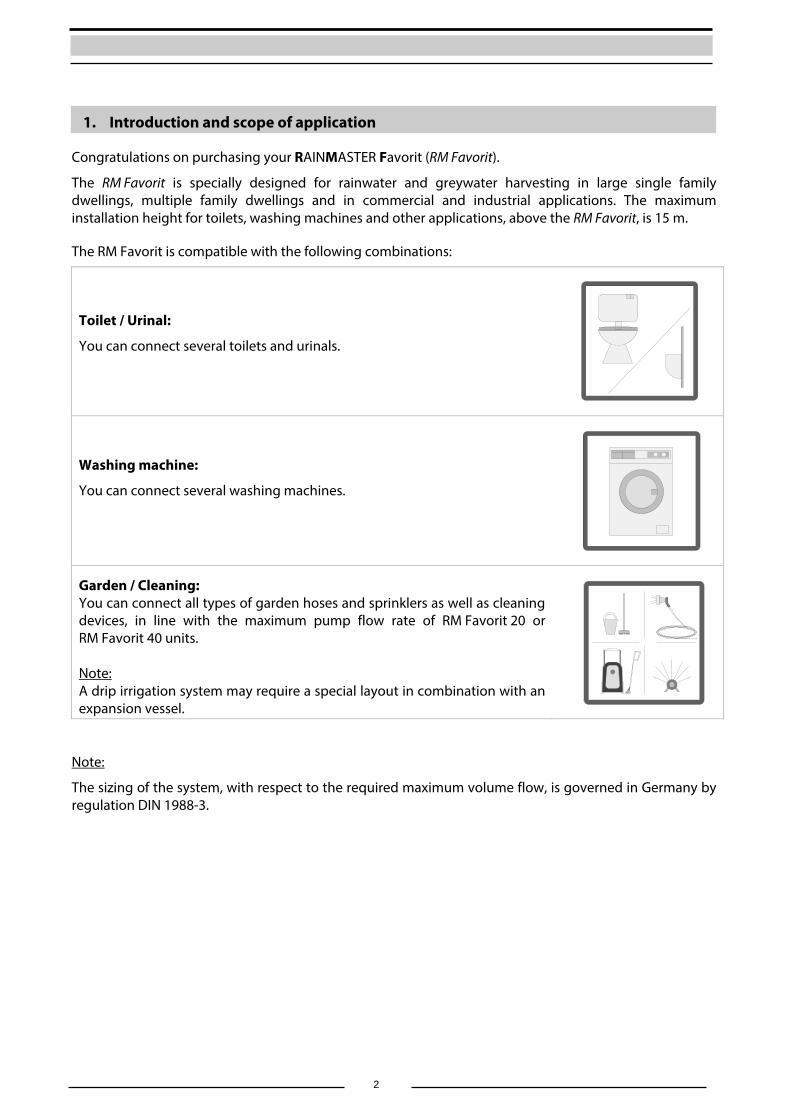
The RM Favorit is compatible with the following combinations:
Toilet / Urinal:
You can connect several toilets and urinals.
Washing machine:
You can connect several washing machines.
Garden / Cleaning: You can connect all types of garden hoses and sprinklers as well as cleaning devices, in line with the maximum pump flow rate of RM Favorit 20 or RM Favorit 40 units.
Note: A drip irrigation system may require a special layout in combination with an expansion vessel.
Note:
The sizing of the system, with respect to the required maximum volume flow, is governed in Germany by regulation DIN 1988-3.
3
1.1 Modes of operation Automatic mode In Automatic mode, the pump carries rainwater from the tank into the home and onto respective applications (e.g. toilets etc.). If the tank is empty, this is detected by the float switch in the tank, which instructs the electronic 3/2-way ball valve to change to the mains water mode. The rainwater intake line is then blocked and the required mains water is sourced from the built-in supplemental supply container inside the RM Favorit. After it rains, and the tank is topped-up with rainwater again, the float switch detects this and the electronic 3/2-way ball valve switches back to the rainwater intake setting.
Maintenance mode In Maintenance mode, the electronic ball valve stays permanently switched to mains water mode, and the house is continuously supplied with mains water from the supplemental supply container inside the RM Favorit.
In both working modes, the pump is switched on and off by means of the built-in pressure switch. The anti-dry running protection of the pump, and the stagnation protection of the supplemental water supply (the regular refreshing of water in the supplemental supply) are automatically controlled by the unit‘s built-in pump-controller.
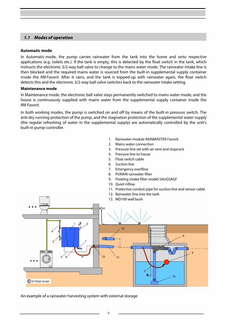
An example of a rainwater harvesting system with external storage
1. Rainwater module RAINMASTER Favorit 2. Mains water connection 3. Pressure line set with air vent and stopcock 4. Pressure line to house 5. Float switch cable 6. Suction line 7. Emergency overflow 8. PURAIN rainwater filter 9. Floating intake filter model SAUGSAGF 10. Quiet inflow 11. Protective conduit pipe for suction line and sensor cable 12. Rainwater line into the tank 13. MD100 wall bush
4
2. Safety instructions
This installation and operating manual is to be read carefully before installing the device. The instructions specified here are to be accurately followed, as failure to do so may lead to rejection of any warranty claim. This also applies to modifications to the RM Favorit. Moreover, any modification of the supplemental supply device or the electronic inside the unit will immediately nullify the warranty.
The user is responsible for compliance with safety and installation regulations. Only the original provided packaging is to be used for transportation of the equipment.
The emergency overflow of RM Favorit must always be connected.
Installation of the mains water line must only be carried out by an authorized installation company.
The RM Favorit internal housing for live electrical components shall only be opened by a qualified electrician.
The electrical circuit used to power this device must be protected by a 16A circuit breaker. Likewise, an ELCB (earth-leakage circuit breaker), with a maximum operating current of 30 mA, is to be used.
The operator is responsible for the compliance with safety regulations and for following these installation guidelines.

5
3. Scope of delivery
RAINMASTER Favorit unit
Wall mounting material and installation and user manual
Standard accessory A (Mains water connection):
Standard accessory B (Pressure line set):
Standard accessory C (Float switch):
6
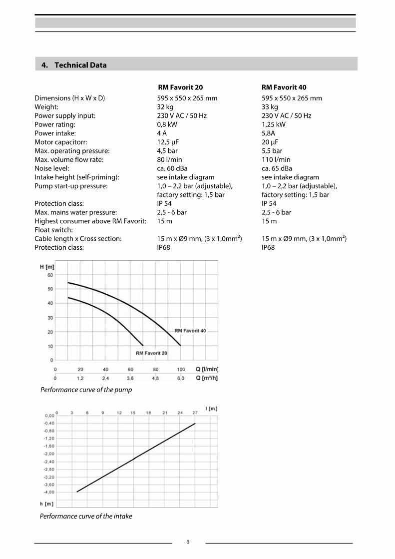
4. Technical Data
RM Favorit 20 RM Favorit 40 Dimensions (H x W x D) 595 x 550 x 265 mm 595 x 550 x 265 mm Weight: 32 kg 33 kg Power supply input: 230 V AC / 50 Hz 230 V AC / 50 Hz Power rating: 0,8 kW 1,25 kW Power intake: 4 A 5,8A Motor capacitorr: 12,5 µF 20 µF Max. operating pressure: 4,5 bar 5,5 bar Max. volume flow rate: 80 l/min 110 l/min Noise level: ca. 60 dBa ca. 65 dBa Intake height (self-priming): see intake diagram see intake diagram Pump start-up pressure: 1,0 – 2,2 bar (adjustable),
factory setting: 1,5 bar 1,0 – 2,2 bar (adjustable), factory setting: 1,5 bar
Protection class: IP 54 IP 54 Max. mains water pressure: 2,5 - 6 bar 2,5 - 6 bar Highest consumer above RM Favorit: 15 m 15 m Float switch: Cable length x Cross section:
15 m x Ø9 mm, (3 x 1,0mm²)
15 m x Ø9 mm, (3 x 1,0mm²)
Protection class: IP68 IP68
Performance curve of the pump
Performance curve of the intake
7
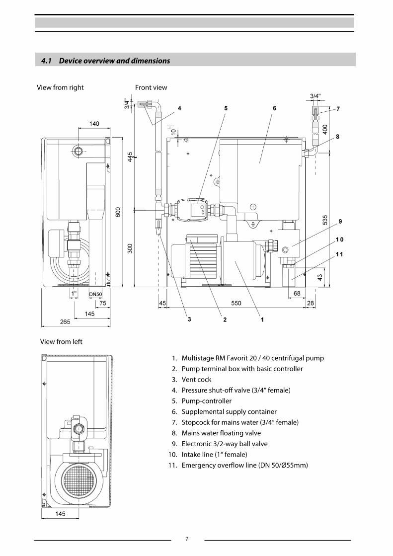
4.1 Device overview and dimensions
1. Multistage RM Favorit 20 / 40 centrifugal pump 2. Pump terminal box with basic controller 3. Vent cock 4. Pressure shut-off valve (3/4“ female) 5. Pump-controller 6. Supplemental supply container 7. Stopcock for mains water (3/4“ female) 8. Mains water floating valve 9. Electronic 3/2-way ball valve 10. Intake line (1“ female) 11. Emergency overflow line (DN 50/Ø55mm)
View from left
View from right Front view
8
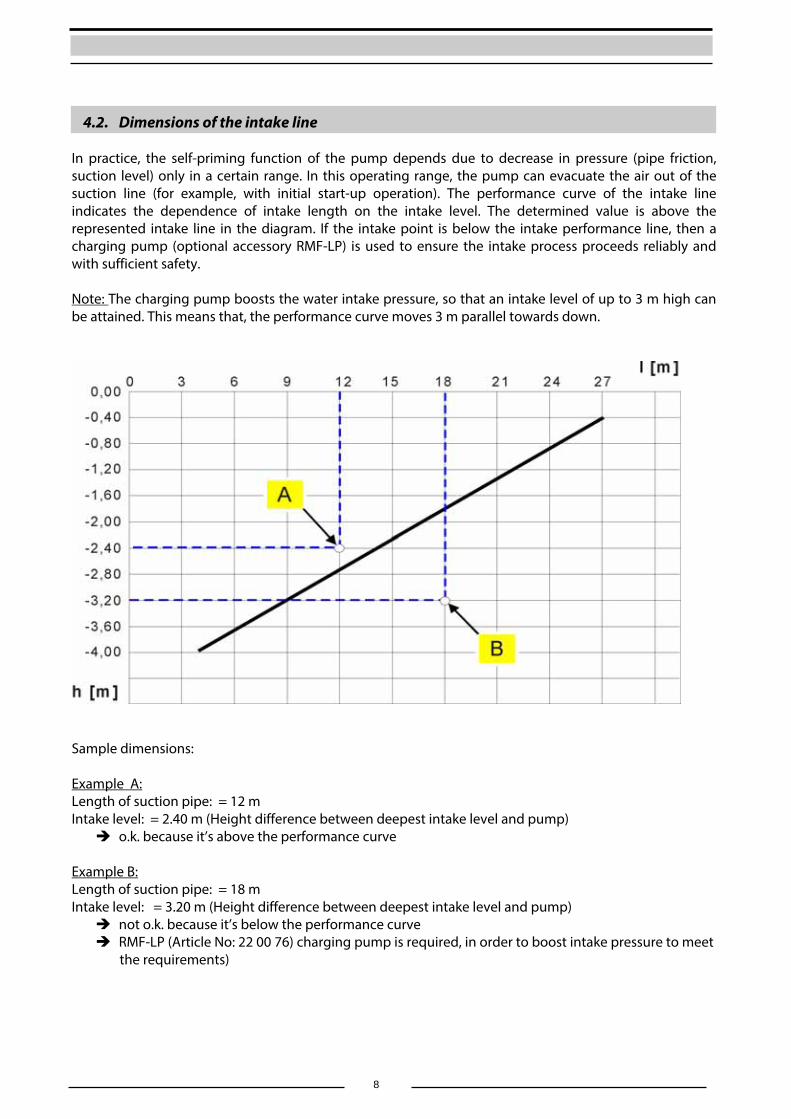
4.2. Dimensions of the intake line In practice, the self-priming function of the pump depends due to decrease in pressure (pipe friction, suction level) only in a certain range. In this operating range, the pump can evacuate the air out of the suction line (for example, with initial start-up operation). The performance curve of the intake line indicates the dependence of intake length on the intake level. The determined value is above the represented intake line in the diagram. If the intake point is below the intake performance line, then a charging pump (optional accessory RMF-LP) is used to ensure the intake process proceeds reliably and with sufficient safety. Note: The charging pump boosts the water intake pressure, so that an intake level of up to 3 m high can be attained. This means that, the performance curve moves 3 m parallel towards down.
Sample dimensions: Example A: Length of suction pipe: = 12 m Intake level: = 2.40 m (Height difference between deepest intake level and pump) o.k. because it’s above the performance curve
Example B: Length of suction pipe: = 18 m Intake level: = 3.20 m (Height difference between deepest intake level and pump) not o.k. because it’s below the performance curve RMF-LP (Article No: 22 00 76) charging pump is required, in order to boost intake pressure to meet
the requirements)
9
4.3 Standards, Directives, tests
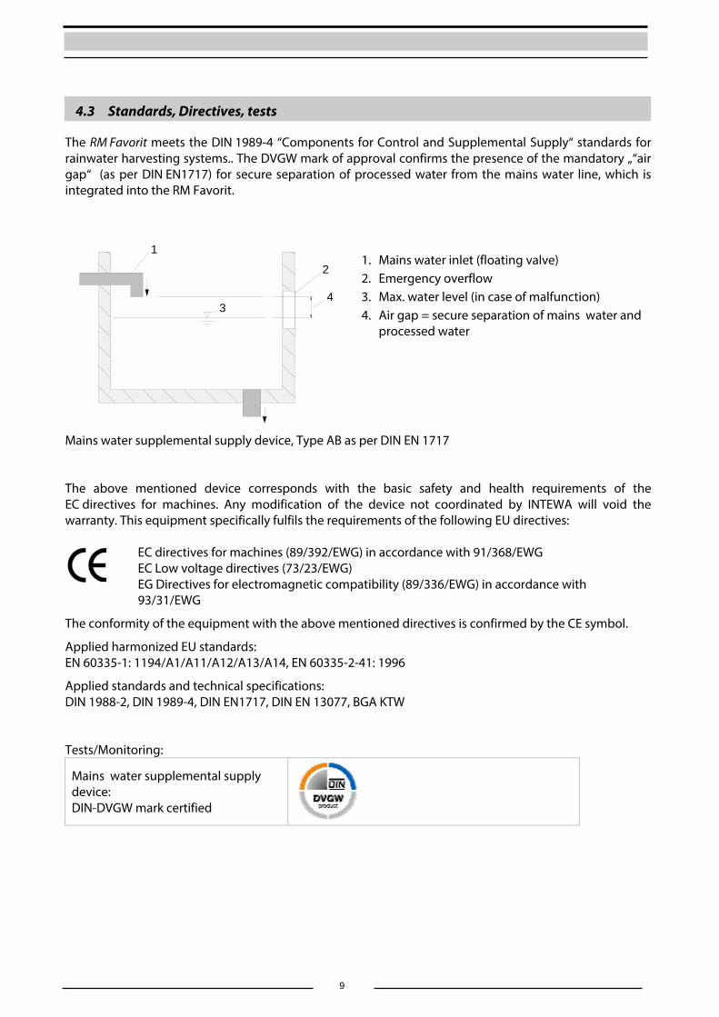
The RM Favorit meets the DIN 1989-4 “Components for Control and Supplemental Supply“ standards for rainwater harvesting systems.. The DVGW mark of approval confirms the presence of the mandatory „“air gap“ (as per DIN EN1717) for secure separation of processed water from the mains water line, which is integrated into the RM Favorit.
4
1
2
3
Mains water supplemental supply device, Type AB as per DIN EN 1717 The above mentioned device corresponds with the basic safety and health requirements of the EC directives for machines. Any modification of the device not coordinated by INTEWA will void the warranty. This equipment specifically fulfils the requirements of the following EU directives:
EC directives for machines (89/392/EWG) in accordance with 91/368/EWG EC Low voltage directives (73/23/EWG) EG Directives for electromagnetic compatibility (89/336/EWG) in accordance with 93/31/EWG
The conformity of the equipment with the above mentioned directives is confirmed by the CE symbol.
Applied harmonized EU standards: EN 60335-1: 1194/A1/A11/A12/A13/A14, EN 60335-2-41: 1996
Applied standards and technical specifications: DIN 1988-2, DIN 1989-4, DIN EN1717, DIN EN 13077, BGA KTW Tests/Monitoring:
Mains water supplemental supply device: DIN-DVGW mark certified
1. Mains water inlet (floating valve) 2. Emergency overflow 3. Max. water level (in case of malfunction) 4. Air gap = secure separation of mains water and
processed water
10
5. Overview of components The RM Favorit has a modular design. Each component can be separately changed.
5.1 Components of the pump-controller
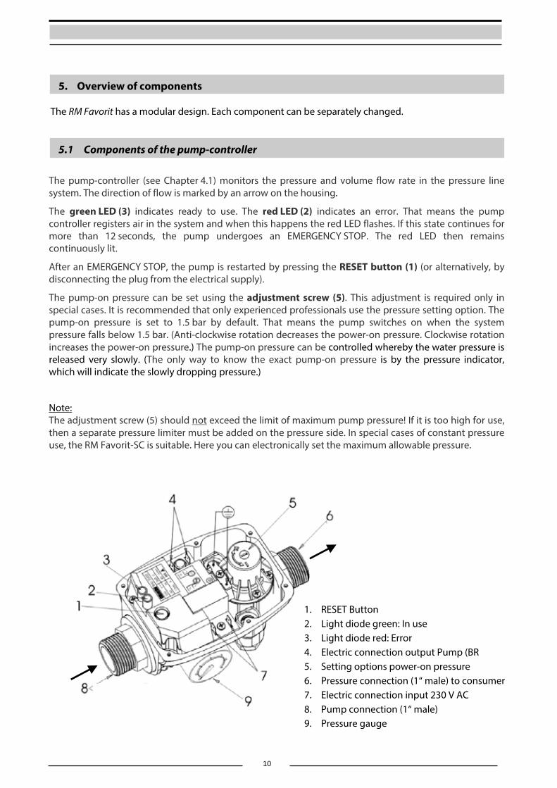
The pump-controller (see Chapter 4.1) monitors the pressure and volume flow rate in the pressure line system. The direction of flow is marked by an arrow on the housing.
The green LED (3) indicates ready to use. The red LED (2) indicates an error. That means the pump controller registers air in the system and when this happens the red LED flashes. If this state continues for more than 12 seconds, the pump undergoes an EMERGENCY STOP. The red LED then remains continuously lit.
After an EMERGENCY STOP, the pump is restarted by pressing the RESET button (1) (or alternatively, by disconnecting the plug from the electrical supply).
The pump-on pressure can be set using the adjustment screw (5). This adjustment is required only in special cases. It is recommended that only experienced professionals use the pressure setting option. The pump-on pressure is set to 1.5 bar by default. That means the pump switches on when the system pressure falls below 1.5 bar. (Anti-clockwise rotation decreases the power-on pressure. Clockwise rotation increases the power-on pressure.) The pump-on pressure can be controlled whereby the water pressure is released very slowly. (The only way to know the exact pump-on pressure is by the pressure indicator, which will indicate the slowly dropping pressure.)
Note: The adjustment screw (5) should not exceed the limit of maximum pump pressure! If it is too high for use, then a separate pressure limiter must be added on the pressure side. In special cases of constant pressure use, the RM Favorit-SC is suitable. Here you can electronically set the maximum allowable pressure.
1. RESET Button 2. Light diode green: In use 3. Light diode red: Error 4. Electric connection output Pump (BR 5. Setting options power-on pressure 6. Pressure connection (1“ male) to consumer 7. Electric connection input 230 V AC 8. Pump connection (1“ male) 9. Pressure gauge
11
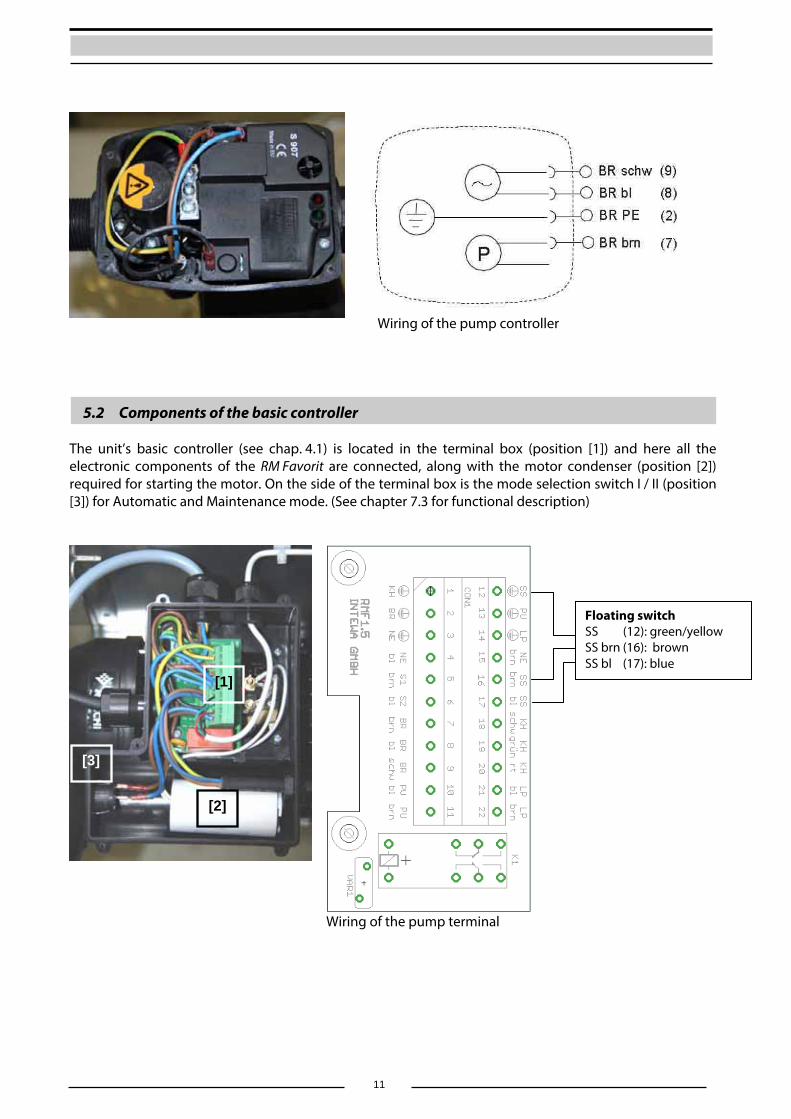
Wiring of the pump controller
5.2 Components of the basic controller The unit’s basic controller (see chap. 4.1) is located in the terminal box (position [1]) and here all the electronic components of the RM Favorit are connected, along with the motor condenser (position [2]) required for starting the motor. On the side of the terminal box is the mode selection switch I / II (position [3]) for Automatic and Maintenance mode. (See chapter 7.3 for functional description)
Wiring of the pump terminal
Floating switchSS (12): green/yellow SS brn (16): brown SS bl (17): blue
[1]
[2]
[3]

12
item Board inscription
Description of connection item Board inscription
Description of connection
1 2 3 4 5 6 7 8 9
10 11
KH PE BR PE NE PE NE bl S1 brn S1 bl BR brn BR bl BR schw PU bl PU brn
Protective conductor ball valveProtective conductor pump controller Protective conductor mains connection N- Mains connection 230V~, blue Selection Switch brown Selection Switch blue L1-Pump controller brown N-Pump controller blue Pump controller black N-Pump blue L1-Pump brown
1213 14 15 16 17 18 19 20 21 22
SS PEPU PE LP PE NE br SS brn SS bl KH schw KH grün KH rt LP bl LP brn
Protective conductor floating switchProtective conductor pump Protective conductor charge pump L1-Mains connection 230 V~, brown Floating switch brown Floating switch blue N-Ball valve black L1-Ball valve green L1-Ball valve red N-Charge pump blue L1-Charge pump brown
Overview of the cable connections The mode selection switch is wired with a flat pin plug.
Loosen the screws to change the condenser and take off the cable-end eyelet ring. Attention: Do not let the nuts fall down into the inner coil of the motor! Note: When connecting a new condenser the polarity is not important.
13
5.2 Components of the multistage pump
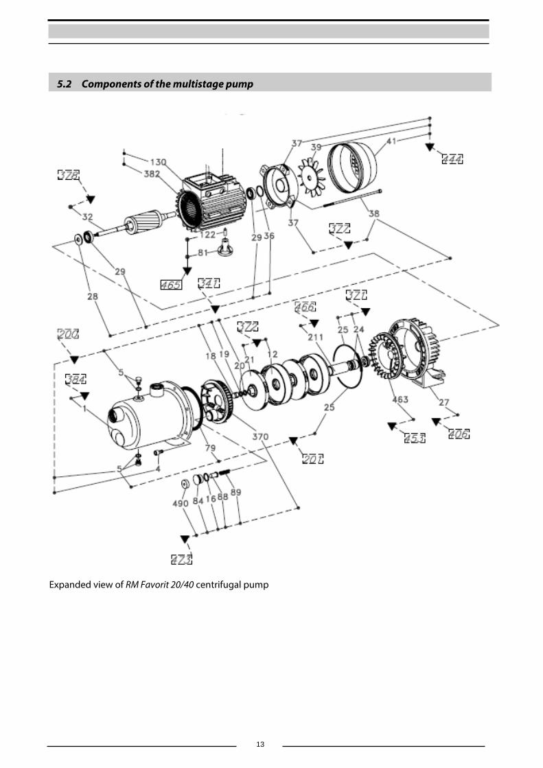
Expanded view of RM Favorit 20/40 centrifugal pump
14
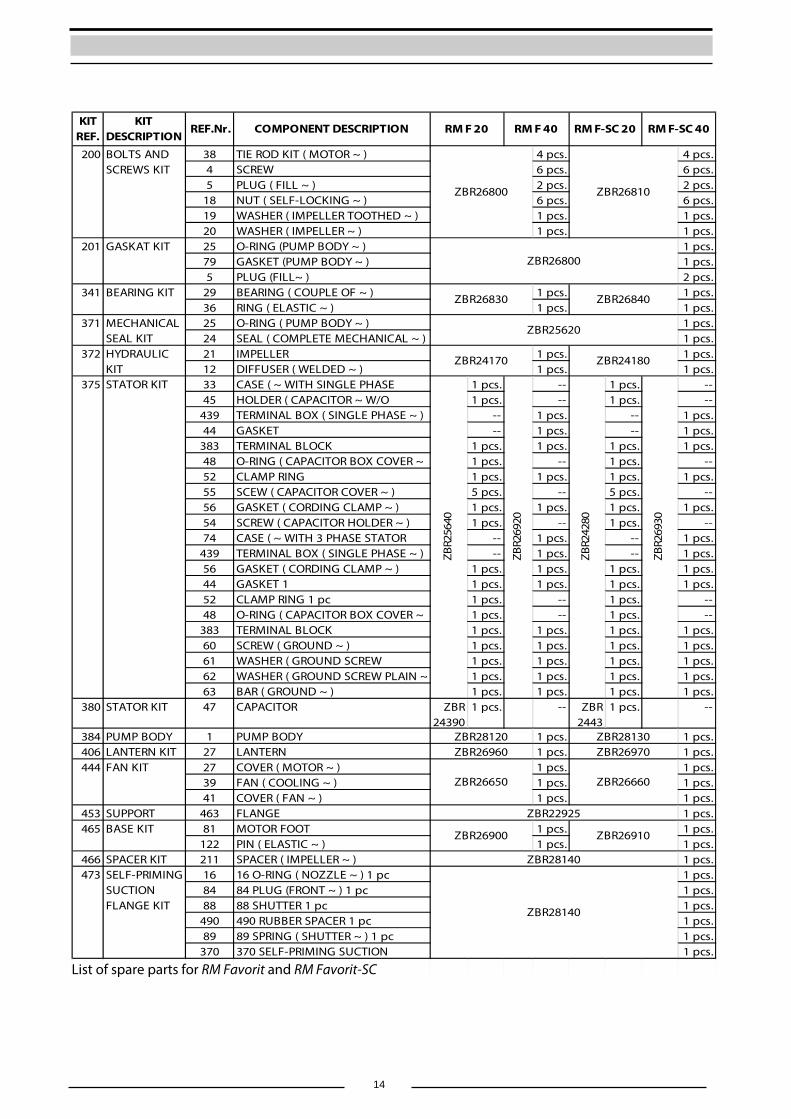
KIT REF.
KIT DESCRIPTION
REF.Nr. COMPONENT DESCRIPTION
38 TIE ROD KIT ( MOTOR ~ ) 4 pcs. 4 pcs.4 SCREW 6 pcs. 6 pcs.5 PLUG ( FILL ~ ) 2 pcs. 2 pcs.
18 NUT ( SELF-LOCKING ~ ) 6 pcs. 6 pcs.19 WASHER ( IMPELLER TOOTHED ~ ) 1 pcs. 1 pcs.20 WASHER ( IMPELLER ~ ) 1 pcs. 1 pcs.25 O-RING (PUMP BODY ~ ) 1 pcs.79 GASKET (PUMP BODY ~ ) 1 pcs.5 PLUG (FILL~ ) 2 pcs.
29 BEARING ( COUPLE OF ~ ) 1 pcs. 1 pcs.36 RING ( ELASTIC ~ ) 1 pcs. 1 pcs.25 O-RING ( PUMP BODY ~ ) 1 pcs.24 SEAL ( COMPLETE MECHANICAL ~ ) 1 pcs.21 IMPELLER 1 pcs. 1 pcs.12 DIFFUSER ( WELDED ~ ) 1 pcs. 1 pcs.33 CASE ( ~ WITH SINGLE PHASE 1 pcs. -- 1 pcs. --45 HOLDER ( CAPACITOR ~ W/O 1 pcs. -- 1 pcs. --
439 TERMINAL BOX ( SINGLE PHASE ~ ) -- 1 pcs. -- 1 pcs.44 GASKET -- 1 pcs. -- 1 pcs.
383 TERMINAL BLOCK 1 pcs. 1 pcs. 1 pcs. 1 pcs.48 O-RING ( CAPACITOR BOX COVER ~ 1 pcs. -- 1 pcs. --52 CLAMP RING 1 pcs. 1 pcs. 1 pcs. 1 pcs.55 SCEW ( CAPACITOR COVER ~ ) 5 pcs. -- 5 pcs. --56 GASKET ( CORDING CLAMP ~ ) 1 pcs. 1 pcs. 1 pcs. 1 pcs.54 SCREW ( CAPACITOR HOLDER ~ ) 1 pcs. -- 1 pcs. --74 CASE ( ~ WITH 3 PHASE STATOR -- 1 pcs. -- 1 pcs.
439 TERMINAL BOX ( SINGLE PHASE ~ ) -- 1 pcs. -- 1 pcs.56 GASKET ( CORDING CLAMP ~ ) 1 pcs. 1 pcs. 1 pcs. 1 pcs.44 GASKET 1 1 pcs. 1 pcs. 1 pcs. 1 pcs.52 CLAMP RING 1 pc 1 pcs. -- 1 pcs. --48 O-RING ( CAPACITOR BOX COVER ~ 1 pcs. -- 1 pcs. --
383 TERMINAL BLOCK 1 pcs. 1 pcs. 1 pcs. 1 pcs.60 SCREW ( GROUND ~ ) 1 pcs. 1 pcs. 1 pcs. 1 pcs.61 WASHER ( GROUND SCREW 1 pcs. 1 pcs. 1 pcs. 1 pcs.62 WASHER ( GROUND SCREW PLAIN ~ 1 pcs. 1 pcs. 1 pcs. 1 pcs.63 BAR ( GROUND ~ ) 1 pcs. 1 pcs. 1 pcs. 1 pcs.
380 STATOR KIT 47 CAPACITOR ZBR24390
1 pcs. -- ZBR2443
1 pcs. --
384 PUMP BODY 1 PUMP BODY 1 pcs. 1 pcs.406 LANTERN KIT 27 LANTERN 1 pcs. 1 pcs.
27 COVER ( MOTOR ~ ) 1 pcs. 1 pcs.39 FAN ( COOLING ~ ) 1 pcs. 1 pcs.41 COVER ( FAN ~ ) 1 pcs. 1 pcs.
453 SUPPORT 463 FLANGE 1 pcs.81 MOTOR FOOT 1 pcs. 1 pcs.
122 PIN ( ELASTIC ~ ) 1 pcs. 1 pcs.466 SPACER KIT 211 SPACER ( IMPELLER ~ ) 1 pcs.
16 16 O-RING ( NOZZLE ~ ) 1 pc 1 pcs.84 84 PLUG (FRONT ~ ) 1 pc 1 pcs.88 88 SHUTTER 1 pc 1 pcs.
490 490 RUBBER SPACER 1 pc 1 pcs.89 89 SPRING ( SHUTTER ~ ) 1 pc 1 pcs.
370 370 SELF-PRIMING SUCTION 1 pcs.
RM F 20 RM F 40 RM F-SC 20 RM F-SC 40
200 BOLTS AND SCREWS KIT
ZBR26800 ZBR26810
201 GASKAT KITZBR26800
341 BEARING KIT ZBR26830 ZBR26840
ZBR2
6930
371 MECHANICAL SEAL KIT
ZBR25620
372 HYDRAULIC KIT
ZBR24170 ZBR24180
375 STATOR KIT
ZBR2
5640
ZBR2
6920
ZBR2
4280
ZBR28120 ZBR28130ZBR26960 ZBR26970
444 FAN KITZBR26650 ZBR26660
473 SELF-PRIMING SUCTIONFLANGE KIT ZBR28140
ZBR22925465 BASE KIT ZBR26900 ZBR26910
ZBR28140
List of spare parts for RM Favorit and RM Favorit-SC
15
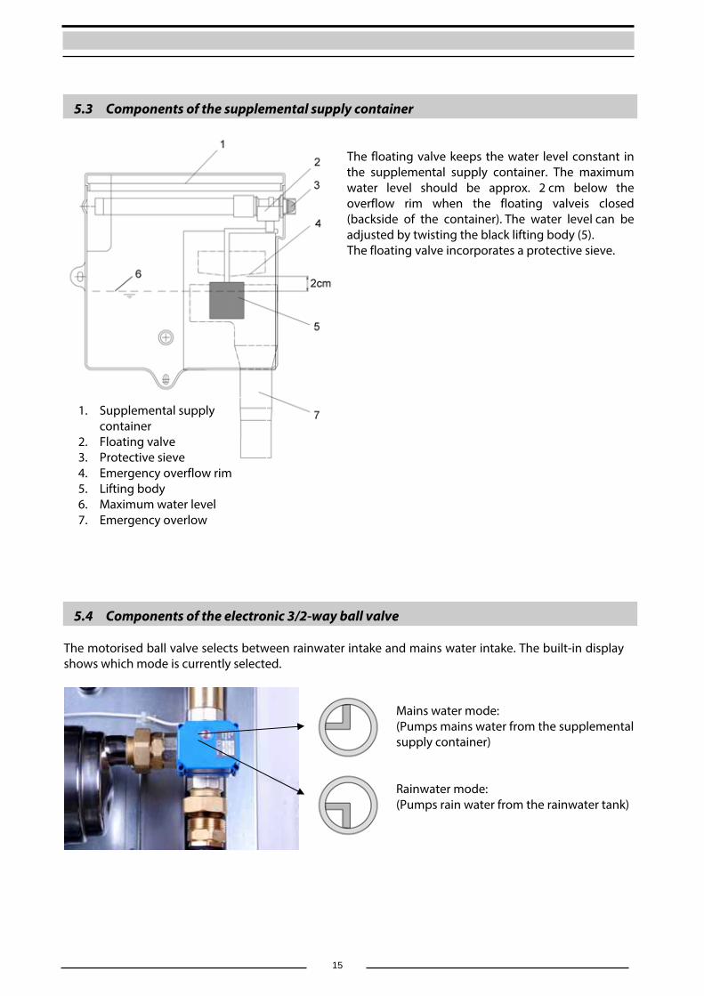
5.3 Components of the supplemental supply container
The floating valve keeps the water level constant in the supplemental supply container. The maximum water level should be approx. 2 cm below the overflow rim when the floating valveis closed (backside of the container). The water level can be adjusted by twisting the black lifting body (5). The floating valve incorporates a protective sieve.
5.4 Components of the electronic 3/2-way ball valve The motorised ball valve selects between rainwater intake and mains water intake. The built-in display shows which mode is currently selected.
1. Supplemental supply container
2. Floating valve 3. Protective sieve 4. Emergency overflow rim 5. Lifting body 6. Maximum water level 7. Emergency overlow
Mains water mode: (Pumps mains water from the supplemental supply container) Rainwater mode: (Pumps rain water from the rainwater tank)
16
6. Installation instructions
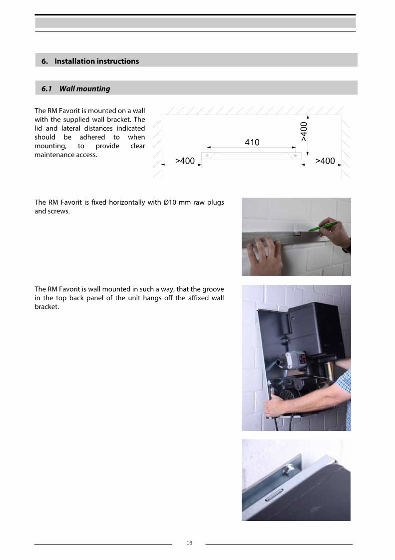
6.1 Wall mounting
The RM Favorit is mounted on a wall with the supplied wall bracket. The lid and lateral distances indicated should be adhered to when mounting, to provide clear maintenance access.
The RM Favorit is fixed horizontally with Ø10 mm raw plugs and screws.
The RM Favorit is wall mounted in such a way, that the groove in the top back panel of the unit hangs off the affixed wall bracket.

17
The provided rubber clamping device is to be fit on the back side of the unit in the lower corners. The unevenness of the wall can be balanced by various screwing depths.
6.2 Connection to the mains water line The connection to the mains water supply is done with the provided flexible hose and stopcock. Screw the gland screw into the container connection and carefully tighten with a fixed spanner. Note: The flexible hose must not be overtightened as this may interfere with the internal float valve, on the opposite side of the connection. All provided flexible hoses have gland screws with flat washers. The rubber washers must be present. Additional sealing material must not be used on gland nuts! Screw the gland screw on the other end of the flexible pipe into the stopcock mounted on the mains water line.
18
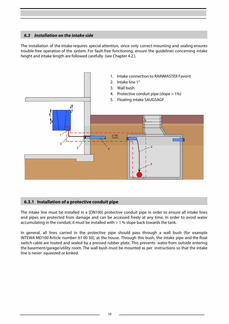
6.3 Installation on the intake side The installation of the intake requires special attention, since only correct mounting and sealing ensures trouble-free operation of the system. For fault-free functioning, ensure the guidelines concerning intake height and intake length are followed carefully (see Chapter 4.2.).
6.3.1 Installation of a protective conduit pipe The intake line must be installed in a (DN100) protective conduit pipe in order to ensure all intake lines and pipes are protected from damage and can be accessed freely at any time. In order to avoid water accumulating in the conduit, it must be installed with > 1 % slope back towards the tank. In general, all lines carried in the protective pipe should pass through a wall bush (for example INTEWA MD100 Article number: 61 00 50), at the house. Through this bush, the intake pipe and the float switch cable are routed and sealed by a pressed rubber plate. This prevents water from outside entering the basement/garage/utility room. The wall bush must be mounted as per instructions so that the intake line is never squeezed or kinked.
1. Intake connection to RAINMASTER Favorit 2. Intake line 1“ 3. Wall bush 4. Protective conduit pipe (slope > 1%) 5. Floating intake SAUGSAGF
19
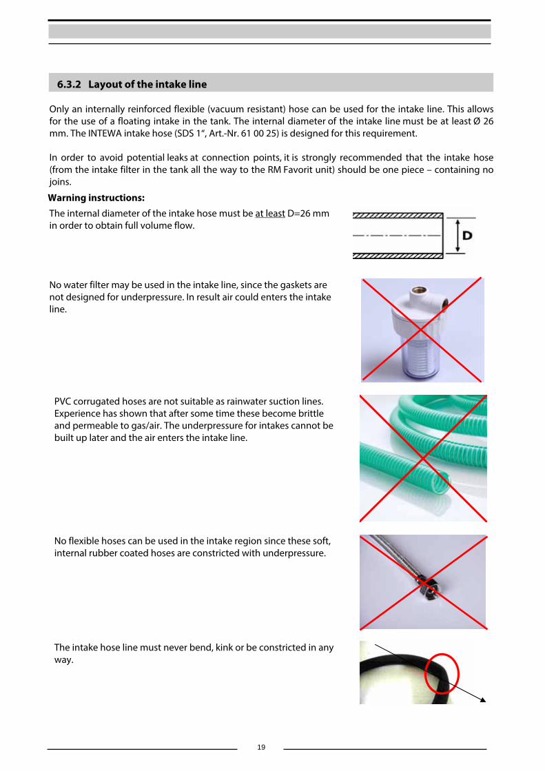
6.3.2 Layout of the intake line Only an internally reinforced flexible (vacuum resistant) hose can be used for the intake line. This allows for the use of a floating intake in the tank. The internal diameter of the intake line must be at least Ø 26 mm. The INTEWA intake hose (SDS 1“, Art.-Nr. 61 00 25) is designed for this requirement. In order to avoid potential leaks at connection points, it is strongly recommended that the intake hose (from the intake filter in the tank all the way to the RM Favorit unit) should be one piece – containing no joins.
Warning instructions:
The internal diameter of the intake hose must be at least D=26 mm in order to obtain full volume flow.
No water filter may be used in the intake line, since the gaskets are not designed for underpressure. In result air could enters the intake line.
PVC corrugated hoses are not suitable as rainwater suction lines. Experience has shown that after some time these become brittle and permeable to gas/air. The underpressure for intakes cannot be built up later and the air enters the intake line.
No flexible hoses can be used in the intake region since these soft, internal rubber coated hoses are constricted with underpressure.
The intake hose line must never bend, kink or be constricted in any way.
20
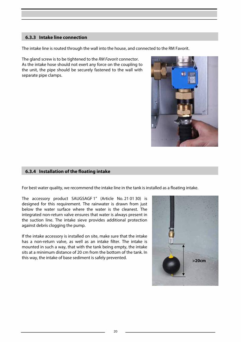
6.3.3 Intake line connection The intake line is routed through the wall into the house, and connected to the RM Favorit. The gland screw is to be tightened to the RM Favorit connector. As the intake hose should not exert any force on the coupling to the unit, the pipe should be securely fastened to the wall with separate pipe clamps.
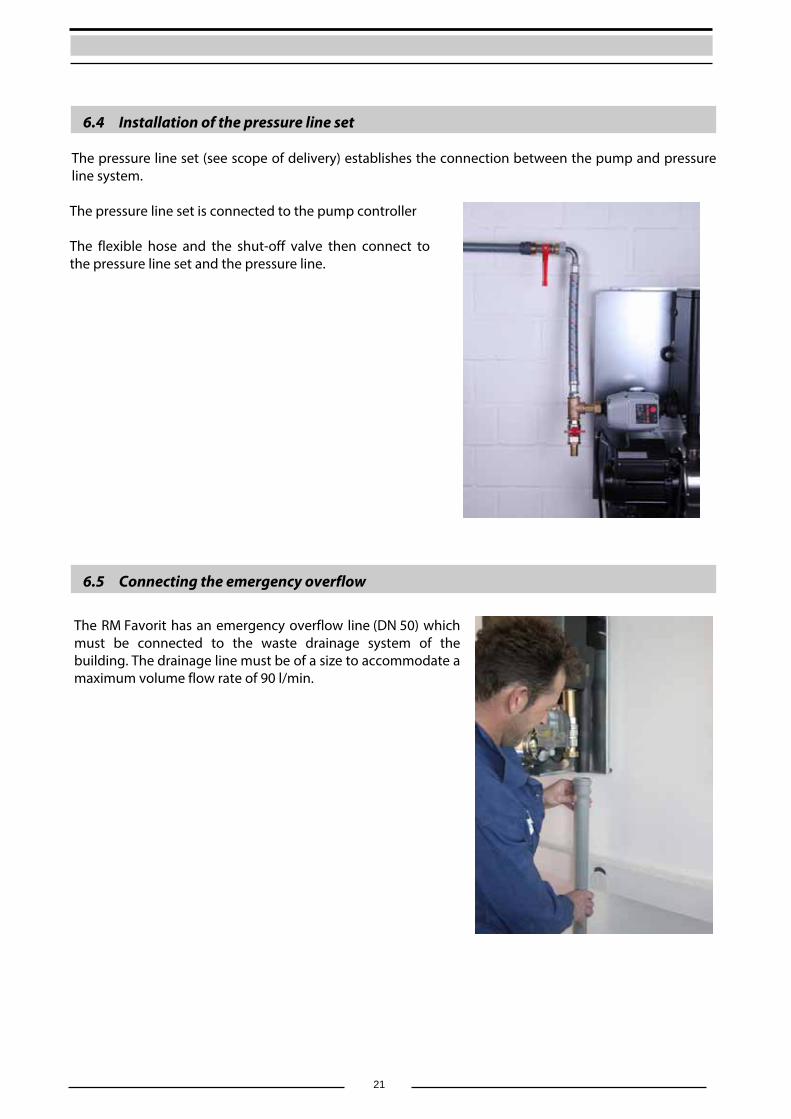
6.3.4 Installation of the floating intake For best water quality, we recommend the intake line in the tank is installed as a floating intake. The accessory product SAUGSAGF 1” (Article No. 21 01 30) is designed for this requirement. The rainwater is drawn from just below the water surface where the water is the cleanest. The integrated non-return valve ensures that water is always present in the suction line. The intake sieve provides additional protection against debris clogging the pump. If the intake accessory is installed on site, make sure that the intake has a non-return valve, as well as an intake filter. The intake is mounted in such a way, that with the tank being empty, the intake sits at a minimum distance of 20 cm from the bottom of the tank. In this way, the intake of base sediment is safely prevented.
>20cm
21
6.4 Installation of the pressure line set The pressure line set (see scope of delivery) establishes the connection between the pump and pressure line system. The pressure line set is connected to the pump controller The flexible hose and the shut-off valve then connect to the pressure line set and the pressure line.
6.5 Connecting the emergency overflow
The RM Favorit has an emergency overflow line (DN 50) which must be connected to the waste drainage system of the building. The drainage line must be of a size to accommodate a maximum volume flow rate of 90 l/min.
22
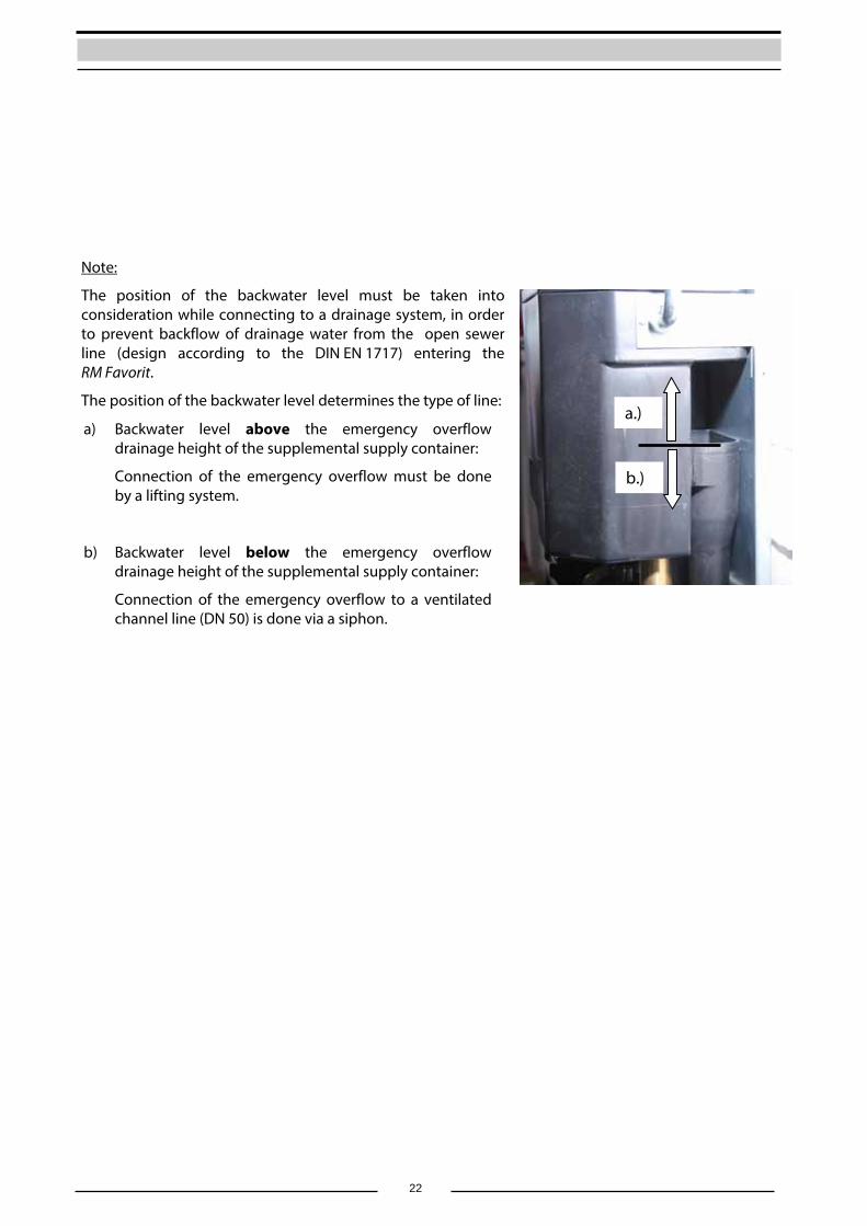
Note:
The position of the backwater level must be taken into consideration while connecting to a drainage system, in order to prevent backflow of drainage water from the open sewer line (design according to the DIN EN 1717) entering the RM Favorit.
The position of the backwater level determines the type of line:
a) Backwater level above the emergency overflow drainage height of the supplemental supply container:
Connection of the emergency overflow must be done by a lifting system.
b) Backwater level below the emergency overflow drainage height of the supplemental supply container:
Connection of the emergency overflow to a ventilated channel line (DN 50) is done via a siphon.
a.)
b.)
23
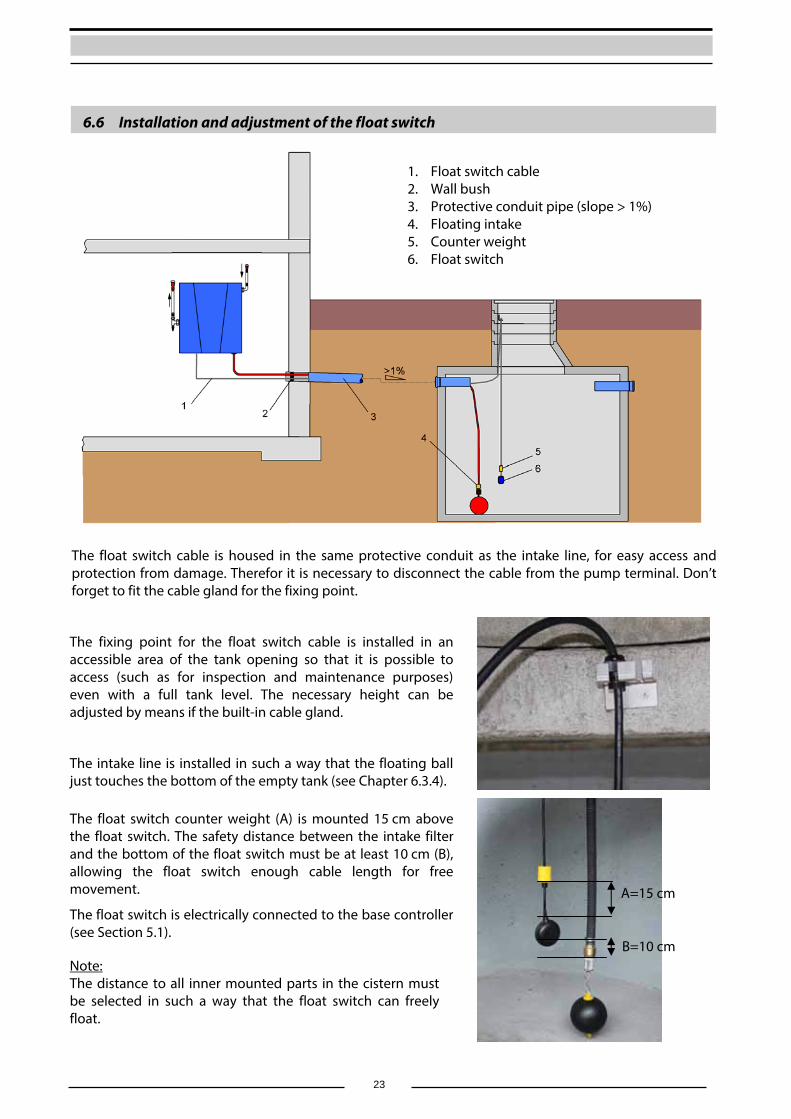
6.6 Installation and adjustment of the float switch
The float switch cable is housed in the same protective conduit as the intake line, for easy access and protection from damage. Therefor it is necessary to disconnect the cable from the pump terminal. Don’t forget to fit the cable gland for the fixing point.
The fixing point for the float switch cable is installed in an accessible area of the tank opening so that it is possible to access (such as for inspection and maintenance purposes) even with a full tank level. The necessary height can be adjusted by means if the built-in cable gland.
The intake line is installed in such a way that the floating ball just touches the bottom of the empty tank (see Chapter 6.3.4).
The float switch counter weight (A) is mounted 15 cm above the float switch. The safety distance between the intake filter and the bottom of the float switch must be at least 10 cm (B), allowing the float switch enough cable length for free movement.
The float switch is electrically connected to the base controller (see Section 5.1).
Note: The distance to all inner mounted parts in the cistern must be selected in such a way that the float switch can freely float.
1. Float switch cable 2. Wall bush 3. Protective conduit pipe (slope > 1%) 4. Floating intake 5. Counter weight 6. Float switch
A=15 cm
B=10 cm
24
7. Start up and use
7.1 Start-up in mains water mode
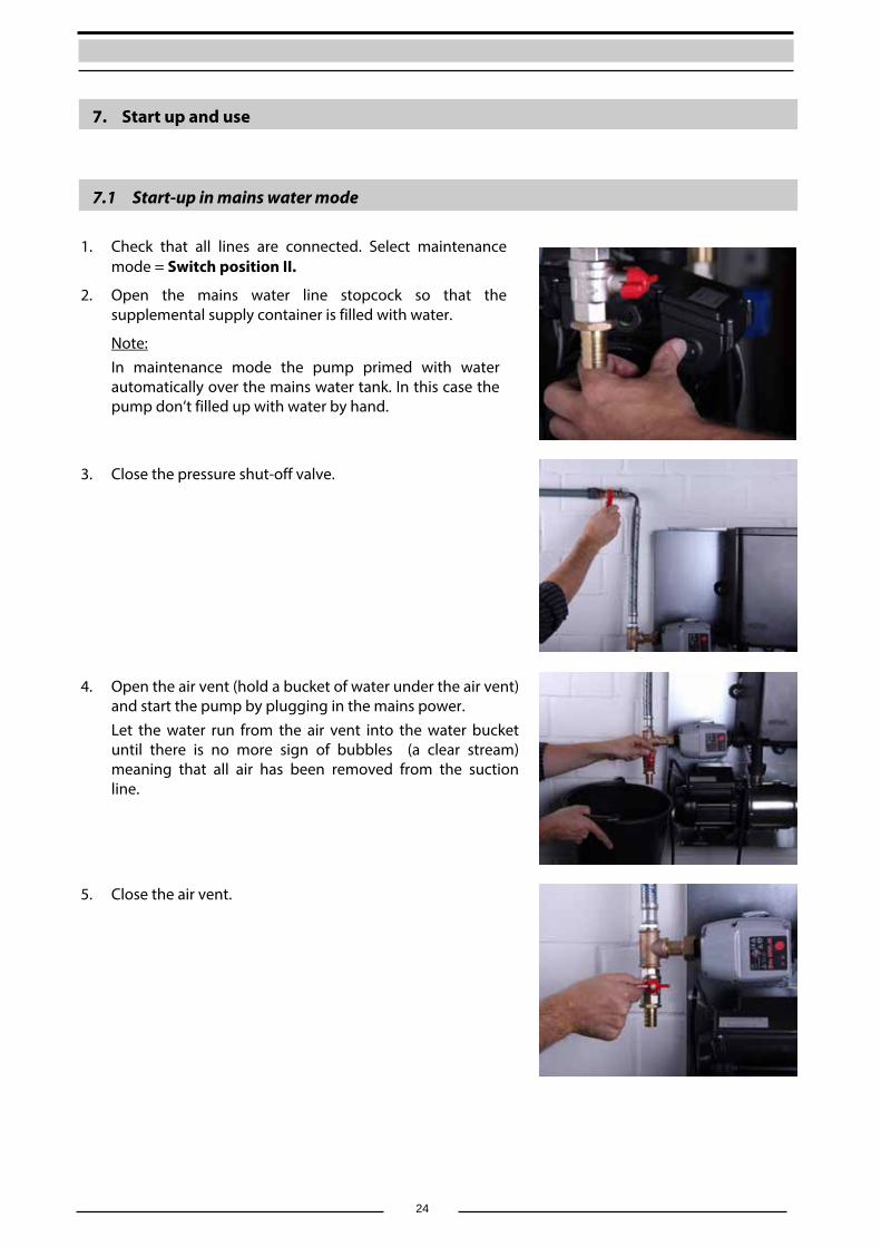
1. Check that all lines are connected. Select maintenance mode = Switch position II.
2. Open the mains water line stopcock so that the supplemental supply container is filled with water.
Note: In maintenance mode the pump primed with water automatically over the mains water tank. In this case the pump don’t filled up with water by hand.
3. Close the pressure shut-off valve.
4. Open the air vent (hold a bucket of water under the air vent)
and start the pump by plugging in the mains power. Let the water run from the air vent into the water bucket until there is no more sign of bubbles (a clear stream) meaning that all air has been removed from the suction line.
5. Close the air vent.
25
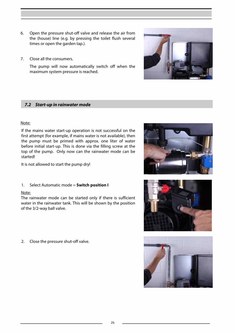
6. Open the pressure shut-off valve and release the air from the (house) line (e.g. by pressing the toilet flush several times or open the garden tap.).
7. Close all the consumers.
The pump will now automatically switch off when the maximum system pressure is reached.
7.2 Start-up in rainwater mode
Note:
If the mains water start-up operation is not successful on the first attempt (for example, if mains water is not available), then the pump must be primed with approx. one liter of water before initial start-up. This is done via the filling screw at the top of the pump. Only now can the rainwater mode can be started!
It is not allowed to start the pump dry!
1. Select Automatic mode = Switch position I
Note: The rainwater mode can be started only if there is sufficient water in the rainwater tank. This will be shown by the position of the 3/2-way ball valve.
2. Close the pressure shut-off valve.
26
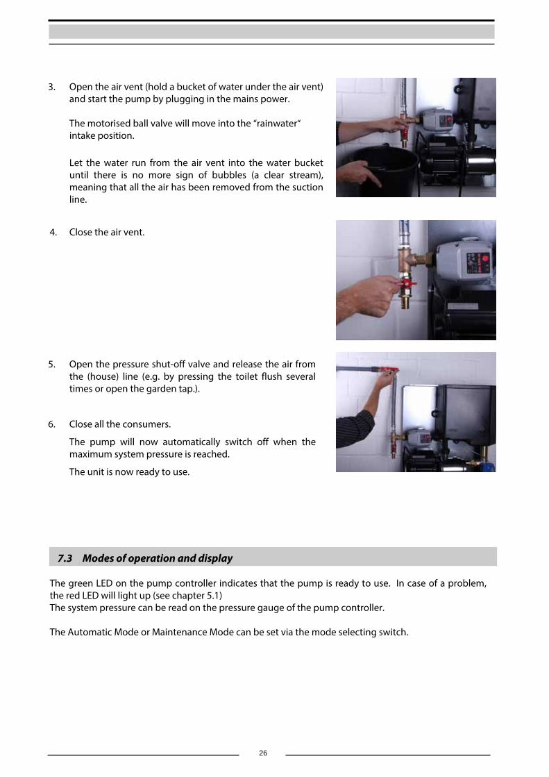
3. Open the air vent (hold a bucket of water under the air vent) and start the pump by plugging in the mains power.
The motorised ball valve will move into the “rainwater“ intake position.
Let the water run from the air vent into the water bucket until there is no more sign of bubbles (a clear stream), meaning that all the air has been removed from the suction line.
4. Close the air vent.
5. Open the pressure shut-off valve and release the air from the (house) line (e.g. by pressing the toilet flush several times or open the garden tap.).
6. Close all the consumers.
The pump will now automatically switch off when the maximum system pressure is reached.
The unit is now ready to use.
7.3 Modes of operation and display The green LED on the pump controller indicates that the pump is ready to use. In case of a problem, the red LED will light up (see chapter 5.1) The system pressure can be read on the pressure gauge of the pump controller. The Automatic Mode or Maintenance Mode can be set via the mode selecting switch.
27
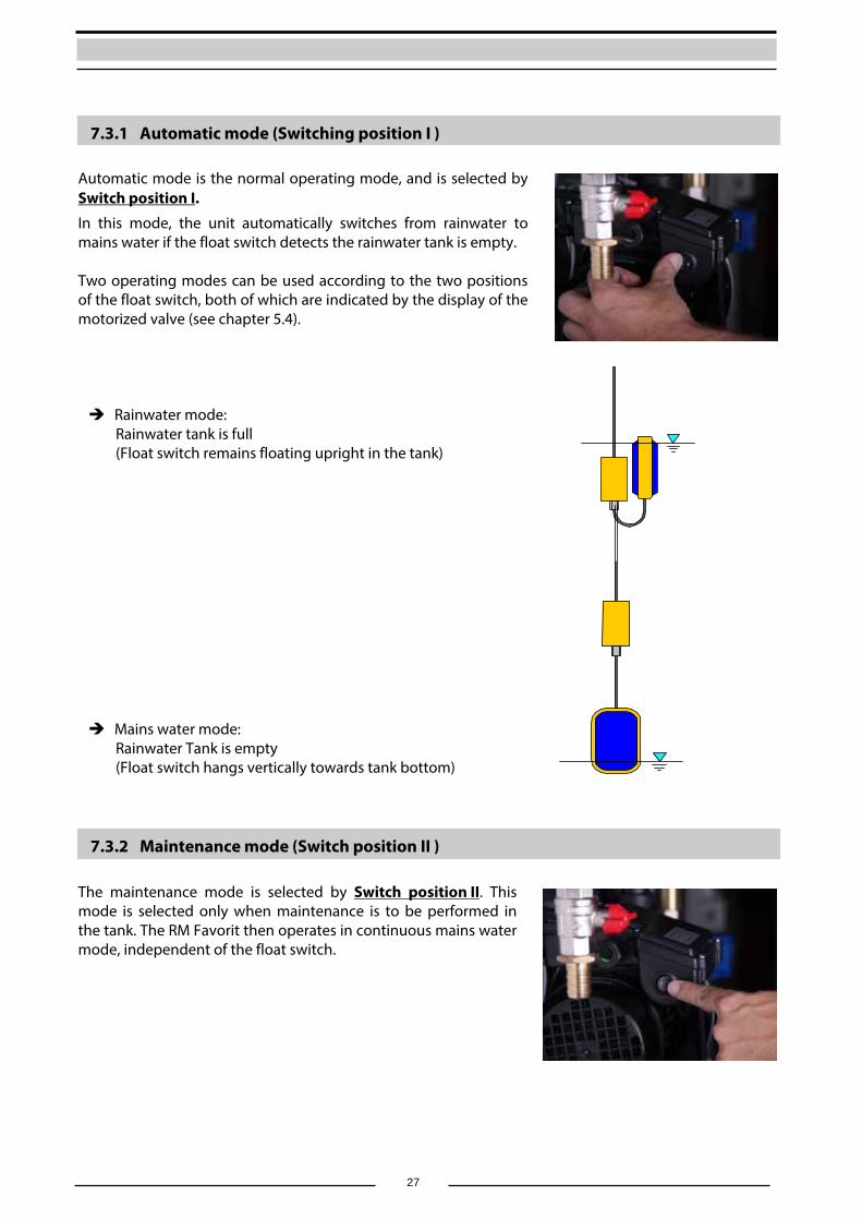
7.3.1 Automatic mode (Switching position I )
Automatic mode is the normal operating mode, and is selected by Switch position I.
In this mode, the unit automatically switches from rainwater to mains water if the float switch detects the rainwater tank is empty. Two operating modes can be used according to the two positions of the float switch, both of which are indicated by the display of the motorized valve (see chapter 5.4). Rainwater mode:
Rainwater tank is full (Float switch remains floating upright in the tank)
Mains water mode: Rainwater Tank is empty (Float switch hangs vertically towards tank bottom)
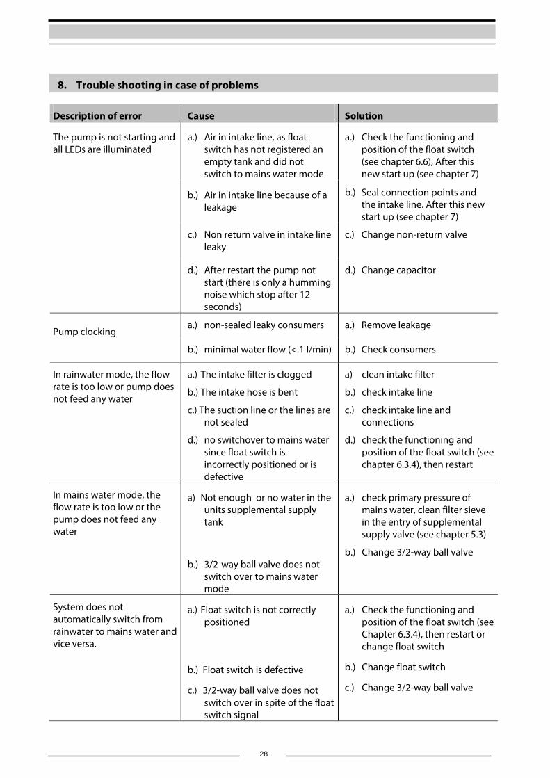
7.3.2 Maintenance mode (Switch position II )
The maintenance mode is selected by Switch position II. This mode is selected only when maintenance is to be performed in the tank. The RM Favorit then operates in continuous mains water mode, independent of the float switch.
28
8. Trouble shooting in case of problems
Description of error Cause Solution
The pump is not starting and all LEDs are illuminated
a.) Air in intake line, as float switch has not registered an empty tank and did not switch to mains water mode
a.) Check the functioning and position of the float switch (see chapter 6.6), After this new start up (see chapter 7)
b.) Air in intake line because of a leakage
b.) Seal connection points and the intake line. After this new start up (see chapter 7)
c.) Non return valve in intake line leaky
c.) Change non-return valve
d.) After restart the pump not start (there is only a humming noise which stop after 12 seconds)
d.) Change capacitor
Pump clocking
a.) non-sealed leaky consumers a.) Remove leakage
b.) minimal water flow (< 1 l/min) b.) Check consumers
In rainwater mode, the flow rate is too low or pump does not feed any water
a.) The intake filter is clogged
b.) The intake hose is bent
c.) The suction line or the lines are not sealed
d.) no switchover to mains water since float switch is incorrectly positioned or is defective
a) clean intake filter
b.) check intake line
c.) check intake line and connections
d.) check the functioning and position of the float switch (see chapter 6.3.4), then restart
In mains water mode, the flow rate is too low or the pump does not feed any water
a) Not enough or no water in the units supplemental supply tank
b.) 3/2-way ball valve does not switch over to mains water mode
a.) check primary pressure of mains water, clean filter sieve in the entry of supplemental supply valve (see chapter 5.3)
b.) Change 3/2-way ball valve
System does not automatically switch from rainwater to mains water and vice versa.
a.) Float switch is not correctly positioned
b.) Float switch is defective
c.) 3/2-way ball valve does not switch over in spite of the float switch signal
a.) Check the functioning and position of the float switch (see Chapter 6.3.4), then restart or change float switch
b.) Change float switch
c.) Change 3/2-way ball valve
29
9. Maintenance
The RM Favorit operates without requiring any maintenance. However, every six months the intake filter should be cleaned in the rainwater tank.
10. Spare parts
Description Figure no.
(see chapter 4.1) Order name
Multistage rotary pump for RMF 20 [1] RMF-P20 Multistage rotary pump for RMF 40 [1] RMF-P40 Basic-controller [2] RMF-BPLPump-controller Brio [5] RMF-PST BRIO Supplemental supply container [6] RMF-B Floating valve for supplemental supply container [8] RMF-NSP 3/2-way ball valve [9] RMF-KH Float switch, 15m RMF-SCHW15 Spare part for centrifugal pump see chapter 5.2
11. Optional Accessories
RMD-24, Art.-No. 22 00 92 The RAINMASTER D 24 is a fill level unit for water tanks up to 3 m water depth. It can be installed everywhere in the house and is a perfect complement for the RAINMASTER Favorit rainwater unit.
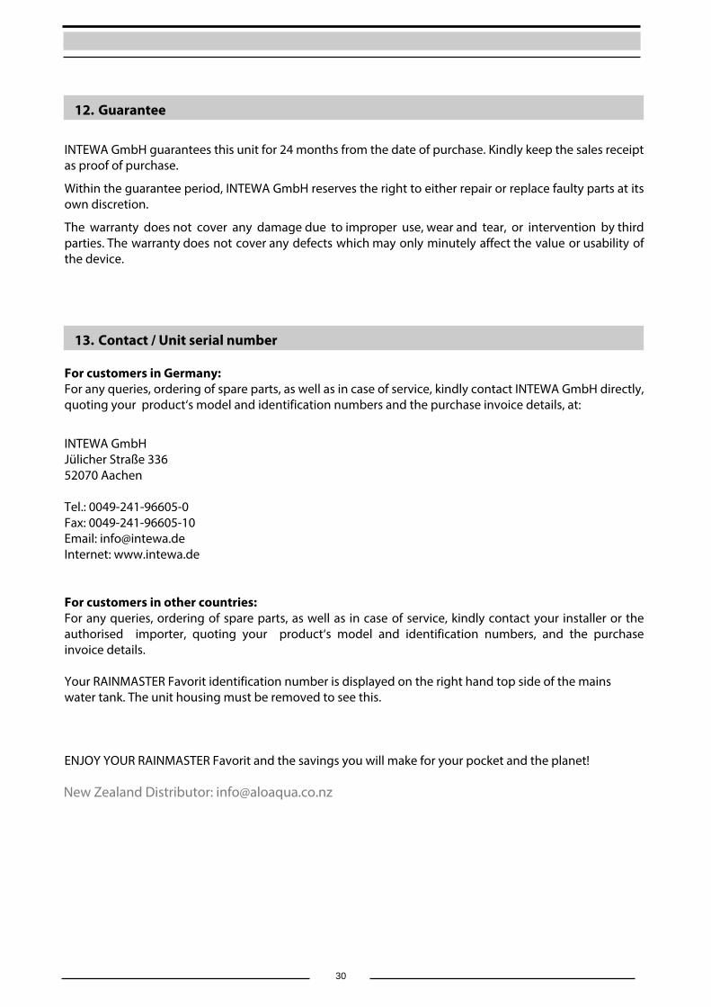
RMF-LP, Art.-No. 22 00 76
Charging pump for boosting the water intake line pressure from higher intake depths or longer intake lengths. The electric connection is effected by the basis control of the RM Favorit.
30
12. Guarantee
INTEWA GmbH guarantees this unit for 24 months from the date of purchase. Kindly keep the sales receipt as proof of purchase.
Within the guarantee period, INTEWA GmbH reserves the right to either repair or replace faulty parts at its own discretion.
The warranty does not cover any damage due to improper use, wear and tear, or intervention by third parties. The warranty does not cover any defects which may only minutely affect the value or usability of the device.
13. Contact / Unit serial number
For customers in Germany: For any queries, ordering of spare parts, as well as in case of service, kindly contact INTEWA GmbH directly, quoting your product‘s model and identification numbers and the purchase invoice details, at:
INTEWA GmbH Jülicher Straße 336 52070 Aachen
Tel.: 0049-241-96605-0 Fax: 0049-241-96605-10 Email: [email protected] Internet: www.intewa.de
For customers in other countries: For any queries, ordering of spare parts, as well as in case of service, kindly contact your installer or the authorised importer, quoting your product‘s model and identification numbers, and the purchase invoice details.
Your RAINMASTER Favorit identification number is displayed on the right hand top side of the mains water tank. The unit housing must be removed to see this.
ENJOY YOUR RAINMASTER Favorit and the savings you will make for your pocket and the planet!
New Zealand Distributor: [email protected]

31
© INTEWA GmbH Version: 2.8c Subject to technical changes.
Related Documents