RBDG-MAN-013-0105 The sole responsibility of this publication lies with the author. The European Union is not responsible for any use that may be made of the information contained therein. Design guidelines Railway Alignment 07-06-2021

Welcome message from author
This document is posted to help you gain knowledge. Please leave a comment to let me know what you think about it! Share it to your friends and learn new things together.
Transcript
RBDG-MAN-013-0105
The sole responsibility of this publication lies with the author. The European Union is not responsible for any use that may be made of the information contained therein.
Design guidelines
Railway Alignment
07-06-2021
Design guidelines Railway Alignment
RBDG-MAN-013-0105 page 2/21
Table of Contents
Standards and requirement classification ..................................................................................................................................... 4
General rules related to geometry ................................................................................................................................................... 5
Design of railway alignment in correspondence with maximum operational speed .......................................................... 5
Railway alignment in urban areas in proximity to international passenger stations ............................................................ 5
2.1. Shunting limits ............................................................................................................................................................................. 6
Shunting limits when both tracks are straight .................................................................................................................. 7
Shunting limits when one or both tracks are curved ..................................................................................................... 7
Part 1 - Mixed Traffic Line ................................................................................................................................................................................ 9
General plan characteristics ................................................................................................................................................................ 9
3.1. Cant (D) .......................................................................................................................................................................................... 9
3.2. Cant excess (E) ............................................................................................................................................................................. 9
3.3. Cant deficiency (I) ....................................................................................................................................................................... 9
3.4. Minimum radius of horizontal curve (R) ............................................................................................................................ 10
3.5. Station characteristics ............................................................................................................................................................. 10
3.6. Cant calculation (D) .................................................................................................................................................................. 11
3.7. Rate of change of cant (dD/dt) ............................................................................................................................................. 11
3.8. Cant gradient (dD/ds) .............................................................................................................................................................. 11
3.9. Rate of change of cant deficiency (dI/dt) .......................................................................................................................... 11
3.10. Distance between track centres .......................................................................................................................................... 11
3.11. Length of straight elements and horizontal circular curves....................................................................................... 12
3.12. Length of transition curve (LK) .............................................................................................................................................. 13
3.13. Abrupt change of cant deficiency (ΔI) ............................................................................................................................... 13
General vertical characteristics ........................................................................................................................................................ 14
4.1. Gradient (p) ................................................................................................................................................................................. 14
4.2. Radius of vertical curve (RV) ................................................................................................................................................... 15
4.3. Length of vertical radius (LV) and constant gradient (Lg) ............................................................................................. 15
Part 2 - Passenger only and Light Freight Traffic Line ......................................................................................................................... 16
General plan characteristics .............................................................................................................................................................. 16
5.1. Cant ............................................................................................................................................................................................... 16
5.2. Cant excess (E) ........................................................................................................................................................................... 16
5.3. Cant deficiency (I) ..................................................................................................................................................................... 16
5.4. Minimum radius of horizontal curve (R) ............................................................................................................................ 17
Design guidelines Railway Alignment
RBDG-MAN-013-0105 page 3/21
5.5. Station characteristics ............................................................................................................................................................. 17
5.6. Cant calculation (D) .................................................................................................................................................................. 18
5.7. Rate of change of cant (dD/dt) ............................................................................................................................................. 18
5.8. Cant gradient (dD/ds) .............................................................................................................................................................. 18
5.9. Rate of change of cant deficiency (dI/dt) .......................................................................................................................... 18
5.10. Distance between track centres .......................................................................................................................................... 18
5.11. Length of straight elements and horizontal circular curves....................................................................................... 18
5.12. Length of transition curve (LK) .............................................................................................................................................. 19
5.13. Abrupt change of cant deficiency (ΔI) ............................................................................................................................... 19
General vertical characteristics ........................................................................................................................................................ 20
6.1. Gradient (p) ................................................................................................................................................................................. 20
6.2. Radius of vertical curve (RV) ................................................................................................................................................... 21
6.3. Circular vertical curve (LV) ...................................................................................................................................................... 21
Design guidelines Railway Alignment
RBDG-MAN-013-0105 page 4/21
Standards and requirement classification
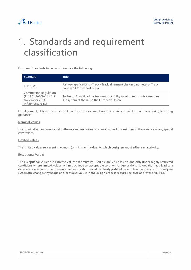
European Standards to be considered are the following:
Standard Title
EN 13803 Railway applications - Track - Track alignment design parameters - Track gauges 1435mm and wider
Commission Regulation (EU) N° 1299/2014 of 18 November 2014 – Infrastructure TSI
Technical Specifications for Interoperability relating to the infrastructure subsystem of the rail in the European Union.
For alignment, different values are defined in this document and these values shall be read considering following guidance: Nominal Values The nominal values correspond to the recommend values commonly used by designers in the absence of any special constraints. Limited Values The limited values represent maximum (or minimum) values to which designers must adhere as a priority. Exceptional Values The exceptional values are extreme values that must be used as rarely as possible and only under highly restricted conditions where limited values will not achieve an acceptable solution. Usage of these values that may lead to a deterioration in comfort and maintenance conditions must be clearly justified by significant issues and must require systematic change. Any usage of exceptional values in the design process requires ex-ante approval of RB Rail.
Design guidelines Railway Alignment
RBDG-MAN-013-0105 page 5/21
General rules related to geometry Element limitation For better freight train operations and passenger comfort, the number of vertical elements is recommended to be limited to 4 per sliding kilometre (vertical curves or slopes with constant gradient) and recommended minimum distance between sag and crest of vertical profile is 600m. Horizontal and vertical interference Overlapping of vertical curves with horizontal transition curves or turnouts is not recommended. Turnouts shall not overlap with vertical curves in case if the design speed is higher than 200 km/h. In case of overlapping of horizontal transition curves or turnouts with vertical curves the radius of vertical curve shall be recommended value or higher. At main tracks minimum recommended distance between start/end of horizontal element and start/end of vertical element is 30m. Maximum radius value For practical reasons curve values are limited:
The maximum horizontal curve is limited to 25 000m
The maximum vertical curve is limited to 40 000m
Design of railway alignment in correspondence with maximum operational speed
Railway alignment, including station layouts, should be designed as straight as possible.
Railway alignment in urban areas in proximity to international passenger stations
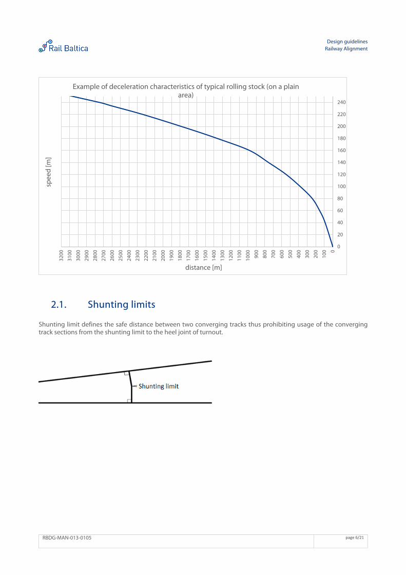
In case if in urban areas due to technical, environmental or other constraints minimum allowed value of horizontal radius cannot be provided, speed limit may be introduced. The speed limit shall follow typical braking curve of passenger trains.
Design guidelines Railway Alignment
RBDG-MAN-013-0105 page 6/21
2.1. Shunting limits
Shunting limit defines the safe distance between two converging tracks thus prohibiting usage of the converging track sections from the shunting limit to the heel joint of turnout.
0
20
40
60
80
100
120
140
160
180
200
220
240
0
100
200
300
400
500
600
700
800
900
1000
1100
1200
1300
1400
1500
1600
1700
1800
1900
2000
2100
2200
2300
2400
2500
2600
2700
2800
2900
3000
3100
3200
spee
d [m
]
distance [m]
Example of deceleration characteristics of typical rolling stock (on a plain area)
Design guidelines Railway Alignment
RBDG-MAN-013-0105 page 7/21
Shunting limits when both tracks are straight
Passenger and light traffic sections designed for GC gauge
In turnout areas of passenger and light freight traffic sections designed to GC gauge, the shunting limits shall be located at places where distance between straight tracks axis is at least 3,60 m.
Mixed traffic sections designed for SEc gauge
At mixed traffic sections designed to SEc gauge, the shunting limits shall be located at places where distance between straight tracks axis is at least:
4,10 m between main tracks and between main track and side track
3,90 m between side tracks
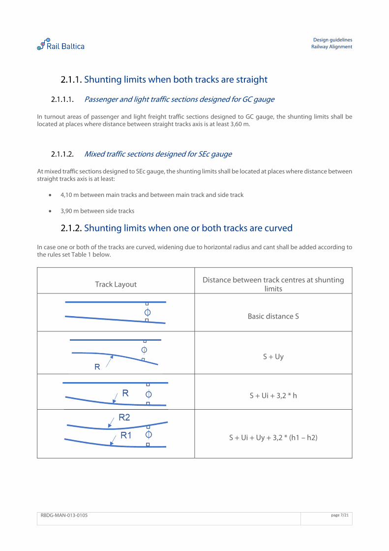
Shunting limits when one or both tracks are curved
In case one or both of the tracks are curved, widening due to horizontal radius and cant shall be added according to the rules set Table 1 below.
Track Layout Distance between track centres at shunting
limits
Basic distance S
S + Uy
S + Ui + 3,2 * h
S + Ui + Uy + 3,2 * (h1 – h2)
Design guidelines Railway Alignment
RBDG-MAN-013-0105 page 8/21
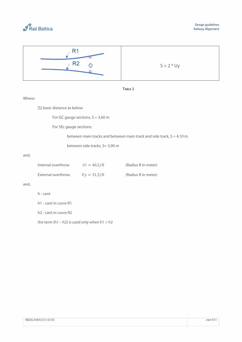
S + 2 * Uy
TABLE 1
Where:
[S] basic distance as below:
For GC gauge sections, S = 3,60 m
For SEc gauge sections:
between main tracks and between main track and side track, S = 4,10 m
between side tracks, S= 3,90 m
and,
Internal overthrow 𝑈𝑖 40,5/𝑅 (Radius R in meter)
External overthrow 𝑈𝑦 31,5/𝑅 (Radius R in meter)
and,
h - cant
h1 - cant in curve R1
h2 - cant in curve R2
the term (h1 – h2) is used only when h1 > h2
Design guidelines Railway Alignment
RBDG-MAN-013-0105 page 9/21
Part 1 - Mixed Traffic Line Mixed traffic line parameters:
Passenger trains: V = 249km/h
Freight trains: V = 120km/h
General plan characteristics 3.1. Cant (D)
The limited value for cant (maximum cant) is 90mm. The exceptional value is 110mm (for exceptional values use, refer to chapter 1).
3.2. Cant excess (E)
The limited value for cant excess (E) (maximum cant excess) is 90mm. The exceptional value is 105mm (for exceptional values use, refer to chapter 1).
3.3. Cant deficiency (I)
The limited value for cant deficiency (I) (maximum cant deficiency) is 100mm. The exceptional value is 115mm (for exceptional values use, refer to chapter 1).
Design guidelines Railway Alignment
RBDG-MAN-013-0105 page 10/21
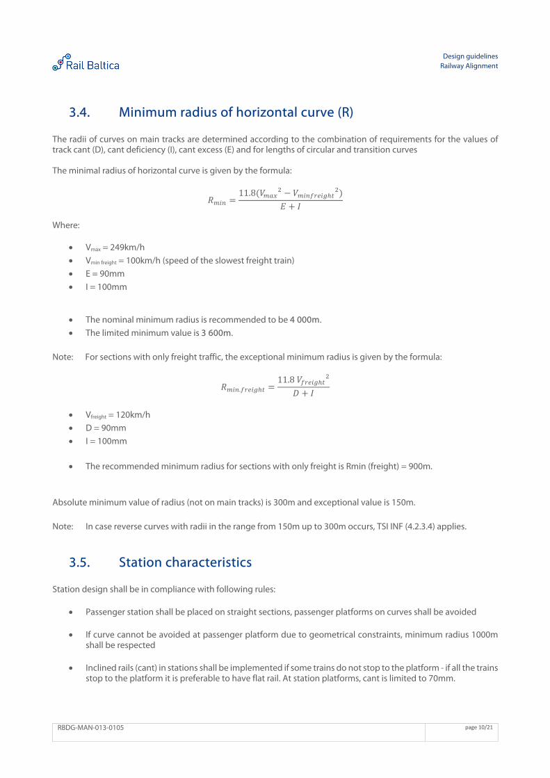
3.4. Minimum radius of horizontal curve (R)
The radii of curves on main tracks are determined according to the combination of requirements for the values of track cant (D), cant deficiency (I), cant excess (E) and for lengths of circular and transition curves The minimal radius of horizontal curve is given by the formula:
𝑅11.8 𝑉 𝑉
𝐸 𝐼
Where:
Vmax = 249km/h
Vmin freight = 100km/h (speed of the slowest freight train)
E = 90mm
I = 100mm
The nominal minimum radius is recommended to be 4 000m.
The limited minimum value is 3 600m. Note: For sections with only freight traffic, the exceptional minimum radius is given by the formula:
𝑅 .11.8 𝑉
𝐷 𝐼
Vfreight = 120km/h
D = 90mm
I = 100mm
The recommended minimum radius for sections with only freight is Rmin (freight) = 900m. Absolute minimum value of radius (not on main tracks) is 300m and exceptional value is 150m. Note: In case reverse curves with radii in the range from 150m up to 300m occurs, TSI INF (4.2.3.4) applies.
3.5. Station characteristics
Station design shall be in compliance with following rules:
Passenger station shall be placed on straight sections, passenger platforms on curves shall be avoided
If curve cannot be avoided at passenger platform due to geometrical constraints, minimum radius 1000m shall be respected
Inclined rails (cant) in stations shall be implemented if some trains do not stop to the platform - if all the trains stop to the platform it is preferable to have flat rail. At station platforms, cant is limited to 70mm.
Design guidelines Railway Alignment
RBDG-MAN-013-0105 page 11/21
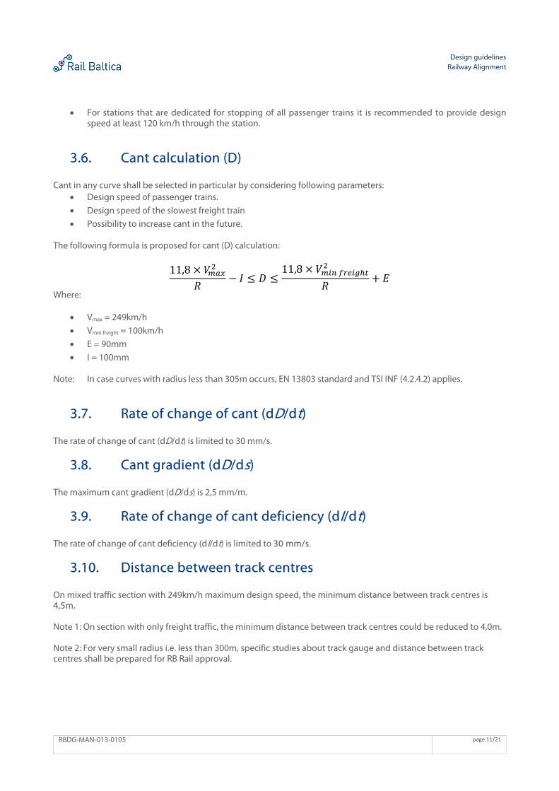
For stations that are dedicated for stopping of all passenger trains it is recommended to provide design speed at least 120 km/h through the station.
3.6. Cant calculation (D)
Cant in any curve shall be selected in particular by considering following parameters: Design speed of passenger trains.
Design speed of the slowest freight train
Possibility to increase cant in the future.
The following formula is proposed for cant (D) calculation:
11,8 𝑉𝑅
𝐼 𝐷11,8 𝑉
𝑅𝐸
Where:
Vmax = 249km/h
Vmin freight = 100km/h
E = 90mm
I = 100mm
Note: In case curves with radius less than 305m occurs, EN 13803 standard and TSI INF (4.2.4.2) applies.
3.7. Rate of change of cant (dD/dt)
The rate of change of cant (dD/dt) is limited to 30 mm/s.
3.8. Cant gradient (dD/ds)
The maximum cant gradient (dD/ds) is 2,5 mm/m.
3.9. Rate of change of cant deficiency (dI/dt)
The rate of change of cant deficiency (dI/dt) is limited to 30 mm/s.
3.10. Distance between track centres
On mixed traffic section with 249km/h maximum design speed, the minimum distance between track centres is 4,5m. Note 1: On section with only freight traffic, the minimum distance between track centres could be reduced to 4,0m. Note 2: For very small radius i.e. less than 300m, specific studies about track gauge and distance between track centres shall be prepared for RB Rail approval.
Design guidelines Railway Alignment
RBDG-MAN-013-0105 page 12/21
3.11. Length of straight elements and horizontal circular curves
At main tracks, minimum length of straight elements and horizontal circular curves given in meters shall adhere to the following limits:
Recommended value: L ≥ Vmax/1,2
Limited value: L ≥ Vmax/1,5
Exceptional value: L ≥ Vmax/2 (for exceptional values use, refer to chapter 1) Note: Vmax is inserted in definite units (km/h).
Design guidelines Railway Alignment
RBDG-MAN-013-0105 page 13/21
3.12. Length of transition curve (LK)
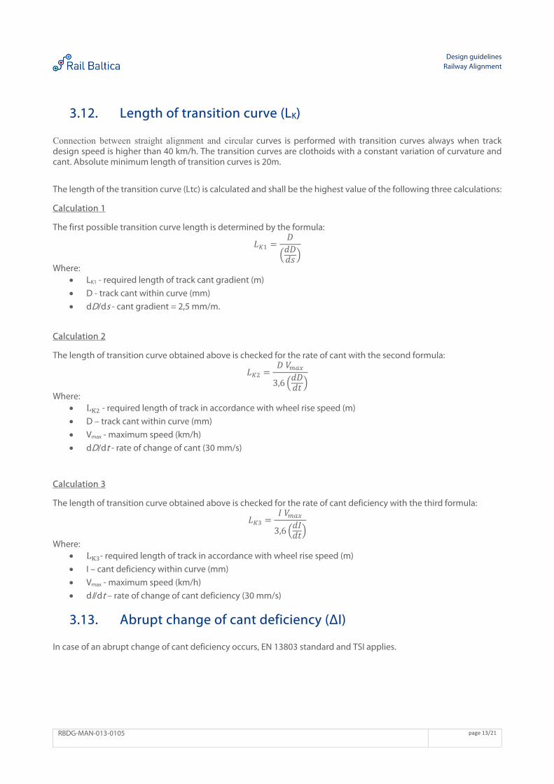
Connection between straight alignment and circular curves is performed with transition curves always when track design speed is higher than 40 km/h. The transition curves are clothoids with a constant variation of curvature and cant. Absolute minimum length of transition curves is 20m. The length of the transition curve (Ltc) is calculated and shall be the highest value of the following three calculations: Calculation 1 The first possible transition curve length is determined by the formula:
𝐿𝐷𝑑𝐷𝑑𝑠
Where: LK1 - required length of track cant gradient (m)
D - track cant within curve (mm)
dD/ds - cant gradient = 2,5 mm/m.
Calculation 2 The length of transition curve obtained above is checked for the rate of cant with the second formula:
𝐿𝐷 𝑉
3,6𝑑𝐷𝑑𝑡
Where: L - required length of track in accordance with wheel rise speed (m)
D – track cant within curve (mm)
Vmax - maximum speed (km/h)
dD/dt - rate of change of cant (30 mm/s)
Calculation 3 The length of transition curve obtained above is checked for the rate of cant deficiency with the third formula:
𝐿𝐼 𝑉
3,6𝑑𝐼𝑑𝑡
Where: L - required length of track in accordance with wheel rise speed (m)
I – cant deficiency within curve (mm)
Vmax - maximum speed (km/h)
dI/dt – rate of change of cant deficiency (30 mm/s)
3.13. Abrupt change of cant deficiency (ΔI)
In case of an abrupt change of cant deficiency occurs, EN 13803 standard and TSI applies.
Design guidelines Railway Alignment
RBDG-MAN-013-0105 page 14/21
General vertical characteristics 4.1. Gradient (p)
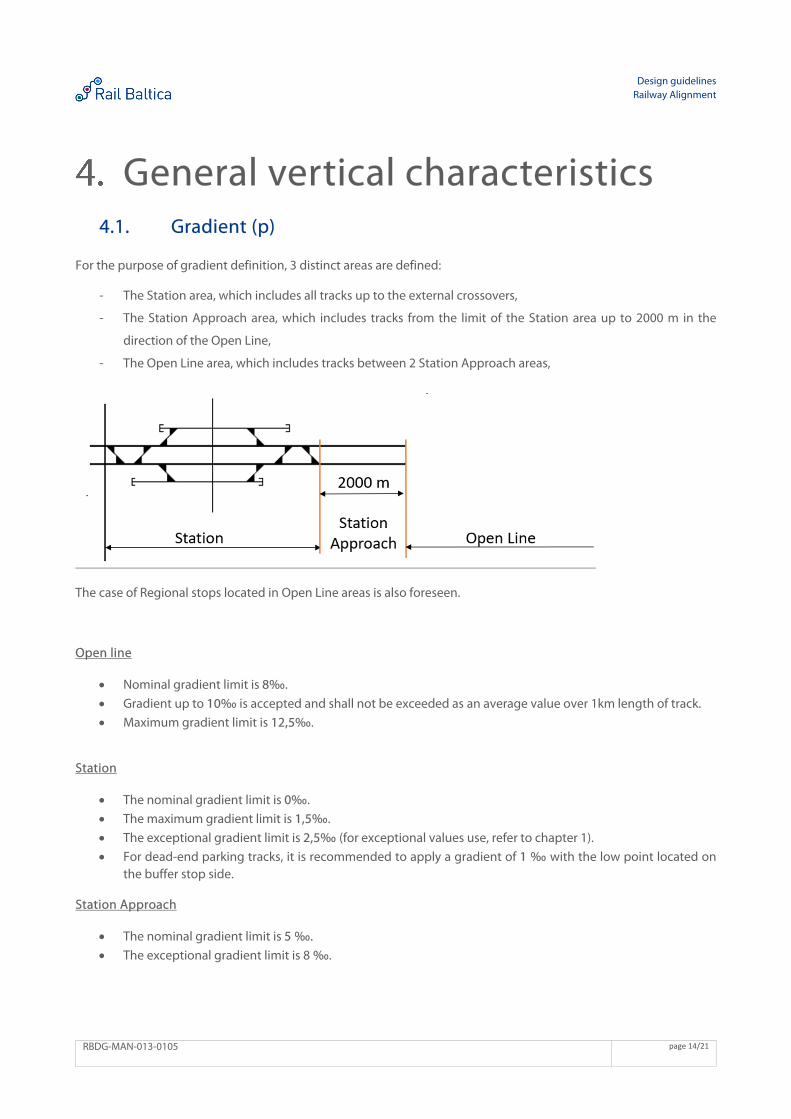
For the purpose of gradient definition, 3 distinct areas are defined:
- The Station area, which includes all tracks up to the external crossovers,
- The Station Approach area, which includes tracks from the limit of the Station area up to 2000 m in the
direction of the Open Line,
- The Open Line area, which includes tracks between 2 Station Approach areas,
The case of Regional stops located in Open Line areas is also foreseen. Open line
Nominal gradient limit is 8‰.
Gradient up to 10‰ is accepted and shall not be exceeded as an average value over 1km length of track.
Maximum gradient limit is 12,5‰.
Station
The nominal gradient limit is 0‰.
The maximum gradient limit is 1,5‰.
The exceptional gradient limit is 2,5‰ (for exceptional values use, refer to chapter 1).
For dead-end parking tracks, it is recommended to apply a gradient of 1 ‰ with the low point located on the buffer stop side.
Station Approach
The nominal gradient limit is 5 ‰.
The exceptional gradient limit is 8 ‰.
Design guidelines Railway Alignment
RBDG-MAN-013-0105 page 15/21
Regional stops in Open line area
The maximal gradient limit is 5 ‰.
Note: Regional stop located in Open Line area is a passenger stop, with lateral platforms without any stabling tracks (no parking of the rolling stock allowed), where no coupling operations are possible (vehicles are not intended to be attached or detached).
4.2. Radius of vertical curve (RV)
Recommended value RV = 0,6 Vmax2
Minimum value RV = 0,35 Vmax2
Exceptional value RV = 0,25 Vmax2
Two tangents need to be connected with circular vertical curve (not parabolic) if the value of abrupt change of track gradient is higher than upper limits described in EN 13803. The absolute minimum radius of vertical curve is the following:
Minimum value for main tracks 10 000m.
Minimum value for other tracks 2000m.
4.3. Length of vertical radius (LV) and constant gradient (Lg)
Minimum length of vertical radius and constant gradient is:
Nominal value Vmax/2
Minimum value Vmax/2,5
Exceptional absolute minimum value 30m (for exceptional values use, refer to chapter 1)
Design guidelines Railway Alignment
RBDG-MAN-013-0105 page 16/21
Part 2 - Passenger only and Light Freight Traffic Line
Maximum design speed for passenger trains is 249km/h.
General plan characteristics 5.1. Cant
The limited value for cant (maximum cant) is 160mm. The exceptional value is 180mm (for exceptional values use, refer to chapter 1).
5.2. Cant excess (E)
The limited value for cant excess (E) (maximum cant excess) is 90mm. The exceptional value is 110mm (for exceptional values use, refer to chapter 1).
5.3. Cant deficiency (I)
The limited value for cant deficiency (I) (maximum cant deficiency) is 110mm. The exceptional value is 130mm (for exceptional values use, refer to chapter 1).
Design guidelines Railway Alignment
RBDG-MAN-013-0105 page 17/21
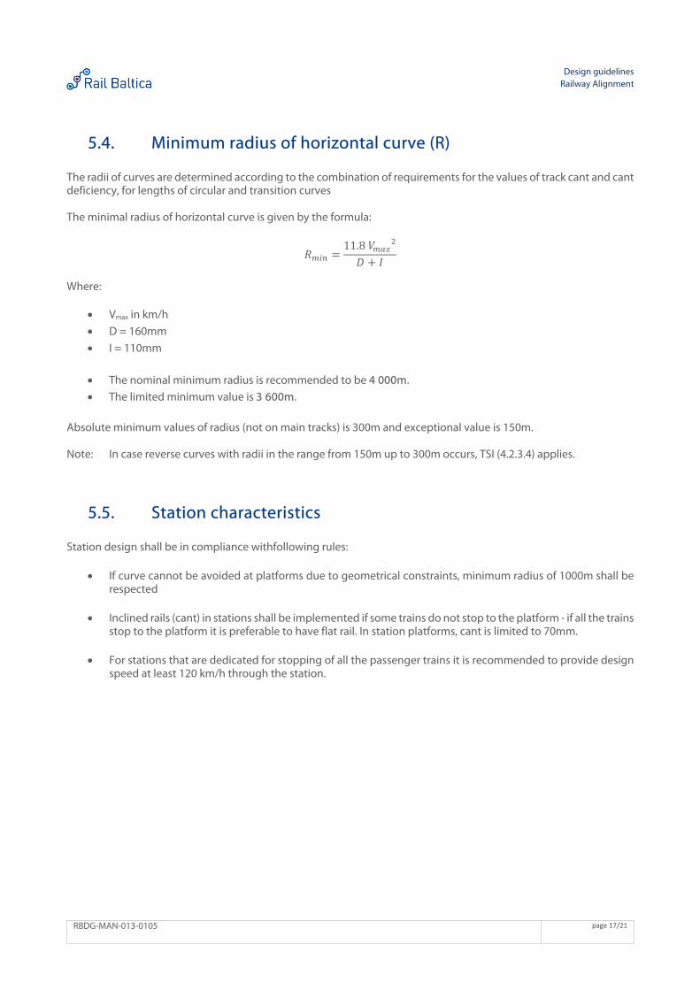
5.4. Minimum radius of horizontal curve (R)
The radii of curves are determined according to the combination of requirements for the values of track cant and cant deficiency, for lengths of circular and transition curves The minimal radius of horizontal curve is given by the formula:
𝑅11.8 𝑉𝐷 𝐼
Where:
Vmax in km/h
D = 160mm
I = 110mm
The nominal minimum radius is recommended to be 4 000m.
The limited minimum value is 3 600m.
Absolute minimum values of radius (not on main tracks) is 300m and exceptional value is 150m. Note: In case reverse curves with radii in the range from 150m up to 300m occurs, TSI (4.2.3.4) applies.
5.5. Station characteristics
Station design shall be in compliance withfollowing rules:
If curve cannot be avoided at platforms due to geometrical constraints, minimum radius of 1000m shall be respected
Inclined rails (cant) in stations shall be implemented if some trains do not stop to the platform - if all the trains stop to the platform it is preferable to have flat rail. In station platforms, cant is limited to 70mm.
For stations that are dedicated for stopping of all the passenger trains it is recommended to provide design speed at least 120 km/h through the station.
Design guidelines Railway Alignment
RBDG-MAN-013-0105 page 18/21
5.6. Cant calculation (D)
Cant calculation formula:
Cant (D) = 11,8 V2/R with V in km/h.
V is defined as average weighted actual speed of rolling stock.
5.7. Rate of change of cant (dD/dt)
The rate of change of cant (dD/dt) is limited to 45 mm/s.
5.8. Cant gradient (dD/ds)
The maximum cant gradient (dD/ds) is 2,5 mm/m.
5.9. Rate of change of cant deficiency (dI/dt)
The rate of change of cant deficiency (dI/dt) is limited to 45 mm/s.
5.10. Distance between track centres
On passenger only and light freight traffic section with 249km/h maximum design speed, the minimum distance between track centres is 4,5m. On only passenger traffic section with 200km/h maximum design speed, the minimum distance between track centres is 3,80 m with a preferred value of 4,00 m. Note: For very small radius i.e. less than 300m, specific studies about track gauge and distance between track centres shall be prepared for RB Rail approval. At sections where the minimum distance between track centres is less than 4,00 m, no turnout shall be installed.
5.11. Length of straight elements and horizontal circular curves
For main tracks, minimum length of straight elements and horizontal circular curves given in meters shall adhere to the following limits:
Limited value: L ≥ V/2
Exceptional value: L ≥ V/3 (for exceptional values use, refer to chapter 1) with V = 249km/h
Design guidelines Railway Alignment
RBDG-MAN-013-0105 page 19/21
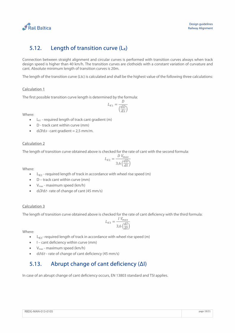
5.12. Length of transition curve (LK)
Connection between straight alignment and circular curves is performed with transition curves always when track design speed is higher than 40 km/h. The transition curves are clothoids with a constant variation of curvature and cant. Absolute minimum length of transition curves is 20m. The length of the transition curve (Ltc) is calculated and shall be the highest value of the following three calculations: Calculation 1 The first possible transition curve length is determined by the formula:
𝐿𝐷𝑑𝐷𝑑𝑠
Where: LK1 - required length of track cant gradient (m)
D - track cant within curve (mm)
dD/ds - cant gradient = 2,5 mm/m.
Calculation 2 The length of transition curve obtained above is checked for the rate of cant with the second formula:
𝐿𝐷 𝑉
3,6𝑑𝐷𝑑𝑡
Where: L - required length of track in accordance with wheel rise speed (m)
D – track cant within curve (mm)
Vmax - maximum speed (km/h)
dD/dt - rate of change of cant (45 mm/s)
Calculation 3 The length of transition curve obtained above is checked for the rate of cant deficiency with the third formula:
𝐿𝐼 𝑉
3,6𝑑𝐼𝑑𝑡
Where: L - required length of track in accordance with wheel rise speed (m)
I – cant deficiency within curve (mm)
Vmax - maximum speed (km/h)
dI/dt – rate of change of cant deficiency (45 mm/s)
5.13. Abrupt change of cant deficiency (ΔI)
In case of an abrupt change of cant deficiency occurs, EN 13803 standard and TSI applies.
Design guidelines Railway Alignment
RBDG-MAN-013-0105 page 20/21
General vertical characteristics 6.1. Gradient (p)
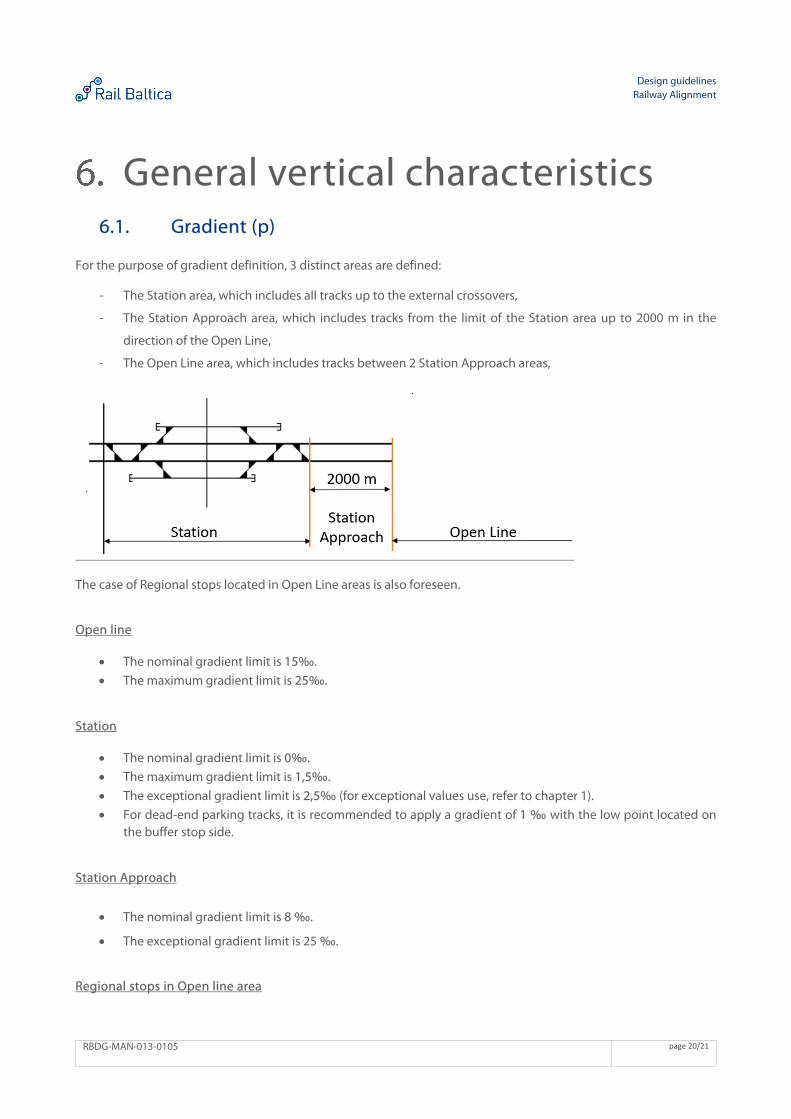
For the purpose of gradient definition, 3 distinct areas are defined:
- The Station area, which includes all tracks up to the external crossovers,
- The Station Approach area, which includes tracks from the limit of the Station area up to 2000 m in the
direction of the Open Line,
- The Open Line area, which includes tracks between 2 Station Approach areas,
The case of Regional stops located in Open Line areas is also foreseen. Open line
The nominal gradient limit is 15‰.
The maximum gradient limit is 25‰.
Station
The nominal gradient limit is 0‰.
The maximum gradient limit is 1,5‰.
The exceptional gradient limit is 2,5‰ (for exceptional values use, refer to chapter 1).
For dead-end parking tracks, it is recommended to apply a gradient of 1 ‰ with the low point located on the buffer stop side.
Station Approach
The nominal gradient limit is 8 ‰.
The exceptional gradient limit is 25 ‰.
Regional stops in Open line area
Design guidelines Railway Alignment
RBDG-MAN-013-0105 page 21/21
The maximal gradient limit is 5 ‰.
Note: Regional stop located in Open Line area is a passenger stop, with lateral platforms without any stabling tracks (no parking of the rolling stock allowed), where no coupling operations are possible (vehicles are not intended to be attached or detached).
6.2. Radius of vertical curve (RV)
Recommended value RV = 0.6 Vmax2
Minimum value RV = 0.35 Vmax2
Exceptional value RV = 0.25 Vmax2
Two tangents need to be connected with circular vertical curve (not parabolic) if the value of abrupt change of track gradient is higher than upper limits described in EN 13803. The absolute minimum radius of vertical curve is the following:
Minimum value for main tracks 10 000m.
Minimum value for other tracks is 2000m.
6.3. Circular vertical curve (LV)
Minimum length of vertical radius and constant gradient is:
Nominal value Vmax/2
Minimum value Vmax/2,5
Exceptional absolute minimum value 30m (for exceptional values use, refer to chapter 1)
Related Documents