1 This document explains how to install CX4 series hardware in cabinets that conform to the National Electrical Manufacturer’s Association (NEMA) standards for 19-inch cabinets (in which the left and right mounting channels are 19 inches apart). It covers mounting hardware for 1U, 2U, 3U and 4U components, and filler panels that cover empty cabinet spaces. In most cases, the illustrations and examples refer to EMC ® standard cabinets, which are 40U tall. Topics are: ◆ Device placement requirements ......................................................... 2 ◆ Power requirements ............................................................................. 4 ◆ Device height requirements ................................................................ 4 ◆ Installing a 1U SPS tray and SPS units in a cabinet ......................... 6 ◆ Installing a 2U storage processor enclosure (SPE) in a cabinet.... 13 ◆ Installing a 2U SPS tray (100-561-369) and SPS units in a cabinet 20 ◆ Installing a 2U SPS tray (106-561-015) and SPS units in a cabinet 30 ◆ Installing a 4U storage processor enclosure (SPE) in a cabinet.... 40 ◆ Installing a 3U disk enclosure (DAE) in a cabinet ......................... 50 ◆ Installing front filler panels ............................................................... 57 Note: Since EMC uses easily adjustable universal rails to mount these items in a NEMA-standard cabinet, the instructions in this guide apply to non-EMC cabinets as well. Instructions for adding switches to an EMC storage system are included in the device-specific documentation that accompanies the switch. EMC Rails and Enclosures (CX4 Series Storage Systems) Field Installation Guide P/N 300-007-436 REV A02 August 13, 2008

Welcome message from author
This document is posted to help you gain knowledge. Please leave a comment to let me know what you think about it! Share it to your friends and learn new things together.
Transcript
1
This document explains how to install CX4 series hardware in cabinets that conform to the National Electrical Manufacturer’s Association (NEMA) standards for 19-inch cabinets (in which the left and right mounting channels are 19 inches apart). It covers mounting hardware for 1U, 2U, 3U and 4U components, and filler panels that cover empty cabinet spaces. In most cases, the illustrations and examples refer to EMC® standard cabinets, which are 40U tall.
Topics are:
◆ Device placement requirements ......................................................... 2◆ Power requirements ............................................................................. 4◆ Device height requirements ................................................................ 4◆ Installing a 1U SPS tray and SPS units in a cabinet......................... 6◆ Installing a 2U storage processor enclosure (SPE) in a cabinet.... 13◆ Installing a 2U SPS tray (100-561-369) and SPS units in a cabinet 20◆ Installing a 2U SPS tray (106-561-015) and SPS units in a cabinet 30◆ Installing a 4U storage processor enclosure (SPE) in a cabinet.... 40◆ Installing a 3U disk enclosure (DAE) in a cabinet ......................... 50◆ Installing front filler panels............................................................... 57
Note: Since EMC uses easily adjustable universal rails to mount these items in a NEMA-standard cabinet, the instructions in this guide apply to non-EMC cabinets as well.
Instructions for adding switches to an EMC storage system are included in the device-specific documentation that accompanies the switch.
EMCRails and Enclosures
(CX4 Series Storage Systems)
Field Installation GuideP/N 300-007-436
REV A02
August 13, 2008

2 EMC Rails and Enclosures (CX4 Series Storage Systems) Field Installation Guide
Device placement requirements
Device placement requirementsThis document provides the steps required to install rails and enclosures in both EMC and non-EMC cabinets. Unless otherwise specified, the illustrations depict the EMC 40U and 40U-C cabinet.
Figure 1 Typical cabinet front and rear views
Before attaching the mounting rails or trays in any cabinet, you must decide where to put them. Where you install the devices depends on the kinds of devices you will install and the height of each device.
EMC2203Front Rear

EMC Rails and Enclosures (CX4 Series Storage Systems) Field Installation Guide 3
Device placement requirements
Position in the cabinetDevices with internal cooling fans or blowers that move air from front to back (or vice versa) and not from beneath or above have no special cooling requirements that direct placement in the cabinet. All of the storage systems and enclosures mentioned in this document have fans or blowers that move air from front to back.
In most cases, you should install devices starting at the bottom of the cabinet. Installing bottom to top offers the advantages of stability and convenient cable access from beneath.
We recommend that you arrange your enclosure as follows:
◆ Install the standby power supply (SPS) below any other enclosures (at the bottom of an empty cabinet).
◆ Install the SPE (storage processor enclosure) directly above the SPS.
◆ Install the specially marked disk-array enclosure (DAE)-OS directly above the SPE.
◆ Install any additional disk enclosures above the DAE-OS.
Review your plan to make sure all devices will fit in the cabinet, and review any requirements for filler panels. It is also important to verify cabling lengths before installing any enclosure.

4 EMC Rails and Enclosures (CX4 Series Storage Systems) Field Installation Guide
Power requirements
Power requirementsPower distribution must support the number of outlets required for the device and the device power rating.
For example, each pair of power distribution panels (PDP) in the EMC standard 40U-C cabinet can support a maximum of 24 A AC current draw from devices connected to its power distribution units (PDU). Most cabinet configurations draw less than 24 A AC power, and require only two discrete 240 V AC power sources. If the total AC current draw of all the devices in a single cabinet exceeds 24 A, the cabinet requires two additional 240 V power sources to support a second pair of PDPs. Use the published technical specifications and device rating labels to determine the current draw of each device in your cabinet and calculate the total.
Note: For high availability, the left and right sides of any rack or cabinet must receive power from separate branch feed circuits.
Device height requirementsDevice height requirements and cabinet mounting measurements are based on NEMA units (U’s). See Table 1.
The predrilled holes in the cabinet channels are based on the U measurement. The holes are predrilled at distances of 1/2 inch, 5/8 inch, 5/8 inch (totaling one U), then 1/2 inch, 5/8 inch, 5/8 inch (another U), and so on. On EMC 40U and 40U-C cabinets, the 1U increments are marked by a horizontal line or small hole in the channel. See Figure 2 on the next page.
Table 1 NEMA unit heights
Number of U’s Actual height
1U 1-3/4 inches
2U 3-1/2 inches
3U 5-1/4 inches
4U 7 inches

EMC Rails and Enclosures (CX4 Series Storage Systems) Field Installation Guide 5
Device height requirements
Table 2 lists the vertical space requirements of typical rackmounted devices.
Figure 2 U increments in a 40U cabinet front channel
Table 2 Height requirements of typical devices
HeightNumber of cabinet channel holes Typical device example
1U, 1-3/4 in, 45 mm 3 CX4-120/240/480 SPS; some switches
2U, 3-1/2 in,90 mm 6 CX4-120/240/480 SPE, CX4-960 SPS;some switches
3U, 5-1/4 in, 133 mm 9 EMC DAE
4U, 7 in, 178 mm 12 CX4-960 SPE
EMC2205
1
2
3
4
5
6
7
8
1U (1.75-in.)Increment

6 EMC Rails and Enclosures (CX4 Series Storage Systems) Field Installation Guide
Installing a 1U SPS tray and SPS units in a cabinet
Installing a 1U SPS tray and SPS units in a cabinetThis section explains how to install a 1U SPS (standby power supply) tray in the cabinet. Your storage processor enclosure may require one or two 1U SPS units in a single 1U tray.
SPS mounting kit The SPS mounting kit includes the components listed in Table 3.
Table 3 SPS mounting materials
Component Use
2 adjustable (20.5-34 inches) rails
Attach front to back on either side between NEMA channels
SPS B filler unit For configurations with a single SPS unit, covers opening in back of tray
SPS tray - see Figure 6 on page 10 For one or two SPSs
Front fastener bracket
Secure SPS units to tray
M4 x 8-mm panhead screw, lock washer,and flat washer assemblies
For back of tray
M4 x 10-mm flathead screwsFor front of tray and fastener bracket
2 latch brackets
Secure 1U bezel
EMC3298
EMC Rails and Enclosures (CX4 Series Storage Systems) Field Installation Guide 7
Installing a 1U SPS tray and SPS units in a cabinet
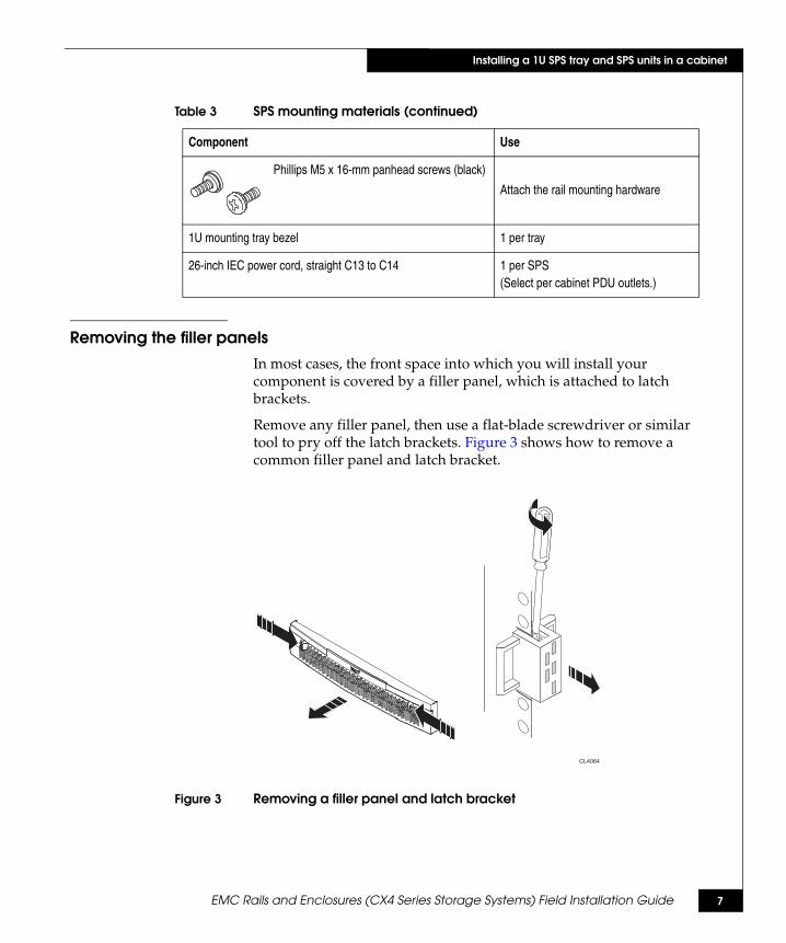
Removing the filler panelsIn most cases, the front space into which you will install your component is covered by a filler panel, which is attached to latch brackets.
Remove any filler panel, then use a flat-blade screwdriver or similar tool to pry off the latch brackets. Figure 3 shows how to remove a common filler panel and latch bracket.
Figure 3 Removing a filler panel and latch bracket
Phillips M5 x 16-mm panhead screws (black)
Attach the rail mounting hardware
1U mounting tray bezel 1 per tray
26-inch IEC power cord, straight C13 to C14 1 per SPS(Select per cabinet PDU outlets.)
Table 3 SPS mounting materials (continued)
Component Use
CL4064

8 EMC Rails and Enclosures (CX4 Series Storage Systems) Field Installation Guide
Installing a 1U SPS tray and SPS units in a cabinet
Installing the rails in the cabinetThis section describes how to mount the rails in the cabinet.
1. After you decide where in the cabinet you want to install the SPS tray, find the unoccupied 1U section on the rear channels. We suggest that you install the SPS tray immediately above the SPE, if possible.
2. From the front of the cabinet, insert the alignment pin on one mounting rail assembly into the middle hole of the selected 1U space on a rear channel. Figure 4 shows the correct channel holes for the alignment pins.
Figure 4 Aligning pins in a 1U section on the cabinet rear rails
Refer to Figure 5 on page 9 as you perform steps 3 and 4.
3. Extend the rail to the front cabinet channel. Align the holes of the front rail flange to the inside of the channel, ensure that the rail is level, and then install two M5 x 16-mm Phillips securing screws in the top and bottom holes, as shown in Figure 5.
Note: Leave the screws slightly loose to allow for adjustment after you install the tray. Do not insert a screw in the middle hole yet.
1U
Alignment PinHere
EMC2922
EMC Rails and Enclosures (CX4 Series Storage Systems) Field Installation Guide 9
Installing a 1U SPS tray and SPS units in a cabinet
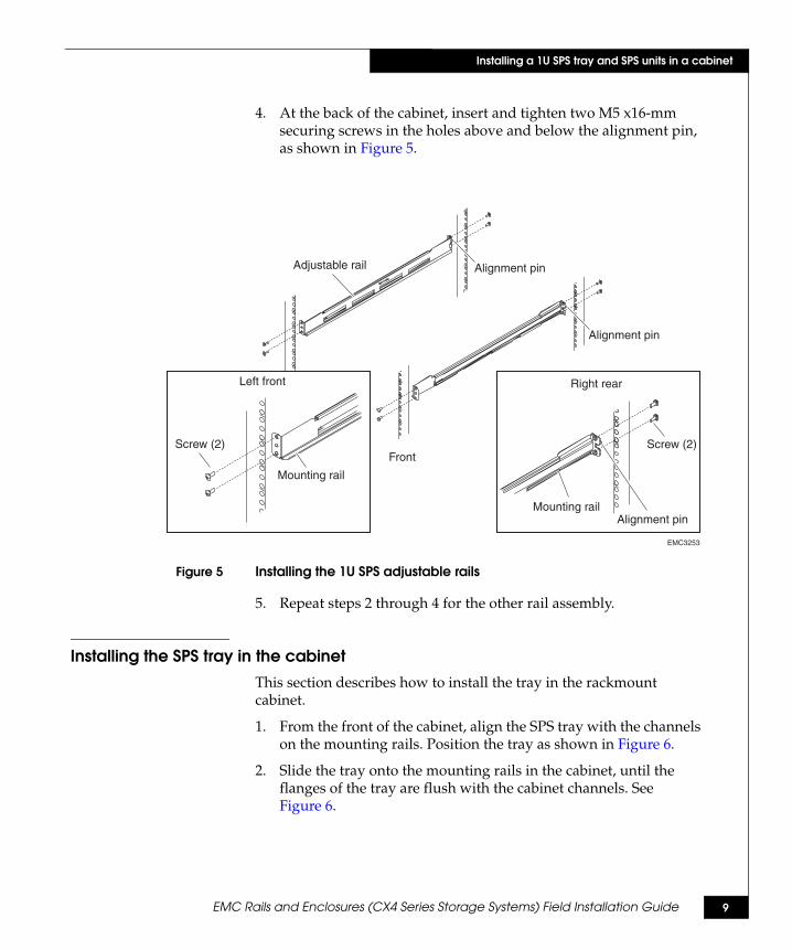
4. At the back of the cabinet, insert and tighten two M5 x16-mm securing screws in the holes above and below the alignment pin, as shown in Figure 5.
Figure 5 Installing the 1U SPS adjustable rails
5. Repeat steps 2 through 4 for the other rail assembly.
Installing the SPS tray in the cabinetThis section describes how to install the tray in the rackmount cabinet.
1. From the front of the cabinet, align the SPS tray with the channels on the mounting rails. Position the tray as shown in Figure 6.
2. Slide the tray onto the mounting rails in the cabinet, until the flanges of the tray are flush with the cabinet channels. See Figure 6.
EMC3253
Adjustable rail Alignment pin
Alignment pin
Front
Left front
Screw (2)
Mounting rail
Right rear
Screw (2)
Mounting railAlignment pin
10 EMC Rails and Enclosures (CX4 Series Storage Systems) Field Installation Guide
Installing a 1U SPS tray and SPS units in a cabinet
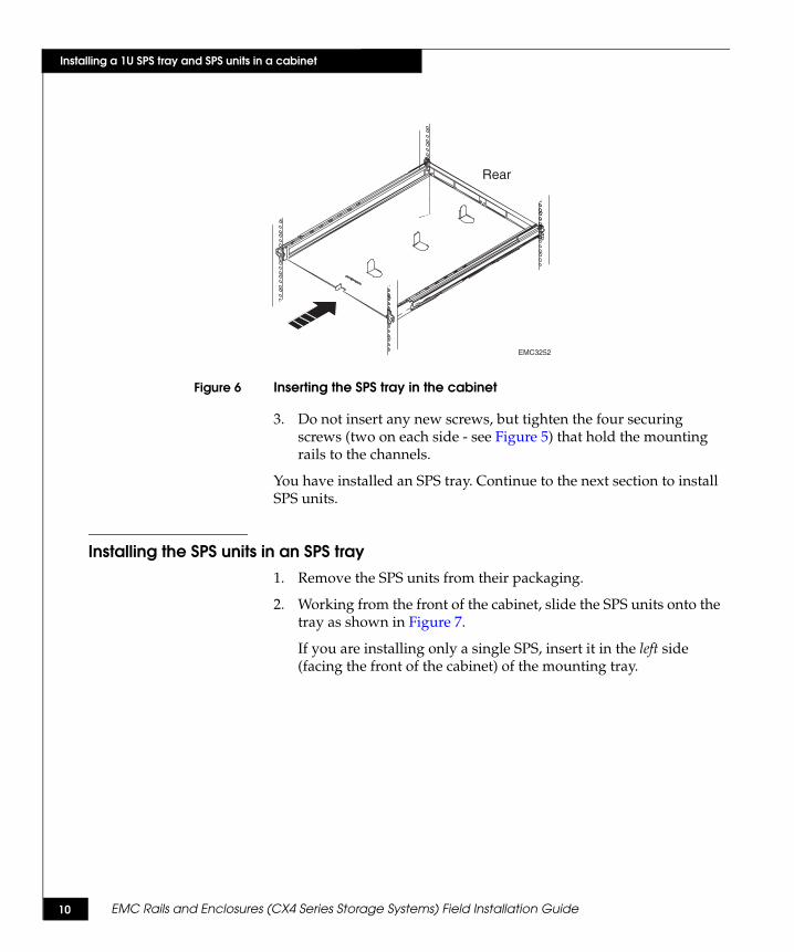
Figure 6 Inserting the SPS tray in the cabinet
3. Do not insert any new screws, but tighten the four securing screws (two on each side - see Figure 5) that hold the mounting rails to the channels.
You have installed an SPS tray. Continue to the next section to install SPS units.
Installing the SPS units in an SPS tray1. Remove the SPS units from their packaging.
2. Working from the front of the cabinet, slide the SPS units onto the tray as shown in Figure 7.
If you are installing only a single SPS, insert it in the left side (facing the front of the cabinet) of the mounting tray.
EMC3252
Rear

EMC Rails and Enclosures (CX4 Series Storage Systems) Field Installation Guide 11
Installing a 1U SPS tray and SPS units in a cabinet
Figure 7 Inserting the SPS units into the SPS tray
Note: To eliminate potential bow caused by the weight of the SPS(s), press up on the middle of the tray with one hand while you secure the units to the tray. (The tray will not bow if placed on the bottom of the cabinet.)
3. Attach the front fastening bracket, and insert and tighten the six M4 x 10-mm flathead securing screws as shown in Figure 7.
4. Insert and tighten the eight M4 x 8-mm panhead securing screws that secure the SPS units to the back of the tray, as shown in Figure 7.
Back
Front
EMC3251
Screw (6)
Screw (8)

12 EMC Rails and Enclosures (CX4 Series Storage Systems) Field Installation Guide
Installing a 1U SPS tray and SPS units in a cabinet
Installing the latch brackets and bezelThis section describes how to install latch brackets and the bezel they support.
1. Use one Phillips M5 x 16-mm screw to secure a latch bracket to each front channel. (The brackets include small alignment bumps to correctly orient them to the channel.) See Figure 8.
2. Press the bezel onto the latch brackets until it snaps into place. See Figure 8.
Figure 8 Installing the latch bracket and bezel
You have installed an SPS tray and SPS units in the cabinet.
If you are installing another device in the cabinet, continue with the appropriate instructions. For example, to add a storage processor enclosure above the SPS you just installed, refer to “Installing a 4U storage processor enclosure (SPE) in a cabinet” on page 40.
Next, cable the enclosures and SPS units as described in the appropriate setup guide.
EMC3250
Front
Rear
LatchBracket
LatchBracket

EMC Rails and Enclosures (CX4 Series Storage Systems) Field Installation Guide 13
Installing a 2U storage processor enclosure (SPE) in a cabinet
Installing a 2U storage processor enclosure (SPE) in a cabinetFollow the steps below to install a 2U SPE in a standard 19" NEMA cabinet.
Enclosure mounting kitBefore you start, be sure you have all the materials listed in Table 4. Tools are not part of your purchased enclosure assembly.
Table 4 Enclosure mounting kit materials
Component Use
2 adjustable rails (20.5-34 inches) Attach front to back on either side between NEMA channels in a standard 19" cabinet
Phillips M5 12.7 mm screws Attach the rail mounting hardware
2U bezel (front rack panel) EMI shielding
(L)
(R)
EMC3248
CLARiiON CX4-240
CL4039
14 EMC Rails and Enclosures (CX4 Series Storage Systems) Field Installation Guide
Installing a 2U storage processor enclosure (SPE) in a cabinet
Installing the adjustable rails1. Locate and unpack the rail kit that accompanied your enclosure.
The front edge of each rail is stamped L or R for left and right sides, when they face the cabinet front.
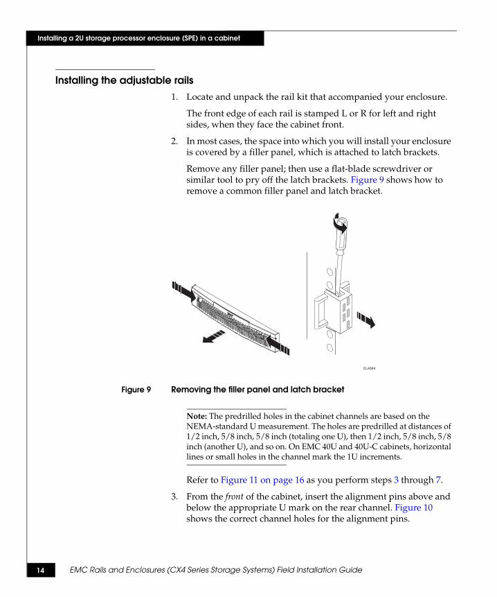
2. In most cases, the space into which you will install your enclosure is covered by a filler panel, which is attached to latch brackets.
Remove any filler panel; then use a flat-blade screwdriver or similar tool to pry off the latch brackets. Figure 9 shows how to remove a common filler panel and latch bracket.
Figure 9 Removing the filler panel and latch bracket
Note: The predrilled holes in the cabinet channels are based on the NEMA-standard U measurement. The holes are predrilled at distances of 1/2 inch, 5/8 inch, 5/8 inch (totaling one U), then 1/2 inch, 5/8 inch, 5/8 inch (another U), and so on. On EMC 40U and 40U-C cabinets, horizontal lines or small holes in the channel mark the 1U increments.
Refer to Figure 11 on page 16 as you perform steps 3 through 7.
3. From the front of the cabinet, insert the alignment pins above and below the appropriate U mark on the rear channel. Figure 10 shows the correct channel holes for the alignment pins.
CL4064

EMC Rails and Enclosures (CX4 Series Storage Systems) Field Installation Guide 15
Installing a 2U storage processor enclosure (SPE) in a cabinet
Figure 10 2U pin alignment
4. Pull the adjustable rail forward to the inner side of the front channel (the surface facing the rear of the cabinet), and align the three holes on the rail with those in the channel.
5. Secure the rail to the front channel using one of the provided screws at the bottom hole of the rail. Allow the screw to draw the rail and channel together. Leave the screw slightly loose to allow for adjustment after you install the enclosure.
6. Repeat Steps 3 through 5 on the left side, with the left rail.
7. From the rear of the cabinet, use two of the provided screws to secure each rail to the rear channel. Tighten the screws.
2U
Alignment pins
here

16 EMC Rails and Enclosures (CX4 Series Storage Systems) Field Installation Guide
Installing a 2U storage processor enclosure (SPE) in a cabinet
Figure 11 Installing the adjustable mounting rails
Front
Rear
CL4110
EMC Rails and Enclosures (CX4 Series Storage Systems) Field Installation Guide 17
Installing a 2U storage processor enclosure (SPE) in a cabinet
Installing the enclosure in the cabinet
WARNING
The enclosure is heavy and should be installed into a rack by two people. To avoid personal injury and/or damage to the equipment, do not attempt to lift and install the enclosure into a rack without a mechanical lift and/or help from another person.
L’armoire étant lourde, sa mise en place sur une rampe nécessite deux personnes. Afin de ne pas vous blesser et/ou endommager le matériel, n’essayez pas de soulever et d’installer l’armoire sur une rampe sans avoir recours à un relevage mécanique et/ou à l’aide d’une autre personne.
Das Gehäuse ist schwer und sollte nur von zwei Personen in einem Rack installiert werden. Zur Vermeidung von körperlichen Verletzungen und/oder der Beschädigung des Gerätes, bitte das Gehäuse nicht ohne die Hilfe einer zweiten Person anheben und einbauen.
Il contenitore è pesante e dev'essere installato nel rack da due persone. Per evitare danni personali e/o all’apparecchiatura, non tentare di sollevare ed installare in un rack il contenitore senza un sollevatore meccanico e/o l’aiuto di un’altra persona.
Debido a su considerable peso, la instalación del compartimento en el bastidor deben realizarla siempre dos personas. Para evitar daños personales o en el equipo, el compartimento no debe levantarse ni instalarse en el bastidor sin la ayuda de un elevador mecánico o de otra persona.
18 EMC Rails and Enclosures (CX4 Series Storage Systems) Field Installation Guide
Installing a 2U storage processor enclosure (SPE) in a cabinet
Follow these steps to install the enclosure on the rails in the cabinet:
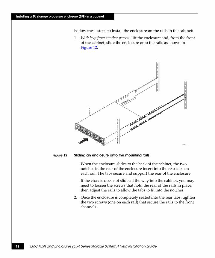
1. With help from another person, lift the enclosure and, from the front of the cabinet, slide the enclosure onto the rails as shown in Figure 12.
Figure 12 Sliding an enclosure onto the mounting rails
When the enclosure slides to the back of the cabinet, the two notches in the rear of the enclosure insert into the rear tabs on each rail. The tabs secure and support the rear of the enclosure.
If the chassis does not slide all the way into the cabinet, you may need to loosen the screws that hold the rear of the rails in place, then adjust the rails to allow the tabs to fit into the notches.
2. Once the enclosure is completely seated into the rear tabs, tighten the two screws (one on each rail) that secure the rails to the front channels.
CL4137

EMC Rails and Enclosures (CX4 Series Storage Systems) Field Installation Guide 19
Installing a 2U storage processor enclosure (SPE) in a cabinet
3. Secure the front of the enclosure to the front vertical channels of the cabinet using four M5 12.7 mm screws (two per side), as shown in Figure 13.
Note: The front screws also help to secure the latch bracket mounted on the front of the enclosure.
If you are installing the enclosure in a NEBS-compliant environment, secure the unit to the front channels with the four shape thread rolling screws supplied with your installation hardware in part number 100-560-644.
Figure 13 Securing the enclosure to the channels
4. Press the front bezel onto the latch brackets at the front of the cabinet until it snaps into place, then lock the bezel with the key. See Figure 13.
5. If you are installing another device in the cabinet, continue with the appropriate instructions. For example, to add a disk array enclosure above the SPE you just installed, refer to “Installing a 3U disk enclosure (DAE) in a cabinet” on page 50.
CL4138
20 EMC Rails and Enclosures (CX4 Series Storage Systems) Field Installation Guide
Installing a 2U SPS tray (100-561-369) and SPS units in a cabinet
Installing a 2U SPS tray (100-561-369) and SPS units in a cabinetThis section describes how to install a Model 100-561-369 2U SPS (standby power supply) tray in the cabinet. If you received a model 106-561-015 tray kit, use the instructions starting on page 30.
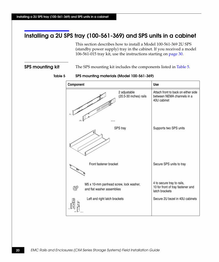
SPS mounting kit The SPS mounting kit includes the components listed in Table 5.
Table 5 SPS mounting materials (Model 100-561-369)
Component Use
2 adjustable (20.5-30 inches) rails
Attach front to back on either side between NEMA channels in a 40U cabinet
SPS tray Supports two SPS units
Front fastener bracket Secure SPS units to tray
M5 x 10-mm panhead screw, lock washer,and flat washer assemblies
4 to secure tray to rails, 10 for front of tray fastener and latch brackets
Left and right latch brackets Secure 2U bezel in 40U cabinets
(L)
(R) EMC3456
(L)
(R) EMC3472
EMC Rails and Enclosures (CX4 Series Storage Systems) Field Installation Guide 21
Installing a 2U SPS tray (100-561-369) and SPS units in a cabinet
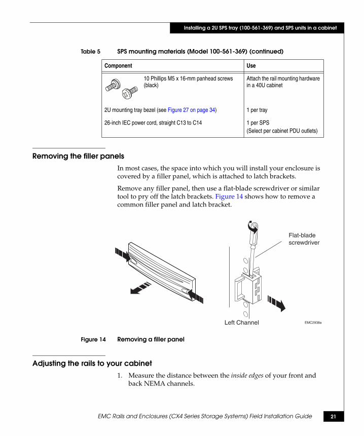
Removing the filler panelsIn most cases, the space into which you will install your enclosure is covered by a filler panel, which is attached to latch brackets.
Remove any filler panel, then use a flat-blade screwdriver or similar tool to pry off the latch brackets. Figure 14 shows how to remove a common filler panel and latch bracket.
Figure 14 Removing a filler panel
Adjusting the rails to your cabinet1. Measure the distance between the inside edges of your front and
back NEMA channels.
10 Phillips M5 x 16-mm panhead screws (black)
Attach the rail mounting hardware in a 40U cabinet
2U mounting tray bezel (see Figure 27 on page 34) 1 per tray
26-inch IEC power cord, straight C13 to C14 1 per SPS(Select per cabinet PDU outlets)
Table 5 SPS mounting materials (Model 100-561-369) (continued)
Component Use
EMC2938aLeft Channel
Flat-blade screwdriver

22 EMC Rails and Enclosures (CX4 Series Storage Systems) Field Installation Guide
Installing a 2U SPS tray (100-561-369) and SPS units in a cabinet
2. Remove the adjustment screws from your rails (if necessary) and extend the rails to the proper length.
3. Secure the 4 adjustment screws at the furthest outside positions possible, as shown in Figure 15.
Figure 15 Adjusting 2U SPS rail length
Installing the rails in the cabinetThis section describes how to mount the rails in the cabinet.
1. After you adjust the rails and decide where in the cabinet you want to install the SPS tray, find the unoccupied 2U section on the rear channels. We suggest that you install the SPS tray immediately below the SPE2, if possible (refer to the device placement examples beginning on page 3).
2. From the front of the cabinet, insert the alignment pins on one mounting rail assembly into the appropriate holes of the selected 2U space on a rear channel. Figure 16 shows the correct channel holes for the alignment pins.
Adjustmentscrews
Adjustmentscrews
Adjustmentscrews
Adjustmentscrews
SPS adjustable rails EMC3460

EMC Rails and Enclosures (CX4 Series Storage Systems) Field Installation Guide 23
Installing a 2U SPS tray (100-561-369) and SPS units in a cabinet
Figure 16 2U pin alignment
3. Extend the rail to the front cabinet channel. Align the holes of the front rail flange to the inside of the channel, ensure that the rail is level, and then install an M5 x 16-mm Phillips securing screw in the center hole, as shown in Figure 17.
Figure 17 Installing the 2U SPS adjustable rails
2U
Alignment pinshere
EMC3479
EMC3461
SPS adjustable rail
Right rear
Screw (2)
Alignment pin (2)
Mounting rail
Right front
Mounting rail
Screw (1)
24 EMC Rails and Enclosures (CX4 Series Storage Systems) Field Installation Guide
Installing a 2U SPS tray (100-561-369) and SPS units in a cabinet
Note: Leave the screw slightly loose to allow for adjustment after you install the tray.
4. At the back of the cabinet, insert and tighten two M5 x16-mm securing screws in the holes above and below the alignment pins, as shown in Figure 17.
5. Repeat steps 2 through 4 for the other rail assembly.
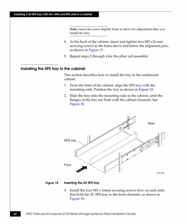
Installing the SPS tray in the cabinetThis section describes how to install the tray in the rackmount cabinet.
1. From the front of the cabinet, align the SPS tray with the mounting rails. Position the tray as shown in Figure 18.
2. Slide the tray onto the mounting rails in the cabinet, until the flanges of the tray are flush with the cabinet channels. See Figure 18.
Figure 18 Inserting the 2U SPS tray
3. Install the four M5 x 16mm securing screws (two on each side) that hold the 2U SPS tray to the front channels, as shown in Figure 19.
Rear
Front
EMC3462
SPS tray

EMC Rails and Enclosures (CX4 Series Storage Systems) Field Installation Guide 25
Installing a 2U SPS tray (100-561-369) and SPS units in a cabinet
Figure 19 Securing the 2U SPS tray in the cabinet
4. Install the four M5 x 10mm securing screws (two on each side) that hold the rear of the 2U SPS tray to the mounting rails, as shown in Figure 19.
You have installed an SPS tray. Continue to the next section to install the SPS units.
Rear
Front
EMC3463
Screws (2)each side
Screws (2)each side

26 EMC Rails and Enclosures (CX4 Series Storage Systems) Field Installation Guide
Installing a 2U SPS tray (100-561-369) and SPS units in a cabinet
Installing the SPS units in a 2U tray
WARNING
The unit is heavy and should be installed into a rack by two people. To avoid personal injury and/or damage to the equipment, do not attempt to lift and install the unit into a rack without a mechanical lift and/or help from another person.
L’armoire étant lourde, sa mise en place sur une rampe nécessite deux personnes. Afin de ne pas vous blesser et/ou endommager le matériel, n’essayez pas de soulever et d’installer l’armoire sur une rampe sans avoir recours à un relevage mécanique et/ou à l’aide d’une autre personne.
Das Gehäuse ist schwer und sollte nur von zwei Personen in einem Rack installiert werden. Zur Vermeidung von körperlichen Verletzungen und/oder der Beschädigung des Gerätes, bitte das Gehäuse nicht ohne die Hilfe einer zweiten Person anheben und einbauen.
Il contenitore è pesante e dev'essere installato nel rack da due persone. Per evitare danni personali e/o all’apparecchiatura, non tentare di sollevare ed installare in un rack il contenitore senza un sollevatore meccanico e/o l’aiuto di un’altra persona.
Debido a su considerable peso, la instalación del compartimento en el bastidor deben realizarla siempre dos personas. Para evitar daños personales o en el equipo, el compartimento no debe levantarse ni instalarse en el bastidor sin la ayuda de un elevador mecánico o de otra persona.
1. Remove the SPS units from their packaging.
Working from the front of the cabinet, and with help from another person or mechanical lift, slide the SPS units onto the tray as shown in Figure 20.

EMC Rails and Enclosures (CX4 Series Storage Systems) Field Installation Guide 27
Installing a 2U SPS tray (100-561-369) and SPS units in a cabinet
Figure 20 Inserting SPS units into the 2U tray
2. Attach the front fastening bracket, and insert and tighten the eight M4 x 10-mm panhead securing screws as shown in Figure 21.
Figure 21 Installing the 2U SPS front fastening bracket
Rear
Front
EMC3467
Rear
Front
EMC3469
SPS fastening bracket
Screw (8)to SPSs

28 EMC Rails and Enclosures (CX4 Series Storage Systems) Field Installation Guide
Installing a 2U SPS tray (100-561-369) and SPS units in a cabinet
3. Tighten the four captive thumbscrews (shown in Figure 22) that secure the SPS units to the back of the tray.
Figure 22 Securing the 2U SPS rear
Installing latch brackets and bezelThis section describes how to install latch brackets and the bezel they support.
1. Use four Phillips M4 x 10-mm screws to secure latch brackets on each side of the front fastening bracket. (The brackets are stamped L and R for correct orientation.) See Figure 23.
2. Press the bezel onto the latch brackets until it snaps into place.
Figure 23 installing the latch bracket and bezel
You have installed an SPS tray and SPS units in the cabinet.
EMC3480Captive thumbscrews
CL4219

EMC Rails and Enclosures (CX4 Series Storage Systems) Field Installation Guide 29
Installing a 2U SPS tray (100-561-369) and SPS units in a cabinet
3. If you are installing another device in the cabinet, continue with the appropriate instructions. For example, to add a storage processor enclosure above the SPS you just installed, refer to “Installing a 4U storage processor enclosure (SPE) in a cabinet” on page 40.
Next, cable the enclosures and SPS units as described in the appropriate setup guide.
30 EMC Rails and Enclosures (CX4 Series Storage Systems) Field Installation Guide
Installing a 2U SPS tray (106-561-015) and SPS units in a cabinet
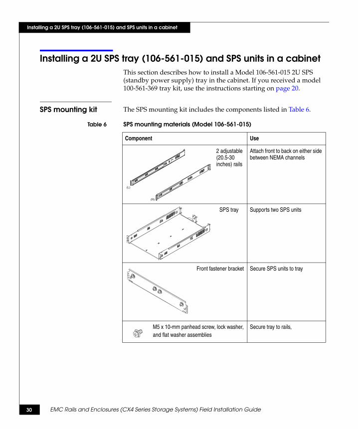
Installing a 2U SPS tray (106-561-015) and SPS units in a cabinetThis section describes how to install a Model 106-561-015 2U SPS (standby power supply) tray in the cabinet. If you received a model 100-561-369 tray kit, use the instructions starting on page 20.
SPS mounting kit The SPS mounting kit includes the components listed in Table 6.
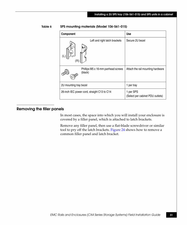
Table 6 SPS mounting materials (Model 106-561-015)
Component Use
2 adjustable (20.5-30 inches) rails
Attach front to back on either side between NEMA channels
SPS tray Supports two SPS units
Front fastener bracket Secure SPS units to tray
M5 x 10-mm panhead screw, lock washer,and flat washer assemblies
Secure tray to rails,
CL4098(L)
(R)
CL4097
CL4083
EMC Rails and Enclosures (CX4 Series Storage Systems) Field Installation Guide 31
Installing a 2U SPS tray (106-561-015) and SPS units in a cabinet
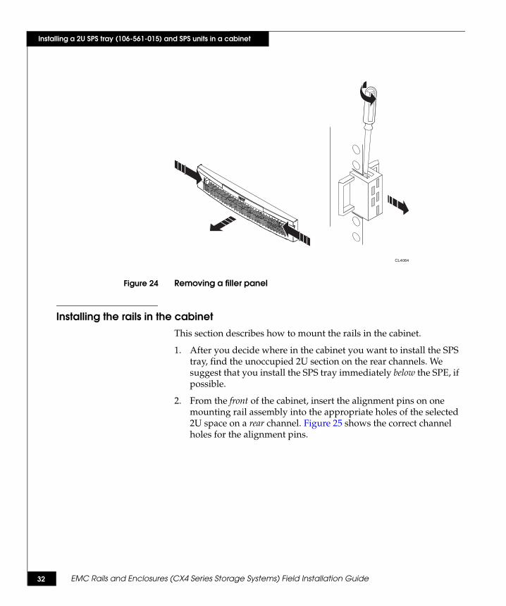
Removing the filler panelsIn most cases, the space into which you will install your enclosure is covered by a filler panel, which is attached to latch brackets.
Remove any filler panel, then use a flat-blade screwdriver or similar tool to pry off the latch brackets. Figure 24 shows how to remove a common filler panel and latch bracket.
Left and right latch brackets Secure 2U bezel
Phillips M5 x 16-mm panhead screws (black)
Attach the rail mounting hardware
2U mounting tray bezel 1 per tray
26-inch IEC power cord, straight C13 to C14 1 per SPS(Select per cabinet PDU outlets)
Table 6 SPS mounting materials (Model 106-561-015)
Component Use
(L)
(R)CL4144
32 EMC Rails and Enclosures (CX4 Series Storage Systems) Field Installation Guide
Installing a 2U SPS tray (106-561-015) and SPS units in a cabinet
Figure 24 Removing a filler panel
Installing the rails in the cabinetThis section describes how to mount the rails in the cabinet.
1. After you decide where in the cabinet you want to install the SPS tray, find the unoccupied 2U section on the rear channels. We suggest that you install the SPS tray immediately below the SPE, if possible.
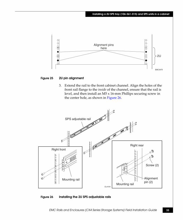
2. From the front of the cabinet, insert the alignment pins on one mounting rail assembly into the appropriate holes of the selected 2U space on a rear channel. Figure 25 shows the correct channel holes for the alignment pins.
CL4064
EMC Rails and Enclosures (CX4 Series Storage Systems) Field Installation Guide 33
Installing a 2U SPS tray (106-561-015) and SPS units in a cabinet
Figure 25 2U pin alignment
3. Extend the rail to the front cabinet channel. Align the holes of the front rail flange to the inside of the channel, ensure that the rail is level, and then install an M5 x 16-mm Phillips securing screw in the center hole, as shown in Figure 26.
Figure 26 Installing the 2U SPS adjustable rails
2U
Alignment pinshere
EMC3479
CL4104
SPS adjustable rail
Right front
Mounting rail
Right rear
Screw (2)
Mounting rail
Alignment pin (2)

34 EMC Rails and Enclosures (CX4 Series Storage Systems) Field Installation Guide
Installing a 2U SPS tray (106-561-015) and SPS units in a cabinet
Note: Leave the screw slightly loose to allow for adjustment after you install the tray.
4. At the back of the cabinet, insert and tighten two M5 x16-mm securing screws in the holes above and below the alignment pins, as shown in Figure 26.
5. Repeat steps 2 through 4 for the other rail assembly.
Installing the SPS tray in the cabinetThis section describes how to install the tray in the rackmount cabinet.
1. From the front of the cabinet, align the SPS tray with the mounting rails. Position the tray as shown in Figure 27.
2. Slide the tray onto the mounting rails in the cabinet, until the flanges of the tray are flush with the cabinet channels. See Figure 27.
Figure 27 Inserting the 2U SPS tray
3. Install the four M5 x 16mm securing screws (two on each side) that hold the 2U SPS tray to the front channels, as shown in Figure 28.
CL4101
Front
Rear

EMC Rails and Enclosures (CX4 Series Storage Systems) Field Installation Guide 35
Installing a 2U SPS tray (106-561-015) and SPS units in a cabinet
Figure 28 Securing the 2U SPS tray in the cabinet
4. Install the two M5 x 10mm securing screws (one on each side) that secure the 2U SPS tray to the mounting rails, as shown in Figure 28.
You have installed an SPS tray. Continue to the next section to install the SPS units.
CL4100
Front
Rear

36 EMC Rails and Enclosures (CX4 Series Storage Systems) Field Installation Guide
Installing a 2U SPS tray (106-561-015) and SPS units in a cabinet
Installing the SPS units in a 2U tray
WARNING
The unit is heavy and should be installed into a rack by two people. To avoid personal injury and/or damage to the equipment, do not attempt to lift and install the unit into a rack without a mechanical lift and/or help from another person.
L’armoire étant lourde, sa mise en place sur une rampe nécessite deux personnes. Afin de ne pas vous blesser et/ou endommager le matériel, n’essayez pas de soulever et d’installer l’armoire sur une rampe sans avoir recours à un relevage mécanique et/ou à l’aide d’une autre personne.
Das Gehäuse ist schwer und sollte nur von zwei Personen in einem Rack installiert werden. Zur Vermeidung von körperlichen Verletzungen und/oder der Beschädigung des Gerätes, bitte das Gehäuse nicht ohne die Hilfe einer zweiten Person anheben und einbauen.
Il contenitore è pesante e dev'essere installato nel rack da due persone. Per evitare danni personali e/o all’apparecchiatura, non tentare di sollevare ed installare in un rack il contenitore senza un sollevatore meccanico e/o l’aiuto di un’altra persona.
Debido a su considerable peso, la instalación del compartimento en el bastidor deben realizarla siempre dos personas. Para evitar daños personales o en el equipo, el compartimento no debe levantarse ni instalarse en el bastidor sin la ayuda de un elevador mecánico o de otra persona.
1. Remove the SPS units from their packaging.
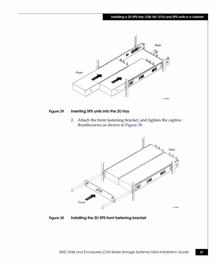
Working from the front of the cabinet, and with help from another person or mechanical lift, slide the SPS units onto the tray as shown in Figure 29.
EMC Rails and Enclosures (CX4 Series Storage Systems) Field Installation Guide 37
Installing a 2U SPS tray (106-561-015) and SPS units in a cabinet
Figure 29 Inserting SPS units into the 2U tray
2. Attach the front fastening bracket, and tighten the captive thumbscrews as shown in Figure 30.
Figure 30 Installing the 2U SPS front fastening bracket
CL4099
Front
Rear
Rear
Front
CL4085

38 EMC Rails and Enclosures (CX4 Series Storage Systems) Field Installation Guide
Installing a 2U SPS tray (106-561-015) and SPS units in a cabinet
3. Tighten the eight captive thumbscrews (shown in Figure 31) that secure the SPS units to the back of the tray.
Figure 31 Securing the 2U SPS rear
Installing latch brackets and bezelThis section describes how to install the latch brackets and the bezel they support.
1. Use four Phillips M4 x 10-mm screws to secure latch brackets on each side of the front fastening bracket. (The brackets are stamped L and R for correct orientation.) See Figure 32.
2. Press the bezel onto the latch brackets until it snaps into place.
Figure 32 Installing the latch brackets and bezel
You have installed an SPS tray and SPS units in the cabinet.
CL4102
CL4103
EMC Rails and Enclosures (CX4 Series Storage Systems) Field Installation Guide 39
Installing a 2U SPS tray (106-561-015) and SPS units in a cabinet
If you are installing another device in the cabinet, continue with the appropriate instructions. For example, to add a storage processor enclosure above the SPS you just installed, refer to “Installing a 4U storage processor enclosure (SPE) in a cabinet” on page 40.
Next, cable the enclosures and SPS units as described in the appropriate setup guide.
40 EMC Rails and Enclosures (CX4 Series Storage Systems) Field Installation Guide
Installing a 4U storage processor enclosure (SPE) in a cabinet
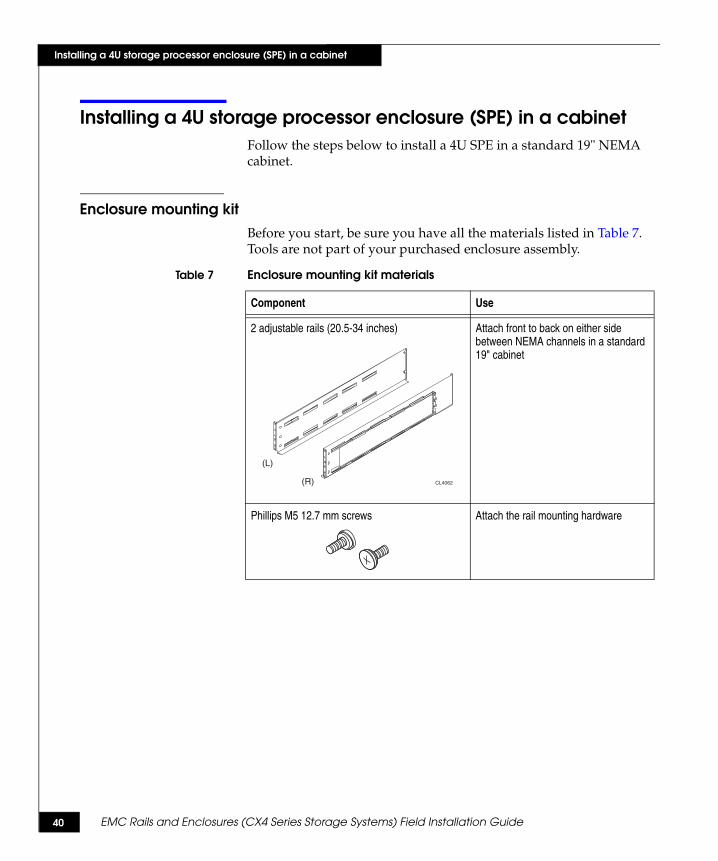
Installing a 4U storage processor enclosure (SPE) in a cabinetFollow the steps below to install a 4U SPE in a standard 19" NEMA cabinet.
Enclosure mounting kitBefore you start, be sure you have all the materials listed in Table 7. Tools are not part of your purchased enclosure assembly.
Table 7 Enclosure mounting kit materials
Component Use
2 adjustable rails (20.5-34 inches) Attach front to back on either side between NEMA channels in a standard 19" cabinet
Phillips M5 12.7 mm screws Attach the rail mounting hardware
(L)
(R) CL4062
EMC Rails and Enclosures (CX4 Series Storage Systems) Field Installation Guide 41
Installing a 4U storage processor enclosure (SPE) in a cabinet
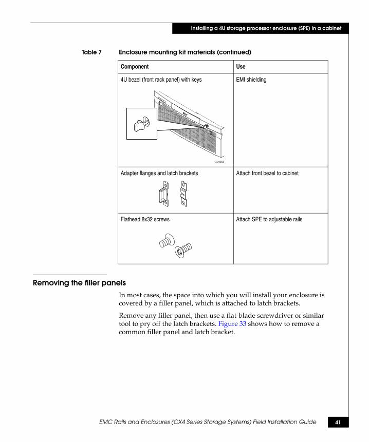
Removing the filler panelsIn most cases, the space into which you will install your enclosure is covered by a filler panel, which is attached to latch brackets.
Remove any filler panel, then use a flat-blade screwdriver or similar tool to pry off the latch brackets. Figure 33 shows how to remove a common filler panel and latch bracket.
4U bezel (front rack panel) with keys EMI shielding
Adapter flanges and latch brackets Attach front bezel to cabinet
Flathead 8x32 screws Attach SPE to adjustable rails
Table 7 Enclosure mounting kit materials (continued)
Component Use
CL4065
42 EMC Rails and Enclosures (CX4 Series Storage Systems) Field Installation Guide
Installing a 4U storage processor enclosure (SPE) in a cabinet
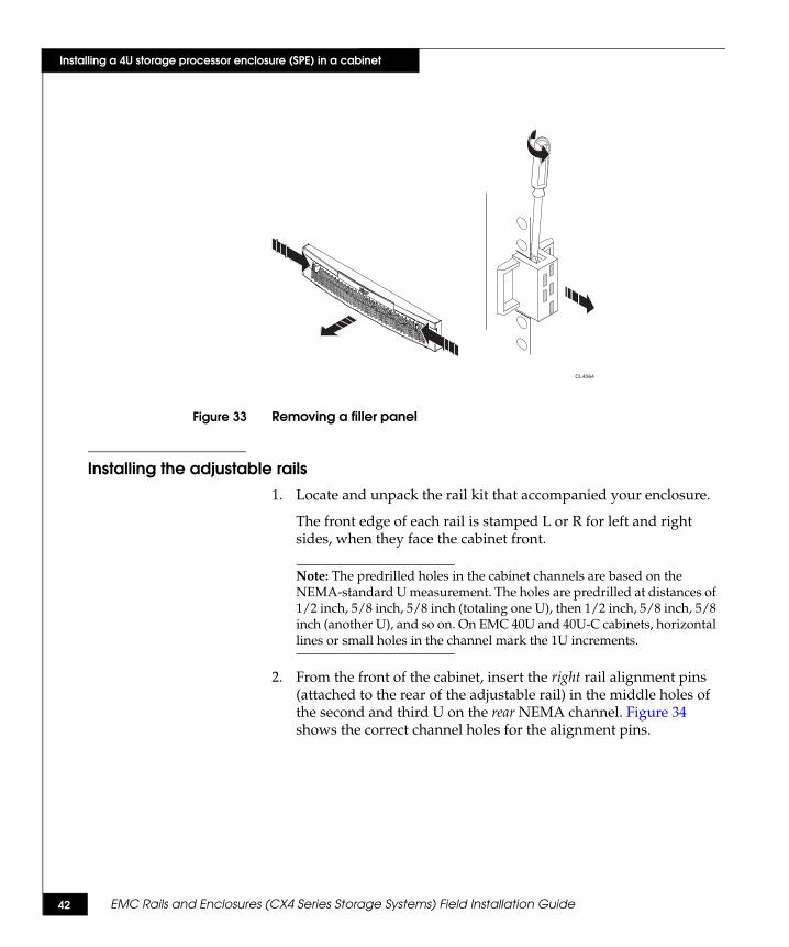
Figure 33 Removing a filler panel
Installing the adjustable rails1. Locate and unpack the rail kit that accompanied your enclosure.
The front edge of each rail is stamped L or R for left and right sides, when they face the cabinet front.
Note: The predrilled holes in the cabinet channels are based on the NEMA-standard U measurement. The holes are predrilled at distances of 1/2 inch, 5/8 inch, 5/8 inch (totaling one U), then 1/2 inch, 5/8 inch, 5/8 inch (another U), and so on. On EMC 40U and 40U-C cabinets, horizontal lines or small holes in the channel mark the 1U increments.
2. From the front of the cabinet, insert the right rail alignment pins (attached to the rear of the adjustable rail) in the middle holes of the second and third U on the rear NEMA channel. Figure 34 shows the correct channel holes for the alignment pins.
CL4064
EMC Rails and Enclosures (CX4 Series Storage Systems) Field Installation Guide 43
Installing a 4U storage processor enclosure (SPE) in a cabinet
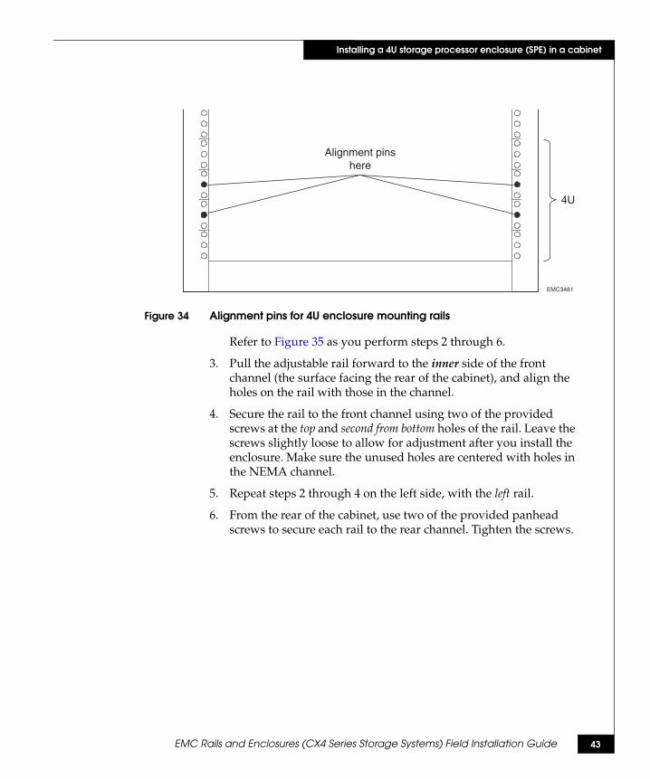
Figure 34 Alignment pins for 4U enclosure mounting rails
Refer to Figure 35 as you perform steps 2 through 6.
3. Pull the adjustable rail forward to the inner side of the front channel (the surface facing the rear of the cabinet), and align the holes on the rail with those in the channel.
4. Secure the rail to the front channel using two of the provided screws at the top and second from bottom holes of the rail. Leave the screws slightly loose to allow for adjustment after you install the enclosure. Make sure the unused holes are centered with holes in the NEMA channel.
5. Repeat steps 2 through 4 on the left side, with the left rail.
6. From the rear of the cabinet, use two of the provided panhead screws to secure each rail to the rear channel. Tighten the screws.
EMC3481
4U
Alignment pinshere

44 EMC Rails and Enclosures (CX4 Series Storage Systems) Field Installation Guide
Installing a 4U storage processor enclosure (SPE) in a cabinet
Figure 35 Installing adjustable mounting rails for a 4U enclosure
CL4071
Right rear
Screw (2)
Alignment pin (2)
Mounting rail
Alignment pins
Adjustable rail
Right front
Screw (2)
Mounting rail

EMC Rails and Enclosures (CX4 Series Storage Systems) Field Installation Guide 45
Installing a 4U storage processor enclosure (SPE) in a cabinet
Installing the enclosure on the rails in the cabinet
WARNING
The enclosure is heavy and should be installed into a rack by two people. To avoid personal injury and/or damage to the equipment, do not attempt to lift and install the enclosure into a rack without a mechanical lift and/or help from another person.
L’armoire étant lourde, sa mise en place sur une rampe nécessite deux personnes. Afin de ne pas vous blesser et/ou endommager le matériel, n’essayez pas de soulever et d’installer l’armoire sur une rampe sans avoir recours à un relevage mécanique et/ou à l’aide d’une autre personne.
Das Gehäuse ist schwer und sollte nur von zwei Personen in einem Rack installiert werden. Zur Vermeidung von körperlichen Verletzungen und/oder der Beschädigung des Gerätes, bitte das Gehäuse nicht ohne die Hilfe einer zweiten Person anheben und einbauen.
Il contenitore è pesante e dev'essere installato nel rack da due persone. Per evitare danni personali e/o all’apparecchiatura, non tentare di sollevare ed installare in un rack il contenitore senza un sollevatore meccanico e/o l’aiuto di un’altra persona.
Debido a su considerable peso, la instalación del compartimento en el bastidor deben realizarla siempre dos personas. Para evitar daños personales o en el equipo, el compartimento no debe levantarse ni instalarse en el bastidor sin la ayuda de un elevador mecánico o de otra persona.
Follow these steps to install the enclosure on the rails in the cabinet:
1. With help from another person, lift the enclosure and, from the front of the cabinet, slide the enclosure onto the rails as shown in Figure 36.

46 EMC Rails and Enclosures (CX4 Series Storage Systems) Field Installation Guide
Installing a 4U storage processor enclosure (SPE) in a cabinet
Figure 36 Sliding a 4U enclosure onto the mounting rails
When the enclosure slides to the back of the cabinet, the two notches in the rear of the enclosure insert into the rear tabs on the back corner of each rail. The tabs secure and support the rear of the enclosure.
Note: If the chassis does not slide all the way into the cabinet, you may need to loosen the screws that hold the rear of the rails in place, then adjust the rails to allow the tabs to fit into the notches.
2. Loosen the captive screws on the power supply to unlock the handle. Extend the power supply handle to install three (3) 8x32 flathead screws to each side of the SPE. These screws secure the SPE to the adjustable rails. Refer to Figure 37.
Repeat for the other side.
CL4073
Front
!
!

EMC Rails and Enclosures (CX4 Series Storage Systems) Field Installation Guide 47
Installing a 4U storage processor enclosure (SPE) in a cabinet
Figure 37 Securing the 4U enclosure to the front NEMA rails
3. Close the power supply handles and secure them in place by tightening the captive screws.
4. Tighten the four screws (two on each rail) that secure the rails to the front channels.
5. Assemble the latch brackets. See Figure 38.
Figure 38 Assembling the latch brackets
CL4075
Front
!
!
!
CL4070

48 EMC Rails and Enclosures (CX4 Series Storage Systems) Field Installation Guide
Installing a 4U storage processor enclosure (SPE) in a cabinet
6. Attach the latch bracket assemblies to the NEMA rails. See Figure 39.
Figure 39 Attaching the latch bracket assemblies
7. Press the front bezel onto the latch brackets at the front of the cabinet until it snaps into place, then lock the bezel with the key. See Figure 40.
Figure 40 Attaching the 4U front bezel
!
CL4072
CL4074
!
!

EMC Rails and Enclosures (CX4 Series Storage Systems) Field Installation Guide 49
Installing a 4U storage processor enclosure (SPE) in a cabinet
8. If you are installing another device in the cabinet, continue with the appropriate instructions. For example, to add a disk array enclosure above the SPE you just installed, refer to “Installing a 3U disk enclosure (DAE) in a cabinet” on page 50.
Next, cable the enclosures and SPS units as described in the appropriate setup guide.
50 EMC Rails and Enclosures (CX4 Series Storage Systems) Field Installation Guide
Installing a 3U disk enclosure (DAE) in a cabinet
Installing a 3U disk enclosure (DAE) in a cabinetFollow the steps below to install a 3U DAE disk enclosure in a standard 19" NEMA cabinet.
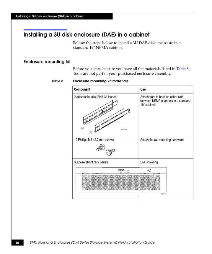
Enclosure mounting kitBefore you start, be sure you have all the materials listed in Table 8. Tools are not part of your purchased enclosure assembly.
Table 8 Enclosure mounting kit materials
Component Use
2 adjustable rails (20.5-34 inches) Attach front to back on either side between NEMA channels in a standard 19" cabinet
12 Phillips M5 12.7 mm screws Attach the rail mounting hardware
3U bezel (front rack panel) EMI shielding
(L)
(R)
EMC3248
CL4141
2Gb4Gb

EMC Rails and Enclosures (CX4 Series Storage Systems) Field Installation Guide 51
Installing a 3U disk enclosure (DAE) in a cabinet
Installing the adjustable rails1. Locate and unpack the rail kit that accompanied your enclosure.
The front edge of each rail is stamped L or R for left and right sides, when they face the cabinet front.
2. In most cases, the space into which you will install your enclosure is covered by a filler panel, which is attached to latch brackets.
Remove any filler panel; then use a flat-blade screwdriver or similar tool to pry off the latch brackets. Figure 41 shows how to remove a common filler panel and latch bracket.
Figure 41 Removing the filler panel and latch bracket
Note: The predrilled holes in the cabinet channels are based on the NEMA-standard U measurement. The holes are predrilled at distances of 1/2 inch, 5/8 inch, 5/8 inch (totaling one U), then 1/2 inch, 5/8 inch, 5/8 inch (another U), and so on. On EMC 40U and 40U-C cabinets, horizontal lines or small holes in the channel mark the 1U increments.
Refer to Figure 42 on page 52 as you perform steps 3 through 7.
3. From the front of the cabinet, insert the right rail alignment pins above and below the bottom U mark on the rear NEMA channel.
CL4064
52 EMC Rails and Enclosures (CX4 Series Storage Systems) Field Installation Guide
Installing a 3U disk enclosure (DAE) in a cabinet
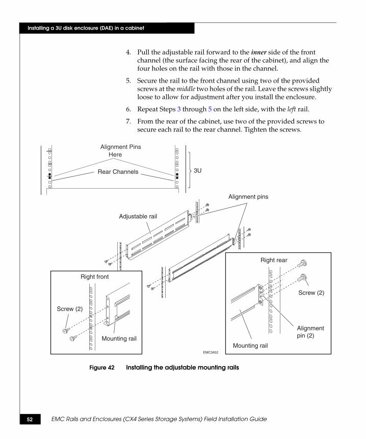
4. Pull the adjustable rail forward to the inner side of the front channel (the surface facing the rear of the cabinet), and align the four holes on the rail with those in the channel.
5. Secure the rail to the front channel using two of the provided screws at the middle two holes of the rail. Leave the screws slightly loose to allow for adjustment after you install the enclosure.
6. Repeat Steps 3 through 5 on the left side, with the left rail.
7. From the rear of the cabinet, use two of the provided screws to secure each rail to the rear channel. Tighten the screws.
Figure 42 Installing the adjustable mounting rails
Alignment PinsHere
EMC2892a
3URear Channels
EMC3452
Right rear
Screw (2)
Alignment pin (2)
Mounting rail
Alignment pins
Adjustable rail
Right front
Mounting rail
Screw (2)
EMC Rails and Enclosures (CX4 Series Storage Systems) Field Installation Guide 53
Installing a 3U disk enclosure (DAE) in a cabinet
Installing a DAE enclosure in the cabinet
WARNING
The enclosure is heavy and should be installed into a rack by two people. To avoid personal injury and/or damage to the equipment, do not attempt to lift and install the enclosure into a rack without a mechanical lift and/or help from another person.
L’armoire étant lourde, sa mise en place sur une rampe nécessite deux personnes. Afin de ne pas vous blesser et/ou endommager le matériel, n’essayez pas de soulever et d’installer l’armoire sur une rampe sans avoir recours à un relevage mécanique et/ou à l’aide d’une autre personne.
Das Gehäuse ist schwer und sollte nur von zwei Personen in einem Rack installiert werden. Zur Vermeidung von körperlichen Verletzungen und/oder der Beschädigung des Gerätes, bitte das Gehäuse nicht ohne die Hilfe einer zweiten Person anheben und einbauen.
Il contenitore è pesante e dev'essere installato nel rack da due persone. Per evitare danni personali e/o all’apparecchiatura, non tentare di sollevare ed installare in un rack il contenitore senza un sollevatore meccanico e/o l’aiuto di un’altra persona.
Debido a su considerable peso, la instalación del compartimento en el bastidor deben realizarla siempre dos personas. Para evitar daños personales o en el equipo, el compartimento no debe levantarse ni instalarse en el bastidor sin la ayuda de un elevador mecánico o de otra persona.
CAUTION!Without proper equipment and procedures, you risk damaging disk drives any time you remove, store, or install them. Do not remove disks prior to installing the chassis.
54 EMC Rails and Enclosures (CX4 Series Storage Systems) Field Installation Guide
Installing a 3U disk enclosure (DAE) in a cabinet
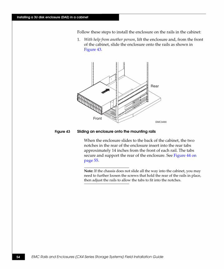
Follow these steps to install the enclosure on the rails in the cabinet:
1. With help from another person, lift the enclosure and, from the front of the cabinet, slide the enclosure onto the rails as shown in Figure 43.
Figure 43 Sliding an enclosure onto the mounting rails
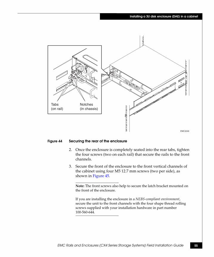
When the enclosure slides to the back of the cabinet, the two notches in the rear of the enclosure insert into the rear tabs approximately 14 inches from the front of each rail. The tabs secure and support the rear of the enclosure. See Figure 44 on page 55.
Note: If the chassis does not slide all the way into the cabinet, you may need to further loosen the screws that hold the rear of the rails in place, then adjust the rails to allow the tabs to fit into the notches.
EMC3490
Rear
Front
EMC Rails and Enclosures (CX4 Series Storage Systems) Field Installation Guide 55
Installing a 3U disk enclosure (DAE) in a cabinet
Figure 44 Securing the rear of the enclosure
2. Once the enclosure is completely seated into the rear tabs, tighten the four screws (two on each rail) that secure the rails to the front channels.
3. Secure the front of the enclosure to the front vertical channels of the cabinet using four M5 12.7 mm screws (two per side), as shown in Figure 45.
Note: The front screws also help to secure the latch bracket mounted on the front of the enclosure.
If you are installing the enclosure in a NEBS-compliant environment, secure the unit to the front channels with the four shape thread rolling screws supplied with your installation hardware in part number 100-560-644.
!!
!!
!
EXP
PRIEXP
PRI
#
!
EXP
PRI EXP
PRI
#
A
B
Tabs(on rail)
Notches(in chassis)
EMC3249

56 EMC Rails and Enclosures (CX4 Series Storage Systems) Field Installation Guide
Installing a 3U disk enclosure (DAE) in a cabinet
Figure 45 Securing the enclosure to the channels
4. Make certain disk drives or filler panels are installed in every disk enclosure slot.
5. Press the front bezel onto the latch brackets at the front of the cabinet until it snaps into place, then lock the bezel with the key. See Figure 46.
Figure 46 Attaching the enclosure front bezel
6. If you are installing another device in the cabinet, continue with the appropriate instructions.
Next, cable the enclosure and any SPS units as described in the appropriate hardware reference manual.
EMC3491Screw (2)
Screw (2)
Rear
Front
EMC3457
Bezellatchbracket
Bezellatchbracket
EMC Rails and Enclosures (CX4 Series Storage Systems) Field Installation Guide 57
Installing front filler panels
Installing front filler panels1U, 2U, and 4U filler panels fill gaps in the NEMA rack. The latch bracket will secure any filler panel to the cabinet. The size of the filler panel determines the orientation of the latch bracket on the front channel.
This section shows you how to install the latch brackets and filler panels in empty spaces in the front of the cabinet.
◆ To install latch brackets for a 1U or 2U space, go to the next section.
◆ To install latch brackets for a 3U space, go to page 59.
◆ After you install the latch brackets, go to page 60 for instructions on installing the filler panel.
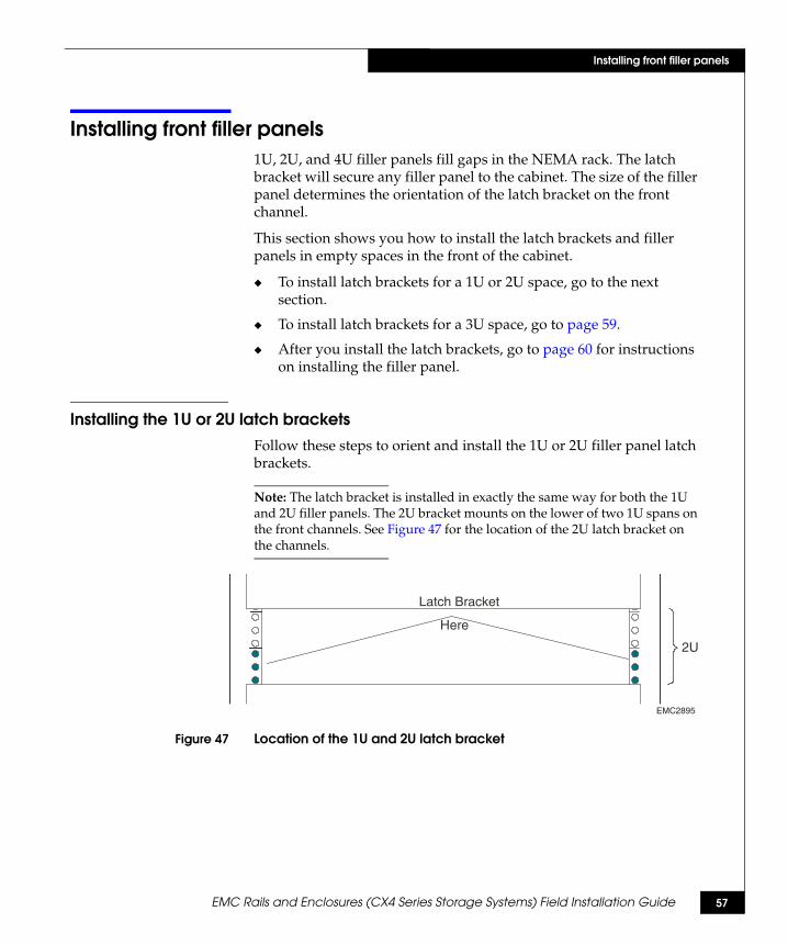
Installing the 1U or 2U latch brackets Follow these steps to orient and install the 1U or 2U filler panel latch brackets.
Note: The latch bracket is installed in exactly the same way for both the 1U and 2U filler panels. The 2U bracket mounts on the lower of two 1U spans on the front channels. See Figure 47 for the location of the 2U latch bracket on the channels.
Figure 47 Location of the 1U and 2U latch bracket
2U
Latch Bracket
Here
EMC2895

58 EMC Rails and Enclosures (CX4 Series Storage Systems) Field Installation Guide
Installing front filler panels
Refer to Figure 48 as you perform steps 1 through 3.1. Facing the cabinet, at the left front channel, align the latch bracket
so that the three holes on the latch bracket are to the front of the cabinet.
2. Align the slot closest to you over the edge of the front channel. Align the top and bottom edge of the latch bracket with the corresponding 1U or 2U notches on the front channel.
3. Push the latch bracket onto the front channel until it locks into place.
Figure 48 Installing the 1U or 2U latch bracket on the left channel
Refer to Figure 49 as you perform steps 4 through 6.
4. At the right front channel, rotate the latch bracket so that the three holes in the latch bracket are to the front of the cabinet.
5. Align the slot closest to you over the edge of the front channel. Align the top and bottom edges of the latch bracket with the top and bottom 1U or 2U notches on the front channel.
6. Push the latch bracket onto the front channel until it locks into place.
Figure 49 Installing the 1U or 2U latch bracket on the right channel
EMC28913 Holes
1UNotches
LeftChannel Bracket in Place
EMC28903 Holes
1UNotches
RightChannel Bracket in Place

EMC Rails and Enclosures (CX4 Series Storage Systems) Field Installation Guide 59
Installing front filler panels
Installing the 3U latch bracketsYou install 3U latch brackets within a 3U span on the front channels. The latch brackets attach at the U mark between the lower 1U spaces, as shown in Figure 50.
Figure 50 Location of the 3U latch bracket
Follow these steps to orient and install the 3U filler panel latch brackets.
Refer to Figure 51 as you perform steps 1 through 3.
1. Facing the cabinet, at the left front channel, align the latch bracket so that the two holes on the latch bracket are to the front of the cabinet.
2. Align the slot closest to you over the edge of the front channel. Align the center of the latch bracket with the lowest 1U mark. See Figure 51.
3. Push the latch bracket onto the front channel until it locks into place.
Figure 51 Installing the 3U latch bracket on the left channel
EMC2889
Latch Bracket
Here
3U
EMC28942 Holes
1UNotch
LeftChannel
Bracket in Place

60 EMC Rails and Enclosures (CX4 Series Storage Systems) Field Installation Guide
Installing front filler panels
Refer to Figure 52 as you perform steps 4 through 6.
4. At the right front channel, rotate the latch bracket so that the two slots in the latch bracket are to the front of the cabinet.
5. Align the slot closest to you over the edge of the front channel. Align the center of the latch bracket with the lowest 1U notch. See Figure 50 on page 59.
6. Push the latch bracket onto the front channel until it locks into place.
Figure 52 Installing the 3U latch bracket on the right channel
Installing the filler panelOnce you have the latch brackets installed on the front rails, you can install the appropriate size filler panel. You will install all of the filler panels on the latch brackets in the same way.
1. Align the vertical slots on the back of the filler panel with the latch bracket.
EMC2893
2 Holes
1UNotches
RightChannel Bracket in Place
EMC Rails and Enclosures (CX4 Series Storage Systems) Field Installation Guide 61
Installing front filler panels
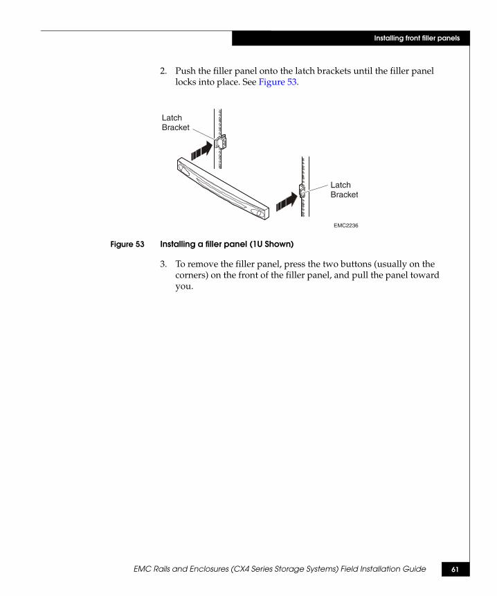
2. Push the filler panel onto the latch brackets until the filler panel locks into place. See Figure 53.
Figure 53 Installing a filler panel (1U Shown)
3. To remove the filler panel, press the two buttons (usually on the corners) on the front of the filler panel, and pull the panel toward you.
EMC2236
LatchBracket
LatchBracket
62 EMC Rails and Enclosures (CX4 Series Storage Systems) Field Installation Guide
Installing front filler panels
Copyright © 2008 EMC Corporation. All rights reserved.
EMC believes the information in this publication is accurate as of its publication date. The information is subject to change without notice.
THE INFORMATION IN THIS PUBLICATION IS PROVIDED “AS IS.” EMC CORPORATION MAKES NO REPRESENTATIONS OR WARRANTIES OF ANY KIND WITH RESPECT TO THE INFORMATION IN THIS PUBLICATION, AND SPECIFICALLY DISCLAIMS IMPLIED WARRANTIES OF MERCHANTABILITY OR FITNESS FOR A PARTICULAR PURPOSE.
Use, copying, and distribution of any EMC software described in this publication requires an applicable software license.
For the most up-to-date regulatory document for your product line, go to the Technical Documentation and Advisories section on EMC Powerlink.
For the most up-to-date listing of EMC product names, see EMC Corporation Trademarks on EMC.com.
All other trademarks used herein are the property of their respective owners.
Related Documents