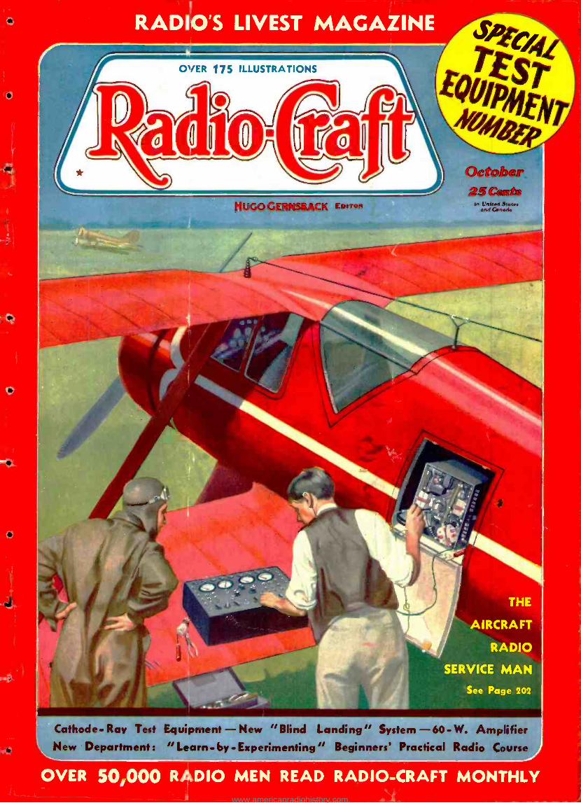
RADIO'S LIVEST MAGAZINE Clete a5Catts /n l bled Jaw. and Canada F,plTilt THE AIRCRAFT RADIO SERVICE MAN See Page 202 Cathode- Ray Test Equipment - New "Blind Landing" System -60- W. Amplifier L_New Department: "Learn - by -Experimenting" Beginners' Practical Radio Course OVER 50,000 R DIO MEN READ RADIO -CRAFT MONTHLY www.americanradiohistory.com

Welcome message from author
This document is posted to help you gain knowledge. Please leave a comment to let me know what you think about it! Share it to your friends and learn new things together.
Transcript
RADIO'S LIVEST MAGAZINE
Clete a5Catts
/n l bled Jaw. and Canada F,plTilt
THE
AIRCRAFT
RADIO
SERVICE MAN
See Page 202
Cathode- Ray Test Equipment - New "Blind Landing" System -60- W. Amplifier L_New Department: "Learn - by -Experimenting" Beginners' Practical Radio Course
OVER 50,000 R DIO MEN READ RADIO -CRAFT MONTHLY www.americanradiohistory.com
I
. e 3 osc°pe OSC\`
voN bo<
Q \ys5995 y O
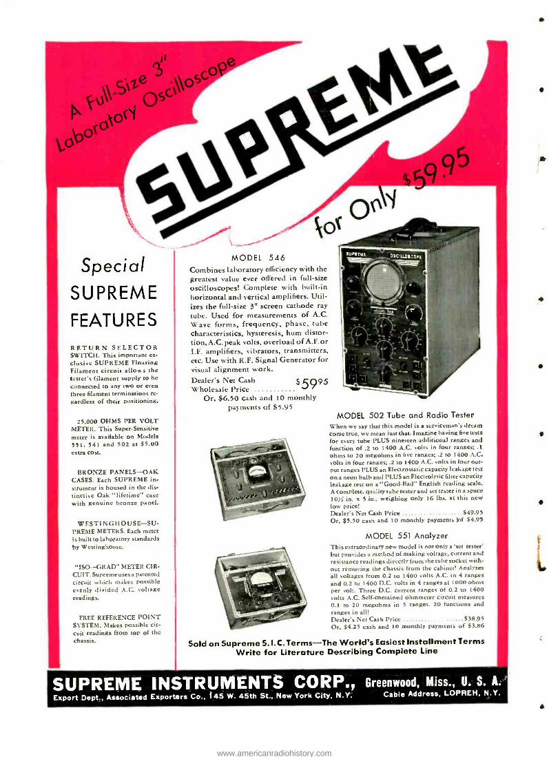
Special SUPREME
FEATURES RETURN SELECTOR SWITCH. This important ex- clusive SUPREME Floating Filament circuit allows the tester's filament supply to be connected to any two or even three filament terminations re- gardless of their positioning.
25.000 OHMS PER VOLT METER. This Super -Sensitive meter is available on Models 551, 541 and 502 at $5.00 extra cost.
BRONZE PANELS -OAK CASES. Each SUPREME in- strument is housed in the dis- tinctive Oak "lifetime" case with genuine bronze paneL
WESTINGHOUSE-SU - PREME METERS. Each meter is built to laboratory standards by Westinghouse.
"ISO -- GRAD" METER CIR- CUIT. Supreme uses a patented circuit which makes possible evenly divided A.C. voltage readings.
FREE REFERENCE POINT SYSTEM. Makes possible cir- cuit readings from top of the chassis.
MODEL 546 Combines laboratory efficiency with the greatest value ever offered in full -size oscilloscopes! Complete with built -in horizontal and vertical amplifiers. Util- izes the full -size 3" screen cathode ray tube. Used for measurements of A.C. Wave forms, frequency, phase, tube characteristics, hysteresis, hum distor- tion,A.C. peak volts, overload of A.F. or I.F. amplifiers, vibrators, transmitters, etc. Use with R.F. Signal Generator for visual alignment work. Dealer's Net Cash $5995 Wholesale Price
Or, $6.50 cash and 10 monthly payments of $5.95
MODEL 502 Tube and Radio Tester When we say that this model is a serviceman's dream come true, we mean just that. Imagine having five tests for every tube PLUS nineteen additional ranges and function of .2 to 1400 A.C. volts in four ranges; .1 ohms to 20 megohms in five ranges; .2 to 1400 A.C. volts in four ranges; .2 to 1400 A.C. volts in four out- put ranges PLUS an Electrostatic capacity leakage test on a neon bulb and PLUS an Electrolytic filter capacity leakage test on "Good -Bad" English reading scale. A complete, quality tube tester and set tester in a space 103; in. x 5 in., weighing only 16 lbs. at this new low price! Dealer's Net Cash Price $49.95 Or, $5.50 cash and 10 monthly payments bf $4.95
MODEL 551 Analyzer This extraordinary new model is not only a 'set tester' but provides a method of making voltage, current and resistance readings directly from the tube socket with- out removing the chassis from the cabinet! Analyzes all voltages from 0.2 to 1400 volts A.C. in 4 ranges and 0.2 to 1400 D.C. volts in 4 ranges at 1000 ohms per volt. Three D.C. current ranges of 0.2 to 1400 volts A.C. Self -contained ohmmeter circuit measures 0.1 to 20 megohms in 5 ranges. 20 functions and ranges in all! Dealer's Net Cash Price $38.95 Or, $4.25 cash and 10 monthly payments of $3.86
Sold on Supreme S.I.C.Terms -The World's Easiest Installment Terms Write for Literature Describing Complete Line
SUPREME INSTRUMENTS CORP., Greenwood, Miss., U. S. A.
Export Dept., Associated Exporters Co., 145 W. 45th St., New York City, N.Y. Cable Address, LOPREH, N.Y.
A
.1/
www.americanradiohistory.com
RADIO -CRAFT for OCTOBER. 1937 193
Haw ¿Jijcrt mom a go Joe THERE'S OJC IN BERLIN THE TENTH FOREIGN STATION TONIGHT. RADIOS
CERTAINLY PUN.
NOT SO GOOD BILL, BUT I'M STILL PLAYING WITH RADIO. HAD DJ C UST NIGHT. IS RADIO STILL YOUR HOBBY TOO?
NO. TOM.IVE BEEN TOO BUSY MAKING GOOD MONEY Our OF RADIO LATELY TO "PLAY WITH IT.
YOURE SURE LUCKY, BILL. I NOTICED YOUR NEW CLOTHES AND SNAPPY CAR. I THOUGHT YOU HAD INHERITED A MILLION.
1'M DOING SWELL IN RADIO. MARY 'AND I ARE TO BE MARRIED NEXT MONTH, RADIO h MORE THAN ,A PLAYTHING. IT'S A WO BUSINESS AND GROWING PAST. TAKE MY YIP AND GET INTO RADIO NOW, TOM!
OH,TOM, ITS WONDERFUL NOW FAST YOU'VE GONE AHEAD IN NAO /O. WE NEVER COULD HAVE GOTTEN MARRIED ON WHAT YOU WERE GETTING BEFORE.
IF BILI SUCCEEDED
I CAN TOO:
THIN I CAN MAKE REAL MONEY SCRs/ICING
,RADIO SETS.
OR INSTALL AM) SERVILI LOUD SPEAKER SYSTOLE
OB GET A JOB IN A
BROADCASTING STATION
OR MAKE 0000 MONEY IN ANY ONE OF THE MANY
OTHER NEW ANO ,GROWING BRAUOKS j F RADIO. fIe °OING
TO SEND FOR THAT FREE BOOK
RIGHT NOW/
OUR WORRIES ARE OVER. I'M MAKING GOOD MONEY NOW, AND THERE'S A FUTURE AHEAD FOR US
IN 4540 /O.
HERE'S PROOF MAKE GOOD' MONEY
$3,500 a Year in Own Business
"After completing the N. R. I. Course I be- came Radio Editor of the Buffalo Courier. Later I started a Radio service business of my own, nd averaged over $3,500 a year. " -T. J. ..í x. TELAAK, 657 Broadway, Buffalo, N. Y.
$10 to $25 a Week in Spare 'Erna
"I am making from $10 to $25 a week in spare time while still holding my regular job as a machinist. I owe my success to N. R. 1. "- WM. F. RUI'P. 203 Front St., Conshohocken. Pa.
GET MY FREE LESSON on Radio Servicing Tips
I n,;l prove that my training 1. praet nal. money-making infonnatbal. that It is easy to understand that it Is just what you need to twister Radio. YIy lesson test, "Radio Re- ceiver Troubles -Their Cause and Bement)" lovers a lung list of Ra- dio receiver troubles in A.C., batten, universal. auto. T. It. F., .autel I.etenslyne, all -ware and other types of sets. A cans reference System gives you rho probable cause and a quirk way to locate and rein - edy them set trouble:. A special section Is devoted to receiver chock.
ip. alignment, balancing. neutral- izing and testing. (let rho lesson Free. No obligation. Just mall comsat.
YOU HAVE THE SAME CHANCE TOM. ABOUT A YEAR AGO ISHOWED YOU A BOOK FROM
NATIONAL RADIO INSTITUTE TELLING ABOUT THE
OPPORTUNITIES ANO FUTURE IN RADIO, AND 110W OTHERS HAD SUC- CEEDED THROUGH THEIR HOME TRAINING, WELL I ENROLLED. ., rí1
YOU CERTA¡ NLY KNOW RADIO. MINE NEVER SOUNDED BETTER
N.R.I TRAINING CERTAINLY PAYS. I JUST STARTED AfEW MONTHS AGO ANO IM ALREADY MAKING
\ GOOD MONEY `rt IN MY SPARE
r j THANKS' ¡` _
TIME.
e . a e (will train you to start a spare time or full time Radio
service business Without Capital
Many Radio Experts Make $30, $50, $75 a Week
EM YOU want to make morn I f I:. I. , 1,
made molly opla,rtultille. cur _, ., IL.r.. Inm , r fu!. lai, Had,.,
Mvire business of your . 'l'ltra =ut of cers,, f,nir hurtle: in the United
ates have Radio sets which regal irly require repairs, . vi,ing, new tubes, etc. Many eta ro old and will s.rm be relitared by new model,. I will train you to sell. install, servies all D'pes of Radio sets -to start your men Radio service business and build it up on utuney made in spare time while learning. Mall coupon for my 64 -page Iwulr. it's FREE.
Gat Ready Now for a Business of Your Own and for Jobs Like These Broadcasting statists employ engineers, operator:. .tat i,m managers and pay te $7,000 Year. Share Ume Radio set servicing pays as numb his $'Pmt t, 37mí a year -full tinte Radier servicing jabs as muni as $30. Val, $ :. a week. Slimy Stade, experts own and operate their own time or part time Radio sales and ,en in. business,,. Stadio manufacturers and Jobber, employ testers, inspectors. foremen. :sunnier:, .sen irTnen, Laying Up to 5';.IIIIO a Sear. Radio operalnrs In ships get gomd pay and . t the world besides. Automobile, t''ii a aviation. rommereial Radio. and loud spealirr ,n s infer good oplrnunitie: n
1. F. Smith, President National Radio Institute
Established 1914
I for the future. Television promise: many Ia.sI Jobs :.nn. Men I trained at h.nm, de ' have good into In all these branches lot Radio, Read their letters in niy 6I -page
uo
Many (Make $5. $10. $15 a Week Extra in Spare Time While LearntnP '' `' Practically every twit:M mbo:xi musts a I' .,.I .pa tome senit-en,:u, . Tile ars.h. .tar yo:. or u I wit mending y,.1 Extra a,xlaaey
spare Si eets. They .ho.v '
4
p you hose to edo Haiti° repair Sob. -how' t. .a.h in qu,rk!.y. Throughout your training I send you Plans and i leas that have ern ,."d Mare time money fur his of renow.. 1 . you apeeial lta,iiu ,nip- .q,
-S'''''<'''. , .nt for em,dueting experiments and building circuits whir¡, ' q4' ,s m ¡unstrap, ¡moon:tot Muth, Prin..mle'_ >b. 'training gh.es y practical Radio experience while learn.ng.
you n. ``lO`1`: Find Out What Radio Offers You -Mail Coupon Now JLpr
.4. o ,
Slail the coupon now far, icy yr.. 1e,...I and ,,,yl honk '' - .$i'*' V 'Rich ltewaNs Ill Radio.' (loth r nee L anyone nv amt ( t »t r iii year. old. My (nook point, , Its 1,:nh,:, tLnre l time R, Y ..sp >' f ul fun time , pimrtu ices, and 1,,.e coning i O .r,..0..\"- Television; shows my Training Ita,lm alai TeI: -ar .1.-.4.- ' vision; tells about my Money a Itacl: Agree:11 et; ,, .,
.haws you letters from men 1 trained. telling . 4eer J
n:hlio they are doing
MAIL, THE COUPON: i what Q`p
u b
,_ Úw ¡n '4,D 6 4y envelope, or paste it on a penny ' ,_,, Q 4G .. 's 5 OC. wv
/.4'.., ,,,f...-4-,0 o°
book. Mail the coupon.
J. E. SMITH. President NATIONAL RADIO INSTITUTE Dept. 7KX, Washington. D. C.
MAI LTHIS Get a Lesson and 64 page book FREE 9CPt o 9y43
O Please Say That You Saw !t in RADIO -CRAFT
4.I ,4
www.americanradiohistory.com
adio- raft Fos The
SERVICE MAN DEALER . RADIOTRICIAN
11111111I I I I I I I I I I I I I I I I I I I I I I I R I I I I I I I I I I I I I I I I I I I I I I I I I I I I I I I I I I I I I I I I I I I I I I I I I I I I I I I I I I I I I I I I I I I I I I I I I I I I I I I I I I I I I I 11 1 1I I I I x I I I I I I I I I I I I11010111
HUGO GERNSBACK, Editor -in -Chief N. H. LESSEM
Associate Editor R. D. WASHBURNE, Managing Editor
1111111111111111111111111111111111111I I I I I I111111111111111111I I I I I I I I I I I I I I I I I rann 111111111111111111 I I I I I I I I I I I I I I I I I 111111/01111 II 1 1 1 1 1 1 11 mra u
C. P. MASON Associate Editor
CONTENTS - OCT. 1937, ISSUE Volume IX Number 4
Editorial: Marconi Hugo Gernsback 197
The Radio Month in Review 198
The "Resonoscope" -New Electronic Device Detects "Off -Key" Notes 200
New "Resolution Tester" for Cathode -Ray Tubes 201
The "Air- Track" System of "Blind Landing" Charles E. Planck 202
The Aircraft -Radio Service Man N. H. Lessem 202
Guglielmo Marconi -1874 -1937 203
New U. S. Coast Guard Aviation Radio 203
New Tubes for the Radio Experimenter -Part II
R. D. Washburne 204 New Set Tester Features Low -Ohm Scale
B. O. Burlingame 205
What Size Oscilloscope? G. M. Buchard 205
Importance of Modern Test Equipment Glenn H. Browning 206
How to Make "The Seafarer" Loop -Type Boat Radio Set -Part II Raymond P. Adams 208
Build This "Optimum- Test" Tube Checker Milton J. Reiner 209
Business -Like "Silent" Servicing J. P. Kennedy 209
Bigger Service Profits from Better Tools! O. J. Morelock 210
New Circuits in Modern Radio Receivers -No. I
F. L. Sprayberry 211
How Dependable Are Your Meter Readings? -Part I
A. A. Ghirardi 212
How to Make a Class AI Push -Pull Negative -Feed- back 60 -W. Amplifier Walter J. Bronson 214
/
Latest in Test Apparatus for the Service Man
"Learn -by- Experimenting" Beginners' Practical Radio Course -Experiment No. I (The "Radio Whistle ")
2 I 6
4"-
Sol D. Prensky 218
ABC of Modern Vibrator Servicing F. E. Wenger 220
The Latest Radio Equipment 221
Modern Servicing Oscilloscopes 222
Business Problems of the Service Man....Jack Grand 223
RADIO SERVICE DATA SHEET:
No. 212 -Crosley Model A -157 (Fiver Roamio) Auto Radio 224
Build This "Intermittent Open" Condenser Tester Joseph Mosio 225
New Instrument Speeds Free -Point Testing G. H. Koch 225
Correct Playback of Spot Recordings -Part I
Ralph L. Power 226
Radio Wittiquiz 226
Operating Notes 227
Servicing Questions and Answers 227
Book Reviews 256
111111 u1111 u nu111111n1110uu111111nu 111010nnm11111111n1111111111111111m 111nnu1111u1111u11nu11nun u10n11111 n1111n11nun
NOVEMBER RADIO- CRAFT- RADIO
VOCATION NUMBER! Facts and figures show that radio facilities are rapidly
being expanded into numerous fields. Radio program
reception and transmission, public address, and electronics
all have been put to new uses. The innumerable money-
making possibilities of these 3 major fields will be evident to the radio man who reads the technical and semi- techni-
cal articles in the forthcoming November issue of RADIO - CRAFT-
-on the newsstands October I.
IIIIIIIII1111111111111111111111111111111111mIII I IIIIIUIIII IRI I I IIIm
Published by Radcraft Publications, Inc. Publication office: 29 Worthington Street, Springfield, Mass. Editorial and Advertising Offices: 99 Hudson Street, New York City. Chicago Advertising Office: L. F. McClure, 919 North Michigan Avenue, Chicago, Ill. Western Advertising Office: Loyd B. Chappell, 530 West Sixth St., Los Angeles, Calif.
Foreign Agents: sondon- Gorringé s American News Agency, 9A Green St., Leicester
Square, W. C. 2, England. Paris -Messageries Dawson, 4 Rue Faubourg, Poissonniers, France. Melbourne -McGill's Agency, 179 Elizabeth St., Australia. Dunedin -James Johnston, Ltd., New Zealand.
RADIO -CRAFT is published monthly, on the first of the month preced- ing that of date: subscription price is $2.50 per year in U. S. and Can- ada. (In foreign countries, $3.00 a year to cover additional postage.) Entered at the post office at Springfield as second -class matter under the act of March 3, 1879.
Text and illustrations of this magazine are copyright and must not be reproduced without permission of the copyright owners.
194
Copyright 1937. Radcraft Publications. Inc.
www.americanradiohistory.com
RADIO -CRAFT for OCTOBER, 1937
MANY OPPORTUNITIES FOR THE
COYNETRAINED---
RADIOMAN
a
195 . ll - ` P4.
are You Ready fora Better Job -More Pay? Don't be an untrained man. Let me show you how to get your start in Radio -a fast growing, live money- making industry.
Prepare for jobs as Assembler, Inspector and Tester -Radio Sales or Service and Installation Work -Broadcasting Station Operator -Wire- less Operator on a Ship or Airplane or Sound Work - HUNDREDS OF OPPORTUNITIES for a real future in radio!
12 Weeks of Shop Training We don't teach by book study. We train you on a great outlay of Radio, Television and Sound equipment -on scores of modern Radio Receivers, actual Broadcasting equipment, Television apparatus and Sound Reproduction equipment, Code and Telegraph equipment, etc. You don't need advanced education or previous experience. We give you - RIGHT HERE IN THE COYNE SHOPS - the actual practice and experience you'll need for your start in this great field. And because we cut out all useless theory and only give that which is necessary you get a practical training in 12 weeks. Mail coupon for all facts about my school and training methods.
TELEVISION andPUBLIC ADDRESS Television is sure to come as a commercial industry. Rapid progress is now being made in developing this new field. It will offer opportunities to the man who is trained in Radio. Here at Coyne you learn Television principles, and work on actual Television equipment. Public Address Systems offer opportunities to the Trained Radio Man. Here is a great new Radio field which is rapidly expanding. Prepare NOW for these wonderful opportunities! Learn Radio Sound Work at COYNE on actual Sound Reproduction equipment. Not a home study course. s
SEND FOR DETAILS OF MY
"PAY AFTER GRADUATION" PLAN Mail the Coupon below and I'll tell you about my "Pay After Graduation" Plan which has enabled hundreds of others to get Coyne training with very little money. On this plan you can get your training first, then take 18 months to complete your small monthly tuition payments starting 5 months after you begin training. Not a home study course.
Mail the coupon for all details of this "Tuition Payment Plan."
PRACTICAL WORK at COYNE in Chicago
ACTUAL, PRACTICAL WORK. You build and service radio sets. You get training on real Broadcasting equipment. You construct Television Receiving Sets and actually transmit your own Tele- vision images over our Television equipment. You work on real Sound equipment. You learn Wireless Operating on Actual Code Practice apparatus. We don't waste time on useless theory. We give you the practical training you'll need for your start in Radio -in 12 short weeks. If you desire code, this requires additional time for which there is no extra charge.
Mail Coupon Today for All the Facts H. C. LEWIS, Pres. RADIO DIVISION Founded 1899
Coyne Electrical School 500 S. Paulina St., Dept. 77 -8H, Chicago, Ill.
ELECTRIC REFRIGERATION AIR CONDITIONING
AUTOMOBILE ELECTRICAL WORK Instruction now included at no extra cost. Here is your opportunity to learn these valuable allied lines without extra tuition charge.
PART TIME EMPLOYMENT TO HELP YOU "EARN WHILE LEARNING"
If you are short of money and need part time employment to help pay for your room and board while training, my Employment Depart- ment will help you get a part time job.
GET THE FACTS Don't let lack of money prevent
A your sending in the Coupon. Mail
a: lli i k `7ÍQ : the Coupon today and I Will send
fyuolu l otf h
Fe ABTFREE Coyne Book
H. C. LEWIS. Pres. I Radio Division, Coyne Electrical School
14rase Sa
1
I I I
City State
500 S. Paulina St., Dept. 77-1H, Chicago, Ill. Dear Mr. Lewis: -Send me your Big Free Radio Book, and all details of your "Pay After Graduation" Plan including valuable instruction in Electric Refrigeration, Air Conditioning and Auto- mobile Electrical Work.
Name
Address
That Ian Saw It in RADIO -CRAFT
www.americanradiohistory.com
196 RADIO -CRAFT for OCTOBER, 1937-
t-e,test ADVANCE SALE EVER GIVEN A RIDER MANUAL
Never has a Rider Manual had the enthusiastic reception which Volume VIII enjoys -even before its publication. Never have the advance orders been so great. This is the result of, FIRST: The tremendous and ever -increasing popu- larity of Rider Manuals. SECOND: Technicians' recogni- tion of the thorough planning which has gone into this latest volume. For, this is NOT just another volume; RATHER it is so complete and so well laid out that it actually represents a great forward stride toward the perfect Manual.
To deliver the same degree of completeness which has characterized other Rider Manuals it was necessary to make Volume VIII over 1600 pages. Think of it, over 1600 pages chock -full of dependable information which will make the radio serviceman's work easier and more profitable -and at no increase over the price of Volume VII f And - in spite of today's rising costs of publishing, each copy of Volume VIII will be supplemented with an additional
invaluable section entitled "How It Works." This separate section meets the current need for special technical infor- mation on the modern radio set -outside as well as whhin the actual radio circuit. Motorized tuning -special auto- matic frequency circuits -these and other mechanical as well as electrical kinks and innovations of the modern set must be understood if the serviceman is to work on the better sets -which pay the bigger profits.
Of course, you need all the preceding volumes of Rider Manuals which cover receivers issued between 1920 and 1937. Check your Rider Manuals with the list below and order any missing volumes when you order your Volume VIII covering the 1937 -1938 models.
go'
Vol. VIII .$10.00 .. . 1937.38 Vol. IV . 7.50... 1933-34 Vol. V11.. 10.00...1936 -37 vol. III 7.50... 1932-33 Vol. VI . 7.50 -.1935.36 Vol. II . 7.50 ... 1931-32 Vol. V .... 7.50 ... 1934.35 Vol. I .. 7.5 0 ... 1920.31
V O L U M E V I I I I N TWO SECTIONS "HOW IT WORKS"
A new "plus" service for Rider Manual user. A separate section which goes with every copy of Volume VIII and describes the Technical Features, both mechanical and electrical, that servicemen must know to repair the modern set with Automatic Frequency Control sys- tems and motorised tuning devices. You will find this section of great value.
MANUAL Volume VIII contains more than 1600 pages of circuit Information en receivers produced by over a hundred different manufacturers. Auto -radio receivers, hore receivers, inter -communicating systems, public address ampliRers, electronic musical instruments, etc., are all covered. As to the completeness of the information and the models represented, we suggest your compering it with any other service now offered. Compare the replacement pans list, the alignment instructions. Compare it for convenience in use, or anything else which would hove a bearing on its value to you.
INDEX Check this easy to follow Indes. See the tremendous umber of sets and models covered Note, too, that this Indes proves what we soy - "that information on every set is Instantly found." A time saver and o convenience for you. This Indes of about 118 pages covers all eight Rider Manuals and goes with every copy of Volume VIII.
JOHN Fe RIDER, Publisher, 1440 BROADWAY, NEW YORK
PLACE YOUR ORDER TODAY N11111/ti
--.
Please Say That You Sato It in RADIO-CRAFT
PLUS A SUPPLEMENTARY BOOK
www.americanradiohistory.com
adio@ff FOR THE
SERVICE MAN. DEALER RADIOTRICIAN
"Takes the Resistance out of Radio " 111111111111111mminnueniimiliumei m memi mmununnumeennmunn minim imeeneen murmur nunuuu mmii oninemelemm ineenenem n ueemmnmemnimonnuxuneemeennenummeem enur Editorial Offices: 99 Hudson St., New York, N. Y. HUGO GERNSBACK, Editor Vol. IX, No. 4, October 1937
: 1111111111111111111111111111111!
MARCONI An Editorial by HUGO GERNSBACK
c::N JULY 20th, there died in Rome, Guglielmo Marconi who may turn out to be the greatest radio figure the world has ever seen.
Marconi . . . wireless . . . radio, all are used synonymously and you cannot very well think of wireless or radio without the accomplishments of that indefatigable genius who was the first to capture the public's imagination by an accomplishment, which in the early years of wireless well nigh bordered on the miraculous. 1 Marconi no doubt will go down in history as one of the race's great benefactors, as great or greater than any other benefactor who ever lived. The debt which the world owes to Marconi is staggering -if you figure only one single result of his accomplishments -the saving of tens of thousands of lives which would have perished in the sea and otherwise, if it had not been for Marconi.
But the saving of untold lives is only one of the things that the world is indebted for to Marconi. The wireless, later the radio age, has brought to life not only a huge industry, but has brought all humans closer together, has made rapid communication, particularly between fixed and mobile stations, a possibility and lately in broadcasting has given the human voice wings such as it never before dreamt of having.
Yet great as Marconi's accomplishments are, he was not the pure inventor type of man, although his name is fre- quently linked with the word "inventor." Without trying to
a detract from Marconi's greatness -there could be nothing further from my mind -Marconi was really not the man who invented wireless or radio. He admitted this freely in his own lectures. The credit for the original invention belongs to Heinrich Hertz, who, long before Marconi, investigated in pure scientific terms the electro- magnetic waves, and indeed to Hertz belongs the honor of being the real Father of Radio.
Hertz it was who in his laboratory actually transmitted and received wireless signals. By means of a spark coil he let loose into free space wireless waves. For a receiver he merely used a small loop of copper wire and observed a small spark which appeared between the two open ends of the loop every time the key of the transmitter was depressed.
o These experiments were made by Hertz while Marconi still was a boy, but, Hertz was a pure physicist and had little imagination. Marconi, reading of Hertz's experiments, promptly started to experiment on his own behalf, and soon he had a wireless transmitter and receiver going on his father's estate in Bologna, Italy. Even Marconi's "coherer" was not his own invention, but Branley's. Others before had noted that loose metallic filings in a glass tube became con- ductive to the electric current when exposed near the wave effect of a spark coil or high -power induction coil.
As for the elevated aerial used by Marconi, this also was not an invention of his own as Nikola Tesla had already patented a wireless system years before the youthful Mar- coni began his own experiments. It was Tesla too, who seems to be the first to show the use of an elevated conductor for inter -communication purposes without wires.
All of this should not detract anymore from the glory of Marconi's accomplishments than the parallel facts that Edi- son was not the original inventor of either the electric light,
motion picture or other inventions usually accredited to him. Neither Marconi nor Edison were pure research men who discovered new principles and used them.
Why then Marconi's greatness? It is one thing to discover an important and record -making discovery, but it is quite another thing to find a practical use for it. The two, as a rule, have little relation, and it is usually the man with th3 imagination, and the hard -working experimenter who, know- ing certain principles, applies them to practical use. If it had not been for Marconi, Hertz's discovery might have lain dormant for decades, but the highly original experiment: and the terrifically hard work coupled with boundless er.- thusiasm which Marconi applied to a well -known principl gave him the credit which rightfully belongs to him.
And let no one think that it was all easy and that wireless communication sprang into life overnight. It was always hard work in the face of an incredulous world. Indeed, after his first experiments in Italy were successful, the Italian government in their shortsightedness would have nothing to do with Marconi's "contraption" as they termed it. This made it necessary for Marconi to go to England and con- tinue his experiments there. Soon his signals had reached across the English channel to France, and from then on wireless communication required no further proofs of its practicability.
But still wireless in those days was very crude and far from universal. In the meanwhile Marconi surrounded him- self with good technical talent; he also knew where to get needed finances, and finally he availed himself of every new invention that came along to make his system more practical. While he devised many radio circuits, he did not himself discover the fundamental tuning principle, yet he improved existing methods of tuning- syntony -as it was then called, and soon it became possible to operate many wireless stations without too much interference from each other.
But Marconi was not content. He never rested on his laurels. He always was a modest worker who gave credit to whom credit was due, and the honors for dreaming about trans -Atlantic wireless and the courage to actually start experimenting with it in the face of an incredulous world, certainly belong to Marconi. It should not be forgotten that it took a tremendous amount of courage and belief in himself to think that a new and untried system of transmitting electromagnetic waves over almost 2,000 miles of curved ocean surface was within the realm of even a remote possibility. That took more than courage. It was really a supreme heroic gesture, and it is probably for this one out- standing accomplishment, more than any other, that the world is paying homage to the dead inventor today.
In his later years, Marconi again was responsible for great improvements in radio communication, particularly in the shortwave range and his final researches in the micro- wave field which hold great promise, were cut short by his untimely death.
Marconi was truly an international figure, and if there is one man who ever trod the earth, who is entitled to have a monument erected in his honor in every civilized country on the globe, that man without a shadow of a doubt is the illustrious Marconi.
197
www.americanradiohistory.com
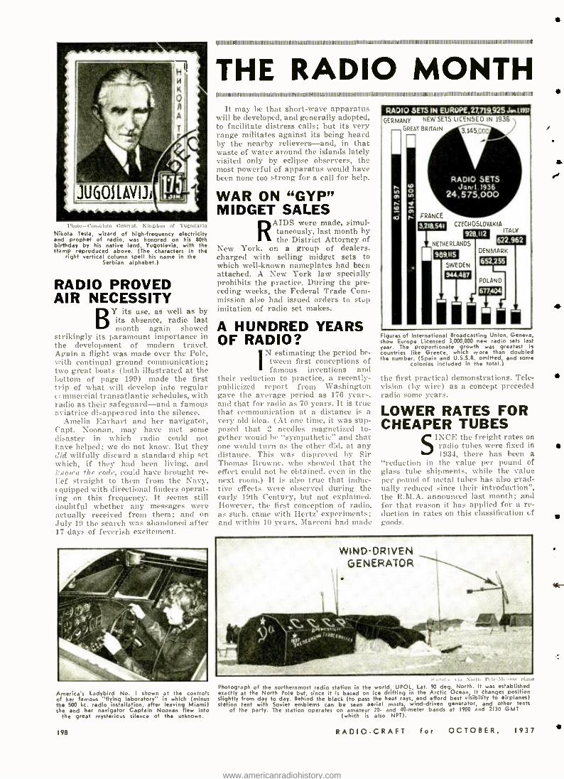
chute-- Comiulate G enel:,l. I, l',., ...
Nikola Tesla, wizard of high -frequency electricity and prophet of radio, was honored on his 80th birthday by his native land, Yugoslavia, with the stamp reproduced above. (The characters in the
right vertical column spell his name in the Serbian alphabet.)
RADIO PROVED AIR NECESSITY
its use, as well as by Y its absence, radio last month again showed
strikingly its paramount importance in the development of modern travel. Again a flight was made over the Pole, with continual ground communication; two great boats (both illustrated at the bottom of page 199) made the first trip of what will develop into regular commercial transatlantic schedules, with radio as their safeguard -and a famous aviatrice disappeared into the silence.
Amelia Earhart and her navigator, Capt. Noonan, may have met some disaster in which radio could not have helped; we do not know. But they did wilfully discard a standard ship set which, if they had been living, and known the code, could have brought re- l:ef straight to them from the Navy, equipped with directional finders operat- ing on this frequency. It seems still doubtful whether any messages were actually received from them; and on July 19 the search was abandoned after 17 days of feverish excitement.
America's Ladybird No. I shown at the controls of her famous "flying laboratory" in which (minus the 500 kc. radio installation, after leaving Miami) she and her navigator Captain Noonan flew into
the great mysterious silence of the unknown.
198
OII1111111111IIIIIIIIIII II11111111111III I I IIIIIIIIII11111111111111111111IIIIIIIIII II IIII1111111111111111111111111IIIII IIIIII I II I IIII I I IIIII I IIIIIIIIIIIIIIIIIIIII III IIIIIIII IIIIIIIIIIIIII111111111111111111
THE RADIO MONTH ! I I I I I I I I I I I I I 1111111 1 1 1 1 111111111 I I I I I I I I I I I I I I I I I I I I I I I I I I 111111
It may be that short -wave apparatus will be developed, and generally adopted, to facilitate distress calls; but its very range militates against its being heard by the nearby relievers -and, in that waste of water around the islands lately visited only by eclipse observers, the
most powerful of apparatus would have been none too strong for a call for help.
WAR ON "GYP" MIDGET SALES
RAIDS were made, simul- taneously, last month by the District Attorney of
New York. on a group of dealers, charged with selling midget sets to which well -known nameplates had been attached. A New York law specially prohibits the practice. During the pre- ceding weeks, the Federal Trade Com- mission also had issued orders to stop imitation of radio set makes.
A HUNDRED YEARS OF RADIO?
estimating the period be- tween first conceptions of famous inventions and
their reduction to practice, a recently - publicized report from Washington gave the average period as 176 years, and that for radio as 70 years. It is true that communication at a distance is a very old idea. (At one time, it was sup- posed that 2 needles magnetized to- gether would be "sympathetic" and that one would turn as the other did, at any distance. This was disproved by Sir Thomas Browne, who showed that the effect could not he obtained, even in the next room.) It is also true that induc- tive effects were observed during the early 19th Century, but not explained. However, the first conception of radio, as such, came with Hertz' experiments; and within 10 years, Marconi had made
RADIO SETS IN EUROPE,27,719,925J6.t1937
GERMANY NEW SETS LICENSED IN 1936
GREAT BRITAIN 3,145,000
CZECHOSLOVAKIA
NE HERLANDS
SWEDEN
Ii
ITALY
622,962 DENMARK
PCL AND
Figures of International Broadcasting Union, Geneva. how Europe Licensed 3,000,000 new radio sets last
year. The proportionate growth was greatest in countries like Greece, which more than doubled the number. (Spain and U.S.S.R. omitted and some
colonies included in the total.`
the first practical demonstrations. Tele- vision (},y wire) as a concept preceded radio some years.
LOWER RATES FOR CHEAPER TUBES
SINCE the freight rates on radio tubes were fixed in 1934, there has been a
"reduction in the value per pound of glass tube shipments, while the value per pound of metal tubes has also grad- ually reduced since their introduction", the R.M.A. announced last month; and for that reason it has applied for a re- duction in rates on this classification of goods.
WIND-DRIVEN GENERATOR
Photograph of the northernmost radio station in the world. UPOL, Lat. 90 deg. North. It was established exactly at the North Pole but, since it is based on ice drifting in the Arctic Ocean, it changes position slightly from day to day. Behind the black (to pass the heat rays, and afford best visibility to airplanes) station tent with Soviet emblems can be seen aerial masts, wind- driven generator, and other tents
of the party. The station operates on amateur 20- and 40 -meter bands at 1900 and 2130 GMT (which is also NM).
RADIO -CRAFT for OCTOBER, 1937
tir
www.americanradiohistory.com
I I I I I I I I I I N 11
IN REVIEW
4
el,,, NN, 01,1100 e 0
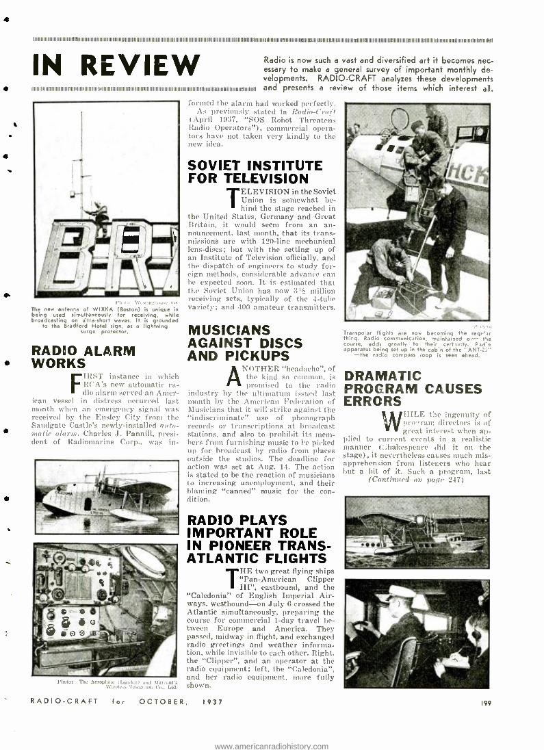
The new antenna of WIXKA (Boston) is unique in being used simultaneously for receiving, while broadcasting on ultra -short waves. It is grounded
to the Bradford Hotel sign, as a lightning surge protector.
RADIO ALARM WORKS
FIRST instance in which RCA's new automatic ra- dio alarm served an Amer-
ican vessel in distress occurred last month when an emergency signal was received by the Ensley City from the Sandgate Castle's newly -installed auto- matie alarm. Charles J. Pannill, presi- dent of Radiomarine Corp., was in-
l 'Imtoe -'1'ho .erold:wu (London) and 51a,,nrs N'irele:s 'Fele :rel,h Co., Ltd.
RADIO -CRAFT
Radio is now such a vast and diversified art it becomes nec- essary to make a general survey of important monthly de- velopments. RADIO -CRAFT analyzes these developments and presents a review of those items which interest all.
farmed the alarm had worked perfectly. As previously stated in Radio -Craft
April 1937, "SOS Robot Threatens Radio Operators "), commercial opera - Ill's have not taken very kindly to the new idea.
SOVIET INSTITUTE FOR TELEVISION
TELEVISION in the Soviet Union is somewhat be- hind the stage reached in
the United States, Germany and Great Britain, it would seem from an an- nouncement, last month, that its trans- missions are with 120 -line mechanical lens- discs; but with the setting up of an Institute of Television officially, and the dispatch of engineers to study for- eign methods, considerable advance can lie expected soon. It is estimated that the Soviet Union has now 3, million receiving sets, typically of the 4 -tube variety; and 400 amateur transmitters.
MUSICIANS AGAINST DISCS AND PICKUPS
( Vl'l I l':It "headache ", of the kind so common, is promised to the radio
industry by the ultimatum issued last month by the American Federation of Musicians that it will strike against the "indiscriminate" use of phonograph records or transcriptions at broadcast stations, and also to prohibit its mem- bers from furnishing music to he picked up for broadcast by radio from places outside the studios. The deadline for action was set at Aug. 14. The action is stated to be the reaction of musicians to increasing unemployment, and their blaming "canned" music for the con- dition.
RADIO PLAYS IMPORTANT ROLE IN PIONEER TRANS- ATLANTIC FLIGHTS
THE two great flying ships "Pan-American Clipper III ", eastbound, and the
"Caledonia" of English Imperial Air- ways, westbound -on July 6 crossed the Atlantic simultaneously, preparing the course for commercial 1 -day travel be- tween Europe and America. They passed, midway in flight, and exchanged radio greetings and weather informa- tion, while invisible to each other. Right. the "Clipper ", and an operator at the radio equipment; left, the "Caledonia ", and her radio equipment, more fully shown.
for OCTOBER, 1937
Transpolar flights are now becoming the , r
thing. Radio communication, maintained ov e t course, adds greatly to their certimty. Part apparatus being set up in the cab n of the ANT
-the radio compass loop is seen ahead.
DRAMATIC PROGRAM CAUSES ERRORS 1 HILE the ingenuity of
pro' ram directors is of great interest when ap-
plied to current events in a realistic manner (:;hakespeare did it on the stage), it nevertheless causes much mis- apprehension from listeners who hear but a bit of it. Such a program, last
(Continued on page 247)
199
www.americanradiohistory.com
440.00 trTES 91113 CYCLES) D
(466.16 CYCLES 329.63 CYCLES E
( 493.86 CYCLES 349.23 CYCLES, F
(261.63 CYCLES 369.99 CYCLES Fe
(2rr.le CYCLES 39200 CYCLES, G
(293.66 CYCLES 415.30 CY,E5) Ge
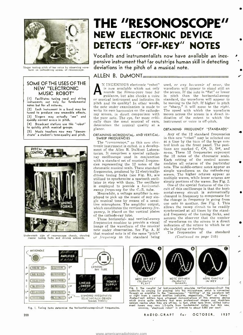
Singer testing pitch of her voice by observing wave- form on cathode -ray screen of resonoscope.
SOME OF THE USES OF THE NEW "ELECTRONIC
MUSIC ROBOT" (I) Facilitates tuning reed and string instruments not only for fundamental notes but for all octaves. (2) Each instrument in a band may be tuned to produce new ensemble effects. (3) Singers may actually "see" and quickly correct errors in pitch. (4) Broadcast stations use this "robot" to quickly pitch musical groups. (5) Music teachers now may "demon- strate" a student's tone -quality and pitch.
Underneath side of resonoscope chassi , showing master tuning forks and driving solenoids.
THE "RESONOSCOPE" NEW ELECTRONIC DEVICE DETECTS "OFF -KEY" NOTES Vocalists and instrumentalists now have available an inex- pensive instrument that far outstrips human skill in detecting deviations in the pitch of a musical note.
ALLEN B. DuMONT01011110101111llli llllllllllllllllllllllllllllllll0011llllll101111110lllllllllllllllllllllllllllllllllllllllllllllllllll
N INGENIOUS electronic "robot" is now available which not only sounds the Simon -pure tone for guidance, but also checks a voice
or musical instrument and indicates its pitch and its quality! In other words, the note under examination is made to write its own harmonics on the cathode - ray screen, in direct comparison with the pure note. The eye, far more criti- cally than the most musical of ears, determines the musical quality at a glance.
OBTAINING HORIZONTAL- AND VERTICAL - SWEEP FREQUENCIES The "resonoscope," as this new elec-
tronic instrument is called, is a develop- ment of the Allen B. DuMont Labora- tories. It comprises a special cathode - ray oscilloscope used in conjunction with a standard set of musical frequen- cies representing the 12 notes of the chromatic musical scale. These standard frequencies, produced by 12 electrically - driven tuning forks (see Fig. B), are utilized to synchronize a sawtooth oscil- lator in step with them. The oscillator is employed to provide a horizontal- ,weep frequency for the C.-R. tube.
Meanwhile, a voltage amplifier is em- ployed to pick up the music of any sin- gle musical tone by means of a sensi- tive microphone. The amplifier output, which constitutes the vertical -sweep fre- quency, is placed on the vertical plates of the cathode -ray tube.
These horizontal- and vertical -sweep frequencies combine to provide a visual image of the waveform of the musical note under observation. See Fig. A. If that musical note is of the same "pitch" or fregffeney as the standard being
A
A'
B
C
Ce
D
MICROPHONE
o AMPLIFIER
LINEAR /SWEEP
POWER SUPPLY
STANDARD FREQUENCIES (ELECTRICALLY- DRIVEN
TUNING FORKS)
Fig. I. Tuning forks determine the horizontal -sweep- circuit frequencies.
200
used, or any harmonic of same, the waveform will appear to stand still on the screen. If the note is "flat" or lower in pitch than the horizontal -sweep standard, the waveform will appear to be moving to the left. if higher in pitch or "sharp," it will move to the right. The speed with which the waveform moves across the screen is a direct in- dication of the extent to which the instrument or voice is off -pitch.
OBTAINING FREQUENCY "STANDARDS"
Any of the 12 standard frequencies in this new "robot" may be selected one at a time by the turn of the large con- trol knob on the front panel. The posi- tions are marked C, C *, D, D#, and so -on. These 12 frequencies represent the 12 notes of the chromatic scale. Each setting of the control accom- modates all octaves of the particular note. The middle- octave notes appear as simple waveforms on the cathode -ray screen. The higher octaves appear as multiple waves, while lower octaves are simply portions of the waves. See Fig. 2.
One of the special features of the cir- cuit of this oscilloscope is that the hori- zontal -sweep circuit is automatically changed in frequency to compensate for the change in frequency in going from one note to another. See Fig. 1. This allows the sweep circuit to be readily synchronized at all times by the stand- ard frequency of the tuning forks, and assures the observer that the number of waveforms on the screen is a direct indication of the octave to which he or she is playing or tuning.
The frequencies of the standard (Continued on page 245)
y s t ; f t t
s ¡ s
NOTE OFF -KEY (SLFLAT)v
0 s
t t L s r
NOTE OFF -KEY (SLI
SHARP)
0 0 NOTE EXACTLY
IN -KEY
Fig. 2. The vocalist (or instrumentalist) provides vertical -sweep-circuit fre- quencies by singing (or playing) into the microphone; which is connected through an amplifier to the " resonoscope." "Drifting" of the waveform left or right from a central position indicates. respectively. "flat" or "sharp." Radio-Craft editors have witnessed demonstrations of this amazing device which prove quite definitely that even professional singers and musicians seldom realize when they are off -key. In fact. other tests show. skilled instru- ment tuners may vary I/3 -cycle from fundamental notes; but this new.
uncanny. "electronic robot" is precise to about 0.002 per cent!
RADIO -CRAFT for OCTOBER, 1937
www.americanradiohistory.com
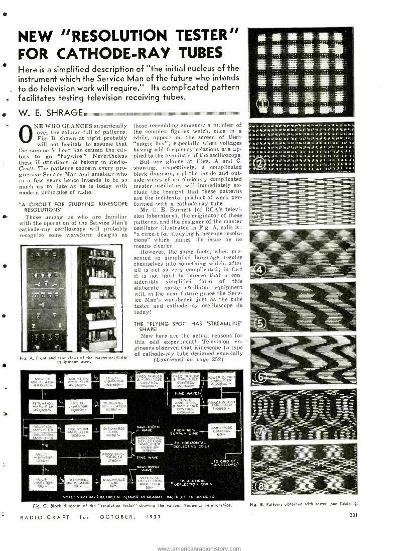
NEW "RESOLUTION TESTER" FOR CATHODE -RAY TUBES Here is a simplified description of "the initial nucleus of the instrument which the Service Man of the future who intends
, to do television work will require." Its complicated pattern , facilitates testing television receiving tubes.
W. E. SH RAGE IIIIIIIIIIIIIIIIIIIIIB 111111111111111111111111111111111111111111111111111111111111111111111111111111111111111111111111111111111111111111
ONE WHO GLANCES superficially over the column -full of patterns, Fig. B, shown at right probably will not hesitate to assume that
the summer's heat has caused the edi- tors to go "haywire." Nevertheless these illustrations do belong in Radio - Craft. The patterns concern every pro- gressive Service Man and amateur who in a few years hence intends to be as much up to date as he is today with modern principles of radio.
"A CIRCUIT FOR STUDYING KINESCOPE RESOLUTIONS"
Those among us who are familiar with the operation of the Service Man's cathode -ray oscilloscope will probably recognize some waveform designs as
Fig. A. Front and rear ews of the master- oscillator equipment used.
those resembling somehow a number of the complex figures which, once in a while, appear on the screen of their "magic box "; especially when voltages having odd frequency relations are ap- plied to the terminals of the oscilloscope.
But one glance at Figs. A and C, showing, respectively, a complicated block diagram, and the inside and out- side views of an obviously complicated master oscillator, will immediately ex- clude the thought that these patterns are the incidental product of work per- formed with a cathode -ray tube.
Mr. C. E. Burnett (of RCA's televi- sion laboratory), the originator of these patterns, and the designer of the master oscillator illustrated in Fig. A, calls it: "a circuit for studying Kinescope resolu- tions" which makes the issue by no means clearer.
However, the same facts, when pre- sented in simplified language resolve themselves into something which, after all is not so very complicated; in fact it is not hard to foresee that a con- siderably simplified form of this elaborate master- oscillator equipment will, in the near future grace the Serv- ice Man's workbench just as the tube tester and cathode -ray oscilloscope do today!
THE "FLYING SPOT' HAS "STREAMLINE" SHAPE! Now here are the actual reasons for
this odd experiment! Television en- gineers observed that Kinescope (a type of cathode -ray tube designed especially
(Continued on page 252)
MASTER OSCILLATOR 493920 --
ISOLATION A PLIFIER 493920 .
ISOLATION AMPLIFIER ISOLATION AMPLIFIER
ISOLATION AMPLIFIER 493920-
MULTI- VIBRATOR 70,560-Y
ISOLATION AMPLIFIER
IQO8O'..
MULTI - VIBRATOR 246.960-.
BLOCKING OSCILLATOR
IQOBO.
DISCHARGE TUBE 0OBO-..
r REO. TRIPLER Q AMPLITUDE
CONTROL 74O,BBO-'.
MULTI - VIBRATOR
FREQUENCY TRIPLER
SAW -TOOTH WAVE
I. OH I ICON TAL DEFLECTION AMPLI FIER
IoCBO OR
'SINE WAVE
SAW-TOOTH 7- WAVE
F REQ. T RIPLER Q AMPLITUDE
CONTROL 2222640'-
1 S NE NAVES
TUNEO AMPLIE IE R
Q AMPLITUDE CONTROL 740860--
FROM 60,. SUPPLY LINE
MULTI- VIBRATOR
IBO. I BLOCKING
OSCILLATOR 30'x.
POWER OUTPUT AMPLIFIER 2222640-
POWER OUTPI;' AMPLIFIER 740,660--
TO HORIZONTAL DEFLECTING COILS
AMPLITUDE CONTROL
TO GAIO OF. ' KINE SCOPE
TO VERTICAL DEFLECTION COILS
NOTE NUMERALS BETWEEN BLOCKS DESIGNATE RATIO OF FREQUENCIES
Fig. C. Block diagram of the "resolution tester" showing the various frequency relationships.
RADIO -CRAFT for OCTOBER, 1937
sxsasar:ssmsara. z - asT :ao. kak 4 4 k: -
sk a - 4 -
<'ï<}C.:M1::<:sT< :SSs-:::::'r:: :
'krks:ks:kssk52' k6k::ka:ki:ka::_::::. s-' .
ísks:aAk::kaai:::::: _::>::::::::::="::
Fig. B. Patterns obtained with tester (see Table I).
201
www.americanradiohistory.com
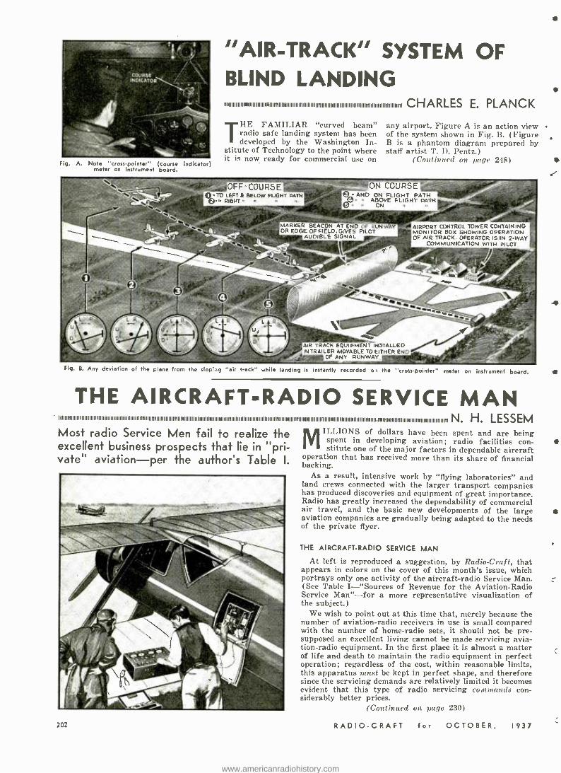
Fig. A. Note "cross- pointer" (course indicator) meter on instrument board.
"AIR- TRACK" SYSTEM OF BLIND LANDING IIIIIIIIIIIIIIIIIIIIIIIIIIIIIIIIIIIIIIIIIIIIIIIIIIIIIIIIIIIIIIIIIIIIIIIIIIIIIIIIIIIIIIIIIIIIIIIIIIIIIIIIIIIIIIIIIIIII CHARLES E. PLANCK
THE FAMILIAR "curved beam" radio safe landing system has been developed by the Washington In-
stitute of Technology to the point where it is now ready for commercial use on
OFF COURSE 0. TO LEFT A BELOW FLOHT PATH ©. RIGW - -
any airport. Figure A is an action view of the system shown in Fig. B. (Figure B is a phantom diagram prepared by staff artist T. D. Pentz.)
(Cantfinued on page 248)
ON COURSE'' ©- ANO ON FLIGHT PATH
Ø. ABOVE FLIGHT PATH © ON
M 'K UN OR EDGE OF FIELD. GIVES PILOT
AUDIBLE SIGNAL
AIRPORT CONTROL TOWER CONTAINING MONITOR BOX SHOWING OPERATION OF AIR TRACK. OPERATOR IS IN 2 -WAY
COMMUNICATION WITH PILOT.
AIR TRACK EQUIPMENT INSTALLED IN TRAILER MOVABLE TO EITHER END
OF ANY RUNWAY.
Fig. B. Any deviation of the pane from the slopi.ig "air track" while landing is instantly recorded of the "cross- pointer" meter on instrument board.
THE AIRCRAFT -RADIO SERVICE MAN N. H. LESSEM
Most radio Service Men fail to realize the excellent business prospects that lie in "pr - vate" aviation -per the author's Table I.
MILLIONS of dollars have been spent and are being spent in developing aviation; radio facilities con- stitute one of the major factors in dependable aircraft
operation that has received more than its share of financial backing.
As a result, intensive work by "flying laboratories" and land crews connected with the larger transport companies has produced discoveries and equipment of great importance. Radio has greatly increased the dependability of commercial air travel, and the basic new developments of the large aviation companies are gradually being adapted to the needs of the private flyer.
THE AIRCRAFT -RADIO SERVICE MAN
At left is reproduced a suggestion, by Radio -Craft, that appears in colors on the cover of this month's issue, which portrays only one activity of the aircraft -radio Service Man. (See Table I- "Sources of Revenue for the Aviation -Radio Service Man" -for a more representative visualization of the subject.)
We wish to point out at this time that, merely because the number of aviation -radio receivers in use is small compared with the number of home -radio sets, it should not be pre- supposed an excellent living cannot be made servicing avia- tion -radio equipment. In the first place it is almost a matter of life and death to maintain the radio equipment in perfect operation; regardless of the cost, within reasonable limits, this apparatus must be kept in perfect shape, and therefore since the servicing demands are relatively limited it becomes evident that this type of radio servicing commands con- siderably better prices.
(Continued on page 230)
RADIO -CRAFT for OCTOBER, 1937
{
www.americanradiohistory.com
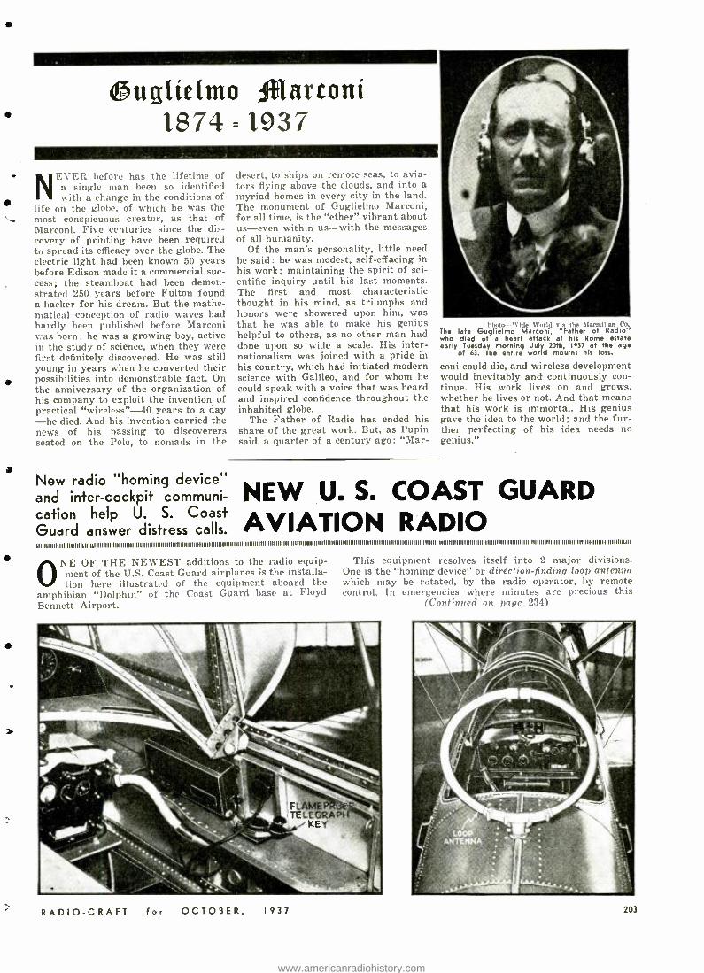
1J$ ugiíeYuYo fbiarconí 1874=1937
NEVER before has the lifetime of a single man been so identified with a change in the conditions of
life on the globe, of which he was the most conspicuous creator, as that of Marconi. Five centuries since the dis- covery of printing have been required to spread its efficacy over the globe. The electric light had been known 50 years before Edison made it a commercial suc- cess; the steamboat had been demon- strated 250 years before Fulton found a backer for his dream. But the mathe- matical conception of radio waves had hardly been published before Marconi was born; he was a growing boy, active in the study of science, when they were first definitely discovered. He was still young in years when he converted their possibilities into demonstrable fact. On the anniversary of the organization of his company to exploit the invention of practical "wireless " -40 years to a day -he died. And his invention carried the news of his passing to discoverers seated on the Pole, to nomads in the
New radio "homing device" and inter -cockpit communi- cation help U. S. Coast Guard answer distress calls.
desert, to ships on remote seas, to avia- tors flying above the clouds, and into a myriad homes in every city in the land. The monument of Guglielmo Marconi, for all time, is the "ether" vibrant about us -even within us -with the messages of all humanity.
Of the man's personality, little need be said: he was modest, self- effacing in his work; maintaining the spirit of sci- entific inquiry until his last moments. The first and most characteristic thought in his mind, as triumphs and honors were showered upon him, was that he was able to make his genius helpful to others, as no other man had done upon so wide a scale. His inter- nationalism was joined with a pride in his country, which had initiated modern science with Galileo, and for whom he could speak with a voice that was heard and inspired confidence throughout the inhabited globe.
The Father of Radio has ended his share of the great work. But, as Pupin said, a quarter of a century ago: "Mar-
1 'hotn- -Wide World via the Marmillen Co The late Guglielmo Marconi, "Father of Radio" who died of a heart attack at his Rome estate early Tuesday morning July 20th, 1937 at the age
of 63. The entire world mourns his loss.
coni could die, and wireless development would inevitably and continuously con- tinue. His work lives on and grows, whether he lives or not. And that means that his work is immortal. His genius gave the idea to the world; and the fur- ther perfecting of his idea needs no genius."
NEW U. S. COAST GUARD AVIATION RADIO
I I I I I I I I I I I I I I I I I I I I I I I I I I I I I I I I I I I I I I I I I I I I I I I I I I I I I I I I I I I I I I I I I I I I I I I I I i l l l l l l l l l l l l l l l l l l l l l l l l l l
ONE OF THE NEWEST additions to the radio equip- ment of the U.S. Coast Guard airplanes is the installa- tion here illustrated of the equipment aboard the
amphibian "Dolphin" of the Coast Guard base at Floyd Bennet Airport.
This equipment resolves itself into 2 major divisions. One is the "homing device" or direction -finding loop antenna which may be rotated, by the radio operator, by remote control. In emergencies where minutes are precious this
(Continued on page 234)
RADIO -CRAFT for OCTOBER, 1937 203
www.americanradiohistory.com
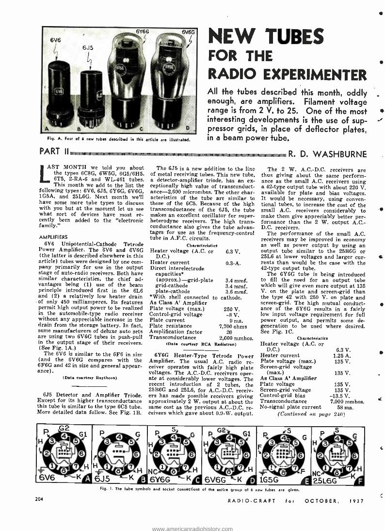
Fig. A. Four of 6 new tubes described in this article are illustrated.
NEW TUBES FOR THE RADIO EXPERIMENTER All the tubes described this month, oddly enough, are amplifiers. Filament voltage range is from 2 V. to 25. One of the most interesting developments is the use of sup- pressor grids, in place of deflector plates, in a beam power tube.
PART R. D. WASHBURNE LAST MONTH we told you about
the types 6C8G, 6W5G, 6G5/6H5, 6T5, 2 -RA -6 and WL-461 tubes. This month we add to the list the
following types: 6V6, 6J5, 6Y6G, 6V6G, 1G5A, and 25L6G. Next month we'll have some more tube types to discuss with you but at the moment let us see what sort of devices have most re- cently been added to the "electronic family."
AMPLIFIERS
6V6 Unipotential- Cathode Tetrode Power Amplifier. The 6V6 and 6V6G (the latter is described elsewhere in this article) tubes were designed by one com- pany primarily for use in the output stage of auto -radio receivers. Both have similar characteristics, the chief ad- vantages being (1) use of the beam principle introduced first in the 6L6 and (2) a relatively low heater drain of only 450 milliamperes. Its features permit high output power to be realized in the automobile -type radio receiver without any appreciable increase in the drain from the storage battery. In fact, some manufacturers of deluxe auto sets are using two 6V6G tubes in push -pull in the output stage of their receivers. (See Fig. 1A.)
The 6V6 is similar to the 6F6 in size (and the 6V6G compares with the 6F6G and 42 in size and general appear- ance).
(Data courtesy Raytheon)
6J5 Detector and Amplifier Triode. Except for its higher transconductance this tube is similar to the type 6C5 tube. More detailed data follow. See Fig. 1B.
The 6J5 is a new addition to the line of metal receiving tubes. This new tube, a detector -amplifier triode, has an ex- ceptionally high value of transconduct- ance -2,600 micromhos. The other char- acteristics of the tube are similar to those of the 6C5. Because of the high transconductance of the 6J5, the tube makes an excellent oscillator for super- heterodyne receivers. The high trans - conductance also gives the tube advan- tages for use as the frequency -control tube in A.F.C. circuits.
Characteristics Heater voltage (A.C. or 6.3 V.
D.C.) Heater current 0.3 -A. Direct interelectrode
capacities` (approx.) -grid -plate 3.4 mmf. grid- cathode 3.4 mmf. plate- cathode 3.6 mmf.
*With shell connected to cathode. As Class A' Amplifier Plate voltage (max.) 250 V. Control -grid voltage -8 V. Plate current 9 ma. Plate resistance 7,700 ohms Amplification factor 20 Transconductance 2,600 mmhos.
(Data courtesy RCA Radiotron)
6Y6G Heater -Type Tetrode Power Amplifier. The usual A.C. radio re- ceiver operates with fairly high plate voltages. The A.C.-D.C. receivers oper- ate at considerably lower voltages. The recent introduction of 2 tubes, the 25B6G and 25L6, for A.C.-D.C. receiv- ers has made possible receivers giving approximately 2 W. output at about the same cost as the previous A.C. -D.C. re- ceivers which gave about 0.9 -W. output.
The 2 W. A.C. -D.C. receivers are thus giving about the same perform- ance as the small A.C. receivers using a 42 -type output tube with about 220 V. available for plate and bias voltages. It would be necessary, using conven- tional tubes, to increase the cost of the small A.C. receivers considerably to make them give appreciably better per- formance than the 2 W. output A.C: D.C. receivers.
The performance of the small A.C. receivers may be improved in economy as well as power output by using an output tube similar to the 25B6G or 25L6 at lower voltages and larger cur- rents than would be the case with the 42 -type output tube.
The 6Y6G tube is being introduced to fill the need for an output tube which will give even more output at 135 V. on the plate and screen -grid than the type 42 with 250 V. on plate and screen -grid. The high mutual conduct- ance of the 6Y6G results in a fairly low input voltage requirement for full power output, and permits some de- generation to be used where desired. See Fig. 1C.
Characteristics Heater voltage (A.C. or
D.C.) 6.3 V. Heater current 1.25 A. Plate voltage (max.) 135 V. Screen -grid voltage
(max.) 135 V. As Class A' Amplifier Plate voltage 135 V. Screen -grid voltage 135 V. Control -grid bias -13.5 V. Transconductance 7,000 mmhos. No- signal plate current 58 ma.
(Continued on. page 240)
HP3 t 2
© 6V6
4 :::
GI.
0 H
KQ
p3
2
H 0 _ 6J5
0 ...
5 G
p 7
K d
H
p3 4 ::: . ":
6Y6GO
5 G
p 7
H
Kd
3 24
p... G1
0
4s F
` 2'::C
iG5Gß
G
O
©
H© 4 ©G
2 ::: O
O " H
25L6 á 8 .
8 © 6V6G
e H
K d 204
Fig. I. The tube symbols and socket connections of tke entire group of 6 new tubes are given
RADIO -CRAFT for OCTOBER, 1937
www.americanradiohistory.com
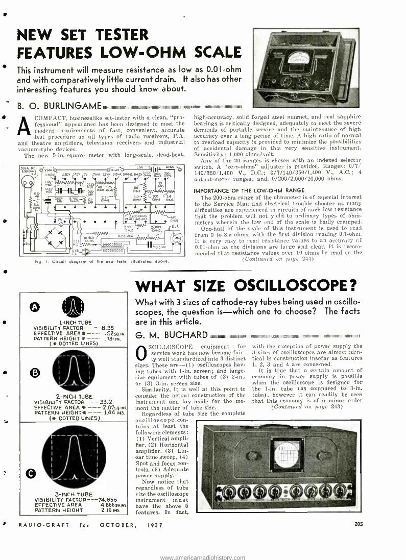
NEW SET TESTER FEATURES LOW -OHM SCALE This instrument will measure resistance as low as 0.0I -ohm and with comparatively little current drain. It also has other interesting features you should know about.
B. O. COMPACT, businesslike set -tester with a clean, "pro- fessional" appearance has been designed to meet the modern requirements of fast, convenient, accurate test procedure on all types of radio receivers, P.A.
and theatre amplifiers, television receivers and industrial vacuum -tube devices.
The new 5- in.- square meter with long- scale, dead -beat,
.001-A..DC 0 VMA T R..) 1.400v
AS,,, EG
MEG¡-11Hk l 'oMOF- ó.m°5-
0 WM50 1.5V. MECS
(350V (1413V L.
7MA 35.E 140%A 231/EG5 =MECS -
0 s- M`
300
01
]` al 4> [ f0,460 0.22
OJJ' OHMS NEG ns~ 1006=öl9
e 1 1
MESG5
MP
r40 CTS OMIS 0116
2.S-.l OHMS ern
110
OMIS
OHMS
1 1
w6
30
C 300 C.34 OHMS OHMS
4 4 4
3.0000HM5 *FROOHMSppf HM
*l.Jt OS 3000-' 2.000 ` OlA
OHMS OHMS
FG
t
ww /", 1`"'J
11771 .
Fig. I. Circuit diagram of the new tester illustrated above.
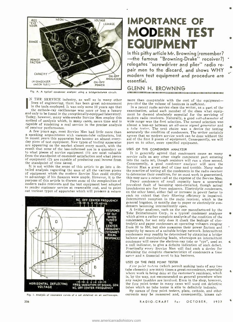
o 1 -INCH TUBE
VISIBILITY FACTOR - - -- 8.35 EFFECTIVE AREA1k - - -- .525g.iw. PATTERN HEIGHT * - - --
( AF DOTTED LINES)
O
2 -INCH TUBE VISIBILITY FACTOR -- -33.2 EFFECTIVE AREA * - -- 2.075o .ias PATTERN HEIGHT-A - -- 1.44 INS.
(ìF DOTTED LINES)
3 -INCH TUBE VISIBILITY FACTOR - -- 74.656 EFFECTIVE AREA 4.666so.INs PATTERN HEIGHT 2.16bä.
high- accuracy, solid forged steel magnet, and real sapphire bearings is critically designed, adequately to meet the severe demands of portable service and the maintenance of high accuracy over a long period of time. A high ratio of normal to overload capacity is provided to minimize the possibilities of accidental damage in this very sensitive instrument. Sensitivity: 1,000 ohms /volt.
Any of the 20 ranges is chosen with an indexed selector switch. A "zero- ohms" adjuster is provided. Ranges: 0/7/ 140/350/1,400 V., D.C.; 0/7/140/350/1,400 V., A.C.; 4 output -meter ranges; and, 0/200/2,000/20,000 ohms.
IMPORTANCE OF THE LOW -OHM RANGE
The 200 -ohm range of the ohmmeter is of especial interest to the Service Man and electrical trouble shooter as many difficulties are experienced in circuits of such low resistance that the problem will not yield to ordinary types of ohm- meters wherein the low end of the scale is badly cramped.
One -half of the scale of this instrument is used to read from 0 to 3.5 ohms, with the first division reading 0.1 -ohm. It is very easy to read resistance values to an accuracy of 0.01 -ohm as the divisions are large and clear. It is recom- mended that resistance values over 10 ohms be read on the
(Continued on page 244)
WHAT SIZE OSCILLOSCOPE? What with 3 sizes of cathode -ray tubes being used in oscillo- scopes, the question is -which one to choose? The facts are in this article.
G. M. BUCI-IARD IIIIIIIIIIIIIIIIIIIIIIIIIIIIIIIIIIIIIIIIIIIIIIIIli: 11111: I: IIIIIIIiiI11111: 111111111111111111111111111111111111111111111111111111111 :1:1
SCILLOSCOPE equipment for service work has now become fair- ly well standardized into 3 distinct
sizes. These are -(1) oscilloscopes hav- ing tubes with 1 -in. screen; and large - size equipment with tubes of (2) 2 -in., or (3) 3 -in. screen size.
Similarity. It is well at this point to consider the actual construction of the instrument and lay aside for the mo- ment the matter of tube size.
Regardless of tube size the complete oscilloscope con- tains at least the following elements: (1) Vertical ampli- fier, (2) Horizontal amplifier, (3) Lin- ear time sweep, (4) Spot and focus con - trols, (5) Adequate power supply.
Now notice that regardless of tube size the oscilloscope instrument must have the above 5 features. In fact,
f RADIO -CRAFT for OCTOBER, 1937
with the exception of power supply the 3 sizes of oscilloscopes are almost iden- tical in construction insofar as features 1, 2, 3 and 4 are concerned.
It is true that a certain amount of economy in power supply is possible when the oscilloscope is designed for the 1 -in. tube (as compared to 3 -in. tube), however it can readily be seen that this economy is of a minor order
(Continued on page 243)
205
www.americanradiohistory.com
,665 EYE'
VISOR
RANGE
NEON - VOLTAGE
LEAKAGE
POWER FACTOR
CAPACITY
(A CONDENSER ON-OFF UNDER TEST - - ; j POWER
ON-OFF ANALYZER
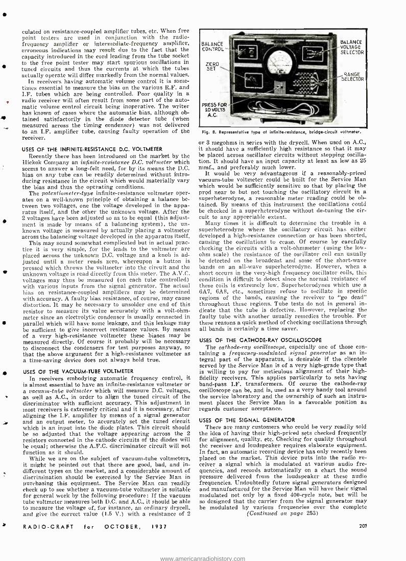
Fig. A. A typical condenser analyzer using a bridge -balance circuit.
IN THE SERVICE industry, as well as in many other lines of engineering, there has been great advancement in the tools employed. It was only some 10 years ago that the cathode -ray oscilloscope was more or less a luxury
and only to be found in the exceptionally- equipped laboratory. Today, however, many wide -awake Service Men employ this method of analysis which, in many cases, saves time and is capable of rendering a real service in the precise analysis of receiver performance.
A few years ago, most Service Men had little more than a speaking acquaintance wiih vacuum -tube voltmeters, but in recent years this apparatus has become an almost every- day piece of test equipment. New types of testing apparatus are appearing on the market almost every month, with the result that some of the less -informed are in a quandary as to what pieces of service equipment (1) are most valuable from the standpoint of customer satisfaction and what pieces of equipment (2) are capable of producing real income from the standpoint of time saved.
It is not within the scope of this article to go into a de- tailed analysis regarding the uses of all the various pieces cf equipment which the modern Service Man could employ to advantage if his finances were ample. However, it is the purpose of this article to discuss some of the complexities of modern radio receivers and the test equipment best adapted to render customer service at reasonable cost, and to point out various types of apparatus which will produce a return
16 0
KC. OFF CENTER FREQUENCY -15 -10 -5 0 +.5.+10+15
14
I?
HORIZONTAL DEFLECTING VOLTAGE
RESPONCE
OF SET WHEN
TUNED TO
CENTER FREOUENCY (SYMMET-
RICAL RESPONCE)
-15-10 -5 0 +5+10+15 FREQ. VARIATION OF SIGNAL GEN. KC. OFF CENTER FREQUENCY
Fig. I. Analysis of resonance curves of a set obtained on an oscilloscope.
206
IMPORTANCE OF MODERN TEST EQUIPMENT In this pithy article Mr. Browning (remember? -the famous "Browning- Drake" receiver ?)
relegates "screwdriver and plier" radio re- pair men to the discard, and shows WHY modern test equipment and procedure are essential.
GLENN H. BROWNING
more than comparable with the cost of the equipment- provided the the volume of business is sufficient.
In a recent radio service class the writer, as a part of the examination, asked each member of the class what equip- ment he deemed absolutely essential for the servicing of modern radio receivers. Naturally, a good volt -ohmmeter of wide range was the first selection. The second selection was almost a toss -up between an all -wave signal generator and a tube tester. The next choice was a device for testing accurately the condition of condensers. The writer certainly agrees that no modern service work can be done without the aid of the first 3 pieces of equipment. Consequently, we will pass on to other, more specified equipment.
USES OF THE CONDENSER ANALYZER It is generally agreed that condensers cause as many
service calls as any other single component part entering into the radio set, though resistors will run a close second. Consequently, a good condenser analyzer will save the Service Man a great deal of time and trouble. Many make the practice of testing all the condensers in the radio receiver to determine their condition, for as most work is guaranteed, this may save a return call at the expense of the Service Man.
Paper condensers of small capacity have a somewhat prevalent fault of becoming open- circuited, though actual breakdowns are far from unknown. Electrolytic condensers, on the other hand, either fail or increase in power factor to such an extent that their filtering efficiency is impaired. Intermittent reception in the radio receiver, which is the general bugaboo, is usually due to paper or electrolytic con- densers becoming intermittently open.
A bridge analyzer, such as the one manufactured by the Tobe Deutschmann Corp., is a typical condenser analyzer which gives a rather complete analysis of the condition of the condensers, for not only does it check the leakage of elec- trolytic and paper condensers at operating voltages ranging from 50 to 550, but also measures their power factors and capacity by means of a suitable bridge network. Intermittent condensers may readily be determined by obtaining a bridge balance and manipulating leads, whereupon an intermittent condenser will cause the electron -ray tube or "eye ", used as a null indicator, to give a definite indication of such defect. Practically every Service Man will find such a device for obtaining the complete characteristics of condensers a time saver and a financial asset to his business.
USES OF THE FREE POINT TESTER
Free point testers (which permit making tests of any two tube elements) are many times a great convenience, especially where work is being done at the customer's residence, which is, by the way, not recommended as general procedure when any major troubles are involved. Even in the shop, however, the free point tester in many cases will weed out defective tubes which no tube tester is able to definitely indicate.
By means of free point testers, plate, cathode, and other currents may be measured and, consequently, biases cal-
RADIO-C RAFT for OCTOBER, 1937
t
t
www.americanradiohistory.com
culated on resistance- coupled amplifier tubes, etc. When free point testers are used in conjunction with the radio - frequency amplifier or intermediate- frequency amplifier, erroneous indications may result due to the fact that the capacity introduced in the cord leading from the tube socket to the free point tester may start spurious oscillations in tuned circuits and thus the currents at which the tubes actually operate will differ markedly from the normal values.
In receivers having automatic volume control it is some- times essential to measure the bias on the various R.F. and I.F. tubes which are being controlled. Poor quality in a radio receiver will often result from some part of the auto- matic volume control circuit being inoperative. The writer has known of cases where the automatic bias, although ob- tained satisfactorily in the diode detector tube (when measured across the timing condenser) was not delivered to an I.F. amplifier tube, causing faulty operation of the receiver.
USES OF THE INFINITE -RESISTANCE D.C. VOLTMETER Recently there has been introduced on the market by the
Hickok Company an infinite resistance D.C. voltmeter which seems to answer a long -felt need, for by its means the D.C. bias on any tube can be readily determined without intro- ducing resistance in the circuit which would materially vary the bias and thus the operating conditions.
The potentiometer -type infinite -resistance voltmeter oper- ates on a well -known principle of obtaining a balance be- tween two voltages, one the voltage developed in the appa- ratus itself, and the other the unknown voltage. After the 2 voltages have been adjusted so as to be equal (this adjust- ment is made by means of a balancing system), the un- known voltage is measured by actually placing a voltmeter across the balancing voltage developed in the apparatus itself.
This may sound somewhat complicated but in actual prac- tice it is very simple, for the leads to the voltmeter are placed across the unknown D.C. voltage and a knob is ad- justed until a meter reads zero, whereupon a button is pressed which throws the voltmeter into the circuit and the unknown voltage is read directly from this meter. The A.V.C. voltages may thus be measured (on each tube controlled) with various inputs from the signal generator. The actual bias on resistance- coupled amplifiers may be determined with accuracy. A faulty bias resistance, of course, may cause distortion. It may be necessary to unsolder one end of this resistor to measure its value accurately with a volt -ohm- meter since an electrolytic condenser is usually connected in parallel which will have some leakage, and this leakage may be sufficient to give incorrect resistance values. By means of a very high -resistance voltmeter these biases may be measured directly. Of course it probably will be necessary to disconnect the condensers for test purposes anyway, so that the above argument for a high- resistance voltmeter as a time -saving device does not always hold true.
USES OF THE VACUUM -TUBE VOLTMETER
In receivers embodying automatic frequency control, it is almost essential to have an infinite -resistance voltmeter or a vacuum -tube voltmeter which will measure D.C. voltages, as well as A.C., in order to align the tuned circuit of the discriminator with sufficient accuracy. This adjustment in most receivers is extremely critical and it is necessary, after aligning the I.F. amplifier by means of a signal generator
y and an output meter, to accurately set the tuned circuit which is an input into the diode plates. This circuit should be so adjusted that the voltage appearing across the 2 resistors connected in the cathode circuits of the diodes will be equal; otherwise the A.F.C. discriminator circuit will not function as it should.
While we are on the subject of vacuum -tube voltmeters, it might be pointed out that there are good, bad, and in- different types on the market, and a considerable amount of discrimination should be exercised by the Service Man in purchasing this equipment. The Service Man can readily check up to see whether a vacuum -tube voltmeter is suitable for general work by the following procedure: If the vacuum tube voltmeter measures both D.C. and A.C., it should be able to measure the voltage of, for instance, an ordinary drycell, and give the correct value (1.5 V.) with a resistance of 2
RADIO -CRAFT for OCTOBER, 1937
BALANCE CONTROL
ZERO SET
PRESS FOR 10 VOLTS A.C.
In Ils.
BALANCE VOLTAGE SELECTOR
RANGE SELECTOR
Fig. B. Representative type of infinite- resistance, bridge- circuit voltmeter.
or 3 megohms in series with the drycell. When used on A.C., it should have a sufficiently high resistance so that it may be placed across oscillator circuits without stopping oscilla- tion. It should have an input capacity at least as low as 25 mmf., and preferably much lower.
It would be very advantageous if a reasonably -priced vacuum -tube voltmeter could be built for the Service Man which would be sufficiently sensitive so that by placing the prod near to but not touching the oscillatory circuit in a superheterodyne, a reasonable meter reading could be ob- tained. By means of this instrument the oscillations could be checked in a superheterodyne without de- tuning the cir- cuit to any appreciable extent.
Many times it is difficult to determine the trouble in a superheterodyne where the oscillatory circuit has either developed a high- resistance connection or has been shorted, causing the oscillations to cease. Of course by carefully checking the circuits with a volt -ohmmeter (using the low - ohm scale) the resistance of the oscillator coil can usually be detected on the broadcast and some of the short -wave bands on an all -wave superheterodyne. However, when a short occurs in the very -high frequency oscillator coils, this condition is difficult to detect since the normal resistance of these coils is extremely low. Superheterodynes which use a 6A7, 6A8, etc., sometimes refuse to oscillate in specific regions of the bands, causing the receiver to "go dead" throughout these regions. Tube tests do not in general in- dicate that the tube is defective. However, replacing the faulty tube with another usually remedies the trouble. For these reasons a quick method of checking oscillations through all bands is certainly a time saver.
USES OF THE CATHODE -RAY OSCILLOSCOPE The cathode -ray oscilloscope, especially one of those con-
taining a frequency -modulated signal generator as an in- tegral part of the apparatus, is desirable if the clientele served by the Service Man is of a very high -grade type that is willing to pay for meticulous alignment of their high - fidelity receivers. This applies particularly to sets having band -pass I.F. transformers. Of course the cathode -ray oscilloscope can be, and is, used as a very handy tool around the service laboratory and the ownership of such an instru- ment places the Service Man in a favorable position as regards customer acceptance.
USES OF THE SIGNAL GENERATOR There are many customers who could be very readily sold
the idea of having their high -priced sets checked frequently for alignment, quality, etc. Checking for quality throughout the receiver and loudspeaker requires elaborate equipment. In fact, an automatic recording device has only recently been placed on the market. This device puts into the radio re- ceiver a signal which is modulated at various audio fre- quencies, and records automatically on a chart the sound pressure delivered from the loudspeaker at these audio frequencies. Undoubtedly future signal generators designed and manufactured for the Service Man will have their signal modulated not only by a fixed 400 -cycle note, but will be so designed that the carrier from the signal generator may be modulated by various frequencies over the complete
(Continued on page 253)
207
www.americanradiohistory.com
SHIPS COMPASS
SIGNAL
SHIPS 180°
COURSE
SHIP'S COURSE - "EXACTLY NORTH;
POINT OF MIN. SIG . - 10 °EAST OF NORTH.
THIS GIVES STATION BEARING WHEN MAGNET
IC-VARIATION CORRECTIONS ARE MADE.
ON CHART AS USED BY INDIVIDUAL MARINER. DRAW LINE THROUGH STATION AT 10° (VARIATION COR- RECTION) FROM
TRUE NORTH, PROJECT SAME SEAWARD AND GET LINE OF POS- ITION. TWO TRUE
STATION BEARINGS WILL GIVE A-FIX' WHERE THE LINES
POINTER CROSS.
ON RECEIVER CABINET SHIPS
COURSE
II.,.,
PERMANENT- MAGNET DYNAMIC
REPRODUCER
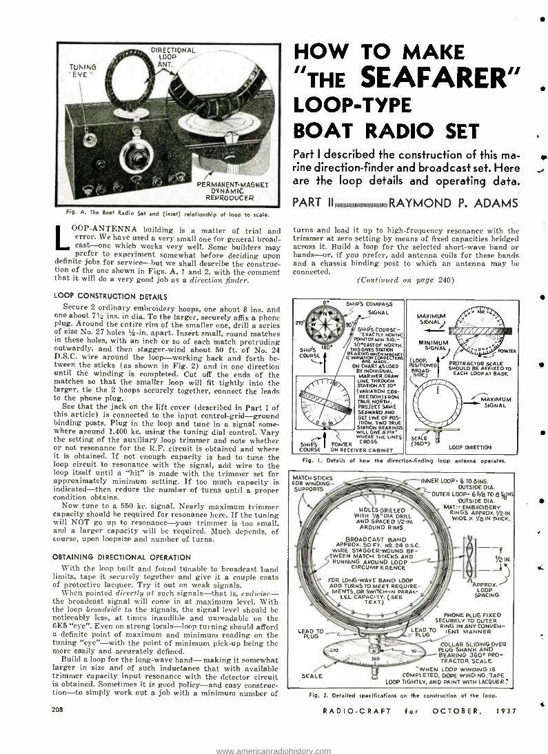
Fig. A. The Boat Radio Set and (inset) relationship of loop to scale.
LOOP-ANTENNA building is a matter of trial and error. We have used a very small one for general broad- cast-one which works very well. Some builders may prefer to experiment somewhat before deciding upon
definite jobs for service -but we shall describe the construc- tion of the one shown in Figs. A, 1 and 2, with the comment that it will do a very good job as a direction finder.
LOOP CONSTRUCTION DETAILS
Secure 2 ordinary embroidery hoops, one about 8 ins. and one about 7% ins. in dia. To the larger, securely affix a phone plug. Around the entire rim of the smaller one, drill a series of size No. 27 holes s -in. apart. Insert small, round matches in these holes, with an inch or so of each match protruding outwardly, and then stagger -wind about 50 ft. of No. 24 D.S.C. wire around the loop- working back and forth be- tween the sticks (as shown in Fig. 2) and in one direction until the winding is completed. Cut off the ends of the matches so that the smaller loop will fit tightly into the larger, tie the 2 hoops securely together, connect the leads to the phone plug.
See that the jack on the lift cover (described in Part I of this article) is connected to the input control -grid - ground binding posts. Plug in the loop and tune in a signal some- where around 1,400 kc. using the tuning dial control. Vary the setting of the auxiliary loop trimmer and note whether or not resonance for the R.F. circuit is obtained and where it is obtained. If not enough capacity is had to tune the loop circuit to resonance with the signal, add wire to the loop itself until a "hit" is made with the trimmer set for approximately minimum setting. If too much capacity is indicated -then reduce the number of turns until a proper condition obtains.
Now tune to a 550 kc. signal. Nearly maximum trimmer capacity should be required for resonance here. If the tuning will NOT go up to resonance -your trimmer is too small, and a larger capacity will be required. Much depends, of course, upon loopsize and number of turns.
OBTAINING DIRECTIONAL OPERATION
With the loop built and found tunable to broadcast band limits, tape it securely together and give it a couple coats of protective lacquer. Try it out on weak signals.
When pointed directly at such signals -that is, endwise- the broadcast signal will come in at maximum level. With the loop broadside to the signals, the signal level should be noticeably less, at times inaudible and unreadable on the 6E5 "eye ". Even on strong locals -loop turning should afford a definite point of maximum and minimum reading on the tuning "eye" -with the point of minimum pick -up being the more easily and accurately defined.
Build a loop for the long -wave band- making it somewhat larger in size and of such inductance that with available trimmer capacity input resonance with the detector circuit is obtained. Sometimes it is good policy -and easy construc- tion-to simply work out a job with a minimum number of
208
HOW TO MAKE "THE SEAFARER" LOOP -TYPE BOAT RADIO SET Part I described the construction of this ma- rine direction- finder and broadcast set. Here are the loop details and operating data.
PART II RAYMOND P. ADAMS
turns and load it up to high- frequency resonance with the trimmer at zero setting by means of fixed capacities bridged across it. Build a loop for the selected short -wave band or bands -or, if you prefer, add antenna coils for these bands and a chassis binding post to which an antenna may be connected.
(Continued on page 240)
MAXIMUM SIGNAL)
MINIMUM SIGNAL
PONTER
(EDDY, POSITIONED
S PROTRACTOR SCALE
BRDAD EACH LOOP AT BASE BE AFFIXED TO
sloE)
1
".---,4A1(IM UM .-" SIGNAL
Fig. I. Details of how the direction -finding loop antenna operates.
MATCH STICKS FOR WINDING - SUPPORTS
INNER LOOP. 6 TD8INS. OUTSIDE DIA.
OUTER LOOP= 65/8 TO 8 VnIS OUTSIDE DIA.
MAT:- EMBROIDERY RINGS APPROX. -IN. WIDE Y8-IN. THICK.
HOLES DRILLED WITH 78" 01A DRILL AND SPACED I /2-IN. AROUND RIMS.
BROADCAST BAND APPROX. 50 FT. N2.24 D.S.C.
WIRE STAGGER-WOUND BE-
5 TWEEN MATCH STICKS AND
RUNNING AROUND LOOP CIRCUMFERENCE
FOR LONG-WAVE BAND LOOP ADD TURNS TO MEET REQUIRE - MENTS,ORSWITCH-IN PARAL-
LEL CAPACITY. (SEE TEXT.)
LEAD TO Z_ PLUG
Y2-IN.
APPROX. APPROX LOOP
SPACING
PHONE PLUG FIXED SECURELY TO OUTER
IN ANY LEAD TO
RING IENT MANNER
NVEN- PLUG
SCALE I
COLLAR SLIDING OVER PLUG SHANK AND BEARING 360° PRO- TRACTOR SCALE
WHEN LOOP WINDING IS COMPLETED. DOPE WINDING, TAPE
LOOP TIGHTLY, AND PAINT WITH LACQUER.`
Fig. 2. Detailed specifications on the construction of the loop.
RADIO -CRAFT for OCTOBER, 1937
*C.
www.americanradiohistory.com
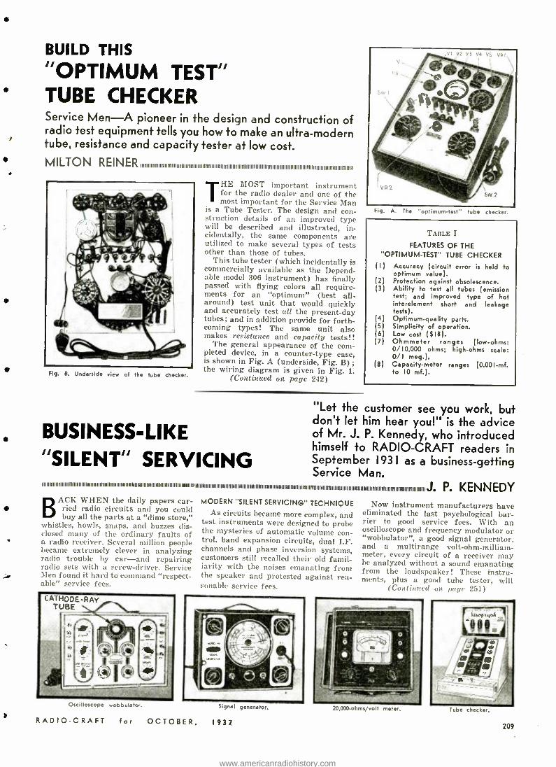
BUILD THIS
"OPTIMUM TEST" TUBE CHECKER Service Men -A pioneer in the design and construction of radio test equipment tells you how to make an ultra- modern tube, resistance and capacity tester at low cost.
MILTON ;11111
Fig. B. Underside view of the tube checker.
THE MOST important instrument for the radio dealer and one of the most important for the Service Man
is a Tube Tester. The design and con- struction details of an improved type will be described and illustrated, in- cidentally, the same components are utilized to make several types of tests other than those of tubes.
This tube tester (which incidentally is commercially available as the Depend- able model 306 instrument) has finally passed with flying colors all require- ments for an "optimum" (best all - around) test unit that would quickly and accurately test all the present -day tubes; and in addition provide for forth- coming types! The same unit also makes resistance and capacity tests!!
The general appearance of the com- pleted device, in a counter -type case, is shown in Fig. A (underside, Fig. B) ; the wiring diagram is given in Fig. 1.
(Continued on page 242)
BUSINESS -LIKE "SILENT" SERVICING
Fig. A. The 'optimum -test' tube checker.
TABLE I
FEATURES OF THE "OPTIMUM-TEST" TUBE CHECKER
(I)
(2) (3)
(4) (5) (6) (7)
Accuracy (circuit error is held to optimum value). Protection against obsolescence. Ability to test all tubes (emission test; and improved type of hot interelement short and leakage tests). Optimum- qualify parts. Simplicity of operation. Low cost ($18). Ohmmeter ranges (low -ohms: 0 /10,000 ohms; high -ohms scale: 0/I meg.).
(8) Capacity -meter ranges (0.001 -mf. to 10 mf.).
"Let the customer see you work, but don't let him hear you!" is the advice of Mr. J. P. Kennedy, who introduced himself to RADIO -CRAFT readers in September 1931 as a business -getting Service Man.
mBIBIInNBInWnIBnnBnmuuBBBnIIIBmnuununllllnlmonifiIIBIBBWimilmommili BIBIBNIImmmmmfNWUnnuumnmmmnumnuuumurinumlunnnu unminnmmminmBJ. P. KENNEDY
BACK WHEN the daily papers car- lied radio circuits and you could buy all the parts at a "dime store,"
whistles, howls, snaps, and buzzes dis- closed many of the ordinary faults of a radio receiver. Several million people became extremely clever in analyzing radio trouble by ear -and repairing radio sets with a screw- driver. Service Men found it hard to command "respect - :ILIt" service fees.
MODERN "SILENT SERVICING" TECHNIQUE As circuits became more complex, and
test instruments were designed to probe the mysteries of automatic volume con- trol, band expansion circuits, dual I.F. channels and phase inversion systems, customers still recalled their old famil- iarity with the noises emanating from the speaker and protested against rea- sonable service fees.
Now instrument manufacturers have eliminated the last psychological bar- rier to good service fees. With an oscilloscope and frequency modulator or "wobbulator ", a good signal generator, and a multirange volt- ohm- milliam- meter, every circuit of a receiver may be analyzed without a sound emanating from the loudspeaker! These instru- ments, plus a good tube tester, will
(Cost inned on pale 251)
Oscilloscope wobbulator.
RADIO -CRAFT for OCTOBER,
Sgn.,l generator.
1937
20,000-oh m s olt meter. Ti_be checker.
209
www.americanradiohistory.com
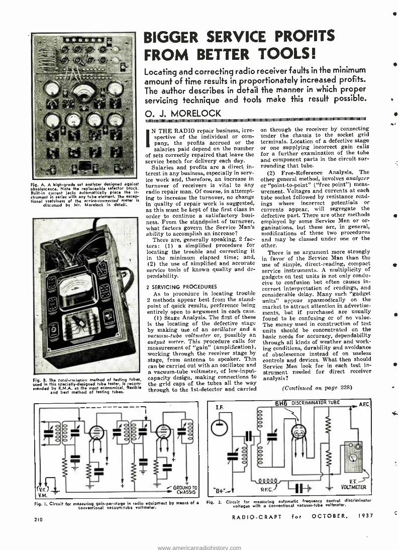
.... .......
Fig. A. A high -grade set analyzer designed against obsolescence. Note the replaceable selector block. Beilt -in current jacks automatically place the in- strument in series with any tube element. The excep- tional usefulness of the arriee- connected meter is
discussed by Mr. Morelock in detail.
Fig. B. The two/. rn iavion method of testing tube ,
used in this specially- designed tube tester, is recom- mended by R.M.A. as the most economical, flexible
and but method of testing tubes.
BIGGER SERVICE PROFITS FROM BETTER TOOLS! Locating and correcting radio receiver faults in the minimum
amount of time results in proportionately increased profits. The author describes in detail the manner in which proper servicing technique and tools make this result possible.
O. J. MORELOCK ninon.r nmiuffiuniiiii. mounnnnuuuunuulnonlunuunuluulu nuwwfio mumiunmmnnlnnm mmmommmmnumamR
IN THE RADIO repair business, irre- spective of the individual or com- pany, the profits accrued or the salaries paid depend on the number
of sets correctly repaired that leave the service bench for delivery each day.
Salaries and profits are a direct in- terest in any business, especially in serv- ice work and, therefore, an increase in turnover of receivers is vital to any radio repair man. Of course, in attempt- ing to increase the turnover, no change in quality of repair work is suggested, as this must be kept of the first class in order to continue a satisfactory busi- ness. From the standpoint of turnover, what factors govern the Service Man's ability to accomplish an increase?
There are, generally speaking, 2 fac- tors: (1) a simplified procedure for locating the trouble and correcting it in the minimum elapsed time; and, (2) the use of simplified and accurate service tools of known quality and de- pendability.
2 SERVICING PROCEDURES
As to procedure in locating trouble 2 methods appear best from the stand- point of quick results, preference being entirely open to argument in each case.
(1) Stage Analysis. The first of these is the locating of the defective stage by making use of an oscillator and a vacuum -tube voltmeter or, possibly an output meter. This procedure calls for measurement of "gain" (amplification), working through the receiver stage by stage, from antenna to speaker. This can be carried out with an oscillator and a vacuum -tube voltmeter, of low- input- capacity design, making connections to the grid caps of the tubes all the way through to the 1st -detector and carried
on through the receiver by connecting under the chassis to the socket grid terminals. Location of a defective stage or one supplying incorrect gain calls for a further examination of the tube and component parts in the circuit sur- rounding that tube.
(2) Free- Reference Analysis. The other general method, involves analyzer or "point -to- point" ( "free point ") meas- urement. Voltages and currents at each tube socket followed by resistance read- ings where incorrect potentials or currents appear, will segregate the defective part. There are other methods employed by some Service Men or or- ganizations, but these are, in general, modifications of these two procedures and may be classed under one or the other.
There is no argument more strongly in favor of the Service Man than the use of simple, direct -reading, compact service instruments. A multiplicity of gadgets on test units is not only condu- cive to confusion but often causes in- correct interpretation of readings, and considerable delay. Many such "gadget units" appear spasmodically on the market to attract attention in advertise- ments, but if purchased are usually found to be confusing or of no value. The money used in construction of test units should be concentrated on the basic needs for accuracy, dependability through all kinds of weather and work- ing conditions, durability and avoidance of obsolescence instead of on useless controls and devices. What then should Service Men look for in each test in- strument needed for direct receiver analysis?
(Continued on page 228)
Fig. I. Circuit for measuring gain -per -stage in radio equipment by means of a
conventional vacuum -tube voltmeter.
210
Fig. 2. Circuit for measuring automatic frequency control discriminator voltages with a conventional vacuum -tube voltmeter.
RADIO -CRAFT for OCTOBER, 1937
Aer
www.americanradiohistory.com
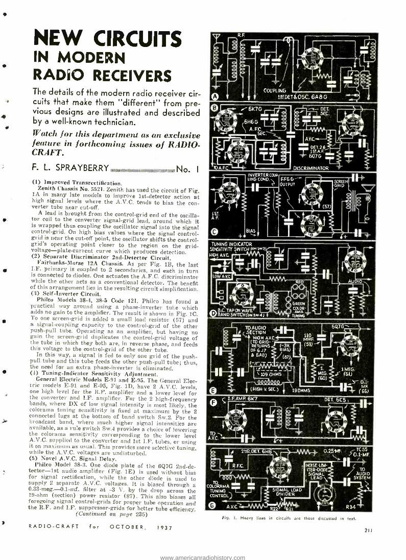
COUPLING
1Y DE b 05C. 6A 8 G
TUNING INDICATOR SENSITIVITY SWITCH 1a+sw2)
HIGH AV .0 .. TUAUDIO ,ILJ SECTION 7
HIGH MC. (TO GRID - RETURNS (-3V. OF6J7 BIAS)
b 6A8) (87)
6Q7G
110 /
MME (59) -.
( HIGH -V. SEC.) 19 OH MS
i
NEW CIRCUITS IN MODERN RADIO RECEIVERS The details of the modern radio receiver cir-
e cuits that make them "different" from pre- vious designs are illustrated and described by a well -known technician. Watch for this department as an exclusive feature in forthcoming issues of RADIO - CRAFT.
F. L. S PRAYB ER RY IIIIIIIIIIIIIIIIIIIIIIIIIIIIIIIIIIIIIIIIIIIIIIIIIIIIIIIIII No. (I) Improved Transrectification.
Zenith Chassis No. 5521. Zenith has used the circuit of Fig. lA in many late models to improve 1st- detector action at high signal levels where the A.V.C. tends to bias the con- verter tube near cut -off. A lead is brought from the control -grid end of the oscilla- for coil to the converter signal -grid lead, around which it
is wrapped thus coupling the oscillator signal into the signal control -grid. On high bias values where the signal control - grid is near the cut -off point, the oscillator shifts the control - grid's operating point closer to the region on the grid - voltage- plate- current curve which produces detection. (2) Separate Discriminator 2nd -Detector Circuit.
Fairbanks -Morse 12A Chassis. As per Fig. 1B, the last I.F. primary is coupled to 2 secondaries, and each in turn is connected to diodes. One actuates the A.F.C. discriminator while the other acts as a conventional detector. The benefit of this arrangement lies in the resulting circuit simplification. (3) Self -Inverter Circuit.
Philco Models 38 -4, 38 -5 Code 121. Philco has found a practical way around using a phase- inverter tube which adds no gain to the amplifier. The result is shown in Fig. 1C. To one screen -grid is added a small load resistor (57) and a signal -coupling capacity to the control -grid of the other push -pull tube. Operating as an amplifier, but having no gain the screen -grid duplicates the control -grid voltage of the tube in which they both are, in reverse phase, and feeds this voltage to the control -grid of the other tube.
In this way, a signal is fed to only one grid of the push - pull tube and this tube feeds the other push -pull tube; thus, the need for an extra phase -inverter is eliminated. (4) Tuning- Indicator Sensitivity Adjustment.
General Electric Models E -91 and E -95. The General Elec- tric models E -91 and E -95, Fig. 1D, have 2 A.V.C. levels, one high level for the R.F. amplifier and a lower level for the converter and I.F. amplifier. For the 2 high- frequency bands, where DX of low signal intensity is most likely, the colorama tuning sensitivity is fixed at maximum by the 2 connected lugs at the bottom of band switch Sw.2. For the broadcast band, where much higher signal intensities are available, as a rule switch Sw.4 provides a choice of lowering the colorama sensitivity corresponding to the lower level A.V.C. supplied to the converter and 1st I.F. tubes, or using it on maximum as usual. This provides more selective tuning, while the A.V.C. voltages are undisturbed. (5) Novel A.V.C. Signal Delay.
Philco Model 38 -3. One diode plate of the 6Q7G 2nd -de- tector -1st audio amplifier (Fig. 1E) is used without bias for signal rectification, while the other diode is used to supply 2 separate A.V.C. voltages. It is biased through a 0.33- meg.- 0.1 -mf. filter at -3 V. by the drop across the 19 -ohm (section) power resistor (87). This also biases all foregoing signal control -grids for proper tube operation and the R.F. and I.F. suppressor -grids for better tube efficiency.
(Continued on page 235)
RADIO -CRAFT for OCTOBER, 1937
TO OLORAMA TUNING CONTROL
DET. 61-16 N.
^aF R.FC.
111
0.25í+1F.
NOISE-LIM- ITER -DIODE SIGNAL
LEAD
Q A.V.C.
SIGNAL LOAD DIVIDER
R22/ rR21
TC 55 55 J M F.
TO AUDIO
SYSTEM
R34
Fig. I. Heavy lines in circuits are those discussed in text.
211
www.americanradiohistory.com
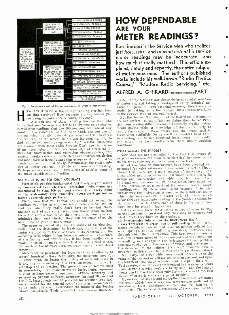
,p) QUANTITY UNDER MEASURE- MENT FLUCTUATING
POSSIBLE ERRORS
WHICH MAY OCCUR IN MEASURE MENTS
WITH ELECTRIC- AL INDICATING INSTRUMENTS
i
INACCURACIES INHERENT IN
THE INSTRUMENT ITSELF
INACCURACIES WHICH HAVE DEVEL-
OPED IN INSTRU- MENT THROUGH ITS USE & HANDLING
INACCURACIES DUE TO WAY
INSTRUMENT IS USED, OR CON- DITIONS UNDER WHICH MEASURE-
MENTS ARE MADE
(a)- SELF-HEATING ERRORS
1
INACCURACIES DUE TO
OBSERVATIONAL ERRORS
(A)- FREQUENCY ERRORS
(r)- WAVEFORM ERRORS
(dl MECHANICAL ERRORS
(e) CALIBRATION ERRORS
(f)- BENT POINTER
(gl- "ZERO" SHIFT
(h) - SPRING ERRORS
IL) - BEARING FRICTION
IjI- ELECTRICAL TROUBLES
(k)MAGNET WEAKENED
III- UNBALANCING
(m)- STRAY MAGNETIC FIELDS
(,I- EXTERNAL TEMP. ERRORS
(0)- INSTRUMENT ALTERS CIRCUIT CONDITIONS
Iqr- POINTER POSITION READ INACCURATELY
Irl- POINTER DEFLECTION FLUCTUATION
Fig. I. Breakdown chart of the various causes of errors in test meters.
HOW ACCURATE is the voltage reading you just took on that receiver? How accurate are the meters you
are using in your service work, anyway? Are you one of those trusting Service Men who
think that just because a meter is fairly new or expensive, it will give readings that are 100 per cent accurate at any point on the scale? Or, on the other hand, are you one of the suspicious but disillusioned type who has tried to check the accuracy of the meters in his test instruments, only to find that no two readings agree exactly? In either case, you (in common with most radio Service Men) are the victim of an incomplete, or inaccurate knowledge of electrical in- strument construction and operating characteristics, for, anyone closely associated with electrical instrument design and manufacture is well aware that errors exist in all instru- ments, and will admit it freely. Fortunately, the entire sub- ject of meter accuracy is fairly simple -and interesting. Perhaps we can clear up, in this series of articles, some of the more troublesome difficulties.
NO METER IS 100 PER CENT ACCURATE
First of all, get thi. fundamental fact firmly in your mind: no commercial type electrical indicating instruments are guaranteed to read 100 per cent correctly at every point on the scale -only very expensive laboratory -type instru- ments approach such perfection.
That means that you cannot, and should not, expect the readings you take on your servicing meters to be 100 per cent accurate. They really don't have to be -but that's another part of our story. What you should know is, how large the errors are, what their origin is, how you can minimize them, and whether they will seriously affect the usefulness of your measurements.
The accuracy, sensitivity, and reliability of an electrical instrument are determined by its design, the quality of the materials used in it, the care taken in its construction, the accuracy with which it has been assembled and calibrated at the factory, and how roughly it has been handled since made. In order to make meters that can be priced within the reach of the average user, accuracy has to be sacrificed somewhat.
Meters can be purchased for from less than a dollar up to several hundred dollars. Naturally, the more one pays for an instrument, the better the quality of materials used in it and the more accuracy and care exercised in its work- manship and calibration. The general run of meters used in present -day high -grade servicing instruments represent a good common -sense compromise between accuracy and price -they provide sufficient accuracy (around 98 per cent for D.C. instruments and 95 per cent for rectifier type A.C. instruments) for the general run of servicing measurements to be made, and are priced within the limits of the Service Man's pocketbook. Their manufacturers deserve unstinted
212
HOW DEPENDABLE ARE YOUR
METER READINGS? Rare indeed is the Service Man who realizes
just hole, why. and to what extent his service meter readings may be inaccurate -and how much it really matters! This article ex-
plains, simply and expertly, the entire subject of meter accuracy. The author's published works include his well -known "Radio Physics
Course," "Modern Radio Servicing," etc.
ALFRED A. GHIRARDI IIIIIIIIIIIIIIIIIIIIIIIIIIIIIIIIIIIII PART
praise, for by working out clever designs, careful selection of materials, and taking advantage of every technical ad- vance and possible manufacturing economy, they have suc- ceeded in making really fine, rugged, instruments available to the Service Man at reasonable cost.
But the Service Man should realize that these instruments are not perfect -no manufacturer claims them to be! Prac- tical construction difficulties make absolutely precise instru- ments unobtainable. A knowledge of the errors likely to occur, the origin of these errors, and the means used to make them negligible (or as small as possible) is of value in enabling one to use electrical instruments intelligently and obtain the best results from them under working conditions.
WHAT CAUSES THE ERRORS?
Now that we are reconciled to the fact that errors do exist in measurements made with electrical instruments, let us see what they are and what may cause them.
All of the common inaccuracies have been grouped and arranged for quick reference in a convenient chart in Fig. 1.
Notice that there are 4 main sources of inaccuracy: (1) those which are inherent in the instrument itself due to its design and construction, and which may be present even in brand new instruments; (2) those which have developed in the instrument as a result of its constant usage, rough handling, etc.; (3) those which occur because of the par- ticular way the instrument is used, or the conditions under which the measurement is made; and, (4) those which occur through inaccurate reading of the pointer position by the observer. In the chart, each of these is further broken down into its contributing causes.
Let us review these contributing causes of error briefly, so that we may understand why they may be present and what effects they have on the readings. (1) Inaccuracies Inherent in the Instrument Itself
(A) Temperature errors due to self -heating. Most instru- ments contain sources of heat, such as moving coils of fine
wire, springs, shunts, multiplier resistors, rectifiers, etc., through which the currents flow. This heat tends to cause a rise in the temperature of the various parts of the instrument -resulting in a change in the resistance of these parts, a consequent change in the current flowing, and a change in
the deflection of the pointer. ( "Carbon" resistors have a negative coefficient and hence -decrease in resistance value.)
Naturally, the error which may result depends upon the value of the current or voltage under measurement and upon the length of time that the instrument is kept in the circuit. Fortunately, since the currents involved in the measurements made in radio service work are fairly small and the instru- ments are kept in the circuit only for a very short time, this source of error is not a very great problem.
By making the shunts and multiplier resistors of resistance materials which have a very low temperature coefficient of
resistance, their resistance change due to heating is
minimized. The increase in resistance of the copper movable
RADIO -CRAFT for OCTOBER, 1937
e
www.americanradiohistory.com
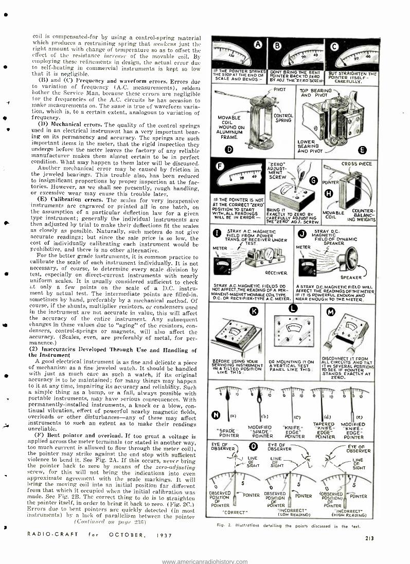
coil is compensated -for by using a control- spring material which produces a restraining spring that weakens just the right amount with change of temperature so as to offset the effect of the resistance increase of the movable coil. By employing these refinements in design, the actual error due to self -heating in commercial instruments is kept so low that it is negligible.
(B) and (C) Frequency and waveform errors. Errors due to variation of frequency (A.C. measurements), seldom bother the Service Man, because these errors are negligible for the frequencies of the A.C. circuits he has occasion to make measurements on. The same is true of waveform varia- tion, which is, to a certain extent, analogous to variation of frequency.
(D) Mechanical errors. The quality of the control springs used in an electrical instrument has a very important bear- ing on its permanency and accuracy. The springs are such important items in the meter, that the rigid inspection they undergo before the meter leaves the factory of any reliable manufacturer makes them almost certain to be in perfect condition. What may happen to them later will be discussed.
Another mechanical error may be caused by friction in the jeweled bearings. This trouble also, has been reduced to insignificant proportions by proper inspection at the fac- tories. However, as we shall see presently, rough handling, or excessive wear may cause this trouble later.
(E) Calibration errors. The scales for very inexpensive instruments are engraved or printed all in one batch, on the assumption of a particular deflection law for a given type instrument; generally the individual instruments are ` then adjusted by trial to make their deflections fit the scales as closely as possible. Naturally, such meters do not give accurate readings; but since the sale price is so low, the cost of individually calibrating each instrument would be prohibitive, and there is no other alternative.
For the better grade instruments, it is common practice to calibrate the scale of each instrument individually. It is not necessary, of course, to determine every scale division by
t test, especially on direct -current instruments with nearly uniform scales. It is usually considered sufficient to check :.t only a few points on the scale of a D.C. instru- ment by actual test. The intermediate points are filled -in, sometimes by hand, preferably by a mechanical method. Of course, if the shunts, multiplier resistors, or condensers used in the instrument are not accurate in value, this will affect the accuracy of the entire instrument. Any subsequent changes in these values due to `raging" of the resistors, con- densers, control -springs or magnets, will also affect the accuracy. (Scales, even, are preferably of metal, for per- manence.) (2) Inaccuracies Developed Through Use and Handling of the Instrument
A good electrical instrument is as fine and delicate a piece of mechanism as a fine jeweled watch. It should be handled with just as much care as such a watch, if its original accuracy is to be maintained; for many things may happen to it at any time, impairing its accuracy and reliability. Such a simple thing as a bump, or a fall, always possible with portable instruments, may have serious consequences. With permanently -installed instruments, a knock or a blow, con- tinual vibration, effect of powerful nearby magnetic fields, overloads or other disturbances -any of these may affect instruments to such an extent as to make their readings unreliable.
(F) Bent pointer and overload. If too great a voltage is applied across the meter terminals (or stated in another way, too much current is allowed to flow through the meter coil), the pointer may strike against the end stop with sufficient violence to bend it. See Fig. 2A. If this occurs, never bring the pointer back to zero by means of the zero -adjusting screw, for this will not bring the indications into even approximate agreement with the scale markings. It will bring the moving coil into an initial position far different from that which it occupied when the initial calibration was made. See Fig. 2B. The correct thing to do is to straighten the pointer itself, in order to bring it back to zero. (Fig. 2C.) Errors due to bent pointers are quickly detected (in most instruments) by a lack of parallelism between the pointer
(Continued on page 236)
RADIO -CRAFT for OCTOBER, 1937
IF THE POINTER STRIKES THE STOP AT THE END OF SCALE AND BENDS'-
DONT BRING POINTER BY ADJ THE
STRAIGHTEN ITSELF
THE -
THE BENT BUT BACKTO ZERO POINTER
ZERO'SCRE CAREFULLY.
.-'
MOVABLE colt
WOUND ON ALUMINUM
FRAME
L O
I
PIVOT
CONTROL SPRING'
TOP BEARING AND PIVOT
0
LOWER BEARING AND PIVOT
-
l'
{ m
U`' E
ZERO" ADJUST- MERE SCREW
/
) /
O --o
....---.° e
- -".--<:: IT ...
TO ZERO BY ADJUSTING
-ZERO" ADJ. SCREW.
....
POIÑTER
MOVABLE COIL
CROSS PIECE y Í
COUNTER - BALANC_
ING WEIGNTS
IF THE POINTER I5 NOT AT THE CORRECT "ZERO"
TO START WITH,ALLREADINGS
WILL BE IN ERROR - BRING EXACTLY CAREFULLY THE
STRAY A.C. MAGNETIC FIELD FROM POWER
TRANS. OF RECEIVER UNDER .j TEST.
METER - f---- -
x RECEIVER
STRAY A.C. MAGNETIC FIELDS DO NOT AFFECT THE READING OF A PER- MANENT- MAGNETMOVABLE COIL TYPE D.C. OR RECTIFIER -TYPE A.C. METER.
STRAY O MAGNETIC FIELD
METER
D.C.
OF DYNAMIC SPEAKER
y
d. v SPEAKER
MAGNETIC FIELD READINGS OFTHE
ENOUGH AND TO THE METER.
WILL METER
cilstzi _ -
A STRAY D.C. AFFECT THE IF IT IS POWERFUL NEAR ENOUGH
©
BEFORE USING YOUR SERVICING INSTRUMENT INA TILTED POSITION
LIKE THIS.
OR A PANEL
O
DISCONNECT IT FROM ALL CIRCUITS AND TILT IT IN SEVERAL POSITIONS TO SEE IF POINTER STANDS EXACTLY AT
ZERO.
.
. 1
MOUNTING IT ON VERTICAL TEST
LIKE THIS:
wPOIN0TER
lo e 1 0
(a) (b)
MODIFIED "SPADE- POINTER
o to o s ro
(d) (e) TAPERED MODIFIED "KNIFE- - KNIFE-
POINTER POINTER
0 5 lo
(C)
- KNIFE-
POINTER
OBSERVER
o OBSERVED POSITION
POINTER
"CORRECT"
O OBSERVER
\I LIFE LINE r. SIGHT SIGHT
S 0
'.--POINTER OBSERVED POSITION
POINTER
\; / /!, .
0
(OBSERVED POSITION)
POINTER
"INCORRECT" (HIGH
VF
LINE
SIGHT
5
POINTER
READING) "INCORRECT" (LOW
b
~POINTER
READING)
Fig. 2. Illustrations detailing the points discussed in the text.
213
www.americanradiohistory.com
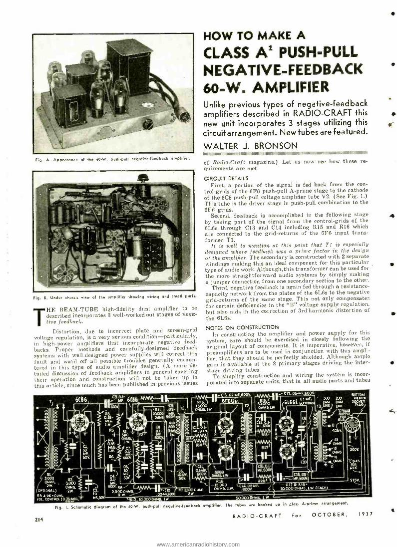
Fig. A. Appearance of the 60 -W. push -pull negative- feedback amplifier.
Fig. B. Under chassis view of the amplifier showing wiring and small parts.
HE BEAM -TUBE high- fidelity dual amplifier to be described incorporates 3 well -worked out stages of nega- tive feedback.
Distortion, due to incorrect plate and screen -grid voltage regulation, is a very serious condition -particularly, in high -power amplifiers that incorporate negative feed- backs. Proper methods and carefully- designed feedback systems with well -designed power supplies will correct this fault and ward off all possible troubles generally encoun- tered in this type of audio amplifier design. (A more de-
tailed discussion of feedback amplifiers in general covering their operation and construction will not be taken up in
this article, since much has been published in previous issues
HOW TO MAKE A
CLASS Al PUSH -PULL NEGATIVE -FEEDBACK 60 -W. AMPLIFIER Unlike previous types of negative- feedback amplifiers described in RADIO -CRAFT this new unit incorporates 3 stages utilizing this circuitarrangement. New tubes are featured.
WALTER J. BRONSON I I I I I I I I I I I I I I I I I I I I I I I I I I I I I I I I I I I I I I I I I I 1 10.111111 I I I I I I I I I I I l l l l l I I I I I I I I I I I I I I I I I I I l l I I I I I I I I I I I I I I I I I I I I I I I I I I I I I I I I I I I I I I I I I I I I I I I I I I I I I I I I I I I I I I I I
of Radio -Craft magazine.) Let us now see how these re- quirements are met.
CIRCUIT DETAILS
First, a portion of the signal is fed back from the con- trol -grids of the 6F6 push -pull A -prime stage to the cathode of the 6C8 push -pull voltage amplifier tube V2. (See Fig. 1.) This tube is the driver stage in push -pull combination to the 6F6 grids.
Second, feedback is accomplished in the following stage by taking part of the signal from the control -grids of the 6L6s through C13 and C14 including R15 and R16 which are connected to the grid- returns of the 6F6 input trans- former Tl.
It is well to mention at this point that TI is especially designed where feedback was a prime factor in the design of the amplifier. The secondary is constructed with 2 separate windings making this an ideal component for this particular type of audio work.Although,this transformer can be used for the more straightforward audio systems by simply making a jumper connection from one secondary section to the other.
Third, negative feedback is again fed through a resistance - capacity network from the plates of the 6L6s to the negative grid- returns of the same stage. This not only compensates for certain deficiencies in the "B" voltage supply regulation, but also aids in the correction of 3rd-harmonic distortion of the 6L6s.
NOTES ON CONSTRUCTION In constructing the amplifier and power supply for this
system, care should be exercised in closely following the original layout of components. It is imperative, however, if preamplifiers are to be used in conjunction with this ampli- fier, that they should be perfectly shielded. Although ample gain is available at the 2 primary stages driving the inter - stage driving tubes.
To simplify construction and wiring the system is incor- porated into separate units, that is, all audio parts and tubes
6C8 G
2W (OPTIONAL)
R2. 3.000 OHMS. 2W
10
VOL L R6 T MF,SOV_
VOL CONTROL G. s.r 0MM5 sw.
Fig. I. Schematic diagram of the 60 -W. push -pull negative -feedback amplifier. The tubes are hooked up In class A -prime arrangement.
RADIO -CRAFT for OCTOBER, 1937
/ c3, MF a1-
6CBG
' 600V l - R3
0.15- MEG. 1 W.
R5
.R4. 0.15' MEG. t.w.
R6 w
C4,
MF, 6001. RB/
2,500 W.
iC13 .02-MF. 600V.
6F .G'6
'R11, 10.000 OHMS
T2
1
50.060 0HM5,1W.
,4 .
BOTTOM ßlMF 500- 200- VIEW OF
6L6GS 60oV pNf) OHM SOCKET
1r
LINE
RIO 500 DIMS,
1W.
Ri
-05, la MF., SOY.
CIO .020W
1011, O.SMF, 600V.
C16.0.1-
C1B.05-
R22.500 OHMS, 2W.
-15,000 OHMS, 1
/ R20, kC14:02.MF R17 RIB-
600V
50.000 014145
10.000 OHMS. 1.W. (EACH)
/15 OHMS
OHMS
4 DIMS
o
x x ^ 300V
C BIAS WR 6F6
275V.
214
4
ff
l
www.americanradiohistory.com
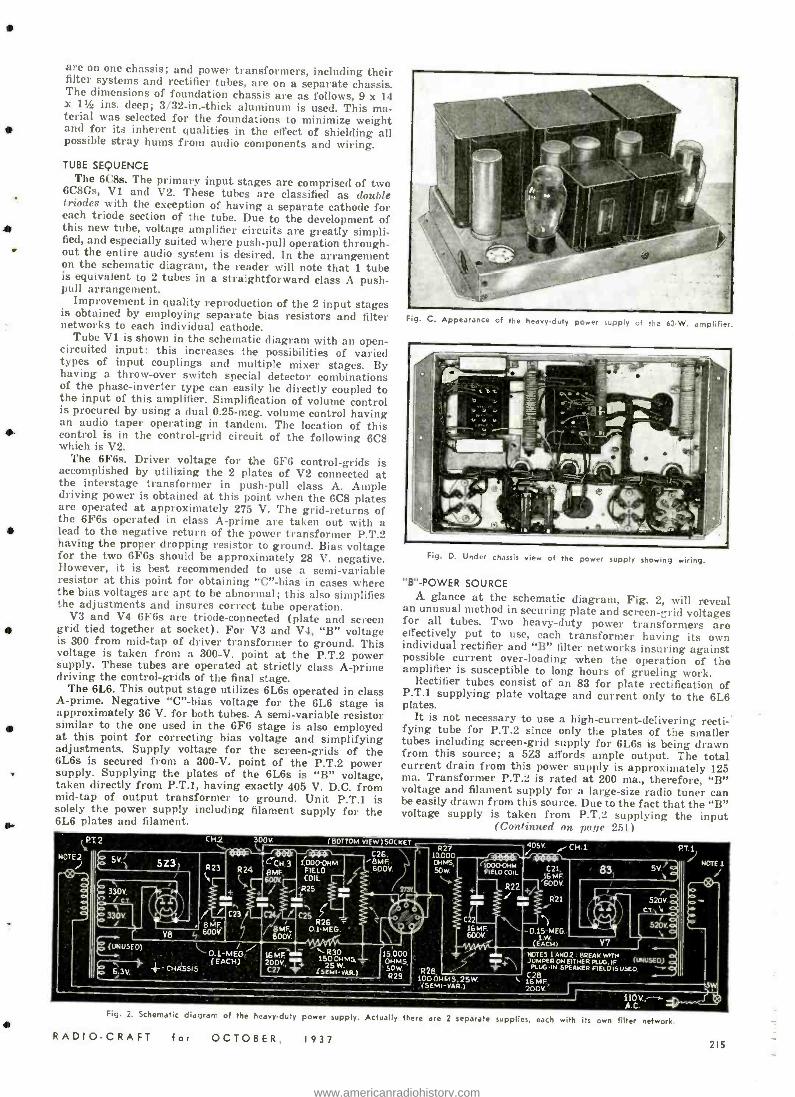
are on one chassis; and power transformers, including their filter systems and rectifier tubes, are on a separate chassis. The dimensions of foundation chassis are as follows, 9 x 14 x 1% ins. deep; 3/32 -in. -thick aluminum is used. This ma- terial was selected for the foundations to minimize weight and for its inherent qualities in the effect of shielding all possible stray hums from audio components and wiring.
TUBE SEQUENCE The 6C8s. The primary input stages are comprised of two
6C8Gs, V1 and V2. These tubes are classified as double triodes with the exception of having a separate cathode for each triode section of the tube. Due to the development of S this new tube, voltage amplifier circuits are greatly simpli- fied, and especially suited where push -pull operation through- out the entire audio system is desired. In the arrangement on the schematic diagram, the reader will note that 1 tube is equivalent to 2 tubes in a straightforward class A push - pull arrangement.
Improvement in quality reproduction of the 2 input stages is obtained by employing separate bias resistors and filter networks to each individual cathode.
Tube V1 is shown in the schematic diagram with an open - circuited input: this increases the possibilities of varied types of input couplings and multiple mixer stages. By having a throw -over switch special detector combinations of the phase- inverter type can easily be directly coupled to the input of this amplifier. Simplification of volume control is procured by using a dual 0.25 -meg. volume control having an audio taper operating in tandem. The location of this control is in the control -grid circuit of the following 6C8 which is V2.
The 6F6s. Driver voltage for the 6F6 control -grids is accomplished by utilizing the 2 plates of V2 connected at the interstage transformer in push -pull class A. Ample driving power is obtained at this point when the 6C8 plates are operated at approximately 275 V. The grid -returns of the 6F6s operated in class A -prime are taken out with a lead to the negative return of the power transformer P.T.2 having the proper dropping resistor to ground. Bias voltage for the two 6F6s should be approximately 28 V. negative. However, it is best recommended to use a semi -variable resistor at this point for obtaining "C" -bias in cases where the bias voltages are apt to be abnormal; this also simplifies the adjustments and insures correct tube operation.
V3 and V4 6F6s are triode- connected (plate and screen grid tied together at socket). For V3 and V4, "B" voltage is 300 from mid -tap of driver transformer to ground. This voltage is taken from a 300 -V. point at the P.T.2 power supply. These tubes are operated at strictly class A -prime driving the control -grids of the final stage.
The 6L6. This output stage utilizes 6L6s operated in class A- prime. Negative "C" -bias voltage for the 6L6 stage is approximately 36 V. for both tubes. A semi -variable resistor similar to the one used in the 6F6 stage is also employed at this point for correcting bias voltage and simplifying adjustments. Supply voltage for the screen -grids of the 6L6s is secured from a 300 -V. point of the P.T.2 power supply. Supplying the plates of the 6L6s is "B" voltage, taken directly from P.T.1, having exactly 405 V. D.C. from mid -tap of output transformer to ground. Unit P.T.1 is solely the power supply including filament supply for the 6L6 plates and filament.
Fig. C. Appearance of the heavduty power supply of th;
Fig. D. Under chassis view of the power supply showing wiring.
"B" -POWER SOURCE A glance at the schematic diagram, Fig. 2, will reveal an unusual method in securing plate and screen -;rid voltages for all tubes. Two heavy -duty power transformers are
effectively put to use, each transformer having its own individual rectifier and "B" filter networks insuring against possible current over -loading when the operation of the amplifier is susceptible to long hours of grueling work.
Rectifier tubes consist of an 83 for plate rectification of P.T.1 supplying plate voltage and current only to the 6L6 plates.
It is not necessary to use a high- current -delivering recti -' fying tube for P.T.2 since only the plates of the smaller tubes including screen -grid supply for 6L6s is being drawn from this source; a 5Z3 affords ample output. The total current drain from this power supply is approximately 125 ma. Transformer P.T.2 is rated at 200 ma., therefore, "B" voltage and filament supply for a large -size radio tuner can be easily drawn from this source. Due to the fact that the "B" voltage supply is taken from P.T.2 supplying the input
(Continued one page 251)
NOTE2 sV'
33DV. / c.
330v /
5Z3) R23
rOV. (BOTTOM VIEW)SOCKET
7.
R24 CCH.g (.000-011m BMF, COIL - 600V
4 R25 e _
C23/ C24 C25 R26 7
7 MF 0.1-6166. 600V. V8
8 MF. tr, 600V.
C26. BMF.
600V.
(UNUSED) I. / 0.1 -MEG.
o . Il` (EACH) 4. 6.3V.' CHASSIS
16MF 200V., C27 T
1500 MS, 25 W.
(SEMI-VAR.1
15,000 OHMS, SOW P29
R27 10.000 OHMS,
" í000011M 50w FIELD COIL
R28. 100OHM5.25W (SEMI -VAR.I
R22
405V. CH .1
C21, 16 MF
'600V.
R21
0.15-MEG. I W.
(EACH)
831 5V c 1 .
V7 NOTES 1AND2. BREAKW"H
(IMUSEO) 5 +\ JUMRER ON EITHER FLUG. IF - VLUGIN SPEAKER FIELOISUSED. C28
I- 16 ME 200V' I
110V,-
pTl J
NOTE 1
LSW
Fig. 2. Schematic diagram of the heavy -duty power supply. Actually there are 2 separate supplies, each with its own filter network.
RADIO -CRAFT for OCTOBER, 1937 215
www.americanradiohistory.com
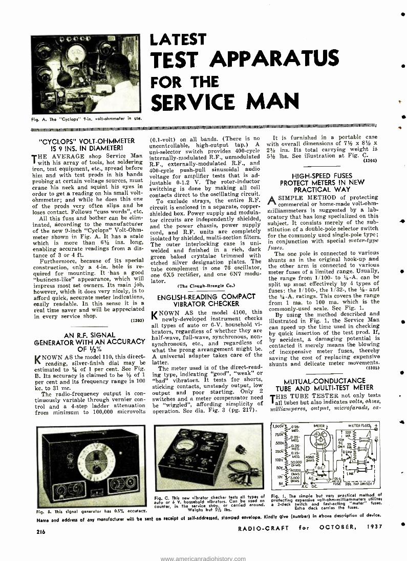
LATEST
TEST APPARATUS FOR THE
SERVICE MAN Fig. A. The "Cyclops" 9 -in. volt- ohmmeter in use.
"CYCLOPS" VOLT -OHMMETER (0.1 -volt) on all bands. (There is no It is furnished in a portable case
IS 9 INS. IN DIAMETER! uncontrollable, high -output tap.) A with overall dimensions of 711a x 8112 x
uni- selector switch provides 400 -cycle 21/2 ins. Its total carrying weight is THE AVERAGE shop Service Man internally- modulated R.F., unmodulated 514 lbs. See illustration at Fig. C.
with his array of tools, hot soldering R.F., externally- modulated R.F., and (1384)
iron, test equipment, etc., spread before 400 -cycle push -pull sinusoidal audio him and with test prods in his hands voltage for amplifier tests that is ad- HIGH -SPEED FUSES probing at certain voltage sources, must justable 0 -1.2 V. The rotor -inductor PROTECT METERS IN NEW crane his neck and squint his eyes in switching is done by making all coil PRACTICAL WAY order to get a reading on his small volt- contacts direct to the oscillating circuit. ohmmeter; and while he does this one To exclude strays, the entire R.F. A SIMPLE METHOD of protecting of the prods very often slips and he circuit is enclosed in a separate, copper- commercial or home -made volt -ohm-
loses contact. Follows "cuss words", etc. shielded box. Power supply and module- milliammeters is suggested by a lab -
All this fuss and bother can be elim- for circuits are independently shielded, oratory that has long specialized on this mated, according to the manufacturer and the power chassis, power supply subject. It consists merely of the sub- 4 of the new 9 -inch "Cyclops" Volt -Ohm- cord, and R.F. units are completely stitution of a double -pole selector switch meter shown in Fig. A. It has a scale isolated by shielded, multi -section filters, for the commonly used single -pole type; which is more than 61/z ins. long, The outer interlocking case is uni- in conjunction with special 9neter -type enabling accurate readings from a dis- welded and finished in a rich, dark fuses. tance of 3 or 4 ft. green baked crystalac trimmed with The one pole is connected to various
Furthermore, because of its special etched silver designation plates. The shunts as in the original hook -up and construction, only a 4 -in. hole is re- tube complement is one 76 oscillator, the other arm is connected to various quired for mounting. It has a good one 6X5 rectifier, and one 6N7 modu- meter fuses of a limited range. Usually, "business -like" appearance, which will lator. the range from 1 /100- to 14-A. can be
impress most set owners. Its main job, (The Clough- Brendle Co.) split up most effectively by 4 types of however, which it does very nicely, is to fuses: the 1 /100 -, the 1/32 -, the 1/a- and afford quick, accurate meter indications, ENGLISH- READING COMPACT the 14 -A. ratings. This covers the range easily readable. In this sense it is a VIBRATOR CHECKER from 1 ma. to 100 ma. which is the real time saver and will be appreciated commonly -used scale. See Fig. 1.
KNOWN AS the model 4100, this in every service shop.
(1303) newly- developed instrument checks By using the method described and
all types of auto or 6 -V. household vi- illustrated in Fig. 1, the Service Man
brators, regardless of whether they are can speed up the time used in checking
AN R.F. SIGNAL half -wave, full -wave, synchronous, non- by quick insertion of the test prod. If,
GENERATOR WITH AN ACCURACY synchronous, etc., and regardless of by accident, a damaging potential is
OF 1/2% what the prong arrangement might be. contacted it merely means the blowing of inexpensive meter fuses, thereby
KNOWN AS the model 110, this
may A universal adapter takes care of the saving the cost of replacing expensive
reading, silver -finish diel may be latter. shunts and delicate meter movements. estimated to 1/a of 1 per cent. See Fig. The meter used is of the direct -read- (1385)
B. Its accuracy is claimed to be 1/2 of 1 ing type, indicating "good", "weak" or
per cent and its frequency range is 100 "bad" vibrators. It tests for shorts, MUTUAL -CONDUCTANCE kc. to 31 mc. sticking contacts, unsteady output, low
TUBE AND MULTI -TEST METER The radio- frequency output is con- output and poor starting. Only 2
tinuously variable through vernier con- switches and a meter compensator need THIS TUBE TESTER not only tests
trol and a 4 -step ladder attenuation be "wiggled ", affording simplicity of all tubes but also indicates volts, ohms,
from minimum to 100,000 microvolts operation. See dia. Fig. 3 (pg. 217). nlilliamlperes, output, mnicrofarads, ca-
A
Fig. B. This signal generator has 0.5% accuracy.
Name and address of any manufacturer will be sent on receipt of self -addressed.
Fig. C. This new vibrator checker tests all types of
auto or 6 V. household vibrators. Can be used on
counter, in the service shop, or carried around. Weighs but 51/2 lbs.
stamped envelope. Kindly give (number) in above description of device.
RADIO -CRAFT for OCTOBER, 1937
1.00o(
750
500V
250v.
t00V'
50v._
5V
0.25. MEG.
MEG
0-25 MEG.
0.15- ' MEG.
p080 40.000
OMMS 5.000 OMMS
METER ) METER FUSE51 +
A el .
Ic0.C.1 I `- ==1r 1MÁ
A.C. MerA I
'6L. TAP SWITCH 1 ..f
f1SÉ D A.l: aC
Fig. I. The simple but very practical method of protecting expensive volt- ohm -milliammeters utilizes a 2 -deck switch and fast -acting "meter" fuses.
Extra deck carries the fuses.
216
www.americanradiohistory.com
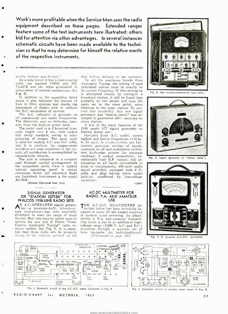
4
Work's more profitable when the Service Man uses the radio equipment described on these pages. Extended ranges feature some of the test instruments here illustrated; others bid for attention via other advantages. In several instances schematic circuits have been made available to the techni- cian so that he may determine for himself the relative merits of the respective instruments.
I I I ::1111111111111111II I I I111111111111111111IIf 1111i11111I1I111111111111111111:f IIIIIIIIIIIIIIIIIIII1l111111111111i1111111111111111111111111111111911111111111111111111D1111111111111011111111111111111111
parity, leakage and deribelr! As a tube tester it has a dual -reading
scale, one marked POOR and RE- PLACE and the other graduated in micro -ohms of mutual conductance. See Fig. D.
In addition to the quantities listed above it also indicates the amount of hum in filter systems and checks the inductance of chokes with or without the D.C. component of current.
The A.C. voltmeter is accurate on all commercial and audio frequencies. The ohmmeter uses no batteries, oper- ates from the built -in power pack.
The meter used is a d'Arsonval type, scale length ever 4 ins., with etched dial easily readable, owing to color grouping of ranges. The sanie scale is used for reading A.C. and D.C. volts, and it is uniform. No copper -oxide rectifiers are used anywhere in the cir- cuit; all rectification is accomplished by vacuum -tube circuits.
The unit is contained in a compact case through careful arrangement of the component parts. Case is rubbed walnut, operating panel is etched chromium finish. All necessary leads are furnished. Instrument is the model AC -51X.
(Hickok Electrical Inst. Co.)
SIGNAL GENERATOR OR "STATION SETTER" FOR
PHILCOS 1938 -LINE RADIO SETS AN A.C.-OPERATED signal genera -
tor-a precision- built, laboratory - type instrument -has been especially developed to meet the needs of those Service Men who may be called upon to service the new line of Philco "Cone - Centric Automatic Tuning" radio re- ceiver models. See Fig. E. It is essen- tial that these radio sets be properly set -up to the stations printed on the
dial, before delivery to the customer. To get the maximum benefit from
Automatic Tuning, the setting of each individual station must be exactly on its correct frequency. If this setting -up is attempted simply by tuning -in a broadcast station, it will be found that probably no two people will tune the radio set to the same point, when listening to the same station. To pre- vent this possibility, this new signal generator and "station setter" was de- veloped to guarantee 100% accuracy on every station.
A few of the many features of the 1938 model 077 signal generator or Station Setter are:
Operates from A.C. outlet; covers highest and lowest frequencies (115 kc. to 37 mc.), in fundamentals, not har- monics; generous overlap of bands: combined on -off and modulation switch; new knife -edge pointer for accurate readings; 3 output connections; ex- ceptionally high R.F. output; full at- tenuation on all bands controllable in steps or continuously; 400 -cycle audio signal provided; equipped with 6 ft .
cable and plug having extra outlet built -in; unaffected by line- voltagt variations.
(1306)
AC -DC MULTIMETER FOR RADIO, P.A. AND AMATEUR
USE
T11 A.C.-D.C. MULTIMETER de- scribed below has been primarily de-
signed to cover all the ranges required in modern radio servicing. Its adapt- ability to P.A. and amateur transmit- ting needs is due to an additional high - voltage range (2,500 V. A.C. and D.C.) accessible through a separate set of twin tip -jacks. An individually -cali-
(Continued on paye 246)
21.74 / OHMS
166.66" OHM5
5.000 - OHMS
400MA 100 MV
DC 9.90D OHMS)
-DC C-WW,A
`A C. 9.500 00 M5
0.10725 MEG -z. 9.800 01045 -L
o 0 0 0 0 0 00 o 0 15.000 4 i OHM5
o o 0 0 0 0 00 o o- 9500...'5 4.SVT = i =
1.5- l f 10MA LOW 01.445 t \ OHMS
0 OHMS j
0.5- 40 OHM OHMS
1wú°s
10V. 50V 250V. 1.000V 1 AMP SOMA 2500 / 2594M /
'(0.2. 6)75 - 7
MEG. MEG Ç
O TEST +
L. RECTIFIER
I 1.5 MEGS
40.000 -® 01445 -2500V}
Fig. 1. Schematic circuit of the A.C. -D.C. meter illustrated in Fig. F.
RADIO -CRAFT for OCTOBER, 1937
Fig. D. New mutual . conducfa -ce tube tester.
Fig. E. Signal generator or "station setter ".
Fig. F. A universal A.C.-D.C. multimeter.
PAD i6 tST
.4
.LOrE Em II3at I
t-1 IL 50 eF O
.
t11111 tt\ t A '10.000
OHMS
A. E. ADAPTERS
Fig. 3 Schematic circuit of vibrator tester shown in Fig. C.
217
www.americanradiohistory.com
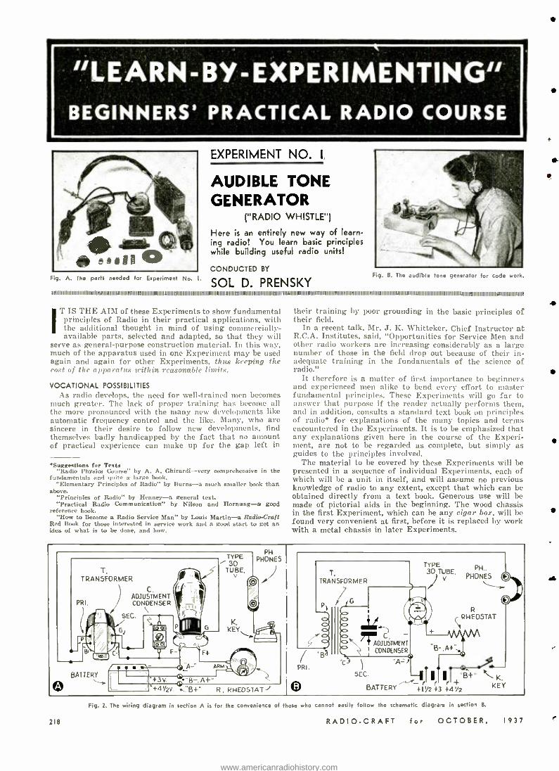
"LEARN -BY- EXPERIMENTING" BEGINNERS' PRACTICAL RADIO COURSE
Fig. A. The parts needed for Experiment No.
EXPERIMENT NO.
AUDIBLE TONE GENERATOR
( "RADIO WHISTLE ")
Here is an entirely new way of learn- ing radio! You learn basic principles while building useful radio units!
CONDUCTED BY
SOL D. PRENSKY Fig. B. The audible tone generator for code work.
IT IS THE AIM of these Experiments to show fundamental principles of Radio in their practical applications, with the additional thought in mind of using commercially - available parts, selected and adapted, so that they will
serve as general -purpose construction material. In this way, much of the apparatus used in one Experiment may be used again and again for other Experiments, thus keeping the cost of the apparatus within reasonable limits.
VOCATIONAL POSSIBILITIES As radio develops, the need for well -trained men becomes
much greater. The lack of proper training has become all the more pronounced with the many new developments like automatic frequency control and the like. Many, who are sincere in their desire to follow new developments, find themselves badly handicapped by the fact that no amount of practical experience can make up for the gap left in
Saggeslions for Texte "Radio Physics Course" by A. A. Chirardi -very comprehensive in the
fundamentals and quite a large book. "Elementary Principles of Radio" by Burns -a much smaller book than
above. "Principles of Radio" by Henney -a general text. "Practical Radio Communication" by Nilson and Hornung -a good
reference book. "How to Become a Radio Service Man" by Louis Martin -a Radio -Craft
Red Book for those interested in service work and a good start to get an idea of what is to be done. and how.
their training by poor grounding in the basic principles of their field.
In a recent talk, Mr. J. K. Whitteker, Chief Instructor at R.C.A. Institutes, said, "Opportunities for Service Men and other radio workers are increasing considerably as a large number of those in the field drop out because of their in- adequate training in the fundamentals of the science of radio."
It therefore is a matter of first importance to beginners and experienced men alike to bend every effort to master fundamental principles. These Experiments will go far to answer that purpose if the reader actually performs them, and in addition, consults a standard text book on principles of radio* for explanations of the many topics and terms encountered in the Experiments. It is to be emphasized that any explanations given here in the course of the Experi- ment, are not to be regarded as complete, but simply as guides to the principles involved.
The material to be covered by these Experiments will be presented in a sequence of individual Experiments, each of which will be a unit in itself, and will assume no previous knowledge of radio to any extent, except that which can be obtained directly from a text book. Generous use will be made of pictorial aids in the beginning. The wood chassis in the first Experiment, which can be any cigar box, will be found very convenient at first, before it is replaced by work with a metal chassis in later Experiments.
T, TRANSFORMER
TYPE 30
TUBE. v T.
TRANSFORMER
1G C. STMENT
CONDENSER
SEC.
Pi
TYPE PH
PHONES
"B-A+
R, RHEOSTAT
Cp
SEC.
R RHEOSTAT
0
o
K.
BATTERY +1%2 +3 +4%2 KEY
218
Fig. 2. The wiring diagram in section A is for the convenience of those who cannot easily follow the schematic diagram in section B.
RADIO -CRAFT for OCTOBER, 1937
i
www.americanradiohistory.com
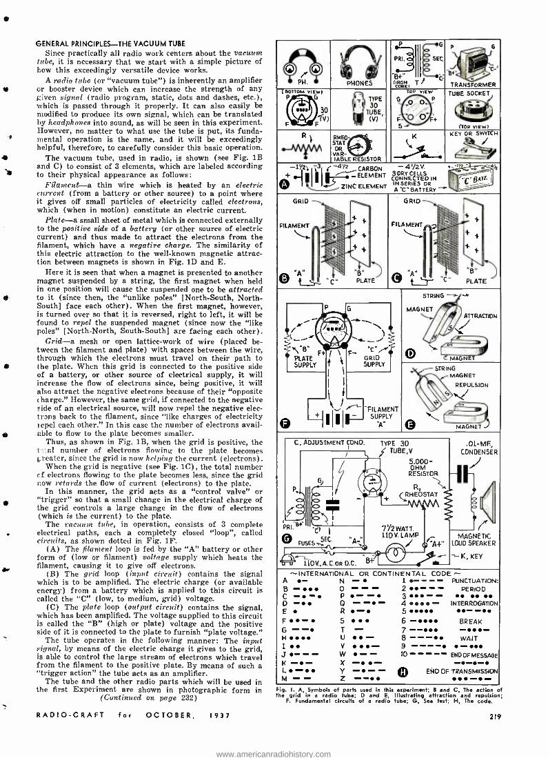
-f
GENERAL PRINCIPLES -THE VACUUM TUBE
Since practically all radio work centers about the vacuum tube, it is necessary that we start with a simple picture of how this exceedingly versatile device works.
A radio tube (or "vacuum tube ") is inherently an amplifier or booster device which can increase the strength of any given signal (radio program, static, dots and dashes, etc.), which is passed through it properly. It can also easily be modified to produce its own signal, which can be translated by headphones into sound, as will be seen in this experiment. However, no matter to what use the tube is put, its funda- mental operation is the same, and it will be exceedingly helpful, therefore, to carefully consider this basic operation.
1 The vacuum tube, used in radio, is shown (see Fig. 1B and C) to consist of 3 elements, which are labeled according to their physical appearance as follows:
Filament -a thin wire which is heated by an electric current (from a battery or other source) to a point where it gives off small particles of electricity called electrons, which (when in motion) constitute an electric current.
Plate -a small sheet of metal which is connected externally to the positive side of a battery (or other source of electric current) and thus made to attract the electrons from the filament, which have a negative charge. The similarity of this electric attraction to the well -known magnetic attrac- tion between magnets is shown in Fig. 1D and E.
Here it is seen that when a magnet is presented to another magnet suspended by a string, the first magnet when held in one position will cause the suspended one to be attracted to it (since then, the "unlike poles" [North -South, North - South] face each other). When the first magnet, however, is turned over so that it is reversed, right to left, it will be found to repel the suspended magnet (since now the `like poles" [North- North, South -South] are facing each other).
Grid -a mesh or open lattice -work of wire (placed be- tween the filament and plate) with spaces between the wire, through which the electrons must travel on their path to the plate. When this grid is connected to the positive side of a battery, or other source of electrical supply, it will increase the flow of electrons since, being positive, it will also attract the negative electrons because of their "opposite charge." However, the same grid, if connected to the negative side of an electrical source, will now repel the negative elec- trons back to the filament, since "like charges of electricity repel each other." In this case the number of electrons avail - able to flow to the plate becomes smaller.
Thus, as shown in Fig. 1B, when the grid is positive, the t'T al number of electrons flowing to the plate becomes greater, since the grid is now helping the current (electrons).
When the grid is negative (see Fig. 1C), the total number cf electrons flowing to the plate becomes less, since the grid now retards the flow of current (electrons) to the plate.
In this manner, the grid acts as a "control valve" or "trigger" so that a small change in the electrical charge of the grid controls a large change in the flow of electrons (which is the current) to the plate.
The vacuum tube, in operation, consists of 3 complete electrical paths, each a completely closed "loop ", called circuits, as shown dotted in Fig. 1F.
(A) The filament loop is fed by the "A" battery or other form of (low or filament) voltage supply which heats the
410, filament, causing it to give off electrons.
(B) The grid loop (input circuit) contains the signal which is to be amplified. The electric charge (or available energy) from a battery which is applied to this circuit is called the "C" (low, to medium, grid) voltage.
(C) The plate loop (output circuit) contains the signal, which has been amplified. The voltage supplied to this circuit is called the "B" (high or plate) voltage and the positive side of it is connected to the plate to furnish "plate voltage."
The tube operates in the following manner: The input signal, by means of the electric charge it gives to the grid, is able to control the large stream of electrons which travel from the filament to the positive plate. By means of such a "trigger action" the tube acts as an amplifier.
The tube and the other radio parts which will be used in the first Experiment are shown in photographic form in
(Continued on page 232)
RADIO -CRAFT for OCTOBER. 1937
IV
O J. O PH.
` I,Y/IV lV/ PHONES
P
(IRON COREI
SEC
..il+. C T
p G
C-
TRANSFORMER (BOTTOM VIEW)
G
F F
T. TYPE
BE
TOO viEw
:;: S-,
TUBE SOCKET
(TOO VIEW)
)STO- HA Aw Á DR
R- IABLE RESISTOR . KEY OR SWiT CH
/
11 1 13 i --4Y2 CARBON - 41/2V. t 11111 ELEMENT 3ORYCELLS
O CONNECTED IN i` .ZINCELEMENT INSERIES OR
-C-
''_ h s4h tIATL
C - - A BATTERY
GRID
FILAMENT
;I
fl
,
'.
' 'i
11 W,
PLATE
GRID
FILAMENT
O '-r.
^ l ii . 'C'
n
11
i¡i?
i
11 PLATE
STRING .- MAGNET
ATTRACTION
O MAGNET
/r' ..f..\
LATE SUPPLY
).a)\ F+
P
Ja i \
}
I
I I
G
F- GRID SUPPLY
` STRING
t MAGNET
REPULSION I + I
..I r` - II -
FILAMENT SUPPLY fJ ©
MAGNET
C, ADJUSTMENT CONO. TYPE 30 TUBE,V
.01-MF, CONDENSER f
G
l j 5,000- OHM
RESISTOR
IN (RHEOSTAT R
(RHEÓSTAT
I\AV\A T f (fi PRl.sï Cf il
O ;MS SEC' -A' 7I2WATT. 110V. LAMP / firm-
MAGNETIC LOUD SPEAKER t K, KEY ~ rZ
110V.,A..oa O.C. B+
--INTERNATIONAL OR CONTINENTAL CODE ^- A .- N .... 1. 0-- -- PUNCTUATION: B - O - - 2--- PERIOD C - - P - - 3-- D - Q - -- 4 - INTERROGATION
E R - 5 -- F- 5 6- BREAK G - - T - 7 -- -- H.. U - 8 - - - WAIT I V - 9 ---- - J - - - W - - 10 ENDOFMESSAGE K-- X - - --- L - Y - - - © EÑD OF TRANSMISSION M - - Z --
Hg. I. A, Symbols of parts used in this experiment; If and C, The action of he grid in a radio tube; D and E, Illustrating attraction and repulsion;
F. Fundamental circuits of a radio tube; G, S text; H, The code.
219
www.americanradiohistory.com
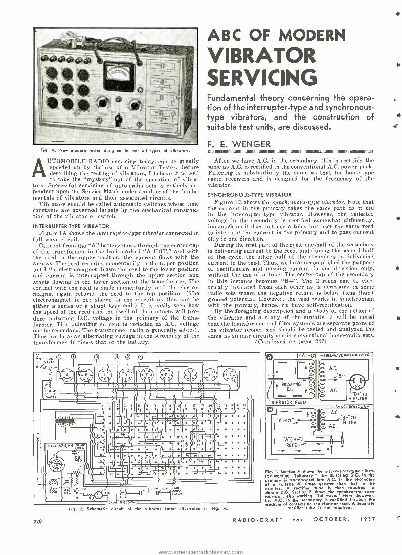
Fig. A. New modern tester des4:ed to test all types of vibrators.
AUTOMOBILE -RADIO servicing today, can be greatly speeded up by the use of a Vibrator Tester. Before describing the testing of vibrators, I believe it is well to take the "mystery" out of the operation of vibra-
tors. Successful servicing of auto -radio sets is entirely de- pendent upon the Service Man's understanding of the funda- mentals of vibrators and their associated circuits.
Vibrators should be called automatic switches whose time constants are governed largely by the mechanical construc- tion of the vibrator or switch.
INTERRUPTER -TYPE VIBRATOR Figure IA shows the interrupter -type vibrator connected in
full -wave circuit. Current from the "A" battery flows through the center -tap
of the transformer in the lead marked "A HOT," and with the reed in the upper position, the current flows with the arrows. The reed remains momentarily in the upper position until ti-e electromagnet draws the reed to the lower position and current is interrupted through the upper section and starts flowing in the lower section of the transformer. The contact with the reed is made momentarily until the electro- magnet again returns the reed to the top position. (The electromagnet is not shown in the circuit as this can be either a series or a shunt type coil.) It is easily seen how the speed of the reed and the dwell of the contacts will pro- duce pulsating D.C. voltage in the primary of the trans- former. This pulsating current is reflected as A.C. voltage on the secondary. The transformer ratio is generally 40 -to -1. Thus, we have an alternating voltage in the secondary of the transformer 40 times that of the battery.
ABC OF MODERN
VIBRATOR SERVICING Fundamental theory concerning the opera- tion of the interrupter -type and synchronous - type vibrators, and the construction of suitable test units, are discussed.
F. E. WENGER 11111111111111111111111111111111111I I I n 111111111111111111111111111111111111111011111111111111111111111111111111111111111111111111111101111111111111
After we have A.C. in the secondary, this is rectified the same as A.C. is rectified in the conventional A.C. power pack. Filtering is substantially the same as that for home-type radio receivers and is designed for the frequency of the vibrator.
SYNCHRONOUS -TYPE VIBRATOR Figure 1B shows the synchronous -type vibrator. Note that
the current in the primary takes the same path as it did in the interrupter -type vibrator. However, the reflected voltage in the secondary is rectified somewhat differently, inasmuch as it does not use a tube, but uses the same reed to interrupt the current in the primary and to pass current only in one direction.
During the first part of the cycle one -half of the secondary is delivering current to the reed, and during the second half of the cycle, the other half of the secondary is delivering current to the reed. Thus, we have accomplished the purpose of rectification and passing current in one direction only, without the use of a tube. The center -tap of the secondary in this instance becomes "B± ". The 2 reeds can be elec- trically insulated from each other as is necessary in some radio sets where the negative return is below (less than) ground potential. However, the reed works in synchronism with the primary, hence, we have self- rectification.
By the foregoing description and a study of the action of the vibrator and a study of the circuits, it will be noted that the transformer and filter systems are separate parts of the vibrator proper and should be tested and analyzed the same as similar circuits are in conventional home -radio sets.
(Continued on page 247)
O © fB o fj t ÌIiI.i [[[ «ecess cj « "_ t-` 5 liiR[[
.yyrr cecictczáz=etc` A Stf
-
ar a Qi 1 T«
l c r__wetitIO I
dQ(al QQQ[iI`' ({ B¡[f
il(tZL. ad `1`zizc.. r[ QT .(Í. . .
etc 624, 842o1or.
f
5.000 OAMS i
B1F. SOOV.
O .0I-MF 2.000V
(CCM)
t_ _CAUe.9S00oMMS
.. rig. 2. Schematic circuit of the vibrator tester illustrated in Fig. A.
220
.A HOT - FULL-WAVE INTERRUPTER-
PULSATING
D.C. f "B +' TO FILTER
VIBRATOR REED
AC. ---.B+" TO
FILTER
A lB ) REED -
Fig. I. Section A shows the interrupter -type vibra- tor working "full- wave.' The pulsating D.C. in the primary is transformed into A.C. in the secondary at a voltage 40 times greater than that in the primary. A rectifier tube is then required to obtain D.C. Section B shows the wlnlehronous -type vibrator, also working "full- wave." Here, however, the A.C. in the secondary is rectified through the medium of contacts on the vibrator reed. A separate
rectifier tube is not required.
RADIO -CRAFT for OCTOBER, 1937
Y
.f
0
www.americanradiohistory.com
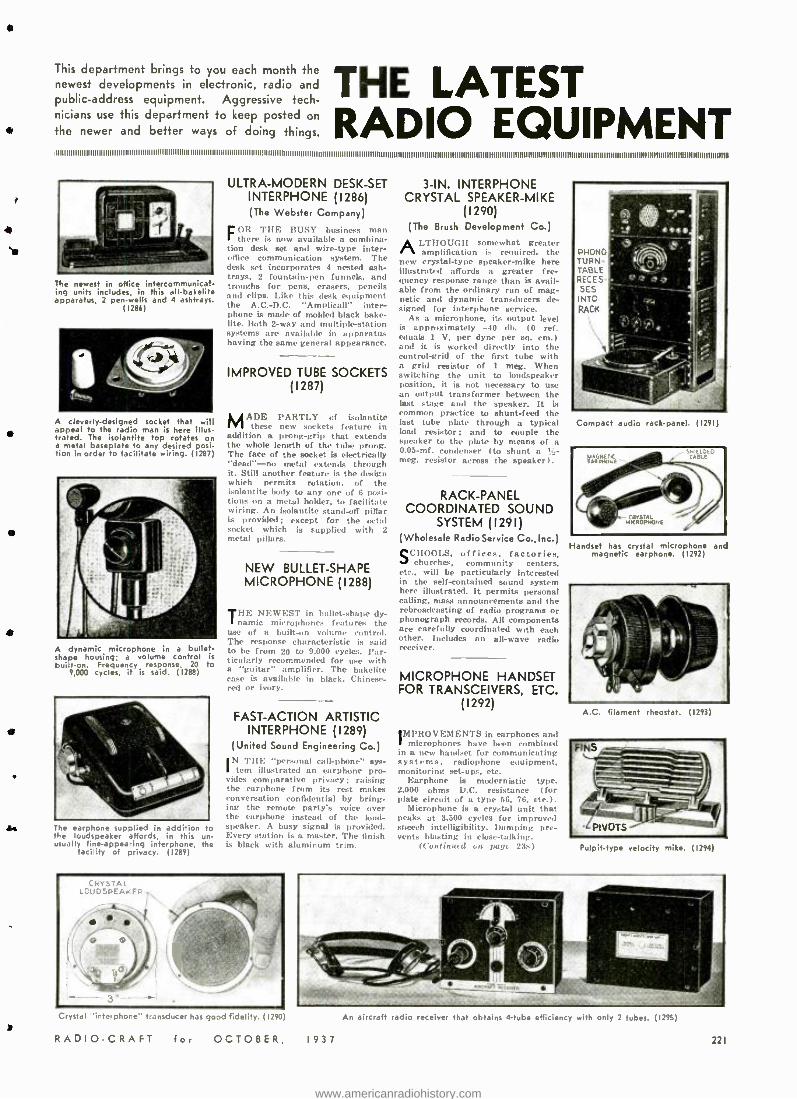
This department brings to you each month the newest developments in electronic, radio and public- address equipment. Aggressive tech- nicians use this department to keep posted on
+ the newer and better ways of doing things.
t
4 's
e
THE LATEST RADIO EQUIPMENT
@
The newest in office intercommunicat - ing units includes, in this all -bakelite apparatus, 2 pen -wells and 4 ashtrays.
(1286)
A cleverly- designed socket that will appeal to the radio man is here illus- trated. The isolantite top rotates on a metal baseplate to any desired posi- tion in order to facilitate wiring. (1287)
A dynamic microphone in a bullets shape housing; a volume control is built -on. Frequency response, 20 to
9,000 cycles, it is said. (1288)
The earphone supplied in addition o the loudspeaker affords, in this u - usually fine- appearing interphone, t e
facility of privacy. (1289)
ULTRA -MODERN DESK -SET INTERPHONE (1286) (The Webster Company)
FOR THE BUSY business man there is now available a combina-
tion desk set and wire-type inter- office communication system. The desk set incorporates 4 nested ash- trays, 2 fountain -pen funnels, and troughs for pens, erasers, pencils and clips. Like this desk equipment the A.C. -D.C. "Amplicall" inter- phone is made of molded black bake- lite. Both 2 -way and multiple- station systems are available in apparatus having the same general appearance.
IMPROVED TUBE SOCKETS (1287)
MADE PARTLY of isolantite these new sockets feature in
addition a prong -grip that extends the whole length of the tube prong. The face of the socket is electrically "dead " -no metal extends through !r. Still another feature is the design
hich permits rotation, of the .ilantite body to any one of C. posi-
tions on a metal holder, to facilitate wiring. An isolantite stand -off pillar is provided; except for the octal socket which is supplied with 2 metal pillars.
NEW BULLET -SHAPE MICROPHONE (1288)
THE NEWEST in bullet -shape dy- namic microphones features the
-e of a built -on volume control. The response characteristic is said to be from 20 to 9,000 cycles. Par- ticularly recommended for use with a "guitar" amplifier. The bakelite case is available in black, Chines,- red or ivory.
FAST -ACTION ARTISTIC INTERPHONE (1289)
(United Sound Engineering Co.) IN THE "personal call -phone" sys-
tem illustrated an earphone pro- vides comparative privacy; raising the earphone from its rest makes conversation confidential by bring- ing the remote party's voice over the earphone instead of the loud- speaker. A busy signal is provided. Every station is a master. The finish is black with aluminum trim.
3 -IN, INTERPHONE CRYSTAL SPEAKER -MIKE
(1290) (The Brush Development Co.)
ALTHOUGH somewhat greater amplification is required, the
new crystal -type speaker -mike here illustrated affords a greater fre- quency response range than is avail- able from the ordinary run of mag- netic and dynamic transducers de- signed for interphone service.
As a microphone, its output level is approximately -40 db. (0 ref. equals 1 V. per dyne per sq. cm.) and it is worked directly into the control -grid of the first tube with a grid resistor of 1 meg. When switching the unit to loudspeaker position, it is not necessary to use an output transformer between the last stage and the speaker. It is common practice to shunt -feed the last tube plate through a typical load resistor; and to couple the speaker to the plate by means of a 0.05 -mf. condenser (to shunt a a- meg. resistor across the speaker).
RACK -PANEL COORDINATED SOUND
SYSTEM (1291) (Wholesale Radio Service Co., Inc.) SCHOOLS, offices, factories,
churches, community centers, etc., will be particularly interested in the self-contained sound system here illustrated. It permits personal calling, mass announcements and the rebroadcasting of radio programs or phonograph records. All components are carefully coordinated with each other. Includes an all -wave radio receiver.
MICROPHONE HANDSET FOR TRANSCEIVERS, ETC.
(1292)
IMPROVEMENTS in earphones and microphones have been combined
in n new handset for communicating systems, radiophone equipment, monitoring set -ups, etc.
Earphone is modernistic type. 2,000 ohms D.C. resistance (for plate circuit of a type 56, 76, etc.).
Microphone is a crystal unit that peaks at 3,500 cycles for improved speech intelligibility. Damping pre- vents blasting in close -talking.
(Continued en page 23x)
Compact audio rack -panel. (1291)
Handset has crystal microphone and magnetic earphone. (1292)
A.C. filament rheostat. ( 1293)
Pulpit -type velocity mile. (1294)
Crystal "inter phone" transducer has good fidelity. ( 1290)
RADIO -CRAFT for OCTOBER, 1937
An aircraft radio receiver that obtains 4 -tube efficiency with only 2 tcbes. (1295)
221
www.americanradiohistory.com
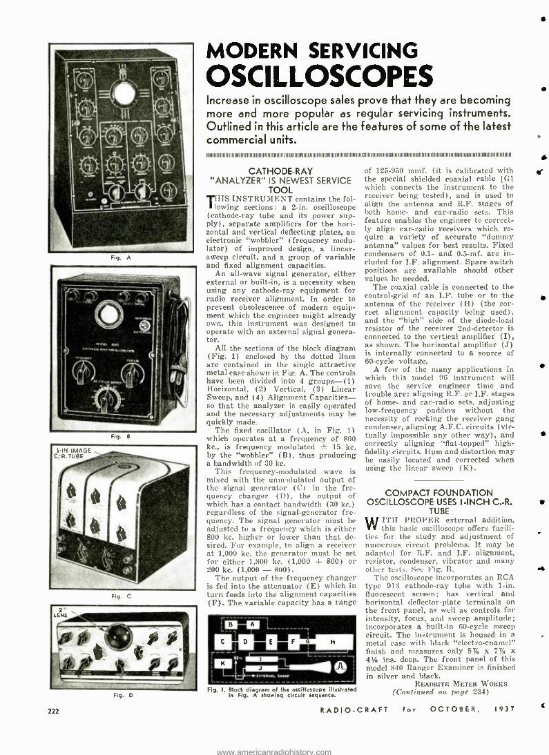
Fig. A
Fig. 8
Fig. C
Fig. D
222
MODERN SERVICING
OSCILLOSCOPES Increase in oscilloscope sales prove that they are becoming more and more popular as regular servicing instruments. Outlined in this article are the features of some of the latest commercial units. II IIII81181111I1III8 8 8 1 8111111181 1I1. 111111111111118111111I I8I IBII I I IIIIII1111I111111111111111111111111I IIIIIIII IIIIII811IIIIIIII IIIIBIIIII8111IIIIIIII IIIII1111111111111111111881I1.
CATHODE -RAY "ANALYZER" IS NEWEST SERVICE
TOOL
THIS INSTRUMENT contains the fol-
lowing sections: a 2 -in. oscilloscope (cathode -ray tube and its power sup- ply), separate amplifiers for the hori- zontal and vertical deflecting plates, an electronic "wobbler" (frequency modu- lator) of improved design, a linear - sweep circuit, and a group of variable and fixed alignment capacities.
An all -wave signal generator, either external or built -in, is a necessity when using any cathode -ray equipment for radio receiver alignment. In order to prevent obsolescence of modern equip- ment which the engineer might already own, this instrument was designed to operate with an external signal genera- tor.
All the sections of the block diagram (Fig. 1) enclosed by the dotted lines are contained in the single attractive metal case shown in Fig. A. The controls have been divided into 4 groups -(1) Horizontal, (2) Vertical, (3) Linear Sweep, and (4) Alignment Capacities - so that the analyzer is easily operated and the necessary adjustments may be quickly made.
The fixed oscillator (A, in Fig. 1) which operates at a frequency of 800 kc., is frequency modulated ± 15 kc. by the "wobbler" (B), thus producing a bandwidth of 30 kc.
This frequency -modulated wave is mixed with the unmodulated output of the signal generator (C) in the fre- quency changer (D), the output of which has a contact bandwidth (30 kc.) regardless of the signal- generator fre- quency. The signal generator must be adjusted to a frequency which is either 800 kc. higher or lower than that de- sired. For example, to align a receiver at 1,000 kc. the generator must be set for either 1,800 kc. (1,000 + 800) or 200 kc. (1,000 - 800) .
The output of the frequency changer is fed into the attenuator (E) which in turn feeds into the alignment capacities (F). The variable capacity has a range
Fig. I. Block diagram of the oscilloscope illustrated in Fig. A showing circuit sequence.
of 125 -950 mmf. (it is calibrated with the special shielded coaxial cable [GI which connects the instrument to the receiver being tested), and is used to align the antenna and R.F. stages of both home- and car -radio sets. This feature enables the engineer to correct- ly align car -radio receivers which re- quire a variety of accurate "dummy antenna" values for best results. Fixed condensers of 0.1- and 0.5 -mf. are in- cluded for I.F. alignment. Spare switch positions are available should other values be needed.
The coaxial cable is connected to the control -grid of an I.F. tube or to the antenna of the receiver (H) (the cor- rect alignment capacity being used), and the "high" side of the diode -load resistor of the receiver 2nd -detector is connected to the vertical amplifier (I), as shown. The horizontal amplifier (J) is internally connected to a source of 60 -cycle voltage.
A few of the many applications in which this model 96 instrument will save the service engineer time and trouble are: aligning R.F. or I.F. stages of home- and car -radio sets, adjusting low- frequency padders without the necessity of rocking the receiver gang condenser, aligning A.F.C. circuits (vir- tually impossible any other way), and correctly aligning "flat- topped" high - fidelity circuits. Hum and distortion may be easily located and corrected when using the linear sweep (K).
COMPACT FOUNDATION OSCILLOSCOPE USES I -INCH C.-R.
TUBE ITH PROPER external addition, this basic oscilloscope offers facili-
ties for the study and adjustment of numerous circuit problems. It may be adapted for R.F. and I.F. alignment, resistor, condenser, vibrator and many other tests. See Fig. B.
The oscilloscope incorporates an RCA type 913 cathode -ray tube with 1 -in. fluorescent screen; has vertical and horizontal deflector -plate terminals on the front panel, as well as controls for intensity, focus, and sweep amplitude; incorporates a built -in 60 -cycle sweep circuit. The instrument is housed in a metal case with black "electro- enamel" finish and measures only 57 /s x 7% x 4% ins. deep. The front panel of this model 840 Ranger Examiner is finished in silver and black.
READRITE METER WORKS (Continued on page 234)
W
RADIO -CRAFT for OCTOBER. 1937
e
441
t
www.americanradiohistory.com
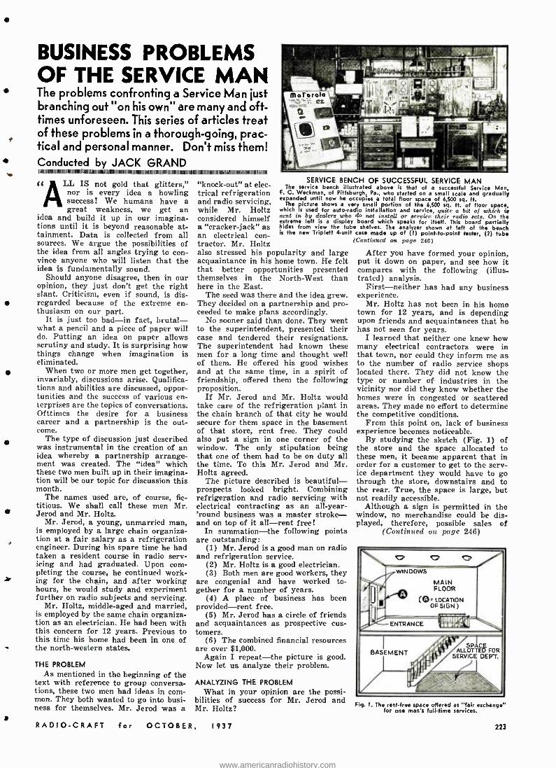
BUSINESS PROBLEMS OF THE SERVICE MAN The problems confronting a Service Man just branching out "on his own" are many and oft - times unforeseen. This series of articles treat of these problems in a thorough -going, prac- tical and personal manner. Don't miss them!
4 Conducted by JACK GRAND I I I I I I I I I I I I 1 1 1 1 1 1 1 11111111111 1 1 l l l l l 1111111111111111111111111111111111111111111I111111111111111111111111111111111111 1 111111111111111111111111111 ti 1111
ti LL IS not gold that glitters," nor is every idea a howling success! We humans have a great weakness, we get an
idea and build it up in our imagina- tions until it is beyond reasonable at- tainment. Data is collected from all sources. We argue the possibilities of the idea from all angles trying to con- vince anyone who will listen that the idea is fundamentally sound.
Should anyone disagree, then in our opinion, they just don't get the right slant. Criticism, even if sound, is dis- regarded because of the extreme en- thusiasm on our part.
It is just too bad -in fact, brutal - what a pencil and a piece of paper will do. Putting an idea on paper allows scrutiny and study. It is surprising how things change when imagination is eliminated.
When two or more men get together, invariably, discussions arise. Qualifica- tions and abilities are discussed, oppor- tunities and the success of various en- terprises are the topics of conversations. Ofttimes the desire for a business career and a partnership is the out- come.
The type of discussion just described was instrumental in the creation of an idea whereby a partnership arrange- ment was created. The "idea" which these two men built up in their imagina- tion will be our topic for discussion this month.
The names used are, of course, fic- titious. We shall call these men Mr. Jerod and Mr. Holtz.
Mr. Jerod, a young, unmarried man, is employed by a large chain organiza- tion at a fair salary as a refrigeration engineer. During his spare time he had taken a resident course in radio serv- icing and had graduated. Upon com- pleting the course, he continued work- ]. ing for the chain, and after working hours, he would study and experiment further on radio subjects and servicing.
Mr. Holtz, middle -aged and married, is employed by the same chain organiza- tion as an electrician. He had been with this concern for 12 years. Previous to this time his home had been in one of the north -western states.
THE PROBLEM As mentioned in the beginning of the
text with reference to group conversa- tions, these two men had ideas in com- mon. They both wanted to go into busi- ness for themselves. Mr. Jerod was a
"knock -out" at elec- trical refrigeration and radio servicing, while Mr. Holtz considered himself a "cracker- jack" as an electrical con- tractor. Mr. Holtz also stressed his popularity and large acquaintance in his home town. He felt that better opportunities presented themselves in the North -West than here in the East.
The seed was there and the idea grew. They decided on a partnership and pro- ceeded to make plans accordingly.
No sooner said than done. They went to the superintendent, presented their case and tendered their resignations. The superintendent had known these men for a long time and thought well of them. He offered his good wishes and at the same time, in a spirit of friendship, offered them the following proposition.
If Mr. Jerod and Mr. Holtz would take care of the refrigeration plant in the chain branch of that city he would secure for them space in the basement of that store, rent free. They could also put a sign in one corner of the window. The only stipulation being that one of them had to be on duty all the time. To this Mr. Jerod and Mr. Holtz agreed.
The picture described is beautiful - prospects looked bright. Combining refrigeration and radio servicing with electrical contracting as an all -year- 'round business was a master stroke - and on top of it all -rent free!
In summation -the following points are outstanding:
(1) Mr. Jerod is a good man on radio and refrigeration service.
(2) Mr. Holtz is a good electrician. (3) Both men are good workers, they
are congenial and have worked to- gether for a number of years.
(4) A place of business has been provided -rent free.
(5) Mr. Jerod has a circle of friends and acquaintances as prospective cus- tomers.
(6) The combined financial resources are over $1,000.
Again I repeat -the picture is good. Now let us analyze their problem.
SERVICE BENCH OF SUCCESSFUL SERVICE MAN The service bench illustrated above is that of a successful Service Man,
F. C. Weckman, of Pittsburgh, Pa., who started on a small scale and gradually expanded until now he occupies a total floor space of 6,500 sq. ft.
The Picture shows a very small portion of the 6,500 sq. ft. of floor space, which is used for auto -radio installation and service. quite a bit of which ie sent in by dealers who do not install or service their radio sets. On the extreme left is a display board which speaks for itself. This board partially hides from view the tube shelves. The analyzer shown at left of the bench is the new Triplett 4-unit case made up of (I) point -to -point tester. (2) tubs
ANALYZING THE PROBLEM What in your opinion are the possi
bilities of success for Mr. Jerod and Mr. Holtz?
RADIO -CRAFT for OCTOBER. 1937
(Continued on pago 246)
After you have formed your opinion, put it down on paper, and see how it compares with the following (illus- trated) analysis.
First- neither has had any business experience.
Mr. Holtz has not been in his home town for 12 years, and is depending upon friends and acquaintances that he has not seen for years.
I learned that neither one knew how many electrical contractors were in that town, nor could they inform me as to the number of radio service shops located there. They did not know the type or number of industries in the vicinity nor did they know whether the homes were in congested or scattered areas. They made no effort to determine the competitive conditions.
From this point on, lack of business experience becomes noticeable.
By studying the sketch (Fig. 1) of the store and the space allocated to these men, it became apparent that in order for a customer to get to the serv- ice department they would have to go through the store, downstairs and to the rear. True, the space is large, but not readily accessible.
Although a sign is permitted in the window, no merchandise could be dis- played, therefore, possible sales of
(Continued on page 246) © O WINDOWS
MAIN FLOOR
(Q= LOCATION OF SIGN)
ENTRANCE IÌItlIÚ9{' iii£dF
BASEMENT ALLSOTTED FOR SERVICE DENT.
Fig. I. The rent -free space offered as "fair exchang for one man's full -time services.
223
www.americanradiohistory.com
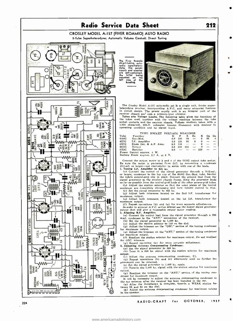
Radio Service Data Sheet 212 CROSLEY MODEL A -I57 (FIVER ROAMIO) AUTO RADIO
5 -Tube Superheterodyne; Automatic Volume Control; Direct Tuning
~
i;;L:Ì IWJ
Y
to (DS N ° a.
o ,
o 3
4.2 á ó2a
a Y > éa=ÑfR cn03
s3 , \^ v W _\ LL
ffffL
oc
^s a z
$ 1- -. QVylyttQy I
n
o
W o rD
LL
ly to w x
Ñ IL U
I O
ana Ó-
e.i
The Fiver Roamio direct -tuning, auto- radio superhetero- dyne. The power supply and speaker are self -contained, the latter being mounted on the left side of the
housing.
The Crosley Model A -157 auto -radio set is a single unit, 5 -tube super- heterodyne receiver, incorporating A.V.C. and many advanced features in circuit design. The power supply unit is an integral part of the receiver chassie ame uses a primary -type vibrator.
Tubes ana Voltage Limits. The following table gives the functions of the tubes used, together with the voltage readings between the tube socket contacts and the receiver chassis. Voltage readings taken with a.
1,000 ohms /volt, 500 -V. voltmeter (except filaments) with receiver in operating condition and no signal input.
TUBE SOCKET VOLTAGE READINGS Tube Function H P S Su K Ca G.. 6A8G Osc: Mod. 6.0 220 90 - 0 90 4)
6Z7G I.F. Amplifier 6.0 220 90 0 0 - - 6Q7G Diode Det. & A.F. Amp. 6.0 110 - - 0
Output 6.0 200 220 - 0 - - 6R5G Rectifier 6.0 - - - 220 - - Power Output approx. 4 W. Battery Drain approx. 5.7 A. at 6 V.
Connect the output meter to 3 and 4 of the 6K6G output tube socket. Be sure the meter is protected from D.C. by connecting a condenser (0.1 -mf. or larger -not electrolytic) in series with one of the leads. 1. Tuning I.F. Amplifier to 455 kc.
(a) Connect the output of the signal generator through n 0.02 -mf.. or larger. condenser to the top cap of the 6A8G Osc: Mod. tube, leaving the tube's control -grid clip in place. Connect the ground lead from the signal generator to the receiver chassis frame. Keep the generator leads as far as possible from the control -grid lends of the other screen -grid tubes.
(b) Adjust the station selector so that the rotor plates of the tuning condenser are completely disengaged and turn volume control to max.
(c) Set the signal generator to 455 kc. (d) Adjust both trimmers located on the 2nd I.F. transformer for
maximum output. (e) Adjust both trimmers located on the 1st I.F. transformer for
maximum output. (f) Repeat operations (d) and (e) for more accurate adjustments. In order to prevent A.V.C. action always use the lowest signal generator
output that will give a reasonable output meter reading. 2. Aligning R.F. Amplifier.
(a) Connect the output lead from the signal generator through a 250 mmf. condenser to the "ANT." connection of the receiver.
(b) Set the signal generator to 1,400 kc. (c) Adjust the station selector to 140 on the dial. (d) Adjust the trimmer on the "OSC." section of the tuning condenser
for maximum output. (e) Adjust the trimmer on the "ANT." section of the tuning condenser
for maximum output. (f) Readjust the station selector for maximum output. Do not readjust
the OSC. trimmer. (g) Repeat operation (e) for more accurate adjustment.
3. Adjusting Antenna Compensating Condenser. (a) Set the signal generator to 600 kc. (b) Tune in a 600 kc. signal with the station selector for maximum
output. (e) Adjust the antenna compensating condenser, Cl. (d) Repeat operations (b) and (c) alternately until no further im-
provement can be obtained. (e) Set the signal generator to 1,400 kc. again. (f) Tune -in the 1,400 ke. signal with the station selector for maximum
output. (g) Readjust the trimmer on the "ANT." section of the tuning con-
denser for maximum output. It will be necessary to adjust the antenna compensating condenser to
the car antenna after the receiver has been installed in the car. (a) After the installation is complete, tune -in a WEAK station be-
tween 55 and 65 on the dial. (b) Adjust the antenna compensating condenser for maximum volume
in the speaker.
224 RADIO -CRAFT for OCTOBER, 1937
i
www.americanradiohistory.com
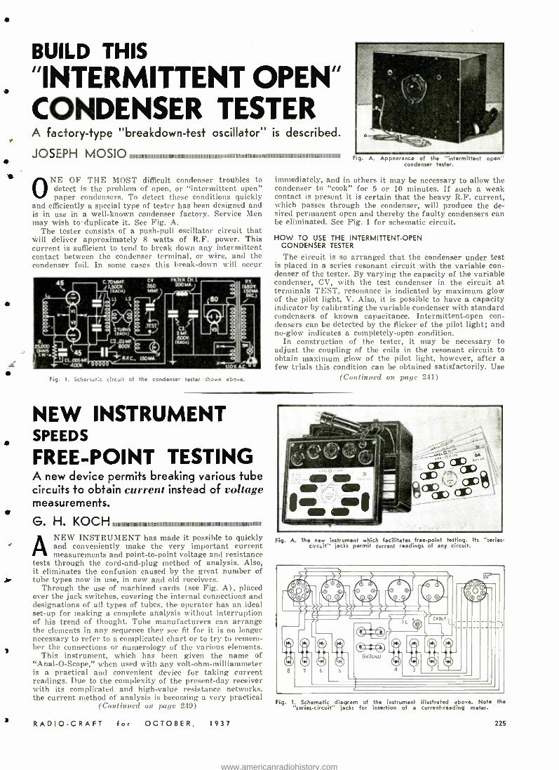
BUILD THIS
"INTERMITTENT OPEN" CONDENSER TESTER A factory -type "breakdown -test oscillator" is described.
JOSEPH MOSTO
i
O NE OF THE MOST difficult condenser troubles to detect is the problem of open, or "intermittent open" paper condensers. To detect these conditions quickly
and efficiently a special type of tester has been designed and is in use in a well -known condenser factory. Service Men may wish toduplicate it. See Fig. A.
The tester consists of a push -pull oscillator circuit that will deliver approximately 8 watts of R.F. power. This current is sufficient to tend to break down any intermittent contact between the condenser terminal, or wire, and the condenser foil. In some cases this break -down will occur
45
L
C.70MMF 1500V. (snow)
u L2 / \
CV
350 MMF. l
VIITLR CH .1
200 MA.
45 CI.00SMF. - 400V
2TURN5
C2,D1.MF / 800V
I R.FC.. 150MA..
V.T.
(650v 15061A SEC.) i o o °o
C3.
á00v. (ucv)
x 110V A.C.
Fig. I. 5d nef;. circuit of the condenser tester s`,ow.., ab_e.
Fig A. Appearance of the "intermittent open' condenser tester.
immediately, and in others it may be necessary to allow the condenser to "cook" for 5 or 10 minutes. If such a weak contact is present it is certain that the heavy R.F. current, which passes through the condenser, will produce the de- sired permanent open and thereby the faulty condensers can be eliminated. See Fig. 1 for schematic circuit.
HOW TO USE THE INTERMITTENT -OPEN CONDENSER TESTER
The circuit is so arranged that the condenser under test is placed in a series resonant circuit with the variable con- denser of the tester. By varying the capacity of the variable condenser, CV, with the test condenser in the circuit at terminals TEST, resonance is indicated by maximum glow of the pilot light, V. Also, it is possible to have a capacity indicator by calibrating the variable condenser with standard condensers of known capacitance. Intermittent -open con- densers can be detected by the flicker of the pilot light; and no -glow indicates a completely -open condition.
In construction of the tester, it may be necessary to adjust the coupling of the coils in the resonant circuit to obtain maximum glow of the pilot light, however, after a few trials this condition can be obtained satisfactorily. Use
(Continued on page 241)
NEW INSTRUMENT SPEEDS
FREE -POINT TESTING A new device permits breaking various tube circuits to obtain current instead of voltage measurements.
A
H. KOCH IlfRlllfflfffllftlffllfllRRRiRfRffllflffllllilfllRRRRRRRi fRRRRRRRRRffiRRii
NEW INSTRUMENT has made it possible to quickly and conveniently make the very important current measurements and point -to -point voltage and resistance
tests through the cord- and -plug method of analysis. Also, it eliminates the confusion caused by the great number of tube types now in use, in new and old receivers.
Through the use of machined cards (see Fig. A), placed over the jack switches, covering the internal connections and designations of all types of tubes, the operator has an ideal set -up for making a complete analysis without interruption of his trend of thought. Tube manufacturers can arrange the elements in any sequence they see fit for it is no longer necessary to refer to a complicated chart or to try to remem- ber the connections or numerology of the various elements.
This instrument, which has been given the name of "Anal -O- Scope," when used with any volt -ohm- milliammeter is a practical and convenient device for taking current readings. Due to the complexity of the present -day receiver with its complicated and high -value resistance networks. the current method of analysis is becoming a very practical
(Continued on page 249)
RADIO -CRAFT for OCTOBER, 1937
Fig A. The new instrument which facilitates free -point testing. Its circuit" jacks permit current readings of any circuit.
"series-
Fig. I. Schematic diagram of the instrument illustrated above. Note the "series- circuit" jacks for insertion of a current -reading meter.
225
www.americanradiohistory.com
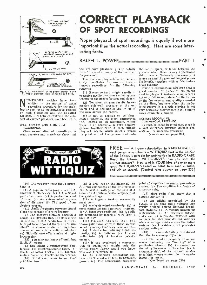
.....,.. r
PROPER ANGLE OF NEEDLE WHEN PLAYING
BACK ACETATES
O E, 30 TO 32 DEG.
WHEN LESS THAN 30 DEG.
G TRAILING -SHOED PLAYBACK NEEDLE
Fig. I. A, Adjustments of the phono pickup; B and C, Proper playback angle of needle and head.
NUMEROUS articles have been written in the matter of exact recording procedure for the mak-
ing or cutting of instantaneous records on both aluminum and the so- called acetates. But articles covering the sub- ject of correct playback have been rare.
WAX, ACETATE AND ALUMINUM RECORDINGS Close examination of recordings on
wax, acetates and aluminum show that
CORRECT PLAYBACK OF SPOT RECORDINGS Proper playback of spot recordings is equally if not more important than the actual recording. Here are some inter- esting facts.
RALPH L. POW ERIIIIIIIIIIIIIIIIIIIIIIIIIIIIIIIIIIIIIIIIIIIIIIIIIIIIIIIIIIIIIIIIIIIIIIIIIIIIIIIIIIIIIIIIIIIIIIIIIIIIIIIIIIPA RT I
the ordinary playback pickup totally fails to reproduce many of the recorded frequencies!
The average playback set -up is en- tirely unsuitable for use on instan- taneous recordings, for the following reasons:
(1) Excessive head weight results in excessive needle pressure (which causes tearing of the groove bottom and sides) ;
(2) Too -short an arm results in ex- cessive side -wall pressure at the ex- treme end of the are in the swing of the arm across the record.
While not so serieus on cellulose - coated material, its most aggravated form shows up on aluminum, where there is of necessity, a very shallow groove together with a soft, pliable playback needle which quickly wears its point out of the groove and onto
vorit RADIO
WITTIQUIZ (10) Did you ever know that ampere -
hour is- (a) A popular radio program. (b) A
quantity of electricity. (c) A fractional part of an hour. (d) A particular kind of time. (e) An astronomical expres- sion of distance. (f) The speed of an electric current.
(.11) Radio- frequency currents travel along the surface of a wire because -
(a) The shortest distance between 2 points is a straight line. (b) 2nR is the circumference of a conductor. (c) Cen- trifugal force drives it there. (d) "Skin - effect" is characteristic of high -fre- quency currents in a solid conductor. (e) Skip- distance effects arise at high - frequencies.
(12) You may not know offhand, but E. M. F. means -
(a) Equipment Manufacturers Fra- ternity. (b) Electromagnetic force. (c) Electrical motor friction. (d) Electro- motive force. (e) Electrical microfarad.
(13) Did it ever occur to you that grid bias is- 226
the record space, or lands between the grooves when there is any appreciable side pressure. Naturally, the remedy is to use an arm the greatest longest possi- ble length, together with a frictionless pivot bearing.
Further examination discloses that a great number of pieces of equipment used to playback instantaneous records not only fail to reproduce for the listen- er the frequencies and quality recorded on the discs, but very often the modu- lated groove in a single playing is not only seriously deteriorated but in many cases completely ruined.
ACETATE RECORDS VS. COMMERCIAL PRESSINGS
It must be borne in mind that there is a vast difference between acetate rec- ords and commercial pressings.
(Continued on page 244)
FREE -A I -year subscription to RADIO -CRAFT to each person who submits a WITTIQUIZ that in the opinion of the Editors is suitable for publication in RADIO -CRAFT. Read the following WITTIQUIZZES; can you spot the correct answers? Now send in YOUR idea of one or more good WITTIQUIZZES based on some term used in radio, and win an award. (Contest rules appear on page 235.)
'IIIIIII IIIIIIIIIIIIII IIIIIIIIII IIIIII IIIIIIIIIIIIHIIIIII IIIIII IIIIIIII I I IIIIII IIII IIIIII I IIIIIIIII IIIIIIII IIIIIIIII I IIIIIIIIIIIIIIIIIIIIIIIIIIIW li
(a) A grid, cut on the diagonal. (b) A direct component of the grid voltage. (c) A neutral voltage on the grid of a tube. (d) An intermediate component of the grid voltage.
(14) A haywire hookup necessarily must be-
(a) A circuit wired carelessly. (b) A cross -connected radio network program. (c) A farm -type radio set. (d) A radio set connected by means of wire from a bale of hay.
(15) Volume control. Are you thoroughly familiar with these words? Would you say that they referred to-
(a) A device for reducing signal in- tensity. (b) A dietician. (e) A weak radio tube. (d) A low -loss potenti- ometer.
(16) If you overheard a conversa- tion in which you caught only the words power factor would you know this was a reference to-
(a) An electricity generating sta- tion. (b) The ratio of true to apparent power. (c) The nomograph crossover
point of amplification versus percentage curves. (d) The amplification factor of a power tube.
(17) Most radio fans know that a voltage divider is-
(a) An official appointed by the F.C.C. to see that radio voltages are evenly divided among licensed broad- cast stations. (b) A voltage- measuring instrument. (c) An electrical mathe- matician. (d) A resistor provided with contacts for obtaining desired voltages when a voltage exists across the entire resistor. (e) A resistor which generates various voltages.
(18) It is now definitely established that the Luxemburg Effect is:
(a) The peculiar property of micro- waves hastening the "souring" of a particular cheese. (b) Cross- modula- tion of radio waves in the ether. (e) A frequency drift of the transmitter due to a high cheese content in the casein insulating parts.
(Continued on page 235)
RADIO -CRAFT for OCTOBER, 1937
r
Y
l
l
www.americanradiohistory.com
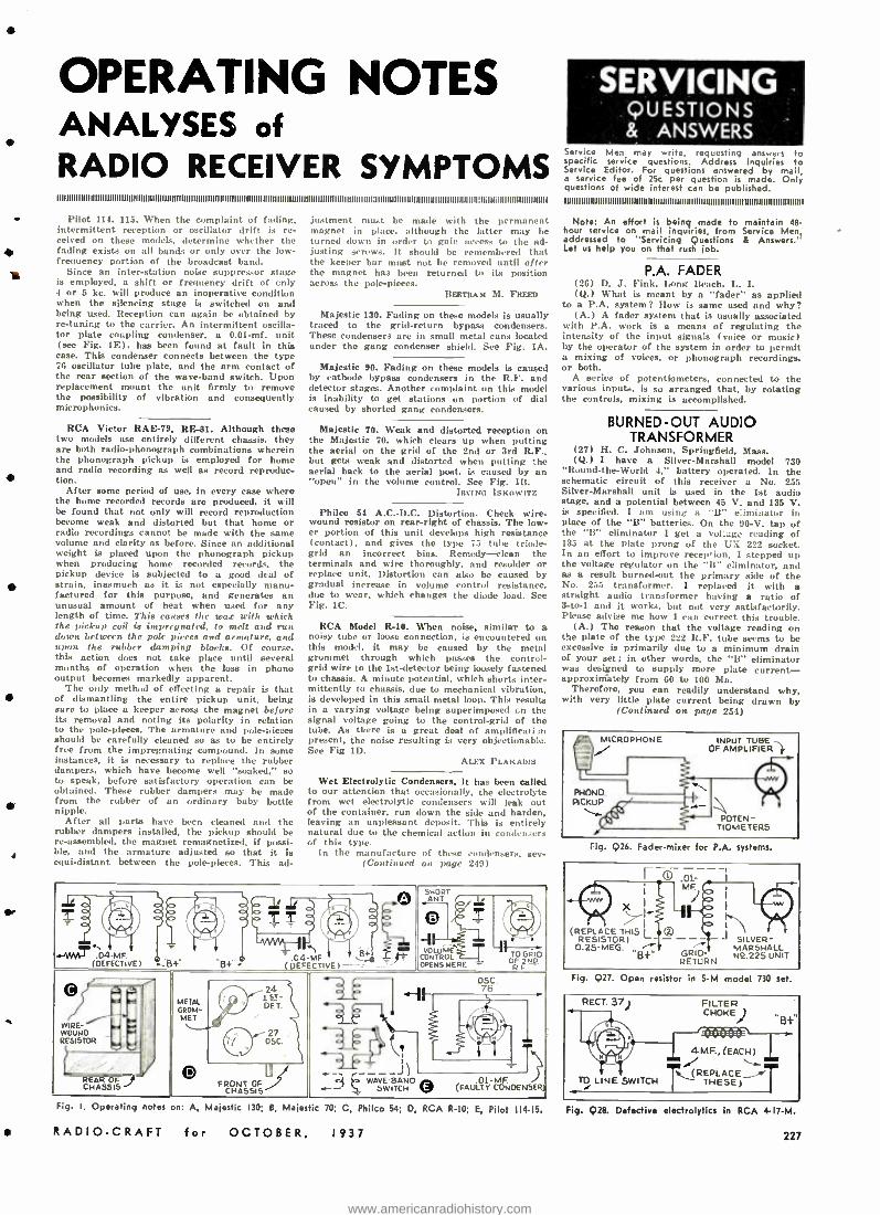
OPERATING NOTES ANALYSES of RADIO RECEIVER SYMPTOMS 1111111111111111IIIIIIIIIIIIIIIIIIIIIIIIIII IIIIIIIIIIIIIIIIIIII11111111111111111111111111111111111111111111111111111IIIIIIIIIII I1111:1IIIIIIIIIIIIIIIIIIIIIIIII111111111IIIIIIIIIIIiIIli11I1lI1II1111IIIIlI11
Pilot 114, 115. When the complaint of fading, intermittent reception or oscillator drift is re- ceived on these models, determine whether the fading exists on all bands or only over the low - frequency portion of the broadcast band.
Since an inter -station noise suppressor stage is employed, a shift or frequency drift of cnly 4 or 5 kc. will produce an inoperative condition when the silencing stage is switched on and being used. Reception can again be obtained by re- tuning to the carrier. An intermittent oscilla- tor plate coupling condenser, a 0.01 -mf. unit (see Fig. 1E), has been found at fault in this
case. This condenser connects between the type 76 oscillator tube plate, and the arm contact of the rear section of the wave -band switch. Upon replacement mount the unit firmly to remove the possibility of vibration and consequently microphonics.
RCA Victor RAE -79, RE-81. Although these two models use entirely different chassis. they are both radio -phonograph combinations wherein the phonograph pickup is employed for home and radio recording as well as record reproduc- tion.
After some period of use, in every case where the home recorded records are produced, it will be found that not only will record reproduction become weak and distorted but that home or radio recordings cannot be made with the same volume and clarity as before. Since an additional weight is placed upon the phonograph pickup when producing home recorded records, the pickup device is subjected to a good deal of strain, inasmuch as it is not especially manu- factured for this purpose. and generates an unusual amount of heat when used for any length of time. This causes the wax with which the pickup coil is impregnated, to melt and run down between the pole pieces and armature. and upon the rubber damping blocks. Of course. this action does not take place until several months of operation when the loss in phono output becomes markedly apparent.
The only method of effecting a repair is that of dismantling the entire pickup unit, being sure to place a keeper across the magnet before its removal and noting its polarity in relation to the pole- pieces. The armature and pole- pieces should be carefully cleaned so as to be entirely free from the impregnating compound. In some instances, it is necessary to replace the rubber dampers, which have become well "soaked," so to speak, before satisfactory operation can be obtained. These rubber dampers may be made from the rubber of an ordinary baby bottle nipple.
After all parts have been cleaned and the rubber dampers installed, the pickup should be re- assembled, the magnet remagnetized, if possi- ble, and the armature adjusted so that it is equi- distant between the pole-pieces. This ad-
justment must be made with the permanent magnet in place, although the latter may be turned down in order to gain access to the ad- justing screws. It should be remembered that the keeper bar must not be removed until after the magnet has been returned to its position across the pole- pieces.
BERTRAM M. FREED
Majestic 130. Fading on these models is usually traced to the grid- return bypass condenser,. These condensers are in small metal cans located under the gang condenser shield. See Fig. 1A.
Majestic 90. Fading on these models is caused by cathode bypass condensers in the R.F. and detector stages. Another complaint on this model is inability to get stations on portion of dial caused by shorted gang condensers.
Majestic 70. Weak and distorted reception on the Majestic 70, which clears up when putting the aerial on the grid of the 2nd or 3rd R.F., but gets weak and distorted when putting the aerial back to the aerial post, is caused by an "open" in the volume control. See Fig. 113.
blot/tic Isxnweri
Philco 54 A.C.-D.C. Distortion. Check wire - wound resistor on rear -right of chassis. The low- er portion of this unit develops high resistance (contact), and gives the type 75 tube triode - grid an incorrect bias. Remedy -clean the terminals and wire thoroughly, and resolder or replace unit. Distortion can aLso be caused by gradual increase in volume control resistance, due to wear. which changes the diode load. See Fig. 1C.
RCA Model R-10. When noise, similar to a noisy tube or loose connection, is encountered on this model, it may be caused by the metal grommet through which passes the control - grid wire to the 1st- detector being loosely fastened to chassis. A minute potential, which shorts inter- mittently to chassis, due to mechanical vibration. is developed in this small metal loop. This results in a varying voltage being superimposed on the signal voltage going to the control -grid of the tube. As there is a great deal of ampliflcati.1 present, the noise resulting is very objectionable. See Fig 1D.
ALEX PLAKAPIs
Wet Electrolytic Condensers. It has been called to our attention that occasionally, the electrolyte from wet electrolytic condensers will leak out of the container, run down the side and harden. leaving an unpleasant deposit. This is entirely natural due to the chemical action in condensers of this type.
In the manufacture of these condensers. sev- (Continued on page 249)
SHORT ANT.
w ` TT TT ` O
-W .04 MF. (DEFECTIVE) .- 6+ -B +'. 04
(DEF MF 64 CTIVEI -c_.- CONTROL TO GRID
OPENS HERE ? ?? OF 2NO. RF
WIRE - WOUND RESISTOR
1.- I +
METAL
MET
24 1sT-
OS C. J 76 _ 1
O05C. 7
iTL4J) O FRONT OF CHASSIS
el WAVEBAND .01-MF ..--- SWITCH (FAULTY CONDENSER) REAR OF J CHASSIS
Fig. I. Operating notes on: A, Majestic 130; B, Maje tic 70; C, Philco 54; D, RCA R -I0; E, Pilot 11415,
RADIO -CRAFT for OCTOBER, 1937
SERVICING QUESTIONS & ANSWERS
Service Men may write, requesting answers to specific service questions. Address inquiries to Service Editor. For questions answered by mail, a service fee of 25c per question is made. Only questions of wide interest can be published. IIII1111IIIIII IIIIII1111IIIIIIIIIII IIIIIIII II IIIIIIII II I I IIIIIIII IIIII IIIIIB I IIIII I III I I Illlllllll I
Note: An effort is being ade to maintain 48- hour service on mail inquiries. from Service Men, addressed to "Servicing Questions & Answers." Let us help you on that rush job.
P.A. FADER (26) D..1. Fink, Long Beach, L. I. (Q.) What is meant by a "fader" as applied
to a P.A. system? How is same used and why? (A.) A fader system that is usually associated
with P.A. work is a means of regulating the intensity of the input signals (voice or music) by the operator of the system in order to permit a mixing of voices, or phonograph recordings, or both.
A series of potentiometers, connected to the various inputs, is so arranged that, by rotating the controls, mixing is accomplished.
BURNED -OUT AUDIO TRANSFORMER
(27) H. C. Johnson, Springfield, Mass. (Q.) I have a Silver -Marshall model 730
"Round- the -World 4," battery operated. In the schematic circuit of this receiver a No. 255 Silver -Marshall unit is used in the 1st audio stage. and a potential between 45 V. and 135 V. L specified. I am using a "B" a :imil:atur in place of the "B" batteries. On the 90 -V. tap of the "B" eliminator I get a vol::,. e reading of 135 at the plate Prong of the UX 222 socket. In an effort to improve reception, I stepped up the voltage regulator on the "B" eliminator, and as a result burned -out the primary side of the No. 255 transformer. I replaced it with a straight audio transformer having a ratio of 3 -to -1 and it works, but not very satisfactorily. Please advise me how I can correct this trouble.
(A.) The reason that the voltage reading on the plate of the type 222 R.F. tube seems to be excessive is primarily due to a minimum drain of your set; in other words. the 'B" eliminator was designed to supply more plate current - approximátely from 60 to 100 Ma.
Therefore, you can readily understand why, with very little plate current being drawn by
(Continued on page 254)
!:o. jlPICKUP
i'
MICROPHONE INPUT TUBE OF AMPLIFIER
POTEN- TIOMETERS
Fig. 926. Fader -mixer for P.A. systems.
X I
(REPLACE THIS L I
RESISTOR) 0.25-MEG. B
T- MF.
(g)- SILVER -
GRID MARSHALL
RETURN N4.225 UNIT
Fig. Q27. Open resistor in S -M model 730 set.
Fig. 928. Defective electrolytic' in RCA 417 -M.
227
www.americanradiohistory.com
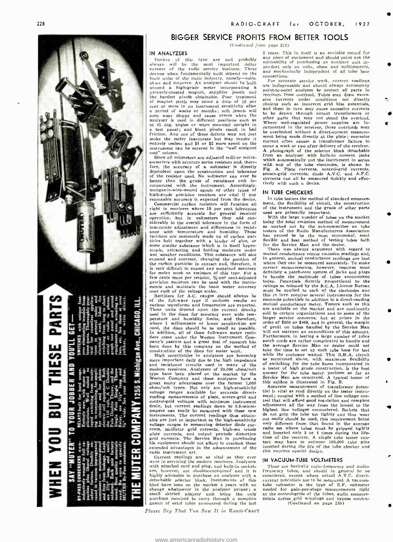
228 RADIO -CRAFT for OCTOBER, 1937
BIGGER SERVICE PROFITS FROM BETTER TOOLS (Coutin ucd franc pagc 210)
2 years. This in itself is an enviable record for any piece of equipment and should point out the advisability of purchasing an analyzer unit de- pendent only on volts, ohms and milliamperes, and mechanically independent of all tube base connections.
For accurate service work, current readings are indispensable and should always accompany point- to-point analyses to protect all parts in receivers from overload. Tubes may draw exces- sive currents under conditions not directly obvious such as incorrect grid bias potentials, and these in turn may cause excessive currents to be drawn through output transformers or other parts that may not stand the overload. Where well -regulated power supplies are in- corporated in the receiver, these overloads may be overlooked without a direct -current measure- ment being made directly at the plate; excessive current often causes a transformer failure to occur a week or two after delivery of the receiver. A photograph of the selector block detachable from an analyzer with built -in current jacks which automatically put the instrument in series with any of the tube electrodes, is shown in Fig. A. Plate currents, control -grid currents, screen -grid currents, diode A.V.C. and A.F.C. currents can all be measured quickly and effec- tively with such a device.
IN ANALYZERS )CV 112(. of this type are and probably
always will be the most important dollar earners of the radio service business. These devices when fundamentally built depend on the basic units of the radio industry, namely--- votis. ohms and amperes. An analyzer should be built around a high -grade meter incorporating a properly- treated magnet, sapphire jewels and the hardest pivots obtainable. Poor treatment of magnet steels may cause a drop of 10 per cent or more in an instrument sensitivity after a period of weeks or months; soft jewels will soon wear sloppy and cause errors when the analyzer is used in different positions such as at 45 deg. angles or when mounted upright in a test panel; and blunt pivots result in bad friction. Any one of these defects may not just make the meter inaccurate but may render it entirely useless and $1 or $2 more spent on the instrument can be entered in the "well assigned cost" column.
Since all voltmeters are adjusted milli -or micro- ammeters with accurate series resistors and, there- fore, the accuracy of a voltmeter is directly dependent upon the construction and tolerance of the resister used. No voltmeter can ever be better than the grade of resistance unit in- corporated with the instrument. Accordingly, manganin- wire -wound spools or other types of high -grade precision resistors are vital if any reasonable accuracy is expected from the device.
Commercial carbon resistors will function all right in receivers where 10 per cent tolerances are sufficiently accurate for general receiver operation, but in voltmeters they add con- siderably to the overall tolerance in the form of inaccurate adjustment and differences in resist- ance with temperature and humidity. These resistors are commonly made up of carbon par- ticles held together with a binder of glue, or some similar substance which is in itself hygro- scopic, attracting and holding moisture under suet weather conditions. This substance will also expand and contract. changing the position of the carbon particles in contact and, therefore, it is very difficult to expect any sustained accuracy for meter work on resistors of this type. For a few cents more per resistor, 'Ai -per cent -adjusted precision resistors can be used with the instru- ments and maintain the basic meter accuracy over each of the voltage scales.
Rectifiers for A.C. ranges should always be of the full -wave type if uniform results on various waveforms and frequencies are expected. These units depend upon the current density used in the discs for accuracy over wide tem- perature and humidity limits, and therefore, where 1 milliampere or lower sensitivities are used, the discs should be as small as possible. In addition, all of these full -wave meter recti- fiers come under the Weston Instrument Com- pany patents and a great deal of research has been done by this company on the method of construction of the discs for meter work.
High sensitivities in analyzers are becoming more important daily due to the high impedance and resistance circuits used in many of the modern receivers. Analyzers of 20,000 ohms /volt type have been placed on the market by the Weston Company and these analyzers have a great many advantages over the former 1,000 ohms /volt types. Not only are high -sensitivity voltage ranges available for accurate direct - reading measurements of plate, screen -grid and control -grid voltages with minimum instrument drain, but current readings down to 0.5- micro- ampere can easily be measured with these new instruments. The current readings thus obtain- able are just as important as the high -sensitivity voltage ranges in measuring detector diode cur- rents, oscillator grid currents, high -mu triode plate currents, and output pentode distortion grid currents. The Service Man in purchasing his equipment should not afford to overlook these extended advantages in the advancement of the radio instrument art.
Current readings are as vital as they ever were in servicing the modern receivers. Analyzers with attached cord and plug, and built -in sockets are, however, not obsolescence -proof and it is highly advisable to purchase an analyzer with a detachable selector block. Instruments of this kind have been on the market 4 years with no change whatsoever in the analyzer proper; a .small skirted adapter unit being the only purchase required to carry through a complete gamut of octal tubes announced during the last
Please Say That You Saw It in RADIO -CRAFT
IN TUBE CHECKERS In tubo testers the method of standard measure-
ment. the flexibility of circuit, the construction of the instrument and the grade of other parts used are primarily important.
With the large number of tubes on the market today the total emission method of measurement as worked out by the sub- committee on tube testers of the Radio Manufacturers Association has proved to be the most economical, most flexible and best method of testing tubes both for the Service Man and the dealer.
There was always argument with regard to mutual conductance versus emission readings and, in general, mutual conductance readings are best where they can be measured accurately. To make correct measurements, however, requires most definitely a patch -cord system of jacks and plugs to handle the multitude of tubes encountered today. Potentials directly proportional to the ratings as released by the R.C.A. License Bureau must be applied to each of the electrodes and this in turn requires several instruments for the electrode potentials in addition to a direct -reading mutual conductance meter. Testers such as this are available on the market and are continually sold to certain organizations and to some of the larger service concerns, but at prices in the order of $300 or $400, and in general, the margin of profit on tubes handled by the Service Man will not warrant an expenditure of this amount. Furthermore, in testing a large number of tubes patch cords are rather complicated to handle and the average Service Man or dealer could not take the time to set up each tube base for test while the customer waited. This R.M.A. circuit as mentioned above, with maximum flexibility of switching for the tube bases incorporated in a tester of high grade construction, is the best answer for the tube tester problem as far as Service Men are concerned. A typical tester of this calibre is illustrated in Fig. B.
Accurate measurement of transformer poten- tial is vital as read directly on the teeter instru- ment; coupled with a method of line voltage con- trol that will afford good regulation and complete adjustment all the way from the lowest to the highest line voltages encountered. Sockets that do not grip the tube too tightly and thus wear out easily should be used, this requirement being very different from that found in the average radio set where tubes must be gripped tightly and inserted only 3 or 4 times during the life- time of the receiver. A single tube tester con- tact may have to outwear 100,000 tube pins inserted during the life of the tube checker and this requires special design.
IN VACUUM -TUBE VOLTMETERS These are baiea II y rain iu- frequency and audio-
frequency tubes, and should in general be so considered, except where actual A.V.C. direct - current potentials are to be measured. A vacuum - tube voltmeter is the type of R.F. voltmeter needed for gain -per -stage measurements right at the control -grids of the tubes, audio measure- ments across grid windings and bypass conden-
(Continued on pago 230)
www.americanradiohistory.com
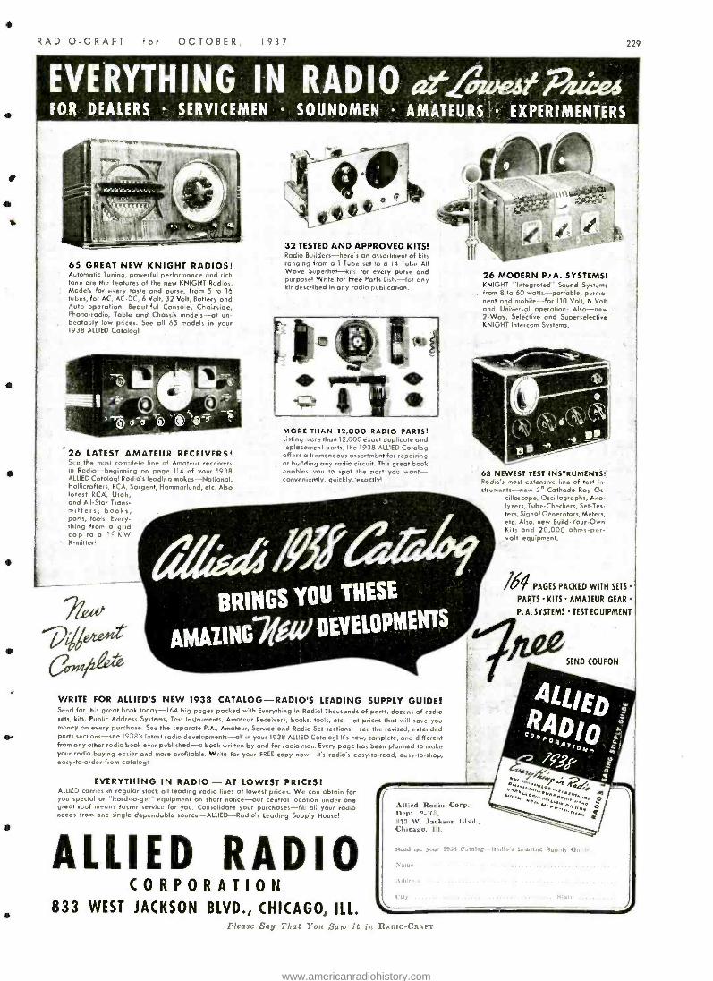
RADIO -CRAFT fo- OCTOBER, 1937 229
EVERYTHING IN RADIO atliweseakos FOR DEALERS SERVICEMEN SOUNDMEN AMATEURS EXPERIMENTERS
65 GREAT NEW KNIGHT RADIOS! Automatic Tuning, powerful performance und rich tone are the features of the new KNIGHT Radios. Models for every taste and purse, from 5 to 16 tubes, for AC, AC -DC, 6 Volt, 32 Volt, Battery and Auto operation. Beautiful Console, Chairside, Phono -radio, Table and Chassis models -at un- beatably low prices. See all 65 models in your 1938 ALLIED Cotalog!
26 LATEST AMATEUR RECEIVERS! See the most complete line of Amateur receivers in Radio- beginning on page 114 of your 1938 ALLIED Catalog! Radio's leading makes-National, Hollicrafters, RCA, Sargent, Hammerlend, etc. Also latest RCA, Utah, and All -Star Trans- mitters; books, parts, tools. Every- thing from a grid cap to a 1( KW X- milled
e 07710-"
v
:
Q. ritt, .40*
32 TESTED AND APPROVED KITS! Rodio Builders- here's un assortment of kits ranging from a 1 Tube set to a 14 Tube All Wave Superhel -kits for every purse and purpose! Write for Free Pans Lists -for any kit described in any radio publication.
filpfe
MORE THAN 12,000 RADIO PARTS! Listing more than 12,000 exact duplicate and replacement parts, the 1938 ALLIED Catalog offers a tremendous assortment for repairing or building any radio circuit. This great book enables you to spot the port you want - conveniently, quickly,eaoctly!
26 MODERN PIA, SYSTEMS! KNIGHT "Integrated" Sound Systems
. from 8 to 60 watt s -portable, permo- nent and mobile -for 110 Volt, 6 Volt and Universal operation: Also -new 2 -Way, Selective and Superselective KNIGHT Intercom Systems.
68 NEWEST TEST INSTRUMENTS! Radio's most extensive line of test in- struments-new 2" Cathode Ray Os-
cilloscope, Oscillogrophs, Ana- lyzers, Tube -Checkers, Set -Tes- ters, Signal Generators, Meters, etc. Also, new Build -Your -Own Kill and 20,000 ohms -per- volt equipment.
16T PAGES PACKED WITH SETS
PARTS KITS AMATEUR GEAR
P.A. SYSTEMS TEST EQUIPMENT
SEND COUPON
WRITE FOR ALLIED'S NEW 1938 CATALOG - RADIO'S LEADING SUPPLY GUIDE! Send for this great book today -164 big pages packed with Everything in Radio! Thousands of parts, dozens of radio sets, kits, Public Address Systems, Test Instruments, Amateur Receivers, books, tools, etc. -at prices that will save you money on every purchase. See the separate P.A, Amateur, Service and Radio Set sections -see the revised, extended ports sections -see 1938's latest radio developments -all in your 1938 ALLIED Catalog! It's new, complete, and different from any other radio book ever published -a book written by and for radio men. Every page has been planned to make your radio buying easier and more profitable. Write for your FREE copy now -it's radio's easy -to-read, easy -to -shop, easy -to- order -from catalog!
EVERYTHING IN RADIO - AT LOWEST PRICES! ALLIED carries in regular stock all leading radio lines at lowest prices. We can obtain for you special or "hard -to -get' equipment on short notice -our central location under one great roof means faster service for you. Consolidate your purchases -fill all your radio needs from one single dependable source -ALLIED -Radió s Leading Supply House!
ALLIED RADIO CORPORATION
833 WEST JACKSON BLVD., CHICAGO, ILL.
Allied Radio Corp., Dept. 2 -K8, 833 W. Jackson Blvd., Chicago, Ill.
Need MC your
.,,L!r,.
, i'aLdny -Had S 1.oa,ImK SUN.], i
N:.,
Please Say That You Saw It in RADIO-t lRAFT
www.americanradiohistory.com
230
CINAUDAGRAPH
)11,---\
CIINAUDAGRAH Magic Magnet Speakers -extensively utilized by all leading radio re-
ceiver and P. A. equipment manufacturers -are available in a complete range of sises from 51/2
to IB inches. to meet your every radio require. ment.
If you demand utmost dependability and fidel-
ity of reproduction from your equipment -in- sist on Cinaudagraph P. M. speakers. Carried in stock by all progressive distributors. Free de-
scriptive literature on request.
CINAUDAGRAPH CORPORATION Speaker Division Stamford, Conn.
6oöv. ELECTRC)LYTICS
Your choice of either metal -can or card- board -case general- utility electrolytic'. Compact. Fit anywhere. Inexpensive.
**600 v. D.C. working. Provide extra safety margin. Use them to meet high surge voltages.
Metal -can type inverted -screw mounted. Cardboard type has Adjustimount univer- sal metal flanges.
New CATALOG. 15th Anniversary Edition. new
items. Ask your jobber -or write us di rect. r-
CORPORATION 70 Wr'v m,pm SI. Brooklyn. N. Y.
RADIO -CRAFT for OCTOBER, 1937
BIGGER SERVICE PROFITS FROM BETTER TOOLS I trill tic m d frort Pap,' 22B)
sers, R.F. potentials in superheterodyne oscillator circuits, in trap circuit adjustments and in response -curve measurements.
Copper -oxide rectifier instruments cannot be used to advantage on R.F. resonant circuits be- cause of frequency limitations and due to the fact that any loading of these circuits tends to pull them out of resonance. The direct inser- tion of a vacuum tube is about the only other method of measuring the potentials across these circuits. In this regard, a well -designed volt- meter should have a minimum input capacity, connections being made directly to the tube with no voltage divider or selector switch being used in the circuit. Such component parts will shift the capacity a few micro- microfarads each time a new section of the voltage divider or a new position on the rotary switch is used, thus shifting the resonant frequency of the circuit on which the measurement is being made. This will, of course, cause a direct error in the read- ings as the voltage thus read will differ on each range.
IN OSCILLATORS Accuracy of calibration, frequency stability
and shielding should be looked -for. Accuracy of frequency calibration is important in alignment work both at intermediate frequencies where it is vital and on the various wave bands where specific alignment points are mentioned by the manufacturer. No oscillator regardless of how well it is calibrated will maintain sustained ac- curacy without good coil construction and air - dielectric condensers. Trimmer or compression - type padders have very poor humidity coefficients and are, in general, the very parts that cause drift in alignment of receivers. They, therefore. should be eliminated in oscillator construction and air condensers used throughout. Carefully - constructed coils, preferably on molded bakelite forms, should be used to assist in maintaining good accuracy. The Service Man should expect individual calibration of each oscillator that he purchases if such a unit is worthy at all of maintaining any kind of a frequency tolerance throughout its useful life.
Battery operation has several advantages coupled with some disadvantages, but allows very complete shielding as the Energy source is completely enclosed within the shielded ease. A.C. operation can be used but must be very carefully
filtered so that signals will not feed back through the line into the receiver under test thus making it impossible to attenuate the signal in the receiver to a point where it later can be aligned. In any event shielding must be com- pletely incorporated so that alignment below the A.V.C. level on all receivers can be carried out in case it is difficult or impractical to eliminate A.V.C. action during the alignment procedure.
Input impedance must be as high as possible and should be limited only by the measuring tube itself, as this impedance will load the cir- cuit under measurement. Stability of readings is essential as devices, especially line-operated types, will fluctuate with line voltage potentials and cause incorrect meter readings unless some form of regulation is used. Without regulation on the lower ranges the instrument pointer will vibrate with small line potential surges and make it extremely difficult to obtain any kind of a reading.
The vacuum -tube voltmeter will be sold con- tinually in parallel with the oscilloscope as there are definite advantages in each type of instru- ment. For service work the vacuum -tube volt- meter with its direct readings in vats is much easier to understand and simpler to operate and, in general, will handle all the measurements required of the Service Man. The A.V.C. or any direct -current potentials cannot be read on the oscilloscope, as, an axis shift only will result and in turn, actual gain -per -stage readings in volts cannot be taken. Furthermore, the resist- ance- coupled amplifiers used in oscilloscopes are notoriously poor on radio frequencies, some of them completely distorting the waveform ; direct connection to the tube plates appears to be the only answer where R.F. measurements are con- cerned. Sensitivity, however, directly at the plates is not sufficient for many operations and here again vacuum -tube voltmeters can be built with much higher sensitivities.
The oscilloscope will. however, be used where an image of the waveform is required but this in general, is not a definite requirement for Service Men in regular repair work. In any event, the operator should be quite familiar with the oscilloscope before attempting to make a large number of measurements with it.
Two circuits showing methods of measuring automatic frequency control discriminator voltage, at tl gain per stage, appear in Figs- I. and 2.
THE AIRCRAFT -RADIO SERVICE MAN I Con t ill otri jrunr page 20:0
EQUIPMENT REQUIRING SERVICE The itinerant flyer may have in his plane only
the simplest of radio equipment- perhaps only an aviation weather broadcast receiver and not even a transmitter. On the other hand, his equipment may be so comprehensive as to in- clude a beacon receiver, aviation weather re- ceiver, and a so- called auxiliary beacon receiver capable of all -wave reception and thus permitting reception of broadcast programs; and, a direc- tional -loop antenna that in conjunction with one or another receiving sets Permits taking cross - bearings from either beacons or broadcast - station signals. This receiving equipment plus a I- or 2 -way transmitter for both code and tele- phone operation may comprise the more inclu- sive radio set -up.
The Department of Commerce reports that there are approximately 1,000 private and public landing fields (soon, many more -including emergency landing fields -will dot the land) ;
and approximately 4,750 privately- operated airplanes. Since all the commercial airplanes have their own radio service crews it is unlikely that the average aviation -radio Service Man will have much opportunity to make repairs to the radio equipment of such installations -except, perhaps, in a case of extreme emergency.
Spare does not permit the lengthy discussion that would be necessary to completely analyze the faults and remedial measures connected with private- aviation radio servicing -books have been written on this subject alone -suffice it to say that antenna and counterpoise systems, battery - and generator-operated radio transmitters and receivers and their respective types of current - supply systems ; and even in the more modern installations, private communication systems be- tween pilot and co -pilot or passenger, all come
Please Say That You Saw It in RADIO -CRAFT
within the range of equipment that must be kept in top -notch condition, regardless of (rea- sonable) expense, by competent radio Service Men.
TABLE I
SOURCES OF REVENUE FOR THE AVIATION - RADIO SERVICE MAN
( I ) Servicing existing radio receiving and transmitting equipment, including the power supplies and antenna systems. (2) Modernizing existing radio equip- ment to include additional services, such as pilot -to- copilot (or passenger) com- munication system, directional -loop anten- na, extended frequency range, etc. (3) Locating and minimizing or eliminat- in ignition interference. (4 Sale of replacement components. (5 Sale of new transmitting and re- ceiving equipment. (6) Custom construction of radio trans milting and receiving equipment.
NEW TRANSMITTER AND PUBLIC ADDRESS MANUAL Not only radio amateurs and public address
men (to whom it is dedicated) but anyone at all interested in radio will welcome this excellently - prepared manual. It is chock -full of theory. dia- grams and practical data on transmitters and P.A. Some of its chapter headings are: R.F. Circuits ; Audio Circuits ; High- Fidelity Audio Circuits; Controlled- Carrier Modulation ; Plate - Supply Design ; Typical Rectifier Circuits ; Power Supply Filters, and others. The book is avail- able from United Transformer Co. for 25c.
www.americanradiohistory.com
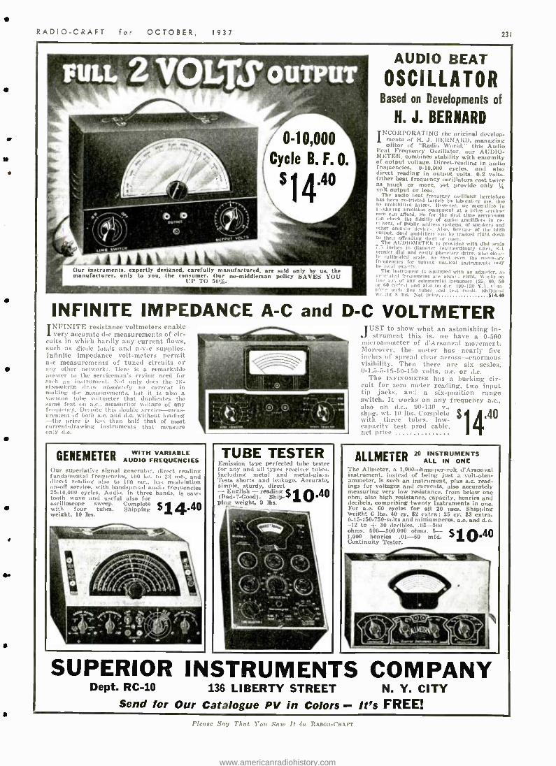
RADIO -CRAFT for OCTOBER, 1937 231
nu.
Our instruments, expertly designed, carefully manufactured, are sold only by us. the manufacturer, only to you, the consumer. Our no- middleman policy SAVES 101'
1'1' T(1
AUDIO BEAT
OSCILLATOR Based on Developments of
H. J. BERNARD INCORPORATING the original develop-
ments of H. J. BERNARD, managing editor of "Radio World," this Audio ltrat Frequency Oscillator, our AUDIO -
METER, combines stability with enormity of output voltage. Direct -reading in audio frequencies, 0- 10.000 cycles, and also direct reading in output volts, 0-2 volts. Other beat frequency oscillators cost twice as much or more, yet provide only % 'o!t output Or less.
The audio beat frequency oscillator heretofore t.is been restricted largely to laboratory use. duo t.. prohibitive prices. However. we mecialise in 1.tdueing prerision equipment at a price service- men afford. So for the first timo servieemon am check the fidelity of audio amplifiers in ro- relvers, of toddle address systems. of speakers and other acoustic deviir,. Also. hre.m e of the high output, dead amplifiers can he tracked right down to their offending short or open.
The ACDIOMI l-TElt is provided with dial scale - . niches in diaueter (extraordinary slat.), 8-1
` cl 'rnier dial and costly planetary drive, also ose- eallbrated scale. so that even san n tha tower.. .ire
gaeneies for tuning musical instrtmelds nit br read exactly.
The instrument is equipped with an adjuster. crated frequencies a always right- Wink(
of any mmerrlal Irequeney (93. /u. l,ti rs e..) and also on dr. 190 -130 V.1.
with five tubes d test end hip, s. S an ht N ILs. Nil prig, 914.4,1
INFINITE IMPEDANCE A -C and D -C VOLTMETER N1'INITE resistance voltmeter.; enable very accurate d -c measurements of cir-
cuits in which hardly any current flows, such as diode loads and a -v -c supplies. Infinite impedance volt -meters permit a -c measurements of tuned circuits or any other networks. Here is a remarkable answer to the serviceman's crying need for such an instrument. Not only does the IN- FINOMETER draw nbsolutrl!r no current in making d -c measurements, but it is also a vaetium tube voltmeter that duplicates the same feat on a.c., measuring voltage of any frequency. Despite this double service-meas- urement of both a.c. and d.c. without loading -the price is les, than half that of most cu rrent- drawing instruments that measure ,mly d.c.
GENFMETER AUDIO FREQUENCIES Our superlative signal generator, direct reading fundamental frequencies, 100 kc. tu 22 mc.. and direct reading also to 100 mc., has modulation on -off service, with bandspread audio frequencies 25- 10,000 cycles. Audio, in three band:, is saw- tooth wave and useful also for oscilloscope sweep. Complete with four tubes. Shipping weight. 10 lbs. $14.40
TUBE TESTER Emission type perfected tube tester for any and all types receiver tubes, including metal and metal-gin . s. Tests shorts and leakage. Accurat,, simple, sturdy, direct - English - reading $ r 0.40 (Bad - ?- Good). Ship- ping weight, 9 lbs.
, a -iii vl
JCST to show what an astonishing in- strument this is, we have a 0 -500
microammeter of d'Arsonval movement. Moreover, the meter has nearly five inches of spread clear across- enormous visibility. Then there are six scales, 0- 1.5- 5 -15 -50 -150 volts, a.c. or d.c.
The INFINOMETEIt has a bucking cir- cuit for zero meter reading, two input tip jacks, and a six- position range switch. It works on any frequency a.c., also
wt. 30
$ .40 sling. wt. 10 lbs. Complete with three tubes, low - capacity test prod cable, net price
ALLMEER 20 ALL INSTRUMENTS
ONE The Allmeter, n 1,000 -ohms -per -volt d'Arsonval instrument, instead of being just a volt -ohm- ammeter, is such an instrument, plus a.c, read- ings for voltages and currents, also accurately measuring very low resistance, from below one ohm, also high resistance, capacity, henries and decibels, comprising twenty instruments in one.
For a.c. 60 cycles for all 20 uses. Shipping weight 6 lbs. 40 cy. $2 extra: 25 cy. $3 extra. 0-15 -150- 750 -volts and milliamperes, a.c. and d.c. -12 to -1- 30 decibles..03 -500 ohms. 500 -500,000 ohms. 5- 1.000 henries .01 -50 mfd. Continuity Tester. $1. 0.40
41140
SUPERIOR INSTRUMENTS COMPANY Dept. RC -10 136 LIBERTY STREET N. Y. CITY
Send for Our Catalogue PV in Colors - It's FREE! 1'h'osr Say Thnt You Sr,,,- lt in Itnnirt- ('RAFT
www.americanradiohistory.com
232
Infinite Ohms Per Volt with
5gC. MODEL 4900
ZERO CURRENT
VOLTMETER
This instrument may be connected to grids in any circuit without dis- turbing operation of set, built -in power supply furnishes balancing voltage, -adequately filtered. This instrument indicates:
D.C. Volts at infinite ohms per volt
A.C. -D.C. Volts at 1000 ohms per volt
A.C. -D.C. Milliamperes Ohms and Megohms
Microfarads, Leakage Decibels
Henries Wide ranges assure complete cover- age for radio testing.
Model 49555
Universal Volt Ohm Milliammeter
Larger Meter - More Ranges
For Quality, Accuracy and Dependability use
HICKOK TEST INSTRUMENTS ZERO CURRENT VOLTMETERS
VOLT OHM MILLIAMMETERS SET TESTERS
TUBE TESTERS OSCILLATORS
OSCILLOGRAPHS MODULATORS
APPLIANCE TESTERS PANEL METERS
Write for literature on the complete I IICKC) line.
HICKOK ELECTRICAL INSTRUMENT CO.,
10413 Dupont Ave., CLEVELAND, OHIO
RADIO -CRAFT for OCTOBER, 1937
"LEARN -BY- EXPERIMENTING"
BEGINNERS' PRACTICAL RADIO COURSE
AUDIBLE TONE GENERATOR t e,1 from page 219)
Fig. A; and the corresponding symbols for these parts, in Fig. 1A.
EXPERIMENT -AUDIBLE TONE GENERATOR ( "RADIO WHISTLE ") OBJECT: To study the Operation of the
Vacuum Tube in Producing Audible Tones. known as audio fr/ vs,eney oscillations.
PRINCIPLES INVOLVED In this Experiment, the me r.,t inn of the vacuum
tube as an amplifier of an input signal is modi- fied so as to have the tube produce its own signal which can be heard in the phones. Such a "generator of tones" which can be heard may be called a "Radio Whistle" or more correctly an Audible Tone Generator.
The purpose for which each part, other than the tube, is used in this Experiment is explained in the following listing:
Rheostat (R). A moving arm making contact with resistance mire, that is, wire which opposes the passage of the electric current through it. By turning the rheostat knob to the right, we include less and less of this resistance in the circuit, and thus allow more current to flow.
Transformer (T). A unit consisting of 2 coifs of many turns per layer and many layers of insulated wire wound around an iron core. Cur- rent is sent through the first coil, called the primary (marked p and b in diagram. Fig. 2A and B). When this current is caused to change in any way, such as by electrical vibrations. these changes are transferred by the iron core to the second coil wound on it. called the sec- ondary (marked e and g, in diagrams). Although these 2 coils are in no way electrically connected, the fact that they are wound on the same core gives the result that any changing current in the primary winding produces corresponding changes in the secondary winding. When, as in this case, the number of turns of the secondary is much greater than the number of turns in the primary, the changes produced in the secondary are also much greater than the original changes in the primary. This accounts for the name "step -up" transformer, and, since it is used here in connection with audible sounds. it is technically known as an audio transformer.
Variable Condenser (C adj.). A condenser con- sists, in general, of 2 conducting plates (usually, of brass or aluminum) separated by an insulator (mica. air, etc.). Its effectiveness in any circuit is judged by the amount of its capacity. which means its ability to store an electric charge. In this case we can make the capacity greater by turning the adjustment screw to the right. which brings the 2 metal plates closer together, though they are still separated by the insulator which is a sheet of mica. Its use here is optional. since its effect of making the pitch lower, which is obtained by increasing the capacity, can be obtained without it, to a smaller degree, by using the rheostat to increase the filament cur- rent which (by indirectly effecting the "tube capacity") has the same effect.
Key (K). Has the same action as a pushbutton switch in closing a break in the circuit thus forming a complete path (e closed circuit) and allowing the current to flow.
Pitones (Ph.). A device for converting the vary- ing flow of electricity into audible sounds. This device will be considered in detail in the next Experiment.
Battery (lts V.). A unit composed of a num- ber of cells which generate electricity by chemical action. Each cell contains a zinc and carbon element operating in a chemical paste. Since this paste, though always moist. is not in liquid form, the cell is called a drycell. Such a drycell could, for example. light a small flashlight bulb. since each cell is rated at 11/2 volts, which signifies its effectiveness in supplying the "electric pressure" required to force the cur- rent through the circuit against the opposition or resistance of the wire in the bulb. By connect- ing 3 such cells, as shown in the diagram, we have a series connection and the voltage of the entire battery is then 41/2 V. (or volts). A "C" battery of 41/2 V. is simply a unit containing 3
Please Say That You Saw It in RADIO -CRAFT
small cells already connected internally, and thus is equivalent to 3 individual drycells of the same small size. Although larger cells will last longer, this size is sufficient, in this Experiment, for operation over a few months.
ANALYZING THE CIRCUITS OF A TUBE Referring to Fig. 211, let us trace the 3 circuits
of the tube in this arrangement. We will start with the "filament circuit" (or "loop "). The filament current which heats the tube is con- trolled by the rheostat. Turning the knob to the right decreases the amount of resistance of the rheostat being used, and so the current in the filament becomes greater, heating the fila- ment more.
The "grid circuit" contains the secondary winding of the transformer in which "electrical vibrations" (or oscillations) will be produced.
In the "plate circuit" when the key is pressed. plate current flows through the primary winding of the transformer setting up the electrical vibrations. These vibrations are transferred to the secondary winding in the grid circuit, be- cause -as previously stated-both primary and secondary coils are wound on the same iron core. These vibrations, in the grid circuit appear in turn, in amplified form, in the plate circuit- Since the plate circuit is continually feeding back energy to the grid circuit the electric vibrations do not die out but are sustained so as to be continuous at a certain rate (or frequency). For this reason this device may be called an "audible tone generator" or more technically an audio - frequency oscillator.
The sound in the headphones caused by these continuous vibrations can be controlled by the key to send signals in the International (or Con- tinental. as it is also called) Code, which is shown in Fig. 1H.
We can also change the pitch of this tone by adjusting either the rheostat or the optional ad- justable condenser. For example, by turning the rheostat knob to the right, the increased filament current causes a lower pitch; this same effect can be obtained to a greater degree by adding the greater capacity of the condenser to the cir- cuit. This lower pitch indicates that the vibra- tions are taking place at a lower frequency. The principle involved in this case is that in any such "oscillating circuit," if the characteristics of the coil (its inductance) are kept constant, the frequency of oscillation will then depend upon the amount of capacity (condenser effect) in the circuit; the frequency, and therefore the pitch, becoming lower as the amount of capacity is increased.
PROCEDURE AND RESULTS A -Code Signaling
(1) Assembling. The appearance of the part?, before and after mounting, is shown in the photographs. Figs. A and B. The wiring between these parts is shown pictorially in Fig. 2A and in symbol form (schematically) in Fig. 213.
(2) Wiring. In making connections by solder- ing (The reader is referred to the article "How to Solder" which appeared in the July, 1937, issue of Radio -Craft.) the order in which the connections are made should follow the plan, shown in Fig. 2A and B, an made up of the following 3 "loops' or circuits:
Filament Circuit -The wiring, starting from the binding post or connection terminal marked "A } ", will include the 2 terminals of the rheostat; "f +" and "f -" terminals of the socket into which the tube is later to be plugged; and back to the "A -" binding post.
Grid Circuit -The wiring, starting from the G terminal of the socket includes the g and e terminal; of the transformer secondary; and back to the "A -" binding post. If condenser C adj.. is used across the transformer secondary. leave one wire unconnected until later. After the set -up has been worked without it. it can then be connected to determine its effect on the circuit.
Plate Circuit -The wiring, starting from the p terminal of the socket includes the transformer primary p and b terminals; (NOTE: If any
1
i
s
s
www.americanradiohistory.com
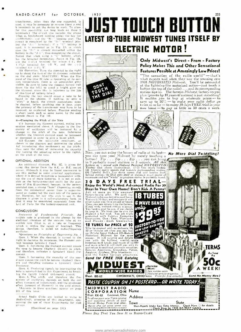
RADIO -CRAFT for OCTOBER,
transformer, other than the one used, it may be necessary to reverse these p and b terminals to get the device to work. To allow for this possibility. use long leads on these 2
terminals.) The circuit also includes the phone that is. headphone) binding posts; the key for
pushbutton) : and the "111 -" binding Post. The circuit is completed by the "ll -" terminal join- ing the "A--" terminal; if a "C" battery is used, it is connected as in Fig. 2A in which rase the "I3 -" is already connected within the battery to the "A t ", thus completing the circuit. Notice that when using a "C" battery, which has the terminal designation shown in Fig. 1A, use the ( -4t_) terminal for minus I -); the
' / ( -I) terminal for -( -3 V., a and the ( - ) terminal for 4 V.
(:3) Operation. Torn the rheostat to the right up to about the first of the 10 divisions indicated on the dial plate. (CAUTION: When the fila- ment of the type 30 tube is operating at it cor- rect temperature. there is no perceptible glow visible. lie sure to keep the rheostat turned well down Ito the left) to avoid a bright glow on the filament, since this is injurious to the life of this type of battery tube.)
Pressing the key should cause a note to be heard in the phones. If nothing, or only a "click" is heard, the circuit connections must he checked, before anything else is done, since the primary of the transformer may have to be reversed, as explained before. Practice sending a short word, such as some name, by the code signals shown in Fig. 1H.
13- Changing the Pitch of the Note (1) Increase the filament current, noting pre-
caution mentioned above. A change in the fre- quency of oscillation will be indicated by a change in the pitch of the note. Determine whether the filament current must be increased or decreased in order to give a lower pitch.
(2) Connect the adjustable condenser, as shown in the diagram and determine the effect (of introducing this condenser) on the pitch; then note the effect of increasing its capacity (by turning the adjusting screw to the right),
on the pitch of the tone.
OPTIONAL ADDITION An additional diagram, Fig. 1G. is given for
using this device from the A.C. or D.C. socket power. Although it may be found convenient to use this method in some practical applications, where it is desired to operate a loudspeaker with. out the use of more batteries, it is not as suit- able as the battery-operated outfit for the pur- pose of this Experiment, because, in the power - operated case, a strong "hum" I humming sound) from the commercial power lines is superim- posed on (added to) the pure note of the genera- tor. However, for any who wish to use it, the diagram is given in a self- explanatory form, so that it may he considered separately from the List of Parts for the battery -operated unit.
CONCLUSION ,star,. II t o, Fundamental Principle. An
audible note is produced in the phones by the electrical vibration of the vacuum tube at an audible rate (that is, at a rate or frequency which is within the range of hearing). This device, therefore, is called an audio -frequency oscillator.
Questions on Principles of Experiment No. I Ques. 1. When the rheostat is turned to the
right to decrease its resistance, the filament cur- rent becomes (greeter) (less).
Ques. 2. Increasing the filament current causes the tone to become (higher) (lower) in pitch. and therefore, indicates a (greater) (less) fre- quency.
Ques. 3. Increasing the capacity of the con- denser causes the pitch to become ( higher) (low- er) and therefore indicates a (greater) (less) frequency.
piles. 4. Producing signals by interrupting the note is accomplished in this Experiment by break- ing the (grid) (Plate) (filament) circuit.
Qnes. 5. The pitch. and therefore the fre- quency of oscillation depends on berth the coil effect (amount of inductance). and the condenser effect (amount of filament) in the grid circuit.
Answers to these questions appear un page 241 of this issue.
School Radio Clubs are invited to write to Radin -!'raft. attention of this department. con- cerning the use of these Experiments for club gr mq's.
(Continued on page 241)
115T TOUCH BUTTON LATEST I8-TUBE MIDWEST TUNES ITSELF BY
ELECTRIC MOTOR! Only Midwest's Direct - From - Factory Policy Makes This and Other Sensational Features Possible at Amazingly Low Prices! "The sensation of the radio world " - that's
list experts said when they saw the amazing new 1')38 MOTORIZED Midwest. You'll be astounded at the lightning -like motorized action -just touch a button (on top of the radio) ... and its corresponding station zips in. The famous Midwest factory -to -you plan (proven by 18 years of success) is just as exciting! It enables you to buy at wholesale prices - to save up to 50% - to make your radio dollar go twice as as far - to enjoy 30 days FREE trial in your own home - to pay as little as 50 cents a week.
Now, you can enjoy the luxury of radio at its best- No More you can tune your Midwest by merely touching ;t button! Zip . Zip . Zip . .. you can brtn f T .
in 9 perfectly tuned stations in 3 seconds. All this happens in'¡ second with Midwest Perfected MOTORIZED Tuning: (Sec above illustrations). (1-2) You touch button: (3) Electric motor speeds dial towards corresponding station: (4) Colorful Dull's Eye darts across dial and locales itself behind station: (5) Dial stops itself at station's exact center of resonance and eye "winks" as program cures in perfectly tuned.'
30 DAYS FREE TRIAL - Enjoy the World's Most Advanced Radio For 30 Days In Your Own Home! Don't Risk A Penny' Act at once on this unusual factory -to -you offer. We send a Midwest radio you desire to your home. You use it 50 days, and compare it with other radios you have owned or heard. Then, you can return it to the factory, if you wish, without risking a penny. You have a year top y, if you decide to keep it. We trust you to give the Midwest a fair trial. You are triply protected with Foreign Reception Guarantee, One - Ycar Warranty and Money - Back Guarantee
18 TUBES
Dial Twiddling!
B WAVE BANDS
49 g5 04"
18 TUBES for PRICE of 10 AC10a . sf Pgi" \1' by he content with an ordinary lo, F íO1:
(' 12 or 14 -tube set when you can tiny NEW 515 I Motorized
Super Datum 1theEe same
e CMA$Bti5 $r
money. It will uprise and delight 'ESr_ you with its brilliant world - wide- -, reception on 6 bands, and range of 12,001 and more miles! It will thrill you with its
marvelous 6-continent overseas reception. Secures American, Canadian, Police, Amateur, Airplane, Ship broadcasts .. .
and the finest foreign programs. Send for FREE 1938 Catalog
N Dept. EE -12
TERMS
D W E S T Sery/oe Men: Join nation-wide Midwest service organira. jj
CINCINNATI, OHIO ion. Write for free details.J
WORLD -WIDE RADIOS
As Low As
50c A WEEK!
Send No Money Now:
PASTE COUPON ON 10 POSTCARD - OR WRITE . TODAY.
MIDWEST RADIO CORPORATION Name Dept. EE -12 Cincinnati, Ohio Send me your new Fuse catalog Address
d complete details of and 30 -day Fuca trial otter. Town State
rspectal offer and Prier. pren rntr User -Agents Make Easy Extra Money. Check Here . I For details asset dratipe direct with r.ewrr armut.> ¡1 Check Here for 1938 BATTERY Cetelo
Please Say That You Saw It in RADIO-CRAFT
www.americanradiohistory.com
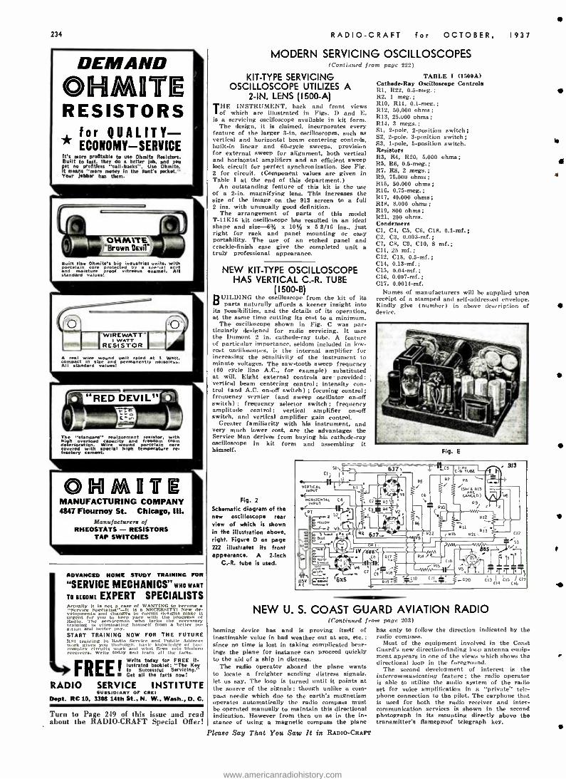
234
DEMAND OGli //u04C RESISTORS
for QUALITY- * ECONOMY - SERVICE It's more profitable to use Ohmlte Resistors. Built to last. they do a better job. and You pet ne profitless "call- backs ". Use ohmite. It means "more money in the pant's pocket." Your jabber has them.
B uiltlike Ohmite's big ustri units. with lain isturr of vitreous ,enamel.
a All
standard values!
o s wound unit t at iWatt. inect in m: e l noiseless.
All standard values! vlus!
The "standard" replacement
en
resistor with higyh overload rapacity and edom from deterioration. Wire wound porcelain core
f rBry with ial high temperature e
O Y VITIE MANUFACTURING COMPANY 4847 Flournoy St. Chicago, III.
Manufacturers of RHEOSTATS - RESISTORS
TAP SWITCHES
ADVANCED HOME STUDY TRAINING FOR
"SERVICE MECHANICS" WHO WANT
TO BECOME EXPERT SPECIALISTS Actually it is tacase of WANTING to become a
Specialist-It is a NECESSITY! New de- velopments mid Glandes to circuit designs make it rient for you to keep pace the progress of
Radio. The a rvlreman Who lacks the leresxary training is eliminating himself from a better po- sition and hotter pay. START TRAINING NOW FOR THE FUTURE 1151 training In Radio 5 and Public Address work gives you thorough, bas knowledge of how complex tits work , mi what goes in muden, ,a,a,vrs
circuits tuna and learn all the facts.
FREE!yóetralld°es
RADIO SERVICE INSTITUTE SUBSIDIARY OF CREI
Dept. RC 10, 3308 14th St., N. W., Wash., D. C.
Turn to Page 2 t9 of this i -cue and read about the RADIO -CRAFT Special Offer!
RADIO -CRAFT for OCTOBER,
MODERN SERVICING OSCILLOSCOPES (Continued from pape 222)
KIT -TYPE SERVICING OSCILLOSCOPE UTILIZES A
2 -IN. LENS (1500 -A) THE INSTRUMENT, back and front views
of which are illustrated in Figs. D and E, is a servicing oscilloscope available in kit form.
The design, it is claimed, incorporates every feature of the larger 3 -in. oscilloscopes, such as vertical and horizontal beam centering controls, built -in linear and 60 -cycle sweeps, provision for external sweep for alignment, both vertical and horizontal amplifiers and an efficient sweep lock circuit for perfect synchronization. See Fig. 2 for circuit. (Component values are given in Table I at the end of this department.)
An outstanding feature of this kit is the use of a 2 -in. magnifying lens. This increases the size of the image on the 913 screen to a full 2 ins. with unusually good definition.
The arrangement of parts of this model T -11K16 kit oscilloscope has resulted in an ideal shape and size -6% x 10t/2 x 5 3/16 ins., just right for rack and panel mounting or easy portability. The use of an etched panel and crackle -finish case give the completed unit a truly professional appearance.
NEW KIT -TYPE OSCILLOSCOPE HAS VERTICAL C.-R. TUBE
(I 500 -B) BUILDING the oscilloscope from the kit of its
parts naturally affords a keener insight into its possibilities, and the details of its operation, at the same time cutting its cost to a minimum.
The oscilloscope shown in Fig. C was par- ticularly designed for radio servicing. It uses the Dumont 2 in. cathode -ray tube. A feature of particular importance, seldom included in low - cost oscilloscopes, is the internal amplifier for increasing the sensitivity of the instrument to minute voltages. The saw -tooth sweep frequency (60 cycle line A.C., for example) substituted at will. Eight external controls are provided: vertical beam centering control; intensity con- trol (and A.C. on-off switch) ; focusing control; frequency vernier (and sweep oscillator on -off switch) ; frequency selector switch; frequency amplitude control; vertical amplifier on-off switch, and vertical amplifier gain control.
Greater familiarity with his instrument, and very much lower cost, are the advantages the Service Man derives from buying his cathode -ray oscilloscope in kit form and assembling it himself.
Fig. 2
Schematic diagram of the new oscilloscope rear view of which is shown in the illustration above, right. Figure D on page 222 illustrates ifs front appearance. A 2 -inch
C.-R. tube is used.
1937
TABLE i (1500A) Cathode -Ray Oscilloscope Controls RI, R22, 0.5 -meg.: R2. 1 meg. ;
R10, R11, 0.1 -meg.; R12, 50,000 ohms; R13, 25,000 ohms; R14, 3 megs.; SI. 2 -pole, 2- position switch; S2, 2 -pole, 3- position switch; S3, I -pole, 5- position switch. Resistors R3, R4, R20, 5,000 ohms; R5, R6, 0.5 -meg. ;
R7, R8, 2 megs.; R9, 76,000 ohms; R15. 50,000 ohms; R16, 0.75-meg.; R17. 40,000 ohms; Rit. 8,000 ohms; R19, 800 ohms; R21, 200 ohms. Condensers Cl, C4, C5, C6. C18, 0.1 -mf.; C2. C3. 0.003 -mf.; C7, CR. C9, C10, 8 ml.; C11, 25 mf.; C12, C13, 0.5 -mt.; C14, 0.13-mf.; C15, 0.04-mf.; C16. 0.007-mf.; C17. 0.0014 -mf.
Names of manufacturers will be supplied upon receipt of a stamped and self -addressed envelope. Kindly give (number) in above description of device.
Fig. E
NEW U. S. COAST GUARD AVIATION RADIO (Continued from pape 203)
homing device has and is proving itself of inestimable value in bad weather out at sea, etc.: since no time is lost in taking complicated bear- ings the plane for instance can proceed quickly to the aid of a ship in distress.
The radio operator aboard the plane wants to locate a freighter sending distress signals, let us say. The loop is turned until it points at the source of the signals; though unlike a com- pass needle which due to the earth's magnetism operates automatically the radio compass must be operated manually to maintain this directional indication. However from then on as in the in- stance of using a magnetic compass the plane
Please Say That You Saw It in RADfo -CRAFT
has only to follow the direction indicated by the radio compass.
Most of the equipment involved in the Coast Guard's new direction- finding loop antenna equip- ment appears in one of the views which shows the directional loop in the foreground.
The second development of interest is the intercommunicating feature; the radio operator is able to utilize the audio system of the radio set for voice amplification in a "private" tele- phone connection to the pilot. The earphone that is used for both the radio receiver and inter- communication services is shown in the second photograph in its mounting directly above the transmitter's flameproof telegraph key.
t
www.americanradiohistory.com
RADIO -CRAFT for OCTOBER,
NEW CIRCUITS IN MODERN RADIO RECEIVERS
(Continued from page 211)
Up to 3 V. peak signal across the last I.F. secondary (51) the receiver operates normally without A.V.C. at maximum sensitivity. When a peak exceeding -i -3 V. reaches the lower diode plate through the coupling capacity (50), this diode will start drawing current, building all A.V.C. voltage across the 1 -mesa. diode load resistor (61) and the 0.33 -meg. tiller resistor. At the junction of the (61 and 5s) about % of the total A.V.C. developed is conveyed to the control -grid of the 667G I.F. amplifier. The total is conducted to the other grids through resistance -capacity filters. (6) Suppressor Volume Expander
General Electric Model F -53. Making use of an ordinary triode power detector as the 2nd - detector as shown in Fig. 1F, advantage is taken of the fact that the cathode becomes posi- tive in proportion to the average modulation intensity of the signal. The cathode is, there- fore, connected to the suppressor -grid of the I.F. amplifier and as it becomes more positive, the signal is given additional amplification. When the signal is lower. the amplification is decreased and volume expansion is accom- plished by varying the amplification in propor- tion to the signal strength. (7) Noise- Limiter Circuit
General Electric Model E -155. This receiver makes use of an additional 6116 tube to function for delay bias in A.V.C. and a noise -limiter cir- cuit. See Fig. 1G. The signal voltage is taken from the 2nd -detector diode load nt the jttnc- tion of R21 and R22. the drop across R21 being the desired signal. This is fed to the first audio amplifier through a diode plate circuit (11 -13). coupling condenser TC -55 and volume control R31.
The cathode of section (11 -13) of the 6H6 noise limiter is maintained somewhat more negative than the plate of the same section due to its connection at a more negative point in the 2nd -detector load and hence a constant cur- rent flows in this diode circuit as soon as any signal is tuned -in. This current may rise to a predetermined maximum allowing full volume output, but at this point the diode is drawing near -saturation current. A noise impulse or any signal disturbance having greater ampli- tude will drive the diode into saturation. Above this point to reasonable limits, all additional signal drop will occur across the diode and hence be diverted from the A.F. system as the saturation current tends to remain constant in spite of increased plate voltage.
In this way any noise which is above the desired signal level is effectively eliminated.
ra
Well. fellows. how do you like this new de- partment in Radio.('raft? Constructive criticisms will be mutually advantageous.
RADIO WITTIQUIZ (Continued frum pay' _ 1;)
Answers (10,) 11311 (16h) (lid) a Ill (17d) (12d) i :u.) (19b)
Contest Rules (1) An award of a 1 -year subscription to
Radio -Craft will be given to each person who submits a WITTIQUIZ that the Editors con- sider suitable for publication in Radio- Craft.
(2) WITTIQUIZZES must be typed; use only one side of paper.
(3) Submit as many WITTIQUIZZES as you care to -the more you submit the more chance you have of winning -but each should be good.
(-1) Each WITTIQUIZ must incorporate humorous elements, and must be based on some term used in radio, public address or electronics.
(5) All answers must be grouped, by tntes- tion number and correct- answer letter, on a separate sheet of paper.
(6) All contributions become the property of Radio -Craft. No contributions can be returned.
(7) This contest is not open to Radio -Craft employees or their relatives.
(M) The contest for a given month closes on the 15th of the 3rd month preceding magazine - issue date. (For instance, contributions to De- cember, 1937, Radio- Craft, on the newsstands about Nov. 1, must be received at Radio-Craft editorial offices not later than Sept. 15th, 1937.)
1937 235
$ 01)11°Z PRIZES OPEN TO
EVERYONE .
642 THE $1,000
CONTEST
rs4W
LET THIS Weer ?Axe, /938 WHOLESALE/MD/0 CATALOG deft/ fot iiow TO
WIN ONE OF THE PR /ZES
FIRST PRIZE
SECOND PR) ' $250
TMRD PRIZE $150 toy elk"' ,, ''' :'$100
$10, Jri: OD
$S00
Open to everyone ... servicemen ... amateurs .. engineers ... experimenters. So simple anyone can win! Complete details on how to o 'lain these valuable prizes found on Page ONE of the BIGGEST CATALOG IN RADIO HISTORY. Send for it immediately and get your slice of the generous awards. You can't afford to miss this wonderful opportunity! Be one of the winners ... clip the convenient coupon now! The following well known people in the radio industry trill act as judges: Dr. O. H. Caldwell ... Editor, Radio Today; Mr. Law Cochaday ... Edit", Radio News; Mr. Joseph Reiss ... President, Reiss Adverti.teg Agency.
EVERYONE!! HURRY!! Here's your lucky a'? o..Y
chance to win one of the valuable prizes we are offering! f. Here's your opportunity to obtain our wonderful catalog. It's FREE!! And its contents will prove invaluable to you!
HERE'S THE GREATEST
CATALOG IN RADIO for the SERVICER ... The greatest collet- '
. its the biggest ... the best ... and
rtea*\ lion of up- to-date test equipment ... 1 over 10,000 bargains in parts, tubes,
\t ' hardware ... at prices that cannot be
A\ tibeaten! See this catalog ... learn why
1\ thousands of successful servicemen buy the WHOLESALE way.
for the SOUND ENGINEER... Lafayette P.A. systems are made in all sizes for every possible requirement and speci- fication ... at prices that allow a handsome margin of profit. Complete beautiful NEW line described in de- tail in BIG P.A. section.
for the AMATEUR ...Thousands of "Hams" buy the WHOLESALE way! It's the easiest ... the swiftest ... most re- liable . and economical way. WHOLESALE maintains the biggest complete stocks of standard equip- ment to be found anyullerc.
it has more radio bargains packed between its covers than ever before! Imagine ... more than 10,000 real radio "Buys" . at amazingly low prices! Thousands of radio parts .. at lowest listings ... offered by the World's Larg- est Radio Supply House! And NOW you can make your purchases by the WHOLESALE Easy Payment Plan. Use
your equipment as you pay for it.
gjanfanbRit, !! ... THIS CATALOG is 180 pages BIG ... and it's FREE! Send for it today ... get the details of the 51,000.00 con- test. See the new EASY -TO -PAY Plan now available.
SEND THE COUPON i/O*
01R0«SM P0010 NEWYORK,N.Y. CHICAGO,ILL. ATLANTA, GA. 1 0 0 SIXTH AVENUE 901 W. JACKSON BLVD. 430 W. PEACHTREE ST., N. W. BOSTON, MASS. BRONX, N. Y. NEWARK, N. J. JAMAICA, L. I,
WHOLESALE RADIO SERVICE CO., Inc. 100 Sixth A , Nw York, N. Y.
Rush FREE 1938 Catalog No. 69 -3K7.
Name - Address__
State _- City
Plea se .Tay 7'1,,r Yo re .,,>,' f, ,, ! ;put- lit -tt
E
KS*" Ws144 c47,.
MI
www.americanradiohistory.com
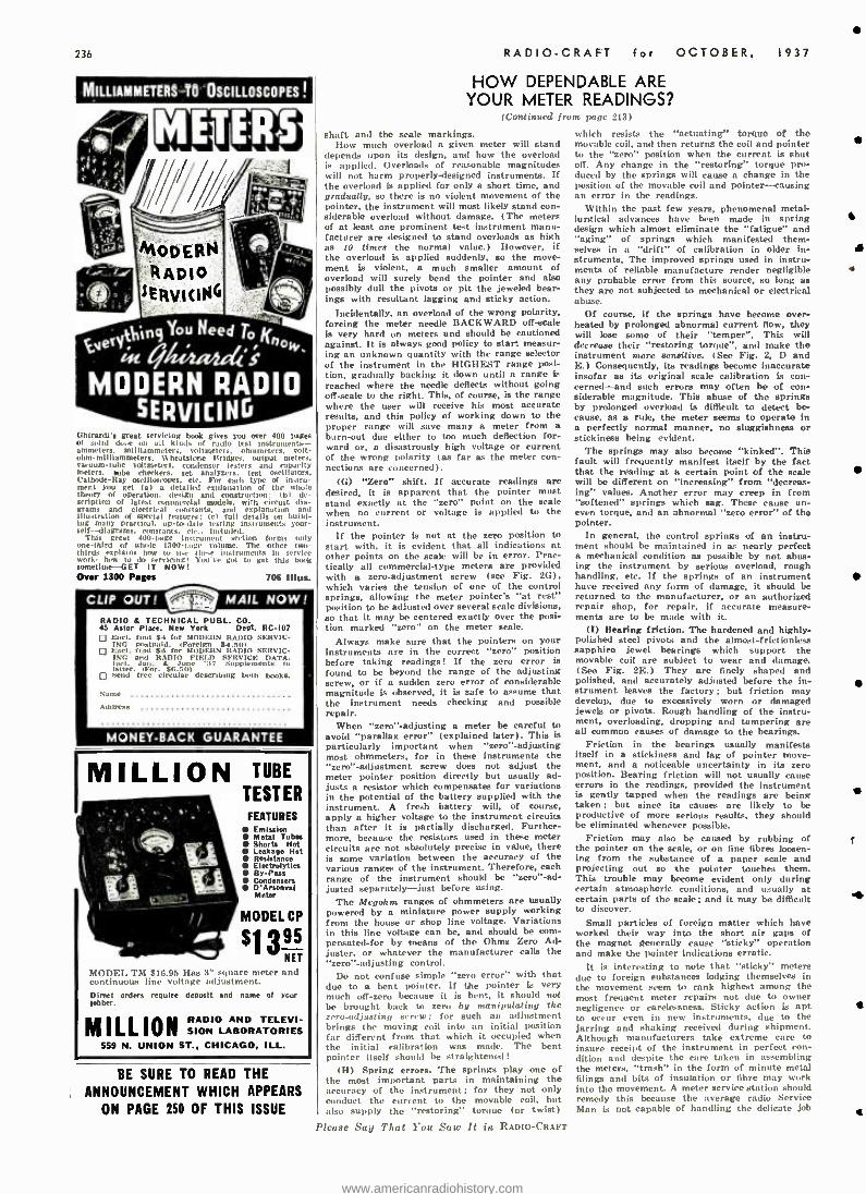
236
MILLIAMMETERS TO OSCILLOSCOPES !
(;hlrardi's great, set, hang look gives you over 400 pages of solid dose u all kinds o nr f radio test instruente- ammeters. milliammeten, voltmeters. ohmmeters. volt - ohm- nillllammeters. tCheatstone Bridges. output meters, vacuum -tube voltmeters, condenser testers and capacity meters. tube checkers, set analyzers, test oscillators, Catlssle -Ray oscilloscopes, etc For each type of Instru- ment you get (a) a detailed explanation of the whole theory of operation, design and construction : tb) de- scription of latest commercial models. with circuit dia- grams and electrical m.aants, and explanation and illustration or special features; Ici full details ml build- ing many prat( ira!, up -to -date testing instruments your - self- nllagrams, constants, etc.. included.
This great 400 -page instrument section forms only one -third of whole 1300 -page volume. The other two- thirds explains how to toe for -e instruments In s ry lee work- brew to do rvu-u ts'! Votg,o got to get this book sometime GET IT NOW Over 1300 Pages 706 Illus.
CLIP OUT! '0'. MAIL NOW!
RADIO & TECHNICAL PUBL. CO. 45 Astor Place. New York Dept. RC -I07
Encl. find $4 for MODERN RADIO SERVIC- ING postpaid. (Foreign $4.501 Encl. find $0 for MODERN RADIO SERVIC- ING and RADIO FIELD SERVICE DATA. Incl. J
Far. $e 6 dr Supplements to 01
D Send free circular describing both books.
Name
Address
MONET -BACK GUARANTEE
MILLION TUBE
TESTER FEATURES
Emission Metal Tubas Shorts Hot Leakage Hat Resistance Electrolytirs By -Pass Condensers D'Arsonval Meter
MODEL CP
$1395 NET
MODEL TM $16.05 Has 3" square meter and continuous line voltage adjustment. Direct orders require deptslt and name of ycur jobber.
MILLION RADIO AND TELEVI- SION LABORATORIES
559 N. UNION ST., CHICAGO, ILL.
BE SURE TO READ THE
ANNOUNCEMENT WHICH APPEARS
ON PAGE 250 OF THIS ISSUE
RADIO -CRAFT for OCTOBER, 1937
HOW DEPENDABLE ARE YOUR METER READINGS?
(Continued front page 213)
shaft and the scale markings. How much overload a given meter will stand
depends upon its design, and how the overload is applied. Overloads of reasonable magnitudes will not harm properly - designed instruments. If the overload is applied for only a short time, and gradually, so there is no violent movement of the pointer, the instrument will most likely stand con- siderable overload without damage. (The meters of at least one prominent test instrument manu- facturer are designed to stand overloads as high as JO times the normal value.) However, if the overload Ls applied suddenly, so the move- ment is violent, a much smaller amount of overload will surely bend the pointer and also possibly dull the pivots or pit the jeweled bear- ings with resultant lagging and sticky action.
Incidentally, an overload of the wrong polarity, forcing the meter needle BACKWARD off -scale is very hard on meters and should be cautioned against. It is always good policy to start measur- ing an unknown quantity with the range selector of the instrument in the HIGHEST range posi- tion, gradually backing it down until a range is reached where the needle deflects without going off -scale to the right. This, of course, is the range where the user will receive his most accurate results, and this policy of working down to the proper range will save many a meter from a burn -out dice either to too much deflection for- ward or, a disastrously high voltage or current of the wrong polarity (as far as the meter con- nections are concerned).
(G) "Zero" shift. If accurate readings are desired, it is apparent that the pointer must stand exactly at the "zero" point on the scale when no current or voltage is applied to the instrument.
If the pointer is not at the zero position to start with. it is evident that all indications at other points on the scale will be in error. Prac- tically all commercial -type meters are provided with a zero- adjustment screw (see Fig. 2G), which varies the tension of one of the control springs, allowing the meter pointers "at rest" position to be adjusted over several scale divisions, so that it may be centered exactly over the Posi- tion marked "zero" on the meter scale.
Always make sure that the pointers on your instruments are in the correct "zero" position before taking readings! If the zero error is found to be beyond the range of the adjusting screw, or if a sudden zero error of considerable magnitude is observed, it is safe to assume that the instrument needs checking and possible repair.
When "zero " -adjusting a meter be careful to avoid "parallax error" (explained later). This is particularly important when "zero"-adjusting most ohmmeters, for in these instruments the "zero"-adjustment screw does not adjust the meter pointer position directly but usually ad- justs a resistor which compensates for variations in the potential of the battery supplied with the instrument. A fresh battery will, of course, apply a higher voltage to the instrument circuits than after it is partially discharged. Further- more, because the resistors used in these meter circuits are not absolutely precise in value, there is some variation between the accuracy of the various ranges of the instrument. Therefore, each range of the instrument should be "zero " -ad- justed separately -just before using.
The Mcgohm ranges of ohmmeters are usually powered by a miniature power supply working from the house or shop line voltage. Variations in this line voltage can be, and should be corn - pensated -for by means of the Ohms Zero Ad- juster, or whatever the manufacturer calls the "zero"- adjusting control.
Do not confuse simple "zero error" with that due to a bent pointer. If the pointer is very much off -zero because it is bent, it should not be brought back to zero by manipulating the zero- adjusting screw: for such an adjustment brings the moving coil into an initial position for different from that which it occupied when the initial calibration was made. The bent pointer itself should be straightened!
(H) Spring errors. The springs play one of the most important parts in maintaining the accuracy of the instrument; for they not only conduct the current to the movable coil, but also supply the "restoring" torque (or twist)
Please Say That You Saw It in RADIO -CRAFT
which resists the "actuating" torque of the movable coil, and then returns the coil and pointer to the "zero" position when the current is shut off. Any change in the "restoring" torque Pro- duced by the springs will cause a change in the position of the movable coil and pointer -causing an error in the readings.
Within the past few years, phenomenal metal- lurgical advances have been made in spring design which almost eliminate the "fatigue" and "aging" of springs which manifested them- selves in a "drift" of calibration in older in- struments. The improved springs used in instru- ments of reliable manufacture render negligible any probable error from this source, NO long as they are not subjected to mechanical or electrical abuse.
Of course, if the springs have become over- heated by prolonged abnormal current flow, they will lose some of their "temper ". This will decrease their "restoring torque", and make the instrument more sensitive. (See Fig. 2, D and E.) Consequently, its readings become inaccurate insofar as its original scale calibration is con- cerned -and such errors may often be of con- siderable magnitude. This abuse of the springs by prolonged overload is difficult to detect be- cause, as a rule, the meter seems to operate in a perfectly normal manner, no sluggishness or stickiness being evident.
The springs may also become "kinked ". This fault will frequently manifest itself by the fact that the reading at a certain point of the scale will be different on "increasing" from "decreas- ing" values. Another error may creep in from "softened" springs which sag. These cause un- even torque, and an abnormal "zero error" of the pointer.
In general, the control springs of an instru- ment should be maintained in as nearly perfect a mechanical condition as possible by not abus- ing the instrument by serious overload, rough handling, etc. If the springs of an instrument have received any form of damage, it should be returned to the manufacturer, or an authorized repair shop, for repair, if accurate measure- ments are to be made with it.
(I) Bearing friction. The hardened and highly - polished steel pivots and the almost -frictionless sapphire jewel bearings which support the movable coil are subject to wear and damage. (See Fig. 2E.) They are finely shaped and polished, and accurately adjusted before the in- strument leaves the factory ; but friction may develop, due to excessively worn or damaged jewels or pivots. Rough handling of the instru- ment, overloading, dropping and tampering are all common causes of damage to the bearings.
Friction in the bearings usually manifests itself in a stickiness and lag of pointer move- ment. and a noticeable uncertainty in its zero position. Bearing friction will not usually cause errors in the readings, provided the instrument is gently tapped when the readings are being taken; but since its causes are likely to be productive of more serious results, they should be eliminated whenever possible.
Friction may also be caused by rubbing of the pointer on the scale, or on fine fibres loosen- ing from the substance of a paper scale and projecting out so the pointer touches them. This trouble may become evident only during certain atmospheric conditions, and usually at certain parts of the scale; and it may be difficult to discover.
Small particles of foreign matter which have worked their way into the short air gaps of the magnet generally cause "sticky" operation and make the pointer indications erratic.
It is interesting to note that "sticky" meters due to foreign substances lodging themselves in the movement seem to rank highest among the most frequent meter repairs not due to owner negligence or carelessness. Sticky action is apt to occur even in new instruments, due to the jarring and shaking received during shipment. Although manufacturers take extreme care to insure receipt of the instrument in perfect con- dition and despite the care taken in assembling the meters, "trash" in the form of minute metal filings and bits of insulation or fibre may work into the movement. A meter service station should remedy this because the average radio Service Man is not capable of handling the delicate job t
www.americanradiohistory.com
RADIO -CRAFT for OCTOBER,
of cleaning out ;, riti adjusting t he nu t veme n t. Anyway, the usual manufacturer's guarantee will generally cuver the cost of the adjustment, if it becomes necessary, within about 00 days of the purchase date.
A "sticky" meter may be detected immediately. Sticky or defective meters should be repaired at once rather than "borne with" as a man who uses an instrument which is not in 100(4, working order will subconsciously build up a psychological "mad" at the instrument's manufacturer. If it i repaired. he soon forgets that there was any- thing wrong with it.
"Backlash" in the moving parts is due primarily to loose fits in them. This trouble is not common. nor serious, since errors due to it may be ma- terially reduced by gently tapping the instru- ment while taking the readings.
(J) Electrical troubles. Under this classifica- tion are those troubles which may develop in the electrical circuits of the instrument after it has been assembled, tested and calibrated. Poorly- soldered joints, loose or broken conductors, and partial or complete "short- circuits" or "grounds" are some of them. It is surprising how many loose or badly -soldered joints develop in supposedly well -made instruments, unless the manufacturers are careful to inspect them rigidly at the factory.
"Opens" due to breakage of the fine wire comprising the movable coil or that employed for the multiplier resistors in voltmeters. have given trouble in some models of instruments. Of course, in such cases, the meter fails to operate either on one or more ranges -or altogether, so the trouble quickly makes itself evident. These electrical troubles can usually be detected by observation of the instrument for erratic action. When they are detected, they usually require a careful and complete repair before the instru- ment can again be considered reliable for service.
The copper-oxide rectifiers used in rectifier type A.C. instrument can cause an increase in meter inaccuracy. These copper -oxide rectifiers are inherently delicate and can be easily over - oaded. The average rectifier of this type will
pass a maximum of but a few milliamperes, above which the rectifier "breaks down." This condition appears to be present in any A.C. measuring -meter circuit whether it be strictly a series- dropping resistor type or one in which condensers and resistors are used. Care should therefore be exercised in the application of A.C. voltages to these meters, for overload often re- sults in a damaged rectifier and lowered A.C. voltage readings. The rectifiers cannot be re- paired and are never guaranteed by the original manufacturer. Therefore, damaged rectifiers .hould be replaced by the instrument manufac- turer, or by some reliable meter repair firm, for they sometimes go bad even while being placed in the instrument. The copper -oxide rectifiers should never be touched with the hands as chemicals in one's perspiration will usually cause early rectifier failure.
The ratio of the rectified current to the applied current may change for a given rectifier. Troubles such as the above cause this ratio to crop to sometimes half the original ratio. Varia- tions are also possible due to variations of tem- lerature, humidity and the amount of current applied to the rectifier each time it is used for a measurement. In other words, the rectifier will have one ratio when say 0.1 -ma. is applied, another when 0.5 -ma. is applied. etc.
(K) Magnet weakened. Properly- designed per- manent magnets of the types which are being used in recent high -grade instruments will stand a surprisingly large amount of rough handling before their magnetic strength will change s rficiently to result in incorrect readings. Other parts, such as the jewels and pivots, springs, e .G, which are more susceptible to damage by mechanical shock, are more troublesome in this respect. However, the safe rule is to handle your instruments carefully and avoid all mechanical jolts and shocks. (3) Inaccuracies Due to Way Instrument Is Used, Or Conditions Under Which Measurements Are Made
There are several inaccuracies which are apt to creep into measurements made with electrical instruments simply because of the way the in- strument is used, or the conditions under which the measurements are made. Errors which may be present when a particular instrument is used for one measurement may not occur when it is used again under different operating condi- tions -and vice versa! Some things to watch for will be pointed out in Part fl.
(Continued on page 247)
1937 237
.... e endorsed By Leading Service Organizations
* * HIGHEST QUALITY
* HIGHEST PROFIT
* * FREE EQUIPMENT
NATIONAL UNION RADIO TUBES
National Union manufactures a complete line of radio tubes -glass, metal and G -type. National Union's high quality has made them outstanding favorites in the radio service profession. All sales policies have been formulated with the idea of making National Union radio tubes the ideal replacement tube for the radio dealer. This has been backed up with a selling program that means real support and help to the wide -awake dealer. Deal- ers and jobbers handling National Union radio tubes are the leaders in repair parts and service.
Free Equipment Includes: Tube testers, set analyzers, oscillographs, signal generators, modulators, meters and other servicing instruments. In shop equipment items available include stock cabinets, coats, display signs, electric clocks, etc. All items absolutely free the National Union Way.
THE ROAD TO BETTER BUSINESS
1 . Full guarantee on 4. N. U. jobber stocks highest quality ore complete...No radio tubes. hunting for odd
2. Cut price business not solicited.
3. Price Protection.
types.
5 Timely business building aids.
FRF LATEST
CATALOG
This "Sign of Efficiency" Can Help You, Too.
Get It - FREE from N. U.
The NATIONAL UNION WAY ... Through National Union's help, radio service dealers everywhere have been able to set up better equipped shops to do better work ; also to obtain mer- chandise helps that produce more cus- tomers. National Union has constantly put the latest advances in scientific equipment as well as modern selling aids within reach of the service dealer. The National Union Deal calls for a dealer deposit which is rebated when the specified number of tubes has been purchased. Over 70,000 completed deals. Every service deader should investigate.
Clip ! Mail Now !
NATIONAL UNION RADIO CORPORATION 570 Lexington Ave., Net. York City -Tell me how to get the Sign of Eabdenry Free. - --I am also interested in the following equipment
Name
Address
NOW-WATER SAVINGS THAN EVER
CONTAINING HUNDREDS >Ei AC-
OF AMAZING jCßS01110 0HEs
RADIO VALUES AT NEW
LOW PRICES
IN NEW RADIOS AND EQUIPMENT We Carry Almost Every Radio Set Made (. - _ -_
TREMENDOUS DISCOUNTS On Tubes, Amplifying Equipment,
Public Address Systems, Auto, Home, and Farm Radios in all Styles, Types,
and Voltages. We can supply you with any Manufactured Set.
ALL MERCHANDISE GUARANTEED Factory Sealed Cartons. No Seconds
CHOICE EXCLUSIVE TERRITORY AVAILABLE TO LIVE REPRESENTATIVES
POST RADIO CORP. DEP'TQN W ORK,NC
Please Say That You Saw It in RADIO-CRAFT
67M1 1938
AUTO SET LIST $54.95
50', OFF
www.americanradiohistory.com
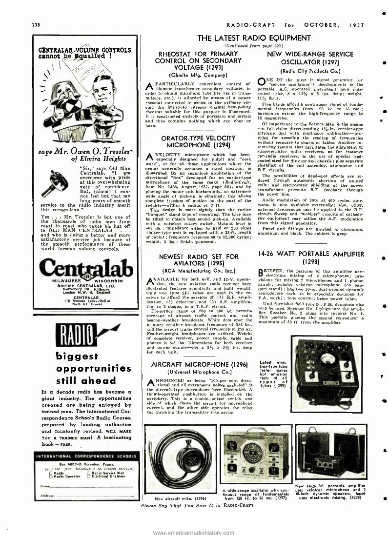
238
CENTRALAB VOLUME CONTROLS cannot be $anall !
says Mr. Owen O. Tressler' of Elmira Heights
"Sir," says Old Man Centralab, "I am overcome with pride at this overwhelming vote of confidence. But, (ahem) I can- not feel but that my long years of smooth
service to the radio industry merit this recognition." Yes . Mr. Tressler is but one of the thousands of radio men from coast to coast who takes his hat off to OLD MAN CENTRALAB . . . .
and who is doing a better and more satisfactory service job because of the smooth performance of these world famous volume controls.
MILWAUKEE - WISCONSIN BRITISH CENTRALAB, LTD.
Canterbury Rd.. Kilbourn London N.W. 6. England
CENTRALAB 118 Avenue Ledru -Rollin
Paris xl. France
biggest opportunities still ahead
In a decade radio has become a giant industry. The opportunities created are being enjoyed by trained men. The International Cor- respondence Schools Radio Course. prepared by leading authorities and constantly revised, Wt's MAKE
YOU A TRAINED MANI A fascinating book - FREE.
INTERNATIONAL CORRESPONDENCE SCHOOLS
Box 6680 -C. Scranton, Penna. Send me- Irn-Infnrtnatn,n -unjeet rnecked:
Radio pp Radio Service Man Radie Operator I] Electrical Engineer
Nanu
Addreaa
RADIO -CRAFT for OCTOBER. 1937
THE LATEST RADIO EQUIPMENT tC'outi,ocd from pave 221)
RHEOSTAT FOR PRIMARY CONTROL ON SECONDARY
VOLTAGE (1293) (Ohmite Mfg. Company)
APARTICULARLY convenient control of filament- transformer secondary voltages, in
order to obtain maximum tube life (as in trans- mitters, etc.), is afforded by means of a power rheostat connected in series in the primary cir- cuit. An improved vitreous enamel heavy -duty rheostat suitable for this purpose is illustrated. It is constructed entirely of porcelain and metals and thus contains nothing which can char or burn.
ORATOR -TYPE VELOCITY MICROPHONE (1294)
AVELOCITY microphone which has been especially designed for pulpit and "desk
work ", or for all those applications where the orator generally assumes a fixed position, is illustrated. By an ingenious application of the directional "fins" developed for an earlier -type microphone of the same make (Radio-Craft, item No. 1438, August 1937, page 93), and by placing the motor unit horizontally, an extremely wide angle of pick -up is obtained; this allows complete freedom of motion on the part of the speaker -within a radius of 3 ft.
This design is more sightly than the earlier "banquet" stand type of mounting. The base may be tilted to obtain best sound pick -up. Available with a noiseless rotary switch. Output level is -65 db.: impedance either to grid or 200 ohms (latter -type unit is equipped with a 25 -ft. length of cable) ; frequency response 50 to 12,000 cycles; weight, 3 lbs.; finish, gunmetal.
NEWEST RADIO SET FOR AVIATORS (1295)
(RCA Manufacturing Co., Inc.)
AVAILABLE for both 6 -V. and 12 -V. opera- tion, the new aviation radio receiver here
illustrated features sensitivity and light weight. Only two type 6F7 tubes are used in the re- ceiver to afford the services of (1) R.F. ampli- fication. (2) detection, and (3) A.F. amplifica- tion in 2 stages, in a T.R.F. circuit.
Frequency range of 200 to 400 kc. permits coverage of airport traffic control, and radio beacon- weather broadcasts. White dots spot the primary weather broadcast frequency of 236 kc., and the airport traffic control frequency of 278 kc. Feather -weight headphones are utilized. Weight of complete receiver, power supply, cable and phones is 8.5 lbs. Dimensions for both receiver and power supply -6% x 5% x 3s /--. ins. deep for each unit.
AIRCRAFT MICROPHONE (1296) (Universal Microphone Co.)
ANNOUNCED as being "100 -per cent direc- tional and all extraneous noises excluded" is
the aircraft -type microphone here illustrated. A thumb-operated pushbutton is installed on the periphery. This is a double- contact switch. one side of which closes the circuit for microphone current, and the other side operates the relay for throwing the transmitter into action.
NEW WIDE -RANGE SERVICE
OSCILLATOR (1297)
(Radio City Products Co.)
ONE OF the latest in signal generator (or "service oscillators') developments is the
portable, A.C. operated instrument here illus- trated (size, 8 x 11% x 5 ins. deep; weight. 111/2 lbs.).
Five bands afford a continuous range of funda- mental frequencies from 125 kc. to 15 Inc.; harmonics extend the high -frequency range to 16 megacycles.
Of importance to the Service Man is the means -a full -vision direct -reading 4% -in. vernier -type airplane dial with multicolor calibration-pro- vided for speeding the reading of frequencies without recourse to charts or tables. Another in- teresting feature that facilitates the alignment of supersensitive radio receivers, as for instance car -radio receivers, is the use of special lead - coated steel for the case and chassis ; plus separate shielding of the coil assembly, attenuator and R.F. circuits.
The possibilities of dead -spot effects are re- duced through automatic shorting of unused coils; and electrostatic shielding of the power transformer prevents R.F. feedback through the power line.
Audio modulation of 30% at 400 cycles, sine - wave, is also available externally ; also, other, external frequencies may be applied to the R.F. circuit. Sweep and "wobbler" circuits of cathode - ray equipment may utilize the A.F. modulation from this signal generator.
Panel and fittings are finished in chromium, aluminum and black. The cabinet is gray.
14 -26 WATT PORTABLE AMPLIFIER (1298)
BRIEFED, the features of this amplifier are: electronic mixing of 2 microphones; pro-
visions for mixing 2 microphones and 1 phono- graph; includes velotron microphone (on ban- quet stand) ; has two 10 -in. dust -proofed dynamic reproducers (said to be especially designed for P.A. work) ; tone control; beam power tubes.
Unit furnishes field supply; P.M. dynamics also may be used. Speaker No. 1 plugs into the ampli- fier. Speaker No. 2 plugs into speaker No. 1. This permits placing the second reproducer a maximum of 50 ft. from the amplifier.
Latest emis- sion -type tube tester makes hot emission tests of all types of tubes. (1299)
New aircraft mike. (1296)
A wide -range oscillator with con- tinuous range of fundamentals from 125 kc. to 16 mc. (1297)
Please Say That You Sato It in RADIO -CRAFT
New 14 -26 W. portable amplifier uses velofron microphone and 2 10 -inch dynamic speakers. Input
uses electronic mixing. (1298)
e
4Z
www.americanradiohistory.com
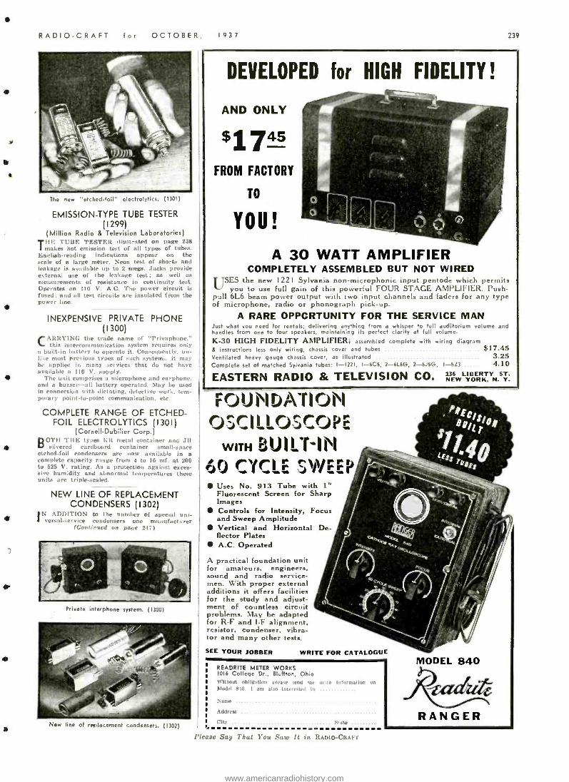
RADIO -CRAFT for OCTOBER, 1937 23?
The new "etched- foil" electrolytics. (1301)
EMISSION -TYPE TUBE TESTER (1299)
(Million Radio 8 Television Laboratories) Tllhl TUBE TESTER illustrated on page 238 makes hot emission test of all types of tubes.
Enelish- reading indications appear on the scale of a large meter. Neon test of shorts and leakage is available up to 2 megs. Jacks provide external use of the leakage test; as well as measurements of resistance in continuity test. Operates on 110 V. A.C. The power circuit is fused; and all test circuits are insulated from the
INEXPENSIVE PRIVATE PHONE (1300)
CARRYING the trade name of "Privaphone.'' this intercommunication system requires only
a built -in battery to operate it. Consequently, un- like most previous types of such systems, it may be applied in many services that do not have available a 110 V. supply.
The unit comprises a microphone and earphone, and a buzzer -all battery operated. May be used in connection with dictating, detective work, tem- porary point -to-point communication, etc.
COMPLETE RANGE OF ETCHED- FOIL ELECTROLYTICS (1301)
(Cornell -Dubilier Corp.) BOTH THE types ER metal container rut! JR
silvered cardboard container small -space etched -foil condensers are now available in a complete capacity range from 4 to 16 mf. at 200 to 525 V. rating. As a protection against exces- sive humidity and abnormal temperatures these units are triple -sealed.
NEW LINE OF REPLACEMENT CONDENSERS (1302)
IN ADDITION to the number of special uni- versal- service condensers one manufacturer
( Continued on pape 247)
Private interphone system. (1300)
New line of replacement condensers. (1302)
DEVELOPED for HIGH FIDELITY!
AND ONLY
$1745 FROM FACTORY
TO
YOU!
A 30 WATT AMPLIFIER COMPLETELY ASSEMBLED BUT NOT WIRED
USES the new 1221 Sylvania non- microphonic input pentode s.ltich permit, you to use full gain of this powerful FOUR STAGE AMPLIFIER. Push
oil 6L6 beam power output with two input channels and faders for any type of microphone, radio or phonograph pick -up.
A RARE OPPORTUNITY FOR THE SERVICE MAN Just what you need for rentals; delivering anything from a whisper to full auditorium volume and
Indies from one to four speakers, maintaining its perfect clarity at full volume.
K -30 HIGH FIDELITY AMPLIFIER; assembled complete with wiring diagram instructions less only wiring, chassis cover and tubes $17.45
'entilated heavy gauge chassis cover, as illustrated 3.25 complete set of matched Sylvania tubes: 1 -1221, 1-6CS, 2 -6L6G, 2 -6JSG, 1 -5Z3 4.10
EASTERN RADIO & TELEVISION CO. LIBERTY NS
ST. Y- roir.i
('jsril I oJC r1_ WITH BUILT-1N
rYCI SYMr Uses No. 913 Tube with 1" Fluorescent Screen for Sharp Images Controls for Intensity, Focus and Sweep Amplitude Vertical and Horizontal De- flector Plates A.C. Operated
A practical foundation unit for amateurs, engineers, sound and radio service- men. With proper external additions it offers facilities for the study and adjust- ment of countless circuit problems. May be adapted for R -F and 1 -F alignment, resistor, condenser, vibra- tor and many other tests.
SEE YOUR JOBBER WRITE FOR CATALOGUE
READRITE METER WORKS 1016 College Dr., Bluffton, Ohio R9tttout. obligation please send rue
Model 840. I am also Interested In m -.rt information on
Name ..
Address ..
City .ate
f 'lease Say That You Saw It in RADIO -CRAFT
RANGER
www.americanradiohistory.com
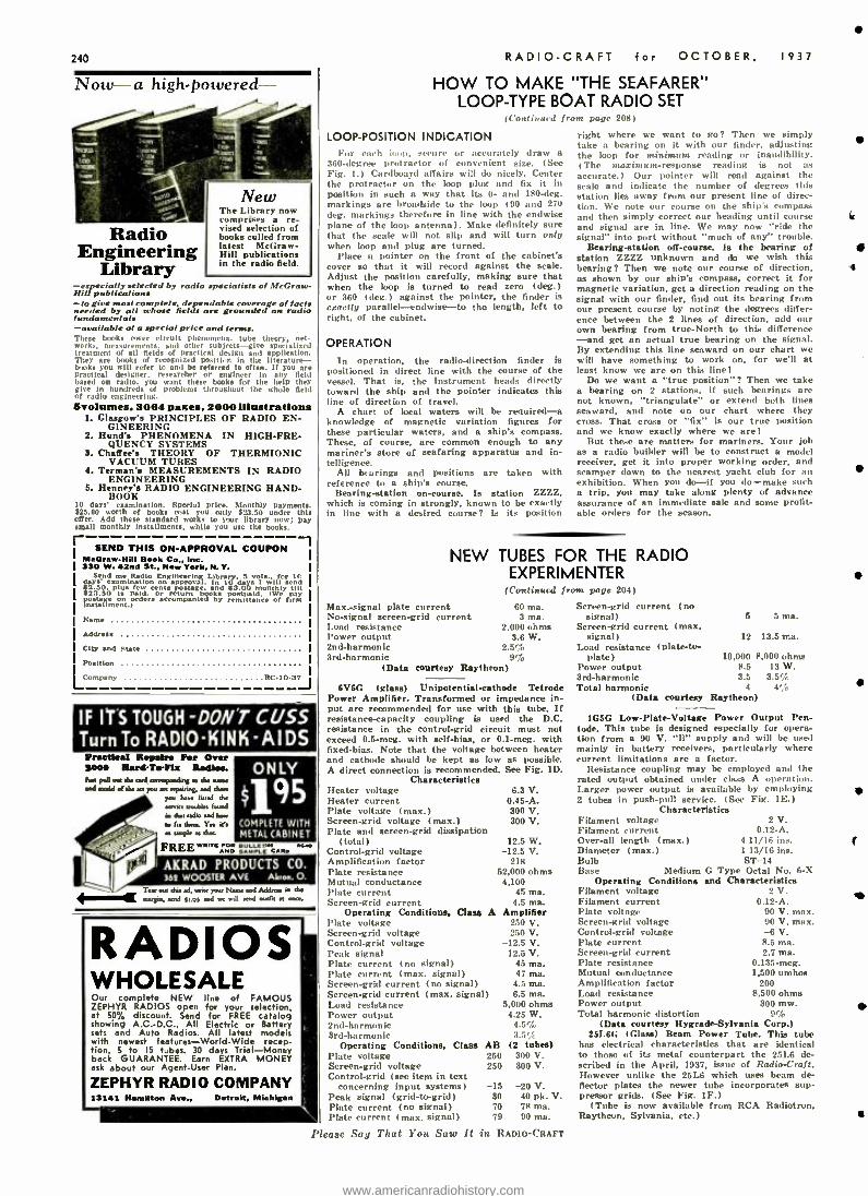
240
Now
k s,a, !
Engineering Library
-especially Hilt publications -to give needed fundamentals -available These books
mks. measurements, treatment They are btuks you practical based on give in of radio Svolames,
1. Glasgow's
2. Hund's
3. Chaffee's
4. Terman's
5. Henney's
30 days' $25.00 worth offer. Add small monthly
SEND I McGraw-NM 1 ago w,
Send days' examination I2.50.
23.50
I
ipostage nsuument.)
I Name
IAddress
[ City and
Position
Company
-a high-powered-
sneer I
sisn as
.f Radio
WI.
,,
The comprises vised books latent Hill in the
4
40
- -- New Library now
a re- selection of culled from
McGraw - publications
radio field.
selected by radio specialists of McGraw
most complete, dependable coverage of fact by all whose fields are grounded on radio
at a special price and tens. corer circuit phenomena. tube theory. net -
and other subjects-give specialized of all fields of practical design and application. books of recognized position In the llterature- will refer to and be retened to often. If you are
designer. researcher o r
engineer In any field radio. you scant these books for the help they
hundred: of problems throughout the whole field engineering.
3064 , 2000U1mtratlons PRINCIPLES OF RADIO EN-
GINEERING PHENOMENA IN HIGH -FRE-
QUENCY SYSTEMS THEORY OF THERMIONIC
VACUUM TUBES MEASUREMENTS IN RADIO
ENGINEERING RADIO ENGINEERING HAND-
BOOK examination. Special price. Monthly payments.
of books mat you only 123.50 under this these standard works to your library now; pay
installments. while you use the books.
THIS ON- APPROVAL COUPON Book Co., Ins. I
42nd St.. New York, N. Y. I me Radio Engineerin1,, Litrary, S V Isµ for I
on approval. In w days i will d pion few cents postage, d 83.00 onthly till Is ppsld. o return hoods paid. owe pay o rders accompanied
re by remittance of teat
1
I
Brat. I
RC10 -37
IF ITS TOUGH -DON'T CUSS Turn To RADIO-KINK -AIDS Praetial Saa4 ton sad andd
IT..g
Repairs Per Over Hard -T.41z Radios.
ar d,. as g. d. name
d do ar yco ." ">dog in vat doe
strike [roubles h.,,d in ,ha ,d.wain. no 1.. dam. Y., :r. . t FREE"'"::: ó
O N LY
9 5 COMPLETE WITH METAL :r,n
s caws
I AKRAD PRODUCTS CO. 362 WOOSTER AVE Akron. O.
out d.n .d, ,rue Nu,.. and Warn. ,tow . -.,g.,,, .a sys and ...di ,.oat west at
RADIOS WHOLESALE Our complete NEW line of FAMOUS ZEPHYR RADIOS open for your selection, at 50/ discount. Send for FREE catalog showing A.C.-D.C., All Electric or Battery sets and Auto Radios. All latest modeis with newest features -World -Wide recep- tion, 5 to IS tubes. 30 days Trial -Money back GUARANTEE. Earn EXTRA MONEY ask about our Agent -User Plan.
ZEPHYR RADIO COMPANY 13141 Hamilton Av.., Detroit, Michigan
RADIO -CRAFT for OCTOBER, 1937
HOW TO MAKE "THE SEAFARER" LOOP -TYPE BOAT RADIO SET
(Continued from Page 208)
LOOP -POSITION INDICATION For each Ioop, eru re or accurately draw a
360 -degree protractor of convenient size. (See Fig. 1.) Cardboard affairs will do nicely. Center the protractor on the loop plug and fix it in position in such a way that its 0- and 180 -deg. markings are broadside to the loop (90 and 270 deg. markings therefore in line with the endwise plane of the loop antenna). Make definitely sure that the scale will not slip and will turn only when loop and plug are turned.
Place a pointer on the front of the cabinet's cover so that it will record against the scale. Adjust the position carefully, making eure that when the loop is turned to read zero (deg.) or 360 (deg.) against the pointer, the finder is exactly parallel- endwise -to the length, left to right, of the cabinet.
OPERATION
In opertnion, the radio -direction finder is positioned in direct line with the course of the vessel. That is, the instrument heads directly toward the ship and the pointer indicates this line of direction of travel.
A chart of local waters will be renuired -a knowledge of magnetic variation figures for these particular waters, and a ship's compass. These, of course, are common enough to any mariner's store of seafaring apparatus and in- telligence.
All bearings and positions are taken with reference to a ship's course.
Bearing- station on- course. Is station ZZZZ, which is coming in strongly, known to be exactly in line with a desired course? position
NEW
Max. -signal plate current No- signal screen -grid current Load resistance Power output 2nd- harmonic 3rd- harmonic
(Data courtesy
right where we want to go? Then we simply take a bearing on it with our finder, adjusting the loop for minimum reading or inaudibility. (The maximum- response reading is not as accurate.) Our pointer will read against the settle and indicate the number of degrees this station lies away from our present line of direc- tion. We note our course on the ship's compass and then simply correct our heading until course and signal are in line. We may now "ride the signal" into port without "much of any" trouble.
Bearing- station off- course. Is the bearing of station ZZZZ unknown and do we wish this bearing? Then we note our course of direction, as shown by our ship's compass, correct it for magnetic variation, get a direction reading on the signal with our finder, find out its bearing from our present course by noting the degrees differ- ence between the 2 lines of direction, add our own bearing from true -North to this difference -and get an actual true bearing on the signal. By extending this line seaward on our chart we will have something to work on, for we'll at least know we are on this line!
Do we want a "true position "? Then we take a bearing on 2 stations, if such bearings are not known, "triangulate" or extend both lines seaward, and note on our chart where they cross. That crass or "fix" is our true position and we know exactly where we are!
But these are matters for mariners. Your job as a radio builder will be to construct a model receiver, get it into proper working order, and scamper down to the nearest yacht club for an exhibition. When you do-if you do -make such a trip, you may take along plenty of advance assurance of an immediate sale and some profit- able orders for the season.
TUBES FOR THE RADIO EXPERIMENTER
( Continatd from page 204)
60 ma. 3 ma.
2,000 ohms 3.6 W.
2.5% 9 ó
Raytheon)
6V6G (glass) Unipotential- cathode Tetrode Power Amplifier. Transformed or impedance in- put are recommended for use with this tube. If resistance- capacity coupling is used the D.C. resistance in the control -grid circuit must not exceed 0.5 -meg. with self -bias. or 0.1 -meg. with fixed -bias. Note that the voltage between heater and cathode should be kept as low as possible. A direct connection is recommended. See Fig. ID.
Characteristics Heater voltage 6.3 V. heater current 0.45 -A. Plate voltage (max.) 300 V. Screen -grid voltage (max.) 300 V. Plate and screen -grid dissipation
(total) 12.5 W. Control -grid voltage -12.5 V. Amplification factor 218 )'late resistance 52,000 ohms Mutual conductance 4,100 l'Inte current 45 ma. Screen -grid current 4.5 ma.
Operating Conditions, Class A Amplifier Plate voltage 2.0 V. Screen -grid voltage 250 V. Control -grid voltage -12.5 V. Peak signal 12.5 V. Plate current (no signal) 45 ma. Plate current (max. signal) 47 ma. Screen -grid current (no signal) 4.5 ma. Screen -grid current (max. signal) 6.5 ma. Load resistance 5,000 ohms Power output 4.25 W. 2nd -harmonic 4.5% 3rd -harmonic
Operating Conditions, Class AB (2 tubes) Plate voltage 250 300 V. Screen -grid voltage 250 300 V. Control -grid (see item in text
concerning input systems) -15 Peak signal (grid -to-grid) 30 Plate current (no signal) 70 I'late current (max. signal) 79
-20 V. 40 pk. V. 78 ma. 90 ma.
Please Say That You Satu It in RADIO -CRAFT
Screen -grid current (no signal)
Screen -grid current (max. signal)
Load resistance (plate -to- plate)
Power output 3rd -harmonic Total harmonic
(Data courtesy
5 5 ma.
12 13.5 ma.
10,000 8,000 ohms 8.5 13 W. 3.5 3.5'/
4 4!: Raytheon)
1G5G Low -Plate- Voltage Power Output Pen- tode. This tube is designed especially for opera- tion from a 90 V. "B" supply and will be used mainly in battery receivers, particularly where current limitations are a factor.
Resistance coupling may be employes) and the rated output obtained under class A operation. Larger power output is available by employing 2 tubes in push -pull service. (See Fig. 3E.)
Characteristics Filament voltage 2 V. Filament current 0.12 -A. Over -all length (max.) 4 11 /16 ins. Diameter (max.) 113/16 ins. Bulb ST -14 Base Medium G Type Octal No. 6 -X
Operating Conditions and Characteristics Filament voltage Filament current Plate voltage Screen -grid voltage Control -grid voltage Plate current Screen -grid current Plate resistance Mutual conductance Amplification factor Load resistance Power output Total harmonic distortion
2 V. 0.12 -A.
90 V. max. 90 V. max. -6 V. 8.5 ma. 2.7 ma.
0.135 -meg. 1,500 umhos
200 8,500 ohms
300 mw. 9 ó
(Data courtesy Hygrade- Sylvania Corp.) 25L6G (Glass) Beam Power Tube. This tube
has electrical characteristics that are identical to those of its metal counterpart the 25L6 de- scribed in the April, 1937, issue of Radio -Craft. However unlike the 25L6 which uses beam de- flector plates the newer tube incorporates sup- pressor grids. (See Fig. 1F.)
(Tube is now available from RCA Radiotron, Raytheon, Sylvania, etc.)
4
f
ID
www.americanradiohistory.com
w
RADIO -CRAFT for OCTOBE R, 1937
CRYSTAL ,HEAD PHONES
SOUND CELL MICROPHONES
Information on request THE BRUSH DEVELOPMENT CO. 3312 PERKINS AVE CLEVELAND, OHIO
i
RADIO COURSES RADIO OPERATING: Prepare for Gov't License Exam. RADIO SERVICING: including Short WaveAMATEUR CODE
ELECTRONICS TELEVISION Day and Evening Classes- Dookiet Upon Requt I
New York YMCA School W. 64th Street. New York C,ty
BUILD IT YOURSELF You Can build this Trailer with ordinary tools easily frroto our Step-by-step constructional 'heats and large Shed blueprints. ripest designed lr.ilee in existence. sleeps 4. Toilet. Simms'. Etto-
Ae r6?...t the cost by building it yourself. teed 2Sc for pisa. t. pweoaone end dead..
THE PLAN SHOP. 910 Palmolive Bldg. Chicago. II.
MODERNIZE YOUR OBSOLETE TUBE CHECKER OR SET
ANALYZER with "PRECISION" Write for details. Mention make and model
number of your old instrument.
PRECISION APPARATUS CORP. 821 EAST NEW YORK AVE. BROOKLYN. N. V.
RRDI05..5RVE;o50% DEAL DIRECT...FACTORY PRICES! Man odels to se- 3 !vet( rom:
u AC- DC :AII- W ave;
nflair model.: automae inrear. radine: Farmeeta
that operate like city adios! end tcard for NEW
limeade Catalog FREE. 9o. ^ nAY TRIAL pln nd
'nt-oser propoeitioni
OE. T RADIO CO. MICHIGAN
PATENTS -TRADE MARKS AU cases submitted given personal attention by
members of the tiro. Form "Evidence of Conception" and
instructions "How to Estblish Your RiOAts" -Free
LANCASTER. ALLWINE & ROMMEL PATENT LAW OFFICES
436 Rowan Bldg. Washington, D. C.
$500,000 GENUINE MAJESTIC- GRIGSBY GRUNOW REFRIGERATOR B RADIO PARTS. 2000 REFRIG. ERATOR UNITS
UNITS GUARAN-
TEED 18 MONTHS. SEND FOR PRICE LIST.
G B G GENUINE MAJESTIC RE- FRIGERATOR 8 RADIO PARTS SERVICE
5801 W. DICKENS AVE. CHICAGO, ILL.
5 TUBE SUPER KIT 56 K.C. 15 to SO Meters 200 to SSO Metes Kit vi ,.i.1. of: I. F. Trans.. Var. Condenser. Chassie Pan. toils, Sn,-krls. Padding. Filter and Ity Pass Condensers. its. i$ors. l'mver Trans. and Schematic Drawing. All above parts with G'e.' speaker $5.95 All Anne patio with 8° speaker . 6.95
25 '. Depo.is Required With Order WRITE FOR OUR NEW R PAGE FLYER
ARROW SALES COMPANY Dent. 5 631 WASHINGTON BLVD.. CHICAGO. ILLINOIS
"LEARN -BY- EXPERIMENTING" BEGINNERS' PRACTICAL
RADIO COURSE (Continued from page 233)
LIST OF PARTS FOR EXPERIMENT NO. I
One general purpose, audio microphone trans- former, T;
One adjustable condenser (optional). 0.0003- to 0.001 -mf. (equivalent to 300 to 1.000 mmf.) ;
One rheostat, 20 ohms, R; One 4 -prong socket, with screw
type 30 tube: One knob and dial- plate; Five binding posts ;
One type 30 tube; or, type OlA tube may be used, with rheostat advanced to full, since this tube requires a greater operating current;
Three drycells, or one 4'_ V. "C" battery; One pair of standard headphones, 2,000 ohms
resistance, Ph.: One key. may be home -made, as shown, or push-
button. K. 'Names of manufacturers will be supplied upon
receipt of a stamped and self -addressed envelope.
terminals for
The author of this course has been identified with the teaching of radio for many years in both private and public schools, and at present is an Instructor in Radio in a New York City High School. His experience qualifies him ad- mirably for presenting the technical material of radio from the learner's viewpoint.
ANSWERS TO PROBLEMS ON EXPERIMENT No. I
(Sec page 233)
(1) Filament current becomes gn'ater. (2) Tone becomes lower in pitch indicating a
Blower or lower frequency. (3) Pitch becomes looser indicating slower or
lower frequency. (4) Breaking the plate circuit. (5) The amount of capacity in the grid circuit.
BUILD THIS "INTERMITTENT OPEN"
CONDENSER TESTER (Continued from page 225)
will -insulated test prods and keep safely away from the R.F. output of this "breakdown -test oscillator" in order to avoid high -frequency burns.
Coil L consists of 76 turns of No. 24 enam. wire wound on a form (preferably, air -core) IV,. ins. in dia, Coils LI and L2 each consist of 50 turns of No. 14 enam. wire wound on a form 1% ins. in dia.
The following List of Parts is suggested to builders who may want to try out this idea in a lab. set -up. Substitutions may be made by the experienced radio man as necessary to suit in- dividual convenience.
LIST OF PARTS One Standard Transformer Corp. power trans- former, 650 V., 150 ma. sec. and a 2.5 V. sec.,
T; One Standard Transformer Corp. filter choke,
200 ma., Ch.]; One Hammarlund R.F. choke, 150 ma., Ch.: One Hammarlund variable condenser, 350 mmf.,
CV; Two Tung -Sol type 45 tubes, Vl. V2; One Tung -Sol type HO tube, V3; Two Sprague condensers, No. TX- 24 -70, 70 mmf.,
1,500 V., C: One I.R.C. resistor, 25,000 ohms, 5 W. (no less),
R; One Sprague condenser, No. TC -25, 0.005 -mf.,
400 V., Cl; One Sprague condenser, No. TR -11, 0.01 -mf..
800 V., C2; Two Sprague condensers, No. OT -21, 2 mf., 800
V., C3; One R.F. coil unit (see text for construction
data) L, LI, L2; One S.P.S.T. toggle switch, X; One bulb (and socket), 2.5 V. filament, V.: Three 4 -prong sockets.
This article has been prepared from data sup- plied by courtesy of Sprague Products Co.
Please Say That You Saw It in RADIO -CRAFT
BEFORE
YOU
241
LL
t'y How would you like to have a good stock of nationally adver- tised radio tubes on your shelves - without paying a nickel until they're sold?
That's how the Tung -Sol Con- signment Plan works for radio dealers who can qualify. You don't pay for the tubes until you've collected your cost and profit. That's worth looking into -to see if you are eligible for this unique plan.
More than 8,000 dealers have qualified -and are going places in the tube business.
Full profit -no investment -no dead numbers to write off at a loss. Easy to sell, because your trade knows that Tung -Sol means top flight tube efficiency.
l {ranChIS¢
se
1S
1 Tung So limited
sä11 available
to a
urn b¢" o) d¢aleta who can
a
Ai 10 ualilY
Wltolesal¢r
01 YOU" neatest
TUNG-SOL CJtfnz- f lvw Radio 04.,13-ea.
TUNG -SOL LAMP WORKS. INC. Dept. F Radio Tube Division SALES OFFICES: Atlanta, Boston. Chicago, Charlotte, Dallas, Detroit. Kansas City, Los Angeles, New York.
General Office, Newark, N. I.
www.americanradiohistory.com
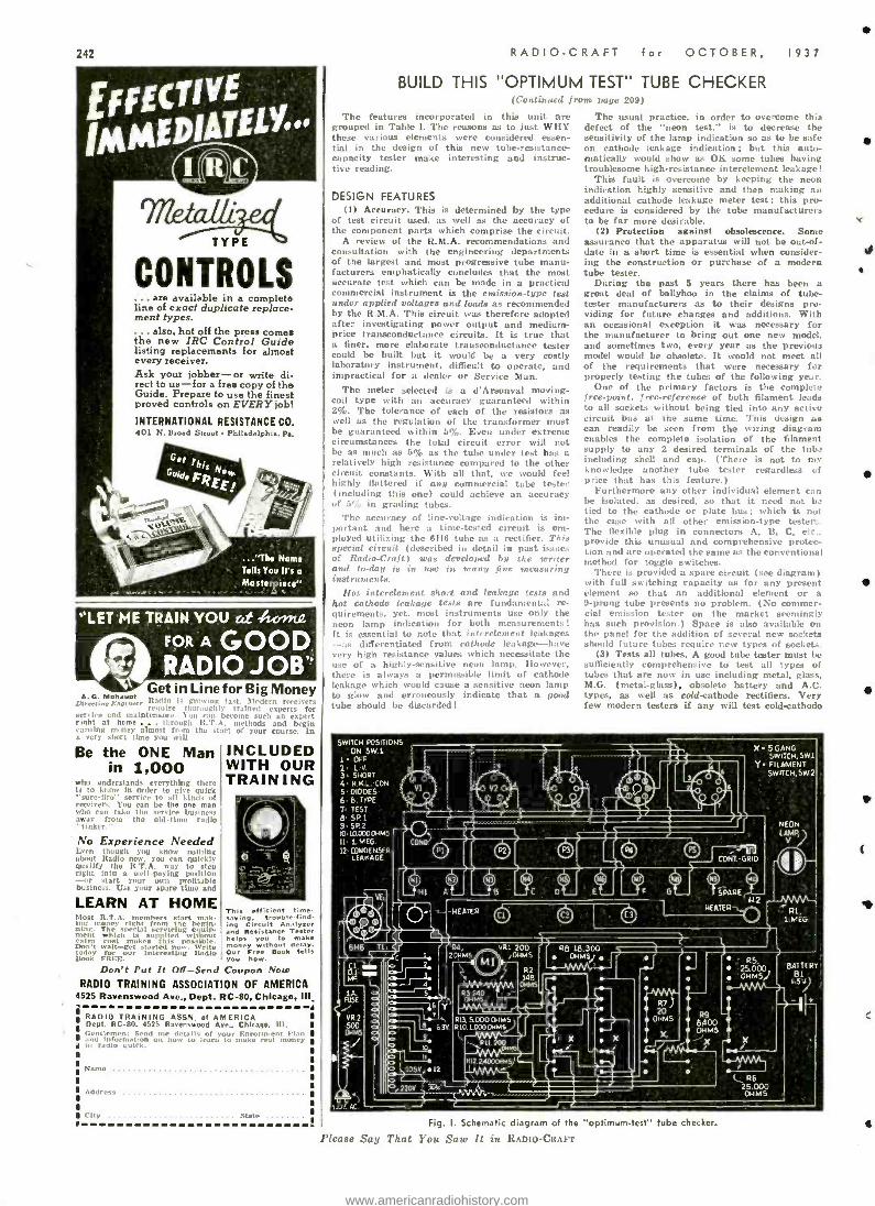
242
TYPE
CONTROLS .. are available in a complete
line of exact duplicate replace- ment types.
. also, hot off the press comes the new IRC Control Guide listing replacements for almost every receiver. Ask your jobber -or write di- rect to us -for a free copy of the Guide. Prepare to use the finest proved controls on EVERY job!
INTERNATIONAL RESISTANCE CO. 401 N. Broad Street Philadelphia, Pa.
... "The Name
Tells You Its a
Masterpiece"
'LET ME TRAIN YOU sit Avrng. FORA GOOD, RADIO JOB" 1iy Get in Line for Big Money
A. G. Mohaupt Ife :. I.t, [ )Iilrrn T Uirvrlinu F.nwioser naps ire IIIp1'.uAlly' trained experts fer
sennAre and mainten e. Y,.:t I be.nne such an expert rinht at home - .
_ It T ('
t 11.. 1- .ta i.::In
Be the ONE Man INCLUDED in 1,000 WITH OUR
who understands e en'w:ng IlL TRAIN I N G ill to know in order lo Ore "sure -fire' service to all kind- receivers. You can be the one man who can take coo servire business away Burn the old -time radio "tinker." ' No Experience Needed Even though you know nothing about Radio you can quickly qualify the R.T.A. way to step right into a wellpaying position
m start your own profitable business. Use your aparo time and
LEARN AT HOME Most S.T.A. sera tart mak- ing, money right front the begin - mThe special servicing equip- ment which is supplied with t extra cost makes this possible. Don't wait -get s arted n. Write today for our interesting Dada,' Titer.
This efficient time -
insinCircú t u
ize- Analyzer
and Resistance Tester
money you te make
e without delay Free Free Book tells
you how. Don't Put It Off-Send Coupon Now
RADIO TRAINING ASSOCIAT ON OF AMERICA 525 Ravenswood Ave., Dept. RC -80, Chicago, III
RADIO TRAINING ASSN. of AMERICA Dept. RC -80, 4525 Ravenswood Ave., Chleage. III. Gentlemen: Send me details of your Enrollment elan ami informa on how tu learn to make real mulle» to ratto quirk
Name
Address
('Hy State
RADIO -CRAFT for OCTOBER, 1937
BUILD THIS "OPTIMUM TEST" TUBE CHECKER (Co sat iaHUl Irorn page 209)
The features incorporated in this unit are r.rouped in Table 1. The reasons as to just WHY these various elements were considered essen- tial in the design of this new tube-resistance- capacity tester make interesting and instruc- tive reading.
DESIGN FEATURES (I) Accuracy. This is determined by the type
of test circuit used, as well as the accuracy of the component parts which comprise the circuit.
A review of the R.M.A. recommendations and consultation with the engineering departments of the largest and most progressive tube manu- facturers emphatically concludes that the most accurate test which can be made in a practical commercial instrument is the emission -type text under applied voltages and loads as recommended by the A.M.A. This circuit was therefore adopted after investigating power output and medium - price transconductanee circuits. It is true that a finer, more elaborate transconductanee tinter could be built but it would be a very costly laboratory instrument. difficult to operate, and impractical for a dealer or Service Man.
The meter selected is a d'Arsonval moving - coil type with an accuracy guaranteed within 2 %. The tolerance of each of the resistors as well as the regulation of the transformer must be guaranteed within 5%. Even under extreme circumstances the total circuit error will not be as much as 5% as the tube under test has a relatively high resistance compared to the other circuit constants. With all that, we would feel highly flattered if any commercial tube tester (including this one) could achieve an accuracy of 5,í in grading tubes.
The aces racy of line- voltage indication is im- portant and here a time -tested circuit is em- ployed utilizing the 6H6 tube as a rectifier. This special circuit (described in detail in past issues of Radio -Craft) was developed by the xeriter and to -day is in Lase in many fine measuring instruments.
Hot interelement short and leakage tests and hot cathode leakage tests are fundamental re- quirements, yet, most instruments use only the neon lump indication for both measurements! It is essential to note that interelement leakages -as differentiated from cathode leakage-have very high resistance values which necessitate the use of a highly -sensitive neon lamp. However, there is always s a permissible limit of cathode leakage which would cause a sensitive neon bump W glow and erroneously indicate that a good tube should be discarded!
The usual practice, in order to overcome this defect of the "neon test," is to decrease the sensitivity of the lamp indication so as to be safe on cathode leakage indication; but this auto- matically would show as OK some tubes having troublesome high -resistance interelement leakage!
This fault is overcome by keeping the neon indication highly sensitive and then making an additional cathode leakage meter test; this pro- cedure is considered by the tube manufacturers to be far more desirable.
(2) Protection against obsolescence. Some assurance that the apparatus will not be out -of- date in a short time is essential when consider- ing the construction or purchase of a modern tube tester.
During the past 5 years there has been a great deal of ballyhoo in the claims of tube - tester manufacturers as to their designs pro- viding for future changes and additions. With an occasional exception it was necessary for the manufacturer to bring out one new model. and sometimes two. every year as the previous model would be obsolete. It would not meet all of the requirements that were necessary for properly testing the tubes of the following year.
One of the primary factors is the complete free- point, free- reference of both filament leads to all sockets without being tied into any active circuit bus at the same time. This design as can readily be seen from the wiring diagram enables the complete isolation of the filament supply to any 2 desired terminals of the tubs including shell and cap. (There is not to nu' knowledge another tube tester regardless cf price that has this feature.)
Furthermore any other individual element can be isolated, as desired. so that it need not bs tied to the cathode or plate bus; which is not the case with all other emission -type tester... The flexible plug in connectors A. Is, C, etc.. provide this unusual and comprehensive protec- tion and are operated the same as the conventional method for toggle switches.
There is provided a spare circuit (see diagram) with full switching capacity as for any present element so that an additional element or a 0 -prong tube presents no problem. (No commer- chd emission tester on the market seemingly has such provision.) Space is also available on the panel for the addition of several new sockets should future tubes require new types of sockets.
(3) Tests all tubes. A good tube tester must be sufficiently comprehensive to test all types of tubes that are now in use including metal, glass, M.G. (metal -glass), obsolete battery and A.C. types, as well as cold- cathode rectifiers. Very few modern testers if any will test cold -cathode
SWITCH POSITIONS ON SW.1
1. OFF 2 L-V
3 SHORT 4 H NL -EON
5 DIDOES 6 b.TYPE 7 1E51 B'SPI 9.SP2 lo Ia0000e14s 11 1 MEG
12 CONnENSER LEAKAGE
VU
)
2
1
o I- MF
is FUSE
VR 2
QMS
f4 110. AC
HEATER Ci
R4, 20HMS
X. 5 GANG SWITCH, SW I
Y FILAMENT SWITCH, SW 2
uu CONT-GRID
ra_
EATERz_ H2
H
R8 18,300 OHMS)
5
6 /' Loy 63V
9
C
10575.12
RI7. 5.000 OHMS R 10,1,0000HMS,
X
R7 ) 20
OHMS R9
8400 X
t OHMS
°, 220
R6 25.000 OHMS
25.000 ,
OHMS/
NEON LAMP, / s
v
Rl, 1.MEG
BATTERY 131
Fig. I. Schematic diagram of the "optimum- test" tube checker.
Please Say That You Saw It in RADIO -CRAFT
www.americanradiohistory.com
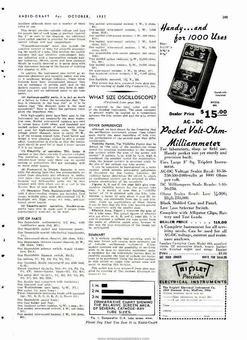
RADIO -CRAFT for OCTOBER,
rectifiers although there are a number of these tubes in use.
This design provides suitable voltage and load for proper test of such tubes at position "special No. 1" as seen in the diagram. An additional spare switch position is provided for some future special voltage and load requirement.
"Comprehensiveness" must also include the complete number of tests fur properly determin- ing the worth of a tube. This involves the quality emission test and sensitive inter -element leak- age indication with a less- sensitive cathode leak- age indication. Shorts, opens and loose elements should be readily detected as is easily done with this instrument because of the feature of isolating any element at will.
In addition the instrument also serves as an accurate ohmmeter and capacity meter, and also as a condenser leakage indicator. The extra features have been incorporated because they are so necessary in service work and on the dealer's counter, and involve very little in addi- tional cost and no additional space to the tube tester.
(4) Optimum -quality parts. It is just as much of a fallacy to follow the assumption that "the best Ls cheapest in the long run" as it is to believe that "the cheapest price is the most economical." Here is where the optimum value plays the important role.
Only high -quality parts have been used in this instrument but not necessarily the most expen- sive ones. Molded wire -wound resistors are used in values below 2.5110 ohms, and insulated and molded carbon resistors of ample watts rating are used for high -resistance units. The line - voltage power rheostat, rated to carry 25 W.. is of the vitreous enamel type. Panel layout and design is very pleasing; etched to give a 2 -color effect. Construction is sturdy so that the instru- ment should be good for at least 5 years' service if it Ls not abused.
(5) Simplicity of operation. This factor is realized in that there are only 2 selector switches. The operation is similar to the conventional emission -type tester only there are no special sockets or precautions that are necessary with so many other testers.
(6) Economical in Design. Economy is veri- tably the shining light that has automatically re- sulted from simplicity and efficiency in design. Just think -this unusual tester with its splendid features and high- quality parts can be con- structed with little effort and at a cost to the Service Man of only about $18.
(7) Ohmmeter Tests. Resistance -test facilities, with 2 direct -reading ranges, are included. Low range: 0- 10,000 ohms, with self- contained 1% V. flashlight cell. High range, 0 -1 meg., self -con- tained power supply.
(8) Capacity -meter operation. Condenser -ca- pacity tests may be made over 2 ranges from approximately 0.001 -mf. to 10 mmf.
LIST OF PARTS One Dependable milliammeter, 0 -5 ma.. with
combination scale dial, Ml; One Dependable etched and fabricated panel; One Dependable special tube -testing transformer,
Ti; One wire -wound shunt rheostat, 200 ohms, VRI; One Dependable vitreous enamel rheostat, 25 W.,
500 ohms, VR2; One Dependable selector switch. 6 -pole 12 -posi-
tion. Sw.l ;
One Dependable filament switch, Sw.2; Six sockets, VI, V2, V3. V4, V5, V6; One insulated, double control -grid cap with lead,
C.-G.; Eleven insulated tip -jacks, Red -P1, P2, P3, P4,
P5, CP, Heater -Heater, Black -K1, K2, K3; Ten metal shell tip -jacks, NI, N2, N3, N4, N5,
NG, N7, N8, N9, N10; Ten flexible lead connectors with insulation; One line -cord and plug; One Westinghouse neon lamp, 1/4-W., NL; One socket for neon lamp; Three Dependable indicating knobs with insulated
tips, Ill, A. B. C, D, E, F, G, Spare 112; One Dependable round knob; One fuse holder and fuse; One insulated carbon resistor, % -W., I meg., RI; One molded wire -wound resistor. 1 W., 148 ohms,
R2; One molded wire -wound resistor, 1 W, 240 ohms,
R3;
1937
One molded wire -wound resistor, 1 W., 2 ohms, R4;
One molded wire -wound resistor, 1 W., 1,000 ohms, RIO;
One molded wire -wound resistor. 1 W., 200 ohms, Ru;
One molded wire -wound resistor, 1 W., 2,400 ohms, R12;
One molded wire -wound resistor, 1 W., 5,000 ohms, R13;
One Dependable wire-wound rheostat, 200 ohms, VR1;
Two molded carbon resistors, 1/4-W., 25,000 ohms, R5, R6;
One molded carbon resistor, 1/4-W., 18,500 ohms, R8;
On wire -wound resistor, 1 W., 20 ohms, R7; One insulated carbon resistor, 1 W., 8,400 ohms,
RO; One flashlight monocell, 1% V., Bi.
This article has been prepared from date sup- plied by courtesy of Radio City Products Co., Inc.
WHAT SIZE OSCILLOSCOPE? (Continued from pout 205)
as compared to the total value and cost of the finished instrument. The same comment in general might be applied to a comparison between the 2 -in. screen size and the 3 -in. screen size.
OTHER DIFFERENCES Although we have shown by the foregoing that
the oscilloscope instrument proper (less tubes) costs nearly the same regardless of tube size, the performance of the several sizes may differ considerably.
Visibility Factor. The Visibility Factor may be defined as "the ratio of the smallest -size image useful for practical examination to the largest - size pattern which the area of the screen will permit." A pattern 1/4-in. wide by 1 -in. high is considered the smallest useful for examination. while the largest pattern is governed solely by the size of the cathode ray tube screen.
It can be compared to band -spread on a radio receiver which permits micrometer adjustment of frequency for fine tuning. Likewise, the visibility factor determines the extent to which an oscilloscope pattern can be enlarged to allow precise examination of its waveform.
Figures A, B and C (on page 205) give com- parative visibility factors for the several tube sizes. It is worthy of note that a "visibility factor" of 75 is obtained with the 3 -in. tube, whereas a factor of only about 8 and 23, re- spectively, are obtainable from the 1- and 2 -in. tubes. From an examination of these figures it can be seen that the 3 -in. tube benefits greatly by comparison with the smaller sizes.
Effective Area. Figure 1 compares the area of the 3 tube sizes. The actual figures of effective area are given, at A, B, and C, page 205. It is well to consider a cathode ray tube screen from the angle of effective usable area. because in this way the true proportions of the image can be anticipated.
SUMMARY It is entirely passible that servicing work in
the near future will require more extensive use of full -size oscilloscope equipment. Ultra- modern receivers and the possibility of servicing work to be done on television equipment make it necessary for the wide -awake Service Man to carefully consider the type of cathode ray equip- ment to be purchased. Using the method outlined in this article to judge tube screen sizes will assist in making this decision.
This article has been prepared from data sup- plied by courtesy of The Jackson Electrical In- strument Co.
1 IN.
2 IN
31N.
COMPARATIVE CHART SHOWING THE RELATIVE SCREEN AREA. OF SEVERAL CATHODE-RAY
TUBE SIZES. F; q
Please
uncir,.ssand bot /000 usas
243
Ccmpl tt
lmn:n.d
MODEL
Dealer Price $ 1 5.O°
L 1AC '/- (/j POf/lQC I OLL-V hm-
AbLia//iin G tIQ L For laboratory, shop or field use.
Handy pocket size yet sturdy and precision built.
Uses Large 3" Sq. Triplett Instru- ment.
AC -DC Voltage Scales Read: 10-50- 250 -500 -1000 -volts at 1000 Ohms per volt.
DC Milliampere Scale Reads: 1 -10- 50 -250.
Ohms Scales Read: Low % -300; High 250,000.
Black Molded Case and Panel. Low Loss Selector Switch. Complete with Alligator Clips, Bat -
ti'ry and Test Leads. DEALER PRICE $15.00 A Complete Instrument for all serv-
icing needs. Can be used for all AC -DC voltage, current and resist- ance analyses.
Leather Carrying Case, Model 669, supplied extra. Of attractive black, heavy leather with finished edges and strap. Dealer Price $3 00 SEE YOUR JOBBER WAITE FOR CATALOG
te
a ;LEr, paecíai47%i
LELECTRICAL INSTRUMENTS.
I. Comparative C. -R. tube screen areas.
Say That You Saw It in RAMO -CRAFT
The Triplett Electrical Instrument Co. 1610 Harmon Ave., Bluffton, Ohio Without obligation please send me
--More Information nn Model GM1t. --I am also hrttrtgtd in
Name
Address
CRY late a
www.americanradiohistory.com
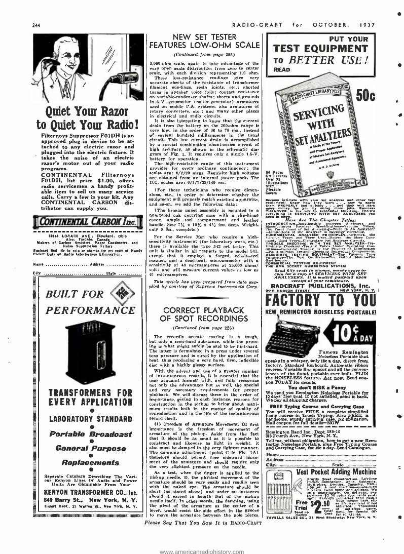
244
Quiet Your Razor to Quiet Your Radio!
Filternoys Suppressor FO1DH is an approved plug -in device to be at- tached to any electric razor and plugged into the electric fixture. It takes the noise of an electric razor's motor out of your radio programs. CONTINENTAL Filternoys FO1DH, list price $1.00, offers radio servicemen a handy profit- able item to sell on many service calls. Carry a few in your kit. Any CONTINENTAL CARBON dis- tributor can supply you.
IItÁ1 RIXEILIL CARBON Inc.11
13914 LORAIN AVE.. Cleveland. Ohio Also. Toronto. Canada
Makers of Carbon Resistors. Paper Condensers, and Noise Suppression Filters
Enclosed find 10c In coin or stamps for my copy of Handy Pocket Data on Radio Interference Elimination.
Name Address
City State
BUILT FOR
PERFORMANCE
TRANSFORMERS FOR EVERY APPLICATION
LABORATORY STANDARD
Portable Broadcast
General Purpose
Rep lacements Separate Catalogs Describing The Vari- ous Kenyon Lines Of Audio and Power
Units Are Obtainable From Your
KENYON TRANSFORMER CO., Inc. 840 Barry St., New York, N. Y. Export Dept.. 25 Warren St.. New York. N. V.
II11111111II111111I I I II III1 1 1 1 1 1 1IIII I111111111I IIIIIIIIIIIIIIIIIIII III1111111111I111111111I II I III
RADIO -CRAFT
NEW SET TESTER FEATURES LOW -OHM SCALE
(Continued from page 205)
2,000-ohm scale, again to take advantage of the very open scale distribution from zero to center scale, with each division representing 1.0 ohm.
These low- resistance readings give very accurate checks of the resistance of transformer filament windings, resin joints, etc.; shorted turns in speaker voice coils ; contact resistance on variable- condenser shafts ; shorts and grounds in 6 -V. genemotor (motor- generator) armatures used on mobile P.A. systems, also armatures of rotary converters, etc.; and many other places in electrical and radio circuits.
It is also interesting to know that the current drain from the battery on the 200-ohm range is very low, in the order of 60 to 70 ma., instead of several hundred milliamperes in the usual circuit. This low current drain is accomplished by a special combination shunt -series circuit of high accuracy, as shown in the schematic dia- gram of Fig. 1. It requires only a single 1.5 -V. battery for operation.
The high -resistance range of this instrument provides for every ordinary contingency ; the scales are: 0/2/20 mega. Requisite high voltages are obtained front an internal power pack. The D.C. scales are: 0/1/7/35/140 ma.
(For those technicians who require dimen- sions, etc., in order to determine whether the
equipment will properly match existing apparatus, and soon, we add the following data:
(The bronze panel assembly is mounted in a quartered oak carrying case with a slip -hinge cover. ample tool compartment and leather handle. Size 714 x 10!(: x 4pÿ ins. deep. Weight. only 9 lbs., complete.)
For the Service Men who require a high - sensitivity instrument (for laboratory work, etc.) there is available the type 542 aet tester. This unit is similar in all respects to the model 541, except that it employs a forged, cobalt -steel magnet, and a dead -beat, microammeter with a sensitivity of 40 microamperes at 25,000 ohms/ volt; and will measure current values as low as 40 microamperes.
This article has been prepared from data sup- plied by Cmote:ay of Supreme Instruments Corp.
CORRECT PLAYBACK OF SPOT RECORDINGS
(Continued from page 226)
The record's acetate coating is a tough, but only a semi -hard substance, while the press- ing is what might safely be said to be flint -hard. The latter is formulated in a press under several tons pressure and is cured by the application of heat, thus producing a very hard, firm, inflexible disc with a highly glossy surface.
With the advent and use of a greater number of instantaneous records, it is essential that the user acquaint himself with, and fully recognize not only the advantages but as well, the special and very necessary requirements for proper playback. We will discuss these in the order of importance. giving in each instance, masons for construction in the pickup to bring about maxi- mum results both in the matter of quality of reproduction and in the life of the instantaneous record itself.
(1) Freedom of Armature Movement. Of first importance is the freedom of movement of armature of the pickup. Aside from the fact that it should be as small as it is possible to construct and likewise as light in weight, it also must be damped in the very lightest manner. The damping adjustment (point C in Fig. 1A) therefore should permit free sideward move- ment of the armature and should require only the very slightest pressure on the needle.
As a test. when the finger is applied to the pickup needle. D, the physical movement of the armature should be very easily and readily seen with the naked eye. The armature should be abort (as stated above) and under no instances should it exceed in length that of the pickup needle itself. In other words, the damping, using the pivot of the armature as the center of a lever, would resist the side effort in the groove to move the armature between the pole pieces.
Please Say That You Saw It in RADIO-CRAFT
for OCTOBER, 1937
PUT YOUR
TEST EQUIPMENT TO BETTER USE ! READ
64 Pages 6 a 9 Inches Over 75 Illustrations SON. Flexible Covers
Become intimate with your set analyzer and other test equipment! Know how they work . how to apply them PROPERLY and quckidoing . . and theey. will
earn TURNOVER
money for you key to salol
more servicing. There's
ever things in SERVICING WITH SET ANALYZERS you
Here Are The Chapter Titles: Manufacturers
GRUtON Receiver Tubes
-Limitations l'oint
the Analyzer its Receiver l Is
Servicing. o z.R PRINCIPLES -Switches, the
\'aro,uv Types and Their Uses- Meters. the More Com- fy Used Types-Elementary Set Analyzer Circuits.
TROUBLE SHOOTING WITH THE SET ANALYZER -Pre- liminary Checking- Tes.ing Tubes Under Operating Con- ditions-Isolating Trouble by the IT,aae of Elimination -l'oint.to -Point Testing -Checking Individual Components. ASSOCIATE TESTING EQUIPMENT -The Vacuum Tube Voltmeter -The 'rest Oscillator -The Output Meter -Thu Oscilloscope. COMMERCIAL TESTING EQUIPMENT THE RMA SOCKET NUMBERING SYSTEM
Send fifty cents in stomps, money order or amiss for a copy of S£Rt It YNG WITH SET ANALYSERS. It is mailed postpaid upon
receipt of your remittance. RADCRAFT PUBLICATIONS, Inc.
99 -R HUDSON STREET NEW YORK, N. V.
FACTORY TO YOU NEW REMINGTON NOISELESS PORTABLE!
Famous Remington Noiseless Portable that
speaks in a whisper, only 10c a day, direct from factory. Standard keyboard- Automatic ribbon reverse. Variable line spacer and all the conven- iences of the finest portable ever built. PLUS the NOISELESS feature. Act now. Send cou- pon TODAY for details.
You don't RISK a Penny We send you Remington Noiseless Portable for 10 days' free trial. If not satisfied, semi it back. We pay all shipping charges.
FREE Typing Course and Carrying Case You will receive FREE a complete simplified home course in Touch Typing. Also FREE, a handsome. sturdy carrying case. No obligation. Mail coupon for full details -NOW
Remington Rand Inc., Dept. 189-10 315 Fourth Ave.. New York. N.Y. Tell me without obligation, how to get a new Rem- ington Noiseless Portable, plus Free Typing Course and Carrying Case, for 10c a day. Send Catalogue,
Name Address City State
Vest Pocket Adding Machine
00000000
Sturdy Steel Construction. Lifetime Pocket Companion. Adds, Subtracts. Multiplies. Divides. Capacity. 990.- 1,99.00. ` real machine-guaranteed ie aeideiwr We ship
years. 0 ey.
postman ion. c,riss semi
Frees .$oO p al r
u sy ba ti Trial satisfied. Thousands
aped Send no eo.e
sana slacta"i ea agents
SALES CO.. 21 West Broadway. New York, M. Y.
I
www.americanradiohistory.com
RADIO -CRAFT for OCTOBER,
Save Money on everything
you buy ... The New BAR GAI N
BULLETIN Your Guide to Hundreds of Out- standing Values.
Write today for this outstanding 'mew BARGAIN BULLETIN -
there is no obligation on your part. High quality merchandise at sen,a- tionally low prices! Radio Sets. Parts, Sporting Goods, Watche.. Clocks, Typewriters, Cameras, Nov- elties and many other items at real savings to you. Fair Dealing -Prompt and Courteous Service, always. Send for your Free BARGAIN BULLETIN now, try us, and be convinced of our superior values and service.
RADIO CIRCULAR CO., INC. DEPARTMENT RC
91S Broadway New York, N. Y..
To Readers of RADIO -CRAFT FREE POSTCARDS MAY BE NAD UPON
WRITING TO THE PUBLISHERS These post cards make it easy to answer
advertisements which appear in RADIO - CRAFT, without cutting valuable data which you may wish to save.
Many times manufacturers request you to "clip the coupon" when answering their ads. Often this means destroying part of an article on the reverse page you may need later for reference. Save your RADIO - CRAFT issues complete. If you should ever want to sell bound volumes, or certain copies of RADIO- CRAFT, the resale value of uncut issues is very much higher than that of mutilated ones. So send for a supply of these free post cards and use them in answering all RADIO-CRAFT advertiser,
WANTED - MEN to cast Christmas Goods. 5 and 19e Novelties, Toy Autos. Ashtrays, etc. t bo tone in aw spare room, basement or garage and no expericace neler- ar). A vi opWn(unity to di to spar., r full
time :0 1
rare w.rk. glRITE UEI'r. ü.
METAL CAST PRODUCTS CO.
1696 Boston Road New York City
tit SOUND RECORDING' TALKING PICTURE PROJECTION
TELEVISION -RADIO Sinner
etraining courses qualify you for good John. easy to 'learn. Newest ye'ui , ent. F.tali
Cl'sh d 1915 Ear room and board while learn.ne.
oach R. rR. fare "allowed "to I.. A. while
for Flt` " 1100K. Address De rt. 10.RC, 4000 S. Figueroa St
NATIONAL SCHOOLS--CH Anciefvf
III
"HAN" SPECIAL i::ó r: A highly efficient toile teacher using heavy spe- cially prepared
sa ed
paper tape. having two rows of perforations. Writ. for Free folder A10. We are the originators of
Instrument with tapes this type instrument Prepared by expert aod nude a arse all for TELEPLEX CO. St 1.es. w'nnoutti..'rilator. 72.76 cocoanut Si.. N.
COMING SOON! New RCA Commercial Sound Catalog.
Watch for it! COMMERCIAL SOUND
RCA Manufacturing Co., Inc., Camden, N. j. A Service ofthe Radio Corporation of America
937
If the needle were short and the armature long, the damping would have to be lighter and far more delicate than is possible to obtain in a practical assembly, therefore the armature is made shorter from the damper to the pivot than it is from the pivot to the end of the needle. Any pickup with a stiff or over -damped armature will destroy frequencies (on a record) directly in ratio to tite excess of damping used.
(2) Needle Pressure on Disc. The next point of importance is the matter of weight on the needle which should be in all cases as light as possible -never over 3 ozs., and preferably less. A pickup having a heavily- damped armature of course will require more weight on the needle to make sure that the lateral movement in the groove will actuate the armature before causing the head to jump out of the groove.
(3) Needle Angularity, The third point that must be followed for maximum reproduction and life of acetate discs is needle angularity. Ex- haustive experiments have proven that 30" brings about longer life without affecting re- production (point E in Fig. 111).
In the case of certain pickups mounted at an angle of less than 30° to the vertical, a bent needle such a.s is shown at point G in Fig. IC is resorted -to in order to correct the angle of the needle at its point of contact with the record.
(4) Length of Pickup Arm. The next point of importance is the arm length which should be maximum at all times. Longer arms create less side pressure on the groove, eliminating distor- tion in the pickup ; and, in describing the arc over the record being played, are less liable to side -wall wear because the needle has greater leverage (due to the longer arm) against any friction in the pivot.
Part If will discuss many problems in selecting the correct needle for playback of spot. recordings.
This article has been prepared from data sup- plied by courtesy of Universal Microphone Coni. pu n.y.
THE "RESONOSCOPE" NEW ELECTRONIC DEVICE DETECTS "OFF -KEY" NOTES
(Continued from page 200) chromatic scale are calculated for a true tem- pered scale, which has the most practical use for all types of tuning. The pitch of the scale is 440 cycles- per -second for A, this being the International pitch " -musical reference point -
for tuning. (This standard of pitch is the one used in the present models of the resonuscope, but any other pitch can be had by substituting u new set of tuning forks.)
UTILITY The resonoscope seems definitely destined to
become an indispensable aid to every branch ..1 the musical art, especially so when it is noted that skilled musical instrument tuners will be ":f at least by 1/3 -cycle on their fundamental notes, and more on the higher and lower octaves, in usual ear tuning! While such discrepancies may not be noticed in the individual notes. they produce a general discordant effect which is displeasing to critical musical ears.
The new "electronic robot ", on the other hand, permits tuning to within a very minute part of a cycle. Its tuning forks are tuned to an accuracy of 0.002 -per cent!
It facilitates the tuning of such musical in- struments as pianos, accordion reeds, harmonic reeds, organs, and so -on, not only for funda- mental notes but for all octaves. Each instru- ment of an orchestra or band may be so ac- curately tuned that an entirely new ensemble effect is obtained. Likewise a singer can de- termine precise pitch and adjust his or her voice accordingly. In busy broadcasting stations where musicians and artists hurriedly form various groups in various studios, the device is already being used to obtain correct pitch for individual instruments and vocalists, so that no time may be lost.
Because the resonoscope permits the vocalist to actually see just how his or her voice sounds, and to analyze its pitch and quality in the most critical manner, this instrument is being hailed as a great aid in voice culture. The singer can adjust his or her voice. while watching the screen pattern, until it matches that of a great singer who is to be emulated. Because the instru- ment indicates pitch, character of note and volume, in a visual manner, it becomes the first electronic music master fur music lovers everywhere.
Please Say 7'liat You Saw It in RADIO -CRAFT
245
NOW READY THE NEW SYLVANIA
CHARACTERISTICS SHEET!
Let It Solve Your Tube Characteristics Problems! No radio service man should be without this complete tube characteristics chart. It contains the very latest tube character- istics information available - information that can be found nowhere else.
COVERS MORE THAN 180 TYPES The Sylvania Tube Characteristics Sheet suits service men to a "T." It covers more than 180 types . tube types are numerically listed . . characteristics are tabulated ... all characteristics and base diagrams are arranged on one side of the paper- instantly available. Also contains full information on the latest types of glass, metal and "G" tubes. Folds to pocket size- swell for your service kit!
Best of all, it's FREE! Just fill in the coupon below, and send it to us. You'll get your Characteristics Sheet . . . pronto!
S Y LVA N I A r
SET -TESTED RADIO TUBES
HYGRADE SYLVANIA CORP. Emporium, Penna.
Please send me a FREE copy of the latest Sylvania Tube Characteristics Sheet.
:r' 107
Name
Address
City State .. n Dealer 7 Service Man [1 Amateur El Experimenter
www.americanradiohistory.com
246 RADIO -CRAFT for OCTO°"".,
No. I ON THE HIT PARADE
TUNING ASSEMBLY The Meissner All -Wave Tuning Assembly is the entire "front end" of the radio receiver. Each unit is completely wired and accurately balanced and aligned. READY FOR USE. Only six wires to be connected to any 456 kc. I.F. channel.
FEATURES 1. Meissner Multi -Wave 5 -Band Coil as.embly; individual coils for each band; Meissner Align -Aire trimmers thru out, six -gang shorting switch; fully shielded. 2. Meissner three -gang tuning condenser: low minimum capacity. 3. Modern 8-in. oval dial; two -speed control; calibrated 5-Band scale: scale for Band Spread. 4. Compactly mounted on rigid cadmium -plated steel chassis. 5. All components including all resistors, by -pas; condensers, coupling con- densers and AVC network. 6. Every unit laboratory tested and completely aligned and padded. 7. Available in two ranges. Model 7512 -5 to 555 meters (540 kc.-60 mc.). Model 7511 -7.5 to 2140 meters 1140 ke. -40 mc.l.
NOTE: See your dealer or write direct to Dept 1 for our New 32 -page
List Price '38_'
descriptive catalog
MEISSNER MFG. CO. Mt. Carmel Illinois
FREE!! New 1938 Radio Catalog Servicemen -Radio Salesmen and Agents -be-
come n' MODELL representative in your community without any investment. Earn up to $100 a week in commissions selling Nationally Known Radios. Take orders from the largest and most complete catalog ever published, describing and illustrating the following 103$ makes: RCA- Philco- General Electric -- Zenith- Motorola -Delco
Kadette-Emerson-Fatia-Halson-Garod. /_ J_ Since -Grunow -Crosley- Stromberg Carlson-
Join this nation wide organization by writ- v+ 1839 ing for particulars. Territory is now being AGENCY DIVISION allotted to live wire men who are anxious write to Dept. D -5 and mail to to earn extra money in their spure time. address nearest you.
Writ,. r... ,..- log.
FREE! HAMMARLUND
25th YEAR RADIO CATALOG
The most complete catalog ever pub- lished with special illustrations. drawings, curves and a complete description of the famous 16 tube "Super -Pro." Write Inept. RC- 10 -37.
HAMMARLUND MFG. CO., INC. 424 -138 West 33rd Street, New York
QUALITYrecommends
a9t4e'Vilir WET. ( OLA5) PAPER _
MICA ... TRIMMER \ _ Please Write lo, Derails
SOLAR MFG. CORP. 599 -601 Broadway New York City
RADIO ENGINEERING RCA Institutes offer an intensive course of Idol standard embracing all phases of Radio. cal training with modern equipment at New York and Ch kale, schools. Also specialized oturse: and Itrime study I 'ourses tinder "No obligation' plan. Catalog Deot. RT -37.
RCA INSTITUTES, Inc. A Radio Cor parution of Americo Service
75 Varide St., New York 1154 Merchandise Mart, Chicago
CHICAGO. ILL. Oa. NEW YORK. N.Y. S6 W. Washington St.l 57 rorayth St. SR Cortiandt St.
LATEST IN TEST APPARATUS FOR THE SERVICE MAN
(Continued front poor ,
braced, direct- reading decibel sea!e su in-
corporated on the scale plate enabling db. read- ings from -10 to +63 db. in 5 ranges.
The instrument incorporated in this unit has a base sensitivity of 400 microamperes at 100 millivolts and is of the modern, wide-open square type, size 4 x 4tß, ins., allowing all scales to be easily read. The A.C. correction scale is printed in red to readily differentiate between A.C. and D.C. voltage readings.
RANGES: A.C. voltage (at 1,000 ohms /volt), 0/10/50/250/1,000 /2,500; V. D.C. voltage (at 1,000 ohms /volt). 0/10;'50 2 50/1,000/2,500. V. D.C., 0/10/50/250/1.000 ma. Resistance, 0/400 ohms /1 /10 megs. Decibel meter -10 to +63 in 5
ranges of 0/ (-14.!+2$/ +40 / +49 db. Output meter indications.
As noted in Fig. F and circuit diagram, Fig. 2, all A.C. and D.C. voltages (except 2.500 V.). D.C. and resistance measurements are available at only one set of polarized tip -jacks through the use of the master range selector. This rotary range selector permits speedy range change without the necessity of removing and re- insert- ing test leads.
The Low -Ohms circuit makes use of the Shunt Method (back -up scale) for low -resistance measurements. Referring to the circuit diagram, Fig. 2, it will be noted that when the range selector is rotated to the low-ohms position, a shunt is placed across the meter posts, and at the same time a section of the current -limiting resistor is shorted out, enabling full scale ad- justment to be made through the use of the Adjust Ohms control. The combined resistance value of meter and shunt is exactly 20 ohms. The current drain of the low -ohms circuit is approximately 5 ma. It therefore can readily be seen that any low value of resistance placed across the test tip -jacks of the multimeter, will cause the current flowing through the meter to drop accordingly. An individually -calibrated and direct -rending low -ohms scale is incorporated on the meter scale plate for this low-ohms range. Resistance values as low as 1-ohm can readily be measured. The 20 -ohms indication is located at the center of this scale.
(Precision Apparatus Corp.)
BUSINESS PROBLEMS OF THE SERVICE MAN
(Continued from roue 223)
accessories, tubes and whatever else could be sold customer desired by Mr. Jerod and Mr. Holtz. is limited to those who would actually come down to the service department.
The next point to he covered is. how much the space worth? If offered the equivalent
in cash, would they service the store refrigerator for this amount? The answer was decidedly - NO! The rent was not worth over $40 a month and upon examination it was determined that they could not afford to tie up one man for that amount.
It readily becomes apparent that "something for nothing is no bargain." Free rent in this rase was of no advantage, in fact it becomes a
great disadvantage. The store. of necessity, must be non- competi-
tive, therefore, it dews not attract the type of
A SOLUTION The better arrangement for Mr. Jerod and
Mr. Holtz in the event that they insist on the North -West location, is to obtain the best store available for around $50 a month. This amount usually is sufficient in smaller towns for a reasonably good location. Then. use about $750 of their capital for modest store fixtures and for putting in a reasonable stock of tubes small radio sets, replacement parts, electrical appli- ances. etc. The balance of their reserve is to be used as a surplus fund for emergencies. If the friends and acquaintances of Mr. Holtz come through as expected their chances of success are indeed promising.
SERVICE BENCH OF SUCCESSFUL SERVICE MAN (Coitt;i iid j coon pig, 223)
checker. (3) volt- milliameter, and (4) signal generator. The tools shown are mounted to hinged doors opening to a cabinet about 4 ins. deep and 1$ ins. high, which forms the back of the bench. This cabinet is used to hold condensers, resistors, spooLs of wire. screws. nuts. bolts, washers. etc. The top of the bench is set off with an aerial made up of about 30 ft. of wire mounted on two .stand -off insulators. To this aerial is
clipped the antenna leads of the sets being tested or repaired.
The machine to the right of the bench is a
small air compressor and tank which is used to blow out the dirt from condenser plates. speakers and the house sets. (There are other pieces of equipment. not shown, such as bench drill, lathe, emery wheels and portable drills.)
Directly under the antenna is the rack for spare tubes used for testing. The center of the back of the bench is built up from the Confidence
Pleage Say That You Saw It in RADIO -CRAFT
tube, vibrator and condenser checker. Under this is a panel composed iff jacks, which are con- nected to all instruments. and these, with the use of short wires and plugs as jumpers, will make most any test necessary.
The 2 meters to the left of the center are in the 6 V. D.C. circuit, one a voltmeter, the other an ammeter showing current consumed by a given set while being tested. The meters to the right are first an A.C.-D.C. meter and second, an ohmmeter. Beneath these meters are 6 small lamps which are pilot lights, one of which lights with any equipment being used.
This prevents the soldering iron or tube checker from being left turned on when not in use. Also to the left- center is a neon lamp which can be plugged in any circuit for continuity or short tests. The two lower openings contain slides on which are mounted punches and chisels and socket wrenches of all sizes.
fs
s
www.americanradiohistory.com
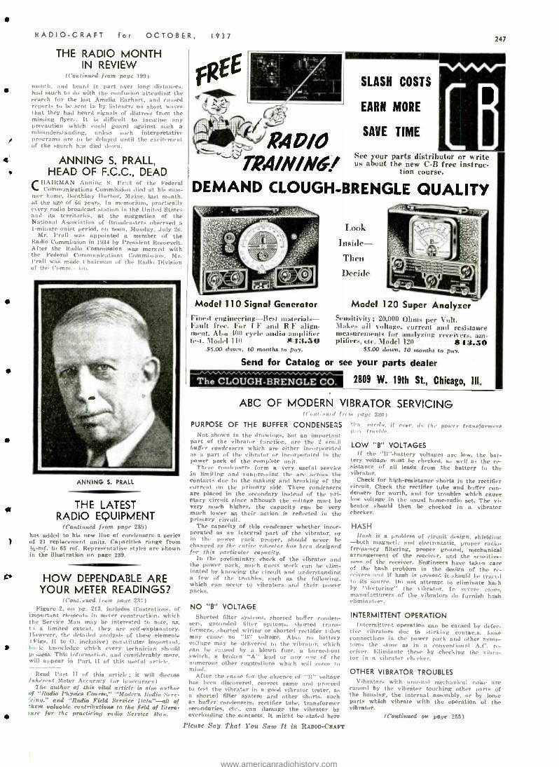
RADIO -CRAFT for OCTOBER,
THE RADIO MONTH IN REVIEW
(Continued from page 199)
month, and heard in part over long distances. had much to do with the confusion attending the search for the lost Amelia Earhart, and caused reports to be sent in by listeners on short waves that they had heard signals of distress from the missing flyers. It. is difficult to imagine any precaution which could goon] against such a misunderstanding, unless such interpretative programs are to be delayed until the excitement of the search has died down.
ANNING S. PRALL, HEAD OF F.C.C., DEAD
CHAIRMAN Alining S. frail of the Federal Communications Commission died at his sum-
mer hume, Buothbay Harbor, Maine, last month, at the age of 66 years. In memorium, practically every radio broadcast station in the United States and its territories, at the suggestion of the National Association of Broadcasters observed a 1- minute quiet period, on noon, Monday, July 26.
Mr. Pratt was appointed a member of the Radio Commission in 1934 by President Roosevelt. After the Radio Commission was merged with the Federal t'mmmnications Commission, Mr. l'rall was made Chairman of the Radio Division of th . Conlin-
1937
R4V'O TRA/N/JVG!
SLASH COSTS
EARN MORE
SAVE TIME
247
See your parts distributor or w rite us about the new C -B free instruc-
tion course.
DEMAND CLOUGH -BRENGLE QUALITY
AWNING S. PRALL
THE LATEST RADIO EQUIPMENT
(Continued f 239) has added to his new line of condensers a series of 21 replacement units. Capacities range from 14 -mf. to 65 mf. Representative styles are shown in the illustration on page 239.
HOW DEPENDABLE ARE YOUR METER READINGS?
(Continued frunt Palm 237) Figure 2, on pg. 213, includes illustrations, of
important elements in meter construction, which the Service Man may be interested to note, as, 1, a limited extent, they are self- explanatory. However, the detailed analysis of these elements (Figs. H to O. inclusive) constitutes important, b :u lo knowledge which every technician should pc ssess. This information. and considerably more, will appear in Part II of this useful article.
Read Part II of this article; it will discuss Inherent Meter Accuracy (or inaccuracy).
The author of this vital article is also author of "Radio Physics Course." "Modern Radio Serv- cing," and "Radio Field Service Dala "-all of 'hem valuable contributions to the field of litera- ture for the practicing radio Service Man.
Model 110 Signal Generator Finest engineering -Best materials - Fault free. For 1 F and R F align- ment. Also 400 cycle audio amplifier lest. Model 110 $I :1.50
$5.00 amen, It) months to pay.
Send for Catalog
T.t)tlk
Model 120 Super Analyzer Sensitivity; 20,000 Ohms per Volt. Makes all voltage, current and resistance meaurements for analyzing reeeiv,r*.:mt plifier,, etc. Model 120 S 13.50
$5.00 down, to months to pay.
or see your parts dealer
The CLOUGH- BRENGLE CO. 2809 W. 19th St., Chicago, III.
ABC OF MODERN VIBRATOR SERVICING (rr,,t : sal t ,e, )at,, 220)
PURPOSE OF THE BUFFER CONDENSERS Not shown in the drawings, but an important
part of the vibrator function, are the 2 small buffer condensers which are either incorporated as a part of the vibrator or incorporated in the power pack of the complete unit.
These condensers form a very useful service in limiting and suppressing the arc across the contacts due to the making and breaking of the current on the primary side. These condensers are placed in the secondary instead of the pri- mary circuit since although the voltage must be very much higher, the capacity can be very much lower as their action is reflected in the primary circuit.
The capacity of this condenser whether incor- porated as an integral part of the vibrator, or in the power pack proper, should never be changed as the entire vibrator has been designed for this particular capacity.
In the preliminary check of the vibrator and the power pack. much guess work can be elim- inated by knowing the circuit and understanding a few of the troubles, such as the following. which can occur to vibrators and their power packs.
NO "B" VOLTAGE Shorted filter systems, shorted buffer conden-
sers, grounded filter systems, shorted trans- formers, shorted wiring or shorted rectifier tubes may cause no "It" voltage. Also, no battery voltage may be delivered to the vibrator, which can be caused by a blown fuse, a burned -out switch, a broken "A" lend or any one of the numerous other suggestions which will come to mind.
After the cause for the absence of "B" voltage has been discovered, correct same and proceed to test the vibrator in a good vibrator tester, as a shorted filter system and other shorts, such as buffer condensers, rectifier tube, transformer secondaries, etc., can damage the vibrator by overloading the contacts. It might be stated here
Please Say That You Saw ft in RADIO -CRAFT
tln' rarely, if ever, d, the poorer transformers pire trouble.
LOW "B VOLTAGES If the "It- battery voltages are low, the bat-
tery voltage must be checked, as well as the re- sistance of all leads from the battery to the vibrator.
Check for high -resistance shorts in the rectifier circuit. Check the rectifier tube and buffer con- densers for worth, and for troubles which cause low voltage in the usual home -radio set. The vi- brator should then be checked in a vibrator checker.
HASH Hersh is a problem of circuit design, shielding
--both magneti., and electrostatic, proper radio- frequency filtering, proper ground, mechanical arrangement of the receiver, and the sensitive- ness of the receiver. Engineers have taken care of the hash problem in the design of' the re- ceivers and if hash is present it should be traced to its source. Do not attempt to eliminate ha,h by "doctoring" the vibrator. In severe cases, manufacturers of the vibrators do furnish hash eliminators.
INTERMITTENT OPERATION Intermittent operation can be caused by defec-
tive vibrators due to sticking contacts, loose connections in the power pack and other symp- toms the same as in a conventional A.C. re- ceiver. Eliminate these by checking the vibra- tor in a vibrator checker.
OTHER VIBRATOR TROUBLES Vibrators with u n us wl mc_h :n iral noise are
caused by the vibrator touching other parts of the housing, the internal assembly, or by loose parts which vibrate with the operation of the vibrator.
(Continued on page 255)
www.americanradiohistory.com
248
Triumph 1", 2 ", and 3"
OSCILLOGRAPH
WOB BULATORS Buy your oscillograph and wobbula- tor together! Only with this com- bination can you accomplish true visual alignment of r -f, i -f, afc, and avc circuits. Model 77, I" Oscillo- graph Wobb. $49.95. Model 77, 2" Oscillograph Wo6b. $59.95. Model 180 -800, 3" Oscillograph Wobbula- tor with built -in signal generator $100.00.
TRIUMPH MFG. CO. 4021 W. Lake St. Chicago, Ill. Please send Triumph catalogs
Name Address
City State
_TALK -BAK *
Model TRU t Too
Size -0_" diameter. 3" high
Lasting Wear, Perfect Operation, Attractive Appearance
The most complete, beat -looking Talk -Bak Unit manufactured. A steel cabinet with a taupe suede finish so soft as to protect the finest furniture.
FREE New Technical and
Sales Pamphlet gives complete information regarding all known inter-communication systems. Method of connecting different Talk -Bake Units and full detail information on what they will ac- complish. White for it and be sure to include your distributor's name.
Wright -DeCoster Distributors are always .anxious to cooperate.
WRIGHT-DECOSTER, Inc. -:íi University Ave. St. Past. Minnesota Export Dept. -M. Simons & Son Co.. New York.
Coble Address: "Simontriee." Canadian Representatives:
Wm. F. Kelly Co.. 1207 Say St., Toronto. Ontario Taylor a Pearson, Ltd.. Edmonton. Alberta
e upyrighted
RADIO -CRAFT for OCTOBER, 1937
"AIR- TRACK" SYSTEM OF BLIND LANDING (Cantina. d from papy 202)
Six important improvements have been incor- porated in the Air -Track. Foremost among these are the facts that (1) the equipment has been so
simplified and the design made no compart, that it is portable, slaking it Possibly to lend a pilot in to n safe landing front either end of any run- way on the field; (2) the radio signals. at first liable to deviation and instability, have been made reliable, and a monitoring system installed which indicates to the operator whether accurate signals are being broadcast: 13) both the tornli:rr and the glide putt are quickly adjust- able and. (l) the equipment required in the plane has been made lighter and more efficient.
The principles embodied in this system were originally worked out by an Aeronautics Re- search Division established by the Department of Commerce at the Bureau of Standards. A num- ber of the radio scientists who developed the system at the Bureau have been at work in a
laboratory at College Park Airport near Wash- ington developing the system from its early experimental stages to the point where it is
now practical for air transport. Three years of such development and improvement work have resulted in hundreds of successful landings "under the hood" and landings in fog conditions which interrupted scheduled flying.
Three experimental installations of this curved beam type of landing system have been tested by Department of Commerce pilots, airline pilots and others. These are at College Park, Newark airport, and the municipal airport at Oakland, California. In all, upwards of 1.000 safe instru- ment landings huge been made on these installa- tions.
ELEMENTS OF THE AIR -TRACK SYSTEM
Briefly, the Air -frack system co ris i<t: of two radio beams: (I) a runway localizes which lies down the center of the runway to he used. and (2) a curved glide path which leads the plane down a sloping "track" to a gentle landing on the runway. A single "cross- pointer" instru- ment (2 D.C. meter movements, one operating horizontally and the other vertically, mounted in one case) on the panel (see Fig. A) indicates the plane's position, the vertical needle pointing to the right or left if the plane veers from the center of the runway localizer, and the horizontal needle rising or falling if the plane gets above or below the proper glide path.
At a distance of 10 or 15 miles from the airport (see Fig. B), the pilot picks up the runway localizer signal through his regular com- munications receiver. over which he still re- ceives voice communication, perhaps from the operator in the airport control tower. Lining up his flight along this localiser, which can be made as wide or as narrow as comfortable flying dictates, he approaches the curved beam down which he will glide to the runway. IThe re- ceiver for this glide path is adjusted to the best "gliding angle" of that type of plane.)
Having reached this point, the pilot flies his plane so that the 2 needles cross at right -angles. and this indicates that he is approaching over the exact center of the runway and coming down at the proper, safe gliding angle.
At the edge of the field a marker beacon gives him a signal in his earphones which tells him he is crossing the edge of the field- At this time he is approximately 20 to 30 feet above the run- way, and the balance of the landing consists merely of leveling otT and letting the plane settle.
Hundreds of times, planes with landing speeds as high as 75 miles an hour have been brought down to a spot on the field a few yards square! James L. Kinney, Department of Commerce pilot, as far back as 1933. took off from Wash- ington under the hood Ithat is, he could not see outside the plane, had only his instruments to guide him. and hence was flying "blind "), flew by instrument to Newark airport, and landed by instrument on the experimental installation of this system, on a day when scheduled air trans- port planes were grounded by impossible flying weather.
Transmitting equipment is housed in an or- dinary automobile trailer which is quickly movable to concrete platforms at either end of any runway, where the wheels fit into slots to insure proper location of the apparatus. The transmitters are plugged in to a power outlet and the control tower attendant throws a switch wh!,h puts them into operation.
Please Say That You Saw It in RADIO -CRAFT
USEFULNESS OF "AIR- TRACK" AT CROWDED AIRPORTS
Usefulness of the apparatus for control of traffic at crowded airports has been stressed by pilots who have flown the system. Airline officials have pointed out that if all landings of air trans- port planes were made on this system, even in fine weather. a pilot would never make an unusual landing, no matter what the weather might be.
Despite the thoughtful and serious work of airline operations managers and traffic managers in "staggering" schedules to avoid simultaneous arrival of several airliners at one airport at the same time, the airports at large municipalities are already dangerously crowded at certain times. At one airport today, there are 18 transport planes arriving within the space of an hour. Increasing patronage will only aggravate this problem, and bad weather complicates it to the point of deadly hazard.
It is as if the engineers of a large number of trains were instructed to choose their own track and bring their trains in to a huge station with only the admonition to "be careful and not run into other trains." The airline pilot has two -way voice communication with the airport control tower, and receives all the information available. but he does not have a definite "track" or path to follow which will keep him clear of other approaching aircraft.
A correct blind landing system may have a number of duplicate "tracks ", properly identified. just as are the tracks in a railroad yard. and the approaching pilot's orders will indicate the track he is to use. Eventually, these engineers believe. the "switches" may be set for the ap- proaching pilot. and his plane may be taken over by radio when he is distant from the field. and brought in mechanically to a full instrument landing. This dream is not very nebulous, even today.
COMPARISON OF VARIOUS BLIND - LANDING SYSTEMS
There are no "preceding types" of larding systems prior to the Air -Track. It is based definitely upon the original experiments at the Bureau of Standards. which began in 1927 and 1928. An Aeronautical Development Section of the Department of Commerce, Aeronautics Branch, conducted those experiments. and car- ried them up through various stages of develop- ment to the demonstrations held at Newark in 1933.
As for other landing systems (Most of these systems have been described in past issues of Radio- Craft. -Editor), this is the story. In 1931 or 1932. visitors from Germany were shown the Bureau's developments and after their return to Germany the Lorenz system appeared. This is a refinement and development of one of the phases of the Bureau development.
At Newark, the Bureau installation was fixed in position. giving indication in only one direc- tion. The Lorenz system today is also fixed in one position. If it is desired to give landing guidance on more than one runway, or in more than one direction, the installation must be duplicated. This means that under certain con- ditions, the pilot will be coming in to land over the antenna structure and transmitter houses. These form a positive obstacle, much disliked by pilots. There is also the consideration of the added expense necessary to duplicate these transmitters and antenna arrays and structures.
The Lorenz system also uses a European type of indication. with a kicking needle indicating off- course position. This is strange to American pilot practice and preference, and it requires an appreciable time for interpretation. There is no time available for interpretation in the job of blind landing.
The Lorenz system holds to the fundamental principles of the Bureau system, i.e. the "curved beam ", localizer and marker beacons. It gives the pilot an indication of his position throughout the :approach and landing. However, it is not all contained on the airport. and it has not been developed as far as Air -Track.
The success of the Bureau demonstrations at Newark prompted the duplication of the system at Oakland airport in California. Here, United Airlines. later joined by TWA and American Air- lines, and still later by Bendix, have continued
(Continued on page 255)
t
www.americanradiohistory.com
f
RADIO -CRAFT for OCTOBER, 1937
GET THIS new BOOK ---
FREE! Every Radio Man Can Use
It to Advantage!
THE Editors of RADIO -CRAFT have prepared a special hook for you. The new book -1937
RADIO REFERENCE ANNUAL -is not for sale. but available only to subscribers, both new and old, with a Seven Months' Subscription to RADIO -CRAFT. The price of this Special Offer is only One Dollar ($1.001 -and as an additional saving the book is mailed to you postpaid as well as is the magazine each month. Carefully outlined below is the contents of this new book ; it contains information which every radio man needs. The book contains 64 pages, size 6 x 9, and is replete with illustrations.
Read these Interesting Chapter Headings of
1937 RADIO REFERENCE ANNUAL Receiver Construction
Building 12 -tube All -Wave DX receiver -Ilow to make a modern s -tuba Car Radio set- bullding up 2-tube Beginner's Set, with several different power supplies for various uses -- Constructing a 2 -tube midget set for portable use -How to build a "talking" briefcase-no aerial or ground needed.
Test Equipment -Construction Row to make an "Electronic Eye" output meter -How to construct an ultra -compact universal toll- Ohm- Mllllam- lneter -Plow to make a Resistance -Capacity tester -flow to Build a Pocket Adapter for set testing- Building a Portable Capacity bridge -Construction of a V.T. Volt- meter In compact form -How to Make a Modern Set Analyzer.
r
s
f
Audio and P. A. Equipment ]staking an Audio Bass Booster, using direct coupling- Stow to build and add a Dual -Channel Amplifier to your re+elver-t' nstrueting a high- Fidelity Amplifier -Con- struetion of a 3 -tube A.C.- operated Preamplifier-Funda- mentals of "Decibel Level" and Decibel Cain."
Articles for the Service Man Servicing with the Oscillosrope- Servlctog with a Single Meter -"What's Wrong With Your Radio' chan- Tape'r5 M \'plume t'q¿ cols. and use f rious apes -Ideas for the Service Shop -Aligning All -Knave receivers.
Time and Money -Saving Kinks In this section you profit by the experience of other radio men. These kinks are really valuable 'short- cuts" whirls save much tines and. very often, money. They are "pet" Ideas put into Ira,9i,e Important Articles Which Have Appeared in
RADIO -CRAFT General Interest Article.
Design of Treneformrrs ter ('lass ".U:" and "B" opera - tion -A table of Inter-Electrode Capmdtle: for 30 differ- ent tube types-now to make a Floating-G,-ld 7telay- Cunsuuctlon of a modern Treasure locator-How tu get DS on your All -Wave ltadio- ]taking a 5 -meter Trans- ceiver tor use in car or boat,
New Tubes Developed in 1936 Characteristics of the Newest Itovelvhtg Tubes of all manufacturers, giving uses, rhararteri stiu, present equivalents (if any) tout all pertinent dita.
RADIO -CRAFT 99 Hudson Street New York, N. Y.
RADIO- CRAFT, 99 Hudson St., Now York, N. Y. Gentlemen: Enclosed seu w Ill flroi my remittance of One Dollar 191.001 for which enter my subscription to RADIO -CRAFT Magazine for Seven Months. Send me ARSOLT'TE 1.Y I'It :E. and POSTPAID, my spy d 1937 RADIO REFERENCE ANNUAL
Name
Address
City Stute (Send remittance by check or money order. Resister your letter It you send cash or unused U. S. Postage Stamps -)
RC.1031
NEW INSTRUMENT SPEEDS FREE -POINT TESTING
(Continued from page 225) means of determining circuit conditions accurately since no current is drawn from the circuit under test. Current ranges on present -day testers have been used rather infrequently because of the time and trouble required in making a series connection in the circuit.
THE "CURRENT MEASUREMENT" SYSTEM OF TESTING One of the most difficult parts of a radio set
to test and one that has become the bug -a -boo for Service Men is the A.V.C. and Q.A.V.C. circuits. Most voltmeters placed across these cir- cuits, in order to make a voltage measurement, draw current from them and more or less upset the high -resistance networks present. The pur- pose of these circuits is to control the current in the tubes to which they connect. A current measurement is logical therefore, since it does not upset the A.V.C. and Q.A.V.C. networks whatsoever.
By (1) using an oscillator input at the antenna posts of the receiver, (2) plugging this new instrument into the sockets of the tubes controlled by the A.V.C. and Q.A.V.C. and (3) varying the signal strength put out by the oscillator, the plate current variation will give an absolute indication of the condi- tion of the A.V.C. or Q.A.V A. system.
This method can be used for testing diode 2nd - detector circuits no matter how complicated the resistance networks connected to the diode may be. Fixed minimum bias, A.F.C. or any other similar circuit may be tested by this method of current testing also. Service Men who do not have an oscillator can make the texts by tuning on and off a powerful local station. In the audio end of the set, grid bias may be checked very accurately by taking plate current readings. An overloaded condition of the rectifier tube can be checked easily by the current method for the power pack circuit need not be considered. As an example, it is the usual thing to check rectifier overload conditions by voltmeter read- ings from chassis to rectifier filament or cathode but this does not necessarily give a correct indication for it does not take into consideration whether the negative lead from the power trans- former goes directly to chassis or through a filter or resistor network before connecting to the chassis. This especially applies in A.C.-D.C. sets.
A couple of examples where current readings come in handy are first, where an audio bias resistor has been so badly burned up that its resistance value can no longer be read. A quick estimate using Ohm's Law will give the approxi- mate value but only by taking current readings of the tube controlled by this bias resistor is it possible to be sure that the resistor value is correct. Another example is in replacing a volume control in an orphan set. By taking current readings of the tube controlled it is possible to check very quickly whether or not the taper of the new control is correct.
To sum up. by the use of the current method of making tests, analyses of radio receiver faults are very much simplified. By use of this instru- ment current readings can be taken simply and without the cutting or unsoldering of wires. (Incidentally, this device also may be used in taking the "usual" tests such as voltage and resistance.)
Our Information Bureau will gladly supply manufacturers' names and addresses of any items mentioned in 71- 4D104'1í:1 FT. Phase enclose a stamped and to If -o11 r,sx.d , n e, lope,
OPERATING NOTES (Continued from page 227)
eral small holes are provided in the top of the container to act as safety valves. in case this action takes place. This small leakage does not affect the efficiency or change the value of the condenser in any way.
STRIMaeltC,- CARLJON SOLgER NI,GGErs
Fada KA and U. S. Radio Model 10. Gassy 27s cause trouble in different sets in different ways. In a Fada KA. 2 of these tubes in the A.F. stage caused very poor quality of reproduction. In a U. S. Radio model 10, a gassy 27 in the 1st audio stage may cause a "jumpy" volume control.
PAUL. WELA ND
Please Say That You Saw It in RADIO -CRAFT
249
CO- ORDINATED
SOUND SYSTEMS ~FO.
MAN 4 \ POWER 1 MI6 O I VII
' - - /. L JI
` Ifjill ` JJ a I _
I{II111
The LAFAYETTE line, one of the oldest. most complete lines in the industry, always meant progress ... but never much as in these NEW 1938 models. colors... stream -lined designs ... lightweight, sturdy, non -corrosive steel cabinets ... special illuminated control dials ... here are features that make for EASY SELLING.
for a wider margin of
has so
New
sales
profit
LAFAYETTE byword of satisfied users
``
t
.If
EASY TIME PAYMENT PLAN] NOW .. LAFAYETTE'S Easy Payment Plan, tailored to the needs of your business, will help
you finance the "big" jobs.
HERE IT IS! FREES The Biggest 0/0
.. Radio Ale I /rOff ,/ +e Op, O
... ,: _ Catalog n
% /ba óntosteD leH ever assembled! 130 pages, R'5C oy,s. adon ero; /s
ecttion. large
parts, 50 the yOCAT,q FRÉ6 LAFAYETTE Radio models. ° 'ri+ey s4orf0G. test equipment ... and all at r e o/ lowest prices in history.
ill11011S11111111010 SEl1VICC CD.c. NEWYORK,N.Y. CHICAGO,ILL ATLANTA, GA. 00 uS IH a0l PI 02 rot W. 141510. 5405. .mw. NACHnn ...NAM
BOSTON, MASS. NEWARK, N. J. BRONX, N.Y. JAMAICA. L I.
WHOLESALE RADIO SERVICE CO.. INC. 100 Sixth A New York, N. Y.
hush FREE 1938 catalog No. 69-3KA
NAME
ADDRESS
CITY. STATE
www.americanradiohistory.com
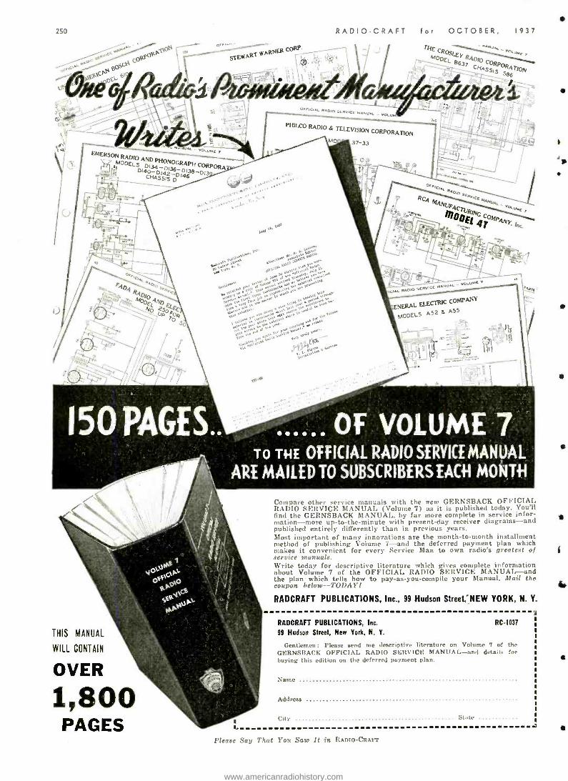
250
ttAON I
O 1 57E`MART WARNS
C
RADIO -CRAFT for OCTOBER, 1937
Tit CRostEr
r"-----()_°4.1- 863 CORPO let -'gin CNASStS ST1pN
6
1 .
.15
r a; Vow
p1D34PHONOGPH CORPORA
D140-D1423 p 13eDI'- .. CHASSIS D
Oir/CIAL RADIO SERVICE MANUAL
PHILCO RADIO & TELEVISION CORPORATION
37 -33
EIC,A' RACIp
MAN
m fnrlc4E fe. MP "^Y
t". tritrta >nE.
150 PAGES ...... OF VOLUME 7 TO THE OFFICIAL RADIO SERVICE MANUAL
ARE MAILED TO SUBSCRIBERS EACH MONTH
THIS MANUAL
WILL CONTAIN
OVER
1,800 PAGES
Compare other service manuals with the new GERNSBACK OFFICIAL RADIO SERVICE MANUAL (Volume 7) as it is published today. You'll find the GERNSBACK MANUAL, by far more complete in service infor- mation -more up -to -the- minute with present -day receiver diagrams -and published entirely differently than in previous years. Most important of many innovations are the month -to -month installment method of publishing Volume 7 -and the deferred payment plan which makes it convenient for every Service Man to own radio's greatest of service manuals. Write today for descriptive literature which gives complete information about Volume 7 of the OFFICIAL RADIO SERVICE MANUAL -and the plan - which tells how to pay -as -you- compile your Manual. Mail the ro upo n below-TODAY'I
RADCRAFT PUBLICATIONS, Inc.. 99 Hudson Street. "NEW YORK, N. Y.
RADCRAFT PUBLICATIONS, Inc. RC 1037
99 Hudson Street, New York, N. Y.
Gentlemen: Please send me descriptive literature on Volume 7 of the GERNSBACK OFFICIAL RADIO SERVICE MANUAL -and details for buying this edition on the deferred payment plan.
Name
Address
City ...
Please Say That You Sau' It in RADIO -CRAFT
www.americanradiohistory.com
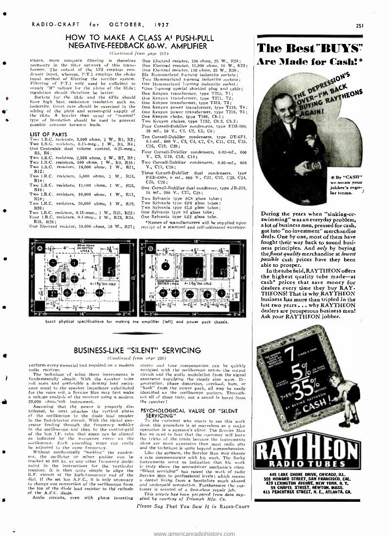
RADIO -CRAFT for OCTOBER, 1937
HOW TO MAKE A CLASS AI PUSH -PULL NEGATIVE -FEEDBACK 60 -W. AMPLIFIER
(Continued from page 215)
stages, more adequate filtering is therefore necessary in the filter network of this trans- former. The output of the 5Z3 employs con- denser input, whereas, I'.T.1 employs the choke input method of filtering the rectifier system. Filtering of P.T.1 only need be sufficient to supply "B" voltage for the plates of the 6L6s; regulation should therefore be better.
Sockets for the 6LGs and the GF6s should have high heat resistance insulation such as, isolantite. Great care should be exercised in the wiring of the plate and screen -grid supply of the 61.6s. A heavier than usual or "normal" type of insulation should be used to prevent possible arc-over between leads.
LIST OF PARTS Two I.R.C. resistors, Two I.R.C. resistors, One Centrelab dual
R5, R6; Two I.R.C. resistors, Two I.R.C. resistors, Two I.R.C. resistors,
R12; Two I.R.C. resistors,
R14; Two I.R.C. resistors,
R16: Two I.R.C. resistors,
R18; Two I.R.C. resistors,
R20; Two I.R.C. resistors, Four I.R.C. resistors,
R25, R26; One Electrad resistor,
3,000 ohms, 2 W., RI, R2; 0.15 -meg., 1 W., R3, R4;
volume control, 0.25 -meg.,
2,500 ohms, 2 W., R7, RS; 500 ohms, 1 W., 119, R10; 10,000 ohms, 1 W., R11,
5,000 ohms, 1
15,000 ohms, 1 W., R15,
10,000 ohms, 1 W, R17,
One Electrad resistor, 100 ohms, 25 W., R28: One Electrad resistor, 15,000 ohms, 50 W., R29; One Electrad resistor, 150 ohms, 25 W., R30; Six Hammarlund ft -prong isolantite sockets; Two Hammarlund 4 -prong isolantite sockets; One Hammarlund 7 -prong isolantite socket; One 7 -prong special shielded plug and cable;
One Kenyon transformer, type T255, T1: One Kenyon transformer, type T271, T2; One Kenyon transformer, type T319, T3; One Kenyon power transformer, type T215, T4: One Kenyon power transformer, type T216, T5; One Kenyon choke, type '1166, Ch.1; Two Kenyon chokes, type T152, Ch.2, Ch.3; Four Cornell -Dubilier condensers, type ED3 -100,
10 mf., 50 V., Cl, C2, C5, CO ;
Ten Cornell -Dubilier condensers, type DT -6P1, 0.1 -mf., 600 V., C3, C4, C7, CS, C11, C12, C15, C16, C19, C20;
Four Cornell -Dubilier condensers, 0.02 -mf., 600 V., CO, C10. C13, C14;
Two Cornell -Dubilier condensers, 0.05 -mf., 600 V.. C17, C18;
Three Cornell -Dubilier dual condensers, type W., R13, PE13-650x, ft mf., 600 V., C21, C22. C23, C24.
C25, C26; One Cornell -Dubilier dual condenser, type JR -216,
16 mf., 200 V., C27. C28; Two Sylvania type 6C8 glass tubes; Two Sylvania type 6F6 glass tubes; Two Sylvania type 6L6 glas tubes; One Sylvania type 53 glass tube; One Sylvania type 5Z3 glass tube.
*Names of manufacturers will be supplied upon 10,000 ohms, 50 W., 527; receipt of a stamped and self -addressed envelope.
50,000 ohms, 1 W., R39,
0.15-meg., 1 W., 521,1122; 0.1-meg., 1 W., R23, R24,
Exact physical spec'lcations for ma g the arnp.:fier (left) and power pack chassis.
BUSINESS -LIKE "SILENT" SERVICING 1COP, li,nud lro,n ,.r,r 2iiL)
perform every essential test required on a modern radio receiver.
The technique of using these instruments is fundamentally simple. With the speaker voice coil open and preferable n dummy load resist- ance equal to the speaker impedance substituted for the voice coil, a Service Man may first make n voltage analysis of the receiver using a modern 20,000 ohms/volt instrument.
Assuming that the power is properly dis- tributed, he next attaches the vertical plates of the oscilloscope to the diode load resistor in the 2nd -detector circuit. With the signal gen- erator feeding through the frequency wobbles in the oscilloscope and then to the control -grid of the last I.F. tube, that stage can be aligned as indicated by the resonance curve on the oscilloscope. Each preceding stage can easily be adjusted to the same frequency.
Without mechanically "rocking" the conden- ser, the oscillator or mixer padder can be tracked at 600 kc. or any other frequency desig- nated in the instructions for the particular receiver. It is then quite simple to align the R.F. circuit at the high -frequency end of the dial. If the set has A.F.C., it is only necessary to change one connection of the oscilloscope from the top of the diode load resistor to thé cathode of the A.F.C. diode.
Audio circuits, even with phase inverting
stages and tone compensation can be quickly analyzed with the oscilloscope across the output circuit and the audio modulation from the signal generator supplying the steady sine waive. Re- generation, phase distortion, overload, hum, or "hash" from the power pack, all may be easily identified on the oscilloscope pattern. Through- out all of these tests, not a sound is heard from the pinker!
PSYCHOLOGICAL VALUE OF "SILENT SERVICING"
To the customer who wants to see this work done, this procedure is as marvelous as a major operation in a surgeons clinic. The Service Man has no need to fear that the customer will learn the trieks of the trade because the instruments alone are more expensive than most radio sets and the technique is quite beyond comprehension.
Like the surgeon,. the Service Man may charge n rate commensurate with his work. The flashy instruments serve as indication that his work is truly above the screwdriver mechanic's class. "Silent servicing" has raised the work of radio Service Men to professional levels; which means a decent living from a heretofore much abused and underpaid occupation. Furthermore the cus- tomer is assured of a first -class repair job.
This artirle has been prepared front data *ap- plied by courtesy of Triumph Mfg. Co.
Please Say That You Saw It in RADIO-CRAFT
251
The Best "BUYS'' Are Made for Casli! *
t RSS'ON
vtvtMßÁ ONS
évy G1b GAIN1
*By CASH" we mean your jobber's regu- lar terms.
During the years when "sinking -or- swimming" was an everyday problem, a lot of business men, pressed for cash, got into "no investment" merchandise deals. One by one, most of them have fought their way back to sound busi- ness principles. And only by buying the finest quality merchandise at lowest possible cash prices have they been able to prosper.
In the tube field, RAYTHEON offers the highest quality tube made -at cash' prices that save money for dealers every time they buy RAY - THEONS! That is why_RAYTHEON business has more than tripled in the last two years . .. why RAYTHEON dealers are prosperous business men! Ask your RAYTHEON jobber.
nA Vllló RADIO TUBES 445 LAKE SHORE DRIVE, CHICAGO. ILL.
555 HOWARD STREET. SAN FRANCISCO. CAL 420 LEXINGTON AVENUE. NEW YORK, N. Y.
55 CHAPEL STREET, NEWTON. MASS. 415 PEACHTREE STREET. N. E., ATLANTA. GA.
www.americanradiohistory.com
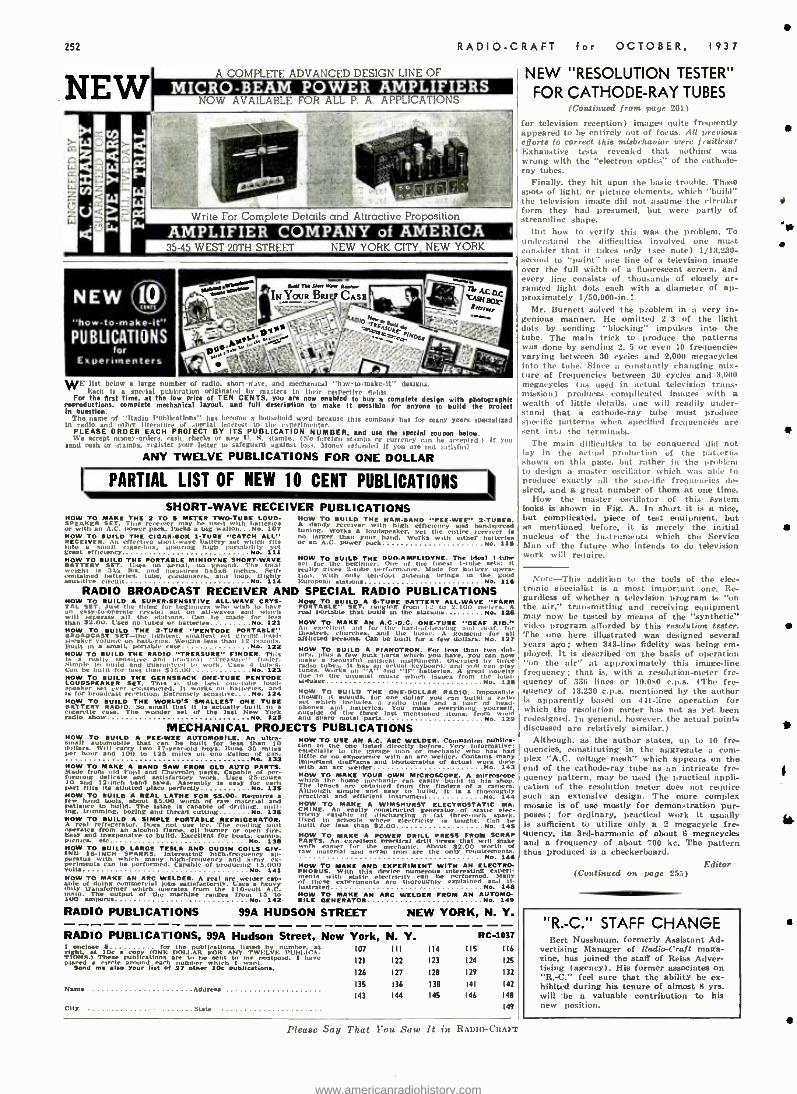
252
NEW RADIO -CRAFT for OCTOBER, 1937
A COMPLETE ADVANCED DESIGN LINE OF
MICRO -BEAM POWER AMPLIFIERS NOW AVAILABLE FOR ALL P. A. APPLICATIONS
Write For Complete Details and Attractive Proposition
AMPLIFIER COMPANY of AMERICA 35 -45 WEST 20TH STREET NEW YORK CITY, NEW YORK
NEW 1V "how -to- make -it" PUBLICATIONS
for Experimenters
WE list below a large number of radio, short -wave, and mechanical "low- to-make-it" designa. Each is a special publication originated by masters in their respective fields.
For the first time, at the low price of TEN CENTS. you are now enabled to buy a complete design with photographic reproductions, complete mechanical layout, and full description to make it possible for anyone to build the protect In question.
The name of "Radio Publications" has become a household ord because this company has for many years specialized In radio and other literature of .pedal interest to the experimenter.
PLEASE ORDER EACH PROJECT BY ITS PUBLICATION NUMBER, and use the special coupon below. We accept manes- -orders. rash. cheeks or new IT S. .LIMPS. (No foreign stamps or currency e n be accepted. ) If you
send cash or stamps, register your letter to safeguard against loss. Money refunded if you ate I. ,.1 -ücl ANY TWELVE PUBLICATIONS FOR ONE DOLLAR
PARTIAL LIST OF NEW 10 CENT PUBLICATIONS II
SHORT -WAVE RECEIVER PUBLICATIONS NOW TO MAKE THE 2 TO S METER TWOTUBE LOUD. HOW TO RUILD THE NAMAND "PEE -WEE" 2- TUBER. SPEAKER SET. This receiver he used with batteries A dandy receiver with high efficiency and hamtspread with A C erect eÌh
may tuning. Works a loudspeaker yet the entire receiver is po erpa c a tg wa of o
HOW TO BUILD THE CIOAR -SOX 1 -TUÉE "CATCH ALL" no larger than your hand. Works with either butteriez RECEIVER. An effective short -wave battery set which fits or an A.C. power pack No. 115 into aí cf( vinais
agar -box, unstring high portabiNOy yet
a
MOW TO [MILD THE PORTABLE MINIDYNE SHORT -WAVE MOW TO RUILD THE DUO- AMPLIDYNE. The Ideal 1 -tube Uses 110 aerial. nd. The 1
for the beginner. One of line finest 1-tube stets: it weight is 3t/ IDs, a measures w5 x,3 inches.
total really gives 2 -tube performance. Made for battery opera contained batteries, tube, condensers. and loop. IlighlY Don- With only [nlout entpta 4rltngs ut the good sensitive circuit No. 114 turopomn stations No. 115
RADIO BROADCAST RECEIVER AND SPECIAL RADIO PUBLICATIONS HOW TO BUILD A SUER -SENSITIVE ALL -WAVE CRYS- HOW TO ROILS A -TUBE BATTERY ALL -WAVE "FARM TAL SET. Just the thing for ',manners who wish to have PORTARLE" SET. ranging from 12 tu 2.100 meters. A an asy.to. operate crystal sut ail -waves and winch real portable that pulls in Use alatluua......... No. 8126 will separate all the striions. Can be made for less than $2.00. Uses no tubes or batteries No. 121 HOW TO MAKE AN A.C.-D.C. ONE -TUBE "DEAF AID." HOW TO BUILD THE 2-71111E ',PENTODE PORTABLE An excellent aid for Om hanl.ofDearing and deaf. for SROADCAST SET -the lightest. test. a allest set giving I 1 theatre, churches. . d lue home. A godsend for speaker volume on Mtleries. Weighs less than 12 mono.. afflicted persona. Can be built fur :, few dollars. No. 127 Built an a IL portable case No 112 HOW TO SUMP A PIANOTRON. For less than t.vn dol. HOW TO SUILD THE RADIO TREASURE" FINDER. This lars. plus a few lank sparts which you have. you can is a really sensitive amt practical 'Tri sun finder. make a beautiful musical instrument. Aerated In- three Simple tu bulled and guaran1av,I 1 work. Uses 4 tubes. radin tubes. It has al actual keyboard. I you , play Can be built for less limn 313.00 No. 123 tunes. Warka n A "' and n" batteries.
and great no it
NOW TO BUILD THE GERNSBACK ONE -TUSE PENTODE due ln the unusual music which issues from the loud- NOW SET. This as the best one-tube loud- speaker
n
Ho. 12S
is fkaI, t ver constructed. Il works oit batteries. A MOW TO BUILD THE ONE -DOLLAR RADIO. imposa ihle ur broadcast reception. Extremely sensilive NO. 324 thiugh it nds, for one dollar you can build radio HOW TO BUILD THE WORLD'S SMALLEST ONE TUNE set which Ìm-lptes a radio tube and a pair of head - BATTERY RADIO. 11 that it i actually built ha phones and batteries. You make everything 't
from wood cigarette radio
c . The So
set of the last New York ide of the three last mentioned items. sl radio shuwas No. 125 and spare metal parts No. w129 MECHANICAL PROJECTS PUBLICATIONS
MOW TO BUILD A PEE-WEE AUTOMOBILE. An ultra - I1 automobile that ran be built for less than 10 dollars. Will carry two 17- year -old boys. Runs 35 miles
Per hour and 100 to 125 miles on one gallon Ne es, of Ì
HOW TO MAKE A SAND SAW FROM OLD AUTO PARTS. Made eon] Chevrolet par. Capable of
delicate and satisfactory Uses 25-gauge JO and 12.inch band saws. Assembly la easy for each port tills Its allotted place perfectly No. 135 NOW TO BUILD A REAL LATHE FOR 55.00. Requires few hand tools. about 55.00 worth of material d patience to build. The lathe is capable
raw ill - g. trimming. boring and thread cutting No. 135
AHOW TO refrigerator. Does
SIMLri useeAIce. The
F cooling unit
Easy Band from
nexpensive to obus d. Excellent for boats. e fire.
Picnics. etc No. a 13S HOW TO BUILD LARGE TESLA AND OUDIN COILS GIV- IHO IS -INCH . Interesting highfre,iuency ali. parata with which many mgt- fre.luency and x y - pei"enÑ can be performed. Capable of producing
t15.000 HOW TO MAKE this
NDdEXPERIMENT WITH AN EELECTRO.
HOW TO MAKE AN ARC WELDER. A 1 a welder p- n with experiments
static lecctricitvuman be performed. Mane able of doing commercial fobs satisfactorily. Uses heavy re iñese re thoroughly laced nn D-
uty transformer which operates from the 110 -volt A.C. Ìualrated No. 1{B in. The output of the machine ranges from 15 to HOW TO MAKE AN ARC WELDER FROM AN AUTOMO
UM amperes No. 142 RILE GENERATOR No. 149
RADIO PUBLICATIONS 99A HUDSON STREET NEW YORK, N. Y.
HOW TO USE AN A.O. ARC . Companion publica- tion o the on listed directly before. Very Informative: .specially to the garage mechanic who has had especially
ex rienre with welder. Contains many imis,rtant. no
and photographs of actual work done with an welder No. 143 HOW TO MAKE YOUR OWN MICROSCOPE. A microscope which the home mechanic can easily build in his shop. The lenses are obtained from the finders of a cam. Although simple and easy to build. It is a thoroughly practical and efficient instrument No. 144 HOW TO MAKE A WIMSHURST ELECTROSTATIC MA. CHINE. An easily constructed tn,cted generator of nt. lie elec- tricity callable f discharging a fat three -melt spark. Used In schools where electricity is taught. can be built for less than $2.00 No. 145 NOW TO MAKE A POWER DRILL PRESS FROM SCRAP PARTS. An excellent practical drill n that will make work easier ñn the mechanic. About $2.00 worth of raw material and scrap iron are the only re,luirements
No. 145
RADIO PUBLICATIONS, 99A Hudson Street, New York, N. Y. RC -1037 I enclose s f a. the publication. listed by m ber at 107 I I I right, t loe a y (ONE DOLLAR FOR ANY TWELVE: lUH1.ICA- TIONS.) These áuDlléatlens are be be sent t m postpaid. I have
121 122 Placed Snd a me also your list of number tr which
publications.
Name Address
city State
126 127
135 136
143 144
114
123
128
138
145
I IS
124
129
141
146
116
125
132
142
148
149
Please Say That You Saw It in RADIO -CRAFT
NEW ''RESOLUTION TESTER"
FOR CATHODE -RAY TUBES
for television reception) images quite frequently appeared to be entirely Out of focus. AU previoua efforts to correct this misbehavior were fruitless! Exhaustive tests revealed that nothing was wrong with the "electron optic,' of the cathode- ray tubes.
Finally, they hit upon the basic trouble. Those spots of light, or picture elements, which "build" the television image did not assume the circular form they had presumed, but were partly of streamline shape.
But how to verify this was the problem. To understand the difficulties involved one must consider that it takes only (see note) 1/13,230 - second to "paint" one line of a television image over the full width of a fluorescent screen, and every line consists of thousands of closely ar- ranged light dots each with a diameter of ap- proximately 1/50,000-in. I
Mr. Burnett solved the problem in a very in- genious manner. He omitted 2/3 of the light dots by sending "blocking" impulses into the tube. The main trick to produce the patterns was done by sending 2. 5 or even 10 frequencies varying between 30 cycles and 2,000 megacycles into the tube. Since ti constantly changing mix- ture of frequencies between 30 cycles and 3,000 megacycles (as used in actual television trans- mission) produces complicated images with a wealth of little details, one will readily under- stand that a cathode-ray tube must produce specific patterns when specified frequencies are sent into the terminals.
The main difficulties to be conquered did not lay in the actual production of the patterns shown on this page, but rather in the Problem to design a master oscillator which was able to produce exactly all the specific frequencies de- sired, and a great number of them at one time.
How the master oscillator of this system looks is shown in Fig. A. In short it is a nice, but complicated, piece of test equipment, but as mentioned before, it is merely the initial nucleus of the instruments which the Service Muir, of the future who intends to do television work will require.
Note -This addition to the tools of the elec- tronic specialist is a most important one. Re- gardless of whether a television program is "on the air," transmitting and receiving equipment may now be tested by means of the "synthetic" video program afforded by this resolution tester. The one here illustrated was designed several years ago; when 343 -line fidelity was being em- ployed. It is described on the basis of operation "on the air" at approximately this image-line frequency; that is, with a resolution -meter fre- quency of 336 lines or 30,080 c.ps. (The fre- quency of 13,230 c.p.a. mentioned by the author LS apparently based on 441 -line operation for which the resolution meter has not as yet been redesigned. In general, however. the actual points discussed are relatively similar.)
Although, as the author states, up to 10 fre- quencies, constituting in the aggregate a com- plex "A.C. voltage mesh" which appears on the end of the cathode-ray tube as an intricate fre- quency pattern, may be used the practical appli- cation of the resolution meter does not require such an extensive design. The more complex mosaic is of use mostly for demonstration pur- poses; for ordinary, practical work it usually is sufficient to utilize only a 2 megacycle fre- quency. its 3rd- harmonic of about 6 megacycles and a frequency of about '700 kc. The pattern thus produced is a checkerboard.
Editor (Continued on page 255)
"R.-C." STAFF CHANGE Bert Nussbaum, formerly Assistant Ad-
vertising Manager of Radio-Craft maga- zine, has joined the staff of Reiss .Adver- tising (agency). His former associates on "R. -C." feel sure that the ability he ex- hibited during his tenure of almost 8 yrs. will -be a valuable contribution to his new Position.
a
www.americanradiohistory.com
f:s
RADIO -CRAFT for OCTOBER, 1937
Formerly Sold for
$15,00
VARIABLE speed induc-
tion typo .self- starting. Ili) all, 25 to 60 cycle, AC. with speed control. Plug and cord. Speed range from 5 to 200 RPM. Can be installed in ()lace of old-fashioned. hand - winding speed motor. Outside Diane. 11 ". height Shaft IVs". (Clam. 54') O.E. Electric Phonograph motor as de- S A .95 scribed
Sin going weight -12 Ib..
WESTINGHOUSE UNIVERSAL MOTOR
$x.55 Shipping
Weight 3 tbs.
ions, 1/30 11 I' Ir:d(- porates on either A.C. or 11.1'., 110 volts. 5000 R.P.51. Rheostat can be used to vary spin i Height :iW, Length 3 % ". Width 1%', Shaft t/s'. ono Inch long. Can be used to drive Sewing Machines, Mod- els. Buffing lathe. roil.hing ]toad, Drills. Grindstones. etc.. etc.
110 Volts AC sad OC
MOTOR only $2.55
MOTOR with Arbor ar.1 11" Chuck á355
Add 25c for sperint packfng and mailing anywhere ro 11. S. A.
MICROPHONE and RECEIVER TAANSMarrn EAR CAPE "rat
SET
pause NATE
2e rt EASY
Ana <ete
TWO CIRCUIT JACK
Tins Microphone and telephono headset outfit was built especially for the U. S. Navy Aviation Corps. The Holtzer -Cabot Electric Company constructed the
outfit to Government specifications. The outfit consists of a low -impedance carbon micro-
phone (transmitter). securely fastened to a metal breast- plate. and a set of heavy -duty. low- linbedanco earphones. A specially constructed switch on the back of the breast- plate controls the microphone circuit. Tho earphones are U.S.N. Utah type, attached to adjustable headband. Twenty -eight feet of very heavy weather and waterproof omducmr cable is furnished. Current of not more than 10 volts should be used. A storage battery is the most satis- factory current irpf supply. f'. S. Navy Airplane-type Microphone and .iaa an
Rendctr a= ae,crwca Tne shaping weight is g Iba.
d WESTINGHOUSE POWER GENERATOR
Manufactured for U. S. Signal Corps
A.C. Electrical 200Watt IIOV.AC Power
from a Windmill. from aval table Waterpower, from your Automobile. from your Motorcycle. from your Bicycle, Foot - pedals Handerank Ifor transportable Radio Transmitters. S t r o n g Floodlights, Advertising Signs); do you want to operate AC Radio s is from 32 V. DC farm (,gut systems; operate
r phase °an generators
phases AC. to
et . 1 toci' lit, needed led to run There Are Over 25 Applications, such as: A.C. Dynamo light from eight to ten 20 watt 110 Volt lam. Short Wave Transmitter supplying 110 volts A.C. for operating "Ham" transmitter. operating 110 V. AC 00 Cycle Radio Receiver in DC districts. Motor Generator. Public Address
Systems. Eltectrictc irens on motor boats. yachts, etc. Camp
Blue -('riot 22 a 2a In. and Four-Page `rra9 desdescribed lInclud ,lire fours replacement -7 brushes
re err
Shipping weight IS Ms.
All merchandise in original packages - never used. Money -back guarantee.
We will forward Shipments by Express Collect if sufficient postage is not included.
WELLWORTH TRADING CO. 560 W. Washington Blvd., Dept. RC -1037, Chicago,lll.
IMPORTANCE OF MODERN TEST EQUIPMENT (Continued from page 207)
audible range. This type of equipment will allow the Service Man to check the response char- acteristics of the receiver from the antenna term- inal to the input of the loudspeaker, giving in- dications of the quality which may be expected.
New opportunities are periodically being pre- sented to the Service Man due to the fact that developments are continuously being made, and the public is becoming more aware of what it may expect in the way of radio reception. At the present time the set owner is beginning to realize that much of the radio interference which he was formerly led to believe was a necessary evil may be mitigated or entirely elim- inated by filtering apparatus which causes radio noise. The Service Man who has made some study of this type of man -made static is in a good position to pick up much profitable business.
Public - address systems have long been more or less neglected by the average Service Man as an added source of income. A thorough acquaint- ance with the circuits commonly employed ea well as the ordinary troubles encountered in this type of apparatus is well worthwhile.
THE ABC OF A RESONANCE CURVE To return to the cathode-ray oscilloscope as a
means of obtaining a visualization of the reso- nance curve, it might be of interest to show the manner in which a curve is actually traced on the screen. In order to obtain such a curve it is necessary to have a frequency -modulated signal generator.
Frequency modulation of a signal generator as opposed to ordinary amplitude modulation, where the amplitude of the radio frequency out- put of the signal generator varies at an audible (say 400 cycle) rate, consists of varying the frequency of the signal produced by the signal generator at a given rate, usually 60 cycles. It should be noted that in frequency modulation the amplitude of the signal does not vary with time but the frequency does. Curve B of Fig. 1 shows the manner in which the frequency produced by the signal generator varies over a complete cycle of its frequency range.
'The mode in which the radio receiver responds to a frequency modulated signal must be thoroughly understood. Assume for example that an unmodulated, single -frequency signal were fed into the input of the receiver. When the receiver is tuned to this frequency the RF. amplifier and I.F. amplifier. if the receiver has one, will amplify this un- modulated single fre- quency and a voltage will be built up across the diode detector circuit which is proportional to the amplitude or intensity of the input signal. However, if frequencies other than the fre- quency to which the set was tuned were fed into the receiver, the voltage developed in the diode detector circuit would be smaller in value because of the selectivity of the receiver. The sharper the receiver the more variation in voltage developed in the diode circuit between the resonant frequency and other frequencies higher and lower than the resonant frequency. Curve C of Fig. 1 shows the magnitude of the voltage in the diode circuit as the frequency varies about the frequency to which the set is tuned, which is indicated by point O on the curve.
It will be noted that the frequency modulation of the signal generator as indicated by curve B varies about a mid -point to 15 kc. higher and 15 ke. lower than the middle frequency. For instance, if the mid -frequency is 600 kc., the frequency produced by the frequency -modulated signal generator will vary from 585 kc. to 615 kc., a range of 15 kc. either side of the mid - frequency.
If a connection is made so that the voltage in the diode circuit is fed to the vertical deflect- ing plates of the oscilloscope and the beam is swept horizontally back and forth across the screen at the same rate as the frequency modula- tion (which in this case is 60 cycles) then a resonance curve may be depicted on the cathode - ray screen. The 60 -cycle sweep voltage is shown in curve A of Fig. 1. in order that the pattern on the screen of the cathode -ray oscilloscope will be stationary, the resonance curve must be plotted by the inertialess cathode -ray beam over and over again, falling in the same position on the screen for each successive cycle. Curve D
(Continued on following page)
Please Say That You Saw It ill RADIO -CRAFT
25:
The LAST WORD in
PERFORMANCE . a . R
The Last Word in Long Life!
MODEL 321
TUBE TESTER
MULTITESTER
$4950 Whatever you pay for a tube tester -multi- tester, you can't duplicate comprehensiveness. engineering, performance, of Radio City's new Model 321. Consider these features: Tube tester provides most modern R.M.A. load, separate function, open, short. leakage tests. Absolutely free reference to full floating filaments. Hum and noise tests. Double fuse protection for meter and tester. Multitester tests condenser leakage, opens and shorts, electrolytic paper, mica types. 5 range AC voltmeter 9 -5 -25- 125 -500 -1250. 5 range DC voltmeter- 0 -5 -25- 125 -500 -1250. 5 range ohmmeter -low 1 /20th ohm to high 30 meg- ohms. Current -6 ranges -low 10 microamps, high 25 amps for vibrator testing. D.B. measurements from down 15 to up 40. 5 out-
put ranges. Protect- ed against burn out -and obsolescence. A TUBE
TESTER Set Tester
combination that can't get out of date MODEL 306
$2195 The most flexible instrument of its kind ever pro- duced. Tests all glass and metal tubes now in use, has spare capacity for future new types. Tests each section of Multi -Purpose Tubes and individual plates of all rectifiers. Double test of hot cathode leakage by neon lamp as well as by meter. 250,000 ohms leakage sensitivity. Tests cold cathode recti- fiers which cannot be tested on many higher priced checkers. Full floating filaments. In addition to as these features, measures resistance, capacity and condenser leakage. Attractive design -sturdy con- struction. Guaranteed for 5 years against getting out of date.
Also available in kit form $17.95 See your jobber. Write to Dept. C for Catalog
RADIO CITY) (PRODUCTS CO. 88 PARK PLACE
NEW YORK CITY "DEPEND ON
DEPENDABLE"
(lot off the press! Gltirnrrli's POCKET
TROUBLE SHOOTERS
Send in
Your
1 FOR BOTH GADGETS - MONEY -BACK GUARANTEE!
(51.20 RADIO & TECHNICAL PUBL. CO. foreign) 45 At "r Place, New York
SPEED UP YOUR SER- VICE WORK with these
ìo, tad s. i,, "t ̀tint- Dii, testa
rand andedy fort a:hy
trouble inns receiver. One Ga,tget for 11035E. ono
smo AUTO r 4 0 troubles With lightning speed. The handiest, simplest.
quickest service aid you over PIN A IPOLLA1t 'r0 Tills AD AND MAIL AT ONCE TO DEPT. RC -107.
www.americanradiohistory.com
254
TRANSFORMERS
FOR THIS
100 WATT MODULATOR '122'
HIS inexpensive but efficient modu- T lator delivers 100 clean watts of audio with 800 volts on the plates of the modu- lator tubes. Built on standard Relay Rack and PaneL TUBES: 6C6 Pre -amplifier, 76 voltage amplifier: Push -Pull 76's: 6A3 Drivers: TZ -20 Class B Modulators. STANCOR TRANSFORMERS: Push -Pull Input, XA4206: Push -Pull Interstage, XA4208: Push -Pull Driver, XA4212: Output, XA2908. FREE BLUEPRINT AND LAYOUT TEMPLATE
STANDARD TRANSFORMER CORPORATION tí50 BLACKHAWK ST., CHICAGO
Zew CATALOG OF AMPLIFIERS
All types, embodying I:Ae :t principles of design and construction. Superior quality. Many new features and advan- tages. Superb salles, remarkably low - priced. Used by leading P.A. Men. Write for free catalogue now! AMPLITONE
I1PRODUCTS CO., 135 Liberty St. N.Y.
AMPLI TONE Correspondence Courses In
RADIO 3 d UURKM £NGIN££RING
ELECTRICAL ENGINEERING G" goo group of p ..al fie .1. Prepare yourself. at Low Cost. for secure fu-
Rtor kern. hfi ed.Y you fcan ,rader
fané douicki . ADIOENGINEERING fir ,here,,, pñip-eleiirie a.
furervhe man. real v tithe to, lor r,óuu 6qetá kas furnished. Diploma on completion. Toil u.n, ill,` r cour Deferred payment plan.
FREE r plena chool cale¢¢ tudent magazine,. complete dealte. SEED NOW!
LINCOLN ENGINEERING SCHOOL, Ba 931 -43. LINCOLN, HEIR.
R M C RELAYS cluding P.E. Cell wu k signal aand alarm circuits. etc. Pure silver contacts I
erre rating. 0
0omtes n 3 to 4 M.A.
h rl o 16oethS llistante 1000 ohms-other vaue yid mile.
Dealer Net Price . $2.85 postpaid 25r7c Deposit Require) ou C.O.D.
REGAL MANUFACTURING CO. 1906 S. Grand Ave. Los Angeles. Calif.
RADIO CHASSIS CRADLE For more `afile and
.a receivers o lifierslnL noun service .hop needs the the RAIr1O eGIR- nient )clamps tcradle,.
le Equip- ment
he adjusted to h. x de- sired angle. Conveniently ac- commodates dates a nr chassis '19 21 inches. Excellent for displaying receivers to cut W 'lt f a /wtrated circular RC!
WM. A.THOMAS C0.321 CAROLINEST., NEENAH,WISCONSIN
RADIO -CRAFT for
(Continued from preceding page)
represents the picture which actually appears on the screen under the above conditions.
HOW A CYCLE "PAINTS" ITS IMAGE The intersection of horizontal lines drawn
through points of curve C representing various points in the cycle. with vertical lines drawn through the corresponding points of curve A. determine the pattern which is traced on the screen of the 'scope during a complete cycle.
The reader can readily follow these points as they are numbered consecutively. For instance, at point O the moving spot is in the center of the screen as regards its horizontal position ; at this same instant of time the frequency -modulated signal generator is producing the frequency to which the set is tuned so that the response of the set (applied to the vertical deflecting plates) is a maximum. At point 1 on curve A the spot has moved slightly to the right as regards to its horizontal position. At this instant of time the frequency produced by the signal generator is
slightly higher than the frequency to which the set is tuned and the response is correspondingly lower. The remainder of the picture traced on the screen may be understood by following the consecutive points indicated on the drawing.
THE "SERVICE TECHNICIAN" The Service Man is becoming more and more,
as the years go on, a technician. In the successful pursuit of his work he must have a fundamental understanding of the various principles under- lying each and every individual circuit which goes to make up the radio receiver. These cir- cuits. when individually analyzed. are not ex- tremely difficult. However, they do require a thorough understanding of the operation of each of the component parts entering into the circuit. Not only must the Service Man have a good physical picture of circuit operation, but he must also be thoroughly acquainted with the various types of test equipment which he uses in analyzing receiver faults. He must know the applicability and limitations of this equipment and. as a consequence, he must understand the principles on which it operates.
The standards for efficient Service Men are being constantly raised. Their professional serv- ices should demand increased remuneration. Radio service racketeers are finding that it is becoming increasingly difficult to hoodwink the public. Probably the day will arrive when no Service Man not having a diploma from a creditable school will be allowed to practice.
SERVICING QUESTIONS AND ANSWERS
(Continued from pace 227)
your 4 -tube set. the plate voltage is generally much higher, and this is responsible for the resistor on the primary side of the No. 255 audio transformer burning out.
You ask what the correct voltage should be on the plate- return of the 1st audio stage. It is advisable to "juggle' the voltages from 45 to 135 in order to determine the best results.
Remove the 3 -to-1 audio transformer and re- connect the Silver- Marshall No. 255 unit, for since you only burned -out the primary resistor, it is merely necessary to replace this resistor with one having a value of 0.2 -meg. See Fig. Q27. It is not necessary to open the transformer, to get at the resistor ; merely shunt this resistor across taps 1 and 2, and this unit will be as good as new.
LOUD HUM AND WEAK SIGNALS (!x I Floyd Coomber, Wal worth, N. Y. (Q.) 1 have an RCA model 4 -17 -M set. It has
a loud hum and only faint reception of the nearby. powerful. local stations. Tubes were checked and found to be OK.
(A.) The reason for a loud hum and only faint reception of nearby local stations of your RCA model 4 -17 -M 4 -tube receiver is due to the filter condensers capacities being below their designated rating. The only remedy is to replace these filter condensers. and in doing so, make sure that the correct polarity of the replace- ment condensers is maintained. Voltages will read from 60 to 100 V. on all sockets.
Please Say That You Saw It in RADIO -CRAFT
OCTOBER, 1937
GERNSBACK OFFICIAL RADIO SERVICE
MANUALS AND
HANDIBOOK ARE AVAILABLE AT
* JOBBERS
* DISTRIBUTORS
* MAIL ORDER
HOUSES
Here they are: 1936 Official Radio Service Manual
1.200 PAGES OVER 2.500 ILLUSTRATIONS Looaeleaf Binder -Stiff, Hard t'cpers
Size 9 z 12 Ingle; Pries 67.00
1935 Official Radio Service Manual OVER 1.000 PAGES OVER 3.000 ILLUSTRATIONS Looseleaf Binder -Flexible, Leatherette Corers
Size 9 z 12 Inches Pries $7.00
1934 Official Radio Service Manual OVER 400 PAGES OVER 2.000 ILLUSTRATIONS Looaeleaf Binder- Flexible. Leatherette Cuvcra
Size 9 z 12 Inches Price $3.50
1933 Official Radio Service Manual OVER 700 PAGES OVER 2,000 ILLUSTRATIONS Looaeleaf Bindrr- b'Irrible, Leatherrtr. Corers
Size 9 z 12 hale, Price $5.00
1932 Official Radio Service Manual OVER 1,000 PAGESOVER 2.000 ILLUSTRATIONS
Looaeleaf Binder. Flexible Covers Siac ti z 12 luches 19íko $5.00
1931 Official Radio Service Manual OVER 650 PAGES (Including Supplements)
OVER 1.500 ILLUSTRATIONS Looaeleaf Binder -Flexible, Leatherette Corers
Size D x 12 luches Prim $4.50
1935 Official Auto -Radio Service Manual OVER 240 PAGES OVER 500 ILLUSTRATIONS Looaeleaf (tinder- Flexible, Leatherette Corers
Sine 9 z 12 Ini -lies Price $2.50
1933 Official Auto -Radio Service Manual OVER 250 PAGES OVER 500 ILLUSTRATIONS Looseleaf Binder -Flexible. Leatherette ('opera
Sigo 9 z 12 in -lies Price $2.50
Official Radio Service Handibook OVER 1.000 PAGES OVER 1.000 ILLUSTRATIONS
Beautiful Linea, (old Sta +n nrd corer Size fi z 9 holies Price $4.00
If your Jobber or mail order house cannot supply you. order any of the OFFICIAL RADIO
SERVICE MANUALS or the OFFICIAL RADIO SERY iCE HANDIBOOK from the publishers. Send your remittance in form of check or money order -or. it you send cash or unused U. S. Postage Stamps. be sure to register your letter. ALL ORDERS ARE FILLED PROMPTLY. BOOKS ARE SENT TO YOU POSTAGE PRE- PAID. Address Dept. RC -1037.
RADCRAFT PUBLICATIONS, INC.
99 Hudson Street, New York, N. Y.
s
s
www.americanradiohistory.com
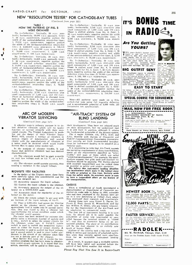
RADIO -CRAFT c- OCTOBER, 1937
NEW "RESOLUTION TESTER" FOR CATHODE -RAY TUBES
TABLE I
HOW THE PATTERNS OF FIG. B WERE OBTAINED
No. 1- Deflection: Vertically. 30 c.p.s. saw- tooth ; horizontally, 10,080 c.p.s. sawtooth. Grid: 1. 30 c.p.s. square -wave, negative portion the width of the vertical - deflection return -line time; 2. 10,080 c.p.s. square -wave, negative portion the width of the horizontal- deflection return -line time; 3. 2,222.640 c.o.s. sine -wave; 4. 740,880 c.p.a, sine -wave; 5. 246,960 c.p.s. square-wave; 6. 70,560 c.p.s. square -wave; 7. 1.260 c.p.a. square -wave; 8. 180 c.p.s, square -wave.
No. 2- Deflection : Vertically, 30 c.p.s. saw - tooth; horizontally, 10,080 c.p.a. sawtooth. Grid: 1. 30 c.p.s. square -wave, negative portion the width of vertical deflection return -line time; 2. 10,080 c.p.a. square -wave, negative portion the width of horizontal- deflection return -line time; 3. 740,880 c.p.s. sine -wave; 4. 246,960 c.p.s. square -wave; 5. 1,260 c.p.s. square -wave.
No. 3- Deflection: Vertically, 30 c.o.s. saw - tooth; horizontally, 3,780 c.p.s. sine -wave plus small component of 1,260 c.p.a. Grid: 1. 30 c.p.s. square -wave, negative portion the width of the vertical- deflection return -line time; 2. 70,660 c.p.s. square -wave.
No. 4- Deflection : Vertically, 30 c.p.s. saw - tooth; horizontally, 3,780 c.p.a. sine -wave plus small components of 1,260 c.p.a. and 180 c.p.s. Phase of horizontal deflection is changed from that in No. 3. Grid: 1. 30 c.p.s. square -wave, negative portion the width of the vertical- deflec- tion return -line time; 2. 70.560 c.p.a. square wave.
No. 5- Deflection: Vertically, 30 c.D.s. saw - tooth ; horizontally, 3,780 c.p.s. sine -wave plus small components of 1,260 c.p.a. and 180 c.p.s. Phase is shifted slightly from No. 4. Grid: 1. 30 c.p.s. square -wave, negative portion the width of the vertical- deflection return -line time; 2. 3,780 c.p.s. sine -wave; 3. 70.560 c.p.a. square - wave.
No. 6- Deflection: Vertically, 30 c.p.s. saw - tooth; horizontally, 3,780 c.p.s. sine -wave plus small components of 1.260 c.p.s. and 180 c.p.s. Phase is shifted slightly from No. 4. Grid: 1. 30 c.p.a. square -wave, negative portion and width of the vertical- deflection return -line time; 2. 3,780 c.p.s. sine -wave: 3. 70,560 c.p.s. square -wave.
No. 7- Deflection: Vertically, 30 c.p.s. saw- tooth ; horizontally, 3,780 c.o.s. sine -wave plus small components of 1,260 c.p.a. and 180 c.p.s. Phase is shifted some from No. 4, is almost same as that for No. 5. Grid: 1. 30 c.p.s. square - wave, negative portion the width of the vertical - deflection return -line time; 2. 70,560 c.p.s. square- Wave ; 3. 246. 960 c.p.s. square -wave.
No. 8- Deflection: Vertically 30 c.p.s. saw- tooth ; horizontally 3,780 c.p.s, sine -wave plus small components of 1,260 c.p.s. and 180 c.p.s. Phase is shifted considerably from No. 4. Grid: 1. 30 c.p.s. square -wave, negative portion the width of the vertical- deflection return-line time; 2. 70,560 c.p.s. square -wave; 3, 246,960 c.p.a. square -wave.
Note -All patterns were made on a 9 -in. cathode-ray tube using full magnetic deflection and a second -anode potential of 6,000 volts. All f rwturncirs are synch ro rt izoI.
ABC OF MODERN VIBRATOR SERVICING
(Continued from. page 247)
A vibrator tester's primary purpose is to de- tact defective vibrators which will no longer function or operate properly with their asso- ciated circuits. The Triplett Laboratory in work- ing out the design of their Vibrator Tester Model 1670, secured a number of vibrator.' in various stages of deterioration and worked closely with the manufacturers of vibrators so a tester could be designed which would enable Service Men to make every needed test.
In the analysis of vibrator trouble, it was found that defective vibrators had two distinct characteristics.
(I) The vibrators would fail to start properly on very low voltage such as 5.6 V. on a 6 -V. battery.
(2) The vibrators would operate unevenly, thus causing a variation in the output voltage.
REQUISITE TEST FACILITIES In toue design of the Triplett tester, these facts
were carefully taken into consideration and the unit was designed to:
(1) Accurately measure the input voltage. (2) Control the input voltage to the vibrator. (3) Accurately measure the output of the vi-
brator on a GOOD -BAD scale. (4) Accurately check the regularity of the vi-
brator on the meter. (5) Check the output voltage in per cent with
an increase, of the input voltage, of 0.5 -V. (6) Place a 5,000-ohm load across the filtering
system so the vibrator would work into the approximate load it works into in normal opera- tion. This was found to give a vibrator test approximating the actual condition under which the vibrator would operate.
The tester has been designed for extreme sim- plicity using a minimum number of sockets and a rota.,, switch to select the proper circuits for the vibrators under test. A D.P.D.T. toggle switch is used to switch the measuring instru- ment in either the input or output. circuits. A potentiometer is used to control the input voltage, and a second switch is used to place buffer con- densers in the circuit of the vibrator when they are not a definite part of the vibrator.
Most Service Men seem not to realize the tre- mendous progress that has been made in vibrator - type power supply systems. It is hoped that this article, therefore, will be useful to these men.
"AIR-TRACK" SYSTEM OF BLIND LANDING (Continued from page 248)
their development. They have not released much on their development. but we understand that it is still fixed in position, although it retains the fundamental principles of the Bureau system.
The 4 major Airlines, AA, TWA, UAL and EAL, meeting with Bureau of Commerce and Federal Communications Comm- isaion representa- tives recently set forth recommended specifica- tions for instrument loading to be adopted on o national scale.
It is interesting to note that Air -Track exceeds the operating requirements of these specifications, meets all the requirements described as "prac- ticable,' and most of those which are called "projected developments." For example, the speci- fientions suggest that glide path and locslizer in- dications should be separate. The Bureau started with separate transmitters and we regard them as essential to safety and proper operation.
We believe this instrument landing situation has implications which make it the biggest story in radio or aviation at this time. Entirely aside from the safety angle, its economic angle is sure to have a tremendous effect on the history of air transportation.
CREDITS When a curtailment of funda necessitated a
discontinuance of Department of Commerce ac- tivities on radio aids to flying in 1933, scientists who had been employed at the Bureau were set up in a new laboratory at College Park where they continued their research and experiments.
Among these men were Comer L. Davies, Dr. Frank G. Kear, Gerald H. Wintermute, and the late William H. Orton, who are largely responsi- ble for the improvement of the Air -Track and its adaptation to commercial needs.
The first job of instrument landing is to save lives. Its second job is to make possible the completion of every trip interrupted or can- celled because the terminal airport is "closed in ". and thus to guarantee flying on an an- nounced schedule. The story of its contributions will be the first chapter in an entirely new epoch of human flight.
Airlines of the country took a big step toward 100% in safety and regularity of scheduled opera- tion when they recently agreed upon specifica- tions for an acceptable instrument landing system.
As a result, it appears that a workable system will have been tested and accepted before the arrival of bad flying weather this winter.
Please Say That You Saw It in RADIO-CRAFT
7rî
IT'S BONUS TIME
IN RADIO'' Are You Getting
YOURS? Tills year -ltuho s bane
ought to pay you a it Boyars-tn. San not, every month. But IS lt i lino, d- uf Sprayberry trained men are e mak- ing that much extra out of in-
rsed salaries, increased profits from their own businesses from sparo -time earnings. So can you.
$175 A MONTH Meet my student Joseph Artr:Nalu
BIG OUTFIT SENT b .ay,
Ì m ne hangs f rroair scierie
Tho Sprayberry course Is entupiste. 1ributorr-a peraran. AI /VANCE!) Includes latest - eut Job. Thanks to aids and spirits' serles of spare -time w.'q;rin¿éreátln ¢ r'dñ, BUSINESS BUILDINGS. Also big to under- PROFESSIONAL OUTFIT OF stand. I'm making REAL RADIO TOOI.ä. Tltl l'LIITT ÿóu ". ñ domiiti.i.! TESTER, 7 -RIDER MANUALS, writes today. Co t EBY ELECTRIC EYE. ETC. the rectal
EASY TO START My terms, as low as $2 a month. make It easy to start, easy to keep on. easy to mils'' big dividends as you go. New FIEF: BOOK. "Moro Money in ]radio'' fully ex- plains. /:et )'our copy. Write me, or use the handy Coupon.
SPECIAL COURSE FOR SERVICEMEN Servicemen! -ask about my Soeelal Course for YOU. Also fully explained in my big book. "Moro Money in Radio,'. Send fur a copy -get complete facts.
-MAIL NOW FOR FREE BOOK1 F. L. SPRAYBERRY, Pres., SPRAYBERRY ACADEMY OF RADIO. 20.1- University Plate, N. W.. Washington, D. C.
and) lilas9aÌ FREE your new
"More tyta
Money trainingü,iin.
-'
Name w o
Age Address City State
Paste Coupon On Penny Postcard, Mail a
NEWEST T- ES ET QUIPMENT TOOLS
SOOfS RADIO RECEIVER
A S \ UTO SETS
NEWEST BOOK The Rtdolrk 1937 Profit Guide is the mt , 111n4a0 o I up-to-date radio Parbt txnk
r lubl i shed. 164 pagers M rallo buying Infer motion. TF4'1INIC:U, information and helps for ., nici nun are featured throughout the boot.
12,000 PARTS T't" Right rrplacemem r items ter ,, :cry radin
that > will service. , A complete nee. selection of ICerr'irers. Amplifiers. Test Equipment, Tubes. Terms, and Books-always In stork -ready for pr, opt shipment.
FASTER SERVICE "ÁI121 :5kn sow log the radioman. Our organization Is geared -no to servo you best -to give you what yon i
when you want It and at the RIGHT I9tG'FS. This BIG now book is FIIEEI Send for your mpy NOW I
RA DOLEK 601 W. Randolph, Chicago. Dept. C -10 Send mo tho Radolok Radio Front Guido FREE.
Name
Address Serviceman? Dealer? Experimenter? 1
www.americanradiohistory.com
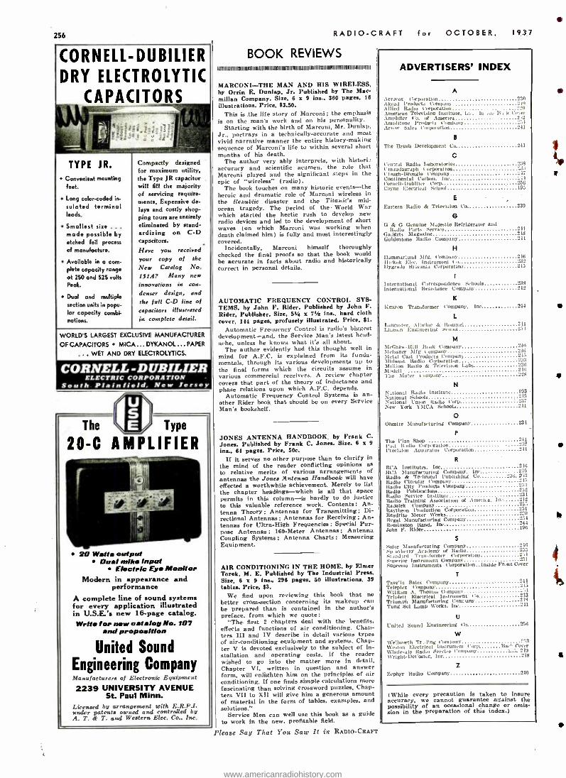
256
CORNELL -DUBILIER DRY ELECTROLYTIC
CAPACITORS
TYPE JR. Convenient mounting feet.
Long color -coded in-
sulated terminal leads.
Smallest size ... mode possible by etched foil process of manufacture.
Available in o com- plete capacity range at 250 and 525 volts Peak,
Dual and multiple section units in popu- lar capacity combi- nations.
Compactly designed for maximum utility, the Type JR capacitor will fill the majority of servicing require- ments. Expensive de- lays and costly shop- ping tours are entirely eliminated by stand- ardizing on C -D capacitors.
Have you received your copy of the New Catalog No. 151A? Many new
innovations in con-
denser design, and the full C -D line of
capacitors illustrated in complete detail.
WORLD'S LARGEST EXCLUSIVE MANUFACTURER
OF CAPACITORS MICA ... DYKANOL ... PAPER
.. WET AND DRY ELECTROLYTICS.
CORNELL -D UBILIER ELECTRIC CORPORATION
South. Plainfield, New Jersey
The \ E Type
20 -C AMPLIFIER
20 Watts output Dual mike input
Electric Eyo Monitor Modern in appearance and
performance A complete line of sound systems for every application illustrated in U.S.E.'s new 16 -page catalog. Write for new catalog No. 107
and proposition
United Sound
Engineering Company Manufacturers of Electronic Equipment
2239 UNIVERSITY AVENUE St. Paul Minn.
Licensed by arrangement with F..R.P.I. under patents owned and controlled by A. T. T. and Western Eire. Co., Inc.
RADIO -CRAFT
BOOK REVIEWS mnhhuuubu69uum9uunuuuuh9numhuu9hu9uuu9uuunnumuun
MARCONI -THE MAN AND HIS WIRELESS, by Orrin E. Dunlap. Jr. Published by The Mar - millan Company. Size, 6 x 9 ins., 360 pages. 16
illustrations. Price, $3.50. This is the life story of Marconi ; the emphasis
is on the man's work and on his personality. Starting with the birth of Marconi, Mr. Dunlap,
Jr., portrays in a technically- accurate and most vivid narrative manner the entire history -making sequence of Marconï s life to within several short months of his death.
The author very ably interprets. with histori accuracy and scientific acumen, the rule that Marconi played and the significant steps in the epic of "wireless" (radio).
The book touches on many historic events -the heroic and dramatic role of Marconi wireless in the Republic disaster and the Titanics mid - ocean tragedy. The period of the World War which started the hectic rush to develop new radio devices and led to the development of short waves (on which Marconi was working when death claimed him) is fully and most interestingly covered.
Incidentally, Marconi himself thoroughly checked the final proofs so that the book would be accurate in facts about radio and historically correct in personal details.
AUTOMATIC FREQUENCY CONTROL SYS- TEMS. by John F. Rider. Published by John F. Rider, Publisher. Size, 51/4 x 71/2 ins., hard cloth cover, 144 pages, profusely illustrated. Price, $1.
Automatic Frequency Control is radio's biggest development -and. the Service Man's latest head- ache, unless he knows what its all about.
The author evidently had this thought well in mind for A.F.C. is explained from its funda- mentals, through its various developments up to the final forms which the circuits assume in various commercial receivers. A review chapter covers that part of the theory of inductance and phase relations upon which A.F.C. depends.
Automatic Frequency Control Systems Ls an- other Rider book that should be on every Service Man's bookshelf.
JONES ANTENNA HANDBOOK. by Frank C. Jones. Published by Frank C. Jones. Size. 6 x 9
ins., 64 pages. Price, 50c.
If it serves no other purpose than to clarify in
the mind of the reader conflicting opinions as to relative merits of various arrangements of antennas the Jones Antenna Handbook will have effected a worthwhile achievement. Merely to list the chapter headings -which is all that space permits in this column -is hardly to do justice to this valuable reference work. Contents: An- tenna Theory : Antennas for Transmitting ; Di- rectional Antennas; Antennas for Receiving; An- tennas for Ultra -High Frequencies: Special Pur- pose Antennas; 160 -Meter Antennas; Antenna Coupling Systems; Antenna Charts ; Measuring Equipment.
for OCTOBER, 1937
AIR CONDITIONING IN THE HOME, by Elmer Torok. M. E. Published by The Industrial Press. Size, 6 x 9 ins., 296 pages, 50 illustrations, 39 tables. Price, $3.
We find upon reviewing this book that no better cross-section concerning its makeup can be prepared than is contained in the author's preface. from which we quote:
"The. first 2 chapters deal with the benefits, effects and functions of air conditioning. Chan- ters III and IV describe in detail various types of air -conditioning equipment and systems. Chap- ter V is devoted exclusively to the subject of in- stallation and operating costs. If the reader wished to go into the matter more in detail. Chapter VI, written in question and answer form, will enlighten him on the principles of air conditioning. If one finds simple calculations more fascinating than solving crossword puzzles. Chap- ters VII to XII will give him a generous amount of material in the form of tables. examples, and solutions."
Service Men can well use this book as a guide to work in the new. profitable field.
Please Say That You Saw It in RADIO -CRAFT
ADVERTISERS' INDEX
A
Arroyo: r1,rp,rati.nl .tkrad Products Corneal* Allied Radio Corporation American Television Institute, I... I.. . . Amplifier Co. of America .tmplitone Produts Company Anew Sales Corporation
B
The Brush Development Co 241
C Central Radio Taboratorie 238 C nnaudagraph Corpnat ion Cla Cluirh- Itrengle Pompa,,' 217 Continental Carbon. Inc Cornell- Dubllier Corp 16 Coyne Electrical School 195
E
Eastern Radio & Television Co. 239
G O & O Genuine Maiestio Refrigerator and
Radio l'art. Service 241 us1gcts Magazine 248 Goldentono Radio Company 241
H Ilammarlund 31ig. ('empara' 246 16..kuk El.r. Instrument I o 232 Ilygrado Sylvania Corporation 245
1
International Correspondence Schools 2238
international Resistance Company "42
K
Kenyon Transformer Company.
L Lancaster, Apwine & lbnnntel I.Wco.n Engìncei ilia Smoot
Inc 244
"41 251
M McGraw -llilt Book Company 240 ]Itisaner Mfg ompans' 246 Metal Cast Products Ceml'any 215 Midwest Radio C,,rporatlun 233 Million Radio & Television labs 236
2216 , M dell 'I he Muter Cump ny 228
N National Radio Institute
193 National Schools National Union Radio t'orp 237 New York YMCA Schools 241
O Ohmite Manufacturing Company 234.
P
The flan Shop 241 Pod. it,dio Corporation 237 Precision Apps atus Corporation 241
R
RCA Instituts. Inc "-48
ItC.t Manufacturing Company. Inc 245 Radio & Technical Publishing Co 236, 2.,3 Radio Circular Company 245 Radio City Posduc s tbmpaU' 253 Radio l'ublicat Ions 252 Itadlo Service Institute 234 Indio Training Association of America. l' 12 Itadolek Company n5 Raytheon Production Corporal:onn 251 Iteadrito Meter Works Regal Manufacturing Company Remington Rand. Inc 844 John F. Rider 196
S Solar Manufacturing Company 240 Sp -ay berry Academy of Radio -
nsand ad Transformer Porlanatpm 214
gprier !mermen( Company 231 Supremo Instruments Corporation.. Inside Front Cover
T
Tavela Sales Company 241 Telepl.z tbmtxuq' 215 William A. Thomas Comparu' i
Triplett Electrical Instrument Cu 213 Triumph Manufacturing Company
241 Tung Sol Lamp Works. Inc
U
United Sound Engineering Co 256
w Wellworth Tr :Ants Compmu' °'t Weston Electrical Instrument Corp Bac" Cover Wholesale Radio Service Company -..a. 219 tVrlght- DeCOstcr. Inc 218
Zephyr Radio Company 2:
240
(While every precaution is taken to insure accuracy, we cannot guarantee against the possibility of an occasional change or omis- sion in the preparation of this index.)
www.americanradiohistory.com
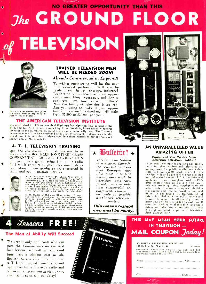
GREATER OPPORTUNITY THAN THIS
LmGR D TELEVISION
Every student receives this giant television cathode ray tube as tart of his equipment.
TRAINED TELEVISION MEN WILL BE NEEDED SOON!
Already Commercial in England! Television engineering will be the next high salaried profession. Will you be ready to cash in with this new industry? Leaders of radio recognized their oppor- tunity some fifteen years ago, and they as engineers have since earned millions! Now the future of television is assured. Are you going to make it your oppor- tunity lt:: success? Trained men will make front S2.500 to 820,000 per year.
THE AMERICAN TELEVISION INSTITUTE was established in 1935, to provide skilled men for television development in the United States. A. T. I. was founded by U. A. Sanabria, internationally famous inventor of the interlaced scanning system, now universally used. The Institute possesses one of the best equipped television experimental laboratories in the world, and it is here that students complete their courses under the personal supervision of Mr. Sanabria.
A. T. I. TELEVISION TRAINING qualifies you (luring the first fees- months tit take your R kl)IO TELEPHONE FIRST GOVER\\1E\ I' LICENSE E\A\ll \ATI( and get into a good paving jolt in the radio field while completing your television instruc- tion. Many of our graduates are successful in radio and sound motion pictures.
M. B. Foster of Prairie Du Chien. Wis., writes: "As a graduate of the class of 1036. I ran highly recommend A. T. I. training with practical equip- ment. Since graduating. I am a technician with the Ampro Motion Picture Corp., making a good salary. I feel secure in knowing that I am able to do nearly anything in sound motion pictures or radio now. and that I am ready for television."
E. D. Carter of Bethany. Ohio. writes: "I spert two years in college and have investigated other training in radio and the allied arts, and 1 have yet to find anything nearly so comprehensive as the A. T. I. training in television, which include.+ all any practical man needs to know about radio. I have earned an average of $2,300 per year since studying with Mr. Sanabria doing television and tele;.hone work."
* uCCetiri ! * 7/17/37. The Nation- al Resources Commit- tee reported to Presi- dent Roosevelt that t h e most important development work in television to a s com- pleted, and that only t h e conlntercial ar- rangements remain to be made to provide n a t i onal television
SV'riire.
This means trained men must be ready.
a
a
The Man of Ability Will Succeed
W... accept only applicants who can pass the examinations on the first four lessons. We will actually send four lessons without cost or ob- ligation, so you may determine how A. T. I. training will benefit you, and equip you for a future in radio and television. Clip coupon at right, now, and mail it to us without delay!
AN UNPARALLELED VALUE AMAZING OFFER
Equipment You Receive From American Television Institute
Is not small, ordinar instruction equipment, but a full sized professional television lab- oratory used for public exhibitions with a steel rack and panels nearly six feet high, two feet wide and eight inches deep mounted on rubber tired casters; R.C.A. amplifier and modulator tubes throughout with A.T.I.'s giant photo -electric cells and î" x 21" cath- ode ray receiving tube, together with all other parts to stake a complete television transmitter and receiver worth a thon -:old dollars to one taking this training. a1I of this i- included with the A.T.I. course and is ours to keep. It is all amazingly low in price nd on terms arranged to suit you. It costs you nothing to thoroughly investigate this opportuuil'. loin cannot afford to pass it up if you want to get in to television. Send Coupon . 'trocs
THIS MAY MEAN YOUR FUTURE
IN TELEVISION - MAIL COUPON Jn n !
AMERICAN TELEVISION INSTITUTE 433 E. Erie St., Chicago. III. RC -1037 Gentlemen: Please send me your free book, and first four lessons, with which I would like to be tested. It is understood that all this is free.
Name Age
Street
t- ty State
www.americanradiohistory.com
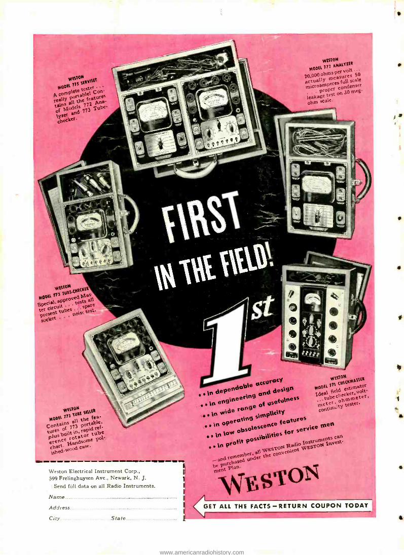
VW"' VIESION
MODEL 77S SERVetE
P. complete test, Con..
really portable. l the feature tains odels
712Tube- ly1M and 773
checker.
wESt0N
MODEL 772 ANALYZER
20.000 ohms P
actually measures full scale 0 .p peL condenser
leakage test on 30 meg
ohm scale.
WEBION ttER
MODEL 773 LURE. CNECMas.
Special, spProv all
r circuit spare tubes noise tes,
socket
wISION
DEL 713 LURE SEMER
Contains of 794131
the abe,
turcs in, rapid
ereneeliandsome F°l. ¡shed ol case
ish ..,c
Weston Electrical Instrument Corp., 599 Frelinghuysen Ave., Newark, N. J.
Send full data on all Radio Instruments.
warne
Address
City State
E' dependable d de ign
in engineering usefulness
in wide ronge
of
simplicity in
operatingésence {eptures
possibilities for sere w obsolescence .. in low can
in profit P
Ra Insu
oN Invest .. d WEST
and remember, purchased
eSC óNenient
Purchase pla +,.
OS ment ST
W ESION
MODEL 771 CNECRMASIER
Ideal field estimator tube checker lt-
continuity tester.
GET ALL THE FACTS- RETURN COUPON TODAY
I
a
www.americanradiohistory.com
Related Documents