CTI Products RadioPro™ IP Gateway Installation Guide for Kenwood NEXEDGE NX-57xx/58xx Radios Document # S2-61905-823 For Version 8 Software

Welcome message from author
This document is posted to help you gain knowledge. Please leave a comment to let me know what you think about it! Share it to your friends and learn new things together.
Transcript
CTI Products
RadioPro™ IP Gateway Installation Guide
for
Kenwood NEXEDGE NX-57xx/58xx Radios
Document # S2-61905-823 For Version 8 Software
RadioPro IP Gateway Installation and Configuration Guide NEXEDGE NX-7xx/8xx
Contact Us
Support, replacement part ordering, and service may be arranged by contacting our Cincinnati office. Parts for service can be returned following a request of a Return Material Authorization.
CTI Products, Inc. 1211 W Sharon Rd Cincinnati, OH 45240
513-595-5900
Disclaimer
Information in this document is provided with best efforts for completeness and accuracy. However, no guarantee is expressed or implied, and details may change without notice.
Fonts used in this document:
Technical terms
Cross-references within this document
Hyperlinks to other documents or web pages
Warnings
Software menus, menu options, folders, pages, and parameters Software parameter values
RadioPro IP Gateway Installation and Configuration Guide NEXEDGE NX-57xx/58xx
3
Contents 1 SYSTEM OVERVIEW .......................................................................................................................................................... 4
1.1 System Components .................................................................................................................................................. 4 1.2 Architecture .............................................................................................................................................................. 6 1.3 Environmental Considerations ................................................................................................................................... 7 1.4 RadioPro Version Match ........................................................................................................................................... 7 1.5 Static IP Address ....................................................................................................................................................... 8 1.6 Accessing the RadioPro IP Gateway using Port Forwarding ....................................................................................... 8 1.7 Licensing .................................................................................................................................................................. 8
2. WHAT IS INCLUDED ......................................................................................................................................................... 9 2.1 RadioPro IP Gateway Kit .......................................................................................................................................... 9
3. OTHER ITEMS NEEDED ................................................................................................................................................... 10 3.1 Radio Interface Cable .............................................................................................................................................. 10 3.2 Control Station Radio .............................................................................................................................................. 10 3.3 Radio Programming Cable ....................................................................................................................................... 10 3.5 Laptop or PC ........................................................................................................................................................... 10
4. CONFIGURATION AND INSTALLATION STEPS: OUTLINE .................................................................................................... 11 Step 1a. for NEXEDGE NX-57xx/58xx: Configure Voice Control Station Radio(s) using Kenwood FPU ...................... 12 Step 1b. for NEXEDGE NX-57xx/58xx: Configure Data Revert Control Station Radio(s) using Kenwood FPU ............. 19 Step 1d. for NEXEDGE NX-57xx/58xx: Configure Subscriber Radios using the Kenwood FPU Software...................... 20 Step 2. for NEXEDGE NX-57xx/58xx: Connect RadioPro IP Gateway to Control Station Radio .................................... 26 Step 3. Configure RadioPro IP Gateway ........................................................................................................................ 27 Step 4. Connect RadioPro IP Gateway to IP Network .................................................................................................... 32 Step 5. Configure Port Forwarding on Firewall Device .................................................................................................. 33 Step 6. Install and Configure RadioPro Clients/Apps ..................................................................................................... 34
5. RADIOPRO IP GATEWAY OPERATION ............................................................................................................................. 35 5.1 Power-up................................................................................................................................................................. 35 5.2 Indicators ................................................................................................................................................................ 35
6. APPENDIX ...................................................................................................................................................................... 36 6.1 Appendix - RadioPro IP Gateway Specifications ...................................................................................................... 36 6.2 Appendix - IP Addressing........................................................................................................................................ 36 6.3 Appendix - Rack Mounting ..................................................................................................................................... 37 6.4 Appendix - System Compatibility Considerations .................................................................................................... 37 6.5 Appendix - Installing a Time Server ........................................................................................................................ 38 6.7 Appendix - Radio Interface Cables – NEXEDGE NX700/800/5700/5800 ................................................................. 40 6.7 Appendix - Converting a Timed-license to Non-expiring .......................................................................................... 41
7. INDEX ........................................................................................................................................................................... 42 8. SYSTEM PLANNER TEMPLATE PAGE 1 OF 2 .................................................................................................................. 44 SYSTEM PLANNER TEMPLATE PAGE 2 OF 2 ...................................................................................................................... 45
RadioPro IP Gateway Installation and Configuration Guide NEXEDGE NX-57xx/58xx
4
1 SYSTEM OVERVIEW RadioPro™ provides remote access to 2-way radios via IP Networks. This “Dispatch over IP” (DoIP) solution consists of PC-based software allowing voice and data communications between PC users and 2-way radio subscribers. Communications with radio subscribers is also possible for remote mobile users using Android or iOS devices. A RadioPro system consists of at least one RadioPro IP Gateway (server) and at least one client (Dispatch™, Solo™, Talk™, or Talk for Mobile™) with an IP network connecting the RadioPro components.
1.1 System Components CTI’s Dispatch over IP system is based on Server-Client architecture. System components are described below:
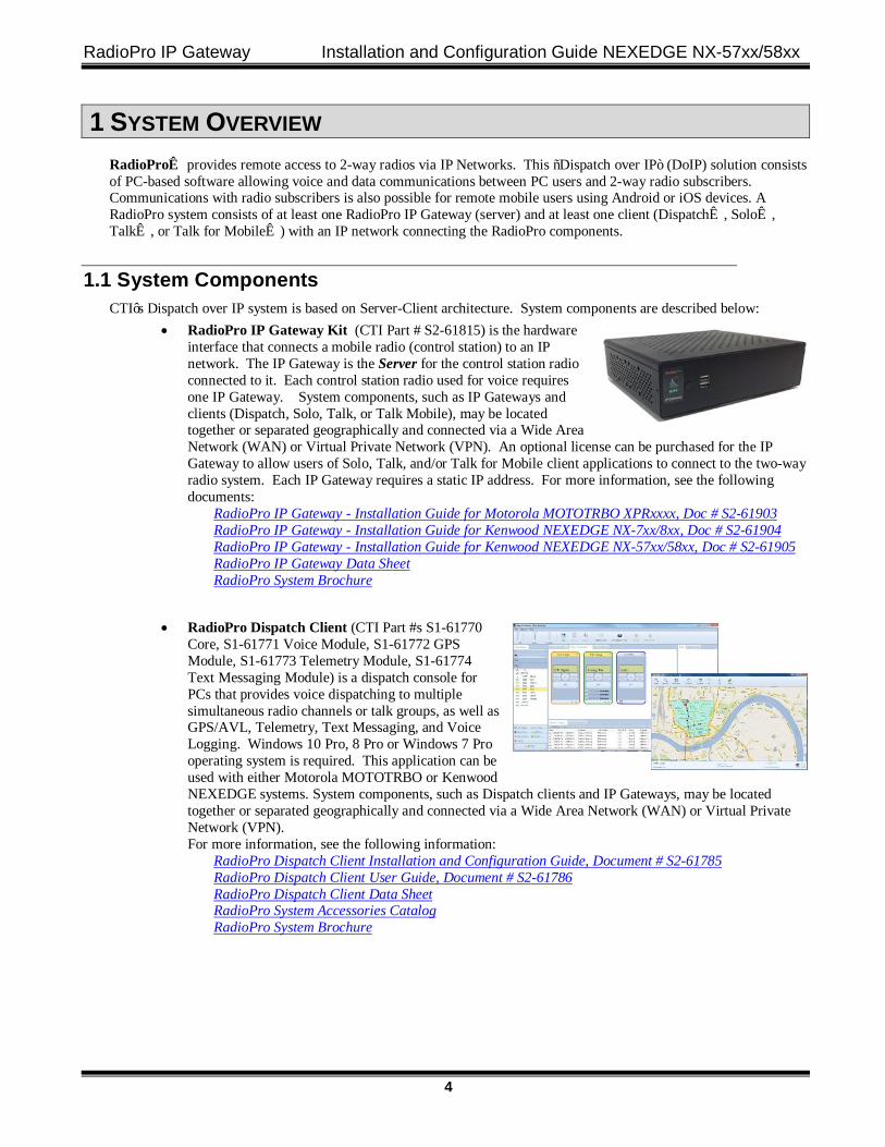
• RadioPro IP Gateway Kit (CTI Part # S2-61815) is the hardware interface that connects a mobile radio (control station) to an IP network. The IP Gateway is the Server for the control station radio connected to it. Each control station radio used for voice requires one IP Gateway. System components, such as IP Gateways and clients (Dispatch, Solo, Talk, or Talk Mobile), may be located together or separated geographically and connected via a Wide Area Network (WAN) or Virtual Private Network (VPN). An optional license can be purchased for the IP Gateway to allow users of Solo, Talk, and/or Talk for Mobile client applications to connect to the two-way radio system. Each IP Gateway requires a static IP address. For more information, see the following documents:
RadioPro IP Gateway - Installation Guide for Motorola MOTOTRBO XPRxxxx, Doc # S2-61903 RadioPro IP Gateway - Installation Guide for Kenwood NEXEDGE NX-7xx/8xx, Doc # S2-61904 RadioPro IP Gateway - Installation Guide for Kenwood NEXEDGE NX-57xx/58xx, Doc # S2-61905 RadioPro IP Gateway Data Sheet RadioPro System Brochure
• RadioPro Dispatch Client (CTI Part #s S1-61770
Core, S1-61771 Voice Module, S1-61772 GPS Module, S1-61773 Telemetry Module, S1-61774 Text Messaging Module) is a dispatch console for PCs that provides voice dispatching to multiple simultaneous radio channels or talk groups, as well as GPS/AVL, Telemetry, Text Messaging, and Voice Logging. Windows 10 Pro, 8 Pro or Windows 7 Pro operating system is required. This application can be used with either Motorola MOTOTRBO or Kenwood NEXEDGE systems. System components, such as Dispatch clients and IP Gateways, may be located together or separated geographically and connected via a Wide Area Network (WAN) or Virtual Private Network (VPN). For more information, see the following information:
RadioPro Dispatch Client Installation and Configuration Guide, Document # S2-61785 RadioPro Dispatch Client User Guide, Document # S2-61786 RadioPro Dispatch Client Data Sheet RadioPro System Accessories Catalog RadioPro System Brochure
RadioPro IP Gateway Installation and Configuration Guide NEXEDGE NX-57xx/58xx
5
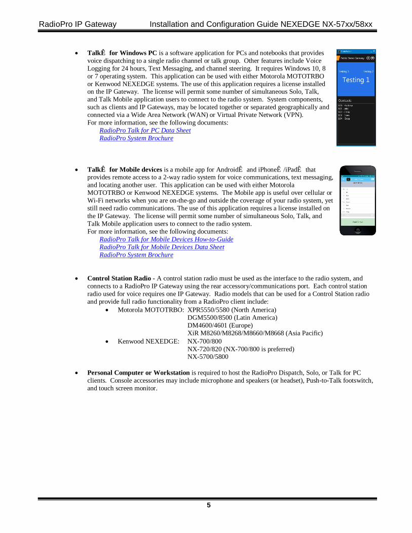
• Talk™ for Windows PC is a software application for PCs and notebooks that provides voice dispatching to a single radio channel or talk group. Other features include Voice Logging for 24 hours, Text Messaging, and channel steering. It requires Windows 10, 8 or 7 operating system. This application can be used with either Motorola MOTOTRBO or Kenwood NEXEDGE systems. The use of this application requires a license installed on the IP Gateway. The license will permit some number of simultaneous Solo, Talk, and Talk Mobile application users to connect to the radio system. System components, such as clients and IP Gateways, may be located together or separated geographically and connected via a Wide Area Network (WAN) or Virtual Private Network (VPN). For more information, see the following documents:
RadioPro Talk for PC Data Sheet RadioPro System Brochure
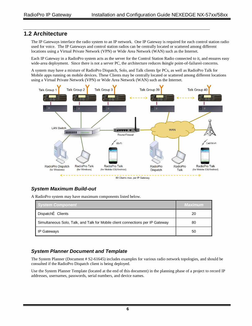
• Talk™ for Mobile devices is a mobile app for Android™ and iPhone™/iPad™ that provides remote access to a 2-way radio system for voice communications, text messaging, and locating another user. This application can be used with either Motorola MOTOTRBO or Kenwood NEXEDGE systems. The Mobile app is useful over cellular or Wi-Fi networks when you are on-the-go and outside the coverage of your radio system, yet still need radio communications. The use of this application requires a license installed on the IP Gateway. The license will permit some number of simultaneous Solo, Talk, and Talk Mobile application users to connect to the radio system. For more information, see the following documents:
RadioPro Talk for Mobile Devices How-to-Guide RadioPro Talk for Mobile Devices Data Sheet RadioPro System Brochure
• Control Station Radio - A control station radio must be used as the interface to the radio system, and
connects to a RadioPro IP Gateway using the rear accessory/communications port. Each control station radio used for voice requires one IP Gateway. Radio models that can be used for a Control Station radio and provide full radio functionality from a RadioPro client include:
• Motorola MOTOTRBO: XPR5550/5580 (North America) DGM5500/8500 (Latin America) DM4600/4601 (Europe) XiR M8260/M8268/M8660/M8668 (Asia Pacific)
• Kenwood NEXEDGE: NX-700/800 NX-720/820 (NX-700/800 is preferred) NX-5700/5800
• Personal Computer or Workstation is required to host the RadioPro Dispatch, Solo, or Talk for PC
clients. Console accessories may include microphone and speakers (or headset), Push-to-Talk footswitch, and touch screen monitor.
RadioPro IP Gateway Installation and Configuration Guide NEXEDGE NX-57xx/58xx
6
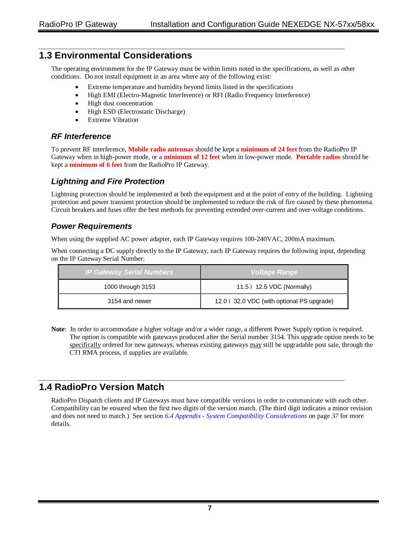
1.2 Architecture The IP Gateways interface the radio system to an IP network. One IP Gateway is required for each control station radio used for voice. The IP Gateways and control station radios can be centrally located or scattered among different locations using a Virtual Private Network (VPN) or Wide Area Network (WAN) such as the Internet.
Each IP Gateway in a RadioPro system acts as the server for the Control Station Radio connected to it, and ensures easy wide-area deployment. Since there is not a server PC, the architecture reduces “single point-of-failure” concerns.
A system may have a mixture of RadioPro Dispatch, Solo, and Talk clients fpr PCs, as well as RadioPro Talk for Mobile apps running on mobile devices. These Clients may be centrally located or scattered among different locations using a Virtual Private Network (VPN) or Wide Area Network (WAN) such as the Internet.
System Maximum Build-out A RadioPro system may have maximum components listed below.
System Component Maximum
Dispatch™ Clients 20
Simultaneous Solo, Talk, and Talk for Mobile client connections per IP Gateway 80
IP Gateways 50
System Planner Document and Template The System Planner (Document # S2-61645) includes examples for various radio network topologies, and should be consulted if the RadioPro Dispatch client is being deployed.
Use the System Planner Template (located at the end of this document) in the planning phase of a project to record IP addresses, usernames, passwords, serial numbers, and device names.
RadioPro IP Gateway Installation and Configuration Guide NEXEDGE NX-57xx/58xx
7
1.3 Environmental Considerations The operating environment for the IP Gateway must be within limits noted in the specifications, as well as other conditions. Do not install equipment in an area where any of the following exist:
• Extreme temperature and humidity beyond limits listed in the specifications • High EMI (Electro-Magnetic Interference) or RFI (Radio Frequency Interference) • High dust concentration • High ESD (Electrostatic Discharge) • Extreme Vibration
RF Interference To prevent RF interference, Mobile radio antennas should be kept a minimum of 24 feet from the RadioPro IP Gateway when in high-power mode, or a minimum of 12 feet when in low-power mode. Portable radios should be kept a minimum of 6 feet from the RadioPro IP Gateway.
Lightning and Fire Protection Lightning protection should be implemented at both the equipment and at the point of entry of the building. Lightning protection and power transient protection should be implemented to reduce the risk of fire caused by these phenomena. Circuit breakers and fuses offer the best methods for preventing extended over-current and over-voltage conditions.
Power Requirements When using the supplied AC power adapter, each IP Gateway requires 100-240VAC, 200mA maximum.
When connecting a DC supply directly to the IP Gateway, each IP Gateway requires the following input, depending on the IP Gateway Serial Number:
IP Gateway Serial Numbers Voltage Range
1000 through 3153 11.5 – 12.5 VDC (Normally)
3154 and newer 12.0 – 32.0 VDC (with optional PS upgrade)
Note: In order to accommodate a higher voltage and/or a wider range, a different Power Supply option is required. The option is compatible with gateways produced after the Serial number 3154. This upgrade option needs to be specifically ordered for new gateways, whereas existing gateways may still be upgradable post sale, through the CTI RMA process, if supplies are available.
1.4 RadioPro Version Match RadioPro Dispatch clients and IP Gateways must have compatible versions in order to communicate with each other. Compatibility can be ensured when the first two digits of the version match. (The third digit indicates a minor revision and does not need to match.) See section 6.4 Appendix - System Compatibility Considerations on page 37 for more details.
RadioPro IP Gateway Installation and Configuration Guide NEXEDGE NX-57xx/58xx
8
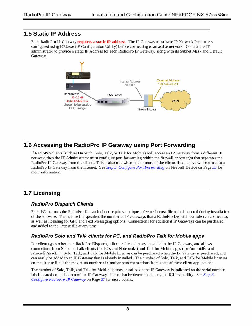
1.5 Static IP Address Each RadioPro IP Gateway requires a static IP address. The IP Gateway must have IP Network Parameters configured using ICU.exe (IP Configuration Utility) before connecting to an active network. Contact the IT administrator to provide a static IP Address for each RadioPro IP Gateway, along with its Subnet Mask and Default Gateway.
1.6 Accessing the RadioPro IP Gateway using Port Forwarding If RadioPro clients (such as Dispatch, Solo, Talk, or Talk for Mobile) will access an IP Gateway from a different IP network, then the IT Administrator must configure port forwarding within the firewall or router(s) that separates the RadioPro IP Gateway from the clients. This is also true when one or more of the clients listed above will connect to a RadioPro IP Gateway from the Internet. See Step 5. Configure Port Forwarding on Firewall Device on Page 33 for more information.
1.7 Licensing
RadioPro Dispatch Clients Each PC that runs the RadioPro Dispatch client requires a unique software license file to be imported during installation of the software. The license file specifies the number of IP Gateways that a RadioPro Dispatch console can connect to, as well as licensing for GPS and Text Messaging options. Connections for additional IP Gateways can be purchased and added to the license file at any time.
RadioPro Solo and Talk clients for PC, and RadioPro Talk for Mobile apps For client types other than RadioPro Dispatch, a license file is factory-installed in the IP Gateway, and allows connections from Solo and Talk clients (for PCs and Notebooks) and Talk for Mobile apps (for Android™ and iPhone™/iPad™). Solo, Talk, and Talk for Mobile licenses can be purchased when the IP Gateway is purchased, and can easily be added to an IP Gateway that is already installed. The number of Solo, Talk, and Talk for Mobile licenses on the license file is the maximum number of simultaneous connections from users of these client applications.
The number of Solo, Talk, and Talk for Mobile licenses installed on the IP Gateway is indicated on the serial number label located on the bottom of the IP Gateway. It can also be determined using the ICU.exe utility. See Step 3. Configure RadioPro IP Gateway on Page 27 for more details.
RadioPro IP Gateway Installation and Configuration Guide NEXEDGE NX-57xx/58xx
9
2. WHAT IS INCLUDED
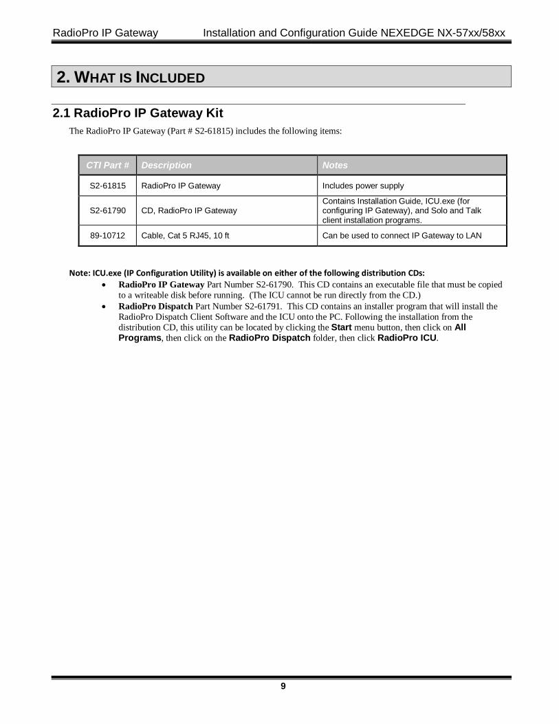
2.1 RadioPro IP Gateway Kit The RadioPro IP Gateway (Part # S2-61815) includes the following items:
CTI Part # Description Notes
S2-61815 RadioPro IP Gateway Includes power supply
S2-61790 CD, RadioPro IP Gateway Contains Installation Guide, ICU.exe (for configuring IP Gateway), and Solo and Talk client installation programs.
89-10712 Cable, Cat 5 RJ45, 10 ft Can be used to connect IP Gateway to LAN
Note: ICU.exe (IP Configuration Utility) is available on either of the following distribution CDs: • RadioPro IP Gateway Part Number S2-61790. This CD contains an executable file that must be copied
to a writeable disk before running. (The ICU cannot be run directly from the CD.) • RadioPro Dispatch Part Number S2-61791. This CD contains an installer program that will install the
RadioPro Dispatch Client Software and the ICU onto the PC. Following the installation from the distribution CD, this utility can be located by clicking the Start menu button, then click on All Programs, then click on the RadioPro Dispatch folder, then click RadioPro ICU.
RadioPro IP Gateway Installation and Configuration Guide NEXEDGE NX-57xx/58xx
10
3. OTHER ITEMS NEEDED
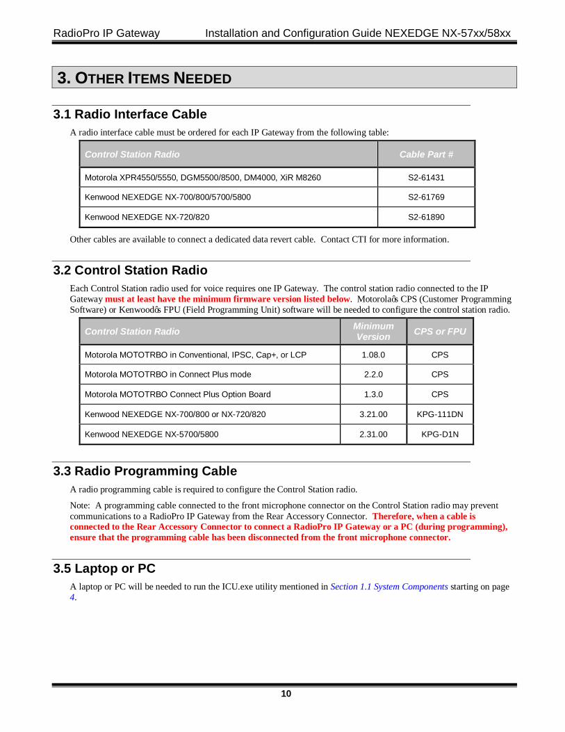
3.1 Radio Interface Cable A radio interface cable must be ordered for each IP Gateway from the following table:
Control Station Radio Cable Part #
Motorola XPR4550/5550, DGM5500/8500, DM4000, XiR M8260 S2-61431
Kenwood NEXEDGE NX-700/800/5700/5800 S2-61769
Kenwood NEXEDGE NX-720/820 S2-61890
Other cables are available to connect a dedicated data revert cable. Contact CTI for more information.
3.2 Control Station Radio Each Control Station radio used for voice requires one IP Gateway. The control station radio connected to the IP Gateway must at least have the minimum firmware version listed below. Motorola’s CPS (Customer Programming Software) or Kenwood’s FPU (Field Programming Unit) software will be needed to configure the control station radio.
Control Station Radio Minimum Version CPS or FPU
Motorola MOTOTRBO in Conventional, IPSC, Cap+, or LCP 1.08.0 CPS
Motorola MOTOTRBO in Connect Plus mode 2.2.0 CPS
Motorola MOTOTRBO Connect Plus Option Board 1.3.0 CPS
Kenwood NEXEDGE NX-700/800 or NX-720/820 3.21.00 KPG-111DN
Kenwood NEXEDGE NX-5700/5800 2.31.00 KPG-D1N
3.3 Radio Programming Cable A radio programming cable is required to configure the Control Station radio.
Note: A programming cable connected to the front microphone connector on the Control Station radio may prevent communications to a RadioPro IP Gateway from the Rear Accessory Connector. Therefore, when a cable is connected to the Rear Accessory Connector to connect a RadioPro IP Gateway or a PC (during programming), ensure that the programming cable has been disconnected from the front microphone connector.
3.5 Laptop or PC A laptop or PC will be needed to run the ICU.exe utility mentioned in Section 1.1 System Components starting on page 4.
RadioPro IP Gateway Installation and Configuration Guide NEXEDGE NX-57xx/58xx
11
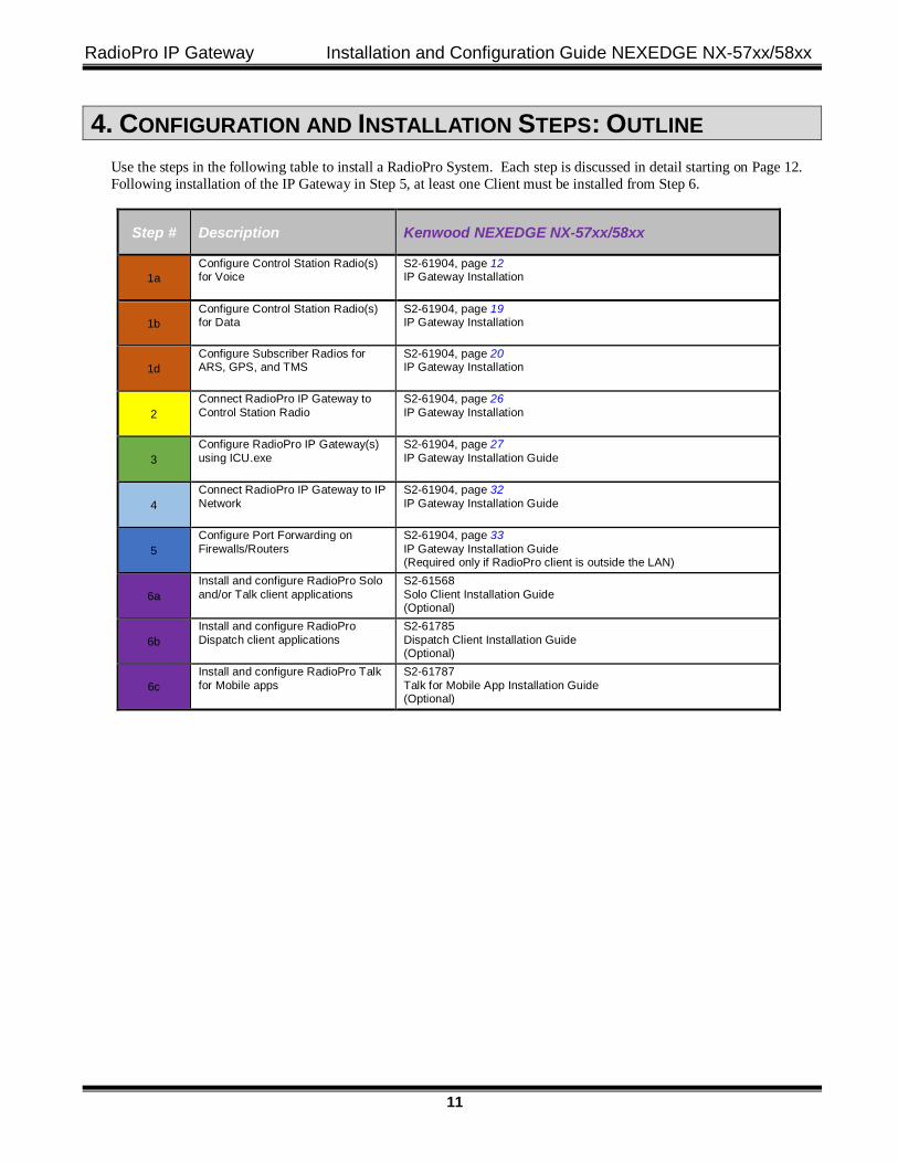
4. CONFIGURATION AND INSTALLATION STEPS: OUTLINE Use the steps in the following table to install a RadioPro System. Each step is discussed in detail starting on Page 12. Following installation of the IP Gateway in Step 5, at least one Client must be installed from Step 6.
Step # Description Kenwood NEXEDGE NX-57xx/58xx
1a Configure Control Station Radio(s) for Voice
S2-61904, page 12 IP Gateway Installation
1b Configure Control Station Radio(s) for Data
S2-61904, page 19 IP Gateway Installation
1d Configure Subscriber Radios for ARS, GPS, and TMS
S2-61904, page 20 IP Gateway Installation
2 Connect RadioPro IP Gateway to Control Station Radio
S2-61904, page 26 IP Gateway Installation
3 Configure RadioPro IP Gateway(s) using ICU.exe
S2-61904, page 27 IP Gateway Installation Guide
4 Connect RadioPro IP Gateway to IP Network
S2-61904, page 32 IP Gateway Installation Guide
5 Configure Port Forwarding on Firewalls/Routers
S2-61904, page 33 IP Gateway Installation Guide (Required only if RadioPro client is outside the LAN)
6a Install and configure RadioPro Solo and/or Talk client applications
S2-61568 Solo Client Installation Guide (Optional)
6b Install and configure RadioPro Dispatch client applications
S2-61785 Dispatch Client Installation Guide (Optional)
6c Install and configure RadioPro Talk for Mobile apps
S2-61787 Talk for Mobile App Installation Guide (Optional)
RadioPro IP Gateway Installation and Configuration Guide NEXEDGE NX-57xx/58xx
12
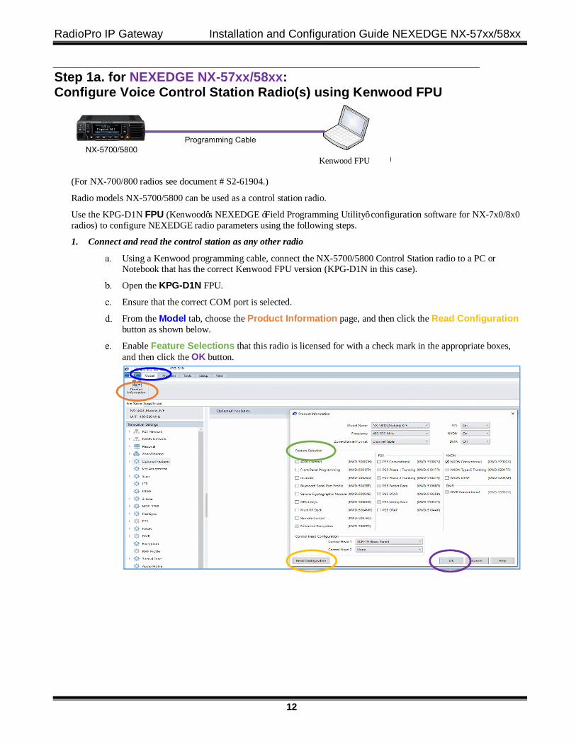
Step 1a. for NEXEDGE NX-57xx/58xx: Configure Voice Control Station Radio(s) using Kenwood FPU
(For NX-700/800 radios see document # S2-61904.)
Radio models NX-5700/5800 can be used as a control station radio.
Use the KPG-D1N FPU (Kenwood’s NEXEDGE ‘Field Programming Utility’ configuration software for NX-7x0/8x0 radios) to configure NEXEDGE radio parameters using the following steps.
1. Connect and read the control station as any other radio
Using a Kenwood programming cable, connect the NX-5700/5800 Control Station radio to a PC or Notebook that has the correct Kenwood FPU version (KPG-D1N in this case).
Open the KPG-D1N FPU.
Ensure that the correct COM port is selected.
From the Model tab, choose the Product Information page, and then click the Read Configuration button as shown below.
Enable Feature Selections that this radio is licensed for with a check mark in the appropriate boxes, and then click the OK button.
Kenwood FPU
RadioPro IP Gateway Installation and Configuration Guide NEXEDGE NX-57xx/58xx
13
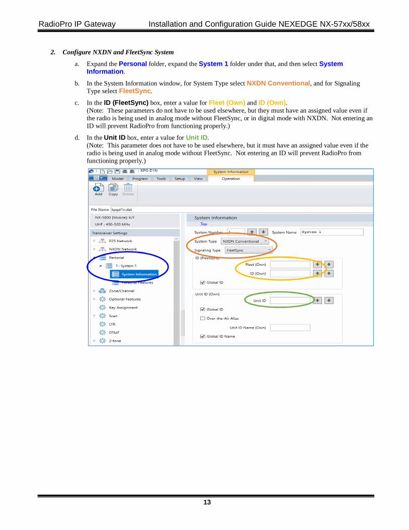
2. Configure NXDN and FleetSync System
a. Expand the Personal folder, expand the System 1 folder under that, and then select System Information.
b. In the System Information window, for System Type select NXDN Conventional, and for Signaling Type select FleetSync.
c. In the ID (FleetSync) box, enter a value for Fleet (Own) and ID (Own). (Note: These parameters do not have to be used elsewhere, but they must have an assigned value even if the radio is being used in analog mode without FleetSync, or in digital mode with NXDN. Not entering an ID will prevent RadioPro from functioning properly.)
d. In the Unit ID box, enter a value for Unit ID. (Note: This parameter does not have to be used elsewhere, but it must have an assigned value even if the radio is being used in analog mode without FleetSync. Not entering an ID will prevent RadioPro from functioning properly.)
RadioPro IP Gateway Installation and Configuration Guide NEXEDGE NX-57xx/58xx
14
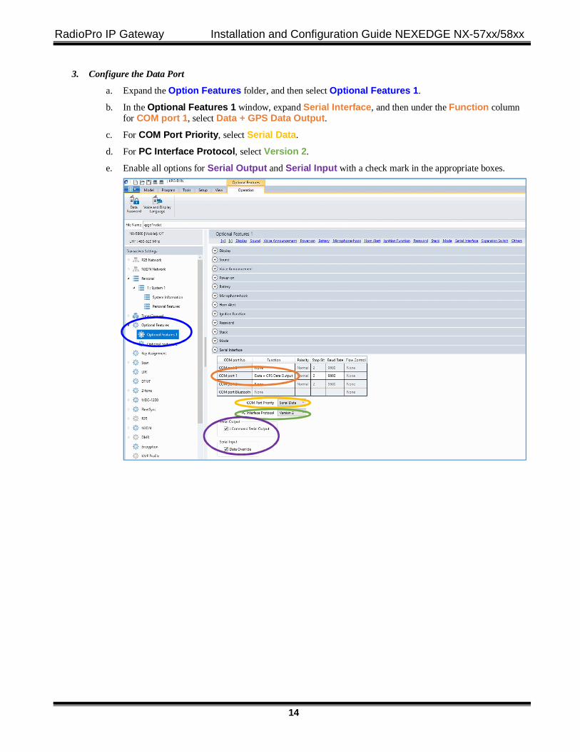
3. Configure the Data Port
a. Expand the Option Features folder, and then select Optional Features 1.
b. In the Optional Features 1 window, expand Serial Interface, and then under the Function column for COM port 1, select Data + GPS Data Output.
c. For COM Port Priority, select Serial Data.
d. For PC Interface Protocol, select Version 2.
e. Enable all options for Serial Output and Serial Input with a check mark in the appropriate boxes.
RadioPro IP Gateway Installation and Configuration Guide NEXEDGE NX-57xx/58xx
15
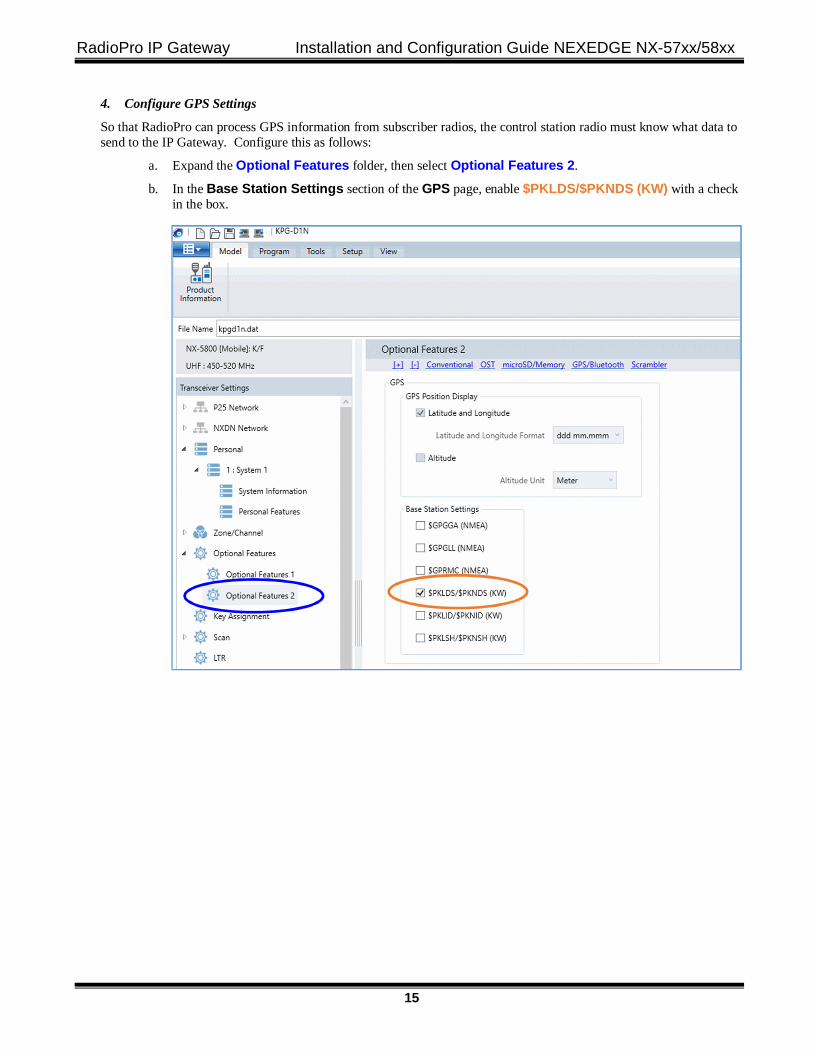
4. Configure GPS Settings
So that RadioPro can process GPS information from subscriber radios, the control station radio must know what data to send to the IP Gateway. Configure this as follows:
a. Expand the Optional Features folder, then select Optional Features 2.
b. In the Base Station Settings section of the GPS page, enable $PKLDS/$PKNDS (KW) with a check in the box.
RadioPro IP Gateway Installation and Configuration Guide NEXEDGE NX-57xx/58xx
16
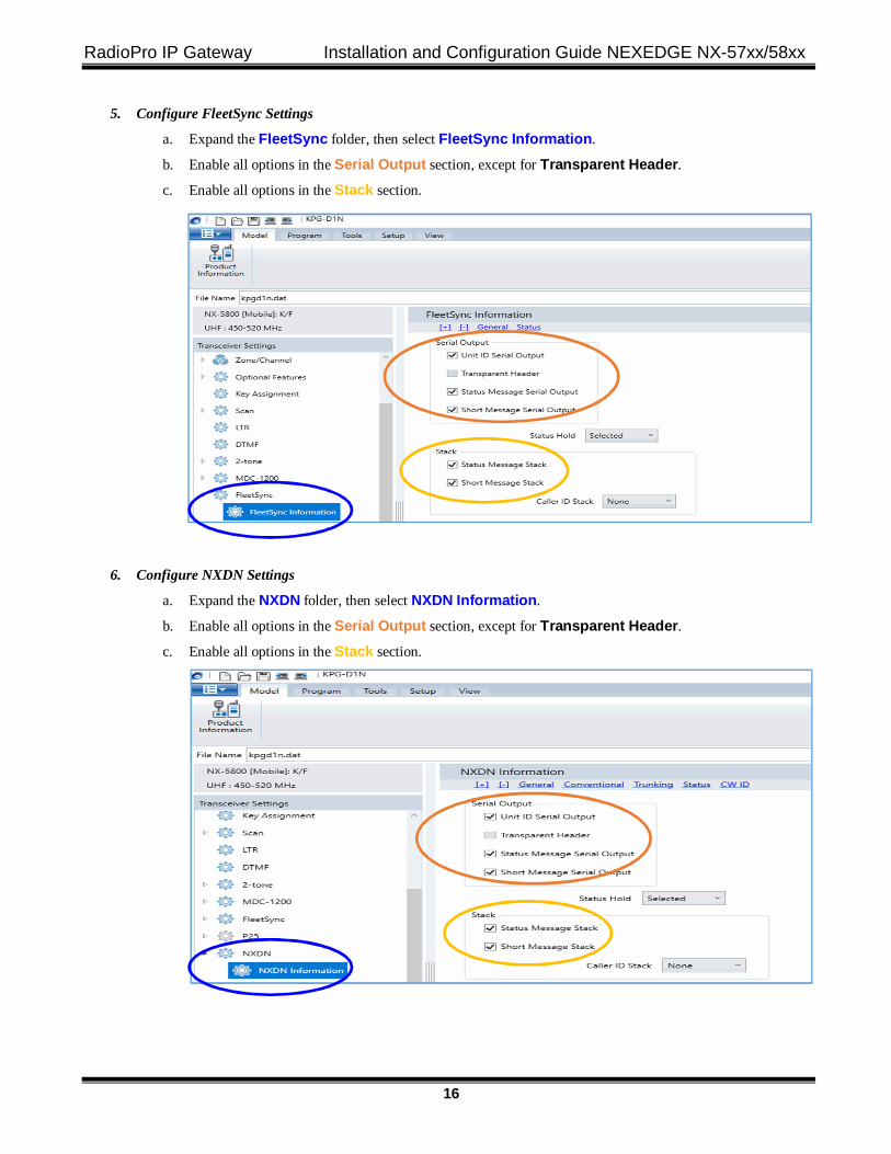
5. Configure FleetSync Settings
a. Expand the FleetSync folder, then select FleetSync Information.
b. Enable all options in the Serial Output section, except for Transparent Header. c. Enable all options in the Stack section.
6. Configure NXDN Settings
a. Expand the NXDN folder, then select NXDN Information.
b. Enable all options in the Serial Output section, except for Transparent Header. c. Enable all options in the Stack section.
RadioPro IP Gateway Installation and Configuration Guide NEXEDGE NX-57xx/58xx
17
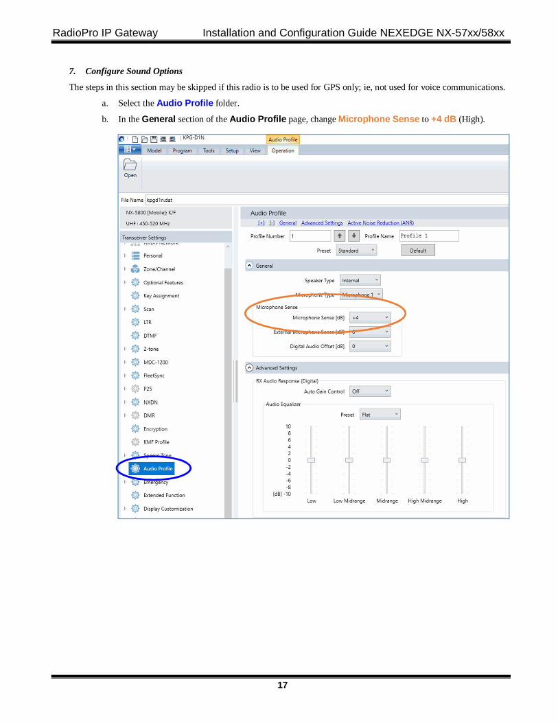
7. Configure Sound Options
The steps in this section may be skipped if this radio is to be used for GPS only; ie, not used for voice communications.
a. Select the Audio Profile folder.
b. In the General section of the Audio Profile page, change Microphone Sense to +4 dB (High).
RadioPro IP Gateway Installation and Configuration Guide NEXEDGE NX-57xx/58xx
18
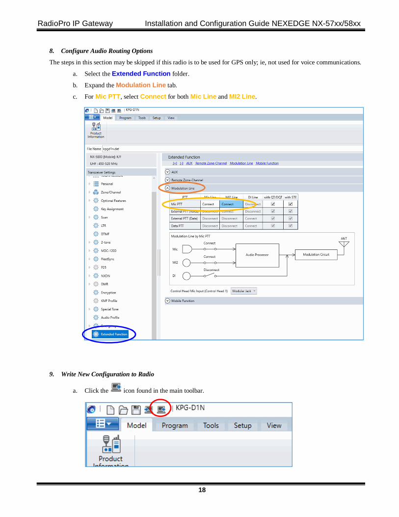
8. Configure Audio Routing Options
The steps in this section may be skipped if this radio is to be used for GPS only; ie, not used for voice communications.
a. Select the Extended Function folder.
b. Expand the Modulation Line tab.
c. For Mic PTT, select Connect for both Mic Line and MI2 Line.
9. Write New Configuration to Radio
a. Click the icon found in the main toolbar.
RadioPro IP Gateway Installation and Configuration Guide NEXEDGE NX-57xx/58xx
19
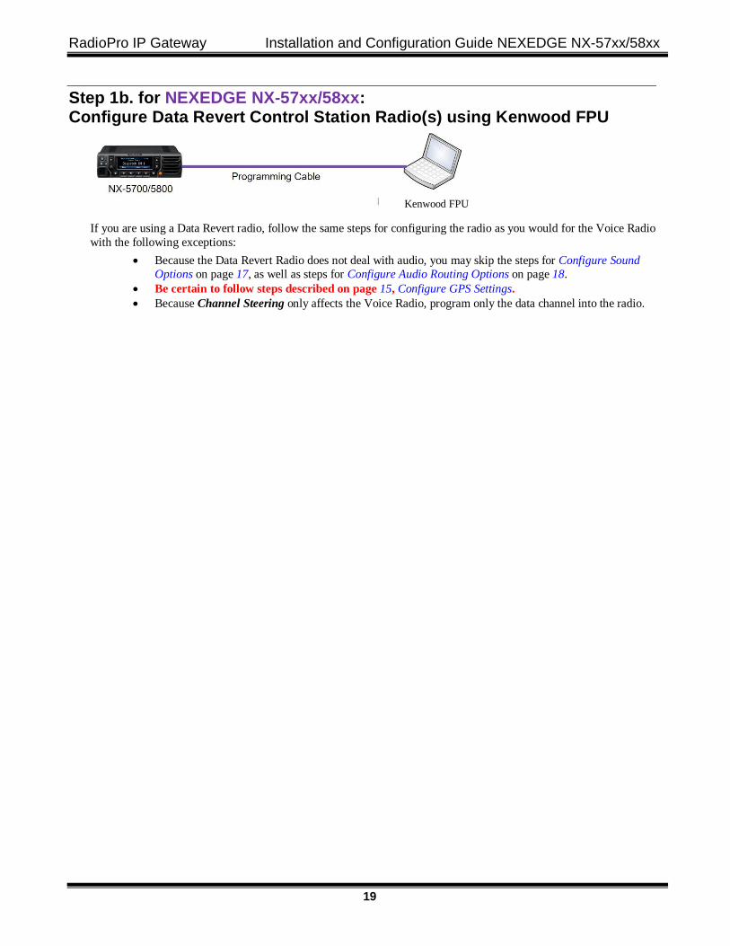
Step 1b. for NEXEDGE NX-57xx/58xx: Configure Data Revert Control Station Radio(s) using Kenwood FPU
If you are using a Data Revert radio, follow the same steps for configuring the radio as you would for the Voice Radio with the following exceptions:
• Because the Data Revert Radio does not deal with audio, you may skip the steps for Configure Sound Options on page 17, as well as steps for Configure Audio Routing Options on page 18.
• Be certain to follow steps described on page 15, Configure GPS Settings. • Because Channel Steering only affects the Voice Radio, program only the data channel into the radio.
Kenwood FPU
RadioPro IP Gateway Installation and Configuration Guide NEXEDGE NX-57xx/58xx
20
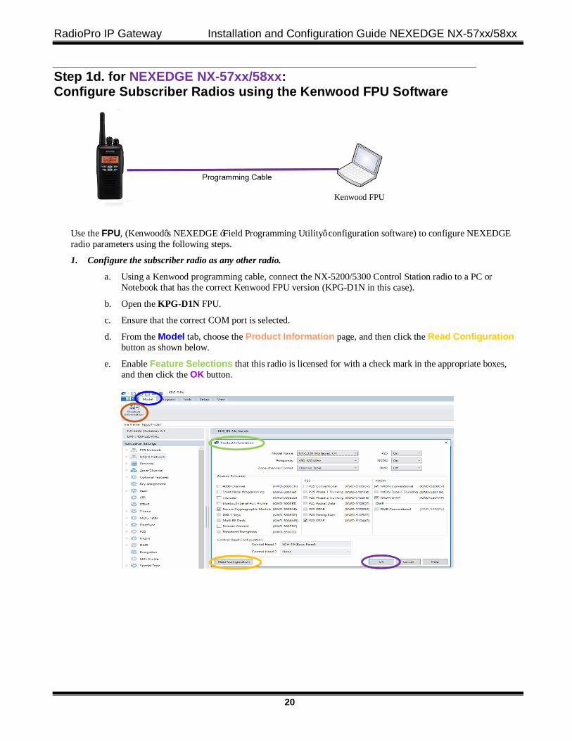
Step 1d. for NEXEDGE NX-57xx/58xx: Configure Subscriber Radios using the Kenwood FPU Software
Use the FPU, (Kenwood’s NEXEDGE ‘Field Programming Utility’ configuration software) to configure NEXEDGE radio parameters using the following steps.
1. Configure the subscriber radio as any other radio.
a. Using a Kenwood programming cable, connect the NX-5200/5300 Control Station radio to a PC or Notebook that has the correct Kenwood FPU version (KPG-D1N in this case).
b. Open the KPG-D1N FPU.
c. Ensure that the correct COM port is selected.
d. From the Model tab, choose the Product Information page, and then click the Read Configuration button as shown below.
e. Enable Feature Selections that this radio is licensed for with a check mark in the appropriate boxes, and then click the OK button.
Kenwood FPU
RadioPro IP Gateway Installation and Configuration Guide NEXEDGE NX-57xx/58xx
21
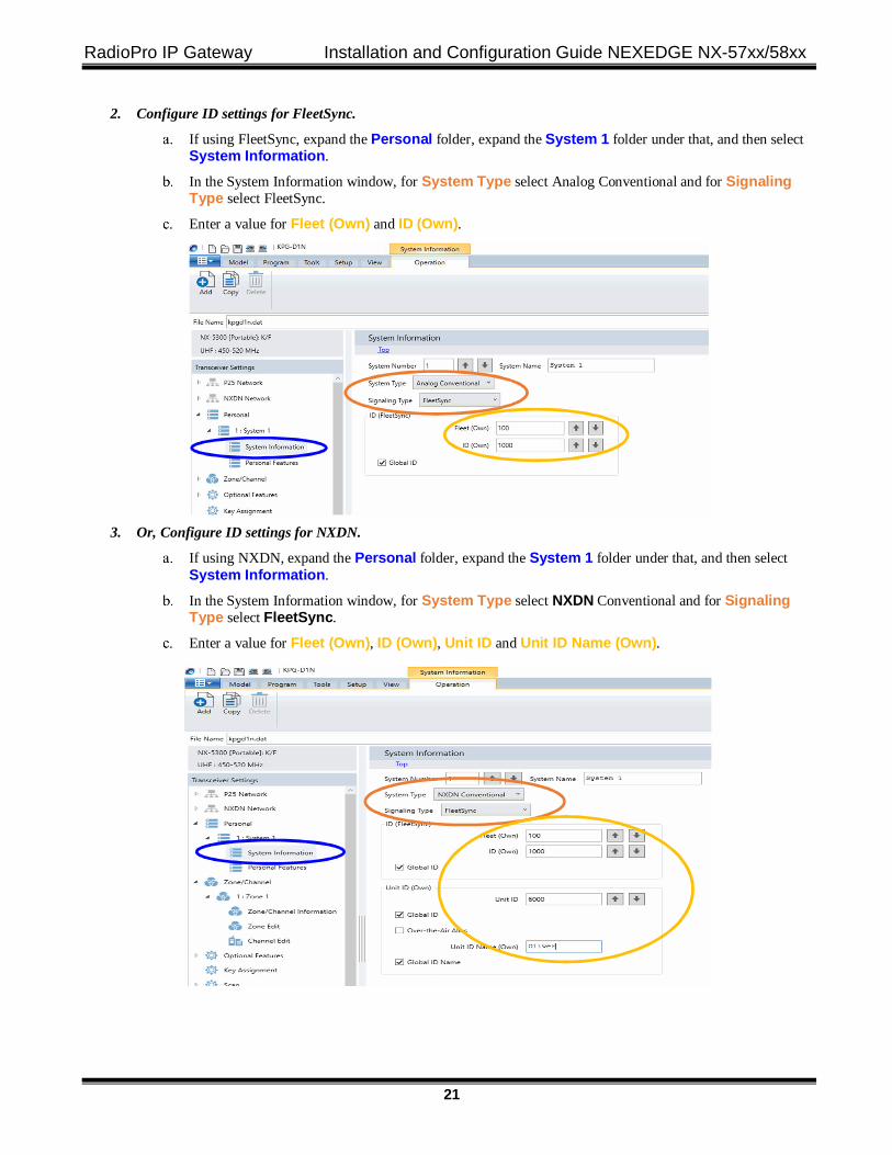
2. Configure ID settings for FleetSync.
If using FleetSync, expand the Personal folder, expand the System 1 folder under that, and then select System Information.
In the System Information window, for System Type select Analog Conventional and for Signaling Type select FleetSync.
Enter a value for Fleet (Own) and ID (Own).
3. Or, Configure ID settings for NXDN.
If using NXDN, expand the Personal folder, expand the System 1 folder under that, and then select System Information.
In the System Information window, for System Type select NXDN Conventional and for Signaling Type select FleetSync.
Enter a value for Fleet (Own), ID (Own), Unit ID and Unit ID Name (Own).
RadioPro IP Gateway Installation and Configuration Guide NEXEDGE NX-57xx/58xx
22
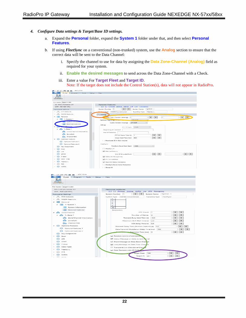
4. Configure Data settings & Target/Base ID settings.
Expand the Personal folder, expand the System 1 folder under that, and then select Personal Features.
If using FleetSync on a conventional (non-trunked) system, use the Analog section to ensure that the correct data will be sent to the Data Channel:
i. Specify the channel to use for data by assigning the Data Zone-Channel (Analog) field as required for your system.
ii. Enable the desired messages to send across the Data Zone-Channel with a Check.
iii. Enter a value For Target Fleet and Target ID. Note: If the target does not include the Control Station(s), data will not appear in RadioPro.
RadioPro IP Gateway Installation and Configuration Guide NEXEDGE NX-57xx/58xx
23
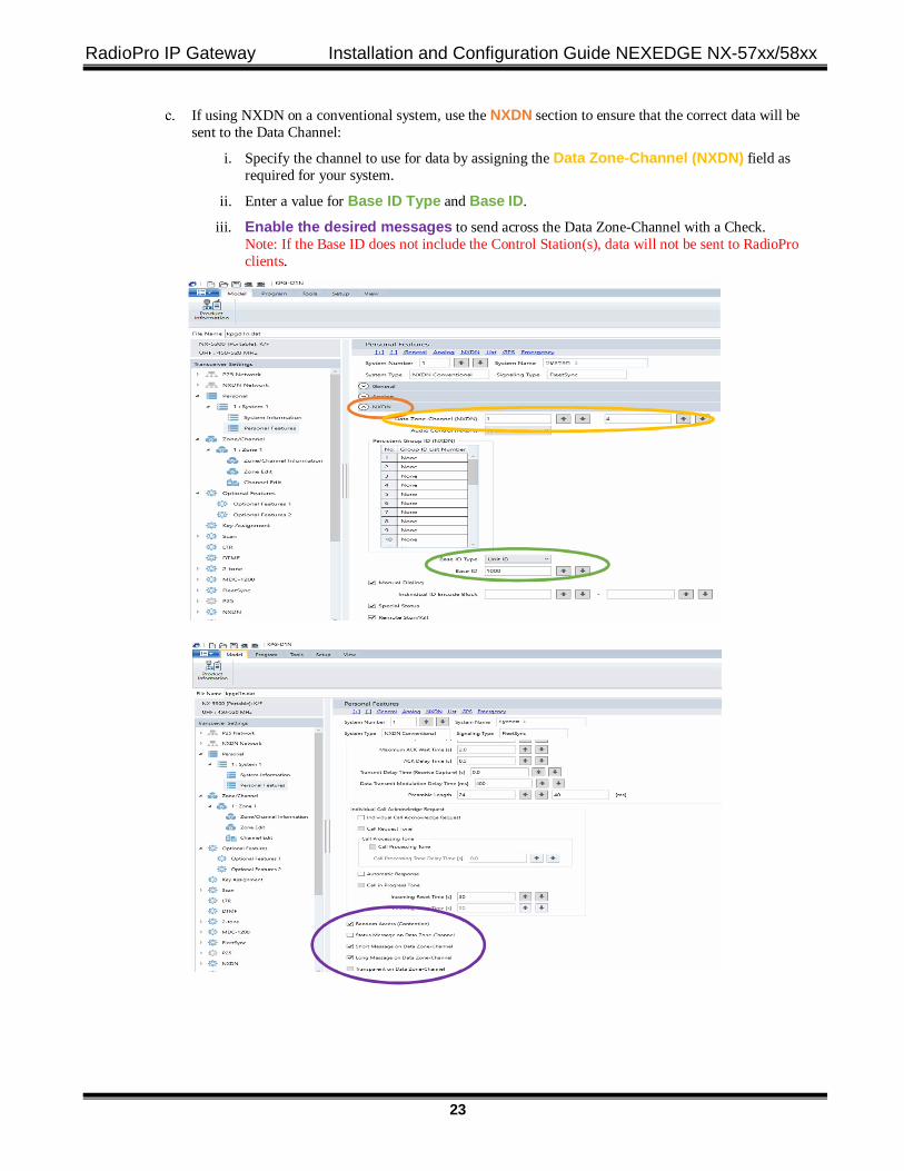
If using NXDN on a conventional system, use the NXDN section to ensure that the correct data will be sent to the Data Channel:
i. Specify the channel to use for data by assigning the Data Zone-Channel (NXDN) field as required for your system.
ii. Enter a value for Base ID Type and Base ID.
iii. Enable the desired messages to send across the Data Zone-Channel with a Check. Note: If the Base ID does not include the Control Station(s), data will not be sent to RadioPro clients.
RadioPro IP Gateway Installation and Configuration Guide NEXEDGE NX-57xx/58xx
24
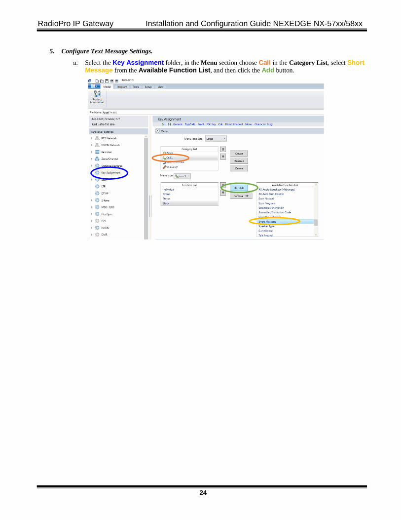
5. Configure Text Message Settings.
Select the Key Assignment folder, in the Menu section choose Call in the Category List, select Short Message from the Available Function List, and then click the Add button.
RadioPro IP Gateway Installation and Configuration Guide NEXEDGE NX-57xx/58xx
25
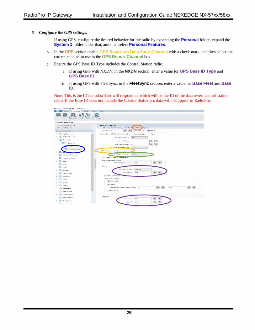
6. Configure the GPS settings.
If using GPS, configure the desired behavior for the radio by expanding the Personal folder, expand the System 1 folder under that, and then select Personal Features.
In the GPS section enable GPS Report on Data Zone-Channel with a check mark, and then select the correct channel to use in the GPS Report Channel box.
Ensure the GPS Base ID Type includes the Control Station radio.
i. If using GPS with NXDN, in the NXDN section, enter a value for GPS Base ID Type and GPS Base ID.
ii. If using GPS with FleetSync, in the FleetSync section, enter a value for Base Fleet and Base ID.
Note: This is the ID the subscriber will respond to, which will be the ID of the data revert control station radio. If the Base ID does not include the Control Station(s), data will not appear in RadioPro.
RadioPro IP Gateway Installation and Configuration Guide NEXEDGE NX-57xx/58xx
26
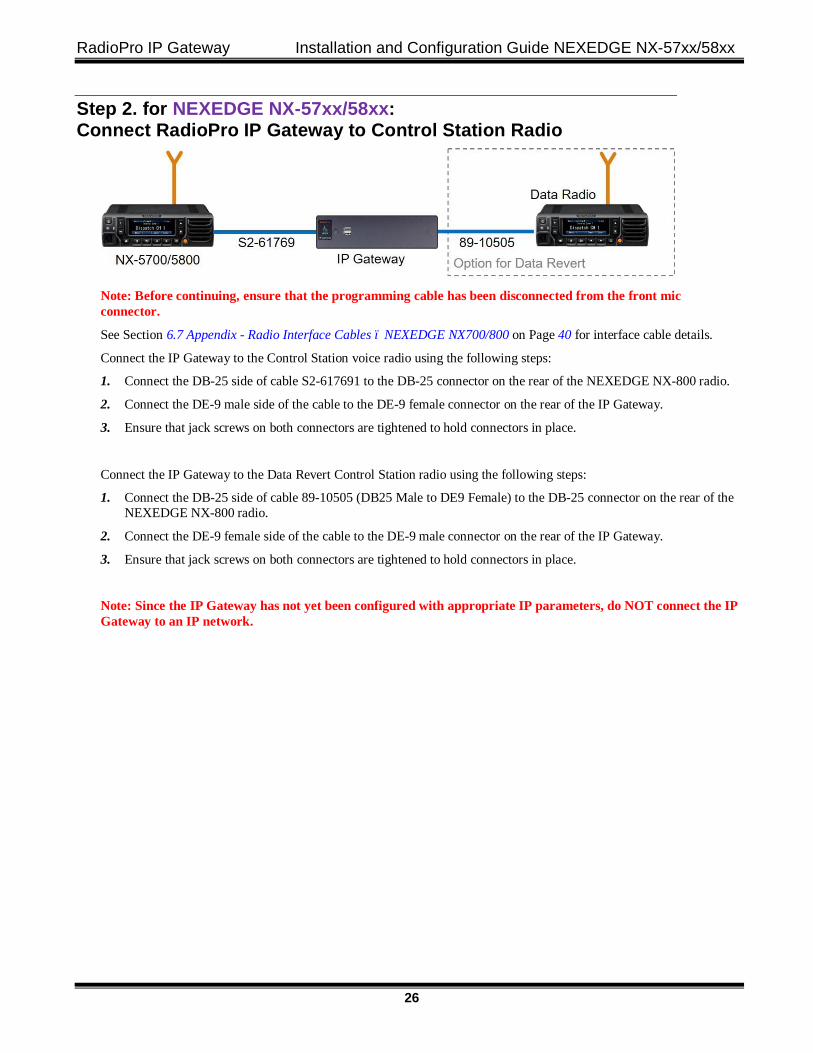
Step 2. for NEXEDGE NX-57xx/58xx: Connect RadioPro IP Gateway to Control Station Radio
Note: Before continuing, ensure that the programming cable has been disconnected from the front mic connector.
See Section 6.7 Appendix - Radio Interface Cables – NEXEDGE NX700/800 on Page 40 for interface cable details.
Connect the IP Gateway to the Control Station voice radio using the following steps:
1. Connect the DB-25 side of cable S2-617691 to the DB-25 connector on the rear of the NEXEDGE NX-800 radio.
2. Connect the DE-9 male side of the cable to the DE-9 female connector on the rear of the IP Gateway.
3. Ensure that jack screws on both connectors are tightened to hold connectors in place.
Connect the IP Gateway to the Data Revert Control Station radio using the following steps:
1. Connect the DB-25 side of cable 89-10505 (DB25 Male to DE9 Female) to the DB-25 connector on the rear of the NEXEDGE NX-800 radio.
2. Connect the DE-9 female side of the cable to the DE-9 male connector on the rear of the IP Gateway.
3. Ensure that jack screws on both connectors are tightened to hold connectors in place.
Note: Since the IP Gateway has not yet been configured with appropriate IP parameters, do NOT connect the IP Gateway to an IP network.
RadioPro IP Gateway Installation and Configuration Guide NEXEDGE NX-57xx/58xx
27
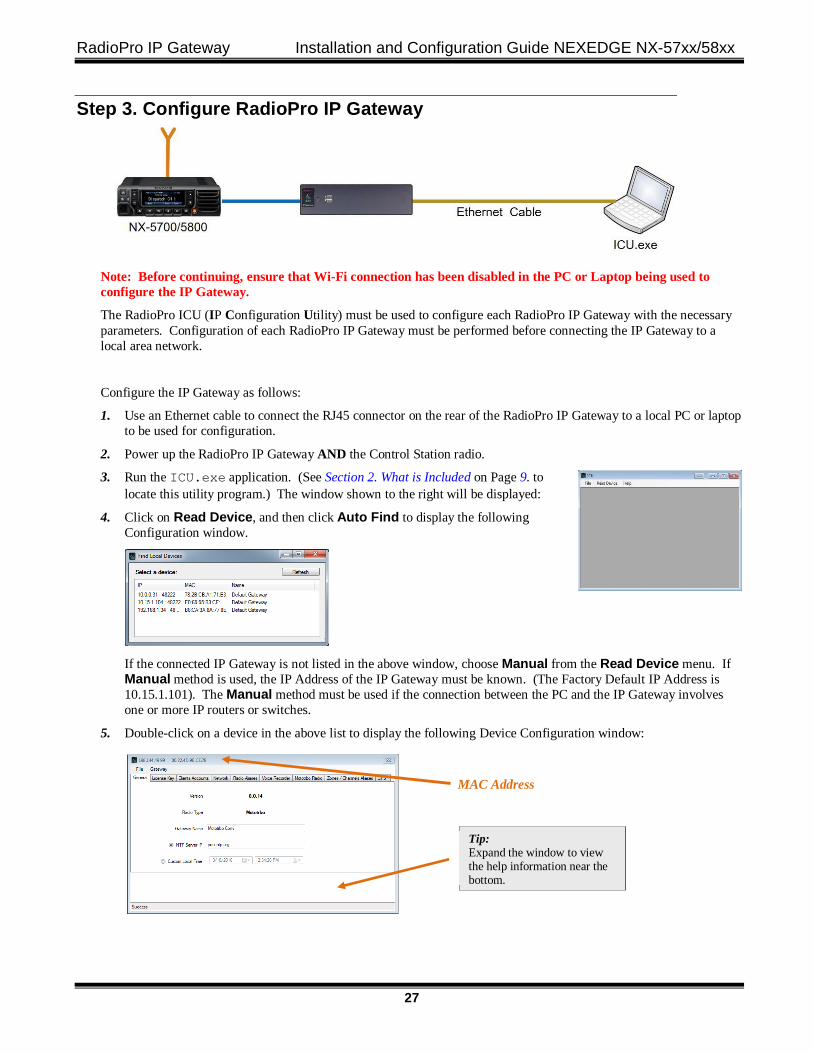
Step 3. Configure RadioPro IP Gateway
Note: Before continuing, ensure that Wi-Fi connection has been disabled in the PC or Laptop being used to configure the IP Gateway.
The RadioPro ICU (IP Configuration Utility) must be used to configure each RadioPro IP Gateway with the necessary parameters. Configuration of each RadioPro IP Gateway must be performed before connecting the IP Gateway to a local area network.
Configure the IP Gateway as follows:
1. Use an Ethernet cable to connect the RJ45 connector on the rear of the RadioPro IP Gateway to a local PC or laptop to be used for configuration.
2. Power up the RadioPro IP Gateway AND the Control Station radio.
3. Run the ICU.exe application. (See Section 2. What is Included on Page 9. to locate this utility program.) The window shown to the right will be displayed:
4. Click on Read Device, and then click Auto Find to display the following Configuration window.
If the connected IP Gateway is not listed in the above window, choose Manual from the Read Device menu. If Manual method is used, the IP Address of the IP Gateway must be known. (The Factory Default IP Address is 10.15.1.101). The Manual method must be used if the connection between the PC and the IP Gateway involves one or more IP routers or switches.
5. Double-click on a device in the above list to display the following Device Configuration window:
MAC Address
Tip: Expand the window to view the help information near the bottom.
RadioPro IP Gateway Installation and Configuration Guide NEXEDGE NX-57xx/58xx
28
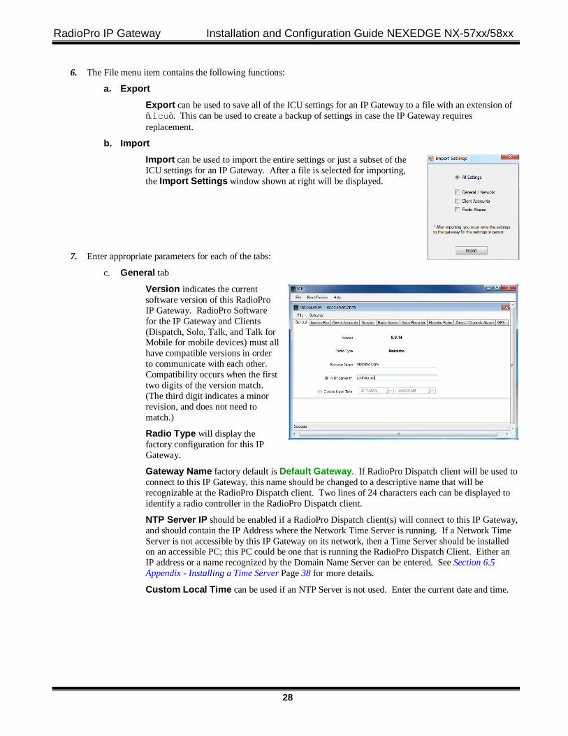
6. The File menu item contains the following functions:
a. Export Export can be used to save all of the ICU settings for an IP Gateway to a file with an extension of “.icu”. This can be used to create a backup of settings in case the IP Gateway requires replacement.
b. Import Import can be used to import the entire settings or just a subset of the ICU settings for an IP Gateway. After a file is selected for importing, the Import Settings window shown at right will be displayed.
7. Enter appropriate parameters for each of the tabs:
c. General tab
Version indicates the current software version of this RadioPro IP Gateway. RadioPro Software for the IP Gateway and Clients (Dispatch, Solo, Talk, and Talk for Mobile for mobile devices) must all have compatible versions in order to communicate with each other. Compatibility occurs when the first two digits of the version match. (The third digit indicates a minor revision, and does not need to match.)
Radio Type will display the factory configuration for this IP Gateway.
Gateway Name factory default is Default Gateway. If RadioPro Dispatch client will be used to connect to this IP Gateway, this name should be changed to a descriptive name that will be recognizable at the RadioPro Dispatch client. Two lines of 24 characters each can be displayed to identify a radio controller in the RadioPro Dispatch client.
NTP Server IP should be enabled if a RadioPro Dispatch client(s) will connect to this IP Gateway, and should contain the IP Address where the Network Time Server is running. If a Network Time Server is not accessible by this IP Gateway on its network, then a Time Server should be installed on an accessible PC; this PC could be one that is running the RadioPro Dispatch Client. Either an IP address or a name recognized by the Domain Name Server can be entered. See Section 6.5 Appendix - Installing a Time Server Page 38 for more details.
Custom Local Time can be used if an NTP Server is not used. Enter the current date and time.
RadioPro IP Gateway Installation and Configuration Guide NEXEDGE NX-57xx/58xx
29
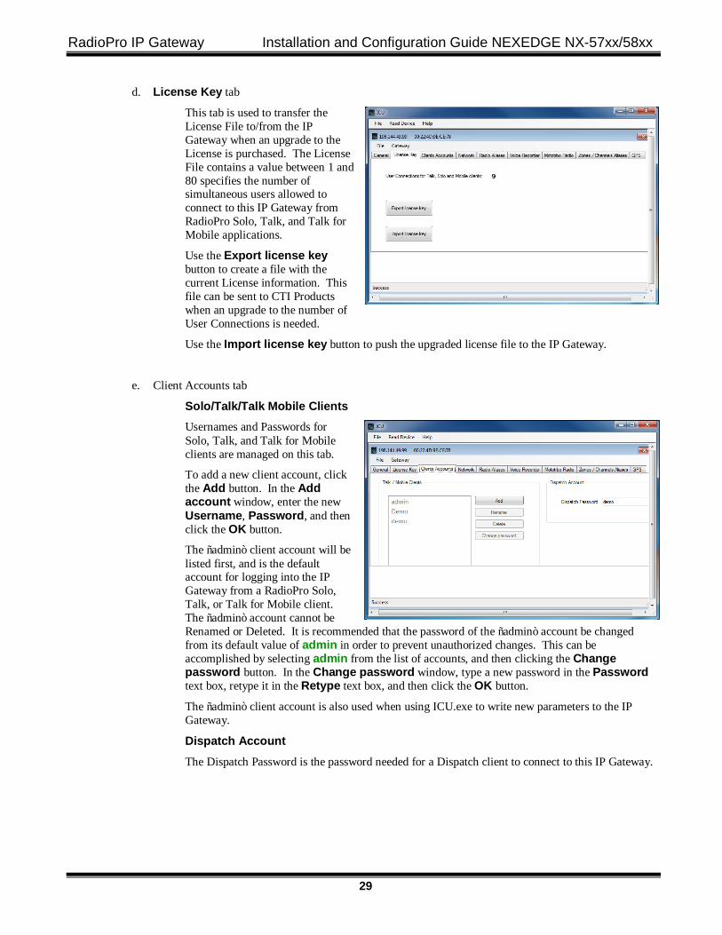
d. License Key tab
This tab is used to transfer the License File to/from the IP Gateway when an upgrade to the License is purchased. The License File contains a value between 1 and 80 specifies the number of simultaneous users allowed to connect to this IP Gateway from RadioPro Solo, Talk, and Talk for Mobile applications.
Use the Export license key button to create a file with the current License information. This file can be sent to CTI Products when an upgrade to the number of User Connections is needed.
Use the Import license key button to push the upgraded license file to the IP Gateway.
e. Client Accounts tab
Solo/Talk/Talk Mobile Clients Usernames and Passwords for Solo, Talk, and Talk for Mobile clients are managed on this tab.
To add a new client account, click the Add button. In the Add account window, enter the new Username, Password, and then click the OK button.
The “admin” client account will be listed first, and is the default account for logging into the IP Gateway from a RadioPro Solo, Talk, or Talk for Mobile client. The “admin” account cannot be Renamed or Deleted. It is recommended that the password of the “admin” account be changed from its default value of admin in order to prevent unauthorized changes. This can be accomplished by selecting admin from the list of accounts, and then clicking the Change password button. In the Change password window, type a new password in the Password text box, retype it in the Retype text box, and then click the OK button.
The “admin” client account is also used when using ICU.exe to write new parameters to the IP Gateway.
Dispatch Account The Dispatch Password is the password needed for a Dispatch client to connect to this IP Gateway.
RadioPro IP Gateway Installation and Configuration Guide NEXEDGE NX-57xx/58xx
30
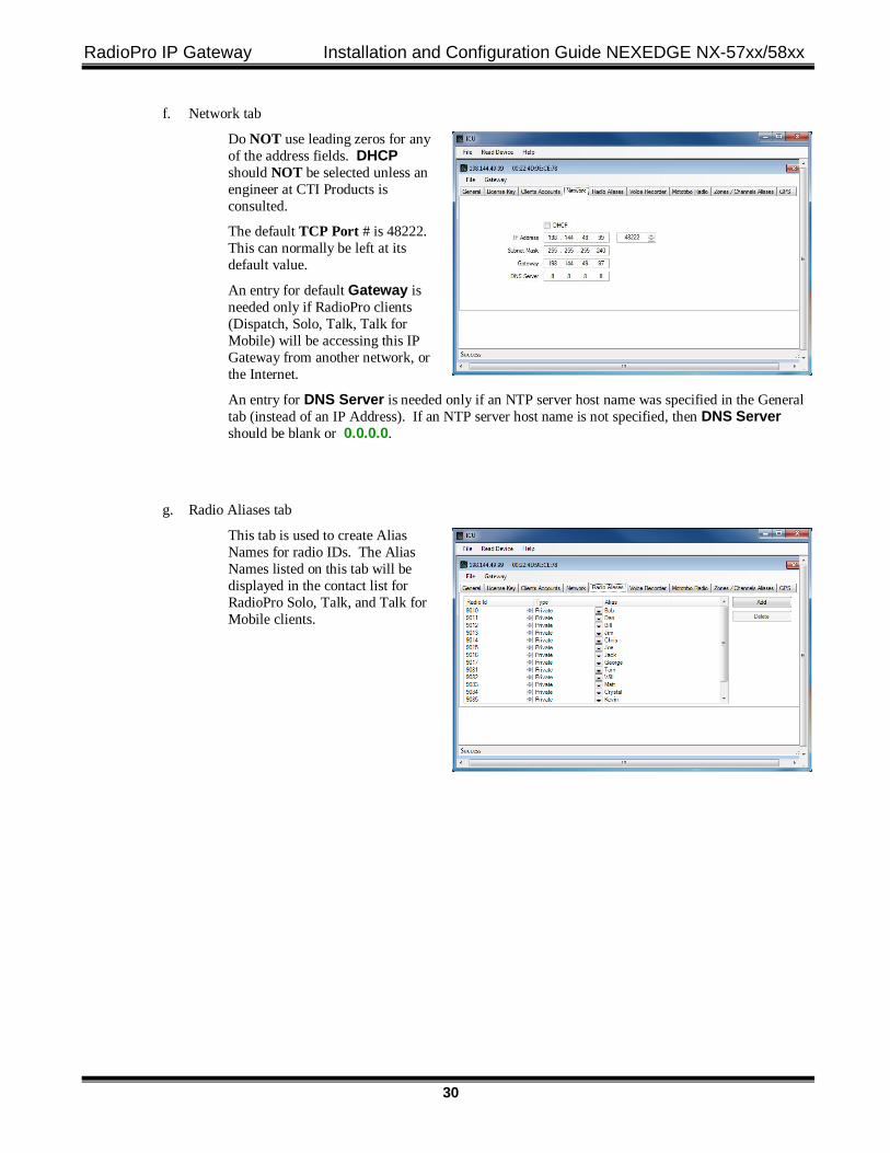
f. Network tab
Do NOT use leading zeros for any of the address fields. DHCP should NOT be selected unless an engineer at CTI Products is consulted.
The default TCP Port # is 48222. This can normally be left at its default value.
An entry for default Gateway is needed only if RadioPro clients (Dispatch, Solo, Talk, Talk for Mobile) will be accessing this IP Gateway from another network, or the Internet.
An entry for DNS Server is needed only if an NTP server host name was specified in the General tab (instead of an IP Address). If an NTP server host name is not specified, then DNS Server should be blank or 0.0.0.0.
g. Radio Aliases tab
This tab is used to create Alias Names for radio IDs. The Alias Names listed on this tab will be displayed in the contact list for RadioPro Solo, Talk, and Talk for Mobile clients.
RadioPro IP Gateway Installation and Configuration Guide NEXEDGE NX-57xx/58xx
31
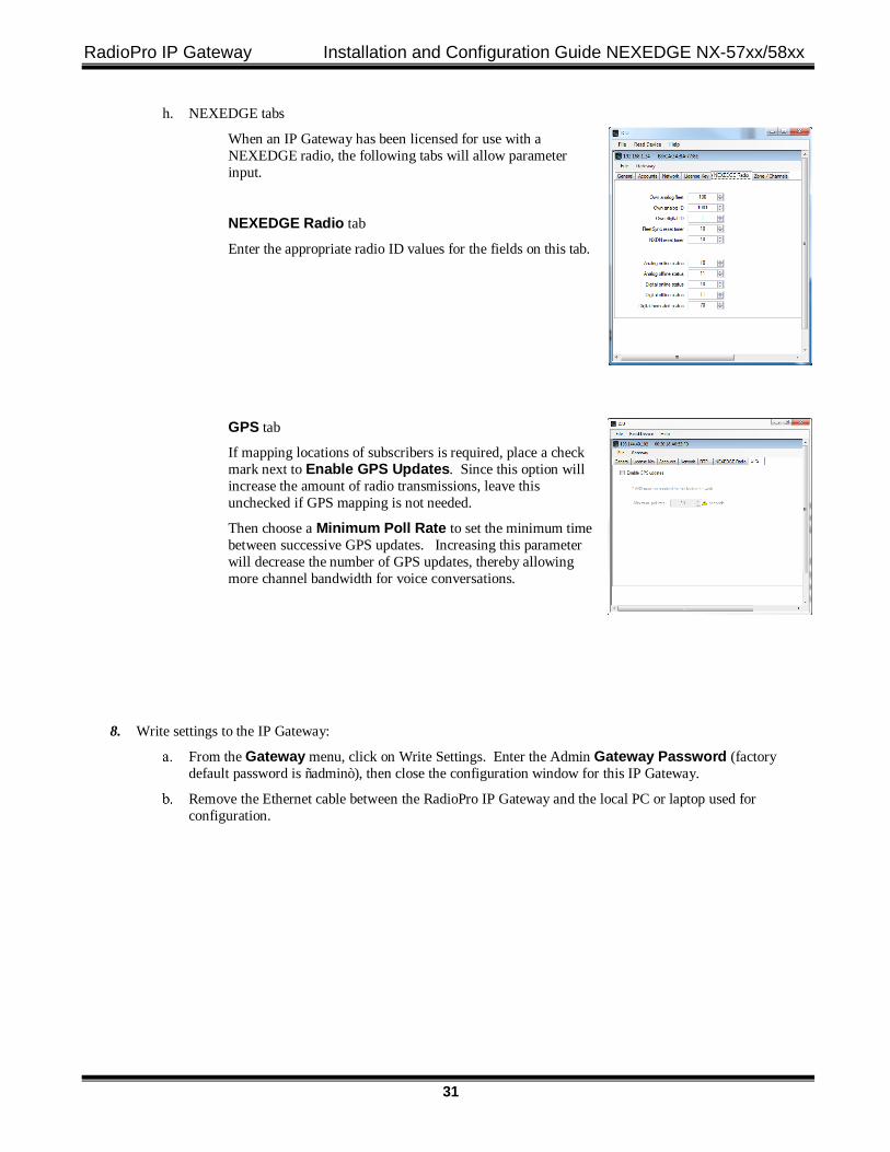
h. NEXEDGE tabs
When an IP Gateway has been licensed for use with a NEXEDGE radio, the following tabs will allow parameter input.
NEXEDGE Radio tab
Enter the appropriate radio ID values for the fields on this tab.
GPS tab
If mapping locations of subscribers is required, place a check mark next to Enable GPS Updates. Since this option will increase the amount of radio transmissions, leave this unchecked if GPS mapping is not needed.
Then choose a Minimum Poll Rate to set the minimum time between successive GPS updates. Increasing this parameter will decrease the number of GPS updates, thereby allowing more channel bandwidth for voice conversations.
8. Write settings to the IP Gateway:
From the Gateway menu, click on Write Settings. Enter the Admin Gateway Password (factory default password is “admin”), then close the configuration window for this IP Gateway.
Remove the Ethernet cable between the RadioPro IP Gateway and the local PC or laptop used for configuration.
RadioPro IP Gateway Installation and Configuration Guide NEXEDGE NX-57xx/58xx
32
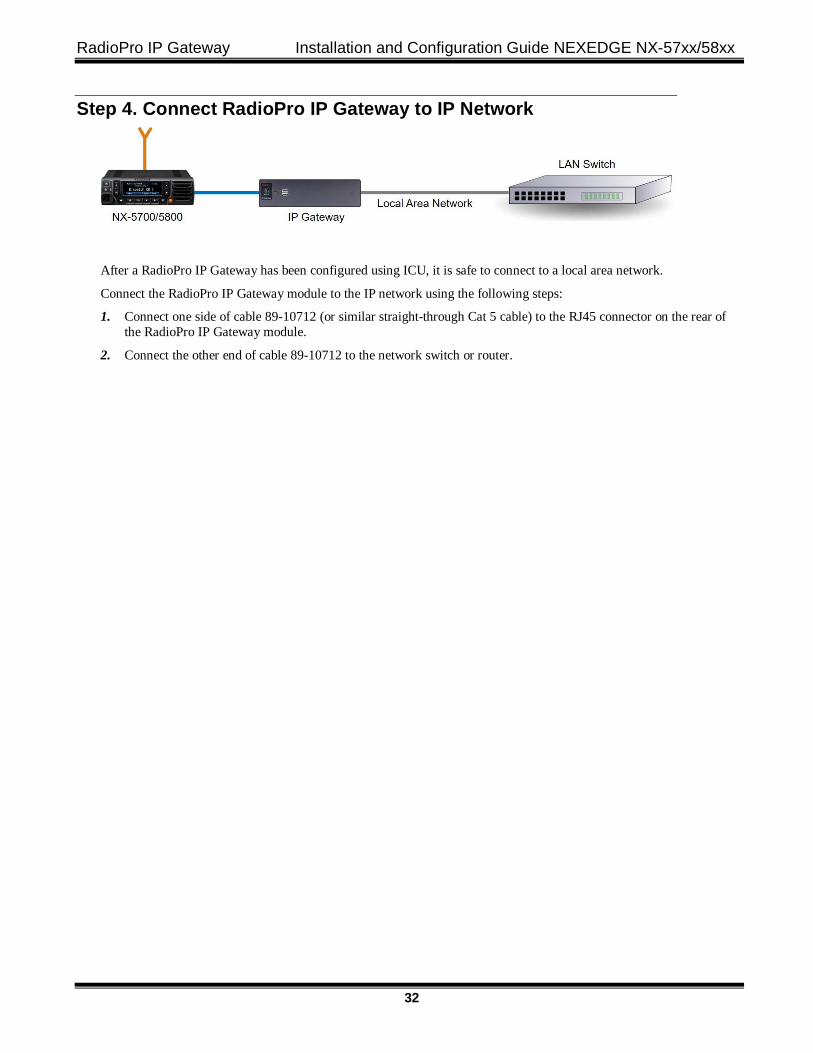
Step 4. Connect RadioPro IP Gateway to IP Network
After a RadioPro IP Gateway has been configured using ICU, it is safe to connect to a local area network.
Connect the RadioPro IP Gateway module to the IP network using the following steps:
1. Connect one side of cable 89-10712 (or similar straight-through Cat 5 cable) to the RJ45 connector on the rear of the RadioPro IP Gateway module.
2. Connect the other end of cable 89-10712 to the network switch or router.
RadioPro IP Gateway Installation and Configuration Guide NEXEDGE NX-57xx/58xx
33
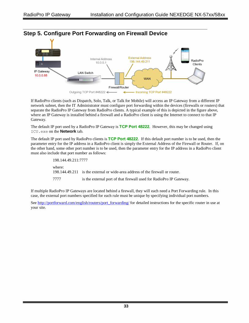
Step 5. Configure Port Forwarding on Firewall Device
If RadioPro clients (such as Dispatch, Solo, Talk, or Talk for Mobile) will access an IP Gateway from a different IP network subnet, then the IT Administrator must configure port forwarding within the devices (firewalls or routers) that separate the RadioPro IP Gateway from RadioPro clients. A typical example of this is depicted in the figure above, where an IP Gateway is installed behind a firewall and a RadioPro client is using the Internet to connect to that IP Gateway.
The default IP port used by a RadioPro IP Gateway is TCP Port 48222. However, this may be changed using ICU.exe on the Network tab.
The default IP port used by RadioPro clients is TCP Port 48222. If this default port number is to be used, then the parameter entry for the IP address in a RadioPro client is simply the External Address of the Firewall or Router. If, on the other hand, some other port number is to be used, then the parameter entry for the IP address in a RadioPro client must also include that port number as follows:
198.144.49.211:7777
where: 198.144.49.211 is the external or wide-area address of the firewall or router.
7777 is the external port of that firewall used for RadioPro IP Gateway.
If multiple RadioPro IP Gateways are located behind a firewall, they will each need a Port Forwarding rule. In this case, the external port numbers specified for each rule must be unique by specifying individual port numbers.
See http://portforward.com/english/routers/port_forwarding/ for detailed instructions for the specific router in use at your site.
RadioPro IP Gateway Installation and Configuration Guide NEXEDGE NX-57xx/58xx
34
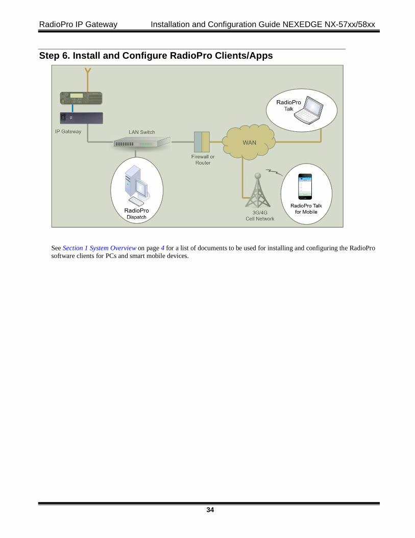
Step 6. Install and Configure RadioPro Clients/Apps
See Section 1 System Overview on page 4 for a list of documents to be used for installing and configuring the RadioPro software clients for PCs and smart mobile devices.
RadioPro IP Gateway Installation and Configuration Guide NEXEDGE NX-57xx/58xx
35
5. RADIOPRO IP GATEWAY OPERATION
5.1 Power-up The Power Button can be used to power up or power down the unit by pressing it momentarily.
A watchdog circuit built into the IP Gateway monitors program operation. If the watchdog circuit detects that the program is not functioning correctly, it will re-initialize the IP Gateway. This process may take up to two minutes. During this process, RadioPro Dispatch, Solo, Talk, or Talk for Mobile clients will not have a connection or communication with the Control Station radio.
5.2 Indicators A blue LED located on the Power Button indicates that power is applied to the IP Gateway.
A red LED located internally, but viewable through the vents on the left side of the IP Gateway indicates the functioning of the Hardware Watchdog as follows:
• “Slow Blinking” (2 seconds per blink) indicates that the IP Gateway is rebooting. This will normally occur for a maximum of two minutes after power-up.
• “Steady” illumination indicates that the IP Gateway software and hardware is operating correctly, and follows the “Slow Blinking” boot-up period.
• “Fast Blinking” (1 second per blink) indicates that the watch-dog circuitry has detected a problem, and that re-booting will commence within 5 seconds.
RadioPro IP Gateway Installation and Configuration Guide NEXEDGE NX-57xx/58xx
36
6. APPENDIX
6.1 Appendix - RadioPro IP Gateway Specifications
Mechanical and Environmental Dimensions: 9.0”w x 2.5”h x 7.7”d Weight: 3 lbs. Temperature Range: 0-50 oC Humidity: 10-95% non-condensing
Electrical AC Input (with included Power Adapter): 100–240Vac, 60W max, 50-60Hz DC Input, SNs before 3154: 11.5-12.5VDC Only DC Input, SNs after 3154: 12-30VDC (with optional PS upgrade)
Service Ports Port Forwarding (for firewall configuration) TCP Port 48222 (default) Ports used by ICU.exe during configuration UDP Ports 48501 and 48502 Port for Network Time Protocol Service UDP Port 123 Port used for Remote Desktop Service TCP Port 48333 (used only when remote technical service is needed)
Miscellaneous MOTOTRBO interface DE-9 Female & USB, Cable S2-61431 NEXEDGE NX-7xx/8xx/57xx/58xx interface DB-25 Female, Cable S2-61769 NEXEDGE NX-720/820 interface DB-25 Female, Cable S2-61890 Transmit/Receive Impedance - MOTOTRBO 600 ohms Transmit/Receive Impedance – Kenwood 10k ohms Clients Supported 80 Solo, Talk, or Talk for Mobile, plus 12 Dispatch Power-On Auto Network Bandwidth (for each connected client) 2.2k Bytes per Second with audio compression enabled 22k Bytes per Second without audio compression
6.2 Appendix - IP Addressing Normally, the factory default IP Address programmed into the Control Station radio should not be changed. However, it must be on a different subnet than the RadioPro IP Gateway that is connected to it via the Rear Accessory Connector.
For example, if the network’s Subnet Mask is 255.255.255.0, then at least one of the first three octets of the MOTOTRBO radio IP address must be different than the RadioPro IP Gateway module IP address.
The following IS NOT a valid IP addressing scheme since both devices are on the SAME subnet: Control Station Radio RadioPro IP Gateway IP Address: 192.168.12.2 192.168.12.3 Subnet Mask: 255.255.255.0 255.255.255.0
The following IS a valid IP addressing scheme since the devices are on DIFFERENT subnets: Control Station Radio RadioPro IP Gateway IP Address: 192.168.12.2 192.168.10.3 Subnet Mask: 255.255.255.0 255.255.255.0
For additional information see Cisco’s “IP Addressing and Subnetting for New Users”, Document ID 13788, located at: http://www.cisco.com/en/US/tech/tk365/technologies_tech_note09186a00800a67f5.shtml
RadioPro IP Gateway Installation and Configuration Guide NEXEDGE NX-57xx/58xx
37
6.3 Appendix - Rack Mounting
Rack Shelf A rack shelf can be used to hold the RadioPro IP Gateway and Control Station radio in a standard 19” wide rack. The two devices can be located next to each other on the same shelf. The following rack shelf is recommended, but others may be used that have a depth of at least 12”:
Rack Shelf 2RU x 15”, CTI Products # S2-61548, also available as Cable Organizer # QES0319-0215: http://www.cableorganizer.com/computer-cabinets/rack-shelves/single-side-non-vented-shelves.html
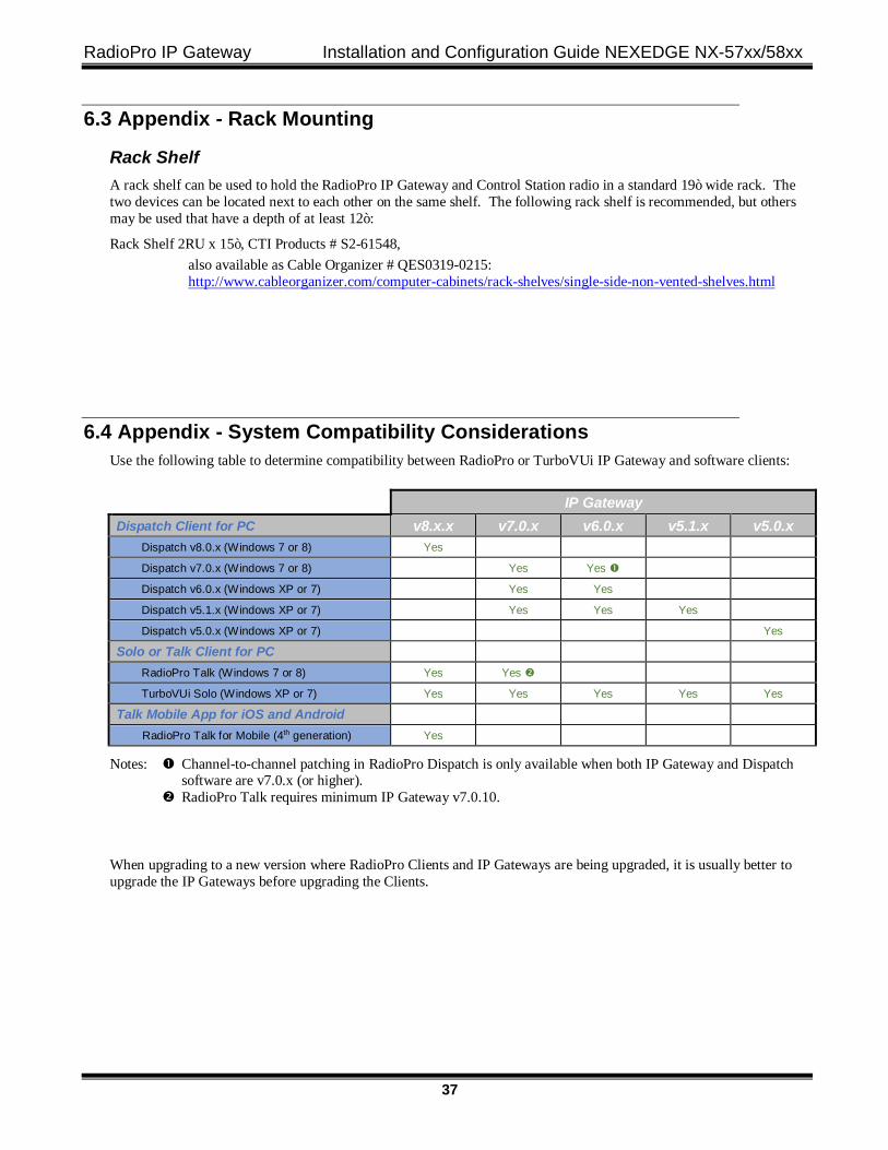
6.4 Appendix - System Compatibility Considerations Use the following table to determine compatibility between RadioPro or TurboVUi IP Gateway and software clients:
IP Gateway Dispatch Client for PC v8.x.x v7.0.x v6.0.x v5.1.x v5.0.x Dispatch v8.0.x (Windows 7 or 8) Yes
Dispatch v7.0.x (Windows 7 or 8) Yes Yes �
Dispatch v6.0.x (Windows XP or 7) Yes Yes
Dispatch v5.1.x (Windows XP or 7) Yes Yes Yes
Dispatch v5.0.x (Windows XP or 7) Yes
Solo or Talk Client for PC
RadioPro Talk (Windows 7 or 8) Yes Yes �
TurboVUi Solo (Windows XP or 7) Yes Yes Yes Yes Yes
Talk Mobile App for iOS and Android
RadioPro Talk for Mobile (4th generation) Yes
Notes: � Channel-to-channel patching in RadioPro Dispatch is only available when both IP Gateway and Dispatch software are v7.0.x (or higher). � RadioPro Talk requires minimum IP Gateway v7.0.10.
When upgrading to a new version where RadioPro Clients and IP Gateways are being upgraded, it is usually better to upgrade the IP Gateways before upgrading the Clients.
RadioPro IP Gateway Installation and Configuration Guide NEXEDGE NX-57xx/58xx
38
6.5 Appendix - Installing a Time Server During installation of the IP Gateways, the IP address of a “NTP Server” may have been specified using the ICU (IP Configuration Utility). In order for all IP Gateways to report the same time, and logging at the Dispatch client to have accurate times, the IP Gateways must all reference the same Time Server. This Time Server can be one of the following:
• An existing Time Server on the Local Area Network. • Public domain Time Server accessed using the Internet. • Local Time Server installed on a common PC, such as the Dispatch client console PC.
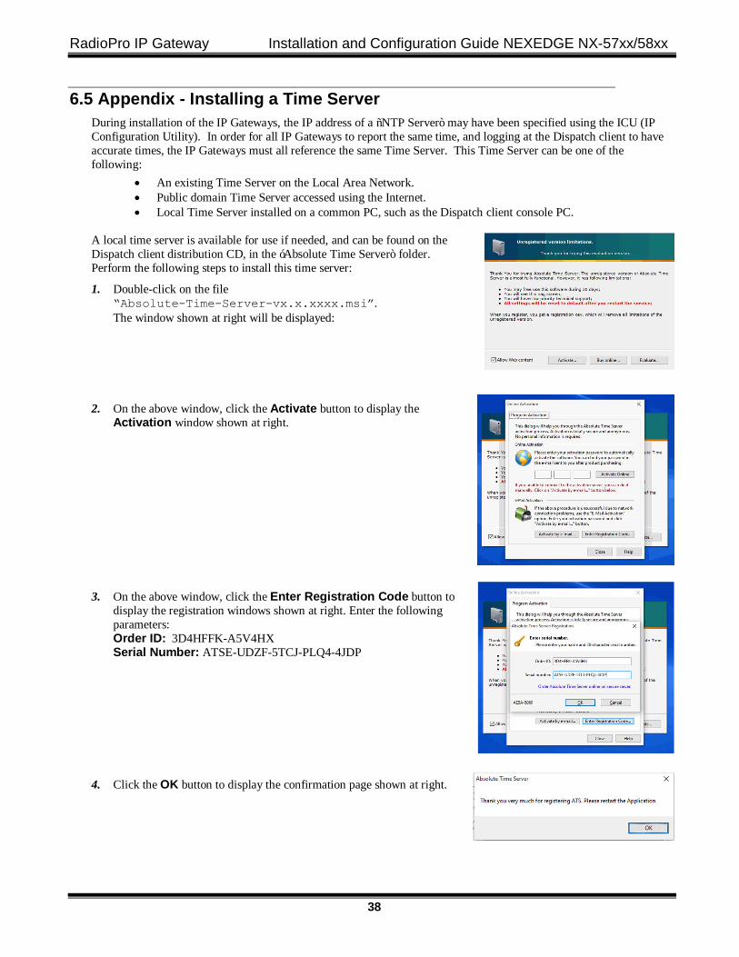
A local time server is available for use if needed, and can be found on the Dispatch client distribution CD, in the ‘Absolute Time Server” folder. Perform the following steps to install this time server:
1. Double-click on the file “Absolute-Time-Server-vx.x.xxxx.msi”. The window shown at right will be displayed:
2. On the above window, click the Activate button to display the Activation window shown at right.
3. On the above window, click the Enter Registration Code button to display the registration windows shown at right. Enter the following parameters: Order ID: 3D4HFFK-A5V4HX Serial Number: ATSE-UDZF-5TCJ-PLQ4-4JDP
4. Click the OK button to display the confirmation page shown at right.
RadioPro IP Gateway Installation and Configuration Guide NEXEDGE NX-57xx/58xx
39
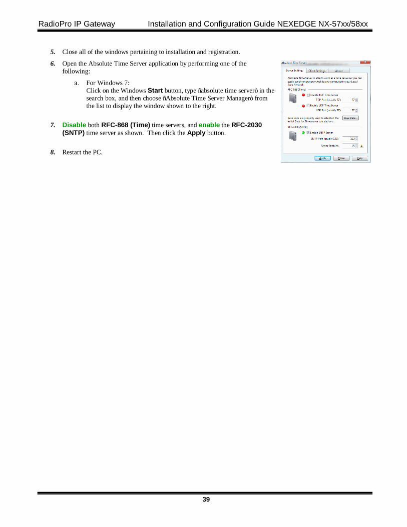
5. Close all of the windows pertaining to installation and registration.
6. Open the Absolute Time Server application by performing one of the following:
For Windows 7: Click on the Windows Start button, type “absolute time server” in the search box, and then choose “Absolute Time Server Manager” from the list to display the window shown to the right.
7. Disable both RFC-868 (Time) time servers, and enable the RFC-2030 (SNTP) time server as shown. Then click the Apply button.
8. Restart the PC.
RadioPro IP Gateway Installation and Configuration Guide NEXEDGE NX-57xx/58xx
40
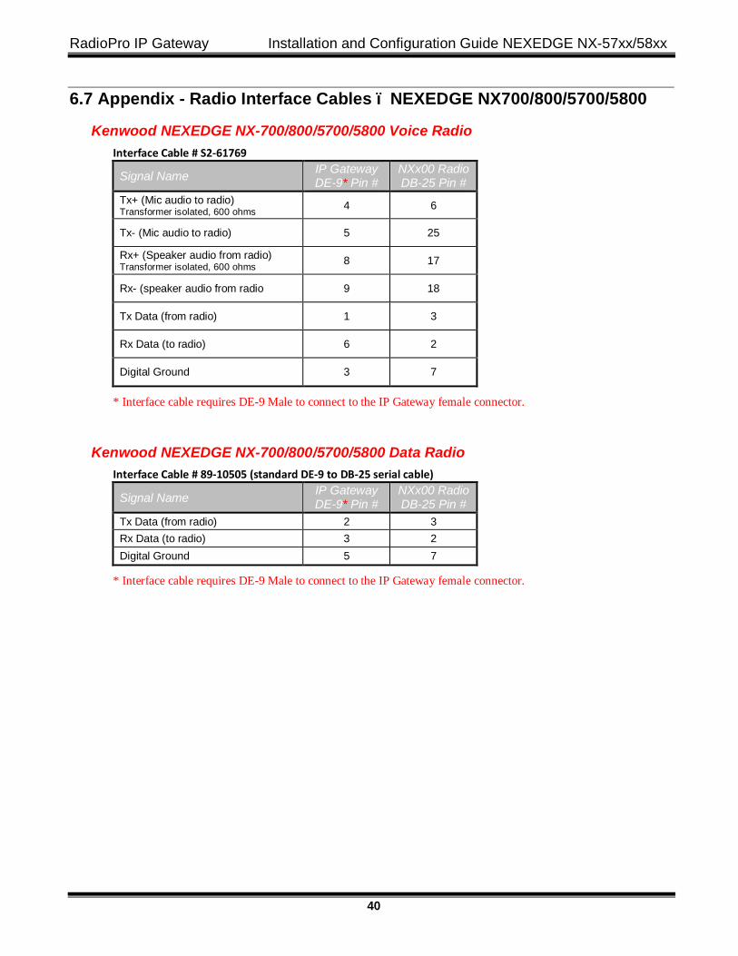
6.7 Appendix - Radio Interface Cables – NEXEDGE NX700/800/5700/5800
Kenwood NEXEDGE NX-700/800/5700/5800 Voice Radio Interface Cable # S2-61769
Signal Name IP Gateway DE-9* Pin #
NXx00 Radio DB-25 Pin #
Tx+ (Mic audio to radio) Transformer isolated, 600 ohms 4 6
Tx- (Mic audio to radio) 5 25
Rx+ (Speaker audio from radio) Transformer isolated, 600 ohms 8 17
Rx- (speaker audio from radio 9 18
Tx Data (from radio) 1 3
Rx Data (to radio) 6 2
Digital Ground 3 7
* Interface cable requires DE-9 Male to connect to the IP Gateway female connector.
Kenwood NEXEDGE NX-700/800/5700/5800 Data Radio Interface Cable # 89-10505 (standard DE-9 to DB-25 serial cable)
Signal Name IP Gateway DE-9* Pin #
NXx00 Radio DB-25 Pin #
Tx Data (from radio) 2 3 Rx Data (to radio) 3 2 Digital Ground 5 7
* Interface cable requires DE-9 Male to connect to the IP Gateway female connector.
RadioPro IP Gateway Installation and Configuration Guide NEXEDGE NX-57xx/58xx
41
6.7 Appendix - Converting a Timed-license to Non-expiring A RadioPro IP Gateway may have a timed-license duration of 120 days. (The Packing List will indicate Part # S2-61612 if the timed-license is active.) If the Timed-License is active, and following the 120-day period, the RadioPro IP Gateways will not connect to a RadioPro Dispatch, Solo, Talk, or Talk for Mobile client for longer than five minutes. See instructions below for converting the timed-license to a non-expiring license.
Following receipt of payment to CTI Products for ordered items, a request may be made to convert a timed license to a non-expiring license. Use the following steps to convert the license:
1. Use instructions for
RadioPro IP Gateway Installation and Configuration Guide NEXEDGE NX-57xx/58xx
42
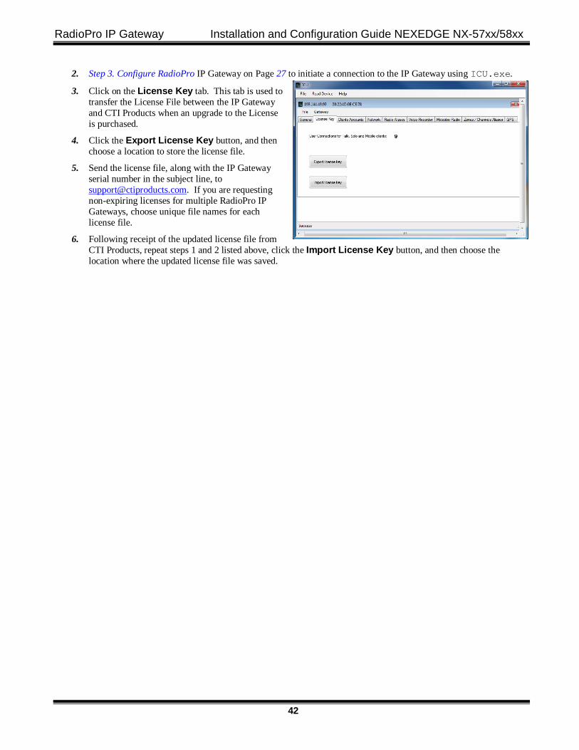
2. Step 3. Configure RadioPro IP Gateway on Page 27 to initiate a connection to the IP Gateway using ICU.exe.
3. Click on the License Key tab. This tab is used to transfer the License File between the IP Gateway and CTI Products when an upgrade to the License is purchased.
4. Click the Export License Key button, and then choose a location to store the license file.
5. Send the license file, along with the IP Gateway serial number in the subject line, to [email protected]. If you are requesting non-expiring licenses for multiple RadioPro IP Gateways, choose unique file names for each license file.
6. Following receipt of the updated license file from CTI Products, repeat steps 1 and 2 listed above, click the Import License Key button, and then choose the location where the updated license file was saved.
RadioPro IP Gateway Installation and Configuration Guide NEXEDGE NX-57xx/58xx
43
7. INDEX
A Accounts, 29 Admin, 31, 45 Android, 8, 28 Architecture, 6 Auto Find, 27
C Cable, 10, 26, 32 CD, 9 Contact us, 2 Control Station, 10, 11, 12, 19, 20, 35, 36 Control Station Radio, 6
D Default, 45 Default Gateway, 8, 45 Dispatch client, 8, 28, 45
E EMI, 7 ESD, 7
F Fire Protection, 7 Firewall, 8, 33
I ICU, 9, 10, 27, 32, 45
Accounts tab, 29 General tab, 28 Network tab, 29, 30 Radio tab, 31
Installation Guide, 46 IP Address, 8, 27, 28, 36, 45 IP Addressing, 36 IP Configuration Utility, 27 IP Gateway, 4, 6, 7, 10, 38, 41, 42, 45, 46 iPhone, 8
L LED
blue, 35 red, 35
Login, 46 Login Name, 46
M Mobile application, 5, 6 Mobile application, 4
N NEXEDGE, 12, 20 NTP Server, 28, 45
O Overview, 4
P Password, 31, 45, 46 Port Forwarding, 8, 33, 36 Power Button, 35 Power Requirements, 7 Programming Cable, 10, 26
Q Quick-Start Guide, 46
R RF Interference, 7 Router, 8, 27, 32, 33
S Specifications, 7, 36 Static IP Address, 8 Subnet Mask, 8, 36, 45 System Planner, 45, 46 System Planner Template, 45, 46
T Talk Client, 4, 5, 8 TCP Port, 33, 36 Text Messaging, 4 Time Server, 38, 39 Timed-License, 41
V Version, 1, 7 Vibration, 7 Virtual Private Network, 4, 5, 6 Voice and Event Logging, 4, 5
RadioPro IP Gateway Installation and Configuration Guide NEXEDGE NX-57xx/58xx
44
X XPR4550, 36
Rear Accessory Connector, 36
RadioPro IP Gateway Installation and Configuration Guide NEXEDGE NX-57xx/58xx
45
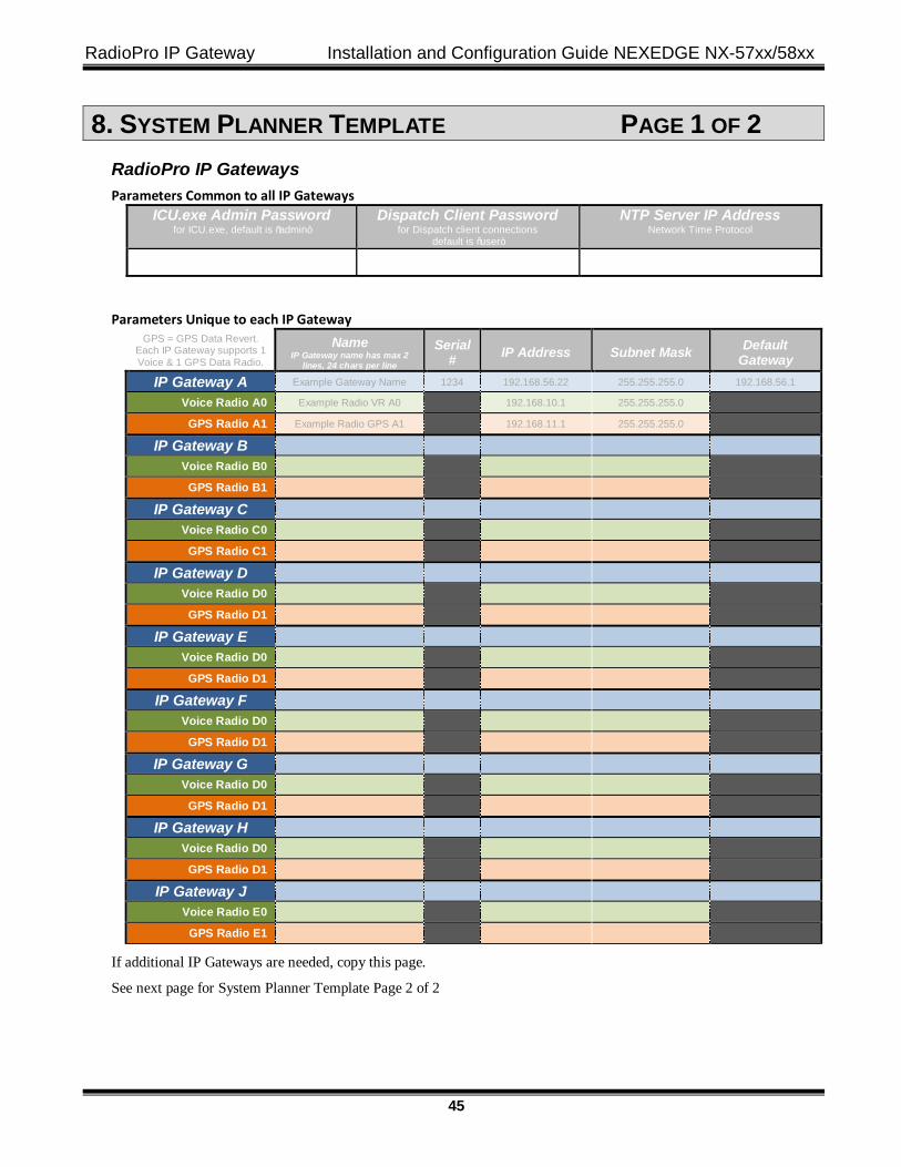
8. SYSTEM PLANNER TEMPLATE PAGE 1 OF 2 RadioPro IP Gateways Parameters Common to all IP Gateways
ICU.exe Admin Password for ICU.exe, default is “admin”
Dispatch Client Password for Dispatch client connections
default is “user” NTP Server IP Address
Network Time Protocol
Parameters Unique to each IP Gateway GPS = GPS Data Revert.
Each IP Gateway supports 1 Voice & 1 GPS Data Radio.
Name IP Gateway name has max 2
lines, 24 chars per line
Serial # IP Address Subnet Mask Default
Gateway IP Gateway A Example Gateway Name 1234 192.168.56.22 255.255.255.0 192.168.56.1
Voice Radio A0 Example Radio VR A0 192.168.10.1 255.255.255.0
GPS Radio A1 Example Radio GPS A1 192.168.11.1 255.255.255.0
IP Gateway B
Voice Radio B0
GPS Radio B1
IP Gateway C
Voice Radio C0
GPS Radio C1
IP Gateway D
Voice Radio D0
GPS Radio D1
IP Gateway E
Voice Radio D0
GPS Radio D1
IP Gateway F
Voice Radio D0
GPS Radio D1
IP Gateway G
Voice Radio D0
GPS Radio D1
IP Gateway H
Voice Radio D0
GPS Radio D1
IP Gateway J
Voice Radio E0
GPS Radio E1
If additional IP Gateways are needed, copy this page.
See next page for System Planner Template Page 2 of 2
RadioPro IP Gateway Installation and Configuration Guide NEXEDGE NX-57xx/58xx
46
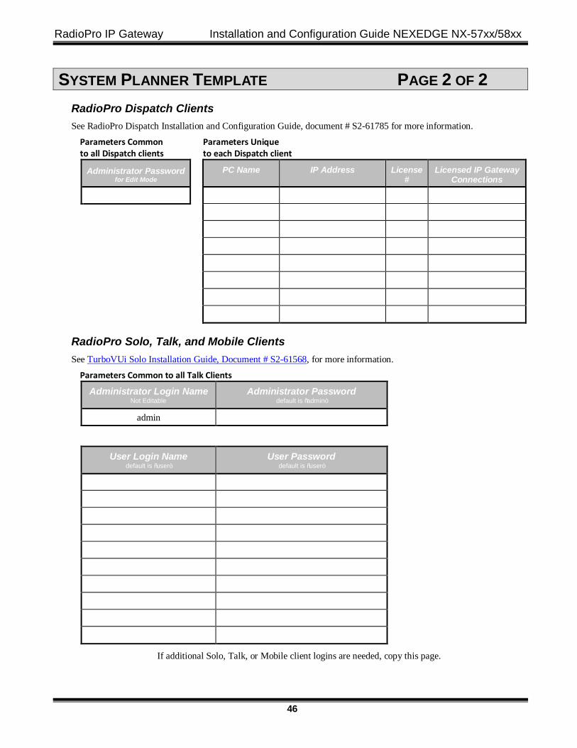
SYSTEM PLANNER TEMPLATE PAGE 2 OF 2 RadioPro Dispatch Clients See RadioPro Dispatch Installation and Configuration Guide, document # S2-61785 for more information.
Parameters Common Parameters Unique to all Dispatch clients to each Dispatch client
Administrator Password for Edit Mode
PC Name
IP Address
License #
Licensed IP Gateway Connections
RadioPro Solo, Talk, and Mobile Clients See TurboVUi Solo Installation Guide, Document # S2-61568, for more information.
Parameters Common to all Talk Clients
Administrator Login Name Not Editable
Administrator Password default is “admin”
admin
User Login Name default is “user”
User Password default is “user”
If additional Solo, Talk, or Mobile client logins are needed, copy this page.
Related Documents