Radiochromic Film David F. Lewis, Ph.D. Senior Science Fellow Advanced Materials Group International Specialty Products [email protected] October 20, 2010

Welcome message from author
This document is posted to help you gain knowledge. Please leave a comment to let me know what you think about it! Share it to your friends and learn new things together.
Transcript

Radiochromic Film
David F. Lewis, Ph.D.
Senior Science Fellow
Advanced Materials Group
International Specialty Products
October 20, 2010

High Resolution Imaging
• 1984: Could we make a processless film for recording very high resolution images in an electron-beam recorder? – Tri-phenyl methane dyes in PVC
• Photolysis produces HCl and activates a pH-sensitive leuco-dye
• No amplification - slow
– Diacetylenes • Solid-state polymerization
• >>100x amplification - faster

Performance of Photosensitive Systems
Silver halide – fast : 5x10⁻¹⁰J/cm2
Silver halide – slow: 10-8 J/cm2
Xerography: 10-6 J/cm2
Photopolymerization: 10-3 J/cm2
Photochromism: 1 J/cm2
Imaging Systems, Jacobson and Jacobson, Focal Press 1976

Amplification
• One photochemical event effecting >1 molecule
– Silver halide – a whole crystal, 1010 silver atoms, can become
developable after as few as 4 photochemical events
– Photopolymerization – up to thousands of monomer molecules
react to form a polymer

Processless Electron Recording Media 1988

1988 - Monochrome color 1996 – Monochrome B&W
1998 – Polychrome in one active layer

Core Radiochromic Film Technology
Original active component : Pentacosa-10,12-diynoic acid (PCDA)
Current active component is lithium pentacosa-10,12-diynoate (LiPCDA)
The diacetylene monomer must be in an ordered form to be active

Radiation Dosimetry Applications –
GAFCHROMIC® Films
Five products introduced between 1990 and 2002
Primarily for MeV radiation
• HD-810 transparent, single layer, 5 – 400Gy
• MD-55 transparent, laminated double layer, 1 – 80Gy
• HS transparent, laminated, single layer, 0.5 – 40Gy
Primarily for keV radiation
• XR-R opaque, laminated, single layer, 0.1 – 15Gy
• XR-T transparent, laminated, double layer, 0.02Gy – 10Gy

Features of radiochromic film include…
• No film processing
• No darkroom
• No chemicals
• Low energy dependence
• Fractionation independence
• Dose-rate independence
Quantitative film dosimetry also requires ….
•Film Digitizer
•Software

However, some issues prevented wide
clinical use…
• Dose range >10 Gy
• Non-uniformity
• Time/temperature effects
• Small film size
• Complicated protocols for use
– 4 days for measurement
– TG-55
• High price

Development of High Sensitivity Film
• Development began in December 2002
• GAFCHROMIC® RTQA – 2-500cGy, radiotherapy QA where use is qualitative
– Introduced July 2004
• GAFCHROMIC ® EBT – 1-800cGy, for quantitative film dosimetry, e.g. IMRT – Currently in final clinical evaluations
– Introduction late September 2004
• GAFCHROMIC ® XRQA – keV photons 0.1-20cGy – Currently in field evaluations
– Introduction about December 2004

Developing a 3D Radiochromic Gel Courtesy of James F. Dempsey, Univ. Of Florida
The novel film active layer was “discovered” while investigating a novel 3D radiochromic gel see Med. Phys. 30(6) (2003) 1425

Active Component is Hair-Like

A New Film is Developed Courtesy of James F. Dempsey, Univ. Of Florida
EBT is still a RCF, but it has new properties, the most promising of which, was it’s greatly increased radiosensitivity
LiPCDA – Active Component in EBT and EBT2

GAFCHROMIC® Dosimetry Films
Radiology/diagnostic Energy Range Dose Range
GAFCHROMIC® XR- R kV 0.1Gy to 15 Gy
GAFCHROMIC® XR-CT kV 0.1cGy to 20 cGy
GAFCHROMIC® XR-M kV 0.1cGy to 20 cGy
GAFCHROMIC® XR-QA kV 0.1cGy to 20 cGy
Radiotherapy Energy Range Dose Range
GAFCHROMIC® HD-810 MV 5Gy to 500Gy
GAFCHROMIC® MD-V2-55 MV 1Gy to 100Gy
GAFCHROMIC® RTQA MV 0.02Gy to 8Gy
GAFCHROMIC® EBT kV-MV up to 50Gy

GAFCHROMIC® EBT Coating
CLEAR POLYESTER ~97 microns
SURFACE LAYER ~3 microns
ACTIVE LAYER ~17 microns

EBT Film Structure and Composition
CLEAR POLYESTER - 97 microns
CLEAR POLYESTER - 97 microns
ACTIVE LAYER - 17 microns
ACTIVE LAYER - 17 micronsSURFACE LAYER - 6 microns
COMPOSITION (ATOM%)
C H O N Li Cl Zeff
25.0% 54.2% 9.6% 10.4% 0.7% 0.1% 7.14
22.5% 53.3% 11.1% 12.7% 0.2% 0.2% 6.84
45.5% 36.4% 18.2% 0.0% 0.0% 0.0% 6.64Polyester
Layer
Active layer (contains about 7.5% water)
Surface layer (contains about 15% water)

GAFCHROMIC® EBT: rgb Color Scanning

The End of EBT Film
• Fortune meets reality
• Contract coating facility (Polaroid Corp.) closed in
2008
• Forced changes in coating technique
• Active component remained the same at in EBT
• Binder material changed from natural to synthetic
polymer
• Active layers reduced from two to one
• Voluntary change
• Incorporate a marker dye in the active layer

GAFCHROMIC EBT2 dosimetry film
Polyester Laminate - 50 microns
Adhesive Layer - 25 microns
Active Layer - 28±3 microns
Polyester Base - 175 microns

Why is EBT2 film yellow?
• Contains a yellow dye – a marker dye
• But why?
– Allows for correction of film non-uniformities
• U.S. Patent 6,285,031 September, 2001
– Original intent to use red and blue color channels
• Red – signal dominated by dose information
• Blue – signal dominated by uniformity information

Spectra of EBT2 components
• Active component
– Signal in red channel
• Marker dye
– Signal in blue channel
0.0
0.2
0.4
0.6
0.8
1.0
1.2
400 450 500 550 600 650 700
Ab
so
rba
nc
e
Wavelength, nm
Visible Spectrum of Active Component after Exposure
0
1
2
3
350 400 450 500 550 600 650 700
Ab
so
rba
nc
e
Wavelength
Visible Spectrum of Marker Dye
Before exposure
After exposure to 50Gy

Spectra of EBT2 Before and after exposure
0.0
0.5
1.0
1.5
2.0
2.5
350 400 450 500 550 600 650 700 750 800
Ab
sorb
ance
Wavelength, nm
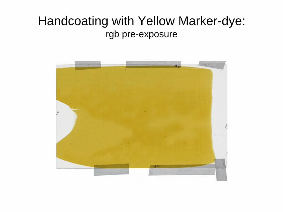
Handcoating with Yellow Marker-dye: rgb pre-exposure

Handcoating with Yellow Marker-dye: Red channel pre-exposure

Handcoating with Yellow Marker-dye: Blue channel pre-exposure

Dose/profile Before Correction

Dose/profile After Correction

Protocol for using the marker dye in EBT2
Step 1: Calibration
ODR = -log10(PVR/65535)
ODB = -log10(PVB/65535)

Dual channel dosimetry
Red channel
Composite channels
Blue channel
There‟s a better way, a much better way!
• Use all the color channels – “Multi-channel film dosimetry with non-uniformity correction”,
A. Micke, et al. submitted to Med. Physics August, 2010.

Anisotropy
Coating direction (downweb) Cross web direction
•Active material crystals are:
•Rod shaped approx. 2 μm x 15μm
•Preferentially aligned in downweb direction
(parallel to coating direction)
•Light polarizers (after exposure)

Scan Orientation and Response of EBT2
0
100
200
300
400
500
600
-0.10 0.00 0.10 0.20 0.30 0.40 0.50 0.60
Do
se
, c
Gy
Red density
Dose Response EBT2, lot# 061109
Landscapeorientation

Lateral response dependence
Menegotti et al 2008 Med Phys 35 3078-84

Lateral Response Dependence
• Why? – Light scattering? No
– Path length of rays transmitted through the active
layer? No
– Path length of rays transmitted through the CCD
filters? Yes, but minor
– Polarization of light transmitted through the film

Polarization and Radiochromic Film
• Diacetylene polymers are highly anisotropic
• Light transmitted by the polymer is polarized
– Vibrational component perpendicular to the backbone is absorbed
• If the particles in radiochromic film were randomly oriented
the transmitted light would be:
– Lower intensity (equivalent to crossed polarizers)
– Unpolarized
• However particle orientation in is induced by fluid flow in the
coating process
– Therefore the transmitted light is polarized
Note: The particles in the original radiochromic film were square in cross-section. Therefore
the particles were randomly oriented and the transmitted light was unpolarized

Crossed Polarizers
R: 0.551
G: 0.483
B: 0.702
R: 0.640
G: 0.535
B: 0.739

Optical Elements in a Flatbed Scanner

Single channel dosimetry
in extreme lateral position
0.00
0.20
0.40
0.60
0.80
1.00
1.20
1.40
1.60
1.80
2.00
0 50 100 150 200 250 300 350
Do
se,
Gy
Position, x 0.353 mm
Side scan - red channel dosimetry, nolateral correction

0.00
0.20
0.40
0.60
0.80
1.00
1.20
1.40
1.60
1.80
2.00
0 50 100 150 200 250 300 350
Do
se,
Gy
Position, x 0.353 mm
red channel dosimetry, no lateral correction
red channel dosimetry, with lateral correction
Lateral response scanner calibration

Triple channel dosimetry
in extreme lateral position
0.00
0.20
0.40
0.60
0.80
1.00
1.20
1.40
1.60
1.80
2.00
0 50 100 150 200 250 300 350
Do
se,
Gy
Position, x 0.353 mm
Side scan - red channel dosimetry, nolateral correction
side scan - 3-channel dosimetry, no lateralcorrection

Triple channel film dosimetry:
Features and advantages
Separates Dose and Dose-independent effects
– Allows compensation for film thickness variation
– Allows „smart‟ noise reduction (not yet implemented in
FilmQA Pro software)
Enable the use of full film dose sensitivity of all channels
RGB without “transition error”
Significant improvement of dose map accuracy
Allows to „sense‟ calibration errors
Attenuates the lateral response artifact

0.00
0.20
0.40
0.60
0.80
1.00
1.20
1.40
1.60
1.80
2.00
0 50 100 150 200 250 300 350
Do
se,
Gy
Position, x 0.353 mm
3-channel dosimetry with lateral correction
red channel dosimetry, no lateral correction
3-channel dosimetry, no lateral correction
red channel dosimetry, with lateral correction
Lateral response scanner calibration
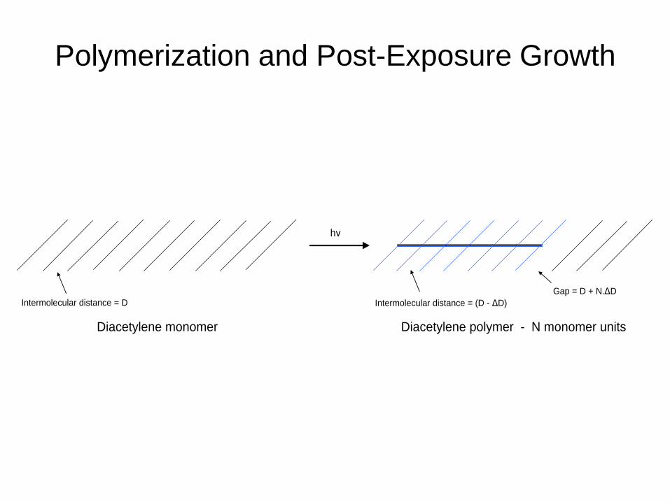
Polymerization and Post-Exposure Growth
Gap = D + N.ΔD
Intermolecular distance = (D - ΔD)
Diacetylene polymer - N monomer unitsDiacetylene monomer
Intermolecular distance = D
hν
Polymerization and Post-exposure Changes
• Polymerization starts within 100 μsec of exposure
• At low exposures (<100 Gy) polymerization proceeds as
a first order reaction for about 30 msec
• The polymer shrinks relative to the monomer
– The distance between the end of a growing chain and the next
monomer increases as polymerization increases
• Within a second the initial fast phase converts to a slow
phase where changes in absorption are proportional to
log(time)
• Protocols for using radiochromic film must
accommodate the post-exposure changes

Spectral Changes Post-exposure
0.00
0.10
0.20
0.30
0.40
0.50
0.60
0.70
0.80
0.90
1.00
610 620 630 640 650 660
Ab
so
rba
nc
e
Wavelength, nm
GAFCHROMIC EBT: Post-Exposure Growth
90 minutes
45 minutes
10 minutes
7 hours

Post-exposure Change
y = 0.0076x + 0.2991 R² = 0.9956
y = 0.0044x + 0.2446 R² = 0.9952
y = 0.0022x + 0.5024 R² = 0.9795
0.20
0.25
0.30
0.35
0.40
0.45
0.50
0.55
0.60
0.0 0.5 1.0 1.5 2.0 2.5 3.0 3.5
Den
sity
Log10(time after exposure, min)
Post-exposure change
Red
Green
Blue

Energy Independent Dose Response
0.00
0.10
0.20
0.30
0.40
0.50
0.60
0 50 100 150 200 250 300 350
Ne
t V
isu
al D
en
sit
y
Dose (cGy)
30kVp, 2mm Al
100kVp, 2mm Al
150kVp, 2mm Al
Cobalt 60

Energy Dependence of EBT2 Film
Alexandra Rink and Pamela Lindsey, AAPM Annual
Meeting, 2009
* Proportions of Cl and Br in the entire film
EBT2 Lot # Ratio OD105kVp/6MV Cl, ppm* Br, ppm*020609 1.18±0.04 1520±118 738±60
031109 0.77±0.022 1390±90 43±1
050709 1.02±0.03 1330±41 532±20

Elemental Composition and Zeff of EBT2
H Li C N O Na S Cl Br
Polyester film base* 50 1.35 36.4% 0.0% 45.5% 0.0% 18.2% 0.0% 0.0% 0.0% 0.0%
Adhesive* 25 1.2 57.1% 0.0% 33.3% 0.0% 9.5% 0.0% 0.0% 0.0% 0.0%
Active layer (assumes 7.5% moisture)** 30 1.2 58.3% 0.8% 29.6% 0.1% 10.8% 0.1% 0.0% 0.2% 0.1%
Polyester film base* 175 1.35 36.4% 0.0% 45.5% 0.0% 18.2% 0.0% 0.0% 0.0% 0.0%
Overall Composition 40.57% 0.09% 42.68% 0.01% 16.62% 0.01% 0.00% 0.02% 0.01%
* The composition of these layers is a good faith estimate based on the manufacturer's identification of the constituents. The composition should not be used as a specification.
** The composition of these layers is a good faith estimate based on the proportion of the chemical constituents. The composition should not be used as a specification.
*** The thicknesses are approximate and are not specifications.
6.64
6.26
8.27
6.64
6.78
LayerThickness***
microns
Approximate
density g/cm2
COMPOSITION (ATOM%)Zeff = [∑ αi (Zi)
a]1/a

EBT2 is Usable in Water Phantoms
0
1
2
3
4
5
6
7
8
0 4 8 12 16 20 24
Pe
ne
tra
tio
n, m
m
Time, hours
Penetration of Water into Radiochromic Film
GAFCHROMIC EBT-2
GAFCHROMIC EBT
Water front at
position 365
Edge of film at
position 388
Profile
Magnification

What can go wrong?
• Changes to the signal from the marker dye
•
• The active component changes sensitivity
• The alignment of the active component differs

Performance Issues and Corrective Actions
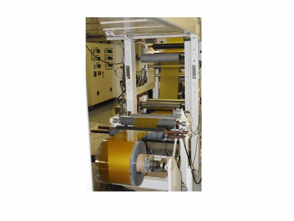
• Coating uniformity
– Installed precision coating dies (ex-Polaroid) (3/09)
– Installed direct-drive motors for web transport (3/09)
– Optimized fluid formulations and machine parameters
• Uniformity of particle alignment
– Restricted coating width to <18” (from 21½”) (6/10)
• Changes in absorbance of marker dye induced by
moisture
– Eliminated K⁺ ion (5/09)
– Adjusted marker dye and Na⁺ ion concentrations (5/10)
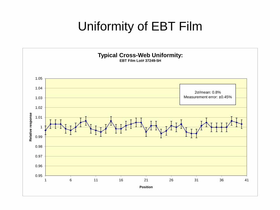
Uniformity of EBT Film
0.95
0.96
0.97
0.98
0.99
1
1.01
1.02
1.03
1.04
1.05
1 6 11 16 21 26 31 36 41
Rela
tive r
esp
on
se
Position
Typical Cross-Web Uniformity: EBT Film Lot# 37249-5H
2σ/mean: 0.8%
Measurement error: ±0.45%
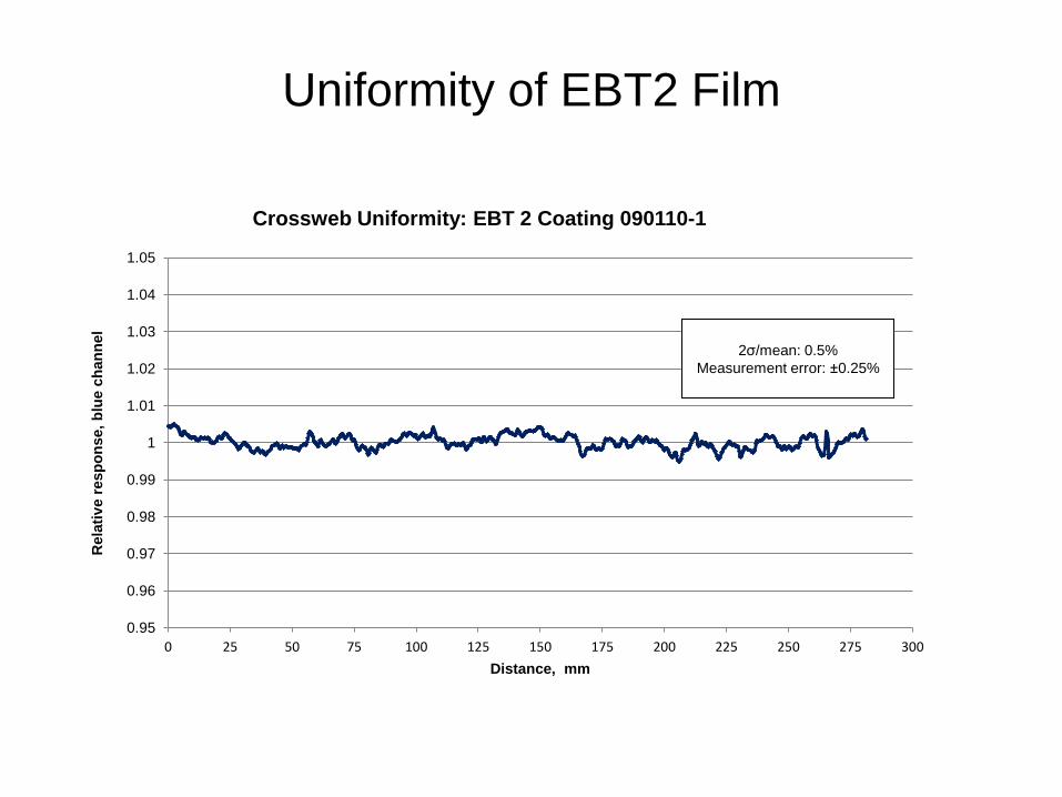
Uniformity of EBT2 Film
0.95
0.96
0.97
0.98
0.99
1
1.01
1.02
1.03
1.04
1.05
0 25 50 75 100 125 150 175 200 225 250 275 300
Rela
tiv
e r
esp
on
se,
blu
e c
han
nel
Distance, mm
Crossweb Uniformity: EBT 2 Coating 090110-1
2σ/mean: 0.5%
Measurement error: ±0.25%

Crossweb Profiles Particle Alignment is not Uniform
0.6
0.65
0.7
0.75
0.8
0.85
0.9
0.95
1
1.05
1.1
0 2 4 6 8 10 12 14 16 18 20 22
Den
sit
y
Crossweb position, inches
Red Blue

Is there an EBT3?

EBT2 Improvement Projects
• Change to a pigment dye
– Greater chemical stability, will not diffuse
• Water lamination and symmetric structure
– Re-create the structure used in the original EBT film
• Using a polyester substrate with microscopic silica on
the surface
– Eliminates Newton‟s Rings
• Cross lamination
• Energy independence
– Making the film energy independent from 10 kV into the MV
range
• Enhancing scanner response with selected optical filters

Hypothesis
• We could approximate the random orientation
condition by crossing two pieces of film
• This approaches the state of crossed polarizers
– Perfect polarizer transmits 50% of incident
unpolarized light
– Two perfect polarizers aligned transmit 50% of
incident unpolarized light
– Two perfect polarizers crossed transmit no light

Polarization in Radiochromic Film
• Crystal alignment is the source of polarization
effects in EBT2
• Particle alignment is very difficult to control
– In EBT2 there is only a partial (preferential) alignment
• Would be easier to deal with if: – Alignment was 100% perfect
– Alignment was 100% “imperfect”
• # crystals/unit volume large and crystals randomly oriented

In-line lamination

Cross lamination
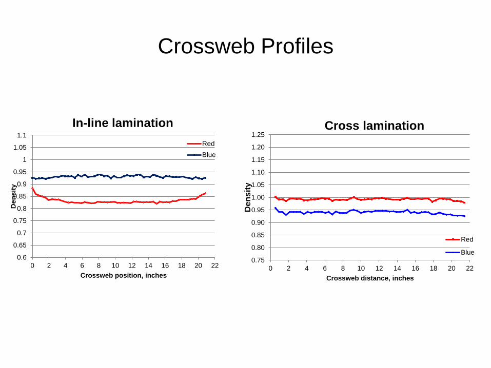
Crossweb Profiles
0.75
0.80
0.85
0.90
0.95
1.00
1.05
1.10
1.15
1.20
1.25
0 2 4 6 8 10 12 14 16 18 20 22
Den
sit
y
Crossweb distance, inches
Cross lamination
Red
Blue0.6
0.65
0.7
0.75
0.8
0.85
0.9
0.95
1
1.05
1.1
0 2 4 6 8 10 12 14 16 18 20 22
Den
sit
y
Crossweb position, inches
In-line lamination
Red
Blue

Advantages of Cross-lamination
• Improves sensitivity/contrast at doses >50 cGy
• Assists the proper function of the marker dye
• Eliminates orientation effects on the scanner
• Reduces noise level

0
0.1
0.2
0.3
0.4
0.5
0.6
0.7
0 100 200 300 400 500 600 700 800
Den
sit
y
Dose, cGy
In-line, red
In-line, green
In-line, blue
Cross-laminate, red
Cross laminate, green
Cross-laminate, blue

Cross-lamination: No orientation dependence
@ 0 degrees @ 90 degrees

12000
17000
22000
27000
32000
37000
42000
47000
52000
0 100 200 300 400 500 600 700 800
Cross-laminated EBT2 : Red channel response
Original orientation
Flipped
Turned 90 degrees
Turned 45 degrees
Cross-lamination: No orientation dependence
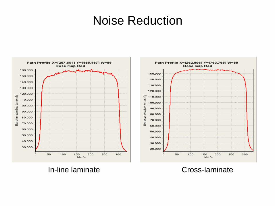
Noise Reduction
In-line laminate Cross-laminate


Related Documents


![Principal Component Analysis of EBT2 Radiochromic Film for ... · A radiochromic film that incorporates a yellow dye in its sensitive layer [Gafchromic EBT2, Ashland, Inc.] is commercially](https://static.cupdf.com/doc/110x72/5fd0e39e66d6d301e55dcd76/principal-component-analysis-of-ebt2-radiochromic-film-for-a-radiochromic-film.jpg)