Report No.: RJ180409D11 Page No. 1 / 114 Report Format Version: 6.1.1 Radio Test Report Report No.: RJ180409D11 Test Model: DrivePro 550 Received Date: Apr. 9, 2018 Test Date: May 15, 2018 Issued Date: May 16, 2018 Applicant: Transcend Information Inc. Address: No. 70, Xing Zhong Rd., NeiHu Dist., Taipei, Taiwan Issued By: Bureau Veritas Consumer Products Services (H.K.) Ltd., Taoyuan Branch Lab Address: No. 47-2, 14th Ling, Chia Pau Vil., Lin Kou Dist., New Taipei City, Taiwan (R.O.C.) This report is for your exclusive use. Any copying or replication of this report to or for any other person or entity, or use of our name or trademark, is permitted only with our prior written permission. This report sets forth our findings solely with respect to the test samples identified herein. The results set forth in this report are not indicative or representative of the quality or characteristics of the lot from which a test sample was taken or any similar or identical product unless specifically and expressly noted. Our report includes all of the tests requested by you and the results thereof based upon the information that you provided to us. You have 60 days from date of issuance of this report to notify us of any material error or omission caused by our negligence, provided, however, that such notice shall be in writing and shall specifically address the issue you wish to raise. A failure to raise such issue within the prescribed time shall constitute your unqualified acceptance of the completeness of this report, the tests conducted and the correctness of the report contents. Unless specific mention, the uncertainty of measurement has been explicitly taken into account to declare the compliance or non-compliance to the specification. The report must not be used by the client to claim product certification, approval, or endorsement by TAF or any government agencies.

Welcome message from author
This document is posted to help you gain knowledge. Please leave a comment to let me know what you think about it! Share it to your friends and learn new things together.
Transcript
Report No.: RJ180409D11 Page No. 1 / 114 Report Format Version: 6.1.1
Radio Test Report
Report No.: RJ180409D11
Test Model: DrivePro 550
Received Date: Apr. 9, 2018
Test Date: May 15, 2018
Issued Date: May 16, 2018
Applicant: Transcend Information Inc.
Address: No. 70, Xing Zhong Rd., NeiHu Dist., Taipei, Taiwan
Issued By: Bureau Veritas Consumer Products Services (H.K.) Ltd., Taoyuan Branch
Lab Address: No. 47-2, 14th Ling, Chia Pau Vil., Lin Kou Dist., New Taipei City, Taiwan (R.O.C.)
This report is for your exclusive use. Any copying or replication of this report to or for any other person or entity, or use of our name or trademark, is permitted only with our prior written permission. This report sets forth our findings solely with respect to the test samples identified herein. The results set forth in this report are not indicative or representative of the quality or characteristics of the lot from which a test sample was taken or any similar or identical product unless specifically and expressly noted. Our report includes all of the tests requested by you and the results thereof based upon the information that you provided to us. You have 60 days from date of issuance of this report to notify us of any material error or omission caused by our negligence, provided, however, that such notice shall be in writing and shall specifically address the issue you wish to raise. A failure to raise such issue within the prescribed time shall constitute your unqualified acceptance of the completeness of this report, the tests conducted and the correctness of the report contents. Unless specific mention, the uncertainty of measurement has been explicitly taken into account to declare the compliance or non-compliance to the specification. The report must not be used by the client to claim product certification, approval, or endorsement by TAF or any government agencies.
Report No.: RJ180409D11 Page No. 2 / 114 Report Format Version: 6.1.1
Table of Contents
Release Control Record .................................................................................................................................... 4
1 Certificate of Conformity ......................................................................................................................... 5
2 Summary of Test Results ........................................................................................................................ 6
2.1 Test Instruments .................................................................................................................................. 7 2.2 Measurement Uncertainty ................................................................................................................... 7 2.3 Modification Record ............................................................................................................................ 7
3 General Information ................................................................................................................................ 8
3.1 General Description of EUT ................................................................................................................ 8 3.2 Description of Test Modes ................................................................................................................. 10 3.3 Test Conditions ................................................................................................................................... 11 3.4 Assembly ............................................................................................................................................ 11 3.5 Test Operating Setup ......................................................................................................................... 11 3.6 Antenna Specifications ...................................................................................................................... 12 3.6.1 Antenna Gain ..................................................................................................................................... 12 3.6.2 Antenna Pattern ................................................................................................................................. 12
4 Test Results .......................................................................................................................................... 13
4.1 Frequency Tolerance Measurement .................................................................................................. 13 4.1.1 Limits of Frequency Tolerance Measurement ................................................................................... 13 4.1.2 Test Setup .......................................................................................................................................... 13 4.1.3 Test Results ....................................................................................................................................... 14 4.2 Occupied Bandwidth Measurement (99% power bandwidth) ........................................................... 15 4.2.1 Limits of Occupied Bandwidth Measurement .................................................................................... 15 4.2.2 Test Setup .......................................................................................................................................... 15 4.2.3 Test Results ....................................................................................................................................... 16 4.3 Spreading Bandwidth Measurement (90% power bandwidth) .......................................................... 28 4.3.1 Limits of Spreading Bandwidth and Spreading Factor Measurement ............................................... 28 4.3.2 Test Setup .......................................................................................................................................... 28 4.3.3 Test Results ....................................................................................................................................... 29 4.4 Spurious Emissions for Transmitter Measurement ........................................................................... 50 4.4.1 Limits of Spurious Emissions ............................................................................................................. 50 4.4.2 Test Setup .......................................................................................................................................... 50 4.4.3 Test Results ....................................................................................................................................... 51 4.5 Antenna Power Measurement ........................................................................................................... 95 4.5.1 Limits of Antenna Power .................................................................................................................... 95 4.5.2 Test Setup .......................................................................................................................................... 95 4.5.3 Test Results ....................................................................................................................................... 96 4.6 Spurious Emissions for Receiver .................................................................................................... 100 4.6.1 Limits of Spurious Emissions For Receiver ..................................................................................... 100 4.6.2 Test Setup ........................................................................................................................................ 100 4.6.3 Test Result ....................................................................................................................................... 101 4.7 Carrier Sense Capability ................................................................................................................. 109 4.7.1 Measuring System Block Diagram .................................................................................................. 109 4.7.2 Measuring Operation Procedures ................................................................................................... 109 4.7.3 Level of the Ambient Carrier ............................................................................................................. 110 4.7.4 Test Result ........................................................................................................................................ 110 4.8 Interference Prevention Function ..................................................................................................... 111
Report No.: RJ180409D11 Page No. 3 / 114 Report Format Version: 6.1.1
4.8.1 Limits of Interference Prevention Function ....................................................................................... 111 4.8.2 Test Setup ......................................................................................................................................... 111 4.8.3 Test Results ...................................................................................................................................... 111 4.9 Number of Carriers within 1 MHz Bandwidth in OFDM .................................................................... 112 4.9.1 Limit of Number of Cariers ............................................................................................................... 112 4.9.2 Test Setup ......................................................................................................................................... 112 4.9.3 Test Result ........................................................................................................................................ 112
5 Photographs of the Test Configuration ................................................................................................ 113
Appendix - Information on the Testing Laboratories ....................................................................................... 114
Report No.: RJ180409D11 Page No. 4 / 114 Report Format Version: 6.1.1
Release Control Record
Issue No. Description Date Issued
RJ180409D11 Original release. May 16, 2018
Report No.: RJ180409D11 Page No. 5 / 114 Report Format Version: 6.1.1
1 Certificate of Conformity
Product: Dashcam
Brand: Transcend
Test Model: DrivePro 550
Sample Status: Engineering sample
Applicant: Transcend Information Inc.
Test Date: May 15, 2018
Standards: ARIB STD-T66 (V3.7), MIC notice 88 Appendix 43
The above equipment has been tested by Bureau Veritas Consumer Products Services (H.K.) Ltd.,
Taoyuan Branch, and found compliance with the requirement of the above standards. The test record, data
evaluation & Equipment Under Test (EUT) configurations represented herein are true and accurate accounts
of the measurements of the sample’s RF characteristics under the conditions specified in this report.
Prepared by :
, Date: May 16, 2018
Jessica Cheng / Senior Specialist
Approved by
:
, Date: May 16, 2018
Rex Lai / Associate Technical Manager
Report No.: RJ180409D11 Page No. 6 / 114 Report Format Version: 6.1.1
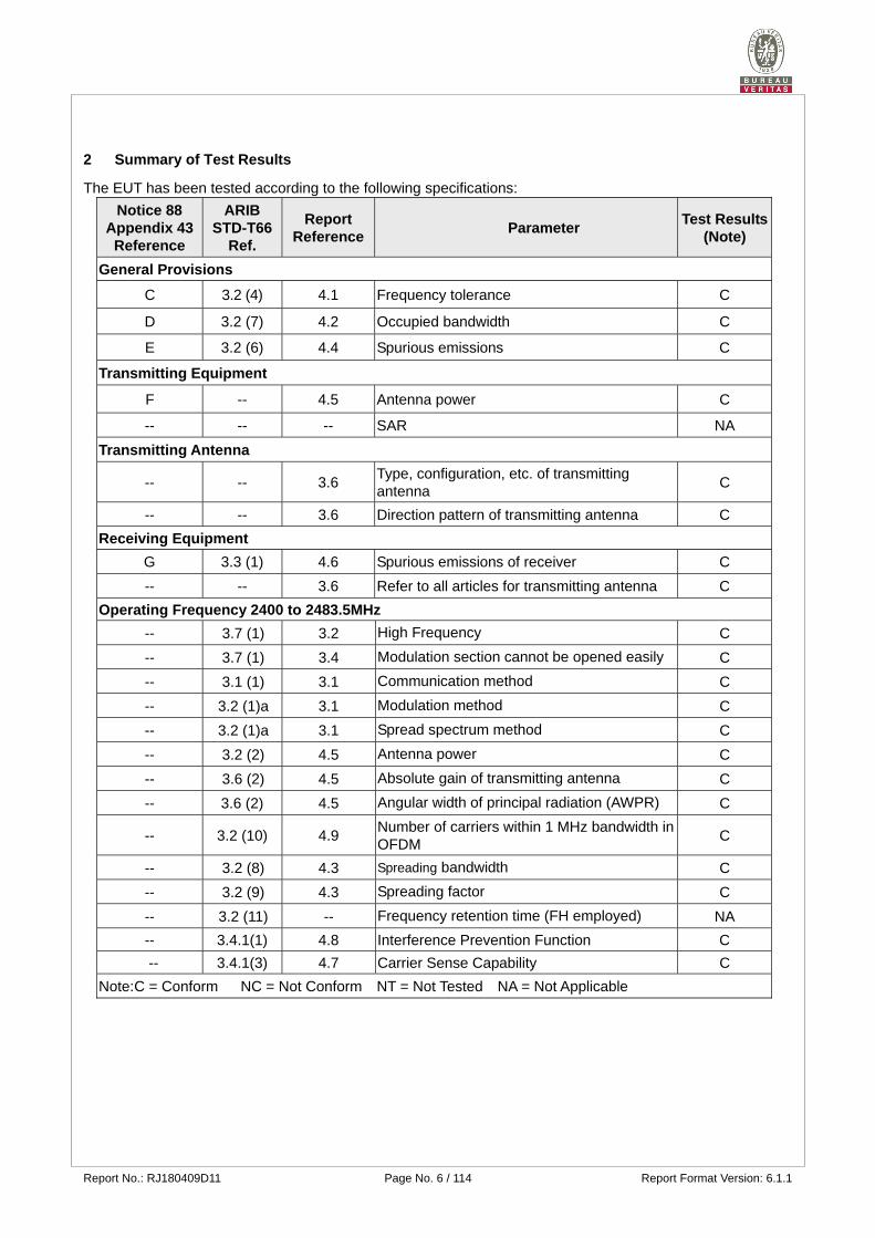
2 Summary of Test Results
The EUT has been tested according to the following specifications:
Notice 88 Appendix 43 Reference
ARIB STD-T66
Ref.
Report Reference
Parameter Test Results
(Note)
General Provisions
C 3.2 (4) 4.1 Frequency tolerance C
D 3.2 (7) 4.2 Occupied bandwidth C
E 3.2 (6) 4.4 Spurious emissions C
Transmitting Equipment
F -- 4.5 Antenna power C
-- -- -- SAR NA
Transmitting Antenna
-- -- 3.6 Type, configuration, etc. of transmitting antenna
C
-- -- 3.6 Direction pattern of transmitting antenna C
Receiving Equipment
G 3.3 (1) 4.6 Spurious emissions of receiver C
-- -- 3.6 Refer to all articles for transmitting antenna C
Operating Frequency 2400 to 2483.5MHz
-- 3.7 (1) 3.2 High Frequency C
-- 3.7 (1) 3.4 Modulation section cannot be opened easily C
-- 3.1 (1) 3.1 Communication method C
-- 3.2 (1)a 3.1 Modulation method C
-- 3.2 (1)a 3.1 Spread spectrum method C
-- 3.2 (2) 4.5 Antenna power C
-- 3.6 (2) 4.5 Absolute gain of transmitting antenna C
-- 3.6 (2) 4.5 Angular width of principal radiation (AWPR) C
-- 3.2 (10) 4.9 Number of carriers within 1 MHz bandwidth in OFDM
C
-- 3.2 (8) 4.3 Spreading bandwidth C
-- 3.2 (9) 4.3 Spreading factor C
-- 3.2 (11) -- Frequency retention time (FH employed) NA
-- 3.4.1(1) 4.8 Interference Prevention Function C
-- 3.4.1(3) 4.7 Carrier Sense Capability C
Note: C = Conform NC = Not Conform NT = Not Tested NA = Not Applicable
Report No.: RJ180409D11 Page No. 7 / 114 Report Format Version: 6.1.1
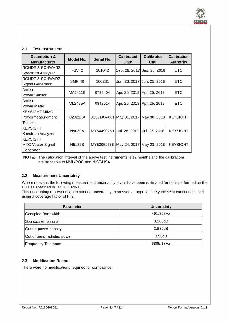
2.1 Test Instruments
Description &
Manufacturer Model No. Serial No.
Calibrated
Date
Calibrated
Until
Calibration
Authority
ROHDE & SCHWARZ
Spectrum Analyzer FSV40 101042 Sep. 29, 2017 Sep. 28, 2018 ETC
ROHDE & SCHWARZ
Signal Generator SMR 40 100231 Jun. 26, 2017 Jun. 25, 2018 ETC
Anritsu
Power Sensor MA2411B 0738404 Apr. 26, 2018 Apr. 25, 2019 ETC
Anritsu
Power Meter ML2495A 0842014 Apr. 26, 2018 Apr. 25, 2019 ETC
KEYSIGHT MIMO
Powermeasurement
Test set
U2021XA U2021XA-001 May 31, 2017 May 30, 2018 KEYSIGHT
KEYSIGHT
Spectrum Analyzer N9030A MY54490260 Jul. 26, 2017 Jul. 25, 2018 KEYSIGHT
KEYSIGHT
MXG Vector Signal
Generator
N5182B MY53052658 May 24, 2017 May 23, 2018 KEYSIGHT
NOTE:. The calibration interval of the above test instruments is 12 months and the calibrations
are traceable to NML/ROC and NIST/USA.
2.2 Measurement Uncertainty
Where relevant, the following measurement uncertainty levels have been estimated for tests performed on the EUT as specified in TR 100 028-1. This uncertainty represents an expanded uncertainty expressed at approximately the 95% confidence level using a coverage factor of k=2.
Parameter Uncertainty
Occupied Bandwidth 491.896Hz
Spurious emissions 3.508dB
Output power density 2.889dB
Out of band radiated power 3.93dB
Frequency Tolerance 6805.18Hz
2.3 Modification Record
There were no modifications required for compliance.
Report No.: RJ180409D11 Page No. 8 / 114 Report Format Version: 6.1.1
3 General Information
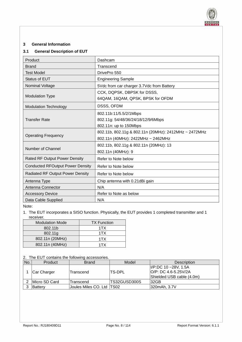
3.1 General Description of EUT
Product Dashcam
Brand Transcend
Test Model DrivePro 550
Status of EUT Engineering Sample
Nominal Voltage 5Vdc from car charger 3.7Vdc from Battery
Modulation Type CCK, DQPSK, DBPSK for DSSS,
64QAM, 16QAM, QPSK, BPSK for OFDM
Modulation Technology DSSS, OFDM
Transfer Rate
802.11b:11/5.5/2/1Mbps
802.11g: 54/48/36/24/18/12/9/6Mbps
802.11n: up to 150Mbps
Operating Frequency 802.11b, 802.11g & 802.11n (20MHz): 2412MHz ~ 2472MHz
802.11n (40MHz): 2422MHz ~ 2462MHz
Number of Channel 802.11b, 802.11g & 802.11n (20MHz): 13
802.11n (40MHz): 9
Rated RF Output Power Density Refer to Note below
Conducted RFOutput Power Density Refer to Note below
Radiated RF Output Power Density Refer to Note below
Antenna Type Chip antenna with 0.21dBi gain
Antenna Connector N/A
Accessory Device Refer to Note as below
Data Cable Supplied N/A
Note:
1. The EUT incorporates a SISO function. Physically, the EUT provides 1 completed transmitter and 1 receiver.
Modulation Mode TX Function 802.11b 1TX 802.11g 1TX
802.11n (20MHz) 1TX 802.11n (40MHz) 1TX
2. The EUT contains the following accessories. No. Product Brand Model Description
1 Car Charger Transcend TS-DPL I/P:DC 10 ~28V, 1.5A O/P: DC 4.6-5.25V/2A Shielded USB cable (4.0m)
2 Micro SD Card Transcend TS32GUSD300S 32GB 3 Battery Joules Miles CO. Ltd TS02 320mAh, 3.7V
Report No.: RJ180409D11 Page No. 9 / 114 Report Format Version: 6.1.1
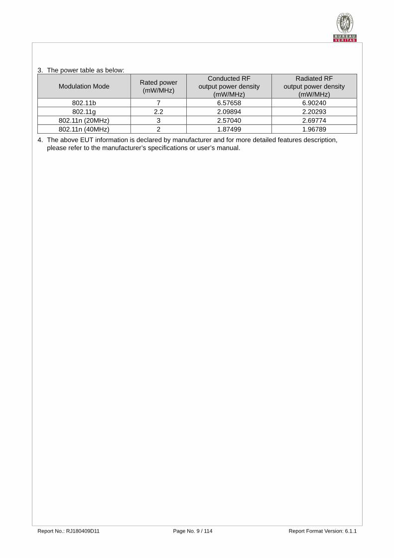
3. The power table as below:
Modulation Mode Rated power (mW/MHz)
Conducted RF output power density
(mW/MHz)
Radiated RF output power density
(mW/MHz) 802.11b 7 6.57658 6.90240 802.11g 2.2 2.09894 2.20293
802.11n (20MHz) 3 2.57040 2.69774 802.11n (40MHz) 2 1.87499 1.96789
4. The above EUT information is declared by manufacturer and for more detailed features description, please refer to the manufacturer’s specifications or user’s manual.
Report No.: RJ180409D11 Page No. 10 / 114 Report Format Version: 6.1.1
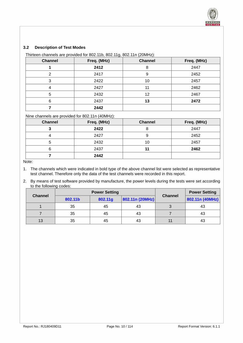
3.2 Description of Test Modes
Thirteen channels are provided for 802.11b, 802.11g, 802.11n (20MHz):
Channel Freq. (MHz) Channel Freq. (MHz)
1 2412 8 2447
2 2417 9 2452
3 2422 10 2457
4 2427 11 2462
5 2432 12 2467
6 2437 13 2472
7 2442
Nine channels are provided for 802.11n (40MHz):
Channel Freq. (MHz) Channel Freq. (MHz)
3 2422 8 2447
4 2427 9 2452
5 2432 10 2457
6 2437 11 2462
7 2442
Note:
1. The channels which were indicated in bold type of the above channel list were selected as representative test channel. Therefore only the data of the test channels were recorded in this report.
2. By means of test software provided by manufacture, the power levels during the tests were set according to the following codes:
Channel Power Setting
Channel Power Setting
802.11b 802.11g 802.11n (20MHz) 802.11n (40MHz)
1 35 45 43 3 43
7 35 45 43 7 43
13 35 45 43 11 43
Report No.: RJ180409D11 Page No. 11 / 114 Report Format Version: 6.1.1
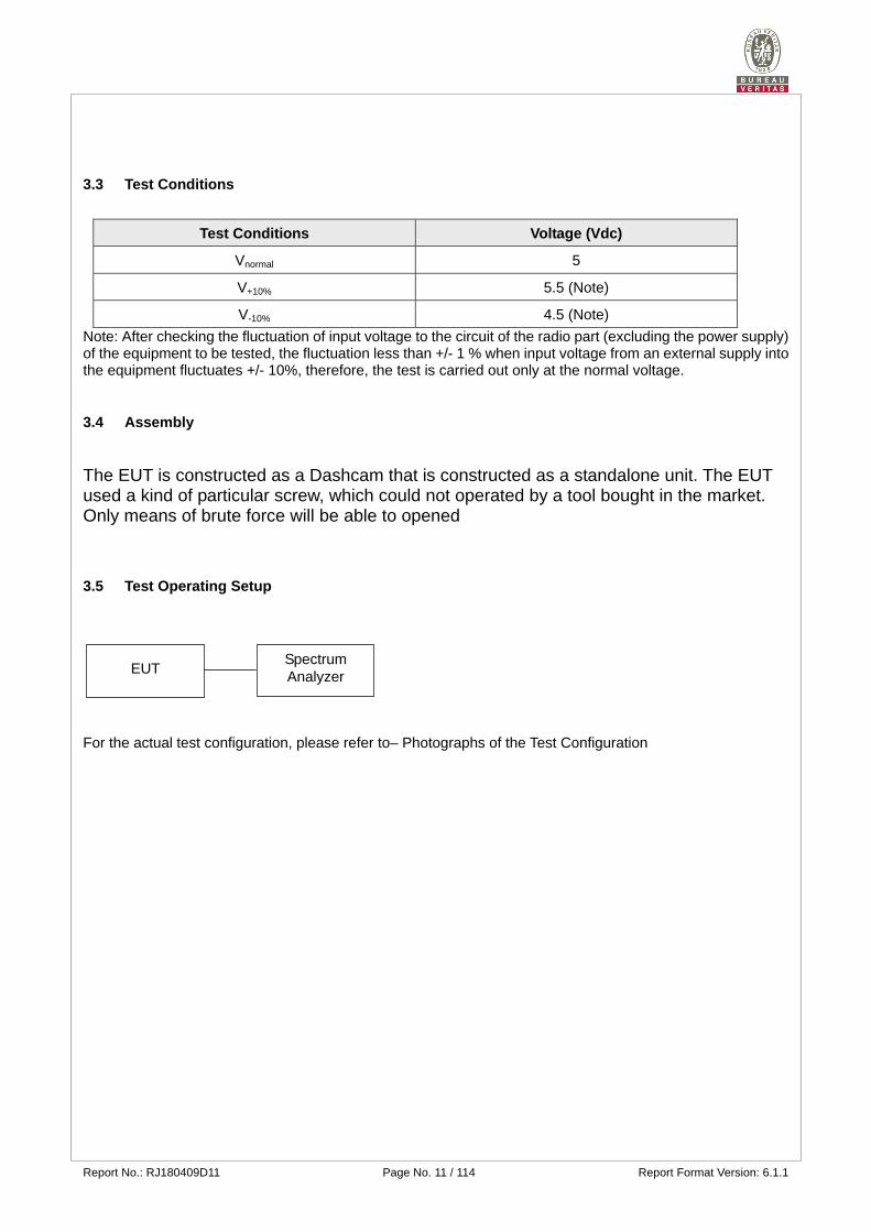
3.3 Test Conditions
Test Conditions Voltage (Vdc)
Vnormal 5
V+10% 5.5 (Note)
V-10% 4.5 (Note)
Note: After checking the fluctuation of input voltage to the circuit of the radio part (excluding the power supply) of the equipment to be tested, the fluctuation less than +/- 1 % when input voltage from an external supply into the equipment fluctuates +/- 10%, therefore, the test is carried out only at the normal voltage.
3.4 Assembly The EUT is constructed as a Dashcam that is constructed as a standalone unit. The EUT used a kind of particular screw, which could not operated by a tool bought in the market. Only means of brute force will be able to opened
3.5 Test Operating Setup
For the actual test configuration, please refer to– Photographs of the Test Configuration
Spectrum Analyzer EUT
Report No.: RJ180409D11 Page No. 12 / 114 Report Format Version: 6.1.1
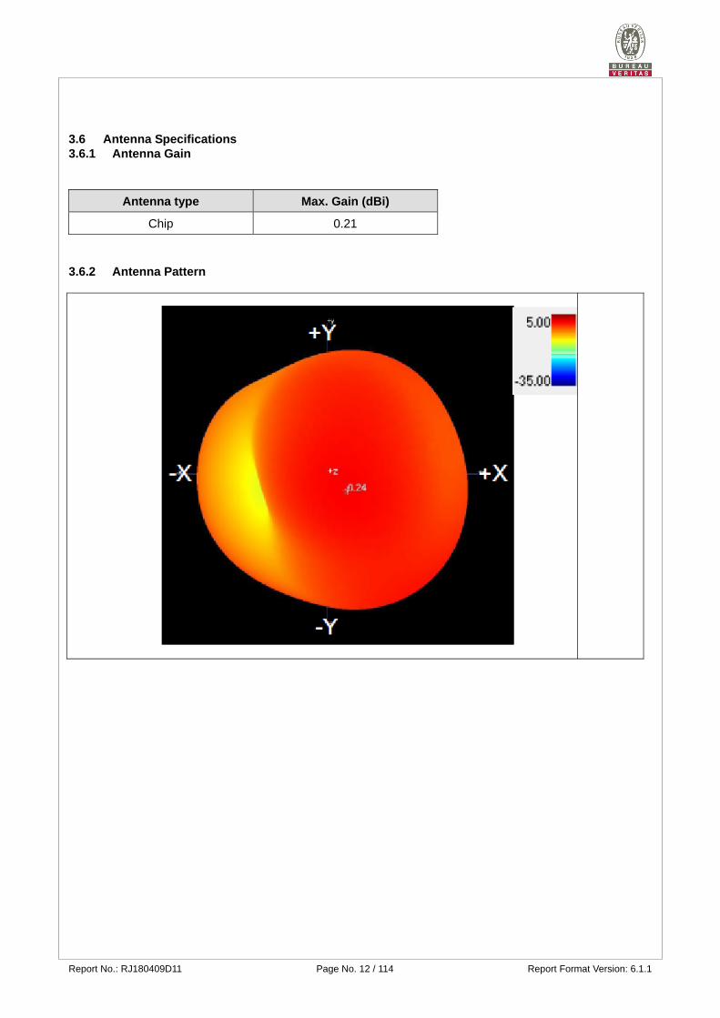
3.6 Antenna Specifications 3.6.1 Antenna Gain
Antenna type Max. Gain (dBi)
Chip 0.21
3.6.2 Antenna Pattern
Report No.: RJ180409D11 Page No. 13 / 114 Report Format Version: 6.1.1
4 Test Results
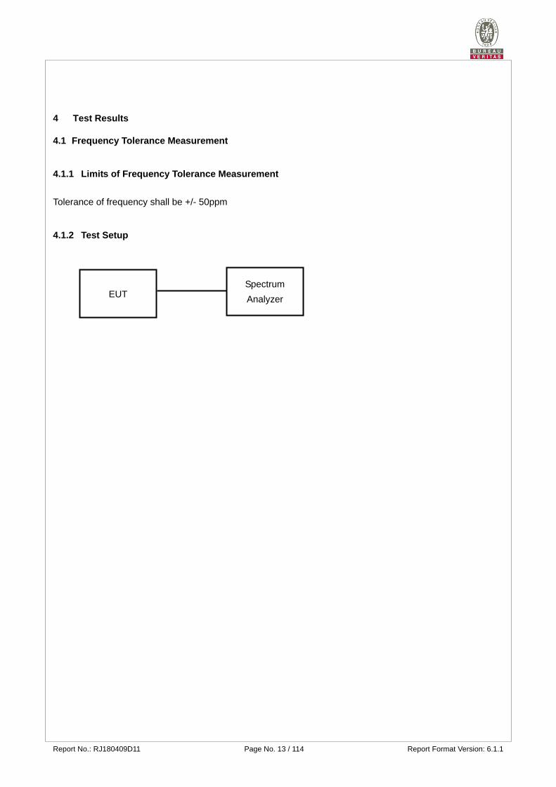
4.1 Frequency Tolerance Measurement
4.1.1 Limits of Frequency Tolerance Measurement
Tolerance of frequency shall be +/- 50ppm
4.1.2 Test Setup
EUT Spectrum
Analyzer
Report No.: RJ180409D11 Page No. 14 / 114 Report Format Version: 6.1.1
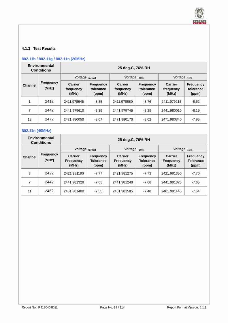
4.1.3 Test Results
802.11b / 802.11g / 802.11n (20MHz)
Environmental Conditions
25 deg.C, 76% RH
Channel Frequency
(MHz)
Voltage normal Voltage +10% Voltage -10%
Carrier frequency
(MHz)
Frequency tolerance
(ppm)
Carrier frequency
(MHz)
Frequency tolerance
(ppm)
Carrier frequency
(MHz)
Frequency tolerance
(ppm)
1 2412 2411.978645 -8.85 2411.978880 -8.76 2411.979215 -8.62
7 2442 2441.979610 -8.35 2441.979745 -8.29 2441.980010 -8.19
13 2472 2471.980050 -8.07 2471.980170 -8.02 2471.980340 -7.95
802.11n (40MHz)
Environmental Conditions
25 deg.C, 76% RH
Channel Frequency
(MHz)
Voltage normal Voltage +10% Voltage -10%
Carrier Frequency
(MHz)
Frequency Tolerance
(ppm)
Carrier Frequency
(MHz)
Frequency Tolerance
(ppm)
Carrier Frequency
(MHz)
Frequency Tolerance
(ppm)
3 2422 2421.981180 -7.77 2421.981275 -7.73 2421.981350 -7.70
7 2442 2441.981320 -7.65 2441.981240 -7.68 2441.981325 -7.65
11 2462 2461.981400 -7.55 2461.981585 -7.48 2461.981445 -7.54
Report No.: RJ180409D11 Page No. 15 / 114 Report Format Version: 6.1.1
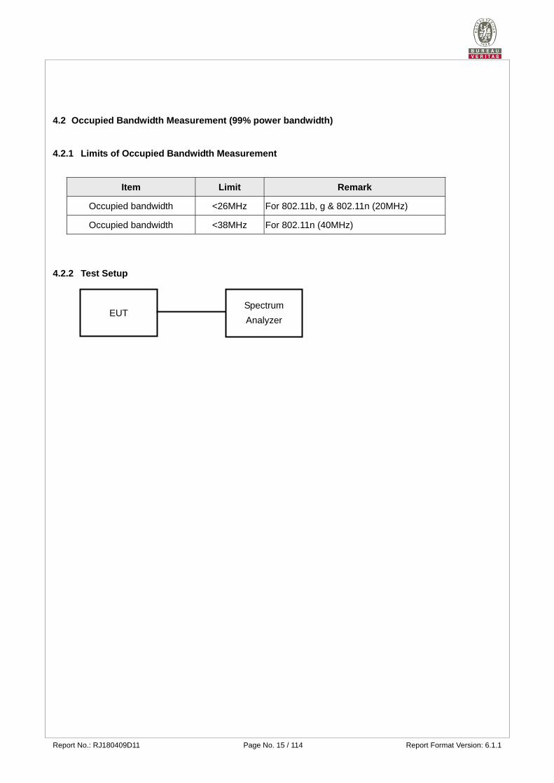
4.2 Occupied Bandwidth Measurement (99% power bandwidth)
4.2.1 Limits of Occupied Bandwidth Measurement
Item Limit Remark
Occupied bandwidth <26MHz For 802.11b, g & 802.11n (20MHz)
Occupied bandwidth <38MHz For 802.11n (40MHz)
4.2.2 Test Setup
EUT Spectrum
Analyzer
Report No.: RJ180409D11 Page No. 16 / 114 Report Format Version: 6.1.1
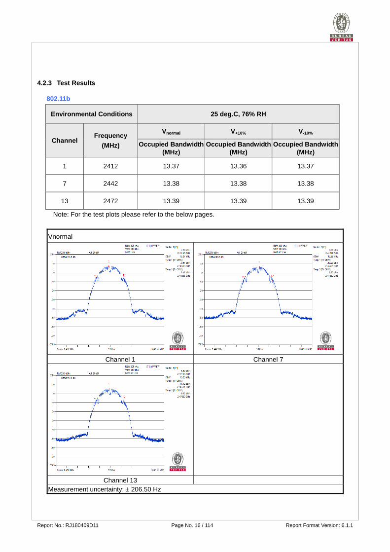
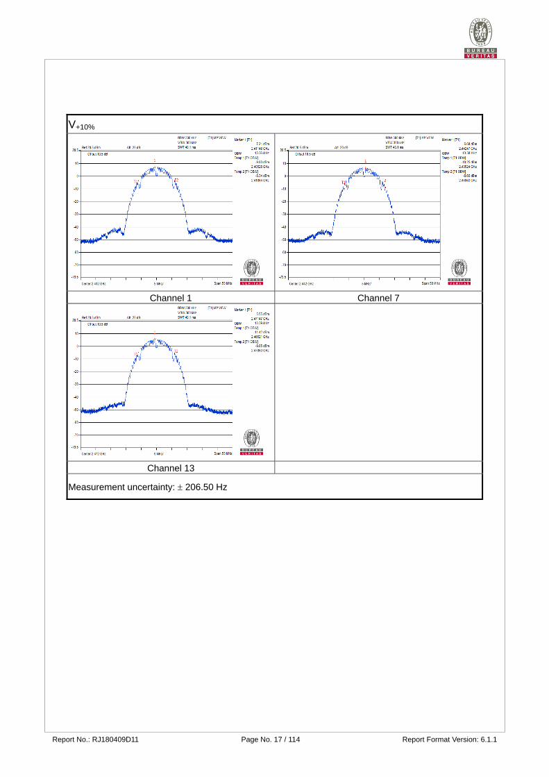
4.2.3 Test Results
802.11b
Environmental Conditions 25 deg.C, 76% RH
Channel Frequency
(MHz)
Vnormal V+10% V-10%
Occupied Bandwidth (MHz)
Occupied Bandwidth (MHz)
Occupied Bandwidth (MHz)
1 2412 13.37 13.36 13.37
7 2442 13.38 13.38 13.38
13 2472 13.39 13.39 13.39
Note: For the test plots please refer to the below pages.
Vnormal
Channel 1 Channel 7
Channel 13 Measurement uncertainty: 206.50 Hz
Report No.: RJ180409D11 Page No. 17 / 114 Report Format Version: 6.1.1
V+10%
Channel 1 Channel 7
Channel 13
Measurement uncertainty: 206.50 Hz

Report No.: RJ180409D11 Page No. 18 / 114 Report Format Version: 6.1.1
V-10%
Channel 1 Channel 7
Channel 13
Measurement uncertainty: 206.50 Hz
Report No.: RJ180409D11 Page No. 19 / 114 Report Format Version: 6.1.1
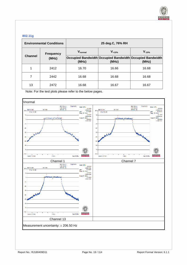
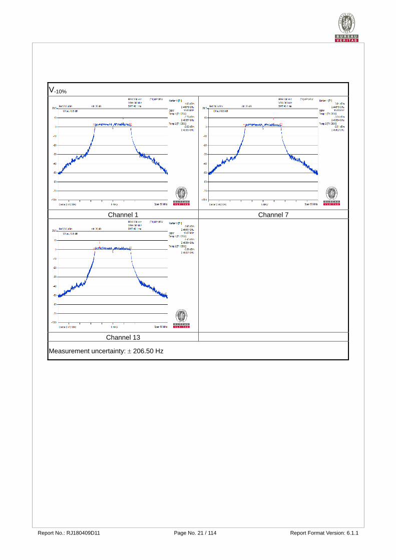
802.11g
Environmental Conditions 25 deg.C, 76% RH
Channel Frequency
(MHz)
Vnormal V+10% V-10%
Occupied Bandwidth (MHz)
Occupied Bandwidth (MHz)
Occupied Bandwidth (MHz)
1 2412 16.70 16.66 16.68
7 2442 16.68 16.68 16.68
13 2472 16.68 16.67 16.67
Note: For the test plots please refer to the below pages.
Vnormal
Channel 1 Channel 7
Channel 13
Measurement uncertainty: 206.50 Hz

Report No.: RJ180409D11 Page No. 20 / 114 Report Format Version: 6.1.1
V+10%
Channel 1 Channel 7
Channel 13
Measurement uncertainty: 206.50 Hz
Report No.: RJ180409D11 Page No. 21 / 114 Report Format Version: 6.1.1
V-10%
Channel 1 Channel 7
Channel 13
Measurement uncertainty: 206.50 Hz
Report No.: RJ180409D11 Page No. 22 / 114 Report Format Version: 6.1.1
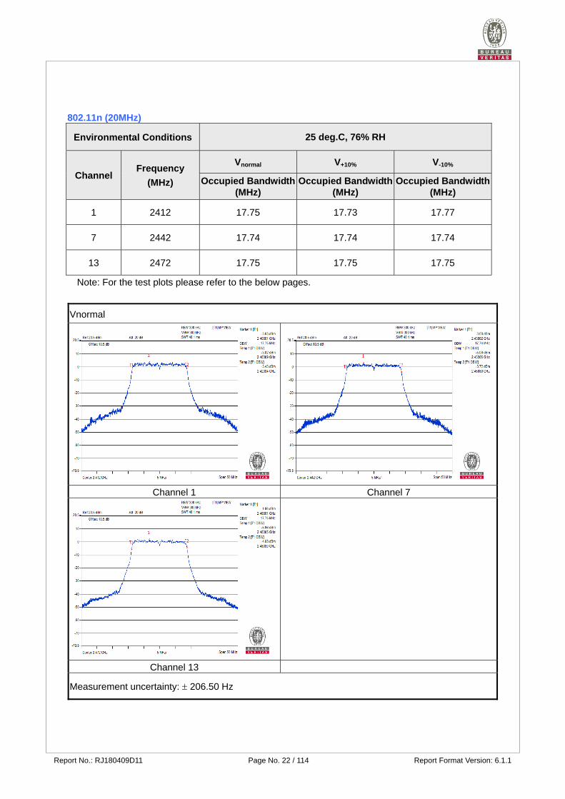
802.11n (20MHz)
Environmental Conditions 25 deg.C, 76% RH
Channel Frequency
(MHz)
Vnormal V+10% V-10%
Occupied Bandwidth (MHz)
Occupied Bandwidth (MHz)
Occupied Bandwidth (MHz)
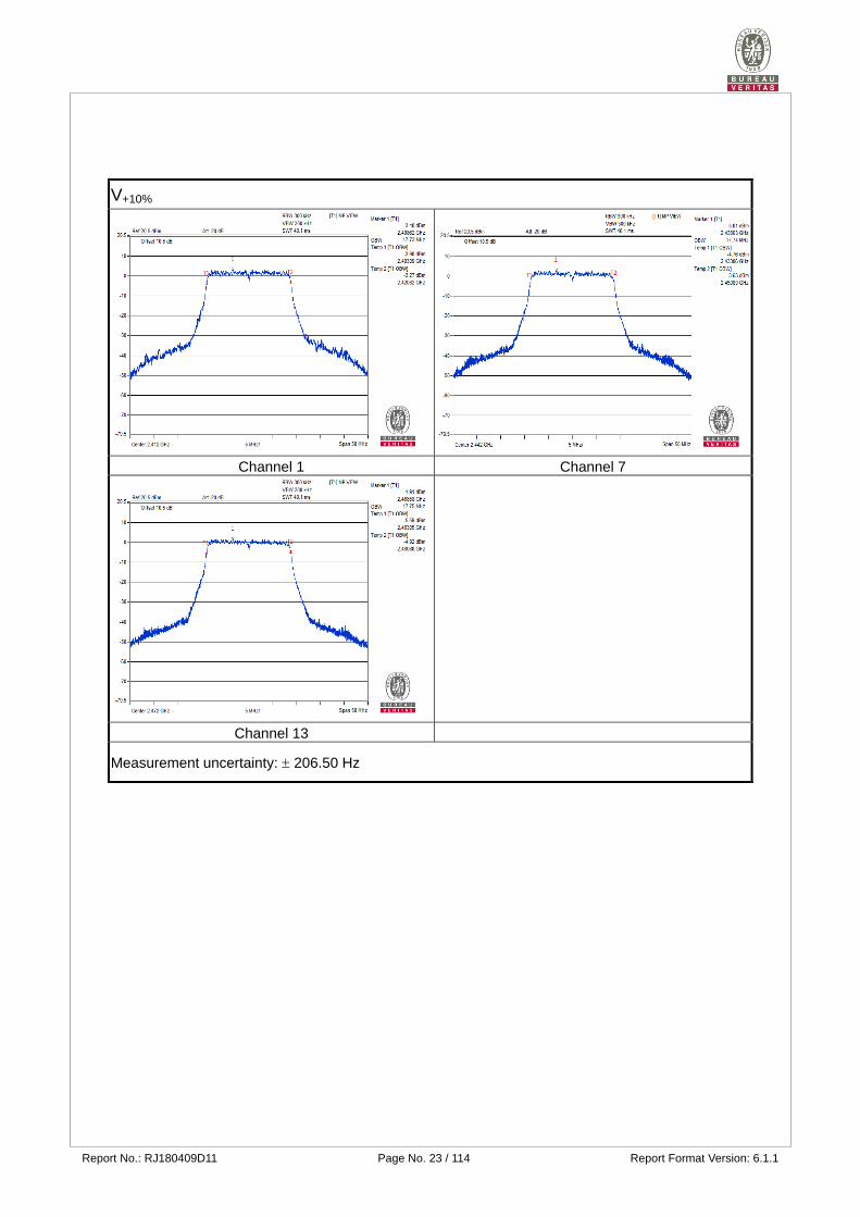
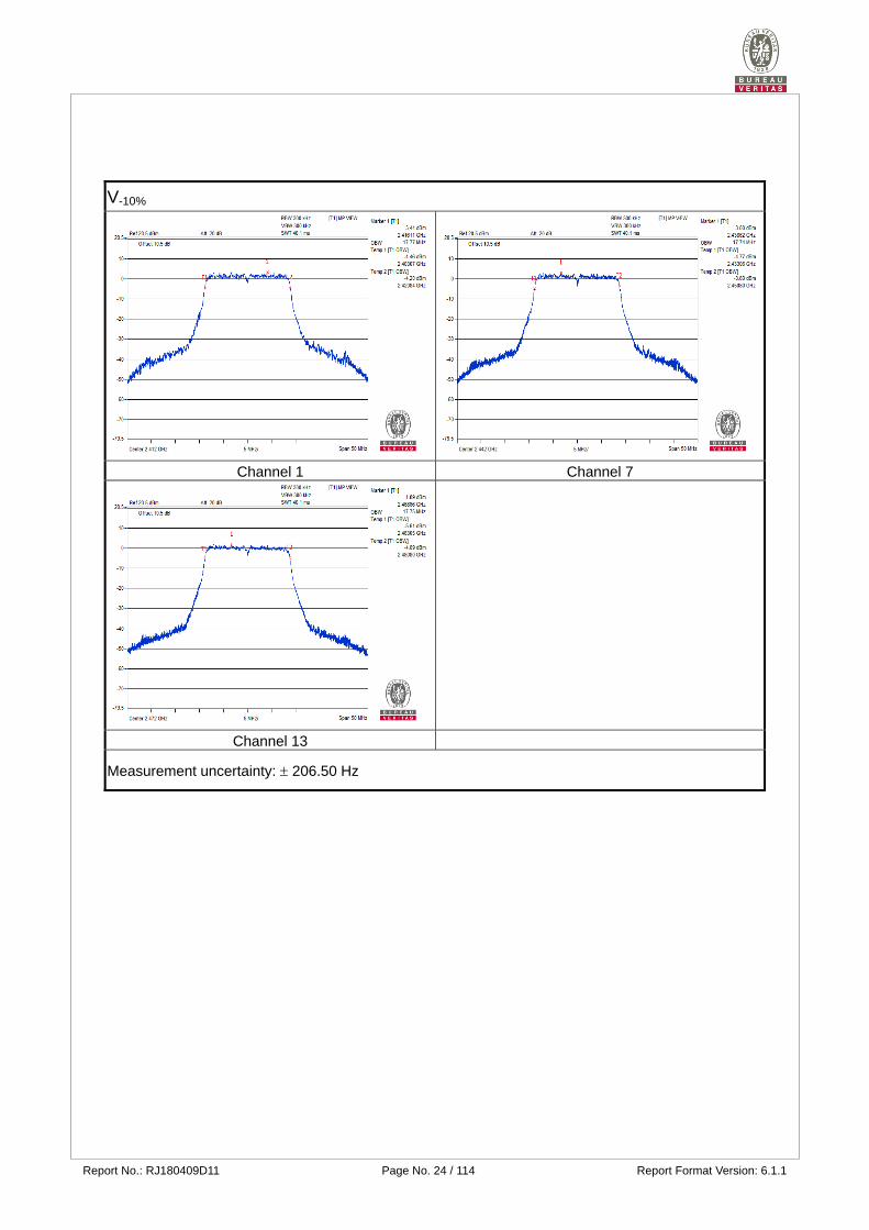
1 2412 17.75 17.73 17.77
7 2442 17.74 17.74 17.74
13 2472 17.75 17.75 17.75
Note: For the test plots please refer to the below pages.
Vnormal
Channel 1 Channel 7
Channel 13
Measurement uncertainty: 206.50 Hz
Report No.: RJ180409D11 Page No. 23 / 114 Report Format Version: 6.1.1
V+10%
Channel 1 Channel 7
Channel 13
Measurement uncertainty: 206.50 Hz
Report No.: RJ180409D11 Page No. 24 / 114 Report Format Version: 6.1.1
V-10%
Channel 1 Channel 7
Channel 13
Measurement uncertainty: 206.50 Hz
Report No.: RJ180409D11 Page No. 25 / 114 Report Format Version: 6.1.1
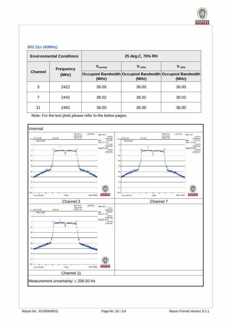
802.11n (40MHz)
Environmental Conditions 25 deg.C, 76% RH
Channel Frequency
(MHz)
Vnormal V+10% V-10%
Occupied Bandwidth (MHz)
Occupied Bandwidth (MHz)
Occupied Bandwidth (MHz)
3 2422 36.00 36.00 36.00
7 2442 36.02 36.02 36.02
11 2462 36.00 36.00 36.00
Note: For the test plots please refer to the below pages.
Vnormal
Channel 3 Channel 7
Channel 11
Measurement uncertainty: 206.50 Hz

Report No.: RJ180409D11 Page No. 26 / 114 Report Format Version: 6.1.1
V+10%
Channel 3 Channel 7
Channel 11
Measurement uncertainty: 206.50 Hz

Report No.: RJ180409D11 Page No. 27 / 114 Report Format Version: 6.1.1
V-10%
Channel 3 Channel 7
Channel 11
Measurement uncertainty: 206.50 Hz
Report No.: RJ180409D11 Page No. 28 / 114 Report Format Version: 6.1.1
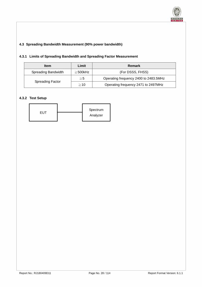
4.3 Spreading Bandwidth Measurement (90% power bandwidth)
4.3.1 Limits of Spreading Bandwidth and Spreading Factor Measurement
Item Limit Remark
Spreading Bandwidth ≧500kHz (For DSSS, FHSS)
Spreading Factor ≧5 Operating frequency 2400 to 2483.5MHz
≧10 Operating frequency 2471 to 2497MHz
4.3.2 Test Setup
EUT Spectrum
Analyzer
Report No.: RJ180409D11 Page No. 29 / 114 Report Format Version: 6.1.1
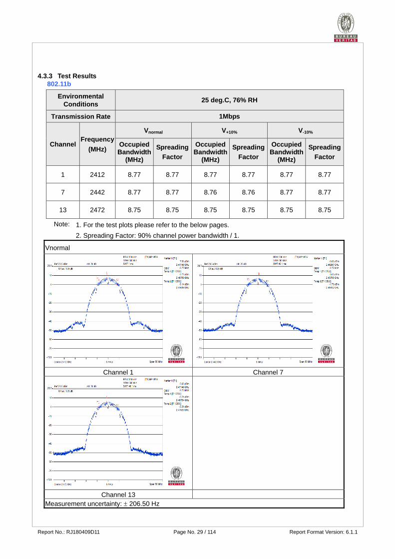
4.3.3 Test Results 802.11b
Environmental Conditions
25 deg.C, 76% RH
Transmission Rate 1Mbps
Channel Frequency
(MHz)
Vnormal V+10% V-10%
Occupied Bandwidth
(MHz)
Spreading
Factor
Occupied Bandwidth
(MHz)
Spreading
Factor
Occupied Bandwidth
(MHz)
Spreading
Factor
1 2412 8.77 8.77 8.77 8.77 8.77 8.77
7 2442 8.77 8.77 8.76 8.76 8.77 8.77
13 2472 8.75 8.75 8.75 8.75 8.75 8.75
Note: 1. For the test plots please refer to the below pages.
2. Spreading Factor: 90% channel power bandwidth / 1.
Vnormal
Channel 1 Channel 7
Channel 13 Measurement uncertainty: 206.50 Hz
Report No.: RJ180409D11 Page No. 30 / 114 Report Format Version: 6.1.1
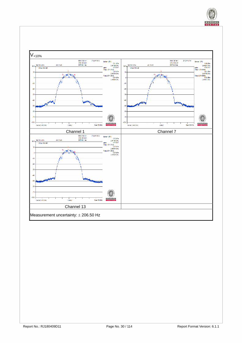
V+10%
Channel 1 Channel 7
Channel 13
Measurement uncertainty: 206.50 Hz
Report No.: RJ180409D11 Page No. 31 / 114 Report Format Version: 6.1.1
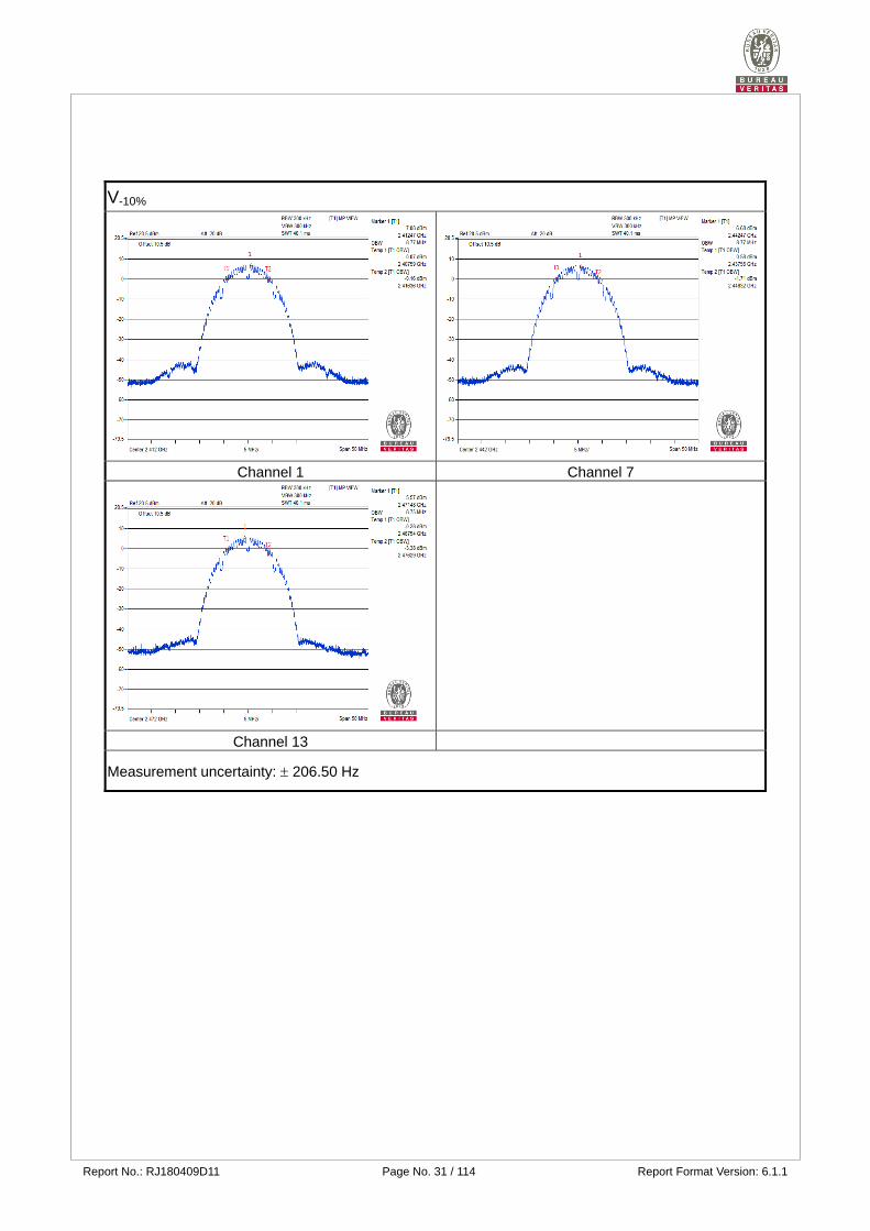
V-10%
Channel 1 Channel 7
Channel 13
Measurement uncertainty: 206.50 Hz
Report No.: RJ180409D11 Page No. 32 / 114 Report Format Version: 6.1.1
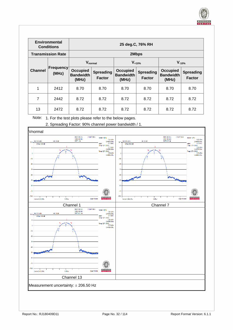
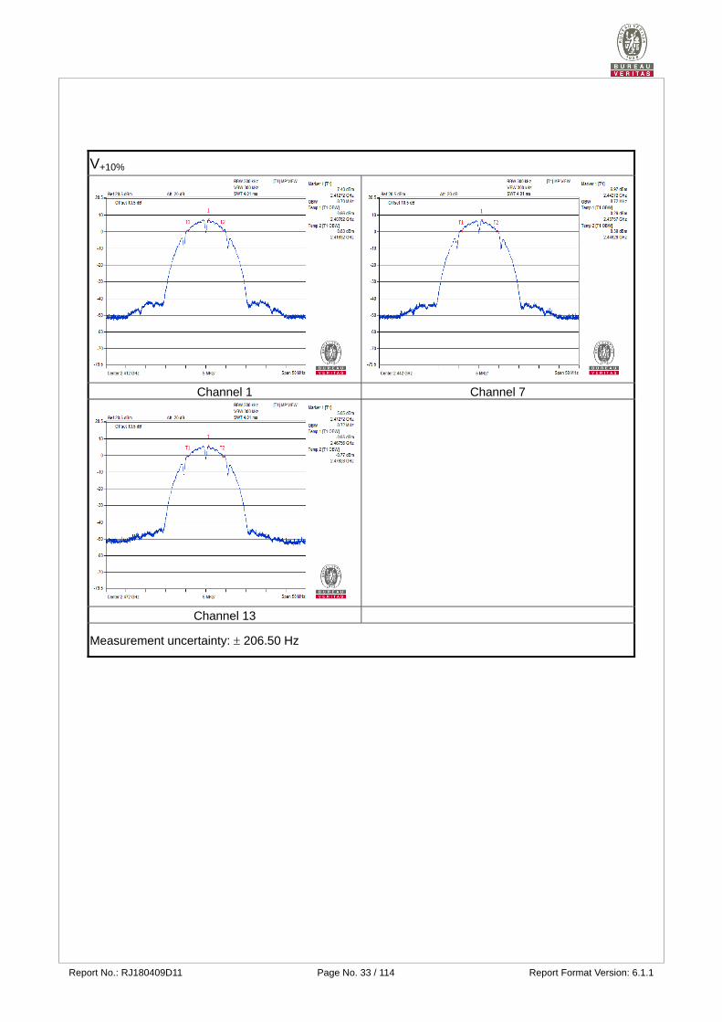
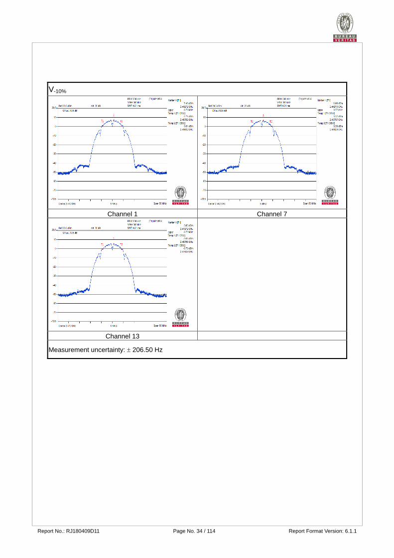
Environmental Conditions
25 deg.C, 76% RH
Transmission Rate 2Mbps
Channel Frequency
(MHz)
Vnormal V+10% V-10%
Occupied Bandwidth
(MHz)
Spreading
Factor
Occupied Bandwidth
(MHz)
Spreading
Factor
Occupied Bandwidth
(MHz)
Spreading
Factor
1 2412 8.70 8.70 8.70 8.70 8.70 8.70
7 2442 8.72 8.72 8.72 8.72 8.72 8.72
13 2472 8.72 8.72 8.72 8.72 8.72 8.72
Note: 1. For the test plots please refer to the below pages.
2. Spreading Factor: 90% channel power bandwidth / 1.
Vnormal
Channel 1 Channel 7
Channel 13
Measurement uncertainty: 206.50 Hz
Report No.: RJ180409D11 Page No. 33 / 114 Report Format Version: 6.1.1
V+10%
Channel 1 Channel 7
Channel 13
Measurement uncertainty: 206.50 Hz
Report No.: RJ180409D11 Page No. 34 / 114 Report Format Version: 6.1.1
V-10%
Channel 1 Channel 7
Channel 13
Measurement uncertainty: 206.50 Hz
Report No.: RJ180409D11 Page No. 35 / 114 Report Format Version: 6.1.1
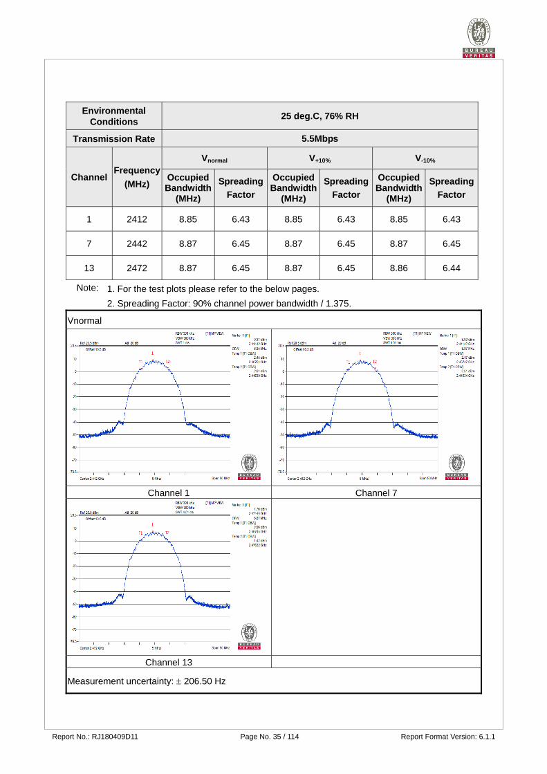
Environmental Conditions
25 deg.C, 76% RH
Transmission Rate 5.5Mbps
Channel Frequency
(MHz)
Vnormal V+10% V-10%
Occupied Bandwidth
(MHz)
Spreading
Factor
Occupied Bandwidth
(MHz)
Spreading
Factor
Occupied Bandwidth
(MHz)
Spreading
Factor
1 2412 8.85 6.43 8.85 6.43 8.85 6.43
7 2442 8.87 6.45 8.87 6.45 8.87 6.45
13 2472 8.87 6.45 8.87 6.45 8.86 6.44
Note: 1. For the test plots please refer to the below pages.
2. Spreading Factor: 90% channel power bandwidth / 1.375.
Vnormal
Channel 1 Channel 7
Channel 13
Measurement uncertainty: 206.50 Hz

Report No.: RJ180409D11 Page No. 36 / 114 Report Format Version: 6.1.1
V+10%
Channel 1 Channel 7
Channel 13
Measurement uncertainty: 206.50 Hz

Report No.: RJ180409D11 Page No. 37 / 114 Report Format Version: 6.1.1
V-10%
Channel 1 Channel 7
Channel 13
Measurement uncertainty: 206.50 Hz
Report No.: RJ180409D11 Page No. 38 / 114 Report Format Version: 6.1.1
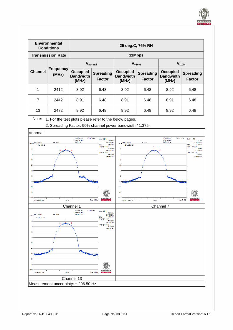
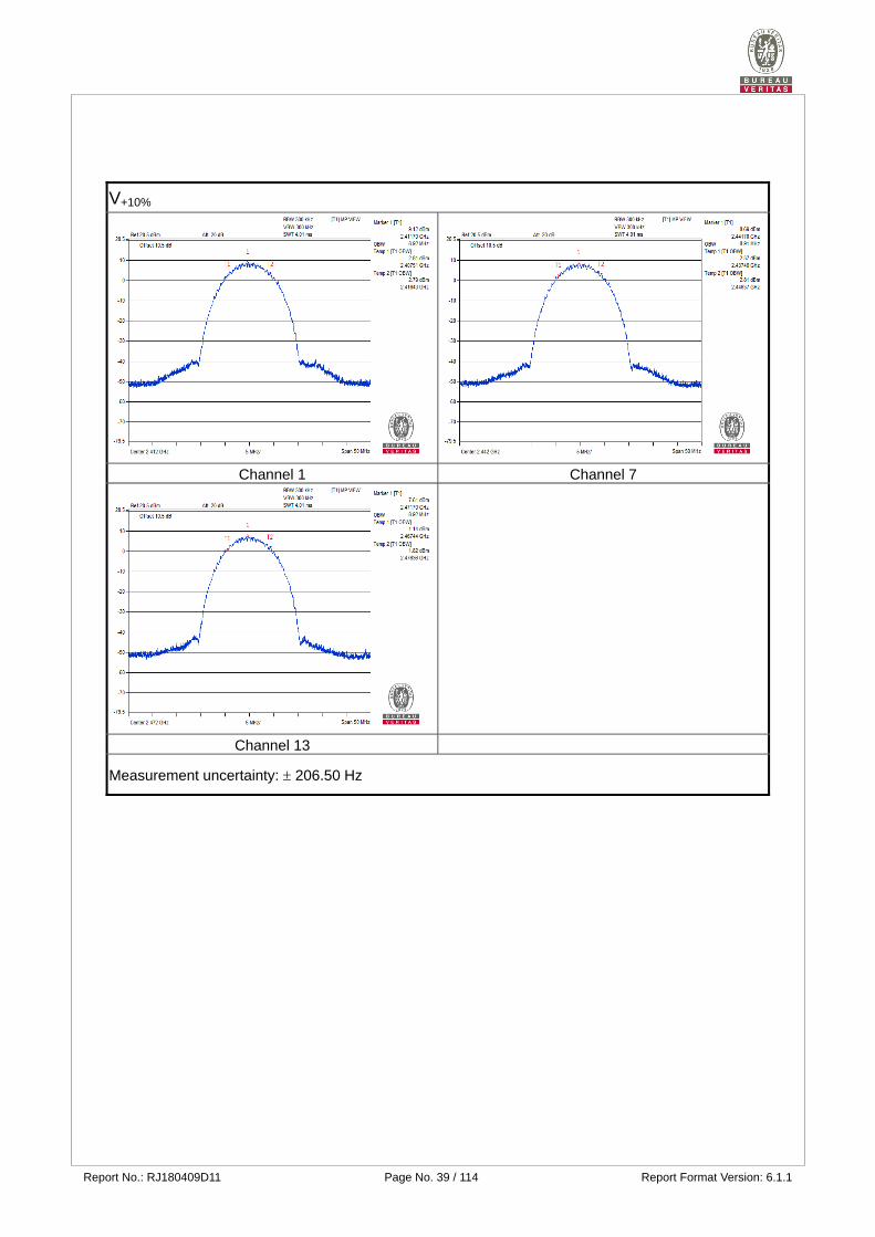
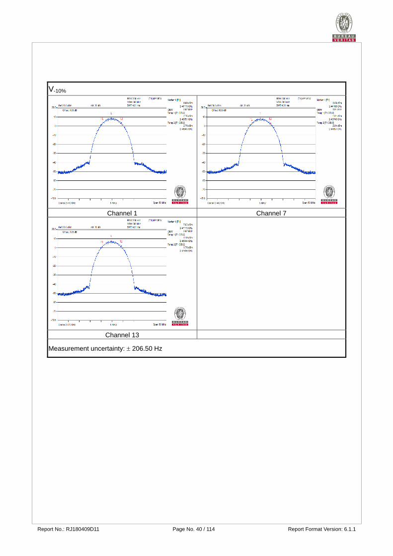
Environmental Conditions
25 deg.C, 76% RH
Transmission Rate 11Mbps
Channel Frequency
(MHz)
Vnormal V+10% V-10%
Occupied Bandwidth
(MHz)
Spreading
Factor
Occupied Bandwidth
(MHz)
Spreading
Factor
Occupied Bandwidth
(MHz)
Spreading
Factor
1 2412 8.92 6.48 8.92 6.48 8.92 6.48
7 2442 8.91 6.48 8.91 6.48 8.91 6.48
13 2472 8.92 6.48 8.92 6.48 8.92 6.48
Note: 1. For the test plots please refer to the below pages.
2. Spreading Factor: 90% channel power bandwidth / 1.375.
Vnormal
Channel 1 Channel 7
Channel 13 Measurement uncertainty: 206.50 Hz
Report No.: RJ180409D11 Page No. 39 / 114 Report Format Version: 6.1.1
V+10%
Channel 1 Channel 7
Channel 13
Measurement uncertainty: 206.50 Hz
Report No.: RJ180409D11 Page No. 40 / 114 Report Format Version: 6.1.1
V-10%
Channel 1 Channel 7
Channel 13
Measurement uncertainty: 206.50 Hz
Report No.: RJ180409D11 Page No. 41 / 114 Report Format Version: 6.1.1
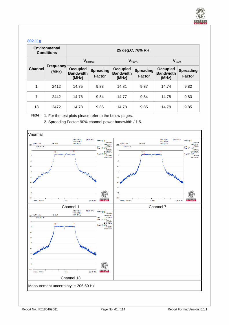
802.11g
Environmental Conditions
25 deg.C, 76% RH
Channel Frequency
(MHz)
Vnormal V+10% V-10%
Occupied Bandwidth
(MHz)
Spreading
Factor
Occupied Bandwidth
(MHz)
Spreading
Factor
Occupied Bandwidth
(MHz)
Spreading
Factor
1 2412 14.75 9.83 14.81 9.87 14.74 9.82
7 2442 14.76 9.84 14.77 9.84 14.75 9.83
13 2472 14.78 9.85 14.78 9.85 14.78 9.85
Note: 1. For the test plots please refer to the below pages.
2. Spreading Factor: 90% channel power bandwidth / 1.5.
Vnormal
Channel 1 Channel 7
Channel 13
Measurement uncertainty: 206.50 Hz
Report No.: RJ180409D11 Page No. 42 / 114 Report Format Version: 6.1.1
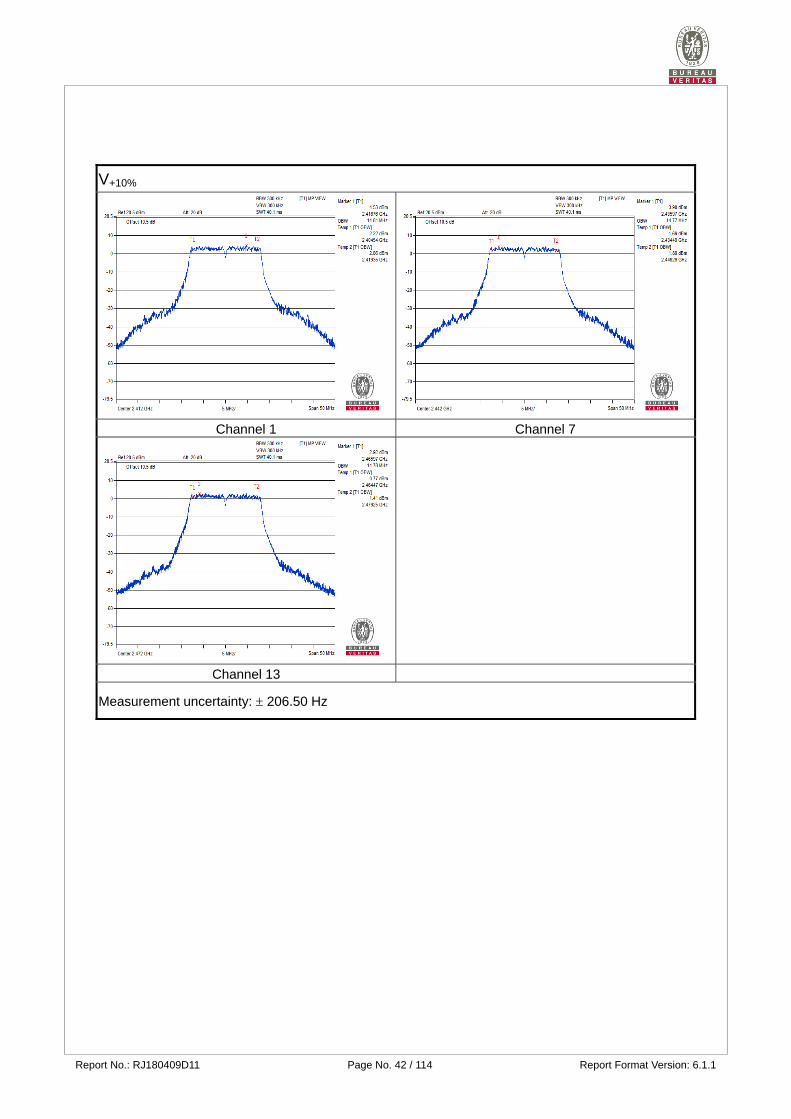
V+10%
Channel 1 Channel 7
Channel 13
Measurement uncertainty: 206.50 Hz

Report No.: RJ180409D11 Page No. 43 / 114 Report Format Version: 6.1.1
V-10%
Channel 1 Channel 7
Channel 13
Measurement uncertainty: 206.50 Hz
Report No.: RJ180409D11 Page No. 44 / 114 Report Format Version: 6.1.1
802.11n (20MHz)
Environmental Conditions
25 deg.C, 76% RH
Channel Frequency
(MHz)
Vnormal V+10% V-10%
Occupied Bandwidth
(MHz)
Spreading
Factor
Occupied Bandwidth
(MHz)
Spreading
Factor
Occupied Bandwidth
(MHz)
Spreading
Factor
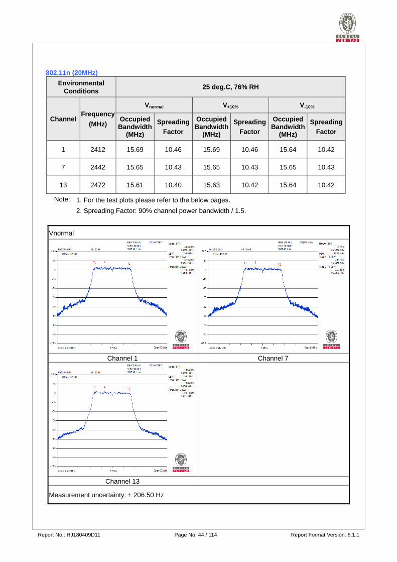
1 2412 15.69 10.46 15.69 10.46 15.64 10.42
7 2442 15.65 10.43 15.65 10.43 15.65 10.43
13 2472 15.61 10.40 15.63 10.42 15.64 10.42
Note: 1. For the test plots please refer to the below pages.
2. Spreading Factor: 90% channel power bandwidth / 1.5.
Vnormal
Channel 1 Channel 7
Channel 13
Measurement uncertainty: 206.50 Hz
Report No.: RJ180409D11 Page No. 45 / 114 Report Format Version: 6.1.1
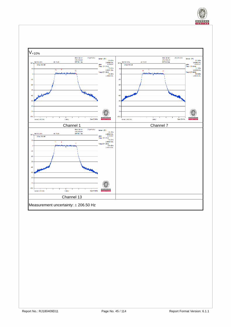
V+10%
Channel 1 Channel 7
Channel 13
Measurement uncertainty: 206.50 Hz
Report No.: RJ180409D11 Page No. 46 / 114 Report Format Version: 6.1.1
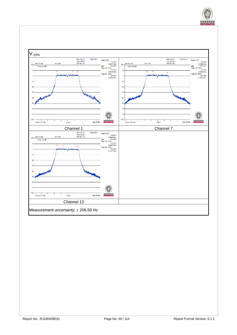
V-10%
Channel 1 Channel 7
Channel 13
Measurement uncertainty: 206.50 Hz
Report No.: RJ180409D11 Page No. 47 / 114 Report Format Version: 6.1.1
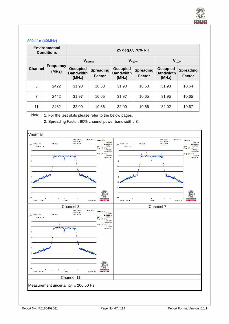
802.11n (40MHz)
Environmental Conditions
25 deg.C, 76% RH
Channel Frequency
(MHz)
Vnormal V+10% V-10%
Occupied Bandwidth
(MHz)
Spreading
Factor
Occupied Bandwidth
(MHz)
Spreading
Factor
Occupied Bandwidth
(MHz)
Spreading
Factor
3 2422 31.90 10.63 31.90 10.63 31.93 10.64
7 2442 31.97 10.65 31.97 10.65 31.95 10.65
11 2462 32.00 10.66 32.00 10.66 32.02 10.67
Note: 1. For the test plots please refer to the below pages.
2. Spreading Factor: 90% channel power bandwidth / 3.
Vnormal
Channel 3 Channel 7
Channel 11
Measurement uncertainty: 206.50 Hz
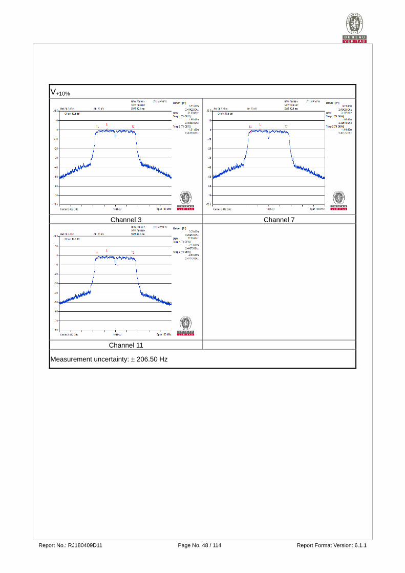
Report No.: RJ180409D11 Page No. 48 / 114 Report Format Version: 6.1.1
V+10%
Channel 3 Channel 7
Channel 11
Measurement uncertainty: 206.50 Hz
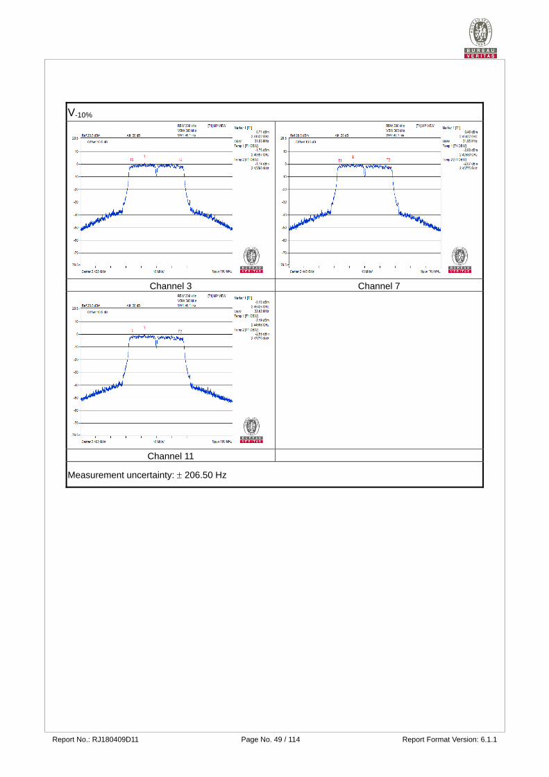
Report No.: RJ180409D11 Page No. 49 / 114 Report Format Version: 6.1.1
V-10%
Channel 3 Channel 7
Channel 11
Measurement uncertainty: 206.50 Hz
Report No.: RJ180409D11 Page No. 50 / 114 Report Format Version: 6.1.1
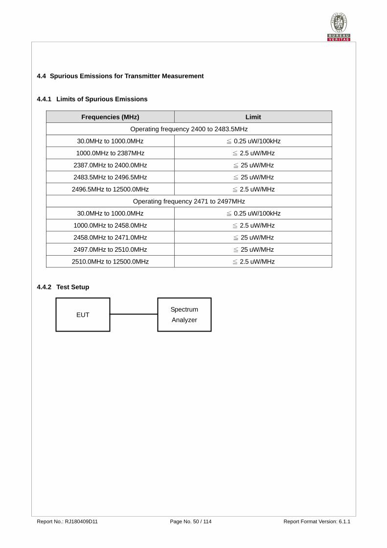
4.4 Spurious Emissions for Transmitter Measurement
4.4.1 Limits of Spurious Emissions
Frequencies (MHz) Limit
Operating frequency 2400 to 2483.5MHz
30.0MHz to 1000.0MHz ≦ 0.25 uW/100kHz
1000.0MHz to 2387MHz ≦ 2.5 uW/MHz
2387.0MHz to 2400.0MHz ≦ 25 uW/MHz
2483.5MHz to 2496.5MHz ≦ 25 uW/MHz
2496.5MHz to 12500.0MHz ≦ 2.5 uW/MHz
Operating frequency 2471 to 2497MHz
30.0MHz to 1000.0MHz ≦ 0.25 uW/100kHz
1000.0MHz to 2458.0MHz ≦ 2.5 uW/MHz
2458.0MHz to 2471.0MHz ≦ 25 uW/MHz
2497.0MHz to 2510.0MHz ≦ 25 uW/MHz
2510.0MHz to 12500.0MHz ≦ 2.5 uW/MHz
4.4.2 Test Setup
EUT Spectrum
Analyzer
Report No.: RJ180409D11 Page No. 51 / 114 Report Format Version: 6.1.1
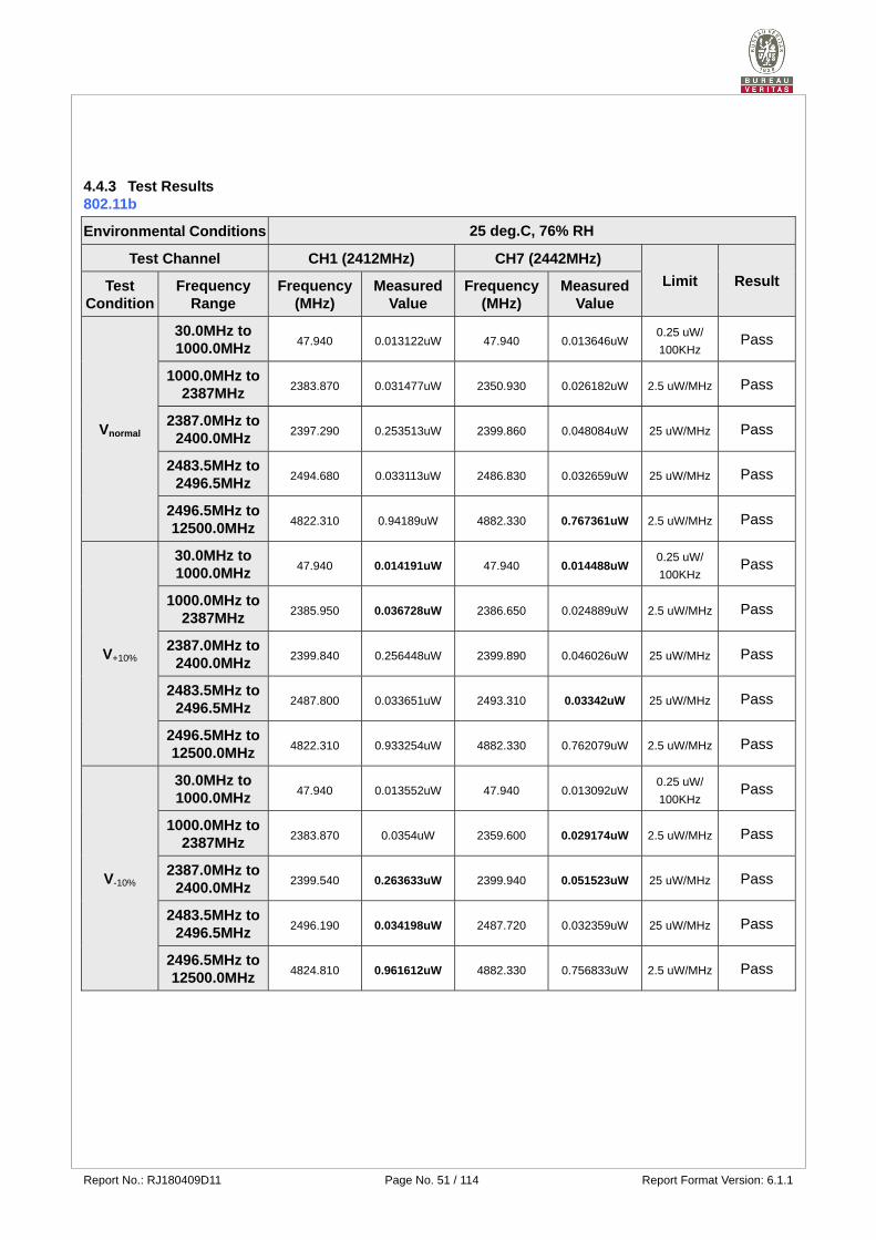
4.4.3 Test Results 802.11b
Environmental Conditions 25 deg.C, 76% RH
Test Channel CH1 (2412MHz) CH7 (2442MHz)
Limit Result Test Condition
Frequency Range
Frequency (MHz)
Measured Value
Frequency (MHz)
Measured Value
Vnormal
30.0MHz to 1000.0MHz
47.940 0.013122uW 47.940 0.013646uW 0.25 uW/
100KHz Pass
1000.0MHz to 2387MHz
2383.870 0.031477uW 2350.930 0.026182uW 2.5 uW/MHz Pass
2387.0MHz to 2400.0MHz
2397.290 0.253513uW 2399.860 0.048084uW 25 uW/MHz Pass
2483.5MHz to 2496.5MHz
2494.680 0.033113uW 2486.830 0.032659uW 25 uW/MHz Pass
2496.5MHz to 12500.0MHz
4822.310 0.94189uW 4882.330 0.767361uW 2.5 uW/MHz Pass
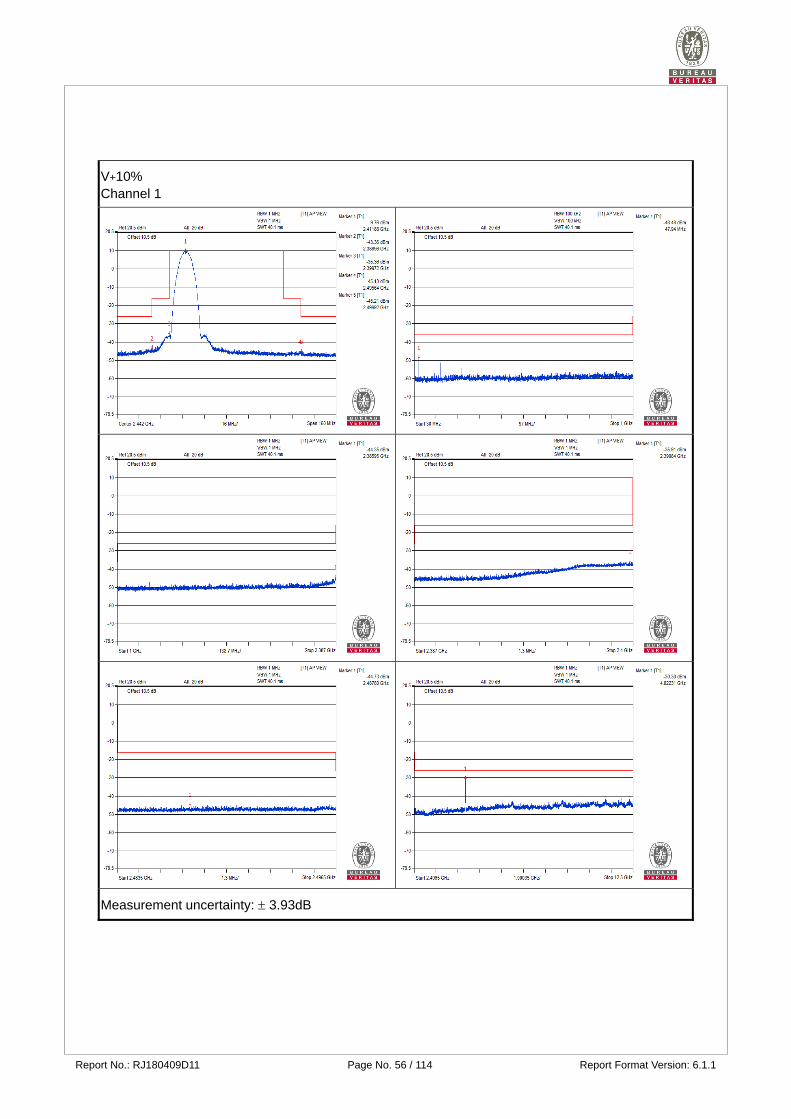
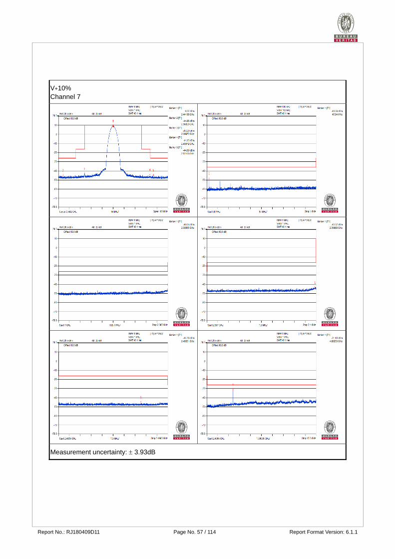
V+10%
30.0MHz to 1000.0MHz
47.940 0.014191uW 47.940 0.014488uW 0.25 uW/
100KHz Pass
1000.0MHz to 2387MHz
2385.950 0.036728uW 2386.650 0.024889uW 2.5 uW/MHz Pass
2387.0MHz to 2400.0MHz
2399.840 0.256448uW 2399.890 0.046026uW 25 uW/MHz Pass
2483.5MHz to 2496.5MHz
2487.800 0.033651uW 2493.310 0.03342uW 25 uW/MHz Pass
2496.5MHz to 12500.0MHz
4822.310 0.933254uW 4882.330 0.762079uW 2.5 uW/MHz Pass
V-10%
30.0MHz to 1000.0MHz
47.940 0.013552uW 47.940 0.013092uW 0.25 uW/
100KHz Pass
1000.0MHz to 2387MHz
2383.870 0.0354uW 2359.600 0.029174uW 2.5 uW/MHz Pass
2387.0MHz to 2400.0MHz
2399.540 0.263633uW 2399.940 0.051523uW 25 uW/MHz Pass
2483.5MHz to 2496.5MHz
2496.190 0.034198uW 2487.720 0.032359uW 25 uW/MHz Pass
2496.5MHz to 12500.0MHz
4824.810 0.961612uW 4882.330 0.756833uW 2.5 uW/MHz Pass
Report No.: RJ180409D11 Page No. 52 / 114 Report Format Version: 6.1.1
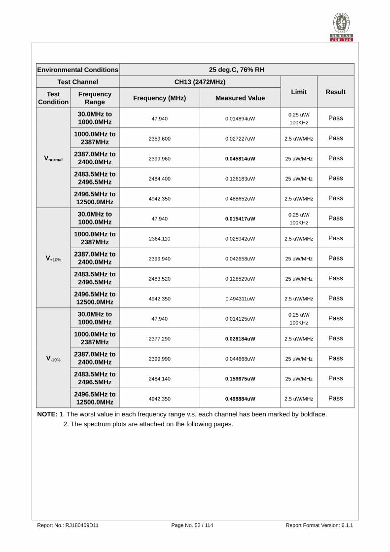
Environmental Conditions 25 deg.C, 76% RH
Test Channel CH13 (2472MHz)
Limit Result Test Condition
Frequency Range
Frequency (MHz) Measured Value
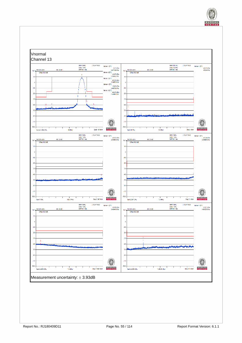
Vnormal
30.0MHz to 1000.0MHz
47.940 0.014894uW 0.25 uW/
100KHz Pass
1000.0MHz to 2387MHz
2359.600 0.027227uW 2.5 uW/MHz Pass
2387.0MHz to 2400.0MHz
2399.960 0.045814uW 25 uW/MHz Pass
2483.5MHz to 2496.5MHz
2484.400 0.126183uW 25 uW/MHz Pass
2496.5MHz to 12500.0MHz
4942.350 0.488652uW 2.5 uW/MHz Pass
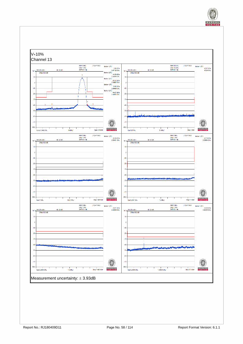
V+10%
30.0MHz to 1000.0MHz
47.940 0.015417uW 0.25 uW/
100KHz Pass
1000.0MHz to 2387MHz
2364.110 0.025942uW 2.5 uW/MHz Pass
2387.0MHz to 2400.0MHz
2399.940 0.042658uW 25 uW/MHz Pass
2483.5MHz to 2496.5MHz
2483.520 0.128529uW 25 uW/MHz Pass
2496.5MHz to 12500.0MHz
4942.350 0.494311uW 2.5 uW/MHz Pass
V-10%
30.0MHz to 1000.0MHz
47.940 0.014125uW 0.25 uW/
100KHz Pass
1000.0MHz to 2387MHz
2377.290 0.028184uW 2.5 uW/MHz Pass
2387.0MHz to 2400.0MHz
2399.990 0.044668uW 25 uW/MHz Pass
2483.5MHz to 2496.5MHz
2484.140 0.156675uW 25 uW/MHz Pass
2496.5MHz to 12500.0MHz
4942.350 0.498884uW 2.5 uW/MHz Pass
NOTE: 1. The worst value in each frequency range v.s. each channel has been marked by boldface.
2. The spectrum plots are attached on the following pages.
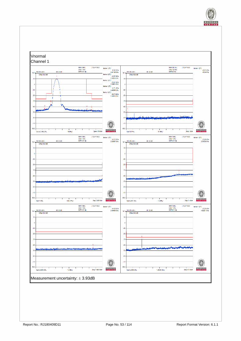
Report No.: RJ180409D11 Page No. 53 / 114 Report Format Version: 6.1.1
Vnormal Channel 1
Measurement uncertainty: 3.93dB
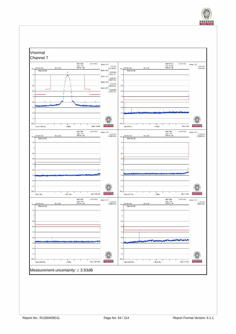
Report No.: RJ180409D11 Page No. 54 / 114 Report Format Version: 6.1.1
Vnormal Channel 7
Measurement uncertainty: 3.93dB
Report No.: RJ180409D11 Page No. 55 / 114 Report Format Version: 6.1.1
Vnormal Channel 13
Measurement uncertainty: 3.93dB
Report No.: RJ180409D11 Page No. 56 / 114 Report Format Version: 6.1.1
V+10% Channel 1
Measurement uncertainty: 3.93dB
Report No.: RJ180409D11 Page No. 57 / 114 Report Format Version: 6.1.1
V+10% Channel 7
Measurement uncertainty: 3.93dB
Report No.: RJ180409D11 Page No. 58 / 114 Report Format Version: 6.1.1
V+10% Channel 13
Measurement uncertainty: 3.93dB
Report No.: RJ180409D11 Page No. 59 / 114 Report Format Version: 6.1.1
V-10% Channel 1
Measurement uncertainty: 3.93dB
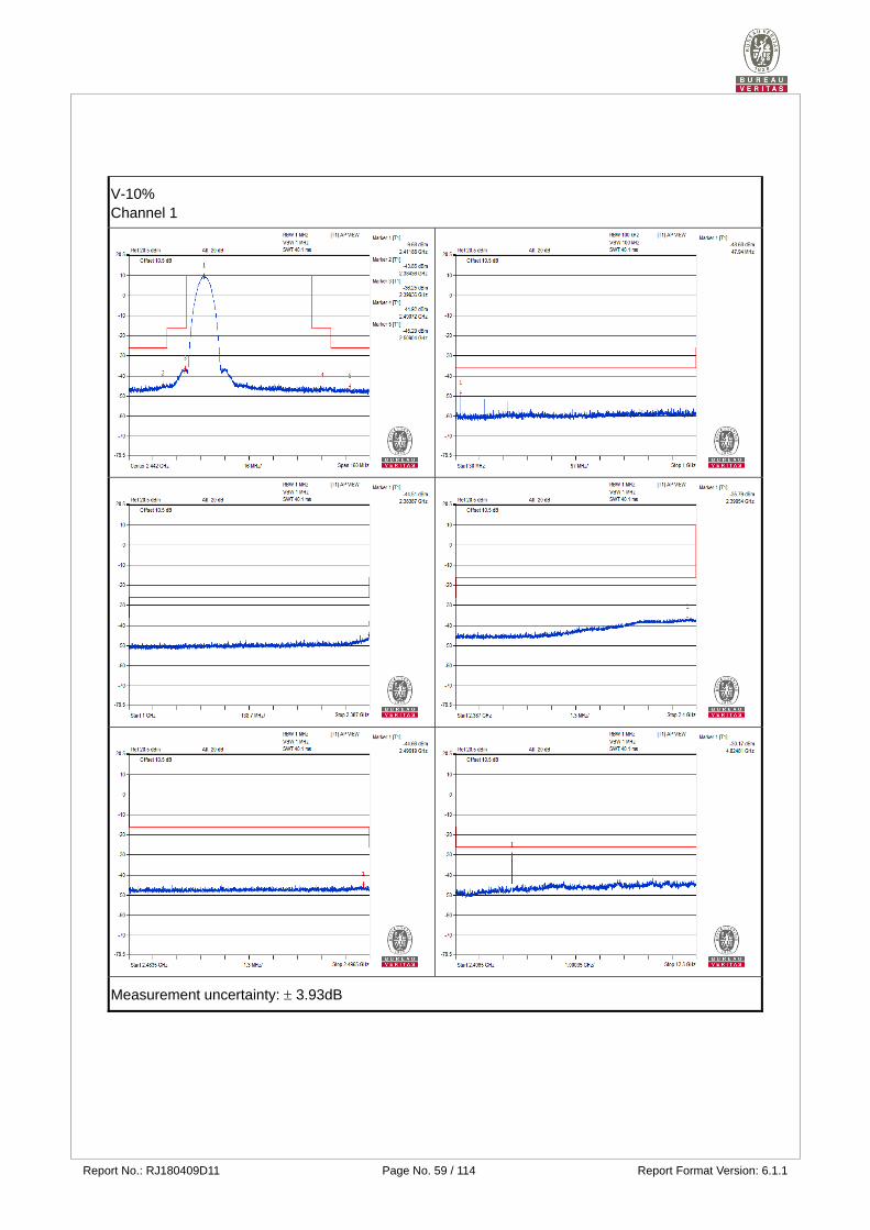
Report No.: RJ180409D11 Page No. 60 / 114 Report Format Version: 6.1.1
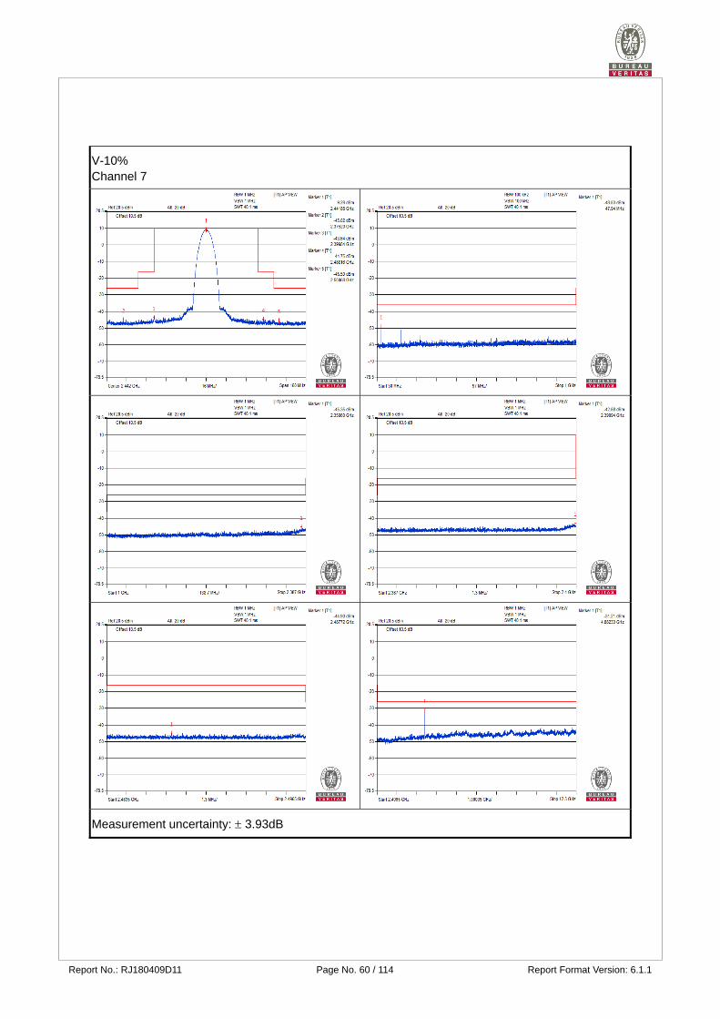
V-10% Channel 7
Measurement uncertainty: 3.93dB
Report No.: RJ180409D11 Page No. 61 / 114 Report Format Version: 6.1.1
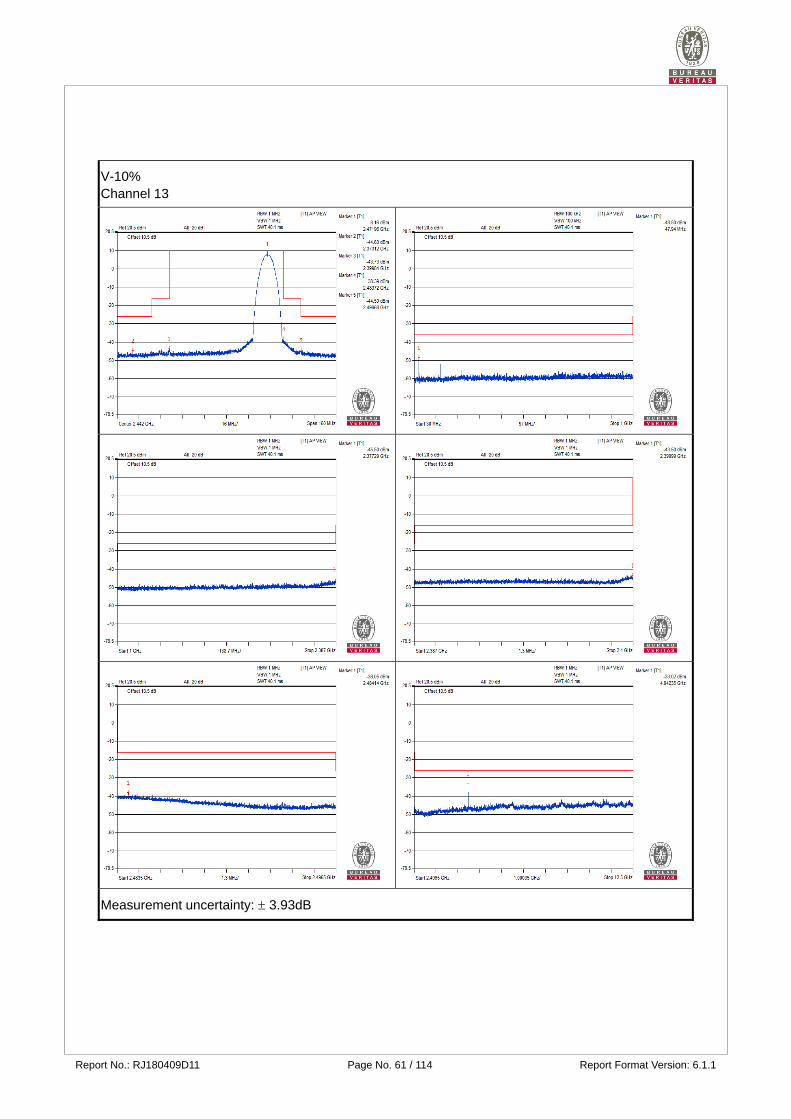
V-10% Channel 13
Measurement uncertainty: 3.93dB
Report No.: RJ180409D11 Page No. 62 / 114 Report Format Version: 6.1.1
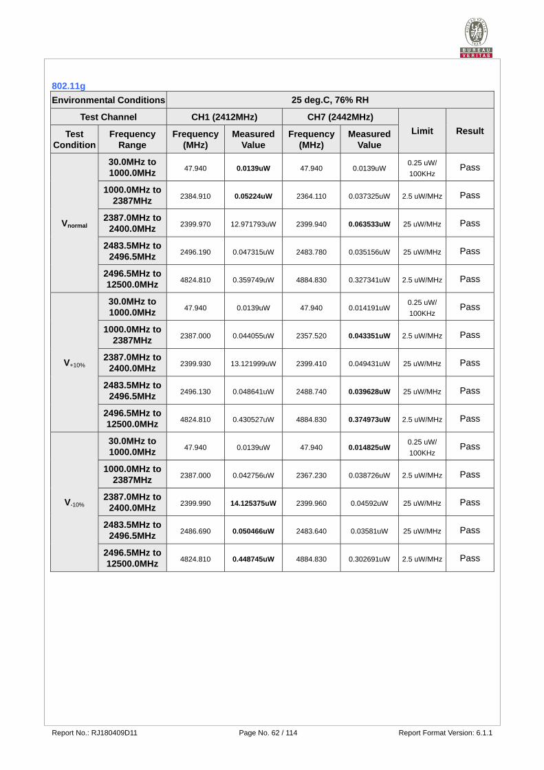
802.11g
Environmental Conditions 25 deg.C, 76% RH
Test Channel CH1 (2412MHz) CH7 (2442MHz)
Limit Result Test Condition
Frequency Range
Frequency (MHz)
Measured Value
Frequency (MHz)
Measured Value
Vnormal
30.0MHz to 1000.0MHz
47.940 0.0139uW 47.940 0.0139uW 0.25 uW/
100KHz Pass
1000.0MHz to 2387MHz
2384.910 0.05224uW 2364.110 0.037325uW 2.5 uW/MHz Pass
2387.0MHz to 2400.0MHz
2399.970 12.971793uW 2399.940 0.063533uW 25 uW/MHz Pass
2483.5MHz to 2496.5MHz
2496.190 0.047315uW 2483.780 0.035156uW 25 uW/MHz Pass
2496.5MHz to 12500.0MHz
4824.810 0.359749uW 4884.830 0.327341uW 2.5 uW/MHz Pass
V+10%
30.0MHz to 1000.0MHz
47.940 0.0139uW 47.940 0.014191uW 0.25 uW/
100KHz Pass
1000.0MHz to 2387MHz
2387.000 0.044055uW 2357.520 0.043351uW 2.5 uW/MHz Pass
2387.0MHz to 2400.0MHz
2399.930 13.121999uW 2399.410 0.049431uW 25 uW/MHz Pass
2483.5MHz to 2496.5MHz
2496.130 0.048641uW 2488.740 0.039628uW 25 uW/MHz Pass
2496.5MHz to 12500.0MHz
4824.810 0.430527uW 4884.830 0.374973uW 2.5 uW/MHz Pass
V-10%
30.0MHz to 1000.0MHz
47.940 0.0139uW 47.940 0.014825uW 0.25 uW/
100KHz Pass
1000.0MHz to 2387MHz
2387.000 0.042756uW 2367.230 0.038726uW 2.5 uW/MHz Pass
2387.0MHz to 2400.0MHz
2399.990 14.125375uW 2399.960 0.04592uW 25 uW/MHz Pass
2483.5MHz to 2496.5MHz
2486.690 0.050466uW 2483.640 0.03581uW 25 uW/MHz Pass
2496.5MHz to 12500.0MHz
4824.810 0.448745uW 4884.830 0.302691uW 2.5 uW/MHz Pass
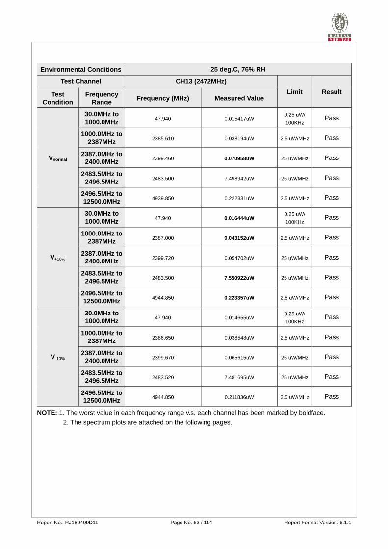
Report No.: RJ180409D11 Page No. 63 / 114 Report Format Version: 6.1.1
Environmental Conditions 25 deg.C, 76% RH
Test Channel CH13 (2472MHz)
Limit Result Test Condition
Frequency Range
Frequency (MHz) Measured Value
Vnormal
30.0MHz to 1000.0MHz
47.940 0.015417uW 0.25 uW/
100KHz Pass
1000.0MHz to 2387MHz
2385.610 0.038194uW 2.5 uW/MHz Pass
2387.0MHz to 2400.0MHz
2399.460 0.070958uW 25 uW/MHz Pass
2483.5MHz to 2496.5MHz
2483.500 7.498942uW 25 uW/MHz Pass
2496.5MHz to 12500.0MHz
4939.850 0.222331uW 2.5 uW/MHz Pass
V+10%
30.0MHz to 1000.0MHz
47.940 0.016444uW 0.25 uW/
100KHz Pass
1000.0MHz to 2387MHz
2387.000 0.043152uW 2.5 uW/MHz Pass
2387.0MHz to 2400.0MHz
2399.720 0.054702uW 25 uW/MHz Pass
2483.5MHz to 2496.5MHz
2483.500 7.550922uW 25 uW/MHz Pass
2496.5MHz to 12500.0MHz
4944.850 0.223357uW 2.5 uW/MHz Pass
V-10%
30.0MHz to 1000.0MHz
47.940 0.014655uW 0.25 uW/
100KHz Pass
1000.0MHz to 2387MHz
2386.650 0.038548uW 2.5 uW/MHz Pass
2387.0MHz to 2400.0MHz
2399.670 0.065615uW 25 uW/MHz Pass
2483.5MHz to 2496.5MHz
2483.520 7.481695uW 25 uW/MHz Pass
2496.5MHz to 12500.0MHz
4944.850 0.211836uW 2.5 uW/MHz Pass
NOTE: 1. The worst value in each frequency range v.s. each channel has been marked by boldface.
2. The spectrum plots are attached on the following pages.
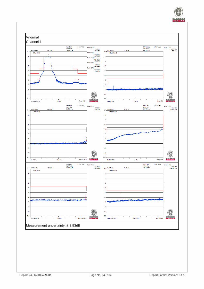
Report No.: RJ180409D11 Page No. 64 / 114 Report Format Version: 6.1.1
Vnormal Channel 1
Measurement uncertainty: 3.93dB
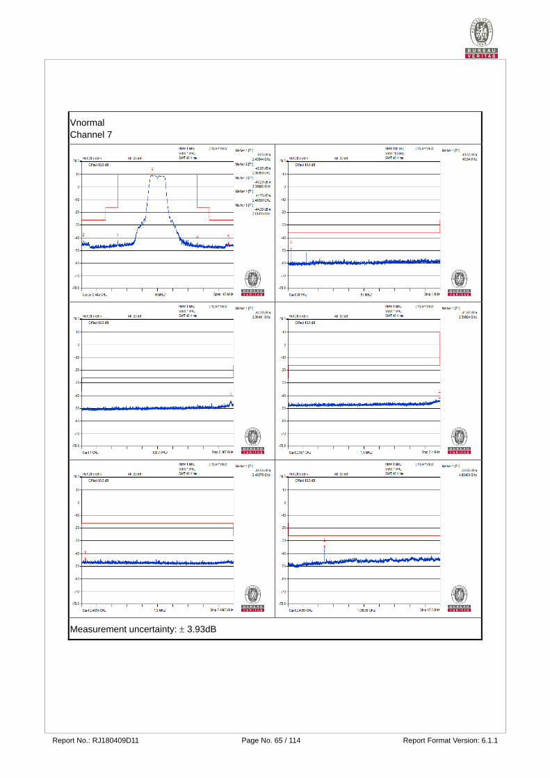
Report No.: RJ180409D11 Page No. 65 / 114 Report Format Version: 6.1.1
Vnormal Channel 7
Measurement uncertainty: 3.93dB

Report No.: RJ180409D11 Page No. 66 / 114 Report Format Version: 6.1.1
Vnormal Channel 13
Measurement uncertainty: 3.93dB
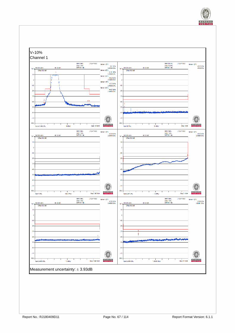
Report No.: RJ180409D11 Page No. 67 / 114 Report Format Version: 6.1.1
V+10% Channel 1
Measurement uncertainty: 3.93dB
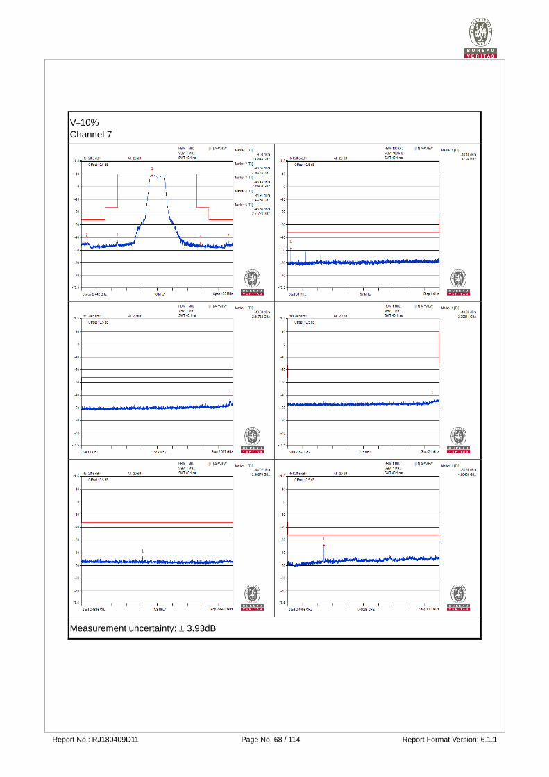
Report No.: RJ180409D11 Page No. 68 / 114 Report Format Version: 6.1.1
V+10% Channel 7
Measurement uncertainty: 3.93dB
Report No.: RJ180409D11 Page No. 69 / 114 Report Format Version: 6.1.1
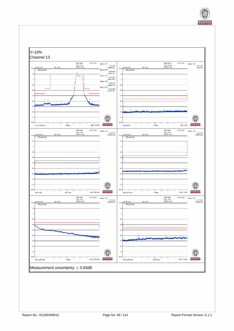
V+10% Channel 13
Measurement uncertainty: 3.93dB

Report No.: RJ180409D11 Page No. 70 / 114 Report Format Version: 6.1.1
V-10% Channel 1
Measurement uncertainty: 3.93dB
Report No.: RJ180409D11 Page No. 71 / 114 Report Format Version: 6.1.1
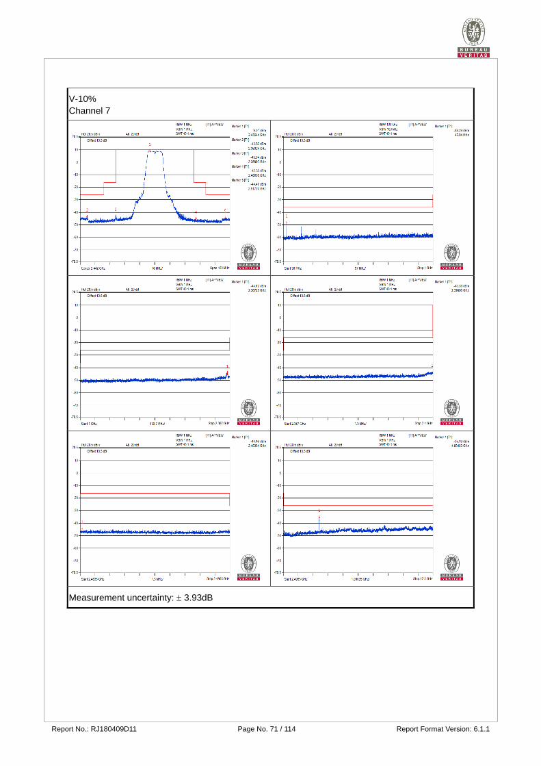
V-10% Channel 7
Measurement uncertainty: 3.93dB
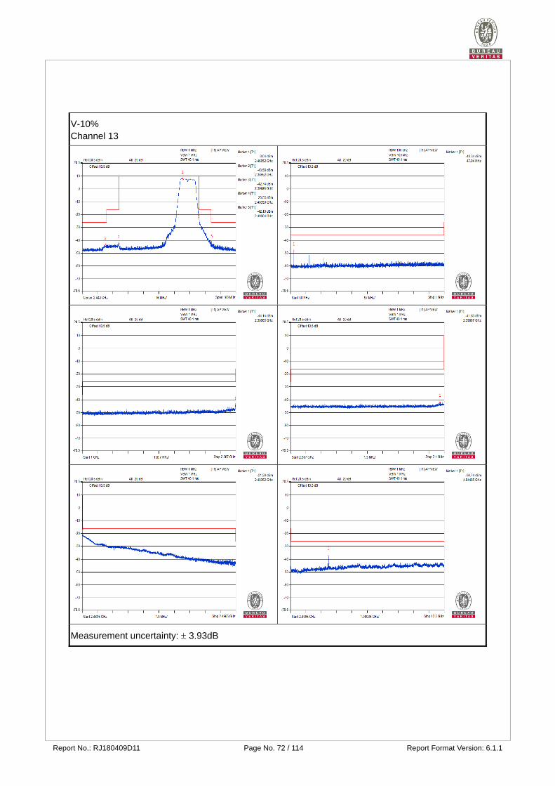
Report No.: RJ180409D11 Page No. 72 / 114 Report Format Version: 6.1.1
V-10% Channel 13
Measurement uncertainty: 3.93dB
Report No.: RJ180409D11 Page No. 73 / 114 Report Format Version: 6.1.1
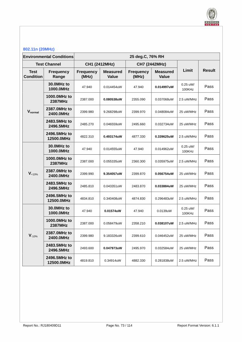
802.11n (20MHz)
Environmental Conditions 25 deg.C, 76% RH
Test Channel CH1 (2412MHz) CH7 (2442MHz)
Limit Result Test Condition
Frequency Range
Frequency (MHz)
Measured Value
Frequency (MHz)
Measured Value
Vnormal
30.0MHz to 1000.0MHz
47.940 0.014454uW 47.940 0.014997uW 0.25 uW/
100KHz Pass
1000.0MHz to 2387MHz
2387.000 0.080538uW 2355.090 0.037068uW 2.5 uW/MHz Pass
2387.0MHz to 2400.0MHz
2399.980 9.268298uW 2399.970 0.048084uW 25 uW/MHz Pass
2483.5MHz to 2496.5MHz
2485.270 0.046559uW 2495.660 0.032734uW 25 uW/MHz Pass
2496.5MHz to 12500.0MHz
4822.310 0.493174uW 4877.330 0.339625uW 2.5 uW/MHz Pass
V+10%
30.0MHz to 1000.0MHz
47.940 0.014555uW 47.940 0.014962uW 0.25 uW/
100KHz Pass
1000.0MHz to 2387MHz
2387.000 0.055335uW 2360.300 0.035975uW 2.5 uW/MHz Pass
2387.0MHz to 2400.0MHz
2399.990 9.354057uW 2399.870 0.056754uW 25 uW/MHz Pass
2483.5MHz to 2496.5MHz
2485.810 0.043351uW 2483.870 0.033884uW 25 uW/MHz Pass
2496.5MHz to 12500.0MHz
4834.810 0.340408uW 4874.830 0.296483uW 2.5 uW/MHz Pass
V-10%
30.0MHz to 1000.0MHz
47.940 0.01574uW 47.940 0.0139uW 0.25 uW/
100KHz Pass
1000.0MHz to 2387MHz
2387.000 0.058479uW 2358.210 0.038107uW 2.5 uW/MHz Pass
2387.0MHz to 2400.0MHz
2399.980 9.183326uW 2399.610 0.046452uW 25 uW/MHz Pass
2483.5MHz to 2496.5MHz
2493.600 0.047973uW 2495.970 0.032584uW 25 uW/MHz Pass
2496.5MHz to 12500.0MHz
4819.810 0.34914uW 4882.330 0.281838uW 2.5 uW/MHz Pass
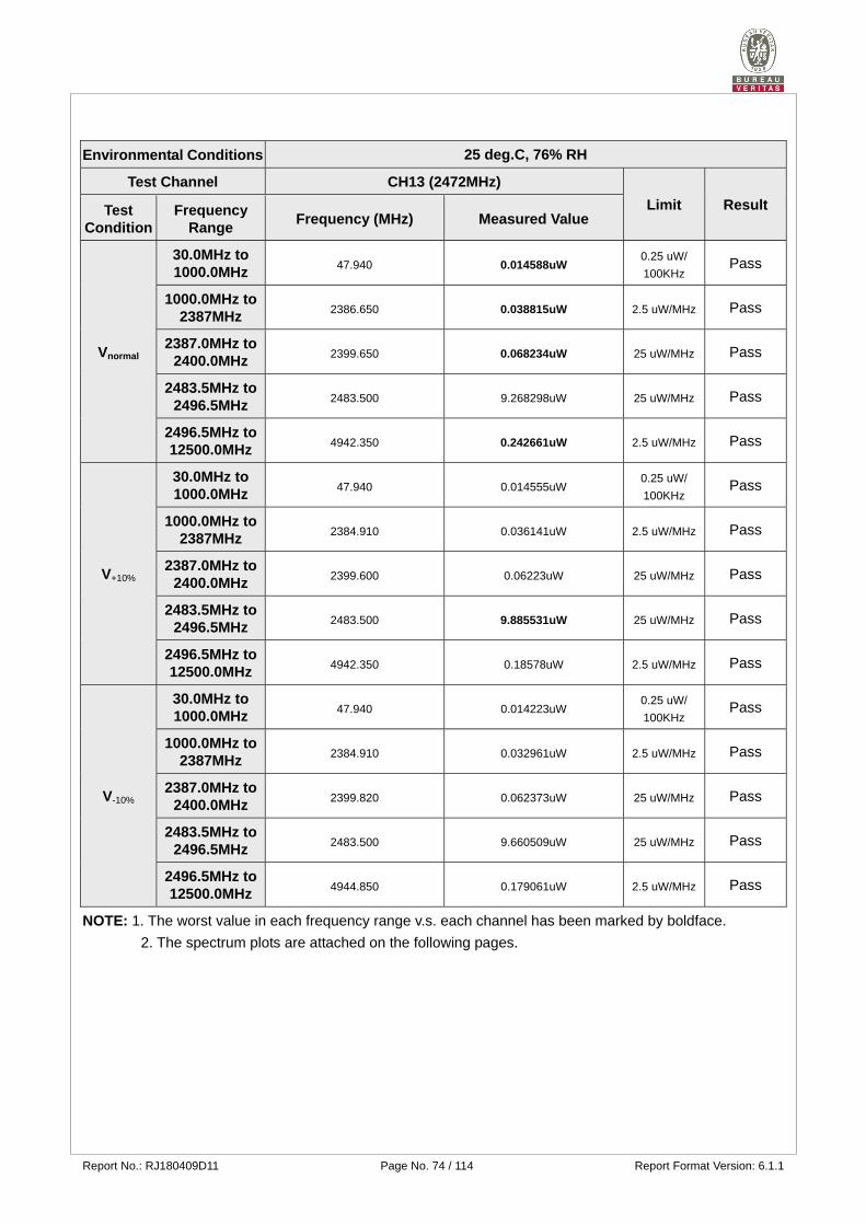
Report No.: RJ180409D11 Page No. 74 / 114 Report Format Version: 6.1.1
Environmental Conditions 25 deg.C, 76% RH
Test Channel CH13 (2472MHz)
Limit Result Test Condition
Frequency Range
Frequency (MHz) Measured Value
Vnormal
30.0MHz to 1000.0MHz
47.940 0.014588uW 0.25 uW/
100KHz Pass
1000.0MHz to 2387MHz
2386.650 0.038815uW 2.5 uW/MHz Pass
2387.0MHz to 2400.0MHz
2399.650 0.068234uW 25 uW/MHz Pass
2483.5MHz to 2496.5MHz
2483.500 9.268298uW 25 uW/MHz Pass
2496.5MHz to 12500.0MHz
4942.350 0.242661uW 2.5 uW/MHz Pass
V+10%
30.0MHz to 1000.0MHz
47.940 0.014555uW 0.25 uW/
100KHz Pass
1000.0MHz to 2387MHz
2384.910 0.036141uW 2.5 uW/MHz Pass
2387.0MHz to 2400.0MHz
2399.600 0.06223uW 25 uW/MHz Pass
2483.5MHz to 2496.5MHz
2483.500 9.885531uW 25 uW/MHz Pass
2496.5MHz to 12500.0MHz
4942.350 0.18578uW 2.5 uW/MHz Pass
V-10%
30.0MHz to 1000.0MHz
47.940 0.014223uW 0.25 uW/
100KHz Pass
1000.0MHz to 2387MHz
2384.910 0.032961uW 2.5 uW/MHz Pass
2387.0MHz to 2400.0MHz
2399.820 0.062373uW 25 uW/MHz Pass
2483.5MHz to 2496.5MHz
2483.500 9.660509uW 25 uW/MHz Pass
2496.5MHz to 12500.0MHz
4944.850 0.179061uW 2.5 uW/MHz Pass
NOTE: 1. The worst value in each frequency range v.s. each channel has been marked by boldface.
2. The spectrum plots are attached on the following pages.
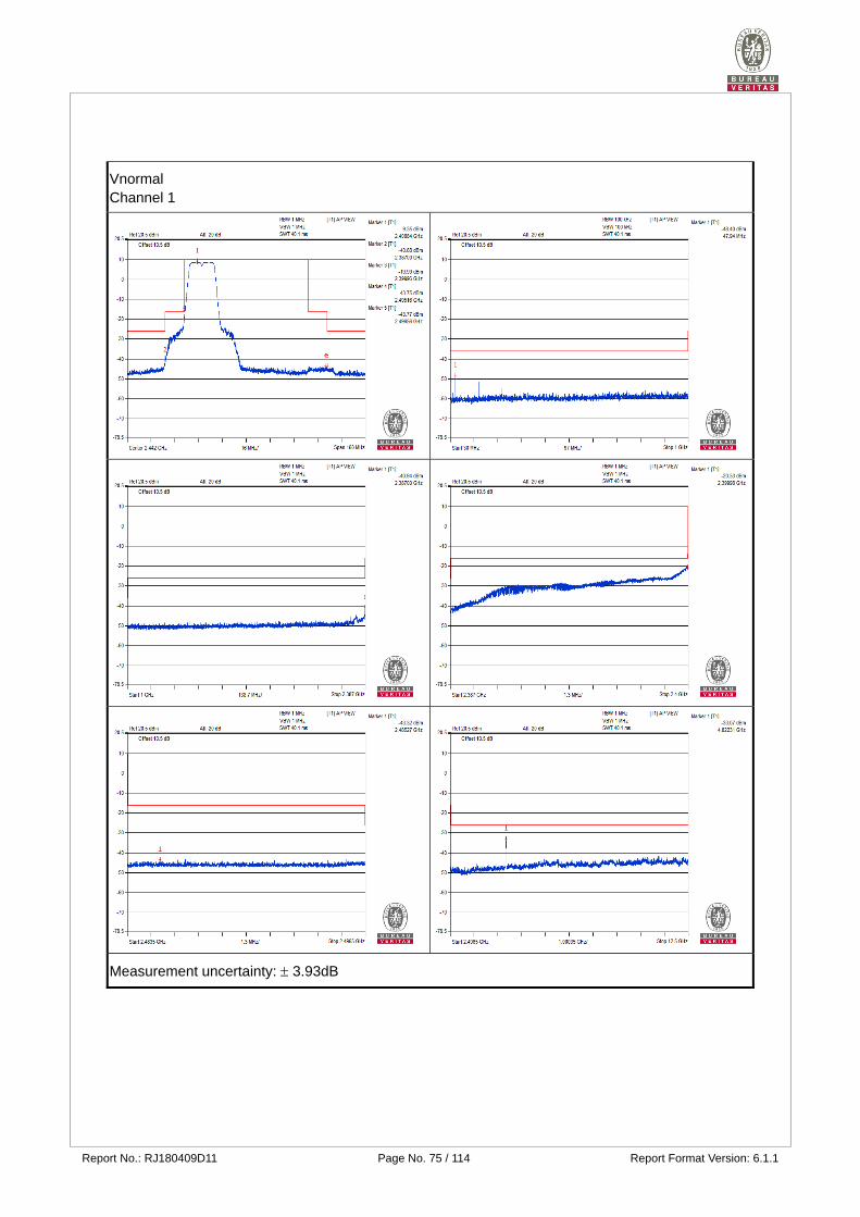
Report No.: RJ180409D11 Page No. 75 / 114 Report Format Version: 6.1.1
Vnormal Channel 1
Measurement uncertainty: 3.93dB

Report No.: RJ180409D11 Page No. 76 / 114 Report Format Version: 6.1.1
Vnormal Channel 7
Measurement uncertainty: 3.93dB

Report No.: RJ180409D11 Page No. 77 / 114 Report Format Version: 6.1.1
Vnormal Channel 13
Measurement uncertainty: 3.93dB
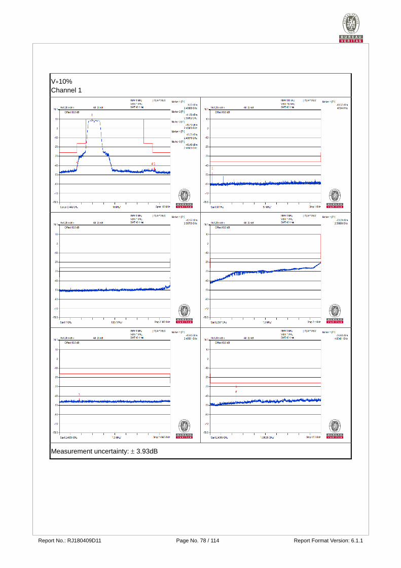
Report No.: RJ180409D11 Page No. 78 / 114 Report Format Version: 6.1.1
V+10% Channel 1
Measurement uncertainty: 3.93dB
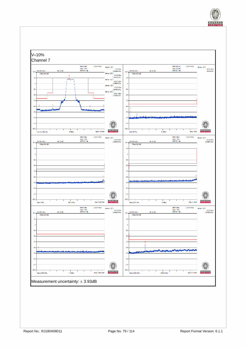
Report No.: RJ180409D11 Page No. 79 / 114 Report Format Version: 6.1.1
V+10% Channel 7
Measurement uncertainty: 3.93dB
Report No.: RJ180409D11 Page No. 80 / 114 Report Format Version: 6.1.1
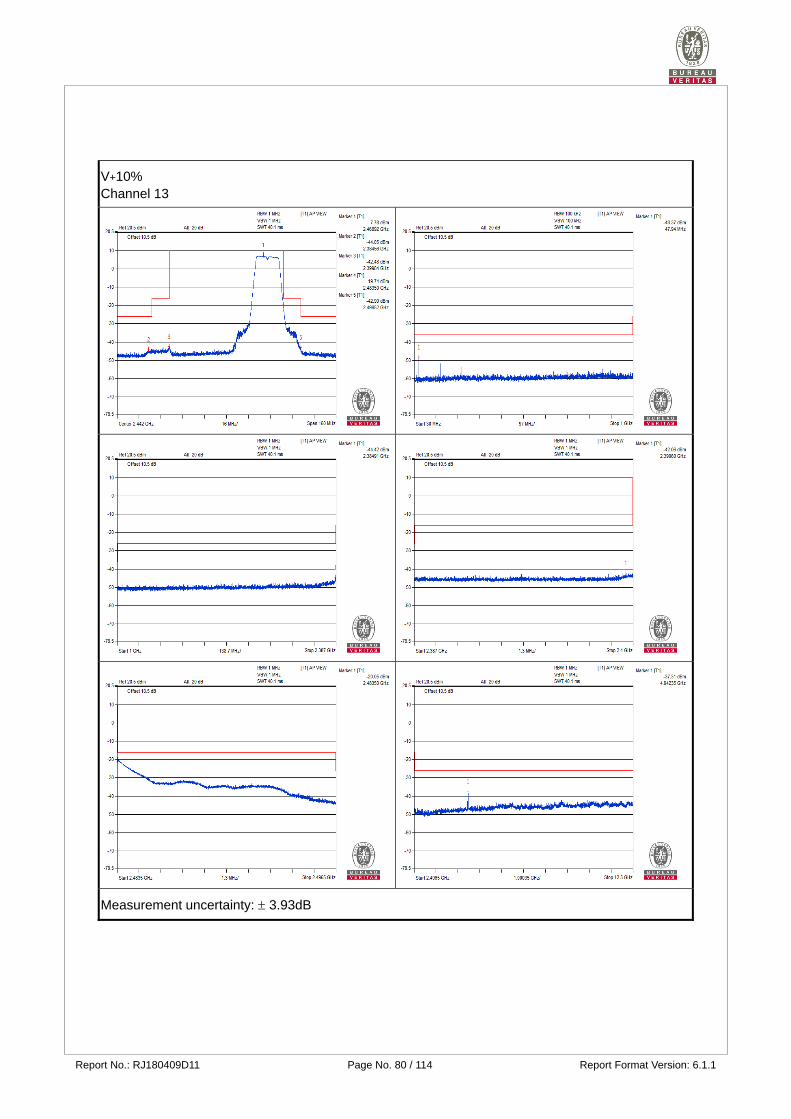
V+10% Channel 13
Measurement uncertainty: 3.93dB
Report No.: RJ180409D11 Page No. 81 / 114 Report Format Version: 6.1.1
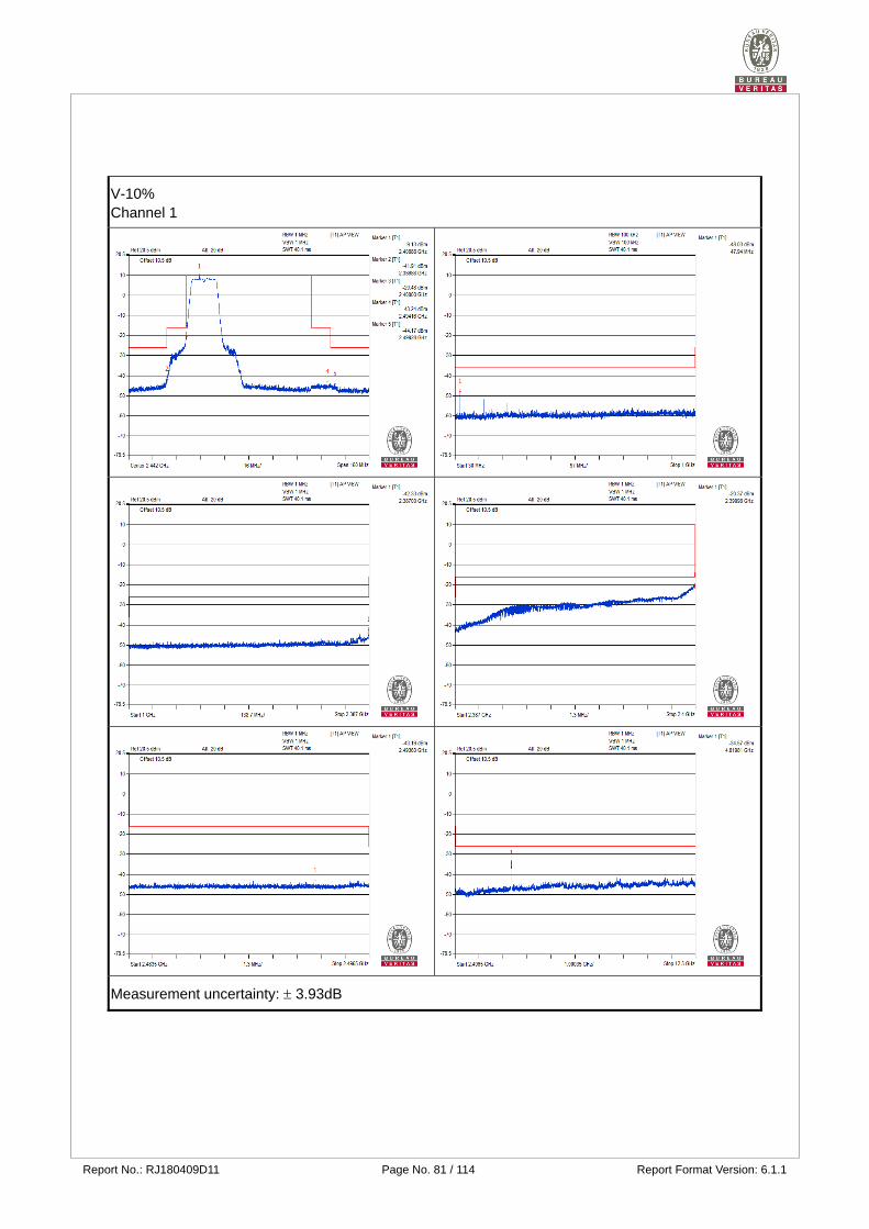
V-10% Channel 1
Measurement uncertainty: 3.93dB
Report No.: RJ180409D11 Page No. 82 / 114 Report Format Version: 6.1.1
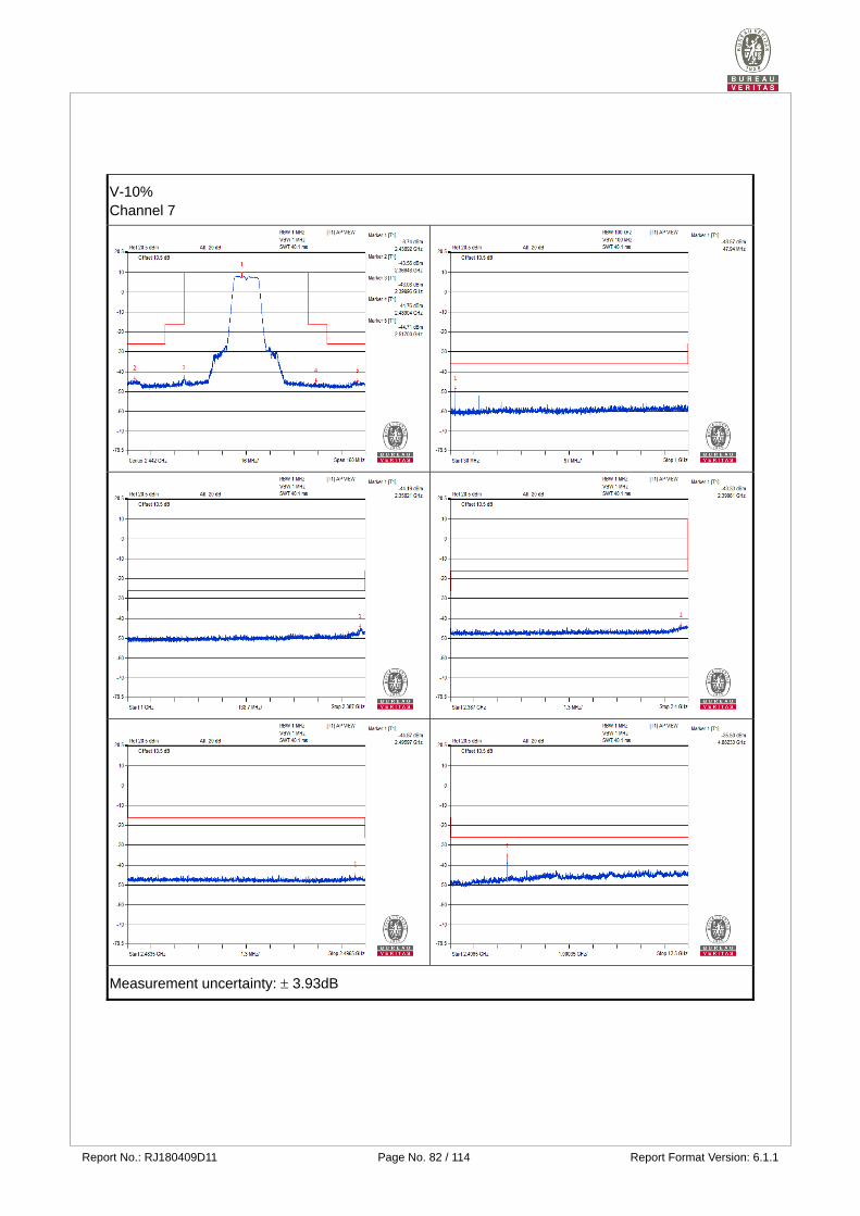
V-10% Channel 7
Measurement uncertainty: 3.93dB
Report No.: RJ180409D11 Page No. 83 / 114 Report Format Version: 6.1.1
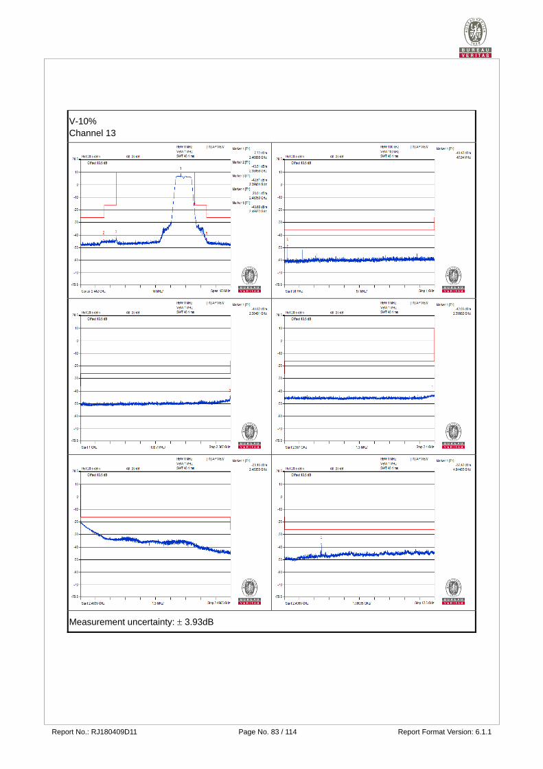
V-10% Channel 13
Measurement uncertainty: 3.93dB
Report No.: RJ180409D11 Page No. 84 / 114 Report Format Version: 6.1.1
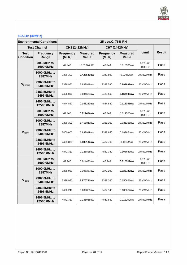
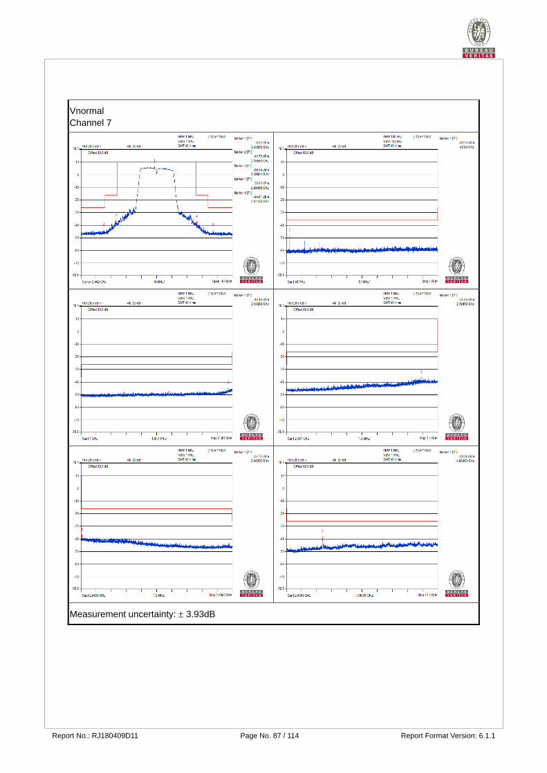
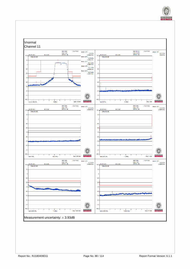
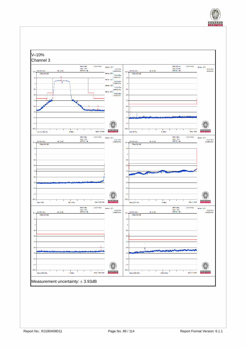
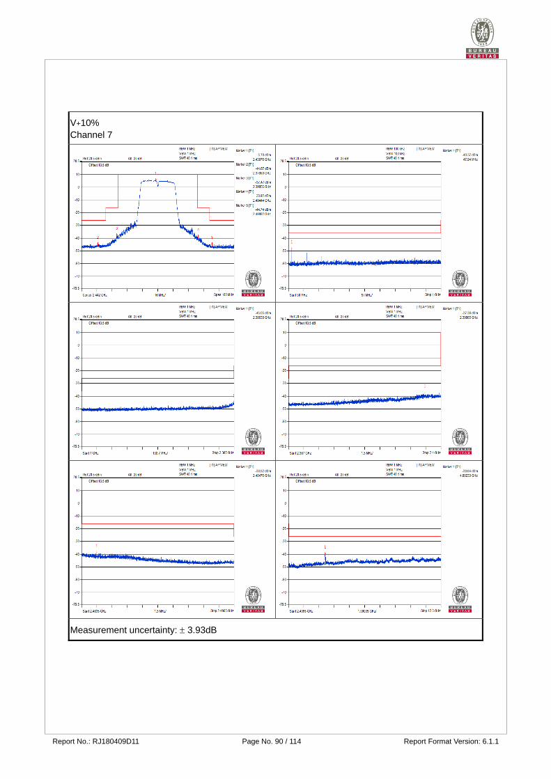
802.11n (40MHz)
Environmental Conditions 25 deg.C, 76% RH
Test Channel CH3 (2422MHz) CH7 (2442MHz)
Limit Result Test Condition
Frequency Range
Frequency (MHz)
Measured Value
Frequency (MHz)
Measured Value
Vnormal
30.0MHz to 1000.0MHz
47.940 0.01374uW 47.940 0.013366uW 0.25 uW/
100KHz Pass
1000.0MHz to 2387MHz
2386.300 0.428549uW 2349.890 0.03062uW 2.5 uW/MHz Pass
2387.0MHz to 2400.0MHz
2399.950 2.837919uW 2398.590 0.197697uW 25 uW/MHz Pass
2483.5MHz to 2496.5MHz
2496.090 0.034674uW 2483.560 0.167109uW 25 uW/MHz Pass
2496.5MHz to 12500.0MHz
4844.820 0.148252uW 4884.830 0.115345uW 2.5 uW/MHz Pass
V+10%
30.0MHz to 1000.0MHz
47.940 0.014454uW 47.940 0.014555uW 0.25 uW/
100KHz Pass
1000.0MHz to 2387MHz
2386.300 0.415911uW 2386.300 0.031261uW 2.5 uW/MHz Pass
2387.0MHz to 2400.0MHz
2400.000 2.837919uW 2398.650 0.183654uW 25 uW/MHz Pass
2483.5MHz to 2496.5MHz
2495.830 0.038194uW 2484.760 0.13122uW 25 uW/MHz Pass
2496.5MHz to 12500.0MHz
4842.320 0.128825uW 4882.330 0.108643uW 2.5 uW/MHz Pass
V-10%
30.0MHz to 1000.0MHz
47.940 0.014421uW 47.940 0.015311uW 0.25 uW/
100KHz Pass
1000.0MHz to 2387MHz
2385.950 0.395367uW 2377.290 0.035727uW 2.5 uW/MHz Pass
2387.0MHz to 2400.0MHz
2399.980 2.870781uW 2398.260 0.150661uW 25 uW/MHz Pass
2483.5MHz to 2496.5MHz
2496.240 0.032885uW 2484.140 0.105682uW 25 uW/MHz Pass
2496.5MHz to 12500.0MHz
4842.320 0.138038uW 4869.830 0.112202uW 2.5 uW/MHz Pass
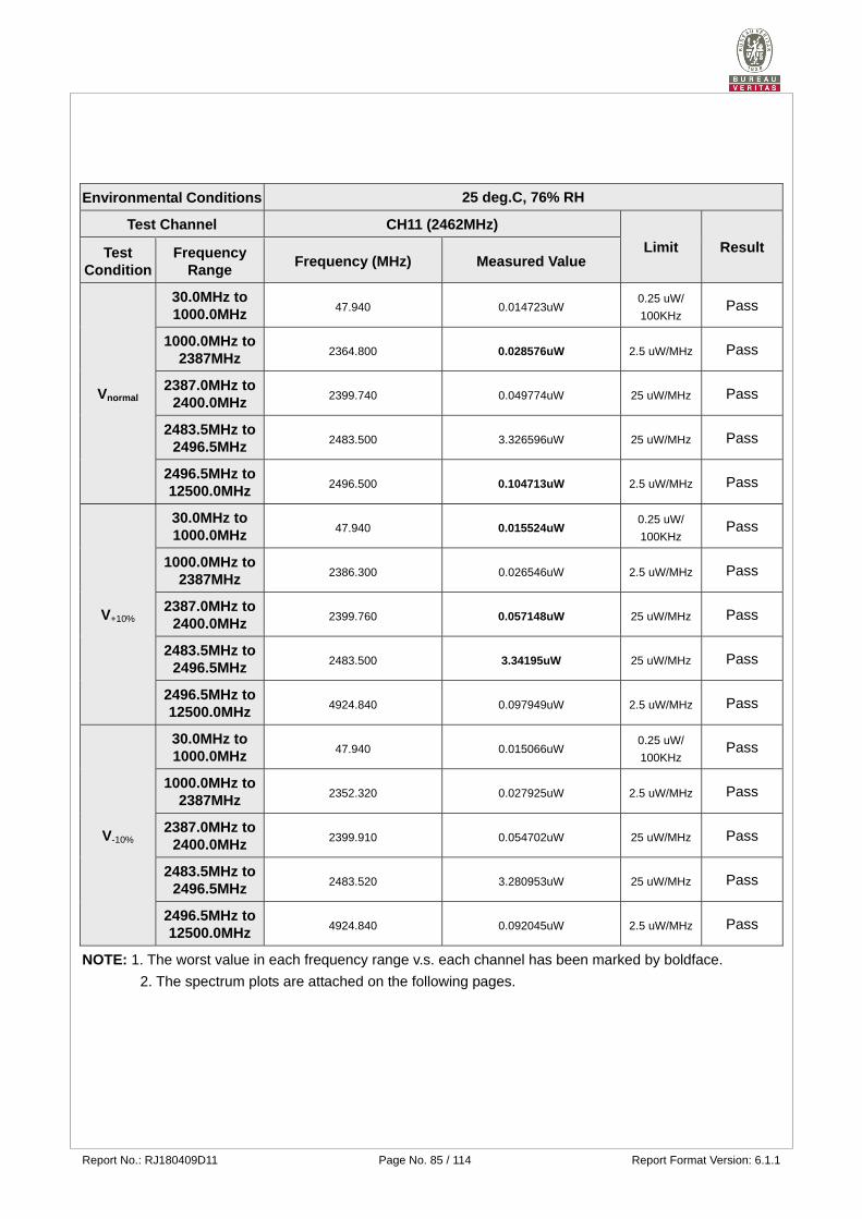
Report No.: RJ180409D11 Page No. 85 / 114 Report Format Version: 6.1.1
Environmental Conditions 25 deg.C, 76% RH
Test Channel CH11 (2462MHz)
Limit Result Test Condition
Frequency Range
Frequency (MHz) Measured Value
Vnormal
30.0MHz to 1000.0MHz
47.940 0.014723uW 0.25 uW/
100KHz Pass
1000.0MHz to 2387MHz
2364.800 0.028576uW 2.5 uW/MHz Pass
2387.0MHz to 2400.0MHz
2399.740 0.049774uW 25 uW/MHz Pass
2483.5MHz to 2496.5MHz
2483.500 3.326596uW 25 uW/MHz Pass
2496.5MHz to 12500.0MHz
2496.500 0.104713uW 2.5 uW/MHz Pass
V+10%
30.0MHz to 1000.0MHz
47.940 0.015524uW 0.25 uW/
100KHz Pass
1000.0MHz to 2387MHz
2386.300 0.026546uW 2.5 uW/MHz Pass
2387.0MHz to 2400.0MHz
2399.760 0.057148uW 25 uW/MHz Pass
2483.5MHz to 2496.5MHz
2483.500 3.34195uW 25 uW/MHz Pass
2496.5MHz to 12500.0MHz
4924.840 0.097949uW 2.5 uW/MHz Pass
V-10%
30.0MHz to 1000.0MHz
47.940 0.015066uW 0.25 uW/
100KHz Pass
1000.0MHz to 2387MHz
2352.320 0.027925uW 2.5 uW/MHz Pass
2387.0MHz to 2400.0MHz
2399.910 0.054702uW 25 uW/MHz Pass
2483.5MHz to 2496.5MHz
2483.520 3.280953uW 25 uW/MHz Pass
2496.5MHz to 12500.0MHz
4924.840 0.092045uW 2.5 uW/MHz Pass
NOTE: 1. The worst value in each frequency range v.s. each channel has been marked by boldface.
2. The spectrum plots are attached on the following pages.
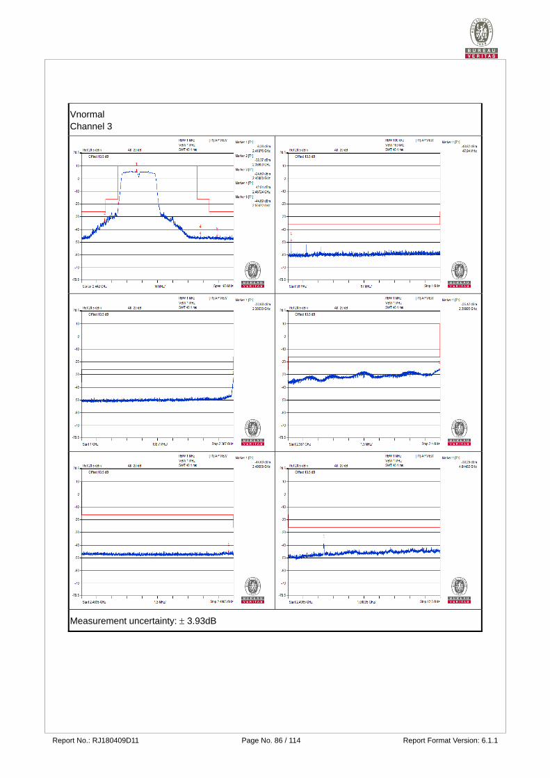
Report No.: RJ180409D11 Page No. 86 / 114 Report Format Version: 6.1.1
Vnormal Channel 3
Measurement uncertainty: 3.93dB
Report No.: RJ180409D11 Page No. 87 / 114 Report Format Version: 6.1.1
Vnormal Channel 7
Measurement uncertainty: 3.93dB
Report No.: RJ180409D11 Page No. 88 / 114 Report Format Version: 6.1.1
Vnormal Channel 11
Measurement uncertainty: 3.93dB
Report No.: RJ180409D11 Page No. 89 / 114 Report Format Version: 6.1.1
V+10% Channel 3
Measurement uncertainty: 3.93dB
Report No.: RJ180409D11 Page No. 90 / 114 Report Format Version: 6.1.1
V+10% Channel 7
Measurement uncertainty: 3.93dB
Report No.: RJ180409D11 Page No. 91 / 114 Report Format Version: 6.1.1
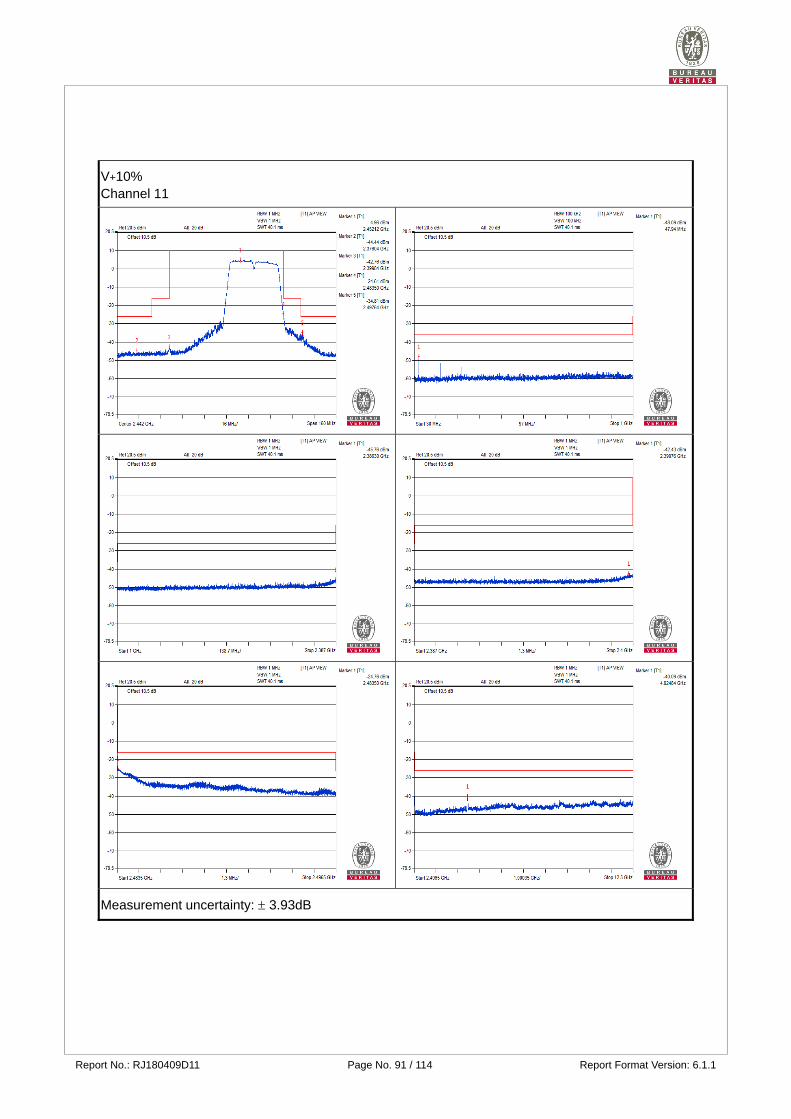
V+10% Channel 11
Measurement uncertainty: 3.93dB
Report No.: RJ180409D11 Page No. 92 / 114 Report Format Version: 6.1.1
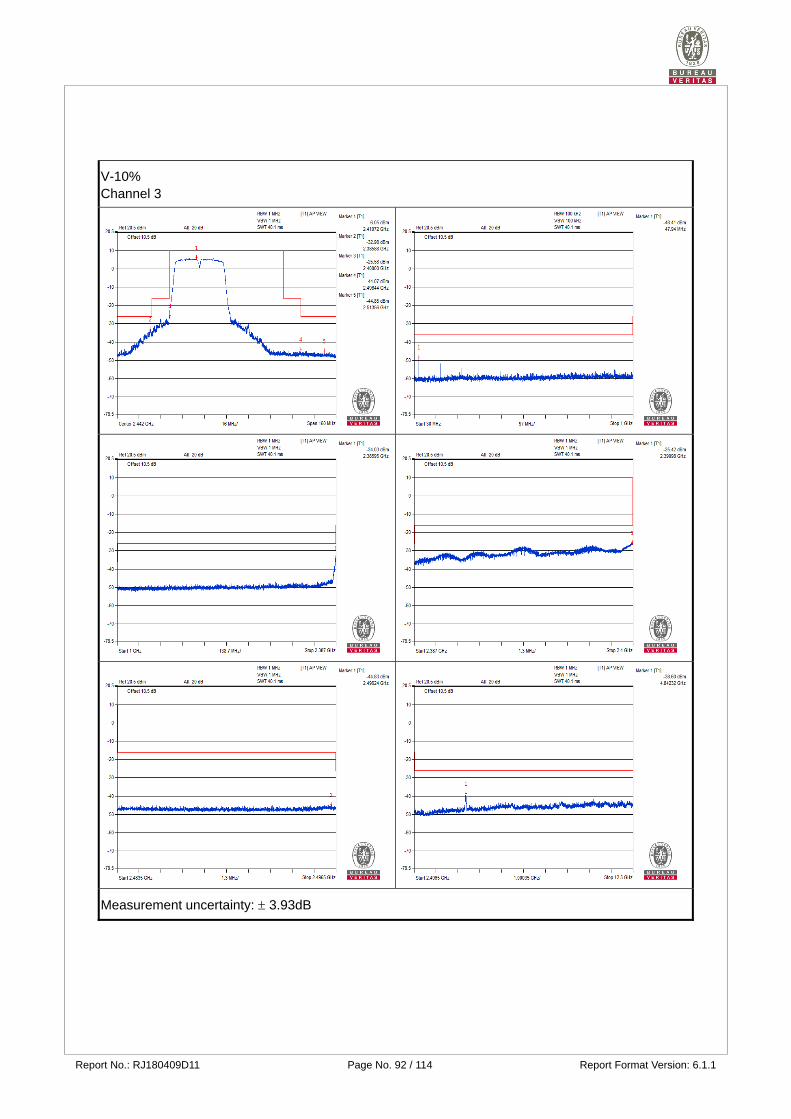
V-10% Channel 3
Measurement uncertainty: 3.93dB

Report No.: RJ180409D11 Page No. 93 / 114 Report Format Version: 6.1.1
V-10% Channel 7
Measurement uncertainty: 3.93dB
Report No.: RJ180409D11 Page No. 94 / 114 Report Format Version: 6.1.1
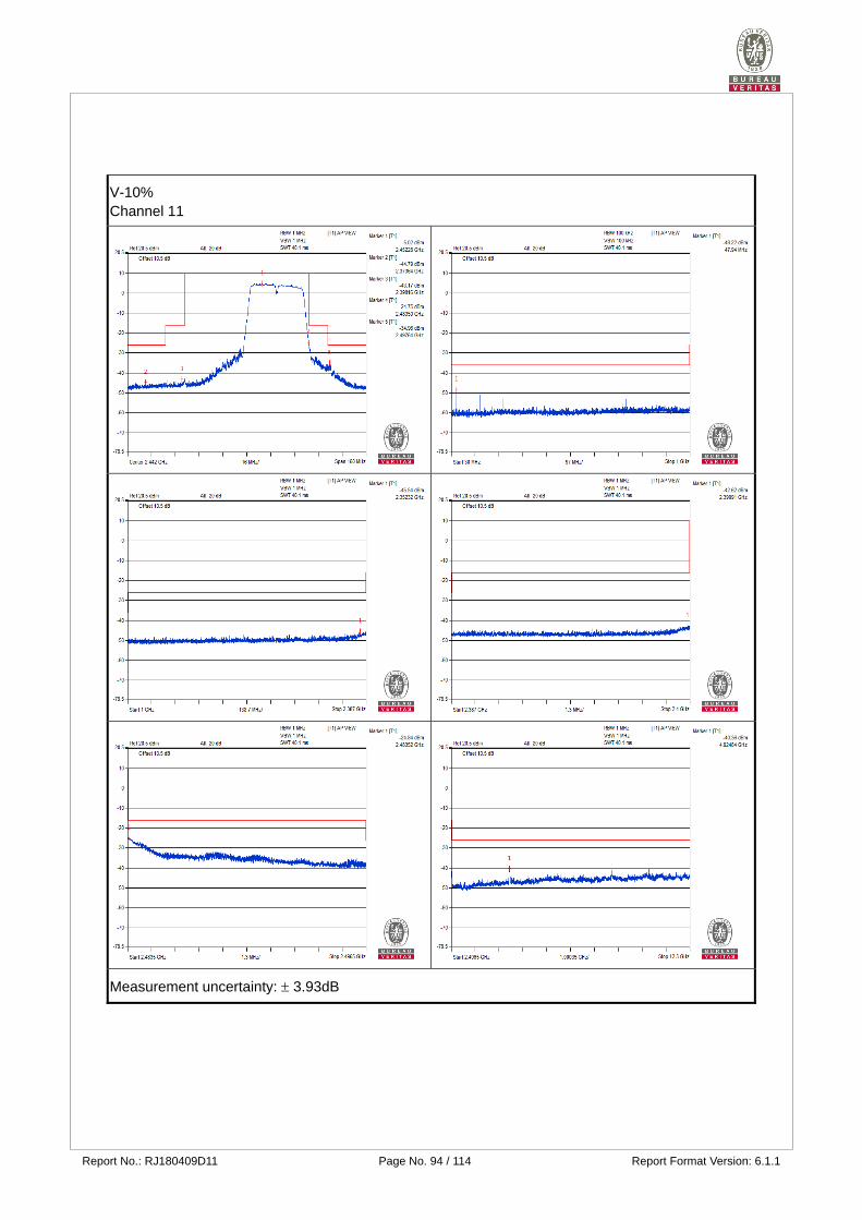
V-10% Channel 11
Measurement uncertainty: 3.93dB
Report No.: RJ180409D11 Page No. 95 / 114 Report Format Version: 6.1.1
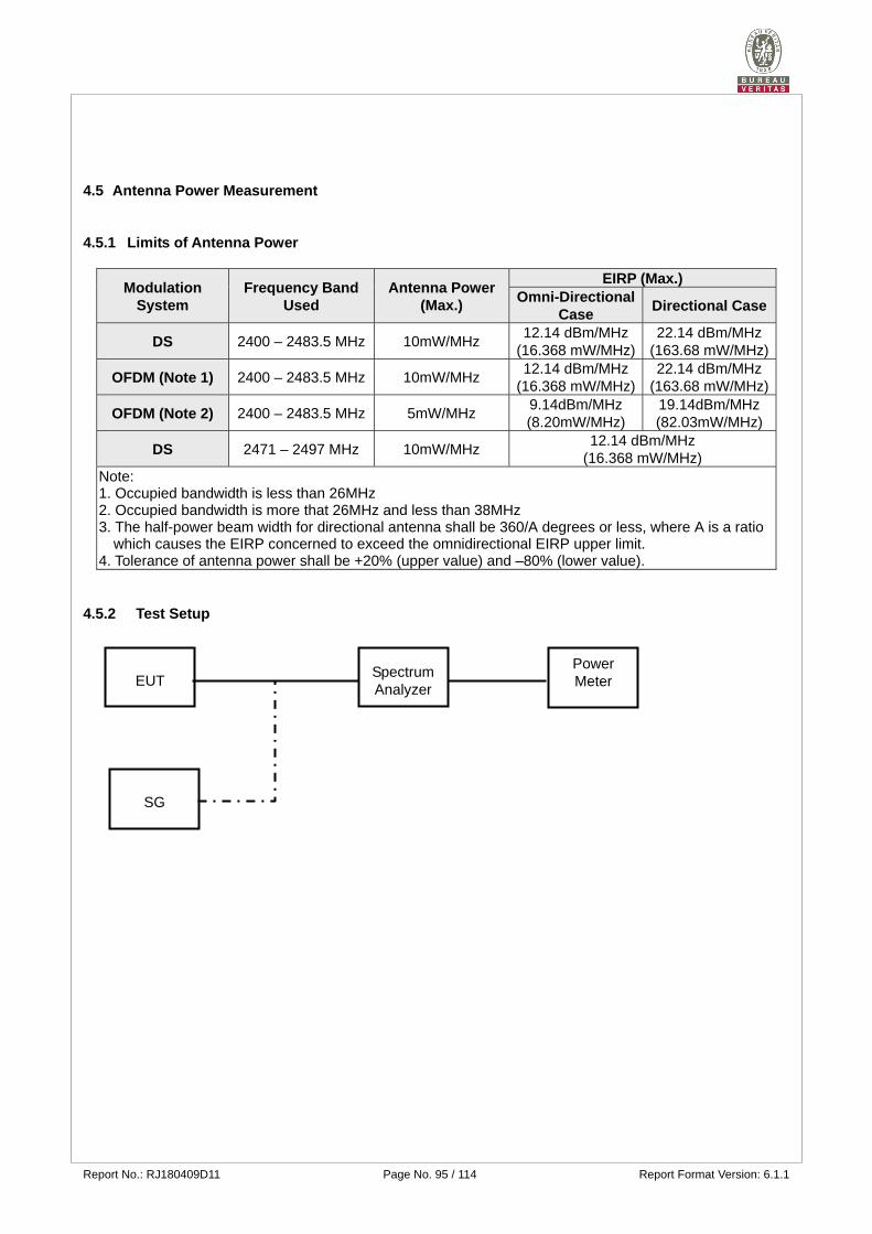
4.5 Antenna Power Measurement
4.5.1 Limits of Antenna Power
Modulation System
Frequency Band Used
Antenna Power (Max.)
EIRP (Max.) Omni-Directional
Case Directional Case
DS 2400 – 2483.5 MHz 10mW/MHz 12.14 dBm/MHz
(16.368 mW/MHz) 22.14 dBm/MHz
(163.68 mW/MHz)
OFDM (Note 1) 2400 – 2483.5 MHz 10mW/MHz 12.14 dBm/MHz
(16.368 mW/MHz) 22.14 dBm/MHz
(163.68 mW/MHz)
OFDM (Note 2) 2400 – 2483.5 MHz 5mW/MHz 9.14dBm/MHz (8.20mW/MHz)
19.14dBm/MHz (82.03mW/MHz)
DS 2471 – 2497 MHz 10mW/MHz 12.14 dBm/MHz
(16.368 mW/MHz) Note: 1. Occupied bandwidth is less than 26MHz 2. Occupied bandwidth is more that 26MHz and less than 38MHz 3. The half-power beam width for directional antenna shall be 360/A degrees or less, where A is a ratio
which causes the EIRP concerned to exceed the omnidirectional EIRP upper limit. 4. Tolerance of antenna power shall be +20% (upper value) and –80% (lower value).
4.5.2 Test Setup
EUT Spectrum Analyzer
SG
Power Meter
Report No.: RJ180409D11 Page No. 96 / 114 Report Format Version: 6.1.1
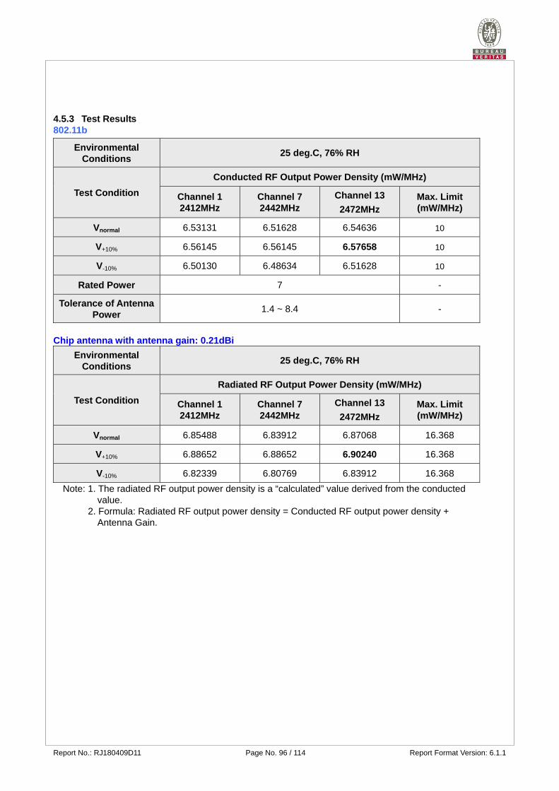
4.5.3 Test Results 802.11b
Environmental Conditions
25 deg.C, 76% RH
Test Condition
Conducted RF Output Power Density (mW/MHz)
Channel 1 2412MHz
Channel 7 2442MHz
Channel 13
2472MHz Max. Limit (mW/MHz)
Vnormal 6.53131 6.51628 6.54636 10
V+10% 6.56145 6.56145 6.57658 10
V-10% 6.50130 6.48634 6.51628 10
Rated Power 7 -
Tolerance of Antenna Power
1.4 ~ 8.4 -
Chip antenna with antenna gain: 0.21dBi
Environmental Conditions
25 deg.C, 76% RH
Test Condition
Radiated RF Output Power Density (mW/MHz)
Channel 1 2412MHz
Channel 7 2442MHz
Channel 13
2472MHz Max. Limit (mW/MHz)
Vnormal 6.85488 6.83912 6.87068 16.368
V+10% 6.88652 6.88652 6.90240 16.368
V-10% 6.82339 6.80769 6.83912 16.368
Note: 1. The radiated RF output power density is a “calculated” value derived from the conducted value.
2. Formula: Radiated RF output power density = Conducted RF output power density +
Antenna Gain.
Report No.: RJ180409D11 Page No. 97 / 114 Report Format Version: 6.1.1
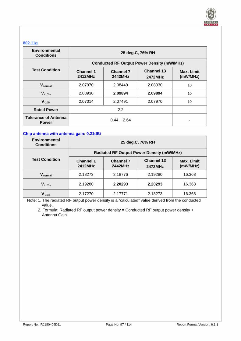
802.11g
Environmental Conditions
25 deg.C, 76% RH
Test Condition
Conducted RF Output Power Density (mW/MHz)
Channel 1 2412MHz
Channel 7 2442MHz
Channel 13
2472MHz Max. Limit (mW/MHz)
Vnormal 2.07970 2.08449 2.08930 10
V+10% 2.08930 2.09894 2.09894 10
V-10% 2.07014 2.07491 2.07970 10
Rated Power 2.2 -
Tolerance of Antenna Power
0.44 ~ 2.64 -
Chip antenna with antenna gain: 0.21dBi
Environmental Conditions
25 deg.C, 76% RH
Test Condition
Radiated RF Output Power Density (mW/MHz)
Channel 1 2412MHz
Channel 7 2442MHz
Channel 13
2472MHz Max. Limit (mW/MHz)
Vnormal 2.18273 2.18776 2.19280 16.368
V+10% 2.19280 2.20293 2.20293 16.368
V-10% 2.17270 2.17771 2.18273 16.368
Note: 1. The radiated RF output power density is a “calculated” value derived from the conducted value.
2. Formula: Radiated RF output power density = Conducted RF output power density +
Antenna Gain.

Report No.: RJ180409D11 Page No. 98 / 114 Report Format Version: 6.1.1
802.11n (20MHz)
Environmental Conditions
25 deg.C, 76% RH
Test Condition
Conducted RF Output Power Density (mW/MHz)
Channel 1 2412MHz
Channel 7 2442MHz
Channel 13
2472MHz Max. Limit (mW/MHz)
Vnormal 2.54097 2.52930 2.55859 10
V+10% 2.55859 2.54097 2.57040 10
V-10% 2.52930 2.51189 2.54683 10
Rated Power 3 -
Tolerance of Antenna Power
0.6 ~ 3.6 -
Chip antenna with antenna gain: 0.21dBi
Environmental Conditions
25 deg.C, 76% RH
Test Condition
Radiated RF Output Power Density (mW/MHz)
Channel 1 2412MHz
Channel 7 2442MHz
Channel 13
2472MHz Max. Limit (mW/MHz)
Vnormal 2.66686 2.65461 2.68534 16.368
V+10% 2.68534 2.66686 2.69774 16.368
V-10% 2.65461 2.63633 2.67301 16.368
Note: 1. The radiated RF output power density is a “calculated” value derived from the conducted value.
2. Formula: Radiated RF output power density = Conducted RF output power density +
Antenna Gain.
Report No.: RJ180409D11 Page No. 99 / 114 Report Format Version: 6.1.1
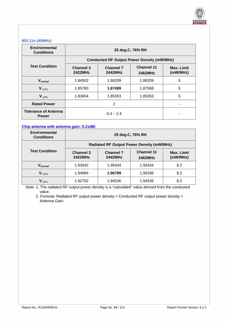
802.11n (40MHz)
Environmental Conditions
25 deg.C, 76% RH
Test Condition
Conducted RF Output Power Density (mW/MHz)
Channel 3 2422MHz
Channel 7 2442MHz
Channel 11
2462MHz Max. Limit (mW/MHz)
Vnormal 1.84502 1.86209 1.86209 5
V+10% 1.85780 1.87499 1.87068 5
V-10% 1.83654 1.85353 1.85353 5
Rated Power 2 -
Tolerance of Antenna Power
0.4 ~ 2.4 -
Chip antenna with antenna gain: 0.21dBi
Environmental Conditions
25 deg.C, 76% RH
Test Condition
Radiated RF Output Power Density (mW/MHz)
Channel 3 2422MHz
Channel 7 2442MHz
Channel 11
2462MHz Max. Limit (mW/MHz)
Vnormal 1.93642 1.95434 1.95434 8.2
V+10% 1.94984 1.96789 1.96336 8.2
V-10% 1.92752 1.94536 1.94536 8.2
Note: 1. The radiated RF output power density is a “calculated” value derived from the conducted value.
2. Formula: Radiated RF output power density = Conducted RF output power density +
Antenna Gain.
Report No.: RJ180409D11 Page No. 100 / 114 Report Format Version: 6.1.1
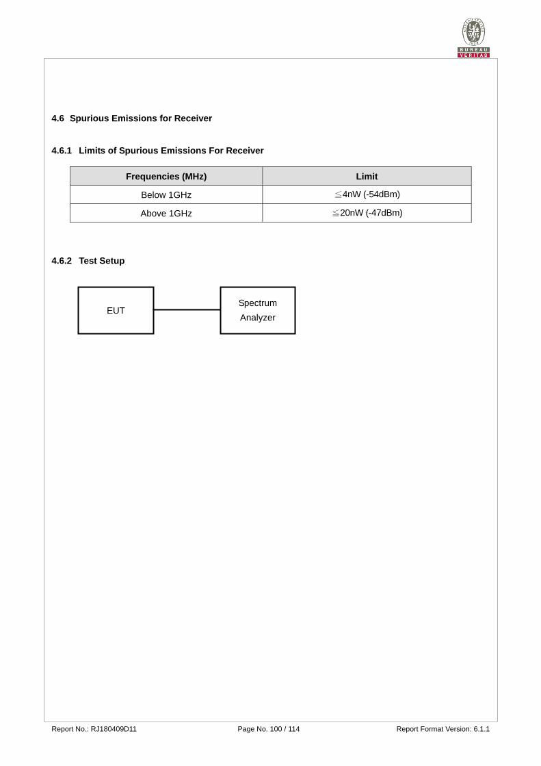
4.6 Spurious Emissions for Receiver
4.6.1 Limits of Spurious Emissions For Receiver
Frequencies (MHz) Limit
Below 1GHz ≦4nW (-54dBm)
Above 1GHz ≦20nW (-47dBm)
4.6.2 Test Setup
EUT Spectrum
Analyzer
Report No.: RJ180409D11 Page No. 101 / 114 Report Format Version: 6.1.1
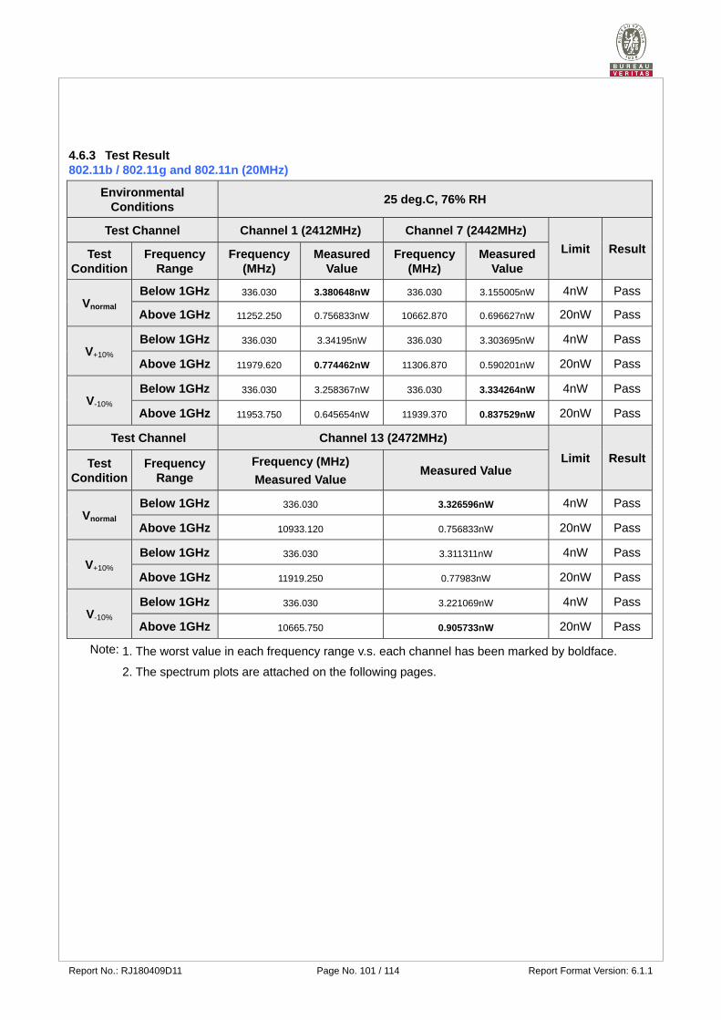
4.6.3 Test Result 802.11b / 802.11g and 802.11n (20MHz)
Environmental Conditions
25 deg.C, 76% RH
Test Channel Channel 1 (2412MHz) Channel 7 (2442MHz)
Limit ResultTest Condition
Frequency Range
Frequency (MHz)
Measured Value
Frequency (MHz)
Measured Value
Vnormal Below 1GHz 336.030 3.380648nW 336.030 3.155005nW 4nW Pass
Above 1GHz 11252.250 0.756833nW 10662.870 0.696627nW 20nW Pass
V+10% Below 1GHz 336.030 3.34195nW 336.030 3.303695nW 4nW Pass
Above 1GHz 11979.620 0.774462nW 11306.870 0.590201nW 20nW Pass
V-10% Below 1GHz 336.030 3.258367nW 336.030 3.334264nW 4nW Pass
Above 1GHz 11953.750 0.645654nW 11939.370 0.837529nW 20nW Pass
Test Channel Channel 13 (2472MHz)
Limit ResultTest Condition
Frequency Range
Frequency (MHz)
Measured Value Measured Value
Vnormal Below 1GHz 336.030 3.326596nW 4nW Pass
Above 1GHz 10933.120 0.756833nW 20nW Pass
V+10% Below 1GHz 336.030 3.311311nW 4nW Pass
Above 1GHz 11919.250 0.77983nW 20nW Pass
V-10% Below 1GHz 336.030 3.221069nW 4nW Pass
Above 1GHz 10665.750 0.905733nW 20nW Pass
Note: 1. The worst value in each frequency range v.s. each channel has been marked by boldface.
2. The spectrum plots are attached on the following pages.
Report No.: RJ180409D11 Page No. 102 / 114 Report Format Version: 6.1.1
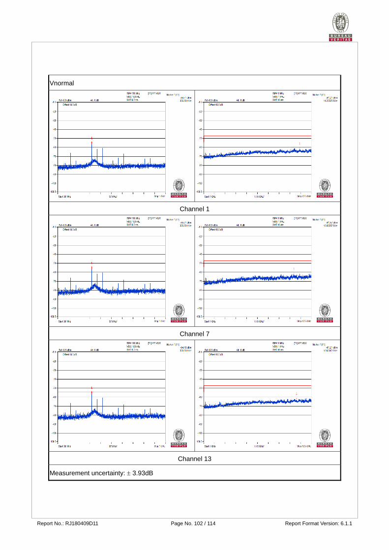
Vnormal
Channel 1
Channel 7
Channel 13
Measurement uncertainty: 3.93dB
Report No.: RJ180409D11 Page No. 103 / 114 Report Format Version: 6.1.1
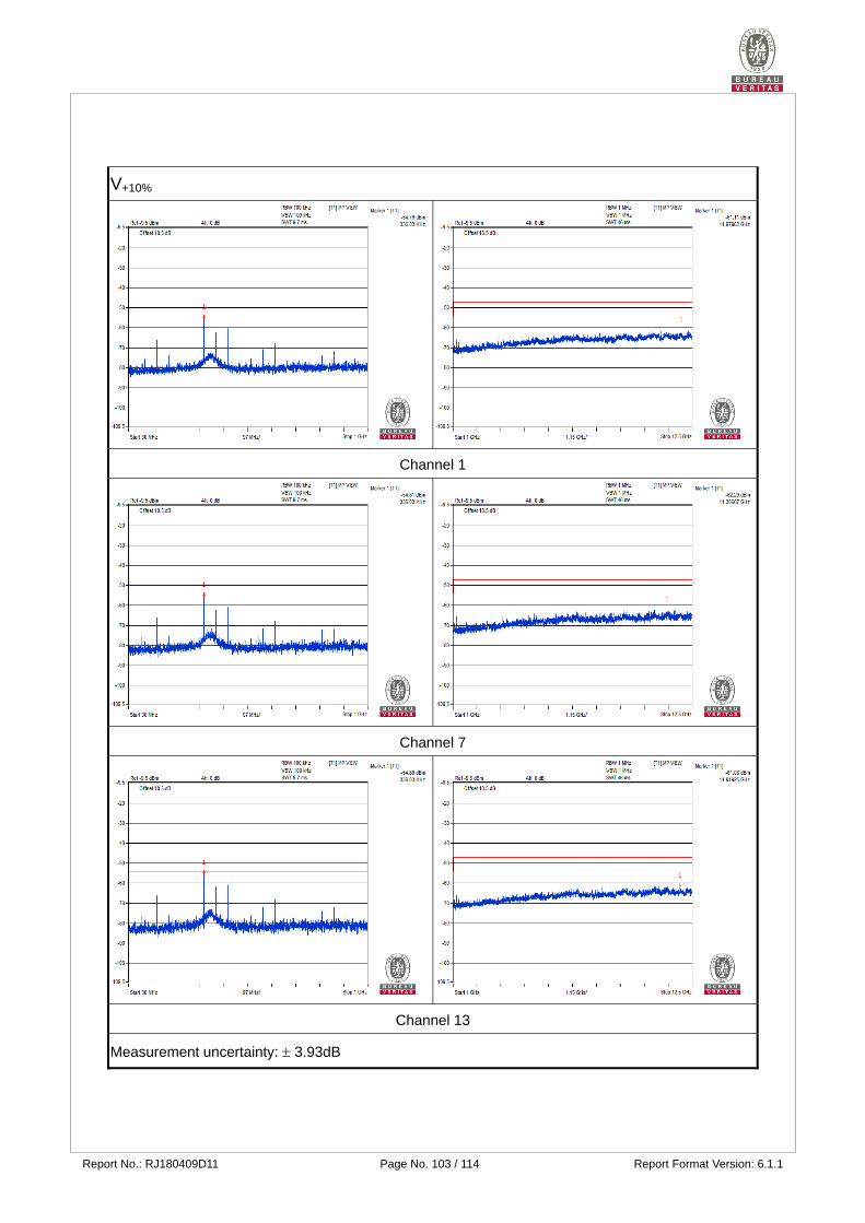
V+10%
Channel 1
Channel 7
Channel 13
Measurement uncertainty: 3.93dB
Report No.: RJ180409D11 Page No. 104 / 114 Report Format Version: 6.1.1
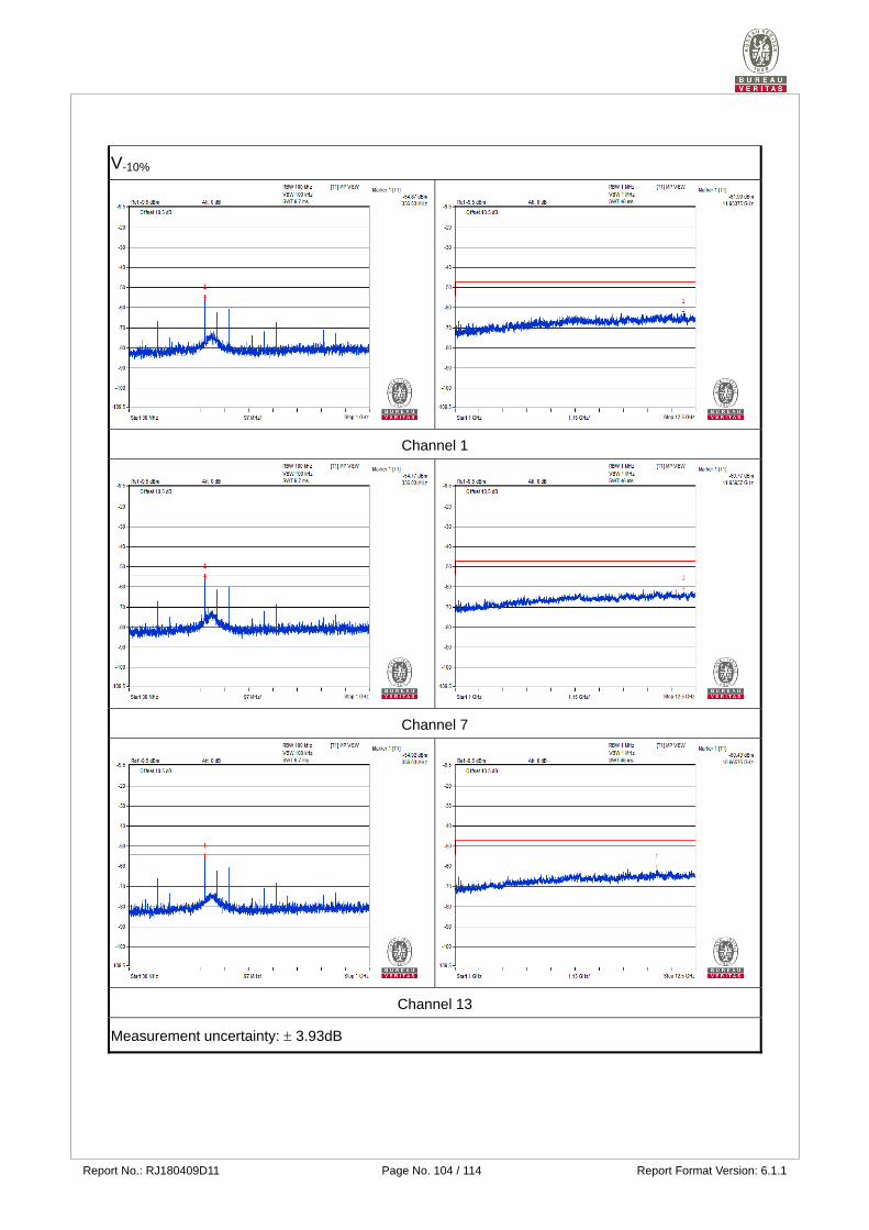
V-10%
Channel 1
Channel 7
Channel 13
Measurement uncertainty: 3.93dB
Report No.: RJ180409D11 Page No. 105 / 114 Report Format Version: 6.1.1
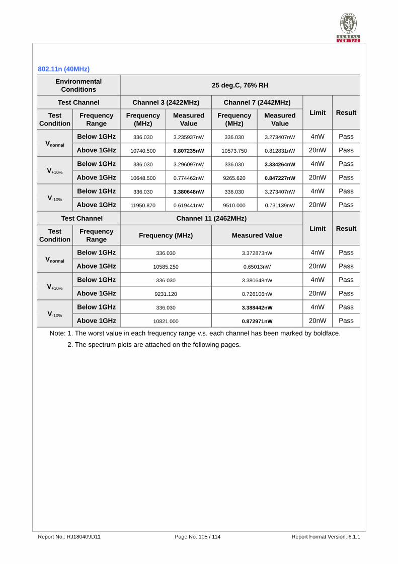
802.11n (40MHz)
Environmental Conditions
25 deg.C, 76% RH
Test Channel Channel 3 (2422MHz) Channel 7 (2442MHz)
Limit ResultTest Condition
Frequency Range
Frequency (MHz)
Measured Value
Frequency (MHz)
Measured Value
Vnormal Below 1GHz 336.030 3.235937nW 336.030 3.273407nW 4nW Pass
Above 1GHz 10740.500 0.807235nW 10573.750 0.812831nW 20nW Pass
V+10% Below 1GHz 336.030 3.296097nW 336.030 3.334264nW 4nW Pass
Above 1GHz 10648.500 0.774462nW 9265.620 0.847227nW 20nW Pass
V-10% Below 1GHz 336.030 3.380648nW 336.030 3.273407nW 4nW Pass
Above 1GHz 11950.870 0.619441nW 9510.000 0.731139nW 20nW Pass
Test Channel Channel 11 (2462MHz)
Limit ResultTest Condition
Frequency Range
Frequency (MHz) Measured Value
Vnormal Below 1GHz 336.030 3.372873nW 4nW Pass
Above 1GHz 10585.250 0.65013nW 20nW Pass
V+10% Below 1GHz 336.030 3.380648nW 4nW Pass
Above 1GHz 9231.120 0.726106nW 20nW Pass
V-10% Below 1GHz 336.030 3.388442nW 4nW Pass
Above 1GHz 10821.000 0.872971nW 20nW Pass
Note: 1. The worst value in each frequency range v.s. each channel has been marked by boldface.
2. The spectrum plots are attached on the following pages.
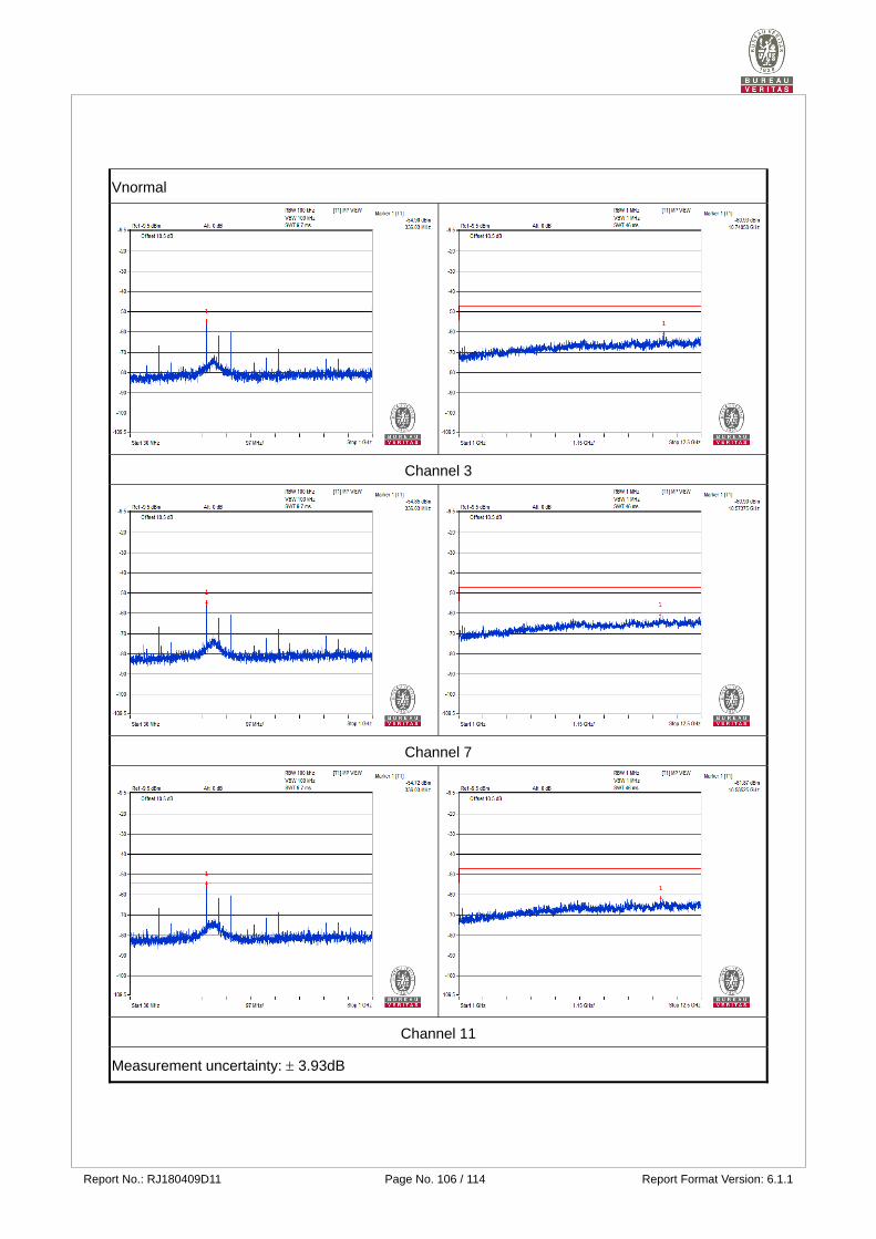
Report No.: RJ180409D11 Page No. 106 / 114 Report Format Version: 6.1.1
Vnormal
Channel 3
Channel 7
Channel 11
Measurement uncertainty: 3.93dB
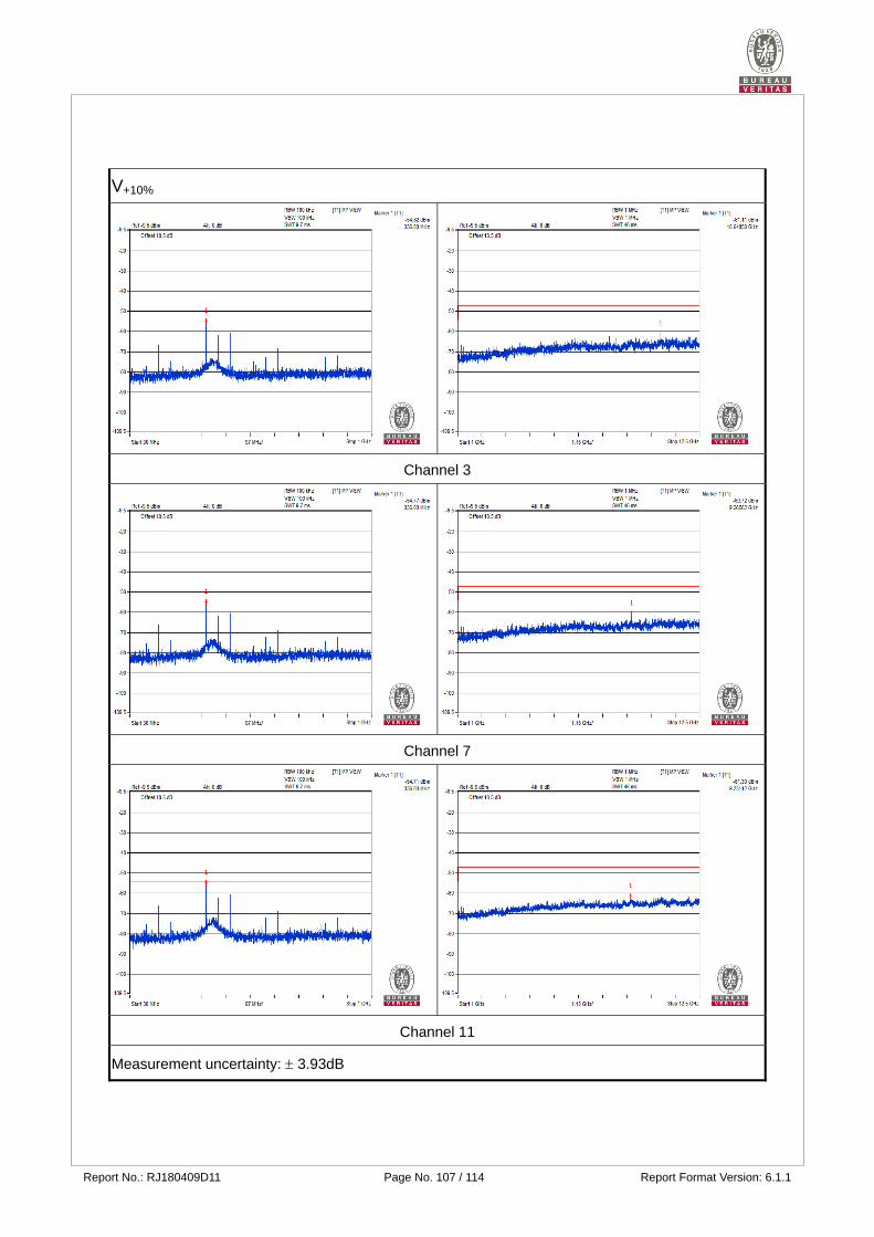
Report No.: RJ180409D11 Page No. 107 / 114 Report Format Version: 6.1.1
V+10%
Channel 3
Channel 7
Channel 11
Measurement uncertainty: 3.93dB
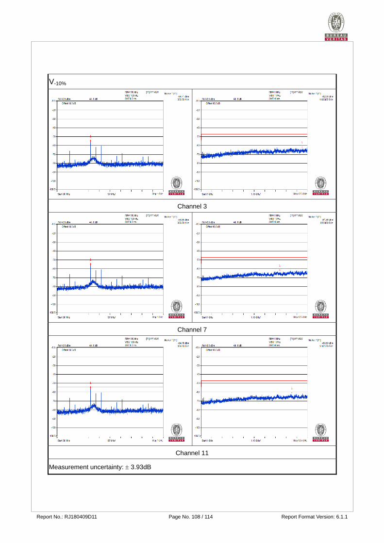
Report No.: RJ180409D11 Page No. 108 / 114 Report Format Version: 6.1.1
V-10%
Channel 3
Channel 7
Channel 11
Measurement uncertainty: 3.93dB
Report No.: RJ180409D11 Page No. 109 / 114 Report Format Version: 6.1.1
4.7 Carrier Sense Capability
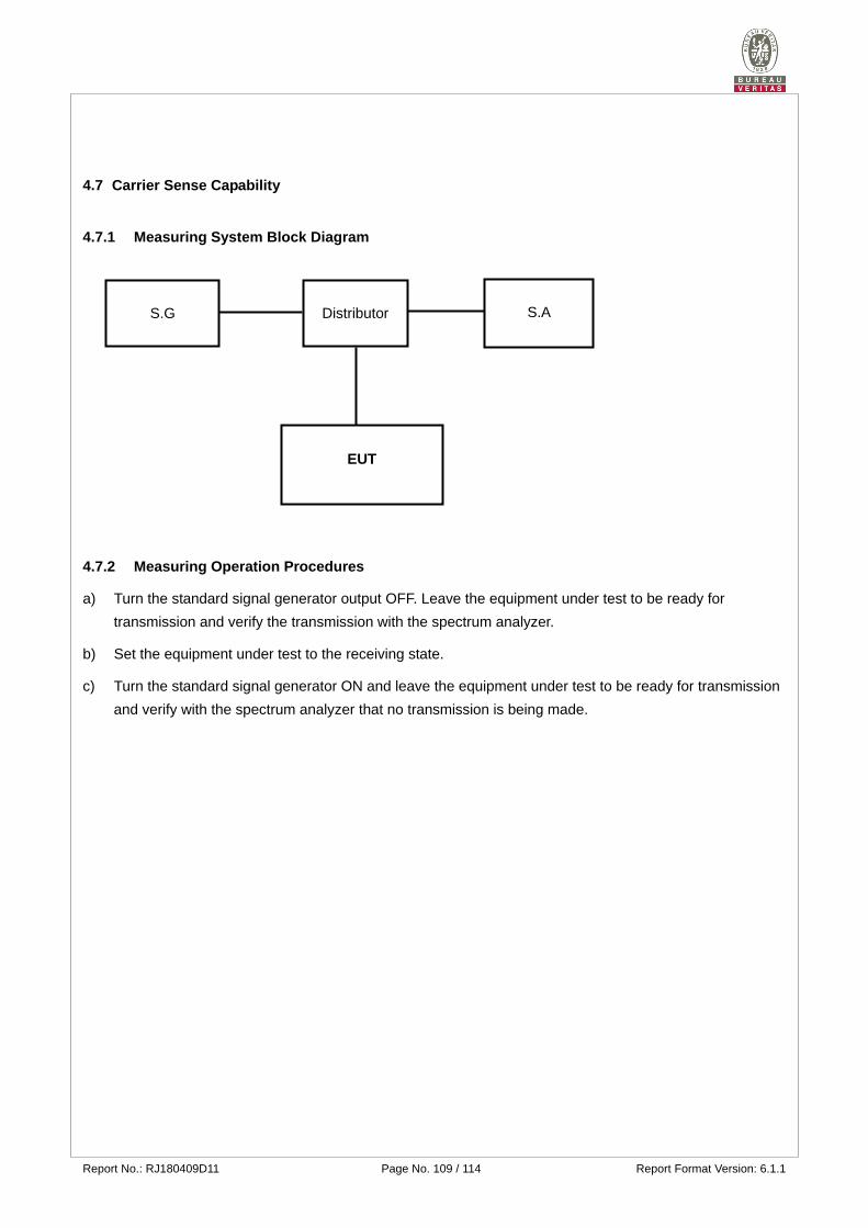
4.7.1 Measuring System Block Diagram
4.7.2 Measuring Operation Procedures
a) Turn the standard signal generator output OFF. Leave the equipment under test to be ready for
transmission and verify the transmission with the spectrum analyzer.
b) Set the equipment under test to the receiving state.
c) Turn the standard signal generator ON and leave the equipment under test to be ready for transmission
and verify with the spectrum analyzer that no transmission is being made.
S.G
Distributor
S.A
EUT
Report No.: RJ180409D11 Page No. 110 / 114 Report Format Version: 6.1.1
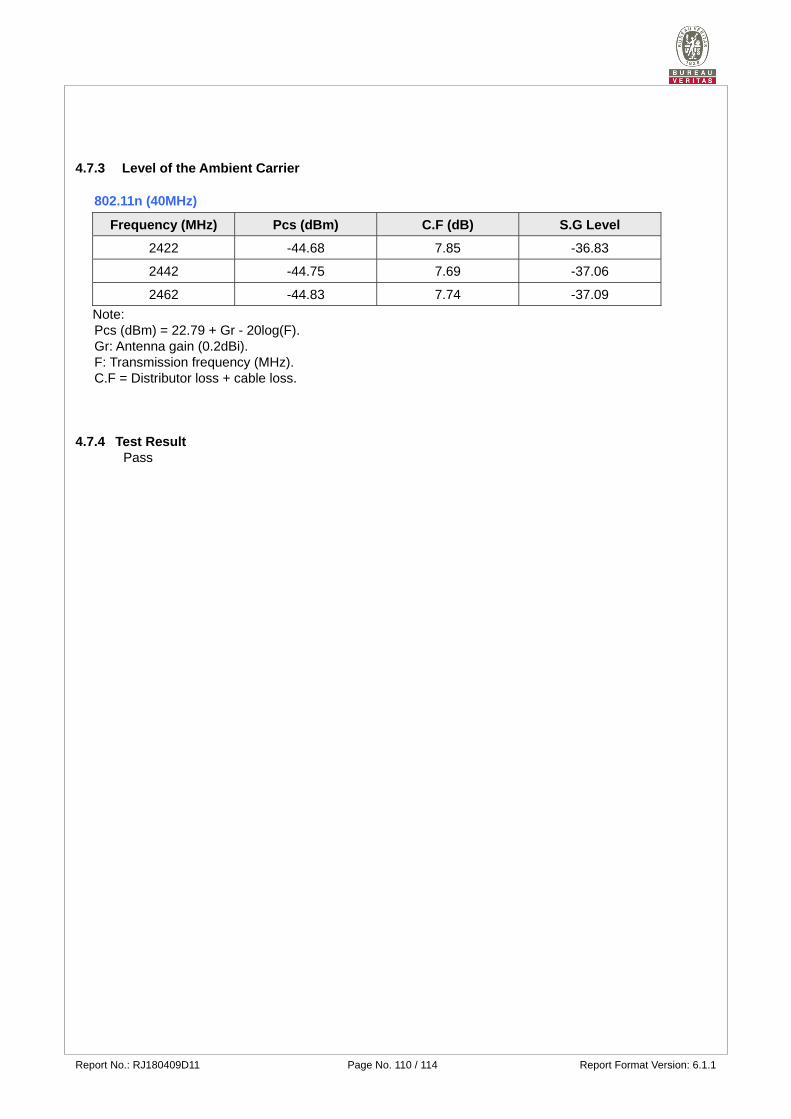
4.7.3 Level of the Ambient Carrier
802.11n (40MHz)
Frequency (MHz) Pcs (dBm) C.F (dB) S.G Level
2422 -44.68 7.85 -36.83
2442 -44.75 7.69 -37.06
2462 -44.83 7.74 -37.09 Note: Pcs (dBm) = 22.79 + Gr - 20log(F). Gr: Antenna gain (0.2dBi). F: Transmission frequency (MHz). C.F = Distributor loss + cable loss.
4.7.4 Test Result Pass
Report No.: RJ180409D11 Page No. 111 / 114 Report Format Version: 6.1.1
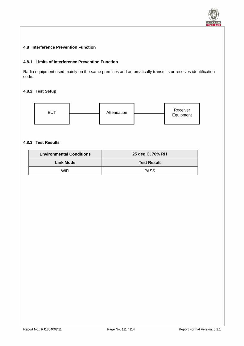
4.8 Interference Prevention Function
4.8.1 Limits of Interference Prevention Function
Radio equipment used mainly on the same premises and automatically transmits or receives identification code.
4.8.2 Test Setup
4.8.3 Test Results
Environmental Conditions 25 deg.C, 76% RH
Link Mode Test Result
WiFi PASS
EUT Attenuation Receiver
Equipment
Report No.: RJ180409D11 Page No. 112 / 114 Report Format Version: 6.1.1
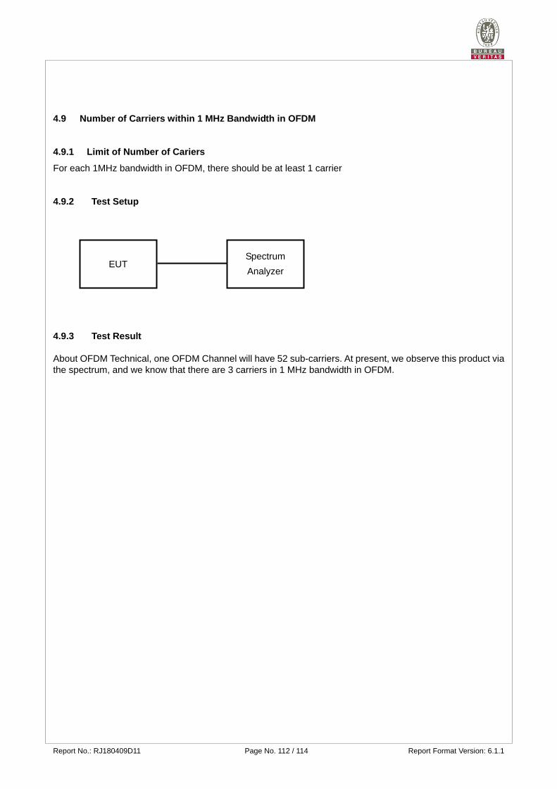
4.9 Number of Carriers within 1 MHz Bandwidth in OFDM
4.9.1 Limit of Number of Cariers
For each 1MHz bandwidth in OFDM, there should be at least 1 carrier
4.9.2 Test Setup
4.9.3 Test Result About OFDM Technical, one OFDM Channel will have 52 sub-carriers. At present, we observe this product via the spectrum, and we know that there are 3 carriers in 1 MHz bandwidth in OFDM.
EUT Spectrum
Analyzer
Report No.: RJ180409D11 Page No. 113 / 114 Report Format Version: 6.1.1
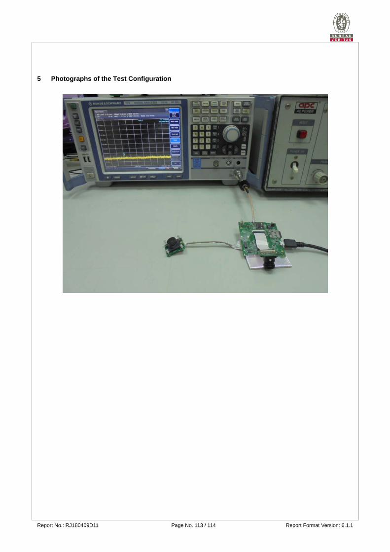
5 Photographs of the Test Configuration
Report No.: RJ180409D11 Page No. 114 / 114 Report Format Version: 6.1.1
Appendix - Information on the Testing Laboratories
We, Bureau Veritas Consumer Products Services (H.K.) Ltd., Taoyuan Branch, were founded in 1988 to provide our best service in EMC, Radio, Telecom and Safety consultation. Our laboratories are accredited and approved according to ISO/IEC 17025. If you have any comments, please feel free to contact us at the following:
Linko EMC/RF Lab
Tel: 886-2-26052180
Fax: 886-2-26051924
Hsin Chu EMC/RF/Telecom Lab
Tel: 886-3-6668565
Fax: 886-3-6668323
Hwa Ya EMC/RF/Safety Lab
Tel: 886-3-3183232
Fax: 886-3-3270892
Email: [email protected]
Web Site: www.bureauveritas-adt.com
The address and road map of all our labs can be found in our web site also. --- END ---
Related Documents