TM 11–5820-1102-30 TECHNICAL MANUAL DIRECT SUPPORT MAINTENANCE MANUAL RADIO SET, AN/PRC-132 (NSN 5820-01-320-8831) (EIC: CONSISTING OF N/A) RECEIVER-TRANSMITTER, RADIO RT-1648/PRC-132 (NSN 5820-01-320-3686) (EIC: N/A) AND BATTERY BOX CY-8629/PRC132 (NSN 6160-01-322-9366) (EIC: N/A) This publication is required for official use or for administrative or operational purposes only. Distribution is limited to US Government agencies. Other requests for this document must be referred to Commander, US Army Communications-Electronics Command and Fort Monmouth, ATTN: AMSEL- LC-LM-LT, Fort Monmouth, New Jersey 07703-5007. DESTRUCTION NOTICE - Destroy by any method that will prevent disclosure of contents or reconstruction of the document. HEADQUARTERS, DEPARTMENT OF THE ARMY 15 MAY 1992

Welcome message from author
This document is posted to help you gain knowledge. Please leave a comment to let me know what you think about it! Share it to your friends and learn new things together.
Transcript

TM 11–5820-1102-30
TECHNICAL MANUAL
DIRECT SUPPORTMAINTENANCE MANUAL
RADIO SET, AN/PRC-132(NSN 5820-01-320-8831) (EIC:
CONSISTING OFN/A)
RECEIVER-TRANSMITTER, RADIORT-1648/PRC-132
(NSN 5820-01-320-3686) (EIC: N/A)AND
BATTERY BOXCY-8629/PRC132
(NSN 6160-01-322-9366) (EIC: N/A)
This publication is required for official use or for administrative or operationalpurposes only. Distribution is limited to US Government agencies. Otherrequests for this document must be referred to Commander, US ArmyCommunications-Electronics Command and Fort Monmouth, ATTN: AMSEL-LC-LM-LT, Fort Monmouth, New Jersey 07703-5007.
DESTRUCTION NOTICE - Destroy by any method that will prevent disclosureof contents or reconstruction of the document.
HEADQUARTERS, DEPARTMENT OF THE ARMY15 MAY 1992


TM 11-5820-1102-30
SAFETY STEPS TO FOLLOW IF SOMEONE IS THEVICTIM OF ELECTRICAL SHOCK
DO NOT TRY TO PULL OR GRAB THE INDIVIDUAL
IF POSSIBLE, TURN OFF THE ELECTRICAL POWER
IF YOU CANNOT TURN OFF THE ELECTRICALPOWER, PULL, PUSH, OR LIFT THE PER SON TOSAFETY USING A DRY WOODEN POLE OR A DRYROPE OR SOME OTHER INSULATING MATERIAL
SEND FOR HELP AS SOON AS POSSIBLE
AFTER THE INJURED PERSON IS FREE OFCONTACT WITH THE SOURCE OF ELECTRICALSHOCK, MOVE THE PERSON A SHORT DISTANCEAWAY AND IMMEDIATELY START ARTIFICIALRESUSCITATION
a.
TM 11-5820-1102-30
INJURY
Excerpts from the US.
WARNING
CAN OCCUR IF THE FOLLOWING ARE NOT OBSERVEDWHEN USING OR REPAIRING THE RADIO SET
WARNING
RF RADIATION HAZARD
Government’s Federal OSHA Standard 1910.97 of Title 29 of the Code ofFederal Regulations for RF Hazards is provided as a guide in setting safety standards for operator andmaintenance personnel.
WARNINGFor normal environmental conditions, and for incident electromagnetic energy of frequencies
2from 10 MHz to 100 GHz, the radiation protection guide is 10 mW/cm (mW per squarecentimeter) as averaged over any 0.1 hour period. This means the following:
POWER DENSITY: Do not exceed 10 mW/cm2 for periods of 0.1 hour or more.
ENERGY DENSITY: Do not exceed 1 mW-Hr/cm2 (mW hour per square centimeter) duringany 0.1 hour period.
This standard applies whether radiation is continuous or intermittent.
WARNING
RF VOLTAGE WARNING
Exposed metal transceiver parts can assume an RF potential to ground when antenna is tuned withoutgrounding transceiver. To avoid potential RF burns, tie transceiver GND stud to ground.
Transmitbatteriescharge.
WARNING
TRANSMIT POWER LIMITATION
power is limited to a maximum of 20 watts when operating with two BA-5590 batteries. Whenare combined, transmit power may be limited dependent upon the relative state of the battery
WARNING
DO NOT SERVICE OR ADJUST ALONE
Do not attempt internal service or adjustment unless another person capable of rendering first aid andresuscitation is present.
b.
TM 11-5820-1102-30
WARNING
REMOVE ALL WATCHES, RINGS, NECKLACES, OR OTHER METAL ADORNMENTS FROM BODY
Dangerous voltages are present in the equipment and CAN RESULT IN SEVERE BURNS, INJURY, orEVEN DEATH if they come in contact with jewelry.
WARNING
GROUND THE SYSTEM
To minimize shock hazard, the equipment chassis must be connected to an electrical ground.
KEEP
The antenna is a source of electricalWHEN THE RADIO SET IS IN USE.antenna system.
WARNING
AWAY FROM LIVE CIRCUITS
and radio frequency energy. NEVER TOUCH THE ANTENNAAn RF burn may occur as a result of contact with an active
WARNING
ACCIDENTAL CONTACT WITH DC LINE VOLTAGE
Use caution when performing equipment maintenance. Accidentalcause injury.
contact with DC line voltage can
DO NOT REMOVE OR REINSERT MODULES OR PCBsWITHOUT REMOVING PRIMARY POWER FROM EQUIPMENT
To prevent the possibility of damaging equipment during maintenance, always remove primary powerfrom the transceiver when removing or reinserting modules, PCBs, or other plug-in assemblies.
CAUTION. CONTAINS PARTS AND ASSEMBLIES SUSCEPTIBLE TO DAMAGE BYELECTROSTATIC DISCHARGE (ESD).
C.
TM 11-5820-1102-30
WARNING
DO NOT SUBSTITUTE PARTS OR MODIFY SYSTEM
Do not install substitute parts or modify equipment in any manner.
WARNING
BERYLLIUM OXIDE WARNING
Beryllium oxide may be used as an electrical insulator/thermal conductor in some electroniccomponents contained within this equipment. Beryllium oxide easily goes to powder when crushed,and in this form is a toxic health hazard. Avoid crushing components which may contain berylliumoxide. In the event that suspected beryllium oxide powder is inhaled or swallowed, obtain medicalassistance immediately.
Dispose of items containing beryllium oxide in accordance with standard army procedure for berylliumoxide materials.
On Power Amplifier A13, transistors Q1, Q2, Q3, and Q4 contain beryllium oxide.
Circuit card A13 contains BERYLLIUM OXIDE (BeO) CERAMICS. The dust or fumes from BERYLLIUMOXIDE CERAMICS are HIGHLY TOXIC and breathing them can result in serious personal injury orDEATH. For local guidance/assistance on disposal of unserviceable circuit card A13, contact yourservicing Defense Reutilization and Marketing Office (DRMO).
WARNING
Al PROCESSOR BOARD WARNING
Processor board A1 contains a lithium battery. The lithium battery contains flammable organicmateriels. Incorrect handling may cause explosion. DO NOT short battery leads together, expose toextreme heat for more than 5-10 seconds, immerse in water or any cleaning solution, make a mistakein polarity, drop, or strike the battery.
d.

TM 11-5820-1102-30
A Iithium-sulfur dioxide (LiSO2) battery used with the AN/PRC-132 contains pressurized sulfur dioxide(SO2) gas. The gas is toxic, and the battery MUST NOT be abused in any way which may cause thebattery to rupture.
DO NOT heat, short circuit, crush, puncture, mutilate, or disassemble batteries.
DO NOT USE any battery which shows signs of damage, such as bulging, swelling, disfigurement, abrown liquid in the plastic wrap, a swollen plastic wrap, etc.
DO NOT test Li-SO2 batteries for capacity.
DO NOT recharge Li-SO2 batteries.
DO NOT dispose of lithium batteries with ordinary trash/refuse. Turn in batteries to your local servicingDefense Reutilization and Marketing Office.
WARNING
If the battery compartment becomes hot to the touch, if you hear a hissing sound (i.e., battery venting),or smell irritating sulfur dioxide gas, IMMEDIATELY Turn Off the equipment and leave the area.
1. Allow the equipment to cool at least one hour.
2. Remove and replace battery after the equipment has cooled to the touch.
3. If there is a safety incident, or if you believe a safety hazard exists, notify your localSafety Office/Officer, file a Quality Deficiency Report, SF Form 368, and notify theCECOM Safety Office, Ft. Monmouth, NJ at AV 995-3112.
WARNING
DO NOT use a HaIon type fire extinguisher on a lithium battery fire.
In the event of a fire, near a lithium battery(ies), rapid cooling of the lithium battery(ies) is important.Flood the equipment with water or use a carbon dioxide (CO2) extinguisher, Control of the equipmentfire, and cooling, may prevent the battery from venting and potentially exposing lithium metal. In theevent that lithium metal becomes involved in fire, the use of a graphite based Class D fire extinguisheris recommended, such as Lith-X or Met-L-X.
WARNING
DO NOT store batteries in unused equipment for more than 30 days.
DO NOT store lithium batteries with other hazardous materiels and keep them away from open flameor heat.
e/(f blank)


TM 11-5820-1102-30
Technical Manual
No. 11–5820–1102–30
HEADQUARTERSDEPARTMENT OF THE ARMYWashington, DC, 15 May 1992
DIRECT SUPPORTMAINTENANCE MANUAL
RADIO SET, AN/PRC-132(NSN 5820-01-320-8831) (EIC: N/A)
CONSISTING OF
RECEIVER-TRANSMITTER, RADIORT–1648/PRC-132
(NSN 5820-01-320-3686) (EIC: N/A)AND
BATTERY BOXCY-8629/PRC-132
(NSN 6160-01-322-9366) (EIC: N/A)
REPORTING ERRORS AND RECOMMENDING IMPROVEMENTSYou can help improve this manual. If you find any mistakes, or if you know of a way to improve the procedures,please let us know. Mail your letter, DA Form 2028 (Recommended Changes to Publications and BlankForms) or DA Form 2028–2 located in back of this manual direct to: Commander, US Army Communications–Electronics Command and Fort Monmouth, ATTN: AMSEL–LC–LM–LT, Fort Monmouth, New Jersey07703–5007.
In either case a reply will be furnished direct to you.
i

TM 11-5820-1102-30
TABLE OF CONTENTS
PAGE
CHAPTER 1 INTRODUCTION . . . . . . . . . . . . . . . . . . . . . . . . . . . . . . . . . . . . . . . . . . . . . . . . .
Section l. GENERAL INFORMATION . . . . . . . . . . . . . . . . . . . . . . . . . . . . . . . . . . . . . . . . . . . . . .1-1 SCOPE . . . . . . . . . . . . . . . . . . . . . . . . . . . . . . . . . . . . . . . . . . . . . . . . . . . . . . . . . . . . . . .1-1.1 Type of Manual . . . . . . . . . . . . . . . . . . . . . . . . . . . . . . . . . . . . . . . . . . . . . . . . . . . . . . . .1-1.2 Model Number and Equipment Name . . . . . . . . . . . . . . . . . . . . . . . . . . . . . . . . . . . . . . . . .1-1.3 Purpose of Equipment . . . . . . . . . . . . . . . . . . . . . . . . . . . . . . . . . . . . . . . . . . . . . . . . . . .1-2 MAINTENANCE FORMS, RECORDS, AND REPORTS . . . . . . . . . . . . . . . . . . . . . . . . . . . . . . . .1-2.1 Reports Of Maintenance and Unsatisfactory Equipment . . . . . . . . . . . . . . . . . . . . . . . . . . . . ,1-2.2 Report of Packaging and Handling Deficiencies . . . . . . . . . . . . . . . . . . . . . . . . . . . . . . . . . .1-2.3 Transportation Discrepancy Report (TDR) (SF361) . . . . . . . . . . . . . . . . . . . . . . . . . . . . . . . .1-3 DESTRUCTION OF ARMY MATERIEL TO PREVENT ENEMY USE . . . . . . . . . . . . . . . . . . . . . . .1-4 NOMENCLATURE CROSS REFERENCE LIST . . . . . . . . . . . . . . . . . . . . . . . . . . . . . . . . . . . . .1-5 REPORTING EQUIPMENT IMPROVEMENT RECOMMENDATIONS (EIR) . . . . . . . . . . . . . . . . . . .
Section ll. EQUIPMENT DESCRIPTION AND DATA . . . . . . . . . . . . . . . . . . . . . . . . . . . . . . . . . . . .1-6 EQUIPMENT CHARACTERISTICS, CAPABILITIES, AND FEATURES . . . . . . . . . . . . . . . . . . . . . .1-7 LOCATION AND DESCRIPTION OF MAJOR COMPONENTS . . . . . . . . . . . . . . . . . . . . . . . . . . .1-7a Processor A1 . . . . . . . . . . . . . . . . . . . . . . . . . . . . . . . . . . . . . . . . . . . . . . . . . . . . . . . . . .1-7b 1st LO A2 . . . . . . . . . . . . . . . . . . . . . . . . . . . . . . . . . . . . . . . . . . . . . . . . . . . . . . . . . . .1-7c 2nd LO A3 . . . . . . . . . . . . . . . . . . . . . . . . . . . . . . . . . . . . . . . . . . . . . . . . . . . . . . . . . . .1-7d Product Detector A7 . . . . . . . . . . . . . . . . . . . . . . . . . . . . . . . . . . . . . . . . . . . . . . . . . . . . .1-7e 2nd lF A8 . . . . . . . . . . . . . . . . . . . . . . . . . . . . . . . . . . . . . . . . . . . . . . . . . . . . . . . . . . . .1-7f 1st lF A9 . . . . . . . . . . . . . . . . . . . . . . . . . . . . . . . . . . . . . . . . . . . . . . . . . . . . . . . . . . . . .1-7g 1st Mixer A10 . . . . . . . . . . . . . . . . . . . . . . . . . . . . . . . . . . . . . . . . . . . . . . . . . . . . . . . . .1-7h 1st Filter A11 . . . . . . . . . . . . . . . . . . . . . . . . . . . . . . . . . . . . . . . . . . . . . . . . . . . . . . . . . .1-7i 2nd Filter A12 ......... . . . . . . . . . . . . . . . . . . . . . . . . . . . . . . . . . . . . . . . . . . . . . . . .1-7j Power Amplifier A13 . . . . . . . . . . . . . . . . . . . . . . . . . . . . . . . . . . . . . . . . . . . . . . . . . . . . .1-7k lnterconnect Board A14. . . . . . . . . . . . . . . . . . . . . . . . . . . . . . . . . . . . . . . . . . . . . . . . . . .1-7l Display Board A15 . . . . . . . . . . . . . . . . . . . . . . . . . . . . . . . . . . . . . . . . . . . . . . . . . . . . . . .1-7m Front Panel Board A16.. . . . . . . . . . . . . . . . . . . . . . . . . . . . . . . . . . . . . . . . . . . . . . . . . .1-7n Control Panel Assembly A22 . . . . . . . . . . . . . . . . . . . . . . . . . . . . . . . . . . . . . . . . . . . . . . .1-7o Spare Card Slots.... . . . . . . . . . . . . . . . . . . . . . . . . . . . . . . . . . . . . . . . . . . . . . . . . . .1-8 EQUIPMENT DATA . . . . . . . . . . . . . . . . . . . . . . . . . . . . . . . . . . . . . . . . . . . . . . . . . . . . . . .1-9 SAFE, CARE, AND HANDLING . . . . . . . . . . . . . . . . . . . . . . . . . . . . . . . . . . . . . . . . . . . . .
Section III. PRINCIPLES OF OPERATION . . . . . . . . . . . . . . . . . . . . . . . . . . . . . . . . . . . . . . . . . . .1-10 GENERAL DESCRIPTION . . . . . . . . . . . . . . . . . . . . . . . . . . . . . . . . . . . . . . . . . . . . . . . . .1-11 RECEIVE PATH CIRCUITRY. . . . . . . . . . . . . . . . . . . . . . . . . . . . . . . . . . . . . . . . . . . . . . . .1-11.1 Receive Frequency Conversion . . . . . . . . . . . . . . . . . . . . . . . . . . . . . . . . . . . . . . . . . . . .1-11.2 Receiver Sensitivity . . . . . . . . . . . . . . . . . . . . . . . . . . . . . . . . . . . . . . . . . . . . . . . . . . . .1-11.3 Receiver Selectivity . . . . . . . . . . . . . . . . . . . . . . . . . . . . . . . . . . . . . . . . . . . . . . . . . . . .1-11.4 IF Rejection . . . . . . . . . . . . . . . . . . . . . . . . . . . . . . . . . . . . . . . . . . . . . . . . . . . . . . . . . .1-11.5 Image Rejection . . . . . . . . . . . . . . . . . . . . . . . . . . . . . . . . . . . . . . . . . . . . . . . . . . . . . .1-11.6 Audio Distortion . . . . . . . . . . . . . . . . . . . . . . . . . . . . . . . . . . . . . . . . . . . . . . . . . . . . . . .1-12 TRANSMIT PATH CIRCUITRY . . . . . . . . . . . . . . . . . . . . . . . . . . . . . . . . . . . . . . . . . . . . . . .1-12.1 Transmit Frequency Conversion . . . . . . . . . . . . . . . . . . . . . . . . . . . . . . . . . . . . . . . . . .1-12.2 RF Output Power.... . . . . . . . . . . . . . . . . . . . . . . . . . . . . . . . . . . . . . . . . . . . . . . . . .1-12.3 Intermodulation Distortion . . . . . . . . . . . . . . . . . . . . . . . . . . . . . . . . . . . . . . . . . . . . . . .1-12.4 Carrier Suppression. . . . . . . . . . . . . . . . . . . . . . . . . . . . . . . . . . .. . . . . . . . . . . .1-12.5 Opposite Sideband Suppression . . . . . . . . . . . . . . . . . . . . . . . . . . . . . . . . . . . . . . . . . . .
ii
1-1
1-11-11-11-11-11-11-11-11-11-11-11-2
1-21-21-21-31-31-31-31-31-31-31-31-31-31-31-31-31-51-51-51-5
1-61-61-61-71-101-101-111-111-121-121-141-161-161-161-16

PAGE
TM 11-5820-1102-30
TABLE OF CONTENTS (con’t)
1-12.60 Output Load impedance. . . . . . . . . . . . . . . . . . . . . . . . . . . . . . . . . . . . . . . . . . . . . . . . . 1-161-12.7 Voltage Standing Wave Ratio (VSWR) . . . . . . . . . . . . . . . . . . . . . . . . . . . . . . . . . . . . . ...1-171-13 SYNTHESIZER CIRCUITRY. . . . . . . . . . . . . . . . . . . . . . . . . . . . . . . . . . . . . . . . . . . . . . . . . 1-171-13.1 Frequency Range.. . . . . . . . . . . . . . . . . . . . . . . . . . . . . . . . . . . . . . . . . . . . . . . . . ...1-191-13.2 Frequency Accuracy.. . . . . . . . . . . . . . . . . . . . . . . . . . . . . . . . . . . . . . . . . . . . . . . . ...1-191-14 POWER SUPPLY AND DISTRIBUTION CIRCUITRY . . . . . . . . . . . . . . . . . . . . . . . . . . . . . . ...1-191-14.1 Reverse Voltage Protection . . . . . . . . . . . . . . . . . . . . . . . . . . . . . . . . . . . . . . . . . . . . ...1-191-14.2 Power Drain . . . . . . . . . . . . . . . . . . . . . . . . . . . . . . . . . . . . . . . . . . . . . . . . . . . . . . ...1-191-15 CONTROL AND INTERFACE CIRCUITRY . . . . . . . . . . . . . . . . . . . . . . . . . . . . . . . . . . . . . ..1-201-15.1 Secure Lighting . . . . . . . . . . . . . . . . . . . . . . . . . . . . . . . . . . . . . . . . . . . . . . . . . . . . ...1-201-15.2 Electrical Interface.. . . . . . . . . . . . . . . . . . . . . . . . . . . . . . . . . . . . . . . . . . . . . . . . . ...1-20
CHAPTER 2 DIRECT SUPPORT MAINTENANCE . . . . . . . . . . . . . . . . . . . . . . . . . . . . . . . . . . . . 2-1
Section l. REPAIR PARTS AND SPECIAL TOOLS . . . . . . . . . . . . . . . . . . . . . . . . . . . . . . . . . . ...2-12-1 COMMON TOOLS, SPECIAL TOOLS, TMDE, AND SUPPORT EQUIPMENT . . . . . . . . . . . . . . . . . 2-1
Section ll. MAINTENANCE PROCEDURES . . . . . . . . . . . . . . . . . . . . . . . . . . . . . . . . . . . . . . . ...2-12-2 ASSEMBLY AND DISASSEMBLY . . . . . . . . . . . . . . . . . . . . . . . . . . . . . . . . . . . . . . . . . . . . . . 2-12-2.1 Card Cage Removal and Assembly . . . . . . . . . . . . . . . . . . . . . . . . . . . . . . . . . . . . . . . ...2-22-2.1.1 Disassembly . . . . . . . . . . . . . . . . . . . . . . . . . . . . . . . . . . . . . . . . . . . . . . . . . . . . . . ...2-22-2.1.2 Assembly . . . . . . . . . . . . . . . . . . . . . . . . . . . . . . . . . . . . . . . . . . . . . . . . . . . . . . . . ...2-22-2.2 Removal and Assembly of interconnect Board A14 . . . . . . . . . . . . . . . . . . . . . . . . . . . . . ...2-22-2.2.1 Disassembly . . . . . . . . . . . . . . . . . . . . . . . . . . . . . . . . . . . . . . . . . . . . . . . . . . . . . . ...2-22-2.2.1 Assembly . . . . . . . . . . . . . . . . . . . . . . . . . . . . . . . . . . . . . . . . . . . . . . . . . . . . . . . . ...2-22-2.3 Removal and Assembly of Control Panel A22 . . . . . . . . . . . . . . . . . . . . . . . . . . . . . . . . ...2-22-2.3.1 Disassembly . . . . . . . . . . . . . . . . . . . . . . . . . . . . . . . . . . . . . . . . . . . . . . . . . . . . . . . ..2-22-2.3.2 Assembly . . . . . . . . . . . . . . . . . . . . . . . . . . . . . . . . . . . . . . . . . . . . . . . . . . . . . . . . ...2-22-2.4 Removal and Assembly of Front Panel Bezel . . . . . . . . . . . . . . . . . . . . . . . . . . . . . . . . . ...2-62-2.4.1 Disassembly . . . . . . . . . . . . . . . . . . . . . . . . . . . . . . . . . . . . . . . . . . . . . . . . . . . . . . . ..2-62-2.4.2 Assembly . . . . . . . . . . . . . . . . . . . . . . . . . . . . . . . . . . . . . . . . . . . . . . . . . . . . . . . . . . . 2-62-2.5 Removal and Assembly of Power Amplifier A13 . . . . . . . . . . . . . . . . . . . . . . . . . . . . . . . ...2-62-2.5.1 Disassembly . . . . . . . . . . . . . . . . . . . . . . . . . . . . . . . . . . . . . . . . . . . . . . . . . . . . . . . ..2-62-2.5.2 Assembly . . . . . . . . . . . . . . . . . . . . . . . . . . . . . . . . . . . . . . . . . . . . . . . . . . . . . . . . ...2-62-2.6 Disassembly and Assembly of Battery Box to Allow Access to Q1, CR1, and CR2 . . . . . . . . . . 2-62-2.6.1 Disassembly . . . . . . . . . . . . . . . . . . . . . . . . . . . . . . . . . . . . . . . . . . . . . . . . . . . . . . ...2-82-2.6.2 Assembly . . . . . . . . . . . . . . . . . . . . . . . . . . . . . . . . . . . . . . . . . . . . . . . . . . . . . . . . . ..2-82-3 Repair . . . . . . . . . . . . . . . . . . . . . . . . . . . . . . . . . . . . . . . . . . . . . . . . . . . . . . . . . . . . . ...2-6
CHAPTER 3 TROUBLESHOOTING . . . . . . . . . . . . . . . . . . . . . . . . . . . . . . . . . . . . . . . . . . . ...3-1
Section l. GENERAL OPERATION TESTS . . . . . . . . . . . . . . . . . . . . . . . . . . . . . . . . . . . . . . . ...3-13-1 TEST CONDITIONS . . . . . . . . . . . . . . . . . . . . . . . . . . . . . . . . . . . . . . . . . . . . . . . . . . . . ..3-13-2 POWER ON TEST . . . . . . . . . . . . . . . . . . . . . . . . . . . . . . . . . . . . . . . . . . . . . . . . . . . . . . . 3-13-3 FREQUENCY PROGRAMMING AND SECURE LIGHTING TEST . . . . . . . . . . . . . . . . . . . . . . . . . 3-23-3.1 Load Frequencies for Channels 1 - 11 . . . . . . . . . . . . . . . . . . . . . . . . . . . . . . . . . . . . . . . .3-23-3.1.1 Setting Channels . . . . . . . . . . . . . . . . . . . . . . . . . . . . . . . . . . . . . . . . . . . . . . . . . . ...3-23-3.2 Frequency and Channel Scan . . . . . . . . . . . . . . . . . . . . . . . . . . . . . . . . . . . . . . . . . . . . . . 3-4
iii
TM 11-5820-1102-30
TABLE OF CONTENTS (con’t)
PAGE
3-3.2.1 Scanning Frequencies.. . . . . . . . . . . . . . . . . . . . . . . . . . . . . . . . . . . . . . . . . . . . . . 3-43-3.2.2 Scanning Channels.. . . . . . . . . . . . . . . . . . . . . . . . . . . . . . . . . . . . . . . . . . . . . . . . ...343-3.3 Secure Lighting . . . . . . . . . . . . . . . . . . . . . . . . . . . . . . . . . . . . . . . . . . . . . . . . . . . . . ...3-53-4 RECEIVER TESTS . . . . . . . . . . . . . . . . . . . . . . . . . . . . . . . . . . . . . . . . . . . . . . . . . . . . . . . 3-63-4.1 No RX . . . . . . . . . . . . . . . . . . . . . . . . . . . . . . . . . . . . . . . . . . . . . . . . . . . . . . . . . . . . . . 3-63-4.2 Low Audio . . . . . . . . . . . . . . . . . . . . . . . . . . . . . . . . . . . . . . . . . . . . . . . . . . . . . . . . . ..3-63-4.3 Sensitivity Test . . . . . . . . . . . . . . . . . . . . . . . . . . . . . . . . . . . . . . . . . . . . . . . . . . . . . . . . 3-63-4.4 Audio Distortion Test.. . . . . . . . . . . . . . . . . . . . . . . . . . . . . . . . . . . . . . . . . . . . . . . . ...3-83-5 TRANSMIT TESTS . . . . . . . . . . . . . . . . . . . . . . . . . . . . . . . . . . . . . . . . . . . . . . . . . . . . ...3--83-5.1 Transmit Power Out Test . . . . . . . . . . . . . . . . . . . . . . . . . . . . . . . . . . . . . . . . . . . . . ...3-93-5.2 Frequency Accuracy Test . . . . . . . . . . . . . . . . . . . . . . . . . . . . . . . . . . . . . . . . . . . . . . ...3-113-5.3 Automatic Leveling Control (ALC) Test . . . . . . . . . . . . . . . . . . . . . . . . . . . . . . . . . . . . . ..3-11
Section ll. TROUBLESHOOTING PROCEDURE . . . . . . . . . . . . . . . . . . . . . . . . . . . . . . . . . . . . ...3-153-6 TROUBLESHOOTING . . . . . . . . . . . . . . . . . . . . . . . . . . . . . . . . . . . . . . . . . . . . . . . . . . . ...3-15
APPENDIX A - REFERENCES . . . . . . . . . . . . . . . . . . . . . . . . . . . . . . . . . . . . . . . . . . . . . . . . . A-1
APPENDIX B - EXPENDABLE SUPPLIES AND MATERIELS LIST . . . . . . . . . . . . . . . . . . . . . . . . ..B-1
GLOSSARY . . . . . . . . . . . . . . . . . . . . . . . . . . . . . . . . . . . . . . . . . . . . . . . . . .. . . . . . . . . . . ..G-1
ALPHABETlCAL INDEX . . . . . . . . . . . . . . . . . . . . . . . . . . . . . . . . . . . . . . . . . . . . . . . . . . . . ...I-1
iv

TM 11-5820-1102-30
LIST OF ILLUSTRATIONS
PAGE
Radio Set- AN/PRC-132 . . . . . . . . . . . . . . . . . . . . . . . . . . . . . . . . . . . . . . . . . . . . . . . 1-0
FIGURE 1-1. Transceiver, RT-1648 internal components . . . . . . . . . . . . . . . . . . . . . . . . . . . . . . 1-4FIGURE 1-2. Transceiver, RT-1648 receive path block diagram . . . . . . . . . . . . . . . . . . . . . . . . . . . . 1-8FIGURE 1-3. Transceiver, RT-1648 transmit path block diagram . . . . . . . . . . . . . . . . . . . . . . . . . . . 1-15FIGURE 1-4. Transceiver synthesizer . . . . . . . . . . . . . . . . . . . . . . . . . . . . . . . . . . . . . . . . . ...1-18FIGURE 1-5. Block diagram, interface and control circuitry . . . . . . . . . . . . . . . . . . . . . . . . . . . . . . 1-21FIGURE FO-1. Transceiver, RT-1648 block diagram . . . . . . . . . . . . . . . . . . . . . . . . . . . . . . . . . ..FP 1FIGURE FO-2. Interconnect Board A14 to PCB interconnection diagram. . . . . . . . . . . . . . . . . . . . . .FP 3
FIGURE 2-1. Removing chassis from housing, gasket and o-ring location . . . . . . . . . . . . . . . . . . . . 2-3FIGURE 2-2. Location of Interconnect Board A14 hex and phillips retaining screws . . . . . . . . . . . . . . 2-4FlGURE 2-3. Front panel assembly removal . . . . . . . . . . . . . . . . . . . . . . . . . . . . . . . . . . . . . . ...2-5FIGURE 2-4. Removal of Power Amplifier A13 . . . . . . . . . . . . . . . . . . . . . . . . . . . . . . . . . . . . ...2-7FlGURE 2-5. Battery box disassembly . . . . . . . . . . . . . . . . . . . . . . . . . . . . . . . . . . . . . . . . . . ...2-9
FIGURE 3-1. Test equipment setup for receive and sensitivity tests . . . . . . . . . . . . . . . . . . . . . . . . 3-7FIGURE 3-2. Test equipment setup for transmit power out test . . . . . . . . . . . . . . . . . . . . . . . . . . . 3-12FIGURE 3-3. Test equipment setup for frequency accuracy test . . . . . . . . . . . . . . . . . . . . . . . . . . 3-13FIGURE 3-4. Test equipment setup for automatic leveling control test . . . . . . . . . . . . . . . . . . . . . . . 3-14FlGURE 3-5. Q1, graphic and electrical diagrams . . . . . . . . . . . . . . . . . . . . . . . . . . . . . . . . . . ...3-24
v

TM 11-5820-1102-30
Radio Set-AN/PRC-132
1-0

TM 11–5820-1102-30
CHAPTER 1
INTRODUCTION
Section I. GENERAL INFORMATION
INTRODUCTION 1-1
1-1. SCOPE.
1–1.1 Type of Manual Direct Support Maintenance Manual.
1–1.2 Model Number and Equipment Name AN/PRC–132 Radio Set.
1–1.3 Purpose of Equipment The AN/PRC–132 manpack High Frequency/Very High Frequency (HF/VHF)(AM only) radio set is designed to provide data, voice, and Continuous Wave (CW) communications to support Specialoperations Forces (SOF) communications requirements.
1–2. MAINTENANCE FORMS. RECORDS, AND REPORTS.
1–2.1 Reports of Maintenance and Unsatisfactory Equipment. Department of the Army forms and procedures usedor equipment maintenance will be those prescribed by DA Pam 738–750, as contained in Maintenance Management
Update.
1-2.2 Reporting of Item and Packaging Discrepancies. Fill out and forward SF 364 (Report of Discrepancy (ROD))as prescribed in AR 735–11–2/DLAR 4140.55/SECNAVINST 4355.18/AFR400–54/MCO4430.3J.
1 –1.3 Transportation Discrepancy Report (TDR) (SF 361). Fill out and forward Transportation Discrepancy Report(TDR) (SF 361) as prescribed in AR 55-38/NAVSUPINST 4610.33C/AFR 75-18/MCOP4610.19D/DLAR 4500.15.
1–3. DESTRUCTION OF ARMY ELECTRONICS MATERIEL.
Destruction of Army electronics materiel to prevent enemy use shall be in accordance with TM 750-244-2.
1-4. NOMENCLATURE CROSS–REFERENCE LIST.
Common Name Official Name
Radio Set Radio Set – AN/PRC–132
Transceiver Receiver-Transmitter, Radio–RT–1648/PRC-132
Battery Box Battery Box – CY-8629/PRC-132
1 - 1

TM 11–5820-1102-30
1–5. REPORTING EQUIPMENT IMPROVEMENT RECOMMENDATIONS (EIR).
If your radio set needs improvement, let us know. Send us an EIR. You, the user, are the only one who can tell us whatyou don’t like about your equipment. Let us know why you don’t like the design or performance. Put it on an SF 368(Product Quality Deficiency Report). Mail it to us at:
Commander,US Army Communications–Electronics Command
and Fort MonmouthATTN: AMSEL–ED-PHFort Monmouth, NJ 07703–5007.
We’ll send you a reply.
Section Il. EQUIPMENT DESCRIPTION AND DATA
1–6. EQUIPMENT CHARACTERISTICS. CAPABILITIES, AND FEATURES.
Refer to the AN/PRC–132 Radio Set Operator’s and Unit Maintenance manual (TM 11–5820–1102–12) for generalequipment characteristics, capabilities, and features.
The transceiver is of modular construction. Transceiver circuitry is housed within an aluminum case. Front panelcircuitry and nine Printed Circuit Boards (PCBs) plug into an interconnection board. Each PCB is held in place by acombination of mating connectors, card cage guides, fastener hardware, and the housing itself. A card cage assemblyuses card guides to support each PCB by the edges. card guides include beryllium copper spring contacts that provideadditional retaining force and positive ground contact for each PCB. Individually shielded cavities provide isolationbetween each PCB.
A power amplifier is installed into the housing.
The housing acts as a fail–safe retainer by preventing the PCBs from disengaging far enough to lose electrical contactwith mating connectors. The housing is designed with a bulkhead that separates the front cavity (where the card cageassembly is enclosed) from the rear cavity (where the power amplifier is enclosed). The housing conducts heat awayfrom the power amplifier.
The transceiver has limited Built–In–Test (BIT) capabilities. Fuses provide current overload protection for thetransceiver and for each PCB. The BIT function consists of a Light Emitting Diode (LED) located on the edge of eachPCB that lights to indicate a blown fuse and lose of DC power.
The battery box is of two–piece construction, and is capable of accepting one or two BB–590 batteries, two BA-5590batteries, or a combination of one BB–590 and one BA–5590.
Battery box half–sections fit together to form a watertight battery enclosure. The battery box housing interfaceswith the transceiver and contains a PCB, connectors, and a pressure relief valve. The battery box rear coverforms the rear of the battery box and provides access to batteries. Battery box repair is limited as specified in theMaintenance Allocation Chart (MAC).
1–7. LOCATION AND DESCRIPTION OF MAJOR COMPONENTS.
Refer to the AN/PRC–132 Radio Set Operator’s and Unit Maintenance manual (TM 11–5820–1102-12) for locationand description of major equipment components.
All replaceable units are electrically interchangeable. Refer to Figure 1–1 for internal component locations. Thetransceiver consists of the following replaceable units:
1 –2

TM 11-5820-1102-30
NOTE
Units marked with an asterisk (*) are not replaceable at the Direct Support level, anddescriptions are included for information only.
a. Processor A1. Processor A1 controls most transceiver functions. It accepts operator input via front panelcontrols, and stores channel and frequency data in memory. Processor A1 controls synthesizers, LCD, andfilter relays, It communicates with other units via a data bus.
b. 1st LO A2. 1st LO A2 provides a 73.80-122.19 MHz signal used in frequency conversion. It also providesa 5.12 MHz time base to product detector A7, to 2nd LO A3, and to processor A1. Output is +7 dBm,minimum.
c. 2nd LO A3. 2nd LOis +7 dBm, minimum.
d. Product Detector A7.provides audio output to
A3 provides a 82.4301 - 82.4400 MHz signal used in frequency conversion. Output
In receive mode, Product Detector A7 demodulates a filtered 10.24 MHz input andthe front panel AUDIO connectors. In transmit mode, Product Detector A7 accepts
audio input from the AUDIO connectors and generates a suppressed carrier double sideband signal at10.24 MHz,
e. 2nd IF A8. 2nd IF A8 provides sideband filtering at 10.24 MHz, and transmit amplification.
f. 1st IF A9. In receive mode, 1st IF A9 provides first and second frequency conversion of the input RF signal.Its output is 10.24 MHz. In transmit mode, 1st IF A9 provides frequency conversion of a 10.24 MHz input toa 72,1901 -72.2000 MHz output.
g. 1st Mixer A10, 1st Mixer A10 is used in transmit only. It provides frequency conversion, widebandamplification, and filtering. It also provides Automatic Level Control (ALC) gain control circuitry.
h. 1st Filter A11. 1st Filter A11 provides harmonic rejection filtering for frequencies from1.6000-11.4399 MHz.
i. 2nd Fitter A12. 2nd Filter A12 provides harmonic rejection filtering for frequencies from 11.4400 - 49.9999MHz. It also contains ALC detector circuitry.
j. Power Amplifier A13. Power Amplifier A13 provides transmit power amplification up to 50 watts. Connectionbetween the power amplifier (located on the transceiver housing) and the card cage is made through a floatingconnector mounted on the power amplifier assembly. The connector mates with the rear of the card cagewhen housing and card cage are assembled together. The transceiver rear housing plate contains a batterybox interconnection, This connector is wired to the power amplifier, through the floating connector, and to thecard cage. Refer to housing assembly in MAC for repair limitations.
k. Interconnect Board A14. Interconnect Board A14 provides interconnection between the plug-in circuitcards. Refer to chassis assembly in MAC for repair limitations.
l. Display Board A15.* Display Board A15 includes a Liquid Crystal Display (LCD) and its control circuitry.It also contains an EMI filter in the antenna path. Display Board A15 is a component of Control PanelAssembly A22.
m. Front Panel Board A16.* Front Panel Board A16 provides interface between front panel controls andProcessor A1. Front Panel Board A16 is a component of Control Panel Assembly A22.
1-3

TM 11-5820-1102-30
FIGURE 1-1. Transceiver, RT-1648 Internal components
1-4
TM 11-5820-1102-30
n. Control Panel Assembly A22. Control Panel Assembly A22 includes Display Board A15 and Front Panel
Board A16 as one replaceable unit for Direct Support maintenance. Viewing the transceiver from front panel
to rear, Control Panel Assembly A22 is the first replaceable unit viewed.
o. Spare Card Slots. J6, J8, and J12 are not used at the present time.
1-8 EQUIPMENT DATA.
Refer to the AN/PRC-132 Radio Set Operator’s and Unit Maintenance manual (TM 11-5820-1102-12) for generalequipment data.
1-9 SAFETY, CARE, AND HANDLING.
Refer to the AN/PRC-132 Radio Set Operator’s and Unit Maintenance manual (TM 11-5820-1102-12) for generalsafety, care, and handling requirements.
It is the technician’s responsibility to understand and apply the following safety precautions during all phasesof equipment operation, service, and repair. Failure to comply with these precautions, or with specific warningselsewhere in this manual violates safety standards of design, manufacture, and intended use.
Transceiver internal voltages exceeding 30 volts rms are those associated with transmitter RF power output.These voltages are present at Power Amplifier A13, 1st Filter A11, 2nd Filter A12, and at the coaxialinterconnection to the Electromagnetic Interference (EMI) filter and antenna connector located on Control PanelAssembly A22.
1st Filter A11, 2nd Filter A12, and the coaxial interconnection to the antenna connector are located in the cardcage assembly. Access to this circuitry can only be obtained by removing the card cage assembly from thehousing.
When the card cage assembly is removed from the housing, all power is automatically disconnected frominternal circuitry.
Removal of safety shields or use of extender card on 1st Fitter A11 and 2nd Fitter A12 willexpose voltages that may be dangerous. Use caution when working near exposed circuitry.
If external test cables are used to power the transceiver during maintenance, additional protection exists. 1stFitter A11 and 2nd Filter A12, when plugged into their respective jack slots, limit technician access to the backof the board. Likewise, the coaxial interconnection to the EMI filter and antenna connector is guarded byshielded enclosures covering Interconnect Board A14.
Power Amplifier A13 is located in the rear cavity of the housing. Access to this cavity requires removal of thetransceiver power source.
WARNING
Removal of safety shields will expose electrical currents that may be dangerous. Usecaution when working near exposed circuitry.
1-5

TM 11-5820-1102-30
The only high current source associated with the radio set is the battery power source. Normally, interconnecting cables to the battery power source are not exposed, except during equipment disassemblywhen the battery power source is disconnected from the transciever. When an external cable is used tointerconnect a high current source to the removed card cage, the interconnecting wire from the power sourceto the front panel power switch is covered by a shield that encloses interconnect Board A14.
Refer to general warnings in front of manual before performing equipment maintenance.
Section Ill. PRINCIPLES OF OPERATION
1-10 GENERAL DESCRIPTION.
Refer to the AN/PRC-132 Radio Set Operator’s and Unit Maintenance manual (TM 11-5820-1102-12) for adescription of general principles of operation.
Transceiver control circuitry is based upon microprocessor control of timing and switching signals for frequencysynthesis, filter switching, and transmit-receive (T/R) switching. The microprocessor is interrupt driven tominimize EMI from clock and data signals in receiver circuitry, and to reduce external spurious emissions. Thismeans that the microprocessor and its associated circuitry are inactive until the operator pushes any of thethree control buttons or the radio keyline push-to-talk (PTT), which causes an interrupt, At this time, controlcircuitry activates to perform the appropriate command, and then returns to the inactive state.
Front panel controls and radio keylines interface to an Erasable Programmable Logic Device (EPLD) locatedwithin transceiver circuitry. This device encodes the input commands into microprocessor logic signals andprovides activation calls for the microprocessor. The microprocessor, along with associated ErasableProgrammable Read Only Memory (EPROM) and Random Access Memory (RAM) circuitry, generates therequired transceiver commands and outputs them through control bus drivers to associated circuitry. RAMstores channels and frequencies programmed by the operator. The LCD shows frequency and channelinformation.
Figure FO-1 illustrates a transceiver signal path block diagram. Within the transceiver, electrical circuitry iscomposed of five distinct subsections: receive path circuitry, transmit path circuitry, synthesizer circuitry, powersupply and distribution circuitry, and control and interface circuitry.
Subsection placement puts interface and control circuitry near the transceiver front panel. Display Board Al 5and Front Panel Board Al 6 are mounted to Control Panel Assembly A22, which is attached to the card cageassembly with four screws.
Processor A1 occupies J3 nearest Front Panel Board A16.
High power transmit circuitry placement is at the rear of the transceiver. High power circuitry includes 1stFilter A11 and 2nd Fitter A12. These PCBs occupy J13 and J14, respectively. This placement is necessaryto keep transmit circuitry as close to the battery as possible due to the high current required for transmitoperations. In addition, the bulkhead for the power amplifier provides a shield between it and other transceivercircuitry.
1-11 RECEIVE PATH CIRCUITRY.
All receiver circuitry is located on the A2, A3, A7, A8, A9, A11, and A12 PCBs. Refer to Figure 1-2.
1-6

TM 11-5820-1102-30
Refer to Figures 1-2 and FO-1. The dual conversion receiver design features a passive front end with band-switched, low-pass filters. A 72.2 MHz narrow band first Intermediate Frequency (IF) establishes the receivernoise figure. A 10.24 MHz second IF provides optimal linear phase. Dual conversion allows the first IF to bewell above the receiver frequency band where undesired signals, including image response, can easily besuppressed before receiver high gain and detector stages.
In the presence of undesired signal activity, passive front end circuitry helps prevent performance degradationby minimizing the propability thatstrong signals (desired or undesired) will saturate and desensitize thereceiver.
On 1st Filter A11 and 2nd Filter A12, band-switched low pass filters provide an extra degree of protection byattenuating out-of-band signals to reduce receiver spurious responses, including response at IF and imagefrequencies. In addition, a fixed, 50 MHz low-pass filter on 1st IF A9 provides added attenuation to out-of-band response.
On 1st IF A9, the first IF low noise amplifier establishes the receiver noise figure at approximately 13 dB.
On 1st IF A9, the first IF narrow band crystal fitter has a bandwidth of 30 kHz, and provides filtering to thoseout-of-band signals close to the desired frequency that may not have been attenuated by the front end low-pass filters. To further enhance signal handling, first IF circuitry establishes the receiver noise figure with aminimum of gain.
On 1st IF A9 and 2nd IF A8, gain is minimized in forward receiver stages so that strong, undesired signals canbe attenuated in fitters before they can reach the higher gain stages of Product Detector A7, and to reduce thelevel of strong desired signals with Amplitude Gain Control (AGC) circuitry before they reach the higher gainstages where strong levels can cause signal distortion.
As the block diagram illustrates,the first receiver AGC stage on 1st IF A9 is incorporated prior to the high gain
stages of the second IF.
The second IF includes: upper and lower sideband crystal filters located on 2nd IF A8, a majority of receivergain circuitry located on Product Detector A7, AGC detectors and amplifiers, and a product detector thatdemodulates the receive signal and produces an audio output that is then amplified in audio circuitry.
On 2nd IF A8, both upper and lower sideband crystal filters optimize receiver phase and attenuationcharacteristics to allow transceiver operation with data devices such as the Digital Message Data Group(DMDG). Phase distortion is minimized while maintaining adequate shape factors to provide a high degree ofattenuation to out-of-band signals above and below the receiver pass band.
On Product Detector A7, AGC circuitry maintains a constant receiver audio output over a large input signalrange and minimizes signal distortion. A product detector converts the 10.24 MHz single sideband signal toaudio. This audio signal is then amplified by linear audio amplifiers to minimize distortion and provide areceiver audio output.
1-11.1 Receive Frequency Conversion Refer to Figure 1-2. The receive input frequency varies from 1.60000-49.9999 MHz in 100 Hz (.0001 MHz) increments.
On 1st Fitter A11, incoming RF in the range of 1.6000 - 11.4399 MHz is filtered by one of four filters. Input inthe range of 11.4400 - 49.9999 MHz is filtered by one of three filters on 2nd Filter A12. The particular filter tobe used is selected by a latching relay.
1-7

TM 11-5820-1102-30
FIGURE 1-2. Transceiver, RT-1648 receive path block diagram
1-8
TM 11-5820-1102-30
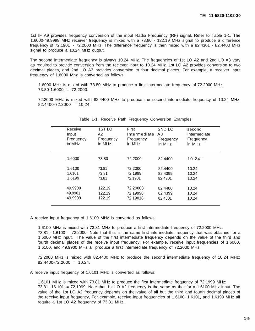
1st IF A9 provides frequency conversion of the input Radio Frequency (RF) signal. Refer to Table 1-1. The1.6000-49.9999 MHz receiver frequency is mixed with a 73.80 - 122.19 MHz signal to produce a differencefrequency of 72.1901 - 72.2000 MHz. The difference frequency is then mixed with a 82.4301 - 82.4400 MHzsignal to produce a 10.24 MHz output.
The second intermediate frequency is always 10.24 MHz. The frequencies of 1st LO A2 and 2nd LO A3 varyas required to provide conversion from the reciever input to 10.24 MHz. 1st LO A2 provides conversion to twodecimal places, and 2nd LO A3 provides conversion to four decimal places. For example, a receiver inputfrequency of 1.6000 Mhz is converted as follows:
1.6000 MHz is mixed with 73.80 MHz to produce a first intermediate frequency73.80-1.6000 = 72.2000.
72.2000 MHz is mixed with 82.4400 MHz to produce the second intermediate82.4400-72.2000 = 10.24.
of 72.2000 MHz:
frequency of 10.24 MHz:
Table 1-1. Receive Path Frequency Conversion Examples
Receive 1ST LO First 2ND LO secondInput A2 Intermediate A3 IntermediateFrequency Frequency Frequency Frequency Frequencyin MHz in MHz in MHz in MHz in MHz
1.6000 73.80 72.2000 82.4400 10 .24 -
1.6100 73.81 72.2000 82.4400 10.241.6101 73.81 72.1999 82.4399 10.241.6199 73.81 72.1901 82.4301 10.24
49.9900 122.19 72.20008 82.4400 10.2449.9901 122.19 72.19998 82.4399 10.2449.9999 122.19 72.19018 82.4301 10.24
A receive input frequency of 1.6100 MHz is converted as follows:
1.6100 MHz is mixed with 73.81 MHz to produce a first intermediate frequency of 72.2000 MHz:73.81 - 1.6100 = 72.2000. Note that this is the same first intermediate frequency that was obtained for a1.6000 MHz input. The value of the first intermediate frequency depends on the value of the third andfourth decimal places of the receive input frequency. For example, receive input frequencies of 1.6000,1.6100, and 49.9900 MHz all produce a first intermediate frequency of 72.2000 MHz.
72.2000 MHz is mixed with 82.4400 MHz to produce the second intermediate frequency of 10.24 MHz:82.4400-72.2000 = 10.24.
A receive input frequency of 1.6101 MHz is converted as follows:
1.6101 MHz is mixed with 73.81 MHz to produce the first intermediate frequency of 72.1999 MHz:73,81 -16.101 = 72,1999. Note that 1st LO A2 frequency is the same as that for a 1.6100 MHz input. Thevalue of the 1st LO A2 frequency depends on the value of all but the third and fourth decimal places ofthe receive input frequency, For example, receive input frequencies of 1.6100, 1.6101, and 1.6199 MHz allrequire a 1st LO A2 frequency of 73.81 MHz.
1-9
TM 11-5820-1102-30
72.1999 MHz is mixed with 82.4399 MHz to produce the second intermediate frequency of 10.24 MHz:82.4399 - 72.1999 = 10.24. Note that the value of the 2nd LO A3 frequency vanes as required to producea second intermediate frequency of 10.24 MHz.
Local Oscillator (LO) and intermediate frequencies may be calculated in the same way for any receive inputfrequency.
2nd IF A8 provides sideband filtering of the 10.24 MHz signal.
Product Detector A7 demodulates the filtered 10.24 MHz input and provides audio output to front panel AUDIOconnectors.
1st LO A2 provides a 73.80 - 122.19 MHz signal to 1st IF A9 for first frequency conversion of the receive input.1st LO A2 also provides a 5.12 MHz time base to Product Detector A7 and 2nd LO A3.
2nd LO A3 provides a 82.4301 - 82.440 MHz signal to 1st IFreceive input.
1-11.2 Receiver Sensitivity All receiver sensitivity determiningA12 PCBs.
Filtering provided by 1st Fitter A11, 2nd Filter A12, 1st IF A9,performance degradation due to strong out-of-band signals is
A9 for secondary frequency conversion of the
circuitry is located on the A7, A8, A9, A11, and
and 2nd IF A8 ensures that the probability ofminimized.
Transceiver noise figure is 13 dB. Noise figure includes the gain (or loss) and noise figures of individual stagesin the receive path.
Correlating this noise figure with the theoretical noise floor of -174 dBm in a 1 Hz bandwith and thetransceiver bandwidth of 2.4 KHz, it can be determined that the transceiver produces 10 dB Signal Into NoiseAnd Distortion (SINAD) for a -117 dBm signal as shown below:
SINAD = Signal Plus Noise Plus Distortion/Noise Plus Distortion
Signal level for 10 dB SINAD is:
-174 dBm + 13 dB(NF) + 10 dB (SINAD) + 34 dB (2.4 kHz BW) = -117 dBm.
1-11.3 Receiver Selectivity Receiver selectivity circuitry is located on the A8 and A9 PCBs.
Selectivity is the measure of the ability of a receiver to select the desired signal and process information witha minimum amount of distortion.
The transceiver provides maximum rejection of out-of-band signals while maintaining a minimum of in-bandamplitude variation and delay distortion. Selectivity is achieved by the use of precision, crystal filters in the firstand second IF stages.
Refer to Figure FO-1. 1st IF A9 has a 30 kHz bandwidth and provides attenuation to out-of-band signals withinthe passband of the low pass fitters in the receiver front end. This filter also minimizes delay distortion toenhance the ability of the transceiver to operate with digital message devices.
2nd IF A8 provides upper sideband (USB) and lower sideband (LSB) crystal fitters. These fitters select thedesired sideband for demodulation. The USB fitter is selected for USB and amplitude modulation equivalent
1-10

TM 11-5820-1102-30
(AME) modes, and the LSB filter is selected for the LSB mode. Both filters have a 2.4 kHz, 6 dB bandwidth.They have a 50 dB bandwidth of 5 kHz, and provide attenuation to those signals within the bandwidth of thefirst IF filter and outside the desired receive channel. These fitters, like the 1st IF A9 crystal filter, minimizedelay distortion.
1-11.4 IF Rejection IF rejection circuitry is located on the A9, A11, and A12 PCBs.
IF rejection is the measure of a receiver’s ability to reduce the effect of a strong signal at the frequency of itsfirst IF. This rejection is usually expressed as a ratio of the signal level required to produce a SINAD of 10 dBat the first IF frequency to the signal level required to produce a SINAD of 10 dB at the desired channelfrequency.
Four factors contribute to the attenuation of an undesired signal appearing at the receiver front end at the firstIF frequency.
First: Within 1st IF A9, the selection of 72.2 MHz for the first IF frequency is far above the highest receivefrequency of 50 MHz to make filtering in subsequent stages more readily achievable.
Second: Within 1st Filter A11 and 2nd Filter A12, band-switched, elliptical function, low pass fitters are usedto attenuate undesired out-of-band signals. They provide significant attenuation to signals just above theirpassband cutoff frequency.
Third: Within 1st IF A9, the transceiver has an additional 7-section, elliptical function, 50 MHz low pass filterlocated immediately before the first receiver mixer to provide additional attenuation for those signals abovethe maximum operating frequency of the radio.
Fourth: Within 1st IF A9, the first mixer maximizes RF-to-lF isolation while minimizing noise figure andinsertion loss.
Overall attenuation provided in the receive signal path to an undesired signal at the frequency of the first IFprovides IF rejection in excess of 70 dB.
1-11.5 Image Rejection Image rejection circuitry is located on the A9, A11, and A12 PCBs.
Transceiver image frequencies fall in a band from 146.0 -194.4 MHz.
Rejection to image frequencies is achieved in much the same way as IF rejection. The switched, ellipticalfunction, low pass filters in 1st Fitter A11 and 2nd Filter A12 greatly attenuate signals that fall in the imagefrequency band. In addition, the 50 MHz, 7-section elliptical function low pass filter located immediately beforethe first mixer on 1st IF A9 provides further attenuation to these signals.
The overall attenuation provided in the receive signal path to undesired signals at the image frequenciesprovides image rejection in excess of 70 dB.
Image rejection is usually expressed as a ratio of the signal level required to produce a SINAD of 10 dB at theimage frequency to the signal level required to produce a SINAD of 10 dB at the desired frequency.
1-11
TM 11-5820-1102-30
Image rejection is the measure of a receiver’s ability to reject a signal whose frequency is defined by thefollowing equation:
Fimg = Frf + 2IF
where:
Fimg = The image frequency of the receiver
Fr f = The desired receive frequency of the receiver
IF = The first intermediate frequency of the receiver
1-11.6 Audio Distortion Audio distortion circuitry is located on the A7 PCB.
Audio distortion is the measure of a receiver’s ability to process an incoming signal in a linear manner withminimum distortion. Audio distortion in the transceiver is less than 5%.
The receive path utilizes low noise, high dynamic range amplifiers. AGC is used in both the first and secondIFs to reduce the level of strong desired signals and to reduce distortion in the later high gain RF and audiostages.
On Product Detector A7, audio amplification stages provide maximum audio output with minimum distortion.
1-12 TRANSMIT PATH CIRCUITRY.
Transmit path circuitry is located on the A2, A3, A7, A8, A9, A10, A11, A12, and A13 PCBs.
Refer to Figure 1-3. The dual conversion transmitter design features operator selectable power levels up to 50watts, band-switched low pass fitters located on 1st Filter A11 and 2nd Filter A12 for harmonic and spuriousattenuation, an audio Voice-Operated Gain Adjusting Device (VOGAD) located on Product Detector A7 forlinearity, and power amplifier protection located on Power Amplifier A13 via ALC located on 1st Mixer A10.Modes of operation are USB, LSB, and AME. The radio provides for CW emission in LSB, USB, and AME viathe CW keyline at front panel audio connectors.
On Product Detector A7, the transmit audio input enters VOGAD circuitry where it is amplified and gain-controlled to provide a constant level to a balanced modulator. Audio input is either voice or Frequency ShiftKey (FSK) tone signal applied at either of the audio input connectors. Input can also be CW tone generatedby an internal audio oscillator.
Radio keying is done on pins C or E of either audio connector. Voice and data audio accessories key theradio via pin C. CW keying accessories key the radio via pin E. When the radio is keyed via pin E, a CWaudio oscillator is activated along with a hangtime circuit.
Refer to Figure FO-2 for audio connector pinouts, which include:
A =B =C =D =E =F =
GroundReceiver Audio OutputKeyline (ground when keyed)Transmit Audio InputCW Keyline (ground when keyed)Not Used
1-12
TM 11-5820-1102-30
On Product Detector A7, the CW audio oscillator generates a tone of approximately 1 kHz. The hangtimecircuit provides a CW hangtime of approximately 1 second. CW can be transmitted in LSB, USB, or AME bykeying the transceiver via pin E.
On Product Detector A7, VOGAD circuitry consists of an audio amplifier with automatic gain control. Levelvariations in the audio input are compensated to maintain a constant input level to a balanced modulator andprevent distortion due to overdriving circuitry in the transmit path. The VOGAD will maintain a constant outputfor input signal levels from 1 to 100 millivolts rms.
The balanced modulator modulates a 10.24 MHz carrier oscillator signal with the audio signal to produce adouble sideband suppressed carrier of 10.24 MHz for the second IF. This signal is filtered by the selectedsideband filter located on 2nd IF A8 to create a suppressed carrier, single-sideband, 10.24 MHz signal.Single sideband filters are the same as those used in the receive path. The LSB fitter is selected in the LSBmode. The USB filter is selected in USB and AME modes. If the AME mode is selected, the carrier signal isreinserted on 1st IF A9 back into the single sideband signal after it is filtered in the USB filter.
On 1st IF A9, the 10.24 MHz second IF signal goes to a mixer where it is mixed with the second LO and up-converted to a 72.2 MHz first IF signal. The 72.2 MHz signal is filtered in first IF crystal fitter circuitry to removemixing products. It is then amplified and sent to another mixer located on 1st Mixer A10 where it is mixed withthe first LO and down-converted to the final RF output frequency. At the output of this mixer, a 50 MHzlowpass filter removes mixing products before the signal is passed to high gain, broadband amplifier circuitry.
On Power Amplifier A13, final power amplifier output is passed to band-switched harmonic fitter circuitry locatedon 1st Filter A11 and 2nd Filter A12 to attenuate all harmonics. It then goes through forward and reflectedpower detectors located on 2nd Fitter A12, and on to an antenna connector located on the front panel.
The output of the forward power detector located on 2nd Fitter A12 is used in the ALC feedback loop on 1stMixer A10 to maintain the output power at the selected level. The output of the reflected power detector on2nd Filter A12 is proportional to the antenna Voltage Standing Wave Ratio (VSWR), and is used in the ALCfeedback Imp to protect the power amplifier by reducing power in proportion to the VSWR magnitude. Anexternal ALC input located on 1st Mixer A10 works in conjunction with battery box circuitry to limit the maximumcurrent from the BA-5590 lithium batteries by controlling RF output power.
On Power Amplifier A13, power amplifier transistors are fully protected from any VSWR, including open andshort circuits. Power amplifier transistors are also protected from excessive temperature by a thermostatmounted in the heatsink used for the final power amplifier transistors. This thermostat automatically reducespower output when heatsink temperature reaches 105°C. The thermostat is located on Power Amplifier A13.When the heatsink cools to 88 degrees C, the power will return to the selected power level.
The emmision of undesired harmonics and spurious signals is minimized to enhance Low Probability ofInterrupt/Low Probability of Detection (LPI/LPD) characteristics. Two factors contribute to the low level ofspurious and harmonic emmissions from the transmitter.
First: Dual conversion design allows intermediate frequencies to be chosen so that undesired mixingproducts and spurious signals can be easily attenuated prior to high gain, broadband power amplifierstages.
Second: Band-switched, elliptical function’ low pass filters attenuate power amplifier harmonics and anyspurious signals that do reach the power amplifier.
On 1st Fitter A11 and 2nd Fitter A12, harmonics are kept at a minimum of 50 dB below the desired outputsignal. Circuitry to suppress harmonics is located on 1st Filter A11 and 2nd Filter A12.
1-13

TM 11-5820-1102-30
1-12.1 Transmit Frequency Conversion Refer to Figure 1-3. Product Detector A7 accepts audio input fromthe front panel AUDIO connectors and generates a suppressed carrier double sideband signal at 10.24 MHz.
2nd IF A8 provides sideband filtering of the 10.24 MHz signal.
1st IF A9 mixes the 10.24 MHz input with a 82.4301 - 82.4400 MHz signal from 2nd LO A3. It provides adifference frequency output of 72.1901 -72.2000 MHz.
1st Mixer A10 mixes the difference frequency with a 73.80 - 122.19 MHz signal to produce a transmit frequencyoutput of 1.6 - 49.9999 MHz.
The transmitter output frequency varies from 1.6000 - 49.9999 MHz in 100 Hz (.0001 MHz) increments. Referto Table 1-2. The first intermediate frequency is always 10.24 MHz. The frequencies of 2nd LO A3 and 1stLO A2 vary as required to provide conversion from 10.24 MHz to the transmit output frequency. 1st LO A2provides conversion to two decimal places and 2nd LO A3 provides conversion to four decimal places. Forexample, a transmitter output frequency of 1.6000 MHz is converted as follows:
10.24 MHz is mixed with 82.4400 MHz to produce a second intermediate frequency of 72.2000 MHz:82.4400 - 10.24 = 72.2000.
72.2000 MHz is mixed with 73.80 MHz to produce a transmit output frequency of 1.6000 MHz:73.80 - 72.2000 = 1.6000.
Table 1-2. Transmit Frequency Conversion Examples
First 2ND LO Second 1ST LO TransmitIntermediate A3 Intermediate A2 outputFrequency Frequency Frequency Frequency Frequencyin MHz in MHz in MHz in MHz in MHz
10.24 82.4400 72.2000 73.80 1.6000
10.24 82.4400 72.2000 73.81 1.610010.24 82.4399 72.1999 73.81 1.610110.24 82.4301 72.1901 73.81 1.6199
10.24 82.4400 72.2000 122.19 49.990010.24 82.4399 72.1999 122.19 49.990110.24 82.4301 72.1901 122.19 49.9999
For a transmit output frequency of 1.6100 MHz, conversion is as follows:
10.24 MHz is mixed with 82.4400 MHz to produce a second intermediate frequency of 72.2000 MHz:82.4400 - 10.24 = 72.2000. Note that this is the same frequency that was obtained for a 1.6000 MHztransmit output. The value of the second intermediate frequency depends on the value of the third andfourth decimal places of the transmit output frequency. For example, transmit frequencies of 1.6000,1.6100, and 49.9900 MHz all require a second intermediate frequency of 72.2000 MHz.
1-14

TM 11-5820-1102-30
FIGURE 1-3. Transceiver, RT-1648 transmit path block diagram
1-15

TM 11-5820-1102-30
72.2000 MHz is mixed with 73.81 MHz to produce the transmit output frequency: 73.81 - 72.2000 = 1.6100.The frequency value of 1st LO A2 depends on the value of all but the third and fourth decimal places ofThe transmit output frequency. For example, transmit output frequencies of 1.6100, 1.6101, and 1.6199 MHzall require a 1st LO A2 frequency of 73.81 MHz.
LO and intermediate frequencies may be calculated in the same way for any transmit output frequency.
Power amplifier A13 provides transmit power amplification up to 50 watts. Input is from 1st Mixer A10 at a level
of +20 dBm, nominal.
Transmit output in the range of 1.6 - 11.4399 MHz is filtered by one of four filters on 1st Filter A11. Output inthe range of 11,44 - 49.9999 MHz is filtered by one of three filters on 2nd Fitter A12. The filter to be used isselected by relay. ALC detectors on 2nd Filter A12 work with ALC attenuators on 1st Mixer A10 to maintainconstant output power.
1st LO A2 provides a variable 73.80 - 122.19 MHz signal to 1st mixer A10. The 73.80 - 122.19 MHz is mixedwith 72.1901 -72.2000 MHz to produce the final transmit frequency. 1st LO A2 also provides a 5.12 MHz timebase to Product Detector A7 and 2nd LO A3.
2nd LO A3 provides a 82.4301 - 82.4400 MHz signal to 1st IF A9.
1-12.2 RF Output Power RF output power circuitry is located on the A13 PCB.
The transceiver is designed primarily for short burst transmissions, providing up to 50 watts Peak EnvelopePower (PEP) and average power across the 1.6 to 50 MHz band while maintaining linearity. Power output isselectable at 5, 10, 20, and 50 watts.
1-12.3 Intermodulation Distortion Intermodulation distortion determining circuitry is located on the A13 PCB.
Transceiver intermodulation products are kept a minimum of 20 dB below the desired output level.
1-12.4 Carrier Suppression Carrier suppression circuitry is located on the A7 and A8 PCBs.
Transceiver carrier suppression is a sum of the attenuation at the carrier frequency (10.24 MHz) provided bythe selected sideband filter plus the suppression obtained in the balanced modulator.
The attenuation provided by sideband fitters at the carrier frequency is less than 10 dB. The balancedmodulator provides a minimum carrier suppression of 50 dB. Adding this to the attenuation provided by thesideband fitters results in a minimum carrier suppression greater than 50 dB.
1-12.5 OPPOsite Sideband Suppression Opposite sideband suppression circuitry is located on the A8 PCB.
Unlike carrier suppression, opposite sideband suppression is provided only in the selected sideband filter. A10-pole crystal filter design is used to maintain opposite sideband suppression at 50 dB and to maintain alinear phase, The result is a minimum of 50 dB attenuation at 1 kHz from the carrier frequency in the oppositesideband of each fitter.
1-12.6 Output Load Impedance Output load impedance circuitry is located on the A13 PCB.
1-16

TM 11-5820-1102-30
Transmitter output impedance is determined by power amplifier final stage output impedance and low passharmonic filter impedances.
Power Amplifier A13 is designed for a 50 ohm output impedance. Filters are designed for both 50 ohm inputand output impedances. This results in a nominal RF output load impedance at the antenna terminals of 50ohms, unbalanced, with respect to ground.
1-12.7 Voltaqe Standing Wave Ratio (VSWR) VSWR circuitry is located on the A10, A12, and A13 PCBs.
The transceiver provides as much power as possible into antennas with high VSWR while still providing a highdegree of protection to the final power amplifier transistors from the high reflected power associated with theseantennas. This is done by ALC loop and reflected power detector circuitry which gradually degrades theforward power output as VSWR increases.
Forward output power is reduced by less than 1.5/VSWR for VSWRs greater than 2:1. Full forward poweroutput is provided for VSWRs up to 2:1.
1-13 SYNTHESIZER CIRCUITRY.
All synthesizer circuitry is located on the A2 and A3 PCBs.
Transceiver synthesizer circuitry provides all LO, reference, and clock signals required by the radio. Thisincludes the first LO and second LO signals used for frequency conversion in the receive and transmit paths,the 5.12 MHz signal doubled to generate the Beat Frequency Oscillator (BFO) signal used in the productdetector in the receive path, the balanced modulator in the transmit path, and the clock signal for themicroprocessor controller.
The synthesizer is of indirect digital design that combines low power Complementary Metal Oxide Semi-Conductor Very Large Scale Integration (CMOS VLSI) technology with custom hybrid microcircuitry and a highstability Temperature Compensated Crystal Oscillator (TCXO) reference. Synthesizer power dissipation isminimal.
Stability is attained by referencing all the synthesizer signals to the TCXO to maintain overall frequencyaccuracy and stability.
Figure 1-4 illustrates the synthesizer block diagram.
First LO circuitry is contained on the A2 module, and consists of a single Phase Locked Loop (PLL) with a 10kHz reference.
The first LO signal varies from 73.80 - 122.19 MHz in 10 kHz steps. Two Voltage-Controlled Oscillators (VCOs)are used to cover the first LO range. These oscillators are of low-noise design, and are band-switched at afrequency of 25 MHz with each oscillator covering a range of approximately 25 MHz.
Second LO circuitry is contained on the A3 module, and consists of two PLLs mixed to provide the second LOoutput. One loop consists of an oscillator locked to an 8 kHz reference. This oscillator varies from85.608 - 86.400 MHz in 8 kHz steps. This signal is then divided by 80 to produce a 1.0701 - 1.0800 MHzsignal that varies in 100 Hz steps. The other loop consists of a fixed frequency, 81.36 MHz oscillator, lockedto a 40 kHz reference. This signal is mixed with the 1.0701 - 1.0800 MHz signal to produce an 82.4301 - 82.44MHz signal that is filtered and amplified to produce the second LO output signal.
1-17

TM 11-5820-1102-30
1-18
FIGURE 1-4. Transceiver synthesizer
TM 11-5820-1102-30
On the A3 card, the crystal filter attenuates the sidebands from the mixer and insures the spectral purity ofthe second LO.
The TCXO reference oscillator is also located on the A2 module. It contains a thermistor feedback network tostabilize frequency over the operating temperature range. It provides reference frequencies for the PLLs, anda 5.12 MHz output for the BFO in the receiver/exciter and the clock in the controller circuitry.
1-13.1 Frequency Range Frequency range determining circuitry is located on the A2 and A3 PCBs.
The transceiver covers an expanded frequency range of 1.6-50 MHz in 100 Hz steps. The transceiver utilizesboth 1st LO A2 and 2nd LO A3 to cover the frequency range.
1st LO A2 provides 10 kHz, 100 kHz, 1 MHz, and 10 MHz frequency steps.
2nd LO A3 provides 100 Hz and 1 kHz frequency steps.
In receive operations, the 1.6000 - 49.9999 MHz receive frequency is mixed with the 73.80 - 122.19 MHz firstLO frequency to produce the first IF of 72.1901 - 72.2000 MHz. This signal is mixed with the 82.4301 - 82.44MHz second LO frequency to produce the constant second IF of 10.24 MHz.
In transmit operations, the path is reversed but conversion frequencies are the same, with the modulated 10.24MHz second IF signal being eventually up-converted to a 1,6000 - 49.9999 MHz output.
1-13.2 Frequency A c c u r a c y Frequency accuracy determining circuitry is located on the A2 PCB.
To insure the highest level of frequency accuracy and stability, a TCXO is used as the reference oscillator. All
other oscillators are locked to this reference. The TCXO has an overall stablity of 1 part per million (ppm),
including the effects of variations in battery voltage and service conditions.
1-14 POWER SUPPLY AND DISTRIBUTION CIRCUITRY.
Power supply and distribution circuitry is located on all transceiver PCBs.
The transceiver does not contain a DC-to-DC converter. This greatly reduces EMI both internally and externallyto the radio.
The transceiver utilizes three terminal series regulators on critical circuits to provide regulation and isolation.
1-14.1 Reverse Voltage Protection Reverse voltage protection is a mechanical function. The transceiver andbattery box are mechanically keyed to prevent accidental application of reverse voltage to the transceiver.
1-14.2 Power Drain Power drain circuitry is located on all PCBs.
The transceiver is designed for low power consumption. Circuitry not needed for a particular function, whethertransmit or receive, is switched off when not in use.
1-19
TM 11-5820-1102-30
Transmit power is limited to a maximum of 20 watts when operating with two BA-5590 batteries.When batteries are combined, transmit power may be limited dependent upon the relative stateof the battery charge.
Four output power levels (5, 10, 20, and 50 watts) allow the operator to select minimum output power requiredto achieve reliable communications.
The battery box also contains power drain circuitry that is active only when the battery box is connected to theradio.
1-15 CONTROL AND INTERFACE CIRCUITRY.
All control and interface circuitry is located on the A1 PCB and A22 Assembly.
Refer to the AN/PRC-132 Radio Set Operator’s and Unit Maintenance manual (TM 11-5820-1102-12) for adescription of radio interfaces and controls.
1-15.1 Secure Lighting All secure lighting circuitry is located on the A22 Assembly.
Refer to the AN/PRC-132 Radio Set Operator’s and Unit Maintenance manual (TM 11-5820-1102-12) for adescription of secure lighting capabilities.
1-15.2 Electrical Interface All microprocessor control circuitry is located on the A1, A15, and A16 PCBs.
Electrical interfaces include external connections from the front and rear panels to internal radio circuitry, andinternal control and signal interfaces within the transceiver.
External interfaces include the battery connector at the rear panel and the audio connectors and control push-buttons located at the front panel.
Refer to Figure 1-5. On Processor A1, microprocessor control of timing and switching signals is required forfrequency synthesis on 1st LO A2 and 2nd LO A3, filter switching on 1st Fitter A11 and 2nd Filter A12, andT/R switching throughout. The microprocessor is interrupt-driven to minimize EMI from clock and data signalsin receiver circuitry and to reduce external spurious emissions. This means that the processor and associatedcircuitry is inactive until the operator changes one of the front panel control inputs, and causes an interrupt.At this time, control circuitry activates to perform the appropriate command, and then returns to an inactivecondition.
On 1st Fitter A11 and 2nd Filter A12, the microprocessor-based control system has a bus architecture andconsists of the microprocessor, an EPLD, an EPROM, RAM, an LCD, and control bus drivers for interfacinginternally to the other sections of the radio.
Front panel controls and radio keylines interface to the EPLD. The EPLD encodes input commands intoprocessor logic signals and provides a wake-up call for the microprocessor.
The microprocessor, along with associated EPROM and RAM, generates the required radio commands andoutputs them through control bus drivers to associated transceiver circuitry.
1-20

TM
11-5820-1102-30
FIG
UR
E
1-5. B
lock diagram
, interface
and control
circuitry
1-21

TM 11-5820-1102-30
The EPROM contains a system timing program. It contains the program required by the processor to perform
desired functions.
The RAM stores parameters programmed by the operator, such as frequency and channel information. OnProcessor A1, the lithium battery provides backup power for RAM circuitry when the radio is off.
The LCD displays frequency and channel information, and includes a "T" annuciator to indicate when the radio
is in transmit or when a transmit frequency is displayed.
All internal control interface to other radio sections is routed through the Interconnect Board A14.
1-22

TM 11-5820-1102-30
CHAPTER 2
DIRECT SUPPORT MAINTENANCE
Section I. REPAIR PARTS AND SPECIAL TOOLS
2-1 COMMON TOOLS, SPECIAL TOOLS, TMDE, AND SUPPORT EQUIPMENT.
Refer to the Repair Parts and Special Tools List (TM 11-5820-1102-23P) and to the Maintenance Allocation Chart(TM 11-5820 -1102-1 2) for information concerning special tools requirements, TMDE, and supportequipment requirements for Direct Support maintenance actions.
Section Il. MAINTENANCE PROCEDURES
2-2 ASSEMBLY AND DISASSEMBLY.
WARNING
Processor board A1 contains a Iithium battery. The lithium battery contains flammableorganic materiels. Incorrect handling may cause explosion. Do not short battery leadstogether in any fashion, expose to extreme heat for more than 5-10 seconds, immerse inwater or any cleaning solution, make a mistake in polarity, drop, or strike the battery.
Circuit A13 contains BERYLLIUM OXIDE (BeO) CERAMICS. The dust or fumes fromBERYLLIUM OXIDE CERAMICS are HIGHLY TOXIC and breathing them can result in seriouspersonal injury or DEATH. For local guidance/assistance on disposal of unserviceable circuitcard A13, contact your servicing Defense Reutilization and Marketing Office (DRMO).
CAUTION
CAUTION. CONTAINS PARTS AND ASSEMBLIES SUSCEPTIBLE TO DAMAGE BYELECTROSTATIC DISCHARGE (ESD).
Transceiver circuitry is on replaceable units Printed Circuit Boards (PCBs) that do not require desoldering of
wires or parts for access. PCBs can be tested in the radio with cables. All replaceable modules in the
transceiver are electrically interchangeable at the Direct Support maintenance level. In all cases following
module replacement, the transceiver is completely operational without alignment.
2-1

TM 11-5820-1102-30
2-2.1 Card Cage Removal and Assembly
2-2.1.1 Disassembly.
a. To access plug-in circuit cards, remove four hex screws from the control panel. Refer to Figure 2-1.
b. Pull chassis out of housing. All plug-in circuit cards are keyed to prevent insertion in the wrong slot.Figure 2-1 also shows gasket and o-ring location.
2-2.1.2 Assembly. Assemble card cage in reverse order of disassembly.
2-2.2 Removal and Assembly of Interconnect Board A14
2-2.2.1 Disassembly.
a. Remove power from transceiver.
b. Remove all cards from transceiver Interconnect Board A14, except for Control Panel A22.
c. Remove 6 hex screws and A14 cover.
d. Remove 2 Phillips screws (Refer to Figure 2-2).
e. Lift Interconnect Board A14 from front to rear.
2-2.2.2 Assembly. To assemble, perform disassembly steps 2-5 in reverse order.
2-2.3 Removal and Assembly of Control Panel A22
2-2.3.1 Disassembly.
a Remove power from transceiver.
b. Refer to Figure 2-3. Unscrew and disengage 4 Phillips screws, but do not remove them.
c. With Interconnect Board A14 down, place transceiver on a flat surface.
d. Press firmly down on card cage while lifting Control Panel A22 up and away.
NOTE
Do not turn Control Panel A22 face down or allow removal screws to fall out.
2-2.3.2 Assembly.
a. Insure that all 4 stand-off posts and screws are properly aligned.
b. Place card cage assembly with Interconnect Board A14 facing you and J15 down. Insure card cage islevel with J15 and guide pins extending beyond the flat surface.
c. Gently insert A22P2 and P1 (RF connector) into A14J2 and J1.
2-2

TM 11-5820-1102-30
FIGURE 2-1. Removing chassis from housing, gasket and o-ring location
2-3

TM 11-5820-1102-30
FIGURE 2-2. Location of Interconnect Board A14 hex and Phillips retaining screws
2 - 4

TM 11-5820-1102-30
FIGURE 2-3. Front panel assembly removal
2 - 5
TM 11-5820-1102-30
d. Insure all screws are alined with card cage and tighten.
2-2.4 Removal and Assembly of Front Panel Bezel
2-2.4.1 Disassembly.
a. Refer to Figure 2-1. Loosen the four bezel mounting screws.
b. Pull bezel out of front panel.
2-2.4.2 Assembly.
a. Place bezel in front panel.
b. Use mounting screws to attach bezel to front panel.
2-2.5 Removal and Assembly of Power Amplifier A13
2-2.5.1 Disassembly.
a. Remove power from transceiver.
b. Remove transceiver from case. Refer to Figure 2-1.
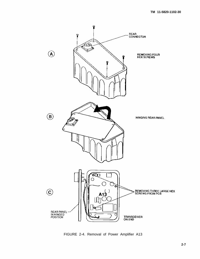
c. Place housing assembly on flat surface with battery plug (P2) facing away from you. Refer toFigure 2-4.
d. Remove 4 hex screws from Power Amplifier A13.
e. Carefully lift rear paneI and hinge to left.
f. Loosen the 3 large PCB hex screws.
g. Position rear cover over assembly and, while holding in place, turn housing over.
h. Reach into housing assembly and gently push P15 until free from housing.
2-2.5.2 Assembly.
a Install Power Amplifier A13 and start, but do not tighten, the 3 PCB hex screws.
b. Insert transceiver snugly into housing and tighten A13 PCB hex screws.
c. Remove transceiver from case and reinstall to insure proper alinement of J15/P15.
d. If needed, change bad o-rings on rear panel screws.
e. Secure rear panel.
2-6
TM 11-5820-1102-30
FIGURE 2-4. Removal of Power Amplifier A13
2-7
TM 11-5820-1102-30
2-2.6 Disassembly and Assembly of Battery Box to Allow Access to Q1, CR1, and CR2
2-2.6.1 Disassembly.
a.
b.
c.
d.
e.
f.
g.
Remove battery box rear cover.
Remove batter(ies) if installed.
Refer to Figure 2-5. Remove 6 hex screws and washers from the PCB retaining frame.
Grasp P2 and carefully lift PCB from battery box and rotate 90 degrees counterclockwise.
Hinge PCB over to left to allow access to Q1, A1A2A1CR1, A1A2A1CR2, P1, and P2.
To remove Q1, unsolder leads and unscrew the two Phillips screws, being sure to retain the thermalgasket under Q1.
To remove A1A2A1CR1 and A1A2A1CR2, unsolder wires from leads and unscrew.
2-2.6.2 Assembly, Assemble battery box in reverse order of disassembly.
2-3 REPAIR.
Direct Support maintenance of the AN/PRC-132 Radio Set includes repair down to the card level.
Flathead screws required in the card cage assembly are secured with retaining compound.
In addition, front panel knobs, front and rear cover O-rings, and hexseals used on the ENTER, FREQ SEL, andCHAN buttons can be removed and replaced for maintenance. These items are contained in a running spareskit. Set screws on flatted shafts are used to secure front panel control knobs.
Battery box repair includes replacement of batteries, Q1, A1A2A1CR1, A1A2A1CR2, and connectors P1 and P2.
2-8

TM 11-5820-1102-30
FIGURE 2-5. Battery box disassembly
2-9/(2-10 blank)

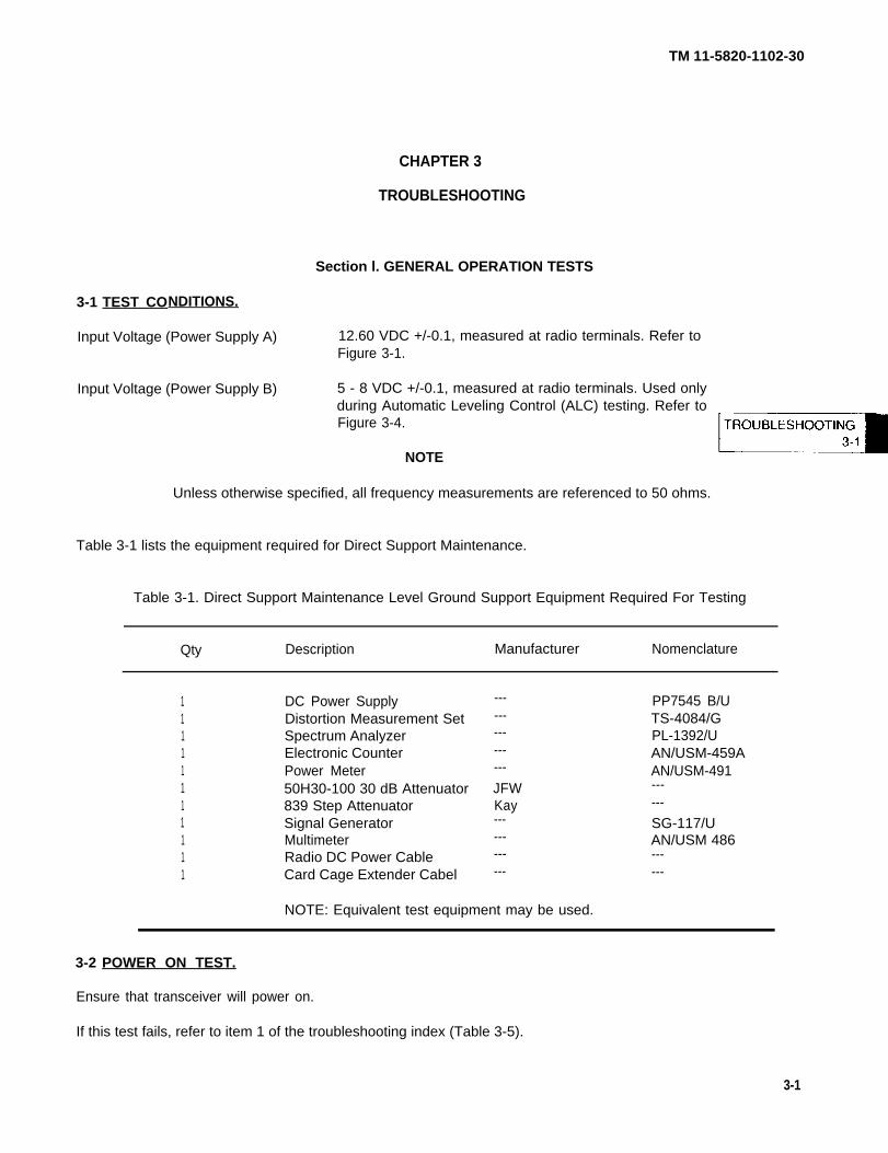
TM 11-5820-1102-30
CHAPTER 3
TROUBLESHOOTING
Section l. GENERAL OPERATION TESTS
3-1 TEST CONDITIONS.
Input Voltage (Power Supply A)
Input Voltage (Power Supply B)
12.60 VDC +/-0.1, measured at radio terminals. Refer toFigure 3-1.
5 - 8 VDC +/-0.1, measured at radio terminals. Used onlyduring Automatic Leveling Control (ALC) testing. Refer toFigure 3-4.
NOTE
Unless otherwise specified, all frequency measurements are referenced to 50 ohms.
Table 3-1 lists the equipment required for Direct Support Maintenance.
Table 3-1. Direct Support Maintenance Level Ground Support Equipment Required For Testing
Qty Description Manufacturer
11111111111
DC Power SupplyDistortion Measurement SetSpectrum AnalyzerElectronic CounterPower Meter50H30-100 30 dB Attenuator839 Step AttenuatorSignal GeneratorMultimeterRadio DC Power CableCard Cage Extender Cabel
---------------
JFWKay------------
Nomenclature
PP7545 B/UTS-4084/GPL-1392/UAN/USM-459AAN/USM-491------
SG-117/UAN/USM 486------
NOTE: Equivalent test equipment may be used.
3-2 POWER ON TEST.
Ensure that transceiver will power on.
If this test fails, refer to item 1 of the troubleshooting index (Table 3-5).
3-1

TM
3-3
11-5820-1102-30
FREQUENCY PROGRAMMING AND SECURE LIGHTING TEST.
Ensure that receive and transmit frequencies can be programmed, and that frequency and channel scan both
work correctly. Ensure that secure lighting function works.
3-3.1 Load Frequencies for Channels 1-11 Refer to the matrix for loading channels 1-11.
CH
3-3.1.1
123456789
1011
RECEIVE FREQUENCY
2.80002O.100049.99991.60002.01003.45005.64009.220015.075024.650040.2900
TRANSMIT FREQUENCY
2.900020.100049.99991.60002.01003.45005.64009.220015.075024.650040.2900
Setting Channels. Use the following procedures to load frequencies for each channel to be set.
NOTE
Leading zeros must be entered. Trailing zeros must be entered for channel. Leading zerosare displayed for channel.
a. Set POWER switch to RX position.
(1) Press CHAN to display current channel in the following format: “HL XX" (XX = two-digit channelnumber). If channel is correct, press enter.
(2) Perform the following to program a new channel.
(a) Turn select switch to the first digit of the desired channel number. Examples: To set channel 10,turn switch to 1. To set channel 09, turn switch to 0.
CAUTION
If the Liquid Crystal Display (LCD) shows a single letter "H" or series of the letter "H" whenyou press the FREQ SEL button, the transceiver is in the memory clear sequence. PressCHAN or turn the transceiver off to abort the clear operation. Then restart the procedure youwere performing.
(b) Press FREQ SEL to display digit selected.
(c) Turn select switch to the second digit of the channel number. Examples: To set channel 10, turnswitch to 0. To set channel 09, turn switch to 9.
3-2

TM 11-5820-1102-30
(d) Press FREQ SEL to display selected channel.
(e) If the channel displayed is not correct, go back to step a(2)(a).
(f) Press ENTER to display current receive frequency for selected channel.
b. Program receive frequency as follows:
Leading zeros must be entered. Trailingzeros are not displayed for frequency.
NOTE
zeros need not be entered for frequency. Leading
(1) If frequency shown on LCD is the desired receive frequency, press ENTER. Go to step c.
(2) If frequency shown is not the desired recieve frequency, proceed as follows:
(a) Turn select switch to the first digit of the recieve frequency.to 2. To set 9.9999 MHz, turn switch to 0. In this second09.9999 MHz.
Examples: To set 20 MHz, turn switchexample, you are really setting
CAUTION
If the LCD shows a single letter "H" or series of the letter "H" when you press the FREQ SELbutton, the transceiver is in the memory clear sequence. Press CHAN or turn the transceiveroff to abort the clear operation. Then restart the procedure you were performing.
(b) Press FREQ SEL to display digit selected. If display is incorrect, press CHAN, then ENTER, andgo back to step b(2)(a).
(c) Turn select switch to the next digit of the receive frequency and press the FREQ SEL button. LCDwill show digit selected. Repeat this step until the required digits have been entered. If any entriesare incorrect, press CHAN, then ENTER, and go back to step b(2)(a).
(d) When you have entered the required digits, press ENTER to store receive frequency in memory.
NOTE
At this point, LCD shows a small "T" above the decimal point of the frequency display. Thisindicates that frequency shown is the transmit frequency.
c. Program transmit frequency as follows:
(1) If frequency shown on LCD is the desired transmit frequency, press ENTER.
(2) If frequency shown is not the desired transmit frequency, enter a new transmit frequency in the samemanner as you would a new receive frequency. When you have entered transmit frequency, pressENTER. Transmit frequency is now stored in memory.
3-3

TM 11-5820-1102-30
If this test fails, refer to items 2 and 3 of the troubleshooting index Table 3-5).
3-3.2 Frequency and Channel Scan Perform the following to verify that frequencies and channels can bescanned.
3-3.2.1 Scanning Frequencies.
a. Set POWER switch to any
b. Turn select switch to UDB
To scan receive frequencies in steps of 100 Hz, proceed as follows.
operating position and select operating mode.
position.
CAUTION
If the LCD shows a single letter "H" or series of the letterbutton, the transceiver is in the memory clear sequence.
"H" when you press the FREQ SELPress CHAN or turn the transceiver
off to abort the clear operation. Then restart the procedure you were performing.
c. Press FREQ SEL to display the current channel in the following format: "PL XX" (XX = two-digit channelnumber).
d. If a different channel is required, proceed as follows:
(1) Turn select switch to the first digit of the desired channel number. Examples: To set channel 10, turnswitch to 1. To set channel 09, turn switch to 0.
(2) Press FREQ SEL to display the digit selected.
(3) Turn select switch to the second digit of the channel number. Examples: To set channel 10, turnswitch to 0. To set channel 09, turn switch to 9.
(4) Press FREQ SEL to display channel selected. If channel displayed is not correct, go back to stepd(1).
e. Press ENTER to display the receive frequency.
f. At this point, frequency scan operation is enabled. To increase frequency, press FREQ SEL Todecrease frequency, press ENTER.
g. To exit frequency scan, turn select switch to any number and press CHAN.
3-3.2.2 Scanning Channels. To scan through 11 channels, proceed as
a. Set POWER switch to any operating position and select operating
b. Press CHAN to display current channel in the following format:number).
follows.
mode.
“HL XX” (XX = two-digit channel
3-4

TM 11-5820-1102-30
NOTE
Receive frequency, not channel number, is displayed during scan.
c. If a different starting channel is required, proceed as follows:
(1) Turn select switch to the first digit of the desired channel number. Examples: To set channel 10, turnswitch to 1. To set channel 09, turn switch to 0.
CAUTION
If the LCD shows a single letter "H" or series of the letter “H” when you press the FREQ SELbutton, the transceiver is in the memory clear sequence. Press CHAN or turn the transceiveroff to abort the clear operation. Then restart the procedure you were performing.
(2) Press FREQ SEL to display the digit selected.
(3) Turn select switch to the second digit of the channel number. Examples: To set channel 10, turnswitch to 0. To set channel 09, turn switch to 9.
(4) Press FREQ SEL to display both digits selected. If the channel displayed is not correct, go back tostep c(1).
d. Press ENTER. The receive frequency will be displayed.
e. Turn select switch to SCAN.
f. At this point, channel scan is enabled. Press FREQ SEL to increase the channel.
NOTE
Channel scan cycles through 11 channels. Each time FREQ SEL is pressed, one is addedto the current channel until the eleventh channel is reached. After the eleventh channel, thescan returns to the first channel. For example, if the starting channel is 10, scan will be asfollows: 10, 11, 12, 13, 14, 15, 16, 17, 18, 19, 20, 10, 11, etc.
Scanning stops at channel 99 even if fewer than eleven channels have been scanned. Forexample, if the starting channel is 95, scan will be as follows: 95, 96, 97, 98, 99, 95, 96, etc.
g. To exit channel scan, turn select switch to any number and press CHAN.
If this test fails, refer to items 2 and 3 of the troubleshooting index (Table 3-5).
3-3.3 Secure Lighting Perform the following procedure to verify that secure lighting function works:
a. Use CHAN button to turn LCD secure lighting on or off.
b. Press CHAN button twice to turn lighting on.
3-5

TM 11-5820-1102-30
c. Press CHAN button twice to turn lighting off.
d. Be sure to turn secure lighting off when it is not needed to prolong battery life.
If this test fails, refer to items 2 and 3 of the troubleshooting index (Table 3-5).
3-4 RECEIVER TESTS.
CAUTION
Do not key transceiver during receive tests. Leave transceiver in RX only position. Testequipment attached to the ANT connector may be damaged if transceiver is keyed.
3-4.1 No RX If unable to receive, refer to item 4 of the troubleshooting index (Table 3-5).
3-4.2 Low Audio If audio is low or weak, refer to item 5 of the troubleshooting index (Table 3-5).
3-4.3 Sensitivity Test Perform sensitivity test as follows:
a. Connect transceiver to test equipment as shown in Figure 3-1.
b. Perform the following steps:
(1) Set transceiver to the frequency and mode listed in Table 3-2.
(2) Set signal generator to the frequency listed in Table 3-2.
(3) Adjust signal generator output level to -117 dBm or +.316 microvolts and adjust volume to 1.5 Voltsroot-mean-square (Vrms) on distortion measurement set. With a 1 kHz receive tone, Signal Into Noiseand Distortion (SINAD) reading on the distortion measurement set should be 10 dB or greater.
(4) Record SINAD output level.
c. Repeat steps b (1) through b(4) for each entry in Table 3-2.
d. If all recorded readings are greater than or equal to 10 dB SINAD, transceiver has passed sensitivity test.
e. If this test fails, refer to item 6 of the trouble shooting index (Table 3-5).
3-6

TM 11-5820-1102-30
* FREQUENCY STABILITY MUST BE 0.1 ppm (1 x10⁻⁷) OR BETTER
FIGURE 3-1. Test equipment setup for receive and sensitivity tests
3-7

TM 11-520-1102-30
Table 3-2. Settings for Sensitivity Test
Channel Transceiver Transceiver Signal GeneratorFrequency Mode Frequency
5 2.0100 MHz USB 2.0110 MHz6 3.4500 MHz LSB 3.4490 MHz7 5.6400 MHz LSB 5.6390 MHz8 9.2200 MHz AME 9.2210 MHz9 15.0750 MHz AME 15.0760 MHz
10 24.6500 MHz USB 24.6510 MHz11 40.2900 MHz USB 40.2910 MHz
3-4.4
a.
b.
Audio Distortion Test Perform audio distortion test as follows:
Connect transceiver to test equipment as shown in Figure 3-1.
Perform the following steps:
(1) Set transceiver to frequency and mode listed in Table 3-2 (Channel 5).
(2) Set signal generator to channel 5 frequency listed in Table 3-2.
(3) Adjust signal generator output level to -80 dBm/22.4 microvolts.
(4) On the distortion measurement set, adjust volume output to 2.25 Vrms, minimum.
(5) A reading of no more than 5% should be shown on the distortion measurement set.
If this test fails, refer to
3-5 TRANSMIT TESTS
item 7 of the troubleshooting index (Table 3-5).
CAUTION
Ensure all test equipment is properly adjusted before keying transceiver. Key transceiver forthe minimum amount of time required to take a reading. Do not leave transceiver keyed formore than 60 seconds at a time, or exceed a 1:9 duty cycle. Failure to observe this cautionmay result in degraded performance, causing test failure.
NOTE
When keyed for an excessive period of time, the transceiver automatically protects itselfagainst heat build-up by reducing the transmit power output level.
3 - 8

TM 11-5820-1102-30
3-5.1
a.
b.
c.
d.
NOTE
All power readings in the following steps are adjusted for the 30 dB attenuator between theantenna output of the transceiver and the power meter. For 50 watts (+47 dBm) output fromthe transceiver, the power meter will read 50 milliwatts (+17 dBm). For 20 Watts (+43 dBm),the power meter will read 20 milliwatts (+13 dBm). For 10 watts (+40 dBm), the powermeter will read 10 milliwatts (+10 dBm). For 5 watts (+37 dBm) the power meter will read5 milliwatts (+7 dBm). For Amplitude Modulation Equivalent (AME) operations you will read3 dB less than the listed levels when using an average power meter.
Transmit Power Out Test Perform transmit power out test as follows:
Connect transceiver to test equipment as shown in Figure 3-2.
Set transceiver for transmit at 50 watts.
Set the distortion measurement set audio generator for 1000 Hz at 5 millivolts root-mean-square (rms).
Perform the following steps:
(1) Program the transceiver to the frequency and mode listed in Table 3-3.
(2) Key
e. Repeat
the transceiver and record the output power for each setting.
steps d(l) through d(2) for each entry in Table 3-3.
Table 3-3. Settings for Transmit Power Output Test at 50 Watts
Channel Transceiver TransceiverFrequency Mode
56789
10113
2.0100 MHz3.4500 MHz5.6400 MHz9.2200 MHz15.0750 MHz24.6500 MHz40.2900 MHz49.9999 MHz
USBLSBUSBLSBUSBUSBUSBUSB
f. If the output power, as read on the power meter, is in all cases between 40 and 63+18 dBm), the transceiver has passed the transmit power output test at 50 watts.
Allowable variation without
g. Set transceiver for transmit at
NOTE
attenuation from 50 watts is +47 dBm +/-1 dB.
5 watts and wait 5-10 seconds.
milliwatts (+16 to
3-9

TM 11-5820-1102-30
h. Perform the following steps:
(1) Set transceiver to frequency and mode listed in Table 3-4.
Table 3-4. Settings for Transmit Power Output Test at 5, 10, and 20 Watts
Channel Transceiver TransceiverFrequency Mode
1 2.8000 MHz USB2 20.1000 MHz LSB3 49.9999 MHz USB
(2) Key transceiver and record the output voltage for each setting.
i. Repeat steps h(1) through h(2) for each entry in Table 3-4.
j. If the output power, as read on the power meter, is in all cases between 4.0 and 6.3 milliwatts (+6 to+8 dBm), the transceiver has passed the transmit power output test at 5 watts.
NOTE
Allowable variation without attenuation from 5 watts is +37 dBm +/-1 dB.
k. Set transceiver for transmit at 10 watts.
l. Perform the following steps:
(1) Set transceiver to the frequency and mode listed in Table 3-4
(2) Key transceiver and record the output voltage for each setting.
m. Repeat steps I(1) through I(2) for each entry in Table 3-4.
n. If the output power, as read on the power meter, is in all cases between 7.9 and 12.6 milliwatts (+9 to+11 dBm), the transceiver has passed the transmit power output test at 10 watts.
Allowable variation without
o. Set transceiver for transmit at
p. Perform the following steps:
Set transceiver to the
NOTE
attenuation from 10 watts is +40 dBm +/-1 dB.
20 watts.
frequency and mode listed in Table 3-4.
3-10
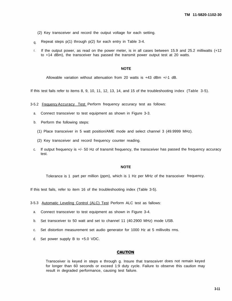
TM 11-5820-1102-30
(2) Key transceiver and record the output voltage for each setting.
q.
r.
Repeat steps p(1) through p(2) for each entry in Table 3-4.
If the output power, as read on the power meter, is in all cases between 15.9 and 25.2 milliwatts (+12to +14 dBm), the transceiver has passed the transmit power output test at 20 watts.
NOTE
Allowable variation without attenuation from 20 watts is +43 dBm +/-1 dB.
test fails refer to items 8, 9, 10, 11, 12, 13, 14, and 15 of the troubleshooting index (Table 3-5).
Frequency Accuracy Test Perform frequency accuracy test as follows:
Connect transceiver to test equipment as shown in Figure 3-3.
Perform the following steps:
If this
3-5.2
a.
b.
(1) Place transceiver in 5 watt position/AME mode and select channel 3 (49.9999 MHz).
(2) Key transceiver and record frequency counter reading.
c. lf output frequency is +/- 50 Hz of transmit frequency, the transceiver has passed the frequency accuracytest.
If this
3-5.3
a.
b.
c.
d.
Tolerance is 1
test fails, refer to
NOTE
part per million (ppm), which is 1 Hz per MHz of the transceiver frequency.
item 16 of the troubleshooting index (Table 3-5).
Automatic Leveling Control (ALC) Test Perform ALC test as fallows:
Connect transceiver to test equipment as shown in Figure 3-4.
Set
Set
Set
transceiver to 50 watt and set to channel 11 (40.2900 MHz) mode USB.
distortion measurement set audio generator for 1000 Hz at 5 millivolts rms.
power supply B to +5.0 VDC.
Transceiver is keyed in steps e through g. Insure that transceiver does not remain keyedfor longer than 60 seconds or exceed 1:9 duty cycle. Failure to observe this caution mayresult in degraded performance, causing test failure.
3-11
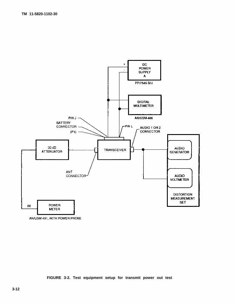
TM 11-5820-1102-30
FIGURE 3-2. Test equipment setup for transmit power out test
3-12

TM 11-5820-1102-30
* FREQUENCY STABILITY MUST BE 0.1 ppm (1 x 10⁻⁷) OR BETTER
FIGURE 3-3. Test equipment setup for frequency accuracy test
3-13
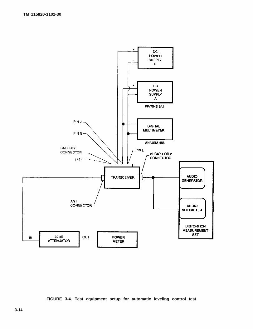
TM 115820-1102-30
FIGURE 3-4. Test equipment setup for automatic leveling control test
3-14

e.
f.
g.
h.
TM 11-5820-1102-30
Key transceiver and verify reading on power meter is between 40 and 63 milliwatts (+16 to +18 dBm).
With transceiver keyed, adjust power supply B to +8 VDC. Verify no power output on power meter.
While transceiver is still keyed, readjust power supply B to +5.0 VDC and verify reading on power meteris between 40 and 63 milliwatts (+16 to +18 dBm).
Unkey transceiver. If transceiver output has no power out at +8 VDC, and power output returns at +5VDC, transceiver has passed the ALC test.
If this test fails, refer to item 17 of the troubleshooting index (Table 3-5).
Section Il. TROUBLESHOOTING PROCEDURE
3-6 TROUBLESHOOTING.
Tests performed during Direct Support maintenance level troubleshooting include:
o Power Ono Frequency Programming and Secure Lightingo Receiveo Transmit
WARNING
Processor board A1 contains a lithium battery. The lithium battery contains flammableorganic materiels. Incorrect handling may cause explosion. DO NOT short battery leadstogether, expose to extreme heat for more than 5-10 seconds, immerse in water or anycleaning solution, make a mistake in polarity, drop, or strike the battery.
WARNING
Circuit card A13 contains BERYLLIUM OXIDE (BeO) CERAMICS. The dust or fumes fromBERYLLIUM OXIDE CERAMICS are HIGHLY TOXIC and breathing them can result in seriouspersonal injury or DEATH. For local guidance/assistance on disposal of unserviceable circuitcard A13, contact your servicing Defense Reutilization and Marketing Office (DRMO).
CAUTION
CAUTION. CONTAINS PARTS AND ASSEMBLIES SUSCEPTIBLE TO DAMAGE BYELECTROSTATIC DISCHARGE (ESD).
3-15

TM 11-5820-1102-30
To troubleshoot the AN/PRC-132 Radio Set, perform the general operation tests to identify the failed test. Then
refer to the troubleshooting index, which lists the replacement sequence for each failed test. Only Direct
Support level repaceable units are listed.
The unit most likely to cause a given failure is listed first, and should be substituted first. If the unit does notcorrect the failure, reinstall original PCB and substitute the next unit on the list. Continue substitution, in theorder listed in the troubleshooting index, until the failure is corrected.
When substitution of a unit corrects failure, assume that the unit is defective and set it aside for repair.After each replacement, recheck the transceiver to ensure that the original failure has not returned.
After completion of this procedure, perform general operational tests before returning the radio set to service.Forward failed unit(s) to the Depot Maintenance facility for repair.
If replacement of all units listed does not solve the problem, forward the entire transceiver or battery box, asapplicable, to depot maintenance for repair.
3-16

TM 11-5820-1102-30
Table 3-5. Troubleshooting Index, RT-1648/PRC-132
NOTE
Refer to paragraph 2-2.5 for removal of Power Amplifier A13. Refer to paragraph 2-2.2 for removal ofInterconnect Board A14. Refer to paragraph 2-2.3 for removal of Control Panel Assembly A22.
Item Indication Probable Trouble Procedure
1 Won’t power up. Power source.
2
Input voltagepresent on pins Jand L of P1, butno current isdrawn.
With PCBsremoved and A22replaced,transceiver stilldoes not powerup.
* Shorted PCBs.
Cannot load Bad A2, oscillator.frequencies intotransceiver, andmanual scan andsecure lightinginoperative.
Bad A1, processor.
Insure 12 VDC is applied between pins J andL on P1. Replace power source. Retest.Refer to Table 3-6 for battery boxtroubleshooting. OBSERVE POLARITY.
NOTE: Insure 12.6 VDC is present betweenP15, pins 4 and 5. If voltage is not present,replace A13. Retest. OBSERVE POLARITY.
Remove all Printed Circuit Boards (PCBs).Replace control panel A22. Apply power andverify Light Emitting Diode (LED) lit andcurrent is drawn.*
Replace A22 and A14. Verify LED lit andcurrent is drawn.*
PWR down. Install PCBs in the followingsequence powering transceiver after eachPCB is installed to insure PCB is not shorted:A1, A2, A3, A7, A8, A9, A10, A11, A12. Ifafter any PCB is installed the transceiver failsto power up, replace the shorted PCB andthe A22. Continue this procedure until allPCBs are installed.
Power down. Remove PCB A2. Installreplacement PCB A2 and power up. Loadfrequencies.
Power down. Remove PCB A1. Installreplacement PCB A1. Power up. Loadfrequencies.
3-17

TM 11-5820-1102-30
Table 3-5. Troubleshooting Index, Transceiver RT-1648/PRC-132 - CONT
Item Indication Probable Trouble Procedure
3 Cannot load Bad A22.frequencies intotransceiver ormanual scan orsecure lightinginoperative.
4
5
Bad A14.
Will not receive. Bad PCB fuse.
Bad A11, filterrelays.
Bad A12, fitterrelays.
Bad A2, LO1.
Bad A3, LO2.
Bad A9, IF mixer.
Bad A8, fitter.
Bad A7, detector.
Bad A22, controlpanel.
Bad A14, wiring.
Low receive audio. Bad A7, detector.
Bad A9, IF mixer.
Power down. Remove Assembly A22. Installreplacement Assembly A22. Power up.Retest.
Power down. Remove PCB A14. Installreplacement PCB A14. Retest.
Visually check each PCB LED for M condition.Power down. Remove affected PCB. Installreplacement PCB. Power up. Check toinsure non-lit condition of PCB LED.
Power down. Remove PCB A11. Installreplacement PCB A11. Power up. Retest.
Power down. Remove PCB A12. Installreplacement PCB A12. Power up. Retest.
Power down. Remove PCB A2. Installreplacement PCB A2. Power up. Retest.
Power down. Remove PCB A3. Installreplacement PCB A3. Power up. Retest.
Power down. Remove PCB A9. Installreplacement PCB A9. Power up. Retest.
Power down. Remove PCB A8. Installreplacement PCB A8. Power up. Retest.
Power down. Remove PCB A7. lnstallreplacement PCB A7. Power up. Retest.
Power down. Remove Assembly A22. Installreplacement Assembly A22. Power up.Retest.
Power down. Remove PCB A14. Installreplacement PCB A14. Power up. Retest.
Power down. Remove PCB A7. Installreplacement PCB A7. Power up. Retest.
Power down. Remove PCB A9. Installreplacement PCB A9. Power up. Retest.
3-18

TM 11-5820-1102-30
Table 3-5. Troubleshooting Index, Transceiver RT-1648/PRC-132 - CONT
Item Indication Probable Trouble Procedure
Bad A8, filter.
Bad A22, controlpanel.
Bad A14, wiring.
6
7
8
Receive sensitivitytest failure.
Failure of audiodistortion test.
Failure of transmitpower out test onall channels withless than 3 ampscurrent drawn.
Bad A9, IF.
Bad A7, detector.
Bad A8, filter.
Bad A22, controlpanel.
Bad A14, wiring.
Bad A2, LO1.
Bad A9, IF.
Bad A7, detector.
Bad A8, filter.
Bad A22, controlpanel.
Bad A14, wiring.
Bad A13, PA.
Power down. Remove PCB A8. Installreplacement PCB A8. Power up. Retest.
Power down. Remove Assembly A22. Installreplacement AssemblyRetest.
Power down. Removereplacement PCB A14.
Power down. Removereplacement PCB A9.
Power down. Removereplacement PCB A7.
Power down. Remove
A22. Power up.
PCB A14. InstallPower up. Retest.
PCB A9. InstallPower up. Retest
PCB A7. InstallPower up. Retest.
PCB A8. Installreplacement PCB A8. Power up. Retest.
Power down. Remove Assembly A22. Installreplacement Assembly A22. Power up.Retest.
Power down. Remove PCB A14. Installreplacement PCB A14. Power up. Retest.
Power down. Remove PCB A2. Installreplacement PCB A2. Power up. Retest.
Power down. Remove PCB A9. Installreplacement PCB A9. Power up. Retest.
Power down. Remove PCB A7. Installreplacement PCB A7. Power up. Retest.
Power down. Remove PCB A8. Installreplacement PCB A8. Power up. Retest.
Power down. Remove Assembly A22. Installreplacement Assembly A22. Power up.Retest.
Power down. Remove PCB A14. Installreplacement PCB A14. Power up. Retest.
Power down. Remove PCB A13. Installreplacement PCB A13. Power up. Retest.
3 - 1 9

TM 11-5820-1102-30
Table 3-5. Troubleshooting Index, Transceiver RT-1648/PRC-132 - CONT
Item Indication Probable Trouble Procedure
9
10
11
12
13
Bad A10, mixer. Power down. Remove PCB A10. Installreplacement PCB A10. Power up. Retest.
Failure of transmit Bad A12, filter Power down, Remove PCB A12. Installpower out test on relay. replacement PCB A12. Power up. Retest.all channels withmore than 17amps drawn.
Bad A11, filterrelay.
Failure of transmit Bad A11, filterpower out test on relay.channels 5, 6, 7,or 8.
Bad A2, LO1.
Failure of transmit Bad A12, filterpower out test on relay.channels 9, 10, or11.
Bad A2, LO1.
Failure of transmit Bad A10, mixer.power out test onall frequencies (lowpower).
Bad A12, filterrelay.
Bad A8, fitter.
Bad A9, 1st IF.
Bad A13, poweramplifier.
Failure of transmit Bad A11, filterpower out test (low relay.power) channels 5,6, 7, or 8.
Power down. Remove PCB A11. Installreplacement PCB A11. Power up. Retest.
Power down. Remove PCB A11. Installreplacement PCB A11. Power up. Retest.
Power down. Remove PCB A2. Installreplacement PCB A2. Power up. Retest.
Power down. Remove PCB A12. Installreplacement PCB A12. Power up. Retest.
Power down. Remove PCB A2. Installreplacement PCB A2. Power up. Retest.
Power down. Remove PCB A10. Installreplacement PCB A10. Power up. Retest.
Power down. Remove PCB A12 Installreplacement PCB A12. Power up. Retest.
Power down. Remove PCB A8. Installreplacement PCB A8. Power up. Retest.
Power down. Remove PCB A9. Installreplacement PCB A9. Power up. Retest.
Power down. Remove PCB A13. Installreplacement PCB A13. Power up. Retest.
Power down. Remove PCB A11. Installreplacement PCB A11. Power up. Retest.
3-20

TM 11-5820-1102-30
Table 3-5. Troubleshooting Index, Transceiver RT-1648/PRC-132 - CONT
Item Indication Probable Trouble Procedure
14
15
16
Bad A13, power Power down. Remove PCB A13. Installamplifier. replacement PCB A13. Power up. Retest.
Failure of transmit Bad A12, fitter Power down. Remove PCB A12. Installpower out test (low relay. replacement PCB A12 Power up. Retest.power) channels 9,10, or 11.
Failure of transmitpower out test(exceeds maximumpower output limit).
Fails frequencyaccuracy testoutput. Frequencyis greater than+/-50 Hz (1 ppm)of the transmitfrequency.
Bad A9, 1st IF.
Bad A8, filter.
Bad A13, poweramplifier.
Bad A12, filterrelay.
Bad A10, mixer.
Bad A22, controlpanel.
Bad A14, wiring.
Bad A2, LO1.
Power down. Remove PCB A9. Installreplacement PCB A9. Power up. Retest.
Power down. Remove PCB A8. Installreplacement PCB A8. Power up. Retest.
Power down. Remove PCB A13. Installreplacement PCB A13. Power up. Retest.
Power down. Remove PCB A12. Installreplacement PCB A12 Power up. Retest.
Power down. Remove PCB A10. Installreplacement PCB A10. Power up. Retest.
Power down. Remove Assembly A22. Installreplacement Assembly A22 Power up.Retest.
Power down. Remove PCB A14. Installreplacement PCB A14. Power up. Retest.
Power down. Remove PCB A2. Installreplacement PCB A2. Power up. Retest.
Bad A3, LO2. Power down. Remove PCB A3. Installreplacement PCB A3. Power up. Retest.
Bad A10, mixer. Power down. Remove PCB A10. Installreplacement PCB A10. Power up. Retest.
3-21

TM 11-5820-1102-30
Table 3-5. Troubleshooting Index, Transceiver RT-1648/PRC-132 - CONT
Item Indication Probable Trouble Procedure
17 Fails Automatic Bad A13. Power down. Remove PCB A13. InstallLeveling Control replacement PCB A13. Power up. Retest.test (ALC). Fullpower out whenpower supply B isadjusted to 8 VDC,or power out doesnot return whenpower supply B isreturned to 5 VDC.
Bad A10.
Bad A22.
Power down. Remove PCB A10. Installreplacement PCB A10. Power up. Retest.
Power down. Remove Assembly A22. lnstalIreplacement Assembly A22. Power up.Retest.
Bad A14. Power down. Remove PCB A14. Installreplacement PCS A14. Power up. Retest.
3 - 2 2
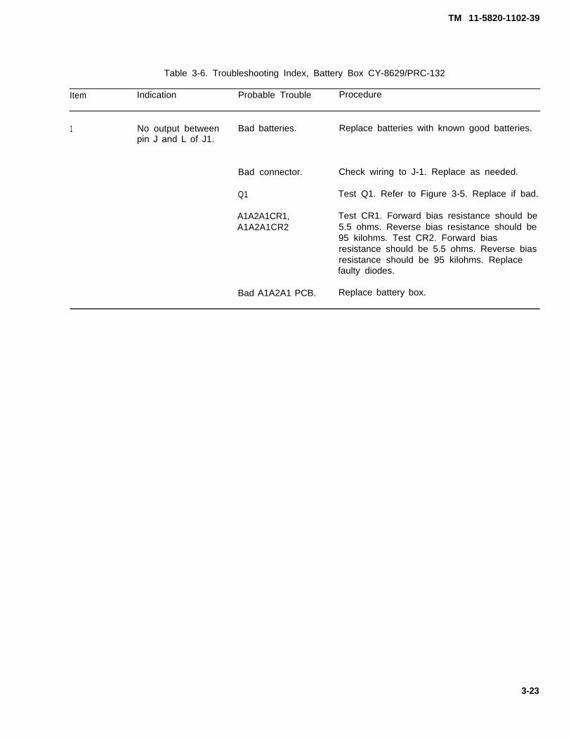
TM 11-5820-1102-39
Table 3-6. Troubleshooting Index, Battery Box CY-8629/PRC-132
Item Indication Probable Trouble Procedure
1 No output between Bad batteries. Replace batteries with known good batteries.pin J and L of J1.
Bad connector. Check wiring to J-1. Replace as needed.
Q1 Test Q1. Refer to Figure 3-5. Replace if bad.
A1A2A1CR1, Test CR1. Forward bias resistance should beA1A2A1CR2 5.5 ohms. Reverse bias resistance should be
95 kilohms. Test CR2. Forward biasresistance should be 5.5 ohms. Reverse biasresistance should be 95 kilohms. Replacefaulty diodes.
Bad A1A2A1 PCB. Replace battery box.
3-23

TM 11-5820-1102-30
Q1, ELECTRICAL
FIGURE 3-5. Q1, graphic and electrical diagrams
3-24

TM 11-5820-1102-30
APPENDIX A - REFERENCES
A-1. SCOPE
This appendix lists all forms, field manuals, technical manuals, and miscellaneous publications referenced inthis manual.
A-2. FORMS
DA Form 2028-2 Recommended Changes to Publications and Blank Forms
SF 361 Transportation Discrepancy Report
SF 364 Report of Discrepancy
SF 368 Quality Deficiency Report
A-3. TECHNICAL MANUALS
TM 11-5820-1102-23P Repair Parts and Special Tools List
TM 11-5820-1102-12 AN/PRC-132 Radio Set Operator’s and Unit Maintenance Manual
TM 750-244-2 Destruction of Army Electronics Materiel to Prevent Enemy Use
A-4. MISCELLANEOUS PUBLICATIONS
DA PAM 738-750 The Army Maintenance Management System (TAMMS)
A-1 (A-2 blank)


TM 11-5820-1102-30
APPENDIX B - EXPENDABLE SUPPLIES AND MATERIELS LIST
Section I. INTRODUCTION
E-1. SCOPE. This appendix lists expendable supplies and materiels you will need to operate and maintainthe AN/PRC-132. This listing is for informational purposes only and is not authority to requisition the listeditems. These items are authorized to you by CTA 50-970, Expendable/Durable Items (except Medical, ClassV, Repair Parts, and Heraldic Items), or CTA 8-100, Army Medical Department Expendable/Durable items.
E2. EXPLANATION OF COLUMNS
a. Column (1) - Item number. This number is assigned to the entry in the listing and is referenced in thenarrative instructions to identify the materiel (Eg., "Use cleaning compound, item 5, app. D").
b. Column (2) - Level. This column identifies the lowest level of maintenance that requires the listed item.
C - Operator/CrewO - Organizational MaintenanceF - Direct Support MaintenanceH - General Support Maintenance
c. Column (3) - National Stock Number. This is the national stock number assigned to the item; use it torequest or requisition the item.
d. Column (4) - Description. Indicates the Federal item name and, if required, a description to identify the
item. The last line for each item indicates the Commercial and Government Entity Code (CAGEC) in
parentheses followed by the part number.
e. Column (5) - Unit of Measure (U/M). Indicates the measure used in performing the actual maintenancefunction. This measure is expressed by a two-character alphabetical abbreviation (eg., ea, in, pr). If theunit of measure differs from the unit of issue, requisition the lowest unit of issue that will satisfy yourrequirements.
B-1

TM 11-5820-1102-30
Section II, Expendable/Durable Supplies and Materiels List
(1) (2) (3) (4) (5)Item NationalNumber Level Stock Description U/M
Number
(Guidance TBS by CECOM)
B - 2

TM 11-5820-1102-30
GLOSSARY
Section I. ABBREVIATIONS
ANT
ACAGCALCAME
BFOBITBWCMOSCWdBDCDMDGECMEMIEPLDEPROMFSKGNDHF/VHFHzIFkHzLCDLEDLOLPI/LPDLSBNFPCBPEPPLLPTT
RFRErmsSINADTCXOT/RUSBVCOVLSIVOGADVrmsVSWR
Alternating CurrentAutomatic Gain ControlAutomatic Level ControlAmplitude Modulation EquivalentAntennaBeat Frequency OscillatorBuilt-In-TestBandwidthComplementary Metal Oxide SemiconductorContinuous WavedecibelsDirect CurrentDigital Message Data GroupElectronic Counter MeasuresElectromagnetic InterferenceErasable Programmable Logic DeviceErasable Programmable Read Only MemoryFrequency Shift KeyGround (electrical)High Frequency/Very High FrequencyHertzIntermediate FrequencyKilo HertzLiquid Crystal DisplayLight Emitting DiodeLocal OscillatorLow Probability of Interrupt/Low Probability of DetectionLower SidebandNoise FactorPrinted Circuit BoardPeak Envelope PowerPhase Locked LoopPush To TalkRandom Access MemoryRadio FrequencyReceiver Exciterroot-mean-squareSignal into Noise and DistortionTemperature Compensated Crystal OscillatorTransmit-ReceiveUpper SidebandVoltage Controlled OscillatorVery Large Scale IntegrationVoice Operated Gain Adjustable DeviceVolts root-mean-squareVoltage Standing Wave Ratio
RAM
G - 1

TM 11-5820-1102-30
Section Il. DEFINITION OF UNUSUAL TERMS
SINAD = Signal Plus Noise Plus Distortion/Noise Plus Distortion
G-2
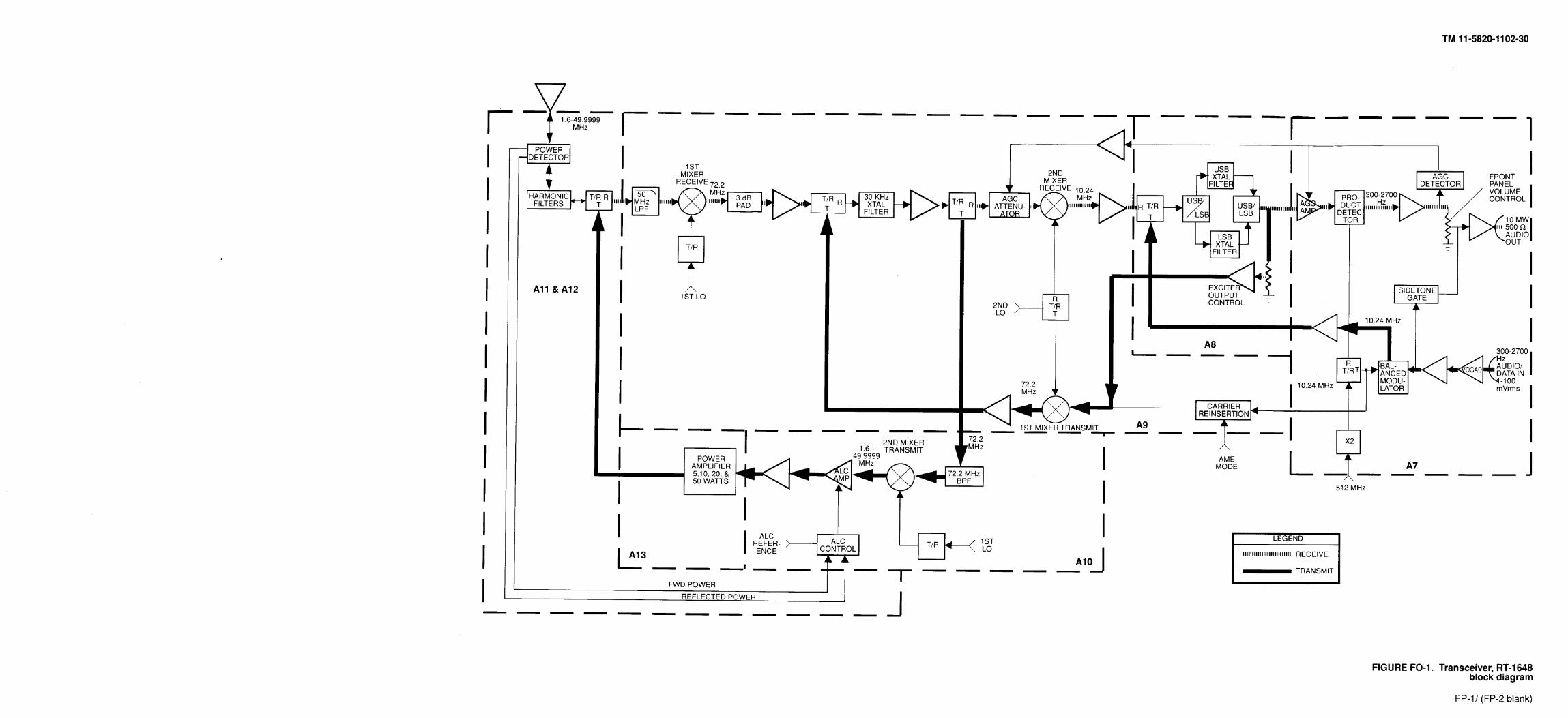
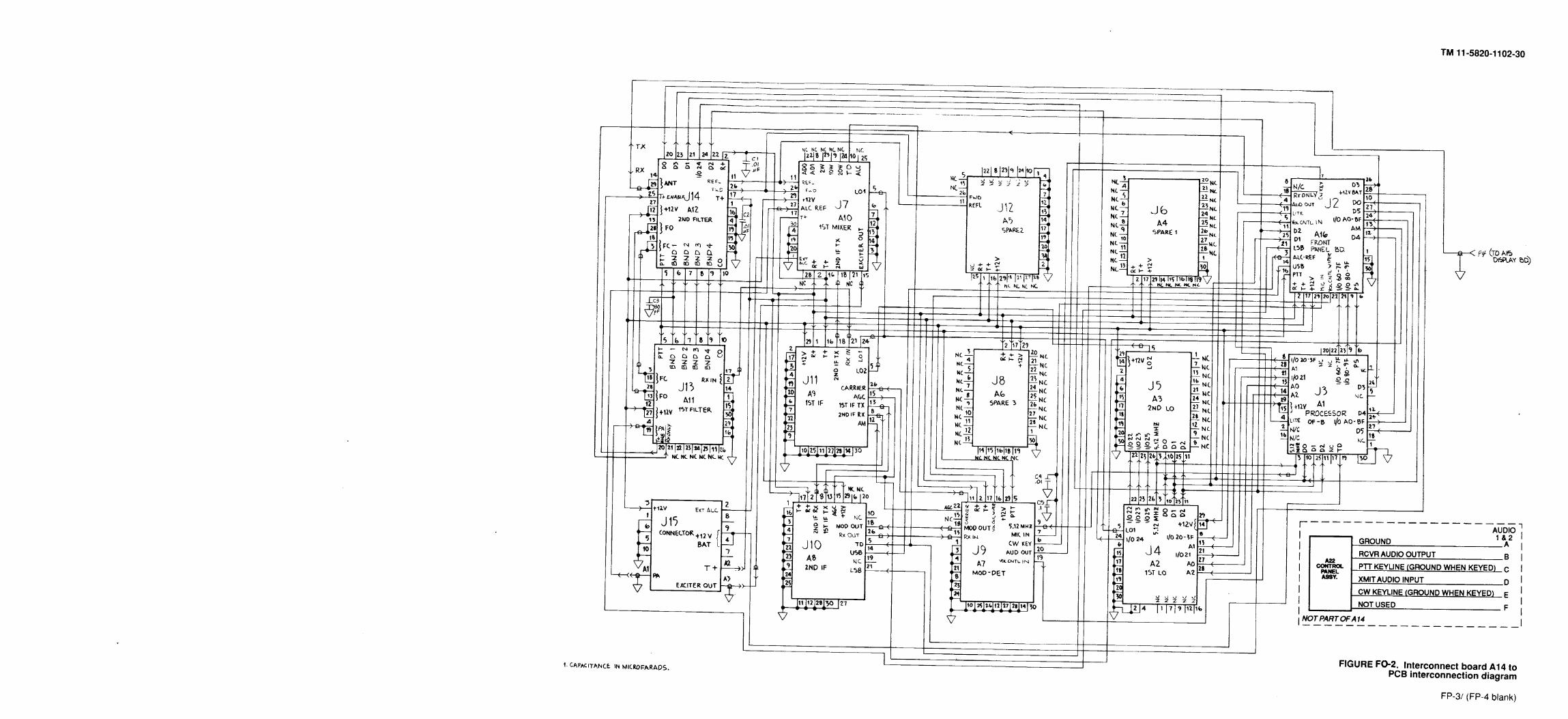

TM 11-5820-1102-30
ALPHABETICAL INDEX
SUBJECT PAGE
A
Battery Box, Disassembly and Assembly
Accuracy, Frequency . . . . . . . . . . . . . . . . . . . . . . . . . . . . . . . . . . . . . . . . . . . . . . . . . . . . ...1-19Army Materiel, Destruction of. . . . . . . . . . . . . . . . . . . . . . . . . . . . . . . . . . . . . . . . . . . . . . ...1-1Assembly and Disassembly. . . . . . . . . . . . . . . . . . . . . . . . . . . . . . . . . . . . . . . . . . . . . . . ...2-1Audio Distortion . . . . . . . . . . . . . . . . . . . . . . . . . . . . . . . . . . . . . . . . . . . . . . . . . . . . . . . ...1-12Audio Distortion Test . . . . . . . . . . . . . . . . . . . . . . . . . . . . . . . . . . . . . . . . . . . . . . . . . . . . ...3-8Audio, Low . . . . . . . . . . . . . . . . . . . . . . . . . . . . . . . . . . . . . . . . . . . . . . . . . . . . . . . . . . ...3-6Automatic Leveling Control (ALC) Test . . . . . . . . . . . . . . . . . . . . . . . . . . . . . . . . . . . . . . . . . ..3-11A1, Processor . . . . . . . . . . . . . . . . . . . . . . . . . . . . . . . . . . . . . . . . . . . . . . . . . . . . . . . . ...1-3A2, 1st LO . . . . . . . . . . . . . . . . . . . . . . . . . . . . . . . . . . . . . . . . . . . . . . . . . . . . . . . . . . . . . .1-3A3, 2nd LO . . . . . . . . . . . . . . . . . . . . . . . . . . . . . . . . . . . . . . . . . . . . . . . . . . . . . . . . . . ...1-3A7, Product Detector . . . . . . . . . . . . . . . . . . . . . . . . . . . . . . . . . . . . . . . . . . . . . . . . . . . . ...1-3A8, 2nd lF . . . . . . . . . . . . . . . . . . . . . . . . . . . . . . . . . . . . . . . . . . . . . . . . . . . . . . . . . . . . . .1-3A9, 1st lF . . . . . . . . . . . . . . . . . . . . . . . . . . . . . . . . . . . . . . . . . . . . . . . . . . . . . . . . . . . . . .1-3A10, 1st Mixer . . . . . . . . . . . . . . . . . . . . . . . . . . . . . . . . . . . . . . . . . . . . . . . . . . . . . . . . ...1-3A11, 1st Filter . . . . . . . . . . . . . . . . . . . . . . . . . . . . . . . . . . . . . . . . . . . . . . . . . . . . . . . . . ..1-3A12, 2nd Filter . . . . . . . . . . . . . . . . . . . . . . . . . . . . . . . . . . . . . . . . . . . . . . . . . . . . . . . . . . .1-3A13, Power Amplifier . . . . . . . . . . . . . . . . . . . . . . . . . . . . . . . . . . . . . . . . . . . . . . . . . . . . . . .1-3A14, Interconnect Board.... . . . . . . . . . . . . . . . . . . . . . . . . . . . . . . . . . . . . . . . . . . . . . ...1-3A15, Display Board . . . . . . . . . . . . . . . . . . . . . . . . . . . . . . . . . . . . . . . . . . . . . . . . . . . . . . . .1-3A16, Front Panel Board . . . . . . . . . . . . . . . . . . . . . . . . . . . . . . . . . . . . . . . . . . . . . . . . . . . . .1-3A22, Front Panel Assembly . . . . . . . . . . . . . . . . . . . . . . . . . . . . . . . . . . . . . . . . . . . . . . . . . .1-5
Card Cage Removal and Assembly .Care and Handling, Safety . . . . . . .Carrier Suppression . .Channels
Scanning . . . . . .Setting . . . . . . . .
Channels 1-11, Loading
. . . . . . . . .
. . . . . . . . .
. . . . . . . . .Frequencies
. . . .
. . . .
. . . .
. . . .
. . . .
. . . .Characteristics, Capabilities, and Features,Circuitry
Control andlnterface . . . . . .Power Supply and DistributionReceive Path . . . . . . . . . . . .Synthesizer . . . . . . . . . . . . .Transmit Path . . . . . . . . . . .
. . . . .
. . . . .
. . . . .
. . . . .
. . . . .Common Tools, Special Tools, TMDE, and
B
. . . . . . . . . . . . . . . . . . . . . . . . . . . . . . . . . . . . .
C
. . . . . . . .
. . . . . . . .
. . . . . . . .
. . . . . . . .
. . . . . . . .
. . . . . . . .Equipment
. . . . . .
. . . . . .
.. . . ..
. . . . . .
. . . . . .Support
. .
. .
. .
. .
. .
. . . . . . . . . . . . . . . . . . . . . . . . . . . . .
. . . . . . . . . . . . . . . . . . . . . . . . . . ...
. . . . . . . . . . . . . . . . . . . . . . . . ... .
. . . . . . . . . . . . . . . . . . . . . . . . . ... . . .
. . . . . . . . . . . . . . . . . . . . . . . . . . . . . . . .
. . . . . . . . . . . . . . . . . . . . . . . . . . . . . . .
. . . . . . . . . . . . . . . . . . . . . . .. . . . . .
. . . . . . . . . . . . . . . . . . . . . . . . . . . . . . . .
. . . . . . . . . . . . . . . . . . . . . . . . . . . . . . . .
. . . . . . . . . . . . . . . . . . . . . . . . . . . . . . . .
. . . . . . . . . . . . . . . . . . . . . . . . . . . . . . . .
. . . . . . . . . . . . . . . . . . . . . . . . . . . . . . .. Equipment . . . . . . . . . . . . . . . . . . . . . . . . . .
2-6
2-21-51-16
3-43-23-21-2
1-201-191-61-171-122-1
I - 1
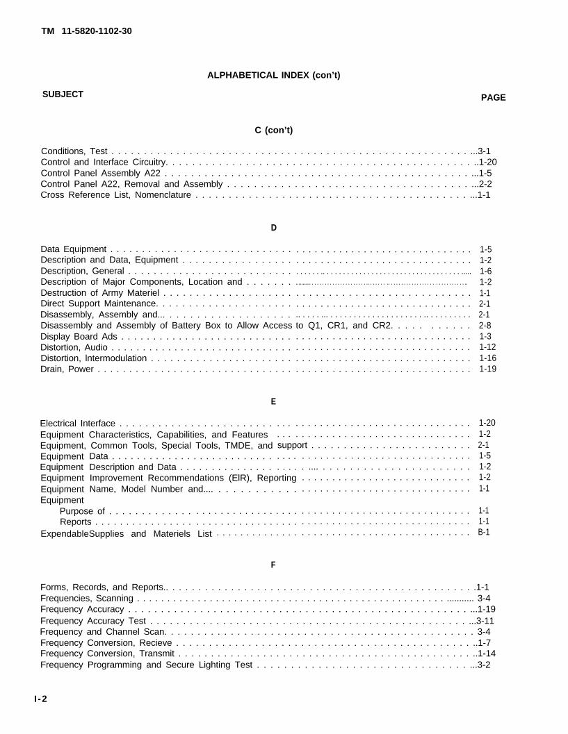
TM 11-5820-1102-30
ALPHABETICAL INDEX (con’t)
SUBJECT PAGE
C (con’t)
Conditions, Test . . . . . . . . . . . . . . . . . . . . . . . . . . . . . . . . . . . . . . . . . . . . . . . . . . . . . . . ...3-1Control and Interface Circuitry. . . . . . . . . . . . . . . . . . . . . . . . . . . . . . . . . . . . . . . . . . . . . . ..1-20Control Panel Assembly A22 . . . . . . . . . . . . . . . . . . . . . . . . . . . . . . . . . . . . . . . . . . . . . . ...1-5Control Panel A22, Removal and Assembly . . . . . . . . . . . . . . . . . . . . . . . . . . . . . . . . . . . . ...2-2Cross Reference List, Nomenclature . . . . . . . . . . . . . . . . . . . . . . . . . . . . . . . . . . . . . . . . . ...1-1
D
Data Equipment . . . . . . . . . . . . . . . . . . . . . . . . . . . . .Description and Data, Equipment . . . . . . . . . . . . . . . . .Description, General . . . . . . . . . . . . . . . . . . . . . . . . . .Description of Major Components, Location and . . . . . . .Destruction of Army Materiel . . . . . . . . . . . . . . . . . . . .Direct Support Maintenance. . . . . . . . . . . . . . . . . . . . .Disassembly, Assembly and... . . . . . . . . . . . . . . . . . .Disassembly and Assembly of Battery Box to Allow AccessDisplay Board Ads . . . . . . . . . . . . . . . . . . . . . . . . . . .Distortion, Audio . . . . . . . . . . . . . . . . . . . . . . . . . . . . .Distortion, lntermodulation . . . . . . . . . . . . . . . . . . . . . .Drain, Power . . . . . . . . . . . . . . . . . . . . . . . . . . . . . . .
E
Electrical Interface . . . . . . . . . . . . . . . . . . . . . . . .Equipment Characteristics, Capabilities, and FeaturesEquipment, Common Tools, Special Tools, TMDE, andEquipmentEquipmentEquipmentEquipmentEquipment
Data . . . . . . . . . . . . . . . . . . . . . . . . . .Description and Data . . . . . . . . . . . . . . .
. . .
. . .
. . . . . . . . . . . . . . . . . . . . . . . . . . . . .
. . . . . . . . . . . . . . . . . . . . . . . . . . . . .
. . . . . . .. . . . . . . . . . . . . . . . . . . . . . . . . . . . . . . . . . .....
........... . . . . . . . . . . . . . . . . . . . . . .. . . . . . . .. . . . . . . . . . . . . . . . . . . . . . . . . . . . . ..
. . . . . . . . . . . . . . . . . . . . . . . . . . .
. . . . . . . . . . . . . . . . . . . . . . . . . . . . .
.. . . . . ... . . . . . . . . . . . . . . . . . . . . .. . . . . . . . . .to Q1, CR1, and CR2. . . . . . . . . . .. . . . . . . . . . . . . . . . . . . . . . . . . . . . .. . . . . . . . . . . . . . . . . . . . . . . . . . . . .. . . . . . . . . . . . . . . . . . . . . . . . . . . . .. . . . . . . . . . . . . . . . . . . . . . . . . . . . .
support . . . . . . . . . . . . . . . . . . . . . . . . .
Purpose of . . . . . . . . . . . . .Reports . . . . . . . . . . . . . . . .
ExpendableSupplies and Materiels List
. . . . . . . . . . . . . . . . . . . . . . . . . . . . .
. . . . . . . . . . . . . . . . . . . . . . . . . . . . .
. . . .
. . . .Improvement Recommendations (ElR), ReportingName, Model Number and.... . . . . . . . . . . .
. . . . . . . . . . . . . . . . .
. . . . . . . . . . . . . . . . . . . . . . . . . . . . . . .
F
. . . . . . . . . . . . . . . . . . . . . . . . . . . .
. .... . . . . . . . . . . . . . . . . . . . . . .
. . . . . . . . . . . . . . . . . . . . . . . . . . . .
. . . . . . . . . . . . . . . . . . . . . . . . . . . .
. . . . . . . . . . . . . . . . . . . . . . . . . . . .
. . . . . . . . . . . . . . . . . . . . . . . . . . . .
. . . . . . . . . . . . . . . . . . . . . . . . . . . .
1-51-21-61-21-12-12-12-81-31-121-161-19
1-201-22-11-51-21-21-1
1-11-1B-1
Forms, Records, and Reports.. . . . . . . . . . . . . . . . . . . . . . . . . . . . . . . . . . . . . . . . . . . . . . . .1-1Frequencies, Scanning . . . . . . . . . . . . . . . . . . . . . . . . . . . . . . . . . . . . . . . . . . . . . . . . . . . ........... 3-4Frequency Accuracy . . . . . . . . . . . . . . . . . . . . . . . . . . . . . . . . . . . . . . . . . . . . . . . . . . . . ...1-19Frequency Accuracy Test . . . . . . . . . . . . . . . . . . . . . . . . . . . . . . . . . . . . . . . . . . . . . . . . ...3-11Frequency and Channel Scan. . . . . . . . . . . . . . . . . . . . . . . . . . . . . . . . . . . . . . . . . . . . . . . 3-4Frequency Conversion, Recieve . . . . . . . . . . . . . . . . . . . . . . . . . . . . . . . . . . . . . . . . . . . . . ..1-7Frequency Conversion, Transmit . . . . . . . . . . . . . . . . . . . . . . . . . . . . . . . . . . . . . . . . . . . . . ..1-14Frequency Programming and Secure Lighting Test . . . . . . . . . . . . . . . . . . . . . . . . . . . . . . . ...3-2
I -2
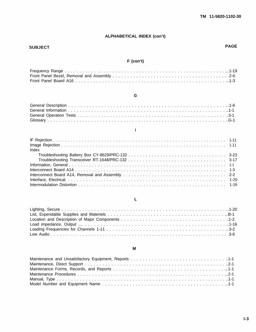
TM 11-5820-1102-30
ALPHABETICAL INDEX (con’t)
SUBJECT PAGE
F (con’t)
Frequency Range . . . . . . . . . . . . . . . . . . . . . . . . . . . . . . . . . . . . . . . . . . . . . . . . . . . . . . ...1-19Front Panel Bezel, Removal and Assembly . . . . . . . . . . . . . . . . . . . . . . . . . . . . . . . . . . . . . . . .2-6Front Panel Board A16 . . . . . . . . . . . . . . . . . . . . . . . . . . . . . . . . . . . . . . . . . . . . . . . . . . ...1-3
G
General Description . . . . . . . . . . . . . . . . . . . . . . . . . . . . . . . . . . . . . . . . . . . . . . . . . . . . ...1-6General Information . . . . . . . . . . . . . . . . . . . . . . . . . . . . . . . . . . . . . . . . . . . . . . . . . . . . . . ..1-1General Operation Tests . . . . . . . . . . . . . . . . . . . . . . . . . . . . . . . . . . . . . . . . . . . . . . . . . . ..3-1Glossary . . . . . . . . . . . . . . . . . . . . . . . . . . . . . . . . . . . . . . . . . . . . . . . . . . . . . . . . . . . . . ..G-1
I
lF Rejection . . . . . . . . . . . . . . . . . . . . . . . . . . . . . . . . . . . . . . . . . . . . . . . . . . . . . . . . . . . . .Image Rejection . . . . . . . . . . . . . . . . . . . . . . . . . . . . . . . . . . . . . . . . . . . . . . . . . . . . . . . . . .Index
Troubleshooting Battery Box CY-8629/PRC-132 . . . . . . . . . . . . . . . . . . . . . . . . . . . . . . . . . .Troubleshooting Transceiver RT-1648/PRC-132 . . . . . . . . . . . . . . . . . . . . . . . . . . . . . . . . . .
Information, General . . . . . . . . . . . . . . . . . . . . . . . . . . . . . . . . . . . . . . . . . . . . . . . . . . . . . . .lnterconnect Board A14 . . . . . . . . . . . . . . . . . . . . . . . . . . . . . . . . . . . . . . . . . . . . . . . . . . . . .Interconnect Board A14, Removal and Assembly . . . . . . . . . . . . . . . . . . . . . . . . . . . . . . . . . . . .Interface, Electrical. . . . . . . . . . . . . . . . . . . . . . . . . . . . . . . . . . . . . . . . . . . . . . . . . . . . . .lntermodulation Distortion . . . . . . . . . . . . . . . . . . . . . . . . . . . . . . . . . . . . . . . . . . . . . . . . . . . .
1-111-11
3-233-171-11-32-21-201-16
L
Lighting, Secure . . . . . . . . . . . . . . . . . . . . . . . . . . . . . . . . . . . . . . . . . . . . . . . . . . . . . . . ...1-20List, Expendable Supplies and Materiels . . . . . . . . . . . . . . . . . . . . . . . . . . . . . . . . . . . . . . ...B-1Location and Description of Major Components . . . . . . . . . . . . . . . . . . . . . . . . . . . . . . . . . . ..1-2Load impedance, Output .... . . . . . . . . . . . . . . . . . . . . . . . . . . . . . . . . . . . . . . . . . . . . . ..1-16Loading Frequencies for Channels 1-11 . . . . . . . . . . . . . . . . . . . . . . . . . . . . . . . . . . . . . . . ...3-2Low Audio . . . . . . . . . . . . . . . . . . . . . . . . . . . . . . . . . . . . . . . . . . . . . . . . . . . . . . . . . . . . . .3-6
M
Maintenance and Unsatisfactory Equipment, Reports . . . . . . . . . . . . . . . . . . . . . . . . . . . . . . . ..1-1Maintenance, Direct Support . . . . . . . . . . . . . . . . . . . . . . . . . . . . . . . . . . . . . . . . . . . . . . . ..2-1Maintenance Forms, Records, and Reports . . . . . . . . . . . . . . . . . . . . . . . . . . . . . . . . . . . . ...1-1Maintenance Procedures . . . . . . . . . . . . . . . . . . . . . . . . . . . . . . . . . . . . . . . . . . . . . . . . . ...2-1Manual, Type . . . . . . . . . . . . . . . . . . . . . . . . . . . . . . . . . . . . . . . . . . . . . . . . . . . . . . . . . . ..1-1Model Number and Equipment Name . . . . . . . . . . . . . . . . . . . . . . . . . . . . . . . . . . . . . . . . ...1-1
I-3

TM 11-5820-1102-30
ALPHABETICAL INDEX (con’t)
SUBJECT PAGE
N
No RX . . . . . . . . . . . . . . . . . . . . . . . . . . . . . . . . . . . . . . . . . . . . . . . . . . . . . . . . . . . . . ...3-6Nomenclature Cross Reference List . . . . . . . . . . . . . . . . . . . . . . . . . . . . . . . . . . . . . . . . . . ...1-1
0
Output Power, Rf . . . . . . . . . . . . . . . . . . . . . . . . . . . . . . . . . . . . . . . . . . . . . . . . . . . . . . ...1-16Operation, Principles of...... . . . . . . . . . . . . . . . . . . . . . . . . . . . . . . . . . . . . . . . . . . . . . . .1-6Opposite Sideband Suppression . . . . . . . . . . . . . . . . . . . . . . . . . . . . . . . . . . . . . . . . . . . . . . .1-16Output Load Impedance . . . . . . . . . . . . . . . . . . . . . . . . . . . . . . . . . . . . . . . . . . . . . . . . . . . .1-16
P
Packaging and Handling Deficiencies, Report . . . . . . . . . . . . . . . . . . . . . . . . . . . . . . . . . . . ...1-1Parts and Special Tools, Repair . . . . . . . . . . . . . . . . . . . . . . . . . . . . . . . . . . . . . . . . . . . . . ..2-1Power Amplifier A13 . . . . . . . . . . . . . . . . . . . . . . . . . . . . . . . . . . . . . . . . . . . . . . . . . . . . ...1-3Power Amplifier A13, Removal and Assembly . . . . . . . . . . . . . . . . . . . . . . . . . . . . . . . . . . . . . . 2-6Power Drain . . . . . . . . . . . . . . . . . . . . . . . . . . . . . . . . . . . . . . . . . . . . . . . . . . . . . . . . . . ...1-19Power On Test . . . . . . . . . . . . . . . . . . . . . . . . . . . . . . . . . . . . . . . . . . . . . . . . . . . . . . . . ...3-1Power Supply and Distribution Circuitry . . . . . . . . . . . . . . . . . . . . . . . . . . . . . . . . . . . . . . . ...1-19Principles of Operation . . . . . . . . . . . . . . . . . . . . . . . . . . . . . . . . . . . . . . . . . . . . . . . . . . ...1-6Procedure, Troubleshooting . . . . . . . . . . . . . . . . . . . . . . . . . . . . . . . . . . . . . . . . . . . . . . . . . .3-15Procedures, Maintenance . . . . . . . . . . . . . . . . . . . . . . . . . . . . . . . . . . . . . . . . . . . . . . . . . . . .2-1Processor A1 . . . . . . . . . . . . . . . . . . . . . . . . . . . . . . . . . . . . . . . . . . . . . . . . . . . . . . . . . ...1-3Product Detector A7 . . . . . . . . . . . . . . . . . . . . . . . . . . . . . . . . . . . . . . . . . . . . . . . . . . . . ...1-3Protection, Reverse Voltage . . . . . . . . . . . . . . . . . . . . . . . . . . . . . . . . . . . . . . . . . . . . . . . ...1-19Purpose of Equipment . . . . . . . . . . . . . . . . . . . . . . . . . . . . . . . . . . . . . . . . . . . . . . . . . . . . . .1-1
R
Range, Frequency . . . . . . . . . . . . . . . . . . . . . . . . . . . . . . . . . . . . . . . . . . . . . . . . . . . . . . . .Ratio, Voltage Standing Wave (VSWR) . . . . . . . . . . . . . . . . . . . . . . . . . . . . . . . . . . . . . . . . . . .Receive Frequency Conversion . . . . . . . . . . . . . . . . . . . . . . . . . . . . . . . . . . . . . . . . . . . . . . . .Receive Path Circuitry . . . . . . . . . . . . . . . . . . . . . . . . . . . . . . . . . . . . . . . . . . . . . . . . . . . . . .Reciever Selectivity . . . . . . . . . . . . . . . . . . . . . . . . . . . . . . . . . . . . . . . . . . . . . . . . . . . . . . . .Receiver Sensitivity... . . . . . . . . . . . . . . . . . . . . . . . . . . . . . . . . . . . . . . . . . . . . . . . . . . . . .Receiver Tests . . . . . . . . . . . . . . . . . . . . . . . . . . . . . . . . . . . . . . . . . . . . . . . . . . . . . . . . . . .References . . . . . . . . . . . . . . . . . . . . . . . . . . . . . . . . . . . . . . . . . . . . . . . . . . . . . . . . . . . . .Rejection, lF . . . . . . . . . . . . . . . . . . . . . . . . . . . . . . . . . . . . . . . . . . . . . . . . . . . . . . . . . . . .Rejection, image . . . . . . . . . . . . . . . . . . . . . . . . . . . . . . . . . . . . . . . . . . . . . . . . . . . . . . . . . .Removal and Assembly
Card Cage . . . . . . . . . . . . . . . . . . . . . . . . . . . . . . . . . . . . . . . . . . . . . . . . . . . . . . . . . .Control Panel A22 . . . . . . . . . . . . . . . . . . . . . . . . . . . . . . . . . . . . . . . . . . . . . . . . . . .Front Panel Bezel . . . . . . . . . . . . . . . . . . . . . . . . . . . . . . . . . . . . . . . . . . . . . . . . . . . . . .interconnect Board A14 . . . . . . . . . . . . . . . . . . . . . . . . . . . . . . . . . . . . . . . . . . . . . . . . . .Power Amplifier A13 . . . . . . . . . . . . . . . . . . . . . . . . . . . . . . . . . . . . . . . . . . . . . . . . . . . .
1-191-171 - 71 - 61-101-103 - 6A - 11-111-11
2-22-22-62-22-6
I -4
TM 11-5820-1102-30
ALPHABETICAL INDEX (con’t)
S U B J E C T PAGE
R (con't)
Repair . . . . . . . . . . . . . . . . . . . . . . . . . . . . . . . . . . . . . . . . .Repair Parts and Special Tools. . . . . . . . . . . . . . . . . . . . . . . .Reports of Maintenance and Unsatisfactory Equipment . . . . . . .Report of Packing and Handling Deficiencies . . . . . . . . . . . .Report, Transportation Discrepancy. . . . . . . . . . . . . . . . . . . . .Reporting Equipment Improvement Recommendations (EIR) . . . .
2-82-11-11-11-11-21-191-163-6
. . . . . . . . . . . . . . . .
. . . . . . . . . . . . . . . .
. . . . . . . . . . . . . . . .
. . . . . . . . . . . . . . . .
. . . . . . . . . . . . . . . .
. . . . . . . . . . . . . . . .
. . . . . . . . . . . . . . . .
. . . . . . . . . . . . . . . .
. . . . . . . . . . . . . . . .
. . . . . .
. . . . . .. .. .. .. .. .. .. .. .. .
. .
. .
. .
. .
. .
. .
. .
. .
. .
. .
. .
. .
. .
. .
. .
. .
. .
. .
. .
. . .
. . .
. . .
. . .
. . .
. . .
. . .
. . .
. . .
. . .
. . .
. . .
. . .
. . .
. . .
. . .
. . .
. . .
. . .
. . .
. . .
. . .
. . .
. . .
. . .
. . .
. . .
. . .
. . .
. . .
. . .
. . .
. . .
. . .
. . .
. . .
. . .
. . .
. . .
. . .
. . .
. . .
. . .
. . .
. . .
. . .
. . .
. . .
. . .
. . .
. . .
. . .
Reverse Voltage Protection . .RF Output Power . . . . . . . . .RX, No . . . . . . . . . . . . . . . .
. . .
. . .
. . .
. . .
. . .
. . .
. . .
. . .
. . .
. . .
. . .
. . .
. . .
. . .
. . .
. . .
. . .
. . .
. . .
. . .
. . .
. . .
. . .
. . .
. . .
. . .
. . .
. . .
. . .
. . .
. . .
. . .
. . .
. . .
. . .
.
.
.
.
.
.
.
.
.
.
.
.
.
.
.
.
.
.
.
.
.
.
.
.
.
.
. . . . . .
. . . . . .
. . . . . .
. . . . . . . . . . .
. . . . . . . . . . .
. . . . . . . . . . .
S
Safety, Care, and Handling . .Scan, Frequency and ChannelScanning Channels . . . . . . . .Scanning Frequencies . . . . . .scope . . . . . . . . . . . . . . . . .Secure Lighting . . . . . . . . . .Secure Lighting Test . . . . . . .Selectivity, Receiver . . . . . . .Sensitivity, Receiver . . . . . . .Sensitivity Test . . . . . . . . . . .Setting Channels . . . . . . . . .Spare Card Slots . . . . . . . . .
1-53-43-43-41-11-203-51-101-103 -63 -21-51-161-161-17
. . . . . .
. . . . . .
. . . . . .
. . . . . .
. . . . . .
. . . . . .
. . . . . .
. . . . . .
. . . . . .
. . . . . .
. . . . . .
. . . . . .
. . . . . .
. . . . . .
. . . . . .
. . . . . . . . . . .
. . . . . . . . . . .
. . . . . . . . . . .
. . . . . . . . . . .
. . . . . . . . . . .
. . . . . . . . . . .
. . . . . . . . . . .
. . . . . . . . . . .
. . . . . . . . . . .
. . . . . . . . . . .
. . . . . . . . . . .
. . . . . . . . . . .
. . . . . . . . . . .
. . . . . . . . . . .
. . . . . . . . . . .
. . . . . . . . . . . . . . . .
. . . . . . . . . . . . . . . .
. . . . . . . . . . . . . . . .
. . . . . . . . . . . . . . . .
. . . . . . . . . . . . . . . .
. . . . . . . . . . . . . . . .
. . . . . . . . . . . . . . . .
. . . . . . . . . . . . . . . .
. . . . . . . . . . . . . . . .
. . . . . . . . . . . . . . . .
. . . . . . . . . . . . . . . .
. . . . . . . . . . . . . . . .
. . . . . . . . . . . . . . . .
. . . . . . . . . . . . . . . .
. . . . . . . . . . . . . . . .
Sideband Suppression, Opposite .Suppression, Cagier . . . . . . . . . .Synthesizer Circuitry . . . . . . . . . .
T. . . . . . . . . . .Test Condition . . . . . . . . . . . . .
TestAudio Distortion . . . . . . . . . .
3-1. . . . . . . . . . . . . . . . . . . . . .
3-83-113-113-13-53-63-93-2
. . . . . .
. . . . . .. . . . . . . . . . .. . . . . . . . . . .. . . . . . . . . . .. . . . . . . . . . .
. . . . . . . . . . . . . . . .
. . . . . . . . . . . . . . . .
. . . . . . . . . . . . . . . .
. . . . . . . . . . . . . . . .
Automatic Leveling Control (ALC) .Frequency Accuracy . . . . . .Power On . . . . . . . . . . . . .Secure Lighting . . . . . . . . .Sensitivity.......................Transmit Power Out . . . . . .Frequency Programming and
TestsGeneral Operation . . . . . . .Reliever . . . . . . . . . . . . . .Transmit . . . . . . . . . . . . . .
Transmit Frequency Conversion .Transmit Path Circuitry . . . . . . .
. . . .
. . . .
. . . .
. . . .
. . . .
. . . . . .
. . . . . .
. . . . . .. . . . . . . .. . . . . . . .. . . . . . . .. . . . . . . .. . . . . . . .
. . . . . . . . . . . . . . . . . . . . . . . . . . .
. . . . . . . . . . . . . . . . . . . . . . . . . . .
. . . . . . . . . . . . . . . . . . . . . . . . . . .. . . . . . . . . . . . . . . . . . . . . . . . . .
. . . . . .
. . . . . .Secure Lighting
3-13-63-81-141-121-1
. . . . .
. . . . .
. . . . .
. . . . .
. . . . .
. . . . . . . . . . . . . . . . . . . . . . . . . . . . . . . . .. . . . . . . . . . . . . . . . . . . . . . . . . . .. . . . . . . . . . . . . . . . . . . . . . . . . . .. . . . . . . . . . . . . . . . . . . . . . . . . . .. . . . . . . . . . . . . . . . . . . . . . . . . . .. . . . . . . . . . . . . . . . . . . . . . . . . . .
. . . . . . . .
. . . . . . . .
. . . . . . . .
. . . . . . . .
. . . . . . . .
. . . . . . . .
. . . . . .
. . . . . .
. . . . . .
. . . . . .(SF361)Transportation Discrepancy Report (TDR)
I-5

TM 11-5820-1102-30
ALPHABETICAL INDEX (con’t)
SUBJECT PAGE
T (con’t)
Troubleshooting . . . . . . . . . . . . . . . . . . . . . . . . . . . . . . . . . . . . . . . . . . . . . . . . . . . . . . . ...3-1Troubleshooting Index
Battery Box CY-8629/PCR-132... . . . . . . . . . . . . . . . . . . . . . . . . . . . . . . . . . . . . . . . ...3-23Transceiver RT-1648/PRC-132... . . . . . . . . . . . . . . . . . . . . . . . . . . . . . . . . . . . . . . . ...3-17
Troubleshooting Procedure . . . . . . . . . . . . . . . . . . . . . . . . . . . . . . . . . . . . . . . . . . . . . . . ...3-15Type of Manual . . . . . . . . . . . . . . . . . . . . . . . . . . . . . . . . . . . . . . . . . . . . . . . . . . . . . . . ...1-1
U
Unsatisfactory Equipment, Reports . . . . . . . . . . . . . . . . . . . . . . . . . . . . . . . . . . . . . . . . . . ...1-1
1st1st1st1st
V
Standing Wave Ratio (VSWR) . . . . . . . . . . . . . . . . . . . . . . . . . . . . . . . . . . . . . . . . ...1-17
1
FilterA11 . . . . . . . . . . . . . . . . . . . . . . . . . . . . . . . . . . . . . . . . . . . . . . . . . . . . . . . . ...1-3IF, A9 . . . . . . . . . . . . . . . . . . . . . . . . . . . . . . . . . . . . . . . . . . . . . . . . . . . . . . . . . . . ...1-3LO AD . . . . . . . . . . . . . . . . . . . . . . . . . . . . . . . . . . . . . . . . . . . . . . . . . . . . . . . . . . . ...1-3Mixer A10 . . . . . . . . . . . . . . . . . . . . . . . . . . . . . . . . . . . . . . . . . . . . . . . . . . . . . . . . . ...1-3
2
2nd Filter A12 . . . . . . . . . . . . . . . . . . . . . . . . . . . . . . . . . . . . . ................1-32nd lF A8 . . . . . . . . . . . . . . . . . . . . . . . . . . . . . . . . . . . . . . . . . . . . . . . . . . . . . . . ......1-32nd LO A3 . . . . . . . . . . . . . . . . . . . . . . . . . . . . . . . . . . . . . . . ................1-3
I - 6


By Order of the Secretary of the Army:
GORDON R. SULLIVANGeneral, United States Army
Chief of Staff
Official:
MILTON H. HAMILTONAdministrative Assistant to the
Secretary of the Army01282
DISTRIBUTION:
To be distributed in accordance with DA Form 12-36–E,block 9097, Direct and General Support Maintenancerequirements for TM 11–5820-1102–30.
*U.S. GOVERNMENT PRINTING OFFICE: 1992 - 612-084/60167


Related Documents