UNION RADIO-SCIENTIFIQUE INTERNATIONALE INTERNATIONAL UNION OF RADIO SCIENCE ISSN 1024-4530 URSI, c/o Ghent University (INTEC) St.-Pietersnieuwstraat 41, B-9000 Gent (Belgium) No 356 March 2016 Radio Science Bulletin

Welcome message from author
This document is posted to help you gain knowledge. Please leave a comment to let me know what you think about it! Share it to your friends and learn new things together.
Transcript
UNIONRADIO-SCIENTIFIQUE
INTERNATIONALE
INTERNATIONALUNION OF
RADIO SCIENCE
ISSN
102
4-45
30
URSI, c/o Ghent University (INTEC)St.-Pietersnieuwstraat 41, B-9000 Gent (Belgium)
No 356March 2016R
adio
Sci
ence
Bul
letin
2 The Radio Science Bulletin No 356 (March 2016)
Front cover: “The geometry of a two-level quantum switching system using an electron manipulated by a tailored light-pulse pair”. See the paper by Takashi Takeuchi, Shinichiro Ohnuki, and Tokuei Sako, pp. 13-19.
ContentsRadio Science Bulletin Staff ....................................................................................... 3URSI Offi cers and Secretariat ................................................................................... 6Editor’s Comments ..................................................................................................... 8Presidents Newsletter ................................................................................................ 10Introduction to the Special Section on URSI-JRSM 2015
Student Paper Competition .................................................................................. 11A Quantum Switching System Manipulated by a Light Pulse Pair
Designed in a Maxwell-Schrödinger Hybrid Algorithm .................................... 13Terahertz Wireless Transmission Enabled by Photonics Using Binary
Phase-Shift Keying at 300 GHz .......................................................................... 20Large-Scale Subsurface Velocity Estimation with YAKUMO
GPR Array System ............................................................................................... 24Flat Transparent Antennas....................................................................................... 32URSI 2017 GASS....................................................................................................... 41Awards for Young Scientists - Conditions ............................................................... 42Ethically Speaking .................................................................................................... 43Historical Column ..................................................................................................... 45XXst International Seminar/Workshop: Direct and Inverse Problems of
Electromagnetic and Acoustic Wave Theory (DIPED-2016) ............................ 48Telecommunications Health and Safety .................................................................. 4916th International Conference on Mathematical Methods in Electromagnetic
Theory .................................................................................................................... 52Women in Radio Science .......................................................................................... 53French National Committee Elects Commission Offi cers ..................................... 55URSI Accounts .......................................................................................................... 56Report on the 33rd National Radio Science Conference (NRSC 2016) ............... 60Report on 2015 Spanish URSI Symposium ............................................................ 64URSI Conference Calendar ...................................................................................... 66Information for Authors ........................................................................................... 68
The International Union of Radio Science (URSI) is a foundation Union (1919) of the International Council of Scientifi c Unions as direct and immediate successor of the Commission Internationale de Télégraphie Sans Fil which dates from 1914.Unless marked otherwise, all material in this issue is under copyright © 2016 by Radio Science Press, Belgium, acting as agent and trustee for the International Union of Radio Science (URSI). All rights reserved. Radio science researchers and instructors are permitted to copy, for non-commercial use without fee and with credit to the source, material covered by such (URSI) copyright. Permission to use author-copyrighted material must be obtained from the authors concerned.The articles published in the Radio Science Bulletin refl ect the authors’ opinions and are published as presented. Their inclusion in this publication does not necessarily constitute endorsement by the publisher. Neither URSI, nor Radio Science Press, nor its contributors accept liability for errors or consequential damages.
The Radio Science Bulletin No 356 (March 2016) 3
Radio Science Bulletin StaffEditor
W. R. StoneStoneware Limited840 Armada TerraceSan Diego, CA 92106, USATel: +1-619 222 1915, Fax: +1-619 222 1606E-mail: [email protected]
Editor-in-Chief
P. LagasseURSI SecretariatGhent University - INTECTechnologiepark - Zwijnaarde 15B-9052 Gent, BELGIUMTel: +32 9-264 33 20, Fax: +32 9-264 42 88E-mail: [email protected]
Production Editors
I. LievensI. HeleuURSI Secretariat / Ghent University - INTECTechnologiepark - Zwijnaarde 15B-9052 Gent, BELGIUMTel: +32 9-264.33.20, Fax: +32 9-264.42.88E-mail: [email protected], [email protected]
Senior Associate Editors
A. Pellinen-WannbergDepartment of PhysicsUmea UniversityBOX 812SE-90187 Umea, SWEDENTel: +46 90 786 74 92, Fax: +46 90 786 66 76E-mail: [email protected]
O. SantolikInstitute of Atmospheric PhysicsAcademy of Sciences of the Czech RepublicBocni II1401, 141 31 Prague 4, CZECH REPUBLICTel: +420 267 103 083, Fax +420 272 762 528E-mail [email protected], [email protected]
Associate Editors, Commissions
P. TavellaINRIMStrada delle Cacce 9110135 Torino, ITALYTel: +39 011 3919235, Fax: +39 011 3919259E-mail: [email protected]
P. M. Duarte CruzInstituto de TelecomunicaçõesCampus Universitário de SantiagoP-3810-193 Aveiro, PORTUGALTel: +351 234377900E-mail: [email protected]
K. KobayashiDept. of Electrical, and Communication EngineeringChuo University1-13-27 Kasuga, Bunkyo-kuTokyo, 112-8551, JAPANTel: +81 3 3817 1846/69, Fax: +81 3 3817 1847E-mail: [email protected]
L. LiSchool of EECSPeking UniversityRoom 2843N, Science Building#2Beijing 100871, CHINA CIETel: +86-10-62754409-2 , Fax: +86-10-62754409E-mail: [email protected]
Commission A Commission B

4 The Radio Science Bulletin No 356 (March 2016)
S. E. El-KhamyDept. of Electrical EngineeringAlexandria University - Faculty of EngineeringAbou-Keer StreetAlexandria 21544, EGYPTTel: +2010-1497360, Fax: +203 5971853E-mail: [email protected], [email protected]
A. I. ZaghloulEce, Virginia Tech7054 Haycock Rd22043 Falls Church, USATel: +1-703-538-8435, Fax: +1-703-538-8450E-mail: [email protected]
Commission C
Commission D
G. GradoniSchool of Mathematical SciencesUniversity of NottinghamUniversity ParkNottingham NG7 2RD, UNITED KINGDOMTel: +44(0)7745368300, Fax: +44(0)1159514951E-mail: [email protected], [email protected]
Commission E
F. GronwaldHamburg University of TechnologyHarburger Schloss Strasse 2021079 Hamburg, GERMANYTel: +49-40-42878-2177E-mail: [email protected]
G. GradoniSchool of Mathematical SciencesUniversity of NottinghamUniversity ParkNottingham NG7 2RD, UNITED KINGDOMTel: +44(0)7745368300, Fax: +44(0)1159514951E-mail: [email protected], [email protected]
Commission F
V. ChandrasekarEngineering B117Colorado State UniversityFort Collins, Colorado 80523 , USATel: +1 970 491 7981, Fax: +1 970 491 2249E-mail: [email protected], [email protected]
M. KurumDepartment of Electrical and Computer EngineeringThe George Washington University800 22nd StreetNW, Washington, DC 20052, USATel: +1 202 994 6080E-mail: [email protected]
Commission G
P. DohertyInstitute for Scientifi c ResearchBoston College140 Commonwealth AvenueChestnut Hill, MA 02467, USATel: +1 617 552 8767, Fax: +1 617 552 2818E-mail: [email protected]
Commission H
J. LichtenbergerEötvös UniversityPazmany Peter Setany 1/aH-1111 BudeapestHUNGARYTel: +36 1 209 0555 x6654, Fax +36 1 372 2927E-mail [email protected]
W. LiUCLA7127 Math Sciences Bldg405 Hilgard AvenueLos Angeles, CA, 90095, USAE-mail: [email protected]
Commission J
J. W. M. BaarsMm-astronomyMax Planck Institute for Radio AstronomyAuf dem Hügel 6953121 Bonn, GERMANYTel: +49-228-525303E-mail: [email protected]
Commission K
P. MojabiRoom E3-504B, EITC BuildingElectrical and Computer Engineering DepartmentUniversity of ManitobaWinnipeg, R3T5V6, CANADATel: +1 204 474 6754 , Fax: +1 204 261 4639E-mail: [email protected]

The Radio Science Bulletin No 356 (March 2016) 5
Associate Editors, Columns
G. TrichopoulosElectrical, Computer & Energy Engineering ISTB4 555DArizona State University781 E Terrace Road, Tempe, AZ, 85287 USATel: +1 (614) 364-2090E-mail: [email protected]
Book Reviews
Historical Papers
J. D. MathewsCommunications and Space Sciences Lab (CSSL)The Pennsylvania State University323A, EE EastUniversity Park, PA 16802-2707, USATel: +1(814) 777-5875, Fax: +1 814 863 8457E-mail: [email protected]
Et Cetera
T. AkgülDept. of Electronics and Communications EngineeringTelecommunications DivisionIstanbul Technical University80626 Maslak Istanbul, TURKEYTel: +90 212 285 3605, Fax: +90 212 285 3565E-mail: [email protected]
Solution Box
Telecommunications Health & Safety
J. C. LinUniversity of Illinois at Chicago851 South Morgan Street, M/C 154Chicago, IL 60607-7053 USATel: +1 312 413 1052, Fax: +1 312 996 6465E-mail: [email protected]
Ö. ErgülDepartment of Electrical and Electronics EngineeringMiddle East Technical UniversityTR-06800, Ankara, TurkeyE-mail: [email protected]
Historical Column
G. PelosiDepartment of Information EngineeringUniversity of FlorenceVia di S. Marta, 3, 50139 Florence, ItalyE-mail: giuseppe.pelosi@unifi .it
Women in Radio Science
A. Pellinen-WannbergDepartment of Physics and Swedish Institute of Space PhysicsUmeå UniversityS-90187 Umeå, Sweden Tel: +46 90 786 7492E-mail: [email protected]
Early Career Representative Column
S. J. WijnholdsNetherlands Institute for Radio AstronomyOude Hoogeveensedijk 47991 PD Dwingeloo, The NetherlandsE-mail: [email protected]
Ethically Speaking
Randy L. HauptColorado School of MinesBrown Building 2491510 Illinois Street, Golden, CO 80401 USATel: +1 (303) 273 3721E-mail: [email protected]

6 The Radio Science Bulletin No 356 (March 2016)
URSI Offi cers and SecretariatCurrent Offi cers triennium 2014-2017
President
P. S. CannonGisbert Kapp Building
University of BirminghamEdgbaston , Birmingham, B15 2TT,
UNITED KINGDOMTel: +44 (0) 7990 564772Fax: +44 (0)121 414 4323
E-mail: [email protected]@ursi.org
Past President
P. Wilkinson Bureau of Meteorology
P.O. Box 1386Haymarket, NSW 1240
AUSTRALIATel: +61 2-9213 8003Fax: +61 2-9213 8060
E-mail: [email protected]
Secretary General
P. LagasseURSI Secretariat
Ghent University - INTECTechnologiepark - Zwijnaarde 15
B-9052 GentBELGIUM
Tel: +32 9-264 33 20Fax: +32 9-264 42 88
E-mail: [email protected]
Vice President
Y. M. M. AntarElectrical Engineering Department
Royal Military CollegePOB 17000, Station Forces
Kingston, ON K7K 7B4CANADA
Tel: +1-613 541-6000 ext.6403Fax: +1-613 544-8107
E-mail: [email protected]
Vice President
S. Ananthakrishnan Electronic Science Department
Pune UniversityGaneshkhind, Pune 411007
INDIATel: +91 20 2569 9841Fax: +91 20 6521 4552
E-mail: [email protected]
Vice President
M. AndoDept. of Electrical & Electronic Eng.Graduate School of Science and Eng.
Tokyo Institute of TechnologyS3-19, 2-12-1 O-okayama, Meguro
Tokyo 152-8552JAPAN
Tel: +81 3 5734-2563Fax: +81 3 5734-2901
E-mail: [email protected]
Vice President
U. S. InanDirector, STAR Laboratory
Electrical Eng. DeptStanford University
Packard Bldg. Rm. 355350 Serra Mall
Stanford, CA 94305, USATel: +1-650 723-4994Fax: +1-650 723-9251
E-mail: [email protected]@ku.edu.tr

The Radio Science Bulletin No 356 (March 2016) 7
URSI Secretariat
Secretary General
P. LagasseURSI Secretariat
Ghent University - INTECTechnologiepark - Zwijnaarde 15
B-9052 GentBELGIUM
Tel: +32 9-264 33 20Fax: +32 9-264 42 88
E-mail: [email protected]
AssistantSecretary General
P. Van DaeleINTEC- IBBT
Ghent UniversityTechnologiepark - Zwijnaarde 15
B-9052 GentBELGIUM
Tel: +32 9 331 49 06Fax +32 9 331 48 99
E-mail [email protected]
AssistantSecretary General
Publications & GASS
W.R. Stone840 Armada Terrace
San Diego, CA 92106USA
Tel: +1-619 222 1915Fax: +1-619 222 1606
E-mail: [email protected]
AssistantSecretary General
AT-RASC
P. L. E. UslenghiDept. of ECE (MC 154)
University of Illinois at Chicago 851 S. Morgan Street
Chicago, IL 60607-7053USA
Tel: +1 312 996-6059Fax: +1 312 996 8664
E-mail: [email protected]
AssistantSecretary General
AP-RASC
K. KobayashiDept. of Electr and Commun. Eng,
Chuo University1-13-27 Kasuga, Bunkyo-ku
Tokyo, 112-8551JAPAN
Tel: +81 3 3817 1846/69Fax: +81 3 3817 1847
Executive Secretary
I. HeleuURSI Secretariat
Ghent University - INTECTechnologiepark - Zwijnaarde 15
B-9052 GentBELGIUM
Tel. +32 9-264.33.20Fax +32 9-264.42.88E-mail [email protected]
AdministrativeSecretary
I. LievensURSI Secretariat
Ghent University - INTECTechnologiepark - Zwijnaarde 15
B-9052 GentBELGIUM
Tel: +32 9-264.33.20Fax: +32 9-264.42.88
E-mail: [email protected]

8 The Radio Science Bulletin No 356 (March 2016)
Editor’s Comments
Ross StoneStoneware Limited840 Armada TerraceSan Diego, CA 92106, USATel: +1-619 222 1915, Fax: +1-619 222 1606E-mail: [email protected]
Our Special Section
This issue of the Radio Science Bulletin begins with a special section consisting of the three winning papers
in the Student Paper Competition from the 2015 URSI-Japan Radio Science Meeting (URSI-JRSM 2015). The conference was held at the Tokyo Institute of Technology, Tokyo, Japan, September 3-4, 2015. Our Guest Editors, Kazuya Kobayashi and Satoshi Yagitani, to whom the Bulletin is grateful for providing this special section, have supplied a separate introduction to the special section. All three winning papers were invited.
The winner of the fi rst prize was the paper by Takashi Takeuchi, Shinichiro Ohnuki, and Tokuei Sako. This paper contains at least two fascinating new results. The fi rst is an application of the authors’ new method for solving the coupled Maxwell and Schrödinger equations. This method provided an effi cient and accurate computation of coupled electron and electromagnetic-fi eld systems, without unnecessary assumptions. The authors applied this to the design of light-control pulses used to control quantum switching in a two-level system of an electron manipulated by a light pulse. They were able to show that previous designs for such light-control pulses could not stably control the electronic states. They then used their solution method to achieve the second new result: a light-pulse pair that was able to stably control such quantum switching. The paper describes the theoretical model, the computational results, and how the new light-pulse pair was designed, all in a manner that is readily understood by someone who is not a specialist in the fi eld. The implications of the results for ultra-fast switching are also explained. I think you will fi nd this very interesting reading.
The second-prize paper is by Y. Yasuda, S. Hisatake, S. Kuwano, J. Terada, A. Otaka, and T. Nagatsuma. It reports the fi rst real-time wireless transmission at 300 GHz using
binary phase-shift keying (BPSK) modulation. Photonics were used to both generate and modulate the carrier signal in the transmitter. A new method for achieving phase stability of the transmitter carrier signal is presented. The demonstration experiment is explained, and the results obtained are presented.
The third-prize paper is by Li Yi, Kazunori Takahashi, and Motoyuki Sato. This paper presents a new method for estimating the velocity of electromagnetic waves in the ground using a ground-penetrating-radar array system. The ground-penetrating-radar array system, named YAKUMO, is described. The typical method of estimating subsurface velocity for such a system using common-midpoint data is explained, and the limitations of this method are illustrated with some simple simulations. The new method for estimating velocity using YAKUMO is presented, and demonstrated using both simulations and experimental data. The application of velocity profi les obtained using the new method is illustrated with a series of measurements involving the detection and characterization of damaged pavement associated with an airport runway model.
Our Contributed Paper
We have a contributed paper from Boris Levin. The topic is fl at transparent antennas, made from a fi lm of indium-tin-oxide. The properties of such antennas are reviewed, along with their advantages and challenges. An analytical approach to compute the current on such antennas is presented. This leads to an interesting result regarding the behavior of the current near the feed point for such antennas. The analytical results are used to guide experimental studies of the designs of several fl at transparent antennas of different shapes. The properties of these antennas are compared and contrasted, both to each other and to antennas of similar shapes made out of metal. This paper provides useful insight into the properties of fl at transparent antennas, and how to design them.

The Radio Science Bulletin No 356 (March 2016) 9
Our Other Contributions
Be sure to read Paul Cannon’s President’s Newsletter. He provides announcements of some exciting happenings within URSI.
We welcome Randy Haupt as a new Associate Editor with this issue. As he does in this issue, Randy will be providing a column entitled Ethically Speaking. This will look at some of the ethical issues radio scientists are faced with on a day-to-day basis. Randy has taught classes on ethics to scientists and engineers at the university level, and I’ve found his writings on the subject to always contain both wisdom and wit. I think you’ll enjoy his columns.
Giuseppe Pelosi, Associate Editor for the Historical Corner, has brought us an interesting report by Roberto Casalbuoni on some of the historical consequences of Enrico Fermi’s work on a perfect gas. I was unaware of some of the connections identifi ed in this article, and I think you’ll fi nd it fascinating, too.
In his Telecommunications Health and Safety column, Jim Lin looks at the status of what is known and what needs further study in the area of public exposure standards related to electromagnetic radiation. Sometimes, it can be very revealing to take a “global view” of the status of research and the conclusions drawn from it in a fi eld.
In her Women in Radio Science column, Asta Pellinen Wannberg has brought us refl ections on a career in radio science from Sheila Kirkwood, a radio scientist who has had a most interesting career. I think you’ll enjoy reading this.
We also have reports from several national radio science meetings in this issue.
URSI’s Flagship Conferences
Now is the time to make plans to attend the next two of URSI’s fl agship conferences.
The Asia-Pacifi c Radio Science Conference (AP-RASC 2016) will be held August 21-25, 2016, at the Grand Hilton Seoul Hotel in Seoul, Korea. 678 papers from 34 countries have been submitted, with all 10 URSI Commissions well represented. You will not want to miss this conference.
The XXXIInd URSI General Assembly and Scientifi c Symposium (GASS 2017) will be held August 19-26, 2017, in Montréal, Québec, Canada. The deadline for paper submission is January 30, 2017. The fi rst call for papers appears in this issue. There is also an announcement of the Young Scientist Program for the GASS 2017. There will be a student paper competition, as well.

10 The Radio Science Bulletin No 356 (March 2016)
Presidents Newsletter
Meetings
As I described in my previous newsletter, URSI has adopted a three-year conference cycle of fl agship meetings, these
being the Atlantic Radio Science (AT-RASC) meeting in the year after the GASS, the Asia-Pacifi c Radio Science (AP-RASC) meeting in year two, and then the General Assembly and Scientifi c Symposium (GASS) in year three. AT-RASC (2015) was by common consensus a great success as a scientifi c meeting, and was enhanced by a wonderful location. We plan to return to Gran Canaria in 2018. I am also pleased to report that this morning the submission site for AP-RASC, to be held in Seoul Korea this coming August, closed with 678 papers submitted. Kazuya Kobayashi as Assistant Secretary General AP-RASC (2018) has worked extraordinarily hard with the local organizing committee to bring this to fruition. More details of this meeting, to be held August 21-25, 2016, in the Grand Hilton Seoul Hotel can be found at http://aprasc2016.org. As I write, the program for the GASS (2017) is also maturing, thanks to the efforts of the Commission Chairs and the Scientifi c Coordinator, Prof Yihua Yan from China (CIE). More details of this meeting, to be held August 19-26, 2017, Montreal, Quebec, Canada, can be found at http://gass2017.org.
MOU with IEEE AP-S
Over many years, URSI has worked closely with the Antennas and Propagation Society (AP-S) of the IEEE. In North America this has involved joint meetings, but there has been much behind-the0scenes cooperation, not least the option of indexing of our URSI meeting papers on IEEE Xplore. For many Commissions, this has been extremely valuable, making authored papers available to the wider scientifi c public. As a consequence of an initiative instigated last year, I am pleased to announce that an MOU has now been signed between URSI and IEEE AP-S, formalizing this relationship, and making clear our mutual obligations to promote each other’s meetings. Moreover, URSI will now provide reduced meeting registration fees to AP-S members and, as a quid pro quo, AP-S will reduce the meeting registration fees to URSI members.
Membership, Fellowship, and Associate Membership
After taking further informal soundings, the Board has recently agreed to the adoption of an individual membership scheme. The aims and purposes of this major innovation will be explained in a separate article. Suffi ce to say that it is through this membership scheme that you will be able to prove your membership of URSI and directly benefi t from the MOU with AP-S. Rollout of the Fellowship is scheduled for June 1, 2016, and the Membership and Associate Membership grades by September 1, 2016. The Secretariat will of course be writing to the Member Committees before this happens to explain how the scheme will work.
Distinguished Service Award
At its March meeting, the Board also approved this new award, to be made for the fi rst time at the GASS in 2017. It will be presented to individuals for outstanding service to URSI over a period of time. Again, the Secretariat will write to Member Committees before this happens to explain how the scheme will work.
Publications
As you probably know, Radio Science is published by AGU, but is considered an URSI logo journal. In practice, this means that URSI contributes to the appointment of the Editor-in-Chief (currently, Dr. Phil Wilkinson), and we take an active interest in ensuring its success. In this context, I am very pleased to announce that, after lobbying by URSI, AGU has negotiated for Radio Science to be indexed and made available on IEEE Xplore. This should enhance the journal impact factor by making its publications easier to fi nd and download. This must surely be good for both the journal and the authors.As you can see, we have been quite busy!
With very kind regards and best wishes,
Prof. Paul CannonURSI President
Paul S. CannonGisbert Kapp BuildingUniversity of BirminghamEdgbaston, Birmingham, B15 2TT, United KingdomTel: +44 (0) 7990 564772, Fax: +44 (0) 121 414 4323E-mail: [email protected],
The Radio Science Bulletin No 356 (March 2016) 11
Introduction to the Special Section on URSI-JRSM 2015
Student Paper Competition
Kazuya Kobayashi and Satoshi Yagitani
E-mail: [email protected];[email protected]
This special section of the Radio Science Bulletin is a collection of papers by university students who
successfully applied for the Student Paper Competition organized at the 2015 URSI-Japan Radio Science Meeting (URSI-JRSM 2015). The conference was held at the Tokyo Institute of Technology, Tokyo, Japan, September 3-4, 2015 (http://www.ursi.jp/jrsm2015/).
The URSI-Japan Radio Science Meeting (URSI-JRSM) is the URSI conference organized by the Japan National Committee of URSI (JNC-URSI). The URSI-JRSM provides a regional scientifi c forum for radio scientists and engineers in Japan and the Asian region. The objective of the meeting is to review current research trends, present new discoveries, and make plans for future research and special projects in all areas of radio science. A particular emphasis is placed on enhancing the visibility of URSI in the Asian countries, and on encouraging young scientists to contribute to various URSI activities.
The fi rst URSI-JRSM was successfully held in Tokyo, Japan, in September 2014. A one-day program was organized with keynote lectures and invited talks, including the topics covered by URSI Commissions A through K. The URSI-JRSM 2015 was the second URSI-JRSM. This conference was sponsored by the Institute of Electronics, Information and Communication Engineers (IEICE), and technically supported by URSI. It was held in cooperation with the Science Council of Japan, Japan Geoscience Union, the Astronomical Society of Japan, the Institute of Electrical Engineers of Japan, the Laser Society of Japan, and the Remote Sensing Society of Japan. The subject areas of URSI-JRSM 2015 were broad, covering URSI Commissions A through K. Oral presentations consisted of two keynote lectures, two special lectures, and ten invited papers, from the ten URSI Commissions. A total of 62 papers were accepted for poster presentation. The conference was
successful, with 132 scientists and engineers attending from four countries, and 74 papers (14 oral and 60 poster) being presented. A technical tour was organized for participants to explore the Tokyo Tech Museum. There, the invention of the high-stability quartz oscillator by the late Prof. Issac Koga was displayed, along with the Issac Koga Gold Medal. This is awarded to an outstanding young scientist under the age of 35 by the JNC-URSI on the occasion of every URSI General Assembly and Scientifi c Symposium (URSI GASS).
The Student Paper Competition (SPC) was organized in the URSI-JRSM 2015 for full-time university students in a degree program, and was fi nancially supported by URSI. A total of 13 students applied for the Student Paper Competition program. On the fi rst day of the conference, September 3, 2015, the URSI-JRSM 2015 Technical Program Committee selected three Student Paper Competition fi nalists, based on the applicants’ full-length papers and their poster presentations. All of the three Student Paper Competition fi nalists subsequently presented their papers orally at the Student Paper Competition special session, held on the second day of the conference, September 4, 2015. After careful consideration, the URSI-JRSM 2015 Technical Program Committee decided on the following ranking:
• First Prize: Takashi Takeuchi, Nihon University, Japan
• Second Prize: Yu Yasuda, Osaka University, Japan
• Third Prize: Li Yi, Tohoku University, Japan
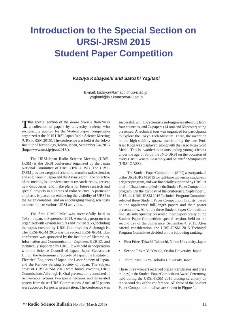
These three winners received prizes (certifi cates and prize money) at the Student Paper Competition Award Ceremony, held during the URSI-JRSM 2015 closing ceremony on the second day of the conference. All three of the Student Paper Competition fi nalists are shown in Figure 1.

12 The Radio Science Bulletin No 356 (March 2016)
The following three papers by the Student Paper Competition fi nalists appear in this special section of the Radio Science Bulletin:
1. “A Quantum Switching System Manipulated by a Light Pulse Pair Designed in Maxwell-Schrödinger Hybrid Algorithm”
Takashi Takeuchi, Shinichiro Ohnuki, and Tokuei Sako Nihon University, Japan
2. “Terahertz Wireless Transmission Enabled by Photonics Using Binary Phase-shift Keying at 300 GHz”
Yu Yasuda1, Shintaro Hisatake1, Shigeru Kuwano2, Jun Terada2, Akihiro Otaka2, and Tadao Nagatsuma1
1Osaka University, Japan 2NTT Corporation, Japan
Figure 1. The URSI-JRSM 2015 Student Paper Competition fi nalists: (l-r) Prof. Kazuya Kobayashi, URSI-JRSM 2015 General Chair; Mr. Takashi Takeuchi, First Prize Winner; Mr. Yu Yasuda, Second Prize Winner; Mr. Li Yi, Third Prize Winner; Prof. Satoshi Yagitani, URSI-JRSM 2015 Technical Program Committee Chair.
3. “Large-Scale Subsurface Velocity Estimation with Array GPR System YAKUMO”
Li Yi, Kazunori Takahashi, and Motoyuki Sato Tohoku University, Japan
We are happy that the Student Paper Competition program at URSI-JRSM 2015 was successful. This success was mainly due to the efforts of the URSI-JRSM 2015 Technical Program Committee. We are very thankful to the members of the committee for their hard work during the selection process. Thanks are also extended to URSI for its fi nancial support for running the program. Finally, we would like to express our appreciation to the Student Paper Competition fi nalists who contributed to this special section.

The Radio Science Bulletin No 356 (March 2016) 13
A Quantum Switching System Manipulated by a Light Pulse Pair
Designed in a Maxwell-Schrödinger Hybrid Algorithm
Takashi Takeuchi1, Shinichiro Ohnuki2, and Tokuei Sako
College of Science and Technology Nihon University, Japan
1E-mail: [email protected]; 2E-mail: [email protected]
Abstract
A novel quantum switching system has been proposed, relying on a two-level system of an electron manipulated by a tailored light pulse pair. A key ingredient in the proposed system was a precise control pulse pair enabling the switching operation, namely an arbitrary and complete transfer of probability densities over the intended two quantum levels. A recently developed highly-accurate scheme for designing the pulse was employed that solved the coupled Maxwell and Schrödinger equations, thus properly taking into account the light-matter interaction. The resultant switching properties clearly showed a high possibility of realizing ultra-fast q-bit operations that are necessary in devising quantum computers.
1. Introduction
Recent, remarkable advancements in laser technology have enabled us to control the quantum states of atoms,
molecules, and quantum dots by laser pulses [1-3]. This innovative technology of controlling quantum systems by external electromagnetic fi elds would be a promising seed for the next-generation key technologies in various applications of electrical and nano engineering. Pioneering efforts in this direction have been already made, aiming at such goals as highly-effi cient state-selective photochemical reactions [4], arbitrary q-bit operations in quantum computation [5], and so on [6].
From the theoretical points of view, dealing with such control problems boils down to the issue of designing an optimal spatiotemporal profi le of the applied laser pulse (hereafter called the light-control pulse). Recent experimental studies have demonstrated that adroit modulation of the laser pulses through a liquid-crystal phase modulator, driven by a genetic algorithm, enables the pulses to control product yields in certain photochemical reactions
[7]. At the same time, signifi cant theoretical progress in the last decade has added a new dimension to the design of light-control pulses, namely designing light-control pulses based on optimal control theory [8-10]. We note here that to our best knowledge, all previous theoretical models have been based on the assumption that the electromagnetic fi eld in the vicinity of the target system is not disturbed by the excited electrons. Although this assumption makes their design schemes so facile as to easily obtain solutions, this assumption was not yet carefully studied: whether the induced electromagnetic fi eld generated from the electrons excited by the incident laser pulse would appreciably modify the original incoming pulse.
Very recently, the authors have carefully examined verifi cation of using this assumption by hybrid simulation of the coupled Maxwell-Schrödinger equations [11]. This hybrid simulation was a novel computational scheme, amenable to effi cient and accurate computation of coupled electron and electromagnetic-fi eld systems, without unnecessary assumptions [11-16]. They focused on the system of a single electron confi ned in a quasi-one-dimensional nanostructure, modeling quantum dots or nanowires, and studied optical control of quantum states between the ground and fi rst-excited states. The results showed that the light-control pulse designed by the conventional scheme [10] could not stably control the electronic states, due to the local modifi cation of the laser pulse by the excited electron. Furthermore, a new scheme of designing light control pulses was then developed by the authors. This scheme incorporated this local modifi cation, and was thus capable of stably controlling the target system.
In the present study, the proposed designed scheme [11] is further explored to study a switching operation for an electron confi ned in a quasi-one-dimensional potential. A comparison between the resultant switching properties obtained by the present Maxwell-Schrödinger hybrid scheme and by the conventional scheme was made. The result clearly showed that a pair of light-control

14 The Radio Science Bulletin No 356 (March 2016)
pulses obtained by the conventional scheme [10] could hardly switch between the two electronic states while the proposed pulse pair did, suggesting that the latter could be an indispensable technology for light-driven ultra-fast computation.
2. Theoretical Model and Formulations
The system studied is schematically illustrated in Figure 1. A single electron is confi ned in a quasi-one-dimensional nanostructure modeling a narrow tube, which is placed along the z axis. This system is illuminated by a pair of light-control pulses polarized along this z axis, which aim at accomplishing switching operations by transferring the probability density of the electron between two target quantum levels. The time-evolution of the total system is simulated by solving the coupled three-dimensional Maxwell’s and one-dimensional Schrödinger equations [11, 14]. The control accuracy of the switching operations is evaluated for the light-control pulses designed by the conventional method [10] and by our proposed methods [11].
The hybrid simulation required us to simultaneously solve both the Maxwell’s equations for the electromagnetic fi eld and the time-dependent Schrödinger equation for the electron. The following Maxwell’s equations were employed in the part determining the electric and magnetic fi elds, E and H :
0 t
EH J , (1)
0 t
HE , (2)
where 0 , 0 , and J respectively represent the permittivity, permeability in a vacuum, and the polarization current density generated by the excited electron.
A single electron subjected to the electromagnetic fi eld can be described by the time-dependent Schrödinger equation with the following Hamiltonian, ˆ AH , which is the quantum analogue of the classical Hamiltonian for a charged particle accounting for the Lorentz force:
12
ˆ A zi H i qA q Vt m z
(3)
where , m , and q respectively indicate the reduced Planck constant, mass, and charge of an electron. zA and in Equation (3) are respectively the z component of the vector potential A and the scalar potential, which are determined in the Lorentz gauge by the following coupled equations:
t
AE , (4)
0 0 0
t
A . (5)
Since the equation of continuity must be satisfi ed for the wave function, , in Equation (3), the polarization current density of the electron can be obtained from
*2*
2z zqJ q A
m z z m
(6)
Figure 1. The geometry and coor-dinates of the studied system. The incident light-control pulse pair is polarized along the z axis, and uniform for the y z plane.
The Radio Science Bulletin No 356 (March 2016) 15
The hybrid simulation of the Maxwell-Schrödinger equations can be performed by simultaneously and recursively updating Equations (1) through (6). A more detailed procedure for actual computation based on the FDTD algorithm [17, 18] may be found in our previous study [11].
According to the conventional design method [10], the light-control pulse, ( )ic
zE , at every moment is obtained by recursively solving the following coupled equations, involving only the time-dependent Schrödinger equation [11]:
02 Imicz
EE Wqzm
, (7)
2 2
2ˆ
2ic
L zi H qE t z Vt m z
, (8)
W , (9)
where represents the length-gauge form of the wave function. This is derived from the original wave function, , in Equation (3) by applying the following unitary transformation, ̂ , within the dipole approximation, namely, , t tA r A as
ˆ , (10)
xpˆ e ziqA t
. (11)
The W operator defi ned by Equation (9) is the projection operator to the objective state .
In our proposed design scheme [11], the light-control pulse, ( )ip
zE , is updated by an equation similar to Equation (7). However, it uses a more-reliable and accurate wave function, , which is obtained by the solution of the coupled Maxwell-Schrödinger equations and a unitary transformation without the dipole approximation, namely,
ˆ , (12)
, exˆ p ziqA z t
. (13)
We note that the spatial dependence in the z component of the vector potential zA guarantees incorporation of the effect of the local modifi cation of the incident light pulse by the electron’s excitation.
3. Computational Results
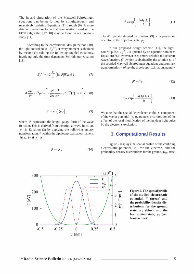
Figure 2 displays the spatial profi le of the confi ning electrostatic potential, V , for the electron, and the probability density distributions for the ground, 0 , state,
Figure 2. The spatial profi le of the studied electrostatic potential, V (green) and the probability density dis-tributions for the ground state, 0 (blue), and the fi rst excited state, 1 (red broken line).

16 The Radio Science Bulletin No 356 (March 2016)
and the fi rst excited, 1 , state. We have employed a pair of light-control pulses for the system studied shown in Figure 1, which transfer the quantum state of the system fi rst from the ground state to the fi rst excited state, and then vice versa, respectively by their fi rst and second pulse components. In this switching operation characterized by 0 1 0 , the record holding time at the intermediate, 1 , state was chosen to be 10 fs. A detailed pulse-designing algorithm is represented in Figure 3, with the following defi nitions of variables:
1 0 10.999999 0.000001I , (14)
1 1 , (15)
2 0 10.000055 0.999945I , (16)
2 0 , (17)
0 0 0| | , (18)
10 1| | , (19)
0.999945aC , (20)
where 1I and 1 are the initial and objective states to control from 0 to 1 , while 2I and 2 are the states to control from 1 to 0 . The reason to reset the wave function by 2I at the intermediate stage of the simulation for both conventional and proposed pulse-designing schemes is to remove a tiny spurious error due to the FDTD algorithm that sometimes leads to quite low control accuracy for the transition from 1 to 0 . This resetting was used only when light-control pulses have been designed, and was not used in the simulation to study the control ability of the light-control pulses. 0 and 1 in Equations (18) and (19) respectively denote the squared norm of the projection of the wave function onto the ground and fi rst excited states, 0 and 1 , where the wave function needs to be replaced by in the case of the conventional pulse-designing scheme. In order to guarantee numerical stability, the time spacing, t , was chosen in the present study to be smaller by a factor of 0.9 than the maximum value allowed by the CFL condition [11]. The temporal profi les of the light-control pulse pairs for this switching operation, designed by our proposed scheme and by the conventional scheme, are both represented in Figure 4. This fi gure clearly shows appreciable differences between the pulse pairs obtained from these two distinct schemes. This then results in a large difference in their control ability for the switching operation, as follows.
Figure 3. A schematic illustra-tion of the pulse-designing algorithm to obtain a pair of the light-control pulses for switching between the initial and objective states.See Equations (14) to (20) for further details.

The Radio Science Bulletin No 356 (March 2016) 17
The spatiotemporal propagation of the probability density of the electron wave packet, the polarization of the current density, zJ , and the electric fi eld, zE , inside the nanotube for the results of the simulation employing the conventional pulse pair are respectively displayed in Figures 5a, 5b, and 5c. In these fi gures, the horizontal and vertical axes respectively indicate the time, t , and the z coordinate in the narrow tube. Figure 5a, representing the result of the electron wave packet for the conventional pulse pair, permanently showed strong oscillations in the probability amplitude after 10t fs when the fi rst laser pulse arrives. This indicated that the conventional control pulse was incapable of not only guiding the electronic state to the fi rst excited state, 1 , but of also resetting it to the ground state, 0 . The resultant oscillations in the probability amplitude led to the strong excitation of the polarization current density, as represented in Figure 5b. There, the oscillatory polarization current density was distributed ranging from 0.25z nm to 0.25 nm. The lowering control accuracy of the conventional control-pulse pair can be rationalized by the induced electromagnetic fi eld from this polarization current density displayed in Figure 5c: At the periods of time 15 fs 20 fst and 45 fs 50 fst when the system was effi ciently illuminated by the light pulse, a strong electric fi eld appeared inside around the electron wave packet ( 0.25z nm). This induced radiation interfered with the original electric fi eld of the incident laser pulse, and thus signifi cantly lowered its control ability.
On the other hand, in the case of our proposed control pulse, the electron wave packet displayed in Figure 6a showed a change of distribution from a single peak to a double peak when the system interacted with the fi rst control pulse. It then returned to its original single-peak distribution of the ground state by the second control pulse. At the same time, the polarization current density displayed in Figure 6b vanished, indicating that the system was transferred completely to the eigenstate. These results
indicated that the ultra-fast switching operation, in the range of a femtosecond timescale, could be successfully achieved by using our proposed control-pulse pair. Another interesting observation made from the present results was that a stable static electric fi eld appeared after the completion of the switching operation from 0 to 1 at around 20 fs to 50 fs, as displayed in Figure 6c. This was caused by the polarization of the electric charge in the fi rst excited state,
1 . This might be used as a “non-destructive detection” of quantum states, if this static fi eld can be safely detected as voltage, or anything.
Finally, in order to quantitatively estimate the control ability of the light-control pulses designed by the conventional scheme and our scheme, we investigated the temporal variation of each component of the electronic states
Figure 4. The temporal profi le of the light-control pulse pairs designed by the conventional scheme and by our scheme. The blue solid and red broken lines respectively represent the conventional and our proposed pulse pairs, ( )ic
zE and ( )ipzE .
Figure 5a. The spatiotemporal propagation of the probability density of the electron wave packet, 2in the narrow tube when the system is irradiated by the conventional pulse pair ( )ic
zE .
Figure 5b. The spatiotemporal propagation of the polarization current density, zJ , in the narrow tube when the system is irradiated by the conventional pulse pair ( )ic
zE .
Figure 5c. The spatiotemporal propagation of the electric fi eld, zE , in the narrow tube when the system is irradiated by the conventional pulse pair ( )ic
zE .

18 The Radio Science Bulletin No 356 (March 2016)
in the time-dependent electron wave packets 0 and 1as shown in Figure 7. The results from the conventional pulses, ( )ic
zE , represented by the solid lines in Figure 7, showed an incomplete switching property, in which only 30% of the probability density could be transferred in both directions from the ground state to the fi rst excited state, and vice versa. This incomplete transfer also manifested itself in the high-frequency and small-amplitude oscillations in 0 and 1 that appeared after 10t fs. This small oscillation of 0 and 1 originated from the self-interaction between the electron and the local electromagnetic fi eld induced by the oscillatory wave packet of the electron itself, which permanently provided the polarization current density, as represented in Figure 5. On the other hand, in the case of the results from our designed pulse pair ( )ip
zE , 0 and 1 changed their values between unity and naught, indicating complete transfer of the probability density in both directions. These results indicated that a pair of the light-control pulses designed by our proposed scheme were capable of performing ultra-fast and stable switching operations.
4. Conclusions
In this paper, we have proposed a novel switching system relying on a quantum two-level system, manipulated by a light-control pulse pair. The critical issue to realizing such a control system was to design a proper pulse pair that took into account modifi cation of the incident control
pulses in the vicinity of the target system by the electron excitation. For this purpose, we employed a highly-accurate Maxwell-Schrödinger hybrid simulation that considered the feedback from the electron system to the incident electromagnetic fi eld. We examined the control abilities of the light-control pulses designed by our proposed scheme and by a conventional scheme that neglected this effect of the local modifi cation. The resultant simulation clearly showed that our pulse pair achieved an arbitrary and complete transfer of the probability density of the electron over the intended quantum levels, while the conventional pulse could hardly perform such an ideal control. The present results indicated that the proposed light-control pulse can be an indispensable tool for ultra-fast objective switching.
Figure 6a. The spatiotemporal propagation of the probability density of the electron wave packet, 2in the narrow tube when the system is irradiated by our proposed pulse pair ( )ip
zE .
Figure 6b. The spatiotemporal propagation of the polarization current density, zJ , in the narrow tube when the system is irradiated by our proposed pulse pair ( )ip
zE .
Figure 6c. The spatiotemporal propagation of the electric fi eld, zE , in the narrow tube when the sys-tem is irradiated by our proposed pulse pair ( )ip
zE .
Figure 7. The temporal variation of the contribution of the ground state ( 0 ) and the fi rst excited states (
1 ) in the time-dependent electron wave packet for the two types of light-control pulses designed by the conventional scheme and by our proposed scheme. The results for the control pulse transferring the probability density from the ground state to the fi rst excited state are colored by blue and cyan, and those from the fi rst excited state to the ground state are colored by magenta and red. In both cases, the results from the conventional pulse, ( )ic
zE , are represented in solid lines, and those from our proposed pulse, ( )ip
zE , are shown in broken lines.

The Radio Science Bulletin No 356 (March 2016) 19
5. Acknowledgements
The authors would like to thank Profs. K. Nakagawa, Y. Ashizawa (Nihon University), and M. Tanaka (Gifu University) for their useful comments and suggestions. This work was partly supported by Grant-in-Aid for Scientifi c Research (C) (No. 26420321) and MEXT-Supported Program for the Strategic Research Foundation at Private Universities, 2013-2017. One of the authors (T. S.) also acknowledges MEXT for fi nancial support [Grants-in-Aid for Scientifi c Research (C) (No. 15K05396) and Grants-in-Aid for Scientifi c Research on Innovative Areas (No. 25110006)].
6. References
1. D. Meshulach and Y. Silberberg, “Coherent Quantum Control of Two-Photon Transitions by a Femtosecond Laser Pulse,” Nature, 396, 19, November 1998, pp. 239-242.
2. H. Rabitz, R. De Vivie-Riedle, M. Motzkus, and K. Kompa, “Whiter the Future of Controlling Quantum Phenomena?,” Science, 288, 5467, May 2000, pp. 824-828.
3. D. Brinks, F. D. Stefani, F. Kulzer, R. Hildner, T. H. Taminiau. Y. Avlasevich, K. Müllen, and N. F. van Hulst, “Visualizing and Controlling Vibrational Wave Packets of Single Molecules,” Nature, 465, 17, June 2010, pp. 905-908.
4. C. J. Bardeen, J. Che, K. R. Wilson, V. V. Yakovlev, P. Cong, B. Kohler, J. L. Krause, and M. Messina “Quantum Control of NaI Photodissociation Reaction Product States by Ultrafast Tailored Light Pulses,” The Journal of Physical Chemistry A, 101, 20, May 1997, pp. 3815-3822.
5. P. Domokos, J. M. Raimond, M. Brune, and S. Haroche, “Simple Cavity-QED Two-Bit Universal Quantum Logic Gate: The Principle and Expected Performances,” Physical Review A, 52, 5, November 1995, pp. 3554-3559.
6. Md. Z. Hoque, M. Lapert, E. Hertz, F. Billard, D. Sugny, B. Lavorel, and O. Faucher, “Observation of Laser-Induced Field-Free Permanent Planar Alignment of Molecules,” Physical Review A, 84, 1, July 2011, pp. 013409-1-013409-6.
7. C. Daniel, J. Full, L. González, C. Lupulescu, J. Manz, A. Merli, Š. Vajda, and L. Wöste, “Deciphering the Reaction Dynamics Underlying Optimal Control Laser Fields,” Science 299, 5606, January 2003, pp. 536-539.
8. A. P. Peirce and M. A. Dahleh, “Optimal Control of Quantum-Mechanical Systems: Existence, Numerical Approximation, and Applications,” Physical Review A, 37, 12, June 1988, pp. 4950-4964.
9. S. Shi and H. Rabitz, “Quantum Mechanical Optimal Control of Physical Observables in Microsystems,” The Journal of Chemical Physics, 92, 1, January 1990, pp. 364-376.
10. Y. Ohtsuki, H. Kono, and Y. Fujimura, “Quantum Control of Nuclear Wave Packets by Locally Designed Optimal Pulses,” The Journal of Chemical Physics, 109, 21, December 1998, pp. 9318-9331.
11. T. Takeuchi, S. Ohnuki, and T. Sako, “Maxwell-Schrödinger Hybrid Simulation for Optically Controlling Quantum States: A Scheme for Designing Control Pulses,” Physical Review A, 91, 3, March 2015, pp. 033401-1-033401-13.
12. I. P. Christov, M. M. Murnane, and H. C. Kapteyn, “Generation and Propagation of Attosecond X-Ray Pulses in Gaseous Me-dia,” Physical Review A, 57, 4, April 1998, pp. R2285-R2288.
13. E. Lorin, S. Chelkowski, and A. Bandrauk, “A Numerical Maxwell-Schrödinger Model for Intense Laser-Matter Interac-tion and Propagation,” Computer Physics Communications, 177, 12, December 2007, 908-932.
14. L. Pierantoni, D. Mencarelli, and T. Rozzi, “A New 3-D Trans-mission Line Matrix Scheme for the Combined Schrödinger-Maxwell Problem in the Electronic/Electromagnetic Charac-terization of Nanodevices,” IEEE Transactions on Microwave Theory and Techniques, 56, 3, March 2008, 654-662.
15. T. Takeuchi, S. Ohnuki, and T. Sako, “Comparison Between Maxwell-Schrödinger and Maxwell-Newton Hybrid Simula-tions for Multi-Well Electrostatic Potential,” IEEE Journal of Quantum Electronics, 50, 5, March 2014, pp. 334-339.
16. T. Takeuchi, S. Ohnuki, and T. Sako, “Hybrid Simulation of Maxwell-Schrödinger Equations for Multi-Physics Prob-lems Characterized by Anharmonic Electrostatic Potential,” Progress in Electromagnetics Research, 148, July 2014, pp.73-82.
17. K. S. Yee, “Numerical Solution of Initial Boundary Value Problems Involving Maxwell’s Equations in Isotropic Media,” IEEE Transactions on Antennas and Propagation, 14, 3, May 1996, pp. 302-307.
18. A. Soriano, E. A. Navarro, J. A. Porti, and V. Such, “Analysis of the Finite Difference Time Domain Technique to Solve the Schrödinger Equation for Quantum Devices,” Journal of Applied Physics, 95, 12, June 2004, pp. 8011-8018.

20 The Radio Science Bulletin No 356 (March 2016)
Terahertz Wireless Transmission Enabled by Photonics Using Binary Phase-Shift
Keying at 300 GHz
Y. Yasuda1, S. Hisatake1, S. Kuwano2, J. Terada2, A. Otaka2, and T. Nagatsuma1
1Graduate school of Engineering ScienceOsaka University
1-3 Machikaneyama, Toyonaka, Osaka 560-8531, JapanE-mail: [email protected]
2NTT Access Network Service Systems LaboratoriesNTT Corporation
1-1 Hikari-no-oka, Yokosuka, Kanagawa 239-0847, Japan
Abstract
This paper presents the fi rst real-time wireless transmission at 300 GHz using binary phase-shift keying (BPSK) modulation. A coherent transmitter based on photonics enabled an error-free transmission (bit-error rate:
11BER 10 ) at a record data rate of 40 Gbit/s. In order to stabilize the frequency and phase of carrier signals in the transmitter, we proposed and demonstrated an active phase-stabilization technique using an optical frequency comb (OFC). Our method is applicable to more complicated modulation formats to increase the data rate of real-time terahertz communications to over 100 Gbit/s.
1. Introduction
Recently, there has been a growing interest in the application of terahertz (THz) waves (0.1 THz to
10 THz) to ultra-fast wireless communications [1, 2]. The use of photonic techniques to generate and modulate carrier signals in the transmitter has proven to be effective in achieving data rates of over 10 Gbit/s at 120 GHz [3], 240 GHz [4], 300 GHz [5], and 400 GHz [6], as summarized in Table 1. Potential applications include wireless local-area networks; wireless personal-area networks; near-fi eld communications, such as kiosk downloading; wireless connections in data centers; device-to-device communications; wireless backhauling, etc. [7].
The highest data rate with “real-time” transmission was 40 Gbit/s with an on-off keying (OOK) modulation at 300 GHz. To increase data rates, coherent transmission systems with multi-level modulation formats, such as quadrature phase-shift keying (QPSK), 8-quadrature amplitude modulation (QAM), and 16 QAM, have been examined to show the highest data rate of 100 Gbit/s with a bit-error rate (BER) of 33 10 at 240 GHz, which was estimated by “offl ine” digital signal processing (DSP).
Carrier Fre-quency
Modulation Scheme Data Rate Detection Scheme Measurement
Method BER Reference
120 GHz OOK 10 Gbit/s Direct detection Real time 1110 [3]
237.5 GHz 16QAM 100 Gbit/s Coherent detection Off-line DSP 33.4 10 [4]
305 GHz OOK 40 Gbit/s Direct detection Real time 1110 [5]
400 GHz OOK 40 Gbit/s Coherent detection Off-line DSP 31 10 [6]
330 GHz BPSK 40 Gbit/s Coherent detection Real time 1110 This work
Table 1. A comparison of photonics-based THz wireless transmission systems.

The Radio Science Bulletin No 356 (March 2016) 21
One of the practical issues in the previous coherent systems based on photonics is a phase instability of carrier signals in the transmitter. In such a system, as shown in Figure 1a, two optical modes fi ltered from the optical frequency comb (OFC) undergo phase changes in each optical fi ber before being combined in the photodiode, which leads to the phase fl uctuation of the carrier signals. As a result, not only is complicated digital signal processing required in the receiver to estimate a BER by compensating for the phase fl uctuation, but a forward error correction (FEC) is also required in the receiver to achieve error-free transmission, due to the inherently poor BER.
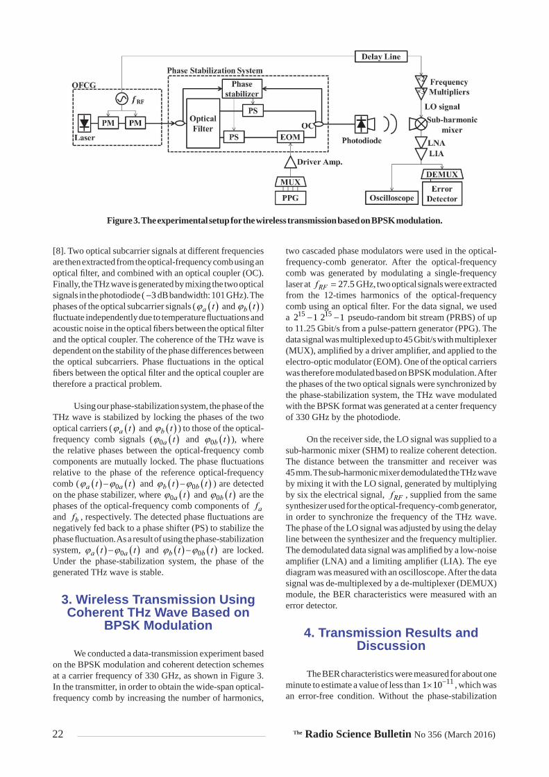
In this paper, we propose a new approach to actively stabilize the phase of carrier signals in the transmitter, as shown in Figure 1b. We demonstrate a real-time coherent transmission using binary phase-shift-keying (BPSK) modulation at 300 GHz. In our proof-of-concept experiments, in order to study the effectiveness of our coherent transmitter, the local oscillator (LO) signal for
the receiver was supplied from the same synthesizer used for an optical-frequency-comb generator (OFCG). We fi rst describe a frequency- and phase-stabilized transmitter based on the optical-frequency-comb generator with a phase-stabilization system. We next explain a confi guration of a 300 GHz band wireless transmission using the BPSK format, and demonstrate real-time transmission without the digital signal processing up to 45 Gbit/s.
2. Generation of Coherent THz Wave
Figure 2 shows a schematic diagram of the THz-wave generation system, using the optical-frequency-comb generator with a carrier-phase-stabilization system. The phase of a single-frequency laser is fi rst modulated with two cascaded phase modulators (PMs) to generate the optical-frequency comb. The wide-span optical-frequency comb can be generated by using two cascaded phase modulators
Figure 1. Schematic diagrams of coherent wireless transmission: (a) The use of digital signal processing (DSP) on the receiver side; (b) The use of a phase-stabilization system on the transmitter side.
Figure 2. A schematic diagram of the coherent THz-wave transmitter.
22 The Radio Science Bulletin No 356 (March 2016)
[8]. Two optical subcarrier signals at different frequencies are then extracted from the optical-frequency comb using an optical fi lter, and combined with an optical coupler (OC). Finally, the THz wave is generated by mixing the two optical signals in the photodiode ( 3 dB bandwidth: 101 GHz). The phases of the optical subcarrier signals ( a t and b t ) fl uctuate independently due to temperature fl uctuations and acoustic noise in the optical fi bers between the optical fi lter and the optical coupler. The coherence of the THz wave is dependent on the stability of the phase differences between the optical subcarriers. Phase fl uctuations in the optical fi bers between the optical fi lter and the optical coupler are therefore a practical problem.
Using our phase-stabilization system, the phase of the THz wave is stabilized by locking the phases of the two optical carriers ( a t and b t ) to those of the optical-frequency comb signals ( 0a t and 0b t ), where the relative phases between the optical-frequency comb components are mutually locked. The phase fl uctuations relative to the phase of the reference optical-frequency comb ( 0a at t and 0b bt t ) are detected on the phase stabilizer, where 0a t and 0b t are the phases of the optical-frequency comb components of af and bf , respectively. The detected phase fl uctuations are negatively fed back to a phase shifter (PS) to stabilize the phase fl uctuation. As a result of using the phase-stabilization system, 0a at t and 0b bt t are locked. Under the phase-stabilization system, the phase of the generated THz wave is stable.
3. Wireless Transmission Using Coherent THz Wave Based on
BPSK Modulation
We conducted a data-transmission experiment based on the BPSK modulation and coherent detection schemes at a carrier frequency of 330 GHz, as shown in Figure 3. In the transmitter, in order to obtain the wide-span optical-frequency comb by increasing the number of harmonics,
two cascaded phase modulators were used in the optical-frequency-comb generator. After the optical-frequency comb was generated by modulating a single-frequency laser at 27.5RFf GHz, two optical signals were extracted from the 12-times harmonics of the optical-frequency comb using an optical fi lter. For the data signal, we used a 152 1 152 1 pseudo-random bit stream (PRBS) of up to 11.25 Gbit/s from a pulse-pattern generator (PPG). The data signal was multiplexed up to 45 Gbit/s with multiplexer (MUX), amplifi ed by a driver amplifi er, and applied to the electro-optic modulator (EOM). One of the optical carriers was therefore modulated based on BPSK modulation. After the phases of the two optical signals were synchronized by the phase-stabilization system, the THz wave modulated with the BPSK format was generated at a center frequency of 330 GHz by the photodiode.
On the receiver side, the LO signal was supplied to a sub-harmonic mixer (SHM) to realize coherent detection. The distance between the transmitter and receiver was 45 mm. The sub-harmonic mixer demodulated the THz wave by mixing it with the LO signal, generated by multiplying by six the electrical signal, RFf , supplied from the same synthesizer used for the optical-frequency-comb generator, in order to synchronize the frequency of the THz wave. The phase of the LO signal was adjusted by using the delay line between the synthesizer and the frequency multiplier. The demodulated data signal was amplifi ed by a low-noise amplifi er (LNA) and a limiting amplifi er (LIA). The eye diagram was measured with an oscilloscope. After the data signal was de-multiplexed by a de-multiplexer (DEMUX) module, the BER characteristics were measured with an error detector.
4. Transmission Results and Discussion
The BER characteristics were measured for about one minute to estimate a value of less than 111 10 , which was an error-free condition. Without the phase-stabilization
Figure 3. The experimental setup for the wireless transmission based on BPSK modulation.

The Radio Science Bulletin No 356 (March 2016) 23
system, we could not measure the BER because of signifi cant phase changes of the THz wave. Figure 4 shows the BER characteristics at bit rates of 40 Gbit/s and 45 Gbit/s, and the eye diagram at 40 Gbit/s. The maximum bit rate of 40 Gbit/s under the error-free condition was successfully achieved for a wireless distance at 45 mm. A BER of 123.6 10 was obtained at 40 Gbit/s, when the transmitter power was 21 dBm. A BER of 61.6 10 was also obtained at 45 Gbit/s, when the transmitter power was 19 dBm. The main reason why we could not reach an error-free condition at 45 Gbit/s was a bandwidth limitation of the electro-optic modulator ( 3 dB bandwidth: 25 GHz) used to modulate the phase of the coherent THz wave.
As for our experiment, we used a horn antenna with a gain of 25 dBi for both the transmitter and receiver, which limited the transmission distance to less than 50 mm. For practical applications, high-gain antennas, such as a Cassegrain antenna and a lens antenna, could be used to extend the link distance to more than 20 m, as described in [9].
5. Conclusion
We have demonstrated 300 GHz band wireless transmission using a photonics-based BPSK transmitter and a coherent receiver. We confi rmed error-free transmission up to 40 Gbit/s without digital signal processing on the receiver side. In our future work, multilevel modulation formats, such as QPSK, will be introduced to enhance the data rate to 100 Gbit/s.
6. Acknowledgments
This work was partly supported by the 2015 Strategic Information and Communications R&D Promotion Programme (SCOPE) 135010103, from the Ministry of Internal Affairs and Communications, Japan.
7. References
1. J. Federici, and L. Moeller, “Review of Terahertz and Subtera-hertz Wi reless Communications,” Journal of Applied Physics, 107, 11, June 2010, p. 111101.
2. T. Kleine-Ostmann and T. Nagatsuma, “A Review on Terahertz Communications Research,” Journal of Infrared, Millimeter, and Terahertz Waves, 32, 2, January 2011, pp. 143-171.
3. A. Hirata, R. Yamaguchi, T. Kosugi, H. Takahashi, and K. Mu-rata, et al., “10-Gbit/s Wireless Link Using InP HEMT MMICs for Generating 120-GHz-band Millimeter-Wave Signal,” IEEE Transactions on Microwave Theory and Techniques, 57, 5, May 2009, pp. 1102-1109.
4. S. Koenig, F. Boes, D. Lopez-Diaz, J. Antes, and R. Hen-neberger, et al., “100 Gbit/s Wireless Link with mm-Wave Photonics,” Optical Fiber Communication Conference and Exposition and the National Fiber Optics Engineers Conference (OFC/NFOEC), Anaheim, California, March 17-21, 2013.
5. T. Nagatsuma, “Generating Millimeter and Terahertz Waves by Photonics for Communications and Sensing,” Microwave Symposium Digest (IMS), Seattle, Washington, June 2-7, 2013.
6. G. Ducournau, P. Szriftgiser, A. Beck, D. Bacquet, and F. Pavanello, et al., “Ultrawide-Bandwidth Single-Channel 0.4-THz Wireless Link Combining Broadband Quasi-Optic Photomixer and Coherent Detection,” IEEE Transactions on THz Science and Techniques, 4, 3, May 2014, pp. 328-337.
7. T. Kürner and S. Priebe, “Towards THz Communications – Status in Research, Standardization and Regulation,” Journal of Infrared, Millimeter, and Terahertz Waves, 35, 1, January 2014, pp. 53-62.
8. J. Zhang, J. Yu, L. Tao, Y. Fang, and Y. Wang, et al., “Genera-tion of Coherent and Frequency-Lock Optical Subcarriers by Cascading Phase Modulators Driven by Sinusoidal Sources,” Journal of Lightwave Technology, 30, 24, December 2012, pp. 3911-3917.
9. T. Nagatuma, and G. Carpintero, “Recent Progress and Future Prospect of Photonics-Enabled Terahertz Communications Research,” IEICE Transactions on Electronics, 98, 12, De-cember 2015, pp. 1060-1070.
Figure 4. The BERcharac ter i s t i c s a t 40 Gbit/s and 45 Gbit/s, and an eye diagram at 40 Gbit/s.
24 The Radio Science Bulletin No 356 (March 2016)
Large-Scale Subsurface Velocity Estimation with YAKUMO
GPR Array System Li Yi1, Kazunori Takahashi2, and Motoyuki Sato2
1Graduate School of Environmental Studies Tohoku University41 Kawauchi, Aoba-Ku, Sendai 980-8576, Japan
E-mail: [email protected]
2Center of Northeast Asian StudiesTohoku University
41 Kawauchi, Aoba-Ku, Sendai 980-8576, JapanE-mail: [email protected];
Abstract
We demonstrate an approach for estimating the velocity of electromagnetic wave propagation in a subsurface medium with a ground-penetrating radar (GPR) array system, “YAKUMO.” The common-midpoint (CMP) data acquired by YAKUMO at each position can be used to estimate the velocity at different depths. We removed the aliasing components from the sparsely acquired common-midpoint dataset so that the artifacts can be prevented while automatically picking the velocity. The velocity profi le can hence be generated. We tested our approach with the data obtained on the pavement of an airport-runway model. Beside the manmade voids that could easily be detected, we also found that the area with a velocity of about 0.03 m/ns lower than the surrounding areas indicated the location where manmade grooves existed. This indicated that the estimated velocity changes may be used to detect damaged pavement, even when there is no clear refl ection from the cracks appearing in the GPR profi le.
1. Introduction
Ground-penetrating radar (GPR) is a powerful tool that is used for subsurface exploration. It is a nondestructive
method, and can provide the highest resolution among all methods of subsurface imaging. In previous research, it has been shown that the GPR technique has many advantages, which leads to its wide use in different fi elds [1].
We are conducting a research project on the monitoring of pavement at airport runways by using ground-based SAR and array-type GPR. In this research project, we are developing radar technologies to detect the defects or anomalies that occurred inside the pavement of the surface of the pavement of the runway and taxiway or parking apron in airports.
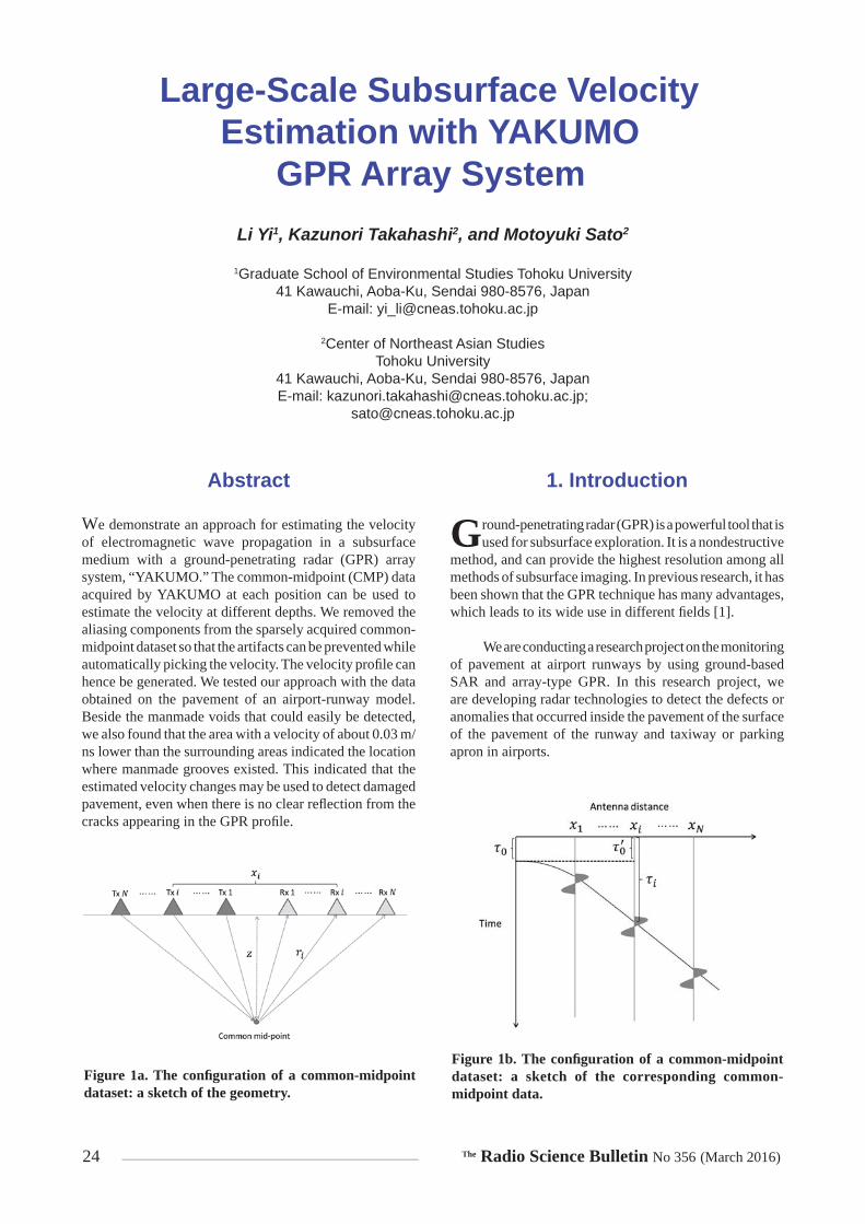
Figure 1a. The confi guration of a common-midpoint dataset: a sketch of the geometry.
Figure 1b. The confi guration of a common-midpoint dataset: a sketch of the corresponding common-midpoint data.

The Radio Science Bulletin No 356 (March 2016) 25
We fi rst introduce the theory, which uses the common-midpoint dataset to estimate the velocity of electromagnetic wave propagation in the subsurface medium. In previous work, we applied this method with a bistatic GPR system to acquire the common-midpoint dataset. However, the data acquisition is very complicated for a common-midpoint dataset at one fi xed position. In most cases, we have to use limited information: for example, we have to decide only a few common-midpoint points based on the knowledge of hydrology to estimate the subsurface properties in a relatively large area [2]. In order to improve the effi ciency of the data acquisition, we developed a new array GPR system, YAKUMO. With this multi-static GPR system, we can estimate the subsurface velocity at every position while operating the system on a survey line. However, due to the limitation of the size of the antenna, the array GPR system YAKUMO can only acquire eight traces for a common-midpoint dataset. In previous research, it was already shown that the resolution of the velocity estimation is mainly related to the largest distance between two antennas. However, artifacts may be introduced if there only a few antenna combinations exist within this distance [3]. This problem also happened to our YAKUMO system, because we only had eight traces within more than a two-meter maximum distance. The artifacts made it diffi cult to automatically pick the velocity. In this case, we introduced a method to enhance the estimated results by removing the aliasing components caused by the coarse sampling and then interpolating the common-midpoint dataset, so that the velocity could be automatically picked at every position. We also show how the velocity estimation could be enhanced with the real data acquired at a sand dune. The result also indicated that the velocity of multiple layers can be acquired for hydrology research.
In our project, we mainly focus on estimating the slight velocity changes within single-layer refl ections, such as for the inspection of pavement. With dense velocity information, a vertical velocity profi le can be generated
along a survey line, and the slight velocity changes within a certain depth can be detected with the velocity profi le. We tested our approach at an experimental site of an airport-runway model. The results showed that the velocity profi le could be used to detect some damage that was hard to detect with common GPR data.
2. Velocity Estimation by GPR
Common-midpoint data is a unique dataset that can be acquired by a bistatic GPR system. The vertical root-mean-square (RMS) velocity of electromagnetic wave propagation in subsurface layers can be estimated from a common-midpoint dataset. Its successful applications have been demonstrated, for example, for the estimation of hydraulic properties [2].
For the common-midpoint analysis at a fi xed position, refl ected signals need to be measured at both sides of the middle point with different antenna distances, as shown in Figure 1a. If the subsurface is homogeneous and horizontally layered, the two-way travel time, i , of the refl ection signal can be given by Equation (1):
2
20 2
ii
xv
, (1)
where
2
24i
ixr z , (2)
1
, , ,N
i ii
P v z d v z x
, (3)
Figure 2a. The simulated common-midpoint dataset. Figure 2b. The velocity spectrum of the simulated common-midpoint dataset.

26 The Radio Science Bulletin No 356 (March 2016)
where z is the depth of the horizontal refl ector, ix is the distance between the antenna pair the elements of which are denoted by i, v is the trial velocity, N is the number of the traces, and d is the common-midpoint data. A sketch of the corresponding common-midpoint data of a horizontal refl ector is shown in Figure 1b. After a common-midpoint dataset is acquired, we can apply the velocity analysis to obtain the velocity spectrum, P, with Equation (3). The velocity spectrum shows the stacked amplitude of the signals at different positions along the hyperbolic curves given by Equation (1). When a trial velocity is close to the real velocity, the stacked energy will be enhanced. We can hence pick the estimated velocity at the maximum-energy point.
Figure 2 shows a simple simulated common-midpoint dataset and its velocity spectrum. Here, we assumed that there was only one refl ector, located at 0.5 m depth, with 0.12 m/ns subsurface velocity. We can fi nd that due to the different distance between the antenna pairs the refl ected signal conformed to a hyperbolic curve as shown in Figure 2a. The direct coupling was also included, and that is shown as a straight line. After the velocity analysis, we could acquire the velocity spectrum as shown in Figure 2b. We found that the energy was well focused at the position where the velocity was equal to 0.12 m/ns. The quality of the velocity spectrum is related to the length of a common-midpoint survey line, which is decided by the largest distance of an antenna pair for a multi-static system, the wavelength of the signal, the signal-to-noise ratio (SNR), and the update step of the trial velocity. Artifacts may also be introduced when the data are very coarse, as we mentioned before. More details on common-midpoint analysis can be found in [2, 3].
3. Velocity Estimation by GPR Array System YAKUMO
As we introduced above, the common-midpoint measurement is very time consuming and complicated
with the common bistatic GPR system. Until now, there has been no system specifi cally developed for common-midpoint measurements, and we thus usually have to manually move the antennas. When we want to estimate the velocities at different positions or we want to get the velocity distribution, this method is not practical.
In order to simplify the three-dimensional GPR data and the common-midpoint data acquisition, we developed a new array system, YAKUMO, a few years ago. YAKUMO is about two meters wide. It has eight transmitting and eight receiving antennas, as shown in Figure 3. It is a stepped-frequency continuous-wave (SFCW) system operated between 10 MHz and 1.5 GHz. All the transmitters and receivers can be sequentially switched, so we can acquire all the traces with eight by eight antenna combinations. After it acquires the data along a survey line, a three-dimensional data cube can be generated with synthetic-aperture radar (SAR) processing [1].
With this antenna confi guration, it is also possible to acquire the common-midpoint data at a fi xed position, as Figure 4 shows. Due to the size of the antennas, each trace of the common-midpoint data is not placed on a line. Compared to the confi gurations of the usual common-midpoint measurements, the common-midpoint data acquisition of the YAKUMO system is very fast and convenient. As the trade-off, the common-midpoint data acquired by the YAKUMO system includes only eight traces, and the spatial intervals of the antenna distances between the different antenna pairs are not unique. As we mentioned in the previous section, the coarse common-midpoint data generates artifacts in the velocity spectrum, and this makes automatic velocity picking much more diffi cult. A straightforward approach is to regularize the common-midpoint data to a fi ner grid. However, due to the features of the common-midpoint data, it includes strong aliasing: the interpolation of the common-midpoint data is hence very diffi cult [4]. In this case, we proposed a method to remove the aliasing that allows a common-midpoint gather to be reconstructed with only a few available traces.
From the view of imaging processing, the aliasing is generated by tilted linear objects that are not well sampled. Here, we try to use a trial velocity to regularize the antenna pairs with different distances to zero distance. This can be
Figure 3. The operation of the YAKUMO system.
Figure 4. The antenna confi guration of the YA-KUMO system.

The Radio Science Bulletin No 356 (March 2016) 27
calculated for each antenna pair from the geometry with Equation (4):
2
20 2
ii
xv
, (4)
where i is the two-way travel time with different antenna distances ix , and 0 is the estimated two-way travel time when the distance between the antenna pair is zero. A sketch fi gure in the time domain is shown in Figure 1b, which corresponds to Figure 1a. Here, we should note that the trail velocity, v, is unknown, so that 0 is not equal to 0 . As we mentioned above, the travel times with different antenna pairs are shown as hyperbolic curves in the common-midpoint dataset, which can include strong aliasing when it is not well sampled. If we know the accurate velocity, the hyperbolic curve can then be fl attened to a horizontal refl ection by using the time delay acquired by Equation (4). Here, the trial velocity can be seen as an initial value that is used for accurate velocity estimation.
We can hence use a trial velocity that is estimated within the current survey area when the subsurface velocity does not dramatically change. After removal of the aliasing, we apply an interpolation method that can handle the irregular data to reconstruct the common-midpoint dataset [4]. At the end, we do the inverse correction to remove the time shift we acquired by Equation (3). Figure 5 shows the processing schedule of the proposed method. Figure 5a shows a simple simulated common-midpoint dataset, which included a direct coupling and a layer refl ection with 0.12 m/ns subsurface velocity at 0.5 m depth. We showed a similar confi guration to the YAKUMO system, where there were only eight traces available while the antenna offset reached to two meters. Figure 5b shows the fl attened refl ect signals with an inaccurate velocity of 0.15 m/ns. As this fi gure shows, the refl ected signal was not perfectly fl attened, but went slightly upward, and the direct coupling was not a hyperbolic curve, so it was not correctly fl attened. However, as the interpolated result showed, the refl ected signal was correctly interpolated, because it was still substantially fl attened by the removal of aliasing. However, the direct coupling could not be well interpolated because of the aliasing problem we discussed
(a) (b)
(c) (d)
Figure 5. The processing of a simulated common-midpoint dataset with the proposed method: (a) the raw data; (b) after aliasing removal by the forward transform; (c) after interpolation; (d) after the inverse transform.
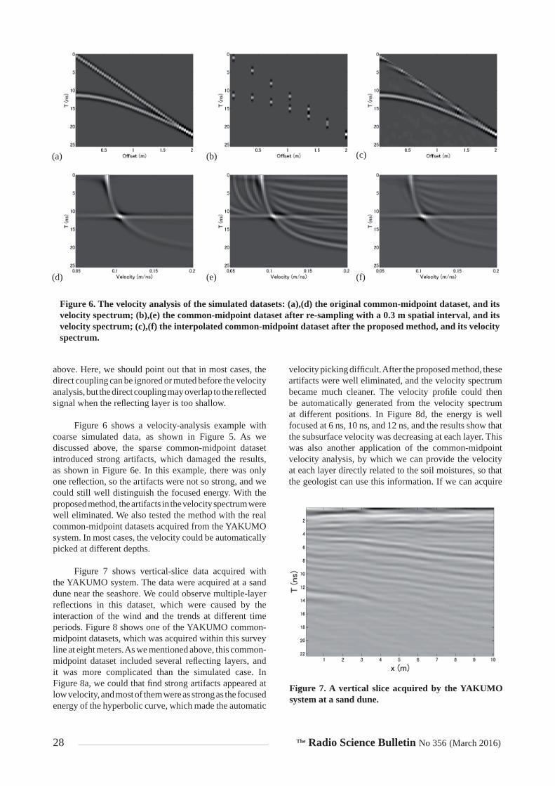
28 The Radio Science Bulletin No 356 (March 2016)
above. Here, we should point out that in most cases, the direct coupling can be ignored or muted before the velocity analysis, but the direct coupling may overlap to the refl ected signal when the refl ecting layer is too shallow.
Figure 6 shows a velocity-analysis example with coarse simulated data, as shown in Figure 5. As we discussed above, the sparse common-midpoint dataset introduced strong artifacts, which damaged the results, as shown in Figure 6e. In this example, there was only one refl ection, so the artifacts were not so strong, and we could still well distinguish the focused energy. With the proposed method, the artifacts in the velocity spectrum were well eliminated. We also tested the method with the real common-midpoint datasets acquired from the YAKUMO system. In most cases, the velocity could be automatically picked at different depths.
Figure 7 shows vertical-slice data acquired with the YAKUMO system. The data were acquired at a sand dune near the seashore. We could observe multiple-layer refl ections in this dataset, which were caused by the interaction of the wind and the trends at different time periods. Figure 8 shows one of the YAKUMO common-midpoint datasets, which was acquired within this survey line at eight meters. As we mentioned above, this common-midpoint dataset included several refl ecting layers, and it was more complicated than the simulated case. In Figure 8a, we could that fi nd strong artifacts appeared at low velocity, and most of them were as strong as the focused energy of the hyperbolic curve, which made the automatic
velocity picking diffi cult. After the proposed method, these artifacts were well eliminated, and the velocity spectrum became much cleaner. The velocity profi le could then be automatically generated from the velocity spectrum at different positions. In Figure 8d, the energy is well focused at 6 ns, 10 ns, and 12 ns, and the results show that the subsurface velocity was decreasing at each layer. This was also another application of the common-midpoint velocity analysis, by which we can provide the velocity at each layer directly related to the soil moistures, so that the geologist can use this information. If we can acquire
(a) (b) (c)
(d) (e) (f)
Figure 6. The velocity analysis of the simulated datasets: (a),(d) the original common-midpoint dataset, and its velocity spectrum; (b),(e) the common-midpoint dataset after re-sampling with a 0.3 m spatial interval, and its velocity spectrum; (c),(f) the interpolated common-midpoint dataset after the proposed method, and its velocity spectrum.
Figure 7. A vertical slice acquired by the YAKUMO system at a sand dune.
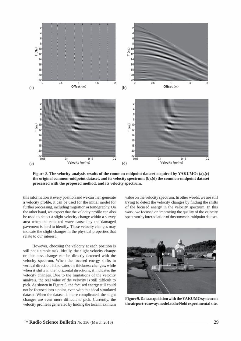
The Radio Science Bulletin No 356 (March 2016) 29
this information at every position and we can then generate a velocity profi le, it can be used for the initial model for further processing, including migration or tomography. On the other hand, we expect that the velocity profi le can also be used to detect a slight velocity change within a survey area when the refl ected wave caused by the damaged pavement is hard to identify. These velocity changes may indicate the slight changes in the physical properties that relate to our interest.
However, choosing the velocity at each position is still not a simple task. Ideally, the slight velocity change or thickness change can be directly detected with the velocity spectrum. When the focused energy shifts in vertical direction, it indicates the thickness changes; while when it shifts in the horizontal directions, it indicates the velocity changes. Due to the limitations of the velocity analysis, the real value of the velocity is still diffi cult to pick. As shown in Figure 5, the focused energy still could not be focused into a point, even with this ideal simulated dataset. When the dataset is more complicated, the slight changes are even more diffi cult to pick. Currently, the velocity profi le is generated by fi nding the local maximum
value on the velocity spectrum. In other words, we are still trying to detect the velocity changes by fi nding the shifts of the focused energy in the velocity spectrum. In this work, we focused on improving the quality of the velocity spectrum by interpolation of the common-midpoint dataset.
(a) (b)
(c) (d)
Figure 8. The velocity-analysis results of the common-midpoint dataset acquired by YAKUMO: (a),(c) the original common-midpoint dataset, and its velocity spectrum; (b),(d) the common-midpoint dataset processed with the proposed method, and its velocity spectrum.
Figure 9. Data acquisition with the YAKUMO system on the airport-runway model at the Nobi experimental site.

30 The Radio Science Bulletin No 356 (March 2016)
A more-advanced method of velocity-profi le generation is still under investigation.
4. Application of the Velocity Profi le Generated by YAKUMO
Here, we show an example that uses the velocity information for inspection of damaged pavement. This is related to the strategic innovation promotion (SIP) project in which we are now involved. The data was acquired at an airport-runway model at the “Port and Airport Research Institute,” located in Nobi, Kanagawa prefecture, Japan. The experimental site is shown in Figure 9, and we selected a part of it as the main area. This main area was a 15 m by 7 m rectangular area, and a sketch map is shown in Figure 10. We defi ned the 15 m side as the x direction, and the other side as the y direction. There were two manmade voids located at around 0.1 m depth along the y direction. They were located at 4x m and 9x m, respectively. In most of the GPR vertical profi les, these voids could easily be detected. However, due to the other scatterers or the complexity of the subsurface, the accurate position of these voids may not be that clear. Figure 11 shows the vertical profi le at 2y m. We could see that the fi rst void was clearly imaged at 4 m, but the other void, at 9 m, was not clear. One of our aims was to image these weak refl ections more clearly with the multi-static dataset. Another main interest of this area is the portion in which there were two manmade grooves in the y direction. The grooves were built by repeatedly moving a heavy truck on the same path, which simulated the landing of an airplane. The two tracks were located at 2y m and 4y m. Since there was no clear refl ection from the manmade grooves, they could not be directly detected in the common GPR vertical profi le. However, the subsurface medium near these tracks may be changed by the pressure, which may lead to slight velocity changes. Hence, we tried to investigate the velocity profi les at this survey site.
The velocity profi les in the x direction are shown in Figure 12. First of all, we found that the manmade voids
were imaged much more clearly than in the vertical profi le that is shown in Figure 11. Both of the voids were accurately imaged with lower velocity. This was because these voids had some refl ections in shallow depth, and the velocity profi les included the information from the different antenna combinations that enhanced the imaging results. In addition, the profi les at 2y m and 4y m shown in Figures 12b and 12c, which were located near the manmade grooves, showed lower velocity than the other velocity profi les, and we think that this may have been caused by the manmade grooves. This velocity change was further proven with the velocity profi les in the y directions that are shown in Figure 13. We could always see two low-velocity areas in the middle part of the velocity profi le. With this information, we could fi nd that the location of the low-velocity area matched well with the position where the manmade grooves existed. We think that the lower velocity was caused by the denser pavement. The pavement near the groove had higher density because of compression by a truck. The air spaces inside the pavement were hence reduced, and this reduced the velocity of the wave propagation.
5. Conclusion
In this work, we demonstrated a method to calculate the velocity profi le with the GPR array system YAKUMO. The sparsely acquired common-midpoint dataset could be reconstructed with the proposed method so that the velocity spectrum could be enhanced. It was then possible to automatically calculate the velocity information at each common-midpoint dataset, and generate the velocity profi le along a survey line. We showed the velocity distribution of a simulated airport runway. Beside the manmade voids that were easy to detect by common GPR measurements, we found a 0.03 m/ns velocity difference at the place where manmade grooves were located. This indicated that damaged pavement can be detected with a slight change in velocity.
Figure 10. A sketch map of the survey site. The manmade voids are indicated with dark rectangles, and the dashed circles indicate the locations of the manmade grooves.
Figure 11. A vertical slice extracted from the YA-KUMO dataset at 2y m.

The Radio Science Bulletin No 356 (March 2016) 31
6. Acknowledgments
This work was supported by JSPS Grant-in-Aid for Scientifi c Research (A) 26249058 and Cross-Ministry Strategic Innovation Promotion Program “Monitoring by Using Ground-Based Synthetic Aperture Radar and Array-Type Ground Penetrating Radar.”
7. References
1. M. Sato, “Array GPR ‘Yakumo’ and its Application to Archaeo-logical Survey and Environmental Studies,” 2014 XXXIth URSI General Assembly and Scientifi c Symposium, Beijing, China, August 16-23, 2014.
2. Q. Lu and M. Sato, “Estimation of Hydraulic Property of an Unconfi ned Aquifer by GPR,” Sensing and Imaging, 8, 2, August 2007, pp. 83-99.
3. O. Yilmaz, “Velocity Analysis and Statics Corrections,” in O. Yilmaz, Seismic Data Processing, Tulsa, Society of Explora-tion Geophysicists, 1987.
4. L. Yi, K. Takahashi, and M. Sato, “A Fast Iterative Interpola-tion Method in f-k Domain for 3D Irregularly Sampled GPR Data,” IEEE Journal of Selected Topics in Applied Earth Observations and Remote Sensing (accepted for publication).
Figure 12. The velocity profi les in the x direction: (a) 0y m; (b) 2y m; (c) 4y m.
(a)
(b)
(c)
(a)
(b)
Figure 13. The velocity profi les in the y direction: (a) 6.5x m; (b) 9x m.
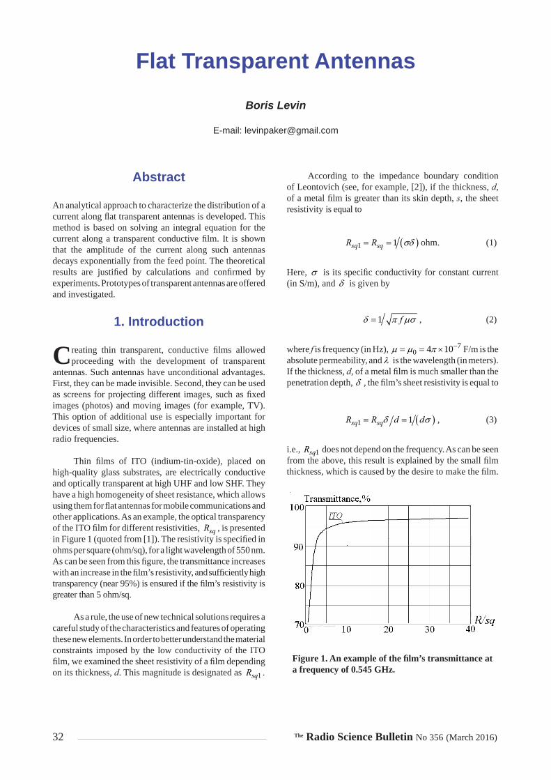
32 The Radio Science Bulletin No 356 (March 2016)
Boris Levin
E-mail: [email protected]
Flat Transparent Antennas
Abstract
An analytical approach to characterize the distribution of a current along fl at transparent antennas is developed. This method is based on solving an integral equation for the current along a transparent conductive fi lm. It is shown that the amplitude of the current along such antennas decays exponentially from the feed point. The theoretical results are justifi ed by calculations and confi rmed by experiments. Prototypes of transparent antennas are offered and investigated.
1. Introduction
Creating thin transparent, conductive fi lms allowed proceeding with the development of transparent
antennas. Such antennas have unconditional advantages. First, they can be made invisible. Second, they can be used as screens for projecting different images, such as fi xed images (photos) and moving images (for example, TV). This option of additional use is especially important for devices of small size, where antennas are installed at high radio frequencies.
Thin fi lms of ITO (indium-tin-oxide), placed on high-quality glass substrates, are electrically conductive and optically transparent at high UHF and low SHF. They have a high homogeneity of sheet resistance, which allows using them for fl at antennas for mobile communications and other applications. As an example, the optical transparency of the ITO fi lm for different resistivities, sqR , is presented in Figure 1 (quoted from [1]). The resistivity is specifi ed in ohms per square (ohm/sq), for a light wavelength of 550 nm. As can be seen from this fi gure, the transmittance increases with an increase in the fi lm’s resistivity, and suffi ciently high transparency (near 95%) is ensured if the fi lm’s resistivity is greater than 5 ohm/sq.
As a rule, the use of new technical solutions requires a careful study of the characteristics and features of operating these new elements. In order to better understand the material constraints imposed by the low conductivity of the ITO fi lm, we examined the sheet resistivity of a fi lm depending on its thickness, d. This magnitude is designated as 1sqR .
According to the impedance boundary condition of Leontovich (see, for example, [2]), if the thickness, d, of a metal fi lm is greater than its skin depth, s, the sheet resistivity is equal to
1 1sq sqR R ohm. (1)
Here, is its specifi c conductivity for constant current (in S/m), and is given by
1 f , (2)
where f is frequency (in Hz), 70 4 10 F/m is the
absolute permeability, and is the wavelength (in meters). If the thickness, d, of a metal fi lm is much smaller than the penetration depth, , the fi lm’s sheet resistivity is equal to
1 1sq sqR R d d , (3)
i.e., 1sqR does not depend on the frequency. As can be seen from the above, this result is explained by the small fi lm thickness, which is caused by the desire to make the fi lm.
Figure 1. An example of the fi lm’s transmittance at a frequency of 0.545 GHz.
The Radio Science Bulletin No 356 (March 2016) 33
The resistivity of ITO fi lm is substantially greater than the resistivity of printed cards and metal antennas, where copper and aluminum are used. For example, the sheet resistivity, 1sqR , of the transparent fi lm CEC005P is equal to 4.5 ohm/sq. The specifi c conductivities of copper and aluminum are, respectively, 75.8 10 S/m and
73.5 10 S/m. In accordance with Equations (1) and (2), the sheet resistivities of a copper plate with a thickness greater than the penetration depth at frequencies of 1 GHz and 5 GHz are hence equal to 36.9 10 and 318.4 10, respectively (the sheet resistivities of an aluminum plate with an analogous thickness at these frequencies are equal to 34.2 10 and 311.1 10 , respectively). The sheet resistivity of an ITO transparent fi lm is therefore greater by several orders of magnitude than the sheet resistivity of copper and aluminum, i.e., the conductive fi lms are different from materials (copper, aluminum) commonly used in antennas by having signifi cantly decreased conductivity, which changes the properties of radiators.
For a comparative analysis of antennas made of materials with high and low conductivity, it is necessary to apply methods for solving the corresponding boundary-value problems of electrodynamics. These methods are divided into direct numerical and approximate analytical methods. The conclusions made by specialists in the results of the application of these methods in prolonged research were clearly formulated in [3]: the undoubted advantage of analytical methods is that they are physically more visual in comparison with the numerical methods. The analytical methods allow determining the effect of the device’s parameters on its separate characteristics.
2. Current Distribution Along Radiator
In recent years, transparent antennas have been the subject of many works [4-6]. However, these works were devoted only to the defi nition and improvement of the characteristics of the materials. As a rule, the physical processes in transparent antennas, their electrical characteristics, and their differences from the characteristics of metal antennas with a high conductivity were not considered.
Knowledge of the current-distribution law along the antenna’s axis has a great importance in understanding the different physical processes in antennas. This knowledge allows defi ning all the main characteristics of the antennas. The determination of this law is therefore the basic problem in an analysis of any antenna. This postulate remains valid in spite of the elaboration of numerical programs such as CST; fi rst, since in the main these programs allow the calculation of the input characteristics of antennas (and characteristics dependent on them). The calculation of the current distribution by means of these programs is a diffi cult problem. Second, such programs do not allow one to know
the reason behind an obtained current distribution, and do not permit users to take into account those factors or features for use in the design of their antennas. Unfortunately, the characteristics of the current distribution along transparent antennas have not even been considered in the papers published so far.
Let us write an equation for the current in a fl at antenna in accordance with the integral equation for the current in a cylindrical antenna with nonzero (impedance) boundary conditions. In the case of a metal antenna this equation is valid if resistors are connected along the antenna or the metal cylinder has a low conductivity. If its surface impedance (resistance per unit of the antenna area) is large enough, then this impedance changes the antenna’s current distribution and the propagation constant of the wave along the antenna, already in the fi rst approximation. Similarly, in the case of a fl at transparent antenna with great losses, it is necessary fi rst of all to take into account the surface impedance. In the case of a transparent antenna, the surface impedance is equal to 1sqZ R . The width of a fl at transparent antenna can be taken into account afterwards, since the antenna’s width has a smaller effect on the antenna’s characteristics.
The integral equation for the current, J z , in a cylindrical impedance antenna was written for the fi rst time in [7] and solved in [8]. It has the form
2
22
d J zk J z
dz
4 ,2
Zj K z W J z J za
,
0J L . (4)
Here, z is the coordinate along the antenna’s axis; 2k is the propagation constant along a perfectly conducting metal surface; is the circular frequency; 0r is the absolute permittivity of a surrounding medium ( 0 is the absolute permittivity of the air, r is the relative permittivity of a medium, which in the case of a transparent antenna takes the substrate into account); is a small parameter of the thin-antenna theory ( 1 , where is the parameter used by Hallén: see [9]); K z e z is the impressed (extraneous) fi eld; ,W J z is an integral term, caused by radiation; Z is the surface impedance; and а is the radius of cylindrical antenna.
Equation (4) is solved by the perturbation method, i.e., the solution is sought as a series in powers of the small parameter (or in inverse powers of the large parameter ):

34 The Radio Science Bulletin No 356 (March 2016)
21 2 ...J z J z J z . (5)
The series converges if is rather small and the parameter is rather large. Substituting Equation (5) into Equation (4) and equating coeffi cients of the same powers of , as usual we come to a set of differential equations and boundary conditions. If 2Z a is of the same order as 1 , the surface impedance affects the current distribution along the antenna in the fi rst approximation, and the equation for 1J z can be written in the form
2
1 21 12 4 ,
d J zJ z j K z W J z
dz ,
1 0J L . (6)
Here, 2 2 2k j Z a .
In the case of a transparent antenna, the radiator is a thin rectangular plate (not a circular cylinder). A long impedance line, which is equivalent to a symmetrical radiator (dipole), is shown in Figure 2. An infi nitesimal element, dz , of the line comprises inductance 1d dz and capacitance 1dC C dz (here, 1 and 1C are the inductance and capacitance per unit length), and also the additional resistance 2Zdz a . From Equation (6), it follows that the propagation constant along the transparent antenna is a complex quantity that is equal to
2 2k j , (7)
where 2 Z a .
F r o m E q u a t i o n ( 7 ) , 2 2 20 exp j k
i . e . , 0 exp j , w h e r e 4 4 20 k
1 20.5 tan k , 20 18 f R b .
We write the current distribution in the form of
1
1
sin0
sinL z
J z JL
, (8)
and represent the numerator as an imaginary component of the exponential function
0 0sin Imexpj je L z j e z L
0 0Imexp cos sinj z L z L ,
i.e.,
1sin L z
0 0exp sin sin cosz L L z .
Similarly,
1 0 0sin exp sin cosL L L ,
i.e.,
00
0
sin cos0 exp sin
sin cosL z
J z J zL
(9)
This expression means that the current along the antenna’s axis is distributed over a sinusoidal law, with a propagation constant 1 0 cos , and an exponential decay of the amplitude with the decrement (the rate of decrease)
0 sin :
1
1
sin0 exp
sinL z
J z J zL
. (10)
Accordingly, the reactance of the antenna constructed with a transparent fi lm is equal toFigure 2. The impedance long line.

The Radio Science Bulletin No 356 (March 2016) 35
1cotA A eX W L , (11)
where
21 1 1 0 1 2A sq rW j R j C W jb k
Here, 2eL is the length of the radiating segment at the end of which the antenna current decreases to zero, and 0W is the wave impedance of a metal antenna with the same dimensions. The radiation resistance is equal to
2 2140 eR h , (12)
where 11
1 tan 2e eh L
is the effective length of the antenna.
The analysis performed led to an important conclusion. From Equations (9) and (10) it followed that the length of the radiating segment of the antenna is inversely proportional to and, in a fi rst approximation, is independent of frequency. This means that increasing the antenna length for operation at lower frequencies is useless.
For transition from a cylindrical to a fl at antenna, it is also necessary to calculate the parameter 1 , which defi nes the magnitude of W, and to replace a in Equation (7) by the plate width, b. An equivalent long line helps to reveal the physical meaning of the small parameter . For a linear antenna, this parameter is equal to 4rC . Here,
rC is the capacitance per unit length of the antenna, which
for the cylindrical antenna is equal to the self-capacitance of an infi nitely long wire located at a distance 2L from the surface of zero potential (L is the length of the antenna’s arm). In the case of the circular cylindrical antenna, the capacitance is equal to 2 lnrC L a , i.e., the small parameter is 0.5 ln 2L a .
In order to determine the parameter 1 for the fl at antenna, it is necessary to replace the self-capacitance per unit length of a cylinder by the self-capacitance, 1rC , of a plate (see [10]):
1 11 8rC sh L b L b sh b L ,
if 1 2 10L b , and
1 2 ln 2.4rC L b ,
if 2 10L b .
3. Experimental Study of Transparent Antenna
In accordance with the theoretical results, the manufactured model of the antenna had a small height (Figure 3, dimensions are given in mm). The radiator was made from the CEC005P fi lm. Assuming that the frequency was equal to 95 10f GHz, in
Figure 3a. A front view of the fl at transparent antenna. 1: transparent fi lm, 2: metal triangle, 3: glass substrate, 4: soldering point, 5: connector, 6: cable, 7: disk (dimensions are given in mm).
Figure 3b. A cross section of the fl at transparent antenna. 1: transparent fi lm, 2: metal triangle, 3: glass substrate, 4: soldering point, 5: connector, 6: cable, 7: disk (dimensions are given in mm).

36 The Radio Science Bulletin No 356 (March 2016)
accordance with the above formulas we obtained:1 0.36 2284m , 1 k , 11.4m , 0AW W
The calculated curves for the active and reactive components of the antenna input impedance are given in Figure 4. Experimental values are accordingly given by circles and triangles. During measurement, the model was mounted on a metal disk with a diameter of 0.5 m (Figure 5).
The exponential decay of the current along an antenna means that the signal is created by an antenna segment of length 2 that is adjacent to the feed point, and the current is virtually absent in the rest of the antenna. The input impedance of such an antenna therefore does not have a sharp resonance, and the effective length of the antenna is small.
In order to improve the matching of the transparent antenna with a cable and to raise the antenna’s effi ciency, a metal triangle with a width equal to the width of the radiator was connected to the radiator’s base, as shown in Figure 3. This triangle permitted creating a uniform current distribution across the whole width of the antenna. That increased the total current of the antenna and its radiated signal. The triangular segment of the described model was constructed as a printed circuit. However, the experiment showed that it could be made from the same CEC005P fi lm. The experimental characteristics of this model are presented in Figure 6 (refl ectivity), Figure 7 (standing-wave ratio), and Figure 8 (vertical signal in the plane of antenna and in the perpendicular direction). The antenna’s directional patterns in the horizontal and vertical plane are given in Figure 9. The results of the measurements showed
that this model had stable and rather high characteristics in the frequency range of 2.5 GHz to 4.5 GHz and higher.
Additional experiments were made in order to be convinced that increasing the antenna’s length for operation at lower frequencies was ineffective. These experiments were carried out on the model of the antenna (Figure 10a), created by its developers for operation at a frequency of 0.5 GHz. The model consisted of a transparent plate, 1, and a metal pad, 2. The plate was a fl at rectangular glass substrate, coated with a thin fi lm of indium-tin-oxide. The model was placed on a metal disc, 3. Compared to the wavelength (0.6 m in free space), the size of the plate
Figure 4. The input impedance of a fl at transpar-ent antenna.
Figure 5. A model of the antenna on the disk.
Model Structure Field (dB)
1 vertical fi lm –312 horizontal fi lm –37.53 pad only –40
Table 1. The Measured fi elds of three models.
Figure 6. The refl ectivity of the antenna model with a transparent triangle.
Figure 7. The standing-wave ratio of the antenna model with a transparent triangle.
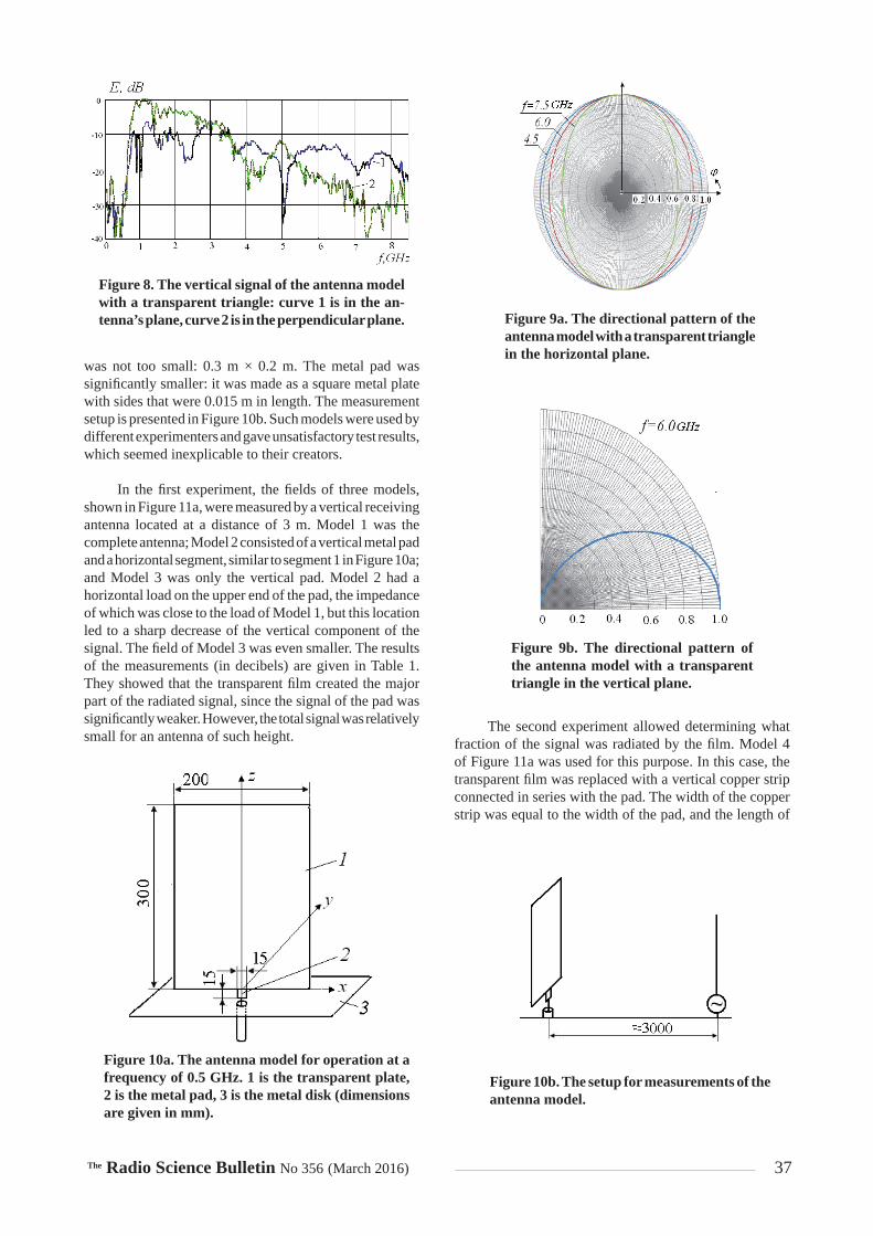
The Radio Science Bulletin No 356 (March 2016) 37
was not too small: 0.3 m × 0.2 m. The metal pad was signifi cantly smaller: it was made as a square metal plate with sides that were 0.015 m in length. The measurement setup is presented in Figure 10b. Such models were used by different experimenters and gave unsatisfactory test results, which seemed inexplicable to their creators.
In the fi rst experiment, the fi elds of three models, shown in Figure 11a, were measured by a vertical receiving antenna located at a distance of 3 m. Model 1 was the complete antenna; Model 2 consisted of a vertical metal pad and a horizontal segment, similar to segment 1 in Figure 10a; and Model 3 was only the vertical pad. Model 2 had a horizontal load on the upper end of the pad, the impedance of which was close to the load of Model 1, but this location led to a sharp decrease of the vertical component of the signal. The fi eld of Model 3 was even smaller. The results of the measurements (in decibels) are given in Table 1. They showed that the transparent fi lm created the major part of the radiated signal, since the signal of the pad was signifi cantly weaker. However, the total signal was relatively small for an antenna of such height.
The second experiment allowed determining what fraction of the signal was radiated by the fi lm. Model 4 of Figure 11a was used for this purpose. In this case, the transparent fi lm was replaced with a vertical copper strip connected in series with the pad. The width of the copper strip was equal to the width of the pad, and the length of
Figure 8. The vertical signal of the antenna model with a transparent triangle: curve 1 is in the an-tenna’s plane, curve 2 is in the perpendicular plane. Figure 9a. The directional pattern of the
antenna model with a transparent triangle in the horizontal plane.
Figure 9b. The directional pattern of the antenna model with a transparent triangle in the vertical plane.
Figure 10a. The antenna model for operation at a frequency of 0.5 GHz. 1 is the transparent plate, 2 is the metal pad, 3 is the metal disk (dimensions are given in mm).
Figure 10b. The setup for measurements of the antenna model.

38 The Radio Science Bulletin No 356 (March 2016)
the copper strip was chosen so that the signals radiated by Models 1 and 4 had equal values. The measurements showed that in this case, the total height of Model 4 had to be 0.09 m. Since Model 4 was a uniform monopole, it allowed determining the contribution of each part to the overall radiated signal. Assuming that the current along the monopole in the fi rst approximation was linearly distributed (Figure 11b), one could calculate that the entire effective length of the antenna was 0.045 m, and the effective lengths of the pad and the transparent fi lm were 0.0137 m and 0.0313 m, respectively. This meant that the transparent fi lm radiated 70% of the signal.
The results of the analysis of the current distribution along the antenna in Section 2 made it possible to approximately determine the length of the radiating segment of the model shown in Figure 10a. The resistivity of the losses in the transparent fi lm led to an exponential decay of the signal with a decrement . Additional attenuation was caused by the proximity of the substrate with dielectric permittivity r j . As shown in [11], the equivalent dielectric permittivity of the medium surrounding the
film is equal to 1 2 1 2e e A , where1 1 10A h b , and h and b are the thickness and width
of the substrate. Additional losses are caused by refl ection on a boundary between the plate and the pad. As a result, an approximate calculation showed that the length of the radiating segment was close to 10 cm, which corresponded to the results of the second experiment.
As has been said already, the total signal of Model 1 was relatively small for an antenna of such height. Considerations such as were made in Section 2 showed that the reason for this fact was a rapid decay of the current along the antenna’s axis. In order to confi rm this assumption, we compared two radiators of the same shape and dimensions (Figure 12a). One radiator was made from the CEC005P fi lm, and the other radiator was made from metal with perfect conductivity. Figure 12b shows the distribution of the current, J z , along these radiators, calculated by means of the program CST. The curve for the current along the metal antenna is denoted by the number 1, while the curve for the current along the transparent antenna is
Figure 11a. Experimental models for operation at a frequency of 0.5 GHz. Figure 11b. The effective length of the antenna.
Figure 12a. The model with a length of 0.32 m.
Figure 12b. The simulated current distributions at a frequency of 5 GHz along the axes of the metallic model (curve 1) and of the model with an indium-tin-oxide fi lm (curve 2).
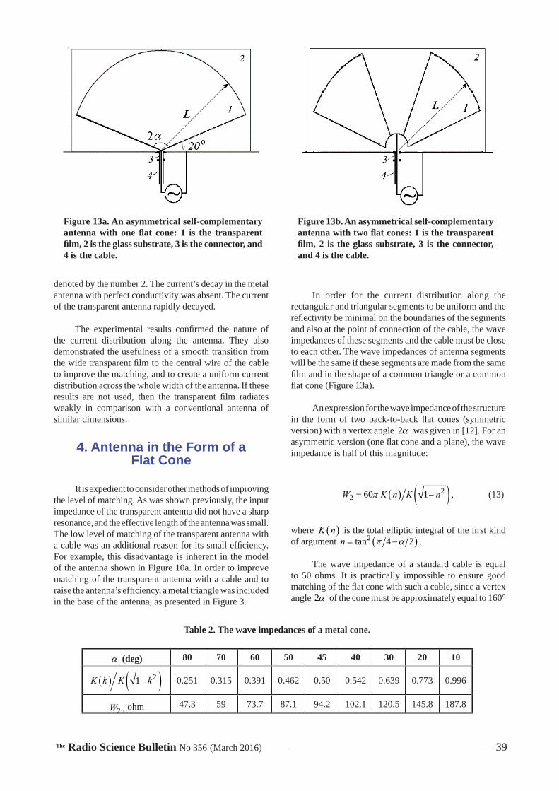
The Radio Science Bulletin No 356 (March 2016) 39
denoted by the number 2. The current’s decay in the metal antenna with perfect conductivity was absent. The current of the transparent antenna rapidly decayed.
The experimental results confi rmed the nature of the current distribution along the antenna. They also demonstrated the usefulness of a smooth transition from the wide transparent fi lm to the central wire of the cable to improve the matching, and to create a uniform current distribution across the whole width of the antenna. If these results are not used, then the transparent fi lm radiates weakly in comparison with a conventional antenna of similar dimensions.
4. Antenna in the Form of aFlat Cone
It is expedient to consider other methods of improving the level of matching. As was shown previously, the input impedance of the transparent antenna did not have a sharp resonance, and the effective length of the antenna was small. The low level of matching of the transparent antenna with a cable was an additional reason for its small effi ciency. For example, this disadvantage is inherent in the model of the antenna shown in Figure 10a. In order to improve matching of the transparent antenna with a cable and to raise the antenna’s effi ciency, a metal triangle was included in the base of the antenna, as presented in Figure 3.
In order for the current distribution along the rectangular and triangular segments to be uniform and the refl ectivity be minimal on the boundaries of the segments and also at the point of connection of the cable, the wave impedances of these segments and the cable must be close to each other. The wave impedances of antenna segments will be the same if these segments are made from the same fi lm and in the shape of a common triangle or a common fl at cone (Figure 13a).
An expression for the wave impedance of the structure in the form of two back-to-back fl at cones (symmetric version) with a vertex angle 2 was given in [12]. For an asymmetric version (one fl at cone and a plane), the wave impedance is half of this magnitude:
22 60 1W K n K n , (13)
where K n is the total elliptic integral of the fi rst kind of argument 2tan 4 2n .
The wave impedance of a standard cable is equal to 50 ohms. It is practically impossible to ensure good matching of the fl at cone with such a cable, since a vertex angle 2 of the cone must be approximately equal to 160°
Figure 13a. An asymmetrical self-complementary antenna with one fl at cone: 1 is the transparent fi lm, 2 is the glass substrate, 3 is the connector, and 4 is the cable.
Figure 13b. An asymmetrical self-complementary antenna with two fl at cones: 1 is the transparent fi lm, 2 is the glass substrate, 3 is the connector, and 4 is the cable.
(deg) 80 70 60 50 45 40 30 20 10
21K k K k 0.251 0.315 0.391 0.462 0.50 0.542 0.639 0.773 0.996
2W , ohm 47.3 59 73.7 87.1 94.2 102.1 120.5 145.8 187.8
Table 2. The wave impedances of a metal cone.

40 The Radio Science Bulletin No 356 (March 2016)
in order for the antenna’s wave impedance to be equal to the cable’s wave impedance (see Table 2). This will cause a sharp increase of spurious currents between the antenna’s edges and the ground.
As was shown in [13], the wave impedance of a self-complementary antenna depends on the number of metal radiators therein, and from the circuit of connection of these radiators to poles of the generator. If an antenna comprised of two metal radiators (monopoles) connected with each other with an angular width of 45° is used (Figure 13b), its wave impedance is equal to 15 (47 ohms). By adjusting the angular width of each radiator, one can provide exact equality of wave impedances of the antenna and the cable. In Figure 14, the refl ectivity of three antennas are compared with each other: the refl ectivity of an antenna with a triangular segment (curve 1: this refl ectivity is presented in Figure 6); the refl ectivity of an antenna with one transparent cone (curve 2: the length, L, of the arm is equal to 0.045 m); and the refl ectivity of an antenna with two transparent cones (curve 3: the arm length is also equal to 0.045 m). As is seen from Figure 14, the antenna with two metal radiators provided a smooth change of refl ectivity over a wide frequency range.
This result showed the signifi cant advantage of the antenna embodiment in the shape of a self-complementary radiator with one or two fl at cones.
5. Conclusion
The analytical and experimental study of a transparent fl at antenna, made of indium-tin-oxide fi lm, placed on a high-quality glass substrate, showed that its characteristics signifi cantly differed from the characteristics of both thin and wide conventional metal antennas. These differences were due to the fact that the low conductivity of the radiator led to an exponential decay of the current along
the antenna’s axis, and to a substantial shortening of the length of the radiating segment in comparison with the antenna’s length. As a result, the antenna’s effectiveness drastically decreased. If using the existing fi lms, it is impossible to create an effective antenna for operation at frequencies below 1 MHz. At frequencies above 1 MHz, a rather effi cient antenna can be created if it is designed as a self-complementary antenna in the shape of one or two fl at cones, or in the shape of a wide plate with a triangular transition to the central wire of the cable.
6. References
1. N. Guan et al., “Antennas Made of Transparent Conductive Films,” PIERS Online, 4, 1, 2008, pp. 116-120.
2. B. M. Levin, The Theory of Thin Antennas and Its Use in An-tenna Engineering, Sharjah, UAE, Bentham Science Publishers, 2013.
3. M. V. Nesterenko, “Analytical Methods in the Theory of Thin Impedance Vibrators,” Progress In Electromagnetics Research B, 21, 2010, pp. 299-328.
4. T. Peter et al., “A Novel Transparent UWB Antenna for Pho-tovoltaic Solar Panel Integration and RF Energy Harvesting,” IEEE Transactions on Antennas and Propagation, AP-62, 4, 2014, pp. 1844-1853.
5. J. Hautcoeur, F. Colombel, X. Castel, M. Himdi, and E. Motta
Cruz, “Optically Transparent Monopole Antenna with High Radiation Effi ciency Manufactured with Silver Grid Layer (AgGL),” Electronics Letters, 45, 20, 2009, pp. 1014-1016.
6. J. R. Saberin and C. Furse, “Challenges with Optically Trans-parent Patch Antennas,” IEEE Antennas and Propagation Magazine, 54, 3, June 2012, pp. 10-16.
7. M. A. Miller, “Application of Uniform Boundary Conditions to the Theory of Thin Antennas,” Journal of Technical Physics, 24, 8, 1979, pp. 1483-1495 (in Russian).
8. E. A. Glushkovsky, B. M. Levin, and E. Ya. Rabinovich, “In-tegral Equation for the Current in Thin Impedance Radiator,” Radiotechnics, 12, 1967, pp. 18-23 (in Russian).
9. C. A. Balanis, Antenna Theory: Analysis and Design, New York, Wiley & Sons, 2005.
10. Yu. Ya. Iossel, E. S. Kochanov, and M. G. Strunsky, Calcula-tion of Electrical Capacitance, Leningrad, Energoisdat, 1981 (in Russian).
11. M. V. Schneider, “Microstrip Lines for Microwave Integrated Circuits,” Bell System Technical Journal, 48, 5, 1969, pp. 1421-1444.
12. R. L. Carrel, “The Characteristic Impedance of Two Infi nite Cones of Arbitrary Cross Section,” IEEE
Transactions on Antennas and Propagation, AP-6, 2, 1958, pp. 197-201.
13. B. M. Levin, “Antennas with Rotational Symmetry,” Proceedings 10 International Conference on Antenna Theory and Techniques ICATT’15 (April 2015), Kharkiv, Ukraine, 2015, pp. 30-35.
Figure 14. The refl ectivity of the antennas with a transparent triangle (curve 1), with one trans-parent cone (curve 2), and with two transparent cones (curve 3).
The Radio Science Bulletin No 356 (March 2016) 41
XXXIInd General Assembly and Scientifi c Symposium ofthe International Union of Radio Science
Union Radio Scientifi que InternationaleAugust 19-26, 2017 Montréal, Québec, Canada
Announcement and Call for Papers
The XXXIInd General Assembly and Scientifi c Symposium (GASS) of the International Union of Radio Science (Union Radio Scientifi que Internationale: URSI) will be in Montréal. The XXXIInd GASS will have a scientifi c program organized around the ten Commissions of URSI, including oral sessions, poster sessions, plenary and public lectures, and tutorials, with both invited and contributed papers. In addition, there will be workshops, short courses, special programs for young scientists, a student paper competition, programs for accompanying persons, and industrial exhibits. More than 1,500 scientists from more than 50 countries are expected to participate. The detailed program, the link to the electronic submission site for papers, the registration form, the application for the Young Scientists program, and hotel information are available on the GASS Web site: http://www.gass2017.org
Submission Information
All papers should be submitted electronically via the link provided on the GASS Web site: http://www.gass2017.org. Please consult the symposium Web site for the latest instructions, templates, and sample formats. Accepted papers that are presented at the GASS may be submitted for posting to IEEE Xplore if the author chooses.
Important Deadlines: Paper submission: January 30, 2017Acceptance Notifi cation: March 20, 2017
Topics of Interest
Commission A: Electromagnetic Metrology Commission B: Fields and Waves Commission C: Radiocommunication and Signal Processing Systems Commission D: Electronics and Photonics Commission E: Electromagnetic Environment and Interference Commission F: Wave Propagation and Remote Sensing Commission G: Ionospheric Radio and Propagation Commission H: Waves in Plasmas Commission J: Radio Astronomy Commission K: Electromagnetics in Biology and Medicine
Young Scientists Program and Student Paper Competition
A limited number of awards are available to assist young scientists from both developed and developing countries to attend the GASS. Information on this program and on the Student Paper Competition is available on the Web site.
Contact
For all questions related to paper submissions for the GASS, please contact the URSI Secretariat: [email protected] all questions related to registration and attendance at the GASS, please see the GASS2017 Web site:
www.gass2017.org

42 The Radio Science Bulletin No 356 (March 2016)
AWARDS FOR YOUNG SCIENTISTSCONDITIONS
A limited number of awards are available to assist young scientists from both developed and developing countries to attend the General Assembly and Scientifi c Symposium of URSI.
To qualify for an award the applicant:
1. must be less than 35 years old on September 1 of the year (2017) of the URSI General Assembly and Scientifi c Symposium;
2. should have a paper, of which he or she is the principal author, submitted and accepted for oral or poster presentation at a regular session of the General Assembly and Scientifi c Symposium.
Applicants should also be interested in promoting contacts between developed and developing countries. Applicants from all over the world are welcome, including from regions that do not (yet) belong to URSI. All successful applicants are expected to participate fully in the scientifi c activities of the General Assembly and Scientifi c Symposium. They will receive free registration, and fi nancial support for board and lodging at the General Assembly and Scientifi c Symposium. Limited funds will also be available as a contribution to the travel costs of young scientists from developing countries.
The application needs to be done electronically by going to the same Web site used for the submission of abstracts/papers via http://www.gass2017.org. The deadline for paper submission for the URSI GASS2017 in Montréal is 30 January 2017.
A Web-based form will appear when applicants check “Young Scientist paper” at the time they submit their paper. All Young Scientists must submit their paper(s) and this application together with a CV and a list of publications in PDF format to the GA submission Web site.
Applications will be assessed by the URSI Young Scientist Committee taking account of the national ranking of the application and the technical evaluation of the abstract by the relevant URSI Commission. Awards will be announced on 1 May 2017 on the URSI Web site.
For more information about URSI, the General Assembly and Scientifi c Symposium and the activities of URSI Commissions, please look at the URSI Web site at: http://www.ursi.org and the GASS 2017 Web site at http://www.gass2017.org.
If you need more information concerning the Young Scientist Program, please contact:
The URSI SecretariatGhent University/INTEC
Technologiepark-Zwijnaarde 15B-9052 Gent
BelgiumE-mail: [email protected]

The Radio Science Bulletin No 356 (March 2016) 43
Ethically Speaking
Randy L. HauptColorado School of MinesBrown Building 2491510 Illinois Street, Golden, CO 80401 USATel: +1 (303) 273 3721E-mail: [email protected]
Stressing Ethics
Stress impacts our ethics. If our ethical armor is brittle, like plastic, then it cracks under the right amount of
stress. Our ethics should be resilient when challenged. We often don’t know how strong our ethics are until we are tested – which seems to happen too often, today. Our lives are stressful: not only do we have many of the same problems as our parents did only a generation ago, but we also have too much information for the brain to properly process. Our ethics are our fort against the marauding circumstances of daily life. We need strong ethics. In this missive, I divide stress into two types: emotional and competitive. Both types lower our resistance to fi ght off temptations to break our ethics, but in different ways. I am not a psychologist, so take my thoughts with a grain of salt.
Emotional stress occurs when something bad happens to us. For instance, a year ago, my father died at 88 years old, after struggling with dementia and leukemia. I had a wonderful conversation with him the day before he passed away. Becoming an orphan at 58 years old is more diffi cult on Earth than it would be on the planet Vulcan. I didn’t realize at the time how vulnerable I was. The stress associated with his death disrupted my concentration from other parts of my life. Friends and family help when working through grief. They shield you from the wolves that try to isolate you from the herd before attacking.
Job loss is another high-stress situation. Losing your job often comes unexpectedly, with no time to prepare. Slashing out at people is very tempting. Withdrawal is common. Some friends quickly disappear when you lose
your job. The resulting isolation and depression debilitates the best of us. Keeping active and fi nding positive outlets are very important. You must keep the wolves at bay.
Competitive stress results when we vie to win a contest. This type of stress actually helps counter emotional stress, and is often associated with a healthy lifestyle. I remember when I used to run races: the adrenaline fl owed higher, the closer the time came for the start. When the gun went off, it was hard not to sprint, even when the race was a marathon. You can even get euphoric (high) from intense exercise. This type of stress occurs in the workplace as well: meeting deadlines, fi nishing papers and proposals, and competing for an award. There is a thrill in the competition that can tempt us to forget our ethics. Although competitive stress seems good, it can have a negative effect on our ethics by infl ating our egos. It is easy to trample other people during the heat of battle. We forget to thank others when we win. We take it out on people when we lose. Egos have successfully trampled ethics throughout history.
These two completely different forms of stress chip
away at ethical behavior. How do you prevent this stress attack on your ethics? Talking with friends, meditating, praying, reading helpful literature, etc., help you to handle the tough times. In other words, be prepared. Another step is to be aware of yourself and your environment. Learn to sense when you are under a lot of stress, and then take steps to adjust. I doubt that our world will get less stressful. My hope is that we will all take steps to b uild a powerful ethical defense against this enemy.

44 The Radio Science Bulletin No 356 (March 2016)
Randy L. Haupt received the BSEE from the US Air Force Academy (1978), the MS in Engineering Management from Western New England College (1982), the MSEE from Northeastern University (1983), and the PhD in Electrical Engineering from the University of Michigan (1987). He is Professor of Electrical Engineering and Computer Science at the Colorado School of Mines. He was an RF Staff Consultant at Ball Aerospace & Technologies, Corp.; a Senior Scientist and Department Head at the Applied Research Laboratory of Penn State; Professor and Department Head of ECE at Utah State; Professor and Chair of EE at the University of Nevada Reno; and Professor of EE at the USAF Academy. He has taught courses on
Introducing Randy L. Haupt,Associate Editor for Ethically Speaking
ethics for engineers at several of these universities. He was a project engineer for the OTH-B radar, and a research antenna engineer for Rome Air Development Center, early in his career. He was coauthor of the books Practical Genetic Algorithms, Second Edition, (John Wiley & Sons, 2004), Genetic Algorithms in Electromagnetics (John Wiley & Sons, 2007), and Introduction to Adaptive Antennas (SciTech, 2010). He was author of Antenna Arrays: A Computation Approach (John Wiley & Sons, 2010) and Timed Arrays Wideband and Time-Varying Antenna Arrays (Wiley, 2015). Dr. Haupt is a Fellow of the IEEE and of the Applied Computational Electromagnetics Society (ACES). He is Chair of the IEEE AP-S Fellows Committee.

The Radio Science Bulletin No 356 (March 2016) 45
Giuseppe PelosiDepartment of Information EngineeringUniversity of FlorenceVia di S. Marta, 3, 50139 Florence, ItalyE-mail: giuseppe.pelosi@unifi .it
Historical Column
A Fermi You Did Not Expect: His “Perfect Gas” Marks the Electronics Dawn
Roberto Casalbuoni
Department of Physics and AstronomyUniversity of Florence, Via Sansone &, I-50019 Sesto Fiorentino, Florence, Italy
E-mail: casalbuoni@fi .infn.it
Ninety years ago, on February 7, 1926, Antonio Garbasso (1871-1933), Director of the Institute of Physics and
Mayor of the city of Florence, presented a paper by Enrico Fermi (1901-1954) entitled, “On the Quantization of the Perfect Monoatomic Gas” [1]. This was for publication in the Proceedings of the Lincei National Academy. This work was fundamental in various fi elds of physics, and in many technology applications that we use in our everyday life.
Fermi graduated from the Scuola Normale Superore in Pisa [2] in July 1922. Going back to Rome, his own hometown, he met Orso Mario Corbino (1876-1937), Director of the Institute of Physics. Corbino immediately recognized Fermi’s great scientifi c value, and in 1923, pushed him to travel to Göttingen, in Germany, one of the world’s important theoretical-physics centers. From October to December of 1924, Fermi went to Leiden, invited by Paul Ehrenfest (1880-1933), a famous theoretical physicist of that time. From January 1925, Fermi obtained the position of Professor of Mathematical Physics in Florence. He remained there until 1926, when in Rome he won the fi rst Italian Chair of Theoretical Physics.
Bruno Pontecorvo wrote about Fermi’s stay in Florence in the following terms [3]: The Florentine period was very important in the life
of Fermi. In Florence he met again Rasetti, who was assistant of Garbasso, and performed with him some original experiment....But the most important thing was that, right there, in the quiet atmosphere of the physical institute, located on the hill where Galileo died, Fermi wrote and published his famous work on the statistical
Figure 1. Enrico Fermi and some friends around the well in the cloister of the Institute of Physics in Florence. (front, l-r) Franco Rasetti, Nello Carrara (1900-1993), and Enrico Fermi. Rita Brunetti (1890-1943) is in back.

46 The Radio Science Bulletin No 356 (March 2016)
mechanics of particles subjected to the principle of Pauli.”
Rasetti (1901-2001) had been a classmate of Fermi at the University of Pisa, and was a brilliant experimental physicist (see Figure 1). Another classmate was Nello Carrara, the researcher who introduced the word “microwaves” in the technical literature [4].
In his 1926 work, Fermi founds the law governing the statistical behavior of particles such as electrons, neutrinos, protons, neutrons, and quarks. Fermi initiated dealing with these problems in 1923, but their solution arrived only after Pauli (1900-1958) formulated the Exclusion Principle in January 1925. This principle, which refers to the electrons in an atom, says that these particles can not coexist in the same state. Fermi extended this principle, and the particles that obey it are called “fermions” after him.
Fermi’s result was independently obtained by Dirac (1902-1984) in a paper of August 26, 1926, using the Schrödinger wave mechanics formulated in January of the same year. Dirac did not mention Fermi’s work, but after receiving Fermi’s letter of claim, recognized his priority. In his work, Fermi evaluated the average number of fermions with a certain energy at a given temperature. This law goes under the name of the Fermi-Dirac distribution law.
Fermi’s work had almost immediate repercussions in various fi elds of physics. For example, in 1926, Ralph H. Fowler (1889-1944) applied it to astrophysics, and in February of 1927, Wolfgang Pauli applied it to electrons in metals. To understand the relevance of Fermi’s work, it is suffi cient to realize that about a dozen scientifi c terms derive from it, such as, for instance, taking apart Fermi-Dirac statistics and fermions, the Fermi surface, the Fermi momentum, the Fermi level, etc. [5].
However, Fermi’s work also has fundamental effects on our daily lives. In fact, our understanding of the physical behavior of semiconductors is due to this work, allowing the development of modern electronics. Bardeen (1908-1991) won the Nobel Prize in 1956 for his research on semiconductors and the transistor. In his speech for the award of the Prize began by quoting the law of distribution of Fermi-Dirac (see Figure 2). Bardeen was the only person to have received two Nobel prizes in Physics, the second one in 1972 for superconductivity, the theoretical aspects of which once again rely on the Fermi-Dirac distribution. It can thus be said that this law is the basis of micro- and nano-electronics, and therefore the basis for all electronic devices that we use today, starting from cell phones, computers, etc. It has also contributed to the development of technology that led to the production of photovoltaic energy.
Figure 2a. John Bardeen (1908-1991).
Figure 2b. The title and fi rst equation of John Bardeen’s Nobel lecture (1956)

The Radio Science Bulletin No 356 (March 2016) 47
In 2015, the IEEE (Institute of Electrical and Electronic Engineers) recognized the outstanding contribution of Enrico Fermi to modern technology through a plaque placed at the School of Engineering of the University of Florence [6] (Figure 3).
References and Notes
1. E. Fermi, “Sulla quantizzazione del gas perfetto monoatomico,” Atti dell’Accademia dei Lincei, 3, 3, 1926, pp. 145-149. An extended version was sent to Zeitschrift für Physik in March 1926.
2. Most of the information about Fermi came from his biography, written by his wife: L. Fermi, Atoms in the Family, Chicago, University of Chicago Press, 1954.
3. B. Pontecorvo, Fermi e la Fisica Moderna (Fermi and the Modern Physics), La Citta’ del Sole, 2004.
4. G. Pelosi, “The birth of the Term Microwaves,” Proceedings of IEEE, 84, 2, 1996, p. 326.
5. Fermi has made very important contributions in many fi elds of physics. There are more than 40 scientifi c terms referring to his name.
6. F. Manes and G. Pelosi (eds.), “Enrico Fermi’s IEEE Milestone in Florence,” Florence, Firenze University Press, 2015.
Please note that the URSI Secretariat
has moved to a new address
since15 March 2016:
URSI SecretariatGhent University - INTEC
Technologiepark-Zwijnaarde 15B-9052 GentBELGIUM
The telephone and fax number remain the same :Tel. : +32 9-264 3320Fax: +32 9-264 4288
Figure 3. The IEEE Milestone dedicated to Enrico Fermi at the School of Engineering of the University of Florence.
48 The Radio Science Bulletin No 356 (March 2016)
XXIst International Seminar/Workshop DIRECT AND INVERSE PROBLEMS OF ELECTROMAGNETIC
AND ACOUSTIC WAVE THEORY (DIPED-2016)
Tbilisi, Georgia, September 26-29, 2016
FIRST CALL FOR PAPERS
General Information The XXIst International Seminar/Workshop on Direct and Inverse Problems of Electromagnetic and Acoustic Wave Theory (DIPED-2016) will be held at the Tbilisi State University, Georgia, on September 26-29, 2016. The IEEE MTT/ED/AP/EMC Georgian and MTT/ED/AP/CPMT/SSC West Ukraine Chapters are co-organizers of the DIPED-2016. The DIPED seminar series was started in 1982, it began newly as the IEEE ED, MTT, and AP Societies technical co-sponsored event since 1995. Suggested Topics
Theoretical aspects of electrodynamics Waveguide and photonic crystal structures Diffraction theory Inverse problems and synthesis Propagation and scattering in complex media Antennas and antenna arrays Numerical methods in the electrodynamics Acoustics: theory and applications
Instruction for Authors 1. The instruction for preparing the papers will be presented in the Web Site of the DIPED-2016
Seminar/Workshop. 2. The WinWord doc or LaTeX files should be sent to Dr. Mykhaylo Andriychuk, Program Committee
Secretary, via e-mail [email protected]. Important Dates
August 1, 2016 Deadline for reception of camera-ready papers. August 15, 2016 Notifications of authors about acceptance of the papers. September 26-29, 2016 Seminar/Workshop DIPED-2016.
Organizing Committee
Chairman: Prof. Revaz S. Zaridze Ivane Javakishvili Tbilisi State University 3, Chavchavadze Ave. 0179, Tbilisi, Georgia Tel.: +995 32 2290 821, fax: +995 32 2290 845 e-mail: [email protected]
Secretary: Dr. Tamar Gogua Ivane Javakishvili Tbilisi State University 1, Chavchavadze Ave. 0179, Tbilisi, Georgia Tel: +995 32 2222 473, fax: +995 32 2222 473 E-mail: [email protected]
Program Committee
Chairman: Prof. Nikolai N. Voitovich Pidstryhach Institute for Applied Problems in Mechanics and Mathematics, NASU 3”B” Naukova St., Lviv, 79060, Ukraine Tel: +38 032 258 51 44, fax: +38 032 263-72-70 E-mail: [email protected]
Secretary: Dr. Mykhaylo Andriychuk Pidstryhach Institute for Applied Problems in Mechanics and Mathematics, NASU 3”B” Naukova St., Lviv, 79060, Ukraine Tel: +38 032 258 96 46, fax: +38 032 263-72-70 E-mail: [email protected]
For detailed information, please visit web site: http://www.ewh.ieee.org/soc/cpmt/ukraine/ or http://ewh.ieee.org/r8/ukraine/georgian/DIPED/

The Radio Science Bulletin No 356 (March 2016) 49
Telecommunications Health and Safety
James C. LinUniversity of Illinois at Chicago851 South Morgan Street, M/C 154Chicago, IL 60607-7053 USAE-mail: [email protected]
Public Expos ure to Radio Frequency, Microwave, and Millimeter-Wave
Electromagnetic Radiation
The current world population (total number of human beings living on Earth) is about 7.4 billion, according
to estimates by the United Nations Department of Economic and Social Affairs, Population Division [1]. Statistics and forecasts suggest the total number of mobile-phone users worldwide will reach 4.8 billion by 2017, and is expected to pass the 5 billion mark by 2019 [2]. In 2014, ownership of mobile phones reached 60% of the Earth’s population. Mobile-phone penetration is likely to continue to grow to 67% by 2019.
Mobile phones and other wireless devices and systems rely on radio-frequency (RF) or microwave radiation to function. They use RF or microwave radiation to send and receive messages, voice, and data. In addition to RF and microwaves, millimeter (mm) and terahertz (T) waves are increasingly enlisted to support the rally toward ubiquitous wireless connectivity, at any time.
Wireless applications of RF and microwave radiation are found nearly everywhere, including in the outdoor environment, on the street, inside public transportation, in and outside the home, in and around automobiles, and even on and inside human bodies. Besides mobile phones, wireless devices and gadgets show up as intelligent sensors, smart meters, and security monitors and controllers in homes, offi ces, factories, healthcare facilities, during workouts and sports activities, and supported by such platforms as the Internet of Things (IoT), among the latest.
Today, many healthcare providers rely on mobile information access and messaging tools to improve
communications, accessibility, and to enhance decision-making capabilities associated with the delivery of healthcare. Handhelds and “wearables” are commonly used for mobile tracking of fi tness activities, vital signs, or sleep research. They also are found in healthcare environments, along with implantable and ingestible medical devices with integrated RF antennas for wireless communication (telemetry), supported by remote monitoring and control functions in many diagnostic and therapeutic procedures to help improve healthcare delivery.
These applications and other uses are enabled by wireless technologies such as Wi-Fi, Bluetooth, and ZigBee, and underpinned by networks, routers, base stations, repeaters, and satellite systems operating in the RF and microwave ranges.
RF and microwave electromagnetic radiation is the
lifeblood of wireless systems. Once primarily an urban phenomenon in industrialized countries, the world in recent years has seen rapid growth in demand for wireless access, which is projected to continue for years to come. Meeting the demand will translate into greater human exposure to RF and microwave radiation. Not only for the fi rst time in its history, an ubiquitous source of RF radiation is placed right next to the head (and body) of a large fraction of the human race, the percentage of all humanity exposed to RF electromagnetic radiation is approaching polluted air. (In 2013, 87% of the world’s population lived in areas with pollution exceeding the World Health Organization Air Quality Guidelines [3]).

50 The Radio Science Bulletin No 356 (March 2016)
Scientifi c research on biological effects and health risks of RF radiation began in the 1940s, and guidelines for limiting exposure to RF electromagnetic fi elds were published in the 1960s, with the objective of providing protection against known adverse health effects. In the interim, guidelines were periodically revised and updated. Current guidelines in the RF range, for example, impose basic restrictions on specifi c-absorption-rate (SAR) limits on general public and occupational exposures to avoid whole-body heat stress and excessive localized tissue heating, specifi cally to prevent biological and health effects in responses to a body temperature rise of 1°C or more for an averaging time of six minutes [4, 5]. This level of temperature increase results from exposure of individuals under moderate environmental conditions to a whole-body SAR of approximately 4 W/kg for about 30 min. A whole-body average SAR of 0.4 W/kg was chosen as the restriction that provides adequate protection for occupational exposure. An additional reduction factor of fi ve was introduced for public exposure, giving an average whole-body SAR limit of 0.08 W/kg.
However, a waxing question persists on guidelines for safe long-term exposure to low-level RF radiation. There is a general sense about a lack of scientifi c knowledge regarding long-term human exposure below existing basic restrictions, lower than those for which there is an abundance of reliable data or evidence. Since the initial research investigations, there have been thousands of published scientifi c studies on RF biological effects and health risks. Many of them followed the introduction of mobile telephony, and were associated with it. A fair summary, regardless of their experimental design, quality, merits, limitations, fl aws, or methodological weakness, would suggest that there are more reported studies showing no effect than showing effect. However, few studies have been subjected to extant independent replication of results. The subject thus remains controversial, and there still is a lot of uncertainty, in part due to constraints on research funding, as government-funded RF biological effect science dwindled, especially in the US.
That said, since the late 2000s, a “secretive” fi ve-
year project was sole-sourced through a contract to IITRI in Chicago to investigate whether long-term exposure to cell-phone-type wireless RF radiation can cause cancer in rats and mice [6]. This project is the largest animal cancer study ever undertaken by the National Toxicology Program (NTP) and National Institute of Environmental Health Sciences (NIEHS), with a price tag of $25 million or more of US taxpayer money [7]. Although years overdue, with huge budget overruns, the project appears to have not yet been completed. (Note that the life spans of rats and mice are about two years.) Staff members at IITRI are mum about it. To date, in contrast to scientifi c norm, they have not discussed any results or made any presentations of their fi ndings at scientifi c meetings. NIEHS has refused to release any progress reports or project documents.
An international panel of experts convened by the
World Health Organization’s International Agency for
Research on Cancer (IARC) concluded in 2011 that exposure to RF electromagnetic fi elds, including those used by mobile phones, was “possibly carcinogenic” to humans [8]. The panel assessed available scientifi c papers and concluded that while evidence was incomplete and limited, published epidemiological studies reporting increased risks of 40% to 200% for gliomas (a type of malignant brain cancer) and acoustic neuromas (a nonmalignant tumor of the auditory nerve on the side of the brain) among heavy or long-term users of mobile phones were suffi ciently strong to support a classifi cation of possibly carcinogenic to humans for exposure to RF electromagnetic fi elds [9, 10].
Note that other scientific groups, such as the International Commission on Non-Ionizing Radiation Protection’s (ICNIRP) Standing Committee on Epidemiology [9], evaluating the same data or evidence, concluded that increased risk was entirely explicable by various biases or errors, believing that there was little possibility that mobile-phone use could increase risk of glioma or acoustic neuroma in users.
Nevertheless, Belgium responded by adopting new regulations to promote mobile-phone RF radiation safety, and banned the sale of mobile phones to children [11]. The French Health Agency recommended that children and vulnerable groups should take measures to reduce their mobile-phone RF exposure [12].
The US Federal Communications Commission (FCC) states that no scientifi c evidence currently establishes a defi nite link between wireless-device use and cancer or other illnesses, and that some parties have recommend taking measures to reduce exposure to RF energy from mobile phones [13]. While the FCC does not endorse the need for these practices, it provides information on some simple steps that can be taken to reduce personal exposure to RF radiation from mobile phones. For example, it notes wireless devices only emit RF energy when they are in use, and the closer the device is to user, the more RF energy is absorbed by the individual.
The US Federal Food and Drug Administration (FDA) advises, “if there is a risk from being exposed to RF radiation from mobile phones – and at this point FDA does not know that there is – it is probably very small.” However, if an individual is concerned about avoiding even potential risks, one can take a few simple steps to minimize RF exposure, such as reducing the amount of time spent using a mobile phone, and using speaker mode or a headset to place more distance between the head and the mobile phone [14].
Full recognition of a public health risk takes time. The paradigms of “An ounce of prevention is far better than a pound of cure” seems to have gone by the wayside years ago. It now often evokes strong responses, with momentous resistance from those who have profi ted from mass marketing.

The Radio Science Bulletin No 356 (March 2016) 51
Antibiotics save lives, and remain a vital tool in the fi ght against bacterial infection in modern medicine. However, antimicrobial resistance has become a major challenge. The number of bacterial pathogens that have become resistant to antibiotics is increasing as a result of wide-spread and inappropriate use of antibiotics in health care and food production. Today, some 70 years since Alexander Fleming’s Nobel Prize for discovery of penicillin and its curative effects in various infectious diseases in 1945 [15], too many of the hundreds of thousands of people who get infected worldwide with pathogens die each year, and much more needs to be done to curb inappropriate use of antibiotics.
Fleming had cautioned about antimicrobial resistance in his acceptance lecture by telling a story (and I paraphrase):
A Mr. X who suffers from a sore throat takes some penicillin. The dose is not suffi cient to eradicate the streptococci but enough to make them resistant to penicillin. His wife picks up the bug and she comes down with pneumonia. Mrs. X is treated then with this wonder drug, penicillin. As the streptococci are now resistant to penicillin, the treatment fails and unfortunately Mrs. X dies.
In 1986, IARC classifi ed active tobacco smoking as carcinogenic in humans, and announced that there was suffi cient evidence to conclude that tobacco smoking caused cancers not only of the lung, but also of the upper digestive tract including oral cavity, pharynx, larynx, and esophagus; pancreas; and lower urinary tract, including the bladder and renal pelvis [16].
However, evidence of the harm done by tobacco smoking had been accumulating for more than 200 years prior: at fi rst with regard to cancers of the lip and mouth, and then to vascular disease and cancer of the lung [17]. The evidence was generally ignored until several epidemiological studies linking smoking to the development of lung cancer were published in 1950. These studies stimulated more research, which, by the 1950s, was beginning to show that smoking was associated with lung cancer. That smoking was connected with lung cancer and various diseases was vigorously debated for many years, and general acceptance for lung cancer came only about by the late 1950s, and eventually for other diseases in the subsequent decades.
References
1. United Nations, “World Population,” United Nations Depart-ment of Economic and Social Affairs, Population Division, http://www.worldometers.info/world-population/, accessed in February 2016.
2. Statista, “Forecast of Mobile Phone Users Worldwide from 2013 to 2019,” http://www.statista.com/statistics/274774/forecast-of-mobile-phone-users-worldwide/, accessed in February 2016.
3. M. Brauer, G. Freedman, J. Frostad, A. van Donkelaar, R. V. Martin, F. Dentener, K. Estep, H. Amini, J. S. Apte, K. Balakrishnan, L. Barregard, D. Broday, F. Feigin, S. Ghosh, P. K. Hopke, L. D. Knibbs, Y. Kokubo, Y. Liu, S. Ma, L. Morawska, J. L. Sangrador, G. Shaddick, H. R. Anderson, T. Vos, M. H. Forouzanfar, R. T. Burnett, and A. Cohen, “ Ambient Air Pollution Exposure Estimation for the Global Burden of Disease 2013,” Environ. Sci. Technol., 50, 1, 2016, pp. 79-88.
4. International Commission on Non-Ionizing Radiation Protec-tion (ICNIRP), “Guidelines for Limiting Exposure to Time-Varying Electric, Magnetic, and Electromagnetic Fields (Up to 300 GHz),” Health Phys., 74, 1998, pp. 494-522.
5. Institute of Electrical and Electronic Engineers (IEEE), Stand-ard for Safety Levels with Respect to Human Exposure to Radio Frequency Electromagnetic Fields, 3 kHz to 300 GHz, New York, IEEE Press, 2005.
6. Microwave News, “Institute of Environmental Health Secrets: NIEHS Mum on $25 Million RF Animal Project,” http://www.microwavenews.com/news-center/ntp-rf-animal-studies, ac-cessed in February 2016.
7. J. C. Lin, “The Unusual Story of the IARC Working Group on Radio Frequency Electromagnetic Fields and Mobile Phones,” URSI Radio Science Bulletin, No. 338, 2011, pp. 54-55; J. C. Lin, “Reply to Letter to the Editor Regarding a Column by Dr. J. C. Lin,” URSI Radio Science Bulletin, No. 339, 2011, p. 6.
8. R. Baan et al. (on behalf of the WHO International Agency for Research on Cancer Monograph Working Group), “Car-cinogenicity of Radiofrequency Electromagnetic Fields,” The Lancet Oncology, 12, 7, 2011, pp. 624-626.
9. J. C. Lin, “Are Radio Frequency or Mobile Phone Electro-magnetic Fields Possibly Carcinogenic to Humans?”, URSI Radio Science Bulletin, No. 340, 2012, pp. 53-54.
10. J. C. Lin, “Mobile Phone Use and Brain Tumor Research,” URSI Radio Science Bulletin, No. 334, 2010, pp. 64-65.
11. PRELOG, “Belgium Adopts New Regulations to Promote Cell Phone Radiation Safety,” Berkeley, CA, October 25, 2013, https://www.prlog.org/12231532-belgium-adopts-new-regulations-to-promote-cell-phone-radiation-safety.html.
12. ANSES, Press Kit: “Update of the ‘Radiofrequencies and Health’ Expert Appraisal,” October 15, 2013, http://bit.ly/19MexVc.
13. FCC, “Wireless Devices and Health Concerns,” https://www.fcc.gov/consumers/guides/wireless-devices-and-health-concerns, accessed on February 21, 2016.
14. FDA, “Reducing Exposure: Hands-free Kits and Other Ac-cessories,” http://www.fda.gov/Radiation-EmittingProducts/RadiationEmittingProductsandProcedures/HomeBusines-sandEntertainment/CellPhones/ucm116293.htm, accessed on February 21, 2016.
15. A. Fleming, “Nobel Lecture: Penicillin,” in Nobel Lectures, Physiology or Medicine 1942-1962, Amsterdam, Elsevier Publishing Company, 1964.
16. IARC, “Tobacco Smoking,” IARC Monographs on the Evalu-ation of Carcinogenic Risks to Humans, 38, Lyon, France, IARC, 1986.
17. R. Doll, “Uncovering the Effects of Smoking: Historical Perspective,” Stat. Methods Med. Res., 7, 1998, pp. 87-117.

52 The Radio Science Bulletin No 356 (March 2016)

The Radio Science Bulletin No 356 (March 2016) 53
Women in Radio Science
Asta Pellinen-WannbergUmeå University, Department of Physics andSwedish Institute of Space Physics S-90187 Umeå, Sweden Tel: +46 90 786 7492 E-mail: [email protected]
Introduction from the Associate Editor
After a Christmas break, we are back with Women in Radio Science. This time I will present an old colleague of mine, Sheila Kirkwood, Professor of Atmospheric Physics, the leader of the Polar Atmospheric Research program at the Swedish Institute of Space Physics in Kiruna, and a Fellow of the Royal Swedish Academy of Sciences.
Sheila is a true scientist. She is interested in all kinds of phenomena in nature, details of basic physical concepts, various research topics, as well as vertical and horizontal hikes during all seasons. The only topic I have felt to be better at than she is cross-country skiing. She is very thorough in her scientifi c work, which expands over a broad range of topics. Through and thanks to this diversity, she early became a very successful scientist. Here, you can read her own story.
Refl ections on a Career in Radio ScienceSheila Kirkwood
Polar Atmospheric Research Swedish Institute of Space PhysicsBox 812, S-98128 Kiruna, Sweden
Tel. +46 980 79083E-mail: [email protected]
www: http://www.irf.se/paf
I suppose I have worked in “radio science” most of my career, although I haven’t really thought of it that way.
After an undergraduate degree in Geophysics and a PhD in Seismology, I started to work with the EISCAT Incoherent Scatter Radar system in 1980. EISCAT had just started delivering data, and it was fun to work with all the new observations of what is really happening in the northern lights: the focus was on the physics of the aurora, rather than the “radio science.” Since the 1990s, I have also worked with MST radars, both in the Arctic and Antarctica, but again the focus has been geophysics, not the technique. Workshops and conferences devoted to radio or radar techniques were so clearly get-togethers for the men that I never thought of myself as a radio scientist. However, I grew up with a burning curiosity to understand how our Earth works: how this tiny oasis in the galaxy
managed to nurture life and allow civilization to develop, and how it might change in the future. Combine this with a love of mathematics, physics, and climbing mountains, and obviously I became a geophysicist!
I have been fortunate in my career, from early encouragement by one of the very few senior women in geophysics in the 1970s, through a series of lucky breaks. I have been able to work in several fi elds of geophysics, at the same time as having a family. I was lucky to start university in 1970 at a time when computers were just starting to be used: when we still used punched cards to feed in the code, and the fast Fourier transform was a brand new research paper. Computers were easy for we young scientists to handle, so we were a welcome asset in the research groups. My next lucky break was to be fi nishing

54 The Radio Science Bulletin No 356 (March 2016)
a post-doc just at the time the EISCAT incoherent scatter radar was coming online (1981) and looking for a staff scientist. This gave me the chance to move to the mountains and the affordable childcare of northern Norway, and to apply the data-processing skills I had learned in seismology to a new fi eld: radio waves scattered from the Northern Lights. This job also gave me hands-on experience of radar hardware, and a taste for more in that direction. In 1987, I was able to move into full-time research at the Swedish Institute of Space Physics in Kiruna, where I have been ever since.
Starting out studying the aurora, I found that using radar to study the neutral atmosphere was less well developed, and I was able to move into that fi eld. I was fortunate to be able to fi nd research funding before the current fashion for channeling everything to only the biggest projects at the major universities. In a joint project with Swedish Space Corporation, we installed the fi rst MST radar at Esrange. This has been operating for 19 years now, and is the only radar of its type with such a long continuous record. In 2003, by a lucky chance, I heard that Sweden had a research station in Antarctica. This was fairly new and not yet over-subscribed – what they needed, I decided, was a small MST radar. We made it a moveable system, and it operated during four summer seasons at the Swedish station, Wasa, before being moved to the year-round Norwegian station, Troll, and then after two years to the Indian station, Maitri. For a scientist, work in Antarctica has the distinct advantage that there is a shortage of technical assistance, so you have to do the practical work yourself: much more fun than sitting in front of a computer all day!
So, how should I summarize my career? I have kept my eyes and ears open for opportunities where I could apply the skills I have to questions about our environment, in places I wanted to be. I have been happy to move, both geographically and in research fi elds. I have become a Professor, and have been able to give several young scientists – many of them women – a chance to try research as a lifestyle. I have been able to live and work surrounded by mountains, in the tranquility at the ends of the Earth.
Introd ucing the Author
Sheila Kirkwood is a Professor of Atmospheric Physics at the Swedish Institute of Space Physics in Kiruna, Sweden. She originally came from Scotland. She
Figure 1. A picture of Sheila Kirkwood
received her BSc in Geophysics and PhD in Seismology at Edinburgh University in the 1970s, and worked as Lecturer and Research Scientist in Physics at universities in Nigeria, Scotland, and England. In 1984, she got a staff scientist position at EISCAT Scientifi c Association, close to Tromsø in Norway. After a second PhD at Umeå University, Sweden, she obtained a prestigious NFR (now Swedish Research Council) Senior Research Fellow position. She is the Head of the Polar Atmospheric Research Program at the Swedish Institute of Space Physics, where she has supervised 15 PhDs and Postdocs. She has had many external appointments. She is an elected member of the Royal Swedish Academy of Sciences, Geosciences, Swedish representative for Physical Sciences in the Scientifi c Committee on Antarctic Research, and Chair of the Radar Advisory Group for the radar facilities under the UK Natural Environment Research Council.
Sheila’s current research interests are dusty plasma
clouds in the polar mesosphere, middle-atmosphere chemistry and dynamics, vertical mixing of trace gases and aerosol between the sea/ice surface, the free troposphere, and the stratosphere in polar regions. She is Principal Investigator for two atmospheric radar systems: ESRAD in Kiruna (1996-present), and MARA in Antarctica (2007-present). She personally participated in Swedish Antarctic expeditions in 2003, 2007/08, 2011/12, 2012/13, and 2013/2014. She has 130 publications in the reviewed literature since 1978.
The Radio Science Bulletin No 356 (March 2016) 55
French National Committee ElectsCommission Offi cers
The French National Committee of URSI has recently elected offi cers for the national Commissions for the current triennium. The newly elected offi cers and their contact information is as follows:
Commission APrésident: Chouki Zerrouki ([email protected]) Vice-présidents:Joseph Achkar ([email protected]), Cyril Lupi ([email protected])
Commission BPrésident: David Lautru ([email protected])Vice-présidents:Kouroch Mahdjoubi ([email protected]), Tahsin Akalin ([email protected])
Commission CPrésident: Yves Louët ([email protected]) Vice-présidents: Yvan Duroc ([email protected]), Michel Terre ([email protected])
Commission DPrésident: Cristell Maneux ([email protected])Vice-présidents: Frédéric Grillot ([email protected]), Claude Tetelin (ctetelin@centrenational-rfi d.com)
Commission EPrésidente: Virginie Deniau ([email protected]) Vice-présidents:Chaouki Kasmi ([email protected]), Sébastien Lallechere ([email protected])
Commission FPrésidente: Tullio Tanzi ([email protected])Vice-présidents:Monique Dechambre ([email protected]), Nicolas Spanjaard ([email protected])
Commission GPrésident: Elisabeth Blanc ([email protected])Vice-présidents:Elvira Astafyeva ([email protected]),Sébastien Celestin (sebastien.celestin@cnrs- orleans.fr)
Commission HPrésident: Patrick Galopeau ([email protected]) Vice-présidents:Roland Sabot ([email protected]), Alessandro Retinò ([email protected])
Commission JPrésident: Fabrice Herpin ([email protected])Vice-président:Karl-Ludwig Klein ([email protected])
Commission KPrésidente: Lluis Mir ([email protected])Vice-présidents:Emmanuelle Conil ([email protected]), Jean-Benoit Agnani ([email protected])
Additional information can be found on the French National Committee Web page at http://ursi-france.telecom-paristech.fr/ursi-france/commissions.html.
56 The Radio Science Bulletin No 356 (March 2016)
URSI Accounts 2015
BALANCE SHEET: 31 DECEMBER 2015 EURO EUROASSETS Installations, Machines & Equipment 3,010.80 Dollars PNB Paribas 547.30 Smith Barney Shearson 0.00 547.30 Euros Banque Degroof 0.00 BNP Paribas zichtrekening 42,497.97 BNP Paribas spaarrekening 106,614.85 BNP Paribas portefeuillerekening 149,533.37 298,646.19 Investments Degroof Bonds EMU (formerly Demeter Sicav Shares) 22,681.79 Rorento Units 111,796.03 Degroof Monetary Eur Cap (formerly Aqua Sicav) 63,785.56 Bonds 332,000.00 Massachusetts Investor Fund 0.00 Provision for (not realised) less value 0.00 Provision for (not realised) currency differences 0.00 530,263.38 673 Rorento units on behalf of van der Pol Fund 12,033.19 542,296.57 Petty Cash 211.67
Since the last GASS in 2014 the URSI Board has enacted a number of important reforms that aim to further improve the service that URSI offers to the worldwide radio science community. After 100 years of successful activity and in a rapidly changing world, some gradually introduced adaptations to the functioning of URSI were set in motion. In the past 26 years that I had the honor to serve as Secretary General we have succeeded by a prudent fi nancial management of the URSI fi nances to build up some reserves that can now usefully be invested in a transformation that should make URSI ready for the next 100 years of service to Radioscientists.The two main new initiatives are the yearly URSI fl agship meetings and the introduction of additional “offi cials” per Commission, namely the “Early Career Representatives” (ECR) who in conjunction with the Chairs and Vice Chairs will further strengthen the activities of the Commissions. The inputs and reports from the ECR group have proved to be very valuable to the Board. This was for example the case in discussion about the evolution of the Radio Science Bulletin,
which under the competent editorship of Ross Stone, and in conjunction with the fl agship meetings will further strengthen the scientifi c interactions of Radioscientists worldwide. To support those new initiatives the funding of the Commission is currently being reviewed and adapted to the new situation.The fi rst AT-RASC meeting last year in Gran Canaria was quite successful and it is hoped that the next edition, which will be held again in Gran Canaria in May 2018, will be even more successful. The AP-RASC meeting of August 2016 should also be a success with a current submission total of 678 papers.As a result of those investments the year 2015 resulted in a fi nancial loss that however is small compared to our reserves. It is obviously planned that after a couple of years of such investments those new initiatives will result in increased revenues and positive cash fl ows that will allow a further improvement of the service that URSI offers to the radio science community.
Paul Lagasse, Secretary General
The Radio Science Bulletin No 356 (March 2016) 57
Total Assets 844,712.55 Less Creditors IUCAF 27,732.39 ISES 5,053.53 (32,785.92)Balthasar van der Pol Medal Fund (12,033.19) NET TOTAL OF URSI ASSETS 806,054.35
The net URSI Assets are represented by: EURO EURO Closure of Secretariat Provision for Closure of Secretariat 110,000.00 Scientifi c Activities Fund Scientifi c Activities in 2016 50,000.00 Routine Meetings in 2016 15,000.00 Publications/Website in 2016 40,000.00 Young Scientists in 2016 0.00 Administration Fund in 2016 105,000.00 I.C.S.U. Dues in 2016 10,000.00 220,000.00 XXXII GASS 2014/2016 Fund: During 2014-2015-2016 (GASS 2017) 140,000.00 RASC Fund: AT - Gran Canaria 0.00 AP - Seoul 50,000.00
Total allocated URSI Assets 520,000.00 Unallocated Reserve Fund 286,054.35 806,054.35 Statement of Income and expenditure for the year ended 31 December 2015I. INCOME Grant from ICSU Fund and US National Academy of Sciences 0.00 Allocation from UNESCO to ISCU Grants Programme 0.00 UNESCO Contracts 0.00 Contributions from National Members (year -1) 35,926.70 Contributions from National Members (year) 187,547.95 Contributions from National Members (year +1) 6,210.00 Income AT-RASC 2015 154,585.32 General Assembly 2014 0.00 Sales of Publications, Royalties 0.00 Sales of scientfi c materials 0.00 Bank Interest 805.15 Other Income 7,051.28 Total Income 392,126.40 II. EXPENDITURE A1) Scientifi c Activities 283,227.97 General Assembly 2008/2011/2014 1,550.00 Mid Term Meetings 2015 0.00 AT-RASC 276,694.16 Scientifi c Meetings: Symposia/Colloquia 4,983.81 Working groups/Training courses 0.00 Representation at Scientifi c Meetings 0.00

58 The Radio Science Bulletin No 356 (March 2016)
Data Gather/Processing 0.00 Research Projects 0.00 Grants to Individuals/Organisations 0.00 Other 0.00 Loss covered by UNESCO Contracts 0.00 A2) Routine Meetings 0.00 Bureau/Executive committee 0.00 Other 0.00
A3) Publications 67,002.51 B) Other Activities 12,600.00 Contribution to ICSU 10,600.00 Contribution to other ICSU bodies 2,000.00 Activities covered by UNESCO Contracts 0.00
C) Administrative Expenses 126,181.93 Salaries, Related Charges 94,507.47 General Offi ce Expenses 12,994.81 Travel and representation 2,192.80 Insurances/Communication/Gifts 3,537.08 Offi ce Equipment 0.00 Accountancy/Audit Fees 6,018.04 Bank Charges/Taxes 5,426.55 Depreciation 1,505.18 Loss on Investments (realised/unrealised) Total Expenditure: 489,012.41 Excess of Expenditure over Income (96,886.01) Currency translation diff. (USD => EURO) - Bank Accounts 1,258.78 Currency translation diff. (USD => EURO) - Investments 0.00 Currency translation diff. (USD => EURO) - Others 0.00 Accumulated Balance at 1 January 2015 901,681.58 806,054.35 Rates of exchange January 1, 2015 1 $ = 0.8226 EUR December 31, 2015 1 $ = 0.8940 EUR
Balthasar van der Pol Fund 663 Robeco Global (former Rorento Shares) : market value on December 31 (Aquisition Value: USD 12.476,17/EUR 12.033,19) 38,076.09 Book Value on December 31, 2015/2014/2013/2012/2011 12,033.19 Market Value of investments on December 31, 2015-2011 Degroof Bonds EMU (formerly Demeter Sicav Shares) 91,611.30 Robeco Global (formerly Rorento Units) (1) 746,590.00 Aqua-Sicav (formerly Degroof Monetary Eur Cap) 89,868.97 Massachusetts Investor Fund 0.00 Bonds 332,000.00 1,260,070.27 Book Value on December 31, 2015/2014/2013/2012/2011 542,296.57
(1) Including the 663 Rorento Shares of v d Pol Fund

The Radio Science Bulletin No 356 (March 2016) 59
APPENDIX : Detail of Income and Expenditure I. INCOME Other Income Income General Assembly 2011 0.00 Income General Assembly 2014 0.00 Young scientist support (Japan) 0.00 Income bonds 7,051.28 Other 0.00 7,051.28II . EXPENDITURE General Assembly 2011 Organisation 0.00 Young scientists 0.00 Expenses offi cials 0.00 Support Commissions 0.00 General Assembly 2014 Organisation 0.00 Vanderpol Medal 0.00 Young Scientists 850.00 Expenses offi cials 600.00 Support Commissions 100.00 1,550.00 AT-RASC Organisation 238,632.63 Young Scientists 521.47 Expenses Offi cials 37,540.06 276,697.16 Symposia/Colloquia/Working Groups Commission A 0.00 Commission B 0.00 Commission C 0.00 Commission D 0.00 Commission E 200.00 Commission F 100.00 Commission G 100.00 Commission H 0.00 Commission J 200.00 Commission K 100.00 Central Fund 0.00 Central Fund (Student Award MC) 4,283.81 4,983.81 Contribution to other ICSU bodies FAGS 0.00 IUCAF 2,000.00 2,000.00 Publications Publications/Website 67,002.51 Printing ‘The Radio Science Bulletin’ 0.00 Mailing ‘The Radio Science Bulletin’ 0.00 67,002.51
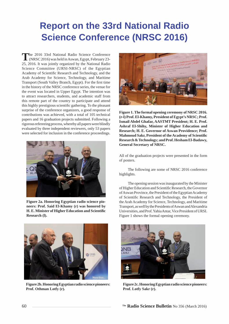
60 The Radio Science Bulletin No 356 (March 2016)
Report on the 33rd National Radio Science Conference (NRSC 2016)
The 2016 33rd National Radio Science Conference (NRSC 2016) was held in Aswan, Egypt, February 23-
25, 2016. It was jointly organized by the National Radio Science Committee (URSI-NRSC) of the Egyptian Academy of Scientifi c Research and Technology, and the Arab Academy for Science, Technology, and Maritime Transport (South Valley Branch, Egypt). For the fi rst time in the history of the NRSC conference series, the venue for the event was located in Upper Egypt. The intention was to attract researchers, students, and academic staff from this remote part of the country to participate and attend this highly prestigious scientifi c gathering. To the pleasant surprise of the conference organizers, a good response of contributions was achieved, with a total of 105 technical papers and 16 graduation projects submitted. Following a rigorous refereeing process, whereby all papers were blindly evaluated by three independent reviewers, only 53 papers were selected for inclusion in the conference proceedings.
All of the graduation projects were presented in the form of posters.
The following are some of NRSC 2016 conference highlights.
The opening session was inaugurated by the Minister of Higher Education and Scientifi c Research, the Governor of Aswan Province, the President of the Egyptian Academy of Scientifi c Research and Technology, the President of the Arab Academy for Science, Technology, and Maritime Transport, as well by the Presidents of Aswan and Alexandria Universities, and Prof. Yahia Antar, Vice President of URSI. Figure 1 shows the formal opening ceremony.
Figure 1. The formal opening ceremony of NRSC 2016. (r-l) Prof. El-Khamy, President of Egypt’s NRSC; Prof. Ismail Abdel Ghafar, AASTMT President; H. E. Prof. Ashraf El-Shihy, Minister of Higher Education and Research; H. E. Governor of Aswan Providence; Prof. Mahmoud Sakr, President of the Academy of Scientifi c Research & Technology; and Prof. Hesham El-Badawy, General Secretary of NRSC.
Figure 2a. Honoring Egyptian radio science pio-neers: Prof. Said El-Khamy (r) was honored by H. E. Minister of Higher Education and Scientifi c Research (l).
Figure 2b. Honoring Egyptian radio science pioneers: Prof. Othman Lotfy (r).
Figure 2c. Honoring Egyptian radio science pioneers: Prof. Lotfy Sakr (r).

The Radio Science Bulletin No 356 (March 2016) 61
Following the tradition of the NRSC conference series, three pioneers of radio science in Egypt were honored, and their contributions to radio theory and practice were acknowledged. They were Prof. Dr. Said El-Khamy (Alexandria University), Prof. Dr. Osman Lotfy (Cairo University), and Eng. Lotfy Sakr (NileSat).
Figures 2a-2c show the honoring of the radio science pioneers.
Following the tradition of the NRSC conference series, three invited talks by distinguished speakers were presented. These were as follows (Figures 3a-3c):
Prof. Dr. Yahia Antar (Royal Military College of Canada and URSI Vice President), “Reactive Energy and the Near-Field in General Antenna Systems”
Prof. Dr. Abdel-Razik Sebak (Concordia University, Canada), “High-Gain Millimeter-Wave Antennas for 5G Wireless and Security Imaging System”
Figure 3a. Invited keynote speaker Prof. Yahia Antar.
Figure 3b. Invited keynote speaker Prof. Abdel-Razik Sebak.
Figure 3c. Invited keynote speaker Prof. Diaa Khalil.
Figure 4a. (r-l) Prof. Mahmoud El-Hadidy, Chair of the Awards Committee; Prof. El-Sayed M. Saad, Vice President of the NRSC; Prof. Said El-Khamy; First best paper awardee Eng. Mai B. S. A. Kafafy from Cairo University; Prof. M. Beshair Saleh, Chair of AASTMT Aswan Branch; and Prof. Hesham El-Badawy, General Secretary of the NRSC.
Figure 4b. Second best paper awardee Eng. George A. Adib from Ain-Shams University is shown third from the left; the others are the same as in Figure 4a.
Figure 4c. Second best student paper awardee Eng. Ahmad S. Mahmoud from MTC is shown second from left; the others are the same as in Figure 4a.

62 The Radio Science Bulletin No 356 (March 2016)
Prof. Dr. Diaa Khalil (Ain Shams University, Egypt), “The MEMS FTIR Spectrometer: An Optical IC to Analyze Everywhere”
Five papers received awards. There were two best paper awards, and three best student paper awards. As usual, URSI contributed 500 Euros towards the best student paper awards. Figures 4a-d show some of the awardees. The winning papers were as follows:
Best Paper Awards
“Stochastic Geometry-Based Analysis of Autonomous Up-link Inter-Cell Interference Coordination in OFDMA/LTE Wireless Systems,” Mai B. S. A. Kafafy and Khaled M. F. Elsayed, Department of Electronics and Communications Engineering, Cairo University, Giza, Egypt.
“Beating Signal Power Level Improvement in Ring Lasers Based on Coupled Ring Resonators,” George A. Adib, Ahmed Shebl, Yasser M. Sabry, and Diaa Khalil, Faculty of Engineering, Ain Shams University, Cairo, Egypt.
Best Student Paper Awards
“A Novel Nonlinearity Measure for RF Amplifi ers in Jamming Applications,” Ahmad S. Mahmoud and Hesham N. Ahmed, Military Technical College, Cairo, Egypt.
“Performance Analysis of LFM Pulse Compression Radar Under Effect of Convolution Noise Jamming,” A Abouelfadl, Mohamed Samir A, Fathy M. Ahmed, Military Technical College, Cairo, Egypt, and Alauddeen H. Asseesy, Arab Academy for Science and Technology and Maritime Transport, Aswan, Egypt.
“An Effi cient Recovery Algorithms Using Complex to Real Transformation of Compressed Sensing,” Wafaa A. Shalaby, Waleed Saad, Mona Shokair, and Moawad I. Dessouky, Faculty of Electronic Engineering, Menoufi a University, Menouf, Egypt.
For the fi rst time at the NRSC conferences, student graduation projects were evaluated, and 10 of them received recognition awards. Figures 5a-5c show some of the winning student teams.
For the fi rst time in the NRSC conference series, the submitted papers were subjected to the IEEE similarity checker. All accepted papers successfully passed the test. The conference papers are now in the process of being submitted to IEEE Xplore.
Also for the fi rst time in the NRSC conference series, all accepted papers were presented, and no absenteeism was recorded. All of the papers receiving awards were coauthored and presented by students.
Figure 4d. Third best student paper awardee Eng. Wafaa A. Shalaby from Menufi a University is shown third from left; the others are the same as in Figure 4a.
Figure 5a. Three best student poster teams from Alexandria University and AASTMT (Alex.).
Figure 5b. (front) The best poster team from AAS-TMT (Alex.). On the right of the stage is Prof. M. Imbaby, Chair of the poster awards committees, announcing the results.
Figure 5c. (front) A winning poster team from Helwan University.

The Radio Science Bulletin No 356 (March 2016) 63
Finally, NRSC 2016 embraced some new activities that were not typical in previous years. These included the following special sessions (the speakers are shown in Figures 6a-6d):
“Cognitive Radio Cloud (CRC): Enabling a Collaborative Environment for Wireless Communication and Network-ing Research”by Prof. Dr. Mustafa El-Nainay and a research team from Alexandria University.
Figure 6a. Special session speaker Prof. Mustafa El-Nainay.
Figure 6b. Special session speaker Prof. Yasser Dessouky.
Figure 6c. Special session speaker Prof. Mahmoud Abdel-Aty.
Figure 6d. Special session speaker Eng. Ahmed Gouda.
“How to Write a Successful Proposal for a Research Project”by Prof. Dr. Yasser Dessouky from AASTMT, Alexandria Branch.
“Scientifi c Publications and Citation Secrets”by Prof. Dr. Mahmoud Abdel-Aty from Sohag University.
“Patent and Prior Arts”by Eng. Ahmad Goudah from AASTMT, Alexandria Branch.
Prof. Mahmoud El-Hadidi, Member of Egypt’s NRSCProf. Said El-Khamy, President of Egypt’s NRSC
E-mail: [email protected]
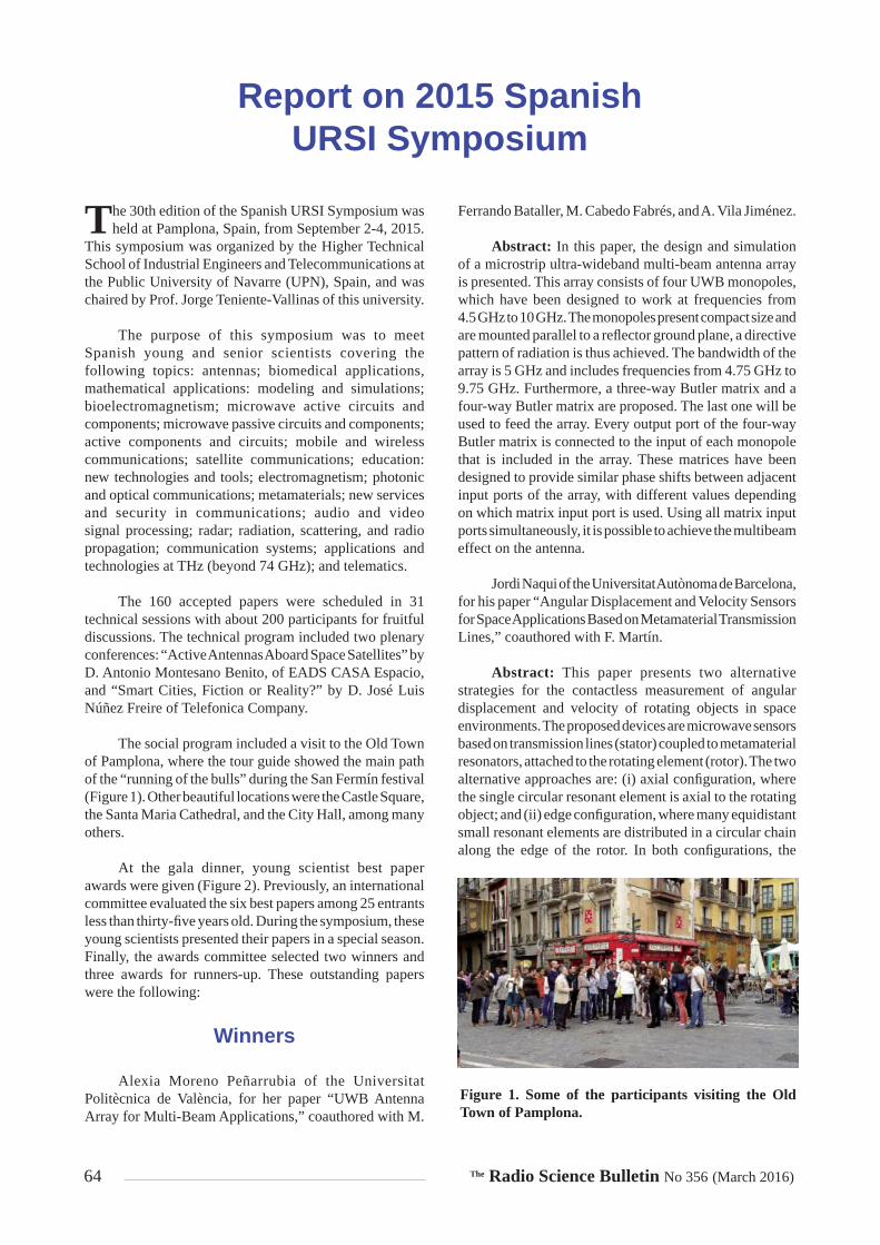
64 The Radio Science Bulletin No 356 (March 2016)
Report on 2015 SpanishURSI Symposium
The 30th edition of the Spanish URSI Symposium was held at Pamplona, Spain, from September 2-4, 2015.
This symposium was organized by the Higher Technical School of Industrial Engineers and Telecommunications at the Public University of Navarre (UPN), Spain, and was chaired by Prof. Jorge Teniente-Vallinas of this university.
The purpose of this symposium was to meet Spanish young and senior scientists covering the following topics: antennas; biomedical applications, mathematical applications: modeling and simulations; bioelectromagnetism; microwave active circuits and components; microwave passive circuits and components; active components and circuits; mobile and wireless communications; satellite communications; education: new technologies and tools; electromagnetism; photonic and optical communications; metamaterials; new services and security in communications; audio and video signal processing; radar; radiation, scattering, and radio propagation; communication systems; applications and technologies at THz (beyond 74 GHz); and telematics.
The 160 accepted papers were scheduled in 31 technical sessions with about 200 participants for fruitful discussions. The technical program included two plenary conferences: “Active Antennas Aboard Space Satellites” by D. Antonio Montesano Benito, of EADS CASA Espacio, and “Smart Cities, Fiction or Reality?” by D. José Luis Núñez Freire of Telefonica Company.
The social program included a visit to the Old Town of Pamplona, where the tour guide showed the main path of the “running of the bulls” during the San Fermín festival (Figure 1). Other beautiful locations were the Castle Square, the Santa Maria Cathedral, and the City Hall, among many others.
At the gala dinner, young scientist best paper awards were given (Figure 2). Previously, an international committee evaluated the six best papers among 25 entrants less than thirty-fi ve years old. During the symposium, these young scientists presented their papers in a special season. Finally, the awards committee selected two winners and three awards for runners-up. These outstanding papers were the following:
Winners
Alexia Moreno Peñarrubia of the Universitat Politècnica de València, for her paper “UWB Antenna Array for Multi-Beam Applications,” coauthored with M.
Ferrando Bataller, M. Cabedo Fabrés, and A. Vila Jiménez.
Abstract: In this paper, the design and simulation of a microstrip ultra-wideband multi-beam antenna array is presented. This array consists of four UWB monopoles, which have been designed to work at frequencies from 4.5 GHz to 10 GHz. The monopoles present compact size and are mounted parallel to a refl ector ground plane, a directive pattern of radiation is thus achieved. The bandwidth of the array is 5 GHz and includes frequencies from 4.75 GHz to 9.75 GHz. Furthermore, a three-way Butler matrix and a four-way Butler matrix are proposed. The last one will be used to feed the array. Every output port of the four-way Butler matrix is connected to the input of each monopole that is included in the array. These matrices have been designed to provide similar phase shifts between adjacent input ports of the array, with different values depending on which matrix input port is used. Using all matrix input ports simultaneously, it is possible to achieve the multibeam effect on the antenna.
Jordi Naqui of the Universitat Autònoma de Barcelona, for his paper “Angular Displacement and Velocity Sensors for Space Applications Based on Metamaterial Transmission Lines,” coauthored with F. Martín.
Abstract: This paper presents two alternative strategies for the contactless measurement of angular displacement and velocity of rotating objects in space environments. The proposed devices are microwave sensors based on transmission lines (stator) coupled to metamaterial resonators, attached to the rotating element (rotor). The two alternative approaches are: (i) axial confi guration, where the single circular resonant element is axial to the rotating object; and (ii) edge confi guration, where many equidistant small resonant elements are distributed in a circular chain along the edge of the rotor. In both confi gurations, the
Figure 1. Some of the participants visiting the Old Town of Pamplona.

The Radio Science Bulletin No 356 (March 2016) 65
sensing principle is based on the symmetry-related control of the coupling between the line and the resonant elements. With the reported approaches, practically unlimited rotation speeds can be measured with high accuracy. The proposed sensors can be applied for the attitude control of space vehicles by the precise measurement of the rotation angle and velocity of reaction wheels.
Awards for Runners-Up
Juan Córcoles of the University Autónoma de Madrid, for his paper “Methodology to Reduce Radiofrequency Heating of an Elongated Medical Implant in a Patient Undergoing a Magnetic Resonance Image Examination,” coauthored with E. Zastrow.
Abstract: This work presents a methodology to design the radiofrequency (RF) excitations in a magnetic resonance imaging (MRI) scanner to reduce RF-induced heating at hotspots in the surrounding tissues of tips of elongated active implantable medical devices (AIMDs). With the proposed method, the specifi c absorption rate at these hotspots is explicitly constrained while maximizing homogeneity of the RF magnetic fi eld to enhance imaging quality in the region of interest. The formulation can incorporate a Tier 4 or Tier 3 (highest tiers)-compliant AIMD model from the current ISO technical specifi cation regarding this safety issue (ISO/TS 10974:2012). The resulting problem can be solved via convex programming. The methodology (design and simulation setup, formulation and optimization, implant modeling) is comprehensively described in the text. The implementation of the proposed method is demonstrated through an example consisting of a simple AIMD emulating a spinal-cord stimulator placed inside a numerical human model in a typical 1.5 T MRI RF body coil. Results for this confi guration are presented to show the effectiveness of the proposed method.
Carlos Gordón of the University Carlos III de Madrid for his paper, “E-Band Wireless Link Using an On-Chip Colliding Pulse Passive Mode-Locked Laser Diode
Structure,” coauthored with R. Guzmán, V. Corral, X. Leijtens, and G. Carpintero.
Abstract: Broadband wireless communications are enabled by the wide bandwidths available for carrying information in the millimeter-wave range (30 GHz to 300 GHz). Photonic technologies can be used to develop compact transmitters operating at millimeter-wave carrier frequencies, recently demonstrating the use of photonic integration to address size, cost, reliability, and performance. In this paper, we present a pulsed source designed for signal generation. The key component is an on-chip colliding-pulse passive mode-locked laser diode (OCCP-MLLD) structure operating at 70 GHz. We demonstrate a 1 Gbps and 2 Gbps data rate wireless link that does not require any stabilization scheme due to the OCCP-MLLD structure, and does not require high-frequency electronics for its operation. A novel building-block multimode interference refl ector is used to integrate on-chip a colliding-pulse passive mode-locked laser diode structure, without the need for cleaved facets to defi ne the laser cavity.
Pablo Padilla of the University of Granada for his paper, “Planar Multilayered Printed Refl ectarrays for Satellite Communications in Ku-Band,” coauthored with T. Muñoz Rodero, J. Manuel Fernández, J. L. Padilla, and J. F. Valenzuela Valdés.
Abstract: This document contains a complete description of the design and development of different reflectarray designs. These radiating devices are conceived for their use in satellite communications at microwave frequencies. The designs are conceived to provide a wide band in terms of bandwidth. Both circular polarization and linear polarization confi gurations are considered and provided. The working principle of the refl ectarray is based on the reception and front-wave correction by means of printed phase shifters embedded in a phased-array structure. The work is organized in two stages. The fi rst one is focused on the selection and design of the unitary radiating element of the array. The second one is based on the complete refl ectarray defi nition and building up with one of the designed unitary elements (the most suitable one). Design specifi cations and constraints, manufactured prototypes, and their performance results are provided in this work.
The next edition of the Spanish URSI Symposium will be held in Madrid, Spain, September 6-8, 2016. It will be organized by the University Autonoma de Madrid (UAM), Spain.
F. J. Ares-Pena and J. A. Rodríguez-González Spanish URSI Member Committee
University of Santiago de Compostela, SpainE-mails: [email protected]; [email protected]
Figure 2. Alexia Moreno Peñarrubia and Jordi Naqui (on the left) receiving the Young Scientist Best Paper Awards, together with the fi nalists.

66 The Radio Science Bulletin No 356 (March 2016)
URSI Conference CalendarMay 2016
Workshop on Frequencies and Radio Sciences 2016Paris, France, 3 May 2016Contact: Ms. Valérie Alidor, Tel : +33 1 56 90 37 02, E-mail : [email protected]://www.frequencesetradiosciences2016.fr/
CROWNCOM 201611th International Conference on Cognitive Radio Oriented Wireless Networks and CommunicationsGrenoble, France, 30 May - 1 June 2016Contact: Prof. Jacques Palicot, SUPELEC/IETR, Avenue de la Boulaie, CS 47601 F35576 Cesson-Sévigné, France, E-mail: [email protected]://crowncom.org/2016
June 2016
EUSAR 2016 - European Conference on Synthetic Aperture Radar 2016Hamburg, Germany, 6-9 June 2016 Contact: EUSAR 2016 Conference Offi ce c/o VDE, Ms. Hatice Altintas, Stresemannallee 15, D-60596 Frankfurt, GermanyFax: +49 69 96 31 52 13, E-Mail: [email protected]://www.eusar.de
MSMW 2016 and TeraTech 20169th International Kharkiv Symposium on Physics and Engineering of Microwaves, Millimeter and SubMillimeter Waves and Workshop on Terahertz TechnologiesKharkiv, Ukraine, 20-24 June 2016Contact: Scientifi c and Technical Information, O.Ya. Usikov Institute for Radiophysics and Electronics NASU, ul. Acad. Proskury 12, Kharkiv, 61085, Ukraine, Fax: +380-57-315-2105http://www.msmw.org.ua
MetroAeroSpace 20163rd IEEE International Workshop on Metrology for AerospaceFirenze, Italy, 22-23 June 2016Contact: Contact: L. Ciani, Univ. of Florence, Dept of Information Engineering, via di S. Marta 3, 50139 Florence, Italy, E-mail: lorenzo.ciani@unifi .it and L. De Vito, Univ. of Sannio, Dept of Engineering, 82100 Benevento, Italy, E-mail: [email protected] http://lesim1.ing.unisannio.it
BSS 2016Beacon Satellite Symposium 2016Trieste, Italy, 27 June - 1 July 2016
Contact: Ms. Patricia Doherty, Chair, Beacon Satellite Studies Working Group, E-mail [email protected]://t-ict4d.ictp.it/beacon2016/
July 2016
MMET 201616th International Conference on Mathematical Methods in Electromagnetic TheoryLviv, Ukraine, 5-7 July 2016Contact: Dr. Alexander Nosich, MMET 2016 TPC Co-Chairman, Laboratory of Micro and Nana Optics, IRE NASU, vul. Proskury 12, Kharkiv 61085, Ukraine, Fax (380-57) 315-2105, E-mail [email protected]://www.mmet.org/2016
ISPRS-URSI sessionSpS15 - URSI-ISPRS Joint Special Session: “Disaster and Risk Management”Prague, Czech Republic, 12-19 July 2016Contact: Prof. Tullio Joseph Tanzi (URSI) E-mail: [email protected] and Prof Orhan Altan(ISPRS 1st Vice President) E-mail:[email protected]://www.isprs2016-prague.com/
COSPAR 201641st Scientifi c Assembly of the Committee on Space Research (COSPAR) and Associated EventsIstanbul, Turkey, 30 July – 7 August 2016Contact: COSPAR Secretariat, 2 place Maurice Quentin, 75039 Paris Cedex 01, France, Tel: +33 1 44 76 75 10, Fax: +33 1 44 76 74 37, E-mail: [email protected]://www.cospar-assembly.org/
August 2016
EMTS 20162016 URSI Commission B International Symposium on Electromagnetic TheoryEspoo, Finland, 14-18 August 2016Contact: Prof. Ari Sihvola, Aalto University, School of Electrical Engineering, Department of Radio Science and Engineering, Box 13000, FI-00076 AALTO, Finland, E-mail: [email protected]
HF13Nordic HF Conference with Longwave Symposium LW 13Faro, Sweden (north of Gotland in the Baltic Sea), 15-17 August 2016Contact: Carl-Henrik Walde, Tornvägen 7, SE-183 52 Taby, Sweden, tel +46 8 7566160 (manual fax switch, E-mail [email protected]://www.ursi.org/img/website24x24.jpg

The Radio Science Bulletin No 356 (March 2016) 67
AP-RASC 20162016 URSI Asia-Pacifi c Radio Science ConferenceSeoul, Korea, 21 - 25 August 2016Contact: URSI AP-RASC 2016 Secretariat, Genicom Co Ltd, 2F 927 Tamnip-dong, Yuseong-gu, Daejeon, Korea 305-510, Fax.: +82-42-472-7459, E-mail: [email protected]://www.ursi.org/img/website24x24.jpg
September 2016
International Symposium on Turbo Codes and Iterative Information ProcessingBrest, France, 5-9 September 2016Contact: If for submission issues, please contact [email protected]://conferences.telecom-bretagne.eu/turbocodes
Next-GWiN Workshop 20164th International Workshop on Next Generation Green Wireless NetworksDublin, Ireland, 12-13 September 2016Contact: Prof. Jacques Palicot, Supelec, Rennes, France, E-mail: [email protected]://www.next-gwin.org/
ICEAA 2016Eighteenth edition of the International Conference on Electromagnetics in Advanced ApplicationsCairns, Australia, 19-23 September 2016Contact: Prof. Guido Lombardi, Politecnico di Torino, E-mail: [email protected]://www.iceaa-offshore.org/j3/
Metamaterials 201610th International Congress on Advanced Electromagnetic Materials in Microwaves and OpticsChania, Greece, 19-22 September 2016Contact: http://congress2016.metamorphose-vi.org/http://congress2016.metamorphose-vi.org
VERSIM 2016VLF/ELF Remote Sensing of Ionospheres and Magnetospheres WorkgroupHermanus, Western Cape, South Africa, 19-23 September 2016Contact: [email protected]://events.sansa.org.za/versim-information
October 2016
RFI 2016Radio Frequency Interference 2016Socorro, NM, USA, 10-13 October 2016Contact: Prof. Willem Baan, Asserweg 45, NL-9411 LP Beilen, The Netherlands, E-mail: [email protected](website in preparation)
RADIO 2016IEEE Radio and Antenna Days of the Indian Ocean 2016Réunion Island, 10-13 October 2016Contact: [email protected]://www.radiosociety.org/radio2016/
ISAP 20162016 International Symposium on Antennas and PropagationOkinawa, Japan, 24-28 October 2016Contact: Prof. Toru Uno, Tokyo Univ. of Agriculture & Technology, Dept of Electrical and Electronic Engineering, 2-24-16 Nakamachi, Koganei 184-8588, Japan, Fax +81 42-388 7146, E-mail: [email protected]://isap2016.org/
November 2016
SCOSTEP/ISWI International School on Space ScienceSangli, India, 7-17 November 2016Contact: Dr. Dadaso Jaypal Shetti, Department of Physics, Smt. Kasturbai Walchand College, Sangli, Maharashtra-416416, India, E-mail:- [email protected], Fax: +91-233-2327128http://www.iiap.res.in/meet/school_meet/index.php
August 2017
URSI GASS 2017XXXIInd URSI General Assembly and Scientific SymposiumMontreal, Canada, 19-26 August 2017Contact: URSI Secretariat, Ghent University - INTEC, Technologiepark - Zwijnaarde 15, 9052 Gent, Belgium, E-mail [email protected]
May 2018
AT-RASC 2018Second URSI Atlantic Radio Science ConferenceGran Canaria, Spain, 28 May – 1 June 2018Contact: Prof. Peter Van Daele, URSI Secretariat, Ghent University – INTEC, Technologiepark-Zwijnaarde 15, B-9052 Gent, Belgium, Fax: +32 9-264 4288, E-mail address: E-mail: [email protected]://www.at-rasc.com
May 2019
EMTS 20192019 URSI Commission B International Symposium on Electromagnetic TheorySan Diego, CA, USA, 27-31 May 2019Contact: Prof. Sembiam R. Rengarajan, California State University, Northridge, CA, USA, Fax +1 818 677 7062, E-mail: [email protected]
68 The Radio Science Bulletin No 356 (March 2016)
Information for Authors
Content
The Radio Science Bulletin is published four times per year by the Radio Science Press on behalf of URSI, the International Union of Radio Science. The content of the Bulletin falls into three categories: peer-reviewed scientifi c papers, correspondence items (short technical notes, letters to the editor, reports on meetings, and reviews), and general and administrative information issued by the URSI Secretariat. Scientifi c papers may be invited (such as papers in the Reviews of Radio Science series, from the Commissions of URSI) or contributed. Papers may include original contributions, but should preferably also be of a suffi ciently tutorial or review nature to be of interest to a wide range of radio scientists. The Radio Science Bulletin is indexed and abstracted by INSPEC.
Scientific papers are subjected to peer review. The content should be original and should not duplicate information or material that has been previously published (if use is made of previously published material, this must be identifi ed to the Editor at the time of submission). Submission of a manuscript constitutes an implicit statement by the author(s) that it has not been submitted, accepted for publication, published, or copyrighted elsewhere, unless stated differently by the author(s) at time of submission. Accepted material will not be returned unless requested by the author(s) at time of submission.
Submissions
Material submitted for publication in the scientifi c section of the Bulletin should be addressed to the Editor, whereas administrative material is handled directly with the Secretariat. Submission in electronic format according to the instructions below is preferred. There are typically no page charges for contributions following the guidelines. No free reprints are provided.
Style and Format
There are no set limits on the length of papers, but they typically range from three to 15 published pages including fi gures. The offi cial languages of URSI are French and English: contributions in either language are acceptable. No specifi c style for the manuscript is required as the fi nal layout of the material is done by the URSI Secretariat. Manuscripts should generally be prepared in one column for printing on one side of the paper, with as little use of automatic formatting features of word processors as possible. A complete style guide for the Reviews of Radio Science can be downloaded from http://www.ips.gov.au/IPSHosted/NCRS/reviews/. The style instructions in this can be followed for all other Bulletin contributions, as well. The name, affi liation, address, telephone and fax numbers, and e-mail address for all authors must be included with
All papers accepted for publication are subject to editing to provide uniformity of style and clarity of language. The publication schedule does not usually permit providing galleys to the author.
Figure captions should be on a separate page in proper style; see the above guide or any issue for examples. All lettering on fi gures must be of suffi cient size to be at least 9 pt in size after reduction to column width. Each illustration should be identifi ed on the back or at the bottom of the sheet with the fi gure number and name of author(s). If possible, the fi gures should also be provided in electronic format. TIF is preferred, although other formats are possible as well: please contact the Editor. Electronic versions of fi gures must be of suffi cient resolution to permit good quality in print. As a rough guideline, when sized to column width, line art should have a minimum resolution of 300 dpi; color photographs should have a minimum resolution of 150 dpi with a color depth of 24 bits. 72 dpi images intended for the Web are generally not acceptable. Contact the Editor for further information.
Electronic Submission
A version of Microsoft Word is the preferred format for submissions. Submissions in versions of TEX can be accepted in some circumstances: please contact the Editor before submitting. A paper copy of all electronic submissions must be mailed to the Editor, including originals of all fi gures. Please do not include fi gures in the same fi le as the text of a contribution. Electronic fi les can be send to the Editor in three ways: (1) By sending a fl oppy diskette or CD-R; (2) By attachment to an e-mail message to the Editor (the maximum size for attachments after MIME encoding is about 7 MB); (3) By e-mailing the Editor instructions for downloading the material from an ftp site.
Review Process
The review process usually requires about three months. Authors may be asked to modify the manuscript if it is not accepted in its original form. The elapsed time between receipt of a manuscript and publication is usually less than twelve months.
Copyright
Submission of a contribution to the Radio Science Bulletin will be interpreted as assignment and release of copyright and any and all other rights to the Radio Science Press, acting as agent and trustee for URSI. Submission for publication implicitly indicates the author(s) agreement with such assignment, and certifi cation that publication will not violate any other copyrights or other rights associated with the submitted material.

The Radio Science Bulletin No 356 (March 2016) 69
Application for an URSI Radioscientist
APPLICATION FOR URSI RADIOSCIENTIST
I have not attended the last URSI General Assembly & Scientifi c Symposium, and wish to remain/become an URSI Radioscientist in the 2014-2017 triennium. This application includes a subscription to The Radio Science Bulletin and inclusion in the URSI mailing lists.
(Please type or print in BLOCK LETTERS)
Name : Prof./Dr./Mr./Mrs./Ms. ____________________________________________________________________ Family Name First Name Middle Initials
Present job title: _______________________________________________________________________________
Years of professional experience: ___________________
Professional affi liation: __________________________________________________________________________
I request that all information be sent to my home business address, i.e.:
Company name: _______________________________________________________________________________
Department: ___________________________________________________________________________________
Street address: _________________________________________________________________________________
City and postal/zip code: _________________________________________________________________________
Province/State: ________________________________________ Country: ________________________________
Tel: ext. _________ Fax: _______________________________________
E-mail: _______________________________________________________________________________________
Areas of interest (Please tick)
AElectromagnetic Metrology
FWave Propagation & Remote Sensing
BFields and Waves
GIonospheric Radio and Propagation
CRadio-Communication Systems & Signal Processing
HWaves in Plasmas
DElectronics and Photonics
JRadio Astronomy
EElectromagnetic Environment & Interference
KElectromagnetics in Biology & Medicine
By signing up, you agree to be included into the URSI mailing list. You can unsubscribe at any time.
I agree that my contact details will be used by URSI only and will never be transferred to other parties.
Please return this signed form to :
The URSI SecretariatGhent University - INTEC
Technologiepark - Zwijnaarde B-9052 GHENT, BELGIUM
E-mail: [email protected]
Related Documents