Radio Frequency Fundamentals (Source: CWNA/CWSP Exam guide: Tom Carpenter)

Radio Frequency Fundamentals_1.pptx
Dec 15, 2015
Welcome message from author
This document is posted to help you gain knowledge. Please leave a comment to let me know what you think about it! Share it to your friends and learn new things together.
Transcript

Radio Frequency Fundamentals
(Source: CWNA/CWSP Exam guide: Tom Carpenter)

An electromagnetic wave is a fluctuation or variation of energy consisting of electric and magnetic fields.
The electric and magnetic fields oscillate or move back and forth at right angles to each other, and the wave moves out from the propagating antenna in a direction related to the shape of the antenna.
RF Introduction


The most important RF characteristics are 1. Wavelength2. Frequency3. Amplitude4. Phase
RF Characterstics

The wavelength of an RF wave is calculated as the distance between two adjacent identical points on the wave.
Wavelength

Wavelength dictates the optimum size of the receiving antenna and determines how the RF wave will interact with its environment.
For example, an RF wave will react differently when it strikes an object that is large in comparison to the wavelength than when it strikes an object that is small in comparison to the wavelength.
Why wavelength important?

Frequency refers to the number of wave cycles that occur in a given window of time (usually in one second).
Frequency and wavelength are related through the following formula:
λ=c/f; where λ is the wavelength, c is the speed of
light in vacuum, which is 3x10⁸m/sec and f is the frequency.
Frequency
Amplitude is a measurement of the signal’s strength or power.
Amplitude modulation schemes represent data through changes in the signal’s strength.
Amplitude


Amplitude An RF wave with greater amplitude is easier
to detect than an RF wave with lesser amplitude, assuming all other factors are equal.
A wave with a lesser amplitude may not be detectable due to the noise floor.
The noise floor can be defined as a measure of the level of background noise.

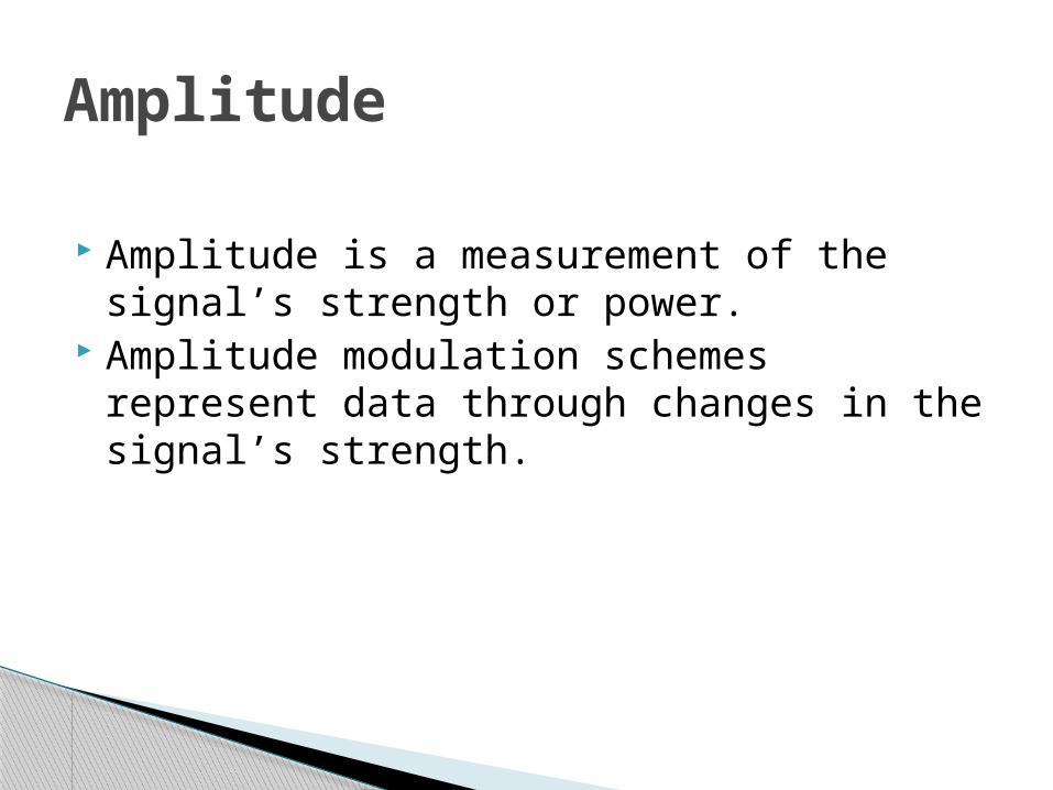
Unlike wavelength, frequency, and amplitude, phase is not a characteristic of a single RF wave but is instead a comparison between two RF waves.
If two copies of the same RF wave arrive at a receiving antenna at the same time, their phase state will impact how the composite wave is able to be used.
When the waves are in phase, they strengthen each other; when the waves are out of phase, they sometimes strengthen and sometimes cancel each other ( In specific out-of-phase cases, they only cancel each other).
Phase
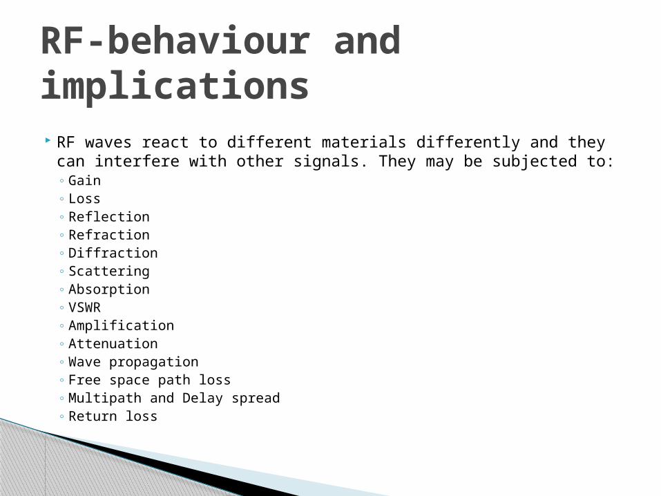
RF-behaviour and implications RF waves react to different materials differently and they can
interfere with other signals. They may be subjected to:◦ Gain◦ Loss◦ Reflection◦ Refraction◦ Diffraction◦ Scattering◦ Absorption◦ VSWR◦ Amplification ◦ Attenuation◦ Wave propagation◦ Free space path loss◦ Multipath and Delay spread◦ Return loss

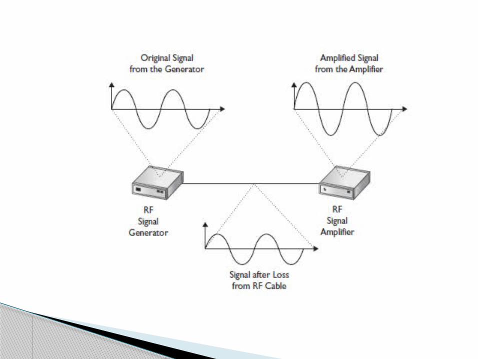
Gain is defined as the positive amplitude difference between two RF wave signals
Amplification is an active process used to increase an RF signal’s amplitude and, therefore, results in gain.
Two basic types of gain exist: ◦ active and ◦ passive.
Gain

Active gain is achieved by placing an amplifier in-line between the RF signal generator (such as an access point) and the propagating antenna.
These amplifiers usually specify the gain they provide in decibels (dB).
Active Gain

Passive Gain Passive gain is not an actual increase in the
amplitude of the signal delivered to the intentional radiator, but it is an increase in the amplitude of the signal, in a favoured direction, by focusing or directing the output power.
Unintentional passive gain happens because of reflection and scattering in a coverage area.

Loss is defined as the negative amplitude difference between two RF signals.
Like gain, loss can be either intentional or unintentional.
Intentional Loss may be due to FCC regulation (or other regulatory reasons)
Natural kind of loss (unintentional) happens because of the normal process of RF propagation, which involves spreading, reflection, refraction, scattering, diffraction, and absorption.
Loss

When an RF signal bounces off of a smooth, nonabsorptive surface, changing the direction of the signal, it is said to reflect and the process is known as reflection
RF signals reflect off objects that are smooth and larger than the waves (wave length) that carry the signals.
Reflection
Wavelengths are between 5 to 13Cms. Objects will be greater than 5 centimetres in
size (for 5 GHz U-NII bands) or 13 centimetres in size (for the 2.4 GHz ISM band) and smooth reflect these waves.
Some RF energy is absorbed during reflection
Reflection: 802.11 specific

Refraction occurs when an RF signal changes speed and is bent while moving through media of different densities.
Different mediums, such as drywall, wood, or plastic, will have different refraction indexes. The refraction index helps in determining how much refraction will occur.
Refraction

Common causes of refraction include changes in temperature, changes in air pressure, or the existence of water vapour.
if the RF signal changes from the intended direction as it’s travelling from the transmitter to the receiver, the receiver may not be able to detect and process the signal. The result can be a broken connection or an increase in error rates if the refraction is temporary or sporadic due to fluctuations in the weather around the area of the link.


Diffraction is defined as a change in the direction and/or intensity of a wave as it passes by the edge of an obstacle
The RF shadow caused by diffraction can result in areas without proper RF coverage.
Diffraction


Scattering Scattering happens when an RF signal
strikes an uneven surface (a surface with inhomogeneities) causing the signal to be scattered instead of absorbed so that the resulting signals are less significant than the original signal.
Another way to define scattering is to say that it is multiple reflections.


Absorption Absorption is the conversion of the RF signal
energy into heat. This conversion happens because the
molecules in the medium through which the RF signal is passing cannot move fast enough to “keep up” with the RF waves.
Many materials absorb RF signals in the 2.4 GHz ISM spectrum. These include water, drywall, wood, and even humans
Though Microwave ovens also use 2.4Ghz spectrum, they use an output power between 700-1400Watts, where as WLAN use between 30 milliwatts and 4 watts.
Ovens use absorption to convert RF signals into heat.
Microwave ovens


Voltage Standing Wave Ratio (VSWR)
measurement of mismatched impedance in an RF system and is stated as an X:1 (read as “X to one”) ratio.
Before the RF signal is radiated through space by the antenna, it exists as an alternating current (AC) within the transmission system. Within this hardware, RF signal degradation occurs. All cables, connectors, and devices have some level of inherent loss. In a properly designed system, this loss by attenuation is unavoidable. However, the situation can be even worse if all the cables and connectors do not share the same impedance level.


Return Loss
When there is VSWR greater than 1.0:1, there is some level of power loss due to backward reflection of the RF signal within the system.
This energy that is reflected back toward the RF generator or transmitter results in return loss.
Return loss is a measurement, usually expressed in decibels, of the ratio between the forward current (incident wave) and the reflected current (reflected wave).
To avoid grater Return Loss, we have to avoid impedance mismatch.

Amplification is an increase of the amplitude of an RF signal.
Amplification is achieved through active gain and is accomplished with an amplifier.
Amplification

Attenuation is the process of reducing an RF signal’s amplitude.
This is occasionally done intentionally with attenuators to reduce a signal’s strength within a regulatory domain’s imposed constraints.
Attenuation

Free space path loss, sometimes called free space loss (FSL) or just path loss, is a weakening of the RF signal due to a broadening of the wave front.
The broadening of the wave front is known as signal dispersion.
The broadening of the wave is also sometimes called beam divergence.
Beam divergence can be calculated by subtracting the beam diameter (D1) at a greater distance from the beam diameter (D2) closer to the antenna and then dividing by the distance between these two points (L). The following formula illustrates this:
Divergence = (D1 – D2) / L
Free space path loss

When signals bounce around in an environment through reflection, refraction, diffraction, and scattering, they create an effect known as multipath.
Multipath occurs when multiple paths of the signal, understood as multiple signals, arrive at the receiving antenna at the same time or within a small fraction of a second (nanoseconds) of each other.
Multipath can also occur outdoors when signals reflect off of large objects in the RF link path
Multipath and Delay Spread
Related Documents