Radio Frequency Analysis at Fiber- Based Cell Sites with an OBSAI Interface White Paper Radio equipment at conventional cell sites is located at the base of the tower, transmitting RF signals via coax to antennas at the top of the tower. However, these coax-based feeders produce most problems in cell sites due to their inherent loss and susceptibility to interference. In addition, environmental conditions deteriorate cables and connectors, creating signal reflections and intermodulation. Modern cell sites have a distributed architecture where the radio is divided into two main elements. A baseband unit (BBU) performs radio functions on a digital baseband domain that resides at the base of the towers; and, a remote radio head (RRH) performs radio frequency (RF) functions on an analog domain installed next to the antennas at the top of the tower. These two radio elements, the BBU and RRH, communicate via a standard interface such as the common public radio interface (CPRI) or Open Base Station Architecture Initiative (OBSAI). Industry Standards CPRI is an industry standard aimed at defining a publicly available specification for the internal interface of wireless base stations between the BBU and RRH. The parties cooperating to define the specification are Ericsson, Huawei, NEC, Alcatel Lucent, and Nokia Siemens Networks. A similar interface specification was developed by OBSAI that defines a set of specifications providing the architecture, function descriptions, and minimum requirements for integrating common modules into a base transceiver station (BTS). More specifically, reference point 3 (RP3) interchanges user and signaling data between the BBU and the RRH. The main network-element manufacturer members of OBSAI include ZTE, NEC, Nokia Siemens Networks, Samsung, and Alcatel Lucent. In addition to CPRI and OBSAI, the European Telecommunications Standards Institute (ETSI) has defined the open radio equipment interface (ORI) to eliminate proprietary implementations and achieve interoperability between multi-vendor BBUs and RRHs. ORI specifications are based on CPRI and expand on the specifications of the interface.

Welcome message from author
This document is posted to help you gain knowledge. Please leave a comment to let me know what you think about it! Share it to your friends and learn new things together.
Transcript

Radio Frequency Analysis at Fiber-Based Cell Sites with an OBSAI Interface
White Paper
Radio equipment at conventional cell sites is located at the base of the tower, transmitting RF signals via coax to antennas at the top of the tower. However, these coax-based feeders produce most problems in cell sites due to their inherent loss and susceptibility to interference. In addition, environmental conditions deteriorate cables and connectors, creating signal reflections and intermodulation.
Modern cell sites have a distributed architecture where the radio is divided into two main elements. A baseband unit (BBU) performs radio functions on a digital baseband domain that resides at the base of the towers; and, a remote radio head (RRH) performs radio frequency (RF) functions on an analog domain installed next to the antennas at the top of the tower.
These two radio elements, the BBU and RRH, communicate via a standard interface such as the common public radio interface (CPRI) or Open Base Station Architecture Initiative (OBSAI).
Industry StandardsCPRI is an industry standard aimed at defining a publicly available specification for the internal interface of wireless base stations between the BBU and RRH. The parties cooperating to define the specification are Ericsson, Huawei, NEC, Alcatel Lucent, and Nokia Siemens Networks.
A similar interface specification was developed by OBSAI that defines a set of specifications providing the architecture, function descriptions, and minimum requirements for integrating common modules into a base transceiver station (BTS). More specifically, reference point 3 (RP3) interchanges user and signaling data between the BBU and the RRH. The main network-element manufacturer members of OBSAI include ZTE, NEC, Nokia Siemens Networks, Samsung, and Alcatel Lucent.
In addition to CPRI and OBSAI, the European Telecommunications Standards Institute (ETSI) has defined the open radio equipment interface (ORI) to eliminate proprietary implementations and achieve interoperability between multi-vendor BBUs and RRHs. ORI specifications are based on CPRI and expand on the specifications of the interface.

2 Radio Frequency Analysis at Fiber-Based Cell Sites with an OBSAI Interface
Testing Distributed Cell SitesA distributed cell site architecture provides the benefit of replacing coax-based feeders with fiber-based feeders. This significantly reduces signal loss and reflections. However, since all RF functions reside on the RRH, any RF maintenance or troubleshooting such as interference analysis requires reaching the top of the tower to get access to the RRH. This represents a higher operational expense and security concern.
These new test challenges for distributed cell sites add to existing testing requirements since the radio access network is a mix of conventional and distributed cell sites. An effective test solution must consolidate installation and maintenance tests:
y Cell site installation requires verification tests for coax-based feeders related to signal reflection, including return loss or voltage standing wave ratios (VSWR), distance to fault, and RF transmitted power; and, for fiber-based feeders, optical and fiber metrics including optical transmitted power and fiber inspection tests
y Cell site maintenance, in addition to requiring the same verification tests performed during installation, needs conformance tests related to signal integrity including RF characteristics, interference analysis, and modulation quality to ensure quality of service
Viavi worked closely with mobile service providers to create CellAdvisor™, a comprehensive test solution for installing and maintaining cell sites. It is an integrated solution capable of characterizing both RF and fiber and it tests signal quality to ensure quality of experience for mobile users. It also includes RF over CPRI (RFoCPRI™) and RF over OBSAI (RFoOBSAI™) technologies that de-map RF components from CPRI/OBSAI on the ground, reducing maintenance costs and minimizing security concerns.
OBSAI StandardOBSAI specifications provide the architecture, functional descriptions, and minimum requirements for integrating a set of common modules in a BTS. A BTS comprises of four main blocks or logical entities. A block represents a logical grouping of a set of functions and attributes. A block may consist of one or more modules, each of which represents a physical implementation of a subset of the block functions. One of the key objectives of OBSAI was to create an open market for BTS components by defining standard interfaces to connect these four modules.
Figure 1. OBSAI functional blocks reference architecture
Control and clock block(1-2 modules)
RF module(1-9 modules)
Baseband module(1-12 modules)
Transport module(1-2 modules)
RP3RP2
RP1

3 Radio Frequency Analysis at Fiber-Based Cell Sites with an OBSAI Interface
1. The transport module (TM) interfaces to external network, and provides functions such as quality of service (QoS), security functions, and synchronization.
2. The baseband module (BBM) consists of one or more modules that perform baseband processing for the air interfaces that include but are not limited to GSM, CDMA200, WCDMA, and WiMAX. These functions include encoding/decoding, interleaving, spreading, modulation, multiplexing/demultiplexing, ciphering/deciphering, protocol frame processing, and multiple input multiple output (MIMO) processing.
3. The radio frequency module (RFM) provides the capability for concurrent operation of two or more of the air interfaces for GSM, WCDMA, HSDPA, CDMA, and WiMAX with a variable channel bandwidth as an integer multiple of 1.25, 1.5, and 1.75 MHz with a maximum of 20 MHz. The main functions of this RF block include digital to analog conversion, carrier selection, antenna interface, RF filtering, diversity and, and amplification.
4. The control and clock module (CCM) controls BTS resources, supervises all BTS activities, monitors BTS status and reports BTS status and performance.
OBSAI Architecture The general principles of the architecture and interfaces for open BTS are as follows:
y Define an open, standardized internal modular structure of wireless base stations.
y Define a set of standard BTS modules with specified form, fit, and function such that BTS vendors can acquire and integrate modules from multiple vendors in an OEM fashion.
y Define open, standards-based digital interfaces between BTS modules based on a logical model of the entity controlled through the interfaces.
y Define open, standards-based interfaces to assure interoperability and compatibility between BTS modules.
y Define an open, standardized interface for exchange of clock and synchronization signals that meet the timing, frequency stability, phase noise, and jitter constraints of supported air interfaces.
y Define a set of standard OAM&P principles for integration of multiple modules from multiple vendors into a functioning base station.
y Define the internal modular structure for the base station to allow scalability for small to large capacity configurations.
y Define the internal modular structure for the base station to support concurrent operation with different air interface standards.
The architecture elements consist of the following:
y Functional blocks consisting of the transport block, control and clock block, baseband block and RF block. A block represents a logical grouping of a set of functions and attributes
y External network interface: examples are: (Iub) to the radio network controller (RNC) for 3GPP systems, (Abis) to the base station controller (BSC) for 3GPP2 systems, R6 to ASN GW (centralized GW) or R3 to CSN (distributed GW) for 802.16/WiMAX system
y External radio interface: examples are Uu or Um to the poor and lower case (UE) for 3GPP systems (for example, GSM or WCDMA), Um for 3GPP2 systems (for example, CDMA) or R1 for IEEE802.16/WiMAX
y Internal interfaces between BTS functional blocks designated as reference point 1 (RP1), reference point 2 (RP2), and reference point 3 (RP3). RP1 includes control data and clock signals to all blocks. RP2 provides transport for user data between a transport block and baseband block. RP3 provides transport for air interface data between a baseband block and RF block. RP4 provides the DC power interface between the internal modules and DC power sources.
4 Radio Frequency Analysis at Fiber-Based Cell Sites with an OBSAI Interface
Reference Point 3 ArchitectureAn OBSAI reference point 3 (RP3) interface exists between an RF block and baseband block of a base station. This interface has a maximum of 9 pairs of unidirectional links with differential signaling toward the RP3 interface. Among the implemented links with differential signaling, unused links shall be disabled for power conservation purposes.
There are two main topologies suggested between the BBM and the RFM:
y Mesh: configured with (N) baseband modules and (M) RF modules for a total of (N x M) pairs of unidirectional links with differential signaling; in case of high-speed throughput, it will be possible to configure several parallel pairs of unidirectional links between any baseband and RF modules
Figure 2. OBSAI mesh topology
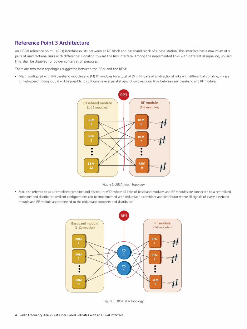
y Star: also referred to as a centralized combiner and distributor (CD) where all links of baseband modules and RF modules are connected to a centralized combiner and distributor; resilient configurations can be implemented with redundant a combiner and distributor where all signals of every baseband module and RF module are connected to the redundant combiner and distributor
Figure 3. OBSAI star topology
RF module(1-9 modules)
Baseband module(1-12 modules)
RP3
RF module(1-9 modules)
Baseband module(1-12 modules)
RP3

5 Radio Frequency Analysis at Fiber-Based Cell Sites with an OBSAI Interface
RP3 Interface
The RP3 interface is point-to-point serial data for uplink and downlink communication, including control. The structure of this communication is based on messages composed of different stages, mainly sampling, messaging, and framing illustrated in Figure 4.
Figure 4. RP3 interface structure
IH QH
Payload= 16 Byte
Sample= 4 BytesQL
Sample n Sample n+1
IL
Analog (RF) signalRF signal (RF)
Framing
Messaging
Frequency
Sample n+2 Sample n+3
IQ sampling
Address Type PayloadTime stamp
IQ sample width: 16bits
M0
M1
M19
C0
M20
M21
M39
C1
Idle
Idle
M38380
M38381
M38399
C1919Idle● ● ● ●●●
MG 0 MG 1 MG 1919
8B10B encoding
BitstreamOBSAI master frame

6 Radio Frequency Analysis at Fiber-Based Cell Sites with an OBSAI Interface
Messaging
OBSAI messages have a fixed size of 19 bytes (152 bits) and are transmitted in any defined line rate (768 to 6144 Mbps) which in turn is encoded in 8B/10B format over the fiber link.
OBSAI line rates are defined as multiples of 768 Mbps, where the multiplier is an integer with values of 1, 2, 4 and 8; therefore the supported line rates are as follows:
Table 1. OBSAI line rates
Multiplier (i) Line Rate (Mbps)
1 768
2 1536
4 3072
8 6144
These messages contain four main fields, address (13 bits), type (5 bits), timestamp (6 bits), and payload (128 bits).
Figure 5. OBSAI messaging
Address Field
The address field is dedicated for routing and indicates the target node where the payload will be delivered. It contains two identifiers, the node or remote unit and the sub-node or module within the remote unit.
Type Field
The type field is dedicated to describe the content of the payload. The main descriptors are listed in Table 2:
Table 2. Message type field
Type Bits Description
GSM/EDGE 00100
CDMA2000 00110
WCDMA/FDD 00010
LTE 01110
Address Type PayloadTime stamp
13 bits
5bits
6 bits
128 bits
152 bits (19 bytes)
Node Sub-node
8bits
5 bits
Samplen Samplen+1 Samplen+3
32 bits
32 bits
32 bits
Samplen+2
32 bits

7 Radio Frequency Analysis at Fiber-Based Cell Sites with an OBSAI Interface
Payload Field
The payload field can transport measurements, control, and/or RF data corresponding to the data type such as GSM/EDGE, WCDMA, or LTE.
There are different payload profiles based on each application, which includes I and Q data sampling that will be transported on the available 16 bytes of the payload. Figure 6 describes the sampling and payload mapping suggested for WCDMA uplink and LTE uplink.
Figure 6. Payload Mapping for WCDMA (UL) and LTE (UL & DL)
Framing
Message groups can contain up to 65,536 messages and each message up to 20 idle bytes. This group of messages are transmitted consecutively over an OBSAI frame every 10 ms. Therefore, the size of the message groups and the size of the frame is defined as follows:
Message group size (bytes)=(Number of messages×19)+idle bytes
Among the different combinations or definitions of message groups and frames, in the recommended frame format for GSM/EDGE, WCDMA, and LTE consists of 1,920 messages with 1 idle byte per message as described in the following figureFigure 7:
Figure 7. Framing (GSM/EDGE, WCDMA, LTE)
LTE (UL & DL)
Payload
128 bits
Sample Samplen+1 Samplen+7
16 bits 16 bits 16 bits
I-data Q-data
8 bits 8 bits
Sample Samplen+1 Samplen+3
32 bits 32 bits 32 bits
I-high data I-low data
8 bits 8 bits
Q-high data Q-low data
8 bits 8 bits
Samplen+3
32 bits
128 bits
WCDMA (UL) 128 bits
M0
M1
M19
C0
M20
M21
M39
C1
Idle
Idle
M38380
M38381
M38399
C1919Idle● ● ● ●●●
MG 0 MG 1 MG 1919
Address Type PayloadTime stamp
152 bits (19 bytes)

8 Radio Frequency Analysis at Fiber-Based Cell Sites with an OBSAI Interface
RFoOBSAI™ TechnologyRF interference typically affects the transmitting signals of mobile devices (uplink) due to their limited transmission power. This interference might be generated from external sources or internally from the cell site as passive intermodulation (PIM) products generated from the radio’s signal (downlink).
Viavi CellAdvisor™ analyzers with RFoOBSAI technology perform interference analysis without disrupting service by monitoring the OBSAI signal derived from a passive optical coupler installed next to the BBU and extracting the RF data to conduct spectrum tests.
The following example illustrates the case of a macro-cell with a BBU connected to the RRH via fiber through an optical coupler, which allows making in-service measurements.
Figure 8: CellAdvisor RFoOBSAI connectivity with optical coupler
Interference from external sources to the cell site are typically detected by spectrum analysis. However, due to the different nature and unique characteristics of interferers, the parameters of the spectrum analysis must be properly adjusted. These parameters include filtering (resolution bandwidth and video bandwidth), power adjustments that include attenuation, power offsets, and scaling for effective interference detection and analysis.
External interferences are often only active for shorts periods of time, making them difficult to detect. In this case, it is important to continuously record spectrum measurements over time, which is also referred to as spectrogram measurements.
CellAdvisor analyzers with RFoOBSAI technology support OBSAI Layer 2 monitoring, interference analysis including spectrum measurements, spectrogram measurements, and RSSI measurements to help identify internal and external interference issues in both the uplink and downlink.
BBU
Optical coupler
CellAdvisor RFoOBSAI
RRH

9 Radio Frequency Analysis at Fiber-Based Cell Sites with an OBSAI Interface
The following figures are measurement examples used by cell technicians to identify cell-site issues derived from the OBSAI link, internal interference such as intermodulation, or external interference.
Figure 9. CellAdvisor fiber inspection with automated verification
Figure 10. CellAdvisor RFoOBSAI Layer 2 monitoring

10 Radio Frequency Analysis at Fiber-Based Cell Sites with an OBSAI Interface
Figure 11. CellAdvisor RFoOBSAI LTE uplink spectrum analysis
Figure 12. CellAdvisor RFoOBSAI UMTS uplink spectrum analysis
11 Radio Frequency Analysis at Fiber-Based Cell Sites with an OBSAI Interface
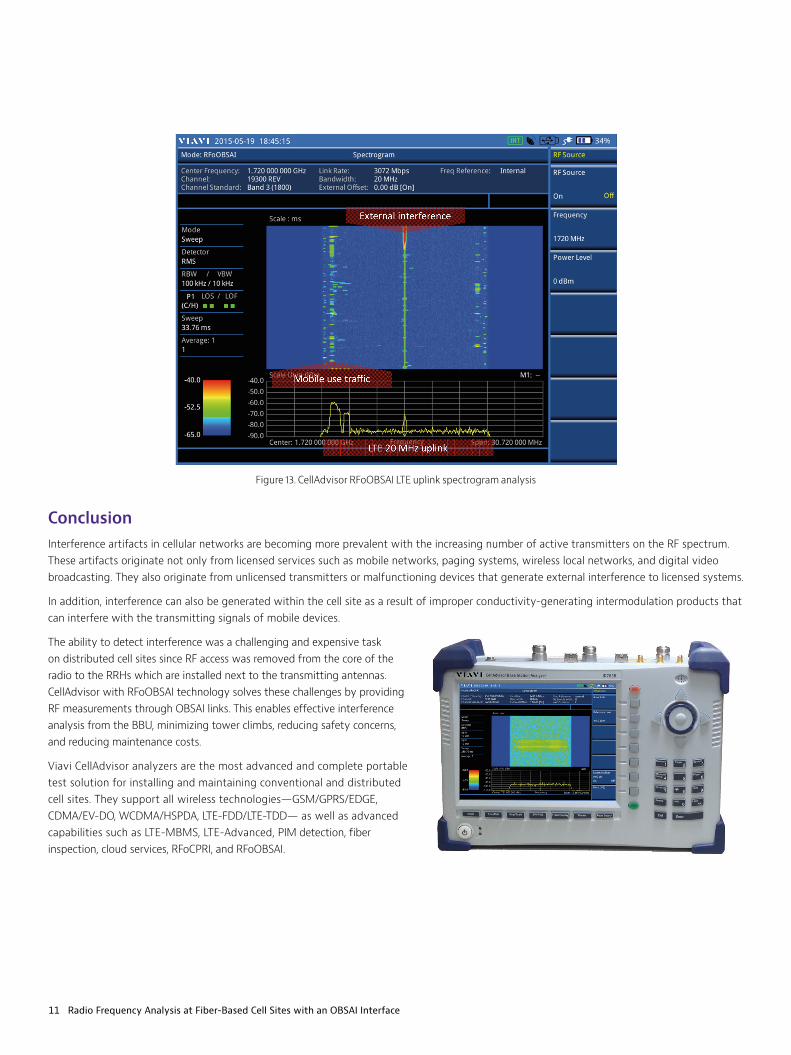
Figure 13. CellAdvisor RFoOBSAI LTE uplink spectrogram analysis
ConclusionInterference artifacts in cellular networks are becoming more prevalent with the increasing number of active transmitters on the RF spectrum. These artifacts originate not only from licensed services such as mobile networks, paging systems, wireless local networks, and digital video broadcasting. They also originate from unlicensed transmitters or malfunctioning devices that generate external interference to licensed systems.
In addition, interference can also be generated within the cell site as a result of improper conductivity-generating intermodulation products that can interfere with the transmitting signals of mobile devices.
The ability to detect interference was a challenging and expensive task on distributed cell sites since RF access was removed from the core of the radio to the RRHs which are installed next to the transmitting antennas. CellAdvisor with RFoOBSAI technology solves these challenges by providing RF measurements through OBSAI links. This enables effective interference analysis from the BBU, minimizing tower climbs, reducing safety concerns, and reducing maintenance costs.
Viavi CellAdvisor analyzers are the most advanced and complete portable test solution for installing and maintaining conventional and distributed cell sites. They support all wireless technologies—GSM/GPRS/EDGE, CDMA/EV-DO, WCDMA/HSPDA, LTE-FDD/LTE-TDD— as well as advanced capabilities such as LTE-MBMS, LTE-Advanced, PIM detection, fiber inspection, cloud services, RFoCPRI, and RFoOBSAI.

© 2015 Viavi Solutions Inc. Product specifications and descriptions in this document are subject to change without notice. rfoobsai-wp-nsd-nse-ae 30179558 000 1015
Contact Us +1 844 GO VIAVI (+1 844 468 4284)
To reach the Viavi office nearest you, visit viavisolutions.com/contacts.
viavisolutions.com
References y OBSAI BTS System Reference Document Version 2.0
y OBSAI Reference Point 3 Specification Version 4.2
Related Documents