White Paper www.jdsu.com/nse Radio equipment at conventional cell sites is located at the base of the tower, transmitting RF signals via coax to antennas at the top of the tower. However, these coax-based feeders produce most problems in cell sites due to their inherent loss and susceptibility to interference. In addition, environmental conditions deteriorate cables and connectors, creating signal reflections and intermodulation. Modern cell sites have a distributed architecture where the radio is divided into two main elements. A baseband unit (BBU) or radio equipment control (REC) performing radio functions on a digital baseband domain resides at the base of the tower; and, a remote radio head (RRH) or radio equipment (RE) performing radio frequency (RF) functions on an analog domain are installed next to the antennas at the top of the tower. These two radio elements, the BBU and RRH, communicate via a standard interface such as the common public radio interface (CPRI). Figure 1. Conventional and distributed cell sites Radio Frequency Analysis at Fiber-Based Cell Sites BBU Fiber feeder Antennas RRH Backhaul RADIO Coax feeder Antennas Backhaul Conventional cell site Distributed cell site

Welcome message from author
This document is posted to help you gain knowledge. Please leave a comment to let me know what you think about it! Share it to your friends and learn new things together.
Transcript
White Paperwww.jdsu.com/nse
Radio equipment at conventional cell sites is located at the base of the tower, transmitting RF signals via coax to antennas at the top of the tower. However, these coax-based feeders produce most problems in cell sites due to their inherent loss and susceptibility to interference. In addition, environmental conditions deteriorate cables and connectors, creating signal reflections and intermodulation.
Modern cell sites have a distributed architecture where the radio is divided into two main elements. A baseband unit (BBU) or radio equipment control (REC) performing radio functions on a digital baseband domain resides at the base of the tower; and, a remote radio head (RRH) or radio equipment (RE) performing radio frequency (RF) functions on an analog domain are installed next to the antennas at the top of the tower.
These two radio elements, the BBU and RRH, communicate via a standard interface such as the common public radio interface (CPRI).
Figure 1. Conventional and distributed cell sites
Radio Frequency Analysis at Fiber-Based Cell Sites
BBU
Fiberfeeder
Antennas RRH
Backhaul
RADIO
Coaxfeeder
Antennas
Backhaul
Conventional cell site Distributed cell site

2
Radio Frequency Analysis at Fiber-Based Cell Sites
www.jdsu.com/nse
Industry Standards
CPRI is an industry standard aimed at defining a publicly available specification for the internal interface of wireless base stations between the BBU and RRH. The parties cooperating to define the specification are Ericsson, Huawei, NEC, Alcatel Lucent, and Nokia Siemens Networks [1].
A similar specification was developed by the Open Base Station Architecture Initiative (OBSAI) which defines a set of specifications providing the architecture, function descriptions, and minimum requirements for integrating common modules into a base transceiver station (BTS). More specifically, reference point 3 (RP3) interchanges user and signaling data between the BBU and the RRH. The main network-element manufacturer members of OBSAI include ZTE, NEC, Nokia Siemens Networks, Samsung, and Alcatel Lucent [2].
In addition to CPRI and OBSAI, the European Telecommunications Standards Institute (ETSI) has defined the open radio equipment interface (ORI) to eliminate proprietary implementations and achieve interoperability between multi-vendor BBUs and RRHs. ORI specifications are based on CPRI and expand on the specifications of the interface.
Testing Distributed Cell Sites
A distributed cell site architecture provides the benefit of replacing coax-based feeders with fiber-based feeders. This significantly reduces signal loss and reflections. However, since all RF functions reside on the RRH, any RF maintenance or troubleshooting such as interference analysis requires reaching the top of the tower to get access to the RRH. This represents a higher operational expense and security concern.
These new test challenges for distributed cell sites add to existing testing requirements since the radio access network is a mix of conventional and distributed cell sites. An effective test solution must consolidate installation and maintenance tests:
• Cell site installation requires verification tests for coax-based feeders related to signal reflection including return loss or voltage standing wave ratios (VSWR), distance to fault and RF transmitted power; and, for fiber-based feeders, optical and fiber metrics including optical transmitted power and fiber inspection tests
• Cell site maintenance, in addition to requiring the same verification tests performed during installation, needs conformance tests related to signal integrity including RF characteristics, interference analysis, and modulation quality to ensure quality of service
JDSU has been working closely with mobile service providers to create CellAdvisor™, a comprehensive test solution for installating and maintaining cell sites. It is an integrated solution capable of characterizing both RF and fiber and tests signal quality to ensure quality of experience for mobile users. And, it includes RF over CPRI (RFoCPRI™) technology which de-maps RF components from CPRI on the ground, reducing maintenance costs and minimizing security concerns.
CPRI
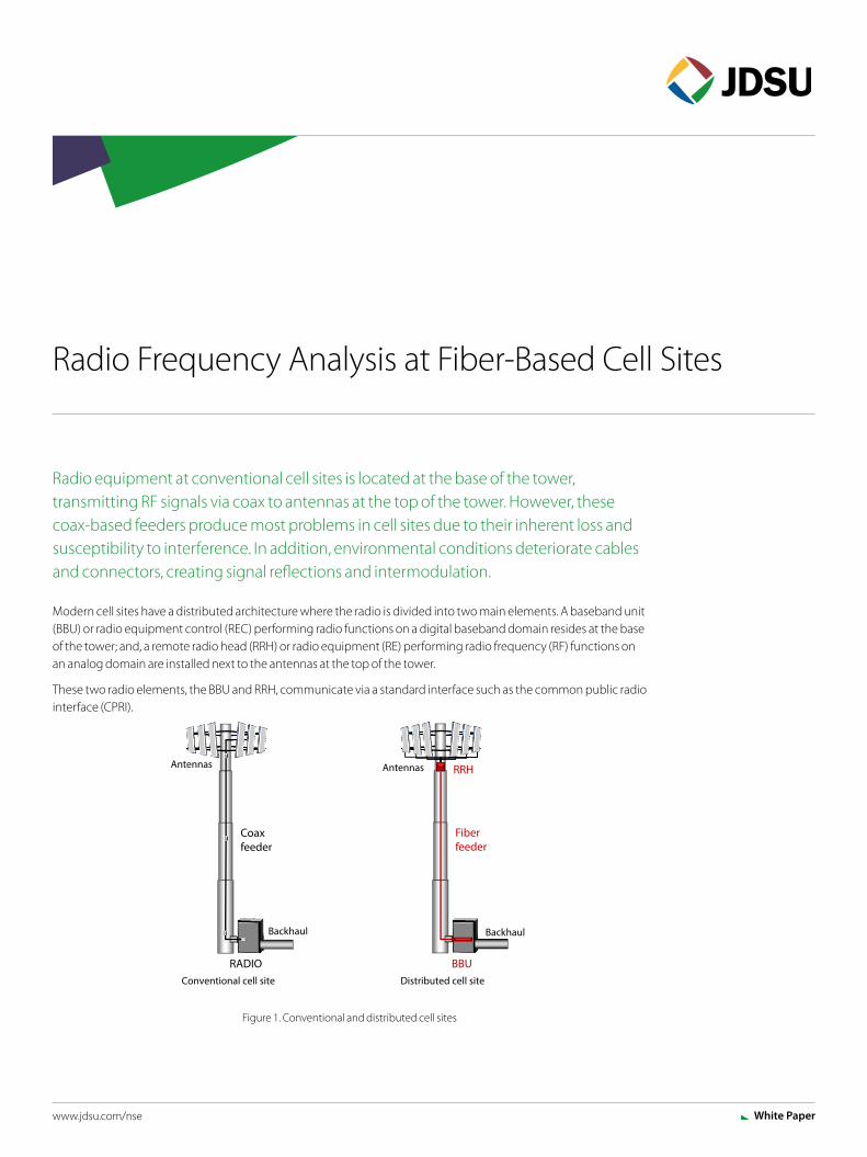
CPRI defines a specification for the interface between the BBU and the RRH to enable independent technology evolution of each element and flexibility of cell site architectures to serve macro cells, small cells, distributed antenna systems, and cloud radio access networks. It defines a serialized interface for different topologies such as chain, tree, and ring.
Figure 3. Chain topology
Figure 2. CellAdvisor with RFoCPRI
BBU
RRH
CPRI
BackhaulAntennasRRH
Antennas
CPRI
3
Radio Frequency Analysis at Fiber-Based Cell Sites
www.jdsu.com/nse
Figure 4. Tree topology
Figure 5. Ring topology
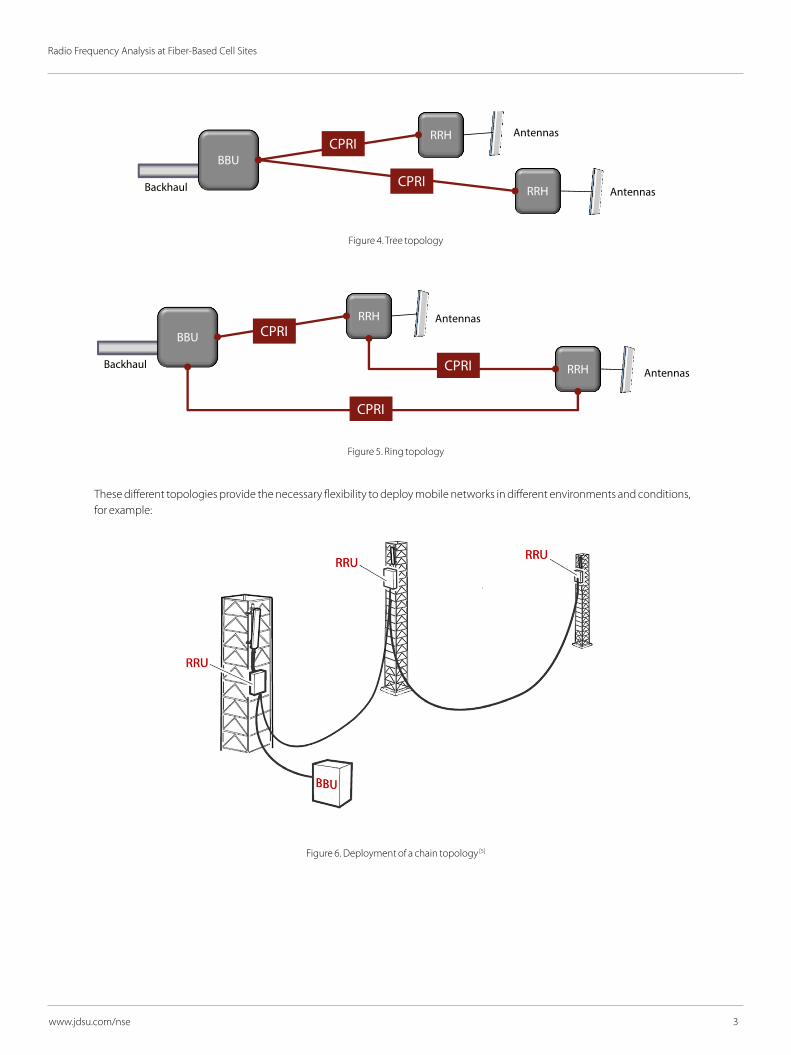
These different topologies provide the necessary flexibility to deploy mobile networks in different environments and conditions, for example:
Figure 6. Deployment of a chain topology [5]
BBU
RRHCPRI
Backhaul AntennasRRHCPRI
Antennas
BBU
RRHCPRI
BackhaulAntennasRRH
CPRI
Antennas
CPRI
4
Radio Frequency Analysis at Fiber-Based Cell Sites
www.jdsu.com/nse
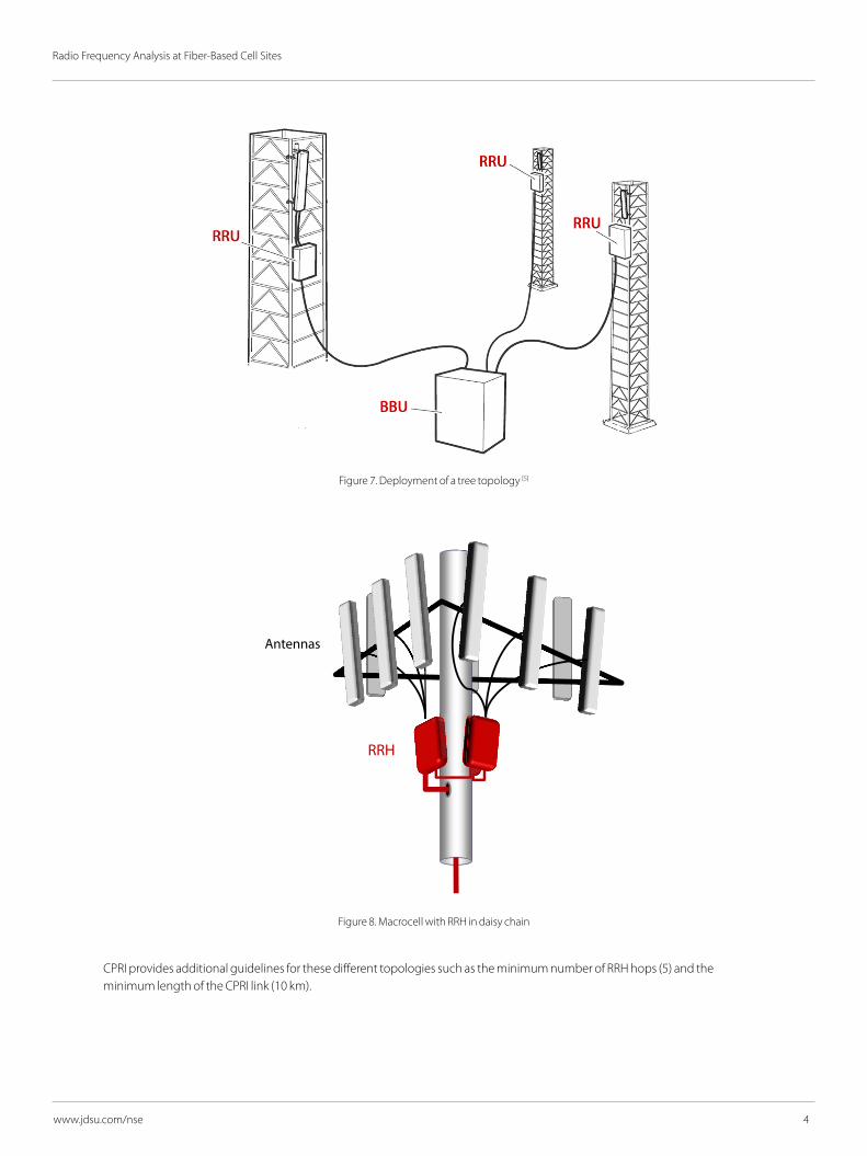
Figure 7. Deployment of a tree topology [5]
Figure 8. Macrocell with RRH in daisy chain
CPRI provides additional guidelines for these different topologies such as the minimum number of RRH hops (5) and the minimum length of the CPRI link (10 km).
Antennas
RRH
5
Radio Frequency Analysis at Fiber-Based Cell Sites
www.jdsu.com/nse
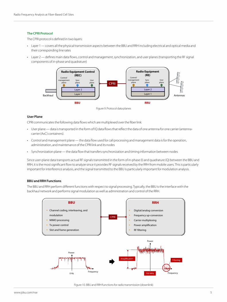
The CPRI Protocol
The CPRI protocol is defined in two layers:
• Layer 1 — covers all the physical transmission aspects between the BBU and RRH including electrical and optical media and their corresponding line rates
• Layer 2 — defines main data flows, control and management, synchronization, and user planes (transporting the RF signal components of in-phase and quadrature)
Figure 9. Protocol data planes
User Plane
CPRI communicates the following data flows which are multiplexed over the fiber link:
• User plane — data is transported in the form of IQ data flows that reflect the data of one antenna for one carrier (antenna-carrier (AxC) containers).
• Control and management plane — the data flow used for call processing and management data is for the operation, administration, and maintenance of the CPRI link and its nodes
• Synchronization plane — the data flow that transfers synchronization and timing information between nodes
Since user-plane data transports actual RF signals transmitted in the form of in-phase (I) and quadrature (Q) between the BBU and RRH, it is the most significant flow to analyze since it provides RF signals received by the RRH from mobile users. This is particularly important for interference analysis, and the signal transmitted to the BBU is particularly important for modulation analysis.
BBU and RRH Functions
The BBU and RRH perform different functions with respect to signal processing. Typically, the BBU is the interface with the backhaul network and performs signal modulation as well as administration and control of the RRH.
Figure 10. BBU and RRH functions for radio transmission (downlink)
Radio Equipment (RE)
CPRI
Radio Equipment Control(REC)
Layer 2
Layer 1
Control/management
planeSyncplane
Userplane
Backhaul Antennas
URRUBB
Backhaul
Layer 2
Layer 1
Control/management
planeSyncplane
Userplane
Radio Equipment(RE)
Layer 2
Layer 1
Control/management
planeSyncplane
Userplane
BBU
Channel coding, interleaving, and
modulation
MIMO processing
Tx power control
Slot and frame generation
RRH
Digital/analog conversion
Frequency up-conversion
Carrier multiplexing
Power ampli�cation
RF �ltering
Power
Frequency0 Hz
Power
Frequency700 MHz
Ampli�cation Filtering
CPRI

6
Radio Frequency Analysis at Fiber-Based Cell Sites
www.jdsu.com/nse
The RRH is typically responsible for the air interface to mobile users and the corresponding RF processing including amplification, filtering, and frequency conversion.
Figure 11. BBU and RRH functions for radio reception (uplink)
Line Rates
CPRI defines several line rates based on UMTS (3.84 MHz) to provide the flexibility to accommodate different signal bandwidths. For example, the first line rate option is defined as 614.4 Mbps (160 x 3.84 Mbps).
The line rate option defines the number of CPRI words that can be transmitted over the link, and therefore the user plane bandwidth or the amount of IQ data (RF signal) that can be supported.
Electrical and optical interfaces are supported by CPRI; however, most implementations have been done with optical interfaces, perhaps due to its properties of immunity to interference and minimal loss, its cost, and its ability to support high bandwidth.
Link Maintenance
CPRI has defined four key measurements related to link maintenance:
• Loss of signal (LOS) — ability to detect and indicate loss of signal
• Loss of frame (LOF) — ability to detect and indicate loss of frame including frame synchronization
• Remote Alarm Indication (RAI) — ability to indicate a remote alarm returned to the sender as a response to link errors (LOS and LOF)
• SAP defect indication (SDI) — ability to send remote indication when any of the service access points are not valid due to an equipment error
If any of the above alarms occur, an alarm indication is transmitted over the CPRI link to the remote element. It is therefore essential for any condition to ensure there are no alarms present and that the optical level is above the specified threshold of the BBU and/or RRH (for example, −20 dBm).
CPRI link maintenance measurements are the basic set of metrics used to assess link status, and user plane tests can be conducted once the link is properly operating without any alarms.
RRH
Frequency down-conversion
Automatic gain control
Carrier de-multiplexing
RF �ltering
Analog/digital conversion
BBU
Channel decoding, de-interleaving,
demodulation
MIMO processing
Transmit power control
Signal distribution for processing
Power
Frequency700 MHz
Power
Frequency0 Hz
Ampli�cation Filtering
CPRI
Table 1. CPRI line rates
Options Rate (Mbps)1 614.42 1228.83 2457.64 3072.05 4915.26 6144.07 9830.48 10137.6
Figure 12. Link maintenance measurements

7
Radio Frequency Analysis at Fiber-Based Cell Sites
www.jdsu.com/nse
CPRI Frame Structure
The creation of CPRI frames from an analog signal can be described in four stages: sampling, mapping, grouping, and framing. These processes are the basis of RF over CPRI transmission and RFoCPRI technology.
Figure 13. CPRI frame structure process
Sampling
RF signals are analyzed considering both I and Q components. These components are sampled and characterized digitally based on the number of bits assigned to represent this information (also referred as sampling bits).
The sampling rate per AxC is a multiple integer of 3.84 MHz. If signals do not equate to a multiple integer, stuffing samples are added.
CPRI defines the number of sample bits for uplink (M) and for downlink (M’) which range from 4 to 20 bits and 8 to 20 bits respectively
Figure 14. Sampling process
ACG-1 ACG ACG+N
Bn Sn Sn: IQ samples, Bn: stu�ng bits
AxC values: 4, 6, 8, 12, 18, 24
IQ sample width: Downlink: 8 to 20 bits Uplink: 4 to 20 bits
Ctrl IQ data block
Bytes: 1 2 … …16
r r r : Packed or �exible(reserved bits)
●●●
Basic frames (K)
Sn
AxC-0 AxC-1
1
Mapping
Bn
Sampling
Grouping
Framing
Analog (RF) signal
RF signal (RF)
CPRI link
Framing
Grouping
Mapping
Sampling
Frequency
Power
Table 2. Sampling parameters
Link Type Sample ID RangeUplink M 4 to 20
Downlink M’ 8 to 20
Power
Frequency
I
Q
SamplingI0
Q0
I1
Q1
I2
Q2
I3
Q3
IM-1
QM-1
Modulationdomain
3.84 Mbps : AXC
M: sampling bits
Frequencydomain
NST
NST
N: stu�ng bits

8
Radio Frequency Analysis at Fiber-Based Cell Sites
www.jdsu.com/nse
Mapping
The I and Q samples are consecutively mapped in chronological order and consecutively into containers defined as antenna-carrier (AxC) containers and are transported by only one carrier at one independent antenna.
CPRI defines 3 mapping methods: (1) IQ sample based, (2) WiMAX symbol based, and (3) backwards compatible. The most applicable mapping methods in mobile networks are IQ sample based and backwards compatible, which are briefly described as follows:
• IQ sample based — intended for dense packing of IQ data and low latency. The size of the AxC is defined as NAxC = 2*Ceil ( ), where Ceil is the ceiling function, M is the number of sample bits, ƒs is the sampling rate and ƒc is the UMTS chip rate of 3.84 MHz.
• Backwards compatible — this methodology defines an AxC containing exactly one sample (or stuffing bits for LTE and GSM signals), therefore the size of an AxC is defined as 2*M where M is the number of sample bits.
The following illustrates the mapping process of an LTE 10 MHz signal with 15 sampling bits (M) that considers the CPRI recommendation of a sampling rate of 15.36 (or 4 x chip rate of 3.84 MHz) and no stuffing bits.
Figure 15. LTE 10 MHz mapping process
Table 3. Backwards compatible [1] mapping method
Backwards compatible mapping methodLTE channel BW (MHz) 3 5 10 15 20ƒS (sampling rate MHz) 3.84 7.68 15.36 23.04 30.72ƒC (chip rate 3.84 MHz) 1 2 4 6 8AxC containers, stuffing bits 1,0 2,0 4,0 6,0 8,0
M*ƒs
ƒc
Power
Frequency10 MHz
I14
Q14
AXC#13.84 Mbps
I0
Q0
15.36 MHz
Sampling
I29
Q29
AXC#23.84 Mbps
I15
Q15
I44
Q44
AXC#33.84 Mbps
I30
Q30
I59
Q59
AXC#43.84 Mbps
I45
Q45
MappingM = 15, Stu�ng = 0
9
Radio Frequency Analysis at Fiber-Based Cell Sites
www.jdsu.com/nse
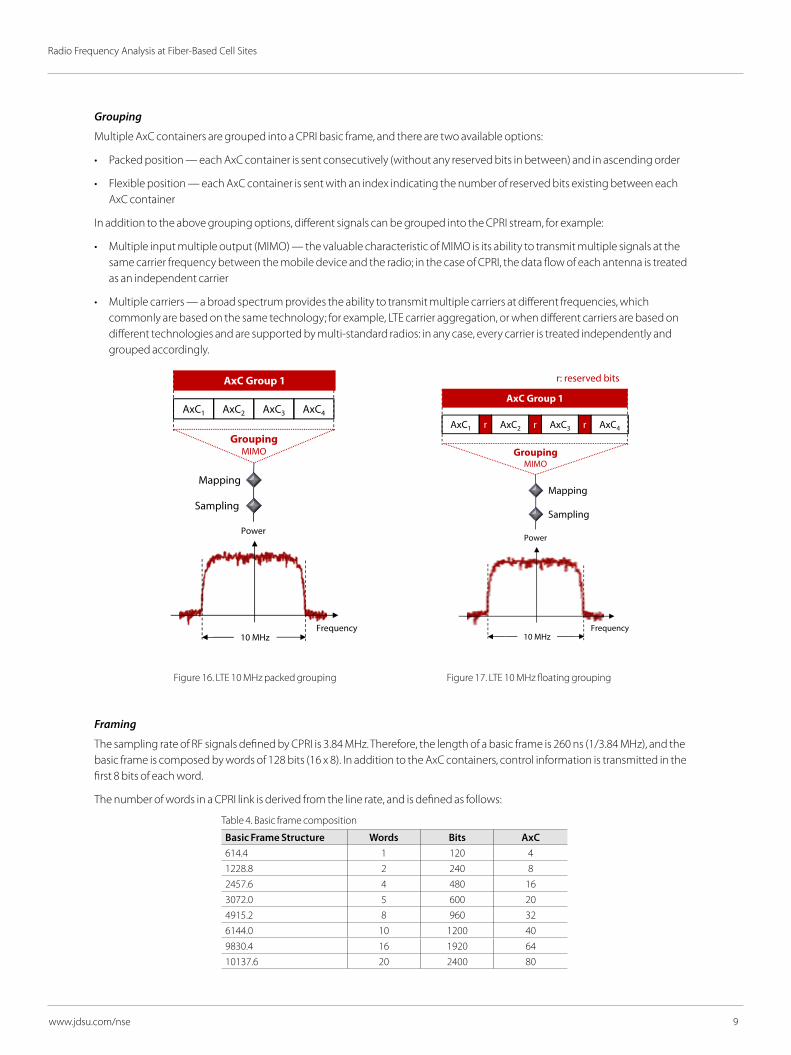
Grouping
Multiple AxC containers are grouped into a CPRI basic frame, and there are two available options:
• Packed position — each AxC container is sent consecutively (without any reserved bits in between) and in ascending order
• Flexible position — each AxC container is sent with an index indicating the number of reserved bits existing between each AxC container
In addition to the above grouping options, different signals can be grouped into the CPRI stream, for example:
• Multiple input multiple output (MIMO) — the valuable characteristic of MIMO is its ability to transmit multiple signals at the same carrier frequency between the mobile device and the radio; in the case of CPRI, the data flow of each antenna is treated as an independent carrier
• Multiple carriers — a broad spectrum provides the ability to transmit multiple carriers at different frequencies, which commonly are based on the same technology; for example, LTE carrier aggregation, or when different carriers are based on different technologies and are supported by multi-standard radios: in any case, every carrier is treated independently and grouped accordingly.
Framing
The sampling rate of RF signals defined by CPRI is 3.84 MHz. Therefore, the length of a basic frame is 260 ns (1/3.84 MHz), and the basic frame is composed by words of 128 bits (16 x 8). In addition to the AxC containers, control information is transmitted in the first 8 bits of each word.
The number of words in a CPRI link is derived from the line rate, and is defined as follows:
Power
Frequency10 MHz
Sampling
GroupingMIMO
Power
Frequency10 MHz
Sampling
Mapping Mapping
AxC1
AxC Group 1
GroupingMIMO
AxC Group 1
rAxC2 AxC3 AxC4 AxC1 AxC2 AxC3 AxC4r r
Power
Frequency10 MHz
Sampling
Mapping
GroupingMIMO
AxC Group 1
rAxC1 AxC2 AxC3 AxC4r r
r: reserved bits
Figure 16. LTE 10 MHz packed grouping Figure 17. LTE 10 MHz floating grouping
Table 4. Basic frame composition
Basic Frame Structure Words Bits AxC614.4 1 120 41228.8 2 240 82457.6 4 480 163072.0 5 600 204915.2 8 960 326144.0 10 1200 409830.4 16 1920 6410137.6 20 2400 80
10
Radio Frequency Analysis at Fiber-Based Cell Sites
www.jdsu.com/nse
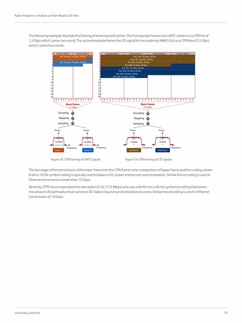
The following examples illustrate the framing of antennas and carriers. The first example frames two UMTS carriers on a CPRI link of 1.2 Gbps which carries two words. The second example frames the LTE signal for two antennas MIMO (2x) on a CPRI link of 2.5 Gbps which carries four words.
The last stage of the transmission of the basic frame into the CPRI frame is the composition of hyper-frame and line coding, where 8-bit to 10-bit symbol coding is typically used to balance DC power and recover synchronization. Similar line encoding is used in Ethernet transmissions lower than 10 Gbps.
Recently, CPRI has incorporated line rate option 8 (10,137.6 Mbps) and uses a 64-bit into a 66-bit symbol encoding that lowers the amount of overhead and yet achieves DC balancing and synchronization recovery. Similar line encoding is used in Ethernet transmission of 10 Gbps.
0 Control Byte 0 Control Byte 11 AxC Group 0, IQ data, 30 bits23 AxC Group 1, IQ data, 30 bits456789
101112131415
A B C D E F G H A B C D E F G H
Power
Carrier 1
Power
Carrier 2
Sampling
Basic frame1.2 Gbps
Mapping
Grouping
Power Power
Sampling
Basic frame2.4 Gbps
Mapping
Grouping
Antenna 1 Antenna 2
0 Control Byte 0 Control Byte 1 Control Byte 2 Control Byte 31 AxC 0 #1, IQ data, 30 bits2 AxC 0 #2, IQ data, 30 bits3 AxC 0#3, IQ data, 30 bits4 AxC 0#4, IQ data, 30 bits5 AxC 1#1, IQ data, 30 bits6 AxC 1#2, IQ data, 30 bits7 AxC 1#3, IQ data, 30 bits8 AxC 1#4, IQ data, 30 bits9
101112131415
A B C D E F G H A B C D E F G H A B C D E F G H A B C D E F G H
3.8 MHz 3.8 MHz 10 MHz 10 MHz
FrequencyFrequency Frequency Frequency
Figure 18. CPRI framing of UMTS signals Figure 19. CPRI framing of LTE signals
11
Radio Frequency Analysis at Fiber-Based Cell Sites
www.jdsu.com/nse
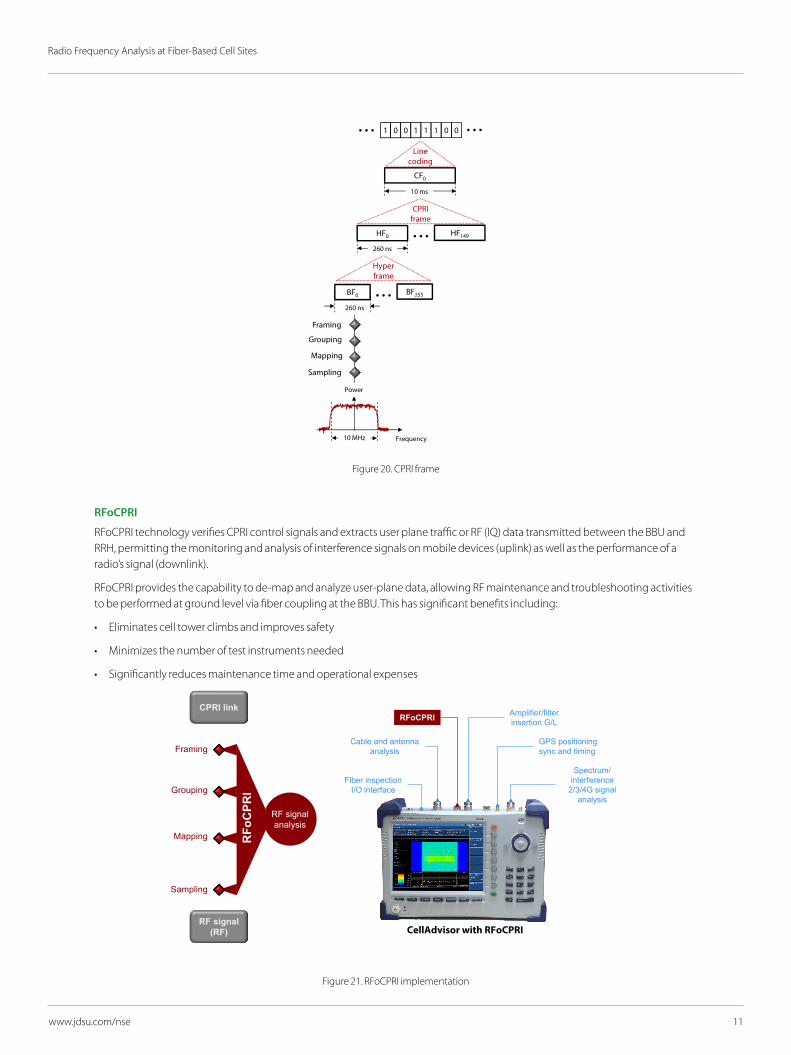
Figure 20. CPRI frame
RFoCPRI
RFoCPRI technology verifies CPRI control signals and extracts user plane traffic or RF (IQ) data transmitted between the BBU and RRH, permitting the monitoring and analysis of interference signals on mobile devices (uplink) as well as the performance of a radio’s signal (downlink).
RFoCPRI provides the capability to de-map and analyze user-plane data, allowing RF maintenance and troubleshooting activities to be performed at ground level via fiber coupling at the BBU. This has significant benefits including:
• Eliminates cell tower climbs and improves safety
• Minimizes the number of test instruments needed
• Significantly reduces maintenance time and operational expenses
Figure 21. RFoCPRI implementation
RFo
CPR
I
Cable and antennaanalysis
Spectrum/interference
2/3/4G signal analysis
Amplifier/filterinsertion G/L
GPS positioning sync and timing
Fiber inspectionI/O interface
RFoCPRI
RF signal (RF)
CPRI link
Framing
Grouping
Mapping
Sampling
RF signal analysis
CellAdvisor with RFoCPRI
Sampling
Mapping
Grouping
Framing
BF0 BF255
Hyper frame
HF0
260 ns
260 ns
HF149
CPRIframe
CF0
10 ms
Power
Frequency10 MHz
Line coding
1 0 0 1 1 1 0 0
12
Radio Frequency Analysis at Fiber-Based Cell Sites
www.jdsu.com/nse
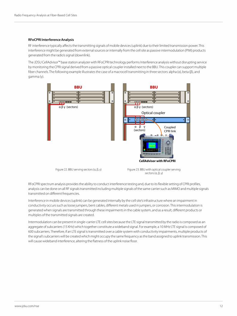
RFoCPRI Interference Analysis
RF interference typically affects the transmitting signals of mobile devices (uplink) due to their limited transmission power. This interference might be generated from external sources or internally from the cell site as passive intermodulation (PIM) products generated from the radio’s signal (downlink).
The JDSU CellAdvisor™ base station analyzer with RFoCPRI technology performs Interference analysis without disrupting service by monitoring the CPRI signal derived from a passive optical coupler installed next to the BBU. This coupler can support multiple fiber channels. The following example illustrates the case of a macrocell transmitting in three sectors: alpha (α), beta (β), and gamma (γ).
RFoCPRI spectrum analysis provides the ability to conduct interference testing and, due to its flexible setting of CPRI profiles, analysis can be done on all RF signals transmitted including multiple signals of the same carrier such as MIMO and multiple signals transmitted on different frequencies.
Interference in mobile devices (uplink) can be generated internally by the cell site’s infrastructure where an impairment in conductivity occurs such as loose jumpers, bent cables, different metals used in jumpers, or corrosion. This intermodulation is generated when signals are transmitted through these impairments in the cable system, and as a result, different products or multiples of the transmitted signals are created.
Intermodulation can be present in single-carrier LTE cell sites because the LTE signal transmitted by the radio is composed as an aggregate of subcarriers (15 KHz) which together constitute a wideband signal. For example, a 10 MHz LTE signal is composed of 600 subcarriers. Therefore, if an LTE signal is transmitted over a cable system with conductivity impairments, multiple products of the signal’s subcarriers will be created which might occupy the same frequency as the band assigned to uplink transmission. This will cause wideband interference, altering the flatness of the uplink noise floor.
BBUBBU
α β γ
α β γ
(sectors)
(sectors)
Optical coupler
α β γ (sectors)
Coupled CPRI link
CellAdvisor with RFoCPRI
Figure 22. BBU serving sectors (α, β, γ) Figure 23. BBU with optical coupler serving sectors (α, β, γ)

13
Radio Frequency Analysis at Fiber-Based Cell Sites
www.jdsu.com/nse
The following RFoCPRI spectrum analysis example is from a cell site transmitting LTE signals of 10 MHz over two antennas (MIMO) where the uplink branches are exhibiting a power imbalance.
Figure 24. RFoCPRI spectrum analysis — LTE uplink 10 MHz MIMO with intermodulation
In addition to the higher power level exhibited by antenna 1, with respect to the power level of antenna 0, its power level is higher at lower frequencies and gradually decreases with lower frequencies. This is a key characteristic of intermodulation.
Interference from external sources to the cell site can also be detected by spectrum analysis. However, due to the different nature and unique characteristics of interferers, the parameters of the spectrum analysis must be properly adjusted. These parameters include filtering (resolution, bandwidth, and video bandwidth), power adjustments that include attenuation and averaging and pre-amplification for effective interference detection and analysis.
External interferences are often only active for shorts periods of time, making them difficult to detect. In this case, it is important to continuously record spectrum measurements, either as spectrum analysis or spectrogram measurements.
Spectrogram measurements are perhaps the most common technique used to detect intermittent interference. One can continuously monitor and record the spectrum through time, seeing power variations with different color codes. This enables the capture of spectral characteristics through time, detecting intermittent interferences.
The following RFoCPRI spectrogram example shows an intermittent interferer with frequency hopping across an LTE uplink.
Figure 25. RFoCPRI spectrogram measurement with intermittent interference

14
Radio Frequency Analysis at Fiber-Based Cell Sites
www.jdsu.com/nse
Interference is a significant problem for mobile transmission (uplink) regardless of the type of cell site that is providing service. For example, interference can be present in metropolitan areas where small cells or cloud radio access networks are mostly deployed, as well as in venues such as stadiums or shopping malls where distributed antenna systems are commissioned and macrocells serving urban and suburban areas.
Figure 26. Small cell and CellAdvisor with RFoCPRI
Figure 27. Distributed antenna system (DAS) and CellAdvisor with RFoCPRI
15
Radio Frequency Analysis at Fiber-Based Cell Sites
www.jdsu.com/nse
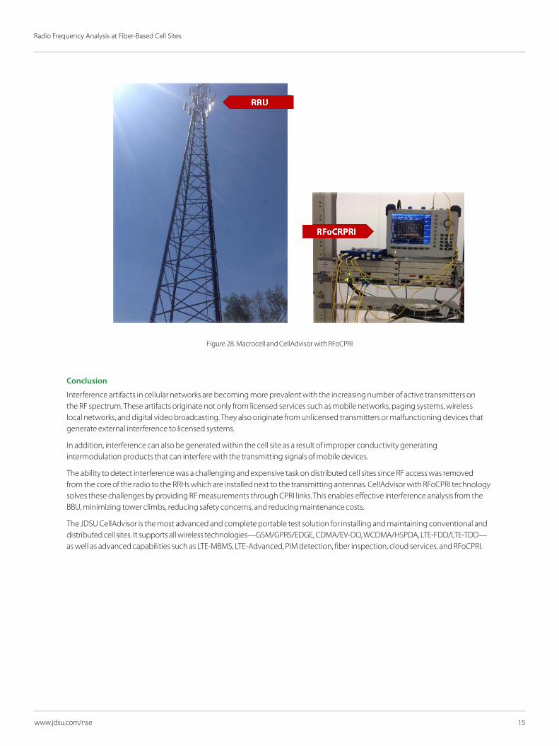
Figure 28. Macrocell and CellAdvisor with RFoCPRI
Conclusion
Interference artifacts in cellular networks are becoming more prevalent with the increasing number of active transmitters on the RF spectrum. These artifacts originate not only from licensed services such as mobile networks, paging systems, wireless local networks, and digital video broadcasting. They also originate from unlicensed transmitters or malfunctioning devices that generate external interference to licensed systems.
In addition, interference can also be generated within the cell site as a result of improper conductivity generating intermodulation products that can interfere with the transmitting signals of mobile devices.
The ability to detect interference was a challenging and expensive task on distributed cell sites since RF access was removed from the core of the radio to the RRHs which are installed next to the transmitting antennas. CellAdvisor with RFoCPRI technology solves these challenges by providing RF measurements through CPRI links. This enables effective interference analysis from the BBU, minimizing tower climbs, reducing safety concerns, and reducing maintenance costs.
The JDSU CellAdvisor is the most advanced and complete portable test solution for installing and maintaining conventional and distributed cell sites. It supports all wireless technologies—GSM/GPRS/EDGE, CDMA/EV-DO, WCDMA/HSPDA, LTE-FDD/LTE-TDD—as well as advanced capabilities such as LTE-MBMS, LTE-Advanced, PIM detection, fiber inspection, cloud services, and RFoCPRI.
Radio Frequency Analysis at Fiber-Based Cell Sites
© 2015 JDS Uniphase Corporation Product specifications and descriptions in this document are subject to change without notice. 30176040 001 0115 RFOCPRI.WP.NSD.NSE.AE January 2015
www.jdsu.com/nse
North America Toll Free: 1 855 ASK-JDSU (1 855 275-5378)Latin America Tel: +1 954 688 5660 Fax: +1 954 345 4668Asia Pacific Tel: +852 2892 0990 Fax: +852 2892 0770EMEA Tel: +49 7121 86 2222 Fax: +49 7121 86 1222
References
1. Common Public Radio Interface (CPRI); Interface Specification V6.0
2. Open Base Station Architecture Initiative (OBSAI) – BTS System Reference Document Version 2.0
3. ETSI GS ORI 001. Open Radio Equipment Interface (ORI); Requirements for Open Radio Equipment Interface (ORI)
4. ETSI GS ORI 002. Open Radio Equipment Interface (ORI); ORI Interface Specification; Part 1: Low Layers
5. Remote Radio Unit Description by Ericsson.
6. Interference in Cellular Networks; Intermodulation and Frequency Refarming by JDSU.
7. Radio Access Networks; Interference Analysis by JDSU.
Related Documents