NTIA Technical Memorandum TM-05-426 Radiation Pattern Analysis of a Four-Element Linear Array John J. Lemmon

Welcome message from author
This document is posted to help you gain knowledge. Please leave a comment to let me know what you think about it! Share it to your friends and learn new things together.
Transcript
NTIA Technical Memorandum TM-05-426
Radiation Pattern Analysisof a Four-Element Linear Array
John J. Lemmon


NTIA Technical Memorandum TM-05-426
Radiation Pattern Analysisof a Four-Element Linear Array
John J. Lemmon
U.S. DEPARTMENT OF COMMERCE
Carlos M. Gutierrez, Secretary
Michael D. Gallagher, Assistant Secretaryfor Communications and Information
July 2005


iii
DISCLAIMER
Certain commercial equipment, software, or materials are identified in this report to specify thetechnical aspects of the reported results. In no case does such identification implyrecommendation or endorsement by the National Telecommunications and InformationAdministration, nor does it imply that the material or equipment identified is necessarily the bestavailable for the purpose.


v
CONTENTS
Page
1. INTRODUCTION AND BACKGROUND . . . . . . . . . . . . . . . . . . . . . . . . . . . . . . . . . . . . . . . 1
2. MEASUREMENT SYSTEM . . . . . . . . . . . . . . . . . . . . . . . . . . . . . . . . . . . . . . . . . . . . . . . . . 2
3. DATA ANALYSIS . . . . . . . . . . . . . . . . . . . . . . . . . . . . . . . . . . . . . . . . . . . . . . . . . . . . . . . . . 4
4. RADIATION PATTERN OF A FOUR-ELEMENT ARRAY . . . . . . . . . . . . . . . . . . . . . . . . 8
5. MUTUAL COUPLING . . . . . . . . . . . . . . . . . . . . . . . . . . . . . . . . . . . . . . . . . . . . . . . . . . . . . 10
6. CONCLUSIONS AND RECOMMENDATIONS . . . . . . . . . . . . . . . . . . . . . . . . . . . . . . . . 14
7. REFERENCES . . . . . . . . . . . . . . . . . . . . . . . . . . . . . . . . . . . . . . . . . . . . . . . . . . . . . . . . . . . 15


The author is with the Institute for Telecommunication Sciences, National Telecommunications and1
Information Administration, U.S. Department of Commerce, Boulder, CO 80305.
P. Wilson and P. Papazian, private communication.2
RADIATION PATTERN ANALYSIS OF A FOUR-ELEMENT LINEAR ARRAY
John J. Lemmon1
The effects of mutual coupling on the radiation pattern of a four-element lineararray were investigated. The objective was to improve the angular resolution ofthe array for direction-of-arrival estimation by compensating for mutual coupling.It is concluded that the effects of mutual coupling on the performance of the arrayare not significant, and that the angular resolution of the array is consistent withits theoretical radiation pattern in the absence of mutual coupling. However, it isrecommended that the array be calibrated to compensate for systematic errors andany (small) mutual coupling effects that are present.
Key words: direction-of-arrival (DOA); linear array; mutual coupling
1. INTRODUCTION AND BACKGROUND
Several years ago Wilson and Papazian described direction-of-arrival (DOA) measurementsusing a four-element linear array [1]. Although the results demonstrate that their measurementsystem is indeed capable of determining the DOA of received signals, the authors expected thesystem to have better angular resolution than that inferred from angular power spectra developedfrom the measured data. They further speculated that the relatively poor angular resolution was2
due to mutual coupling among the antenna elements.2
The purpose of the present study was to investigate the effects of mutual coupling on theradiation pattern of the antenna array used for these measurements and to determine how theseeffects could be taken into account in DOA estimation using measured data. The objective was toobtain better angular resolution of the DOA of received signals in angular power spectra bycompensating for mutual coupling.
This report is organized as follows. Sections 2 and 3 briefly describe the measurement systemand DOA estimation techniques used to collect and analyze the data presented in [1]. Section 4discusses the theoretical radiation pattern for the four-element array that one expects in theabsence of mutual coupling. This is followed in Section 5 by a discussion of mutual couplingeffects and the feasibility of compensating for mutual coupling in DOA estimation using eithermodeling or measured data. Section 6 presents conclusions and recommendations for futureDOA measurements, should such measurements be undertaken.

2
Figure 1. Examples of measured impulses.
2. MEASUREMENT SYSTEM
The data in [1] were collected with a digital channel probe (DCP). The DCP generates amaximal-length pseudonoise (PN) code that biphase modulates a radio frequency (RF) carrier.The signal is transmitted over the radio channel, and at the receiver the signal is downcoverted toan intermediate frequency, digitized, and further downconverted to baseband. The basebandsignal is cross-correlated with a copy of the transmitted PN code, thereby enabling one todevelop the complex, baseband impulse response of the radio transmission channel as a functionof time delay. System details are described in a previous report [2]. For these measurements theDCP was configured to transmit a 511-bit PN code at 10 Mb/s using a 1920 MHz RF carrier. Thereceived signal was sampled at 40 Mb/s. Figure 1 shows a calibration impulse and an example ofa received impulse; the received impulse shows the effect of multipath.
3
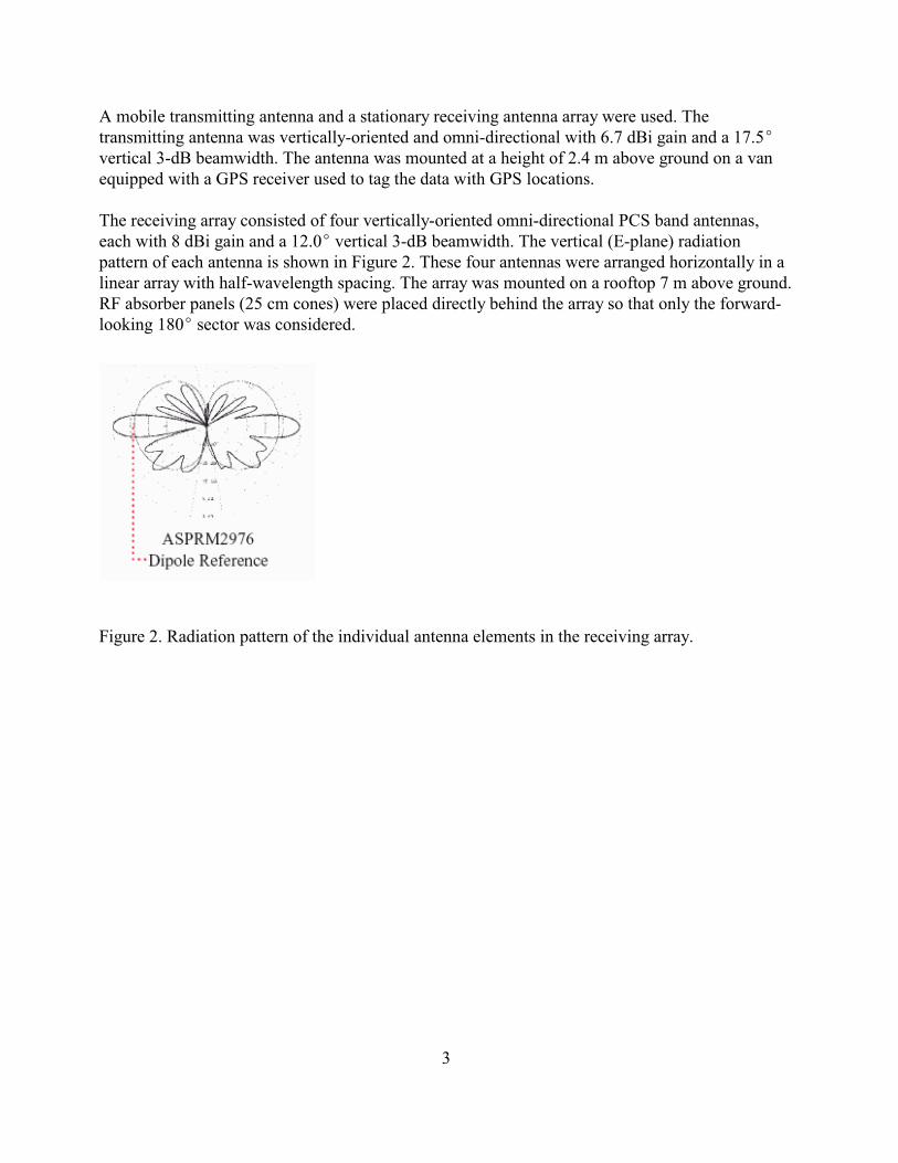
A mobile transmitting antenna and a stationary receiving antenna array were used. Thetransmitting antenna was vertically-oriented and omni-directional with 6.7 dBi gain and a 17.5Evertical 3-dB beamwidth. The antenna was mounted at a height of 2.4 m above ground on a vanequipped with a GPS receiver used to tag the data with GPS locations.
The receiving array consisted of four vertically-oriented omni-directional PCS band antennas,each with 8 dBi gain and a 12.0E vertical 3-dB beamwidth. The vertical (E-plane) radiationpattern of each antenna is shown in Figure 2. These four antennas were arranged horizontally in alinear array with half-wavelength spacing. The array was mounted on a rooftop 7 m above ground.RF absorber panels (25 cm cones) were placed directly behind the array so that only the forward-looking 180E sector was considered.
Figure 2. Radiation pattern of the individual antenna elements in the receiving array.

4
(1)
(2)
(3)
(4)
(5)
3. DATA ANALYSIS
The DOA estimates discussed in [1] were obtained from azimuth power spectra (APS) that weredeveloped from the impulse response data as follows. A direction-dependent weight vector w(è) isapplied to the impulse response vector of the array x(ô) to form a scalar y(è,ô):
where H denotes the Hermitian conjugate. The estimated power output P(è,ô) is given by
xxwhere * denotes the complex conjugate and R defines the autocorrelation matrix. Due to noiseand other uncertainties the autocorrelation matrix is not known precisely and was thereforeaveraged using the modified covariance method (MCM) to obtain a smoothed autocorrelation
MCMmatrix R [1].
The weight vectors used weights of equal magnitude with phase differences that correspond to thedelay for a plane wave incident from the pointing direction. The weight vector for a four-element,equally spaced, linear array is therefore
where è is the angle of an incident plane wave relative to the array axis, k is the wavenumber, andd is the element spacing. The DOA pattern is obtained by scanning the weight vector over a rangeof possible angles.
Two DOA estimation methods were considered in [1]: the parallelogram method (PM) and thenormalized maximum likelihood method (NMLM). The PM power density is estimated as
and the NMLM power density estimate is given by
These two power density estimates each define an azimuth delay power spectrum (ADPS) for themeasured data. The power delay profile, or delay power spectrum (DPS), and the azimuth powerspectrum (APS) are found by performing the appropriate integrations:

5
(6)
(7)
and
The mobile transmitter was driven through a suburban neighborhood, and 223 bursts consisting of16 impulses each were acquired with a spacing of 5 s between bursts. The 16 impulses in eachburst were averaged using MCM and an ADPS was calculated for each burst using both PM andNMLM. Figures 3 (PM) and 4 (NMLM) show an example ADPS, along with the associated APSamd DPS profiles, for the same burst. Both methods show significant multipath.
Figure 3. The PM estimated azimuthal delay power spectrum for a sample burst.
Figure 4. The NMLM estimated azimuthal delay power spectrum for a sample burst.

6
Figure 5 shows the DOA as determined by three different estimates. The GPS location of themobile can be used to determine the line-of-sight (LOS) angle. The maxima of the PM andNMLM APS profiles give two further estimates. Whereas the GPS DOA tracks the location of thevehicle, the APS DOA estimates may differ from the LOS value if significant multipath is present.Figure 5 shows a systematic offset of approximately 10E between the GPS LOS value and the twoAPS estimates. This suggests the presence of systematic errors due to unequal cable lengths orcontributions due to the antenna array or other hardware.
Figure 5. The DOA as determined by the GPS location, the maximum of the PM estimate, and themaximum of the NMLM estimate.
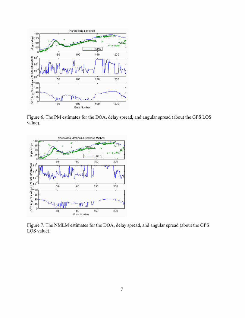
The DPS and APS profiles were used to calculate delay and azimuth spreads. Delay spread wascalculated about the mean in the usual way [2] using a 10-dB-below-peak cutoff value. Theazimuth spread was calculated about the GPS-determined LOS value using a 3-dB cutoff. Theresults for the PM and NMLM estimates are shown in Figures 6 and 7, respectively. In particular,note that the angular spreads vary between approximately zero and 90E or more.
7
Figure 6. The PM estimates for the DOA, delay spread, and angular spread (about the GPS LOSvalue).
Figure 7. The NMLM estimates for the DOA, delay spread, and angular spread (about the GPSLOS value).

8
(8)
(9)
(10)
(11)
(12)
4. RADIATION PATTERN OF A FOUR-ELEMENT ARRAY
Before discussing the effects of mutual coupling on the performance of the antenna array, it isworthwhile to consider the theoretical radiation pattern of the array in the absence of mutualcoupling. The normalized radiation pattern F(è,ö) of an array consisting of identical elements is[3]
where g(è,ö) is the (normalized) pattern of a single element (the element pattern) and f(è,ö) is the(normalized) pattern of an array of isotropic point sources with the same locations, amplitudes,and phases as the original array (the array factor).
The array in [1] used vertically-oriented omni-directional antennas arranged horizontally in alinear array. It follows that the radiation pattern in the horizontal plane is simply the array factor inthe horizontal plane. For an array of N equally spaced elements with a linear phase progression(the relative phase between adjacent elements is the same), the array factor is [3]
where
and the n+1 element leads the n element in phase by á.th th
With the radiation pattern of the array given by the above expression for f(ø), it can be shown that
0the direction è of the main beam depends on the element separation d and the phase progressioná, and that the angular width of the main beam depends on the array length Nd and the main beam
0pointing angle è . A common measure of the width of the main beam is the half-power beamwidth(HP). Approximate expressions (that become exact in the limit of very long arrays) for HP are [4]
and

9
These expressions imply that a four-element array with half-wavelength separation has a half-power beamwidth of approximately 25E near broadside and 76E at endfire. These relatively large beamwidths suggest that the broad APS profiles in Figures 3 and 4 and the 3-dB cutoff angularspreads in Figures 6 and 7 are due to the poor angular resolution of a four-element array and arenot due to a failure to compensate for mutual coupling. Moreover, the data contain significantmultipath, which may increase the angular spreads to values greater than the theoreticalbeamwidths.

10
(13)
(14)
5. MUTUAL COUPLING
In a real antenna array the elements interact with one another and alter the currents andimpedances from what would exist if the elements were isolated. This interaction, called mutualcoupling, changes the magnitude, phase, and distribution of current on each element and results ina total array radiation pattern that differs from the theoretical pattern in the no-coupling case.
The impedance effects of mutual coupling can be described by treating an array of N elements asan N-port network using conventional circuit analysis. The current-voltage relations are
n n nnwhere V and I are the impressed voltage and current, respectively, in the n element and Z isth
the self-impedance of the n element when all other elements are open-circuited. The mutualth
mn nmimpedance Z ( = Z by reciprocity) between the two elements m and n is the open-circuitvoltage produced at element m divided by the current supplied to element n when all otherelements are open-circuited. Mutual impedance is difficult to compute or measure in general. Thetechnique for measuring mutual impedance between two antennas is discussed in [3] and [4, pp.157-160], and can be generalized to determine the mutual impedance between any two elementsin an arbitrary array.
Closely related to the mutual and self impedances are the S-parameters, which have beenmeasured for the antenna array in [1] using a network analyzer described in [5]. The S-parametersprovide a means for characterizing an N-port network inserted in a transmission line. Forexample, consider the 2-port network (2-element array) inserted in a transmission line shown inFigure 8. The voltage and current along the transmission line can be considered to be in the formof traveling waves. Each of the four traveling waves is made up of a combination of two waves.
r2 i2For example, E is made up of that portion of E reflected from the output port of the network
i1and that portion of E that is transmitted through the network. The S-parameters relate thosewaves reflected from the network to those waves incident upon the network:

11
(15)
(16)
(17)
Figure 8. The four traveling waves resulting from the insertion of a two-port network in atransmission line.
On the other hand, the total voltage and total current on the transmission line are given by
and
0where Z is the characteristic impedance of the transmission line.
ij ijRelationships between the S-parameters S and the impedance matrix Z can be derived bysubstituting the expressions for total voltage (15) and total current (16) into the voltage-currentrelations (13) with N = 2 and rewriting the resulting equations in the form of (14). Equating the
i1 i2 ijcoefficients of E and E in these equations with the corresponding coefficients S in (14) impliesthat
and
12
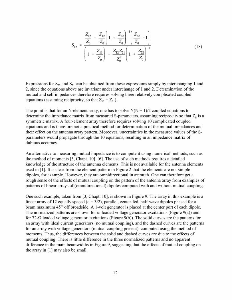
(18)
22 21Expressions for S and S can be obtained from these expressions simply by interchanging 1 and2, since the equations above are invariant under interchange of 1 and 2. Determination of themutual and self impedances therefore requires solving three relatively complicated coupled
12 21equations (assuming reciprocity, so that Z = Z ).
The point is that for an N-element array, one has to solve N(N + 1)/2 coupled equations to
ijdetermine the impedance matrix from measured S-parameters, assuming reciprocity so that Z is asymmetric matrix. A four-element array therefore requires solving 10 complicated coupledequations and is therefore not a practical method for determination of the mutual impedances andtheir effect on the antenna array pattern. Moreover, uncertainties in the measured values of the S-parameters would propagate through the 10 equations, resulting in an impedance matrix ofdubious accuracy.
An alternative to measuring mutual impedance is to compute it using numerical methods, such asthe method of moments [3, Chapt. 10], [6]. The use of such methods requires a detailedknowledge of the structure of the antenna elements. This is not available for the antenna elementsused in [1]. It is clear from the element pattern in Figure 2 that the elements are not simpledipoles, for example. However, they are omnidirectional in azimuth. One can therefore get arough sense of the effects of mutual coupling on the pattern of the antenna array from examples ofpatterns of linear arrays of (omnidirectional) dipoles computed with and without mutual coupling.
One such example, taken from [3, Chapt. 10], is shown in Figure 9. The array in this example is alinear array of 12 equally spaced (d = ë/2), parallel, center-fed, half-wave dipoles phased for abeam maximum 45E off broadside. A 1-volt generator is placed at the center port of each dipole.The normalized patterns are shown for unloaded voltage generator excitations (Figure 9(a)) andfor 72-Ù loaded voltage generator excitations (Figure 9(b)). The solid curves are the patterns foran array with ideal current generators (no mutual coupling), and the dashed curves are the patternsfor an array with voltage generators (mutual coupling present), computed using the method ofmoments. Thus, the differences between the solid and dashed curves are due to the effects ofmutual coupling. There is little difference in the three normalized patterns and no apparentdifference in the main beamwidths in Figure 9, suggesting that the effects of mutual coupling onthe array in [1] may also be small.

13
Figure 9. Linear array patterns for 12 equally spaced half-wave dipoles with main beam steered to45E off broadside and ideal current generators (solid curve) compared to patterns from an arraywith voltage generators. (a) Linear array pattern for unloaded voltage generator excitations(dashed curve). (b) Linear array pattern for 72-Ù loaded voltage generator excitations (dashedcurve). (Figure 10-27, p. 467, in W.L. Stuzman & G.A. Thiele, Antenna Theory and Design, NewYork: John Wiley & Sons, Inc., ©1998. Reprinted with permission of John Wiley & Sons, Inc.)
The effects of mutual coupling on array patterns are smaller for larger arrays. In the limit ofinfinitely large arrays, each element in an array of equally spaced identical elements sees the sameoperating environment. Thus, the impedances of all the elements are equal, and the normalizedpattern is unchanged by mutual coupling [3], [6]. In smaller arrays, edge effects become moresignificant and the effects of mutual coupling on array pattern are more pronounced. The effectsof mutual coupling on the array in [1] may therefore be larger than those in Figure 9, but itseffects are still expected to be small, particularly on the width of the main beam.

14
6. CONCLUSIONS AND RECOMMENDATIONS
The relatively poor angular resolution of the four-element array discussed in [1] is consistent withthe theoretical radiation pattern of such an array in the absence of mutual coupling. The effects ofmutual coupling on the array performance would be difficult to measure or to model, but in anycase are not expected to be significant. Furthermore, the bias between the GPS-determined DOAand the DOA as determined from the APS profiles implies the presence of a systematic error thatcould not be eliminated by compensating for mutual coupling. Finally, it should be recognizedthat the measured data reported in [1] contain significant multipath and that the APS profilesdeveloped from Equation (7) include this multipath because the integral over time delay was notcut off after the time of the direct arrival.
Based on these conclusions the following recommendations are suggested if such measurementsare undertaken in the future. Before making field measurements, the antenna array should becalibrated in a simple RF environment that is well-understood, e.g., an antenna test range or ananechoic chamber. The measured amplitude and phase responses of the individual elements wouldthen enable one to use a corrected weight vector w(è) in the data analysis that would compensatefor systematic errors as well as any mutual coupling effects that are present. On the other hand,attempting to compensate for mutual coupling effects by measurements or modeling of mutualimpedances would be neither feasible nor necessary. Finally, before comparing measured APSprofiles to the expected array pattern, the integral over time delay in Equation (7) should be cut offafter the direct arrival time (100 ns for the measurement system in [1]), thereby eliminatingmultipath effects.

15
7. REFERENCES
[1] P. Wilson and P. Papazian, “PCS band direction-of-arrival measurements using a 4-element linear array,” in Proc. of the IEEE Vehicular Technology Conference, Boston,MA, Sep. 24-28, 2000.
[2] P. Wilson, P. Papazian, M. Cotton, and Y. Lo, “Advanced antenna test bedcharacterization for wideband wireless communication systems,” NTIA Report 99-369,Aug. 1999.
[3] W. L. Stutzman and G. A. Thiele, Antenna Theory and Design, Ch. 3, New York: JohnWiley & Sons, Inc., 1998.
[4] R. C. Hansen, Ed., Microwave Scanning Antennas, Vol. II, Array Theory and Practice,New York: Academic Press, 1966, pp. 23-29.
[5] Agilent AN 154 S-Parameter Design Application Note, Agilent Technologies.
[6] C. A. Balanis, Antenna Theory: Analysis and Design, Ch. 8, New York: John Wiley &Sons, Inc., 1997.
Related Documents