1.13 - RADIATION DETECTOR THEORY RCT STUDY GUIDE -1- Issued 05/95 LEARNING OBJECTIVES: 1.13.01 Identify the three fundamental laws associated with electrical charges. 1.13.02 Identify the definition of current, voltage and resistance and their respective units. 1.13.03 Select the function of the detector and readout circuitry components in a radiation measurement system. 1.13.04 Identify the parameters that affect the number of ion pairs collected in a gas-filled detector. 1.13.05 Given a graph of the gas amplification curve, identify the regions of the curve. 1.13.06 Identify the characteristics of a detector operated in each of the useful regions of the gas amplification curve. 1.13.07 Identify the definition of the following terms: a. Resolving time b. Dead time c. Recovery time 1.13.08 Identify the methods employed with gas-filled detectors to discriminate between various types of radiation and various radiation energies. 1.13.09 Identify how a scintillation detector and associated components operate to detect and measure radiation. 1.13.10 Identify how neutron detectors detect neutrons and provide an electrical signal. 1.13.11 Identify the principles of detection, advantages and disadvantages of a GeLi detector and an HPGe detector.

Welcome message from author
This document is posted to help you gain knowledge. Please leave a comment to let me know what you think about it! Share it to your friends and learn new things together.
Transcript
1.13 - RADIATION DETECTOR THEORY RCT STUDY GUIDE
-1- Issued 05/95
LEARNING OBJECTIVES:
1.13.01 Identify the three fundamental laws associated with electrical charges.
1.13.02 Identify the definition of current, voltage and resistance and their respectiveunits.
1.13.03 Select the function of the detector and readout circuitry components in aradiation measurement system.
1.13.04 Identify the parameters that affect the number of ion pairs collected in agas-filled detector.
1.13.05 Given a graph of the gas amplification curve, identify the regions of thecurve.
1.13.06 Identify the characteristics of a detector operated in each of the usefulregions of the gas amplification curve.
1.13.07 Identify the definition of the following terms:
a. Resolving timeb. Dead timec. Recovery time
1.13.08 Identify the methods employed with gas-filled detectors to discriminatebetween various types of radiation and various radiation energies.
1.13.09 Identify how a scintillation detector and associated components operate todetect and measure radiation.
1.13.10 Identify how neutron detectors detect neutrons and provide an electricalsignal.
1.13.11 Identify the principles of detection, advantages and disadvantages of aGeLi detector and an HPGe detector.

1.13 - RADIATION DETECTOR THEORY RCT STUDY GUIDE
-2- Issued 05/95
1.13.01 Identify the three fundamental laws associated with electrical charges.
INTRODUCTION
In all aspects of radiological control, a knowledge of the characteristic and magnitude ofthe radiation field is essential in evaluating the degree of radiological hazard present. Radiation itself can not be detected directly. Because of this, radiation detection isaccomplished by analysis of the effects produced by the radiation as it interacts in amaterial. Numerous different methods of accomplishing this analysis have been developedand implemented with varying degrees of success. Several of these have found extensiveapplication in radiological control.
Sources of Matter
Electrical theory is founded in the theory of the structure of matter. The term "matter" isused to describe anything that has weight and occupies space. Matter exists in one ofthree forms: liquid, solid, or gas, and it can be identified and measured. All matter iscomposed of atoms.
Atoms are the key to understanding electricity because atoms contain electrically chargedparticles. For example, the hydrogen atom contains one proton, which is positivelycharged, and one electron, which is negatively charged.
All atoms contain protons and electrons. Protons are always located in the center of theatom, an area called the nucleus. Electrons orbit around the nucleus. Protons are alwayspositively charged, and electrons are always negatively charged, but the value of eachcharge is the same. In other words, if a proton has a charge of +1, then an electron has acharge of -1.
Fundamental Laws for electrical charges:
1. Opposite electrical charges of equal value cancel each other out.2. Opposite electrical charges attract each other.3. Like electrical charges repel each other.
A proton and electron cancel each other out because a +1 charge cancels out a -1 charge. Therefore, when an atom contains an equal number of protons and electrons, the oppositecharges cancel each other out, making the atom electrical neutral.
1.13 - RADIATION DETECTOR THEORY RCT STUDY GUIDE
-3- Issued 05/95
Because opposite charges attract each other, an atom tends to retain its general structure. The negatively charged electrons keep orbiting around the nucleus because they areattracted to the positively charged protons. A particle that is orbiting around anothertends to move away from the second particle unless it is prevented from doing so. Theattraction between the electron and the nucleus keeps the electron in orbit around thenucleus.
Movement of Electrons
Under certain circumstances, it is possible to remove some electrons from their orbits. Asource of energy is required to detach electrons from their orbits, and a steady supply ofenergy is necessary to keep the detached electrons moving. The movement of electrons iswhat the term electric current actually refers to. Materials in which the energy requiredto detach electrons from their orbits is low (such as copper and silver) readily conductelectric current and are known as conductors. Materials in which the energy required todetach electrons from their orbits is very high (such as air and paper) resist the flow ofelectric current and are known as insulators.
Seven Sources of Energy
There are seven basic sources of energy that can be used to detach electrons from theirorbits and sustain electric current. They are (1) friction, (2) heat, (3) pressure, (4) light,(5) chemical action, (6) magnetism, and (7) radiation. Friction, heat, pressure, and lightare used primarily in specialized applications. Chemical action and magnetism are morecommonly used to produce large amounts of electricity for general use.
Friction is the rubbing of one material against another. The rubbing causes electrons toleave one material and move to the other. As the electrons are transferred, a positivecharge builds up on the material that is losing electrons, and a negative charge builds upon the material that is gaining electrons. The type of electricity produced by friction iscalled static electricity. Static electricity is more often a nuisance than a useful source ofelectricity.
A thermocouple is a common example of an electrical device that uses heat as its sourceof energy. The design of a thermocouple is based on the fact that heat will cause a smallamount of electricity to move across the junction of two dissimilar metals. Two metalscommonly used to make a thermocouple are copper and iron. Heat energy applied at thejunction of the wires causes electrons to leave the copper wire and move to the iron wire. This movement of electrons is electric current, which can be measured. The amount ofcurrent flow is related to the temperature at the junction of the wire.
1.13 - RADIATION DETECTOR THEORY RCT STUDY GUIDE
-4- Issued 05/95
Pressure can be applied to certain types of crystals to produce electricity. The applicationof pressure to such crystals releases electrons from their orbits and thus causes current toflow. Some types of pressure measuring devices make use of this effect.
In some materials, light can cause atoms to release electrons. When this happens, currentflows through the material. This current, produced by what is called a photoelectriceffect, can be used to operate devices such as those that control the operation of streetlights. Daylight shining on special material in this type of device produces a small current. The current operates a switch that shuts the light off in the morning. As long as there iscurrent through the switch, the light remains off. At nightfall, there is no light to producethe current, so the light comes on.
Chemical action is one of the most common sources of energy used to produceelectricity. Certain types of chemical reactions create electricity by separating the positiveand negative charges in atoms. Batteries depend on chemical reactions to produceelectricity.
Magnetism is the major source of energy used to produce electricity in large quantitiesbecause it is the most practical method. Generators use an effect of magnetism calledmagnetic induction to produce electric current. Magnetic induction is the generation ofelectric current in a conductor due to the relative motion between the conductor and amagnetic field. For example, if a conductor is moved between the conductor and amagnetic field. For example, if a conductor is moved between the poles of a magnet,electrons will flow through the conductor.
1.13 - RADIATION DETECTOR THEORY RCT STUDY GUIDE
-5- Issued 05/95
1.13.02 Identify the definition of current, voltage and resistance and their respectiveunits.
BASIC ELECTRICAL QUANTITIES
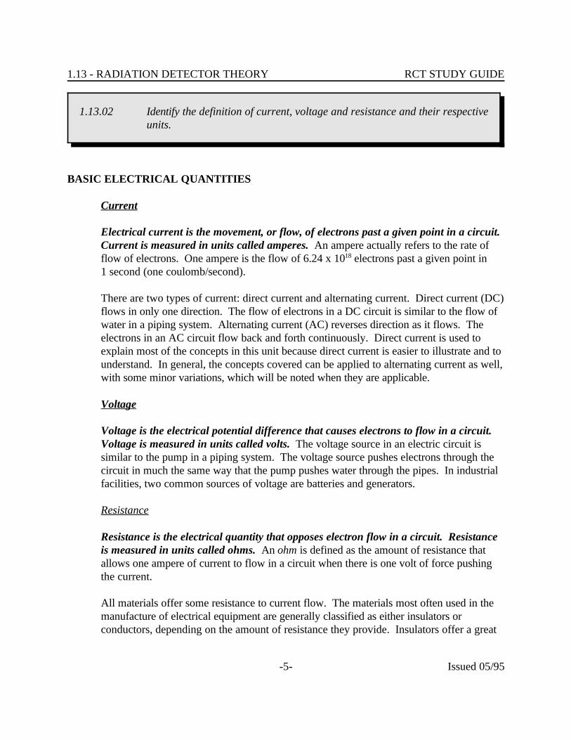
Current
Electrical current is the movement, or flow, of electrons past a given point in a circuit. Current is measured in units called amperes. An ampere actually refers to the rate offlow of electrons. One ampere is the flow of 6.24 x 10 electrons past a given point in18
1 second (one coulomb/second).
There are two types of current: direct current and alternating current. Direct current (DC)flows in only one direction. The flow of electrons in a DC circuit is similar to the flow ofwater in a piping system. Alternating current (AC) reverses direction as it flows. Theelectrons in an AC circuit flow back and forth continuously. Direct current is used toexplain most of the concepts in this unit because direct current is easier to illustrate and tounderstand. In general, the concepts covered can be applied to alternating current as well,with some minor variations, which will be noted when they are applicable.
Voltage
Voltage is the electrical potential difference that causes electrons to flow in a circuit. Voltage is measured in units called volts. The voltage source in an electric circuit issimilar to the pump in a piping system. The voltage source pushes electrons through thecircuit in much the same way that the pump pushes water through the pipes. In industrialfacilities, two common sources of voltage are batteries and generators.
Resistance
Resistance is the electrical quantity that opposes electron flow in a circuit. Resistanceis measured in units called ohms. An ohm is defined as the amount of resistance thatallows one ampere of current to flow in a circuit when there is one volt of force pushingthe current.
All materials offer some resistance to current flow. The materials most often used in themanufacture of electrical equipment are generally classified as either insulators orconductors, depending on the amount of resistance they provide. Insulators offer a great

I ER
1.13 - RADIATION DETECTOR THEORY RCT STUDY GUIDE
-6- Issued 05/95
1.13.03 Select the function of the detector and readout circuitry components in aradiation measurement system.
deal of resistance to current flow, while conductors offer very little resistance.
Ohm's Law
The relationship between current, voltage, and resistance was described by George SimonOhm in a form that is commonly referred to as Ohm's Law. Ohm's Law states that currentis equal to voltage divided by resistance. This law is often expressed using symbols foreach quantity. Using these symbols, Ohm's Law can be expressed as:
|||
where: I = current (A)|E = voltage (V)|R = resistance ( )|
The form of Ohm's Law can be changed to show two other aspects of the relationshipbetween current, voltage, and resistance. The first of these is that voltage equals currenttimes resistance, or E = IR; and the second is that resistance equals voltage divided bycurrent, or R = E/I. Ohm's Law can be used in the appropriate form to determine onequantity (current, voltage, or resistance) in an electrical circuit if the other two are known,or to predict the effect that a change in one quantity will have on another.
MEASUREMENT SYSTEMS|
All radiation measurement systems consist of a detector and some sort of a readoutcircuitry. A detector may be combined with appropriate circuitry to form an instrument,or the detector and the readout may be separate (TLD + film, for example). (See Figure|1)|
|

Detector+
Amplifier
Reading Device(Ammeter)
Battery
_
Power Source
1.13 - RADIATION DETECTOR THEORY RCT STUDY GUIDE
-7- Issued 05/95
Figure 1. Basic Radiation Measurement System
|
1.13 - RADIATION DETECTOR THEORY RCT STUDY GUIDE
-8- Issued 05/95
|||||||||||||||||
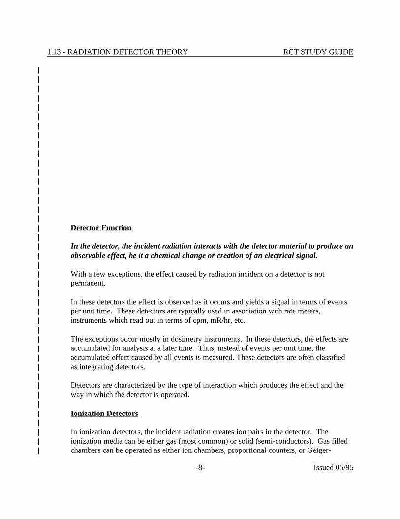
Detector Function||
In the detector, the incident radiation interacts with the detector material to produce an|observable effect, be it a chemical change or creation of an electrical signal.|
|With a few exceptions, the effect caused by radiation incident on a detector is not|permanent.|
|In these detectors the effect is observed as it occurs and yields a signal in terms of events|per unit time. These detectors are typically used in association with rate meters,|instruments which read out in terms of cpm, mR/hr, etc.|
|The exceptions occur mostly in dosimetry instruments. In these detectors, the effects are|accumulated for analysis at a later time. Thus, instead of events per unit time, the|accumulated effect caused by all events is measured. These detectors are often classified|as integrating detectors.|
|Detectors are characterized by the type of interaction which produces the effect and the|way in which the detector is operated.|
|Ionization Detectors|
|In ionization detectors, the incident radiation creates ion pairs in the detector. The|ionization media can be either gas (most common) or solid (semi-conductors). Gas filled|chambers can be operated as either ion chambers, proportional counters, or Geiger-|
1.13 - RADIATION DETECTOR THEORY RCT STUDY GUIDE
-9- Issued 05/95
1.13.03 Select the function of the detector and readout circuitry components in aradiation measurement system.
Mueller (GM) tubes. A typical solid ionization detector is a GeLi detector used in a|multichannel analyzer.|
|Excitation Detectors|
|In excitation detectors, the incident radiation excites the atoms of the detector material. |The atoms give off the excess energy in the form of visible light. Thermoluminescent|dosimeters (TLD) and scintillation detectors fall in this category.|
|Chemical Detectors|
|In chemical detectors, the incident radiation causes ionization or excitation of the detector|media thereby causing chemical changes which can be analyzed. Film badges are an|example of a chemical detector.|
|Other Detectors|
|There are a number of detectors that don't use ionization, excitation, or chemical changes. |Examples are Cerenkov detectors, Activation foils, and Biological detectors.|
||||||||
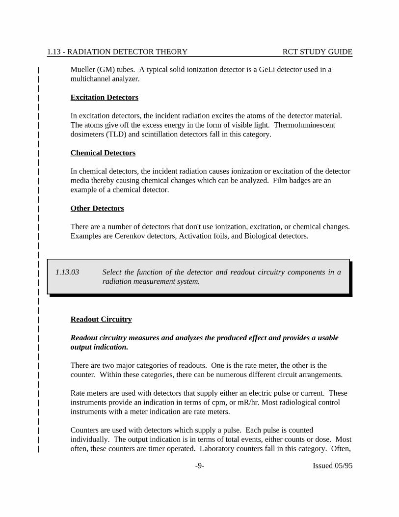
Readout Circuitry||
Readout circuitry measures and analyzes the produced effect and provides a usable|output indication.|
|There are two major categories of readouts. One is the rate meter, the other is the|counter. Within these categories, there can be numerous different circuit arrangements.|
|Rate meters are used with detectors that supply either an electric pulse or current. These|instruments provide an indication in terms of cpm, or mR/hr. Most radiological control|instruments with a meter indication are rate meters.|
|Counters are used with detectors which supply a pulse. Each pulse is counted|individually. The output indication is in terms of total events, either counts or dose. Most|often, these counters are timer operated. Laboratory counters fall in this category. Often,|
guard ring
outer insulatornegative electrode (cathode)
positive electrode (anode)
fill gas
inner insulator
1.13 - RADIATION DETECTOR THEORY RCT STUDY GUIDE
-10- Issued 05/95
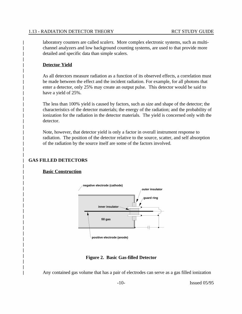
Figure 2. Basic Gas-filled Detector
laboratory counters are called scalers. More complex electronic systems, such as multi-|channel analyzers and low background counting systems, are used to that provide more|detailed and specific data than simple scalers.|
|Detector Yield|
|As all detectors measure radiation as a function of its observed effects, a correlation must|be made between the effect and the incident radiation. For example, for all photons that|enter a detector, only 25% may create an output pulse. This detector would be said to|have a yield of 25%.|
|The less than 100% yield is caused by factors, such as size and shape of the detector; the|characteristics of the detector materials; the energy of the radiation; and the probability of|ionization for the radiation in the detector materials. The yield is concerned only with the|detector.|
|Note, however, that detector yield is only a factor in overall instrument response to|radiation. The position of the detector relative to the source, scatter, and self absorption|of the radiation by the source itself are some of the factors involved.|
||
GAS FILLED DETECTORS||
Basic Construction||||||||||||||||||
Any contained gas volume that has a pair of electrodes can serve as a gas filled ionization|

1.13 - RADIATION DETECTOR THEORY RCT STUDY GUIDE
-11- Issued 05/95
detector. The detector can be almost any shape or size but is usually cylindrical. The|cylinder walls are usually used as one electrode and an axial wire mounted in the center is|used as the other electrode. Insulators support the axial electrode. It should be noted that|the size, shape, and configuration is a function of the desired detector characteristics. (See|Figure 2)|
|The gas used in the detector can be almost any gaseous mixture that will ionize, including|air. Some ionization detectors, particularly ionization chambers use only air, while other|detectors use gas mixtures that ionize more readily to obtain the desired detector|response.|
||
Basic Theory||
A gaseous mixture in a normal undisturbed state has positive and negative charges which|are balanced such that no net charge is observed. When a particle or ray interacts with the|gas atoms or molecules (and in some gases, the detector materials), energy is added to the|gas and one or more electrons may be split off of the parent atom or molecule. The most|common process results in a single negatively charged electron, leaving behind a positively|charged atom. Together the negative electron and positive atom (minus one electron) are|called an ion-pair.|
|If left undisturbed, the negative ions can be collected by a positive ion and return to a|neutral state.|
|If a voltage potential is established across the two electrodes, electric fields are set up in|the gas volume between the electrons. In most detectors, the center electrode is positively|charged, and the shell of the detector is negatively charged. If an ion pair is created|between the electrodes, the electron will be attracted to the center electrode, while the|positively charged ion will be attracted to the detector shell. When either ion reaches the|electrode, electric currents are set up. Because of mass differences, the electron reaches|the electrode first. It takes up to 1,000 times longer for the positive ion to reach the side.|
|The amount of current flow is representative of the energy and number of radiation events|that caused ionization. The readout circuitry analyzes this current and provides an|indication of the amount of radiation that has been detected.|
|
1.13 - RADIATION DETECTOR THEORY RCT STUDY GUIDE
-12- Issued 05/95
1.13.04 Identify the parameters that affect the number of ion pairs collected in a gas-filled detector.
||||||
Ion Pair Production||
For a gas filled ionization detector to be of value for radiological control purposes, the|manner in which the response varies as a function of the energy, quantity, and type of|radiation must be known. Factors such as the size and shape of the detector, the|pressure and composition of the gas, the size of the voltage potential across the|electrodes, the material of construction, the type of radiation, the quantity of radiation,|and the energy of the radiation can all affect the response of the detector. Detectors|for a special purpose are designed to incorporate the optimum characteristics necessary to|obtain the desired response.|
|Type of Radiation|
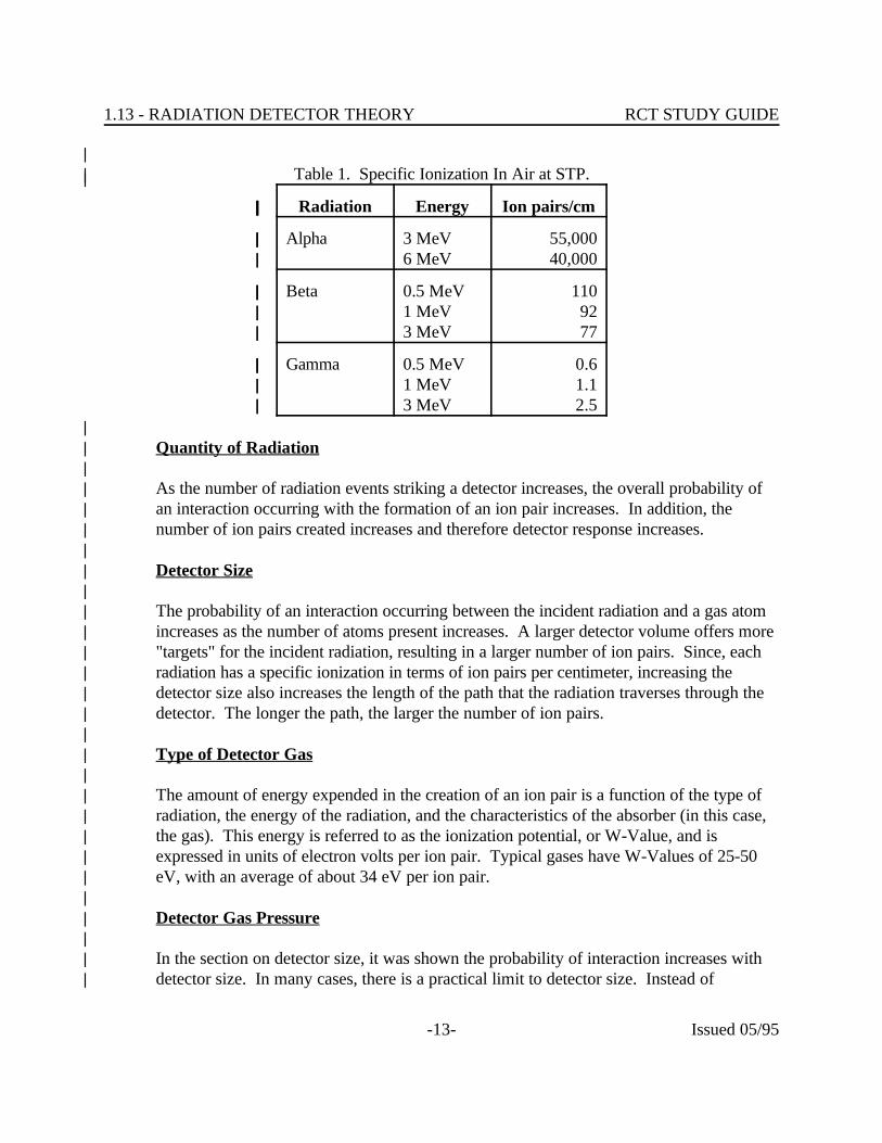
|Each type of radiation has a specific probability of interaction with the detector media. |This probability varies with the energy of the incident radiation and the characteristics of|the detector gas. The probability of interaction is expressed in terms of specific ionization|with units of ion pairs per centimeter. A radiation with a high specific ionization, such as|alpha, will produce more ion pairs in each centimeter that it travels than will a radiation|with a low specific ionization such as gamma. In Table 1, note the magnitude of the|difference between the specific ionization for the three types of radiation.|
|Energy of the Radiation|
|Review of the data in Table 1 will reveal that, generally, the probability of interaction|between the incident particle radiation and the detector gas (and therefore the production|of ions) decreases with increasing radiation energy. In photon interactions, the overall|probability of interaction increases because of the increasing contribution of the pair|production reactions. As the energy of the particle radiation decreases, the probability of|interaction increases, not only in the gas, but also in the materials of construction. Low|energy radiations may be attenuated by the walls of the detector and not reach the gas|volume. Obviously, this must be accounted for in the design of the detector.|
|
1.13 - RADIATION DETECTOR THEORY RCT STUDY GUIDE
-13- Issued 05/95
|Table 1. Specific Ionization In Air at STP.||
Radiation| Energy| Ion pairs/cm|
Alpha| 3 MeV| 55,000|6 MeV| 40,000|
Beta| 0.5 MeV| 110|1 MeV| 92|3 MeV| 77|
Gamma| 0.5 MeV| 0.6|1 MeV| 1.1|3 MeV| 2.5|
|Quantity of Radiation|
|As the number of radiation events striking a detector increases, the overall probability of|an interaction occurring with the formation of an ion pair increases. In addition, the|number of ion pairs created increases and therefore detector response increases.|
|Detector Size|
|The probability of an interaction occurring between the incident radiation and a gas atom|increases as the number of atoms present increases. A larger detector volume offers more|"targets" for the incident radiation, resulting in a larger number of ion pairs. Since, each|radiation has a specific ionization in terms of ion pairs per centimeter, increasing the|detector size also increases the length of the path that the radiation traverses through the|detector. The longer the path, the larger the number of ion pairs.|
|Type of Detector Gas|
|The amount of energy expended in the creation of an ion pair is a function of the type of|radiation, the energy of the radiation, and the characteristics of the absorber (in this case,|the gas). This energy is referred to as the ionization potential, or W-Value, and is|expressed in units of electron volts per ion pair. Typical gases have W-Values of 25-50|eV, with an average of about 34 eV per ion pair.|
|Detector Gas Pressure|
|In the section on detector size, it was shown the probability of interaction increases with|detector size. In many cases, there is a practical limit to detector size. Instead of|
1.13 - RADIATION DETECTOR THEORY RCT STUDY GUIDE
-14- Issued 05/95
increasing detector size to increase the number of "target" atoms, increasing the pressure|of the gas will accomplish the same goal. Gas under pressure has a higher density (more|atoms per cm ) than a gas not under pressure, and therefore offers more targets, a higher| 3
probability of interaction, and greater ion pair production. For example, increasing the|pressure of a typical gas to 100 psig increases the density by about 7 times.|
|Voltage Potential Across the Electrodes|
|Once the ion pair is created, it must be collected in order to produce an output pulse or|current flow from the detector. If left undisturbed, the ion pairs will recombine, and not|be collected. If a voltage potential is applied across the electrodes, a field is created in the|detectors, and the ion pairs will be accelerated towards the electrodes.|
|The stronger the field, the stronger the acceleration. As the velocity of the electron|increases, the electron may cause one or more ionizations on its own. This process is|known as secondary ionization. The secondary ion pairs are accelerated towards the|electrode and collected, resulting in a stronger pulse than would have been created by the|ions from primary ionization. |
|Effect of Voltage Potential on the Detector Process|
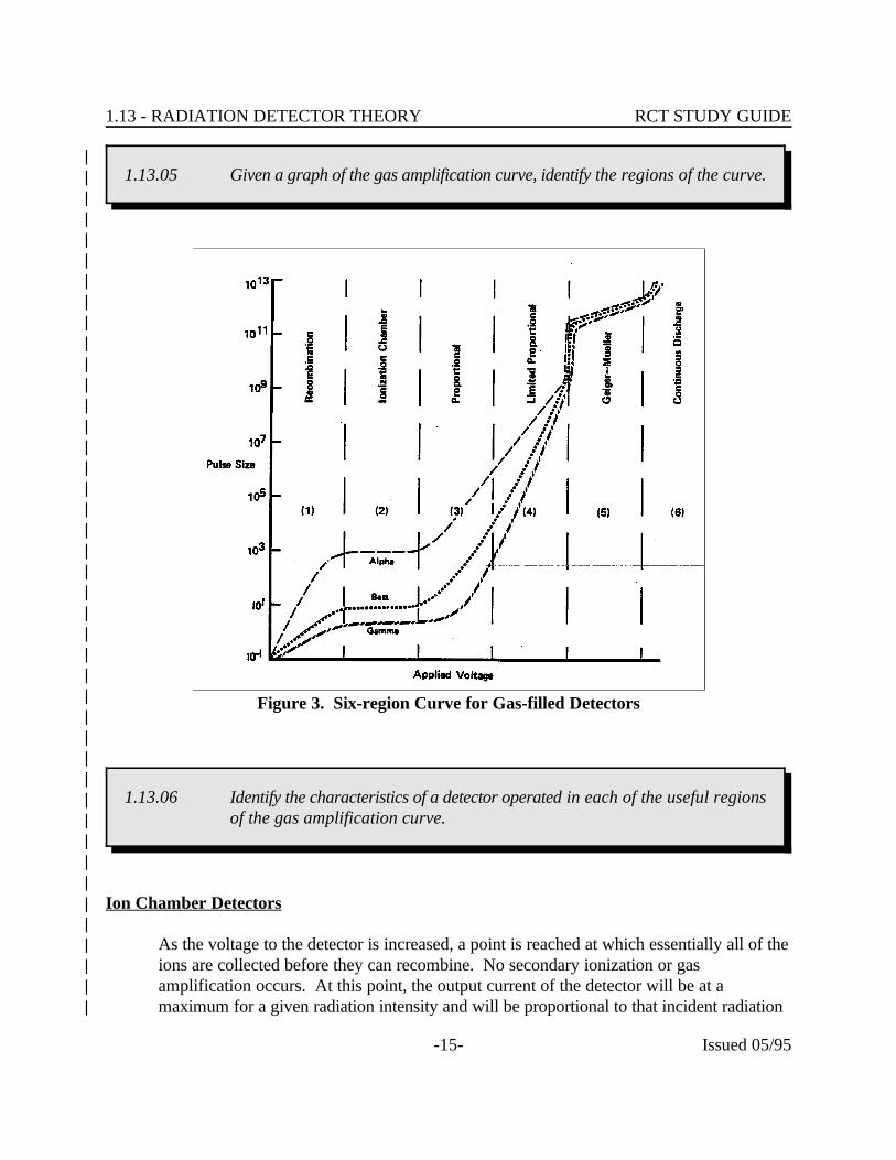
|If the applied voltage potential is varied from 0 to a high value, and the pulse size|recorded, a response curve will be observed. For the purposes of discussion, this curve is|broken into six regions. The ion chamber region, the proportional region, and the Geiger-|Mueller region are useful for detector designs used in radiological control. Other regions|are not useful. In the recombination region, the applied voltage is insufficient to collect all|of the ion pairs before some of them recombine. In the limited proportional region,|neither the output current nor the number of output pulses are proportional to the|radiation level. Calibration is impossible. In the continuous discharge region, the voltage|is sufficient to cause arcing and breakdown of the detector gas.|
|
1.13 - RADIATION DETECTOR THEORY RCT STUDY GUIDE
-15- Issued 05/95
1.13.05 Given a graph of the gas amplification curve, identify the regions of the curve.
Figure 3. Six-region Curve for Gas-filled Detectors
1.13.06 Identify the characteristics of a detector operated in each of the useful regionsof the gas amplification curve.
||||||||||||||||||||||||||||||||||||
Ion Chamber Detectors||
As the voltage to the detector is increased, a point is reached at which essentially all of the|ions are collected before they can recombine. No secondary ionization or gas|amplification occurs. At this point, the output current of the detector will be at a|maximum for a given radiation intensity and will be proportional to that incident radiation|

1.13 - RADIATION DETECTOR THEORY RCT STUDY GUIDE
-16- Issued 05/95
intensity. Also, the output current will be relatively independent of small fluctuations in|the power supply.|The output of a gas-filled detector when 100% of the primary ion pairs are collected is|called the saturation current.|
|Advantages|
|• Output current is independent of detector operating voltage. Observe the flat|
region of the curve in the ion chamber region. As a result, less regulated and|thereby less expensive and more portable power supplies can be used with ion|chamber instruments, and still offer a reasonably accurate response.|
|• Since the number of primary ion pairs is a function of the energy deposited in the|
detector by the incident radiation, the ion chamber response is directly proportional|to the dose rate.|
|• Since exposure (x) is defined in terms of ionization of air by photons, an air-filled|
ion chamber, when used for photon radiation, yields the true exposure rate.||
Disadvantages||
• Since only primary ion pairs created by each radiation event are collected, the|output currents are small. Independent current pulses large enough to measure are|not formed by each ionizing event. Instead, the total current output created by|many ionizing events is measured. Therefore, the sensitivity of a small ion|chamber is very poor because a few ionizing events per minute do not create|sufficient currents to be measured. A typical commercial portable ion chamber has|a detector which produces a current of about 2 E-14 amps per mR/hr.|
|• Another consequence of the small output current is the effect humidity can have on|
the instrument response. The electronics associated with the detector must have a|high impedance (approximately 1 E15 ohms) to measure currents this small. The|instrument incorporates insulators designed to maintain this high impedance. High|humidity conditions can cause the formation of condensation on those insulators. |(The resistance of relatively pure water is approximately 1 E7 ohms per|centimeter.) This condensation creates leakage paths which causes erroneous|instrument response.|
|• Since anything which changes the density of the gas affects the response, changes|
in barometric pressure (or altitude) and/or ambient temperature can affect|instrument response in some cases. This is particularly the case with thin-walled|chambers, vented chambers, or chambers with windows. For instance, the|
1.13 - RADIATION DETECTOR THEORY RCT STUDY GUIDE
-17- Issued 05/95
response of a typical commercial portable ion chamber instrument decreases by 2%|for each 10 degree increase in temperature, or decreases by 2.3% for each inch of|mercury decrease in barometric pressure (4.6% per psig).|
|Typical Applications|
|Portable survey instruments used for measuring dose rates are typically ion chamber|instruments. Ion chambers may also be used in several installed monitor systems such as|the Area Radiation Monitor Systems (ARMS) and the various Process Radiation Monitors|(PRMs).|
||
Proportional Detectors||
As the voltage on the detector is increased beyond the ion chamber region, the ions|created by primary ionization are accelerated by the electric field towards the electrode. |Unlike the ion chamber region, however, the primary ions gain enough energy in the|acceleration to produce secondary ionization pairs. These newly formed secondary ions|are also accelerated, causing additional ionizations. The large number of events, known as|an avalanche, creates a single, large electrical pulse.|
|In a proportional detector, the detector output is proportional to the total ionization|product in the detector. For a constant voltage, the ratio between the primary ionizations|and the total number of ions produced is a constant and is known as the Gas|Amplification Factor. The gas amplification factors for typical proportional detectors|range from a few hundred to about a million. Compare this with a Gas Amplification|Factor of only 1 for ion chamber detectors.|
|Since the gas amplification in a proportional detector is large, the output pulses are large|enough to be measured directly and individually. Since a single pulse is produced for each|incident radiation particle or photon, it is feasible to directly measure the number of|incident particles or photons which interacted with the detector. For this reason, a|proportional detector is often used as a "proportional counter" and is normally used in|instruments which read out in events per unit time, such as counts per minute. The total|current, which is a function of the number of the pulses and the pulse magnitude, could be|measured as is done with ion chamber detectors but this is only done in one type of|portable dose rate instrument.|
|As with the ion chamber detector, increasing radiation energy, or high specific ionization|radiations, will result in a larger pulse. Since we can measure the individual pulse, it is|possible to analyze both the rate of incidence and the energy or type of radiation with a|proportional counter. This allows for discrimination of different types of radiation or|
1.13 - RADIATION DETECTOR THEORY RCT STUDY GUIDE
-18- Issued 05/95
1.13.07 Identify the definition of the following terms:a. Resolving timeb. Dead timec. Recovery time
different radiation energies by varying the high voltage (which affects the gas amplification|factor).|
||||||||||
Resolving Time||
After the ion avalanche occurs, it takes a finite time for the ions to be collected and for the|pulse to be generated. Similarly, it takes a finite period of time for the pulse to decay. If|another ionizing event occurs elsewhere in the detector during this period, another|avalanche may be initiated. When the ions reach the electrodes, they are collected along|with remaining ions from the first event. The resulting pulse may not be distinguishable as|two pulses by the associated electronics. The resulting reading will underestimate the|actual radiation field. The period of time between events, such that two distinguishable|pulses result, is known as resolving time. Resolving time is the total amount of time|from a measurable detector response before another pulse can be measured. In the|proportional region, the resolving time is short, usually in the range of 0.5 to 1 nano|seconds. This resolving time does not lead to problems at low count rates, but can result|in a considerable error at high count rates. It should be noted that usually the associated|electronics will have a resolving time longer than that of the detector.|
|Counter Construction|
|Proportional counters can be constructed using self-contained gas volumes or with|continuously cleaning gas volumes. The latter is usually called a gas flow proportional|counter. The detectors can also be constructed with the sample holder integral to the|detector, eliminating the need for a detector window.|
|• Cylindrical Counter - This configuration is typical of the proportional counters|
used in portable survey instruments. The fill gas is commonly a hydrocarbon gas|such as P-10 (methane and argon), but other gases have been employed. For|example, BF gas (boron trifluoride) is often used in detectors designed to count| 3
neutrons.||

Gas in Gas out
Detectorwindow
Sample slideassembly
Sample holder
Sample
Anode
1.13 - RADIATION DETECTOR THEORY RCT STUDY GUIDE
-19- Issued 05/95
Figure 4. Basic 2 Proportional Detector w/ Window
• Window 2 Gas Flow Hemispherical Counter - In this detector the gas volume is|replenished continuously, ensuring a constant supply of target atoms. (See Figure|4) P-10 is the most commonly used counting gas. The geometry of the detector is|such that, theoretically, almost 50% of the radiation's emitted from the source|would be available for detection. (The terms 2 and 4 refer to the number of|steradians around a point source in space. There are 2 steradians in a hemisphere,|4 in a sphere.) In reality, the actual percentage may be somewhat higher due to|backscatter.|
||||||||||||||||||||||||
• Windowless 2 Gas Flow Hemispherical Counter - This counter is similar to the|2 gas flow counter with the window. In fact, many of the gas flow proportional|counters commercially available can be converted between window and|windowless operation by a simple modification. In this counter, the source is|effectively within the detector. This allows for the counting of low energy or low|penetrating power radiation's which would have been stopped by the detector|window.|
|• 4 Gas Flow Spherical Counter - With this counter, the source material to be|
analyzed is deposited on an extremely thin membrane. This membrane is then|
1.13 - RADIATION DETECTOR THEORY RCT STUDY GUIDE
-20- Issued 05/95
positioned between the chamber halves, and the gas purge started. This detector|approaches the ideal 4 geometry. Because of the relative difficulty of use, this|counter finds little application at power stations.|
|• Gas Flow, Flat - This is a commercially available alpha counter which is used in a|
portable alpha survey instrument. The counting gas is propane.||
Proportional Counter Advantages||
• A proportional counter can be used to discriminate between the different types of|radiation.|
|• A proportional counter output signal is larger and therefore a single ionizing event|
can be recorded (good sensitivity).||
• When measuring current output, a proportional detector is useful for dose rates|since the output signal is proportional to the energy deposited by ionization and|therefore proportional to the dose rate.|
|Proportional Counter Disadvantages|
|• A proportional counter is sensitive to high voltage changes because of the effect|
on the gas amplification factor. As a result, more highly regulated power supplies|are necessary for proportional counters.|
|Typical Applications|
|Proportional counters find wide application in power stations. Gas flow proportional|counters are commonly used for alpha/or beta counting on laboratory samples. |Proportional counters are commonly used for neutron monitoring, from portable neutron|survey instruments to nuclear reactor neutron flux instruments.|
|Geiger-Mueller Detectors|
|As the voltage on the detector is increased beyond the proportional region, the detector|enters the limited proportional region. As mentioned before, this region is unusable for|radiological control purposes. In this region the small individual avalanches which occur|within the tube start to interfere with each other. This interference is unpredictable and|reduces the overall output signal.|
|As the voltage is increased further, the secondary ions are also accelerated to very high|velocities and gain sufficient energy to cause ionization themselves. These tertiary|
1.13 - RADIATION DETECTOR THEORY RCT STUDY GUIDE
-21- Issued 05/95
ionizations spread rapidly throughout the tube causing an avalanche. The avalanche,|caused by a single ionization, results in a single very large pulse. The avalanche continues|until the fields created by the produced ions interfere with the field created by the high|voltage potential across the detector. When this occurs, the amount of acceleration|decreases preventing further secondary ionization and halting the avalanche.|
|The output pulse size is a function of the gas amplification which occurs. In a GM tube,|the gas amplification can range upwards from about 1 E8. Since the number of ions|eventually produced and collected have no relation to the initial incident ionizing event,|the pulse size is independent of radiation energy or specific ionization (a 0.1 MeV gamma|creates the same size pulse as a 0.5 MeV gamma). For this reason, GM tubes cannot|discriminate against different radiation types or radiation energies.|
|Any radiation event with sufficient energy to create the first ion pair can create a large|pulse. For this reason, the GM detector is more sensitive than the ion chamber or|proportional counter.|
|A GM detector can also be avalanched by the small amount of energy released by a|positive ion when it is neutralized at the cathode. To prevent this undesirable occurrence,|a quenching gas is added to the counting gas. Thus, instead of causing ionization, this|excess energy is expended in dissociating the quenching gas molecules.|
|Dead Time and Recovery Time|
|In the discussion on proportional counters, we found that if the ionizing events occurred at|too fast a rate, the output pulses created by these events may overlap, and as such cannot|be counted as individual pulses. Although the resulting pulse is larger, the two pulses|which caused it are approximately the same size (gas amplification remains relatively|constant). The time between incident events such that individually distinguishable,|measurable, pulses result is known as the resolving time. This time is about 100-200 sec.|
|In GM detectors, resolving time has greater impact on detector response. Resolving time|is the time from the initial measured pulse until another pulse can be measured by the|electronics. Resolving time is controlled by the electronics.|
|Dead time is time from the initial pulse until another pulse can be produced by the|detector.|
|Recovery time is the time from the initial full size pulse to the next full size pulse|produced by the detector. The recovery time includes a smaller interval of time known as|the dead time. During the dead time, the detector can not respond to another ionizing|

1.13 - RADIATION DETECTOR THEORY RCT STUDY GUIDE
-22- Issued 05/95
Figure 2. Dead Time of a GM Detector
event. The dead time occurs because of the effect that the large number of positive ions|have on the voltage potential across the detector. In the recovery time, the detector can|respond, but because of a reduced gas amplification factor, the output pulses are too small|to measure. In most common day-to-day use, the resolving time is usually called the dead|time since for all practical purposes, the detector is "dead" until a pulse large enough to|trigger the electronics is created.|
|||||||||||||||||
The following sequence of events should help to explain the processes involved in|GM detection.|
|• At time zero, the voltage potential across the detector is maximum. An|
incident radiation causes ionization, resulting in an ion pair.||
• These ion pairs are accelerated towards the center electrode, thereby gaining|energy.|
|• The primary ion pairs cause secondary ionization. The ion pairs created by|
the secondary ionization begin to accelerate towards the center electrode,|thereby gaining energy. Since the potential is greatest near the center|electrode, the bulk of the ionization occurs near the center electrode.|
|• The secondary ion pairs cause additional ionization and ion pairs. These ion|
pairs are accelerated and begin to cause ionization of their own. This process|continues and an avalanche occurs.|
|• The negative ions (electrons) are collected by the center electrode and form a|
1.13 - RADIATION DETECTOR THEORY RCT STUDY GUIDE
-23- Issued 05/95
pulse. The positive ions form a cloud surrounding the center electrode. This|ion cloud reduces the voltage potential across the detector. With a reduced|voltage potential the gas amplification factor decreases such that secondary|ionization stops, thereby halting the avalanche.|
|The events described above occur very rapidly, in the range of a fraction of|microsecond. During this period the positive ion cloud is relatively stationary. The|positive ion cloud is the cause of both the dead time and recovery time. Continuing:|
|• The positive ion cloud starts to drift towards the shell of the detector.|
|• As the cloud drifts, the voltage potential starts to increase.|
|• After about a microsecond (typically) the voltage potential is high enough to|
collect the electrons from another ionization should they occur. This is the|end of the dead time. If another event does occur, the pulse will be very|small and probably not measurable as the detector voltage is in the ion|chamber region.|
|• As the ion cloud continues to drift, the voltage potential continues to increase|
and gas amplification starts to occur. The detector is now in the proportional|region. An event which occurs now will result in a large pulse. Whether or|not this pulse is measured is a function of the input sensitivity of the|electronic package.|
|• Eventually the gas amplification factor will increase to the point where an|
avalanche can occur when the positive ions reach the detector shell and are|neutralized. At this point the detector has recovered and is ready for another|radiation event. This time is about 100-300 sec in typical detectors.|
|• During neutralization, the positive ions may release photons which in|
themselves could cause an avalanche if no quenching gas was present. |Instead, the photons react with the molecules of the quenching gas, thereby|dissipating their energy.|
|The effect of the long resolving time in a GM detector is to reduce the ability of the|detector to measure high dose rates accurately. For example, with a 200 sec|resolving time, a count rate of 10,000 cpm will be measured as 9,700 cpm, an error|of 3%. At 100,000 cpm, the measured count rate will be 75,000, an error of 25%.|
|There is another effect in GM detectors that is related to resolving time. If the|incident radiation events occur at an extremely high rate, a string of small pulses|

1.13 - RADIATION DETECTOR THEORY RCT STUDY GUIDE
-24- Issued 05/95
will occur. These pulses prevent the GM detector from completely recovering. |Since a full size pulse does not occur, the electronics will not indicate that any|radiation is present.|
|GM Detector Construction|
|Although there is no technical reason why GM detectors cannot be operated as gas|flow detectors, this is not commonly done. Almost all GM detectors which are|encountered in radiological control work are cylindrical in construction.|
|Advantages of GM Detectors|
|• GM detectors are relatively independent of the pressure and temperature|
effects which affect ion chamber detectors. This is because of the magnitude|of the output pulse.|
|• GM detectors require less highly regulated power supplies. This is because|
the pulse repetition rate is measured and not the pulse height.||
• GM detectors are generally more sensitive to low energy and low intensity|radiations than are proportional or ion chamber detectors.|
|(There are exceptions.)|
|• GM detectors can be used with simpler electronics packages. The input|
sensitivity of a typical GM survey instrument is 300-800 millivolt, while the|input sensitivity of a typical proportional survey instrument is 2 millivolt.|
|Disadvantages of GM Detectors|
|• GM detector response is not related to the energy deposited; therefore GM|
detectors can not be used to directly measure true dose, as can be done with|an ion chamber instrument.|
|• GM detectors have a typically large recovery time. This limits their use in|
extremely high radiation fields. Dead time in a GM detector can be reduced|by reducing the physical size of the detector. However, the smaller the|detector, the lower the sensitivity. For this reason, wide range GM survey|instruments, such as the Teletector or the E520, commonly have two GM|detectors - one for the low ranges, one for the high ranges.|
|• GM detectors can not discriminate against different types of radiation (, , ),|
1.13 - RADIATION DETECTOR THEORY RCT STUDY GUIDE
-25- Issued 05/95
1.13.08 Identify the methods employed with gas-filled detectors to discriminatebetween various types of radiation and various radiation energies.
nor against various radiation energies. This is because the size of the GM|avalanche is independent of the primary ionization which created it.|
||
Typical Applications||
GM detectors are widely used in portable survey instruments at nuclear power|facilities due to their ruggedness and the simplicity of the associated electronics. GM|detectors are also used for personal monitoring for contamination (friskers), for|process monitoring, and for area radiation monitoring. In addition, GM detectors|are often used for laboratory counting when just a gross count is desired.|
|Comparison of the Various Radiation Detectors|
|When comparing the various detectors, one should keep in mind that exceptions are|possible, (e.g. a large, pressurized ion chamber may be more sensitive than a small|GM detector, even though, as a class, GM detectors are more sensitive than ion|chambers.)|
||||||||
DISCRIMINATION||
In the sections above, discrimination of radiation types and radiation energies was|introduced. Discrimination plays an important role in radiation measurement. In|nuclear power stations, "pure" radiation fields seldom exist. There is usually a|combination of gamma, neutron, beta, and sometimes alpha. These radiation types|also exist at various radiation energies.|
|In the complex radiation fields such as this, it becomes difficult to measure one|radiation in the presence of others - a detector that responds to alpha and beta|radiation will often also respond to gamma. Discrimination makes it possible to|separate (to some extent) the different radiation types or radiation energies.|
|Physical Discrimination |
|Shielding|

1.13 - RADIATION DETECTOR THEORY RCT STUDY GUIDE
-26- Issued 05/95
Shielding is the most common method of discriminating against certain radiation|types or energies in radiation measurements. A thin metal window will stop the|majority of alpha particles. A thicker metal window will stop beta particles. |Unfortunately, this process only works by discriminating against lower energies or|radiations with low penetrating power. Gamma radiations cannot be shielded|against without affecting response to beta or alpha.|
|Shielding is sometimes used on GM detectors to obtain a smoother energy response|curve.|
|Detector Gas Fill|
|Each type of radiation has a specific ionization factor in a particular gas. In|addition, each different detector gas has a different response to various radiation|energies. By employing the most advantageous gas, a detector can be constructed|that will have a higher yield for a specific radiation type or radiation energy than it|will for other radiation types or energies.|
|A specific example of this is the use of BF gas in proportional detectors to measure| 3
neutrons. In these detectors, the incident neutron fissions boron into lithium and an|alpha particle. This alpha particle has a much higher specific ionization than does a|gamma photon. The pulses created by neutrons are much larger than those created|by gamma. The electronics sort out the pulses by pulse height.|
|Electronic Discrimination|
|In the previous sections, we found that in the ionization chamber and proportional|regions, the output pulse height was a function of the specific ionization of the|radiation, and the incident radiation energy. Because of the small pulse size, ion|chambers are usually not used for discrimination. Proportional counters are often|used to discriminate between radiation's and sometimes between radiation energies. |The proportional gas flow counter used in counting rooms to measure alpha and/or|beta sources is an example of such an application.|
|Analyzing pulse heights is the primary method of electronic discrimination. Almost|all electronic packages used with radiation detectors have an adjustable input|sensitivity (often called discriminator level). By adjusting the input sensitivity to the|desired value, we can chose the minimum pulse height which will be measured. All|pulses smaller than this preselected pulse height will be rejected and not counted. |For example, if we have set the input sensitivity to measure only the large alpha|pulses, the smaller beta or gamma pulses will be ignored. The readout, then, will|indicate only alpha radiation.|
1.13 - RADIATION DETECTOR THEORY RCT STUDY GUIDE
-27- Issued 05/95
1.13.09 Identify how a scintillation detector and associated components operate todetect and measure radiation.
Some electronics packages also have an adjustable upper discriminator. In these|circuits, pulses that are too large will not be counted. The resulting band between|the lower and upper discriminators is called a window. Only pulses which fall|within the window will be counted. By changing the upper and lower|discriminators, an unknown radiation field or sample can be analyzed to determine|which type of radiation or which energies of radiation exist in the field or in the|sample. This process is called pulse height analysis.|
|In proportional counters, it is common practice to leave the discriminators on one|setting and to vary the high voltage supply instead. As you remember, increasing|the high voltage, increases the gas amplification factor, which in turn increases pulse|height, and vice versa. Thus, alpha radiation would be measured at one voltage,|alpha and beta at a higher voltage (subtracting the alpha count from the alpha +|beta count yields the beta count).|
||||||||
SCINTILLATION DETECTORS||
Scintillation detectors measure radiation by analyzing the effects of the excitation of|the detector material by the incident radiation. Scintillation is the process by which|a material emits light when excited. In a scintillation detector, this emitted light is|collected and measured to provide an indication of the amount of incident radiation. |Numerous materials scintillate - liquids, solids, and gases. A common example is a|television picture tube. The coating on the screen is excited by the electron beam,|and emits light. A material which scintillates is commonly called a phosphor or a|fluor. The scintillations are commonly detected by a photomultiplier tube (PMT).|
|
1.13 - RADIATION DETECTOR THEORY RCT STUDY GUIDE
-28- Issued 05/95
Scintillation Detector Components||
Each scintillation detector is comprised of two major components, the phosphor or|fluor, and the photomultiplier tube. Various different phosphors and|photomultiplier tubes are available, and numerous combinations of these are|possible. The combination chosen is selected to achieve the desired response to|radiation and other requirements of a particular application.|
|Phosphors and Fluors|
|There are four classes of phosphors of interest in field applications of scintillation: |organic crystals, organic liquids, inorganic crystals, and inorganic powders. The|theory of operation, use, and response of these phosphors varies. Each will be|discussed individually.|
|Organic Crystals|
|Organic crystal phosphors are normally aromatic hydrocarbons which contain|benzene rings. The most common organic crystal is anthracene. Anthracene offers a|high response to beta radiation and is commonly used in beta phosphors. The decay|time (which is a major part of scintillation resolving time) is on the order of 3 E-8|seconds (0.03 sec).|
|Gamma photons do not interact often or create a large pulse from interactions in the|low density anthracene (1.25 g/cm ). Therefore, it is easy to detect only beta in the| 3
presence of a mixed beta and gamma field.||
In organic crystals, the incident radiation raises the molecules of the phosphor to a|higher energy state. Upon decay back to the ground state, these molecules emit|light.|
|Organic Liquids|
|Organic liquid phosphors, usually called fluors, are comprised of organic material|suspended in an organic solvent. The organic material, usually called the solute, is|the scintillator. The solvent absorbs the radiation and transfers energy to the solute. |The mixture of solute and solvent is commonly called a "cocktail." Numerous|mixtures are available. These mixtures have a typical decay time of 2 - 8 E-9|seconds (0.002 - 0.008 sec) and a density of 0.86 g/cm .| 3
|The organic liquid fluor operates as follows: The incident radiation interacts with|the molecules of the solvent, exciting the molecules. By a process not well|

1.13 - RADIATION DETECTOR THEORY RCT STUDY GUIDE
-29- Issued 05/95
understood, the excited molecules transfer their energy to the molecules of the|solute. The molecules of the solute return to the ground state by emission of a light|photon.|
|Inorganic Crystals|
|Inorganic crystals are comprised of inorganic salts, normally halides, which contain|small quantities of impurities, called activators. The most commonly used inorganic|crystal scintillator is sodium iodide, activated with thallium - commonly subscripted|NaI(Tl). NaI(Tl) crystals have a high density - 3.7 g/cm , which allows for improved| 3
gamma photon response. The decay time is about 3 E-7 seconds (0.3 sec). NaI(Tl)|has a high response to beta particles; however, the need to hermetically seal a|NaI(Tl) crystal to prevent deterioration, limits the actual beta response.|
|Inorganic crystals operate as follows:|
|• An incident photon interacts with the crystal atoms (NaI) exciting the atom|
and raising valence band electrons to the conductance band, leaving a "hole"|in the valence band.|
|• Some of these electrons and holes recombine to form an "exciton." The|
excitons, free holes, and free electrons drift through the crystal.||
• The impurity centers (T1) capture the excitons, free holes, and free electrons. |This capture raises the impurity center to an excited state.|
|• The impurity center will decay back to the ground state, and in doing so,|
emits a light photon, which is proportional to the energy of the incident|radiation.|
|Inorganic Powders|
|Zinc Sulfide activated with Silver (ZnS(Ag)) is an inorganic powder which is|commonly used as a phosphor in alpha scintillators. ZnS(Ag) scintillators have a|high density, 4.1 g/cm , and a relatively high response to beta and alpha radiation's. | 3
The response of this scintillator to beta and gamma is minimized by the use of|ZnS(Ag) as a thin film which is within the alpha interaction range, but too thin for|that of beta or gamma. ZnS(Ag) emits two light photons one at 4-10 E-8 seconds|(0.04 - 0.1 sec), and another at 4-10 E-5 seconds (40 - 100 sec).|
|Inorganic powders operate with a mechanism similar to that of inorganic crystals.|
|
1.13 - RADIATION DETECTOR THEORY RCT STUDY GUIDE
-30- Issued 05/95
Photomultiplier Tubes||
The purpose of the photomultiplier tube is to detect the scintillations and to provide|an output signal proportional to the amount of scintillations. In doing this,|photomultiplier tubes can provide amplifications of 1 E6 and higher.|
|Construction|
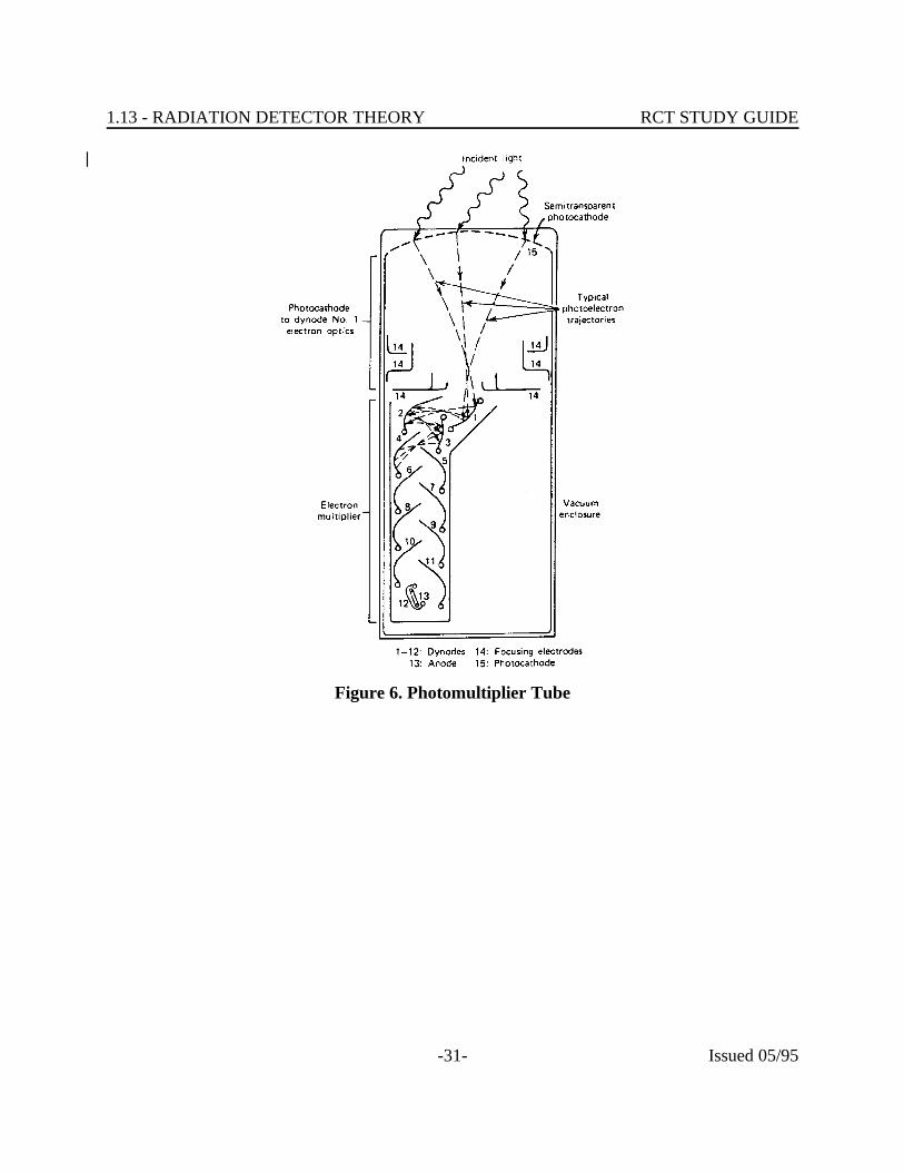
|Construction details vary from design to design, however, all photomultipliers have|typical components. These common components are: the photocathode, the dynode|assembly, an anode, voltage divider network, and shell. These components perform|as follows: (See Figure 6)|
|• Photocathode - made of an antimony - cesium composite. The purpose of the|
photocathode is to convert the light photons to electrons (called|photoelectrons).|
|• Dynode Assembly - A series of electrodes used to amplify the signal. Each|
successive dynode has a higher voltage potential. The voltage gradient along|the tube accelerates the electrons towards the anode. This works as follows:|the photoelectron strikes the first dynode freeing one or more electrons. |These electrons are drawn towards the second dynode. At the second dynode|each electron frees one or more additional electrons. This process continues|until the electron cascade reaches the anode. Through this process, the initial|photoelectron is amplified, up to 10 times and higher. For an amplification| 6
of 10 an average of 4 electrons is freed by each incident electron reacting| 6
with each dynode (10 dynodes - 4 10 ).| 10 6
|• Anode - The anode collects the electrons and generates an output pulse.|
|• Voltage Divider Network - Splits the high voltage supply into the various|
potentials required by the dynodes.||
• Shell - Supports the other components and seals the tube from stray light and|stray electric/magnetic fields.|
|
1.13 - RADIATION DETECTOR THEORY RCT STUDY GUIDE
-31- Issued 05/95
Figure 6. Photomultiplier Tube
|
1.13 - RADIATION DETECTOR THEORY RCT STUDY GUIDE
-32- Issued 05/95
|||||||||||||||||||||||||||||
Output||
The photomultiplier tube provides an output pulse which is proportional to the|incident photons. The size of the pulse is a function of the energy of the light|photon, and of the electron multiplication. Varying the HV to the photomultiplier|varies the pulse height.|
|It is possible for stray electrons to be amplified by the dynode, creating an output|pulse while no photon entered the tube. Those electrons can be spontaneously|emitted from the photocathode or by the dynodes themselves. This output signal is|commonly called dark current. Dark current increases with photomultiplier tube|temperature, hence, temperature changes may cause the detector to "drift."|
|

1.13 - RADIATION DETECTOR THEORY RCT STUDY GUIDE
-33- Issued 05/95
Applications of Scintillation Detectors||
Inorganic Crystals - NaI(Tl)||
NaI(Tl) scintillation detectors are commonly used in applications where high gamma|sensitivity and a high energy resolution is desired.|
|• The solid nature of the crystal "offers" more targets to a photon than does a|
GM detector. For this reason, gamma scintillators typically have higher|yields than equivalently sized GM detectors.|
|• The light output of the crystal is a function of the incident photon energy. |
The output signal of the photomultiplier tube is a function of the light input,|and therefore is proportional to the energy of the incident radiation. This|characteristic allows scintillators to be used to perform pulse height analysis|for radiation energy. The NaI(Tl) scintillator has a higher energy resolution|than a proportional counter, allowing for more accurate energy|determinations. Resolution is the characteristic of a detector to be able to|differentiate between two close radiation energies. The higher the resolution,|the closer the radiation energies can be to each other and still be|differentiated. It should be noted that recent advances with semiconductor|detectors have provided detectors with even better resolution than NaI(Tl).|
|Liquid Scintillation Detectors|
|Crystal scintillation detectors such as NaI(Tl) have two limiting characteristics. The|crystals are 2 in nature; this fact lowers the possible efficiency of the detector. The|crystals need to be hermetically sealed. The materials used for sealing attenuate|lower energy radiation and both beta and alpha radiations.|
|Liquid scintillation units have been developed to remedy these situations for those|applications where it is desired to measure radiation of low energy or low|penetrating ability.|
|In liquid scintillation units, the fluor is mixed with the material to be analyzed|(usually a liquid). This vessel containing the fluor-sample mixture is then placed in|a photomultiplier tube array. (One or more PMTs may be used.)|
|In this manner, it is possible to analyze low energy beta emitters such as tritium|(0.019 MeV) and/or carbon-14 (.16 MeV), and to approximate 4 geometry.|
|

1.13 - RADIATION DETECTOR THEORY RCT STUDY GUIDE
-34- Issued 05/95
1.13.10 Identify how neutron detectors detect neutrons and provide an electricalsignal.
|Advantages of Scintillation Detectors|
|• Ability to discriminate between alpha, beta, gamma radiations and between|
different radiation energies with a moderate resolution.||
• (NaI(Tl)): High gamma sensitivity.||
• (Liquid): Extremely low energy response.||
• (ZnS(Ag): Most advantageous alpha detector.||
Disadvantages||
• (NaI(Tl)): No beta or alpha response, poor low energy gamma response.||
• (Liquid): Relatively cumbersome. Solution is one time use only.||
• Requires a regulated power supply for pulse height analysis.||
• (NaI(Tl) and ZnS(Ag)): Detector is not a solid state device, needs to be|handled with care.|
||||||||
NEUTRON DETECTION||
Because neutrons do not interact with material to form ions, they must be detected|indirectly. Several techniques are used.|
|Slow Neutron Detection|
|Boron Activation|
|When slow neutrons strike an atom of Boron-10, an alpha particle is emitted. This|alpha particle, in turn, produces ionizations which can be measured. A detector is|lined with Boron-10 or filled with Boron trifluoride, BF , gas. These detectors are| 3

1.13 - RADIATION DETECTOR THEORY RCT STUDY GUIDE
-35- Issued 05/95
usually operated in the ion chamber region or the proportional region. Boron|activation is the most commonly used method for slow neutron detection.|
|Photographic film can be made sensitive to slow neutrons by adding boron.|
|Fission Chambers|
|A slow neutron will cause an atom of U-235 to fission, with the two fission fragments|produced having a high kinetic energy and causing ionization to the material they|pass through. Thus, by coating one of the electrodes of an ionization chamber with|a thin layer of uranium enriched in U-235, a detector sensitive to slow neutrons is|formed.|
|Scintillation|
|Scintillation detectors can be designed to detect slow neutrons by incorporating|boron or lithium in the scintillation crystal. The neutrons interact with the boron or|lithium atoms to produce an alpha particle, which then produces ionization and|scintillation.|
|Slow Neutron Thermoluminescence|
|Thermoluminescent dosimeters can be designed to detect slow neutrons by|incorporating lithium-6 in the crystal.|
|Activation Foils|
|Various materials have the ability to absorb neutrons of a specific energy and|become radioactive through the radiative capture process. By measuring the|radioactivity of thin foils such as gold, silver or indium, we can determine the|amount of neutrons to which the foils were exposed. Commercially available|criticality accident dosimeters often utilize this method.|
|Fast Neutron Detection|
|Proton Recoil (Ion Chamber/Proportional)|
|When fast neutrons undergo elastic scatterings with hydrogen atoms, they|frequently strike the hydrogen atom with enough force to knock the proton nucleus|away from the orbiting electron. This energetic proton then produces ionization|which can be measured. Most devices for measuring fast neutrons use an ionization|detector operated in either the ion chamber or proportional region.|

1.13 - RADIATION DETECTOR THEORY RCT STUDY GUIDE
-36- Issued 05/95
|
1.13 - RADIATION DETECTOR THEORY RCT STUDY GUIDE
-37- Issued 05/95
|Thermalization (Slowing Down Fast Neutrons)|
|There are several methods for detecting slow neutrons, and few methods for|detecting fast neutrons. Therefore, one technique for measuring fast neutrons is to|convert them to slow neutrons, and then measure the slow neutrons. In this|technique, a sheet of cadmium is placed on the outside of the detector to absorb any|slow neutrons which might be present. A thickness of paraffin, or another good|moderator, is placed under the cadmium to convert the fast neutrons to slow ones. |One of the slow neutron detectors is positioned inside the paraffin to measure the|slow neutrons, thereby measuring the original fast neutrons.|
|Commercial Application - Dose Rate Instrument|
|Neutrons are not detected with any degree of efficiency by common ion chambers,|GM tubes, or proportional counters. Any detection of neutrons by these detectors is|due to absorption of neutrons by detector materials or hydrogen recoil. The|detection efficiency can be increased by the utilization of materials with high|neutron absorption cross section. The basic material typically used is Boron. Boron|can be used either as a coating or as a gas, in the form of BF . Boron, when it| 3
absorbs a neutron, emits an alpha particle according to the following reaction:||
B + n Li +| 10 1 7
|The alpha particle causes ionization and gas amplification provides a usable|electrical signal. This reaction occurs only for thermal neutrons. Fast and|intermediate neutrons must be converted to thermal neutrons before they can be|detected using Boron. Typical thermalizing materials are paraffin and polyethylene.|
|Because of the energy dependence of neutron interaction, and the wide range of|neutron energies, the response curve of the detector is not linear. Attempts are|made in design to have the detector response curve approximate the quality factor|versus energy curve by placing a sphere or cylinder of polyethylene around the|detector. (Polyethylene closely approximates human tissue in composition.) Other|techniques such as controlled loading with cadmium, boron, or radially drilled holes|are used to make the detector response more equivalent to dose rate.|
|The NBS released a table of the average flux to obtain 100 mrem/hr for various|neutron energies. (See Table 2) The goal of shield and detector design is to|approximate this relationship.|
|

ValenceBand
ForbiddenBand
ConductionBand
Conductor(narrow gap)
1.13 - RADIATION DETECTOR THEORY RCT STUDY GUIDE
-38- Issued 05/95
1.13.11 Identify the principles of detection, advantages and disadvantages of a GeLidetector and an HPGe detector.
Figure 7. Conductor
|Table 2. Neutron Flux/Dose Relationship||
Average Flux (n/cm -sec)| 2
Neutron Energy in MeV| To obtain 1 mrem/hr|
0.0001| 268| 0.02| 200|0.1| 110|1.0| 32|2.5| 8.0|5.0| 7.2|7.5| 6.8|
10-30| 4.0||||
SEMICONDUCTOR DETECTORS||||||||
Principles of Semiconductor Detectors|||
In a crystal, the atoms are packed so tightly together that the|energy states of individual atoms are modified. This modification|splits the states into a number of closely spaced energy levels or|bands. The top most band (called the conduction band) has|unfilled energy levels. In a conducting solid, the group of "filled|bands" is in direct contact with the group of "unfilled bands," so|electrons are easily moved into the conduction band.|
||||

ValenceBand
ForbiddenBand
ConductionBand
(wide gap)Insulator
ValenceBand
ForbiddenBand
ConductionBand
(smaller gap)Semiconductor
e-
hole
1.13 - RADIATION DETECTOR THEORY RCT STUDY GUIDE
-39- Issued 05/95
Figure 8. Insulator
Figure 9. Semiconductor
Figure 10. Electron Hole
||
In a good insulator, there is a large enough gap between the|group of filled bands and the group of unfilled bands so that a|large amount of energy is required to move an electron to the|conduction band.|
||||||
A semiconductor has a smaller gap between the two groups of|bands so that under certain conditions, electrons can be moved to|the conduction band. (For example, heating the material will|move at least some electrons to the conduction band.)|
|||||||
When an electron is moved to a higher band, that is, from|valence to conduction, a vacancy occurs in the band which it left. |This vacancy is called a hole.|
|||||
If a strong electric field is applied to the crystal, the electron in the conduction band|moves in accordance with the applied field. Similarly, in the group of filled bands,|an electron from a lower energy band moves up to fill the hole (vacancy) in the|valence band. The hole it leaves behind is filled by an electron from yet a lower|energy band. This process continues, so the net effect is that the hole appears to|move down through the energy bands in the filled group. Thus, the electron moves|in one direction in the unfilled group of bands, while the hole moves in the opposite|direction in the filled group of bands. This can be likened to a line of cars awaiting|a toll booth, the toll booth being the forbidden band. As a car leaves the "filled|valence band" for the unfilled conductance band, a hole is formed. The next car in|line fills this hole, and creates a hole, and so on. Consequently, the hole appears to|
1.13 - RADIATION DETECTOR THEORY RCT STUDY GUIDE
-40- Issued 05/95
move back through the line of cars.||
Any impurities in the crystalline structure can affect the conducting ability of the|crystalline solid. There are always some impurities in a semiconductor, no matter|how "pure" it is. However, in the fabrication of semiconductors, impurities are|intentionally added under controlled conditions. If the impurity added has an|excess of outer electrons, it is known as a donor impurity, because the "extra"|electron can easily be raided or donated to the conduction band. In effect the|presence of this donor impurity decreases the "gap" between the group of filled|bands and the group of unfilled bands. Since conduction occurs by the movement of|a negative charge, the substance is known as an n-type material. Similarly, if the|impurity does not contain enough outer electrons, a vacancy or hole exists. This|hole can easily accept electrons from other energy levels in the group of filled bands,|and is called an acceptor substance. Although electrons move to fill holes, as|described above, the appearance is that the holes move in the opposite direction. |Since this impurity gives the appearance of positive holes moving, it is known as a p-|type material.|
|Since any crystalline material has some impurities in it, a given semiconductor will|be an n-type or a p-type depending on which concentration of impurity is higher. If|the number of n-type impurities is exactly equal to the number of p-type impurities,|the crystalline material is referred to as an "intrinsic semiconductor."|
|A semiconductor that has been "doped" with the proper amount of the correct type|of impurity to make the energy gap between the two groups of bands just right,|makes a good radiation detector. A charged particle loses energy by creating|electron-hole pairs.|
|If the semiconductor is connected to an external electrical field, the collection of|electron-hole pairs can lead to an induced charge in the external circuit much as the|collect of electron-positive atom pairs (ion pairs) is used to measure radiation in an|ion chamber. Therefore, the semi-conductor detector relies on the collection of|electron-hole pairs to produce a usable electrical signal.|
|One disadvantage of the semiconductor "detector" is that the impurities, in|addition to controlling the size of the energy gap also act as traps. As electrons (or|holes) move through the crystalline material, they are attracted to the impurity|areas or centers because these impurity centers usually have a net charge. The|carrier (electron or hole) may be trapped for awhile at the impurity center and then|released. As it begins to move again, it may be trapped at another impurity center|and then released again. If the electron or hole is delayed long enough during|transit through the crystal, it may not add to the electrical output.|
JUNCTIONn p
++++++++
--------
-
-
-
-
-
-
-
-
-
+
+
+
+
+
+
+
+
+
DEPLETIONREGION
1.13 - RADIATION DETECTOR THEORY RCT STUDY GUIDE
-41- Issued 05/95
Figure 11. n-p Junction
Thus, although the carrier is not actually lost, the net effect on readout is that it is|lost. Another disadvantage of the semiconductor detector is that the presence of|impurities in the crystal is hard to control to keep the energy gap where it is desired. |A newer technique, the junction counter, has been developed to overcome these|disadvantages.|
||
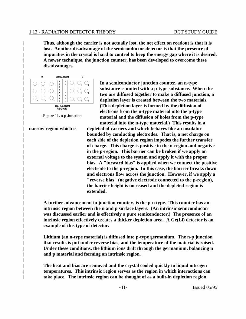
In a semiconductor junction counter, an n-type|substance is united with a p-type substance. When the|two are diffused together to make a diffused junction, a|depletion layer is created between the two materials. |(This depletion layer is formed by the diffusion of|electrons from the n-type material into the p-type|material and the diffusion of holes from the p-type|material into the n-type material.) This results in a|
narrow region which is depleted of carriers and which behaves like an insulator|bounded by conducting electrodes. That is, a net charge on|each side of the depletion region impedes the further transfer|of charge. This charge is positive in the n-region and negative|in the p-region. This barrier can be broken if we apply an|external voltage to the system and apply it with the proper|bias. A "forward bias" is applied when we connect the positive|electrode to the p-region. In this case, the barrier breaks down|and electrons flow across the junction. However, if we apply a|"reverse bias" (negative electrode connected to the p-region),|the barrier height is increased and the depleted region is|extended.|
|A further advancement in junction counters is the p-n type. This counter has an|intrinsic region between the n and p surface layers. (An intrinsic semiconductor|was discussed earlier and is effectively a pure semiconductor.) The presence of an|intrinsic region effectively creates a thicker depletion area. A Ge(Li) detector is an|example of this type of detector.|
|Lithium (an n-type material) is diffused into p-type germanium. The n-p junction|that results is put under reverse bias, and the temperature of the material is raised. |Under these conditions, the lithium ions drift through the germanium, balancing n|and p material and forming an intrinsic region.|
|The heat and bias are removed and the crystal cooled quickly to liquid nitrogen|temperatures. This intrinsic region serves as the region in which interactions can|take place. The intrinsic region can be thought of as a built-in depletion region.|
1.13 - RADIATION DETECTOR THEORY RCT STUDY GUIDE
-42- Issued 05/95
Due to the large size of the depletion region and the reduced mobility of the|electrons and holes due to the depressed temperature, a high charge is necessary to|cause conduction. The charge is chosen high enough to collect ion pairs, but low|enough to prevent noise.|
|Due to the increased stopping power of germanium over air at -321 F the energy| o
required to create an ion pair is only 2.96 eV compared to 33.7 eV for air. This|means that by theory, a germanium detector will respond to any radiation that will|create ion pairs. In actuality, however, the response to radiations other than gamma|is limited by the materials surrounding the detector, material necessary to maintain|temperature. Another consideration limiting response is the geometry of the crystal.|The most efficient response occurs when the interaction takes place in the center of|the intrinsic region, this can only occur for gamma.|
|Radiation interacts with atoms in the intrinsic region to produce electron hole pairs. |The presence of ion pairs in the depletion region causes current flow. This is similar|to a transistor, in that instead of inducing charges in the center section (the base in a|transistor) by a battery or an other source, the charge is induced by the creation of|ion pairs. Since it is not necessary for the ion produced to reach the p and n region|to be collected, as in a gas filled chamber, the response is faster.|
|Since the number of ion pairs produced is a function of the incident energy, and the|resulting current is a function of the amount of ion pairs, Ge(Li) response is in terms|of energy.|
||
GeLi Systems||
A typical Ge(Li) detector system consists of a vacuum enclosed Ge(Li) crystal which|is coaxial in shape and attached to a copper cold finger through an agate insulator. |The crystal is under a vacuum to prevent frost forming on the crystal, and damage|caused by impurities in the air. The cold finger is immersed in liquid nitrogen in a|dewar.|
|The crystal is subject to failure should its temperature be raised to room|temperature due to lithium ion drift and increased electron noise.|
|Advantages of Ge(Li) Detectors|
|GeLi detectors offer an advantage of high resolution (i.e. the ability to differentiate|between closely adjacent gamma photopeaks. It can resolve the 3 photopeaks of|
Zr/Nb whereas this would appear as 1 photopeak with NaI(Tl) detectors.| 95
1.13 - RADIATION DETECTOR THEORY RCT STUDY GUIDE
-43- Issued 05/95
GeLi also has a short response time and a more linear energy response than NaI(Tl).||
Small size crystals offer the best resolution but the efficiency of detection is lowered.||
Disadvantages of Ge(Li) Detectors||
GeLi systems can only be used for gamma photon detection. A cryogenic (liquid|nitrogen) system is required to cool the detector and this adds to the initial cost as|well as a continuing operation cost.|
|Because detectors are presently limited to less than 100-300 cc in size, the efficiency|of counting is low compared to NaI. Counting times in excess of 1,000 minutes are|necessary for environmental samples.|
||
Intrinsic Germanium Detectors||
One of the major disadvantages of GeLi detectors is the requirement that the crystal|must always be kept cooled by liquid nitrogen. If the detector is ever allowed to|reach room temperature, the lithium ions will drift and an effective|intrinsic/depletion region (the area of electron-hole pair formation) will no longer|exist. The detector can be returned to the manufacturer for redrifting, but the|process is expensive and time consuming. The detector may be less efficient than|before the redrifting. The bulky size of the liquid nitrogen dewar also places|limitations on the uses of a GeLi detector. A semiconductor detector that could be|operated and/or stored at room temperature would have advantages for use in|installed effluent monitors or portable units.|
|Principles of Operation|
|In natural germanium of normal purity, the depletion region is only a few|millimeters thick. The crystal is, in effect, a conductor due to the impurities in the|crystal. Resistance is very low in the crystal, and detected electron flow (noise) may|be caused by conditions other than radiation (e.g., heat). As a result, the natural|crystal is virtually useless for radiation detection.|
|The use of the lithium drifting process in GeLi detectors creates an artificial|depletion/intrinsic zone of 10-15 mm. The GeLi detector is a semiconductor. The|resistance is greater than the resistance for a natural germanium crystal, and by|applying the correct voltage to the crystal, most non-radiation events that induce|electron flow can be eliminated. GeLi detectors are used in radiation detection;|however, the crystal must be maintained at the temperature of liquid nitrogen to|

1.13 - RADIATION DETECTOR THEORY RCT STUDY GUIDE
-44- Issued 05/95
maintain the depletion/intrinsic zone.||
If an extremely pure germanium crystal is created, the crystal's resistance will be|sufficiently big so that a depletion region of 10mm can be obtained by using a|reverse bias voltage, instead of drifting lithium through the germanium as is done in|GeLi detectors. This pure germanium crystal would have, like GeLi crystals,|semiconductor properties, and by applying the correct voltage could be used to|collect electrons induced by radiation. Recently, processes for creating germanium|in a very high state of purity have been developed. This, in turn, has led to the|development of a semiconductor that can be stored at room temperature. The pure|germanium crystals are usually called "intrinsic germanium" or "high purity|germanium" (abbreviated HPGe) detectors. HPGe crystals are perhaps the most|highly purified material that has even been produced.|
|Note that in the above paragraph it was stated that the HPGe crystals could be|stored at room temperature. This is because HPGe crystals are not lithium drifted.|However, there was no mention of operating detectors with the crystals at room|temperature. In order to reduce unwanted detector noise (caused by reduced|resistance at room temperature) the detector must be operated at the temperature of|liquid nitrogen. Experience has shown that the crystals can be cycled between room|and cold temperatures without damage. Most manufacturers, however, recommend|that the detectors be continuously maintained at liquid nitrogen temperatures if|possible.|
|Advantages of HPGe's|
|The dewar used for storing the liquid nitrogen coolant for HPGe detectors can be|smaller than the dewar used for GeLi detectors. HPGe detectors are more portable. |The main advantage is that should the detector be allowed to rise to room|temperature (with no voltage applied) the detector need only be returned to and|stabilized at liquid nitrogen temperatures to be used.|
|Disadvantages of HPGe's|
|Even though the dewar is smaller for the HPGe detector they still require liquid|nitrogen cooling and tend to be fairly expensive.|
|
1.13 - RADIATION DETECTOR THEORY RCT STUDY GUIDE
-45- Issued 05/95
CONDENSER R-METER AND CHAMBER||
Method of Detection||
The condenser chamber is an integrating, air wall tissue equivalent ionization|chamber used to measure exposure to X or gamma radiation. The chamber|generally consists of a Bakelite shell, coated on the inner surface with graphite to|make it conducting, and an insulated central electrode. The chamber is mounted at|one end of a shielded stem containing a solid dielectric storage condenser. The|chambers vary is size and shape depending on their exposure range. The smaller|the chamber volume the higher the exposure it is capable of measuring.|
|The Condenser R-Meter performs two functions. It applies a charge to the chamber|and, after exposure, serves as a read-out device to determine the amount of|exposure. It contains a line-operated d.c. power supply, which provides a charging|voltage of approximately 500 volts. The read-out device is a string electrometer. |Functionally, this is a d.c. voltmeter with infinite input resistance. It is a descendant|of the gold leaf electroscope which was used as a detector in the early days of|radiation physics. Instead of a gold leaf, this instrument uses a platinum coated|quartz fiber, bent into a horseshoe shape and soldered at each end to a horseshoe|shaped support. When a charge is applied to the fiber support and a nearby|deflecting electrode, the fiber is attracted toward the electrode to an extent|proportional to the applied charge. A small light bulb casts a shadow of the fiber on|a scale, which is observed through an optical system. In operation, the chamber is|connected to the charger-reader, the charging switch is rotated to "charge" and the|electrometer is adjusted to zero on the scale. This puts a full charge on the chamber,|which can then be disconnected and placed wherever exposure is to be measured. |After the exposure, the chamber is again plugged into the charger-reader and the|residual charge is read. Since the loss of charge is proportional to the exposure, the|scale can be calibrated in roentgens.|
|The Condenser R-Meter is a secondary standard. It must be calibrated against a|primary standard, the free-air chamber. The Condenser R-Meter, in turn, can be|used to calibrate other survey instruments. The protective cap must always be on|the chamber when the exposure is made.|
|Range|
|Condenser chambers vary in size. The total exposure a chamber measures decreases|as the chamber volume increases. Chambers are generally available which enable us|to cover exposure ranges from several mR up to 250 R.|
|
1.13 - RADIATION DETECTOR THEORY RCT STUDY GUIDE
-46- Issued 05/95
|Energy Response|
|Condenser chambers vary in wall material and thickness as well as in size. The|choice of wall material and thickness off-sets the energy dependence of the|chambers.|
|Use|
|The condenser chambers are generally used to calibrate X and gamma radiation|sources, and for making surveys of X-ray equipment. Condenser chambers may|also be used to measure neutron radiation. Some chambers are boron lined and|measure the ionization from the alpha particles emitted in the boron-thermal|neutron reaction.|
|Other chambers are made of tissue equivalent material to measure the absorbed|dose of any ionizing radiation.|
||
REFERENCES||
1. "Basic Radiation Protection Technology"; Gollnick, Daniel; Pacific|Radiation Press; 1983|
2. ANL-88-26 (1988) "Operational Health Physics Training"; Moe, Harold;|Argonne National Laboratory, Chicago|
3. "Radiation Detection and Measurement"; Knoll, Glenn F. John; Wiley &|Sons; 1979|
||
Related Documents