RE 15199/03.2017, Bosch Rexroth AG Features ▶ Hydrobase motor ▶ Optimised design for integration ▶ Compact installation in customer structure ▶ High volumetric and mechanical efficiencies ▶ High reliability ▶ Low maintenance ▶ Smooth running at very low speeds ▶ Low noise ▶ Bi-directional ▶ Freewheeling possible ▶ Available with: – Holding brake (multi-disc) – Bi-directional two speed – Integrated flushing valve – Speed sensor ▶ Frame size MCR3, MCR5, MCR10, MCR15, MCR20 ▶ Displacement 160 cc to 3000 cc ▶ Differential pressure up to 450 bar ▶ Torque output up to 19099 Nm ▶ Speed up to 875 rpm ▶ Open and closed circuits Radial piston motor for integrated drives MCR-H RE 15199 Edition: 03.2017 Replaces: 12.2013 Contents Functional description 2 Ordering code 5 Technical data 7 Efficiencies 9 Dimensions 10 Selection guide 16

Welcome message from author
This document is posted to help you gain knowledge. Please leave a comment to let me know what you think about it! Share it to your friends and learn new things together.
Transcript

RE 15199/03.2017, Bosch Rexroth AG
Features ▶ Hydrobase motor ▶ Optimised design for integration ▶ Compact installation in customer structure ▶ High volumetric and mechanical effi ciencies ▶ High reliability ▶ Low maintenance ▶ Smooth running at very low speeds ▶ Low noise ▶ Bi-directional ▶ Freewheeling possible ▶ Available with:
– Holding brake (multi-disc) – Bi-directional two speed – Integrated fl ushing valve – Speed sensor
▶ Frame size MCR3, MCR5, MCR10, MCR15, MCR20 ▶ Displacement 160 cc to 3000 cc ▶ Diff erential pressure up to 450 bar ▶ Torque output up to 19099 Nm ▶ Speed up to 875 rpm ▶ Open and closed circuits
Radial piston motor for integrated drivesMCR-H
RE 15199Edition: 03.2017Replaces: 12.2013
ContentsFunctional description 2Ordering code 5Technical data 7Effi ciencies 9Dimensions 10Selection guide 16
Bosch Rexroth AG, RE 15199/03.2017
2 MCR-H | Radial piston motor for integrated drivesFunctional description
Functional description
Hydraulic motors of the type MCR-H are radial piston motors with a hydraulic rotary group as the base (Hydro-base) and a rear case sub assembly. These motors are intended for various integrated drive applications in open or closed circuits where the front case, shaft and bearing arrangement of the motor are provided by the customer structure. Some of the applications in which these motors are used are construction machinery, fork lift trucks, for-estry machines and industrial applications. The compact design allows installation to very confi ned spaces and contributes in weight savings.
ConstructionRear case (2), rotary group (3, 4, 8), cam (5) and fl ow distributor (7)
TransmissionThe cylinder block (4) is connected to the shaft located in the customer structure to which the motor is mounted by means of splines. The pistons (3) are arranged radially in the cylinder block (4) and make contact with the cam (5) via rollers (8).
Torque generation
Working stroke
Return stroke
Feed Return
The number of working and return strokes corresponds to the number of lobes on the cam multiplied by number of pistons in the cylinder block.
Flow pathsThe ports A and B, which are located in the rear case, carry oil through the distributor to the cylinder chambers (E).
FreewheelingIn certain applications there may be a requirement to free-wheel the motor. This may be achieved by connecting ports A and B to zero pressure and simultaneously applying a pressure of 2 bar to the housing through port L. In this condition, the pistons are forced into the cylinder block which forces the rollers to lose contact with the cam thus allowing free rotation of the shaft.
5 7 D D E
53
A
8 2
B
4
RE 15199/03.2017, Bosch Rexroth AG
Radial piston motor for integrated drives | MCR-H Functional description
3
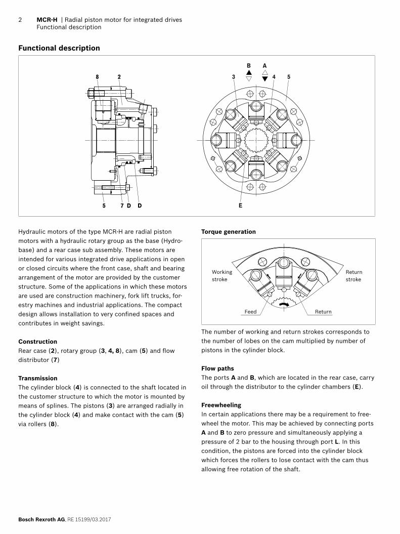
Two speed operation (2W)In mobile applications where vehicles are required to oper-ate at high speed with low motor loads, the motor can be switched to a low-torque and high-speed mode. This is achieved by operating an integrated valve which directs hydraulic fl uid to only one half of the motor while continu-ously re-circulating the fl uid in the other half. This “reduced displacement” mode reduces the fl ow required for a given speed and gives the potential for cost and effi ciency improvements. The motor maximum speed remains unchanged.Bosch Rexroth has developed a special spool valve to allow smooth switching to reduced displacement whilst on the move. This is known as “soft-shift” and is a standard fea-ture of 2W motors. The spool valve requires either an addi-tional sequence valve or electro-proportional control to operate in “soft-shift” mode.
▼ Schematic
ABXL
15 bar
12 bar
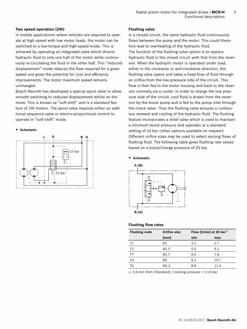
Flushing valveIn a closed circuit, the same hydraulic fl uid continuously fl ows between the pump and the motor. This could there-fore lead to overheating of the hydraulic fl uid.The function of the fl ushing valve option is to replace hydraulic fl uid in the closed circuit with that from the reser-voir. When the hydraulic motor is operated under load, either in the clockwise or anti-clockwise direction, the fl ushing valve opens and takes a fi xed fl ow of fl uid through an orifi ce from the low pressure side of the circuit. This fl ow is then fed to the motor housing and back to the reser-voir normally via a cooler. In order to charge the low pres-sure side of the circuit, cool fl uid is drawn from the reser-voir by the boost pump and is fed to the pump inlet through the check valve. Thus the fl ushing valve ensures a continu-ous renewal and cooling of the hydraulic fl uid. The fl ushing feature incorporates a relief valve which is used to maintain a minimum boost pressure and operates at a standard setting of 14 bar (other options available on request). Diff erent orifi ce sizes may be used to select varying fl ows of fl ushing fl uid. The following table gives fl ushing rate values based on a boost/charge pressure of 25 bar.
▼ Schematic
A (B)
B (A)
Flushing fl ow rates
Flushing code Orifi ce size Flow [l/min] at 25 bar1)
[mm] min max
F1 Ø1 2.2 2.7
F2 Ø1.5 5.0 6.1
F7 Ø1.7 6.4 7.8
F4 Ø2 8.2 10.7
F6 Ø2.3 8.8 11.4
1) 0.6 mm Shim (Standard), Cracking pressure = 11±3 bar
Bosch Rexroth AG, RE 15199/03.2017
4 MCR-H | Radial piston motor for integrated drivesFunctional description
Holding brake (multi-disc brake)
MountingBy way of rear housing (2) and brake shaft (14).
Brake applicationAs a safety requirement in mobile applications a parking brake may be provided to ensure that the motor cannot turn when the machine is not in use. The parking brake provides holding torque by means of discs (11) that are compressed by a disc spring (10). The brake is released when oil pressure is applied to brake port “Z” and the pressure in the annular area (9) compresses the disc spring using brake piston (12) thus allowing the brake discs (11) to turn independently.
NoticeBrakes not for dynamic use!
▼ Schematic diagrams
Motor without brake
Motor with holding brake
A
B L
ZA
B L
Manual release of holding brakeThe brake may also be released manually by loosening screws (13).
2 9
12
10
13
11
14
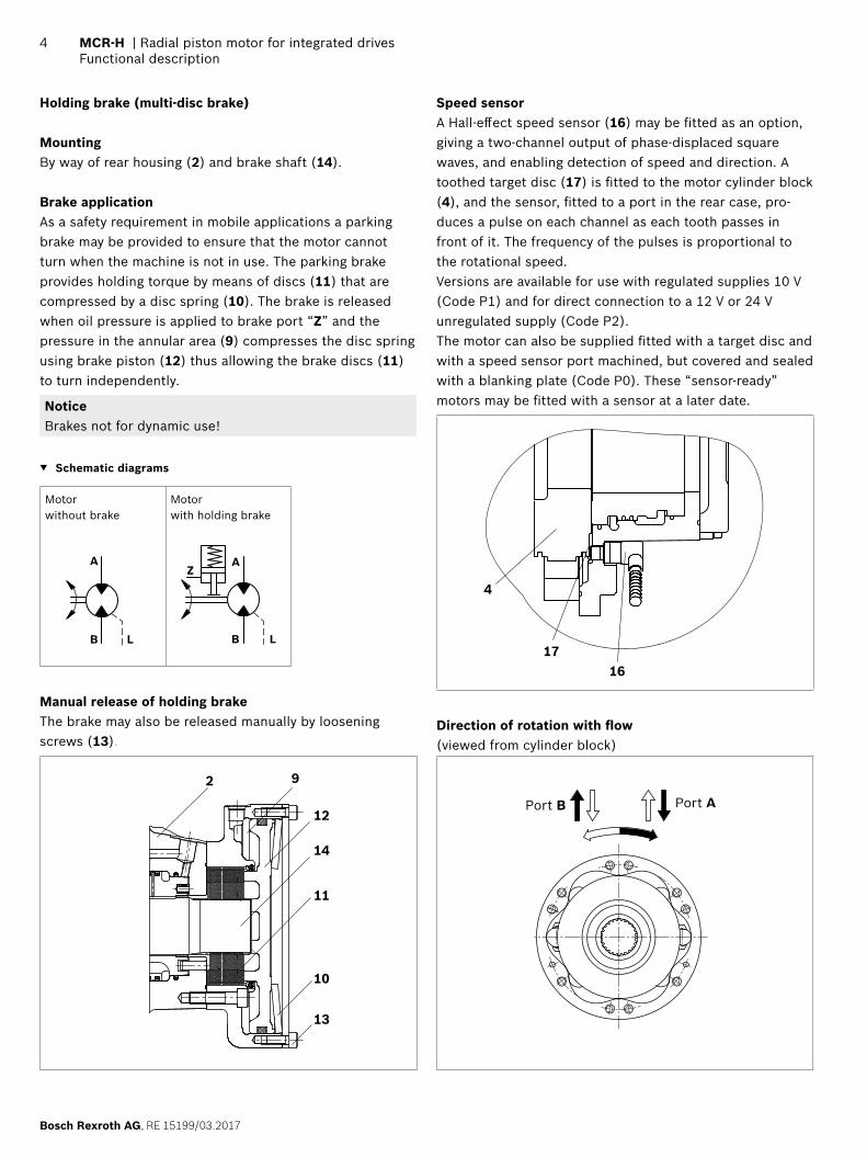
Speed sensorA Hall-eff ect speed sensor (16) may be fi tted as an option, giving a two-channel output of phase-displaced square waves, and enabling detection of speed and direction. A toothed target disc (17) is fi tted to the motor cylinder block (4), and the sensor, fi tted to a port in the rear case, pro-duces a pulse on each channel as each tooth passes in front of it. The frequency of the pulses is proportional to the rotational speed.Versions are available for use with regulated supplies 10 V (Code P1) and for direct connection to a 12 V or 24 V unregulated supply (Code P2).The motor can also be supplied fi tted with a target disc and with a speed sensor port machined, but covered and sealed with a blanking plate (Code P0). These “sensor-ready” motors may be fi tted with a sensor at a later date.
1716
4
Direction of rotation with fl ow(viewed from cylinder block)
Port APort B

RE 15199/03.2017, Bosch Rexroth AG
Radial piston motor for integrated drives | MCR-H Ordering code
5
Ordering code
01 02 03 04 05 06 07 08 09 10 11 12 13 14 15 16
MCR H Z / 33 S
Radial piston motor01 Radial-piston type, low-speed, high-torque motor MCR
Frame size02 Frame size 3 3
5 5
10 10
15 15
20 20
Housing type03 Hydrobase motor H
Nominal size, displacement Vg in cm3/rev04 Frame size 3 160 225 255 280 325 365 400
Low displacement: motors use standard cylindrical pistons LD ● ● ● ● – – –
High displacement: motors use stepped pistons HD – – – – ● ● ●
Frame size 5 380 470 520 565 620 680 750 820Low displacement: motors use standard cylindrical pistons LD ● ● ● ● – – – –
High displacement: motors use stepped pistons HD – – – – ● ● ● ●
Frame size 10 780 860 940 1120 1250 1340Low displacement: motors use standard cylindrical pistons LD ● ● ● – – –
High displacement: motors use stepped pistons HD – – – ● ● ●
Frame size 15 1130 1250 1500 1780 2150Low displacement: motors use standard cylindrical pistons LD ● ● ● – –
High displacement: motors use stepped pistons HD – – – ● ●
Frame size 20 1750 2100 2500 3000Low displacement: motors use standard cylindrical pistons LD ● ● – –
High displacement: motors use stepped pistons HD – – ● ●
Drive shaft05 Without drive shaft Z
Rear shaft06 Without rear shaft Z
Series07 Series 33 331)
Brake MCR3 MCR5 MCR10 MCR15 MCR2008 Without brake ● ● ● ● ● A0
Hydraulic release spring applied multi-disc holding brake
2200 Nm ● ● – – – B2
4400 Nm – ● – – – B4
4400 Nm – – ● – – B5
7000 Nm – – ● – – B7
11000 Nm – – – ● – B11
19000 Nm – – – – ● B19
● = Available – = Not available
1) This data sheet also applies series 32.

Bosch Rexroth AG, RE 15199/03.2017
6 MCR-H | Radial piston motor for integrated drivesOrdering code
Seals09 NBR (nitrile rubber) M
FKM (fl uoroelastomer / Viton) V
Single/two-speed operation MCR3 MCR5 MCR10 MCR15 MCR2010 Single speed, standard direction of rotation ● ● ● ● ● 1L
Bi-directional two speed, standard direction of rotation ● ● ● – ● 2WL
Ports MCR3 MCR5 MCR10 MCR15 MCR2011 Tapped with UNF thread (SAE J514) ● ● – – – 12
Tapped with UNF thread (SAE J514) (A and B ports SAE split fl ange metric bolt holes)
– – ● ● – 42
BSP threaded ports(A and B ports SAE split fl ange metric bolt holes)
– – – – ● 11
Studs12 With wheel studs and nuts S
Speed sensor13 Without sensor (no code)
Sensor ready P0
Sensor without regulator P1
Sensor with regulator P2
Flushing14 Without fl ushing (no code)
With fl ushing (see table on page 3) F1-F7
Special order15 Special feature SOXXX
Other16 Mark in text here *
● = Available – = Not available
01 02 03 04 05 06 07 08 09 10 11 12 13 14 15 16
MCR H Z / 33 S
Footer from page 71) Ensure motor case is fi lled with oil prior to start-up. 2) For installation and maintenance details, please see instruction
manual 15215-B.3) For any other fl uid type contact the Engineering Department at
Bosch Rexroth, Glenrothes. For more information on hydraulic fl u-ids, see datasheets 90220 and 90223.
4) Extension of the allowable temperature range may be possible de-pending on specifi cation. Please consult Bosch Rexroth Engineer-ing Department in Glenrothes for further details.
5) Maximum values should only be applied for a small portion of the duty cycle. Please consult Bosch Rexroth Engineering Department in Glenrothes for motor life calculations based on particular oper-ating cases.
6) When operating motors in series, please consult Bosch Rexroth Engineering Department in Glenrothes.
7) For continuous operation at speeds <5 rpm please consult Bosch Rexroth Engineering Department in Glenrothes.
8) Based on nominal no-load Δp of 20 bar in full-displacement mode.9) Warning! During the running in period of the motor (min. 20 hrs) it
should not be run unloaded at >100 rpm.
RE 15199/03.2017, Bosch Rexroth AG
Radial piston motor for integrated drives | MCR-H Technical data
7
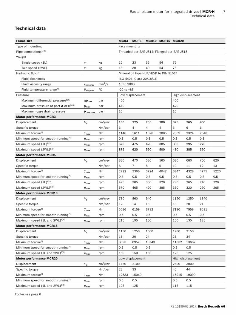
Technical data
Frame size MCR3 MCR5 MCR10 MCR15 MCR20
Type of mounting Face mounting
Pipe connections1)2) Threaded per SAE J514; Flanged per SAE J518
Weight
Single speed (1L) m kg 12 23 36 54 76
Two speed (2WL) m kg 18 30 40 54 76
Hydraulic fl uid3) Mineral oil type HLP/HLVP to DIN 51524
Fluid cleaniness ISO 4406, Class 20/18/15
Fluid viscosity range νmin/max mm²/s 10 to 2000
Fluid temperature range4) θmin/max °C -20 to +85
Pressure Low displacement High displacement
Maximum diff erential pressure5)6) Δpmax bar 450 400
Maximum pressure at port A or B5)6) pmax bar 470 420
Maximum case drain pressure pcase max bar 10 10
Motor performance MCR3
Displacement Vg cm3/rev 160 225 255 280 325 365 400
Specifi c torque Nm/bar 3 4 4 4 5 6 6
Maximum torque5) Tmax Nm 1146 1611 1826 2005 2069 2324 2546
Minimum speed for smooth running7) nmin rpm 0.5 0.5 0.5 0.5 0.5 0.5 0.5
Maximum speed (1L)8)9) nmax rpm 670 475 420 385 330 295 270
Maximum speed (2WL)8)9) nmax rpm 875 620 550 500 430 385 350
Motor performance MCR5
Displacement Vg cm3/rev 380 470 520 565 620 680 750 820
Specifi c torque Nm/bar 6 7 8 9 10 11 12 13
Maximum torque5) Tmax Nm 2722 3366 3724 4047 3947 4329 4775 5220
Minimum speed for smooth running7) nmin rpm 0.5 0.5 0.5 0.5 0.5 0.5 0.5 0.5
Maximum speed (1L)8)9) nmax rpm 475 385 350 320 290 265 240 220
Maximum speed (2WL)8)9) nmax rpm 570 465 420 385 350 320 290 265
Motor performance MCR10
Displacement Vg cm3/rev 780 860 940 1120 1250 1340
Specifi c torque Nm/bar 12 14 15 18 20 21
Maximum torque5) Tmax Nm 5586 6159 6732 7130 7958 8531
Minimum speed for smooth running7) nmin rpm 0.5 0.5 0.5 0.5 0.5 0.5
Maximum speed (1L and 2WL)8)9) nmax rpm 215 195 180 150 135 125
Motor performance MCR15
Displacement Vg cm3/rev 1130 1250 1500 1780 2150
Specifi c torque Nm/bar 18 20 24 28 34
Maximum torque5) Tmax Nm 8093 8952 10743 11332 13687
Minimum speed for smooth running7) nmin rpm 0.5 0.5 0.5 0.5 0.5
Maximum speed (1L and 2WL)8)9) nmax rpm 150 150 150 125 125
Motor performance MCR20 Low displacement High displacement
Displacement Vg cm3/rev 1750 2100 2500 3000
Specifi c torque Nm/bar 28 33 40 44
Maximum torque5) Tmax Nm 12533 15040 15915 19099
Minimum speed for smooth running7) nmin rpm 0.5 0.5 0.5 0.5
Maximum speed (1L and 2WL)8)9) nmax rpm 125 125 115 115
Footer see page 6
Bosch Rexroth AG, RE 15199/03.2017
8 MCR-H | Radial piston motor for integrated drivesTechnical data
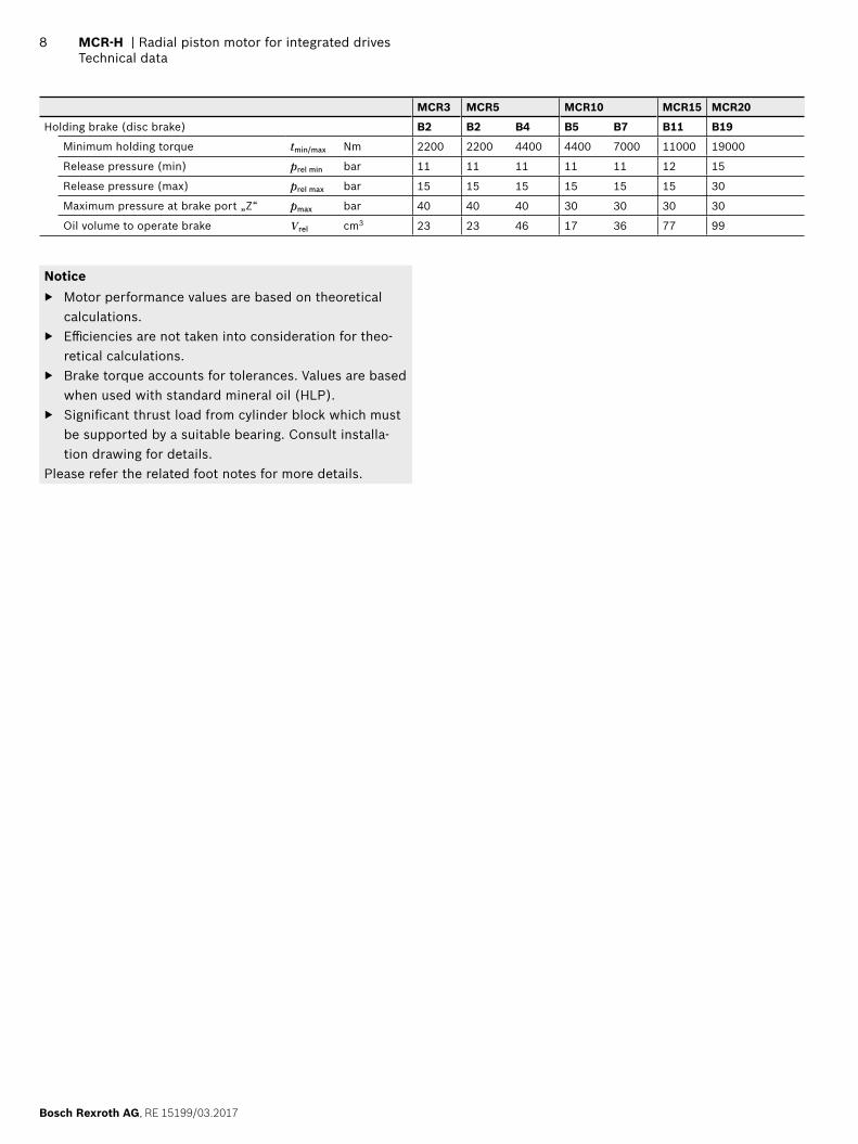
MCR3 MCR5 MCR10 MCR15 MCR20
Holding brake (disc brake) B2 B2 B4 B5 B7 B11 B19
Minimum holding torque tmin/max Nm 2200 2200 4400 4400 7000 11000 19000
Release pressure (min) prel min bar 11 11 11 11 11 12 15
Release pressure (max) prel max bar 15 15 15 15 15 15 30
Maximum pressure at brake port „Z“ pmax bar 40 40 40 30 30 30 30
Oil volume to operate brake Vrel cm3 23 23 46 17 36 77 99
Notice ▶ Motor performance values are based on theoretical
calculations. ▶ Effi ciencies are not taken into consideration for theo-
retical calculations. ▶ Brake torque accounts for tolerances. Values are based
when used with standard mineral oil (HLP). ▶ Signifi cant thrust load from cylinder block which must
be supported by a suitable bearing. Consult installa-tion drawing for details.
Please refer the related foot notes for more details.

RE 15199/03.2017, Bosch Rexroth AG
Radial piston motor for integrated drives | MCR-H Effi ciencies
9
Effi ciencies
▼ Mechanical effi ciency
40
20
00 0.4 0.80.2 0.6 1.0
60
80
100
Speed n/nmax
Mec
hani
cal e
ffi ci
ency
[%
]
▼ Volumetric effi ciency
40
60
100
20
0
120
100 bar / 1450 psi300 bar / 4350 psi
0 0.4 0.80.2 0.6 1.0
80
Speed n/nmax
Volu
met
ric
effi c
ienc
y [%
]
NoticeFor specifi c performance information or operating conditions contact the Engineering Department at Bosch Rexroth, Glenrothes.
▼ Charge pressure
0 0.4 0.80.2 0.6 1.0
6
2
8
14
4
10
12
0
Speed n/nmax
Min
imum
cha
rge
pres
sure
[ba
r]

Bosch Rexroth AG, RE 15199/03.2017
10 MCR-H | Radial piston motor for integrated drivesDimensions
Dimensions [mm]
Dimensions
MCR-H single speed (1L)
A BA, B
L L
L7
L1
L5
L6
L4
L3
S1S2
L2
D1
D2
D3
D4
Speed sensor
Motor D1 D2 D3 D4 L1 L2 L3 L4 L5 L6 L7
MCR3 ø180 ø131 ø50 ø156 105 95 83 71 9 48 66.5
MCR5 ø223 ø166.3 ø65.25 ø196 130 119 103 103 6.5 68 76
MCR10 ø264 ø192 ø81.13 ø223 167 141.5 125 105.5 9.4 63.5 102
MCR15 ø304 ø229 ø96.5 ø304 173.4 156.7 141 116 10 84.5 115
MCR20 ø345 ø260 ø108.25 ø310 217.7 173.8 129 129 15.5 81 120
Motor S1 S2 Spline
MCR3 63.5 90° BS3550 class 1 fi llet root side fi t, pitch 24/48, PCD 38.1 mm, No of spaces 36
MCR5 75 45° N50 x 2 x 24 x 9H DIN 5480
MCR10 89 45° N65 x 2 x 31 x 9H DIN 5480
MCR15 103 45° N75 x 2 x 36 x 9H DIN 5480
MCR20 125 45° N90 x 2 x 44 x 9H DIN 5480
Before fi nalizing your design, request a binding installation drawing.
Spline
RE 15199/03.2017, Bosch Rexroth AG
Radial piston motor for integrated drives | MCR-H Dimensions
11
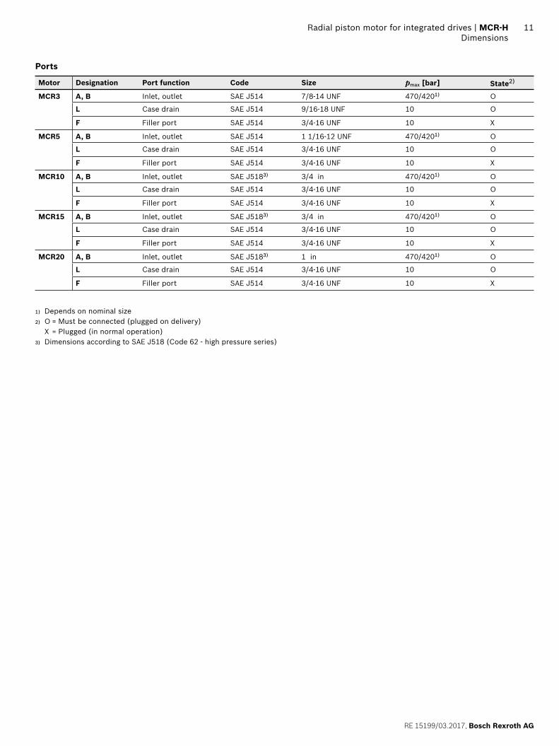
Ports
Motor Designation Port function Code Size pmax [bar] State2)
MCR3 A, B Inlet, outlet SAE J514 7/8-14 UNF 470/4201) O
L Case drain SAE J514 9/16-18 UNF 10 O
F Filler port SAE J514 3/4-16 UNF 10 X
MCR5 A, B Inlet, outlet SAE J514 1 1/16-12 UNF 470/4201) O
L Case drain SAE J514 3/4-16 UNF 10 O
F Filler port SAE J514 3/4-16 UNF 10 X
MCR10 A, B Inlet, outlet SAE J5183) 3/4 in 470/4201) O
L Case drain SAE J514 3/4-16 UNF 10 O
F Filler port SAE J514 3/4-16 UNF 10 X
MCR15 A, B Inlet, outlet SAE J5183) 3/4 in 470/4201) O
L Case drain SAE J514 3/4-16 UNF 10 O
F Filler port SAE J514 3/4-16 UNF 10 X
MCR20 A, B Inlet, outlet SAE J5183) 1 in 470/4201) O
L Case drain SAE J514 3/4-16 UNF 10 O
F Filler port SAE J514 3/4-16 UNF 10 X
1) Depends on nominal size2) O = Must be connected (plugged on delivery)
X = Plugged (in normal operation)3) Dimensions according to SAE J518 (Code 62 - high pressure series)
Bosch Rexroth AG, RE 15199/03.2017
12 MCR-H | Radial piston motor for integrated drivesDimensions
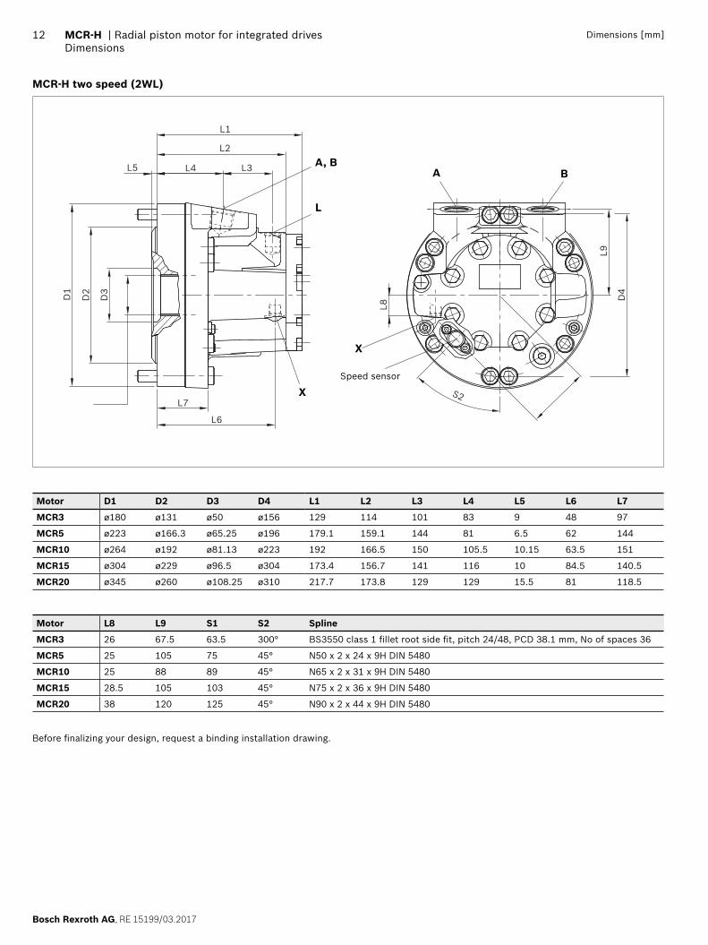
Dimensions [mm]
MCR-H two speed (2WL)
L1
L8S2
L9
L2
L4
L7
L6
L3L5
D1
D2
D3
D4
A, B
L
X
A B
XSpeed sensor
Motor D1 D2 D3 D4 L1 L2 L3 L4 L5 L6 L7
MCR3 ø180 ø131 ø50 ø156 129 114 101 83 9 48 97
MCR5 ø223 ø166.3 ø65.25 ø196 179.1 159.1 144 81 6.5 62 144
MCR10 ø264 ø192 ø81.13 ø223 192 166.5 150 105.5 10.15 63.5 151
MCR15 ø304 ø229 ø96.5 ø304 173.4 156.7 141 116 10 84.5 140.5
MCR20 ø345 ø260 ø108.25 ø310 217.7 173.8 129 129 15.5 81 118.5
Motor L8 L9 S1 S2 Spline
MCR3 26 67.5 63.5 300° BS3550 class 1 fi llet root side fi t, pitch 24/48, PCD 38.1 mm, No of spaces 36
MCR5 25 105 75 45° N50 x 2 x 24 x 9H DIN 5480
MCR10 25 88 89 45° N65 x 2 x 31 x 9H DIN 5480
MCR15 28.5 105 103 45° N75 x 2 x 36 x 9H DIN 5480
MCR20 38 120 125 45° N90 x 2 x 44 x 9H DIN 5480
Before fi nalizing your design, request a binding installation drawing.
RE 15199/03.2017, Bosch Rexroth AG
Radial piston motor for integrated drives | MCR-H Dimensions
13
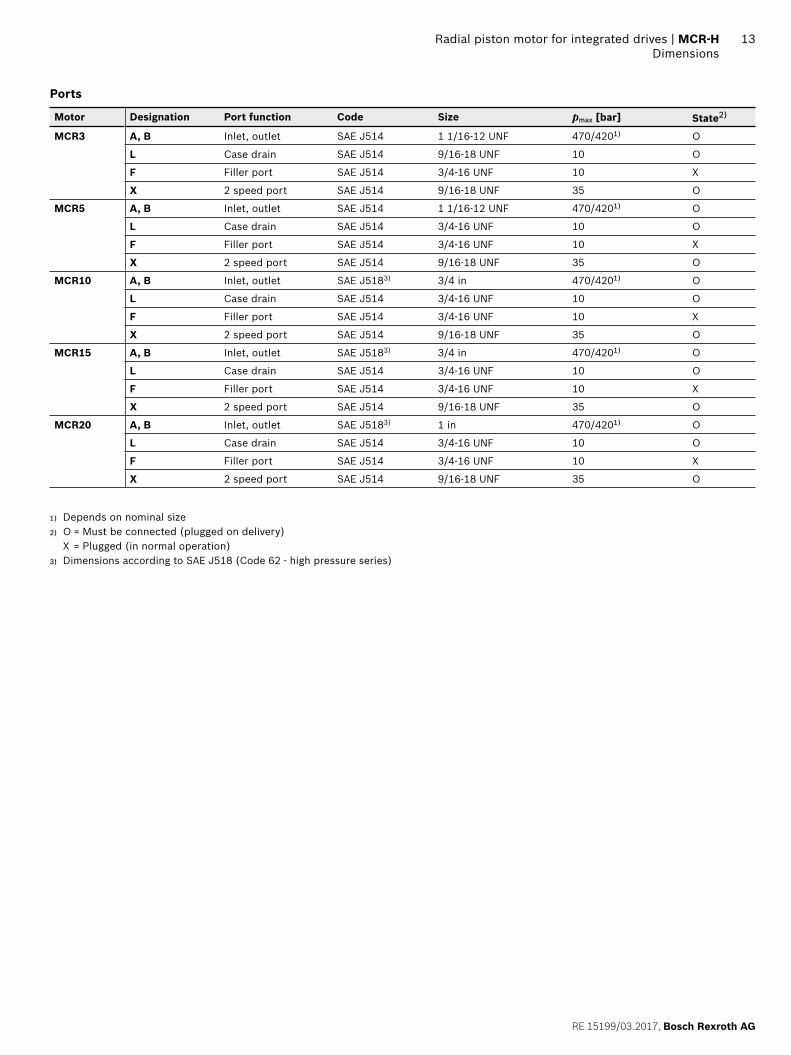
Ports
Motor Designation Port function Code Size pmax [bar] State2)
MCR3 A, B Inlet, outlet SAE J514 1 1/16-12 UNF 470/4201) O
L Case drain SAE J514 9/16-18 UNF 10 O
F Filler port SAE J514 3/4-16 UNF 10 X
X 2 speed port SAE J514 9/16-18 UNF 35 O
MCR5 A, B Inlet, outlet SAE J514 1 1/16-12 UNF 470/4201) O
L Case drain SAE J514 3/4-16 UNF 10 O
F Filler port SAE J514 3/4-16 UNF 10 X
X 2 speed port SAE J514 9/16-18 UNF 35 O
MCR10 A, B Inlet, outlet SAE J5183) 3/4 in 470/4201) O
L Case drain SAE J514 3/4-16 UNF 10 O
F Filler port SAE J514 3/4-16 UNF 10 X
X 2 speed port SAE J514 9/16-18 UNF 35 O
MCR15 A, B Inlet, outlet SAE J5183) 3/4 in 470/4201) O
L Case drain SAE J514 3/4-16 UNF 10 O
F Filler port SAE J514 3/4-16 UNF 10 X
X 2 speed port SAE J514 9/16-18 UNF 35 O
MCR20 A, B Inlet, outlet SAE J5183) 1 in 470/4201) O
L Case drain SAE J514 3/4-16 UNF 10 O
F Filler port SAE J514 3/4-16 UNF 10 X
X 2 speed port SAE J514 9/16-18 UNF 35 O
1) Depends on nominal size2) O = Must be connected (plugged on delivery)
X = Plugged (in normal operation)3) Dimensions according to SAE J518 (Code 62 - high pressure series)
Bosch Rexroth AG, RE 15199/03.2017
14 MCR-H | Radial piston motor for integrated drivesDimensions
Dimensions [mm]
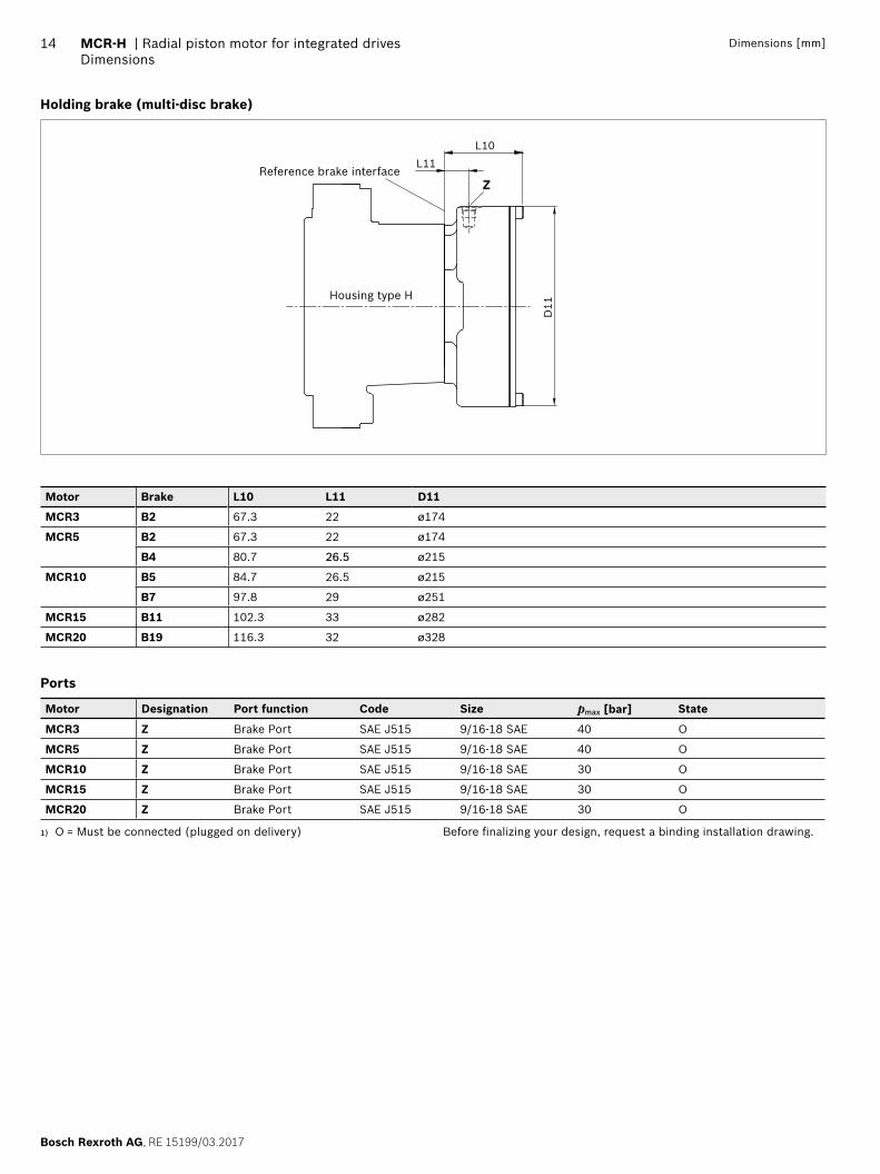
Holding brake (multi-disc brake)
L10L11
Z
D11
Reference brake interface
Motor Brake L10 L11 D11
MCR3 B2 67.3 22 ø174
MCR5 B2 67.3 22 ø174
B4 80.7 26.5 ø215
MCR10 B5 84.7 26.5 ø215
B7 97.8 29 ø251
MCR15 B11 102.3 33 ø282
MCR20 B19 116.3 32 ø328
Ports
Motor Designation Port function Code Size pmax [bar] State
MCR3 Z Brake Port SAE J515 9/16-18 SAE 40 O
MCR5 Z Brake Port SAE J515 9/16-18 SAE 40 O
MCR10 Z Brake Port SAE J515 9/16-18 SAE 30 O
MCR15 Z Brake Port SAE J515 9/16-18 SAE 30 O
MCR20 Z Brake Port SAE J515 9/16-18 SAE 30 O
1) O = Must be connected (plugged on delivery) Before fi nalizing your design, request a binding installation drawing.
Housing type H

RE 15199/03.2017, Bosch Rexroth AG
Radial piston motor for integrated drives | MCR-H
15
16
Bosch Rexroth AG, RE 15199/03.2017
MCR-H | Radial piston motor for integrated drivesSelection guide
Bosch Rexroth LimitedViewfi eld Industrial EstateGlenrothes, FifeScotland, KY6 2RDUKPhone +44 15 92 631 777Telefax +44 15 92 631 936www.boschrexroth.com
© Bosch Rexroth AG 2017. All rights reserved, also regarding any disposal, exploitation, reproduction, editing, distribution, as well as in the event of applications for industrial property rights. The data specifi ed within only serves to describe the product. No statements concerning a certain condi-tion or suitability for a certain application can be derived from our informa-tion. The information given does not release the user from the obligation of own judgment and verifi cation. It must be remembered that our products are subject to a natural process of wear and aging.
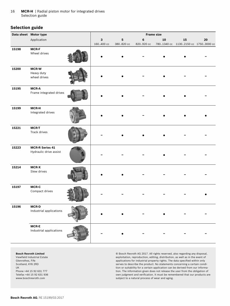
Selection guide Data sheet Motor type Frame size
Application 3160..400 cc
5380..820 cc
6820..920 cc
10780..1340 cc
151130..2150 cc
201750..3000 cc
15198 MCR-FWheel drives
● ● – ● ● –
15200 MCR-WHeavy duty wheel drives ● ● – ● – –
15195 MCR-AFrame integrated drives
● ● – ● ● –
15199 MCR-HIntegrated drives
● ● – ● ● ●
15221 MCR-TTrack drives
– ● ● ● – –
15223 MCR-R Series 41Hydraulic drive assist
– – – ● – –
15214 MCR-XSlew drives
● ● – – – –
15197 MCR-CCompact drives
– – – – – ●
15196 MCR-DIndustrial applications
● ● – ● – –
MCR-EIndustrial applications
– ● – – – –
Related Documents