RADAR AND NAVIGATIONAL AIDS

Radar introduction
Dec 02, 2015
it gives overall intro
Welcome message from author
This document is posted to help you gain knowledge. Please leave a comment to let me know what you think about it! Share it to your friends and learn new things together.
Transcript

RADAR AND NAVIGATIONAL AIDS

What is RADAR?
• The word radar is an abbreviation for RAdio Detection And Ranging
• Radar is an electromagnetic systems used for detection and location of objects such as aircraft, ship, vehicles, people, natural environment etc.
• Radar systems use modulated waveforms and directive antennas to transmit electromagnetic energy into a specific volume in space to search for targets.
• Objects (targets) within a search volume will reflect portions of this energy (radar returns or echoes) back to the radar.

Radar Principles • Transmitter generates and transmits electromagnetic wave (sine or pulse). One antenna can be used for both transmission and reception.
• The distance to the target (Range)- the time taken for the radar signal to travel to the target and back.
• Angular position, of the target - direction of arrival of the reflected wave front.
• Doppler effect – moving objects

Range- Distance from you and the target!
• The range of the object is found by the time the pulse takes to travel to and from the detected object
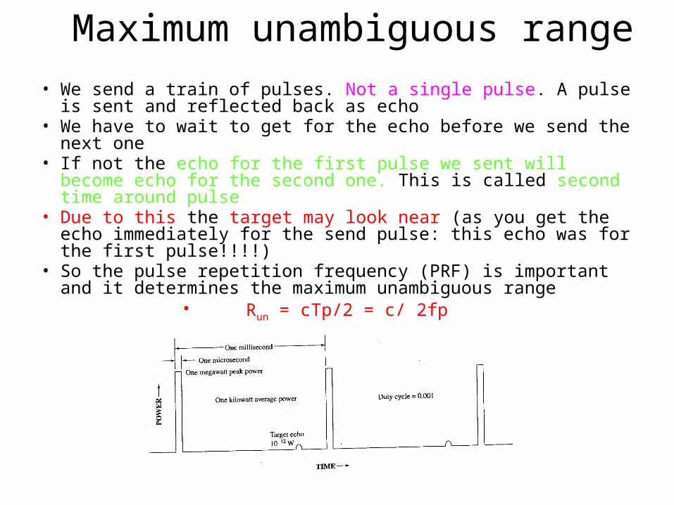
Maximum unambiguous range• We send a train of pulses. Not a single pulse. A pulse is sent and
reflected back as echo• We have to wait to get for the echo before we send the next one• If not the echo for the first pulse we sent will become echo for the
second one. This is called second time around pulse• Due to this the target may look near (as you get the echo
immediately for the send pulse: this echo was for the first pulse!!!!)
• So the pulse repetition frequency (PRF) is important and it determines the maximum unambiguous range
• Run = cTp/2 = c/ 2fp

TO INCREASE THE RANGE
• Transmitted power is increased• Gain of the antenna should be high• Large antenna for reception• The receiver should be sensitive to weak signals (should pick
them)• Range equation is an important derivation to calculate the
range.

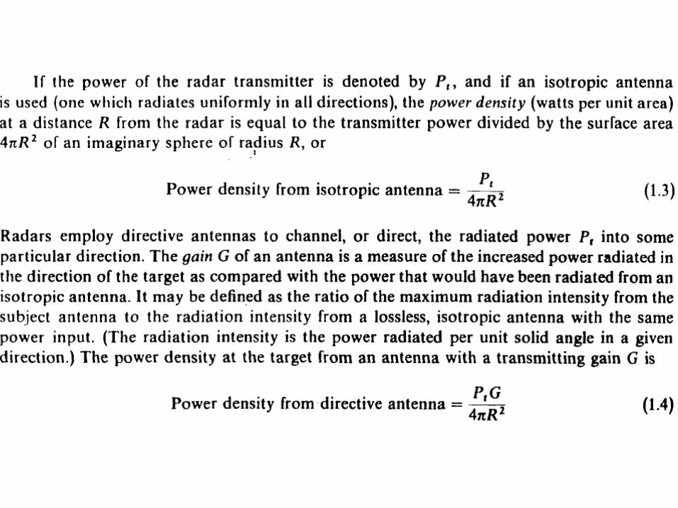
Radar Equation• The radar equation relates the range of a radar to the
characteristics of the transmitter, receiver, antenna, target, and environment.
• It is useful for determining the maximum distance from the radar to the target
• it can serve both as a tool for understanding radar operation and as a basis for radar design.
• However it cannot give the precise value. Why??– Statistical nature of noise and signal– Fluctuation & uncertainty of the target– Propagation effect of the wave– Losses
• Are affecting the calculation• We will consider each one separately.


RANGE PERFORMANCE
In practice the simple range equation does not predict range performance accurately. The actual range may be only half of that predicted .
Noise is in the system and it is random. So we have to have probability. If affects the detection. So we have to get SNR

Threshold detection• false alarm: if the threshold is set as low then the noise may be detected as target• Missed detection: If the threshold is set high then real target will be
missed. – However we use matched filter which will increase the SNR.– So we conclude that SNR is an important factor and more analysis
is needed.
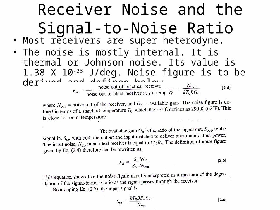
Receiver Noise and the Signal-to-Noise Ratio
• Most receivers are super heterodyne.• The noise is mostly internal. It is thermal or Johnson noise. Its
value is 1.38 X 10⁻²³ J/deg. Noise figure is to be derived and defined below

APPLICATIONSNavigational aid on ground and seaRadar altimeters (height measurement)Radar blind lander (aircraft landing during poor visibility)Airborne radar for satellite surveillance Planetary observationsPolice radars ( Highway safety)Remote sensing (weather monitoring)Air traffic control (ATC) and Aircraft safetyShip safetyNon-contact method of speed and distance in industry

MAIN TYPES OF RADAR
There are two main types of radar:
1)Primary Radar
Continuous wave Radar Pulse Radar
2)Secondary Radar

Pulse Radar

• The transmitter may be an oscillator, such as a magnetron• radar for the detection of aircraft at ranges of 100 or 200 nmi
might employ a peak power of the order of a megawatt, an average power of several kilowatts
• The duplexer might consist of two gas-discharge devices, one known as a TR (transmit-receive) and the other an ATR
(anti-transmit-receive).• The mixer and local oscillator (LO) convert the RF signal to an
intermediate frequency (IF).• Matched filter- to improve the signal to noise ratio.
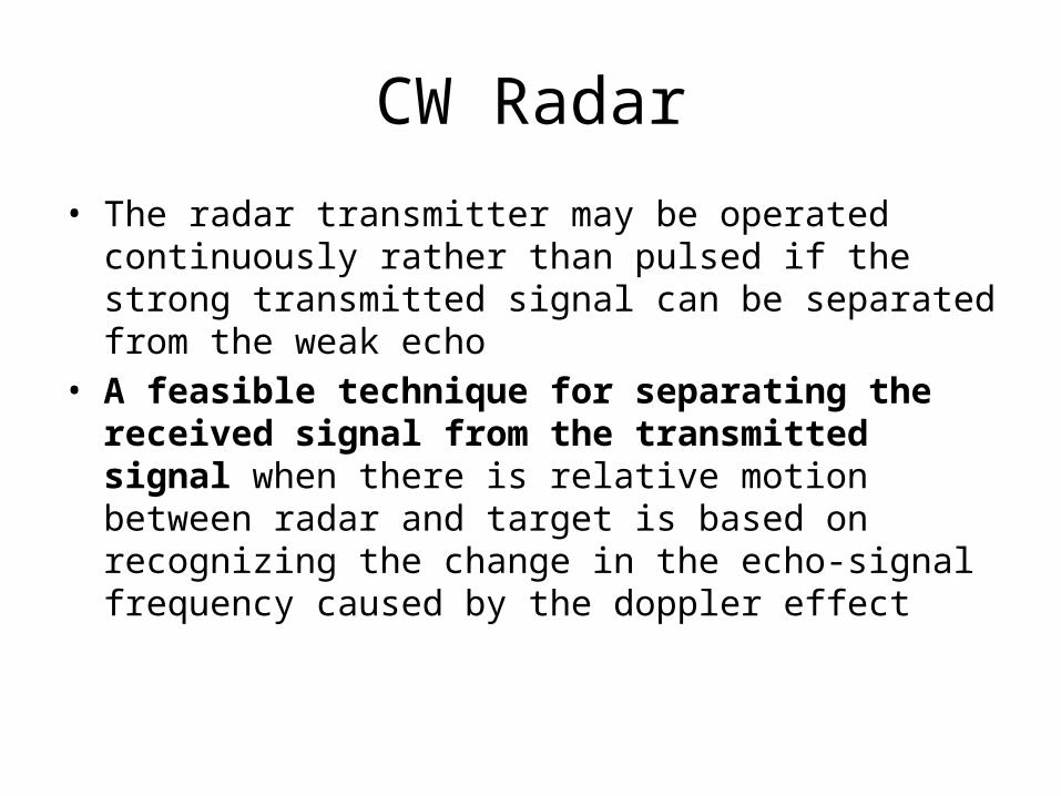
CW Radar
• The radar transmitter may be operated continuously rather than pulsed if the strong transmitted signal can be separated from the weak echo
• A feasible technique for separating the received signal from the transmitted signal when there is relative motion between radar and target is based on recognizing the change in the echo-signal frequency caused by the doppler effect

CW RADAR

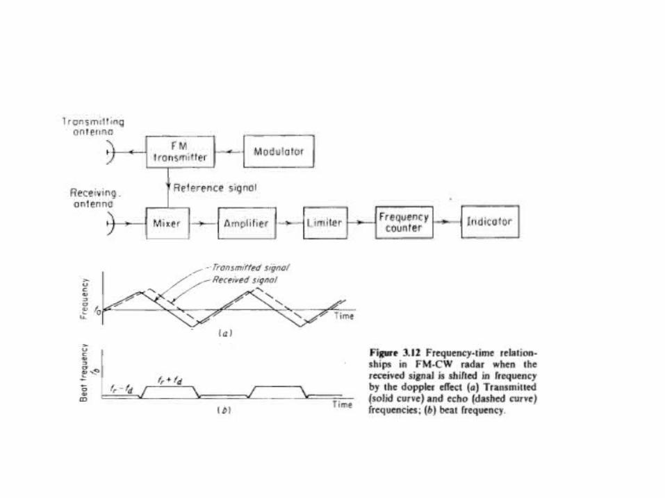
• If the target is in motion with a relative velocity vr to the Radar, then the received signal will be shifted by an amount of ‘±fd’.
• The purpose of Doppler amplifier is to eliminate the echos from stationary targets and to amplify the Doppler echo signal to a level where it can be used to operate an indicating device
• The low frequency cut-off must be high enough to reject the dc component caused by stationary targets. The upper cut-off frequency is selected to pass the higest Doppler frequency expected
• Intermediate receiver-flicker noise-

Isolation between transmitter and receiver:
• In principle, a single antenna may be employed since the necessary isolation between the transmitted and the received signals is achieved via separation in frequency as a result of the doppler effect
• A moderate amount of leakage entering the receiver along with the echo signal supplies the reference necessary for the detection of the doppler frequency shift
• (1) the maximum amount of power the receiver input circuitry can withstand before it is physically damaged or its sensitivity reduced
(burnout) • (2) the amount of transmitter noise due to hum, microphonics, stray
pick-up, and instability which enters the receiver from the transmitter

Disadvantages of CW Doppler Radar
1.When a single antenna is used for both transmission and reception, it is difficult to protect the receiver against the transmitter because in constant to pulse Radar, both are ON all the time. 2. These are able to detect only moving targets, as stationary targets will not cause a Doppler shift and the reflected signals will be filtered out. 3. CW Radars are not able to measure range, where range is normally measured by timing the delay between a pulse being sent and received but as CW Radars are always broadcasting; there is no delay to measure.

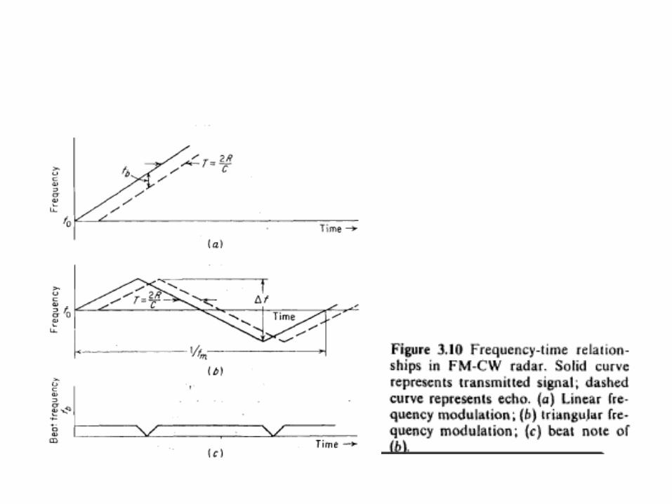
FM CW Radar
• CW radars have the disadvantage that they cannot measure distance, because it lacks the timing mark necessary to allow the system to time accurately the transmit and receive cycle and convert the measured round-trip-time into range. In order to correct for this problem, phase or frequency shifting methods can be used
• In the frequency shifting method, a signal that constantly changes in frequency around a fixed reference is used to detect stationary objects and to measure the rage. In such Frequency-Modulated Continuous Wave radars (FMCW), the frequency is generally changed in a linear fashion, so that there is an up-and-down or a sawtooth-like alternation in frequency

TRACKING RADAR
• Measures the coordinates and provides data to determine target path
• Tracking can be performed in range, angle and doppler• Classified into two types– Continuous tracking radar – Track-While-Scan radar
• Acquisition radar designates targets to the tracking radar

Error Signal generation
• The antenna beam in the continuous tracking radar is positioned in angle by a servomechanism actuated by an error signal. The various methods for generating the error signal may be classified as
1. Sequential lobing, 2. Conical scan, and
3.Simultaneous lobing or mononpulse.• The tracking radar must first find its target before it can
track. Some radars operate in a search, or acquisition, mode in order to find the target before switching to a tracking mode.

• Obviously, when the radar is used in its tracking mode, it has no knowledge of other potential targets.
• Also, if the antenna pattern is a narrow pencil beam and if the search volume is large, a relatively long time might be required to find the target.
• it called an acquisition radar.

SEQUENTIAL LODING• The antenna pattern commonly employed with tracking
radars is the symmetrical pencil beam in which the, elevation and azimuth beam widths are approximately equal.
• However, a simple pencil-beam antenna is not suitable for tracking radars unless means are provided for determining the magnitude and direction of the target's angular position with respect to some
• reference direction, usually the axis of the antenna. • The difference between the target position and the reference
direction is the angular error. • The tracking radar attempts to position the antenna to make
the angular error zero. When the angular error is zero, the target is located along the reference direction.

SEQUENTIAL LOBING• Two lobes are required to
track in each axis, each lobe must be sequentially switched four pulses are required
• The radar measures the returned signal levels
• The voltages in the two switched position should be equal

CONICAL SCAN
• A logical extension of the simultaneous lobing technique described in the previous section is to rotate continuously an offset antenna beam rather than discontinuously step the beam between four discrete positions. This is known as conical scan.
• The angle between the axis of rotation and the axis of antenna beam is called squint angle.

CONICAL SCAN
•The antenna is continuously rotated at an offset angle.
• Redirection of beam Rotating feed Nutating feed

CONICAL SCAN
B A

DISADVANTAGES
Sequential lobing1) Angle accuracy can be no better than the size of the antenna
beamwidth. 2) Variation in echo strength on a pulse-by-pulse basis changes the signal
level thereby reducing tracking accuracy3) The antenna gain is less than the peak gain in beam axis direction,
reducing maximum range that can be measured
Conical scan4) The antenna scan rate is limited by the scanning mechanism
(mechanical or electronic)5) Sensitive to target modulation6) Mechanical vibration and wear and tear due to rotating feed
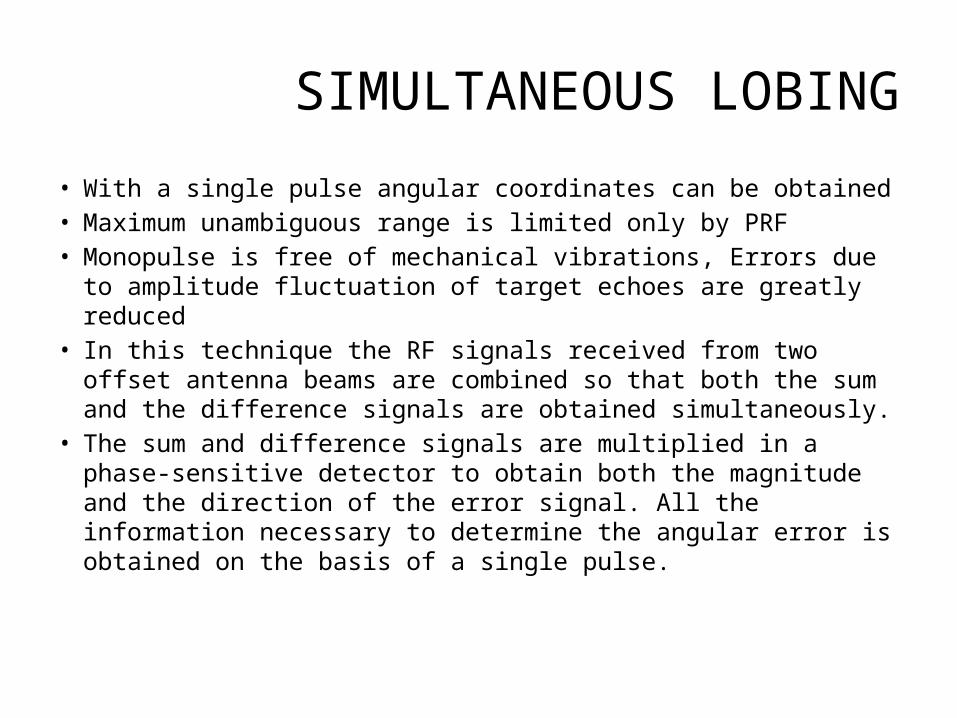
SIMULTANEOUS LOBING
• With a single pulse angular coordinates can be obtained• Maximum unambiguous range is limited only by PRF• Monopulse is free of mechanical vibrations, Errors due to
amplitude fluctuation of target echoes are greatly reduced• In this technique the RF signals received from two offset
antenna beams are combined so that both the sum and the difference signals are obtained simultaneously.
• The sum and difference signals are multiplied in a phase-sensitive detector to obtain both the magnitude and the direction of the error signal. All the information necessary to determine the angular error is obtained on the basis of a single pulse.
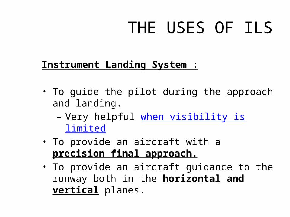
THE USES OF ILS
Instrument Landing System :
• To guide the pilot during the approach and landing.– Very helpful when visibility is limited
• To provide an aircraft with a precision final approach.• To provide an aircraft guidance to the runway both in
the horizontal and vertical planes.

Localizer
• Localizer is the horizontal antenna array located at the opposite end of the runway.
• Localizer operates in VHF band between 108 to 111.975 MHz
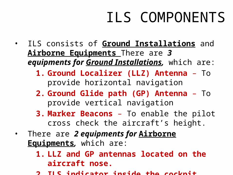
ILS COMPONENTS
• ILS consists of Ground Installations and Airborne Equipments There are 3 equipments for Ground Installations, which are:
1. Ground Localizer (LLZ) Antenna – To provide horizontal navigation
2. Ground Glide path (GP) Antenna – To provide vertical navigation
3. Marker Beacons – To enable the pilot cross check the aircraft’s height.
• There are 2 equipments for Airborne Equipments, which are:
1. LLZ and GP antennas located on the aircraft nose.2. ILS indicator inside the cockpit

Illustration

How does LOC work ?• Localizer transmit two signals which overlap at the
centre.• It operates in the VHF band: 108MHz to 117MHz • The left side has a 90 Hz modulation and the right has
a 150 Hz modulation.• The overlap area provides the on-track signal.• For example, if an aircraft approaching the runway
centre line from the right, it will receive more of the 150 Hz modulation than 90Hz modulation.
• Difference in Depth of Modulation will align the aircraft with the runway centre line.
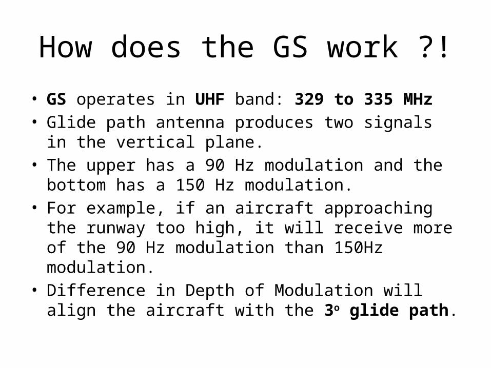
How does the GS work ?!
• GS operates in UHF band: 329 to 335 MHz• Glide path antenna produces two signals in the vertical
plane.• The upper has a 90 Hz modulation and the bottom has a
150 Hz modulation.• For example, if an aircraft approaching the runway too
high, it will receive more of the 90 Hz modulation than 150Hz modulation.
• Difference in Depth of Modulation will align the aircraft with the 3o glide path.

3. What do Marker Beacons do?They aid in indicating the distance of the aircraft from the runway.1. Outer Marker (OM)
The outer marker is normally located 7.2 to 10 km (4.5 to 6 mi) from the runway threshold. The cockpit indicator is a blue lamp that flashes in unison with the received audio code. The purpose of this beacon is to provide height, distance, and equipment functioning checks to aircraft on intermediate and final approach. On the aircraft, the signal is received by a 75 MHz marker receiver. The pilot hears a tone from the loudspeaker or headphones and a blue indicative bulb lights up.
2. Middle Marker(MM) The middle marker should be located so as to indicate, in low visibility conditions, the missed approach point, and the point that visual contact with the runway is imminent, ideally at a distance of approximately 3,500 ft (1,100 m) from the threshold. The cockpit indicator is an amber lamp that flashes in unison with the received audio code.

Airplane Approaching to the left of runway center line.
Observe the yellow NAV vertical pointer line tracking the runway center line and moving towards right.

Microwave Landing System
• MLS is an all-weather, precision landing system originally intended to replace or supplement ILS installations
• MLS has a number of operational advantages-i. wide selection of channels to avoid
interference with other nearby airports, ii. excellent performance in all weather, iii. wide vertical and horizontal ‘capture’ angles.

Related Documents


