1 Radar and Communication Co-existence: an Overview Le Zheng, Member, IEEE, Marco Lops, Fellow, IEEE, Yonina C. Eldar, Fellow, IEEE, and Xiaodong Wang, Fellow, IEEE Abstract—Increased amounts of bandwidth are required to guarantee both high-quality/high-rate wireless services (4G and 5G) and reliable sensing capabilities such as automotive radar, air traffic control, earth geophysical monitoring and security applications. Therefore, co-existence between radar and com- munication systems using overlapping bandwidths has been a primary investigation field in recent years. Various signal processing techniques such as interference mitigation, pre-coding or spatial separation, and waveform design allow both radar and communications to share the spectrum. This article reviews recent work on co-existence between radar and communication systems, including signal models, waveform design and signal processing techniques. Our goal is to survey contributions in this area in order to provide a primary starting point for new researchers interested in these problems. Index Terms—Radar/communication co-existence, spectrum sharing. I. I NTRODUCTION The use of radar has been widened to numerous civilian applications including traffic control, remote sensing, car cruise control and collision avoidance. On a parallel track, the quest for ever increasing rates in wireless communications has pushed the carrier frequencies towards bands traditionally assigned to radar systems. This, along with the need to limit electromagnetic pollution, results in the scenario of co-existing radar and communication systems [1], [2]. Emerging technolo- gies in this field rely on concepts such as passive sensing, waveform diversity, co-design and the so called “bio-inspired” strategies, wherein each part of a given architecture is seen as a sub-system whose design choices must be negotiated with the other constituent subsystems. To this last philosophy belong the class of cognitive systems, which are in turn intimately linked to the concept of Bayesian learning as a means to facilitate and sometimes enable individual decision-making [1], [3], [4]. The last few years have seen the growth of vibrant industrial and academic interest towards the convergence of sensing and communication functions. This has been affirmed by the announcement of the Shared Spectrum Access for Radar and Comm (SSPARC) program by the Defense Advanced Le Zheng is with Electronics & Safety, Aptiv, Agoura Hills, CA, 91301, e-mail: [email protected]. Marco Lops is with the Dipartimento di Ingegneria Elettrica e delle Tecnologie dell’Informazione (DIETI) University of Naples “Federico II” Via Claudio 21, 80125 Naples (Italy), e-mail: [email protected]. Yonina C. Eldar is with the Department of Electrical Engineering, Technion, Israel Institute of Technology, Haifa 32000, Israel. Xiaodong Wang is with Electrical Engineering Department, Columbia University, New York, USA, 10027, e-mail: [email protected]. Research Projects Agency (DARPA) [5] and the demands of sensing and communication for self-driving cars [6]. As a result, a number of studies have been conducted, based on a variety of scenarios, degrees of cooperation between the coexisting systems, and design strategies. The goal of this paper is to review existing results in this context and define a taxonomy of the different philosophies proposed so far. Three major architectures for co-existence have been henceforth defined: (a) Co-existence in spectral overlap; (b) Co-existence via cognition; (c) Functional co-existence. Category (a) includes architectures wherein both radar and communication systems are equipped with active transmitters using the same frequency spectrum. Here, the major problem is to eliminate or mitigate mutual interference while guaranteeing satisfactory performance for both functions. Different degrees of cooperation between the active systems have been so far accounted for. Absolute lack of cooperation is assumed. For example, in [7], [8] where the inherent resilience of properly designed coherent Multiple-Input Multiple-Output (MIMO) radars to the interference is exploited and attention is paid to the performance of the radar system only. A similar “radar-centric” philosophy is adopted in [9], [10], wherein co- existing communication users are safeguarded by limiting the amount of interference produced by the radar on given sub- bandwidths. Symmetrically, uncooperative “communication- centric” approaches have been suggested in a number of more recent studies, wherein countermeasures against the radar- induced interference are taken either at the communication receiver [11] or, in the presence of some prior information, directly at the transmitter [12], [13]. Cooperation between the active systems, possibly operating in full spectral overlap, in order to negotiate the respec- tive transmit policies and adjust the corresponding detec- tion/demodulation strategies is the idea underlying co-design, first introduced in [3], and further developed in [14]–[19]. In this approach, which we define holistic, the co-existing systems are seen as constituent parts of a whole, so that the degrees of freedom under the designer’s control are both the waveform(s) transmitted by the sensing systems and the code- book(s) employed by the communication systems. These are jointly optimized so as to guarantee that both the communi- cation and the radar performance are satisfactory. Co-design allows taking into account in the transceiver design effects such as the reverberation produced by the radar, due to clutter arXiv:1902.08676v1 [eess.SP] 22 Feb 2019

Welcome message from author
This document is posted to help you gain knowledge. Please leave a comment to let me know what you think about it! Share it to your friends and learn new things together.
Transcript

1
Radar and Communication Co-existence: anOverview
Le Zheng, Member, IEEE, Marco Lops, Fellow, IEEE, Yonina C. Eldar, Fellow, IEEE, and Xiaodong Wang,Fellow, IEEE
Abstract—Increased amounts of bandwidth are required toguarantee both high-quality/high-rate wireless services (4G and5G) and reliable sensing capabilities such as automotive radar,air traffic control, earth geophysical monitoring and securityapplications. Therefore, co-existence between radar and com-munication systems using overlapping bandwidths has beena primary investigation field in recent years. Various signalprocessing techniques such as interference mitigation, pre-codingor spatial separation, and waveform design allow both radarand communications to share the spectrum. This article reviewsrecent work on co-existence between radar and communicationsystems, including signal models, waveform design and signalprocessing techniques. Our goal is to survey contributions inthis area in order to provide a primary starting point for newresearchers interested in these problems.
Index Terms—Radar/communication co-existence, spectrumsharing.
I. INTRODUCTION
The use of radar has been widened to numerous civilianapplications including traffic control, remote sensing, carcruise control and collision avoidance. On a parallel track,the quest for ever increasing rates in wireless communicationshas pushed the carrier frequencies towards bands traditionallyassigned to radar systems. This, along with the need to limitelectromagnetic pollution, results in the scenario of co-existingradar and communication systems [1], [2]. Emerging technolo-gies in this field rely on concepts such as passive sensing,waveform diversity, co-design and the so called “bio-inspired”strategies, wherein each part of a given architecture is seen as asub-system whose design choices must be negotiated with theother constituent subsystems. To this last philosophy belongthe class of cognitive systems, which are in turn intimatelylinked to the concept of Bayesian learning as a means tofacilitate and sometimes enable individual decision-making[1], [3], [4].
The last few years have seen the growth of vibrant industrialand academic interest towards the convergence of sensingand communication functions. This has been affirmed bythe announcement of the Shared Spectrum Access for Radarand Comm (SSPARC) program by the Defense Advanced
Le Zheng is with Electronics & Safety, Aptiv, Agoura Hills, CA, 91301,e-mail: [email protected].
Marco Lops is with the Dipartimento di Ingegneria Elettrica e delleTecnologie dell’Informazione (DIETI) University of Naples “Federico II” ViaClaudio 21, 80125 Naples (Italy), e-mail: [email protected].
Yonina C. Eldar is with the Department of Electrical Engineering, Technion,Israel Institute of Technology, Haifa 32000, Israel.
Xiaodong Wang is with Electrical Engineering Department, ColumbiaUniversity, New York, USA, 10027, e-mail: [email protected].
Research Projects Agency (DARPA) [5] and the demands ofsensing and communication for self-driving cars [6]. As aresult, a number of studies have been conducted, based ona variety of scenarios, degrees of cooperation between thecoexisting systems, and design strategies.
The goal of this paper is to review existing results in thiscontext and define a taxonomy of the different philosophiesproposed so far. Three major architectures for co-existencehave been henceforth defined:
(a) Co-existence in spectral overlap;(b) Co-existence via cognition;(c) Functional co-existence.
Category (a) includes architectures wherein both radar andcommunication systems are equipped with active transmittersusing the same frequency spectrum. Here, the major problem isto eliminate or mitigate mutual interference while guaranteeingsatisfactory performance for both functions. Different degreesof cooperation between the active systems have been sofar accounted for. Absolute lack of cooperation is assumed.For example, in [7], [8] where the inherent resilience ofproperly designed coherent Multiple-Input Multiple-Output(MIMO) radars to the interference is exploited and attentionis paid to the performance of the radar system only. A similar“radar-centric” philosophy is adopted in [9], [10], wherein co-existing communication users are safeguarded by limiting theamount of interference produced by the radar on given sub-bandwidths. Symmetrically, uncooperative “communication-centric” approaches have been suggested in a number of morerecent studies, wherein countermeasures against the radar-induced interference are taken either at the communicationreceiver [11] or, in the presence of some prior information,directly at the transmitter [12], [13].
Cooperation between the active systems, possibly operatingin full spectral overlap, in order to negotiate the respec-tive transmit policies and adjust the corresponding detec-tion/demodulation strategies is the idea underlying co-design,first introduced in [3], and further developed in [14]–[19].In this approach, which we define holistic, the co-existingsystems are seen as constituent parts of a whole, so that thedegrees of freedom under the designer’s control are both thewaveform(s) transmitted by the sensing systems and the code-book(s) employed by the communication systems. These arejointly optimized so as to guarantee that both the communi-cation and the radar performance are satisfactory. Co-designallows taking into account in the transceiver design effectssuch as the reverberation produced by the radar, due to clutter
arX
iv:1
902.
0867
6v1
[ee
ss.S
P] 2
2 Fe
b 20
19
2
or targets moving in close proximity to the communicationreceiver, range ambiguities and (random) Doppler frequencies.It is important to underline that these schemes are heavilyknowledge-based and rely on information exchange betweenthe constituent systems: this presupposes, on one hand, thepresence of a “fusion center” accessible to both systems, and,on the other, the accessibility of a common database, whereinthe basic channel parameters are made available.
In dynamic scenarios co-design may greatly benefit fromcognitive paradigms. Here channel state is learned throughsuitable algorithms, which is conducive to the philosophyof co-existence via channel sensing put forth in [4] and,more generally, to category (b) of the classification above. Infact, category (b) comprises systems wherein spectral overlapbetween the communication and radar transmitters is avoidedthrough cognition, so that the corresponding channels areinterference-free. Starting from the idea, proposed in [14] andborrowed from cognitive radio networks, of using pilot signalsto estimate the channels and share the channel informationbetween the subsystems, new approaches have been recentlyproposed wherein the radar and/or the communication systemare able to “learn” the environment without transmitting pilotsor avoiding the need for coordination [20]–[23]. In [4], forexample, the SpeCX system combines sub-Nyquist multi-bandsensing with sub-Nyquist radar [24] so as to enable the radarto sense the communication channel at very low rates.
Category (c) comprises architectures wherein there is onlyone active transmitter, whereby co-existence is functional, butno interference is produced and no real resource negotiationtakes place. Dual Function Radar Communication (DFRC)systems rely on combining radar and communication transmit-ters in the same hardware platform, which should be designedso as to guarantee the performances of both systems: theinformation is embedded [25]–[28] in the radar signal, and aMIMO radar transmitter uses a combination of beam-formingand waveform diversity in order to direct information bitstowards multiple communication receivers, without affectingthe performance of the sensing function, while guaranteeingsatisfactory Bit Error Rate (BER) performance. Opportunisticsensing systems, instead, consist of a receiver co-located withthe communication transmitter and a dedicated software chainaimed at processing the received signal. The receiver canavail itself of some side information, such as timing andtransmitted data. This architecture has been proposed andtheoretically assessed with reference to the 802.11ad formatused in conjuction with a sensing system in an automotiveenvironment [29], [30]. Passive radar systems also can bethought of as belonging to category (c) since they exploit othertransmissions (communications, broadcast, or radionavigation)rather than having their own dedicated radar transmitter [1],[31].
The article structure reflects the above categorization: inSec. II we review systems in spectral overlap, by consideringthe cases of uncoordinated and coordinated transmission. Sec.III is devoted to cognition-based systems and Sec. IV focuseson functional duality. Concluding remarks and suggestions forfuture investigations are presented in Sec. V.
II. CO-EXISTENCE IN SPECTRAL OVERLAP
A. System Model
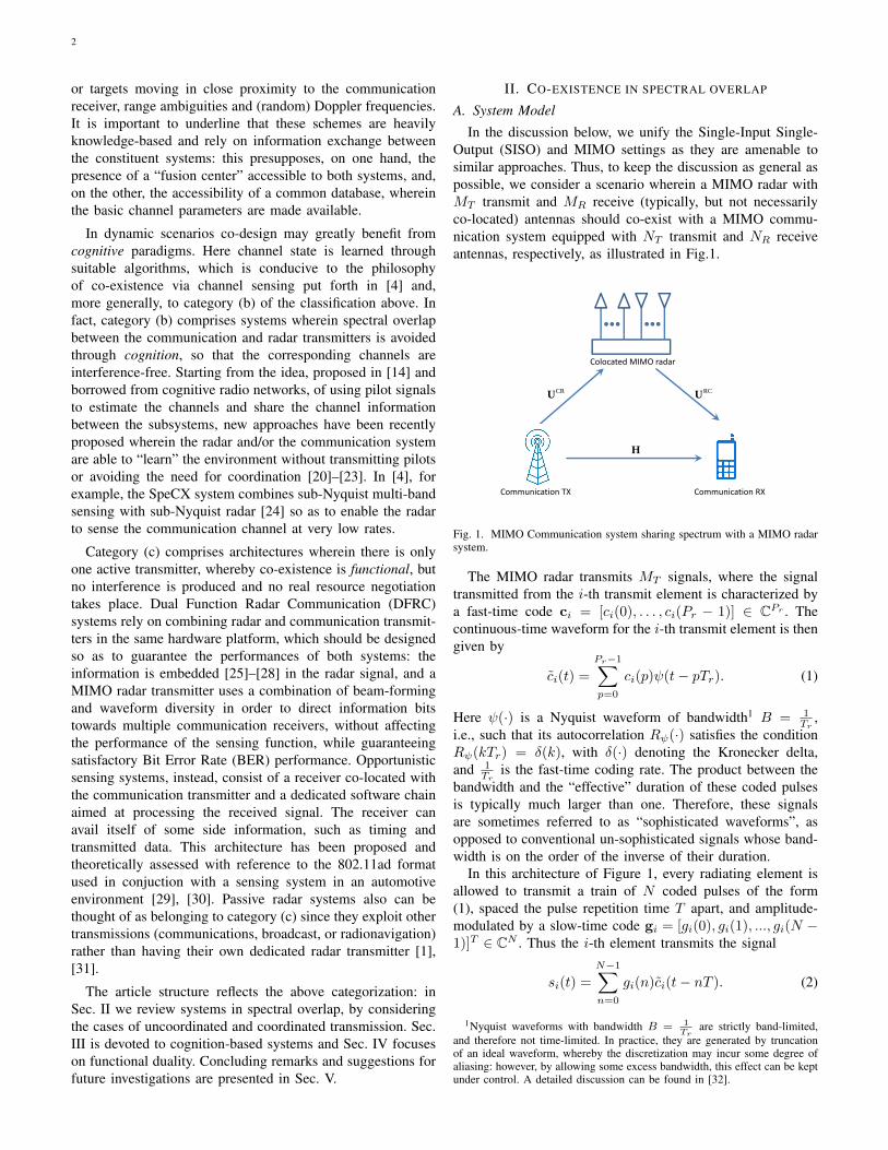
In the discussion below, we unify the Single-Input Single-Output (SISO) and MIMO settings as they are amenable tosimilar approaches. Thus, to keep the discussion as general aspossible, we consider a scenario wherein a MIMO radar withMT transmit and MR receive (typically, but not necessarilyco-located) antennas should co-exist with a MIMO commu-nication system equipped with NT transmit and NR receiveantennas, respectively, as illustrated in Fig.1.
Colocated MIMO radar
CRU RCU
H
Communication TX Communication RX
Fig. 1. MIMO Communication system sharing spectrum with a MIMO radarsystem.
The MIMO radar transmits MT signals, where the signaltransmitted from the i-th transmit element is characterized bya fast-time code ci = [ci(0), . . . , ci(Pr − 1)] ∈ CPr . Thecontinuous-time waveform for the i-th transmit element is thengiven by
ci(t) =
Pr−1∑p=0
ci(p)ψ(t− pTr). (1)
Here ψ(·) is a Nyquist waveform of bandwidth1 B = 1Tr
,i.e., such that its autocorrelation Rψ(·) satisfies the conditionRψ(kTr) = δ(k), with δ(·) denoting the Kronecker delta,and 1
Tris the fast-time coding rate. The product between the
bandwidth and the “effective” duration of these coded pulsesis typically much larger than one. Therefore, these signalsare sometimes referred to as “sophisticated waveforms”, asopposed to conventional un-sophisticated signals whose band-width is on the order of the inverse of their duration.
In this architecture of Figure 1, every radiating element isallowed to transmit a train of N coded pulses of the form(1), spaced the pulse repetition time T apart, and amplitude-modulated by a slow-time code gi = [gi(0), gi(1), ..., gi(N −1)]T ∈ CN . Thus the i-th element transmits the signal
si(t) =
N−1∑n=0
gi(n)ci(t− nT ). (2)
1Nyquist waveforms with bandwidth B = 1Tr
are strictly band-limited,and therefore not time-limited. In practice, they are generated by truncationof an ideal waveform, whereby the discretization may incur some degree ofaliasing: however, by allowing some excess bandwidth, this effect can be keptunder control. A detailed discussion can be found in [32].
3
Some special cases of the radar signal model (2) are asfollows:
1) A single-antenna transmitter using a single signalwith fast-time code c = [c(0), . . . , c(Pr − 1)]T ,corresponding to N = MT = 1.
2) A single-antenna transmitter using an amplitude-modulated train of pulses, corresponding to MT = 1,Pr = 1. The train is uniquely determined by theslow-time code g = [g(0), . . . , g(N − 1)]T ∈ CN .The usual pulsed-radar corresponds to an all-oneslow-time code.
3) A multi-antenna transmitter wherein each antennatransmits a single sophisticated signal. As a conse-quence, N = 1, si(t) = ci(t) and the Pr × MT
space-time code matrix C = [c1, . . . , cMT] is the
degree of freedom to be employed at the transmitterside [33].
4) A multi-antenna transmitter wherein each an-tenna transmits a train of unsophisticated signals,amplitude-modulated by the slow-time code. In thiscase, Pr = 1 and the N×MT space-time code matrixG = [g1, . . . ,gMT
] is the degree of freedom at thetransmitter side [17].
Radars use radio waves to determine the range, angle, orvelocity of objects. The operation of a typical MIMO radarreceive chain is summarized in the box of Page 4. The radarrange resolution is dictated, for a given Signal-to-Noise Ratio(SNR), by the transmit bandwidth, i.e., 1/Tr in (1). Thevelocity resolution is determined by the duration of coherentintegration, i.e., NT in (2). In situations 1) and 3) no Dopplerprocessing is undertaken, mainly due to the fact that typicalsingle-pulse durations are too short to allow measuring theDoppler shift induced by targets in moderate radial motion.In settings 2) and 4) moving objects generate steering vectorsand Doppler shifts up to 1
T can be unambiguously measured.Likewise, pulse trains with Pulse Repetition Time (PRT)T generate range ambiguities whereby scatterers located atdistances corresponding to delays which are integer multiplesof T contribute to the same range cell.
The signal model for the communication system is simplerin that we just have to distinguish between the case of singleand multiple transmit antennas. In particular, we assume thatthe communication system operates on the same frequencyband as the radar, occupying a fraction B
L of its dedicatedbandwidth. Setting Tc = L/B, the signal radiated by the i-thtransmit element is written as
xi(t) =
∞∑p=−∞
vi(p)ψL(t− pTc), (3)
where vi(p) is the data sequence to be transmitted, and ψL(·)satisfies the Nyquist criterion with respect to Tc = LTr.The situation of full spectral overlap corresponds to L = 1.We note that there may be a multiplicity of narrow-bandcommunication systems, each occupying a fraction of the radarbandwidth.
Assume that the radar and the communication receivers areequipped with MR and NR receive antennas, respectively. The
signal at the j-th antenna of the radar receiver (RX) can becast in the form
rj(t) =
MT∑i=1
ai,jsi(t− τi,j) +
NT∑i=1
(uCRi,j ∗ xi)(t)
+
MT∑i=1
(aIi,j ∗ si)(t) + nR,j(t), (4)
where ai,j is the target complex backscattering coefficient,including the path loss and the phase shift due to the targetangle and position with respect to the transmit and receiveantennas; uCR
i,j (t) is the response of the channel from thecommunication Transmitter (TX) to the radar RX; τi,j is thedelay of the target from the i-th TX to the j-th RX; aI
i,j(t) isthe response of the clutters; ∗ is the convolution operation; andnR,j(t) denotes the noise at the j-th RX antenna. Likewise,the signal received at the j-th antenna of the communicationRX is given by
yj(t) =
NT∑i=1
(hi,j ∗ xi)(t) +
MT∑i=1
(uRCi,j ∗ si)(t) + nC,j(t), (5)
where hi,j(t) is the channel response from the i-th com-munication TX to the j-th communication RX; uRC
i,j (t) isthe response of the interfering channel from radar TX tocommunication RX; and nC,j(t) denotes the noise of the j-thcommunication RX antenna.
In (4), the transmitted signal si(t) is known and uCRi,j (t) can
be estimated via pilot training. On the other hand, xi(t) andaIi,j(t) are unknown at the radar RX. The radar needs to detect
the presence of the target, i.e., ai,j = 0 for H0 and ai,j 6= 0for H1, and estimate the paramters τi,j and aI
i,j(t). For thecommunication system given by (5), hi,j(t) can be estimatedvia pilot training. In coordinated architectures, where the radartransmits pilots and communicates with the communicationRX, uRC
i,j and si(t) are known at the communication RX, whilein uncoordinated scenarios uRC
i,j and si(t) are both unknown.Based on the models (4) and (5), different co-existence
scenarios can be analyzed. Sec. II-B discusses a radar-centricapproach wherein a single-antenna radar transmits a singlesophisticated signal with fast-time code, i.e. situation 1).Sec. II-C reviews some communication-centric approaches,assuming different degrees of prior knowledge as to the radarinterference (i.e., scenarios 2) and 3) ). Sec. II-D focuses oncoordinated design of the radar waveform(s) and the commu-nication code-books, assuming the most general scenario (i.e.,scenarios 3) and 4) ) of multiple transmit and receive antennasfor both systems, with either slow-time or fast-time coding.
B. Uncoordinated design: radar centric
We begin by discussing a “radar-centric” approach in whichthe radar function is considered primary, while unlicensedusers are allowed to transmit in partial spectral overlap onthe same bandwidth. Following [9], [10], we assume NIinterferers of the form (3). Their presence is acknowledgedby limiting the amount of interference the radar produces onthe shared bandwidths. The focus is on the design of the radarsystem, assumed to employ a single coded pulse according to
4
Classic collocated MIMO radar processing traditionally includes the following stages:1) Sampling: At each radar RX 1 ≤ j ≤ MR, the signal rj(t) is projected onto the orthonormal system {ψ(t −
mTr)}Pr−1m=0 and sampled at its Nyquist rate B = 1
Tr, creating the samples rj(m), 0 ≤ m ≤ Pr − 1.
2) Matched filter: The sampled signal is convolved with the transmitted radar codes ci, 1 ≤ i ≤ MT . The timeresolution attained in this step is 1/B.
3) Beamforming: The correlations between the observation vectors from the previous step and the steering vectorscorresponding to each azimuth on the grid defined by the array aperture are computed.
4) Doppler detection: The correlations between the resulting vectors and Doppler vectors, with Doppler frequencieslying on the grid defined by the number of pulses, are computed. The Doppler resolution is 1/NT .
5) Peak detection: A heuristic detection process, in which knowledge of the number of targets, targets’ powers, clutterlocation, and so on, may help in discovering targets’ positions. For example, if we know there are κ targets, thenwe can choose the κ-strongest points in the map. Alternatively, constant false alarm (FA) rate detectors determinea power threshold, above which a peak is considered to originate from a target so that a required probability ofFA is achieved.
situation 1) of the previous section, designed so as to guaranteethe maximum possible Signal to Interference-plus-Noise Ratio(SINR) at the radar RX.
Assume that the radar RX is equipped with a single antennaand the interference is dominated by the direct path betweenthe radar and the communication: the subscript j can thusbe removed from the variables in (4). Thus, rj(t) becomesr(t), and uCR
i (t) = δ(t − τRCi ), with τRC
i dictated by thedistance between the i-th communication TX and the radarRX. Such a model holds for narrowband systems where the flatfading assumption is valid [14], and can be extended to moresophisticated situations by using different forms of channelresponses [34]. For simplicity, we assume there is only onetarget and let the target delay be τ = 0.
Plugging (2) into (4) and projecting the equation onto theorthonormal system {ψ(t−mTr)}Pr−1
m=0 leads to
r(m) = 〈r(t), ψ(t−mTr)〉
= 〈aPr−1∑p=0
ci(p)ψ(t− pTr), ψ(t−mTr)〉
+
NT∑k=1
uk 〈x(t− τCRk ), ψ(t−mTr)〉︸ ︷︷ ︸xk(m)
+ 〈MT∑i=1
(aIi ∗ si)(t), ψ(t−mTr)〉︸ ︷︷ ︸
nI(m)
+ 〈nR(t), ψ(t−mTr)〉︸ ︷︷ ︸nR(m)
(6)
with a the target complex backscattering coefficient, includingthe path loss, and uk the coefficient of the interfering channelfor user k. Denoting r = [r(0), r(1), ..., r(Pr − 1)]T , we have
r = ac +
NI∑k=1
ukxk + nI + nR ∈ CPr , (7)
with xk = [xk(0), xk(1), ..., xk(Pr − 1)]T the k-thcommunication user occupying the bandwidth, nI =[nI(0), nI(1), ..., nI(Pr − 1)]T ∈ CPr the clutter, and nR =[nR(0), nR(1), ..., nR(Pr − 1)]T ∈ CPr the noise term.
Equation (7) describes the model for the signal in the radarRX. Next, we discuss the interference from the radar to thecommunication users, i.e., the second term in (5). As to thecommunication users coexisting with the radar of interest, wesuppose that each of them is operating over a frequency band[fk1 , f
k2 ], where fk1 and fk2 denote the lower and upper normal-
ized frequencies for the k-th system, respectively. Following(2) and (3) in [9], the interfering energy produced on the k-thcommunication user is given by cHRkc where
Rk(m,n) =
{fk2 − fk1 , if m = nej2πf
k2 (m−n)−ej2πf
k1 (m−n)
j2π(m−n) , if m 6= n(8)
(m,n) ∈ {1, 2, ..., Pr}2 .
The covariance matrix M of the exogenous interference, i.e. ofthe signal-independent component of the overall interference∑NIk=1 ukxk + nR, is assumed to be known or perfectly
estimated.The objective thus becomes to design the radar code c so as
to maximize the SINR at the radar RX while ensuring that theinterference produced on the co-existing communication usersis smaller than a constrained value. Additional constraints tobe enforced are an energy constraint on the radar code c,and its “closeness” to some reference code c0 with prescribedcorrelation properties [9], [10]: the latter is also referred to asa “similarity constraint”. The design then reduces to solvingthe following constrained maximization problem:
maxc∈CN×1
SINR = a2cHM−1c (9)
s.t.
NR∑k=1
ωkcHRkc ≤ EI,
(1− η)ρ ≤ cHc ≤ ρ,‖c− c0‖2 ≤ ε,

5
In the above equation, the terms cHRkc represent the inter-ference produced onto the k communication receiver, k =1, 2, . . . , NR, EI the maximum interference that can be tol-erated by the coexisting communication networks, ωk ≥ 0for k = 1, 2, ..., NR are weights that can be assigned to thecoexisting wireless users based, for instance, on their distancefrom the radar and their tactical importance, 0 ≤ η ≤ 1 isa design parameter which introduces some tolerance on thenominal interference level, ρ is the transmit energy of the radar.With relaxation, the optimization problem (9) can be trans-formed into a convex optimization amenable to Semi-DefiniteProgramming (SDP), which entails polynomial computationalcomplexity [10].
The scenario leading to problem (9) holds true only whenthe clutter is either absent or has rank one covariance matrix,i.e. is modeled as a specular image of the transmitted signalreflected towards the receiver by a point-like scatterer. If,conversely, more complex channel models are considered,and the clutter covariance has rank larger than one (i.e., thepoint-like model does not carry over to reverberation), thenconstrained maximization of the SINR results in a fractionalnon-convex problem [16].
C. Uncoordinated design: communication centric
The approach of optimizing radar waveforms, althoughtheoretically well established, is not always applicable, mainlydue to the fact that governmental and military agencies areunwilling to make major changes in their radar deployments,which may impose huge costs. Thus, coexisting communica-tion systems must be equipped with proper counter-measuresto guarantee required Quality of Service (QoS) when the radarsystem(s) do not modify their transmission policy. Attentionis thus shifted back to the communication transceiver, whichexplains the name “communication-centric” design. The ap-proaches so far available in the literature focus either on thereceiver [11], when prior information on the radar signals isnot available, or on the transmitter [13], when the structure ofthe radar transmitted waveform is known.
Assume first the scenario considered in [11], wherein amultiplicity of radars may be potentially active in full spectraloverlap with a communication system. Each radar is allowedto transmit a sophisticated waveform, but no prior knowledgeas to the number of active systems, their distance from thecommunication receiver or the channel gains is available. Thescenario is thus akin to the one outlined in situation 3) ofthe list of Sec. II-A, wherein MT now plays the role of themaximum number of potentially active emitters. The antennasof such a “multiple input” system are widely spaced, so thatthe delays with which their signals arrive at the communicationreceiver are all different and unknown.
As to the communication signal, the scenario assumed in[11] is fairly general. The transmitted symbols are assumedto undergo suitable pre-coding, where the choice of the pre-coding matrix dictates the type of system, ranging from Code-Division Multiple Access (CDMA) to Orthogonal Frequency-Division Multiplexing (OFDM). In particular, suppose thecommunication and radar systems have the same bandwidth,
i.e., L = 1, Tc = Tr and ψL(t) = ψ(t). The signal transmittedby the communication system in the interval [0, PrTr] isassumed to have the form
x(t) =
Pr−1∑p=0
v(p)ψ(t− pTr).
In the above equation, v = [v(0), . . . , v(Pr − 1)]T ∈CPr is tied to a generic P -dimensional data vector b0 =[b0(0), . . . , b0(P − 1)]T to be transmitted as v = Ab0, withA ∈ CPr×P a suitable matrix. Relevant special cases of theabove model are the OFDM transmission format, whereinPr = P and A takes on the form of an Inverse DiscreteFourier Transform (IDFT) matrix, and a CDMA system withP active users, wherein A contains the users’ signatures [11].Here, in order to keep the discussion simple, we confine ourattention to the case of direct transmission of the constellationpoints in full spectral overlap, so that P = Pr, b0 = b ∈ CPr ,A = IPr (IPr denotes the identity matrix of order Pr).
Suppose a single antenna communication RX, and single-tapmodel for both communication and interference channels. It isalso assumed that the (typically high-power) radar transmitteris not saturating the front-end of the communication receiver.The communication signal in (5) can thus be re-written as
y(t) = h
Pr−1∑p=0
b(p)ψ(t− pTr)
+
MT∑m=1
Pr−1∑p=0
umcm(p)ψ(t− pTr − τm) + nC(t). (10)
Here a flat-fading channel is assumed for the communicationnetwork where h is the channel coefficient, τm and umdenote the (unknown) delay and complex coupling coefficientfor the m-th radar, respectively. When um = 0, the m−thtransmitter is idle. We also assume that in each frame Prsymbols are transmitted and that the frame sychronizationbetween the radar and communication is guaranteed, i.e., thecommunication system is made aware of the beginning of theradar train pulse. This is a low-rate information, which can beshared once and for all, and regularly updated to account forpossible timing drifts.
The communication RX has to accomplish jointly the twotasks of interference estimation/removal and data demodu-lation. For interference removal, we need to estimate τmand umcm(p) so as to substract the second term from (10).Obviously, data demodulation and interference estimation areinherently coupled. In [35], an iterative procedure is proposedfor joint data demodulation and interference estimation, anda direct demodulation function b(0) = Ψ({y(t)}0≤t≤PrTr ) isused as the initial step. In a general uncoordinated scenario, thecommunication receiver may not know the exact form of theinterfering radar signals, but only rely on a coarse informationof the family they belong to. A viable means to account for thisuncertainty is to assume that cm lives in a low-dimensionalsubspace of CPr , spanned by the columns of a known Pr×Kmatrix Φ = [φ0,φ1, ...,φPr−1]T ∈ CPr×K with K � Pr,i.e., cm = Φαm for some unknown αm ∈ CK , tied to the
6
8 10 12 14 16 18 2010
−3
10−2
10−1
100
SNR (dB)
SE
R
Iteration 0CS−L1CS−ANKnown radar delay
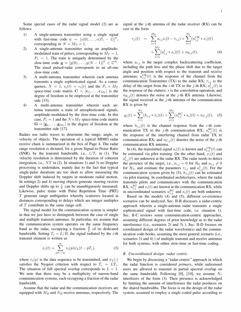
Fig. 2. Comparison of the algorithm SERs. Figure is taken from [11].
corresponding minimal and maximum distances of all of thepotential radar transmitters from the receiver.
Following [11], the signal z(`)(t) = y(t) −h∑Pr−1p=0 b(`)(p)ψ(t − pTr) contains the superposition of the
residual communication signal (due to demodulation errors),the residual radar interference and noise. To understandthe joint interference removal and symbol demodulationalgorithm proposed in [11], let us refer to the first iteration:
z(1)(t) = h
Pr−1∑p=0
(b(p)− b(0)(p)
)︸ ︷︷ ︸
β(0)(p)
ψ(t− pTr)
+
MT∑m=1
Pr−1∑p=0
φTmumαmψ(t− pTr − τm)︸ ︷︷ ︸X(t)
+nC(t),(11)
where τm for m = 1, 2, ...,MT are the desired unknowndelays: in the above equation, the quantities φm and h areknown, while the objects of interest to be estimated are τm,β(0)(p) and umαm.
Define β(`) = [β(`)(0), β(`)(1), ..., β(`)(Pr − 1)]T . Noticethat building up iterations may rely on two types of sparsity, inthat a) X(t) in (11) is a combination of at most MT compo-nents with unknown modulation umαm, and MT � Pr, andb) ‖β(`)‖0 has to be as small as possible. The problem can besolved by using the recently developed mathematical theoryof continuous sparse recovery for super-resolution and in par-ticular of Atomic-Norm (AN) minimization techniques [11].Figure 2 illustrates the achievable results in terms of SymbolError Rate (SER) for AN-based and CS-based methods, andallows assessing the loss due to the lack of prior knowledgeas to the delays of the radar systems.
A fairly different scenario is the one considered in [13],where it is assumed that the radar transmits a pulse train,possibly amplitude-modulated (according to the transmit for-mat 2) of Sec. II-A). Perfect Chanel State Information (CSI)concerning the attenuation and delay of the radar signal inits travel to the communication receiver is assumed. Thus theinterference generated by the radar onto the communicationsystem is intermittent, and presents a large Peak-to-AveragePower Ratio (PAPR), since it consists of pulses with large
amplitudes. If the radar transmit code is a phase-only one (orif, more realistically, the pulse complex amplitudes vary signif-icantly only in the phase), then a narrow-band communicationsystem experiences an interference which is approximately aconstant-envelope additive signal. Specifically, the interferenceis (uRC
i,j ∗ si)(t) =√Iejθ(t), t ∈ Ξ where θ(t) is the interfer-
ence phase, assumed uniform in [0, 2π), I = |ug|2 denotesthe average power of the radar interference, assumed known,and Ξ designates the time intervals where the communicationsystem is interfered. The communication transmitter in turnrandomly selects the symbols to be transmitted from the setB = {b1, b2, ..., bQ} of unit-energy and equally-likely points.Exploiting the statistical independence between these symbolsand θ(t), the optimal decoding regions can be obtained, and theconstellation B can be designed to maximize the transmissionrate and/or minimize the error rate.
D. Coordinated design
The major drawback of the previous approaches is thatthey rely on a simplified scenario wherein several importantphenomena are not accounted for:
- The radar system, especially when operating in searchmode, generates reverberation from the surrounding en-vironment, the so-called clutter, which impairs not onlyits own performance, but also the performance of thecommunication system.
- The scattering centers generating clutter could haveradial motion with respect to both the radar and thecommunication receivers, thus generating Doppler shiftsthat should be accounted for if slow-time coding isconsidered.
Cooperation between the active systems, possibly operatingin full spectral overlap, in order to negotiate the respec-tive transmit policies and adjust the corresponding detec-tion/demodulation strategies is the idea underlying co-design,first introduced in [3], and further developed in [14], [16], [17].It is generally assumed that the radar and the communicationsystem may exchange information. The availability of largedata-bases accurately mapping the scattering characteristics oflarge areas has allowed the development of cognitive systems(see, e.g., [36], [37]): joint design of the radar waveform(s) andthe communication system codebook thus appears as a naturalmeans to allow co-existence by preserving the performancesof both.
Consider an NT × NR communication system co-existingin full spectral overlap with an MT × MR MIMO radarwith closely spaced antennas and co-located transmitter andreceiver. We denote by D the space-time code matrix of theradar: if fast-time coding is adopted, then D = C, withC defined in situation 3). If, instead, slow-time coding isundertaken, then D = G and situation 4) occurs. Denote byV the signal matrix of the communication system, composedof the NT spatial codewords emitted in successive epochs.Specifically, V = [v(0),v(1), ...,v(Pr−1)] ∈ CNT×Pr wherev(p) = [v1(p), v2(p), ..., vNT (p)]T is the spatial codeword
7
transmitted at epoch p. Projecting the received signal (4) and(5) onto the orthonormal system {ψ(t−mTr)}Pr−1
m=0 leads to:
R = AD + UCRV + AID + NR, (12)Y = HV + URCD + NC, (13)
where A ∈ CMR×MT is the response of the target to bedetected; AI ∈ CMR×MT is the response of the clutters;NR is the noise at the radar RX; NC is the noise at thecommunication RX; UCR ∈MR×NT is the interfering channelfrom communication TX to radar RX; URC ∈NR×MT is theinterfering channel from communication TX to radar RX;H ∈ CNR×NT is the channel matrix from communicationTX to radar RX. In (13) the MIMO communication systemis assumed to have perfect channel state information - i.e.knowledge of V - to be periodically shared with the radarsystem through a dedicated channel.
In (12), the purpose of the MIMO radar is to detect thepresence of a target (A = 0 for H0 and A 6= 0 for H1) andestimate the matrix A which is related to the target parameterssuch as angle and velocity. An important additional degree offreedom is the space-time filter that can be applied to the radarsignal R in (12). Let r = vec(R) = [r(0)T , r(1)T , ..., r(Pr −1)T ]T with r(p) the (p+1)-th column of R. The filtered signalbecomes
r = wT r, (14)
with w ∈ CMRPr×1. We recall here that the receive filteris of fundamental importance in coherent MIMO radar, sincetime filtering regulates the transmit beam-width, while spacefiltering controls the receive beam-pattern.
A possible criterion to exploit transmitter coordination fora coherent MIMO radar co-existing with a communicationsystem is to force the radar waveforms D to live in thenull space of the interference channel URC via a spatialapproach [18]. The MIMO structure indeed provides thedegrees of freedom to suitably design the space-time codematrix determining the probing signal. To illustrate further,assume that the model of situation 3) of Sec. II-A is in force,and that the fast-time space-time code matrix C is to be de-signed. To this end, we regroup the signals transmitted by theMIMO radar in the vectors c(p) = [c1(p), c2(p), ..., cMT
(p)]T ,encapsulating the spatial codeword transmitted for the p−thsub-pulse. Consider the situation that N communication RX’sexist, and let the interference channels of the communicationRX’s are {U(1),U(2), ...,U(N)}. In [15], where the idea isfully developed, these abstract “communication RX’s” areactually clusters of base-stations. The interference that wouldbe produced onto the n-th communication RX is U(n)c(p).At the MIMO radar, the channel state information can beestimated using a blind null space learning algorithm [38].
Our goal here is to assure zero interference to one ofthe communication RXs with minimum degradation in theradar performance. Suppose we want no interference at then-th communication RX. The communication signal can beprojected onto the null space of the channel U(n). Thenull space N (U(n)) = {c ∈ CMT : U(n)c = 0} canthen be calculated based on Singular Value Decomposition
TABLE IMIMO RADAR SYSTEM PARAMETERS
Parameters Notations Values
Radar/LTE shared RF band - 3550− 3650 MHz
Radar waveform bandwidth B 10 MHz
Radar transmit antennas MT 10
Radar receive antennas MR 10
Carrier frequency fc 3.55 GHz
Wavelength λ 8.5 cm
Inter-element antenna spacing 3λ/4 6.42 cm
Radial velocity vr 2000 m/s
Speed of light c 3 × 10⁸ m/s
Threshold δ MT /3
Target distance from the radar r0 5000 m
Target angle θ 0◦
Signal to noise ratio SNR 20 dB
Doppler angular frequency ωD 2ωcvr/c
Two way propagation delay τr 2r0/c
Path loss α αjie−jωcτr
0 5 10 15 2010 7
10 6
10 5
10 4
SNR
RM
SE
(deg
ree)
Original WaveformNSP Waveform onto HBestNSP Waveform onto HWorst
Fig. 3. CRB on target direction estimation RMSE as a function of the SNR.HBest and HWorst channels are selected using Algorithms (1) and (2).
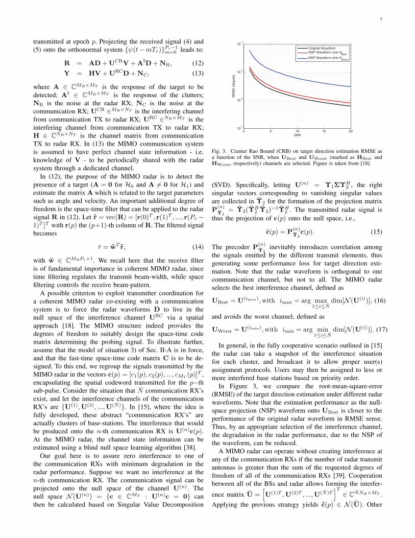
of arrival is given by equation (2) and (6) for the originalradar waveform and the NSP radar waveform, respectively.We are interested in the estimation error of the angle due tothe NSP of radar waveform. In Figure 4, we compare originalangles and estimated angles using ML estimation for differentradar waveforms. Using Algorithms (1) and (2) we can achievealmost similar ML results for original waveform and the NSPwaveform which shows that by choosing HBest to project wecan cause minimum degradation in radar performance. Notethat the ML estimate for the NSP waveform onto HWorstis much degraded from the original waveform and the NSPwaveform onto HBest.In Algorithm (2), we describe an approach to numerically
20 15 10 5 0 5 10 15 2025
20
15
10
5
0
5
10
15
20
25
theta (deg)
thet
a es
timat
e(de
g)
Original WaveformNSP Waveform onto HBest
NSP Waveform onto HWorst
Fig. 4. ML on target direction estimation. HBest and HWorst channels areselected using Algorithms (1) and (2).
40 30 20 10 0 10 20 30 40100
80
60
40
20
0
20
40
θ (deg)
Pow
er (d
B)
Original WaveformNSP Waveform onto small null spaceNSP Waveform onto large null space
Fig. 5. Beampattern of MIMO radar when different values of threshold areused to calculate the null space of interference channels in Algorithm (2).
calculate null space of interference channels. This is animportant approach in the presence of rounding errors andfuzzy data. We select singular values below a certain thresholdand take the corresponding columns of VH
i for our NSPequation. Thus, the value of threshold can be a limitationparameter in the projection algorithm, since, the bigger thevalue of threshold the bigger the null space and the better theperformance of the NSP radar waveform. This can be easilynoticed from Figure 5 where we compare the beampattern oforiginal radar waveform with the NSP waveform when wechoose a larger and a smaller value of threshold. The largervalue of threshold corresponds to the best channel and thesmaller value corresponds to the worst channel, accordingto our definitions in Section III-B. Note that by increasingor decreasing the value of threshold we can manipulate themagnitude of sidelobes. Thus, for the best radar performance,it is desirable to select interference channel with the maximum
2014 IEEE International Symposium on Dynamic Spectrum Access Networks: SSPARC Workshop
12
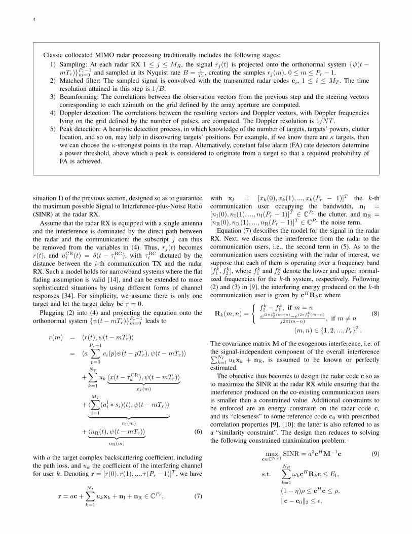
Fig. 3. Cramer Rao Bound (CRB) on target direction estimation RMSE asa function of the SNR, when UBest and UWorst (marked as HBest andHWorst, respectively) channels are selected. Figure is taken from [18].
(SVD). Specifically, letting U(n) = Υ1ΣΥH2 , the right
singular vectors corresponding to vanishing singular valuesare collected in Υ2 for the formation of the projection matrixP
(n)
Υ2= Υ2(ΥH
2 Υ2)−1ΥH2 . The transmitted radar signal is
thus the projection of c(p) onto the null space, i.e.,
c(p) = P(n)
Υ2c(p). (15)
The precoder P(n)
Υ2inevitably introduces correlation among
the signals emitted by the different transmit elements, thusgenerating some performance loss for target direction esti-mation. Note that the radar waveform is orthogonal to onecommunication channel, but not to all. The MIMO radarselects the best interference channel, defined as
UBest = U(imax),with imax = arg max1≤i≤N
dim[N (U(i))], (16)
and avoids the worst channel, defined as
UWorst = U(imin),with imin = arg min1≤i≤N
dim[N (U(i))]. (17)
In general, in the fully cooperative scenario outlined in [15]the radar can take a snapshot of the interference situationfor each cluster, and broadcast it to allow proper user(s)assignment protocols. Users may then be assigned to less ormore interfered base stations based on priority order.
In Figure 3, we compare the root-mean-square-error(RMSE) of the target direction estimation under different radarwaveforms. Note that the estimation performance as the null-space projection (NSP) waveform onto UBest is closer to theperformance of the original radar waveform in RMSE sense.Thus, by an appropriate selection of the interference channel,the degradation in the radar performance, due to the NSP ofthe waveform, can be reduced.
A MIMO radar can operate without creating interference atany of the communication RXs if the number of radar transmitantennas is greater than the sum of the requested degrees offreedom of all of the communication RXs [39]. Cooperationbetween all of the BSs and radar allows forming the interfer-
ence matrix U =[U(1)T ,U(2)T , ...,U(N)T
]T∈ CNNR×MT .
Applying the previous strategy yields c(p) ∈ N (U). Other
8
Radar TXRadar RX Comm TX Comm RXRadar TXRadar RX Comm TX Comm RX
W f
CR I, ,U A AD
vRCodebook Design Channel Info.
WaveformDesign
Received RCU HChannel Info.
Waveform Optimization
Radar Signal Processing
R
D
Received Signal
,U H
Fusion Center
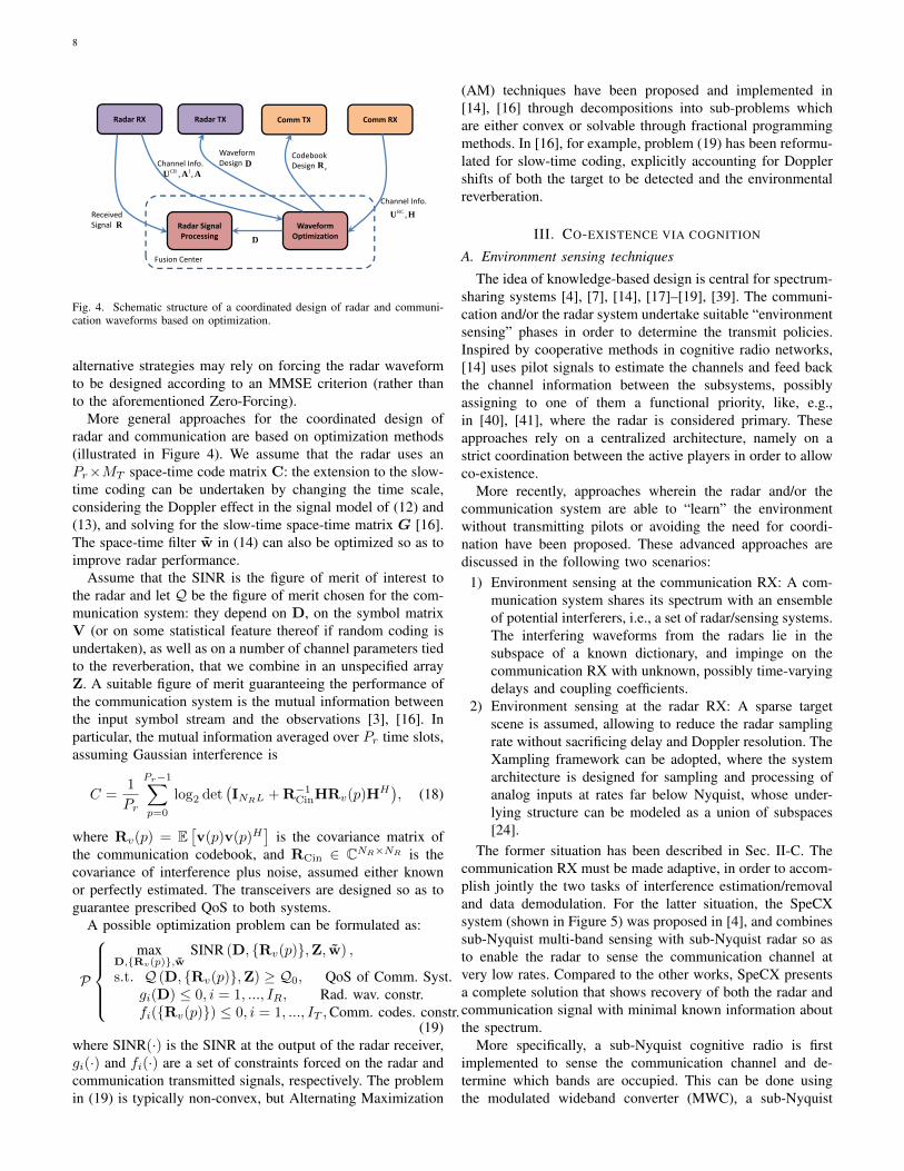
Fig. 4. Schematic structure of a coordinated design of radar and communi-cation waveforms based on optimization.
alternative strategies may rely on forcing the radar waveformto be designed according to an MMSE criterion (rather thanto the aforementioned Zero-Forcing).
More general approaches for the coordinated design ofradar and communication are based on optimization methods(illustrated in Figure 4). We assume that the radar uses anPr×MT space-time code matrix C: the extension to the slow-time coding can be undertaken by changing the time scale,considering the Doppler effect in the signal model of (12) and(13), and solving for the slow-time space-time matrix G [16].The space-time filter w in (14) can also be optimized so as toimprove radar performance.
Assume that the SINR is the figure of merit of interest tothe radar and let Q be the figure of merit chosen for the com-munication system: they depend on D, on the symbol matrixV (or on some statistical feature thereof if random coding isundertaken), as well as on a number of channel parameters tiedto the reverberation, that we combine in an unspecified arrayZ. A suitable figure of merit guaranteeing the performance ofthe communication system is the mutual information betweenthe input symbol stream and the observations [3], [16]. Inparticular, the mutual information averaged over Pr time slots,assuming Gaussian interference is
C =1
Pr
Pr−1∑p=0
log2 det(INRL + R−1
CinHRv(p)HH), (18)
where Rv(p) = E[v(p)v(p)H
]is the covariance matrix of
the communication codebook, and RCin ∈ CNR×NR is thecovariance of interference plus noise, assumed either knownor perfectly estimated. The transceivers are designed so as toguarantee prescribed QoS to both systems.
A possible optimization problem can be formulated as:
P
max
D,{Rv(p)},wSINR (D, {Rv(p)},Z, w) ,
s.t. Q (D, {Rv(p)},Z) ≥ Q0, QoS of Comm. Syst.gi(D) ≤ 0, i = 1, ..., IR, Rad. wav. constr.fi({Rv(p)}) ≤ 0, i = 1, ..., IT ,Comm. codes. constr.
(19)where SINR(·) is the SINR at the output of the radar receiver,gi(·) and fi(·) are a set of constraints forced on the radar andcommunication transmitted signals, respectively. The problemin (19) is typically non-convex, but Alternating Maximization
(AM) techniques have been proposed and implemented in[14], [16] through decompositions into sub-problems whichare either convex or solvable through fractional programmingmethods. In [16], for example, problem (19) has been reformu-lated for slow-time coding, explicitly accounting for Dopplershifts of both the target to be detected and the environmentalreverberation.
III. CO-EXISTENCE VIA COGNITION
A. Environment sensing techniques
The idea of knowledge-based design is central for spectrum-sharing systems [4], [7], [14], [17]–[19], [39]. The communi-cation and/or the radar system undertake suitable “environmentsensing” phases in order to determine the transmit policies.Inspired by cooperative methods in cognitive radio networks,[14] uses pilot signals to estimate the channels and feed backthe channel information between the subsystems, possiblyassigning to one of them a functional priority, like, e.g.,in [40], [41], where the radar is considered primary. Theseapproaches rely on a centralized architecture, namely on astrict coordination between the active players in order to allowco-existence.
More recently, approaches wherein the radar and/or thecommunication system are able to “learn” the environmentwithout transmitting pilots or avoiding the need for coordi-nation have been proposed. These advanced approaches arediscussed in the following two scenarios:
1) Environment sensing at the communication RX: A com-munication system shares its spectrum with an ensembleof potential interferers, i.e., a set of radar/sensing systems.The interfering waveforms from the radars lie in thesubspace of a known dictionary, and impinge on thecommunication RX with unknown, possibly time-varyingdelays and coupling coefficients.
2) Environment sensing at the radar RX: A sparse targetscene is assumed, allowing to reduce the radar samplingrate without sacrificing delay and Doppler resolution. TheXampling framework can be adopted, where the systemarchitecture is designed for sampling and processing ofanalog inputs at rates far below Nyquist, whose under-lying structure can be modeled as a union of subspaces[24].
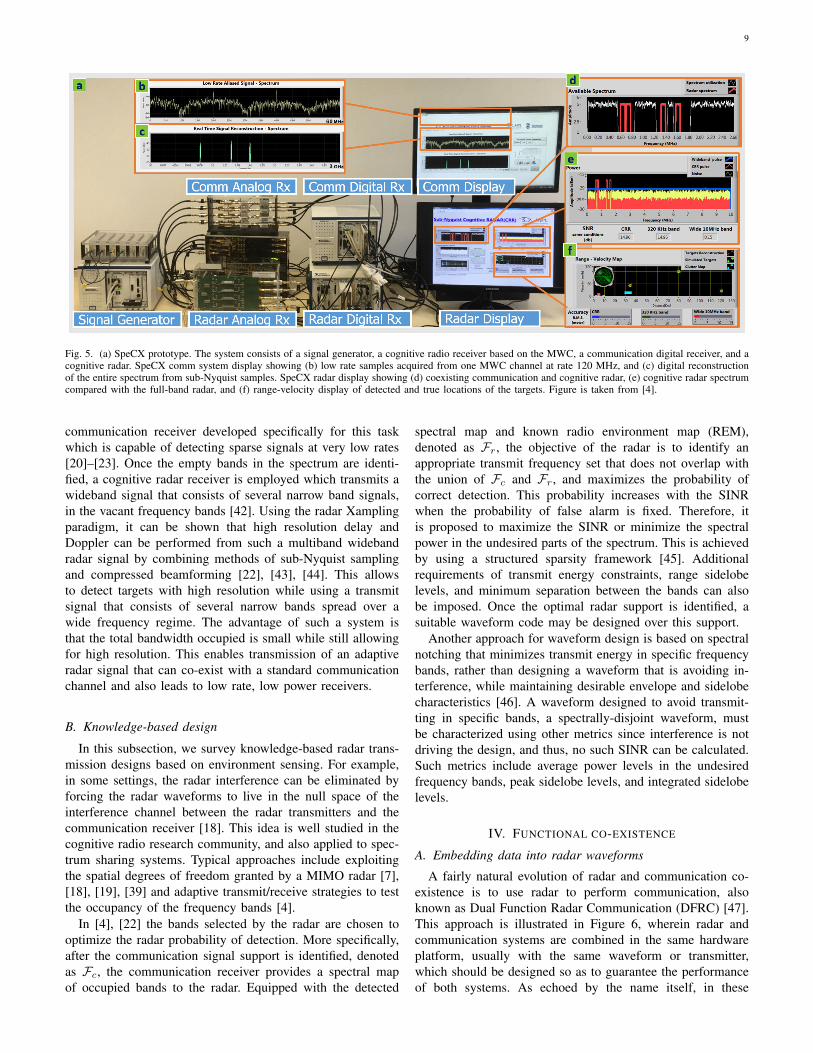
The former situation has been described in Sec. II-C. Thecommunication RX must be made adaptive, in order to accom-plish jointly the two tasks of interference estimation/removaland data demodulation. For the latter situation, the SpeCXsystem (shown in Figure 5) was proposed in [4], and combinessub-Nyquist multi-band sensing with sub-Nyquist radar so asto enable the radar to sense the communication channel atvery low rates. Compared to the other works, SpeCX presentsa complete solution that shows recovery of both the radar andcommunication signal with minimal known information aboutthe spectrum.
More specifically, a sub-Nyquist cognitive radio is firstimplemented to sense the communication channel and de-termine which bands are occupied. This can be done usingthe modulated wideband converter (MWC), a sub-Nyquist
915
Fig. 11. (a) SpeCX prototype. The system consists of a signal generator, a CRo communication analog receiver including the MWC analog front-end board,a communication digital receiver, a CR analog and receiver. SpeCX comm system display showing (b) low rate samples acquired from one MWC channel atrate 120 MHz, and (c) digital reconstruction of the entire spectrum from sub-Nyquist samples. SpeCX radar display showing (d) coexisting communicationand CR, (e) CR spectrum compared with the full-band radar, and (f) range-velocity display of detected and true locations of the targets [40].
Once FC is identified, the communication receiver providesa spectral map of occupied bands to the radar. Equipped withthe detected spectral map and known radio environment map(REM), the objective of the radar is to identify an appropriatetransmit frequency set FR ⊂ F ∖ FC such that the radar’sprobability of detection Pd is maximized. For a fixed proba-bility of false alarm Pfa, the Pd increases with higher signal tointerference and noise ratio (SINR) [91]. Hence, the frequencyselection process can, alternatively, choose to maximize theSINR or minimize the spectral power in the undesired partsof the spectrum. In order to find available bands with leastinterference, a structured sparsity framework [92] is adoptedin [40]. Additional requirements of transmit power constraints,range sidelobe levels, and minimum separation between thebands can also be imposed. At the receiver of this spectrumsharing radar, the sub-Nyquist processing method of [31]recovers the delay-Doppler map from the subset of Fouriercoefficients defined by FR.
This CR system leads to three main advantages. First, theCS reconstruction, performed as presented in [31] on thetransmitted fragmented bands, achieves the same resolutionas traditional Nyquist processing over a significantly smallerbandwidth. Second, by concentrating all the available powerin the transmitted narrow bands rather than over a wide band-width, the CR increases SNR. Finally, this technique allowsfor a dynamic form of the transmitted signal spectrum, whereonly a small portion of the whole bandwidth is used at eachtransmission, enabling spectrum sharing with communicationsignals, as illustrated in Fig. 11(d). There, coexistence betweenradar transmitted bands in red and existing communicationbands in white is shown.
C. SpeCX Prototype
The SpeCX prototype, presented in Fig. 11, demonstratesradar and communication spectrum sharing. It is composedof a CRo receiver and a CR transceiver. At the heart of the
CRo system lies the proprietary modulated wideband converter(MWC) board [30] that implements a sub-Nyquist analogfront-end receiver, which processes signals with Nyquist ratesup to 6 GHz. The card first splits the wideband signal intoM = 4 hardware channels, with an expansion factor of q = 5,yielding Mq = 20 virtual channels after digital expansion (see[93] for more details on the expansion). In each channel,the signal is mixed with a periodic sequence pi(t), whichare truncated versions of Gold Codes [94], generated on adedicated FPGA, with periodic frequency fp = 20 MHz.
Next, the modulated signal passes through an analog anti-aliasing LPF. Finally, the low rate analog signal is sampledby a NI© ADC operating at fs = (q + 1)fp = 120 MHz(with intended oversampling), leading to a total sampling rateof 480 MHz. The digital receiver is implemented on a NI©
PXIe-1065 computer with DC coupled ADC. Since the digitalprocessing is performed at the low rate of 120 MHz, verylow computational load is required in order to achieve realtime recovery. The prototype is fed with RF signals composedof up to Nsig = 5 real communication transmissions, namely10 spectral bands with total bandwidth occupancy of up to200 MHz and varying support, with Nyquist rate of 6 GHz.
The input transmissions then go through an RF combiner,resulting in a dynamic multiband input signal, that enablesfast carrier switching for each of the bands. This input isspecially designed to allow testing the system’s ability torapidly sense the input spectrum and adapt to changes, asrequired by modern CRo and shared spectrum standards, e.g.in the SSPARC program. The system’s effective sampling rate,equal to 480 MHz, is only 8% of the Nyquist rate. Supportrecovery is digitally performed on the low rate samples. Theprototype successfully recovers the support of the communica-tion transmitted bands, as demonstrated in Fig. 11(b)-(c). Oncethe support is recovered, the signal itself can be reconstructedfrom the sub-Nyquist samples. This step is performed in real-time, reconstructing the signal bands one sample at a time.
Fig. 5. (a) SpeCX prototype. The system consists of a signal generator, a cognitive radio receiver based on the MWC, a communication digital receiver, and acognitive radar. SpeCX comm system display showing (b) low rate samples acquired from one MWC channel at rate 120 MHz, and (c) digital reconstructionof the entire spectrum from sub-Nyquist samples. SpeCX radar display showing (d) coexisting communication and cognitive radar, (e) cognitive radar spectrumcompared with the full-band radar, and (f) range-velocity display of detected and true locations of the targets. Figure is taken from [4].
communication receiver developed specifically for this taskwhich is capable of detecting sparse signals at very low rates[20]–[23]. Once the empty bands in the spectrum are identi-fied, a cognitive radar receiver is employed which transmits awideband signal that consists of several narrow band signals,in the vacant frequency bands [42]. Using the radar Xamplingparadigm, it can be shown that high resolution delay andDoppler can be performed from such a multiband widebandradar signal by combining methods of sub-Nyquist samplingand compressed beamforming [22], [43], [44]. This allowsto detect targets with high resolution while using a transmitsignal that consists of several narrow bands spread over awide frequency regime. The advantage of such a system isthat the total bandwidth occupied is small while still allowingfor high resolution. This enables transmission of an adaptiveradar signal that can co-exist with a standard communicationchannel and also leads to low rate, low power receivers.
B. Knowledge-based design
In this subsection, we survey knowledge-based radar trans-mission designs based on environment sensing. For example,in some settings, the radar interference can be eliminated byforcing the radar waveforms to live in the null space of theinterference channel between the radar transmitters and thecommunication receiver [18]. This idea is well studied in thecognitive radio research community, and also applied to spec-trum sharing systems. Typical approaches include exploitingthe spatial degrees of freedom granted by a MIMO radar [7],[18], [19], [39] and adaptive transmit/receive strategies to testthe occupancy of the frequency bands [4].
In [4], [22] the bands selected by the radar are chosen tooptimize the radar probability of detection. More specifically,after the communication signal support is identified, denotedas Fc, the communication receiver provides a spectral mapof occupied bands to the radar. Equipped with the detected
spectral map and known radio environment map (REM),denoted as Fr, the objective of the radar is to identify anappropriate transmit frequency set that does not overlap withthe union of Fc and Fr, and maximizes the probability ofcorrect detection. This probability increases with the SINRwhen the probability of false alarm is fixed. Therefore, itis proposed to maximize the SINR or minimize the spectralpower in the undesired parts of the spectrum. This is achievedby using a structured sparsity framework [45]. Additionalrequirements of transmit energy constraints, range sidelobelevels, and minimum separation between the bands can alsobe imposed. Once the optimal radar support is identified, asuitable waveform code may be designed over this support.
Another approach for waveform design is based on spectralnotching that minimizes transmit energy in specific frequencybands, rather than designing a waveform that is avoiding in-terference, while maintaining desirable envelope and sidelobecharacteristics [46]. A waveform designed to avoid transmit-ting in specific bands, a spectrally-disjoint waveform, mustbe characterized using other metrics since interference is notdriving the design, and thus, no such SINR can be calculated.Such metrics include average power levels in the undesiredfrequency bands, peak sidelobe levels, and integrated sidelobelevels.
IV. FUNCTIONAL CO-EXISTENCE
A. Embedding data into radar waveforms
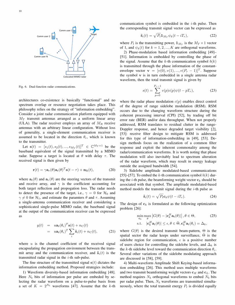
A fairly natural evolution of radar and communication co-existence is to use radar to perform communication, alsoknown as Dual Function Radar Communication (DFRC) [47].This approach is illustrated in Figure 6, wherein radar andcommunication systems are combined in the same hardwareplatform, usually with the same waveform or transmitter,which should be designed so as to guarantee the performanceof both systems. As echoed by the name itself, in these
10
TargetComm user 1
TargetComm user 2
Comm user N
C l d MIMO dColocated MIMO radar
Fig. 6. Dual-function radar communications.
architectures co-existence is basically “functional” and nospectrum overlap or resource negotiation takes place. Thisphilosophy relies on the strategy of “information embedding”.Consider a joint radar communication platform equipped withMT transmit antennas arranged as a uniform linear array(ULA). The radar receiver employs an array of MR receiveantennas with an arbitrary linear configuration. Without lossof generality, a single-element communication receiver isassumed to be located in the direction θc, which is knownto the transmitter.
Let s(t) = [s1(t), s2(t), ..., sMT(t)]T ∈ CMT×1 be the
baseband equivalent of the signal transmitted by a MIMOradar. Suppose a target is located at θ with delay τ . Thereceived signal is then given by
r(t) = γar(θ)at(θ)T s(t− τ) + nR(t), (20)
where at(θ) and ar(θ) are the steering vectors of the transmitand receive array, and γ is the coefficient accounting forboth target reflection and propogation loss. The radar needsto detect the presence of the target, i.e., γ = 0 for H0 andγ 6= 0 for H1, and estimate the paramters θ and τ . Assuminga single-antenna communication receiver and considering asophisticated single-pulse MIMO radar, the baseband signalat the output of the communication receiver can be expressedas
y(t) = uat(θc)T s(t) + nC(t)
= uat(θc)T∑i
si(t) + nC(t), (21)
where u is the channel coefficient of the received signalencapsulating the propagation environment between the trans-mit array and the communication receiver, and si(t) is thetransmitted radar signal in the i-th sub-pulse.
The fine structure of the transmitted signal s(t) dictates theinformation embedding method. Proposed strategies include:
1) Waveform diversity-based information embedding [48].Here Nb bits of information per pulse are embeded by se-lecting the radar waveform on a pulse-to-pulse basis froma set of K = 2Nb waveforms [47]. Assume that the k-th
communication symbol is embedded in the i-th pulse. Thenthe corresponding transmit signal vector can be expressed as
si(t) =√Pt1MT
ψk(t− iTr), (22)
where Pt is the transmitting power, 1MTis the MT ×1 vector
of 1, and ψk(t) for k = 1, 2, ...,K are orthogonal waveforms.2) Phase-modulation based information embedding [49]–
[51]. Information is embedded by controlling the phase ofthe signal. Assume that the k-th communication symbol b(k)is transmitted through the phase information of the constant-envelope vector v = [v(0), v(1), ..., v(Pr − 1)]T . Supposethe symbol v is in turn embedded in a single antenna radarwaveform, then the total transmit signal is given by
s(t) =
Pr−1∑p=0
v(p)c(p)ψ(t− pTr), (23)
where the radar phase modulation c(p) enables direct controlof the degree of range sidelobe modulation (RSM). RSMoccurs due to the changing waveform structure during thecoherent processing interval (CPI) [52], by trading off biterror rate (BER) and/or data throughput. When not properlyaddressed, RSM translates to residual clutter in the range-Doppler response, and hence degraded target visibility [2],[53]: receive filter design to mitigate RSM is addressedfor this type of information-embedding in [49], [53]. De-sign methods focus on the realization of a common filterresponse and exploit the inherent commonality among theradar/communication waveforms. It is worth noting that phasemodulation will also inevitably lead to spectrum alterationof the radar waveform, which may result in energy leakageoutside the assigned bandwidth [54].
3) Sidelobe amplitude modulated-based communications[55]–[57]. To embed the k-th communication symbol b(k) dur-ing the i-th pulse, the beamforming weight vector ck should beassociated with that symbol. The amplitude modulated-basedmethod models the transmit signal during the i-th pulse as
si(t) =√Ptckψ(t− iTr). (24)
The design of ck is formulated as the following optimizationproblem [26]:
minck
maxθ
∣∣G(θ)− |cHk at(θ)|∣∣ , θ ∈ Θ, (25)
s.t. |cHk at(θ)| ≤ ε, θ ∈ Θ, cHk at(θc) = ∆k,
where G(θ) is the desired transmit beam-pattern, Θ is thespatial sector the radar keeps under surveillance, Θ is thesidelobe region for communication, ε is a positive numberof users choice for controlling the sidelobe levels, and ∆k isthe k-th sidelobe level toward the communication direction θc.Several other variations of the sidelobe modulating approachare discussed in [58], [59].
4) Multi-waveform Amplitude Shift Keying-based informa-tion embedding [26]. This method uses multiple waveformsand two transmit beamforming weight vectors cH and cL. Themethod requires Nb orthogonal waveforms to embed Nb bitsper radar pulse. Then, Nb waveforms are transmitted simulta-neously, where the total transmit energy Pt is divided equally
11
among the Nb waveforms. Every transmitted waveform isused to deliver one information bit and the waveform ψk(t),k = 1, 2, ..., Nb, is radiated either via cH for bi(k) = 0 or cLfor bi(k) = 1 [47]. The transmit signal is then
si(t) =√PtNb
Nb∑k=1
((1− bi(k))cH + bi(k)cL)ψk(t− iTr).(26)
B. Radar employing communication waveforms
Another evolution of functional co-existence is to exploit thewaveforms transmitted by a communication network in orderto perform sensing (radar) functions. Without loss of general-ity, we assume a single-element communication transmitter (ora phased-array with an extremely directional beam-pattern).The baseband signal at the communication TX is given by (3)with xi(t) and vi(p) replaced by x(t) and v(p), respectively.
Suppose the radar is equipped with MR antennas and thecommunication TX is located at angle θc. There are a numberof scattering centers (targets), the i-th of which is with pathdelay τi, Doppler shift νi and angle θi. Let γi be the coefficientaccounting for both target reflection and propagation loss ofthe i-th target. The response from the communication TX tothe radar RX in (4) can be re-written as
uCRj (t) = uar,j(θc)δ(t− τc) +
∑i
γiar,j(θi)ej2πνitδ(t− τi),
where ar,j(θ) is the angle response of the j-th radar RX, u isthe coefficient of the direct path between the communicationTX and radar RX, and τc is the delay of the direct path. As noradar TX is used, the baseband equivalent signal at the radarRX can be obtained from (4) with
∑MT
i=1 ai,jsi(t − τi,j) and∑MT
i=1(aIi,j ∗ si)(t) removed:
r(t) = uar(θc)x(t− τc)
+∑i
γiej2πνitar(θi)x(t− τi) + nR(t), (27)
where ar(θ) = [ar,1(θ), ar,2(θ), ..., ar,MR(θ)]T ∈ CMR is the
receive steering vector.One option to use a communication waveform x(t) for
sensing is the opportunistic radar based on the 802.11adstandard proposed in [29], [30]. The adoption of the 802.11adstandard for 5-th Generation (5G) wireless systems and theexploitation of millimeter Waves (mmWaves) in the 28 and60 GHz bandwidths [60] immediately raised interest towardsthe exploitation for sensing applications of some key charac-teristics of the proposed standard. Indeed, mmWaves sufferfrom heavy atmospheric attenuation, resonance in the O2
molecule, absorption by rain, and almost complete shadow-ing by obstacles, thus requiring Line-of-Sight (LOS) pathsbetween transmitter and receiver. This is in turn achievablethanks to extremely directional beam-patterns and frequentscanning procedures during which the surrounding space isswept in search of nodes willing to establish directional links.As a consequence, the so-called Sector Level Sweep (SLS)phase of the beamforming training protocol provides signals
of opportunity which can be exploited for short-range obstacledetection, typically in automotive applications [29]. In such aphase, the transmitted signal consists of a preamble, containingconcatenated complementary Golay codes, and a payload, con-taining data. The proposed architectures rely on the presenceof a receiver, co-located with the wireless transmitter andaccessing some key information such as the timing, as well aspart if not all of the transmitted signal. With reference to (27),τc = 0, u = 0 because there is no direct path, and x(t) is eitherpartially known, since the preamble has a fixed structure, orcompletely known, if the transmitted data are communicatedto the radar receiver.
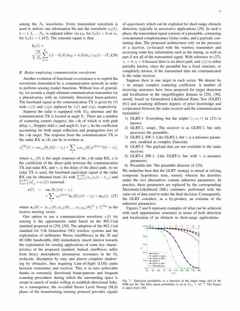
Suppose there is one target in each sector. We denote byγ its unique complex scattering coefficient. A number ofreceiving structures have been proposed for target detectionand localization in the range/Doppler domain in [29], [30],mostly based on Generalized Likelihood Ratio Test (GLRT)[61] and assuming different degrees of prior knowledge andcooperation between the radar receiver and the communicationtransmitter:
1) GLRT-1: Everything but the triplet (γ, ν, τ) in (27) isknown;
2) GLRT-1, simpl.: The receiver is as GLRT-1, but onlyprocesses the preamble;
3) GLRT-2, SW-1: Like GLRT-1, but γ is a nuisance param-eter, modeled as complex Gaussian;
4) GLRT-3: The payload data are not available to the radarreceiver;
5) GLRT-4 SW-1: Like GLRT-3, but with γ a nuisanceparameter;
6) Preamble-det: The preamble detector of [29].We underline here that the GLRT strategy is aimed at solvingcomposite hypotheses tests, namely wherein the densitiesunder the two alternatives contain unknown parameters. Inpractice, these parameters are replaced by the correspondingMaximum-Likelihood (ML) estimates, performed with thesame set of data used to make the final decision. Consequently,the GLRT considers, as a by-product, an estimate of theunknown parameters.
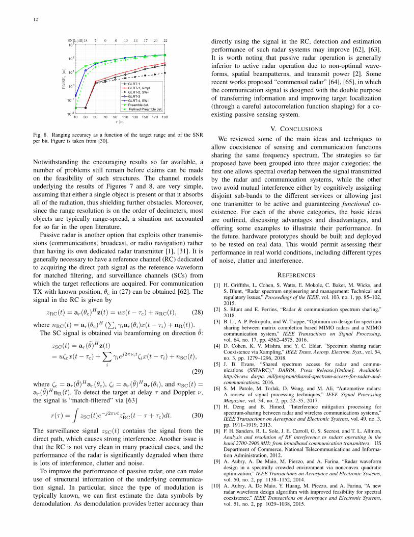
Figures 7 and 8 represent examples of what can be achievedwith such opportunistic structures in terms of both detectionand localization of an obstacle in short-range applications.
10 30 50 70 90 110 130 150 170 190r [m]
0
0.2
0.4
0.6
0.8
1
Pd
GLRT-1GLRT-1, simpl.GLRT-2, SW-IGLRT-3GLRT-4, SW-IPreamble det.
SNRb[dB]18 7 0 -6 -10 -14 -17 -20 -22
Fig. 7. Detection probability as a function of the target range and of theSNR per bit. The false alarm probability is set at Pfa = 10−4. The Figureis taken from [30].
12
10 30 50 70 90 110 130 150 170 190r [m]
10-2
10-1
100
101
102
103
RMSEr[m
]
GLRT-1GLRT-1, simpl.GLRT-2, SW-IGLRT-3GLRT-4, SW-IPreamble det. Refined Preamble det.
SNRb[dB]18 7 0 -6 -10 -14 -17 -20 -22
Fig. 8. Ranging accuracy as a function of the target range and of the SNRper bit. Figure is taken from [30].
Notwithstanding the encouraging results so far available, anumber of problems still remain before claims can be madeon the feasibility of such structures. The channel modelsunderlying the results of Figures 7 and 8, are very simple,assuming that either a single object is present or that it absorbsall of the radiation, thus shielding further obstacles. Moreover,since the range resolution is on the order of decimeters, mostobjects are typically range-spread, a situation not accountedfor so far in the open literature.
Passive radar is another option that exploits other transmis-sions (communications, broadcast, or radio navigation) ratherthan having its own dedicated radar transmitter [1], [31]. It isgenerally necessary to have a reference channel (RC) dedicatedto acquiring the direct path signal as the reference waveformfor matched filtering, and surveillance channels (SCs) fromwhich the target reflections are acquired. For communicationTX with known position, θc in (27) can be obtained [62]. Thesignal in the RC is given by
zRC(t) = ar(θc)Hz(t) = ux(t− τc) + nRC(t), (28)
where nRC(t) = ar(θc)H (∑i γiar(θi)x(t− τi) + nR(t)).
The SC signal is obtained via beamforming on direction θ:
zSC(t) = ar(θ)Hz(t)
= uζcx(t− τc) +∑i
γiej2πνitζix(t− τi) + nSC(t),
(29)
where ζc = ar(θ)Har(θc), ζi = ar(θ)
Har(θi), and nSC(t) =ar(θ)
HnR(t). To detect the target at delay τ and Doppler ν,the signal is “match-filtered” via [63]
r(τ) =
∫zSC(t)e−j2πνtz∗RC(t− τ + τc)dt. (30)
The surveillance signal zSC(t) contains the signal from thedirect path, which causes strong interference. Another issue isthat the RC is not very clean in many practical cases, and theperformance of the radar is significantly degraded when thereis lots of interference, clutter and noise.
To improve the performance of passive radar, one can makeuse of structural information of the underlying communica-tion signal. In particular, since the type of modulation istypically known, we can first estimate the data symbols bydemodulation. As demodulation provides better accuracy than
directly using the signal in the RC, detection and estimationperformance of such radar systems may improve [62], [63].It is worth noting that passive radar operation is generallyinferior to active radar operation due to non-optimal wave-forms, spatial beampatterns, and transmit power [2]. Somerecent works proposed “commensal radar” [64], [65], in whichthe communication signal is designed with the double purposeof transferring information and improving target localization(through a careful autocorrelation function shaping) for a co-existing passive sensing system.
V. CONCLUSIONS
We reviewed some of the main ideas and techniques toallow coexistence of sensing and communication functionssharing the same frequency spectrum. The strategies so farproposed have been grouped into three major categories: thefirst one allows spectral overlap between the signal transmittedby the radar and communication systems, while the othertwo avoid mutual interference either by cognitively assigningdisjoint sub-bands to the different services or allowing justone transmitter to be active and guaranteeing functional co-existence. For each of the above categories, the basic ideasare outlined, discussing advantages and disadvantages, andoffering some examples to illustrate their performance. Inthe future, hardware prototypes should be built and deployedto be tested on real data. This would permit assessing theirperformance in real world conditions, including different typesof noise, clutter and interference.
REFERENCES
[1] H. Griffiths, L. Cohen, S. Watts, E. Mokole, C. Baker, M. Wicks, andS. Blunt, “Radar spectrum engineering and management: Technical andregulatory issues,” Proceedings of the IEEE, vol. 103, no. 1, pp. 85–102,2015.
[2] S. Blunt and E. Perrins, “Radar & communication spectrum sharing,”2018.
[3] B. Li, A. P. Petropulu, and W. Trappe, “Optimum co-design for spectrumsharing between matrix completion based MIMO radars and a MIMOcommunication system,” IEEE Transactions on Signal Processing,vol. 64, no. 17, pp. 4562–4575, 2016.
[4] D. Cohen, K. V. Mishra, and Y. C. Eldar, “Spectrum sharing radar:Coexistence via Xampling,” IEEE Trans. Aerosp. Electron. Syst., vol. 54,no. 3, pp. 1279–1296, 2018.
[5] J. B. Evans, “Shared spectrum access for radar and commu-nications (SSPARC),” DARPA, Press Release.[Online]. Available:http://www. darpa. mil/program/shared-spectrum-access-for-radar-and-communications, 2016.
[6] S. M. Patole, M. Torlak, D. Wang, and M. Ali, “Automotive radars:A review of signal processing techniques,” IEEE Signal ProcessingMagazine, vol. 34, no. 2, pp. 22–35, 2017.
[7] H. Deng and B. Himed, “Interference mitigation processing forspectrum-sharing between radar and wireless communications systems,”IEEE Transactions on Aerospace and Electronic Systems, vol. 49, no. 3,pp. 1911–1919, 2013.
[8] F. H. Sanders, R. L. Sole, J. E. Carroll, G. S. Secrest, and T. L. Allmon,Analysis and resolution of RF interference to radars operating in theband 2700-2900 MHz from broadband communication transmitters. USDepartment of Commerce, National Telecommunications and Informa-tion Administration, 2012.
[9] A. Aubry, A. De Maio, M. Piezzo, and A. Farina, “Radar waveformdesign in a spectrally crowded environment via nonconvex quadraticoptimization,” IEEE Transactions on Aerospace and Electronic Systems,vol. 50, no. 2, pp. 1138–1152, 2014.
[10] A. Aubry, A. De Maio, Y. Huang, M. Piezzo, and A. Farina, “A newradar waveform design algorithm with improved feasibility for spectralcoexistence,” IEEE Transactions on Aerospace and Electronic Systems,vol. 51, no. 2, pp. 1029–1038, 2015.
13
[11] L. Zheng, M. Lops, and X. Wang, “Adaptive interference removalfor uncoordinated radar/communication coexistence,” IEEE Journal ofSelected Topics in Signal Processing, vol. 12, no. 1, pp. 45–60, 2018.
[12] F. Liu, C. Masouros, A. Li, T. Ratnarajah, and J. Zhou, “MIMO radar andcellular coexistence: A power-efficient approach enabled by interferenceexploitation,” IEEE Transactions on Signal Processing, 2018.
[13] N. Nartasilpa, A. Salim, D. Tuninetti, and N. Devroye, “Communicationssystem performance and design in the presence of radar interference,”IEEE Transactions on Communications, vol. XX, no. X, p. XXX, 2018.
[14] B. Li and A. P. Petropulu, “Joint transmit designs for coexistence ofMIMO wireless communications and sparse sensing radars in clutter,”IEEE Transactions on Aerospace and Electronic Systems, vol. 53, no. 6,pp. 2846–2864, 2017.
[15] J. Mahal, A. Khawar, A. Abdelhadi, and C. Clancy, “Spectral coexistenceof MIMO radar and MIMO cellular systems,” IEEE Trans. Aerospaceand Electronic Systems, vol. 53, no. 2, pp. 655–668, 2017.
[16] J. Qian, M. Lops, L. Zheng, X. Wang, and Z. He, “Joint system designfor co-existence of MIMO radar and MIMO communication,” IEEETransactions on Signal Processing, 2018.
[17] L. Zheng, M. Lops, X. Wang, and E. Grossi, “Joint design of overlaidcommunication systems and pulsed radars,” IEEE Transactions onSignal Processing, vol. 66, no. 1, pp. 139–154, 2018.
[18] A. Khawar, A. Abdel-Hadi, and T. C. Clancy, “Spectrum sharingbetween S-band radar and LTE cellular system: A spatial approach,”in Dynamic Spectrum Access Networks (DYSPAN), 2014 IEEE Interna-tional Symposium on. IEEE, 2014, pp. 7–14.
[19] A. Puglielli, A. Townley, G. LaCaille, V. Milovanovic, P. Lu, K. Trot-skovsky, A. Whitcombe, N. Narevsky, G. Wright, T. Courtade et al.,“Design of energy-and cost-efficient massive MIMO arrays,” Proceed-ings of the IEEE, vol. 104, no. 3, pp. 586–606, 2016.
[20] M. Mishali, Y. C. Eldar, O. Dounaevsky, and E. Shoshan, “Xampling:Analog to digital at sub-Nyquist rates,” IET circuits, devices & systems,vol. 5, no. 1, pp. 8–20, 2011.
[21] M. Mishali and Y. C. Eldar, “From theory to practice: Sub-Nyquistsampling of sparse wideband analog signals,” IEEE Journal of SelectedTopics in Signal Processing, vol. 4, no. 2, pp. 375–391, 2010.
[22] Y. C. Eldar, Sampling theory: Beyond bandlimited systems. CambridgeUniversity Press, 2015.
[23] D. Cohen, S. Tsiper, and Y. C. Eldar, “Analog-to-Digital cognitive radio:Sampling, detection, and hardware,” IEEE Signal Processing Magazine,vol. 35, no. 1, pp. 137–166, 2018.
[24] D. Cohen and Y. C. Eldar, “Sub-nyquist radar systems: Temporal,spectral, and spatial compression,” IEEE Signal Processing Magazine,vol. 35, no. 6, pp. 35–58, 2018.
[25] S. D. Blunt, P. Yathan, and J. Stiles, “Intrapulse radar-embedded com-munications,” IEEE Transactions on Aerospace and Electronic Systems,vol. 46, no. 3, pp. 1185–1200, 2010.
[26] A. Hassanien, M. G. Amin, Y. D. Zhang, and F. Ahmad, “Dual-FunctionRadar-Communications: Information Embedding Using Sidelobe Con-trol and Waveform Diversity.” IEEE Trans. Sig. Proc, vol. 64, no. 8, pp.2168–2181, 2016.
[27] Z. Geng, R. Xu, H. Deng, and B. Himed, “Fusion of radar sensing andwireless communications by embedding communication signals into theradar transmit waveform,” IET Radar, Sonar, Navigation, vol. 12, no. 6,pp. 632–630, 2018.
[28] F. Liu, L. Zhou, C. Masouros, A. Li, W. Luo, and A. Petropulu, “To-ward dual-functional radar-communication systems: Optimal waveformdesign,” IEEE Transactions on Signal Processing, vol. 66, no. 16, pp.4264–4279, Aug 2018.
[29] P. Kumari, N. Gonzalez-Prelcic, and R. W. Heath, “Investigating theIEEE 802.11ad standard for millimeter wave automotive radar,” inVehicular Technology Conference (VTC Fall), 2015 IEEE 82nd. IEEE,2015, pp. 1–5.
[30] E. Grossi, M. Lops, L. Venturino, and A. Zappone, “Opportunistic radarin 802.11ad networks,” IEEE Transactions on Signal Processing, vol. 66,no. 9, pp. 2441–2454, 2018.
[31] H. Griffiths, “Passive bistatic radar and waveform diversity,” DefenceAcademy of the United Kingdom Shrivenham (United Kingdom), Tech.Rep., 2009.
[32] S. D. Blunt and E. L. Mokole, “Overview of radar waveform diversity,”IEEE Aerospace and Electronic Systems Magazine, vol. 31, no. 11, pp.2–42, 2016.
[33] A. De Maio and M. Lops, “Design principles of MIMO radar detectors,”IEEE Transactions on Aerospace and Electronic Systems, vol. 43, no. 3,pp. 886–898, 2007.
[34] A. Aubry, A. DeMaio, A. Farina, and M. Wicks, “Knowledge-aided(potentially cognitive) transmit signal and receive filter design in signal-dependent clutter,” IEEE Transactions on Aerospace and ElectronicSystems, vol. 49, no. 1, pp. 93–117, 2013.
[35] L. Zheng, M. Lops, and X. Wang, “Adaptive Interference Removal forUn-coordinated Radar/Communication Co-existence,” IEEE Journal ofSelected Topics in Signal Processing, vol. 12, no. 1, pp. 1–16, 2018.
[36] M. Piezzo, A. De Maio, A. Aubry, and A. Farina, “Cognitive radar wave-form design for spectral coexistence,” in 2013 IEEE Radar Conference.IEEE, 2013.
[37] A. Aubry, A. De Maio, M. Piezzo, M. Naghsh, M. Soltananian, andS. Petre, “Cognitive radar waveform design for spectral coexistence insignal-dependent interference,” in 2014 IEEE Radar Conference. IEEE,2014, pp. 474–478.
[38] Y. Noam and A. J. Goldsmith, “Blind null-space learning for MIMOunderlay cognitive radio with primary user interference adaptation,”IEEE Transactions on Wireless Communications, vol. 12, no. 4, pp.1722–1734, 2013.
[39] A. Babaei, W. H. Tranter, and T. Bose, “A practical precoding ap-proach for radar/communications spectrum sharing,” in Cognitive RadioOriented Wireless Networks (CROWNCOM), 2013 8th InternationalConference on. IEEE, 2013, pp. 13–18.
[40] R. Zhang and Y.-C. Liang, “Exploiting multi-antennas for opportunisticspectrum sharing in cognitive radio networks,” IEEE Journal of selectedtopics in signal processing, vol. 2, no. 1, pp. 88–102, 2008.
[41] R. Zhang, Y.-C. Liang, and S. Cui, “Dynamic resource allocation incognitive radio networks,” IEEE Signal Processing Magazine, vol. 27,no. 3, pp. 102–114, 2010.
[42] D. Cohen, A. Dikopoltsev, R. Ifraimov, and Y. C. Eldar, “Towards sub-Nyquist cognitive radar,” in Radar Conference (RadarConf), 2016 IEEE.IEEE, 2016, pp. 1–4.
[43] O. Bar-Ilan and Y. C. Eldar, “Sub-Nyquist radar via Doppler focusing,”IEEE Transactions on Signal Processing, vol. 62, no. 7, pp. 1796–1811,2014.
[44] E. Baransky, G. Itzhak, N. Wagner, I. Shmuel, E. Shoshan, and Y. Eldar,“Sub-Nyquist radar prototype: Hardware and algorithm,” IEEE Transac-tions on Aerospace and Electronic Systems, vol. 50, no. 2, pp. 809–822,2014.
[45] J. Huang, T. Zhang, and D. Metaxas, “Learning with structured sparsity,”Journal of Machine Learning Research, vol. 12, no. Nov, pp. 3371–3412,2011.
[46] S. W. Frost and B. Rigling, “Sidelobe predictions for spectrally-disjointradar waveforms,” in Radar Conference (RADAR), 2012 IEEE. IEEE,2012, pp. 0247–0252.
[47] A. Hassanien, M. G. Amin, Y. D. Zhang, and F. Ahmad, “Signalingstrategies for dual-function radar communications: an overview,” IEEETransactions on Aerospace and Electronic Systems Magazine, vol. 31,no. 10, pp. 36–45, 2016.
[48] S. D. Blunt, M. R. Cook, and J. Stiles, “Embedding information intoradar emissions via waveform implementation,” in Waveform Diversityand Design Conference (WDD), 2010 International. IEEE, 2010, pp.000 195–000 199.
[49] C. Sahin, J. Jakabosky, P. M. McCormick, J. G. Metcalf, and S. D.Blunt, “A novel approach for embedding communication symbols intophysical radar waveforms,” in Radar Conference (RadarConf), 2017IEEE. IEEE, 2017, pp. 1498–1503.
[50] C. Sahin, J. G. Metcalf, A. Kordik, T. Kendo, and T. Corigliano, “Ex-perimental validation of phase-attached radar/communication (PARC)waveforms: Radar performance,” 2018.
[51] M. J. Nowak, Z. Zhang, L. LoMonte, M. Wicks, and Z. Wu, “Mixed-modulated linear frequency modulated radar-communications,” IETRadar, Sonar & Navigation, vol. 11, no. 2, pp. 313–320, 2016.
[52] J. Tian, W. Cui, and S. Wu, “A novel method for parameter estimationof space moving targets,” IEEE Geoscience and Remote Sensing Letters,vol. 11, no. 2, pp. 389–393, 2014.
[53] C. Sahin, J. G. Metcalf, and S. D. Blunt, “Filter design to address rangesidelobe modulation in transmit-encoded radar-embedded communica-tions,” in Radar Conference (RadarConf), 2017 IEEE. IEEE, 2017, pp.1509–1514.
[54] X. Chen, Z. Liu, Y. Liu, and Z. Wang, “Energy leakage analysis of theradar and communication integrated waveform,” IET Signal Processing,vol. 12, no. 3, pp. 375–382, 2018.
[55] J. Euziere, R. Guinvarc’h, M. Lesturgie, B. Uguen, and R. Gillard,“Dual function radar communication time-modulated array,” in RadarConference (Radar), 2014 International. IEEE, 2014, pp. 1–4.
[56] P. M. McCormick, S. D. Blunt, and J. G. Metcalf, “Simultaneous radarand communications emissions from a common aperture, Part I: Theory,”

14
in Radar Conference (RadarConf), 2017 IEEE. IEEE, 2017, pp. 1685–1690.
[57] P. M. McCormick, B. Ravenscroft, S. D. Blunt, A. J. Duly, andJ. G. Metcalf, “Simultaneous radar and communication emissions froma common aperture, Part II: Experimentation,” in Radar Conference(RadarConf), 2017 IEEE. IEEE, 2017, pp. 1697–1702.
[58] A. Hassanien, M. G. Amin, Y. D. Zhang, and F. Ahmad, “Efficientsidelobe ASK based dual-function radar-communications,” in RadarSensor Technology XX, vol. 9829. International Society for Opticsand Photonics, 2016, p. 98290K.
[59] ——, “Phase-modulation based dual-function radar-communications,”IET Radar, Sonar & Navigation, vol. 10, no. 8, pp. 1411–1421, 2016.
[60] T. S. Rappaport, S. Sun, R. Mayzus, H. Zhao, Y. Azar, K. Wang, G. N.Wong, G. N. Schulz, Samimi, and F. Gutierrez, “Millimeter wave mobilecommunications for 5g cellular: It will work!” IEEE Access, vol. 1, pp.335–349, 2013.
[61] S. Kay, “Fundamentals of statistical signal processing, volume II:Detection theory,” 1993.
[62] L. Zheng and X. Wang, “Super-resolution delay-doppler estimation forOFDM passive radar,” IEEE Transactions on Signal Processing, vol. 65,no. 9, pp. 2197–2210, 2017.
[63] C. R. Berger, B. Demissie, J. Heckenbach, P. Willett, and S. Zhou,“Signal processing for passive radar using OFDM waveforms,” IEEEJournal of Selected Topics in Signal Processing, vol. 4, no. 1, pp. 226–238, 2010.
[64] H. Griffiths, I. Darwazeh, and M. Inggs, “Waveform design for com-mensal radar,” in Radar Conference (RadarCon), 2015 IEEE. IEEE,2015, pp. 1456–1460.
[65] B. Ravenscroft, P. M. McCormick, S. D. Blunt, J. Jakabosky, and J. G.Metcalf, “Tandem-hopped OFDM communications in spectral gaps ofFM noise radar,” in Radar Conference (RadarConf), 2017 IEEE. IEEE,2017, pp. 1262–1267.
Le Zheng (M’17) received the B.S. degree in Communication Engineeringfrom Northwestern Polytechnical University (NWPU), Xi’an, China, in 2009and the Ph.D. degree in Target Detection and Recognition from the BeijingInstitute of Technology (BIT), Beijing, China, in 2015. From Feb, 2015 toFeb, 2018, he was a Postdoctoral Researcher in the Electrical EngineeringDepartment of Columbia University, New York, USA. Now he works atAptiv (formerly Delphi), CA, USA as a Principal Radar Systems Engineer.His research interests lie in the areas of radar system, statistical signal pro-cessing, wireless communication and high-performance hardware for signalprocessing.
Marco Lops is a professor with the Department of Electrical Engineeringand Information Technologies at the University ”Federico II” of Naples. Heobtained his “Laurea” and his Ph.D. degrees from “Federico II” University(Naples), where he was assistant (1989-1991) and associate (1991-2000)professor. From March 2000 to November 2018 he was a professor atUniversity of Cassino and Southern Lazio and, in 2009-2011, he was also withENSEEIHT (Toulouse), first as full professor and then as visiting professor. Infall 2008 he was a visiting professor at University of Minnesota and in spring2009 at Columbia University. He was selected to serve as a DistinguishedLecturer for the Signal processing Society during 2018-2020. His researchinterests are in detection and estimation, with emphasis on communicationsand radar signal processing.
Yonina C. Eldar is a Professor in the Department of Electrical Engineeringat the Technion - Israel Institute of Technology, Haifa, Israel, where she holdsthe Edwards Chair in Engineering. She is also an Adjunct Professor at DukeUniversity, a Research Affiliate with the Research Laboratory of Electronics atMIT and was a Visiting Professor at Stanford University, Stanford, CA. She isa member of the Israel Academy of Sciences and Humanities, an IEEE Fellowand a EURASIP Fellow. She has received many awards for excellence inresearch and teaching, including the IEEE Signal Processing Society TechnicalAchievement Award, the IEEE/AESS Fred Nathanson Memorial Radar Award,the IEEE Kiyo Tomiyasu Award, the Michael Bruno Memorial Award fromthe Rothschild Foundation, the Weizmann Prize for Exact Sciences, and theWolf Foundation Krill Prize for Excellence in Scientific Research. She is theEditor in Chief of Foundations and Trends in Signal Processing, and servesthe IEEE on several technical and award committees.
Xiaodong Wang (S’98-M’98-SM’04-F’08) received the Ph.D degree inElectrical Engineering from Princeton University. He is a Professor ofElectrical Engineering at Columbia University in New York. Dr. Wang’sresearch interests fall in the general areas of computing, signal processingand communications,and has published extensively in these areas. Among hispublications is a book entitled “Wireless Communication Systems: AdvancedTechniques for Signal Reception”, published by Prentice Hall in 2003. Hiscurrent research interests include wireless communications, statistical signalprocessing, and genomic signal processing. Dr. Wang received the 1999 NSFCAREER Award, the 2001 IEEE Communications Society and InformationTheory Society Joint Paper Award, and the 2011 IEEE CommunicationSociety Award for Outstanding Paper on New Communication Topics. He hasserved as an Associate Editor for the IEEE Transactions on Communications,the IEEE Transactions on Wireless Communications, the IEEE Transactionson Signal Processing, and the IEEE Transactions on Information Theory. Heis a Fellow of the IEEE and listed as an ISI Highly-cited Author.
Related Documents
![arXiv:0802.4033v3 [math.OA] 28 Jul 2008 · results in classical analysis, such as Wiener’s Theorem on functions with ab-solutely convergent Fourier series, and standard existence](https://static.cupdf.com/doc/110x72/5f1c856fd8175d742d24e2ed/arxiv08024033v3-mathoa-28-jul-2008-results-in-classical-analysis-such-as-wieneras.jpg)


![arXiv:1105.2897v1 [math.NT] 14 May 2011 · 2018-10-16 · arXiv:1105.2897v1 [math.NT] 14 May 2011 ON THE EXISTENCE OF MAXIMAL ORDERS CHIA-FU YU Abstract. We generalize the existence](https://static.cupdf.com/doc/110x72/5e6c3c6630ec3c66364b2db4/arxiv11052897v1-mathnt-14-may-2011-2018-10-16-arxiv11052897v1-mathnt.jpg)

