R RAASE. See Viverrines. RABBIT FEVER. See Tularemia. RABBITFISH (Chimaera monstrosa). One of seventeen species of Chimaeridae, the rabbitfish is a bottom dweller of the northeastern At- lantic, from Iceland and Norway to northern Africa, as well as of the western and central Mediterranean. The habitat chiefly is the continen- tal shelf at depths of about 200 meters (650 feet), although it is occa- sionally found at considerably greater depths. The coloration is silver- gray, with a violet sheen on the upper side and a dark marble pattern underneath. The unpaired fins have black seams. The rabbitfish Ani !' ketch of th e rabbitfi h ( himaera monstrosa). achieves a length of about 1.5 meters (5 feet). The fish is so named because of its slight resemblance to a rabbit in the eye, mouth, and throat area. The fish feeds on various crustaceans, mollusks, echinoderms and small floor-dwelling fishes. Although the fish is not suitable as a source of food for people, the liver, which amounts to about one-third of the total body weight, is a valuable source of oil. Fishermen dealing with rabbitfishes must proceed cautiously because the stinging spine of the dorsal spine is poisonous and lethal injuries have been reported from accidents by contacting them. RABBITS AND HARES. At one time, these leaping animals were classified with other gnawing animals in the order of Rodentia. They are now placed in their own order of mammals, i.e., Lagomorpha (leap- ing mammals). Nevertheless, in a general sense, rabbits are rodents with long ears, large hind legs, and small front legs. Some species bur- row and others occupy similar retreats which they do not make for themselves. Many members of this group are called hares. There is no sharp distinction between the terms except in their established applica- tion to certain species. Differences in the young sometimes are used to distinguish between the rabbits and the hares. Rabbits are born naked, blind, quite helpless and in a fur-lined nest. The young are smaller than the baby hares. The young hares are born in small, open dens on top of the ground, are fully haired and with eyes open. They hop about almost immediately after birth. Rabbits are found on all continents, although they were introduced into the Australian region. In New South Wales the introduced stock threatened to crowd out even the settlers by its destruction of vegeta- tion. Millions of the animals have been killed per year and the exporta- tion of their hides has somewhat offset their destructiveness. Sudden reduction in numbers is caused by epidemics. Myxomatosis, a virus disease, is quickly fatal to rabbits and the artificial creation of this dis- ease in Australia has reduced the enormous numbers of European rab- bits, Oryctolagus (Lepus), which existed in the absence of natural ene- mies. In North America the common or cottontail rabbit, Sylvilagus flori- danus, and a few closely related species are widely distributed. One of these species is the brush rabbit, S. bachmani, of the Pacific northwest, and two others are the southern marsh rabbit or pontoon, S. pa lustris, and swamp rabbit or cane-cutter, S. aquaticus. The large western spe- cies are sometimes called hares but more commonly rabbits. The snow- shoe rabbit, Lepus americanus, also known as the white rabbit or vary- ing hare, lives in the north and in the mountains as far south as Virginia and Colorado. The white-tailed jack rabbit or prairie hare, L. town- sendi, ranges from the Mississippi River to eastern California. This species becomes white in winter in the northern part of its range. Other species of jack rabbits are found farther west. See accompanying fig- ure. The flesh of rabbits is excellent. In the more heavily settled parts of the country they are an important game animal. The fur is thick and soft but the hides are weak, hence they are used chiefly for linings, for cheaper fur garments, and for making felt. After shearing and dyeing rabbit fur reaches the market as northern seal. Rabbits are bred extensively in captivity as pets, as laboratory an i- mals for use in medicine and bacteriology, to some extent for food, and for the study of heredity. Since they are very prolific they have been among the most useful mammals to the geneticist. Rabbits and hares have a varied diet, but prefer tender shoots, vege- tables, buds, and small leaves. Sometimes they chew their food with a 2609 © Springer Science+Business Media New York 1995 D. M. Considine et al. (eds.), Van Nostrand’s Scientific Encyclopedia

Welcome message from author
This document is posted to help you gain knowledge. Please leave a comment to let me know what you think about it! Share it to your friends and learn new things together.
Transcript
R RAASE. See Viverrines.
RABBIT FEVER. See Tularemia.
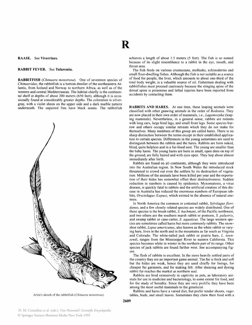
RABBITFISH (Chimaera monstrosa). One of seventeen species of Chimaeridae, the rabbitfish is a bottom dweller of the northeastern Atlantic, from Iceland and Norway to northern Africa, as well as of the western and central Mediterranean. The habitat chiefly is the continental shelf at depths of about 200 meters (650 feet) , although it is occasionally found at considerably greater depths. The coloration is silvergray, with a violet sheen on the upper side and a dark marble pattern underneath. The unpaired fins have black seams. The rabbitfish
Ani !' ketch of the rabbitfi h ( himaera monstrosa).
achieves a length of about 1.5 meters (5 feet). The fish is so named because of its slight resemblance to a rabbit in the eye, mouth, and throat area.
The fish feeds on various crustaceans, mollusks, echinoderms and small floor-dwelling fishes. Although the fish is not suitable as a source of food for people, the liver, which amounts to about one-third of the total body weight, is a valuable source of oil. Fishermen dealing with rabbitfishes must proceed cautiously because the stinging spine of the dorsal spine is poisonous and lethal injuries have been reported from accidents by contacting them.
RABBITS AND HARES. At one time, these leaping animals were classified with other gnawing animals in the order of Rodentia. They are now placed in their own order of mammals, i.e., Lagomorpha (leaping mammals). Nevertheless, in a general sense, rabbits are rodents with long ears, large hind legs, and small front legs. Some species burrow and others occupy similar retreats which they do not make for themselves. Many members of this group are called hares. There is no sharp distinction between the terms except in their established application to certain species. Differences in the young sometimes are used to distinguish between the rabbits and the hares. Rabbits are born naked, blind, quite helpless and in a fur-lined nest. The young are smaller than the baby hares. The young hares are born in small, open dens on top of the ground, are fully haired and with eyes open. They hop about almost immediately after birth.
Rabbits are found on all continents, although they were introduced into the Australian region. In New South Wales the introduced stock threatened to crowd out even the settlers by its destruction of vegetation. Millions of the animals have been killed per year and the exportation of their hides has somewhat offset their destructiveness. Sudden reduction in numbers is caused by epidemics. Myxomatosis, a virus disease, is quickly fatal to rabbits and the artif icial creation of this disease in Australia has reduced the enormous numbers of European rabbits, Oryctolagus (Lepus), which existed in the absence of natural enemies.
In North America the common or cottontail rabbit, Sylvilagus floridanus, and a few closely related species are widely distributed. One of these species is the brush rabbit, S. bachmani, of the Pacific northwest, and two others are the southern marsh rabbit or pontoon, S. palustris, and swamp rabbit or cane-cutter, S. aquaticus. The large western species are sometimes called hares but more commonly rabbits. The snowshoe rabbit, Lepus americanus, also known as the white rabbit or varying hare, lives in the north and in the mountains as far south as Virginia and Colorado. The white-tailed jack rabbit or prairie hare, L. townsendi, ranges from the Mississippi River to eastern California. This species becomes white in winter in the northern part of its range. Other species of jack rabbits are found farther west. See accompanying figure.
The flesh of rabbits is excellent. In the more heavily settled parts of the country they are an important game animal. The fur is thick and soft but the hides are weak, hence they are used chiefly for linings, for cheaper fur garments, and for making felt. After shearing and dyeing rabbit fur reaches the market as northern seal.
Rabbits are bred extensively in captivity as pets, as laboratory animals for use in medicine and bacteriology, to some extent for food, and for the study of heredity. Since they are very prolific they have been among the most useful mammals to the geneticist.
Rabbits and hares have a varied diet, but prefer tender shoots, vegetables, buds, and small leaves. Sometimes they chew their food with a
2609
© Springer Science+Business Media New York 1995D. M. Considine et al. (eds.), Van Nostrand’s Scientific Encyclopedia
2610 RABIES
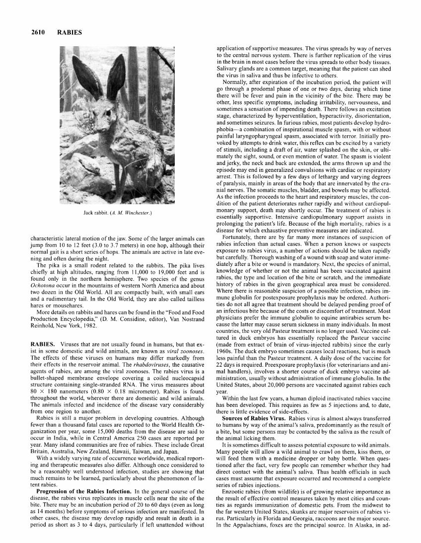
Jack rabbit. (A . M. Winchester.)
characteristic lateral motion of the jaw. Some of the larger animals can jump from 10 to 12 feet (3.0 to 3.7 meters) in one hop, although their normal gait is a short series of hops. The animals are active in late evening and often during the night.
The pika is a small rodent related to the rabbits. The pika lives chiefly at high altitudes, ranging from II ,000 to 19,000 feet and is found only in the northern hemisphere. Two species of the genus Ochotona occur in the mountains of western North America and about two dozen in the Old World. All are compactly built, with small ears and a rudimentary tail. In the Old World, they are also called tailless hares or mousehares.
More details on rabbits and hares can be found in the "Food and Food Production Encyclopedia," (D. M. Considine, editor), Van Nostrand Reinhold, New York, 1982.
RABIES. Viruses that are not usually found in humans, but that exist in some domestic and wild animals, are known as viral zoonoses. The effects of these viruses on humans may differ markedly from their effects in the reservoir animal. The rhabdoviruses, the causative agents of rabies, are among the viral zoonoses. The rabies virus is a bullet-shaped membrane envelope covering a coiled nucleocapsid structure containing single-stranded RNA. The virus measures about 80 X 180 nanometers (0 .80 X 0.18 micrometer) . Rabies is found throughout the world, wherever there are domestic and wild animals. The animals infected and incidence of the disease vary considerably from one region to another.
Rabies is still a major problem in developing countries. Although fewer than a thousand fatal cases are reported to the World Health Organization per year, some 15,000 deaths from the disease are said to occur in India, while in Central America 250 cases are reported per year. Many island communities are free of rabies. These include Great Britain, Australia, New Zealand, Hawaii, Taiwan, and Japan.
With a widely varying rate of occurrence worldwide, medical reporting and therapeutic measures also differ. Although once considered to be a reasonably well understood infection, studies are showing that much remains to be learned, particularly about the phenomenon of latent rabies.
Progression of the Rabies Infection. In the general course of the disease, the rabies virus replicates in muscle cells near the site of the bite. There may be an incubation period of 20 to 60 days (even as long as 14 months) before symptoms of serious infection are manifested. In other cases, the disease may develop rapidly and result in death in a period as short as 3 to 4 days, particularly if left unattended without
application of supportive measures . The virus spreads by way of nerves to the central nervous system. There is further replication of the virus in the brain in most cases before the virus spreads to other body tissues. Salivary glands are a common target, meaning that the patient can shed the virus in saliva and thus be infective to others.
Normally, after expiration of the incubation period, the patient will go through a prodomal phase of one or two days, during which time there will be fever and pain in the vicinity of the bite. There may be other, less specific symptoms, including irritability, nervousness, and sometimes a sensation of impending death . There follows an excitation stage, characterized by hyperventilation, hyperactivity, disorientation, and sometimes seizures . In furious rabies, most patients develop hydrophobia- a combination of inspirational muscle spasm, with or without painful laryngopharyngeal spasm, associated with terror. Initially provoked by attempts to drink water, this reflex can be excited by a variety of stimuli, including a draft of air, water splashed on the skin , or ultimately the sight, sound, or even mention of water. The spasm is violent and jerky, the neck and back are extended, the arms thrown up and the episode may end in generalized convulsions with cardiac or respiratory arrest. This is followed by a few days of lethargy and varying degrees of paralysis, mainly in areas of the body that are innervated by the cranial nerves. The somatic muscles, bladder, and bowels may be affected. As the infection proceeds to the heart and respiratory muscles, the condition of the patient deteriorates rather rapidly and without cardiopulmonary support, death may shortly occur. The treatment of rabies is essentially supportive . Intensive cardiopulmonary support assists in prolonging the patient's life. Because of the high mortality, rabies is a disease for which exhaustive preventive measures are indicated.
Fortunately, there are by far many more instances of suspicion of rabies infection than actual cases. When a person knows or suspects exposure to rabies virus, a number of actions should be taken rapidly but carefully. Thorough washing of a wound with soap and water immediately after a bite or wound is mandatory. Next, the species of animal, knowledge of whether or not the animal has been vaccinated against rabies, the type and location of the bite or scratch, and the immediate history of rabies in the given geographical area must be considered. Where there is reasonable suspicion of a possible infection , rabies immune globulin for postexposure prophylaxis may be ordered. Authorities do not all agree that treatment should be delayed pending proof of an infectious bite because of the costs or discomfort of treatment. Most physicians prefer the immune globulin to equine antirabies serum because the latter may cause serum sickness in many individuals. In most countries, the very old Pasteur treatment is no longer used. Vaccine cultured in duck embryos has essentially replaced the Pasteur vaccine (made from extract of brain of virus-injected rabbits) since the early 1960s. The duck embryo sometimes causes local reactions, but is much less painful than the Pasteur treatment. A daily dose of the vaccine for 22 days is required. Preexposure prophylaxis (for veterinarians and animal handlers), involves a shorter course of duck embryo vaccine administration, usually without administration of immune globulin. In the United States, about 20,000 persons are vaccinated against rabies each year.
Within the last few years, a human diploid inactivated rabies vaccine has been developed. This requires as few as 5 injections and, to date, there is little evidence of side-effects.
Sources of Rabies Virus. Rabies virus is almost always transferred to humans by way of the animal's saliva, predominantly as the result of a bite, but some persons may be contacted by the saliva as the result of the animal licking them.
It is sometimes difficult to assess potential exposure to wild animals. Many people will allow a wild animal to crawl on them, kiss them, or will feed them with a medicine dropper or baby bottle. When questioned after the fact, very few people can remember whether they had direct contact with the animal 's saliva. Thus health officials in such cases must assume that exposure occurred and recommend a complete series of rabies injections .
Enzootic rabies (from wildlife) is of growing relative importance as the result of effective control measures taken by most cities and counties as regards immunization of domestic pets. From the midwest to the far western United States, skunks are major reservoirs of rabies virus. Particularly in Florida and Georgia, raccoons are the major source. In the Appalachians, foxes are the principal source. In Alaska, in ad-
dition to the arctic fox, dogs, coyotes, wolves, and other carnivores that feed on fox carcasses are carriers of the rabies virus. In Europe, foxes are a major carrier of rabies virus among wildlife. Mongooses are a problem in Puerto Rico and Trinidad. Vampire bats, particularly as they infect cattle, are a major problem in Mexico. In Egypt, rabies in dogs, cats, and jackals is endemic. In India, jackals, in Iran, wolves, and in southeastern Asia and northern Africa, wild dogs are major rabies reservoirs.
Although dogs account for 90% of rabies cases, wild animals still account for thousands of cases worldwide each year. In the United States, skunks, raccoons, gray foxes, and Arctic and red foxes are the principal sources of rabies bites. For example, an epidemic of raccoon rabies has been progressing steadily up the East Coast from Florida since 1950 and by 1993 had worked its way north to eastern Pennsylvania. Skunks are found throughout the mid-continent, from Texas to the Dakotas and Montana. The skunk population of California is high, mainly along the coast and inland from Los Angeles north to the Oregon border. The gray fox population is more limited, affecting southeastern Arizona and central Texas. The population of the Arctic fox is found in the western half of Alaska and the extreme north of Maine.
During a period of over 30 years, scientists at the Centers of Disease Control in Atlanta have been researching self-vaccination methods for these wild animals. In 1970, Swiss researchers successfully placed baits in chicken heads. By 1985, machine-made baits of various composition found wide use in Europe and Canada and may be adopted on a wide scale in the United States. Attempts to launch widespread appeals to the Mexican population to immunize their pets have found some success.
Latent Rabies. In 1991, J. S. Smith (U.S. Centers for Disease Control, Atlanta, Georgia) and colleagues reported on studies of rabies viruses isolated from three individuals who had died from the disease and prior to their death had not revealed possible sources of their infections. All three patients had immigrated to the United States from Laos, the Philippines, and Mexico. The viral isolated in each case matched the antigenic or genetic characteristics of a rabies variant found in specimens from rabid animals obtained from or near the country in which the patient lived before immigrating to the United States. None of these variants were found among the isolates collected from rabid animals in the United States. Inasmuch as these patients had lived in the United States for nearly 5 years before onset of clinical mainfestations of rabies, the study panel assumed that rabies occurred after long incubation periods. Thus the findings emphasize the need for careful questioning of patients and their family members who have lived in areas outside the United States in which rabies is endemic. Evidently, rabies virus can persist for long periods without producing clinical signs.
In some countries where rabies is not endemic, it is common to postpone postexposure rabies treatment if the offending animal appears healthy at the time of the attack and can be observed and remains well for a period of I 0 days. This may be a relatively safe procedure in regions where rabies is not endemic, but it is hazardous in a country in which canine rabies is hyperendemic.
As pointed out by T. Hemachudha (Queen Saovabha Memorial Institute, Bankgkok, Thailand) and colleagues, "We have cared for one patient with rabies in whom treatment was delayed for five days while the animal responsible for the bite was being observed. The patient had the first signs of rabies two weeks after the start of treatment. Seven other patients with rabies received no treatment or only partial treatment after exposure, since the animals that bit them remained healthy for more than two weeks. Four dogs and one cat outlived the patients they bit. All the victims and their family members denied any other possible exposures to rabies. Unfortunately, none of these animals were available for study.
"Most animals that bite humans in Thailand are semidependent and semirestricted. Thus, observation of such animals is unlikely to be successful, and any attempt at observation only delays treatment. Furthermore, human rabies in Thailand is known for its short incubation periods, with the first symptoms developing in 71 percent of cases within one month. We therefore do not observe animals without first starting treatment of the patient with tissue-culture vaccine and equine or human rabies immune globulin where indicated. The vaccinations are dis-
RACCOONS (Mammalia, Carnivora) 2611
continued if the animal remains well after two weeks. By the end of the second week, the level of neutralizing antibody in the patient has reached an arbitrary protective level, providing protection against exposure in the future. We suggest that observing a dog or a cat that has bitten a person in a country such as Thailand may be considered a form of 'Siamese roulette."'
Reasons for Delaying Rabies Therapy. With numerous unknown factors pertaining to human rabies, notably its incubation period, some of the reasons given for a "waiting period" prior to commencing treatment include:
Exposure is seemingly insignificant, such as superficial bites by bats or other small mammals,
2 exposure to airborne particles (aerosols), 3 ignorance or fear of rabies treatment, 4 patient is too ill to be interviewed, thus ruling out important de
tails until it is too late, 5 in the case of latent rabies, the initial cause may have occurred
months or years before. Only recently has it been possible to make rapid clinical tests for the disease.
Additional Reading
Baer, G. M.: "The Natural History of Rabies," CRC Press, Boca Raton, Florida, 1991.
Kuwert, C., et al., Editors: "Rabies in the Tropics," Springer-Verlag, New York, 1985.
Metze, K., and W. Feiden: "Rabies Virus Ribonucleoprotein in the Heart," N Eng. J Med., 1814 (June 20, 1991).
Smith, J. S., et al.: "Unexplained Rabies in Three Immigrants in the United States," N Eng. J Med., 205 (January 24, 1991).
Staff: "Morbidit and Mortality Weekly Report," issued weekly by the Massachusetts Medical Society, Waltham, Massachusetts.
Winkler, W. G., and K. Bogel: "Control of Rabies in Wildlife," Sci. Amer., 86 (June 1992).
R. C. Vickery, M.D., D.Sc., Ph.D., Blanton/Dade City, Florida.
RACCOONS (Mammalia, Carnivora). These animals are of the family Procyonids, the organization of which is shown by the accompanying table. The most primitive procyonid species are the RingTailed Cats or Cacomistles (Bassariscus). Their total length ranges from 61.5 to 100 centimeters (24 to 39 inches), tail length from 31 to 53 centimeters (12 to 21 inches), and weight from 870 to 1300 grams (1.9 to 2.9 pounds). The head is flattened and has a long, tapered snout. The ears are large, oval, and thin, with well-developed pouches. The slender, graceful body is borne by short legs. The ringtailed cat walks in a semi-plantigrade manner; the heels of the feet have dense fur. The prominent head markings include the whitish lips, cheeks, and eyebrow regions, a small, dark spot on each side of the snout and in front of the base of the ears, the black nose, and the large eyes with their dark borders. The soft, rather 'long fur is tan on the upper side of the body, with brownish or brown hues as well, and in some spots even black. The underfur is lead-colored and the belly is
GENERAL ORGANIZATION OF THE RACCOONS (PROCYONIDS)
Ring-tailed cats or cacomistles (Bassariscus) North American ring-tailed cat (Bassariscus astutus) Central American ring-tailed cat (Bassariscus sumichrasti)
Olingos (Bassaricyon) Raccoon (Procyon)
North American raccoon (Procyon lotor) Guadalupe Islands raccoon (Procyon minor) Cozumel Island raccoon (Procyon pygamaeus) Crab-eating raccoon (Procyon cancrivorus)
Coatimundis (Nasua) White-nosed coati (Nasua narica) Nelson's coatimundi (Nasua nelsoni) Ring-tailed or red coati (Nasua nasua) Mountain coati (Nasua olivacea)
Kinkajou (Potos)
2612 RACCOONS (Mammalia, Carnivora)
whitish to whitish-brown. The black-and-white-banded tail is particularly striking; it is quite bushy. Including the black tip of the tail, there are seven to nine stripes in the tail; they are not closed on the underside of the tail. Modern species are barely distinguishable from the fossil forms found in the Upper Tertiary, and for this reason the ringtailed cat could be called a "living fossil."
Two species are distinguished: (I) North American Ring-Tailed Cat (Bassariscus astutus), with 14 subspecies; and (2) Central American Ring-Tailed Cat (Bassariscus sumichrasti), with 5 subspecies. The latter differs from the North American species in having dark brownish fur, a blackish snout and feet, slightly tapered ears, and rings which are not as distinct toward the tip of the tail. The claws are also different, being partially retractile in the North American species and completely nonretractile in the Centeral American ring-tailed cat.
The North American ring-tailed cat is distributed in southern Oregon, the southwestern U.S.A., and into Mexico (including Baja California) as far south as Veracruz and Oaxaca. The Central American species is found from southern Mexico southward to western Panama.
Both species live on small mammals, birds and their eggs, arthropods, and reptiles. Domestic poultry which roost in trees are sometimes taken as well. The plant material taken varies with season and location; the most common plant items include juniper berries, persimmons, wild plums, the fruits of the opuntia and saguaro cactus, wild figs, legumes, and fresh corn.
The Olingos are often confused with the kinkajous. Their total length is from 75 to 95 centimeters (29.5 to 37 inches), tail length from 40 to 48 centimeters (16 to 19 inches), and weigh from 970 to 1500 (2 to 3.3 pounds). The head is rounded but flattened on top, with small, rounded ears and a tapered snout. The eyes are fairly big; they protrude and have a cinammon-colored iris and a narrow, vertical pupil. The body is bony, with a very slender trunk and rather long limbs. The manner of walking is semi-plantigrade. The fingers and toes have sharp, greatly bent claws. Coloration of the long, loose hair is gray-brown with blackish hues on the upper side, and yellowish on the underside and insides of the limbs. A yellowish band extends across the neck to the base of the ears. The tail is very long, with fairly long hair, and 11 to 13 dark rings, often indistinct, which are not closed on the underside of the tail. Unlike the kinkajou's, their tail is not prehensile.
The olingo is distributed from northern Nicaragua across northwestern South America to Peru and northern Bolivia. The name "olingo" is a Panamanian word; in some regions it is known as cautaquil or cusacusa. It inhabits the tropical rainforest at an altitude of about 1800 meters (5905 feet). The species is not nearly as prevalent as the kinkajou, which inhabits the same ecological niche.
The olingo feeds chiefly on fruits but occasionally hunts insects and warm-blooded animals. Olingos are primarily nocturnal, living alone or in pairs, usually in treetops, and only rarely coming to the floor.
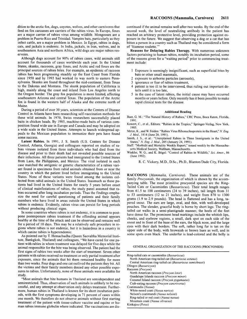
The procyonid family received its name from its most famous member, the Raccoon (Procyon). Its total length ranges from 60.3 to 105 centimeters (24 to 41 inches), tail length from 19.2 to 40.5 centimeters (7 .5 to 16 inches). Weight varies with species from 1.5 to 22 kilograms (3 .3 to 48.5 pounds). The head is broad, with a tapered snout and upright, rounded ears of medium size. The body looks plump with its long, thick fur. The legs are relatively long and have short hair and toes which can be spread greatly. The claws are long and sharp. The head has short fur, and a white-edged black "mask" extends from the cheeks across the eyes and snout, becoming somewhat lighter across the nose and running across the forehead in a thin band. The forehead and the sides of the snout and chin are white; the nose is black. The chief color is iron-gray, with yellow-brown and rust hues mixed into the region around the nape of the neck. The underside has short fur with white instead of black tips, and is not as thick as the fur on the upper side. Five to seven dark, narrow rings alternate with broader gray to light brown rings on the tail; the tip of the tail is always dark. See accompanying figure.
There are 7 species with 32 subspecies of raccoons, of which the Raccoon or North American Raccoon (Procyon lotor), with 25 subspecies, is the most familiar. There are 5 small species (Procyon insularis, Procyon maynardi, Procyon gloveralleni, Procyon minor and Procyon pygmaeus) which are found only on islands off Florida and Mexico. The South American Crab-Eating Raccoon (Procyon cancrivorus) has 5
subspecies distributed from Costa Rica and Panama across most of South America to northern Argentina. It differs from its northern relative in its coarser, thinner fur; the hair in the nape of the neck is directed forward. Since the crab-eating raccoon lacks underfur, it looks more slender and long-legged than the North American species. The claws are straighter, broader, and blunter; the lips, chin, and throat are graywhite, while the back is ash-gray to ochre or reddish with black tips on the fur.
Raccoons prefer forested terrain and stay in the vicinity of ponds, lakes, streams, and swamps; they also occur in mangrove forests along subtropical and tropical coastal plains, and on the edges of savannas and semi-arid regions as long as they have an ample water supply. Raccoons are not found at altitudes above 2500 meters (8202 feet), in pure evergreen forests, or in arid regions lacking water.
The diet of the raccoon changes with the season, and raccoons make very good use of what is available at a particular time. Animal prey includes insects, young small mammals, earthworms, crustaceans, snails, mussels, reptiles (especially their eggs), amphibians, and fishes. Birds are less often taken. In swampy regions and long fresh-water lagoons, raccoons take young muskrats from their nest, and in some areas this has almost led to the disappearance ofthese rodents. Plant materials comprise over half the annual diet component in the North American raccoon; it feeds on wild fruit, berries, grasses, leaves, rinds, beechnuts, and similar foods. This raccoon also feeds in stands of young corn, melons, sweet potatoes, young sugar cane, and fruit. In Canada and the northern U.S.A., where the raccoon endures varying periods of cold weather in a semihibernation state, it builds up a fat store from the great supply of acorns. During the winter the raccoon loses up to 50% of its fall weight. The crab-eating raccoon, as its common name indicates, has a much more specialized diet. Its molar teeth are broader and have prominent ridges which are better suited for masticating tough material.
Raccoons move across land at a slow amble, with the head lowered, back arched, and tail dangling downward. They can run at a gallop for short time, and reach a maximum speed of 24 kilometers per hour (15 miles per hour). Trees are climbed at the normal pace or even at this gallop. Raccoons are solitary. If two feeding competitors meet, they threaten each other by growling and lowering the head, baring their teeth, and laying their ears back. The fur of the nape of the neck and the shoulders becomes erect. This bluff usually has the desired effect of frightening both of them away from each other, and generally no fight ensues. Individual territories overlap considerably and they are de-
fended by their owners (and thus in the truest sense should not strictly be considered as territories). The raccoon population density in a particular area is dependent upon the food supply, the number of trees suitable for nests, and predation pressure.
Raccoons are chiefly nocturnal animals. They climb readily and usually nest in hollow trees. In some sections of the United States, coon hunting at night with specially bred and trained dogs is regarded as a sport. Raccoon fur is among the better grades, although not the finest or most beautiful. It is used in making coats.
The Coatimundis (Nasua) have two very striking characteristics: (I) a moveable, trunklike snout, which protrudes beyond the lower jaw, and (2) a long, vertically carried tail. Their length is from 74 to 134 centimeters (29 to 53 inches), including a tail length from 36 to 68 centimeters (14 to 27 inches); they weigh from 3 to 6 kilograms (6.5 to 13 pounds). The head is long. The ears are rounded, short, and hidden within the fur. The fur on the head and legs is short; elsewhere on the body it is thick and coarse. It is quite stiff but has underfur which is woolly and curly. Coloration varies considerably from cinnamon-brown or reddish-brown to brown gray. In one animal it may even change with successive molts! A group of coatimundis may contain both dark and light individuals; coloration differences are also independent of sex and age. The coloration on the under side is yellowish to dark brown. There is a face mask. The forehead and top of the head are yellowish-gray; the lips in North and Central American specimens are white. There is a whitish spot above and behind the eye and at the base of the long whiskers. A stripe extends along both sides of the nose from the eyes to the tip of the nose. The snout, chin and throat are whitish-yellow, and the insides ofthe ears are pale yellow. The paws are dark brown to blackish. The claws on the hand are long, powerful, blunt, and slightly curved, while those on the feet are short, greatly arched, and very sharp. The tail generally has an indistinct ringed marking.
Four species with seventeen subspecies are distinguished: (I) The White-Nosed Coati (Nasua narica), which generally has a light color, comprises three subspecies distributed from the southwestern U.S.A. to Panama. (2) Nelson's Coatimundi (Nasua nelsoni), a much smaller species with shorter, softer, silkier fur and smaller teeth, is found on the island of Cozumel off the Mexican province of Quintana Roo. (3) The Ring-Tailed or Red Coati (Nasua nasua), with eleven subspecies (which are difficult to distinguish), is found as far south as Argentina and along coastal plains up to altitudes of3000 meters (9843 feet). (4) The Mountain Coati (Nasua olivacea) is another small species, with a slender head, long snout, and small, short-crowned, sharp-ridged teeth. Its coloration is olive-brown to rust-brown, with blackish underfur in specimens from Colombia and Venezuela but whitish underfur in specimens from Ecuador. Its tail is yellowish-gray and has black rings. Distribution is in the mountain forests and their clearings in western Venezuela and the Colombian-Ecuadorian Andes from 2, 700 to 3, I 00 meters (8858 to 10,171 feet).
Within this great range, the coatimundis have a highly adaptable nature, living in tropical lowlands, dry, high-altitude forests, in oak forests, mesquite grassland, and even on the edges of forests. During the last few decades, the white-nosed coati has penetrated further into the U.S.A. and has become a stable part of the animal life in southern Arizona, southwestern New Mexico, and southwestern Texas.
Coatimundis feed chiefly on invertebrates but also prey on lizards and small rodents; birds are caught infrequently. Like the raccoon, the coatimundi rolls its prey under the thick soles of its forefeet. This quickly kills prey which bite and sting, and the rolling process also removes harmful spines and other chitinous parts. Vertebrates are pressed to the ground with the paws and are killed by a bite to the head. The coatimundi eats large fruits, scraping the meat of the fruit out with the claws.
The Kinkajou (Potos jlavus) is the only member of its genus. It differs from all the other raccoonlike species by its prehensile tail. Length is from 81 to 113 centimeters (32 to 44 inches), of which tail length is from 39.5 to 55.5 centimeters (15.5 to 22 inches). Weight ranges from 1.8 to 4.6 kilograms ( 4 to I 0 pounds). The head is round, the ears short and round. The snout is blunt. The protruding eyes have chestnut-brown irises and round pupils. The trunk is long and the limbs are short. The fingers and toes are covered with membrane for one-third of their length. They have curved, sharp claws. The soles, like those of the olingo, are short and thickly covered with hair. The tail is about the same
RADAR 2613
length as the body length; it is round in cross section and uniformly covered with short hair, and tapers toward the tip. The fur is very thick, soft, short, and gleaming. The upper side of the body is olive-brown, yellowish-brown, or reddish-brown to sandy, often covered with a bronze sheen. The middle of the back is darker, and the underside is yellow-brown, light tea-colored, or even golden-yellow. There are fourteen subspecies of the kinkajous; they differ in skull and tooth characteristics, coloration, and body size.
The kinkajou feeds chiefly on plant materials, primarily fruits such as wild figs, zapote, guava, avocado, and mango. It also takes softshelled nuts and legumes; insects are eaten less often. The narrow, greatly extensible tongue is used to pull out the soft fruit meat and to lick nectar, insects, and the honey of wild bees. The kinkajou often eats bird eggs and sometimes eats young birds as well. During the day the kinkajou sleeps in a coiled position on its side; the front feet cover the eyes. It sleeps in a tree hollow or in a thick, cool network of leaves and vmes.
RACE RUNNER (Reptilia, Sauria). Slender lizards, reaching a length of about I 0 inches, including the long tapering tail. They are found throughout the United States with the exception of the most northern part. One species is known as the swift, Cnemidophorus sexlineatus.
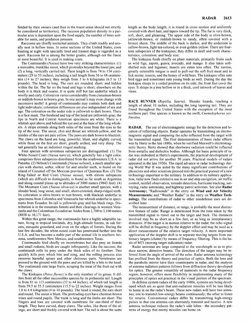
RADAR. The use of electromagnetic energy for the detection and location of reflecting objects. Radar operates by transmitting an electromagnetic signal and comparing the echo reflected from the target with the transmitted signal. The first demonstration of basic radar effects was by Hertz in the late 1880s, when he verified Maxwell's electromagnetic theory. Hertz showed that shortwave radiation could be reflected from metallic and dielectric bodies. Although the basic principle of radar was embodied in Hertz's experiments, the practical development of radar did not arrive for another 50 years. Practical models of radars appeared in the late 1930s. The rapid advance in radar technology during World War II was aided by the many significant contributions of physicists and other scientists pressed into the practical pursuit of a new technology important to the military. In addition to its military application, radar now finds extensive use in air and ship navigation, air traffic control, rainfall observation, tornado detection, hurricane tracking, surveying, radar astronomy, and highway patrol activities. See also Radar Astronomy; "Radiosonde" in the entry on Wind and Air Velocity Measurements; and "Weather Radar" in the entry on Weather Technology. The contributions of radar to other nondefense uses are described later.
The measurement of distance, or range, is probably the most distinctive feature of radar. Range is determined from the time taken by the transmitted signal to travel out to the target and back. The distances involved may be as short as a few feet, or as long as interplanetary distances. If the target is in motion relative to the radar, the echo signal will be shifted in frequency by the doppler effect and may be used as a direct measurement of the relative target velocity. A more important application of the doppler shift is to separate moving targets from stationary targets (clutter) by means offrequency filtering. This is the basis of MTI (moving target indication) radar.
Radar antennas are large compared to the wavelength so as to produce narrow, directive beams. The direction of the target may be inferred from the angle of arrival of the echo. Radar antenna technology has profited from the theory and practice of optics. Both the lens and the parabolic mirror have their counterparts in radar, and the analysis of antenna radiation patterns follows from diffraction theory developed for optics. The greater versatility of materials in the radar frequency region, however, offers more flexibility in implementing many of the principles of optics not practical in the visual portion of the spectrum.
In defense system radars of the early 1980s, systems are being developed which are so quiet that anti-radiation missiles will be less likely to home in on the radar's beam. These new radars will have two antennas, one to transmit low-energy beams continuously; the other to listen for returns. Conventional radars differ by transmitting high-energy pulses so that one antenna can alternately transmit and receive. A new antenna technique reduces the radar's side lobes-the secondary patterns of energy that enemy missiles can home on.
2614 RADAR
The external appearance of a radar is dominated by the antenna. Most radars use some form of parabolic reflector. The radar antenna can also be a fixed array of many small radiating elements (perhaps several thousand) operating in unison to produce the desired radiation characteristics. Array antennas have the advantage of greater flexibility and more rapid beam steering than mechanically-steered reflector antennas because the beam movement can be accomplished by electrically changing the relative phase at each element of the antenna. High power can be radiated since a separate transmitter can be applied at each element. The flexibility and speed of an array antenna make it necessary in some instances to control its functions and analyze its output by automatic data processing equipment rather than more simple formats involving display tubes.
Two obstacles to the advent of phased array radars-high cost and weight-are being overcome with innovations in technology and manufacturing. Tiny diode phase shifters now operate on the same power as their bulkier ferrite counterparts. The many wires that required individual connections and testing are giving way to thick-film fabrication, in which circuits are silkscreened onto aluminum wafers. It is now possible to place radiators, phase shifters, and power dividers onto single substrates-building blocks that can be assembled into larger sections before undergoing initial tests.
Radars are generally found within the microwave portion of the electromagnetic spectrum, typically from about 200 MHz ( 1.5 meters wavelength) to about 35,000 MHz (8.5 millimeters wavelength). These are not firm bounds. Some radars operate outside these limits. The wellknown British CH radar system of World War II, which provided warning of air attack, operated in the high-frequency region in the vicinity of 25 MHz. Experimental radars have been demonstrated in the millimeter wavelength region where small physical apertures are capable of narrow beam widths and good angular resolution. Radar principles, of course, have been applied at optical frequencies with lasers for the measurement of range and detection of small motions, using the doppler effect.
The detection performance of a radar system is specified by the radar equation which states:
P,G I P =--XuX--XA
rec 41TR2 4'1TR2
( R . d (Power Density) ( Target ) ~~~~~ ) = at a Distance X Backscatt~r
R Cross Sectwn
( Space ) ( Antenna )
X Attenuation on X Collecting Return Path Area
where P, is the transmitted power; G is the transmitting antenna gain; R is the range; u is the backscatter cross section; and A is the effective receiving aperture of the antenna. The wavelength A. of the radar signal does not appear explicitly in this expression, but it can be introduced by the relationship between the gain and effective receiving area of an antenna which states:
The detection capability and the measurement accuracy of a radar are ultimately limited by noise. The noise may be generated within the radar receiver itself, or it may be external and enter the receiver via the antenna, along with the desired signal. External noise is generally small at microwave frequences, but it can be a significant part of the overall noise iflow-noise receiving devices, such as the maser and the parametric amplifier are used.
Since the effects of noise must be considered in statistical terms, the analysis and understanding of the basic properties of radar have benefited from the application of the mathematical theory of statistics. The statistical theory of hypothesis testing has been applied to the radar detection problem where it is necessary to determine which of two hypotheses is correct: The output of a radar receiver is due to (1) noise alone, or (2) signal plus noise. One of the results is the quantitative specification of the signal-to-noise ratio required at the receiver for reliable detection. Also derived from hypothesis testing based on the like-
lihood ratio or a posteriori probability are concepts for ideal detection methods with which to compare the performance of practical receivers. The statistical theory of parameter estimation has also been applied with success to analyze the accuracy and theoretical limits of radar measurements.
Reliable detection of targets requires signal-to-noise power ratios of the order of 10 to I 00 at the receiver, depending upon the degree of error that can be tolerated in making the decision as to the presence or absence of a target. Even larger values are generally needed for the accurate measurement of target parameters. Although these values may seem high, for comparison, the minimum signal-to-noise ratio of quality television signals is usually of the order of I 0,000.
The rms error o Tin measuring the time delay to the target and back (range measurement) can be expressed as:
where 13 is defined as the effective signal bandwidth; E is the total energy of the received signal; and N0 is the noise power per unit cycle of bandwidth assuming the noise has a uniform spectrum over the bandwidth of the receiver. The square of 13 is equal to (2TI)2 times the second central moment of the power spectrum normalized with respect to the signal energy. For a simple rectangular pulse, E/N0 is approximately equal to the signal-to-noise (power) ratio. To obtain an accurate range measurement, EIN0 and the signal bandwidth must be large. A similar expression applies to the accuracy of the measurement of doppler frequency if the rms time delay error is replaced by the rms frequency error and the effective bandwidth is replaced by the etTective time duration of the signal. Thus, the longer the signal duration and the greater the ratio EIN0 , the more accurate is the doppler frequency measurement. Likewise, the angular measurement accuracy also depends on the ratio E/N0 and the effective aperture size.
In addition to noise, radar can be limited by the presence of unwanted interfering echoes from large nearby objects, such as the surface of the ground, trees, vegetation, sea waves, and weather. Although these "clutter" echoes may be troublesome in some applications, they are sometimes echoes of interest, as, for example, in ground mapping and meteorological applications.
Radar as Catalyst of Technological Progress. In 1940, the Radiation Laboratory (Massachusetts Institute of Technology) was established to investigate microwave frequencies for radar. Scientists were agreeably surprised to find that the usable frequency spectrum could be extended by some three orders of magnitude. Power sources were developed that were capable of delivering several magawatts of power at 3,000 megahertz and kilowatts up to 24,000 megahertz. It was found that good radar resolution required equipment with bandwidths of several megahertz as contrasted with the few kilohertz required for voice radio circuits. A whole technology was required to build servomechanisms for driving highly precise and large engineering structures. Also required were improved pulse techniques and cathode ray tubes and delay line storage devices for operation with the early electronic computers. New concepts in circuitry and components were required, several of which made television practical just a few years later. In the late 1940s, the western world was threatened by a new kind of attack from the Soviet Block, which exploded its first atomic device in 1948. This caused a vitally renewed interest in radar and associated technology, which had cooled a bit after the close of World War II. Particularly targeted among the new interests were effective means for coupling radar with the rapidly developing digital computer technology of that period. Radar developments, in turn, accelerated computer technology in a sort of technological symbiosis.
Great interest was shown in developing radars that could detect lowflying aircraft. A solution proposed at that time involved the use oflarge numbers of radars operating in concert and yielding both high-and lowaltitude surveillance information. So much data frorP such systems required data analyzers in the form of computer systems. In the late 1940s, the Massachusetts Institute of Technology built the MIT Whirlwind, the first reliable and fast computer designed for real-time usage. Air defense equipment at that time had not been transistorized, but it turned out that the application required the speed and reliability only obtainable with transistors. These, however, did not become available
until the early 19 50s. Later developments include a core memory ( 1955). The British were also having similar problems in updating their radar nets. Missile guidance systems placed a new load on radar technology, as did later needs for satellite-tracking radars. The needs of radar also catalyzed the development of modern signal-processing techniques, including pulse compression and matched filtering, as well as the development of acoustic wave technology and charge-coupled devices. Radar developments led to several nondefense uses, such as radio and radar astronomy, microwave spectroscopy, and the instrument technology required for earth resource meteorological, and navigational satellites. See Satellites (Scientific and Reconnaissance).
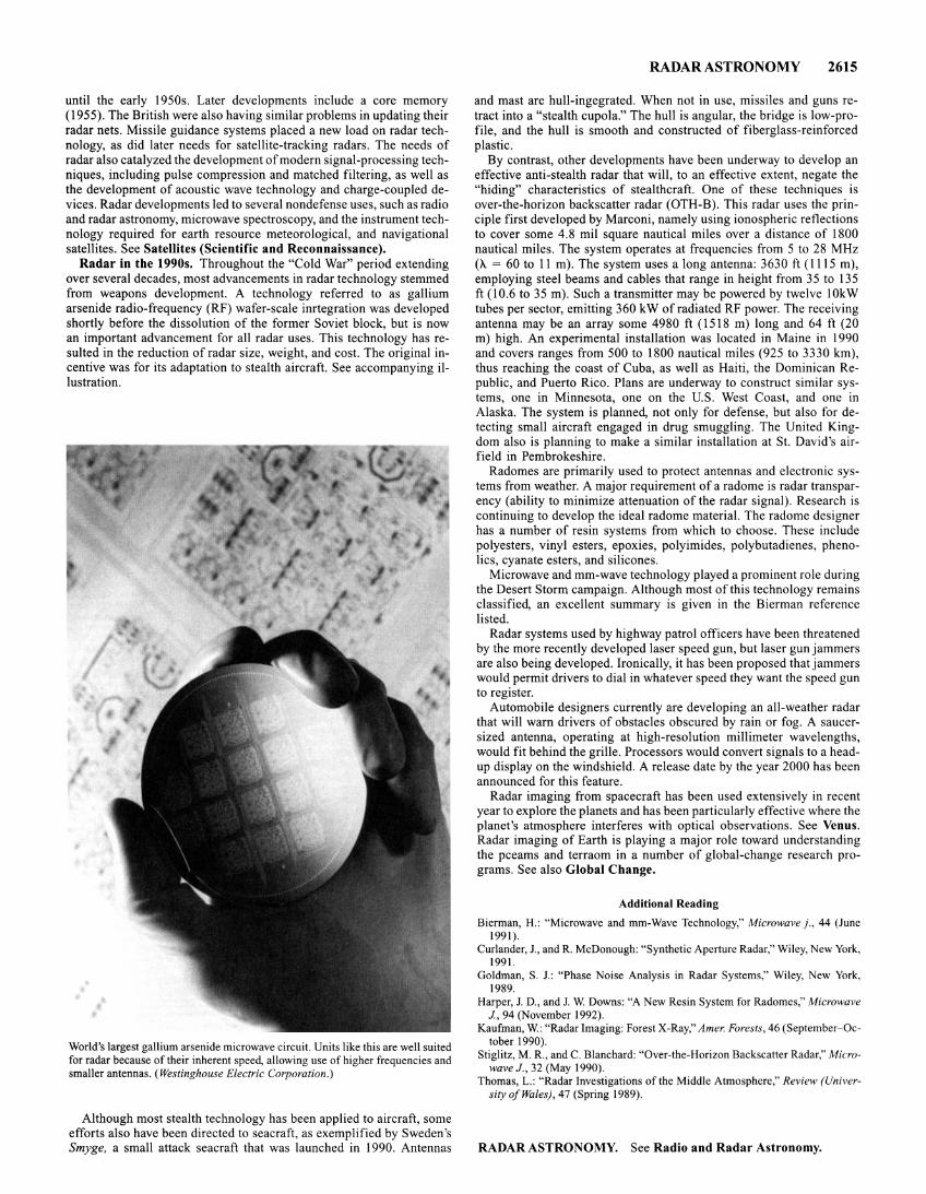
Radar in the 1990s. Throughout the "Cold War" period extending over several decades, most advancements in radar technology stemmed from weapons development. A technology referred to as gallium arsenide radio-frequency (RF) wafer-scale inrtegration was developed shortly before the dissolution of the former Soviet block, but is now an important advancement for all radar uses. This technology has resulted in the reduction of radar size, weight, and cost. The original incentive was for its adaptation to stealth aircraft. See accompanying illustration.
World's largest gallium arsenide microwave circuit. Units like this are well suited for radar because of their inherent speed, allowing use of higher frequencies and smaller antennas. (Westinghouse Electric Corporation.)
Although most stealth technology has been applied to aircraft, some efforts also have been directed to seacraft, as exemplified by Sweden's Smyge, a small attack seacraft that was launched in 1990. Antennas
RADAR ASTRONOMY 2615
and mast are hull-ingegrated. When not in use, missiles and guns retract into a "stealth cupola." The hull is angular, the bridge is low-profile, and the hull is smooth and constructed of fiberglass-reinforced plastic.
By contrast, other developments have been underway to develop an effective anti-stealth radar that will, to an effective extent, negate the "hiding" characteristics of stealthcraft. One of these techniques is over-the-horizon backscatter radar (OTH-B). This radar uses the principle first developed by Marconi, namely using ionospheric reflections to cover some 4.8 mil square nautical miles over a distance of 1800 nautical miles. The system operates at frequencies from 5 to 28 MHz (A. = 60 to II m). The system uses a long antenna: 3630 ft ( 1115 m), employing steel beams and cables that range in height from 35 to 135 ft (10.6 to 35m). Such a transmitter may be powered by twelve !OkW tubes per sector, emitting 360 kW of radiated RF power. The receiving antenna may be an array some 4980 ft ( 1518 m) long and 64 ft (20 m) high. An experimental installation was located in Maine in 1990 and covers ranges from 500 to 1800 nautical miles (925 to 3330 km), thus reaching the coast of Cuba, as well as Haiti, the Dominican Republic, and Puerto Rico. Plans are underway to construct similar systems, one in Minnesota, one on the U.S. West Coast, and one in Alaska. The system is planned, not only for defense, but also for detecting small aircraft engaged in drug smuggling. The United Kingdom also is planning to make a similar installation at St. David's airfield in Pembrokeshire.
Radomes are primarily used to protect antennas and electronic systems from weather. A major requirement of a radome is radar transparency (ability to minimize attenuation of the radar signal). Research is continuing to develop the ideal radome material. The radome designer has a number of resin systems from which to choose. These include polyesters, vinyl esters, epoxies, polyimides, polybutadienes, phenolics, cyanate esters, and silicones.
Microwave and mm-wave technology played a prominent role during the Desert Storm campaign. Although most of this technology remains classified, an excellent summary is given in the Bierman reference listed.
Radar systems used by highway patrol officers have been threatened by the more recently developed laser speed gun, but laser gun jammers are also being developed. Ironically, it has been proposed that jammers would permit drivers to dial in whatever speed they want the speed gun to register.
Automobile designers currently are developing an all-weather radar that will warn drivers of obstacles obscured by rain or fog. A saucersized antenna, operating at high-resolution millimeter wavelengths, would fit behind the grille. Processors would convert signals to a headup display on the windshield. A release date by the year 2000 has been announced for this feature.
Radar imaging from spacecraft has been used extensively in recent year to explore the planets and has been particularly effective where the planet's atmosphere interferes with optical observations. See Venus. Radar imaging of Earth is playing a major role toward understanding the pceams and terraom in a number of global-change research programs. See also Global Change.
Additional Reading
Bierman, H.: "Microwave and mm-Wave Technology," Microwave)., 44 (June 1991).
Curlander, J. , and R. McDonough: "Synthetic Aperture Radar," Wiley, New York, 1991.
Goldman, S. J.: "Phase Noise Analysis in Radar Systems," Wiley, New York, 1989.
Harper, J. D., and J. W. Downs: "A New Resin System for Radomes," Microwave J., 94 (November 1992).
Kaufman, W.: "Radar Imaging: Forest X-Ray," A mer. Forests, 46 (September-October 1990).
Stiglitz, M. R., and C. Blanchard: "Over-the-Horizon Backscatter Radar," Microwave J., 32 (May 1990).
Thomas, L.: "Radar Investigations of the Middle Atmosphere," Review (University of Wales), 47 (Spring 1989).
RADAR ASTRONOMY. See Radio and Radar Astronomy.
2616 RADIAL DISTRIBUTION FUNCTION
RADIAL DISTRIBUTION FUNCTION. The radial distribution function for a liquid is defined as the function p(r) where 4Tir2p(r) dr is the average number of molecules with centers at distances between r and r + dr from some selected molecule. If the liquid is isotropic it is the average number density at distance r from the selected molecule. The radial distribution function may be computed from measurements of x-ray diffraction patterns and it is of central importance in the kinetic theory of liquids.
RADIAL VELOCITY (Star). That component of the space motion of a star that is directed toward the sun is known as the radial velocity of the star, or the velocity of the star in the line of sight. It is measured by spectroscopic methods, employing the Doppler-Fizeau principle, and is determined directly in linear units (i.e. , kilometers per second, or miles per second).
Since a comparison spectrum must be available for measurement of the Doppler displacement of the stellar spectral lines, a slit spectrograph must be used for an accurate determination of radial velocity. This instrument is wasteful of light, and only one star can be observed at a time . For these reasons, the number of stars for which accurate radial velocities are known is small relative to the total number of stars. The objective prism may be used to determine approximate radial velocities for a large number of stars. In one of the applications of this instrument, a comparison spectrum is obtained by interposing a neodymium screen between the prism and the photographic plate. This produces a few absorption lines on the stellar spectrum relative to which the stellar lines themselves may be measured. Another application of the objective prism to this problem utilizes the fact that the Doppler displacement for a line in the red is greater than that for a line in the violet. Hence, the length of the spectrum between these extremes will be changed by an amount proportional to the radial velocity. Although the results obtained by the use of the objective prism are only approximate, they may be used for statistical study of stellar motions.
From a study of the variations in radial velocity of certain stars, known as spectroscopic binaries, the relative orbits of these objects may be determined. Since the first order relation
fl.A v
A c
(where A is the local rest wavelength, fl.A is the observed shift, vis the frequency and cis the velocity of light) does not differentiate between motion of the source and the observer, one must correct for the revolution and rotation of the earth and, in many cases, for the space motion of the sun.
See also Spectroscopic Binaries.
RADIANT HEATING. See Infrared Radiation.
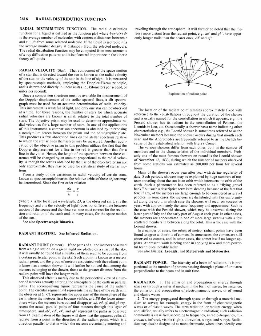
RADIANT POINT (Meteor). If the paths of all the meteors observed from a single station on a given night are plotted on a chart of the sky, it will usually be found that a number of them seem to be coming from a certain particular point in the sky. Such a point is known as a meteor radiant point, and the group of meteors associated with the radiant point is known as a meteor shower. It will further be noticed that, among the meteors belonging to the shower, those at the greater distance from the radiant point will have the longer trails.
This observed effect is merely due to the perspective view of a number of meteors actually entering the atmosphere of the earth in parallel paths. The accompanying figure represents the cause of the radiant point. The circular segment AA represents the surface of the earth with the observer at 0; CC represents the upper part of the atmosphere of the earth where the meteors first become visible, and BB the lower atmosphere where the meteors burn out and disappear; ab, cd, ef, and gh represent the actual parallel paths of four meteors through this layer of atmosphere, and ab' , cd', ef , and gh' represent the paths as observed from 0. Examination of the figure will show that the apparent paths all radiate from a point in the direction R, the radiant point, which is a direction parallel to that in which the meteors are actually entering and
traveling through the atmosphere. It will further be noted that the meteors more distant from the radiant point, e.g. , ab' and gh ' , have apparently longer trails than the nearer ones, cd' and ef'.
Explanation of radiant point.
The location of the radiant point remains approximately fixed with reference to the constellations throughout the duration of the shower and is usually named for the constellation in which it appears; e.g. , the Perseid shower has its radiant in the constellation of Perseus, the Leonids in Leo, etc. Occasionally, a shower has a name indicating other characteristics; e.g., the Leonid shower is sometimes referred to as the November meteors because the shower occurs during that month each year, and the Andromedes are frequently referred to as the Bielids because of their established relation with Biela's Comet.
The various showers differ from each other, both in the number of members and in the characteristics of the individual members. Probably one of the most famous showers on record is the Leonid shower of November 12, 1833 , during which the number of meteors observed from some stations was estimated as 200,000 per hour for several hours.
Many of the showers occur year after year with define regularity of date. Such periodic showers may be explained by huge numbers of meteors traveling about the sun in an orbit which intersects the orbit of the earth . Such a phenomenon has been referred to as a "flying gravel bank ," but such a descriptive term is misleading because of the fact that few, if any, of the meteors are large enough to be considered as gravel pebbles. In some cases, the meteors are distributed with fair uniformity all along the orbit, in which case the showers will recur on successive years with approximately the same frequency and appearance. Such is the case with the Perseid shower, which may be observed during the latter part of July and the early part of August each year. In other cases, the meteors are concentrated in one or more large swarms with a few scattered members in between along the orbit. This is the case with the Leonid shower.
In a number of cases, the orbits of meteor radiant points have been found to agree with orbits of comets. In some cases, the comets are still observed as comets, and in other cases, the comet itself no longer appears . At present, work is being done in applying new and more powerful techniques, notably radar.
See also Bielids; Leonids; and Meteoroids and Meteorites.
RADIANT POWER. The intensity of a beam of radiation. It is proportional to the number of photons passing through a plane of unit area perpendicular to the beam and in unit time.
RADIATION. I. The emission and propagation of energy through space or through a material medium in the form of waves; for instance, the emission and propagation of electromagnetic waves, or of sound and elastic waves .
2. The energy propagated through space or through a material medium as waves ; for example, energy in the form of electromagnetic waves or of elastic waves . The term radiation, or radiant energy, when unqualified, usually refers to electromagnetic radiation; such radiation commonly is classified, according to frequency, as radio-frequency, microwave, infrared, visible (light) , ultraviolet, x-rays, and-y-rays. Radiation may also be designated as monochromatic, when it has, ideally, one
wavelength, or actually a narrow band of wavelengths; or as heterogeneous, when it has two or more narrow bands of wavelengths (or particles of two or more narrow energy ranges); or as homogeneous, when it has only one narrow band of wavelengths (or consists of essentially monoenergetic particles).
3. Corpuscular emissions, such as alpha- and beta-radiation or rays of mixed or unknown type.
See also Electromagnetic Phenomena.
RADIATIONAL COOLING. In meteorology, the cooling of the earth's surface and adjacent air, accomplished (mainly at night) whenever the earth's surface suffers a net loss of heat due to terrestrial radiation. See also Atmosphere (Earth).
RADIATION FOG. See Fog and Fog Clearing.
RADIATION FORMULA (Planck). See Planck Radiation Formula.
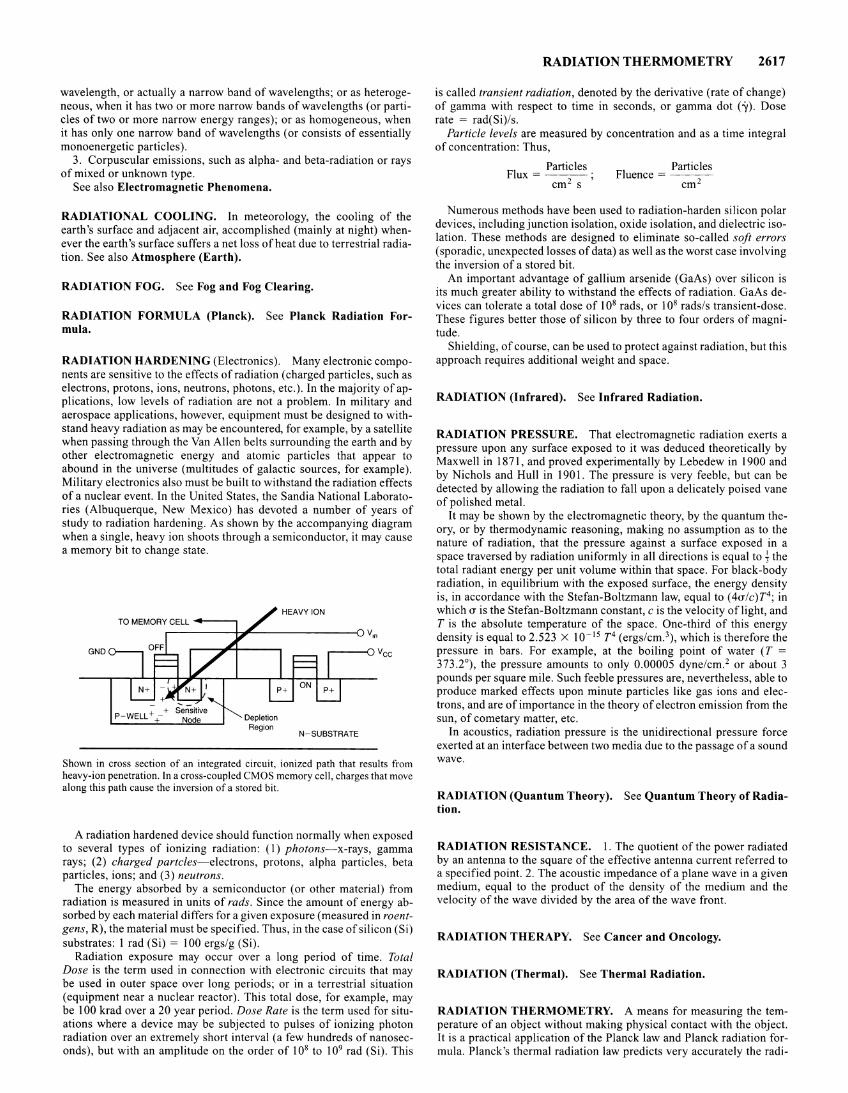
RADIATION HARDENING (Electronics). Many electronic components are sensitive to the effects of radiation (charged particles, such as electrons, protons, ions, neutrons, photons, etc.). In the majority of applications, low levels of radiation are not a problem. In military and aerospace applications, however, equipment must be designed to withstand heavy radiation as may be encountered, for example, by a satellite when passing through the Van Allen belts surrounding the earth and by other electromagnetic energy and atomic particles that appear to abound in the universe (multitudes of galactic sources, for example). Military electronics also must be built to withstand the radiation effects of a nuclear event. In the United States, the Sandia National Laboratories (Albuquerque, New Mexico) has devoted a number of years of study to radiation hardening. As shown by the accompanying diagram when a single, heavy ion shoots through a semiconductor, it may cause a memory bit to change state.
GND
N-SUBSTRATE
Shown in cross section of an integrated circuit, ionized path that results from heavy-ion penetration. In a cross-coupled CMOS memory cell, charges that move along this path cause the inversion of a stored bit.
A radiation hardened device should function normally when exposed to several types of ionizing radiation: (I) photons-x-rays, gamma rays; (2) charged partcles-electrons, protons, alpha particles, beta particles, ions; and (3) neutrons.
The energy absorbed by a semiconductor (or other material) from radiation is measured in units of rads. Since the amount of energy absorbed by each material differs for a given exposure (measured in roentgens, R), the material must be specified. Thus, in the case of silicon (Si) substrates: 1 rad (Si) = 100 ergs/g (Si).
Radiation exposure may occur over a long period of time. Total Dose is the term used in connection with electronic circuits that may be used in outer space over long periods; or in a terrestrial situation (equipment near a nuclear reactor). This total dose, for example, may be 100 krad over a 20 year period. Dose Rate is the term used for situations where a device may be subjected to pulses of ionizing photon radiation over an extremely short interval (a few hundreds of nanoseconds), but with an amplitude on the order of 108 to 109 rad (Si). This
RADIATION THERMOMETRY 2617
is called transient radiation, denoted by the derivative (rate of change) of gamma with respect to time in seconds, or gamma dot (')!). Dose rate = rad(Si)/s.
Particle levels are measured by concentration and as a time integral of concentration: Thus,
I Particles F ux = ·
cm 2 s ' Particles
Fluence = ---cm2
Numerous methods have been used to radiation-harden silicon polar devices, including junction isolation, oxide isolation, and dielectric isolation. These methods are designed to eliminate so-called soft errors (sporadic, unexpected losses of data) as well as the worst case involving the inversion of a stored bit.
An important advantage of gallium arsenide (GaAs) over silicon is its much greater ability to withstand the effects of radiation. GaAs devices can tolerate a total dose of 108 rads, or 108 rads/s transient-dose. These figures better those of silicon by three to four orders of magnitude.
Shielding, of course, can be used to protect against radiation, but this approach requires additional weight and space.
RADIATION (Infrared). See Infrared Radiation.
RADIATION PRESSURE. That electromagnetic radiation exerts a pressure upon any surface exposed to it was deduced theoretically by Maxwell in 1871, and proved experimentally by Lebedew in 1900 and by Nichols and Hull in 1901. The pressure is very feeble, but can be detected by allowing the radiation to fall upon a delicately poised vane of polished metal.
It may be shown by the electromagnetic theory, by the quantum theory, or by thermodynamic reasoning, making no assumption as to the nature of radiation, that the pressure against a surface exposed in a space traversed by radiation uniformly in all directions is equal to~ the total radiant energy per unit volume within that space. For black-body radiation, in equilibrium with the exposed surface, the energy density is, in accordance with the Stefan-Boltzmann law, equal to ( 4u/c)T4 ; in which u is the Stefan-Boltzmann constant, cis the velocity oflight, and T is the absolute temperature of the space. One-third of this energy density is equal to 2.523 X 10- 15 T4 (ergs/cm. 3), which is therefore the pressure in bars. For example, at the boiling point of water (T = 373.2°), the pressure amounts to only 0.00005 dyne/cm.2 or about 3 pounds per square mile. Such feeble pressures are, nevertheless, able to produce marked effects upon minute particles like gas ions and electrons, and are of importance in the theory of electron emission from the sun, of cometary matter, etc.
In acoustics, radiation pressure is the unidirectional pressure force exerted at an interface between two media due to the passage of a sound wave.
RADIATION (Quantum Theory). See Quantum Theory of Radiation.
RADIATION RESISTANCE. 1. The quotient of the power radiated by an antenna to the square of the effective antenna current referred to a specified point. 2. The acoustic impedance of a plane wave in a given medium, equal to the product of the density of the medium and the velocity of the wave divided by the area of the wave front.
RADIATION THERAPY. See Cancer and Oncology.
RADIATION (Thermal). See Thermal Radiation.
RADIATION THERMOMETRY. A means for measuring the temperature of an object without making physical contact with the object. It is a practical application of the Planck law and Planck radiation formula. Planck's thermal radiation law predicts very accurately the radi-
2618 RADIATION THERMOMETRY
ant power emitted per unit area per unit wavelength by a blackbody, or complete radiator. It can be written
h( _ cl 1 -3 M f...,T)- IS eC,I~<T -1 W. m
where C1 = 2-rrhC2 = 3.7415 X 10 16 W·m2 is called the first radiation constant
C2 = Ch/k = 1.43879 X 10⁻² m·k is the second radiation constant
Advantages of the Method. In radiation thermometry, the sensor does not have to be in thermal equilibrium with the object. Thus, very high temperatures can be measured. Planck's radiation law is the basis for the International Practical Temperature Scale of 1968 (IPTS-68) at temperatures above the gold point (1 064.43°C). The realization of the temperature scale above the gold point with carefully designed meterological instruments, while virtually without upper limit, is possible to within a precision of :±: 0.01 °C or better. But radiation thermometry is not limited to high temperatures. Modern instruments are commercially available that can measure well below -l8°C (0°F). Typical industrial precision lies in the range of:±: 0.5 to 1% of absolute temperature.
Advantages and limitations of radiation thermometry are summarized in Table 1 . Because of the wide selection of instruments offered, determining the best suited instrument for a given application can be difficult. Two of the major criteria are (1) wavelength response, and (2) target size. Speed of response also may be a primary factor in selection. Factors which also contribute to difficulty of selection include lack of standards and precise terminology. Critical parameters of waveband, target size or field of view and calibration uncertainty are not always stated explicitly in the commercial literature.
TABLE I. RELATIVE ADVANTAGES AND LIMITATIONS OF RADIATION THERMOMETERS
Can measure: very high temperatures moving objects large areas
Advantages
inside vacuum or pressure vessels inside semi-transparent objects
Does not contact (hence mar) object of measurement Instrument not physically exposed to temperature it measures (as are devices
which require physical contact) Rapid response High differential sensitivity
Relatively high cost: initial installation requires maintenance
Limitations and Disadvantages
Application engineering required to solve some problems No uniform calibration tables
Perspective. Early radiation thermometers, called radiation and optical pyrometers, were radically different from one another both in design and use. The simple radiation pyrometer was compact, designed for fixed installation, and served as a transducer only. In contrast, the portable optical pyrometer was a complete measuring system and a much more sophisticated instrument. Developments in integrated circuits, transducer or detector devices, and optical technology have had a profound impact on both fixed and portable instrument design.
Types of Radiation Thermometers
A convenient classification of commercial radiation thermometers IS:
1. Wideband instruments 2. Narrowband instruments 3. Ratio (two-color) thermometers 4. Optical pyrometers 5. Fiber optic instruments
Both portable and fixed-installation instruments are available in each class. See Table 2.
TABLE 2. PRINCIPAL TYPES OF COMMERCIAL RADIATION
THERMOMETERS
Type Temperature Range, °C
Wideband fixed l-4000 portable 0-2000
Narrowband fixed -50-2500 portable 0-2500
Ratio (two color) fixed 1000-2500 portable
Optical fixed 800-2500 portable 800-2500
Fiber optic fixed 100-2500 portable 250-800
Wideband Instruments. These are the simplest and least expensive of the radiation thermometers. They are available for responding to radiation with wavelengths from 0.3 J.Lm to between 2.5 and 20 J.Lm, depending upon lens or window material used. These instruments also are called broadband or total radiation pyrometers because of their relatively wide wavelength response and the fact that they measure a significant fraction of the total radiation emitted by the object of measurement. Historically, these devices were the earliest fixed or automatic units. They still find wide application. The characteristics of four specific commercial instruments are given in Table 3.
TABLE 3. CHARACTERISTICS OF FOUR GENERAL-PURPOSE WIDEBAND
RADIATION THERMOMETERS
Temperature Range Limits, °C
500-1800 600-1900
0-1000 825-1800
Waveband Limits fLM
0.4-2.6 0.4-2.6
7-20 0.4-2.6
Narrowband Instruments. These instruments usually have a carefully selected, relatively narrow wavelength response, often selected to meet the requirements of a very specific application. The detector, lens, window, and filter(s) are selected to provide the particular wavelength response desired. Optical pyrometers can be considered a subset of this class. See Table 4. See also Fig. 1.
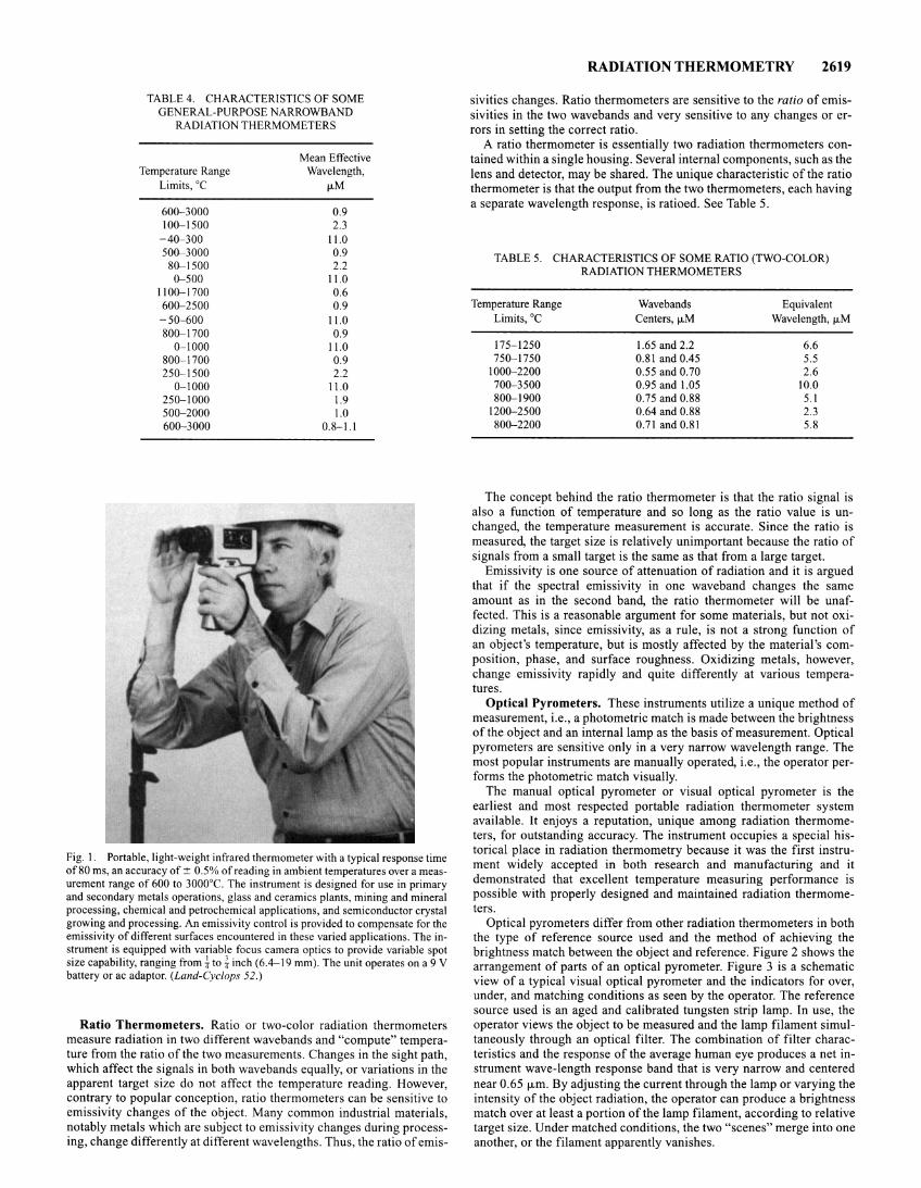
TABLE 4. CHARACTERISTICS OF SOME GENERAL-PURPOSE NARROWBAND
RADIATION THERMOMETERS
Temperature Range Limits, °C
600-3000 100-1500
- 40- 300 500-3000
80- 1500 0- 500
1100- 1700 600-2500 -50-600 800-1700
0-1000 800-1700 250-1500
0- 1000 250- 1000 500- 2000 600-3000
Mean Effective Wavelength,
J.LM
0.9 2.3
11.0 0.9 2.2
11.0 0.6 0.9
11.0 0.9
11.0 0.9 2.2
11.0 1.9 1.0
0.8-1.1
Fig. I. Portable, light-weight infrared thermometer with a typical response time of 80 ms, an accuracy of::':: 0.5% of reading in ambient temperatures over a measurement range of 600 to 3000°C. The instrument is designed for use in primary and secondary metals operations, glass and ceramics plants, mining and mineral processing, chemical and petrochemical applications, and semiconductor crystal growing and processing. An emissivity control is provided to compensate for the emissivity of different surfaces encountered in these varied applications. The instrument is equipped with variable focus camera optics to provide variable spot size capability, ranging from {to i inch (6.4-19 mm). The unit operates on a 9 V battery or ac adaptor. (Land-Cyclops 52.)
Ratio Thermometers. Ratio or two-color radiation thermometers measure radiation in two different wavebands and "compute" temperature from the ratio of the two measurements. Changes in the sight path, which affect the signals in both wavebands equally, or variations in the apparent target size do not affect the temperature reading. However, contrary to popular conception, ratio thermometers can be sensitive to emissivity changes of the object. Many common industrial materials, notably metals which are subject to emissivity changes during processing, change differently at different wavelengths. Thus, the ratio of emis-
RADIATION THERMOMETRY 2619
sivities changes. Ratio thermometers are sensitive to the ratio of emissivities in the two wavebands and very sensitive to any changes or errors in setting the correct ratio.
A ratio thermometer is essentially two radiation thermometers contained within a single housing. Several internal components, such as the lens and detector, may be shared. The unique characteristic of the ratio thermometer is that the output from the two thermometers, each having a separate wavelength response, is ratioed. See Table 5.
TABLE 5. CHARACTERISTICS OF SOME RATIO (TWO-COLOR) RADIATION THERMOMETERS
Temperature Range Wavebands Equivalent Limits, oc Centers, J.LM Wavelength, J.LM
175-1250 1.65 and 2.2 6.6 750-1750 0.81 and 0.45 5.5
1000-2200 0.55 and 0.70 2.6 700-3500 0.95 and 1.05 10.0 800- 1900 0.75 and 0.88 5.1
1200- 2500 0.64 and 0.88 2.3 800-2200 0.71 and 0.81 5.8
The concept behind the ratio thermometer is that the ratio signal is also a function of temperature and so long as the ratio value is unchanged, the temperature measurement is accurate. Since the ratio is measured, the target size is relatively unimportant because the ratio of signals from a small target is the same as that from a large target.
Emissivity is one source of attenuation of radiation and it is argued that if the spectral emissivity in one waveband changes the same amount as in the second band, the ratio thermometer will be unaffected. This is a reasonable argument for some materials, but not oxidizing metals, since emissivity, as a rule, is not a strong function of an object's temperature, but is mostly affected by the material's composition, phase, and surface roughness. Oxidizing metals, however, change emissivity rapidly and quite differently at various temperatures.
Optical Pyrometers. These instruments utilize a unique method of measurement, i.e., a photometric match is made between the brightness of the object and an internal lamp as the basis of measurement. Optical pyrometers are sensitive only in a very narrow wavelength range. The most popular instruments are manually operated, i.e., the operator performs the photometric match visually.
The manual optical pyrometer or visual optical pyrometer is the earliest and most respected portable radiation thermometer system available. lt enjoys a reputation, unique among radiation thermometers, for outstanding accuracy. The instrument occupies a special historical place in radiation thermometry because it was the first instrument widely accepted in both research and manufacturing and it demonstrated that excellent temperature measuring performance is possible with properly designed and maintained radiation thermometers.
Optical pyrometers differ from other radiation thermometers in both the type of reference source used and the method of achieving the brightness match between the object and reference. Figure 2 shows the arrangement of parts of an optical pyrometer. Figure 3 is a schematic view of a typical visual optical pyrometer and the indicators for over, under, and matching conditions as seen by the operator. The reference source used is an aged and calibrated tungsten strip lamp. In use, the operator views the object to be measured and the lamp filament simultaneously through an optical filter. The combination of filter characteristics and the response of the average human eye produces a net instrument wave-length response band that is very narrow and centered near 0.65 jLm. By adjusting the current through the lamp or varying the intensity of the object radiation, the operator can produce a brightness match over at least a portion of the lamp filament, according to relative target size. Under matched conditions, the two "scenes" merge into one another, or the filament apparently vanishes.
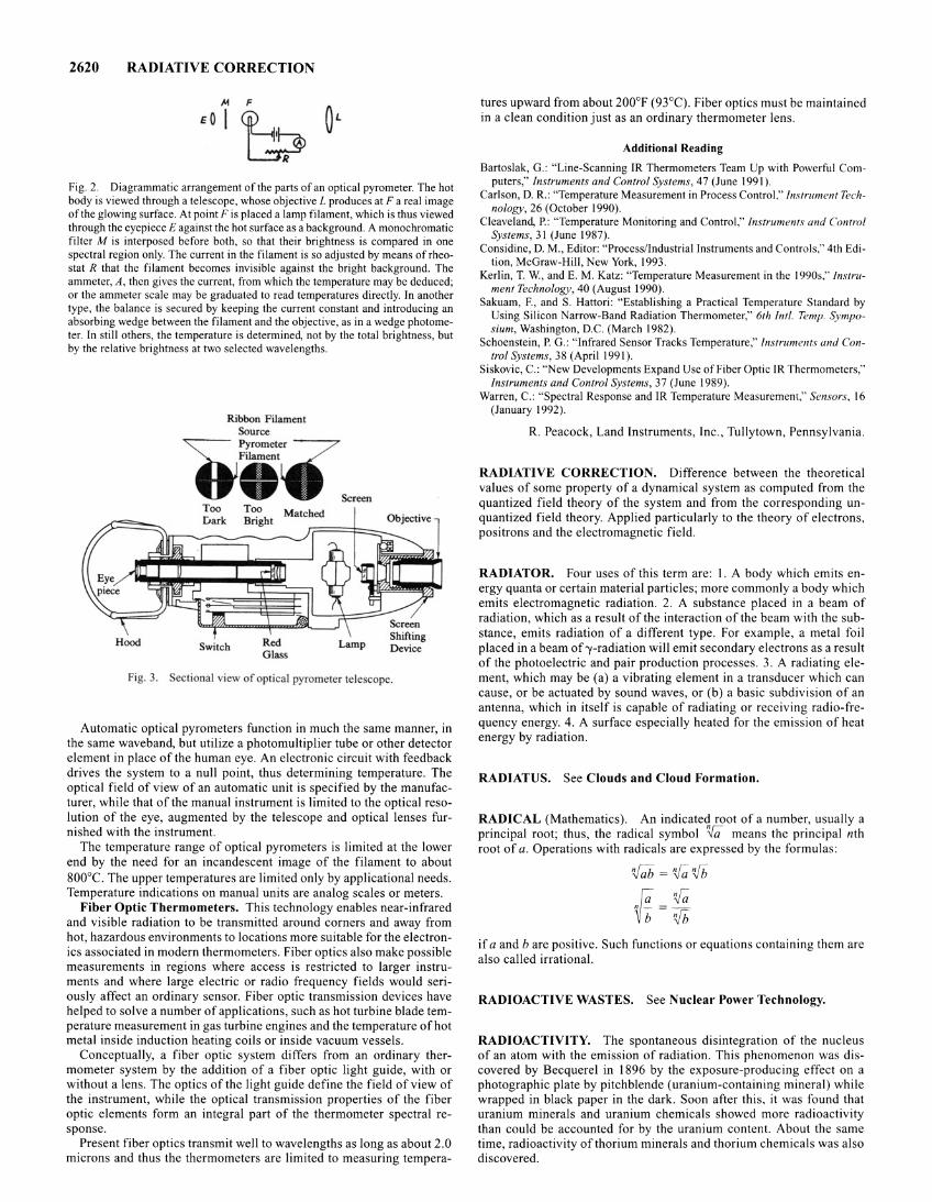
2620 RADIATIVE CORRECTION
F
b. Fig. 2. Diagrammatic arrangement of the parts of an optical pyrometer. The hot body is viewed through a telescope, whose objective L produces at Fa real image of the glowing surface. At point F is placed a lamp filament, which is thus viewed through the eyepiece E against the hot surface as a background. A monochromatic filter M is interposed before both, so that their brightness is compared in one spectral region only. The current in the filament is so adjusted by means of rheostat R that the filament becomes invisible against the bright background. The ammeter, A, then gives the current, from which the temperature may be deduced; or the ammeter scale may be graduated to read temperatures directly. In another type, the balance is secured by keeping the current constant and introducing an absorbing wedge between the filament and the objective, as in a wedge photometer. In still others, the temperature is determined, not by the total brightness, but by the relative brightness at two selected wavelengths.
Hood Switch Red Glass
Lamp
Fig. 3. Sectional view of optical pyrometer tete cope.
Automatic optical pyrometers function in much the same manner, in the same waveband, but utilize a photomultiplier tube or other detector element in place of the human eye. An electronic circuit with feedback drives the system to a null point, thus determining temperature. The optical field of view of an automatic unit is specified by the manufacturer, while that of the manual instrument is limited to the optical resolution of the eye, augmented by the telescope and optical lenses furnished with the instrument.
The temperature range of optical pyrometers is limited at the lower end by the need for an incandescent image of the filament to about 800°C. The upper temperatures are limited only by applicational needs. Temperature indications on manual units are analog scales or meters.
Fiber Optic Thermometers. This technology enables near-infrared and visible radiation to be transmitted around corners and away from hot, hazardous environments to locations more suitable for the electronics associated in modern thermometers. Fiber optics also make possible measurements in regions where access is restricted to larger instruments and where large electric or radio frequency fields would seriously affect an ordinary sensor. Fiber optic transmission devices have helped to solve a number of applications, such as hot turbine blade temperature measurement in gas turbine engines and the temperature of hot metal inside induction heating coils or inside vacuum vessels.
Conceptually, a fiber optic system differs from an ordinary thermometer system by the addition of a fiber optic light guide, with or without a lens. The optics of the light guide define the field of view of the instrument, while the optical transmission properties of the fiber optic elements form an integral part of the thermometer spectral response.
Present fiber optics transmit well to wavelengths as long as about 2.0 microns and thus the thermometers are limited to measuring tempera-
tures upward from about 200°F (93°C). Fiber optics must be maintained in a clean condition just as an ordinary thermometer lens.
Additional Reading
Bartoslak, G.: "Line-Scanning IR Thermometers Team Up with Powerful Computers," Instruments and Control Systems, 47 (June 1991 ).
Carlson, D. R. : "Temperature Measurement in Process Control," Instrument Technology, 26 (October 1990).
Cleaveland, P.: "Temperature Monitoring and Control,'' Instruments and Control Systems, 31 (June 1987).
Considine, D. M., Editor: "Process/Industrial Instruments and Controls," 4th Edition, McGraw-Hill, New York, 1993.
Kerlin, T. W., and E. M. Katz: "Temperature Measurement in the 1990s," Instrument Technology, 40 (August 1990).
Sakuam, F., and S. Hattori: "Establishing a Practical Temperature Standard by Using Silicon Narrow-Band Radiation Thermometer," 6th Inti. Temp. Symposium, Washington, D.C. (March 1982).
Schoenstein, P. G.: "Infrared Sensor Tracks Temperature," lnstrum<:nts and Control Systems, 38 (Aprill991).
Siskovic, C.: "New Developments Expand Use of Fiber Optic IR Thermometers," Instruments and Control Systems, 37 (June 1989).
Warren, C.: "Spectral Response and IR Temperature Measurement," Sensors, 16 (January 1992).
R. Peacock, Land Instruments, Inc., Tullytown, Pennsylvania.
RADIATIVE CORRECTION. Difference between the theoretical values of some property of a dynamical system as computed from the quantized field theory of the system and from the corresponding unquantized field theory. Applied particularly to the theory of electrons, positrons and the electromagnetic field.
RADIATOR. Four uses of this term are: I. A body which emits energy quanta or certain material particles; more commonly a body which emits electromagnetic radiation. 2. A substance placed in a beam of radiation, which as a result of the interaction of the beam with the substance, emits radiation of a different type. For example, a metal foil placed in a beam of'Y-radiation will emit secondary electrons as a result of the photoelectric and pair production processes. 3. A radiating element, which may be (a) a vibrating element in a transducer which can cause, or be actuated by sound waves, or (b) a basic subdivision of an antenna, which in itself is capable of radiating or receiving radio-frequency energy. 4. A surface especially heated for the emission of heat energy by radiation.
RADIATUS. See Clouds and Cloud Formation.
RADICAL (Mathematics). An indicated root of a number, usually a principal root; thus, the radical symbol '!.Ia means the principal nth root of a. Operations with radicals are expressed by the formulas:
v;;b = if; rifh
~=~ if a and b are positive. Such functions or equations containing them are also called irrational.
RADIOACTIVE WASTES. See Nuclear Power Technology.
RADIOACTIVITY. The spontaneous disintegration of the nucleus of an atom with the emission of radiation. This phenomenon was discovered by Becquerel in 1896 by the exposure-producing effect on a photographic plate by pitchblende (uranium-containing mineral) while wrapped in black paper in the dark. Soon after this, it was found that uranium minerals and uranium chemicals showed more radioactivity than could be accounted for by the uranium content. About the same time, radioactivity of thorium minerals and thorium chemicals was also discovered.
The excess radioactivity of mineral over chemical uranium led Pierre and Marie Curie to experiment with the mineral. To detect the presence of radioactivity the discharge of a charged gold-leaf electroscope was used. A quantitative estimation ofthe amount of radioactivity was made by observing the rate of drop of the gold leaf. By chemically separating the uranium mineral into fractions and examining each fraction by the electroscope, they found in the bismuth element fraction the first new radioactive element to be discovered. It was named polonium ( 1898). They found that polonium disappeared rapidly, half of its radioactivity vanishing in about six months. The fraction containing barium element was also found by them to be radioactive. Repeated fractional crystallizations of the chloride and bromide solutions made possible the recovery by them of practically pure salt of the second new radioactive element. It was named radium ( 1898).
Radium is chemically similar to barium; it displays a characteristics optical spectrum; its salts exhibit phosphorescence in the dark, a continual evolution of heat taking place sufficient in amount to raise the temperature of I 00 times its own weight of water I ac every hour; and many remarkable physical and physiological changes have been produced. Radium shows radioactivity a million times greater than an equal weight of uranium and, unlike polonium, suffers no measurable loss of radioactivity over a short period of time (its half life is 1620 years). From solutions of radium salts, there is separable a radioactive gas; radium emanation, radon, which is a chemically inert gas similar to xenon and disintegrates with a half life of 3.82 days, with the simultaneous formation of another radioactive element, Radium A (polonium-218).
Definitions 1
Decay. The dimunution of a radioactive substance due to nuclear emission of alpha or beta particles, gamma rays or positrons.
Decay Constant. A constant A. that relates the instant rate of radioactive decay of a radioactive species to the number of atoms N present at a given time t:
-(oNIIJ) = A.N
Where N is the number of atoms present at time zero:
N = N 0 e->-1
Decay Product. A nuclide that results from the radioactive disintegration of a radionuclide that is formed either directly or as the result of progressive transformations in a radioactive series. The nuclide thus
produced is sometimes called the daughter or daughter element. Half-Life (Radioactive Element) The average time required for
one-half of the atoms in a sample of radioactive element to decay. The half-life ti is given by
t,_ = (In 2)/A. 2
Types of Radioactivity
Beginning in 1899 and continuing through the next two decades, E. Rutherford and his associates conducted a rather thorough study of the radiations emitted by radioactive substances. During this study the radiations were found to be of three types, called alpha, beta, and gamma radiations. In kind, they resemble anode rays, cathode rays, and x-rays, respectively. In this behavior toward electrical and magnetic fields, the resemblance is qualitatively complete: (1) Alpha rays are positively charged particles of mass number 4 and slightly deflected by electrical and magnetic fields. (2) Beta rays are negatively charged electrons, and strongly deflected by electrical and magnetic fields. (3) Gamma rays are undeflected by electrical and magnetic fields, and of wavelength of the order of 10- 8 to 10-9 centimeters.
Alpha Ray Emission. Alpha rays have a definite velocity and a definite range for each radioactive nuclide. The velocity is from 5-7% that of light. Range is defined as the distance traversed in a homogeneous medium before absorption. The penetrating power of alpha rays is
1 Data pertaining to radioisotopes is provided in quantitative detail in the "Handbook of Chemistry and Physics," 73rd Edition, CRC Press, Boca Raton, Florida, 1992-1993.
RADIOACTIVITY 2621
the smallest of the three kinds of rays, the beta rays being of the order of I 00 times, and the gamma rays I 0,000 more penetrating. The alpha rays are twice-ionized nuclei of helium (He2+). Ramsay and Royds (1909) experimentally demonstrated that accumulated alpha particles, quite independently of the matter from which they have been expelled, consist of helium. They sealed radon in a glass tube with a wall so thin that the alpha particles passed through the wall into a surrounding vessel and after six days the optical spectrum of helium was observed. Helium itself does not diffuse through such a wall. Therefore, alpha particles on losing their positive charge become ordinary helium. This is the first instance of the production of a known element during radioactive transformation. The loss of a single alpha particle by an atom leaves the residual atom four units less in mass number, and two units less in atomic number. The shooting of alpha particles was visibly registered by Crooke's spinthariscope in which the tip of a wire, coated by a tiny amount of radium salts, was placed near a screen coated with zinc blende. Viewed in the dark with a magnifying eyepiece, each alpha particle striking the zinc blende target was observed to produce a visible scintillation. The detection and counting of single alpha particles was accomplished by Rutherford and Geiger (1908), by the deflection of an electrometer needle upon the arrival of each alpha particle in a gas at low pressure in an electric field somewhat below the sparking point.
Beta Radiation. Beta rays are electrons. They have varying velocities almost up to that of light. The loss of a single negatron by an atom leaves the residual atomic nucleus the same in mass number and one unit greater in atomic number, while the loss of a positron or an orbital electron capture leaves the residual atomic nucleus the same in mass number, and one unit less in atomic number.
Double-Beta Decay. In a scholarly paper, M. Moe (University of California, Irvine) and S. Rosen (Los Alamos National Laboratory) describe what is considered to be a very rare radioactive event, namely that of double-beta decay. Searching since 1971, Moe and colleagues observed a double-beta event directly in 1987. In an event of this type, using a selenium atom, which contains 48 neutrons and 34 protons, as an example, two of the neutrons decay simultaneously into two protons. During the process, two beta rays and two antineutrinos are generated. Application of an external magnetic field will cause the paths of the ejected electrons to spiral, but in different directions. A double spiral of this type, when observed, is indicative of a double-beta event. The atom remaining has gained two additional protons and lost two neutrons, as compared with its original state (i.e., prior to the double-beta decay event). The selenium has been transformed to krypton.
The neutrino problem is described in the article on Particles (Subatomic). The double-beta decay event may contribute to the solution of that problem. In their introductory to the aforementioned article, the authors observe, "The future of fundamental theories that account for everything from the building blocks of the atom to the architecture of the cosmos hinges on studies of this rarest of all observed radioactive events."
Gamma Radiation. Gamma rays are photons of electromagnetic radiation. This radiation is much more penetrating than alpha or beta particles. The presence of gamma rays from 30 milligrams of radium can be observed in an electroscope after passing through 30 centimeters of iron (Rutherford). For the protection of the operator, radium is kept in lead outer containers or screened by lead sheets.
The naturally occurring radioactive elements at the upper end of the periodic table of elements form a number of series, the elements of each series existing in radioactive equilibrium, unless individual elements are separated chemically away from the series. These series include the Uranium Series, the Thorium Series, and the Actinium Series. See Tables I, 2, and 3. These arrangements are useful in showing the decaychain (i.e., the parent-daughter) relationships of radioactive elements, including such concepts as radioactive equilibrium. Other naturally occurring radioactive elements also exist, including, for example, 4°K, 87Rb, and 148Sm.
Ionizing Radiation. This type of radiation is of major importance because it represents a biological and environmental hazard. Radioactive isotopes contribute to this potential danger. The extent of damage varies immensely with the dose (exposure over a long or short period of time) and with the source material. The principal ionizing radiations are summarized in Table 4.
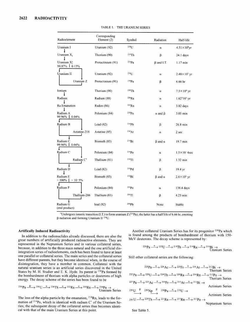
2622 RADIOACTIVITY
TABLE I. THE URANIUM SERIES
Corresponding Radioelement Element (2) Symbol Radiation Half-life
Uranium I Uranium (92) 238U a 4.51 X 10⁹yr l
Uranium X 1 Thorium (90) 2l4Th 13 24.1 days
l Uranium x; Protactinium (91) 234pa 13 and I.T. 1.17 min 99.87% I o.I3%
l
1 Uranium II Uranium (92) 2J4U a 2.48X 10⁵ yr
I Uranium Z Protactinium (91) 2J•pa 13 6.66 hr I
Ionium
l Thorium (90) zJoTh a 7.5Xl04 yr
Radium Radium (88) 226Ra a 1.623 I 03 yr
l Ra Emanation Radon (86) "'Rn a 3.82 days
l Radium A Polonium (84) 21sp0 a and 13 3.05 min 99.96% I o.o4%
l
1 Radium B Lead (82) 214pb 13 26.8 min
I Astatine-218 Astatine (85) 218At a 2 sec I
' RadiumC Bismuth (83) 214Bi 13 and a 19.7 min 99.96% I o.o4%
l
1 Radium C Polonium (84) z14p0 a 1.5X I0-4sec
I Radium C" Thallium (81) 210TJ 13 1.32 min I
' Radium D Lead (82) 210pd 13 19.4 yr
l Radium E Bismuth (83) ''"Bi 13 and a 2.6X 10⁶ yr - IOO% I - 10-5%
l
1 Radium F Polonium (84) 210Po a 138.4 days
I Thallium-206 Thallium (81) 206TJ 13 4.23 min I
' Radium G lead (82) 206pb None Stable (end product)
·undergoes ism eric transition (I. T.) to form uranium Z (234Pa); the latter has a halflife of 6.66 hr, emitting 13 radiation and forming Uranium II 234U.
Artifically Induced Radioactivity In addition to the radionuclides already discussed, there are also the
great numbers of artificially produced radioactive elements. They are represented in the Neptunium Series and in various collateral series, because, in addition to the three main natural and the one artificial disintegration series of radioelements, each has been found to have at least one parallel or collateral series. The main series and the collateral series have different parents, but they become identical when, in the course of disintegration, they have a member in common. Collateral with the natural uranium series is an artificial series discovered in the United States by M. H. Studier and E. K. Hyde. Its parent is 230Pa formed by the bombardment of thorium with alpha particles or deuterons of high energy. The decay scheme of the series has been found to be
23opa ~ 230U ~ 226Th ~ 222Ra ~ 21sRn ~ 2t4p0 ~ Uranium Series
The loss of the alpha particle by the emanation, 218Rn, leads to the formation of 214Po, which is identical with radium C' of the Uranium Series; the subsequent decay of the collateral series thus becomes identical with that of the main Uranium Series at this point.
Another collateral Uranium Series has for its progenitor 226Pa which is found among the products of bombardment of thorium with 150-MeV deuterons. The decay scheme is represented by:
226pa~ mu ~ 2I8Th~2I4Ra~ 21oBi ~ Uranium Series
Still other collateral series are the following:
228pa~224Ac~ 220fr~ 2I6At~ 2I2Bi ~ Thorium Series
232pa ~ mu ~ 224Th ~ 220Ra ~ 2I6Rn ~ mp0 ~ Thorium Series
Actinium Series 239U ~ 239Np f3 239Pu ~ mu ~ ~ ~ Actinium Series
239 u~zzsTh~22IRa~2I7Rn~mp0 ~
Neptunium Series
See Table 5.
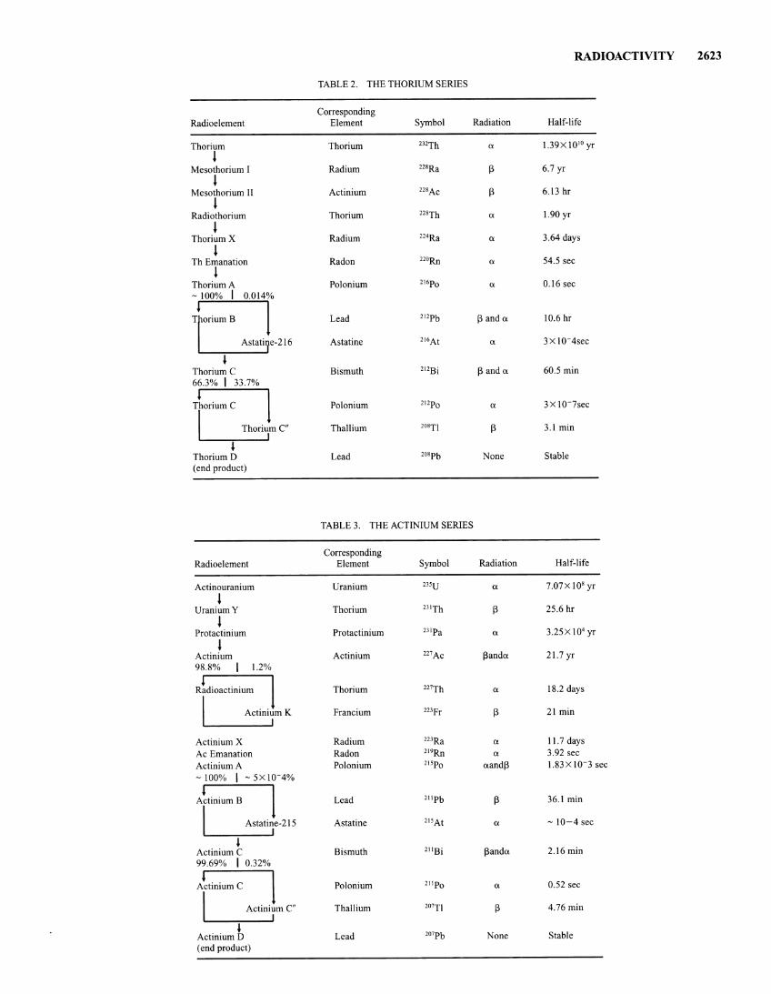
RADIOACTIVITY 2623
TABLE2. THE THORIUM SERIES
Corresponding Radioelement Element Symbol Radiation Half-life
Thorium Thorium 232Th a 1.39X 10 10 yr
l Mesothorium I Radium 22sRa [3 6.7 yr
l Mesothorium 11 Actinium nsAc [3 6.13 hr
l Radiothorium Thorium nsTh a 1.90 yr
l Thorium X Radium n•Ra a 3.64 days
l Th Emanation Radon 22oRn a 54.5 sec
l Thorium A Polonium 216p0 a 0.16 sec - 100% I 0.014%
l l T orium B Lead 212pb [3 and a 10.6 hr
Astati e-216 Astatine 216At a 3 X 10⁻⁴sec
~ Thorium C Bismuth 212Bi [3 and a 60.5 min 66.3% I 33.7%
l
1 Thorium C Polonium 212p0 a 3 X 10⁻⁷sec
I ThoriumC" Thallium 208Tl [3 3.1 min I
~ Thorium D Lead 208pb None Stable (end product)
TABLE3. THE ACTINIUM SERIES
Corresponding Radioelement Element Symbol Radiation Half-life
Actinouranium Uranium 23su a 7.07Xl08 yr
l UraniumY Thorium 2l1Th [3 25.6 hr
l Protactinium Protactinium 231pa a 3.25x 10⁴ yr
l Actinium Actinium 227Ac [3anda 21.7 yr 98.8% I 1.2%
Radioactinium Thorium 227Th a 18.2 days
I Actinium K Francium 22lfr [3 21 min I
Actinium X Radium 223Ra a 11.7 days
Ac Emanation Radon 219Rn a 3.92 sec
Actinium A Polonium 21sp0 aand[3 1.83 x 1 o-3 sec
-100% I -5xl0-4%
J
1 Actinium B Lead 211pb [3 36.1 min
I Astatine-215 Astatine 215At a - 10-4 sec I
~ Actinium C Bismuth 211Bi [3anda 2.16 min 99.69% I o.32%
l
1 Actinium C Polonium 211p0 a 0.52 sec
I 2o'Tl Actinium C" Thallium [3 4.76 min I
~ 207pb Actinium D Lead None Stable (end product)

2624 RADIOACTIVITY
Name
Proton (HI)+
Neutron Electron Beta-
(electron) Beta+
(positron) Alpha
(He4)++ Gamma'
(photon)
TABLE 4. PRINCIPAL TYPES OF IONIZING RADIATION
Symbol
p n e
:, } Ci
'I
Location in Atom
Nucleus Nucleus Outer shells
Emmitted during decay processes
Emitted during decay processes
Relative Rest Mass
l 0.00055
0.00055
0.00055
4
0.0
Charge
+I 0
-!
-!
+l
+2
0
'X-rays of equal energy are identical, but of extranuclear origin. Although only the gamma or x-rays are electromagnetic in character and thus "radiations" in the classical sense, the distinction between radiations and ionizing (particles) is often not made. X-rays are distinguishd from gamma rays only with respect to their origins. Gamma rays result from nuclear interactions or decays. X-rays result from transitions of atomic or free electrons, produced artificially by bombarding metallic targets with energetic electrons. As pointed out by Mel and Todd (see references), it is sometimes difficult to make a clear distinction between ionizing and nonionizing electromagnetic radiations, particularly in condensed phases. The ionization potential of gaseous elements, that is, the energy required for removal of the first electron, ranges from 3.9 eV (cesium) to 24.6 eV (helium). Although ultraviolet and even visible light in special cases can cause ionization, the general assumption is that the more energetic x- or gamma radiation is needed to insure ionization. Neutrons also lead to ionization, but for other reasons. Ionization, of course, is not the only interaction of high-energy particles and radiations with matter. The excitation of atomic electrons into higher-energy states always accompanies ionization as well.
Frederic and Irene Joliot-Curie found in 1933 that boron, magnesium, or aluminum, when bombarded with a-particles from polonium, emit neutrons, protons, and positrons, and that when the source of bombarding particles was removed, the emission of protons and neutrons ceased, but that of positrons continued. The targets remained radioactive, and the emission of radiation fell off exponentially just as it would for a naturally occurring radioelement. The results of this work may be stated in two equation as follows:
however, the atom loses a minimum energy equal to twice the rest energy of an electron, 2m0c2. These energy relationships are shown schematically in the accompanying figure. During orbital electron capture
4 He + 27 AI ~ 3op + n 3op~30Si
The first of these equations shows that the result of the nuclear reaction in which aluminum is bombarded with a-particles is the emission of a neutron and the production of a radioactive isotope of phosphorus. The second equation shows the radioactive disintegrations of the latter to yield a stable silicon atom and a positron. Continuation of this line of investigation by several research groups confirmed that radioactive nuclides are formed in many nuclear reactions.
Generally, if any two isobars differ in charge by :±: e, one had a higher ground-state energy than the other and is beta radioactive. Any nuclide that can be formed from a nuclear reaction and is not one of the known stable nuclides is radioactive. Nuclides having higher atomic number (Z) than the nearest stable isobar decay to it through positron emission (13 + decay) or orbital electron capture. Nuclides with lower Z than the nearest stable isobar decay to it through negatron emission (13- decay). Occasionally, as for 64Cu, a radioactive nuclide is located between two stable isobars and can decay to either of them, in this case either 64Ni or 64Zn. The simplest radioactive nuclide is the neutron, which has a half life of 12 minutes, and decays into a proton, a negatron, and a neutrino.
Energy-level diagrams for nuclear transformations are usually drawn to show the relative energies of levels of an entire neutrally charged atomic system. Since the nuclear charge increases in magnitude by e if a beta radioactive nucleus emits a negatron, one additional external electron must be added to maintain a neutral atom. On the other hand, the nuclear charge changes by -e during positron emission; therefore, in order to maintain a neutral atom, an electron must also be lost by one of the atomic shells. Thus, for negatron decay the total energy difference between initial and final energy states is only the sum of the negatron kinetic energy and the neutrino energy. For positron emissiOn,
TABLE 5.
Element (2)
Curium (96)
! Plutonium (94)
l Americium (95)
l Neptunium (93)
l Protactinium (91)
l Uranium (92)
l Thorium (90)
l Radium (88)
l Actinium (89)
l Francium (87)
l Astatine (85)
. l Bismuth (83) 96%14%
Polonium (84)
I Thallium (81) I
~ Lead (82)
. l Bismuth (83) (end product)
THE NEPTUNIUM SERIES
Symbol Radiation Half-life
245Cm Ci 9300 yr
241pu i3 13.2 yr
241 Am Ci 458 yr
'l'Np Ci 2.20X 10⁶ yr
233pa i3 27.4 days
211U a l.62X 105 yr
23YTh a 7340 yr
225Ra i3 14.8 days
225Ac a 10.0 days
221Fr a 4.8 min
211At a l.8Xl0 ~2 sec
mBi i3anda 47 min
211p0 a 4.2 X 10⁻⁶ sec
2o9TI i3 2.2 min
209pb i3 3.3 hr
""Bi None Stable
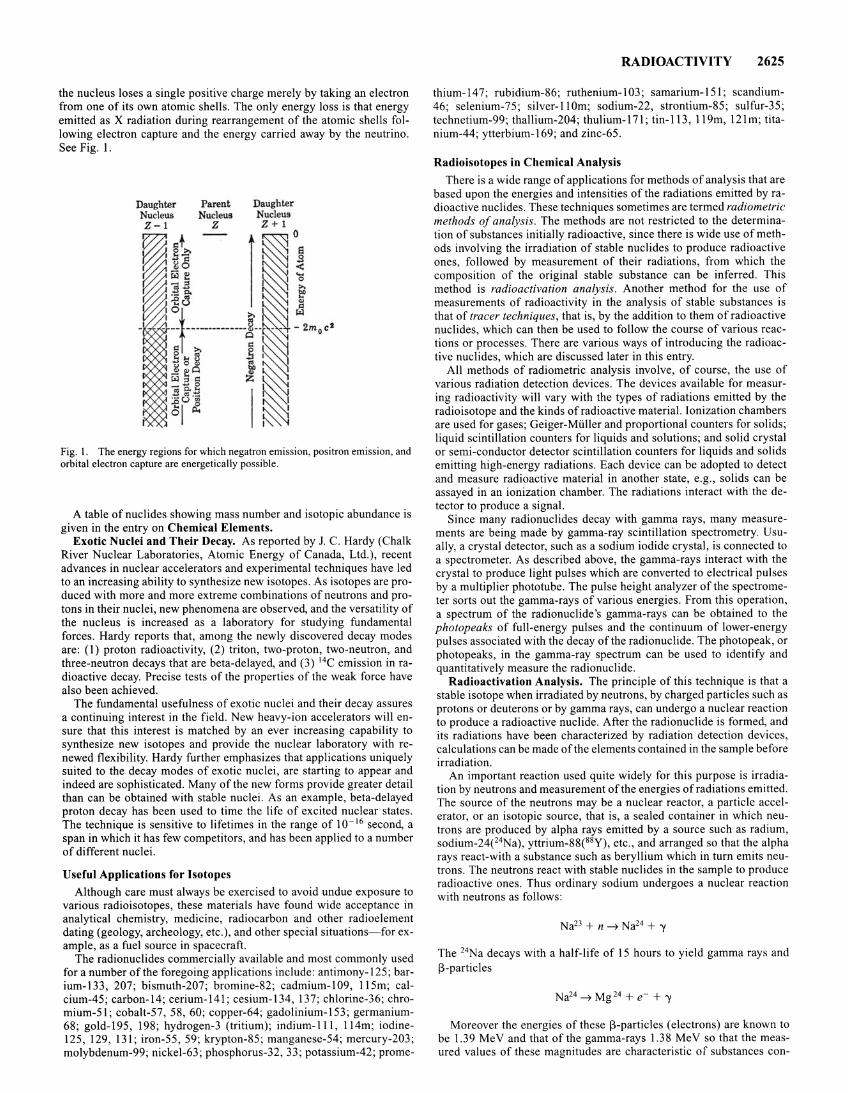
the nucleus loses a single positive charge merely by taking an electron from one of its own atomic shells. The only energy loss is that energy emitted as X radiation during rearrangement of the atomic shells following electron capture and the energy carried away by the neutrino. See Fig. I.
Fig. I. The energy regions for which negatron emission, positron emission, and orbital electron capture are energetically possible.
A table of nuclides showing mass number and isotopic abundance is given in the entry on Chemical Elements.
Exotic Nuclei and Their Decay. As reported by J. C. Hardy (Chalk River Nuclear Laboratories, Atomic Energy of Canada, Ltd.), recent advances in nuclear accelerators and experimental techniques have led to an increasing ability to synthesize new isotopes. As isotopes are produced with more and more extreme combinations of neutrons and protons in their nuclei, new phenomena are observed, and the versatility of the nucleus is increased as a laboratory for studying fundamental forces. Hardy reports that, among the newly discovered decay modes are: (I) proton radioactivity, (2) triton, two-proton, two-neutron, and three-neutron decays that are beta-delayed, and (3) 14C emission in radioactive decay. Precise tests of the properties of the weak force have also been achieved.
The fundamental usefulness of exotic nuclei and their decay assures a continuing interest in the field. New heavy-ion accelerators will ensure that this interest is matched by an ever increasing capability to synthesize new isotopes and provide the nuclear laboratory with renewed flexibility. Hardy further emphasizes that applications uniquely suited to the decay modes of exotic nuclei, are starting to appear and indeed are sophisticated. Many of the new forms provide greater detail than can be obtained with stable nuclei. As an example, beta-delayed proton decay has been used to time the life of excited nuclear states. The technique is sensitive to lifetimes in the range of 10- 16 second, a span in which it has few competitors, and has been applied to a number of different nuclei.
Useful Applications for Isotopes
Although care must always be exercised to avoid undue exposure to various radioisotopes, these materials have found wide acceptance in analytical chemistry, medicine, radiocarbon and other radioelement dating (geology, archeology, etc.), and other special situations- for example, as a fuel source in spacecraft.
The radionuclides commercially available and most commonly used for a number of the foregoing applications include: antimony-125; barium-133, 207; bismuth-207; bromine-82; cadmium-109, 115m; calcium-45; carbon-14; cerium-141 ; cesium-134, 137; chlorine-36; chromium-51; cobalt-57, 58, 60; copper-64; gadolinium-153; germanium-68; gold-195, 198; hydrogen-3 (tritium); indium-Ill , 114m; iodine-125, 129, 131 ; iron-55 , 59; krypton-85; manganese-54; mercury-203; molybdenum-99; nickel-63; phosphorus-32, 33; potassium-42; prome-
RADIOACTIVITY 2625
thium-147; rubidium-86; ruthenium-103; samarium-151; scandium-46; selenium-75; silver-110m; sodium-22, strontium-85; sulfur-35; technetium-99; thallium-204; thulium-171; tin-113, 119m, 121m; titanium-44; ytterbium-169; and zinc-65.
Radioisotopes in Chemical Analysis
There is a wide range of applications for methods of analysis that are based upon the energies and intensities of the radiations emitted by radioactive nuclides. These techniques sometimes are termed radiometric methods of analysis. The methods are not restricted to the determination of substances initially radioactive, since there is wide use of methods involving the irradiation of stable nuclides to produce radioactive ones, followed by measurement of their radiations, from which the composition of the original stable substance can be inferred. This method is radioactivation analysis. Another method for the use of measurements of radioactivity in the analysis of stable substances is that of tracer techniques, that is, by the addition to them of radioactive nuclides, which can then be used to follow the course of various reactions or processes. There are various ways of introducing the radioactive nuclides, which are discussed later in this entry.
All methods of radiometric analysis involve, of course, the use of various radiation detection devices. The devices available for measuring radioactivity will vary with the types of radiations emitted by the radioisotope and the kinds of radioactive material. Ionization chambers are used for gases; Geiger-Muller and proportional counters for solids; liquid scintillation counters for liquids and solutions; and solid crystal or semi-conductor detector scintillation counters for liquids and solids emitting high-energy radiations. Each device can be adopted to detect and measure radioactive material in another state, e.g., solids can be assayed in an ionization chamber. The radiations interact with the detector to produce a signal.
Since many radionuclides decay with gamma rays, many measurements are being made by gamma-ray scintillation spectrometry. Usually, a crystal detector, such as a sodium iodide crystal, is connected to a spectrometer. As described above, the gamma-rays interact with the crystal to produce light pulses which are converted to electrical pulses by a multiplier phototube. The pulse height analyzer of the spectrometer sorts out the gamma-rays of various energies. From this operation, a spectrum of the radionuclide's gamma-rays can be obtained to the photopeaks of full-energy pulses and the continuum of lower-energy pulses associated with the decay of the radionuclide. The photopeak, or photopeaks, in the gamma-ray spectrum can be used to identify and quantitatively measure the radionuclide.
Radioactivation Analysis. The principle of this technique is that a stable isotope when irradiated by neutrons, by charged particles such as protons or deuterons or by gamma rays, can undergo a nuclear reaction to produce a radioactive nuclide. After the radionuclide is formed, and its radiations have been characterized by radiation detection devices, calculations can be made of the elements contained in the sample before irradiation.
An important reaction used quite widely for this purpose is irradiation by neutrons and measurement ofthe energies of radiations emitted. The source of the neutrons may be a nuclear reactor, a particle accelerator, or an isotopic source, that is, a sealed container in which neutrons are produced by alpha rays emitted by a source such as radium, sodium-24e4Na), yttrium-88(88Y), etc., and arranged so that the alpha rays react-with a substance such as beryllium which in turn emits neutrons. The neutrons react with stable nuclides in the sample to produce radioactive ones. Thus ordinary sodium undergoes a nuclear reaction with neutrons as follows:
Na23 + n ~ Na24 + 'Y
The 24Na decays with a half-life of 15 hours to yield gamma rays and [)-particles
Na24 ~ Mg 24 + e- + 'Y
Moreover the energies of these [)-particles (electrons) are known to be 1.39 MeV and that of the gamma-rays 1.38 MeV so that the measured values of these magnitudes are characteristic of substances con-
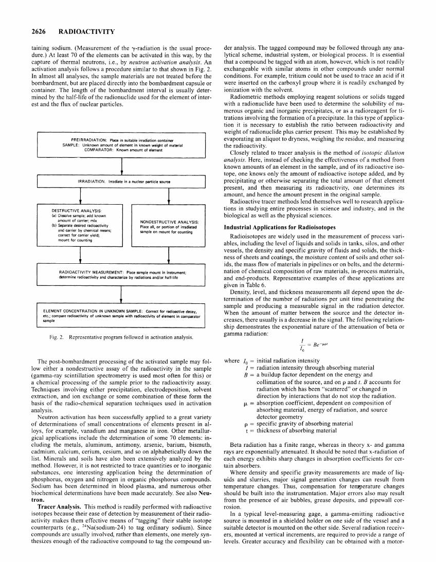
2626 RADIOACTIVITY
tammg sodium. (Measurement of the -y-radiation is the usual procedure.) At least 70 of the elements can be activated in this way, by the capture of thermal neutrons, i.e., by neutron activation analysis. An activation analysis follows a procedure similar to that shown in Fig. 2. In almost all analyses, the sample materials are not treated before the bombardment, but are placed directly into the bombardment capsule or container. The length of the bombardment interval is usually determined by the half-life of the radionuclide used for the element of interest and the flux of nuclear particles.
PRE IRRADIATION: Place in suitable irradiation container SAMPLE: Unknown amount of element in known weight of material
COMPARATOR: Known amount of element
IRRADIATION. Irradiate in a nuclear particle source
! ! DESTRUCTIVE ANALYSIS: (a) Dissolve sample; add known
amount of carrier; mix NONDESTRUCTIVE ANALYSIS: (b) Separate desired radioactivity Place all, or portion of irradiated
and carrier by chemical means; sample on mount for counting correct for carrier yield; mount for counting
! ! RADIOACTIVITY MEASUREMENT: Place sample mount in instrument; determine radioactivity and characterize by radiations and/or half·life
ELEMENT CONCENTRATION IN UNKNOWN SAMPLE: Correct for radioactive decay, etc.; compare radioactivity of unknown sample with radioactivity of element in comparator sample
Fig. 2. Representative program followed in activation analysis.
The post-bombardment processing of the activated sample may follow either a nondestructive assay of the radioactivity in the sample (gamma-ray scintillation spectrometry is used most often for this) or a chemical processing of the sample prior to the radioactivity assay. Techniques involving either precipitation, electrodeposition, solvent extraction, and ion exchange or some combination of these form the basis of the radio-chemical separation techniques used in activation analysis.
Neutron activation has been successfully applied to a great variety of determinations of small concentrations of elements present in alloys, for example, vanadium and manganese in iron. Other metallurgical applications include the determination of some 70 elements: including the metals, aluminum, antimony, arsenic, barium, bismuth, cadmium, calcium, cerium, cesium, and so on alphabetically down the list. Minerals and soils have also been extensively analyzed by the method. However, it is not restricted to trace quantities or to inorganic substances, one interesting application being the determination of phosphorus, oxygen and nitrogen in organic phosphorus compounds. Sodium has been determined in blood plasma, and numerous other biochemical determinations have been made accurately. See also Neutron.
Tracer Analysis. This method is readily performed with radioactive isotopes because their ease of detection by measurement of their radioactivity makes them effective means of "tagging" their stable isotope counterparts (e.g., 24Na(sodium-24) to tag ordinary sodium). Since compounds are usually involved, rather than elements, one merely synthesizes enough of the radioactive compound to tag the compound un-
der analysis. The tagged compound may be followed through any analytical scheme, industrial system, or biological process. It is essential that a compound be tagged with an atom, however, which is not readily exchangeable with similar atoms in other compounds under normal conditions. For example, tritium could not be used to trace an acid if it were inserted on the carboxyl group where it is readily exchanged by ionization with the solvent.
Radiometric methods employing reagent solutions or solids tagged with a radionuclide have been used to determine the solubility of numerous organic and inorganic precipitates, or as a radioreagent for titrations involving the formation of a precipitate. In this type of application it is necessary to establish the ratio between radioactivity and weight ofradionuclide plus carrier present. This may be established by evaporating an aliquot to dryness, weighing the residue, and measuring the radioactivity.
Closely related to tracer analysis is the method of isotopic dilution analysis. Here, instead of checking the effectiveness of a method from known amounts of an element in the sample, and of its radioactive isotope, one knows only the amount of radioactive isotope added, and by precipitating or otherwise separating the total amount of that element present, and then measuring its radioactivity, one determines its amount, and hence the amount present in the original sample.
Radioactive tracer methods lend themselves well to research applications in studying entire processes in science and industry, and in the biological as well as the physical sciences.
Industrial Applications for Radioisotopes
Radioisotopes are widely used in the measurement of process variables, including the level of liquids and solids in tanks, silos, and other vessels, the density and specific gravity of fluids and solids, the thickness of sheets and coatings, the moisture content of soils and other solids, the mass flow of materials in pipelines or on belts, and the determination of chemical composition ofraw materials, in-process materials, and end-products. Representative examples of these applications are given in Table 6.
Density, level, and thickness measurements all depend upon the determination of the number of radiations per unit time penetrating the sample and producing a measurable signal in the radiation detector. When the amount of matter between the source and the detector increases, there usually is a decrease in the signal. The following relationship demonstrates the exponential nature of the attenuation of beta or gamma radiation:
where !0 = initial radiation intensity I = radiation intensity through absorbing material
B = a buildup factor dependent on the energy and collimation of the source, and on p and t. B accounts for radiation which has been "scattered" or changed in direction by interactions that do not stop the radiation.
f.L = absorption coefficient, dependent on composition of absorbing material, energy of radiation, and source detector geometry
p = specific gravity of absorbing material t = thickness of absorbing material
Beta radiation has a finite range, whereas in theory x- and gamma rays are exponentially attenuated. It should be noted that x-radiation of each energy exhibits sharp changes in absorption coefficients for certain absorbers.
Where density and specific gravity measurements are made of liquids and slurries, major signal generation changes can result from temperature changes. Thus, compensation for temperature changes should be built into the instrumentation. Major errors also may result from the presence of air bubbles, grease deposits, and pipewall corrosion.
In a typical level-measuring gage, a gamma-emitting radioactive source is mounted in a shielded holder on one side of the vessel and a suitable detector is mounted on the other side. Several radiation receivers, mounted at vertical increments, are required to provide a range of levels. Greater accuracy and flexibility can be obtained with a motor-
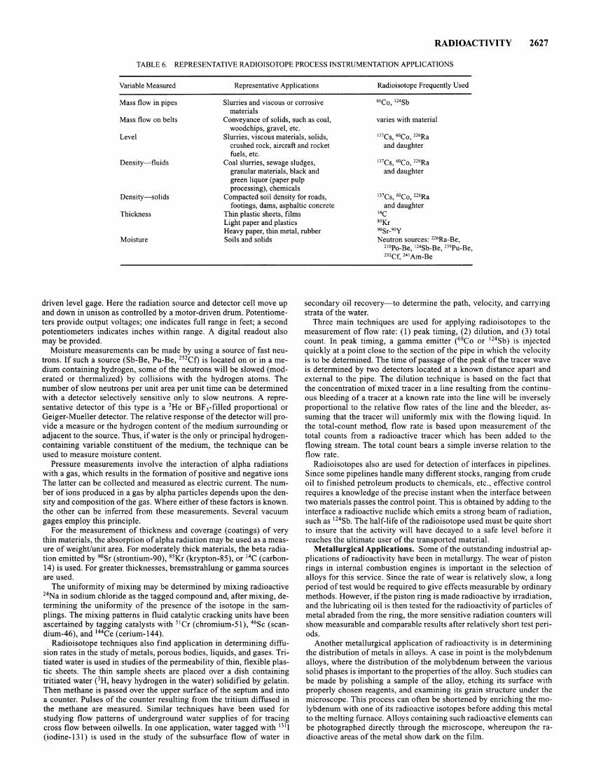
RADIOACTIVITY 2627
TABLE 6. REPRESENTATIVE RADIOISOTOPE PROCESS INSTRUMENTATION APPLICATIONS
Variable Measured Representative Applications Radioisotope Frequently Used
Mass flow in pipes Slurries and viscous or corrosive materials
Mass flow on belts Conveyance of solids, such as coal, woodchips, gravel, etc.
varies with material
Level Slurries, viscous materials, solids, crushed rock, aircraft and rocket fuels, etc.
mcs, 6oco, 226Ra and daughter
Density-fluids Coal slurries, sewage sludges, granular materials, black and green liquor (paper pulp processing), chemicals
mcs, 6oco, 226Ra and daughter
Density-solids Compacted soil density for roads, mcs, 6oco, 226Ra
Thickness footings, dams, asphaltic concrete
Thin plastic sheets, films and daughter
14C
Light paper and plastics s5Kr
Moisture Heavy paper, thin metal, rubber Soils and solids
90Sr-9oy Neutron sources: 226Ra-Be,
210Po-Be, 124Sb-Be, 239Pu-Be, 252Cf, 241 Am-Be
driven level gage. Here the radiation source and detector cell move up and down in unison as controlled by a motor-driven drum. Potentiometers provide output voltages; one indicates full range in feet; a second potentiometers indicates inches within range. A digital readout also may be provided.
Moisture measurements can be made by using a source of fast neutrons. If such a source (Sb-Be, Pu-Be, 252Cf) is located on or in a medium containing hydrogen, some of the neutrons will be slowed (moderated or thermalized) by collisions with the hydrogen atoms. The number of slow neutrons per unit area per unit time can be determined with a detector selectively sensitive only to slow neutrons. A representative detector of this type is a 3He or BFrfilled proportional or Geiger-Mueller detector. The relative response of the detector will provide a measure or the hydrogen content of the medium surrounding or adjacent to the source. Thus, if water is the only or principal hydrogencontaining variable constituent of the medium, the technique can be used to measure moisture content.
Pressure measurements involve the interaction of alpha radiations with a gas, which results in the formation of positive and negative ions The latter can be collected and measured as electric current. The number of ions produced in a gas by alpha particles depends upon the density and composition of the gas. Where either of these factors is known. the other can be inferred from these measurements. Several vacuum gages employ this principle.
For the measurement of thickness and coverage (coatings) of very thin materials, the absorption of alpha radiation may be used as a measure of weight/unit area. For moderately thick materials, the beta radiation emitted by 90Sr (strontium-90), 85Kr (krypton-85), or 14C (carbon-14) is used. For greater thicknesses, bremsstrahlung or gamma sources are used.
The uniformity of mixing may be determined by mixing radioactive 24Na in sodium chloride as the tagged compound and, after mixing, determining the uniformity of the presence of the isotope in the samplings. The mixing patterns in fluid catalytic cracking units have been ascertained by tagging catalysts with 51 Cr (chromium-51), 46Sc (scandium-46), and 144Ce (cerium-144).
Radioisotope techniques also find application in determining diffusion rates in the study of metals, porous bodies, liquids, and gases. Tritiated water is used in studies of the permeability of thin, flexible plastic sheets. The thin sample sheets are placed over a dish containing tritiated water eH, heavy hydrogen in the water) solidified by gelatin. Then methane is passed over the upper surface of the septum and into a counter. Pulses of the counter resulting from the tritium diffused in the methane are measured. Similar techniques have been used for studying flow patterns of underground water supplies of for tracing cross flow between oilwells. In one application, water tagged with 1311 (iodine-131) is used in the study of the subsurface flow of water in
secondary oil recovery-to determine the path, velocity, and carrying strata of the water.
Three main techniques are used for applying radioisotopes to the measurement of flow rate: (1) peak timing, (2) dilution, and (3) total count. In peak timing, a gamma emitter (6°Co or 124Sb) is injected quickly at a point close to the section of the pipe in which the velocity is to be determined. The time of passage of the peak of the tracer wave is determined by two detectors located at a known distance apart and external to the pipe. The dilution technique is based on the fact that the concentration of mixed tracer in a line resulting from the continuous bleeding of a tracer at a known rate into the line will be inversely proportional to the relative flow rates of the line and the bleeder, assuming that the tracer will uniformly mix with the flowing liquid. In the total-count method, flow rate is based upon measurement of the total counts from a radioactive tracer which has been added to the flowing stream. The total count bears a simple inverse relation to the flow rate.
Radioisotopes also are used for detection of interfaces in pipelines. Since some pipelines handle many different stocks, ranging from crude oil to finished petroleum products to chemicals, etc., effective control requires a knowledge of the precise instant when the interface between two materials passes the control point. This is obtained by adding to the interface a radioactive nuclide which emits a strong beam of radiation, such as 124Sb. The half-life of the radioisotope used must be quite short to insure that the activity will have decayed to a safe level before it reaches the ultimate user of the transported material.
Metallurgical Applications. Some of the outstanding industrial applications of radioactivity have been in metallurgy. The wear of piston rings in internal combustion engines is important in the selection of alloys for this service. Since the rate of wear is relatively slow, a long period of test would be required to give effects measurable by ordinary methods. However, if the piston ring is made radioactive by irradiation, and the lubricating oil is then tested for the radioactivity of particles of metal abraded from the ring, the more sensitive radiation counters will show measurable and comparable results after relatively short test periods.
Another metallurgical application of radioactivity is in determining the distribution of metals in alloys. A case in point is the molybdenum alloys, where the distribution of the molybdenum between the various solid phases is important to the properties of the alloy. Such studies can be made by polishing a sample of the alloy, etching its surface with properly chosen reagents, and examining its grain structure under the microscope. This process can often be shortened by enriching the molybdenum with one of its radioactive isotopes before adding this metal to the melting furnace. Alloys containing such radioactive elements can be photographed directly through the microscope, whereupon the radioactive areas of the metal show dark on the film.
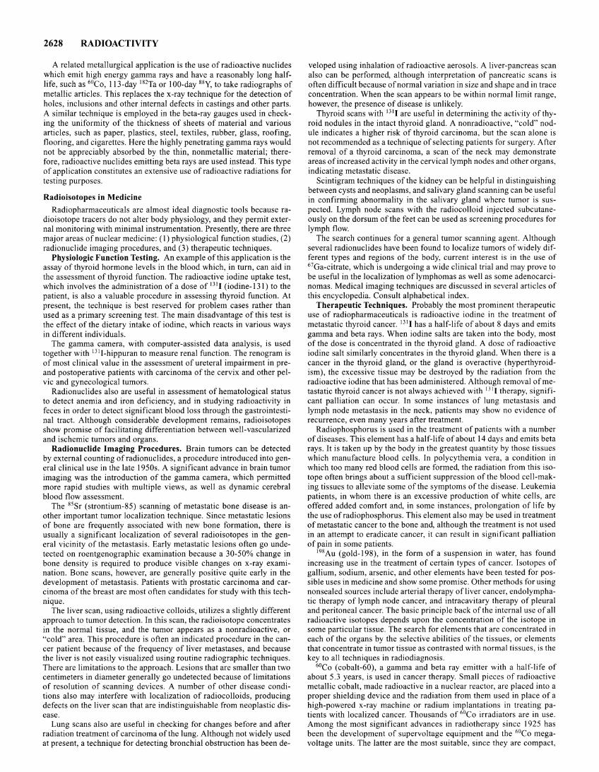
2628 RADIOACTIVITY
A related metallurgical application is the use of radioactive nuclides which emit high energy gamma rays and have a reasonably long halflife, such as 60Co, 113-day 182Ta or 100-day 88Y, to take radiographs of metallic articles. This replaces the x-ray technique for the detection of holes, inclusions and other internal defects in castings and other parts. A similar technique is employed in the beta-ray gauges used in checking the uniformity of the thickness of sheets of material and various articles, such as paper, plastics, steel, textiles, rubber, glass, roofing, flooring, and cigarettes. Here the highly penetrating gamma rays would not be appreciably absorbed by the thin, nonmetallic material; therefore, radioactive nuclides emitting beta rays are used instead. This type of application constitutes an extensive use of radioactive radiations for testing purposes.
Radioisotopes in Medicine
Radiopharmaceuticals are almost ideal diagnostic tools because radioisotope tracers do not alter body physiology, and they permit external monitoring with minimal instrumentation. Presently, there are three major areas of nuclear medicine: (1) physiological function studies, (2) radionuclide imaging procedures, and (3) therapeutic techniques.
Physiologic Function Testing. An example of this application is the assay of thyroid hormone levels in the blood which, in turn, can aid in the assessment of thyroid function. The radioactive iodine uptake test, which involves the administration of a dose of 131 1 (iodine-131) to the patient, is also a valuable procedure in assessing thyroid function. At present, the technique is best reserved for problem cases rather than used as a primary screening test. The main disadvantage of this test is the effect of the dietary intake of iodine, which reacts in various ways in different individuals.
The gamma camera, with computer-assisted data analysis, is used together with 131 1-hippuran to measure renal function. The renogram is of most clinical value in the assessment of ureteral impairment in preand postoperative patients with carcinoma of the cervix and other pelvic and gynecological tumors.
Radionuclides also are useful in assessment of hematological status to detect anemia and iron deficiency, and in studying radioactivity in feces in order to detect significant blood loss through the gastrointestinal tract. Although considerable development remains, radioisotopes show promise of facilitating differentiation between well-vascularized and ischemic tumors and organs.
Radionuclide Imaging Procedures. Brain tumors can be detected by external counting ofradionuclides, a procedure introduced into general clinical use in the late 1950s. A significant advance in brain tumor imaging was the introduction of the gamma camera, which permitted more rapid studies with multiple views, as well as dynamic cerebral blood flow assessment.
The 85 Sr (strontium-85) scanning of metastatic bone disease is another important tumor localization technique. Since metastatic lesions of bone are frequently associated with new bone formation, there is usually a significant localization of several radioisotopes in the general vicinity of the metastasis. Early metastatic lesions often go undetected on roentgenographic examination because a 30-50% change in bone density is required to produce visible changes on x-ray examination. Bone scans, however, are generally positive quite early in the development of metastasis. Patients with prostatic carcinoma and carcinoma of the breast are most often candidates for study with this technique.
The liver scan, using radioactive colloids, utilizes a slightly different approach to tumor detection. In this scan, the radioisotope concentrates in the normal tissue, and the tumor appears as a nonradioactive, or "cold" area. This procedure is often an indicated procedure in the cancer patient because of the frequency of liver metastases, and because the liver is not easily visualized using routine radiographic techniques. There are limitations to the approach. Lesions that are smaller than two centimeters in diameter generally go undetected because of limitations of resolution of scanning devices. A number of other disease conditions also may interfere with localization of radiocolloids, producing defects on the liver scan that are indistinguishable from neoplastic disease.
Lung scans also are useful in checking for changes before and after radiation treatment of carcinoma of the lung. Although not widely used at present, a technique for detecting bronchial obstruction has been de-
vel oped using inhalation of radioactive aerosols. A liver-pancreas scan also can be performed, although interpretation of pancreatic scans is often difficult because of normal variation in size and shape and in trace concentration. When the scan appears to be within normal limit range, however, the presence of disease is unlikely.
Thyroid scans with 1311 are useful in determining the activity of thyroid nodules in the intact thyroid gland. A nonradioactive, "cold" nodule indicates a higher risk of thyroid carcinoma, but the scan alone is not recommended as a technique of selecting patients for surgery. After removal of a thyroid carcinoma, a scan of the neck may demonstrate areas of increased activity in the cervical lymph nodes and other organs, indicating metastatic disease.
Scintigram techniques of the kidney can be helpful in distinguishing between cysts and neoplasms, and salivary gland scanning can be useful in confirming abnormality in the salivary gland where tumor is suspected. Lymph node scans with the radiocolloid injected subcutaneously on the dorsum of the feet can be used as screening procedures for lymph flow.
The search continues for a general tumor scanning agent. Although several radionuclides have been found to localize tumors of widely different types and regions of the body, current interest is in the use of 67Ga-citrate, which is undergoing a wide clinical trial and may prove to be useful in the localization of lymphomas as well as some adenocarcinomas. Medical imaging techniques are discussed in several articles of this encyclopedia. Consult alphabetical index.
Therapeutic Techniques. Probably the most prominent therapeutic use of radiopharmaceuticals is radioactive iodine in the treatment of metastatic thyroid cancer. 1311 has a half-life of about 8 days and emits gamma and beta rays. When iodine salts are taken into the body, most of the dose is concentrated in the thyroid gland. A dose of radioactive iodine salt similarly concentrates in the thyroid gland. When there is a cancer in the thyroid gland, or the gland is overactive (hyperthyroidism), the excessive tissue may be destroyed by the radiation from the radioactive iodine that has been administered. Although removal of metastatic thyroid cancer is not always achieved with 131 1 therapy, significant palliation can occur. In some instances of lung metastasis and lymph node metastasis in the neck, patients may show no evidence of recurrence, even many years after treatment.
Radiophosphorus is used in the treatment of patients with a number of diseases. This element has a half-life of about 14 days and emits beta rays. It is taken up by the body in the greatest quantity by those tissues which manufacture blood cells. In polycythemia vera, a condition in which too many red blood cells are formed, the radiation from this isotope often brings about a sufficient suppression of the blood cell-making tissues to alleviate some of the symptoms of the disease. Leukemia patients, in whom there is an excessive production of white cells, are offered added comfort and, in some instances, prolongation of life by the use of radiophosphorus. This element also may be used in treatment of metastatic cancer to the bone and, although the treatment is not used in an attempt to eradicate cancer, it can result in significant palliation of pain in some patients.
198 Au (gold-198), in the form of a suspension in water, has found increasing use in the treatment of certain types of cancer. Isotopes of gallium, sodium, arsenic, and other elements have been tested for possible uses in medicine and show some promise. Other methods for using nonsealed sources include arterial therapy of liver cancer, endolymphatic therapy of lymph node cancer, and intracavitary therapy of pleural and peritoneal cancer. The basic principle back of the internal use of all radioactive isotopes depends upon the concentration of the isotope in some particular tissue. The search for elements that are concentrated in each of the organs by the selective abilities of the tissues, or elements that concentrate in tumor tissue as contrasted with normal tissues, is the key to all techniques in radiodiagnosis.
6°Co (cobalt-60), a gamma and beta ray emitter with a half-life of about 5.3 years, is used in cancer therapy. Small pieces of radioactive metallic cobalt, made radioactive in a nuclear reactor, are placed into a proper shielding device and the radiation from them used in place of a high-powered x-ray machine or radium implantations in treating patients with localized cancer. Thousands of 6°Co irradiators are in use. Among the most significant advances in radiotherapy since 1925 has been the development of supervoltage equipment and the 6°Co megavoltage units. The latter are the most suitable, since they are compact,
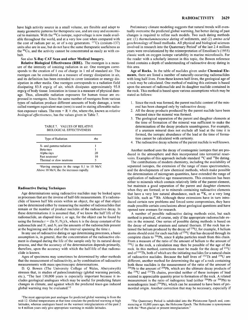
have high activity source in a small volume, are flexible and adapt to many geometric patterns for therapeutic use, and are easy and economical to maintain. With the 6°Co isotope, supervoltage is now made available throughout the world, and at a very low cost when compared with the cost of radium per se, or of x-ray generators. 137Cs (cesium-137) units also are in use, but do not have the same therapeutic usefulness as the 6°Co, and the activity cannot be concentrated as easily as with cobalt.
See also X-Ray CAT Scan and other Medical Imagery. Relative Biological Effectiveness (RBE). The roentgen is a meas
ure of the intensity of ionizing radiation in air. One roentgen corresponds to the creation of 1 esu of charge in 1 ml of standard air. The roentgen can be considered as a measure of energy dissipation in air, and its definition has been extended to cover ionization or energy dissipation in other media. One roentgen corresponds to a radiation field dissipating 83.8 ergs/g of air, which dissipates approximately 93.8 ergs/g of body tissue. Ionization in tissue is a measure of physical damage. Thus, allowable radiation exposures for human tissue are expressed in roentgens. Since the same number of roentgens from various types of radiation produce different amounts of body damage, a term called roentgen equivalent man (rem) is used in stating allowable radiation exposure values. The rem = R X rbe, where rbe, known as relative biological effectiveness, has the values given in Table 7.
TABLE 7. VALUES OF RELATIVE BIOLOGICAL EFFECTIVENESS
Type of Radiation
X- and gamma radiation Beta rays Alpha rays Fast neutrons' Thermal or slow neutrons
rbe
I I 20 10 5
'Having energies in the range 0.1 to 10 MeV Above 10 MeV, the rbe increases rapidly.
Radioactive Dating Techniques
Age determinations using radioactive nuclides may be looked upon as processes that are the inverse of half-life measurements. If a radionuclide of known half life exists within an object, the age of that object can be determined either by measuring the number ofradionuclides that remain or the number of product nuclides of the radioactive decay. In these determinations it is assumed that, if we know the half life of the radionuclide, an elapsed time t, or age, for the object can be found by using the formula t = (In N/N2)/'A, where 'A is the decay constant of the radionuclide and N1 and N2 are the amounts of the radionuclide present at the beginning and the end of the interval spanning the time t.
In any use of radioactive dating or age determining processes, a basic assumption is, in general, that the concentration of the radioactive element is changed during the life of the sample only by its natural decay process, and that the accuracy of the determination depends primarily, therefore, upon the accuracy with which the half-life of that radionuclide is known.
Ages of specimens may sometimes be determined by other methods that the measurement of radioactivity, as by combination of radioactive measurements with mass spectroscopic determinations.
D. Q. Bowen (The University College of Wales, Aberystwyth) stresses that, in studies of paleoclimatology (global warming periods, etc.), "The last 130,000 years is especially important because it includes geological analogues which may be useful for predicting future changes in climate, and against which the predicted trace-gas induced global warming may be evaluated."2
'The most appropriate past analogue for predicted global warming is from the mid-12. Global temperatures at that time simulate the predicted warming at high latitudes, whereas analogues based on the warmest interglaciations of the past 2 to 4 million years only give appropriate warming in middle latitudes.
RADIOACTIVITY 2629
Preliminary climate modeling suggests that natural trends will eventually overcome the predicted global warming, but better dating of past changes is required to refine such models. Two such dating methods are: (I) thermoluminescence dating of sediments, and (2) amino acid geochronology of fossil mollusks. All physical and biological sciences involved in research into the Quaternary Period3 of the last 2.4 million years were revolutionized by the reinterpretation of Emoiliani 's ( 1955) classic work on oxygen isotope variability in marine microfossils. For the reader with a scholarly interest in this topic, the Bowen reference listed contains a depth of understanding of radioactive decay dating in this area.
Age of Rocks. In the table of nuclides given under Chemical Elements, there are listed a number of naturally-occurring radionuclides with long half-lives. From these known half-lives, the geological age of a rock may be calculated. One method of making this estimate is based upon the amount of radionuclide and its daughter nuclide contained in the rock. This method is based upon various assumptions which may be stated as follows:
1. Since the rock was formed, the parent nuclidic content ofthe mineral has been changed only by radioactive decay.
2. All the decay products produced by the parent nuclide have been retained since the mineral was formed.
3. The geological separation of the parent and daughter elements at the time of formation of the mineral was sufficient to make the determination of the decay products unambiguous. For example, if a uranium mineral does not exclude all lead at the time it is formed, the isotopic abundance of the lead at the time of formation cannot be calculated with certainty.
4. The radioactive decay scheme of the parent nuclide is well known.
Another method uses the decay of cosmogenic isotopes that are produced in the atmosphere and then incorporated into terrestrial reservoirs. Examples of this approach include standard 14C and 10Be dating.
The contributions of modern chemistry, including the availability of separated isotopes, the extension of the range of mass spectrometers, and the developments of new chemical methods, which make possible the determination of microgram quantities, have extended the range of application of radioactive age measurements. This extension has been either to minerals which contain relatively little of the parent element, but maintain a good separation of the parent and daughter elements when they are formed; or to minerals containing radioactive elements that have a very low natural abundance, such as 4°K, or a very long half-life, such as 87Rb. Although these extensions have in turn introduced certain new problems and forced some compromises, they have made possible certain conclusions about geological questions and have opened new avenues for research.
A number of possible radioactive dating methods exist, but each method is practical, of course, only if the appropriate radionuclide exists in the mineral. One series of possible dating methods is based on the decay of natural uranium and natural thorium. If the rock has retained the helium produced by the decay of 238U, for example, 8 helium atoms should exist for each nuclide of 238U that has decayed through its complete chain to 206Pb, since 8 alpha particles result from this chain. From a measure of the ratio of the amount of helium to the amount of 238U in the rock, a calculation may then be possible of the age of the rock. In this method, corrections must be made for the decay of 235U and of 232Th, both of which are the initiating nuclides for a natural chain of radioactive nuclides. Because the half lives of 232Th and 238U are different, another method for determining the age of a rock containing both these nuclides is the measurement of the ratio of the amount of 206Pb to the amount of 208Pb, which are the ultimate decay products of the 238U and 232Th chains, provided neither of these isotopes of lead existed in appreciable quantity prior to formation of the rock. A related measurement is the ratio of radiogenic lead (either 206Pb or 208Pb) to nonradiogenic lead e04Pb ), which can be assumed to have been of primordial origin. Another correction that may be necessary, especially if
3The Quaternary Period is subdivided into the Pleistocene Epoch and, commencing at 10,000 years ago, the Holocene Epoch. The Holocene is synonymous with the "Post-glacial or present interglaciation."
2630 RADIOACTIVITY
the rock comes from a high altitude, is a determination of the amount of helium that has been produced as a result of spallation reactions caused by very high-energy cosmic radiation. Other radioactive agedating systems are those of potassium-argon (which consists of the decay of 4°K to 40 Ar, by electron capture, a process with a half-life of 1.27 X 10¹⁰ years) and rubidium-strontium which consists of the decay of R7Rb to 87 Sr, by electron emission, a process having a half-life of 4.7 X l 0 10 years.
One conclusion drawn from radioactive measurements is that the pre-Cambrian history of the earth's crust extends beyond 2, 700 million years. The pegmatites that have been found to be this old are located in North America and Australia, and they probably exist on all the continents. The oldest rocks in the United States that have been measured are on the south rim of the Bridger Mountains near the Wind River Canyon in Wyoming. These ancient pegmatites intrude geologic formations of sedimentary and volcanic rocks that themselves are the result of even more ancient processes than those in which they were formed. Thus, a period of the order of 3,000 million years or more is available for geologic processes that have formed the crust seen today.
Next, the facility to measure the absolute age of micas in igneous intrusives of pre-Cambrian sediments provides a method of correlating these sediments wherever they occur in much the same fashion that fossil correlation of more recent sedimentary formations is possible. A method that is independent of the lithologic characteristics and the general structure of the sediments will provide a crucial test of the validity of these criteria, which have been all that was available to the geologist. Further, any attempts to look for more subtle evidence of such things as changes in the composition of the atmosphere or origins of life itself must be fitted into a time scale of the pre-Cambrian.
Radiocarbon Dating. This is a method of estimating the age of carbon-containing materials by measuring the radioactivity of the carbon in them. The validity of this method rests upon certain observations and assumptions, of which the following statement is a brief summary. The cosmic rays entering the atmosphere undergo various transformations, one of which results in the formation of neutrons, which in turn, induce nuclear reactions in the nuclei of individual atoms of the atmosphere. The dominant reaction is
in which the neutrons react with the nuclei of nitrogen atoms of mass number 14 (which make up the nitrogen molecules that constitute nearly ~ of the atmosphere) to form carbon atoms of mass number 14 and protons (p). The 14C atoms are radioactive, having a half life of about 5730 years. The largest rate of formation of 14C atoms from cosmic rays is at 30,000-50,000 feet (9,144-15,240 meters) above sea level and at higher geomagnetic latitudes, although formation occurs at varying rates throughout the entire atmosphere. The 14C atoms react with oxygen in the atmosphere to form carbon dioxide, which is mixed with the nonradioactive carbon dioxide in the atmosphere, and with it gains worldwide distribution by various processes. The radioactive 14C02 enters the carbon cycle in which plants take up carbon dioxide from the atmosphere to form carbohydrates, which enter through plant foods into the composition of animals. In another world-wide process, also of exchange nature, carbon dioxide is dissolved in seawater and then, under changing conditions of acidity and temperature, is partially evolved from the seawater again. As a result of these and other processes, the 14C formed in the atmosphere by cosmic rays tends to become distributed throughout all the nonradioactive carbon, not only in the atmosphere, but in the biosphere, the hydrosphere, and even the upper levels of the lithosphere (there are many carbonate-containing minerals).
Obviously this wide distribution of the 14C formed in the atmosphere takes time; it is believed to require a period of 500-1000 years. This time is not, however, a deterrent to radiocarbon dating because of two factors; the long half-life of 14C and the relatively constant rate of cosmic-ray formation of 14C in the earth's atmosphere over the most recent several thousands of years. These considerations lead to the conclusion that the proportion of 14C in the carbon reservoir of the
earth is constant, the addition by cosmic ray production being in balance with the loss by radioactive decay. If this conclusion is warranted, then the carbon dioxide on earth many centuries ago had the same content of radioactive carbon as the carbon dioxide on earth today. Thus, radioactive carbon in the wood of a tree growing centuries ago had the same content as that in carbon on earth today. Therefore, if we wish to determine how long ago a tree was cut down to build an ancient fire, all we need to do is to determine the relative 14C content of the carbon in the charcoal remaining, using the value we have determined for the half life of 14C. If the carbon from the charcoal in an ancient cave has only ~ as much 14C radioactivity as does carbon on earth today, then we can conclude that the tree which furnished the firewood grew 5730 ± 30 years ago. See also discussion on the age determination of the bristlecone pines in the White Mountains of California in the entry on Pine Trees.
As pointed out by Muller (1977), there are well documented differences between the ages of materials determined by dating with radioisotopes and the ages determined by other means, such as tree-ring counting. In addition to systematic effects, there are statistical errors due to the limited number of atoms observed. Both types of errors can be considered to be fluctuations inn, the number of atoms observed. A relationship can be derived between the magnitude of these fluctuations and the resulting error in the estimation of age of the sample:
n= ke-Y, or t = T ln(k/n)
where T is the mean life of the isotope, t is the age of the sample, and k is the initial number of radioactive atoms in the sample multiplied by the efficiency for detecting them. If n has errors associated with it of +on 1 and -on2, then the corresponding values oft will be:
_ k _ +lin (I - on2 In ·~ f - T In ~ - T In (kIn) - In (I + on In
n&n2 I '
Muller has shown that for n = I, inverse Poisson statistics gives n 1
1.36 and n2 = 0.62 and thus the foregoing equation becomes:
t =TIn (k)~~~~~
Further details of this method can be found in aforementioned reference.
Determination of the ratio of two oxygen isotopes has been effective in fixing the age of fossil sediments and can provide information about ice formation and, possibly, water temperatures. The lighter isotope 160 evaporates preferentially and thus precipitation and hence ice in glaciers and polar caps should be enriched with 160 relative to seawater. Thus, fluctuations in the amount of water locked up as ice can be determined from variations in the oxygen isotope ratio of fossils which have been locked up in deep-sea sediments. And, because this ratio also varies with water temperature, thermal information also can be gleaned. Kennett (University of Rhode Island) has employed this technique in determining when significant amounts of ice first formed at the poles. This research has indicated that the Antarctic ice cap formed only about 16 million years ago, after Australia had split off and moved away from Antarctica, leaving the latter continent isolated at the pole and surrounded by the fast-moving circumpolar current. More details are given by Hammond (1976).
In 1986, J. I. Hedges and colleagues (see reference) reported on how dissolved and particulate organic material transported by rivers can provide a continuous record of physical and biological processes at work within the drainage basin. Rivers also contribute a potentially important quantity of organic matter to the ocean, where the dissolved component may exhibit an appreciable residence time. Although the magnitude of the global river contribution is known, the dynamics of organic materials within terrestrial ecosystems and their effects on the composition of the corresponding marine reservoirs are poorly understood. This is particularly true for rivers draining topical rain forests, which account for about 40% of the total riverine organic carbon discharged into the ocean. Hedges and a team studied the Amazon River System using organic carbon-14 dating methods. They found that coarse and fine suspended particulate organic materials and dissolved humic and fulvic acids transported by the Amazon River all contain bomb-produced
carbon-14, indicating relatively rapid turnover of the parent carbon pools. However, the carbon-14 contents of these coexisting carbon forms are measurably different and may reflect varying degrees of retention of soils in the drainage basin.
Dating by Accelerator Mass Spectrometry. The cyclotron is mainly used as a source of energetic particles. The cyclotron also can be used as a very sensitive mass spectrometer. Alvarez and Cornog ( 1939) were the first researchers to use a cyclotron in this manner. This was in connection with their discovery of the true nuclear properties of 3He and tritium. Within the last few years, Muller and associates at the Lawrence Berkeley Laboratory have used this method in a search for integrally charged quarks in terrestrial material. For radioisotope dating, the cyclotron is tuned to accelerate the isotope of interest and the sample is introduced into the ion source, preferably as a gas. For radioisotope dating, the greatest gains over radioactive counting techniques apply to the longer-lived species, which have lower decay rates. It has been estimated that the cyclotron can be used to detect atoms or simple molecules that are present at the 10- 16 level or greater. For 14C dating, the Berkeley investigators indicate that one should be able to go back 40,000 to 100,000 years with 1-to-1 00 microgram carbon samples; for 10Be dating, 10-30 million years with from 1 cubic millimeter to 10 cubic centimeter rock samples; and for tritium dating, 160 years with a !-liter water sample. Over 50 cyclotrons are in operation today that could perform radioisotope dating and, although the instruments are costly, the cost for a dating determination experiment may not be much higher than for decay dating technology.
Other isotopes with which an accelerator mass spectrometer may be effective include 26 AI, 36Cl, 53Mn, 81 K, and 1291. Chlorine-36 has a halflife of 300,000 years and may be used for dating water in underground reservoirs. 10Be is produced in the atmosphere at the rate of 1.5 X 1 o-2
atom cm- 2 sec- 1 by cosmic rays that break up oxygen and nitrogen nuclei. 10Be has been used in studies of both seafloor spreading and manganese nodule formation. Although tritium eH) has a short mean life of 17.8 years, tritium dating has been important in cosmic-ray physics, hydrology, meteorology, and oceanography. For example, if one desires to know how long an underground water reservoir may require for refilling, the age of the water can be determined by tritium dating methods.
In 1986, researchers at the Research Laboratory for Archaeology and the History of Art, University of Oxford, reported on how the radioactive carbon-14 isotope can be separated from other atoms in a sample by use of accelerator mass spectrometry, thus making it possible to derive more accurate chronologies from much smaller archaeological or anthropological specimens. For details, consult Hedges/Gowlett reference listed.
In 1992, K. R. Ludwig and colleagues of the U.S. Geological Survey reported on their use of mass-spectrometric 230Th-234U-238U dating of the Devil's Hole calcite vein (Derbyshire, England), which contains a long-term climatic record, but requires accurate chronologie control for its interpretation. Mass-spectrometric U-series ages for samples from core DH = 11 yielded 230Th ages, with precisions ranging from less than 1000 years to less than 50,000 years for the oldest samples. The 234U/238U ages could be determined to a precision of approximately 20,000 years for all ages. Tentatively, the researchers have concluded, "Overall, the U-series ages form a remarkably self-consistent suite of age determinations. Because this consistency is both internal (from replicate samples) and external (from the stability of the overall age-distance trend), it seems highly unlikely that the dates have been significantly corrupted by open-system processes, such as uranium gain or loss or alpha-recoil phenomena. The apparent ideality of the U-Th system in the vein material is probably the result of continuous submergence in water that showed limited secular variations of its physical and chemical properties."
Non-Radioactivity Dating Techniques
Several methods in addition to those involving radioactivity have been used to estimate the ages of various materials and objects.
Obsidian Hydration Rate. Obsidian (rhyolitic volcanic glass) can be used as a key to age determinations for both archeological and geological purposes. As pointed out by Friedman and Long (1976), the method depends upon the fact that obsidian absorbs water from the at-
RADIOACTIVITY 2631
mosphere to form a hydrated layer, which thickens with time as the water slowly diffuses into the glass. The hydrated layer can be observed and measured under a microscope on thin sections cut normal to the surface. To convert the measured hydration thickness to an age, the equation relating thickness to time must be known. This requires not only the form of the equation (functional dependence), but also the constants in it. Prior to the early 1960s, age could be related to hydration thickness only if combined with known history of a region or through the use of carbon-14 techniques. In the mid-1960s, Friedman and associates conducted actual experimental hydration experiments on obsidian, exposing the materials (taken from the Valles Mountains in New Mexico) to a temperature of 1 00°C and steam at a pressure of I atmosphere over a 4-year period. An equation of the form, T = kt112 was developed, where T = thickness of hydration layer, t = time, and k is a constant. Investigators have developed a procedure for calculating hydration rate of a sample from its silica content, refractive index, or chemical index and a knowledge of the effective temperature at which the hydration occurred. The effective hydration temperature (EHT) can either be measured or approximated from weather records. The investigators concluded that if the EHT can be determined and measured for the hydration of a particular obsidian, it should be possible to carry out absolute dating to ± 10% of the true age over periods as short as several years and as long as millions of years.
Manufactured Glass Objects. Other investigators (Lanford, 1977) have extended the principles applying to obsidian to manufactured glass, which extends back for thousands of years and thus can be useful to archeologists. However, as observed by Lanford, one cannot use the same optical method for measuring the thickness of hydration layers as used with obsidian. The hydration of the two materials differs. Also, glass that is less than a few hundred years old would generally have hydration layers thinner than the wavelength of visible light. The optical method is destructive in that it requires removal of a slice of glass from an object, something much discouraged by art historians and dealers. The Lanford method involves a resonant nuclear reaction between 15N and 1H for measuring the distribution of hydrogen in solids. With this technique, complete depth profiles of the surface hydration layer can be obtained in a fully nondestructive manner. Lanford summarizes by observing that this method of hydration dating need not be limited to glass. Since most silicates are unstable against slow reactions with atmospheric water, many may develop surface hydration layers suitable for dating and authenticating. The glazes on pottery are chemically similar to glass, and it may be possible that a dating method for glazed pottery based upon these procedures can be developed.
Amino Acid Racemization. This dating method is based upon the incorporation of L-amino acids exclusively into proteins by living organisms. As pointed out by the researchers Masters and Zimmerman (1978), given sufficient periods of time over which proteins are preserved after synthesis, a number of spontaneous chemical reactions take place. Among these is racemization, which converts L-amino acids into their enantiomers, the o-amino acids. The different amino acids racemize at various rates, and these rates (as with all chemical reactions) are proportional to temperature. One of the fastest racemization rates known is that of aspartic acid, with a half-life of 15,000 years at 20°C. It follows, then, that the older a fossilized material may be, the higher will be its o-aspartic acid content or o/L Asp ratio. Once the kasp
is known for a given fossil locality, the age of a specimen can be calculated from the o/L ratio.
This method was used in the examination of an Eskimo who died 1600 years ago. The body was discovered in a frozen state on St. Lawrence Island, Alaska in 1972 and remained frozen until it was brought to Fairbanks in 1973. Examination of the female individual revealed that she had a skull fracture, probably resulting from instant burial caused by a landslide. Aspartic acid racemization analysis of a tooth from the mummy yielded an age at death of 53 ± 5 years, which correlated well with earlier estimates based upon morphological features. This method is an example of the need to preserve mummies (Alaskan, Egyptian, and Peruvian, among others) for application of new dating techniques as they develop.
The racemization dating technique fell out of favor with many paleoanthropologists in the 1980s, but is staging a comeback of accep-
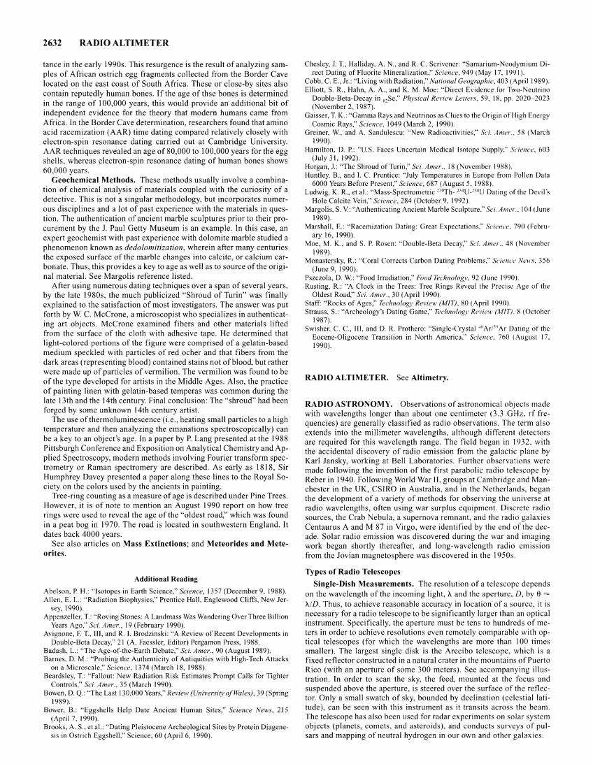
2632 RADIO ALTIMETER
tance in the early 1990s. This resurgence is the result of analyzing samples of African ostrich egg fragments collected from the Border Cave located on the east coast of South Africa. These or close-by sites also contain reputedly human bones. If the age of thse bones is determined in the range of 100,000 years, this would provide an additional bit of independent evidence for the theory that modern humans came from Africa. In the Border Cave determination, researchers found that amino acid racemization (AAR) time dating compared relatively closely with electron-spin resonance dating carried out at Cambridge University. AAR techniques revealed an age of 80,000 to 100,000 years for the egg shells, whereas electron-spin resonance dating of human bones shows 60,000 years.
Geochemical Methods. These methods usually involve a combination of chemical analysis of materials coupled with the curiosity of a detective. This is not a singular methodology, but incorporates numerous disciplines and a lot of past experience with the materials in question. The authentication of ancient marble sculptures prior to their procurement by the J. Paul Getty Museum is an example. In this case, an expert geochemist with past experience with dolomite marble studied a phenomenon known as dedolomitization, wherein after many centuries the exposed surface of the marble changes into calcite, or calcium carbonate. Thus, this provides a key to age as well as to source of the original material. See Margolis reference listed.
After using numerous dating techniques over a span of several years, by the late 1980s, the much publicized "Shroud of Turin" was finally explained to the satisfaction of most investigators. The answer was put forth by W. C. McCrone, a microscopist who specializes in authenticating art objects. McCrone examined fibers and other materials lifted from the surface of the cloth with adhesive tape. He determined that light-colored portions of the figure were comprised of a gelatin-based medium speckled with particles of red ocher and that fibers from the dark areas (representing blood) contained stains not of blood, but rather were made up of particles of vermilion. The vermilion was found to be of the type developed for artists in the Middle Ages. Also, the practice of painting linen with gelatin-based temperas was common during the late 13th and the 14th century. Final conclusion: The "shroud" had been forged by some unknown 14th century artist.
The use of thermoluminescence (i.e., heating small particles to a high temperature and then analyzing the emanations spectroscopically) can be a key to an object's age. In a paper by P. Lang presented at the 1988 Pittsburgh Conference and Exposition on Analytical Chemistry and Applied Spectroscopy, modern methods involving Fourier transform spectrometry or Raman spectromery are described. As early as 1818, Sir Humphrey Davey presented a paper along these lines to the Royal Society on the colors used by the ancients in painting.
Tree-ring counting as a measure of age is described under Pine Trees. However, it is of note to mention an August 1990 report on how tree rings were used to reveal the age of the "oldest road," which was found in a peat bog in 1970. The road is located in southwestern England. It dates back 4000 years.
See also articles on Mass Extinctions; and Meteorides and Meteorites.
Additional Reading
Abelson, P. H.: "Isotopes in Earth Science," Science, 1357 (December 9, 1988). Allen, E. L.: "Radiation Biophysics," Prentice Hall, Englewood Cliffs, New Jer
sey, 1990). Appenzeller, T.: "Roving Stones: A Landmass Was Wandering Over Three Billion
Years Ago," Sci. A mer., 19 (February 1990). Avignone, F. T., Ill, and R.I. Brodzinski: "A Review of Recent Developments in
Double-Beta Decay," 21 (A. Faessler, Editor) Pergamon Press, 1988. Badash, L.: "The Age-of-the-Earth Debate," Sci. Amer., 90 (August 1989). Barnes, D. M.: "Probing the Authenticity of Antiquities with High-Tech Attacks
on a Microscale," Science, 1374 (March 18, 1988). Beardsley, T.: "Fallout: New Radiation Risk Estimates Prompt Calls for Tighter
Controls," Sci. A mer., 35 (March 1990). Bowen, D. Q.: "The Last 130,000 Years," Review (University of Wales), 39 (Spring
1989). Bower, B.: "Eggshells Help Date Ancient Human Sites," Science News, 215
(April 7, 1990). Brooks, A. S., et al.: "Dating Pleistocene Archeological Sites by Protein Diagene
sis in Ostrich Eggshell," Science, 60 (April6, 1990).
Chesley. J. T., Halliday, A. N., and R. C. Scrivener: "Samarium-Neodymium Direct Dating of Fluorite Mineralization," Science, 949 (May 17, 1991 ).
Cobb, C. E., Jr.: "Living with Radiation," National Geographic, 403 (April 1989). Elliott, S. R., Hahn, A. A., and K. M. Moe: "Direct Evidence for Two-Neutrino
Double-Beta-Decay in 82Se," Phvsical Review Letters, 59. I R, pp. 2020-2023 (November 2, 1987).
Gaisser, T. K.: "Gamma Rays and Neutrinos as Clues to the Origin of High Energy Cosmic Rays," Science, 1049 (March 2, 1990).
Greiner, W., and A. Sandulescu: "New Radioactivities," Sci. Amer., 5X (March 1990).
Hamilton, D. P.: "U.S. Faces Uncertain Medical Isotope Supply," Science, 603 (July 31, 1992).
Horgan, J.: "The Shroud of Turin," Sci. Amer., 18 (November 1988). Huntley. B., and I. C. Prentice: "July Temperatures in Europe from Pollen Data
6000 Years Before Present," Science, 687 (August 5, 1988). Ludwig, K. R., et al.: "Mass-Spectrometric ""Th- 214 U-'"U Dating of the Devil's
Hole Calcite Vein," Science, 284 (October 9, 1992). Margolis, S. V: "Authenticating Ancient Marble Sculpture," Sci. A mer .. 104 (June
1989). Marshall, E.: "Racemization Dating: Great Expectations," Science, 790 ( Febru
ary 16, 1990). Moe, M. K., and S. P. Rosen: "Double-Beta Decay," Sci. Amer., 48 (November
1989). Monastersky, R.: "Coral Corrects Carbon Dating Problems," Scienc<' News. 356
(June 9, 1990). Pszczo1a, D. W.: "Food Irradiation," Food Technology, 92 (June 1990). Rusting, R.: "A Clock in the Trees: Tree Rings Reveal the Precise Age of the
Oldest Road," Sci. Amer., 30 (April 1990). Staff: "Rocks of Ages," Technology Review (MIT). 80 (April 1990). Strauss, S.: "Archeology's Dating Game," Technology Review (MIT). 8 (October
1987). Swisher. C. C., Ill, and D. R. Prothero: "Single-Crystal 411Arfl9 Ar Dating of the
Eocene-Oligocene Transition in North America," Science. 760 (August 17, 1990).
RADIO ALTIMETER. See Altimetry.
RADIO ASTRONOMY. Observations of astronomical obJects made with wavelengths longer than about one centimeter (3.3 GHz, rf frequencies) are generally classified as radio observations. The term also extends into the millimeter wavelengths, although different detectors are required for this wavelength range. The field began in 1932, with the accidental discovery of radio emission from the galactic plane by Karl Jansky, working at Bell Laboratories. Further observations were made following the invention of the first parabolic radio telescope by Reber in 1940. Following World War ll, groups at Cambridge and Manchester in the UK, CSIRO in Australia, and in the Netherlands, began the development of a variety of methods for observing the universe at radio wavelengths, often using war surplus equipment. Discrete radio sources, the Crab Nebula, a supernova remnant, and the radio galaxies Centaurus A and M 87 in Virgo, were identified by the end of the decade. Solar radio emission was discovered during the war and imaging work began shortly thereafter, and long-wavelength radio emission from the Jovian magnetosphere was discovered in the 1950s.
Types of Radio Telescopes
Single-Dish Measurements. The resolution of a telescope depends on the wavelength of the incoming light, A. and the aperture, D, by 8 = A./D. Thus, to achieve reasonable accuracy in location of a source, it is necessary for a radio telescope to be significantly larger than an optical instrument. Specifically, the aperture must be tens to hundreds of meters in order to achieve resolutions even remotely comparable with optical telescopes (for which the wavelengths are more than I 00 times smaller). The largest single disk is the Arecibo telescope, which is a fixed reflector constructed in a natural crater in the mountains of Puerto Rico (with an aperture of some 300 meters). See accompanying illustration. In order to scan the sky, the feed, mounted at the focus and suspended above the aperture, is steered over the surface of the reflector. Only a small swatch of sky, bounded by declination (celestial latitude), can be seen with this instrument as it transits across the beam. The telescope has also been used for radar experiments on solar system objects (planets, comets, and asteroids), and conducts surveys of pulsars and mapping of neutral hydrogen in our own and other galaxies.
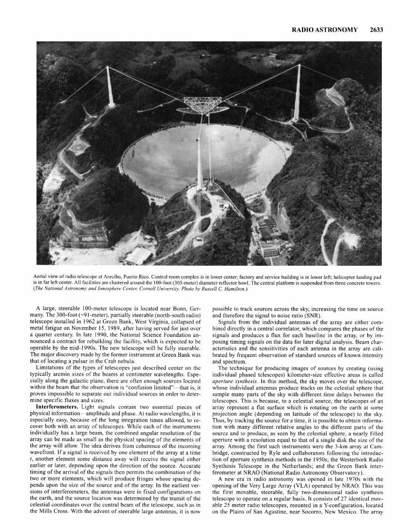
RADIO ASTRONOMY 2633
Aerial view of radio telescope at Arecibo, Puerto Rico. Control room complex is in lower center; factory and service building is in lower left; helicopter landing pad is in far left center. All facilities are clustered around the I 00-foot (305-meter) diameter reflector bowl. The central platform is suspended from three concrete towers . (The National Astronomy and Ionosphere Center, Cornell University. Photo by Russell C. Hamilton.)
A large, steerable l 00-meter telescope is located near Bonn, Germany. The 300-foot ( -91-meter), partially steerable (north-south radio) telescope installed in 1962 at Green Bank, West Virginia, collapsed of metal fatigue on November 15 , 1989, after having served for just over a quarter century. In late 1990, the National Science Foundation announced a contract for rebuilding the facility, which is expected to be operable by the mid-1990s . The new telescope will be fully steerable. The major discovery made by the former instrument at Green Bank was that of locating a pulsar in the Crab nebula.
Limitations of the types of telescopes just described center on the typically arcmin sizes of the beams at centimeter wavelengths. Especially along the galactic plane, there are often enough sources located within the beam that the observation is "confusion limited"- that is , it proves impossible to separate out individual sources in order to determine specific fluxes and sizes.
Interferometers. Light signals contain two essential pieces of physical information- amplitude and phase. At radio wavelengths, it is especially easy, because of the long integration times allowed, to recover both with an array of telescopes. While each of the instruments individually has a large beam, the combined angular resolution of the array can be made as small as the physical spacing of the elements of the array will allow. The idea derives from coherence of the incoming wavefront. If a signal is received by one element of the array at a time t, another element some distance away will receive the signal either earlier or later, depending upon the direction of the source. Accurate timing of the arrival of the signals then permits the combination of the two or more elements, which will produce fringes whose spacing depends upon the size of the source and of the array. In the earliest versions of interferometers, the antennas were in fixed configurations on the earth, and the source location was determined by the transit of the celestial coordinates over the central beam of the telescope, such as in the Mills Cross. With the advent of steerable large antennas, it is now
possible to track sources across the sky, increasing the time on source and therefore the signal to noise ratio (SNR).
Signals from the individual antennas of the array are either combined directly in a central correlator, which compares the phases of the signals and produces a flux for each baseline in the array, or by imposing timing signals on the data for later digital analysis. Beam characteristics and the sensitivities of each antenna in the array are calibrated by frequent observation of standard sources of known intensity and spectrum.
The technique for producing images of sources by creating (using individual phased telescopes) kilometer-size effective areas is called aperture synthesis. In this method, the sky moves over the telescope, whose individual antennas produce tracks on the celestial sphere that sample many parts of the sky with different time delays between the telescopes. This is because, to a celestial source, the telescopes of an array represent a flat surface which is rotating on the earth at some projection angle (depending on latitude of the telescope) to the sky. Thus, by tracking the source for a time, it is possible to obtain information with many different relative angles to the different parts of the source and to produce, as seen by the celestial sphere, a nearly filled aperture with a resolution equal to that of a single disk the size of the array. Among the first such instruments were the 3-km array at Cambridge, constructed by Ryle and collaborators following the introduction of aperture synthesis methods in the 1950s; the Westerbork Radio Synthesis Telescope in the Netherlands; and the Green Bank interferometer at NRAO (National Radio Astronomy Observatory).
A new era in radio astronomy was opened in late 1970s with the opening of the Very Large Array (VLA) operated by NRAO. This was the first movable, steerable, fully two-dimensional radio synthesis telescope to operate on a regular basis. It consists of 27 identical movable 25 meter radio telescopes, mounted in a Y-configuration, located on the Plains of San Agustine, near Socorro, New Mexico. The array
2634 RADIO ASTRONOMY
can be changed from about 3 kilometers to over 30 kilometers by physically transporting the telescopes to different stations along the three arms (24 stations per arm), and can reach a resolution of about 0.1 arcsec, better than most optical telescopes. Because of the ability to vary the ground based spacing of the antennas in the array, the VLA is capable of producing radio images which have nearly circular beams at essentially all positions on the sky accessible from central New Mexico.
The highest angular resolution achieved to date uses Very Long Baseline Interferometry (VLBI). In this technique, radio observers on different continents simultaneously observe a single portion of sky. The signals are later digitally combined. Resolutions of milliarcsec have been obtained, permitting imaging of radio emitting regions on physical size scales as small as light days. A continental size version of the VLA, the Very Long Baseline Array, is being constructed by NRAO using about a dozen identical antennas spread out among sites from Hawaii to Puerto Rico. A project under discussion for the next decade is a spacebased orbiting array of satellite radio telescopes.
Arrays of millimeter telescopes are also possible. Several are currently operating, at Hat Creek in California, Nobayama in Japan, and the !RAM interferometer, currently (1987) under construction in the French Alps. A design study is underway by NRAO for a VLA-like millimeter array, and submillimeter arrays are also being planned. The sizes of these short-wavelength arrays are more severely limited than at longer wavelengths by the turbulence and transparency of the earth's atmosphere and the accuracy required for the telescope surfaces and detectors. They require high, dry, radio-quiet sites.
Types of Radio Emission
The standard unit of radio source strength, the monochromatic flux density, is the Jansky; I Jy = 10~26 W m~2 Hz~ 1 . The strongest radio sources are about I Jy, and the weakest sources thus far detected are at about the microjansky level.
Continuum Emission: Thermal. When protons and electrons undergo near misses in a plasma, photons are emitted as a consequence of the electromagnetic interaction between the charges. The rate of emission increases with increasing temperature and increasing electron density. This radiation is called free-free emission or bremsstrahlung, indicating that it is due to unbound electrons and protons. The spectrum has a characteristic form. The flux density for the optically thin frequencies is almost independent of frequency, but drops steeply at high frequencies (near kT/h where k and h are the Boltzman and Planck constants, respectively, and Tis the source temperature). Thermal spectra turn over at the low frequencies due to optical depth effects internal to the emitting plasma, self-absorption, and have a characteristic low frequency spectrum of Fv - v2, where Fv is the flux density. The source brightness temperature, the temperature a blackbody emitter would need at the same wavelength to achieve the same surface brightness, is essentially the same as the plasma kinetic temperature.
Continuum Emission; Synchrotron. The The most important emission mechanism in radio astrophysics is nonthermal continuum radiation from relativistic electrons spiraling in cosmic magnetic fields. This emission produces a characteristically power law shape, typically Fv -v~ 1, and very high brightness temperatures. The low-frequency spectral cutoff is due to self-absorption, but with a slope different than for thermal radiation, Fv - v2·5. The high-end cutoff is due to the aging of the highest energy electrons, the lifetime of which depends on the magnetic field strength B and the electron energy E, both of which determine the characteristic frequency of the radiated photons. Synchrotron radiation, because it is not thermal in origin, gives information about the most energetic acceleration processes accessible in astrophysical objects. It is both linearly and circularly polarized, the linear polarization providing information about the direction of the magnetic field. Active sources of such emission are solar flares, mass outflows from very high luminosity hot stars, nova and supernova remnants, and especially active galactic nuclei, radio galaxies, and quasars. A low-energy form of this emission is detected from planetary magnetospheres.
21-cm Line of Neutral Hydrogen. The ground state of HI is split due to hyperfine interactions between the nucleus (proton) and elec-
tron, with collisions inducing upward transitions that decay on very long timescales. The prediction that this line would be observable from the diffuse gas of the interstellar medium was published in 1945 by Van de Hulst, who calculated its wavelength as 21 em (1420 MHz). Ewen and Purcell detected the line in emission in 1951, with the first absorption measurement being by Hagen and McClain in 1954. The importance of this radiation is that, because it is discrete, it provides information about both the abundance and velocity of the emitting gas. Using high frequency resolution, of order I to 5 KHz, velocity resolutions of a few kilometers per second can be achieved. As a result, the emission from the diffuse interstellar medium, from the most abundant element in the universe, can be mapped at radio wavelengths at which the galaxy is optically thin. The entire galaxy can be seen in this line, including the regions of the galactic center which are totally obscured at optical and ultraviolet wavelengths.
Recombination Lines. When an electron recombines with an ion, it cascades through the atomic energy levels toward the ground state, emiting photons with each transition. The radiation from the highest levels, near the continuum (the Rydberg states) can be studied at radio wavelengths and provide information about many species heavier than hydrogen, like carbon and helium. In addition, the observation of radio recombination lines of hydrogen gives information about the ionized gas in the same way as the 21-cm line yields a picture of the neutral component. This can be compared directly with continuum radiation (free-free emission) from the same gas and help determine the ionization fraction and dynamics of the ionized medium.
Molecular Lines. Emission from hyperfine structure lines in molecular species, which occur in the millimeter and short centimeter wavelength portion of the spectrum, permit determination of abundances and dynamics for the coldest component of the interstellar medium. Dark clouds are especially productive sources of molecular line emission, which is found in association with regions of star formation. Molecules as complex as HC 11 N have been detected at millimeter frequencies, although the most important probes of the dense cores of the interstellar clouds in which the emission typically arises are molecules like CO, CS, NH3, H2CO, and CN.
Masers. These are a special class of molecular transition, in which the populations of excited levels have been enhanced through collisions and absorption of higher energy photos. The lines produced are both narrow and intense, often having brightness temperatures of millions of degrees. Masers have been detected both from stars and from interstellar clouds. The most important transitions are SiO, H20, OH, and NH3•
See also Telescope.
Additional Reading
Christiansen, W. N., and J. A. Hogden: "Radiotelescopcs," 2nd Ed., Cambridge University Press, New York, 1985.
Cornwell, T. J.: "The Applications of Closure Phase to Astronomical Imaging," Science, 263 (July 21, 1989).
Grossman, A. W., Muhleman, D. 0., and G. L. Berge: "High-Resolution Microwave Images of Saturn," Science, 1211 (September 15, 1989).
Kellermann, K., and B. Sheets: "Serendipitous Discoveries in Radio Astronomy," National Radio Astronomy Observatory, Charlottesville, Virginia, 1983.
Kellermann, K. I, and A. E. Thompson: "The Very-Long-Baseline Array," Sci. Amer., 54 (January 1988).
Kraus, J. D.: "Radio Astronomy," 2nd Ed., Cygnus-Quasar Books, Powell, Ohio, 1986.
Pacholczyk, A.: "Radio Astrophysics," W. H. Freeman, New York, 1970. Rohlfs, K.: "Tools of Radio Astronomy," Springer-Verlag, New York, 1986. Rothman, T.: "In Memoriam: The 300-foot Radio Telescope Has Collapsed," Sci.
Amer., 17 (February 1989). Stone, R.: "Radioastronomers Seek a Clear Line to the Stars," Science, 1316
(March 15, 1991). Sullivan, W. T. Ill, Editor: "The Early Years of Radio Astronomy," Cambridge
University Press, New York, 1984. Thompson, A. R., Moran, J. M., and G. W. Swenson, Jr.: "Interferometry and
Aperture Synthesis in Radio Astronomy," Wiley, New York, 1986. Waldrop, M. M.: "Radio Astronomy's Crumbling Showpiece," Science, 268 (July
19, 1991). Verschuur, G., and K. Kellermann, Editors.: "Galactic and Extragalactic Radio
Astronomy," Springer-Verlag, New York, 1974.
Steven N. Shore
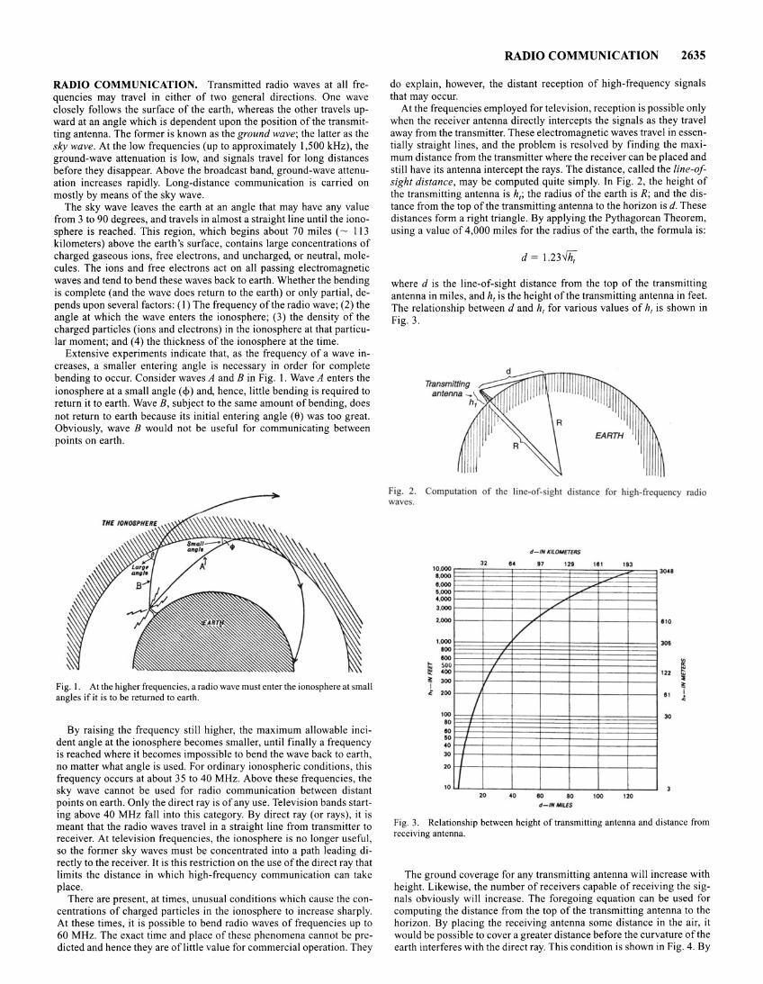
RADIO COMMUNICATION. Transmitted radio waves at all frequencies may travel in either of two general directions. One wave closely follows the surface of the earth, whereas the other travels upward at an angle which is dependent upon the position of the transmitting antenna. The former is known as the ground wave; the latter as the sky wave. At the low frequencies (up to approximately I ,500kHz), the ground-wave attenuation is low, and signals travel for long distances before they disappear. Above the broadcast band, ground-wave attenuation increases rapidly. Long-distance communication is carried on mostly by means of the sky wave.
The sky wave leaves the earth at an angle that may have any value from 3 to 90 degrees, and travels in almost a straight line until the ionosphere is reached. This region, which begins about 70 miles ( - 113 kilometers) above the earth's surface, contains large concentrations of charged gaseous ions, free electrons, and uncharged, or neutral, molecules. The ions and free electrons act on all passing electromagnetic waves and tend to bend these waves back to earth. Whether the bending is complete (and the wave does return to the earth) or only partial, depends upon several factors: (I) The frequency of the radio wave; (2) the angle at which the wave enters the ionosphere; (3) the density of the charged particles (ions and electrons) in the ionosphere at that particular moment; and (4) the thickness of the ionosphere at the time.
Extensive experiments indicate that, as the frequency of a wave increases, a smaller entering angle is necessary in order for complete bending to occur. Consider waves A and B in Fig. 1. Wave A enters the ionosphere at a small angle ( <!>) and, hence, little bending is required to return it to earth. Wave B, subject to the same amount of bending, does not return to earth because its initial entering angle (6) was too great. Obviously, wave B would not be useful for communicating between points on earth.
Fig. I . At the higher frequencies, a radio wave must enter the ionosphere at small angles if it is to be returned to earth.
By raising the frequency still higher, the maximum allowable incident angle at the ionosphere becomes smaller, until finally a frequency is reached where it becomes impossible to bend the wave back to earth, no matter what angle is used. For ordinary ionospheric conditions, this frequency occurs at about 35 to 40 MHz. Above these frequencies, the sky wave cannot be used for radio communication between distant points on earth. Only the direct ray is of any use. Television bands starting above 40 MHz fall into this category. By direct ray (or rays), it is meant that the radio waves travel in a straight line from transmitter to receiver. At television frequencies, the ionosphere is no longer useful , so the former sky waves must be concentrated into a path leading directly to the receiver. It is this restriction on the use of the direct ray that limits the distance in which high-frequency communication can take place.
There are present, at times, unusual conditions which cause the concentrations of charged particles in the ionosphere to increase sharply. At these times, it is possible to bend radio waves of frequencies up to 60 MHz. The exact time and place of these phenomena cannot be predicted and hence they are of little value for commercial operation. They
RADIO COMMUNICATION 2635
do explain, however, the distant reception of high-frequency signals that may occur.
At the frequencies employed for television, reception is possible only when the receiver antenna directly intercepts the signals as they travel away from the transmitter. These electromagnetic waves travel in essentially straight lines, and the problem is resolved by finding the maximum distance from the transmitter where the receiver can be placed and still have its antenna intercept the rays. The distance, called the line-ofsight distance, may be computed quite simply. In Fig. 2, the height of the transmitting antenna is h,; the radius of the earth is R; and the distance from the top of the transmitting antenna to the horizon is d. These distances form a right triangle. By applying the Pythagorean Theorem, using a value of 4,000 miles for the radius of the earth, the formula is:
d = 1.231h;
where d is the line-of-sight distance from the top of the transmitting antenna in miles, and h, is the height of the transmitting antenna in feet. The relationship between d and h, for various values of h, is shown in Fig. 3.
Fig. 2. amputation of the line·of- ight distance for high-frequency radio waves.
32 10.000 e.ooo e.ooo 6.000 4.000
3.000
2.000
1.000 100 100
~ 500 400
l 300 I
/ 1/
"' 200
100 I 10
eo eo 40
30
20
10
J I
20
d-IN K/I.OOifTfRS
14 17 128
./ v
/
40 eo 10 d- INM!US
Ill 113
100 120
3041
110
306
t! 122 ~
" 30
l I ..
Fig. 3. Relationship between height of transmitting antenna and distance from receiving antenna.
The ground coverage for any transmitting antenna will increase with height. Likewise, the number of receivers capable of receiving the signals obviously will increase. The foregoing equation can be used for computing the distance from the top of the transmitting antenna to the horizon. By placing the receiving antenna some distance in the air, it would be possible to cover a greater distance before the curvature ofthe earth interferes with the direct ray. This condition is shown in Fig. 4. By
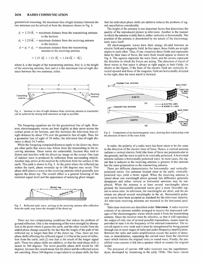
2636 RADIO COMMUNICATION
geometrical reasoning, the maximum line-ofsight distance between the two antennas can be arrived at from the distances shown in Fig. 4.
d 1 = 1.23>1h; = maximum distance from the transmitting antenna to the horizon
d2 = 1.23W/; = maximum distance from the receiving antenna to the horizon
d = d 1 + d2 = maximum distance from the transmitting antenna to the receiving antenna
1.23 >fh; + 1.23W/; = 1.23(>1h; + W/;)
where h, is the height of the transmitting antenna, feet; h, is the height of the receiving antenna, feet; and d is the maximum line-of-sight distance between the two antennas, miles.
~-------------- d --------------~
~----- d~--------~------ d2 ------~
Yh ~h, ,. Receiving Transmitting I '"'antenna antenna~
.:•
Fig. 4. Increase in line-of-sight distance from receiving antenna to transmitter can be achieved by raising both structures as high as possible.
The foregoing equations are for the geometrical line of sight. However, electromagnetic waves are bent slightly as they move across the contact point at the horizon, and this increases the television line-ofsight distance by about 15% over the geometric line of sight. Thus, for a geometric line of sight of 30 miles, the television line-of-sight distance is about 34.5 miles.
While the foregoing computed distances apply to the direct ray, there are other paths that waves may follow from the transmitting to the receiving antennas. These waves are undesirable, because they tend to distort and interfere with the direct-ray image on the screen. One type of indirect wave is produced by reflection from surrounding objects. Another may arrive at the receiver by reflection from the surface of the earth. This path is shown in Fig. 5. At the point where the reflected ray strikes the earth, phase reversals up to 180 degrees may occur. This phase shift places a wave at the receiving antenna which generally acts against the direct ray. The overall effect is a general lowering of the resultant-signal level and the appearance of annoying ghost images.
Direct rav -..... - --+---- --'>--- - -- -~-;;-
'"":a>- d ra.\1 ...... -'"...... j\ecte -~ - ..... ...... ~--_.~
Fig. 5. Reflected radio wave, arriving at the receiving antenna after reflection from the earth, may lower the strength of the direct ray.
There are two compensating conditions that reduce the problem of ground reflection. One is the weakening of the wave strength by absorption at the point where it grazes the earth, and the other results from the added ph'lse change caused by the fact that the length of the path of the reflected ray is longer than that of the direct ray. Thus, there are two phase shifts affecting the reflected signal: (I) One at the point of reflection from the earth; and (2) one that is the result of the longer signal path. These two phase shifts are additive, so that the total phase shift is nearer to 360 degrees. The worst possible phase shift would be 180 degrees, because this would mean that the direct and the reflected waves are canceling. Since 360 degrees is equivalent to no phase shift, the fact
that the individual phase shifts are additive reduces the problem of signal cancellation considerably.
The height of the antenna is one important factor that determines the quality of the reproduced picture in television. Another is the manner in which the antenna is held, that is, either vertically or horizontally. The position of the antenna is determined by the nature of the electromagnetic wave itself.
All electromagnetic waves have their energy divided between an electric field and a magnetic field. In free space, these fields are at right angles to each other. Thus, if one visualizes these fields and represents them by their lines of force, the wave front would appear as shown in Fig. 6. The squares represent the wave front, and the arrows represent the direction in which the forces are acting. The direction of travel of these waves in free space is always at right angles to both fields. As shown in the figure, if the lines of the electric field are vertically directed upward and those of the magnetic field are horizontally directed to the right, then the wave travel is forward.
(A ) - ELECTRIC LINES
Fig. 6. Components of an electromagnetic wave, showing their relationship with the direction of travel of the wave form.
In radio, the polarity of a radio wave has been taken to be the same as the direction of the electric lines of force. Hence, a vertical antenna radiates a vertical electric field (the lines of force are perpendicular to the ground), and the wave is said to be vertically polarized. A horizontal antenna radiates a horizontally-polarized wave. In most cases, the signal that is induced in the receiving antenna is greatest if this antenna has the same polarization as the transmitting antenna.
There are different characteristics for horizontally- and verticallypolarized waves. For antennas located close to the earth, verticallypolarized rays yield a better signal. When the receiving antenna is raised about one wavelength above ground, this difference generally disappears and either vertical or horizontal antennas may be employed. When the antenna is at least several wavelengths above ground, the horizontally-polarized waves give a more favorable signal-to-noise ratio. In television, the wavelengths are short, and the antennas are placed several wavelengths in the air. Horizontally-polarized waves have been accepted as standard for the television industry. All television receiving antennas are mounted in the horizontal position.
Television receivers are described under Television. A radio receiver consists of an antenna suitably arranged to receive the impressed voltages of the electromagnetic waves which reach it from the transmitting antenna. Since the receiver must be selective, so that it will reproduce the output of only one of several possible transmitters, means must be provided to tune it to the frequency of the selected transmitter. The received signal is very weak and it must be strengthened by being passed through one or more stages of radio and audio-frequency amplification. Between the radio and audio amplification occurs the action of detection, or demodulation, separating the carried wave from the electrical wave which mirrors the original voice or sound wave. Finally, the amplified voice current is fed into a speaker which re-creates the original sound.
The precursor of current AM radio receivers was the superheterodyne, developed by Armstrong in the early 1920s. This basic circuit
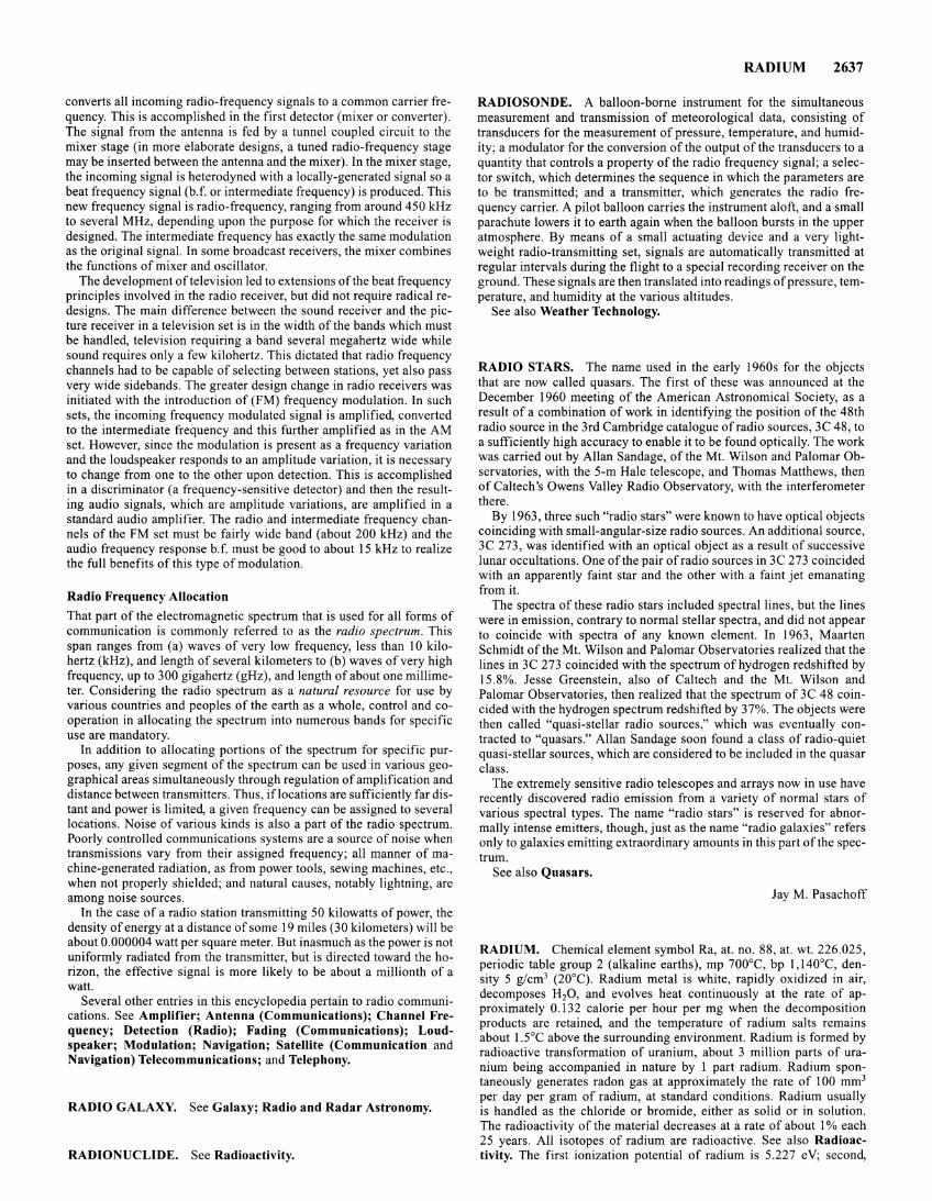
converts all incoming radio-frequency signals to a common carrier frequency. This is accomplished in the first detector (mixer or converter). The signal from the antenna is fed by a tunnel coupled circuit to the mixer stage (in more elaborate designs, a tuned radio-frequency stage may be inserted between the antenna and the mixer). In the mixer stage, the incoming signal is heterodyned with a locally-generated signal so a beat frequency signal (b. f. or intermediate frequency) is produced. This new frequency signal is radio-frequency, ranging from around 450kHz to several MHz, depending upon the purpose for which the receiver is designed. The intermediate frequency has exactly the same modulation as the original signal. In some broadcast receivers, the mixer combines the functions of mixer and oscillator.
The development of television led to extensions of the beat frequency principles involved in the radio receiver, but did not require radical redesigns. The main difference between the sound receiver and the picture receiver in a television set is in the width of the bands which must be handled, television requiring a band several megahertz wide while sound requires only a few kilohertz. This dictated that radio frequency channels had to be capable of selecting between stations, yet also pass very wide sidebands. The greater design change in radio receivers was initiated with the introduction of (FM) frequency modulation. In such sets, the incoming frequency modulated signal is amplified, converted to the intermediate frequency and this further amplified as in the AM set. However, since the modulation is present as a frequency variation and the loudspeaker responds to an amplitude variation, it is necessary to change from one to the other upon detection. This is accomplished in a discriminator (a frequency-sensitive detector) and then the resulting audio signals, which are amplitude variations, are amplified in a standard audio amplifier. The radio and intermediate frequency channels of the FM set must be fairly wide band (about 200 kHz) and the audio frequency response b.f. must be good to about 15kHz to realize the full benefits of this type of modulation.
Radio Frequency Allocation
That part of the electromagnetic spectrum that is used for all forms of communication is commonly referred to as the radio spectrum. This span ranges from (a) waves of very low frequency, less than 10 kilohertz (kHz), and length of several kilometers to (b) waves of very high frequency, up to 300 gigahertz (gHz), and length of about one millimeter. Considering the radio spectrum as a natural resource for use by various countries and peoples of the earth as a whole, control and cooperation in allocating the spectrum into numerous bands for specific use are mandatory.
In addition to allocating portions of the spectrum for specific purposes, any given segment of the spectrum can be used in various geographical areas simultaneously through regulation of amplification and distance between transmitters. Thus, iflocations are sufficiently far distant and power is limited, a given frequency can be assigned to several locations. Noise of various kinds is also a part of the radio spectrum. Poorly controlled communications systems are a source of noise when transmissions vary from their assigned frequency; all manner of machine-generated radiation, as from power tools, sewing machines, etc., when not properly shielded; and natural causes, notably lightning, are among noise sources.
In the case of a radio station transmitting 50 kilowatts of power, the density of energy at a distance of some 19 miles (30 kilometers) will be about 0.000004 watt per square meter. But inasmuch as the power is not uniformly radiated from the transmitter, but is directed toward the horizon, the effective signal is more likely to be about a millionth of a watt.
Several other entries in this encyclopedia pertain to radio communications. See Amplifier; Antenna (Communications); Channel Frequency; Detection (Radio); Fading (Communications); Loudspeaker; Modulation; Navigation; Satellite (Communication and Navigation) Telecommunications; and Telephony.
RADIO GALAXY. See Galaxy; Radio and Radar Astronomy.
RADIONUCLIDE. See Radioactivity.
RADIUM 2637
RADIOSONDE. A balloon-borne instrument for the simultaneous measurement and transmission of meteorological data, consisting of transducers for the measurement of pressure, temperature, and humidity; a modulator for the conversion of the output of the transducers to a quantity that controls a property of the radio frequency signal; a selector switch, which determines the sequence in which the parameters are to be transmitted; and a transmitter, which generates the radio frequency carrier. A pilot balloon carries the instrument aloft, and a small parachute lowers it to earth again when the balloon bursts in the upper atmosphere. By means of a small actuating device and a very lightweight radio-transmitting set, signals are automatically transmitted at regular intervals during the flight to a special recording receiver on the ground. These signals are then translated into readings of pressure, temperature, and humidity at the various altitudes.
See also Weather Technology.
RADIO STARS. The name used in the early 1960s for the objects that are now called quasars. The first of these was announced at the December 1960 meeting of the American Astronomical Society, as a result of a combination of work in identifying the position of the 48th radio source in the 3rd Cambridge catalogue of radio sources, 3C 48, to a sufficiently high accuracy to enable it to be found optically. The work was carried out by Allan Sandage, of the Mt. Wilson and Palomar Observatories, with the 5-m Hale telescope, and Thomas Matthews, then of Caltech's Owens Valley Radio Observatory, with the interferometer there.
By 1963, three such "radio stars" were known to have optical objects coinciding with small-angular-size radio sources. An additional source, 3C 273, was identified with an optical object as a result of successive lunar occultations. One of the pair of radio sources in 3C 273 coincided with an apparently faint star and the other with a faint jet emanating from it.
The spectra of these radio stars included spectral lines, but the lines were in emission, contrary to normal stellar spectra, and did not appear to coincide with spectra of any known element. In 1963, Maarten Schmidt of the Mt. Wilson and Palomar Observatories realized that the lines in 3C 273 coincided with the spectrum of hydrogen redshifted by 15.8%. Jesse Greenstein, also of Caltech and the Mt. Wilson and Palomar Observatories, then realized that the spectrum of 3C 48 coincided with the hydrogen spectrum redshifted by 37%. The objects were then called "quasi-stellar radio sources," which was eventually contracted to "quasars." Allan Sandage soon found a class of radio-quiet quasi-stellar sources, which are considered to be included in the quasar class.
The extremely sensitive radio telescopes and arrays now in use have recently discovered radio emission from a variety of normal stars of various spectral types. The name "radio stars" is reserved for abnormally intense emitters, though, just as the name "radio galaxies" refers only to galaxies emitting extraordinary amounts in this part of the spectrum.
See also Quasars.
Jay M. Pasachoff
RADIUM. Chemical element symbol Ra, at. no. 88, at. wt. 226.025, periodic table group 2 (alkaline earths), mp 700°C, bp 1,140°C, density 5 g/cm3 (20°C). Radium metal is white, rapidly oxidized in air, decomposes H20, and evolves heat continuously at the rate of approximately 0.132 calorie per hour per mg when the decomposition products are retained, and the temperature of radium salts remains about 1.5°C above the surrounding environment. Radium is formed by radioactive transformation of uranium, about 3 million parts of uranium being accompanied in nature by 1 part radium. Radium spontaneously generates radon gas at approximately the rate of 100 mm3
per day per gram of radium, at standard conditions. Radium usually is handled as the chloride or bromide, either as solid or in solution. The radioactivity of the material decreases at a rate of about l% each 25 years. All isotopes of radium are radioactive. See also Radioactivity. The first ionization potential of radium is 5.227 eV; second,
2638 RADIX POINT
10.099 eV Other important physical properties of radium are given under Chemical Elements.
One year after the discovery of x-rays by Rontgen (1895), Henri Becquerel investigated the relationship between the phosphorescence of various salts after their exposure to sunlight and the fluorescence in an operating x-ray tube. One of the salts under investigation was potassium-uranium sulfate. After exposure to sunlight, Becquerel noted that the salt not only emitted visible light, but also rays similar to xrays that were able to penetrate the heavy black paper and thin metal foils within which his photographic plates were wrapped. During aperiod of cloudy weather, Becquerel stored the salt and photographic plates in a closet, awaiting further sunny days. Later, when he inspected the package, he noted that a very intense image had been developed on the photographic plate even though it had not received much prior exposure to sunlight. By further experiments, Becquerel confirmed that the intense image was derived directly from the presence of the salt, regardless of any exposure to sunlight. This constituted the first demonstration of radioactivity. Through further investigations, Ernest Rutherford demonstrated that both alpha and beta radiations were emitted by the salt. Rutherford learned that the alpha rays were easily absorbed by thin sheets of paper, whereas the beta rays acted in the same manner as observed by Becquerel. Later Mme. Marie Curie found that thorium produced about the same intensity of radioactivity as uranium. Further tests disclosed that the uranium ore with which she was working (pitchblende) exhibited more radioactivity than could be accounted for by its uranium content alone. Subsequently, Mme. Curie and her husband, Pierre Curie, successfully separated two previously unknown elements, radium and polonium. Thus, both radium and polonium were identified as chemical elements in 1898. It was found that each of these elements was over a million times more radioactive than uranium.
Radium gained prominence not only from its scientific interest, heralding a whole new area of physics and chemistry, but from its wide use in therapeutic medicine, as an ingredient (very dangerous) of luminous paints, and in various instruments for inspecting structures, such as metal castings. Commercially, radium generally is marketed as the bromide or sulfate and is extremely radioactive in these forms. Use of radium in medical technology has largely been replaced by other sources of radioactivity.
Radium occurs in pitchblende, and in carnotite along with uranium. Radium was first obtained from the uranium residues of pitchblende of Joachimsthal, the Czech Republic and Slovakia, later from carnotite of southwestern Colorado and eastern Utah. Richer ores have been found in Republic of Congo and in the Great Bear region of northwestern Canada.
In an interesting narrative, Landa ( 1979) describes and depicts what the author calls the "first nuclear industry," one that flourished during the first third of the 20th century. At that time, the prized element was not uranium, but rather it was radium. Radium initiated the concept of radiotherapy for the treatment of cancerous tumors. Even at the peak of radium production no more than a few hundred grams per year were purified. At one time the price approached $180,000 per gram (in early 1900s dollars). In one large extraction plant located in Denver, Colorado (National Radium Institute), carnotite ore was processed by a direct-dissolution method. During the three years (1914-1916) this plant was in operation, only 8.5 grams of Ra had been purified at an average cost of about $38,000 per gram. Pitchblende deposits from the Haut Katanga district of the Belgian Congo were discovered, but because of World War I, were not commericially exploited until 1921. Whereas it previously had required between 300 and 400 tons of a typical American carnotite ore to produce one gram of Ra, less than ten tons of the Kantanga ore were required. In 1931, an extraction plant at Port Hope, Ontario, designed to process uranium found in outcrops along the shores of Great Bear Lake in northwestern Canada, was commissioned. The hazards of radium production and handling were slow to surface and were not seriously recognized until the 1920s after a report had been prepared which implicated the ingestion of Ra in jaw necrosis in radium dial painters and lung cancer in uranium miners. Several workers, possibly including Marie Curie, died of conditions that were probably the result oflong-term radiation exposure. By the 1930s, nuemrous precautions were initiated, including the design of tunnels at the Great Bear Lake mines to minimize radon hazards to miners.
The radium isotope of mass number 226 occurs in the uranium (2n + 2) alpha-decay series. Its half-life is 1,620 years, and it yields radon-222 by a-disintegration. Other naturally occurring isotopes of radium are 228Ra in the thorium series, half-life 6.7 years, producing actinium-228 by fjdecay, which yeilds by fjdecay thorium-228, which in turn yields 224Ra, half-life 3.64 days, giving radon-220 by o.-decay. Another naturally, occurring isotope of radium is found in the actinium series; it is 223Ra, half-life 11.7 days, giving radon-219 by o.-decay. In the neptunium series there is 225Ra, half-life 14.8 days, undergoing [3-decay to actinium-225. Other isotopes of radium include those of mass numbers 219,221,225,227,229, and 230.
Chemically related to barium, radium is recovered from its ores by addition of barium salt, followed by treatment as for recovery of barium, usually as the sulfate. The sulfates of barium and of radium are insoluble in most chemicals, so they are transformed into carbonate or sulfide, both of which are readily soluble in HCI. Separation from barium is accomplished by fractional crystallization of the chlorides (or bromides, or hydroxides). Dry, concentrated radium salts are preserved in sealed glass tubes, which are periodically opened by experienced workers to relieve the pressure. The glass tubes are kept in lead shields.
In many of its chemical properties, radium is like the elements magnesium, calcium, strontium and barium, and it is placed in group 2, as is consistent with its 6s26p67 s2 electron configuration. Its sulfate (K,P = 4.2 X 10- 15) is even more insoluble in water than barium sulfate, with which it is conveniently coprecipitated. Like barium and other alkaline earth metals, it forms a soluble chloride (K,P = 0.4) and bromide, which can also be obtained as dihydrates. Radium also resembles the other group 2 elements in forming an insoluble carbonate and a very slightly soluble iodate (K,P = 8.8 X 10- 10).
Additional Reading
Landa, E. R.: "The First Nuclear Industry," Sci. Amer., 180 (November 1982). Sax, N. R., and R. J. Lewis, Sr.: "Dangerous Properties of Industrial Materials,"
8th Edition, Van Nostrand Reinhold, New York, 1992. Staff: "Handbook of Chemistry and Physics," 73rd Edition, CRC Press, Boca
Raton, Florida, 1992-1993. Williams, P. L., and J. L. Burson, Editors: "Industrial Toxicology," Van Nostrand
Reinhold, New York, 1989.
RADIX POINT. The index which separates the digits associated with negative powers from those associated with the zero and positive powers of the base of the number system in which a quantity is represented; i.e., binary point, decimal point.
RADOME. A dome used to cover the antenna assembly of a radar to protect it from wind and weather. The term may refer to either a surface or airborne installation. Radomes must be made of a material that is transparent to radio energy.
RADON. Chemical element symbol Rn, at. no. 86, at. wt. 222 (mass number of the most stable isotope), periodic table group 18 (inert gases), mp -71°C, bp -61.8°C. First ionization potential, 10.745 eV Density 9.72 g/1(0°C, 760 torr), 7.5 X more dense than air. The gas has been liquefied at -65°C and solidified at -11 0°C. Radon was first isolated by Ramsay and Gray in 1908. Prior to acceptance of the present designation, radon was called niton or radium emanation. See also Radioactivity.
222Rn is formed by the alpha disintegration of 226Ra. Actinon, its isotope of mass number 219, is produced by alpha disintegration of 223 Ra (AcX) and is a member of the Actinium Series. Similarly, thoron, its isotope of mass number 220, is a member of the thorium series. Since the name "radon" may be considered to be specific for the isotope of mass number 222 (from the radium series), the term "emanation" is sometimes used for element number 86 in general. Other isotopes of radon include those of mass numbers 209-218 and 221.
A fluorine compound of radon has been formed by reaction of the elements under higher temperature and pressure, similar to the conditions for forming xenon fluorides. Radon forms a hydrate of atmospheric pressure at 0°C. It forms a compound with phenol, Rn·2C6H50H
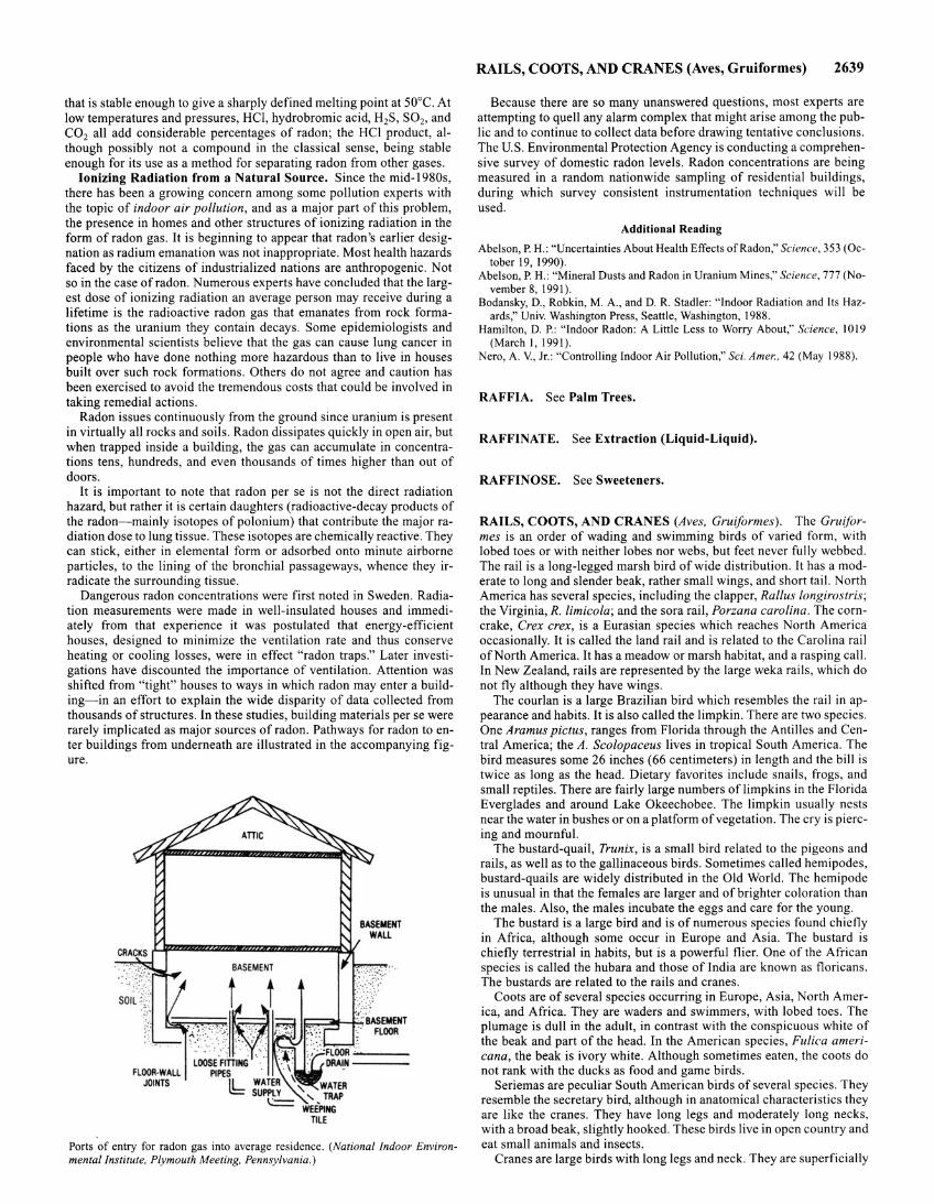
that is stable enough to give a sharply defined melting point at 50°C. At low temperatures and pressures, HCl, hydrobromic acid, H2S, S02, and C02 all add considerable percentages of radon; the HCl product, although possibly not a compound in the classical sense, being stable enough for its use as a method for separating radon from other gases.
Ionizing Radiation from a Natural Source. Since the mid-1980s, there has been a growing concern among some pollution experts with the topic of indoor air pollution, and as a major part of this problem, the presence in homes and other structures of ionizing radiation in the form of radon gas. It is beginning to appear that radon's earlier designation as radium emanation was not inappropriate. Most health hazards faced by the citizens of industrialized nations are anthropogenic. Not so in the case of radon. Numerous experts have concluded that the largest dose of ionizing radiation an average person may receive during a lifetime is the radioactive radon gas that emanates from rock formations as the uranium they contain decays. Some epidemiologists and environmental scientists believe that the gas can cause lung cancer in people who have done nothing more hazardous than to live in houses built over such rock formations. Others do not agree and caution has been exercised to avoid the tremendous costs that could be involved in taking remedial actions.
Radon issues continuously from the ground since uranium is present in virtually all rocks and soils. Radon dissipates quickly in open air, but when trapped inside a building, the gas can accumulate in concentrations tens, hundreds, and even thousands of times higher than out of doors.
It is important to note that radon per se is not the direct radiation hazard, but rather it is certain daughters (radioactive-decay products of the radon- mainly isotopes of polonium) that contribute the major radiation dose to lung tissue. These isotopes are chemically reactive. They can stick, either in elemental form or adsorbed onto minute airborne particles, to the lining of the bronchial passageways, whence they irradicate the surrounding tissue.
Dangerous radon concentrations were first noted in Sweden. Radiation measurements were made in well-insulated houses and immediately from that experience it was postulated that energy-efficient houses, designed to minimize the ventilation rate and thus conserve heating or cooling losses, were in effect "radon traps." Later investigations have discounted the importance of ventilation. Attention was shifted from "tight" houses to ways in which radon may enter a building-in an effort to explain the wide disparity of data collected from thousands of structures. In these studies, building materials per se were rarely implicated as major sources of radon. Pathways for radon to enter buildings from underneath are illustrated in the accompanying figure.
Fl OOR·WALL JOINTS
Ports of entry for radon gas into average residence. (National Indoor Environmental Institute, Plymouth Meeting, Pennsylvania .)
RAILS, COOTS, AND CRANES (Aves, Gruiformes) 2639
Because there are so many unanswered questions, most experts are attempting to quell any alarm complex that might arise among the public and to continue to collect data before drawing tentative conclusions. The U.S. Environmental Protection Agency is conducting a comprehensive survey of domestic radon levels. Radon concentrations are being measured in a random nationwide sampling of residential buildings, during which survey consistent instrumentation techniques will be used.
Additional Reading
Abelson, P. H.: "Uncertainties About Health Effects of Radon," Science, 353 (October 19, 1990).
Abelson, P. H.: "Mineral Dusts and Radon in Uranium Mines," Science, 777 (November 8, 1991).
Bodansky, D., Rabkin, M. A. , and D. R. Stadler: "Indoor Radiation and Its Hazards," Univ. Washington Press, Seattle, Washington, 1988.
Hamilton, D.P.: "Indoor Radon: A Little Less to Worry About," Science, 1019 (March I , 1991).
Nero, A. V., Jr.: "Controlling Indoor Air Pollution," Sci. A mer., 42 (May 1988).
RAFFIA. See Palm Trees.
RAFFINATE. See Extraction (Liquid-Liquid).
RAFFINOSE. See Sweeteners.
RAILS, COOTS, AND CRANES (Aves, Gruiformes). The Gruiformes is an order of wading and swimming birds of varied form, with lobed toes or with neither lobes nor webs, but feet never fully webbed. The rail is a long-legged marsh bird of wide distribution. It has a moderate to long and slender beak, rather small wings, and short tail. North America has several species, including the clapper, Rallus /ongirostris; the Virginia, R. limicola; and the sora rail, Porzana carolina. The corncrake, Crex crex, is a Eurasian species which reaches North America occasionally. It is called the land rail and is related to the Carolina rail ofNorth America. It has a meadow or marsh habitat, and a rasping call. In New Zealand, rails are represented by the large weka rails, which do not fly although they have wings.
The courlan is a large Brazilian bird which resembles the rail in appearance and habits. It is also called the limpkin. There are two species. One Aramus pictus, ranges from Florida through the Antilles and Central America; the A. Scolopaceus lives in tropical South America. The bird measures some 26 inches (66 centimeters) in length and the bill is twice as long as the head. Dietary favorites include snails, frogs, and small reptiles. There are fairly large numbers of limpkins in the Florida Everglades and around Lake Okeechobee. The limpkin usually nests near the water in bushes or on a platform of vegetation. The cry is piercing and mournful.
The bustard-quail, Trunix, is a small bird related to the pigeons and rails, as well as to the gallinaceous birds. Sometimes called hemipodes, bustard-quails are widely distributed in the Old World. The hemipode is unusual in that the females are larger and of brighter coloration than the males. Also, the males incubate the eggs and care for the young.
The bustard is a large bird and is of numerous species found chiefly in Africa, although some occur in Europe and Asia. The bustard is chiefly terrestrial in habits, but is a powerful flier. One of the African species is called the hubara and those of India are known as floricans. The bustards are related to the rails and cranes.
Coots are of several species occurring in Europe, Asia, North America, and Africa. They are waders and swimmers, with lobed toes. The plumage is dull in the adult, in contrast with the conspicuous white of the beak and part of the head. In the American species, Fulica americana, the beak is ivory white. Although sometimes eaten, the coots do not rank with the ducks as food and game birds.
Seriemas are peculiar South American birds of several species. They resemble the secretary bird, although in anatomical characteristics they are like the cranes. They have long legs and moderately long necks, with a broad beak, slightly hooked. These birds live in open country and eat small animals and insects.
Cranes are large birds with long legs and neck. They are superficially
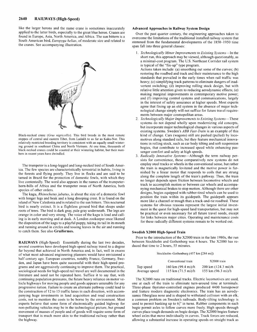
2640 RAILWAYS (High-Speed)
like the larger herons and the name crane is sometimes inaccurately applied to the latter birds, especially to the great blue heron. Cranes are found in Europe, Asia, North America, and Africa. The sun bittern is a South American bird, Europyga helias, of moderate size and related to the cranes. See accompanying illustration.
Black-necked crane ( Grus nigricollis). This bird breeds in the most remote steppes of central and eastern Tibet, from Ladakh to as far as Kuku-Nor. This relatively restricted breeding territory is consistent with an equally small wintering ground in southeast China and North Vietnam. At one time, thousands of black-necked cranes could be counted at their wintering habitat, but their numbers in recent years have dwindled.
The trumpeter is a long-legged and long-necked bird of South America. The few species are characteristically terrestrial in habits, living in the forests and flying poorly. They live in flocks and are said to be tamed in Brazil for the protection of domestic fowls, with which they live contentedly. The word also appears in the names of the trumpeterhorn-bills of Africa and the trumpeter swan of North America, both species of other orders.
The kagu, Rhinochetus jubatus, is about the size of a domestic fowl with longer legs and beak and a long drooping crest. It is found on the island of New Caledonia and is related to the sun bittern. This nocturnal bird is nearly extinct. It is a flightless ground bird that sleeps under roots of trees. The bird is dark gray, pale gray underneath. The legs are orange in color and very strong. The voice of the kagu is loud and calling is in early morning and at dusk. A London zookeeper once likened the disposition of the kagu to a playful puppy, taking its tail in its mouth and running around in circles and tossing leaves in the air and running to catch them. See also Gruiformes.
RAILWAYS (High-Speed) Essentially during the last two decades, several countries have developed high-speed railway travel to a degree far beyond that achieved in North America and, in fact, well in excess of what most advanced engineering planners would have envisioned a half century ago. European countries, notably France, Germany, Sweden, and Japan have been quite successful with their high-speed programs and are aggressively continuing to improve them. The practical, sociological needs for high-speed rail travel are well documented in the literature and need not be repeated here. Suffice it to say that, with continuing population pressures, the future heavy reliance on motor vehicle highways for moving people and goods appears untenable for any progressive nation. Failure to create an alternate pathway could lead to the construction of 12 to 15 traffic lanes in each direction, with accompanying huge investments in land acquisition and road construction costs, not to mention the costs to be borne by the environment. Most experts believe that some form of electronically guided highway for non-polluting vehicles may be in the technological picture, but ground movement of masses of people and of goods will require some form of transport that is much more akin to the traditional railway rather than the highway.
Advanced Approaches in Railway System Design
Over the past quarter century, the engineering approaches taken to overcome the limitations of the traditional installed railway system that stemmed from the fundamental developments of the 1850-1950 time span fall into three general classes:
I. Technologically Minor Improvements to Existing S:ystems-ln the short run, this approach may be viewed, although questionably, as a minimal-cost program. The U.S. Northeast Corrider rail system is typical of the "fix-up" type program. Actions taken include: (a) smoothing out some of the curves; (b) restoring the roadbed and track and their maintenance to the high standards that prevailed in the early times when rail traffic was heavy; (c) simplifying track patterns to eliminate dangers of inadvertent switching; (d) improving rolling stock design, but with relative little attention given to reducing aerodynamic effects; (e) making marginal improvements in contemporary motive power; and (f) improving control systems and communications, largely in the interest of safety assurance at higher speeds. Most experts agree that fixing up an old system in the absence of major technological change simply will not suffice for future travel requirements between major cosmopolitan areas.
2. Technologically Major Improvements to Existing Systems-These systems do not depend wholly upon modernizing old concepts, but incorporate major technological changes in various aspects of existing systems. Sweden's ABB Fast-Train is an example of this kind of change. Cars (wagons) still are pushed (pulled) by locomotives along standard rails, but they feature mechanical innovations in rolling stock, such as car body tilting and soft suspension bogies, that contribute to increased speed while enhancing passenger comfort and safety at high speeds.
3. Radically Innovative Systems-Although the term railway persists for convenience, these comparatively new systems do not employ steel tracks or wheels in the conventional sense, but rather the train is magnetically levitated and the motive power is furnished by a linear motor that responds to coils that are strung along the complete length of the train's pathway. Thus, the train no longer depends upon friction between locomotive wheels and track to accomplish motion or between car wheels and accompanying mechanical brakes to stop motion. Although there are other designs, bogies equipped with rubber-tired wheels can be used to position the train within its guidepath. The guidepath appears more like a channel or trough than a track-and-tie roadbed. These systems for obvious reasons represent the largest initial investment in the quest for high-speed land transportation, but may not be practical or even necessary for all future travel needs, except for links between major cities. Operating and maintenance costs for these radically different systems remain to be worked out.
Swedish X2000 High-Speed Train
Prior to the introduction of the X2000 train in the late I 980s, the run between Stockholm and Gothenberg was 4 hours. The X2000 has reduced that time to 2 hours, 55 minutes.
Stockholm-Gothenburg (457 km [284 mi])
Top speed Average speed
Conventional train
160 km (99.4 mi)/h 115 km (71.5 mi)/h
X2000 train
200 km ( 124.3 mi)/h 155 km (96.3 mi)/h
The X2000 runs on traditional tracks. Electric locomotives are used, one at each of the train to eliminate turn-around time at terminals. Three-phase thyristor-controlled engines produced 4400 horsepower and feature modern diagnostic electronics. The train has an aerodynamic fiberglass nose and is shaped to withstand collision with an elk, a common problem on Sweden's railroads. Body-tilting technology is used to permit banking up to 6~0 in turns. Rubber components in each bogie permit axles to follow curves more freely. High speeds through curves place tough demands on bogie design. The X2000 bogies feature wheel axles that move individually in curves. Track forces are reduced, allowing a substantial increase in operating speeds on straight track as
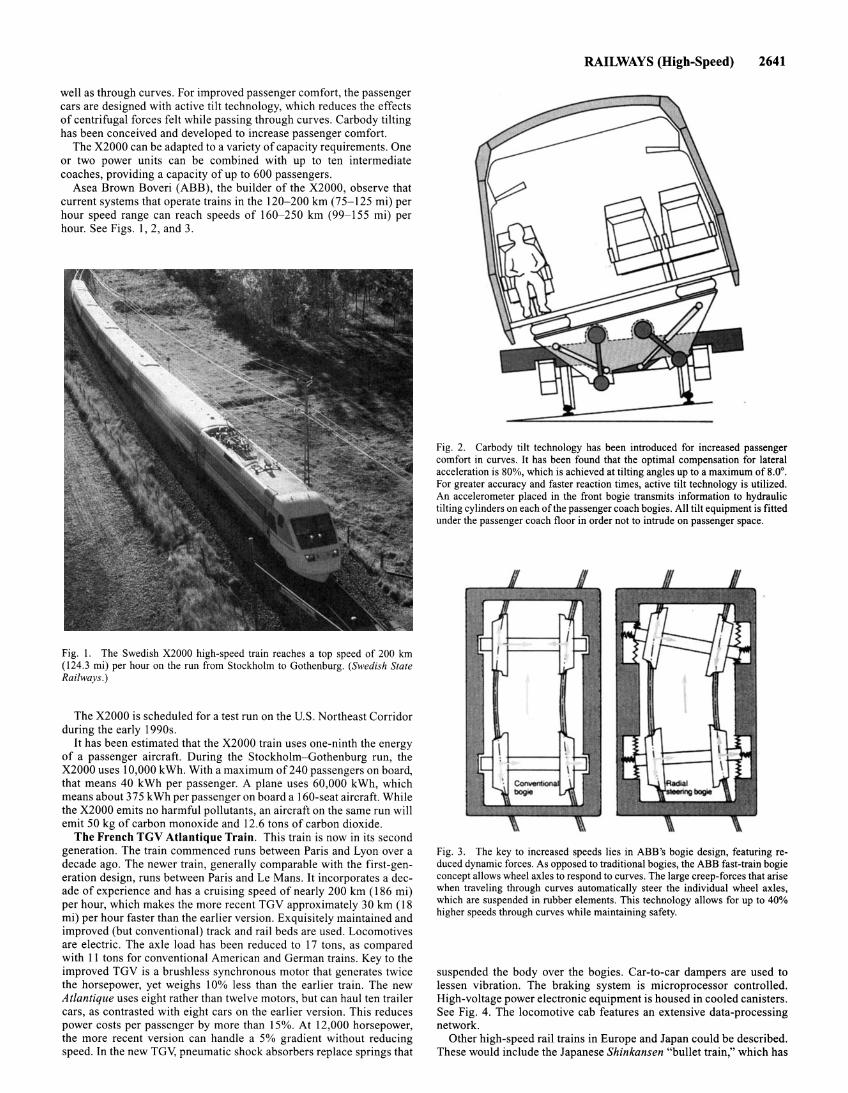
well as through curves. For improved passenger comfort, the passenger cars are designed with active tilt technology, which reduces the effects of centrifugal forces felt while passing through curves. Carbody tilting has been conceived and developed to increase passenger comfort.
The X2000 can be adapted to a variety of capacity requirements. One or two power units can be combined with up to ten intermediate coaches, providing a capacity of up to 600 passengers.
Asea Brown Boveri (ABB), the builder of the X2000, observe that current systems that operate trains in the 120-200 km (75-125 mi) per hour speed range can reach speeds of 160-250 km (99-155 mi) per hour. See Figs. I, 2, and 3.
Fig. I. The Swedish X2000 high-speed train reaches a top speed of 200 km (124.3 mi) per hour on the run from Stockholm to Gothenburg. (Swedish State Railways.)
The X2000 is scheduled for a test run on the U.S. Northeast Corridor during the early 1990s.
It has been estimated that the X2000 train uses one-ninth the energy of a passenger aircraft. During the Stockholm-Gothenburg run, the X2000 uses I 0,000 kWh. With a maximum of240 passengers on board, that means 40 kWh per passenger. A plane uses 60,000 kWh, which means about 375 kWh per passenger on board a 160-seat aircraft. While the X2000 emits no harmful pollutants, an aircraft on the same run will emit 50 kg of carbon monoxide and 12.6 tons of carbon dioxide.
The French TGV Atlantique Train. This train is now in its second generation. The train commenced runs between Paris and Lyon over a decade ago. The newer train, generally comparable with the first-generation design, runs between Paris and Le Mans. It incorporates a decade of experience and has a cruising speed of nearly 200 km ( 186 mi) per hour, which makes the more recent TGV approximately 30 km (18 mi) per hour faster than the earlier version. Exquisitely maintained and improved (but conventional) track and rail beds are used. Locomotives are electric. The axle load has been reduced to 17 tons, as compared with II tons for conventional American and German trains. Key to the improved TGV is a brushless synchronous motor that generates twice the horsepower, yet weighs 10% less than the earlier train. The new Atlantique uses eight rather than twelve motors, but can haul ten trailer cars, as contrasted with eight cars on the earlier version. This reduces power costs per passenger by more than 15%. At 12,000 horsepower, the more recent version can handle a 5% gradient without reducing speed. In the new TGV, pneumatic shock absorbers replace springs that
RAILWAYS (High-Speed) 2641
Fig. 2. Carbody tilt technology has been introduced for increased passenger comfort in curves. It has been found that the optimal compensation for lateral acceleration is 80%, which is achieved at tilting angles up to a maximum of 8.0°. For greater accuracy and faster reaction times, active tilt technology is utilized. An accelerometer placed in the front bogie transmits information to hydraulic tilting cylinders on each of the passenger coach bogies. All tilt equipment is fitted under the passenger coach floor in order not to intrude on passenger space.
Fig. 3. The key to increased speeds lies in ABB's bogie design, featuring reduced dynamic forces. As opposed to traditional bogies, the ABB fast-train bogie concept allows wheel axles to respond to curves. The large creep-forces that arise when traveling through curves automatically steer the individual wheel axles, which are suspended in rubber elements. This technology allows for up to 40% higher speeds through curves while maintaining safety.
suspended the body over the bogies. Car-to-car dampers are used to lessen vibration. The braking system is microprocessor controlled. High-voltage power electronic equipment is housed in cooled canisters. See Fig. 4. The locomotive cab features an extensive data-processing network.
Other high-speed rail trains in Europe and Japan could be described. These would include the Japanese Shinkansen "bullet train," which has
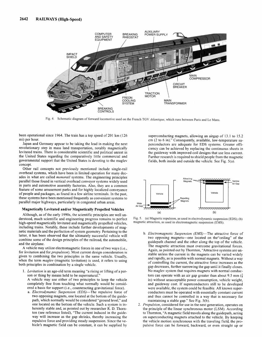
2642 RAILWAYS (High-Speed)
Fig. 4. chematic diagram of forward locomotive u ed on the French TGV Atlamique, which runs between Paris and LeMan .
been operational since 1964. The train has a top speed of 20 I km (126 mi) per hour.
Japan and Germany appear to be taking the lead in making the next revolutionary step in mass land transportation, notably magnetically levitated trains. There is considerable scientific and political unrest in the United States regarding the comparatively little commercial and governmental support that the United States is devoting to the maglev concept.
Other rail concepts not previously mentioned include single-rail overhead systems, which have been in limited operation for many decades in what are called monorail systems. The engineering principles parallel those found in vertical overhead conveyor systems widely used in parts and automotive assembly factories. Also, they are a common feature of some amusement parks and for highly localized conveyance of people and packages, as found in a few airline terminals. In the past, these systems have been mentioned frequently as convenient systems to parallel major highways, particularly in congested urban areas.
Magnetically Levitated and/or Magnetically Propelled Vehicles Although, as of the early 1990s, the scientific principles are well un
derstood, much scientific and engineering progress remains to perfect high-speed magnetically levitated and magnetically propelled vehicles, including trains. Notably, these include further developments of magnetic materials and the perfection of system geometry. Pertaining to the latter, it has been observed that the ultimately successful vehicle will combine some of the design principles of the railroad, the automobile, and the airplane.
A vehicle may utilize electromagnetic forces in one of two ways (i.e., for levitation and for propulsion). Most current design consideration is given to combining the two principles in the same vehicle. Usually, when the term maglev (magnetic levitation) is used, it refers to using both principles in combination by a single vehicle.
I . Levitation is an age-old term meaning "a rising or lifting of a person or thing by means held to be supernatural." A vehicle may use either of two principles to keep the vehicle completely free from touching what normally would be considered a basis for support (i.e., counteracting gravitational force) . a. Electrodynamic Suspension (EDS)-The repulsive force of
two opposing magnets, one located at the bottom of the guidepath, which normally would be considered "ground level," and one located on the bottom of the vehicle. Such a system is inherently stable and, as pointed out by researcher R. D. Thornton (see reference listed), "The current induced in the guideway will increase as the gap shrinks, thereby increasing the repulsive force and providing steady suspension. Since the vehicle's magnetic field can be constant, it can be supplied by
-
superconducting magnets, allowing an airgap of 13.1 to 15.2 em (2 to 6 in)." Consequently, available, low-temperature superconductors are adequate for EDS systems. Greater efficiency can be achieved by replacing the continuous sheets in the guideway with improved coil designs that use less current. Further research is required to shield people from the magnetic fields, both inside and outside the vehicle. See Fig. 5(a).
-
Vehicle
(a)
Anracling Magne1s -- '/ //////////,
Vehicle
(b)
/ , Narrow Air Gap
Fig. S. (a) Magnetic repul ion, a used in electrodynamic suspension (EDS); (b) magnetic atrraction, as used in electromagnetic suspension (EMS).
b. Electromagnetic Suspension (EMS)-The attractive force of two opposing magnets- one located on the"ceiling" of the guidepath channel and the other along the top of the vehicle. The magnetic attraction must overcome gravitational forces. Again, as pointed out by Thornton, "Attractive systems are unstable unless the current in the magnets can be varied widely and rapidly, as is possible with normal magnets. Without a way of controlling the current, the attractive force increases as the gap decreases, further narrowing the gap until it finally closes. No maglev system that requires magnets with normal conductors can operate with an air gap greater than about 9.5 mm a in) without unacceptable power consumption, vehicle weight, and guideway cost. If superconductors still to be developed were available, the system could be feasible. All known superconductors must be operated with essentially constant current and thus cannot be controlled in a way that is necessary for maintaining a stable gap." See Fig. 5(b).
2. Propulsion, considered for use in the next generation, operates on the principle of the linear synchronous motor (LSM). According to Thornton, "A magnetic field travels along the guidepath, acting on superconducting magnets attached to the vehicle. By keeping the vehicle motion synchronous with the traveling field, the propulsive force can be forward, backward, or even straight up or
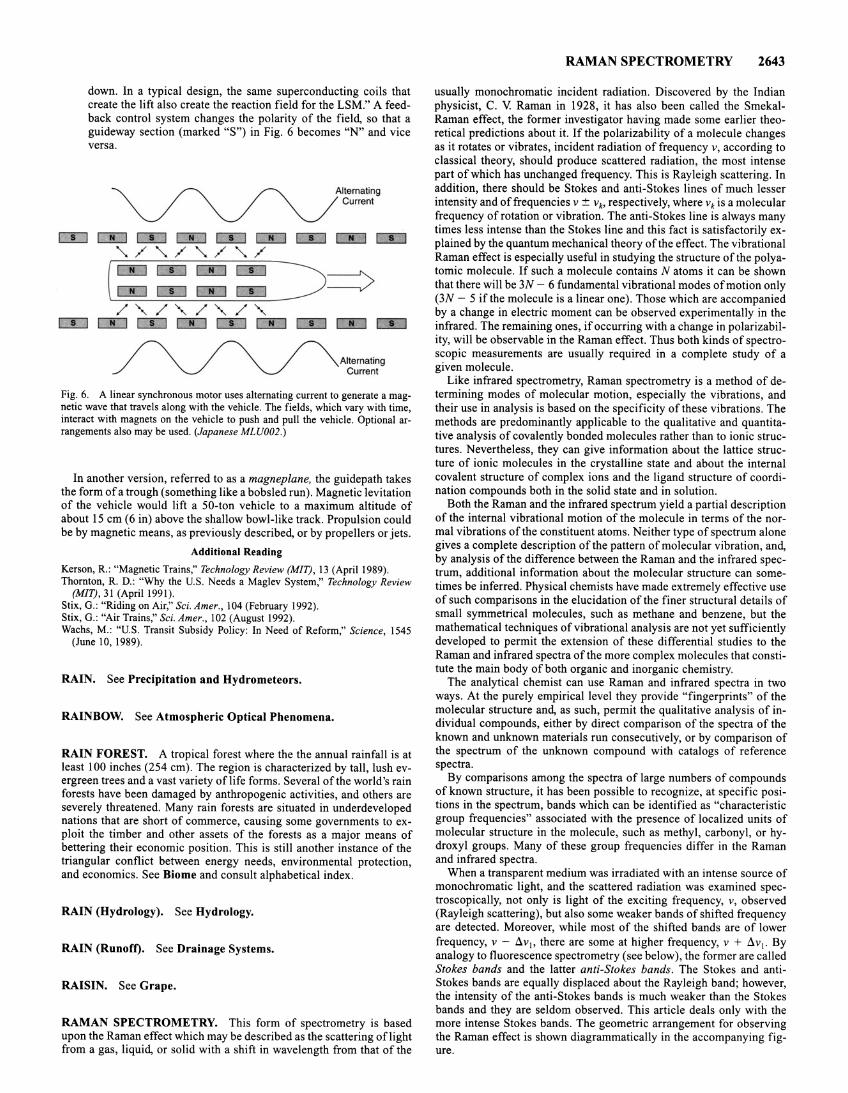
down. In a typical design, the same superconducting coils that create the lift also create the reaction field for the LSM." A feedback control system changes the polarity of the field, so that a guideway section (marked "S") in Fig. 6 becomes "N" and vice versa.
Alternating Current
CDo:::JCLlCIJCIJCIJCIJCIJCIJ './'./'./'./
Alternating Current
Fig. 6. A linear synchronous motor uses alternating current to generate a magnetic wave that travels along with the vehicle. The fields, which vary with time, interact with magnets on the vehicle to push and pull the vehicle. Optional arrangements also may be used. (Japanese MLU002.)
In another version, referred to as a magnep/ane, the guidepath takes the form of a trough (something like a bobsled run). Magnetic levitation of the vehicle would lift a 50-ton vehicle to a maximum altitude of about 15 em (6 in) above the shallow bowl-like track. Propulsion could be by magnetic means, as previously described, or by propellers or jets.
Additional Reading
Kerson, R. : "Magnetic Trains," Technology Review (MIT), 13 (April 1989). Thornton, R. D.: "Why the U.S. Needs a Maglev System," Technology Review
(MIT), 31 (Aprill991). Stix, G.: "Riding on Air," Sci. Amer., 104 (February 1992). Stix, G.: "Air Trains," Sci. Amer., 102 (August 1992). Wachs, M.: "U.S. Transit Subsidy Policy: In Need of Reform," Science, 1545
(June I 0, 1989).
RAIN. See Precipitation and Hydrometeors.
RAINBOW. See Atmospheric Optical Phenomena.
RAIN FOREST. A tropical forest where the the annual rainfall is at least 100 inches (254 em). The region is characterized by tall, lush evergreen trees and a vast variety oflife forms . Several of the world's rain forests have been damaged by anthropogenic activities, and others are severely threatened. Many rain forests are situated in underdeveloped nations that are short of commerce, causing some governments to exploit the timber and other assets of the forests as a major means of bettering their economic position. This is still another instance of the triangular conflict between energy needs, environmental protection, and economics. See Biome and consult alphabetical index.
RAIN (Hydrology). See Hydrology.
RAIN (Runoff). See Drainage Systems.
RAISIN. See Grape.
RAMAN SPECTROMETRY. This form of spectrometry is based upon the Raman effect which may be described as the scattering oflight from a gas, liquid, or solid with a shift in wavelength from that of the
RAMAN SPECTROMETRY 2643
usually monochromatic incident radiation. Discovered by the Indian physicist, C. V Raman in 1928, it has also been called the SmekalRaman effect, the former investigator having made some earlier theoretical predictions about it. If the polarizability of a molecule changes as it rotates or vibrates, incident radiation of frequency v, according to classical theory, should produce scattered radiation, the most intense part of which has unchanged frequency. This is Rayleigh scattering. In addition, there should be Stokes and anti-Stokes lines of much lesser intensity and of frequencies v ± vk> respectively, where vk is a molecular frequency of rotation or vibration. The anti-Stokes line is always many times less intense than the Stokes line and this fact is satisfactorily explained by the quantum mechanical theory of the effect. The vibrational Raman effect is especially useful in studying the structure of the polyatomic molecule. If such a molecule contains N atoms it can be shown that there will be 3N- 6 fundamental vibrational modes of motion only (3N- 5 if the molecule is a linear one). Those which are accompanied by a change in electric moment can be observed experimentally in the infrared. The remaining ones, if occurring with a change in polarizability, will be observable in the Raman effect. Thus both kinds of spectroscopic measurements are usually required in a complete study of a given molecule.
Like infrared spectrometry, Raman spectrometry is a method of determining modes of molecular motion, especially the vibrations, and their use in analysis is based on the specificity of these vibrations. The methods are predominantly applicable to the qualitative and quantitative analysis of covalently bonded molecules rather than to ionic structures. Nevertheless, they can give information about the lattice structure of ionic molecules in the crystalline state and about the internal covalent structure of complex ions and the ligand structure of coordination compounds both in the solid state and in solution.
Both the Raman and the infrared spectrum yield a partial description of the internal vibrational motion of the molecule in terms of the normal vibrations of the constituent atoms. Neither type of spectrum alone gives a complete description of the pattern of molecular vibration, and, by analysis of the difference between the Raman and the infrared spectrum, additional information about the molecular structure can sometimes be inferred. Physical chemists have made extremely effective use of such comparisons in the elucidation of the finer structural details of small symmetrical molecules, such as methane and benzene, but the mathematical techniques of vibrational analysis are not yet sufficiently developed to permit the extension of these differential studies to the Raman and infrared spectra of the more complex molecules that constitute the main body of both organic and inorganic chemistry.
The analytical chemist can use Raman and infrared spectra in two ways. At the purely empirical level they provide "fingerprints" of the molecular structure and, as such, permit the qualitative analysis of individual compounds, either by direct comparison of the spectra of the known and unknown materials run consecutively, or by comparison of the spectrum of the unknown compound with catalogs of reference spectra.
By comparisons among the spectra of large numbers of compounds of known structure, it has been possible to recognize, at specific positions in the spectrum, bands which can be identified as "characteristic group frequencies" associated with the presence of localized units of molecular structure in the molecule, such as methyl, carbonyl, or hydroxyl groups. Many of these group frequencies differ in the Raman and infrared spectra.
When a transparent medium was irradiated with an intense source of monochromatic light, and the scattered radiation was examined spectroscopically, not only is light of the exciting frequency, v, observed (Rayleigh scattering), but also some weaker bands of shifted frequency are detected. Moreover, while most of the shifted bands are of lower frequency, v- Llvl> there are some at higher frequency, v + Llv1• By analogy to fluorescence spectrometry (see below), the former are called Stokes bands and the latter anti-Stokes bands. The Stokes and antiStokes bands are equally displaced about the Rayleigh band; however, the intensity of the anti-Stokes bands is much weaker than the Stokes bands and they are seldom observed. This article deals only with the more intense Stokes bands. The geometric arrangement for observing the Raman effect is shown diagrammatically in the accompanying figure.
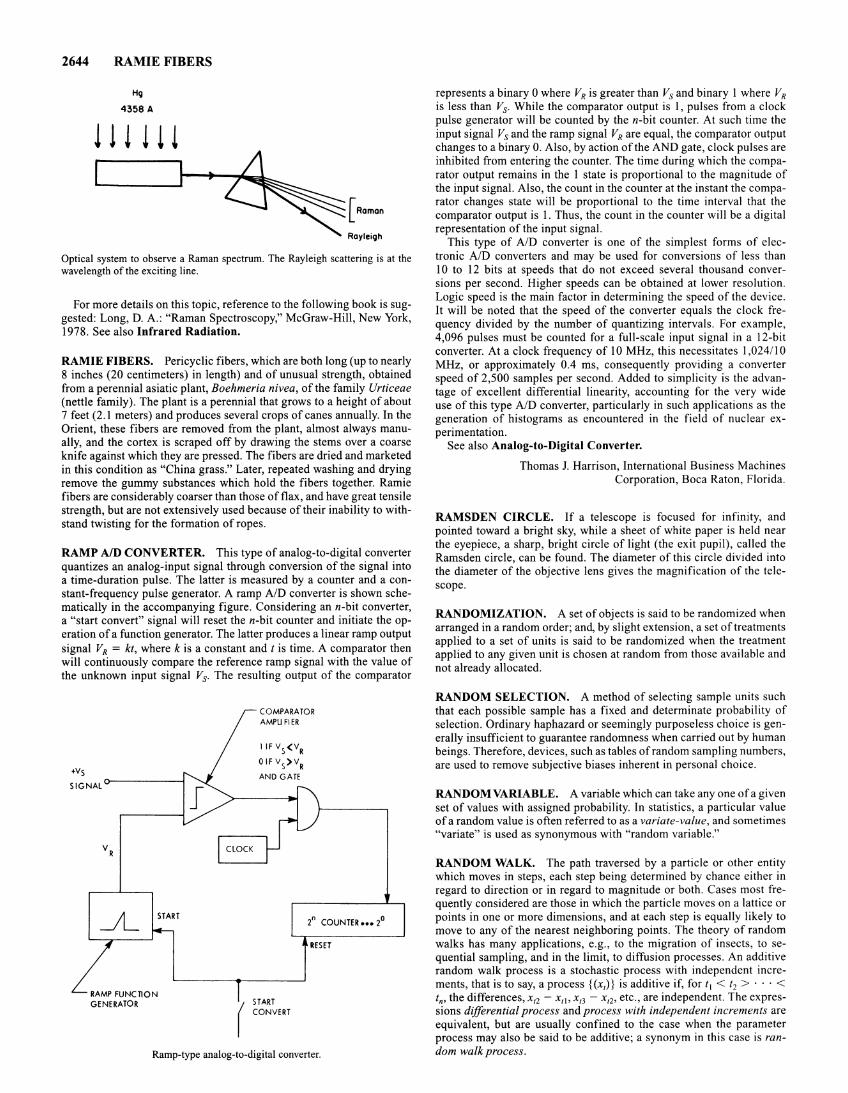
2644 RAMIE FIBERS
H<;~
4358 A
[Raman
Rayleigh
Optical system to observe a Raman spectrum. The Rayleigh scattering is at the wavelength of the exciting line.
For more details on this topic, reference to the following book is suggested: Long, D. A.: "Raman Spectroscopy," McGraw-Hill, New York, 1978. See also Infrared Radiation.
RAMIE FIBERS. Pericyclic fibers, which are both long (up to nearly 8 inches (20 centimeters) in length) and of unusual strength, obtained from a perennial asiatic plant, Boehmeria nivea, of the family Urticeae (nettle family). The plant is a perennial that grows to a height of about 7 feet (2.1 meters) and produces several crops of canes annually. In the Orient, these fibers are removed from the plant, almost always manually, and the cortex is scraped off by drawing the stems over a coarse knife against which they are pressed. The fibers are dried and marketed in this condition as "China grass." Later, repeated washing and drying remove the gummy substances which hold the fibers together. Ramie fibers are considerably coarser than those of flax, and have great tensile strength, but are not extensively used because of their inability to withstand twisting for the formation of ropes.
RAMP A/D CONVERTER. This type of analog-to-digital converter quantizes an analog-input signal through conversion of the signal into a time-duration pulse. The latter is measured by a counter and a constant-frequency pulse generator. A ramp AID converter is shown schematically in the accompanying figure. Considering an n-bit converter, a "start convert" signal will reset the n-bit counter and initiate the operation of a function generator. The latter produces a linear ramp output signal VR = kt, where k is a constant and t is time. A comparator then will continuously compare the reference ramp signal with the value of the unknown input signal Vs. The resulting output of the comparator
+Vs
SIGNAL
RAMP FUNCTION GENERATOR
COMPARATOR AMPU FIER
(
START CONVERT
2n COUNTER ••• 2°
RESET
Ramp-type analog-to-digital converter.
represents a binary 0 where VR is greater than Vs and binary 1 where VR is less than Vs. While the comparator output is 1, pulses from a clock pulse generator will be counted by the n-bit counter. At such time the input signal Vs and the ramp signal VR are equal, the comparator output changes to a binary 0. Also, by action of the AND gate, clock pulses are inhibited from entering the counter. The time during which the comparator output remains in the 1 state is proportional to the magnitude of the input signal. Also, the count in the counter at the instant the comparator changes state will be proportional to the time interval that the comparator output is I. Thus, the count in the counter will be a digital representation of the input signal.
This type of AID converter is one of the simplest forms of electronic AID converters and may be used for conversions of less than 10 to 12 bits at speeds that do not exceed several thousand conversions per second. Higher speeds can be obtained at lower resolution. Logic speed is the main factor in determining the speed of the device. It will be noted that the speed of the converter equals the clock frequency divided by the number of quantizing intervals. For example, 4,096 pulses must be counted for a full-scale input signal in a 12-bit converter. At a clock frequency of 10 MHz, this necessitates 1 ,024/10 MHz, or approximately 0.4 ms, consequently providing a converter speed of 2,500 samples per second. Added to simplicity is the advantage of excellent differential linearity, accounting for the very wide use of this type AID converter, particularly in such applications as the generation of histograms as encountered in the field of nuclear experimentation.
See also Analog-to-Digital Converter.
Thomas J. Harrison, International Business Machines Corporation, Boca Raton, Florida.
RAMSDEN CIRCLE. If a telescope is focused for infinity, and pointed toward a bright sky, while a sheet of white paper is held near the eyepiece, a sharp, bright circle of light (the exit pupil), called the Ramsden circle, can be found. The diameter of this circle divided into the diameter of the objective lens gives the magnification of the telescope.
RANDOMIZATION. A set of objects is said to be randomized when arranged in a random order; and, by slight extension, a set of treatments applied to a set of units is said to be randomized when the treatment applied to any given unit is chosen at random from those available and not already allocated.
RANDOM SELECTION. A method of selecting sample units such that each possible sample has a fixed and determinate probability of selection. Ordinary haphazard or seemingly purposeless choice is generally insufficient to guarantee randomness when carried out by human beings. Therefore, devices, such as tables of random sampling numbers, are used to remove subjective biases inherent in personal choice.
RANDOM VARIABLE. A variable which can take any one of a given set of values with assigned probability. In statistics, a particular value of a random value is often referred to as a variate-value, and sometimes "variate" is used as synonymous with "random variable."
RANDOM WALK. The path traversed by a particle or other entity which moves in steps, each step being determined by chance either in regard to direction or in regard to magnitude or both. Cases most frequently considered are those in which the particle moves on a lattice or points in one or more dimensions, and at each step is equally likely to move to any of the nearest neighboring points. The theory of random walks has many applications, e.g., to the migration of insects, to sequential sampling, and in the limit, to diffusion processes. An additive random walk process is a stochastic process with independent increments, that is to say, a process { (x1)} is additive if, for t 1 < t2 > · · · < t., the differences, x12 - x11 , x13 - x 12 , etc., are independent. The expressions differential process and process with independent increments are equivalent, but are usually confined to the case when the parameter process may also be said to be additive; a synonym in this case is random walk process.
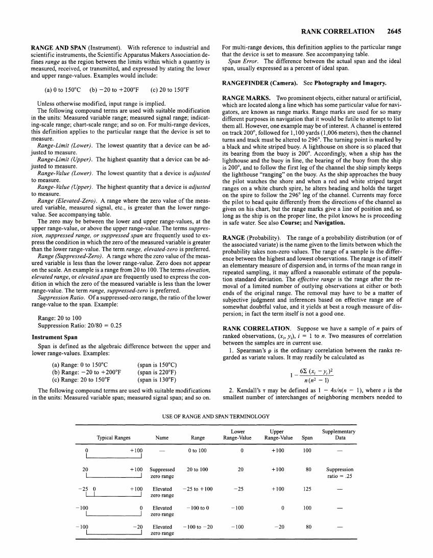
RANGE AND SPAN (Instrument). With reference to industrial and scientific instruments, the Scientific Apparatus Makers Association defines range as the region between the limits within which a quantity is measured, received, or transmitted, and expressed by stating the lower and upper range-values. Examples would include:
(a) 0 to 150°C (b) -20 to +200°F (c) 20 to 150°F
Unless otherwise modified, input range is implied. The following compound terms are used with suitable modification
in the units: Measured variable range; measured signal range; indicating-scale range; chart-scale range; and so on. For multi-range devices, this definition applies to the particular range that the device is set to measure.
Range-Limit (Lower). The lowest quantity that a device can be adjusted to measure.
Range-Limit (Upper). The highest quantity that a device can be adjusted to measure.
Range- Value (Lower). The lowest quantity that a device is adjusted to measure.
Range-Value (Upper). The highest quantity that a device is adjusted to measure.
Range (Elevated-Zero). A range where the zero value of the measured variable, measured signal, etc., is greater than the lower rangevalue. See accompanying table.
The zero may be between the lower and upper range-values, at the upper range-value, or above the upper range-value. The terms suppression, suppressed range, or suppressed span are frequently used to express the condition in which the zero of the measured variable is greater than the lower range-value. The term range, elevated-zero is preferred.
Range (Suppressed-Zero). A range where the zero value of the measured variable is less than the lower range-value. Zero does not appear on the scale. An example is a range from 20 to 100. The terms elevation, elevated range, or elevated span are frequently used to express the condition in which the zero of the measured variable is less than the lower range-value. The term range, suppressed-zero is preferred.
Suppression Ratio. Of a suppressed-zero range, the ratio of the lower range-value to the span. Example:
Range: 20 to 100 Suppression Ratio: 20/80 = 0.25
Instrument Span
Span is defined as the algebraic difference between the upper and lower range-values. Examples:
(a) Range: 0 to 150°C (b) Range: -20 to + 200°F (c) Range: 20 to 150°F
(span is 150°C) (span is 220°F) (span is 130°F)
The following compound terms are used with suitable modifications in the units: Measured variable span; measured signal span; and so on.
RANK CORRELATION 2645
For multi-range devices, this definition applies to the particular range that the device is set to measure. See accompanying table.
Span Error. The difference between the actual span and the ideal span, usually expressed as a percent of ideal span.
RANGEFINDER (Camera). See Photography and Imagery.
RANGE MARKS. Two prominent objects, either natural or artificial, which are located along a line which has some particular value for navigators, are known as range marks. Range marks are used for so many different purposes in navigation that it would be futile to attempt to list them all. However, one example may be of interest. A channel is entered on track 200°, followed for 1,100 yards ( 1,006 meters), then the channel turns and track must be altered to 296°. The turning point is marked by a black and white striped buoy. A lighthouse on shore is so placed that its bearing from the buoy is 200°. Accordingly, when a ship has the lighthouse and the buoy in line, the bearing of the buoy from the ship is 200°, and to follow the first leg of the channel the ship simply keeps the lighthouse "ranging" on the buoy. As the ship approaches the buoy the pilot watches the shore and when a red and white striped target ranges on a white church spire, he alters heading and holds the target on the spire to follow the 296° leg of the channel. Currents may force the pilot to head quite differently from the directions of the channel as given on his chart, but the range marks give a line of position and, so long as the ship is on the proper line, the pilot knows he is proceeding in safe water. See also Course; and Navigation.
RANGE (Probability). The range of a probability distribution (or of the associated variate) is the name given to the limits between which the probability takes non-zero values. The range of a sample is the difference between the highest and lowest observations. The range is of itself an elementary measure of dispersion and, in terms of the mean range in repeated sampling, it may afford a reasonable estimate of the population standard deviation. The effective range is the range after the removal of a limited number of outlying observations at either or both ends of the original range. The removal may have to be a matter of subjective judgment and inferences based on effective range are of somewhat doubtful value, and it yields at best a rough measure of dispersion; in fact the term itself is not a good one.
RANK CORRELATION. Suppose we have a sample of n pairs of ranked observations, (xi, Yi), i = 1 to n. Two measures of correlation between the samples are in current use.
1. Spearman's p is the ordinary correlation between the ranks regarded as variate values. It may readily be calculated as
1 _ 6~ (X;- y,)2 n (n 2 - 1)
2. Kendall's T may be defined as 1 - 4s/n(n - 1 ), where s is the smallest number of interchanges of neighboring members needed to
USE OF RANGE AND SPAN TERMINOLOGY
Lower Upper Supplementary Typical Ranges Name Range Range-Value Range-Value Span Data
0 +100 0 to 100 0 +100 100
20 +100 Suppressed 20 to 100 20 +100 80 Suppression zero range ratio= .25
-25 0 +100 Elevated -25 to + 100 -25 +100 125 zero range
-100 0 Elevated -100to0 -100 0 100 zero range
-100 -20 Elevated -100 to -20 -100 -20 80 zero range
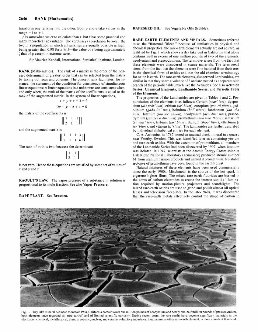
2646 RANK (Mathematics)
transform one ranking into the other. Both p and T take values in the range -1 to + 1.
p is somewhat easier to calculate than T, butT has some practical and many theoretical advantages. The (ordinary) correlation between the two in a population in which all rankings are equally possible is high, being greater than 0.98 for n 2:: 5-the value ofT being approximately i that of p except in extreme cases.
Sir Maurice Kendall, International Statistical Institute, London.
RANK (Mathematics). The rank of a matrix is the order of the nonzero determinant of greatest order that can be selected from the matrix by taking out rows and columns. The concept rank facilitates, for instance, the statement of the condition for consistency of simultaneous linear equations: m linear equations inn unknowns are consistent when, and only when, the rank of the matrix of the coefficients is equal to the rank of the augmented matrix. In the system of linear equations,
x+y+z+3=0
2x+y+z+4=0
the matrix of the coefficients is
II~ : II and the augmented matrix is
II~ ~ ~ II The rank of both is two, because the determinant
is not zero. Hence these equations are satisfied by some set of values of x andy and z.
RAOULT'S LAW. The vapor pressure of a substance in solution is proportional to its mole fraction. See also Vapor Pressure.
RAPE PLANT. See Brassica.
RAPESEED OIL. See Vegetable Oils (Edible).
RARE-EARTH ELEMENTS AND METALS. Sometimes referred to as the "fraternal fifteen," because of similarities in physical and chemical properties, the rare-earth elements actually are not so rare, as testified by Fig. I which shows a dry lake bed in California that alone contains well in excess of one million pounds of two of the elements, neodymium and praseodymium. The term rare arises from the fact that these elements were discovered in scarce materials. The term earth stems from the fact that the elements were first isolated from their ores in the chemical form of oxides and that the old chemical terminology for oxide is earth. The rare-earth elements, also termed Lanthanides, are similar in that they share a valence of3 and are treated as a separate side branch of the periodic table, much like the Actinides. See also Actinide Series; Chemical Elements; Lanthanide Series; and Periodic Table of the Elements.
The properties of the Lanthanides are given in Tables I and 2. Pronunciation of the elements is as follows: Cerium (sear' ium ), dysprosium (dis proz' ium), erbium (ur' bium), europium (yoo ro pium), gadolinium (gada lin ' ium), holmium (hot' mium), lanthanum (Ian ' tha num ), lutetium (Zoo tee' shium ), neodymium (neo dim' ium ), praseodymium (pra zee o dim' ium ), promethium (pro mee' thium ), samarium (sa mar' ium ), terbium (tur ' bium ), thulium (thuo' lium ), ytterbium (i tur 'bium), and yttrium (it' rium). The lanthanides are further described by individual alphabetical entries for each element.
C. A. Arrhenius, in 1787, noted an unusual black mineral in a quarry near Ytterby, Sweden. This was identified later as containing yttrium and rare-earth oxides. With the exception of promethium, all members of the Lanthanide Series had been discovered by 1907, when lutetium was isolated. In 194 7, scientists at the Atomic Energy Commission at Oak Ridge National Laboratory (Tennessee) produced atomic number 61 from uranium fission products and named it promethium. No stable isotopes of promethium have been found in the earth's crust.
Natural mixtures of these elements have been used commercially since the early 1900s. Mischmetal is the source of the hot spark in cigarette lighter flints. The mixed rare-earth fluorides are burned in the cores of carbon electrodes to create the intense sunlike illumination required by motion-picture projectors and searchlights. The mixed rare-earth oxides are used to grind and polish almost all optical lenses and television faceplates. In the late-1940s, it was discovered that the rare-earth metals effectively control the shape of carbon in
Fig. I. Dry lake mineral bed near Mountain Pass, California contains over one million pounds of neodymium and nearly one-half million pounds of praseodymium, both elements once regarded as "rare earths" and of limited scientific curiosity. During recent years, the rare earths have become significant materials in the electronic, chemical, metallurgical, glass, cryogenic, nuclear, and ceramic refractory industries. Lanthanum, another rare-earth element, is more abundant than lead.
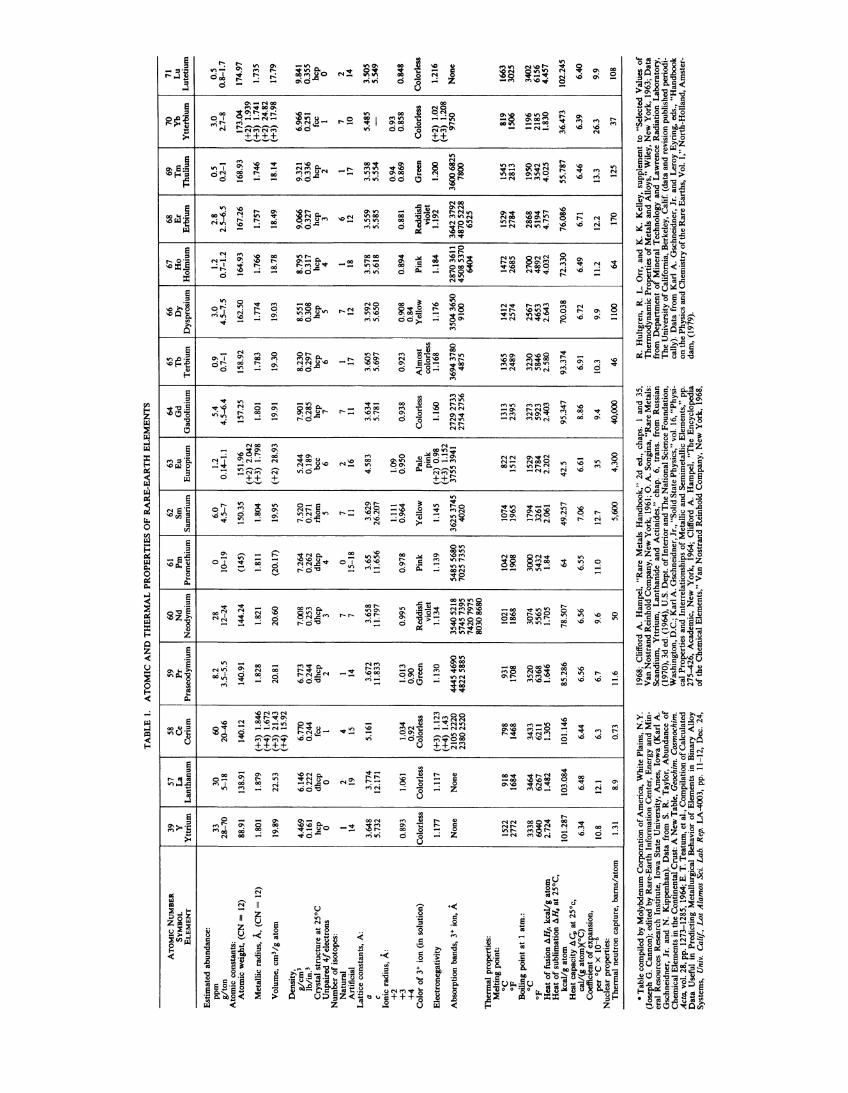
TA
BL
E I
. A
TO
MIC
AN
D T
HE
RM
AL
PR
OP
ER
TIE
S O
F R
AR
E-E
AR
TH
EL
EM
EN
TS
ATO
MIC
NU
MB
ER
39
57
58
SYM
BOL
y L
a C
e EL
EMEN
T Y
ttri
um
Lan
than
um
Cer
ium
Est
imat
ed a
bund
ance
: pp
m
33
30
60
glt
on
28
-70
5-18
20
-46
Ato
mic
con
stan
ts:
Ato
mic
wei
ght,
(CN
= 1
2)
88.9
1 13
8.91
14
0.12
Met
alli
c ra
dius
, A,
(C
N =
12)
1.
801
1.87
9 (+
3)
1.84
6 (+
4)
1.67
2 V
olum
e, c
m3 /
g a
tom
19
.89
22.5
3 (+
3) 2
1.43
(+
4)
15.9
2 D
ensi
ty,
glc
m'
4.46
9 6.
146
6.77
0 lb
/in
.'
0.16
1 0.
222
0.24
4 C
ryst
al s
truc
ture
at
25°C
hc
p dh
cp
fcc
Unp
aire
d 4
/ ele
ctro
ns
0 0
I N
umbe
r o
f is
otop
es:
Nat
ural
I
2 4
Art
ific
ial
14
19
15
Lat
tice
con
stan
ts,
A:
a 3.
648
3.77
4 5.
161
c Io
nic
rad
ius,
A:
5.73
2 12
.171
+2
+
3
0.89
3 1.
061
1.03
4 +
4
0.92
C
olor
of
]+ i
on (
in s
olut
ion)
C
olor
less
C
olor
less
C
olor
less
Ele
ctro
nega
tivi
ty
1.17
7 1.
117
(+3)
1.1
23
Abs
orpt
ion
band
s, 3
+ io
n, A
(+
4) 1
.43
Non
e N
one
2105
222
0 23
80 2
520
The
rmal
pro
pert
ies:
M
elti
ng p
oint
: o
c
1522
91
8 79
8 oF
27
72
1684
14
68
Boi
ling
poi
nt a
t I
atm
.: o
c
3338
34
64
3433
o
F
6040
62
67
6211
H
eat
of
fusi
on b
.H,.
kcaV
g at
om
Hea
t o
f su
blim
atio
n b.
H,
at 2
5°C
, 2.
724
1.48
2 1.
305
kcaV
g at
om
101.
287
103.
084
101.
146
Hea
t ca
paci
ty b
.c;,
at 2
5°c,
ca
l/(g
ato
m)(
OC
) 6.
34
6.48
6.
44
Coe
ffic
ient
of e
xgan
sion
, pe
r °C
X 1
0-10
.8
12.1
6.
3 N
ucle
ar p
rope
rtie
s:
Th
erm
al n
eutr
on c
aptu
re,
bar
ns/
atom
1.
31
8.9
0.73
• T
able
com
pile
d by
Mol
ybde
num
Cor
pora
tion
of A
mer
ica,
Whi
te P
lain
s, N
.Y.
(Jos
eph
G.
Can
non)
; ed
ited
by
Rar
e-E
arth
Inf
orm
atio
n C
ente
r, E
nerg
y an
d M
in
eral
Res
ourc
es R
esea
rch
Inst
itut
e, I
owa
Sta
te U
nive
rsit
y, A
mes
, Io
wa
(Kar
l A
. G
schn
eidn
er,
Jr.
and
N.
Kip
penh
an).
D
ata
from
S.
R.
Tay
lor,
Abu
ndan
ce o
f C
hem
ical
Ele
men
ts in
the
Con
tine
ntal
Cru
st:
A N
ew T
able
, G
each
im.
Cos
mac
him
. A
cta,
vol
. 28
, pp
. 12
73-1
285,
196
4; E
. T
. T
eatu
m, e
t al.,
Com
pila
tion
of C
alcu
late
d D
ata
Use
ful
in P
redi
ctin
g M
etal
lurg
ical
Beh
avio
r o
f E
lem
ents
in
Bin
ary
All
oy
Sys
tem
s,
Uni
v.
Cal
if,
Los
Ala
mos
Sci
. La
b.
Rep
. L
A-4
003,
pp.
11
-12,
Dec
. 24
,
59
60
61
62
63
64
Pr
Nd
P
m
Sm
Eu
G
d
Pra
seod
ymiu
m
Neo
dym
ium
P
rom
ethi
um
Sam
ariu
m
Eur
opiu
m
Gad
olin
ium
8.2
28
0 6.
0 1.
2 5.
4 3.
5-5.
5 12
-24
1(}.
..19
4.5-
7 0.
14-1
.1
4.5-
6.4
140.
91
144.
24
(145
) 15
0.35
15
1.96
15
7.25
(+
2)
2.04
2 1.
828
1.82
1 1.
811
1.80
4 (+
3)
1.79
8 1.
801
20.8
1 20
.60
(20.
17)
19.9
5 (+
2)
28.9
3 19
.91
6.77
3 7.
008
7.26
4 7.
520
5.24
4 7.
901
0.24
4 0.
253
0.26
2 0.
271
0.18
9 0.
285
dhcp
dh
cp
dhcp
rh
om
bee
hcp
2 3
4 5
6 7
I 7
0 7
2 7
14
7 15
-18
II
16
11
3.67
2 3.
658
3.65
3.
629
4.58
3 3.
634
11.8
33
11.7
97
11.6
56
26.2
07
5.78
1
1.11
1 1.
09
1.01
3 0.
995
0.97
8 0.
964
0.95
0 0.
938
0.90
G
reen
R
eddi
sh
Pin
k Y
ello
w
Pal
e C
olor
less
vi
olet
pi
nk
1.13
0 1.
134
1.13
9 1.
145
(+2)
0.9
8 1.
160
(+3)
1.
152
4445
469
0 35
40 5
218
5485
568
0 36
25 3
745
3755
394
1 27
29 2
733
4822
588
5 57
45 7
395
7025
735
5 40
20
2754
275
6 74
2079
75
8030
8680
931
1021
10
42
1074
82
2 13
13
1708
18
68
1908
19
65
1512
23
95
3520
30
74
3000
17
94
1529
32
73
6368
55
65
5432
32
61
2784
59
23
1.64
6 1.
705
1.84
2.
061
2.20
2 2.
403
85.2
86
78.5
07
64
49.2
57
42.5
95
.347
6.56
6.
56
6.55
7.
06
6.61
8.
86
6.7
9.6
11.0
12
.7
35
9.4
11.6
so
5,
600
4,30
0 40
,000
1968
; C
liff
ord
A.
Ham
pel,
"R
are
Met
als
Han
dboo
k,"
2d e
d.,
chap
s.
I an
d 35
, V
an N
ostr
and
Rei
nhol
d C
ompa
ny,
New
Yor
k, 1
961;
0.
A.
Son
gina
, "R
are
Met
als:
S
cand
ium
, Y
ttri
um,
Lan
than
ide
and
Act
inid
es,"
cha
p.
6,
tran
s.
from
R
ussi
an
(197
0),
3d e
d. (
1964
), U
.S.
Dep
t. o
fln
teri
or
and
The
Nat
iona
l Sci
ence
Fou
ndat
ion,
W
ashi
ngto
n, D
.C.;
Kar
l A
. G
schn
eidn
er, J
r.,
"Sol
id S
tate
Phy
sics
," v
ol.
16, "
Phy
si
cal
Pro
pert
ies
and
Inte
rrel
atio
nshi
ps o
f M
etal
lic
and
Sem
imet
alli
c E
lem
ents
," p
p.
275-
426,
Aca
dem
ic,
New
Yor
k, 1
964;
Cli
ffor
d A
. H
ampe
l, '
'The
Enc
yclo
pedi
a o
f th
e C
hem
ical
Ele
men
ts,"
Van
Nos
tran
d R
einh
old
Com
pany
, N
ew Y
ork,
196
8,
65
66
67
68
69
70
71
1b
D
y H
o
Er
Tm
Y
b L
u T
erbi
um
Dys
pro
siu
m
Hol
miu
m
Erb
ium
T
huli
um
Ytt
erbi
um
Lu
teti
um
0.9
3.0
1.2
2.8
0.5
3.0
0.5
0.7-
1 4.
5-7.
5 0.
7-1.
2 2.
5-6.
5 0.
2-1
2.7-
8 0.
8-1.
7
158.
92
162.
50
164.
93
167.
26
168.
93
173.
04
174.
97
(+2
) 1.
939
1.78
3 1.
774
1.76
6 1.
757
1.74
6 (+
3)
1.74
1 1.
735
19.3
0 19
.03
18.7
8 18
.49
(+2)
24.
82
18.1
4 (+
3)
17.9
8 17
.79
8.23
0 8.
551
8.79
5 9.
066
9.32
1 6.
966
9.84
1 0.
297
0.30
8 0.
317
0.32
7 0.
336
0.25
1 0.
355
hcp
hcp
hcp
hcp
hcp
fcc
hcp
6 5
4 3
2 I
0
I 7
I 6
I 7
2 17
12
18
12
17
10
14
3.60
5 3.
592
3.57
8 3.
559
3.53
8 5.
485
3.50
5 5.
697
5.65
0 5.
618
5.58
5 5.
554
-5.
549
0.94
0.
93
0.92
3 0.
908
0.89
4 0.
881
0.86
9 0.
858
0.84
8 0.
84
Alm
ost
Yel
low
P
ink
Red
dish
G
reen
C
olor
less
C
olor
less
co
lorl
ess
viol
et
1.16
8 1.
176
1.18
4 1.
192
1.20
0 (+
2)
1.02
1.
216
3694
3780
35
04 3
650
2870
3611
36
42 3
792
(+3
) 1.
208
3600
6825
97
50
Non
e 48
75
9100
45
08 5
370
4870
522
8 78
00
6404
65
25
1365
14
12
1472
15
29
1545
81
9 16
63
2489
25
74
2685
27
84
2813
15
06
3025
3230
25
67
2700
28
68
1950
11
96
3402
58
46
4653
48
92
5194
35
42
2185
61
56
2.58
0 2.
643
4.03
2 4.
757
4.02
5 1.
830
4.45
7
93.3
74
70.0
38
72.3
30
76.0
86
55.7
87
36.4
73
102.
245
6.91
6.
72
6.49
6.
71
6.46
6.
39
6.40
10.3
9.
9 11
.2
12.2
13
.3
26.3
9.
9
46
1100
64
17
0 12
5 37
10
8
R.
Hul
tgre
n, R
. L
. O
rr,
and
K.
K.
Kel
ley,
sup
plem
ent
to "
Sel
ecte
d V
alue
s o
f T
herm
odyn
amic
Pro
pert
ies
of
Met
als
and
All
oys,
" W
iley
, N
ew Y
ork,
196
3; D
ata
from
Dep
artm
ent
of
Min
eral
Tec
hnol
ogy
and
Law
renc
e R
adia
tion
Lab
orat
ory,
T
he U
nive
rsit
y o
f Cal
ifor
nia,
Ber
kele
y, C
alif
. (d
ata
and
revi
sion
pub
lish
ed p
erio
di
call
y).
Dat
a fr
om K
arl
A.
Gsc
hnei
dner
, Jr
. an
d L
eroy
Eyr
ing,
eds
., "H
andb
ook
on th
e P
hysi
cs a
nd C
hem
istr
y o
f the
Rar
e E
arth
s, V
ol.
1,"
Nor
th-H
olla
nd, A
mst
er
dam
, (1
979)
.
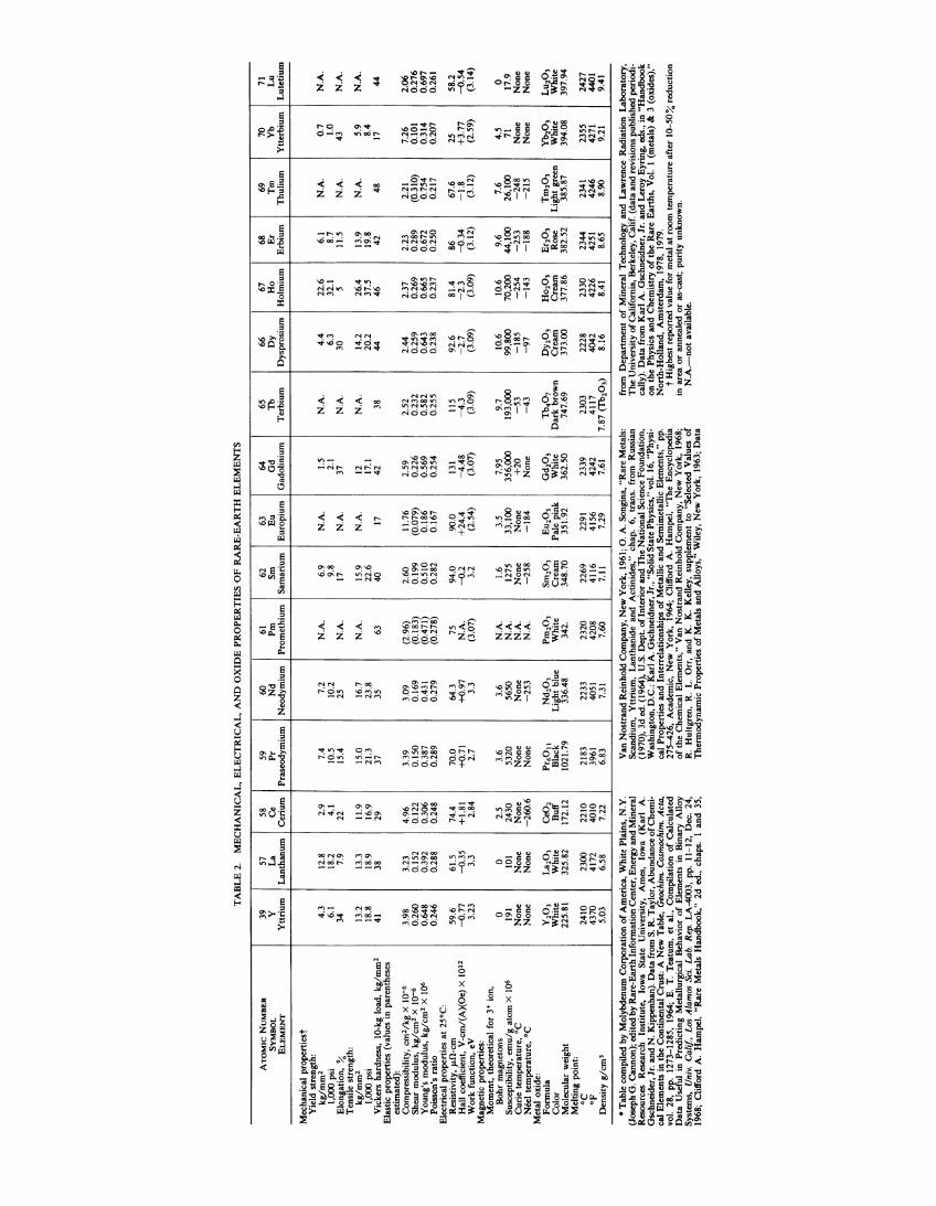
TA
BL
E 2
. M
EC
HA
NIC
AL
, E
LE
CT
RIC
AL
, A
ND
OX
IDE
PR
OP
ER
TIE
S O
F R
AR
E-E
AR
TH
EL
EM
EN
TS
ATO
MIC
NU
MB
ER
39
57
58
SYM
BO
L y
La
Ce
EL
EM
EN
T
Ytt
rium
L
anth
anum
C
eriu
m
Mec
hani
cal
prop
erti
est
Yie
ld s
tren
gth:
k
glm
m2
4.3
12.8
2.
9 1,
000
psi
6.1
18.2
4.
1 E
lon
gati
on,
%
34
7.9
22
Ten
sile
str
engt
h:
kg/m
m>
13
.2
13.3
11
.9
1,00
0 ps
i 18
.8
18.9
16
.9
Vic
kers
har
dnes
s, 1
0-kg
loa
d, k
g/m
m>
41
38
29
E
last
ic p
rope
rtie
s (v
alue
s in
par
enth
eses
es
tim
ated
):
Com
pres
sibi
lity
, cm
2 /k
g X
10
-6
3.98
3.
23
4.96
S
hear
mod
ulus
, kg
/em
> X
1
0-•
0.
260
0.1
52
0.
122
You
ng's
mod
ulus
, k
glc
m2
X
106
0.64
8 0.
392
0.30
6 P
oiss
on's
rat
io
0.24
6 0.
288
0.24
8 E
lect
rica
l pr
oper
ties
at
25°C
: R
esis
tivi
ty,
J.L
!l·cm
59
.6
61.5
74
.4
Hal
l co
effi
cien
t, V
-cm
/(A
)(O
e) X
10
12
--o.
77
--o.
35
+1.
81
Wor
k fu
ncti
on,
eV
3.23
3.
3 2.
84
Mag
neti
c pr
oper
ties
: M
omen
t, t
heor
etic
al f
or 3
+ i
on,
Boh
r m
agne
tons
0
0 2.
5 S
usce
ptib
ilit
y, e
mu
/g a
tom
X
106
191
101
2430
C
uri
e te
mp
erat
ure
, oc
N
one
Non
e N
one
NcX
I te
mpe
ratu
re,
oc
Non
e N
one
-26
0.6
M
etal
oxi
de:
Fo
rmu
la
Y,o
, L
a,o
, C
eO,
Col
or
Whi
te
Whi
te
Buf
f M
olec
ular
wei
ght
225.
81
325.
82
172.
12
Mel
ting
poi
nt:
oc
2410
23
00
2210
o
F
4370
41
72
4010
D
ensi
ty g
lcm
' 5.
03
6.58
7.
22
~---
• T
able
com
pile
d by
Mol
ybde
num
Cor
pora
tion
of
Am
eric
a, W
hite
Pla
ins,
N.Y
. (J
osep
h G
. Can
non)
; edi
ted
by R
are-
Ear
th I
nfor
mat
ion
Cen
ter,
Ene
rgy
and
Min
eral
R
esou
rces
R
esea
rch
Inst
itut
e,
Iow
a S
tate
U
nive
rsit
y,
Am
es,
Iow
a (K
arl
A.
Gsc
hnei
der,
Jr.
an
d N
. K
ippe
nhan
). D
ata
from
S.
R. T
aylo
r, A
bund
ance
of C
hem
ica
l E
lem
ents
in
the
Con
tine
ntal
Cru
st:
A N
ew T
able
, G
eoch
im.
Cos
moc
him
. A
cta.
vo
l. 28
, pp
. 12
73-1
285,
196
4; E
. T
. T
eatu
m,
et a
!.,
Com
pila
tion
of
Cal
cula
ted
Dat
a U
sefu
l in
Pre
dict
ing
Met
allu
rgic
al B
ehav
ior
of
Ele
men
ts i
n B
inar
y A
lloy
S
yste
ms,
U
niv.
C
alif.
, Lo
s A
lam
os S
ci.
Lab.
R
ep.
LA
-400
3, p
p.
11-1
2, D
ec.
24,
1968
; C
liff
ord
A.
Ham
pel,
"R
are
Met
als
Han
dboo
k,"
2d e
d.,
chap
s.
I an
d 3
5,
59
60
61
62
63
64
65
66
67
68
69
70
71
Pr
Nd
P
m
Sm
E
u
Gd
T
h
Dy
H
o
Er
Tm
Y
b
Lu
P
rase
odym
ium
N
eody
miu
m
Pro
met
hiu
m
Sam
ariu
m
Eu
rop
ium
G
adol
iniu
m
Ter
biu
m
Dys
pro
siu
m
Hol
miu
m
Erb
ium
T
huli
um
Ytt
erbi
um
Lu
teti
um
7.4
7.2
N.A
. 6.
9 N
.A.
1.5
N.A
. 4.
4 22
.6
6.1
N.A
. 0.
7 N
.A.
10.5
10
.2
9.8
2.1
6.3
32.1
8.
7 1.
0 15
.4
25
N.A
. 17
N
.A.
37
N.A
. 30
5
11.5
N
.A.
43
N.A
.
15.0
16
.7
N.A
. 15
.9
N.A
. 12
N
.A.
14.2
26
.4
13.9
N
.A.
5.9
N.A
. 21
.3
23.8
22
.6
17.1
20
.2
37.5
19
.8
8.4
37
35
63
40
17
42
38
44
46
42
48
17
44
3.39
3.
09
(2.9
6)
2.60
11
.76
2.59
2.
52
2.44
2.
37
2.23
2.
21
7.26
2.
06
0.15
0 0.
169
(0.1
83)
0.19
9 (0
.079
) 0.
226
0.23
2 0.
259
0.26
9 0.
289
(0.3
10)
0.10
1 0.
276
0.38
7 0.
431
(0.4
71)
0.51
0 0.
186
0.56
9 0.
582
0.64
3 0.
665
0.67
2 0.
754
0.31
4 0.
697
0.28
9 0.
279
(0.2
78)
0.28
2 0.
167
0.25
4 0.
255
0.23
8 0.
237
0.25
0 0.
217
0.20
7 0.
261
70.0
64
.3
75
94.0
90
.0
131
115
92.6
81
.4
86
67.6
25
58
.2
+0.
71
+0.
97
N.A
. --
o.2
+2
4.4
-4
.48
-4
.3
-2.7
-2
.3
--o.
34
-1.8
+
3.7
7
--o.
54
2.7
3.3
(3.0
7)
3.2
(2.5
4)
(3.0
7)
(3.0
9)
(3.0
9)
(3.0
9)
(3.1
2)
(3.1
2)
(2.5
9)
(3.1
4)
3.6
3.6
N.A
. 1.
6 3.
5 7.
95
9.7
10.6
10
.6
9.6
7.6
4.5
0 53
20
5650
N
.A.
1275
33
,100
35
6,00
0 19
3,00
0 99
,800
70
,200
44
,100
26
,100
71
17
.9
Non
e N
one
N.A
. N
one
Non
e +
20
-5
3
-18
5
-25
4
-25
3
-24
8
Non
e N
on
e N
one
-25
3
N.A
. -2
58
-1
84
N
one
-43
-9
7
-14
3
-18
8
-21
5
Non
e N
one
Pr 6
011
N
d,o
, P
m20
3 S
m20
3 E
u,o
, G
d20
3 T
h.o
7 D
y20
3 H
o20
3 E
r 20
3 T
m20
3 Y
b20
3 L
u 20
3
Bla
ck
Lig
ht b
lue
Whi
te
Cre
am
Pal
e pi
nk
Whi
te
Dar
k b
row
n C
ream
C
ream
R
ose
Lig
ht g
reen
W
hite
W
hite
10
21.7
9 33
6.48
34
2.
348.
70
351.
92
362.
50
747.
69
373.
00
377.
86
382.
52
385.
87
394.
08
397.
94
2183
22
33
2320
22
69
2291
23
39
2303
22
28
2330
23
44
2341
23
55
2427
39
61
4051
42
08
4116
41
56
4242
41
17
4042
42
26
4251
42
46
4271
44
01
6.83
7.
31
7.60
7.
11
7.29
7.
61
7.87
(T
h20
3)
8.16
8.
41
8.65
8.
90
9.21
9.
41
Van
Nos
tran
d R
einh
old
Com
pany
, N
ew Y
ork,
196
1; 0
. A
. S
ongi
na, "
Rar
e M
etal
s:
Sca
ndiu
m,
Ytt
rium
, L
anth
anid
e an
d A
ctin
ides
," c
hap.
6,
tr
ans.
fr
om
Rus
sian
(1
970)
, 3d
ed.
(19
64),
U.S
. D
ept.
ofl
nte
rio
r an
d T
he
Nat
iona
l Sc
ienc
e F
ound
atio
n,
Was
hing
ton,
D.C
.: K
arl A
. Gsc
hnei
dner
, Jr.
, "S
olid
Sta
te P
hysi
cs,"
vol
. 16
, "P
hysi
ca
l P
rope
rtie
s an
d I
nter
rela
tion
ship
s o
f M
etal
lic
and
Scm
imet
alli
c E
lem
ents
," p
p.
275-
426,
Aca
dem
ic,
New
Yor
k, 1
964;
Cli
ffor
d A
. H
ampe
l, "
Th
e E
ncyc
lope
dia
of
the
Che
mic
al E
lem
ents
," V
an N
ostr
and
Rei
nhol
d C
ompa
ny,
New
Yor
k, 1
968;
R
. H
ultg
ren,
R.
L.
Orr
, an
d K
. K
. K
elle
y, s
uppl
emen
t to
"S
elec
ted
Val
ues
of
The
rmod
ynam
ic P
rope
rtie
s o
f M
etal
s an
d A
lloy
s,"
Wil
ey,
New
Yor
k, 1
963;
Dat
a
from
D
epar
tmen
t o
f M
iner
al T
echn
olog
y an
d L
awre
nce
Rad
iati
on L
abor
ator
y,
Th
e U
nive
rsit
y o
f Cal
ifor
nia,
Ber
kele
y, C
alif
. (d
ata
and
rev
isio
ns p
ubli
shed
per
iodi
ca
lly)
. D
ata
from
Kar
l A
. G
schn
eidn
er,
Jr.
and
Ler
oy E
yrin
g, e
ds.,
in "
Han
db
oo
k
on t
he
Phy
sics
an
d C
hem
istr
y o
f th
e R
are
Ear
ths,
Vol
. I
(met
als)
&
3 (o
xide
s),"
N
orth
-Hol
land
, A
mst
erda
m,
1978
, 19
79.
t H
ighe
st r
epor
ted
valu
e fo
r m
etal
at
room
tem
pera
ture
aft
er 1
0-50
% r
educ
tion
in
are
a or
an
nea
led
or
as--
cast
; pu
rity
un
kn
own
. N
.A.-
no
t av
aila
ble.
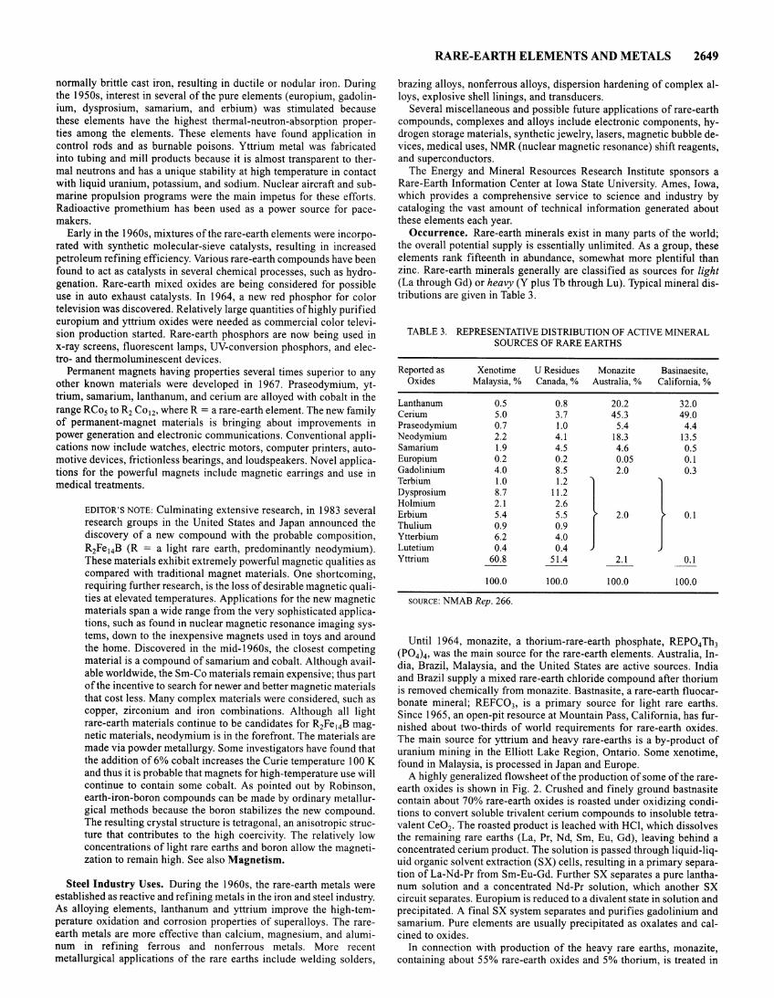
normally brittle cast iron, resulting in ductile or nodular iron. During the 1950s, interest in several of the pure elements (europium, gadolinium, dysprosium, samarium, and erbium) was stimulated because these elements have the highest thermal-neutron-absorption properties among the elements. These elements have found application in control rods and as burnable poisons. Yttrium metal was fabricated into tubing and mill products because it is almost transparent to thermal neutrons and has a unique stability at high temperature in contact with liquid uranium, potassium, and sodium. Nuclear aircraft and submarine propulsion programs were the main impetus for these efforts. Radioactive promethium has been used as a power source for pacemakers.
Early in the 1960s, mixtures of the rare-earth elements were incorporated with synthetic molecular-sieve catalysts, resulting in increased petroleum refining efficiency. Various rare-earth compounds have been found to act as catalysts in several chemical processes, such as hydrogenation. Rare-earth mixed oxides are being considered for possible use in auto exhaust catalysts. In 1964, a new red phosphor for color television was discovered. Relatively large quantities of highly purified europium and yttrium oxides were needed as commercial color television production started. Rare-earth phosphors are now being used in x-ray screens, fluorescent lamps, UV-conversion phosphors, and electro- and thermoluminescent devices.
Permanent magnets having properties several times superior to any other known materials were developed in 1967. Praseodymium, yttrium, samarium, lanthanum, and cerium are alloyed with cobalt in the range RCo5 to R2 Co12, where R = a rare-earth element. The new family of permanent-magnet materials is bringing about improvements in power generation and electronic communications. Conventional applications now include watches, electric motors, computer printers, automotive devices, frictionless bearings, and loudspeakers. Novel applications for the powerful magnets include magnetic earrings and use in medical treatments.
EDITOR'S NOTE: Culminating extensive research, in 1983 several research groups in the United States and Japan announced the discovery of a new compound with the probable composition, R2Fe 14B (R = a light rare earth, predominantly neodymium). These materials exhibit extremely powerful magnetic qualities as compared with traditional magnet materials. One shortcoming, requiring further research, is the loss of desirable magnetic qualities at elevated temperatures. Applications for the new magnetic materials span a wide range from the very sophisticated applications, such as found in nuclear magnetic resonance imaging systems, down to the inexpensive magnets used in toys and around the home. Discovered in the mid-1960s, the closest competing material is a compound of samarium and cobalt. Although available worldwide, the Sm-Co materials remain expensive; thus part of the incentive to search for newer and better magnetic materials that cost less. Many complex materials were considered, such as copper, zirconium and iron combinations. Although all light rare-earth materials continue to be candidates for R2Fe 14B magnetic materials, neodymium is in the forefront. The materials are made via powder metallurgy. Some investigators have found that the addition of 6% cobalt increases the Curie temperature I 00 K and thus it is probable that magnets for high-temperature use will continue to contain some cobalt. As pointed out by Robinson, earth-iron-boron compounds can be made by ordinary metallurgical methods because the boron stabilizes the new compound. The resulting crystal structure is tetragonal, an anisotropic structure that contributes to the high coercivity. The relatively low concentrations of light rare earths and boron allow the magnetization to remain high. See also Magnetism.
Steel Industry Uses. During the 1960s, the rare-earth metals were established as reactive and refining metals in the iron and steel industry. As alloying elements, lanthanum and yttrium improve the high-temperature oxidation and corrosion properties of superalloys. The rareearth metals are more effective than calcium, magnesium, and aluminum in refining ferrous and nonferrous metals. More recent metallurgical applications of the rare earths include welding solders,
RARE-EARTH ELEMENTS AND METALS 2649
brazing alloys, nonferrous alloys, dispersion hardening of complex alloys, explosive shell linings, and transducers.
Several miscellaneous and possible future applications of rare-earth compounds, complexes and alloys include electronic components, hydrogen storage materials, synthetic jewelry, lasers, magnetic bubble devices, medical uses, NMR (nuclear magnetic resonance) shift reagents, and superconductors.
The Energy and Mineral Resources Research Institute sponsors a Rare-Earth Information Center at Iowa State University. Ames, Iowa, which provides a comprehensive service to science and industry by cataloging the vast amount of technical information generated about these elements each year.
Occurrence. Rare-earth minerals exist in many parts of the world; the overall potential supply is essentially unlimited. As a group, these elements rank fifteenth in abundance, somewhat more plentiful than zinc. Rare-earth minerals generally are classified as sources for light (La through Gd) or heavy (Y plus Tb through Lu). Typical mineral distributions are given in Table 3.
TABLE3. REPRESENTATIVE DISTRIBUTION OF ACTIVE MINERAL SOURCES OF RARE EARTHS
Reported as Xenotime U Residues Monazite Basinaesite, Oxides Malaysia,% Canada,% Australia, % California, %
Lanthanum 0.5 0.8 20.2 32.0 Cerium 5.0 3.7 45.3 49.0 Praseodymium 0.7 1.0 5.4 4.4 Neodymium 2.2 4.1 18.3 13.5 Samarium 1.9 4.5 4.6 0.5 Europium 0.2 0.2 0.05 0.1 Gadolinium 4.0 8.5 2.0 0.3 Terbium 1.0 1.2
) ) Dysprosium 8.7 11.2 Holmium 2.1 2.6 Erbium 5.4 5.5 2.0 0.1 Thulium 0.9 0.9 Ytterbium 6.2 4.0 Lutetium 0.4 0.4 Yttrium 60.8 51.4 2.1 0.1
100.0 100.0 100.0 100.0
SOURCE: NMAB Rep. 266.
Until 1964, monazite, a thorium-rare-earth phosphate, REP04 Th3 (P04) 4, was the main source for the rare-earth elements. Australia, India, Brazil, Malaysia, and the United States are active sources. India and Brazil supply a mixed rare-earth chloride compound after thorium is removed chemically from monazite. Bastnasite, a rare-earth fluocarbonate mineral; REFC03, is a primary source for light rare earths. Since 1965, an open-pit resource at Mountain Pass, California, has furnished about two-thirds of world requirements for rare-earth oxides. The main source for yttrium and heavy rare-earths is a by-product of uranium mining in the Elliott Lake Region, Ontario. Some xenotime, found in Malaysia, is processed in Japan and Europe.
A highly generalized flowsheet of the production of some of the rareearth oxides is shown in Fig. 2. Crushed and finely ground bastnasite contain about 70% rare-earth oxides is roasted under oxidizing conditions to convert soluble trivalent cerium compounds to insoluble tetravalent Ce02• The roasted product is leached with HCI, which dissolves the remaining rare earths (La, Pr, Nd, Sm, Eu, Gd), leaving behind a concentrated cerium product. The solution is passed through liquid-liquid organic solvent extraction (SX) cells, resulting in a primary separation ofLa-Nd-Pr from Sm-Eu-Gd. Further SX separates a pure lanthanum solution and a concentrated Nd-Pr solution, which another SX circuit separates. Europium is reduced to a divalent state in solution and precipitated. A final SX system separates and purifies gadolinium and samarium. Pure elements are usually precipitated as oxalates and calcined to oxides.
In connection with production of the heavy rare earths, monazite, containing about 55% rare-earth oxides and 5% thorium, is treated in
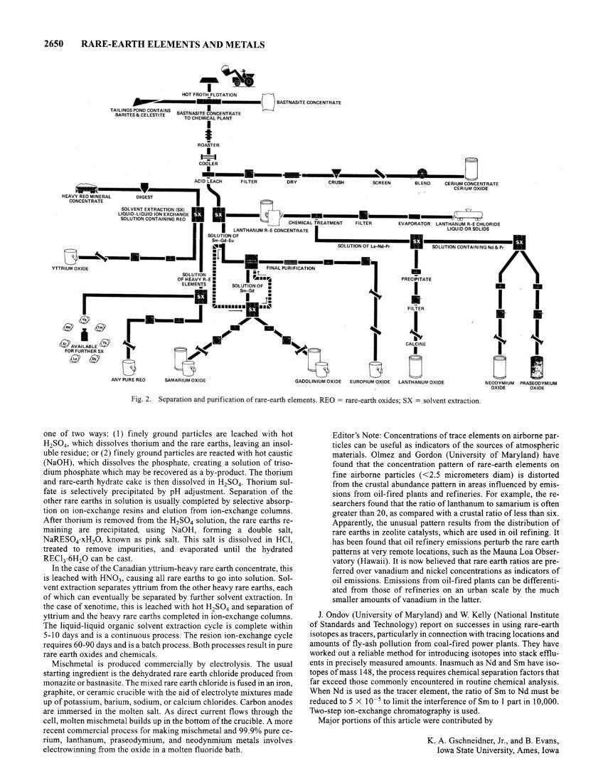
2650 RARE-EARTH ELEMENTS AND METALS
--~ I HOT FROTH FLOTATION 0
~----..-...---- BASTNASITE CONCENTRATe TAILINGS POND CONTAINS I
BARITES. CELESTITE BASJ~~~T~~~~~~i~~~ATE
I I
ROASTER
~
t~----------~---~·--·~-• .. ---0 HEAVa.•ER·A·L---01!~-----AC.I IDCH FILTER ro DRY CRUSH SCREEN 8LENO
CONCENTRATE 1 CERIUM CONCENTRATE
CERIUM OXIDE
SOLVENT EXTRACTION (SXI - - ~ LIOUID-LIOUIDIONEXCHANOE .. ----- -- ·--------!(~
SOLUTION Of .. -~~~~----·11 II SOLUTION CONTAINING JReo I I LANTHANUM R-E coNcEC:T::~:L fi REATMENT FILTER EVAPORATOR LANTL~~~~t'o'li~~~~RIDE
~_,_______ ~;-Eu ll----=;u]-"d-P, SOLUTIONCONTAININONd"P'
YTTRIUM OXIDE ; - FINAL PURIF ICATION I (\ SOLUTION : I ~ L 111!!1
I O~~:.:~~T~-E 5 ,_II 'it PRECr ATe
SO~ON~ : • T T e e 1 e
e AVAILABLE e FOR FURTHER SX
ee ANY PURE REO SAMARIUM OXIDE GADOLINIUM OXIDE EUROPIUM OXIDE
r j j CAL. INE r r D 0 ~
lANTHANUM OXIDE NEODYMIUM PRASEODYMIUM OXIDE OX IDE
Fig. 2. Separation and purification of rare-earth elements. REO= rare-eanh oxides; SX =solvent extraction.
one of two ways: (I) finely ground particles are leached with hot H2S04, which dissolves thorium and the rare earths, leaving an insoluble residue; or (2) finely ground particles are reacted with hot caustic (NaOH), which dissolves the phosphate, creating a solution of trisodium phosphate which may be recovered as a by-product. The thorium and rare-earth hydrate cake is then dissolved in H2S04 . Thorium sulfate is selectively precipitated by pH adjustment. Separation of the other rare earths in solution is usually completed by selective absorption on ion-exchange resins and elution from ion-exchange columns. After thorium is removed from the H2S04 solution, the rare earths remaining are precipitated, using NaOH, forming a double salt, NaRES04·xH20, known as pink salt. This salt is dissolved in HCl, treated to remove impurities, and evaporated until the hydrated REC13·6H20 can be cast.
In the case of the Canadian yttrium-heavy rare earth concentrate, this is leached with HN03, causing all rare earths to go into solution. Solvent extraction separates yttrium from the other heavy rare earths, each of which can eventually be separated by further solvent extraction. In the case of xenotime, this is leached with hot H2S04 and separation of yttrium and the heavy rare earths completed in ion-exchange columns. The liquid-liquid organic solvent extraction cycle is complete within 5-l 0 days and is a continuous process. The resion ion-exchange cycle requires 60-90 days and is a batch process . Both processes result in pure rare earth oxides and chemicals .
Mischmetal is produced commercially by electrolysis. The usual starting ingredient is the dehydrated rare earth chloride produced from monazite or bastnasite. The mixed rare earth chloride is fused in an iron, graphite, or ceramic crucible with the aid of electrolyte mixtures made up of potassium, barium, sodium, or calcium chlorides. Carbon anodes are immersed in the molten salt. As direct current flows through the cell, molten mischmetal builds up in the bottom of the crucible. A more recent commercial process for making mischmetal and 99.9% pure cerium, lanthanum, praseodymium, and neodynmium metals involves electrowinning from the oxide in a molten fluoride bath.
Editor 's Note: Concentrations of trace elements on airborne particles can be useful as indicators of the sources of atmospheric materials. Olmez and Gordon (University of Maryland) have found that the concentration pattern of rare-earth elements on fine airborne particles ( < 2.5 micrometers diam) is distorted from the crustal abundance pattern in areas influenced by emissions from oil-fired plants and refineries. For example, the researchers found that the ratio of lanthanum to samarium is often greater than 20, as compared with a crustal ratio of less than six. Apparently, the unusual pattern results from the distribution of rare earths in zeolite catalysts, which are used in oil refining. It has been found that oil refinery emissions perturb the rare earth patterns at very remote locations, such as the Mauna Loa Observatory (Hawaii). It is now believed that rare earth ratios are preferred over vanadium and nickel concentrations as indicators of oil emissions. Emissions from oil-fired plants can be differentiated from those of refineries on an urban scale by the much smaller amounts of vanadium in the latter.
J. Ondov (University of Maryland) and W. Kelly (National Institute of Standards and Technology) report on successes in using rare-earth isotopes as tracers, particularly in connection with tracing locations and amounts of fly-ash pollution from coal-fired power plants . They have worked out a reliable method for introducing isotopes into stack effluents in precisely measured amounts. Inasmuch as Nd and Sm have isotopes of mass 148, the process requires chemical separation factors that far exceed those commonly encountered in routine chemical analysis. When Nd is used as the tracer element, the ratio of Sm to Nd must be reduced to 5 X 10⁻⁵ to limit the interference of Sm to I part in I 0,000. Two-step ion-exchange chromatography is used.
Major portions of this article were contributed by
K. A. Gschneidner, Jr., and B. Evans, Iowa State University, Ames, Iowa
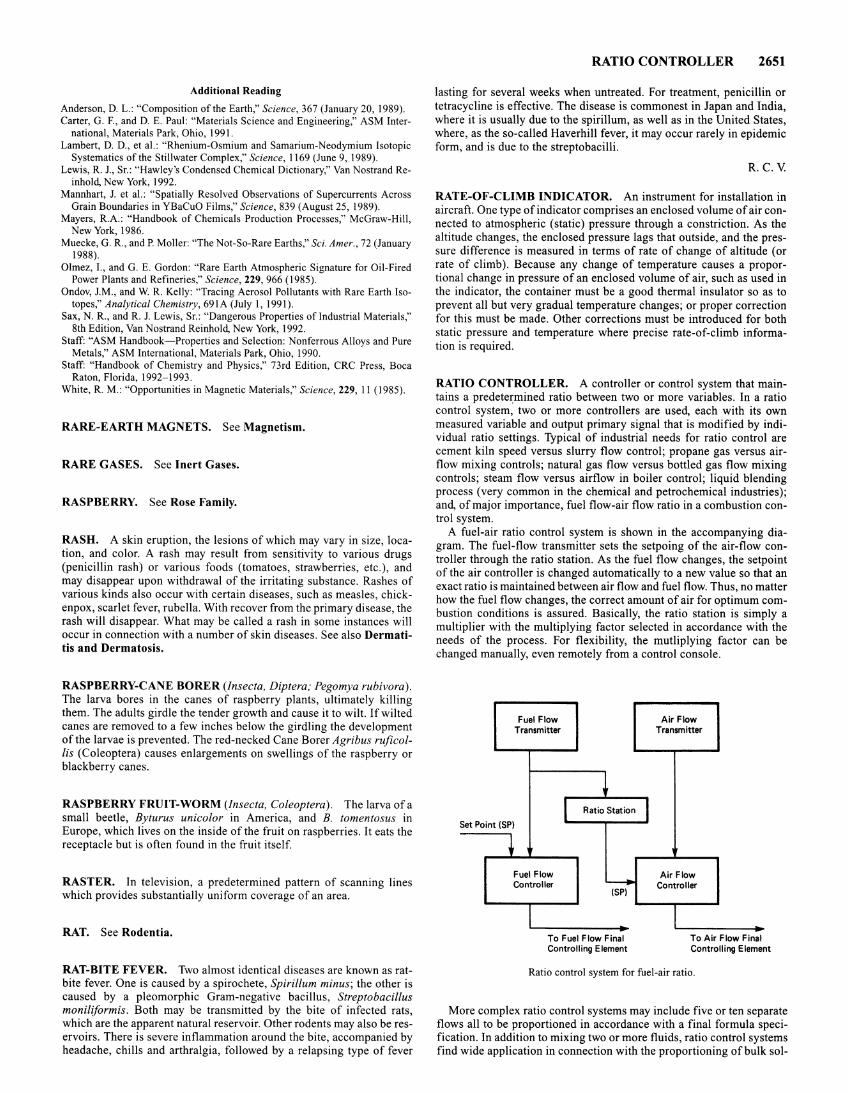
Additional Reading
Anderson, D. L.: "Composition of the Earth," Science, 367 (January 20, 1989). Carter, G. F., and D. E. Paul: "Materials Science and Engineering," ASM Inter
national, Materials Park, Ohio, 1991. Lambert, D. D., et al.: "Rhenium-Osmium and Samarium-Neodymium Isotopic
Systematics of the Stillwater Complex," Science, 1169 (June 9, 1989). Lewis, R. J., Sr.: "Hawley's Condensed Chemical Dictionary," Van Nostrand Re
inhold, New York, 1992. Mannhart, J. et al.: "Spatially Resolved Observations of Supercurrents Across
Grain Boundaries in YBaCuO Films," Science, 839 (August 25, 1989). Mayers, R.A.: "Handbook of Chemicals Production Processes," McGraw-Hill,
New York, 1986. Muecke, G. R., and P. Moller: "The Not-So-Rare Earths," Sci. A mer., 72 (January
1988). Olmez, 1., and G. E. Gordon: "Rare Earth Atmospheric Signature for Oil-Fired
Power Plants and Refineries," Science, 229,966 (1985). Ondov, J.M., and W. R. Kelly: "Tracing Aerosol Pollutants with Rare Earth Iso
topes," Analytical Chemistry, 691A (July I, 1991). Sax, N. R., and R. J. Lewis, Sr.: "Dangerous Properties of Industrial Materials,"
8th Edition, Van Nostrand Reinhold, New York, 1992. Staff: "ASM Handbook-Properties and Selection: Nonferrous Alloys and Pure
Metals," ASM International, Materials Park, Ohio, 1990. Staff: "Handbook of Chemistry and Physics," 73rd Edition, CRC Press, Boca
Raton, Florida, 1992-1993. White, R. M.: "Opportunities in Magnetic Materials," Science, 229, 11 (1985).
RARE-EARTH MAGNETS. See Magnetism.
RARE GASES. See Inert Gases.
RASPBERRY. See Rose Family.
RASH. A skin eruption, the lesions of which may vary in size, location, and color. A rash may result from sensitivity to various drugs (penicillin rash) or various foods (tomatoes, strawberries, etc.), and may disappear upon withdrawal of the irritating substance. Rashes of various kinds also occur with certain diseases, such as measles, chickenpox, scarlet fever, rubella. With recover from the primary disease, the rash will disappear. What may be called a rash in some instances will occur in connection with a number of skin diseases. See also Dermatitis and Dermatosis.
RASPBERRY-CANE BORER (Insecta, Diptera; Pegomya rubivora). The larva bores in the canes of raspberry plants, ultimately killing them. The adults girdle the tender growth and cause it to wilt. If wilted canes are removed to a few inches below the girdling the development of the larvae is prevented. The red-necked Cane Borer Agribus ruficollis (Coleoptera) causes enlargements on swellings of the raspberry or blackberry canes.
RASPBERRY FRUIT-WORM (Insecta, Coleoptera). The larva of a small beetle, Byturus unicolor in America, and B. tomentosus in Europe, which lives on the inside of the fruit on raspberries. It eats the receptacle but is often found in the fruit itself.
RASTER. In television, a predetermined pattern of scanning lines which provides substantially uniform coverage of an area.
RAT. See Rodentia.
RAT-BITE FEVER. Two almost identical diseases are known as ratbite fever. One is caused by a spirochete, Spirillum minus; the other is caused by a pleomorphic Gram-negative bacillus, Streptobacillus moniliformis. Both may be transmitted by the bite of infected rats, which are the apparent natural reservoir. Other rodents may also be reservoirs. There is severe inflammation around the bite, accompanied by headache, chills and arthralgia, followed by a relapsing type of fever
RATIO CONTROLLER 2651
lasting for several weeks when untreated. For treatment, penicillin or tetracycline is effective. The disease is commonest in Japan and India, where it is usually due to the spirillum, as well as in the United States, where, as the so-called Haverhill fever, it may occur rarely in epidemic form, and is due to the streptobacilli.
R.C.V.
RATE-OF-CLIMB INDICATOR. An instrument for installation in aircraft. One type of indicator comprises an enclosed volume of air connected to atmospheric (static) pressure through a constriction. As the altitude changes, the enclosed pressure lags that outside, and the pressure difference is measured in terms of rate of change of altitude (or rate of climb). Because any change of temperature causes a proportional change in pressure of an enclosed volume of air, such as used in the indicator, the container must be a good thermal insulator so as to prevent all but very gradual temperature changes; or proper correction for this must be made. Other corrections must be introduced for both static pressure and temperature where precise rate-of-climb information is required.
RATIO CONTROLLER. A controller or control system that maintains a predetermined ratio between two or more variables. In a ratio control system, two or more controllers are used, each with its own measured variable and output primary signal that is modified by individual ratio settings. Typical of industrial needs for ratio control are cement kiln speed versus slurry flow control; propane gas versus airflow mixing controls; natural gas flow versus bottled gas flow mixing controls; steam flow versus airflow in boiler control; liquid blending process (very common in the chemical and petrochemical industries); and, of major importance, fuel flow-air flow ratio in a combustion control system.
A fuel-air ratio control system is shown in the accompanying diagram. The fuel-flow transmitter sets the setpoing of the air-flow controller through the ratio station. As the fuel flow changes, the setpoint of the air controller is changed automatically to a new value so that an exact ratio is maintained between air flow and fuel flow. Thus, no matter how the fuel flow changes, the correct amount of air for optimum combustion conditions is assured. Basically, the ratio station is simply a multiplier with the multiplying factor selected in accordance with the needs of the process. For flexibility, the mutliplying factor can be changed manually, even remotely from a control console.
Fuel Flow Transmitter
I Set Point (SP)
Ratio Station I
+ Fuel Flow
~ Controller (SP)
To Fuel Flow Final Controlling Element
Air Flow Transmitter
Air Flow Controller
To Air Flow Final Control! ing Element
Ratio control system for fuel-air ratio.
More complex ratio control systems may include five or ten separate flows all to be proportioned in accordance with a final formula specification. In addition to mixing two or more fluids, ratio control systems find wide application in connection with the proportioning of bulk sol-
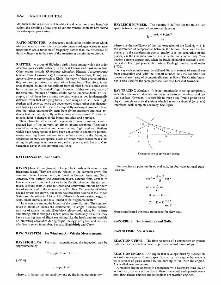
2652 RATIO DETECTOR
ids, such as the ingredients of feedstock and cereal; or in ore beneficication, the blending of raw ores of various mineral contents best suited for subsequent processing.
RATIO DETECTOR. A frequency-modulation discriminator which utilizes the ratio of two intermediate-frequency voltages whose relative magnitudes are a function of frequency, rather than the difference of those voltages as in the case of the Armstrong discriminator circuit.
RATITES. A group of flightless birds (Aves) among which the order Struthioniformes (the ostrich) is the best known and most important. Other orders include Rheiformes (Rheidae; Rheas); Casuariiformes (Casuariidae; Cassowaries); Casuariiformes (Dromaiidae; Emus); and Apterygiformes (Apterygidae; Kiwis). In many of their characteristics, they are more primitive than most other living birds. Therefore, it was once thought that ratites had split off from all other birds at a time when birds had not yet "invented" flight. However, if this were so, many of the structural features of ratites would not be understandable. For example, all of them have a wing skeleton which is not fundamentally different from that of flying birds. Their wings also still bear flight feathers and coverts, hence are degenerated wings rather than degenerated forelegs, as was the case in the bipedally walking dinosaurs. Therefore the ratites undoubtedly stem from flying ancestors and have evidently lost their ability to fly as their body size increased. This has led to considerable changes in the bones, muscles, and plumage.
Their characteristics include degenerated breast muscles; a retrogressed keel of the sternum; an almost absent wishbone (furcula); a simplified wing skeleton and musculature; flight and tail feathers which have retrogressed or have been converted to decorative plumes; strong legs; leg bones without air chambers except in the femur; no separation of pterylae; apteria, a loss of feather vanes which means that oiling the plumage is not necessary; and no preen gland. See also Cassowaries; Emu; Kiwi; Ostrich; and Rhea.
RATTLESNAKES. See Snakes.
RAVEN (Aves, Passeriformes). Large black birds with more or less iridescent luster. They are closely related to the common crow. The common raven, Corvus corax, is found in Europe, Asia, and North America. One variety, the American raven, extends from Canada to Guatemala and from the Rockies to the Pacific. Another, the northern raven, is found from Alaska to Greenland, southward into the northern tier of states, and in the mountains to Carolina. Two species of whitenecked ravens are known, one in the southwestern deserts of the United States and the other in Africa. All of these birds eat carrion, eggs, insects, small animals, and to a limited extent vegetable matter.
The ravens are among the largest of the passeriformes. The common raven is about 25 inches (64 centimeters) in length. General characteristics of ravens include: Blue-black glossy coloration; bill is large and strong; tail is wedged-shaped; nests are preferably on cliffs; they have a soaring type of flight something like the hawk and are capable of interesting acrobatics during flight; the eggs are green and are usually five to seven in number. See also Blackbird; and Crow.
RAWIN SYSTEM. See Wind and Air Velocity Measurements.
RAYLEIGH LAW. For small magnetization, the induction may be approximated by
B = fLoH + vlf2 + · · ·
yielding
fL = fLo+ vH
where fL is the normal permeability and fLo the initial permeability.
RAYLEIGH NUMBER. The quantity R defined for the fluid-filled space between two parallel horizontal planes as
u(e - e )gd3 R = I 2
vk
Where U is the COefficient of thermal expansion of the fluid, 81 - 82 is the difference of temperature between the bottom plane and the top plane, g is the acceleration due to gravity, d is the separation of the planes, v is the kinematic viscosity, k is the thermal conductivity. Convection currents appear only when the Rayleigh number exceeds a critical value. For rigid planes, the critical Rayleigh number is of order 1,700.
A Rayleigh number may be defined for any system of natural (or free) convection and, with the Prandtl number, sets the condition for dynamical similarity of geometrically similar flows. The Grashof number is also used for the same purpose. See also GrashofNumber.
RAY TRACING (Optical). It is not practicable to set up completely accurate equations to describe an image in terms of the object and optical surface. However, it is possible to trace a ray from a point on an object through an optical system which has only spherical (or plane) interfaces, with complete accuracy. See figure.
p p'
Demonstration of optical ray tracing.
For rays from a point on the optical axis, the four conventional equations are
.. R+S . SID 1 = -R-SID r
. n .. SID r =-SID 1
n'
e'=r+S-i
S' = R _ R sin r sine'
More complicated methods are needed for skew rays.
RAZORBILL. See Shorebirds and Gulls.
RAZOR FISH. See Wrasses.
REACTION CURVE. The time response of a component or system is defined as the reaction curve in process control terminology.
REACTION ENGINE. An engine that develops thrust by its reaction to a substance ejected from it; specifically, such an engine that ejects a jet or stream of gases created by the burning of fuel with the engine. Also called reaction motor.
A reaction engine operates in accordance with Newton's third law of motion, i.e., to every action (force) there is an equal and opposite reaction. Both rocket engines and jet engines are reaction engines.
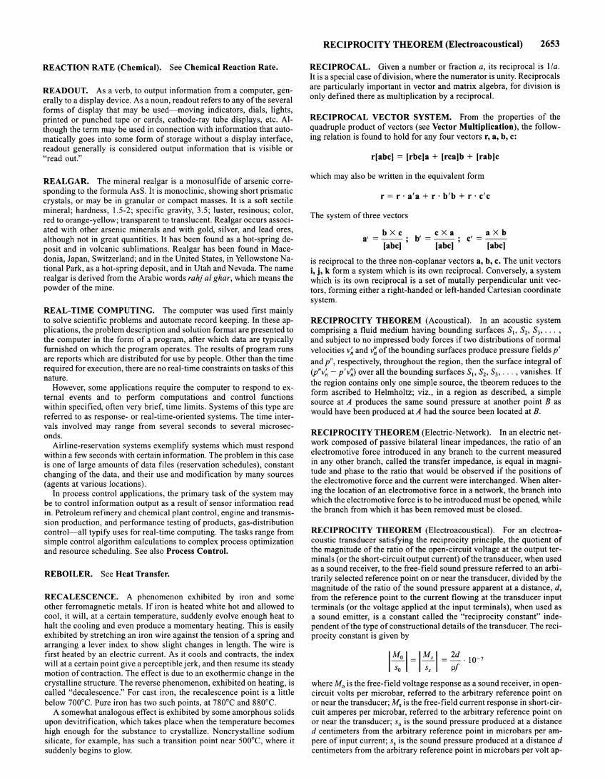
REACTION RATE (Chemical). See Chemical Reaction Rate.
READOUT. As a verb, to output information from a computer, generally to a display device. As a noun, readout refers to any of the several forms of display that may be used-moving indicators, dials, lights, printed or punched tape or cards, cathode-ray tube displays, etc. Although the term may be used in connection with information that automatically goes into some form of storage without a display interface, readout generally is considered output information that is visible or "read out."
REALGAR. The mineral realgar is a monosulfide of arsenic corresponding to the formula AsS. It is monoclinic, showing short prismatic crystals, or may be in granular or compact masses. It is a soft sectile mineral; hardness, 1.5-2; specific gravity, 3.5; luster, resinous; color, red to orange-yellow; transparent to translucent. Realgar occurs associated with other arsenic minerals and with gold, silver, and lead ores, although not in great quantities. It has been found as a hot-spring deposit and in volcanic sublimations. Realgar has been found in Macedonia, Japan, Switzerland; and in the United States, in Yellowstone National Park, as a hot-spring deposit, and in Utah and Nevada. The name realgar is derived from the Arabic words rahj al ghar, which means the powder of the mine.
REAL-TIME COMPUTING. The computer was used first mainly to solve scientific problems and automate record keeping. In these applications, the problem description and solution format are presented to the computer in the form of a program, after which data are typically furnished on which the program operates. The results of program runs are reports which are distributed for use by people. Other than the time required for execution, there are no real-time constraints on tasks of this nature.
However, some applications require the computer to respond to external events and to perform computations and control functions within specified, often very brief, time limits. Systems of this type are referred to as response- or real-time-oriented systems. The time intervals involved may range from several seconds to several microseconds.
Airline-reservation systems exemplify systems which must respond within a few seconds with certain information. The problem in this case is one of large amounts of data files (reservation schedules), constant changing of the data, and their use and modification by many sources (agents at various locations).
In process control applications, the primary task of the system may be to control information output as a result of sensor information read in. Petroleum refinery and chemical plant control, engine and transmission production, and performance testing of products, gas-distribution control-all typify uses for real-time computing. The tasks range from simple control algorithm calculations to complex process optimization and resource scheduling. See also Process Control.
REBOILER. See Heat Transfer.
RECALESCENCE. A phenomenon exhibited by iron and some other ferromagnetic metals. If iron is heated white hot and allowed to cool, it will, at a certain temperature, suddenly evolve enough heat to halt the cooling and even produce a momentary heating. This is easily exhibited by stretching an iron wire against the tension of a spring and arranging a lever index to show slight changes in length. The wire is first heated by an electric current. As it cools and contracts, the index will at a certain point give a perceptible jerk, and then resume its steady motion of contraction. The effect is due to an exothermic change in the crystalline structure. The reverse phenomenon, exhibited on heating, is called "decalescence." For cast iron, the recalescence point is a little below 700°C. Pure iron has two such points, at 780°C and 880°C.
A somewhat analogous effect is exhibited by some amorphous solids upon devitrification, which takes place when the temperature becomes high enough for the substance to crystallize. Noncrystalline sodium silicate, for example, has such a transition point near 500°C, where it suddenly begins to glow.
RECIPROCITY THEOREM (Electroacoustical) 2653
RECIPROCAL. Given a number or fraction a, its reciprocal is !Ia. It is a special case of division, where the numerator is unity. Reciprocals are particularly important in vector and matrix algebra, for division is only defined there as multiplication by a reciprocal.
RECIPROCAL VECTOR SYSTEM. From the properties of the quadruple product of vectors (see Vector Multiplication), the following relation is found to hold for any four vectors r, a, b, c:
r[abc] = [rbc]a + [rca]b + [rab]c
which may also be written in the equivalent form
r = r · a'a + r · b'b + r · c'c
The system of three vectors
bXc cXa a'=--· b' =--;
[abc] ' [abc]
aXb c'=--
[abc]
is reciprocal to the three non-coplanar vectors a, b, c. The unit vectors i, j, k form a system which is its own reciprocal. Conversely, a system which is its own reciprocal is a set of mutally perpendicular unit vectors, forming either a right-handed or left-handed Cartesian coordinate system.
RECIPROCITY THEOREM (Acoustical). In an acoustic system comprising a fluid medium having bounding surfaces S1, S2, S3, ... ,
and subject to no impressed body forces if two distributions of normal velocities v~ and v'~ of the bounding surfaces produce pressure fields p' and p", respectively, throughout the region, then the surface integral of (p"v~ - p'v'~) over all the bounding surfaces S~o S2, S3, ... , vanishes. If the region contains only one simple source, the theorem reduces to the form ascribed to Helmholtz; viz., in a region as described, a simple source at A produces the same sound pressure at another point B as would have been produced at A had the source been located at B.
RECIPROCITY THEOREM (Electric-Network). In an electric network composed of passive bilateral linear impedances, the ratio of an electromotive force introduced in any branch to the current measured in any other branch, called the transfer impedance, is equal in magnitude and phase to the ratio that would be observed if the positions of the electromotive force and the current were interchanged. When altering the location of an electromotive force in a network, the branch into which the electromotive force is to be introduced must be opened, while the branch from which it has been removed must be closed.
RECIPROCITY THEOREM (Electroacoustical). For an electroacoustic transducer satisfying the reciprocity principle, the quotient of the magnitude of the ratio of the open-circuit voltage at the output terminals (or the short-circuit output current) of the transducer, when used as a sound receiver, to the free-field sound pressure referred to an arbitrarily selected reference point on or near the transducer, divided by the magnitude of the ratio of the sound pressure apparent at a distance, d, from the reference point to the current flowing at the transducer input terminals (or the voltage applied at the input terminals), when used as a sound emitter, is a constant called the "reciprocity constant" independent of the type of constructional details of the transducer. The reciprocity constant is given by
1:0 I= l:s I 2d =-. lQ-7
pf
where M 0 is the free-field voltage response as a sound receiver, in opencircuit volts per microbar, referred to the arbitrary reference point on or near the transducer; M, is the free-field current response in short-circuit amperes per microbar, referred to the arbitrary reference point on or near the transducer; s0 is the sound pressure produced at a distance d centimeters from the arbitrary reference point in microbars per ampere of input current; s, is the sound pressure produced at a distance d centimeters from the arbitrary reference point in micro bars per volt ap-
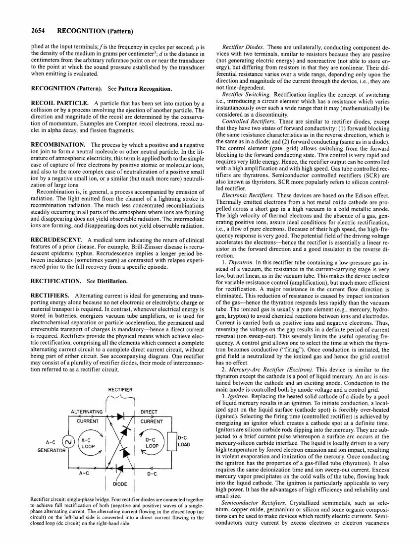
2654 RECOGNITION (Pattern)
plied at the input terminals ;lis the frequency in cycles per second; p is the density of the medium in grams per centimeter3; dis the distance in centimeters from the arbitrary reference point on or near the transducer to the point at which the sound pressure established by the transducer when emitting is evaluated.
RECOGNITION (Pattern). See Pattern Recognition.
RECOIL PARTICLE. A particle that has been set into motion by a collision or by a process involving the ejection of another particle. The direction and magnitude of the recoil are determined by the conservation of momentum. Examples are Compton recoil electrons, recoil nuclei in alpha decay, and fission fragments .
RECOMBINATION. The process by which a positive and a negative ion join to form a neutral molecule or other neutral particle. In the literature of atmospheric electricity, this term is applied both to the simple case of capture of free electrons by positive atomic or molecular ions, and also to the more complex case of neutralization of a positive small ion by a negative small ion, or a similar (but much more rare) neutralization of large ions .
Recombination is, in general, a process accompanied by emission of radiation. The light emitted from the channel of a lightning stroke is recombination radiation. The much less concentrated recombinations steadily occurring in all parts of the atmosphere where ions are forming and disappearing does not yield observable radiation. The intermediate ions are forming, and disappearing does not yield observable radiation .
RECRUDESCENT. A medical term indicating the return of clinical features of a prior disease . For example, Brili-Zinsser disease is recrudescent epidemic typhus. Recrudescence implies a longer period between incidences (sometimes years) as contrasted with relapse experienced prior to the full recovery from a specific episode.
RECTIFICATION. See Distillation.
RECTIFIERS. Alternating current is ideal for generating and transporting energy alone because no net electronic or electrolytic charge or material transport is required. In contrast, whenever electrical energy is stored in batteries, energizes vacuum tube amplifiers, or is used for electrochemical separation or particle acceleration, the permanent and irreversible transport of charges is mandatory-hence a direct current is required. Rectifiers provide the physical means which achieve electric rectification, comprising all the elements which connect a complete alternating current circuit to a complete direct current circuit, without being part of either circuit. See accompanying diagram. One rectifier may consist of a plurality of rectifier diodes, their mode of interconnection referred to as a rectifier circuit.
RECTIFIER
ALTERNATING
1('-/~ DIRECT
CURRENT I CURRENT
~) 8 D-C A -C N LOAD
GENERATOR p p
I A-C D-C
I DIODE
Rectifier circuit: single-phase bridge. Four rectifier diodes are connected together to achieve full rectification of both (negative and positive) waves of a singlephase alternating current. The alternating current flowing in the closed loop (ac circuit) on the left-hand side is converted into a direct current flowing in the closed loop (de circuit) on the right-hand side.
Rectifier Diodes. These are unilaterally, conducting component devices with two terminals, similar to resistors because they are passive (not generating electric energy) and nonreactive (not able to store energy), but differing from resistors in that they are nonlinear. Their differential resistance varies over a wide range, depending only upon the direction and magnitude of the current through the device, i.e., they are not time-dependent.
Rectifier Switching. Rectification implies the concept of switching i.e., introducing a circuit element which has a resistance which varies instantaneously over such a wide range that it may (mathematically) be considered as a discontinuity.
Controlled Rectifiers. These are similar to rectifier diodes, except that they have two states offorward conductivity: (I) forward blocking (the same resistance characteristics as in the reverse direction, which is the same as in a diode; and (2) forward conducting (same as in a diode) . The control element (gate, grid) allows switching from the forward blocking to the forward conducting state. This control is very rapid and requires very little energy. Hence, the rectifier output can be controlled with a high amplification and with high speed. Gas tube controlled rectifiers are thyratrons. Semiconductor controlled rectifiers (SCR) are also known as thyristors. SCR more popularly refers to silicon controlled rectifier.
Electronic Rectifiers. These devices are based on the Edison effect. Thermally emitted electrons from a hot metal oxide cathode are propelled across a short gap in a high vacuum to a cold metallic anode . The high velocity of thermal electrons and the absence of a gas, generating positive ions, assure ideal conditions for electric rectification, i.e., a flow of pure electrons. Because of their high speed, the high-frequency response is very good. The potential field of the driving voltage accelerates the electrons-hence the rectifier is essentially a linear resistor in the forward direction and a good insulator in the reverse direction.
1. Thyratron. In this rectifier tube containing a low-pressure gas instead of a vacuum, the resistance in the current-carrying stage is very low, but not linear, as in the vacuum tube. This makes the device useless for variable resistance control (amplification), but much more efficient for rectification . A major resistance in the current flow direction is eliminated. This reduction of resistance is caused by impact ionization of the gas-hence the thyratron responds less rapidly than the vacuum tube. The ionized gas is usually a pure element (e.g., mercury, hydrogen, krypton) to avoid chemical reactions between ions and electrodes. Current is carried both as positive ions and negative electrons. Thus, reversing the voltage on the gap results in a definite period of current reversal (ion sweep-out). This severely limits the useful operating frequency. A control grid allows one to select the time at which the thyratron becomes conductive ("firing"). Once conduction is initiated, the grid field is neutralized by the ionized gas and hence the grid control has no effect.
2. Mercury-Arc Rectifier (Excitron) . This device is similar to the thyratron except the cathode is a pool of liquid mercury. An arc is sustained between the cathode and an exciting anode. Conduction to the main anode is controlled both by anode voltage and a control grid.
3. Ignitron. Replacing the heated solid cathode of a diode by a pool of liquid mercury results in an ignitron. To initiate conduction, a localized spot on the liquid surface (cathode spot) is forcibly over-heated (ignited). Selecting the firing time (controlled rectifier) is achieved by energizing an ignitor which creates a cathode spot at a definite time. Ignitors are silicon carbide rods dipping into the mercury. They are subjected to a brief current pulse whereupon a surface arc occurs at the mercury-silicon carbide interface. The liquid is locally driven to a very high temperature by forced electron emission and ion impact, resulting in violent evaporation and ionization of the mercury. Once conducting the ignitron has the properties of a gas-filled tube (thyratron) . It also requires the same deionization time and ion sweep-out current. Excess mercury vapor precipitates on the cold walls of the tube, flowing back into the liquid cathode. The ignitron is particularly applicable to very high power. It has the advantages of high efficiency and reliability and small size.
Semiconductor Rectifiers. Crystallized semimetals, such as selenium, copper oxide, germanium or silicon and some organic compositions can be used to make devices which rectify electric currents. Semiconductors carry current by excess electrons or electron vacancies
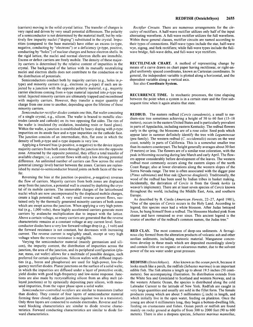
(carriers) moving in the solid crystal lattice. The transfer of charges is very rapid and driven by very small potential differences. The polarity of a semiconductor is not determined by the material itself, but by relatively few impurity nuclei ("doping") substituted in the crystal. Impurities (compared to the base material) have either an excess (n-type, negative, conducting by "electrons") or a deficiency (p-type, positive, conducting by "holes") of nuclear charges and hence electron shells. In the rigid lattice, the nuclei and normal electron shells are immobile. Excess or defect carriers are freely mobile. The density of these majority carriers is determined by the relative content of impurities in the crystal. The background of the lattice with its mutually neutralizing nuclei and electron shells does not contribute to the conduction or to the distribution of potentials.
Semiconductors conduct both by majority carriers (e.g., holes in ptype) and minority carriers (e.g., electrons in p-type) if such are injected by a junction with the opposite polarity material, e.g., majority carrier electrons coming from n-type material injected into p-type material. Injected minority carriers are ultimately trapped and recombined with majority carriers. However, they transfer a major quantity of charge from one zone to another, depending upon the lifetime of these minority carriers.
Semiconductor rectifier diodes contain one thin, flat wafer consisting of a single crystal, e.g., silicon. The wafer is brazed to metallic electrodes (anode and cathode) on its two opposing flat sides. The rim of the wafer is insulated (by oxidation, insulating resin or fused glass). Within the wafer, a junction is established by heavy doping withp-type impurities on its anode face and n-type impurities on the cathode face. The junction consists of an intermediate, thin, flat zone in which the density of both p-type and n-type dopants is very low.
Applying a forward bias (p-positive, n-negative) to the device injects majority carriers from both zones through the junction into the opposite zone. Attracted by the opposite potential, they effect a total transfer of available charges; i.e., a current flows with only a low driving potential difference. An unlimited number of carriers can flow across the small potential (energy level) barrier between the zones. Carriers are replenished by metal-to-semiconductor brazed joints on both faces of the wafer.
Reversing the bias at the junction (n-positive, p-negative) reverses the flow of carriers. Majority carriers from both zones are displaced away from the junction, a potential wall is created by depleting the crystal of its mobile carriers. The immovable charges of the latticebound nuclei which are now uncompensated by the displaced mobile charges, create a high potential wall. A very small reverse current flows, sustained only by the thermally generated minority carriers of both zones which are swept across the junction. When applying a very high potential (e.g., 1,000 volts), these highly accelerated carriers generate more carriers by avalanche multiplication due to impact with the lattice. Above a certain voltage, so many carriers are generated that the reverse characteristic remains at a constant voltage at any current level. Semiconductor diodes have a very low forward voltage drop (e.g., I volt) and the forward resistance is not constant, but decreases with increasing current. The reverse current is negligibly small, except at very high voltage where the reverse resistance is negligible.
Varying the semiconductor material (mainly germanium and silicon), the impurity content, the distribution of impurities across the junction, the area of the junction, and its peripheral configuration (planar, mesa, cut wafer) allows for a multitude of possible designs, each preferred for certain applications. Silicon wafers with diffused impurities (e.g., boron and phosphorus) are used for high-power, low-frequency rectifier diodes. Planar junctions on the surface of a solid wafer, in which the impurities are diffused under a layer of protective oxide, yield diodes with good high-frequency and low-noise response. Junctions are also made by recrystallizing silicon from an alloy melt (alloyed junctions) or by epitaxially depositing pure silicon, with measured impurities, from the vapor phase upon a solid wafer.
Semiconductor-controlled rectifiers are similar to transistors (rather than diodes). They consist of four layers of semiconductor material forming three closely adjacent junctions (against two in a transistor). Only three layers are connected to outside electrodes. Reverse and forward blocking characteristics are similar to diode reverse characteristics. Forward conducting characteristics are similar to diode forward characteristics.
REDFISH (Osteichthyes) 2655
Rectifier Circuits. There are numerous arrangements for the circuitry of rectifiers. A half-wave rectifier utilizes only half of the input alternating waveform. A full-wave rectifier utilizes the full waveform. Within these general classes, rectifier circuits are named according to their types of connections. Half-wave types include the star, half-wave wye, zigzag, and fork rectifiers; while full-wave types include the fullwave bridge, full-wave delta, and full-wave wye rectifiers.
RECTILINEAR CHART. A method of representing change by means of a curve drawn on chart paper having rectilinear, or right-angled uniformly spaced coordinates, known as Cartesian coordinates. In general, the independent variable is plotted along a horizontal, and the dependent variable along a vertical axis.
See also Coordinate System.
RECURRENCE TIME. In stochastic processes, the time elapsing between the point when a system is in a certain state and the first subsequent time when it again attains that state.
REDBUD. The eastern redbud (Cercis canadensis), a small to medium-size tree sometimes achieving a height of 50 to 60 feet (15-18 meters), occurs in the eastern United States and is particularly prevalent in parts of Appalachia, including eastern Kentucky. The redbud flowers early in the spring; the blossoms are of a rose color. Seed pods which appear later in summer definitely identify the tree with Leguminosae (pea family). The western redbud (C. occidentalis) occurs on the west coast, notably in parts of California. This is a somewhat smaller tree than its eastern counterpart. The height generally averages about 30 feet (9 meters) or less. The flowers are of a similar rose coloration, with the peak in blooming occuring during late March and early April. The flowers appear considerably before development of the leaves. The western redbud most commonly occurs along the eastern slopes of the north Coast Range; also at lower elevations along the western slopes of the Sierra Nevada range. The tree is often associated with the digger pine (Pinus sabiniana) and blue oak (Quercus douglasii). Traditionally, the wood of the redbud has been used by Indian tribes in basket making. Incidentally, the derivation of Cercis is from the Greek kerkis (a weaver's implement). There are at least seven species of Cercis known throughout the world, including the Middle East, Asia, and southern Europe.
As described by B. Ciesla (American Forests, 22-27, April 1981 ), "One of the species of Cercis occurs in the Holy Land. According to legend, this species once had a white blossom. After Judas betrayed Jesus, he hung himself from a redbud. The blossoms blushed pink from shame and have remained so ever since. This ancient legend is the source of another of the redbud's common names, the Judas tree."
RED CLAY. The most common of deep-sea sediments. A ferruginous clay formed from the alteration products of volcanic ash and other aeolian sediments, including meteoric material. Manganese concretions develop in these muds which are deposited exceedingly slowly and contain little or no organic or calcareous matter, due to the solvent power of the sea water under great pressure.
RED FISH (Osteichthyes). Also known as the ocean perch, because it looks much like a perch, the redfish (Sebastes marinus) is an important edible fish. The fish attains a length up to about 19.5 inches (50 centimeters). See accompanying illustration. Its distribution extends from the White Sea and Greenland to Scotland and western Norway, and in the western Atlantic Ocean, the species is distributed along the cold Labrador Current to the latitude of New York. Redfish are caught in very large quantities and usually are sold in the fillet form. The female produces young which are about 5 millimeters G inch) in length, and which initially live in the open water, feeding on plankton. Once the young are about 6 millimeters long, they begin a bottom-dwelling life, feeding on crustaceans and fishes. Ocean perch or redfish are found mainly on rocky ground at depths of from 300 to 2000 feet (90 to 600 meters). There is also a deepsea species, Sebastes marinus mantellus,
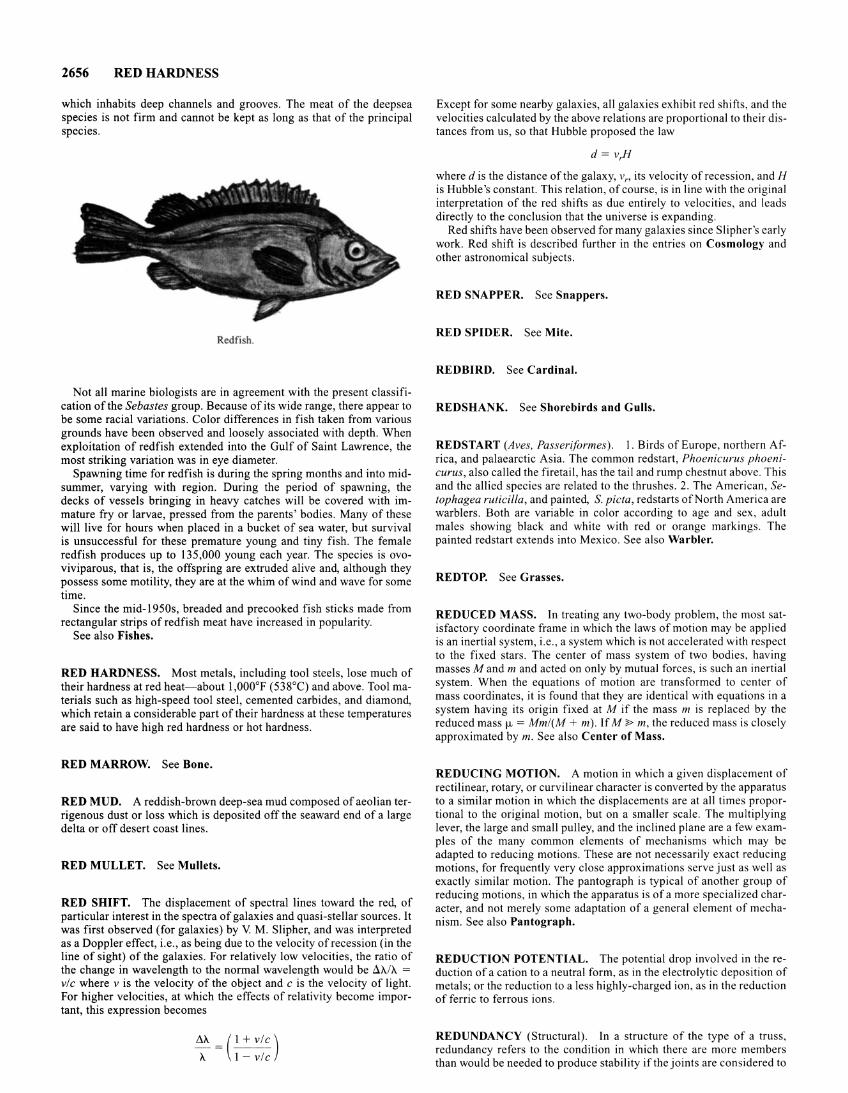
2656 RED HARDNESS
which inhabits deep channels and grooves. The meat of the deepsea species is not firm and cannot be kept as long as that of the principal species.
Redfi h.
Not all marine biologists are in agreement with the present classification of the Sebastes group. Because of its wide range, there appear to be some racial variations. Color differences in fish taken from various grounds have been observed and loosely associated with depth. When exploitation of redfish extended into the Gulf of Saint Lawrence, the most striking variation was in eye diameter.
Spawning time for redfish is during the spring months and into midsummer, varying with region. During the period of spawning, the decks of vessels bringing in heavy catches will be covered with immature fry or larvae, pressed from the parents' bodies. Many of these will live for hours when placed in a bucket of sea water, but survival is unsuccessful for these premature young and tiny fish. The female redfish produces up to 135,000 young each year. The species is ovoviviparous, that is, the offspring are extruded alive and, although they possess some motility, they are at the whim of wind and wave for some time.
Since the mid-1950s, breaded and precooked fish sticks made from rectangular strips of redfish meat have increased in popularity.
See also Fishes.
RED HARDNESS. Most metals, including tool steels, lose much of their hardness at red heat- about 1,000°F (538°C) and above. Tool materials such as high-speed tool steel, cemented carbides, and diamond, which retain a considerable part of their hardness at these temperatures are said to have high red hardness or hot hardness.
RED MARROW. See Bone.
RED MUD. A reddish-brown deep-sea mud composed of aeolian terrigenous dust or loss which is deposited off the seaward end of a large delta or off desert coast lines.
RED MULLET. See Mullets.
RED SHIFT. The displacement of spectral lines toward the red, of particular interest in the spectra of galaxies and quasi-stellar sources. It was first observed (for galaxies) by V M. Slipher, and was interpreted as a Doppler effect, i.e., as being due to the velocity of recession (in the line of sight) of the galaxies. For relatively low velocities, the ratio of the change in wavelength to the normal wavelength would be llA.IA. = vic where v is the velocity of the object and c is the velocity of light. For higher velocities, at which the effects of relativity become important, this expression becomes
llA.=(l+vlc) A. 1- vic
Except for some nearby galaxies, all galaxies exhibit red shifts, and the velocities calculated by the above relations are proportional to their distances from us, so that Hubble proposed the law
d= v,H
where dis the distance of the galaxy, v" its velocity of recession, and H is Hubble's constant. This relation, of course, is in line with the original interpretation of the red shifts as due entirely to velocities, and leads directly to the conclusion that the universe is expanding.
Red shifts have been observed for many galaxies since Slipher's early work. Red shift is described further in the entries on Cosmology and other astronomical subjects.
RED SNAPPER. See Snappers.
RED SPIDER. See Mite.
REDBIRD. See Cardinal.
REDSHANK. See Shorebirds and Gulls.
REDSTART (Aves, Passeriformes). l. Birds of Europe, northern Africa, and palaearctic Asia. The common redstart, Phoenicurus phoenicurus, also called the firetail, has the tail and rump chestnut above. This and the allied species are related to the thrushes. 2. The American, Setophagea ruticilla, and painted, S. picta, redstarts of North America are warblers. Both are variable in color according to age and sex, adult males showing black and white with red or orange markings. The painted redstart extends into Mexico. See also Warbler.
REDTOP. See Grasses.
REDUCED MASS. In treating any two-body problem, the most satisfactory coordinate frame in which the laws of motion may be applied is an inertial system, i.e., a system which is not accelerated with respect to the fixed stars. The center of mass system of two bodies, having masses M and m and acted on only by mutual forces, is such an inertial system. When the equations of motion are transformed to center of mass coordinates, it is found that they are identical with equations in a system having its origin fixed at M if the mass m is replaced by the reduced mass fL = Mmi(M + m). If M :P m, the reduced mass is closely approximated by m. See also Center of Mass.
REDUCING MOTION. A motion in which a given displacement of rectilinear, rotary, or curvilinear character is converted by the apparatus to a similar motion in which the displacements are at all times proportional to the original motion, but on a smaller scale. The multiplying lever, the large and small pulley, and the inclined plane are a few examples of the many common elements of mechanisms which may be adapted to reducing motions. These are not necessarily exact reducing motions, for frequently very close approximations serve just as well as exactly similar motion. The pantograph is typical of another group of reducing motions, in which the apparatus is of a more specialized character, and not merely some adaptation of a general element of mechanism. See also Pantograph.
REDUCTION POTENTIAL. The potential drop involved in thereduction of a cation to a neutral form, as in the electrolytic deposition of metals; or the reduction to a less highly-charged ion, as in the reduction of ferric to ferrous ions.
REDUNDANCY (Structural). In a structure of the type of a truss, redundancy refers to the condition in which there are more members than would be needed to produce stability if the joints are considered to
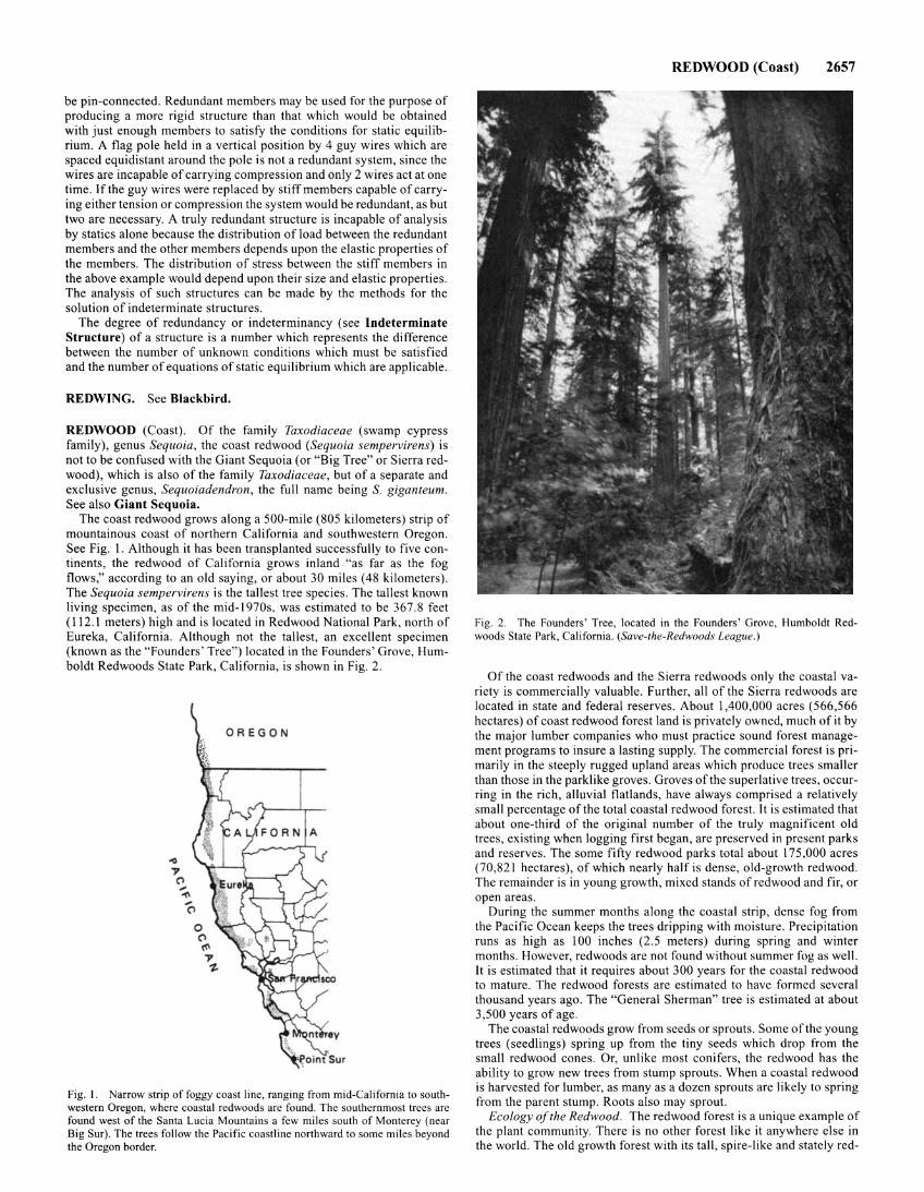
be pin-connected. Redundant members may be used for the purpose of producing a more rigid structure than that which would be obtained with just enough members to satisfy the conditions for static equilibrium. A flag pole held in a vertical position by 4 guy wires which are spaced equidistant around the pole is not a redundant system, since the wires are incapable of carrying compression and only 2 wires act at one time. If the guy wires were replaced by stiff members capable of carrying either tension or compression the system would be redundant, as but two are necessary. A truly redundant structure is incapable of analysis by statics alone because the distribution of load between the redundant members and the other members depends upon the elastic properties of the members. The distribution of stress between the stiff members in the above example would depend upon their size and elastic properties. The analysis of such structures can be made by the methods for the solution of indeterminate structures.
The degree of redundancy or indeterminancy (see Indeterminate Structure) of a structure is a number which represents the difference between the number of unknown conditions which must be satisfied and the number of equations of static equilibrium which are applicable.
REDWING. See Blackbird.
REDWOOD (Coast). Of the family Taxodiaceae (swamp cypress family), genus Sequoia, the coast redwood (Sequoia sempervirens) is not to be confused with the Giant Sequoia (or "Big Tree" or Sierra redwood), which is also of the family Taxodiaceae, but of a separate and exclusive genus, Sequoiadendron, the full name being S. giganteum. See also Giant Sequoia.
The coast redwood grows along a 500-mile (805 kilometers) strip of mountainous coast of northern California and southwestern Oregon. See Fig. I. Although it has been transplanted successfully to five continents, the redwood of California grows inland "as far as the fog flows," according to an old saying, or about 30 miles (48 kilometers). The Sequoia sempervirens is the tallest tree species. The tallest known living specimen, as of the mid-1970s, was estimated to be 367.8 feet ( 112.1 meters) high and is located in Redwood National Park, north of Eureka, California. Although not the tallest, an excellent specimen (known as the "Founders' Tree") located in the Founders' Grove, Humboldt Redwoods State Park, California, is shown in Fig. 2.
OREGON
Fig. I. Narrow strip of foggy coast line, ranging from mid-Cali fornia to southwestern Oregon, where coastal redwoods are found . The southernmost trees are found west of the Santa Lucia Mountains a few miles south of Monterey (near Big Sur). The trees follow the Pacific coastline northward to some miles beyond the Oregon border.
REDWOOD (Coast) 2657
Fig. 2. The Founders' Tree, located in the Founders' Grove, Humboldt Redwoods State Park, California. (Save-the-Redwoods League.)
Of the coast redwoods and the Sierra redwoods only the coastal variety is commercially valuable. Further, all of the Sierra redwoods are located in state and federal reserves. About I ,400,000 acres (566,566 hectares) of coast redwood forest land is privately owned, much of it by the major lumber companies who must practice sound forest management programs to insure a lasting supply. The commercial forest is primarily in the steeply rugged upland areas which produce trees smaller than those in the parklike groves. Groves of the superlative trees, occurring in the rich, alluvial flatlands, have always comprised a relatively small percentage of the total coastal redwood forest. It is estimated that about one-third of the original number of the truly magnificent old trees, existing when logging first began, are preserved in present parks and reserves. The some fifty redwood parks total about 175,000 acres (70,821 hectares), of which nearly half is dense, old-growth redwood. The remainder is in young growth, mixed stands of redwood and fir, or open areas.
During the summer months along the coastal strip, dense fog from the Pacific Ocean keeps the trees dripping with moisture. Precipitation runs as high as 100 inches (2.5 meters) during spring and winter months. However, redwoods are not found without summer fog as well. It is estimated that it requires about 300 years for the coastal redwood to mature. The redwood forests are estimated to have formed several thousand years ago. The "General Sherman" tree is estimated at about 3,500 years of age.
The coastal redwoods grow from seeds or sprouts. Some of the young trees (seedlings) spring up from the tiny seeds which drop from the small redwood cones. Or, unlike most conifers, the redwood has the ability to grow new trees from stump sprouts. When a coastal redwood is harvested for lumber, as many as a dozen sprouts are likely to spring from the parent stump. Roots also may sprout.
Ecology of the Redwood. The redwood forest is a unique example of the plant community. There is no other forest like it anywhere else in the world. The old growth forest with its tall, spire-like and stately red-
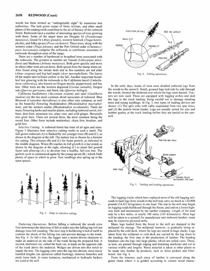
2658 REDWOOD (Coast)
woods has been termed an "unforgettable sight" by numerous tree authorities. The lush green carpet of ferns, trillium, and other small plants of the undergrowth contribute to the air of fantasy of the redwood forest. Redwoods have a number of interesting species of trees growing with them. Some of the major trees are Douglas fir (Pseudotsuga menziessi), Grand fir (Abies grandis), western hemlock (Tsuga heterophylla), and Sitka spruce (Picea sitchensis). These trees, along with the western cedar (Thuja plicata), and the Port Orford cedar (Chamaecyparis lawsoniana) comprise the softwood, or coniferous associates of redwoods throughout most of the range.
There are a number of hardwood or broadleaf trees associated with the redwoods. The greatest in number are Tanoak (Lithocarpus densiflora) and Madrone (Arbutus menziessi). Both grow quickly and move in where other trees are cut down. Both sprout from the stump when cut. Also found along the stream beds and in few numbers are red alder (Alnus oregona) and big-leaf maple (Acer macrophyllum). The leaves of the maple turn brilliant yellow in the fall. Another important broadleaf tree growing with the redwoods is the California laurel ( Umbellularia californica), also known as Oregon myrtle, pepperwood, and bay tree. Other trees are the western dogwood (Corn us nuttallii), Oregon oak (Quercus garryana), and black oak (Quercus kellogii).
California huckleberry ( Vaccinium ovatum) and sal a! (Gaultheria shallon) are the two most common shrub associates of redwood. Blue Blossom (Ceanothus thyrsiflorus) is also often very common, as well as the beautiful flowering rhododendron (Rhododendron macrophyllum), and the western azalea (Rhododendron occidentale). There are many flowering herbs and smaller plants, including redwood sorrel, trillium, deer-foot, mountain iris, alum root, and wild ginger. Horsetails also grow here. There are several ferns, the most common being the sword fern. Other ferns include maidenhair, chain fern, bracken, and gold fern.
Selective Cutting. A redwood forest has trees of all ages and sizes. Figure 3 illustrates how selective cutting works in such a stand. The full-grown redwood (A) is flanked by two younger trees (B) and (C), as shown in the diagram at the left. The mature tree is chosen by a forester for cutting. This releases (B) and (C) for faster growth, as indicated in the middle diagram. When (B) reaches its full growth it is harvested, as shown by the diagram at the right, allowing (C) to attain full growth faster and allowing (A 1) to develop into a healthy, full-size tree. The growth cycle is commenced again by the young sprout (B 1) which finds plenty of space in which to grow. New seedlings also spring up in the open spaces.
l C B
. i \ A,
8 c c
Fig. 3. tep in selective cutting.
Timbering Operations. Before falling a redwood, the woods crew first determines the direction of fall to make sure the falling log will not damage trees left standing. The next step is bulldozing a bed of earth to cushion the shock of the falling tree and prevent damage to the trunk. See Fig. 4. To fall a tree, the logger uses a motor-driven chainsaw to make an undercut on the side of the trunk facing the prepared bed. A second, shallower cut, called the back cut, is made on the opposite side of the trunk above the undercut. Wedges are driven into this notch to topple the tree. The logging crew saws the log into shorter, more easily handled lengths (an operation called bucking); removes branches and peels loose bark. In some instances, mechanical or hydraulic barkers are used at the mill .
Oli!~C:TION 0~ ~ALL
W!;DGE
Fig. 4. Falling operation .
In the early days, teams of oxen once skidded redwood logs from the woods to the sawmill. Small, greased Jogs laid side by side through the woods, formed the skidroad over which the logs were hauled. Tractors are now used. These are equipped with logging arches and skid the logs to the truck landing, being careful not to damage standing trees and young seedlings. In Fig. 5, two types of loading devices are shown: (I) The split yoke with cable suspended from two spar trees; and (2) the mobile boom loader. Logs are usually sorted for size and lumber quality at the truck landing before they are hauled to the sawmill.
Fig. 5. Yarding and loading operation .
The logging trucks which have replaced most of the old logging railroads to haul logs from woods to the mill may carry as much as 120,000 pounds (54,432 kilograms) in one load. The trip to the mill may begin on logging roads bulldozed through the forest, and end on a forest highway built and maintained by the lumber company. Length of the haul may be a few miles, or nearly 100 miles (161 kilometers). Most logs will be taken to a sawmill for manufacture into redwood lumber; some may be routed to plywood mills.
Many logs hauled from the forest to the mill are dumped in the millpond for storage. The millpond, however, is gradually being replaced by the cold deck, where the Jogs are stored in huge stacks. Logs taken from the millpond or cold deck are carried by the log chain to the headrig, the first step in the production of lumber. The headrig handsaw cuts the logs into large planks, which are called cants. These, in turn, are passed through edging and trimming machines and cut to various widths and lengths. Waste material is taken to other plants to be made into lumber by-products, such as fence pickets and fiberboard. See Fig. 6.
From the trimmer, each piece of lumber is conveyed along the green chain where it is graded according to certain wood charac-
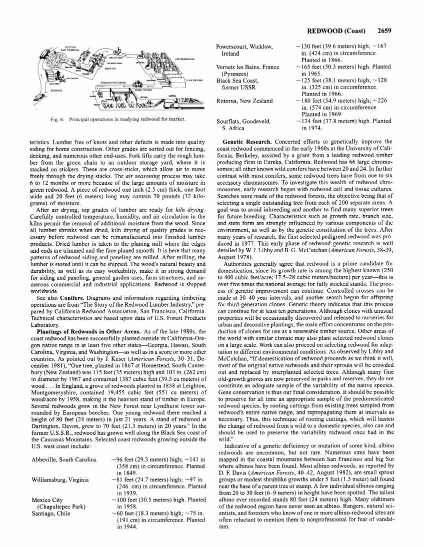
Fig. 6. Principal operations in readying redwood for market.
teristics. Lumber free of knots and other defects is made into quality siding for home construction. Other grades are sorted out for fencing, decking, and numerous other end-uses. Fork lifts carry the rough lumber from the green chain to an outdoor storage yard, where it is stacked on stickers. These are cross-sticks, which allow air to move freely through the drying stacks. The air seasoning process may take 6 to 12 months or more because of the large amounts of moisture in green redwood. A piece of redwood one inch (2.5 em) thick, one foot wide and 20 feet (6 meters) long may contain 70 pounds (32 kilograms) of moisture.
After air drying, top grades of lumber are ready for kiln drying. Carefully controlled temperature, humidity, and air circulation in the kilns permit the removal of additional moisture from the wood. Since all lumber shrinks when dried, kiln drying of quality grades is necessary before redwood can be remanufactured into finished lumber products. Dried lumber is taken to the planing mill where the edges and ends are trimmed and the face planed smooth. It is here that many patterns of redwood siding and paneling are milled. After milling, the lumber is stored until it can be shipped. The wood's natural beauty and durability, as well as its easy workability, make it in strong demand for siding and paneling, general garden uses, farm structures, and numerous commercial and industrial applications. Redwood is shipped worldwide.
See also Conifers. Diagrams and information regarding timbering operations are from "The Story of the Redwood Lumber Industry," prepared by California Redwood Association, San Francisco, California. Technical characteristics are based upon data of U.S. Forest Products Laboratory.
Plantings of Redwoods in Other Areas. As of the late 1980s, the coast redwood has been successfully planted outside its California-Oregon native range in at least five other states- Georgia, Hawaii, South Carolina, Virginia, and Washington- as well as in a score or more other countries. As pointed out by J. Kuser (American Forests, 30-31, December 1981 ), "One tree, planted in 1867 at Homestead, South Canterbury (New Zealand) was 115 feet (35 meters) high and 103 in. (262 em) in diameter by 1967 and contained 1387 cubic feet (39.3 cu meters) of wood ... In England, a grove of redwoods planted in 1858 at Leighton, Montgomeryshire, contained 19,455 cubic feet (551 cu meters) of wood/acre by 1958, making it the heaviest stand of timber in Europe. Several redwoods grow in the New Forest near Lyndhurst tower surrounded by European beeches. One young redwood there reached a height of 80 feet (24 meters) in just 21 years. A stand of redwood at Dartington, Devon, grew to 70 feet (21.3 meters) in 20 years." In the former U.S.S.R., redwood has grown well along the Black Sea coast of the Caucasus Mountains. Selected coast redwoods growing outside the U.S. west coast include:
Abbeville, South Carolina
Williamsburg, Virginia
Mexico City (Chapultepec Park)
Santiago, Chile
- 96 feet (29.3 meters) high; - 141 in (358 em) in circumference. Planted in 1849.
-81 feet (24.7 meters) high; - 97 in. (246 em) in circumference. Planted in 1939.
- 100 feet (30.5 meters) high. Planted in 1958.
- 60 feet (18.3 meters) high; - 75 in. (191 em) in circumference. Planted in 1944.
Powerscourt, Wicklow, Ireland
Vernets Ies Bains, France (Pyrenees)
Black Sea Coast, former USSR
Rotorua, New Zealand
Sourflats, Goudeveld, S. Africa
REDWOOD (Coast) 2659
-130 feet (39.6 meters) high; -167 in. ( 424 em) in circumference. Planted in 1866.
-165 feet (50.3 meters) high. Planted in 1965.
-125 feet (38.1 meters) high; -128 in. (325 em) in circumference. Planted in 1966.
-180 feet (54.9 meters) high; -226 in. (574 em) in circumference. Planted in 1969.
-124 feet (3 7.8 meter!;) high. Planted in 1974.
Genetic Research. Concerted efforts to genetically improve the coast redwood commenced in the early 1960s at the University of California, Berkeley, assisted by a grant from a leading redwood timber producing firm in Eureka, California. Redwood has 66 large chromosomes; all other known wild conifers have between 20 and 24. In further contrast with most conifers, some redwood trees have from one to six accessory chromosomes. To investigate this wealth of redwood chromosomes, early research began with redwood cell and tissue cultures. Searches were made of the redwood forests, the objective being that of selecting a single outstanding tree from each of 200 separate areas. A goal was to avoid inbreeding and another to find many superior trees for future breeding. Characteristics such as growth rate, branch size, and stem form are strongly influenced by various components of the environment, as well as by the genetic constitution of the trees. After many years of research, the first selected pedigreed redwood was produced in 1977. This early phase of redwood genetic research is well detailed by W. J. Libby and B. G. McCutchan (American Forests, 38-39, August 1978).
Authorities generally agree that redwood is a prime candidate for domestication, since its growth rate is among the highest known (250 to 400 cubic feet/acre; 17.5-28 cubic meters/hectare) per year-this is over five times the national average for fully stocked stands. The process of genetic improvement can continue. Controlled crosses can be made at 30--40 year intervals, and another search begun for offspring for third-generation clones. Genetic theory indicates that this process can continue for at least ten generations. Although clones with unusual properties will be occasionally discovered and released to nurseries for urban and decorative plantings, the main effort concentrates on the production of clones for use as a renewable timber source. Other areas of the world with similar climate may also plant selected redwood clones on a large scale. Work can also proceed on selecting redwood for adaptation to different environmental conditions. As observed by Libby and McCutchan, "If domestication of redwood proceeds as we think it will, most of the original native redwoods and their sprouts will be crowded out and replaced by interplanted selected trees. Although many fine old-growth groves are now preserved in parks and reserves, they do not constitute an adequate sample of the variability of the native species. Gene conservation is thus our final consideration. It should be possible to preserve for all time an appropriate sample of the predomesticated redwood species, by rooting cuttings from existing trees sampled from redwood's entire native range, and repropagating them at intervals as necessary. Thus, this technique of rooting cuttings, which will hasten the change of redwood from a wild to a domestic species, also can and should be used to preserve the variability redwood once had in the wild."
Indicative of a genetic deficiency or mutation of some kind, albino redwoods are uncommon, but not rare. Numerous sites have been mapped in the coastal mountains between San Francisco and big Sur where albinos have been found. Most albino redwoods, as reported by D. F. Davis (American Forests, 40-42, August 1982), are small sprout groups or modest shrub like growths under 5 feet ( 1.5 meter) tall found near the base of a parent tree or stump. A few individual albinos ranging from 20 to 30 feet (6- 9 meters) in height have been spotted. The tallest albino ever recorded stands 80 feet (24 meters) high. Many oldtimers of the redwood region have never seen an albino. Rangers, natural scientists, and foresters who know of one or more albino-redwood sites are often reluctant to mention them to nonprofessional for fear of vandalism.
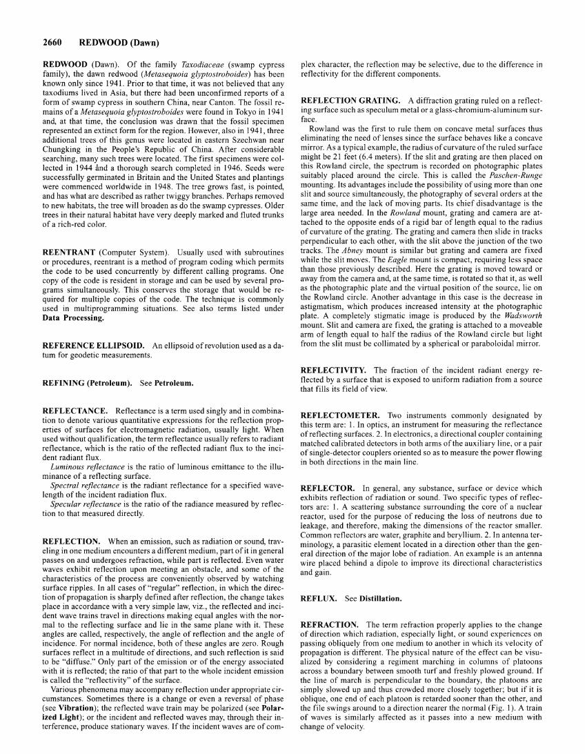
2660 REDWOOD (Dawn)
REDWOOD (Dawn). Of the family Taxodiaceae (swamp cypress family), the dawn redwood (Metasequoia glyptostroboides) has been known only since 1941. Prior to that time, it was not believed that any tax odiums lived in Asia, but there had been unconfirmed reports of a form of swamp cypress in southern China, near Canton. The fossil remains of a Metasequoia glyptostroboides were found in Tokyo in 1941 and, at that time, the conclusion was drawn that the fossil specimen represented an extinct form for the region. However, also in 1941, three additional trees of this genus were located in eastern Szechwan near Chungking in the People's Republic of China. After considerable searching, many such trees were located. The first specimens were collected in 1944 fmd a thorough search completed in 1946. Seeds were successfully germinated in Britain and the United States and plantings were commenced worldwide in 1948. The tree grows fast, is pointed, and has what are described as rather twiggy branches. Perhaps removed to new habitats, the tree will broaden as do the swamp cypresses. Older trees in their natural habitat have very deeply marked and fluted trunks of a rich-red color.
REENTRANT (Computer System). Usually used with subroutines or procedures, reentrant is a method of program coding which permits the code to be used concurrently by different calling programs. One copy of the code is resident in storage and can be used by several programs simultaneously. This conserves the storage that would be required for multiple copies of the code. The technique is commonly used in multiprogramming situations. See also terms listed under Data Processing.
REFERENCE ELLIPSOID. An ellipsoid of revolution used as adatum for geodetic measurements.
REFINING (Petroleum). See Petroleum.
REFLECTANCE. Reflectance is a term used singly and in combination to denote various quantitative expressions for the reflection properties of surfaces for electromagnetic radiation, usually light. When used without qualification, the term reflectance usually refers to radiant reflectance, which is the ratio of the reflected radiant flux to the incident radiant flux.
Luminous reflectance is the ratio of luminous emittance to the illuminance of a reflecting surface.
Spectral reflectance is the radiant reflectance for a specified wavelength of the incident radiation flux.
Specular reflectance is the ratio of the radiance measured by reflection to that measured directly.
REFLECTION. When an emission, such as radiation or sound, traveling in one medium encounters a different medium, part of it in general passes on and undergoes refraction, while part is reflected. Even water waves exhibit reflection upon meeting an obstacle, and some of the characteristics of the process are conveniently observed by watching surface ripples. In all cases of "regular" reflection, in which the direction of propagation is sharply defined after reflection, the change takes place in accordance with a very simple law, viz., the reflected and incident wave trains travel in directions making equal angles with the normal to the reflecting surface and lie in the same plane with it. These angles are called, respectively, the angle of reflection and the angle of incidence. For normal incidence, both of these angles are zero. Rough surfaces reflect in a multitude of directions, and such reflection is said to be "diffuse." Only part of the emission or of the energy associated with it is reflected; the ratio of that part to the whole incident emission is called the "reflectivity" of the surface.
Various phenomena may accompany reflection under appropriate circumstances. Sometimes there is a change or even a reversal of phase (see Vibration); the reflected wave train may be polarized (see Polarized Light); or the incident and reflected waves may, through their interference, produce stationary waves. If the incident waves are of com-
plex character, the reflection may be selective, due to the difference in reflectivity for the different components.
REFLECTION GRATING. A diffraction grating ruled on a reflecting surface such as speculum metal or a glass-chromium-aluminum surface.
Rowland was the first to rule them on concave metal surfaces thus eliminating the need of lenses since the surface behaves like a concave mirror. As a typical example, the radius of curvature of the ruled surface might be 21 feet (6.4 meters). If the slit and grating are then placed on this Rowland circle, the spectrum is recorded on photographic plates suitably placed around the circle. This is called the Paschen-Runge mounting. Its advantages include the possibility of using more than one slit and source simultaneously, the photography of several orders at the same time, and the lack of moving parts. Its chief disadvantage is the large area needed. In the Rowland mount, grating and camera are attached to the opposite ends of a rigid bar of length equal to the radius of curvature of the grating. The grating and camera then slide in tracks perpendicular to each other, with the slit above the junction of the two tracks. The Abney mount is similar but grating and camera are fixed while the slit moves. The Eagle mount is compact, requiring less space than those previously described. Here the grating is moved toward or away from the camera and, at the same time, is rotated so that it, as well as the photographic plate and the virtual position of the source, lie on the Rowland circle. Another advantage in this case is the decrease in astigmatism, which produces increased intensity at the photographic plate. A completely stigmatic image is produced by the Wadsworth mount. Slit and camera are fixed, the grating is attached to a moveable arm of length equal to half the radius of the Rowland circle but light from the slit must be collimated by a spherical or paraboloidal mirror.
REFLECTIVITY. The fraction of the incident radiant energy reflected by a surface that is exposed to uniform radiation from a source that fills its field of view.
REFLECTOMETER. Two instruments commonly designated by this term are: I. In optics, an instrument for measuring the reflectance of reflecting surfaces. 2. In electronics, a directional coupler containing matched calibrated detectors in both arms of the auxiliary line, or a pair of single-detector couplers oriented so as to measure the power flowing in both directions in the main line.
REFLECTOR. In general, any substance, surface or device which exhibits reflection of radiation or sound. Two specific types of reflectors are: I . A scattering substance surrounding the core of a nuclear reactor, used for the purpose of reducing the loss of neutrons due to leakage, and therefore, making the dimensions of the reactor smaller. Common reflectors are water, graphite and beryllium. 2. In antenna terminology, a parasitic element located in a direction other than the general direction of the major lobe of radiation. An example is an antenna wire placed behind a dipole to improve its directional characteristics and gain.
REFLUX. See Distillation.
REFRACTION. The term refraction properly applies to the change of direction which radiation, especially light, or sound experiences on passing obliquely from one medium to another in which its velocity of propagation is different. The physical nature of the effect can be visualized by considering a regiment marching in columns of platoons across a boundary between smooth turf and freshly plowed ground. If the line of march is perpendicular to the boundary, the platoons are simply slowed up and thus crowded more closely together; but if it is oblique, one end of each platoon is retarded sooner than the other, and the file swings around to a direction nearer the normal (Fig. I). A train of waves is similarly affected as it passes into a new medium with change of velocity.
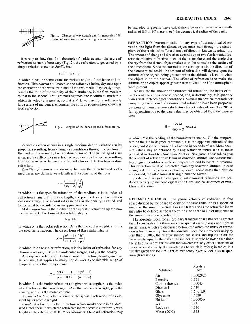
Fig. 1. Change of wavelength and (in general) of direction of wave train upon entering new medium.
It is easy to show that if i is the angle of incidence and r the angle of refraction at such a boundary (Fig. 2), the refraction is governed by a simple relation known as Snell s law:
sin i = n sin r
in which n has the same value for various angles of incidence and refraction. This constant n, known as the refractive index, depends upon the character of the wave train and of the two media. Physically it represents the ratio of the velocity of the disturbance in the first medium to that in the second. For light passing from one medium to another in which its velocity is greater, so that n < 1, we may, for a sufficiently large angle of incidence, encounter the curious phenomenon known as total reflection.
Fig. 2. Angles of incidence (i) and refraction (r).
Refraction often occurs in a single medium due to variations in its properties resulting from changes in conditions through the portion of the medium traversed by the radiation or sound. The twinkling of stars is caused by differences in refractive index in the atmosphere resulting from differences in temperature. Sound also exhibits this temperature refraction.
Specific refraction is a relationship between the refractive index of a medium at any definite wavelength and its density, of the form
r = (~: ~) (i) in which r is the specific refraction of the medium, n is its index of refraction at any definite wavelength, and p is its density. The relation does not always give a constant value of r as the density is varied, and hence must be considered as an approximation.
Molar refraction is the product of the specific refraction by the molecular weight. The form of this relationship is
R = Mr
in which R is the molar refraction, M is the molecular weight, and r is the specific refraction. The direct form of this relationship is
R=(~)(M) n2 + 2 p
in which R is the molar refraction, n is the index of refraction for any chosen wavelength, M is the molecular weight, and p is the density.
An empirical relationship between molar refraction, density, and molar volume, that applies to many liquids over a considerable range of temperatures is that of Eykiman:
R = M ( n2 - 1) = _V_:_( n_2 _-_1-'-)
p(n + 0.4) (n + 0.4)
in which R is the molar refraction at a given wavelength, n is the index of refraction at that wavelength, M is the molecular weight, p is the density, and Vis the molar volume.
Atomic refraction is the product of the specific refraction of an element by its atomic weight.
Standard refraction is the refraction which would occur in an idealized atmosphere in which the refractive index decreases uniformly with height at the rate of 39 X 10-6 per kilometer. Standard refraction may
REFRACTIVE INDEX 2661
be included in ground wave calculations by use of an effective earth radius of 8.5 X 10⁶ meters, or; the geometrical radius of the earth.
REFRACTION (Astronomical). In any type of astronomical observation, the light from the distant object must pass through the atmosphere of the earth and suffer a change of direction known as refraction. The amount of change of direction depends upon two fundamental factors: the relative refractive index of the atmosphere and the angle that the ray from the distant object makes with the normal to the surface of the atmosphere. Since the normal to the atmosphere is the direction of the astronomical zenith, the amount of refraction will depend upon the altitude of the object, being greatest when the altitude is least, or when the object is on the horizon. The effect of refraction is to make the altitude of an object appear greater than it would be if no atmosphere were present.
To calculate the amount of astronomical refraction, the index of refraction of the atmosphere is needed, and, unfortunately, this quantity varies with meteorological conditions. Various theoretical methods for computing the amount of astronomical refraction have been proposed, but none of them are very satisfactory for altitudes of less than 20°. A fair approximation to the true value may be obtained from the expression
983B R = cotan h
460 + T
in which B is the reading of the barometer in inches, T is the temperature of the air in degrees fahrenheit, h is the apparent altitude of the object, and R is the amount of refraction in seconds of arc. More accurate values may be obtained by using refraction tables such as those published in Bowditch American Practical Navigator. These tables give the amount of refraction in terms of observed altitude, and various meteorological conditions such as temperature and barometric pressure. This refraction must be subtracted from any observed altitude. In case changes due to refraction in other spherical coordinates than altitude are desired, the astronomical triangle must be solved.
Sudden and irregular changes in astronomical refraction are produced by varying meteorological conditions, and cause effects of twinkling in the stars.
REFRACTIVE INDEX. The phase velocity of radiation in free space divided by the phase velocity of the same radiation in a specified medium. Because of the Snell law (see Refraction) the refractive index may also be defined as the ratio of the sine of the angle of incidence to the sine of the angle of refraction.
The absolute index for all ordinary transparent substances is greater than 1 (see table); but there are some special cases (x-rays and light in metal films, which are discussed below) for which the index of refraction is less than unity. Since the absolute index for air exceeds unity by less than 0.0003, the relati.ve indices for solids and liquids in air are very nearly equal to their absolute indices. It should be noted that since the refractive index varies with the wavelength, any exact statement of its value must specify the wavelength to which it refers; in tables it is usually given for sodium light of frequency 5,893A. See also Dispersion (Radiation).
Substance
Air Bromine Carbon dioxide Diamond Glass Glycerine Helium Ice Rock salt Water (20°C)
Absolute Index
1.0002926 1.661 1.00045 2.419 1.5 to 1.9 1.4729 1.000036 1.31 1.516 1.333
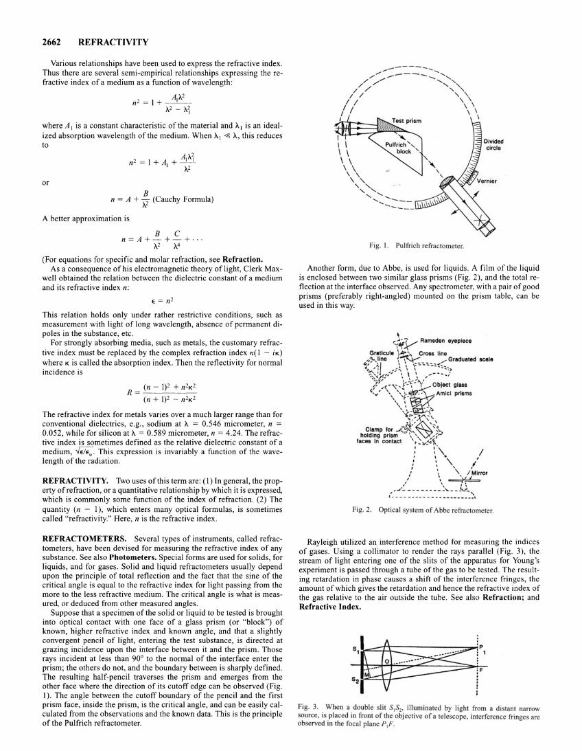
2662 REFRACTIVITY
Various relationships have been used to express the refractive index. Thus there are several semi-empirical relationships expressing the refractive index of a medium as a function of wavelength:
A A2 n2 =I+ _ _ I __
A2- A1
where A1 is a constant characteristic of the material and A1 is an idealized absorption wavelength of the medium. When A1 ~A, this reduces to
or B
n =A+ A2 (Cauchy Formula)
A better approximation is
B C n=A+-+-+ ...
A2 A_4
(For equations for specific and molar refraction, see Refraction. As a consequence of his electromagnetic theory of light, Clerk Max
well obtained the relation between the dielectric constant of a medium and its refractive index n:
E = n2
This relation holds only under rather restrictive conditions, such as measurement with light of long wavelength, absence of permanent dipoles in the substance, etc.
For strongly absorbing media, such as metals, the customary refractive index must be replaced by the complex refraction index n(l - iK) where K is called the absorption index. Then the reflectivity for normal incidence is
(n - 1)2 + n2K2 R = -'--- '------ -
(n + 1)2 - n2K2
The refractive index for metals varies over a much larger range than for conventional dielectrics, e.g., sodium at A = 0.546 micrometer, n = 0.052, while for silicon at A = 0.589 micrometer, n = 4.24. The refractive index is sometimes defined as the relative dielectric constant of a medium, -../EIE0 • This expression is invariably a function of the wavelength of the radiation.
REFRACTIVITY. Two uses of this term are: (I) In general, the property of refraction, or a quantitative relationship by which it is expressed, which is commonly some function of the index of refraction. (2) The quantity (n - 1), which enters many optical formulas, is sometimes called "refractivity." Here, n is the refractive index.
REFRACTOMETERS. Several types of instruments, called refractometers, have been devised for measuring the refractive index of any substance. See also Photometers. Special forms are used for solids, for liquids, and for gases. Solid and liquid refractometers usually depend upon the principle of total reflection and the fact that the sine of the critical angle is equal to the refractive index for light passing from the more to the less refractive medium. The critical angle is what is measured, or deduced from other measured angles.
Suppose that a specimen of the solid or liquid to be tested is brought into optical contact with one face of a glass prism (or "block") of known, higher refractive index and known angle, and that a slightly convergent pencil of light, entering the test substance, is directed at grazing incidence upon the interface between it and the prism. Those rays incident at less than 90° to the normal of the interface enter the prism; the others do not, and the boundary between is sharply defined. The resulting half-pencil traverses the prism and emerges from the other face where the diJ;ection of its cutoff edge can be observed (Fig. I). The angle between the cutoff boundary of the pencil and the first prism face, inside the prism, is the critical angle, and can be easily calculated from the observations and the known data. This is the principle of the Pulfrich refractometer.
.,.,..------, ....... ,."""' ~---..._.......__ ............. / /'/ ','
/// '"' I / ' '
I I ' ' I I \ \ I \ \ I \
l I I I \ \ \ \ \ \ \
\ ' ' ' ' ' ' ' ..... .............. ----....... ___ _
Fig. I. Pulfricb refractometer.
Another form, due to Abbe, is used for liquids. A film of the liquid is enclosed between two similar glass prisms (Fig. 2), and the total reflection at the interface observed. Any spectrometer, with a pair of good prisms (preferably right-angled) mounted on the prism table, can be used in this way.
Fig. 2. Optical sy tern of Abbe refractometer.
Rayleigh utilized an interference method for measuring the indices of gases. Using a collimator to render the rays parallel (Fig. 3 ), the stream of light entering one of the slits of the apparatus for Young's experiment is passed through a tube of the gas to be tested. The resulting retardation in phase causes a shift of the interference fringes, the amount of which gives the retardation and hence the refractive index of the gas relative to the air outside the tube. See also Refraction; and Refractive Index.
Fig. 3. When a double lit S1S2, illuminated by light from a distant narrow source, is placed in front of the objective of a telescope, interference fringe are ob erved in the focal plane P1F.
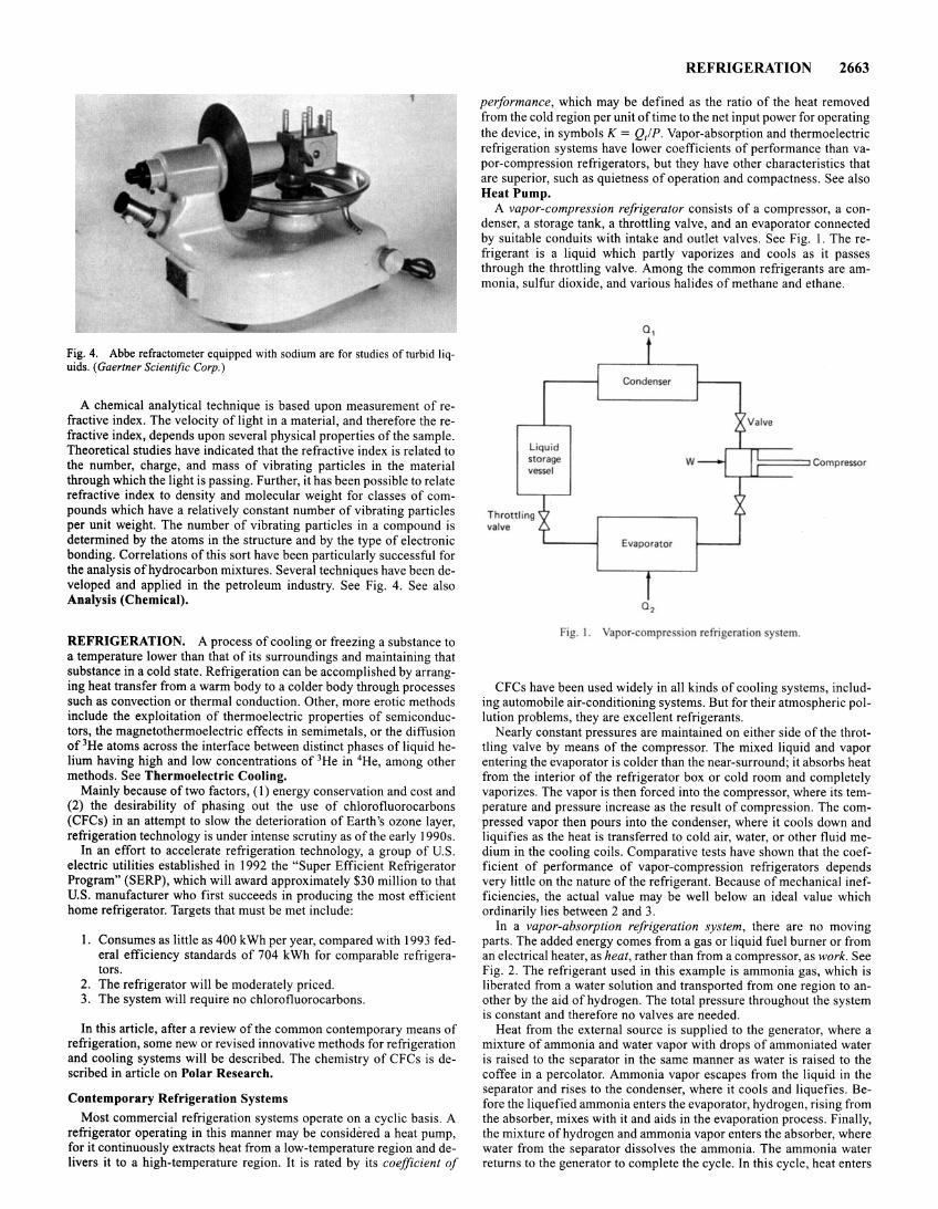
Fig. 4. Abbe refractometer equipped with sodium are for studies of turbid liquids. (Gaertner Scientific Corp.)
A chemical analytical technique is based upon measurement of refractive index. The velocity of light in a material, and therefore the refractive index, depends upon several physical properties of the sample. Theoretical studies have indicated that the refractive index is related to the number, charge, and mass of vibrating particles in the material through which the light is passing. Further, it has been possible to relate refractive index to density and molecular weight for classes of compounds which have a relatively constant number of vibrating particles per unit weight. The number of vibrating particles in a compound is determined by the atoms in the structure and by the type of electronic bonding. Correlations of this sort have been particularly successful for the analysis of hydrocarbon mixtures . Several techniques have been developed and applied in the petroleum industry. See Fig. 4. See also Analysis (Chemical).
REFRIGERATION. A process of cooling or freezing a substance to a temperature lower than that of its surroundings and maintaining that substance in a cold state. Refrigeration can be accomplished by arranging heat transfer from a warm body to a colder body through processes such as convection or thermal conduction. Other, more erotic methods include the exploitation of thermoelectric properties of semiconductors, the magnetothermoelectric effects in semimetals, or the diffusion of 3He atoms across the interface between distinct phases of liquid helium having high and low concentrations of 3He in 4He, among other methods. See Thermoelectric Cooling.
Mainly because of two factors, (1) energy conservation and cost and (2) the desirability of phasing out the use of chlorofluorocarbons (CFCs) in an attempt to slow the deterioration of Earth's ozone layer, refrigeration technology is under intense scrutiny as of the early 1990s.
In an effort to accelerate refrigeration technology, a group of U.S . electric utilities established in 1992 the "Super Efficient Refrigerator Program" (SERP), which will award approximately $30 million to that U.S. manufacturer who first succeeds in producing the most efficient home refrigerator. Targets that must be met include:
1. Consumes as little as 400 kWh per year, compared with 1993 federal efficiency standards of 704 kWh for comparable refrigerators.
2. The refrigerator will be moderately priced. 3. The system will require no chlorofluorocarbons.
In this article, after a review of the common contemporary means of refrigeration, some new or revised innovative methods for refrigeration and cooling systems will be described. The chemistry of CFCs is described in article on Polar Research.
Contemporary Refrigeration Systems
Most commercial refrigeration systems operate on a cyclic basis. A refrigerator operating in this manner may be considered a heat pump, for it continuously extracts heat from a low-temperature region and delivers it to a high-temperature region. It is rated by its coefficient of
REFRIGERATION 2663
performance, which may be defined as the ratio of the heat removed from the cold region per unit oftime to the net input power for operating the device, in symbols K = Q,IP. Vapor-absorption and thermoelectric refrigeration systems have lower coefficients of performance than vapor-compression refrigerators, but they have other characteristics that are superior, such as quietness of operation and compactness. See also Heat Pump.
A vapor-compression refrigerator consists of a compressor, a condenser, a storage tank, a throttling valve, and an evaporator connected by suitable conduits with intake and outlet valves. See Fig. 1. The refrigerant is a liquid which partly vaporizes and cools as it passes through the throttling valve. Among the common refrigerants are ammonia, sulfur dioxide, and various halides of methane and ethane.
Liquid storage vessel
Throttling valve
a,
Evaporator
w ~==:JCompressor
Fig. I . Vapor-comprc ion refrigeration y tern.
CFCs have been used widely in all kinds of cooling systems, including automobile air-conditioning systems. But for their atmospheric pollution problems, they are excellent refrigerants .
Nearly constant pressures are maintained on either side of the throttling valve by means of the compressor. The mixed liquid and vapor entering the evaporator is colder than the near-surround; it absorbs heat from the interior of the refrigerator box or cold room and completely vaporizes. The vapor is then forced into the compressor, where its temperature and pressure increase as the result of compression. The compressed vapor then pours into the condenser, where it cools down and liquifies as the heat is transferred to cold air, water, or other fluid medium in the cooling coils. Comparative tests have shown that the coefficient of performance of vapor-compression refrigerators depends very little on the nature of the refrigerant. Because of mechanical inefficiencies, the actual value may be well below an ideal value which ordinarily lies between 2 and 3.
In a vapor-absorption refrigeration system , there are no moving parts. The added energy comes from a gas or liquid fuel burner or from an electrical heater, as heat, rather than from a compressor, as work. See Fig. 2. The refrigerant used in this example is ammonia gas, which is liberated from a water solution and transported from one region to another by the aid of hydrogen. The total pressure throughout the system is constant and therefore no valves are needed.
Heat from the external source is supplied to the generator, where a mixture of ammonia and water vapor with drops of ammoniated water is raised to the separator in the same manner as water is raised to the coffee in a percolator. Ammonia vapor escapes from the liquid in the separator and rises to the condenser, where it cools and liquefies. Before the liquefied ammonia enters the evaporator, hydrogen, rising from the absorber, mixes with it and aids in the evaporation process. Finally, the mixture of hydrogen and ammonia vapor enters the absorber, where water from the separator dissolves the ammonia. The ammonia water returns to the generator to complete the cycle. In this cycle, heat enters
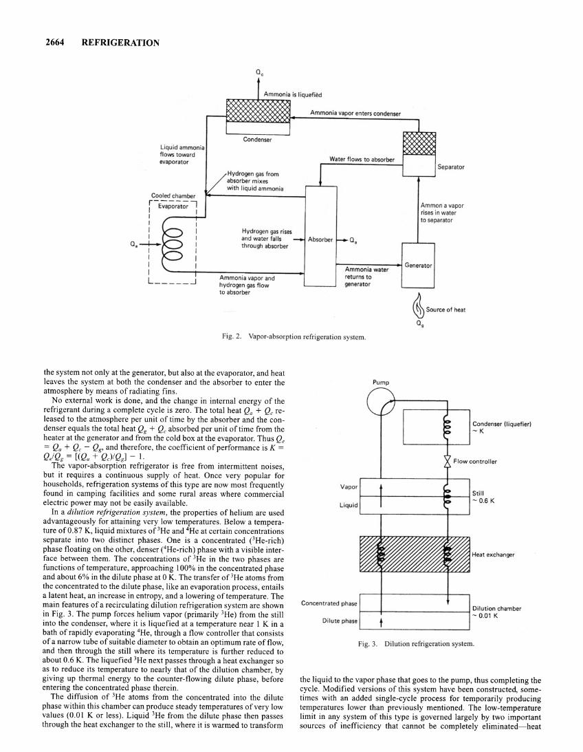
2664 REFRIGERATION
Liquid ammonia flows toward evaporator
Cooled chamber i-E~;,;;t; f I I I I I
a, --+--1 I I I L _ __ _ _ _j
Condenser
Hydrogen gas from absorber mixes with liquid ammonia
Hydrogen gas rises and water falls through absorber
Ammonia vapor and hydrogen gas flow to absorber
Ammonia vapor enters condenser
Water flows to absorber
Absorber 0,
Separator
Ammon a vapor rises in water to separator
t--:A_m_m_o_n-:-ia_w_a_t-er_., Generator
returns to generator
~ Source of heat
0 9
Fig. 2. Vapor-ab orption refrigeration system.
the system not only at the generator, but also at the evaporator, and heat leaves the system at both the condenser and the absorber to enter the atmosphere by means of radiating fins.
No external work is done, and the change in internal energy of the refrigerant during a complete cycle is zero. The total heat Qa + Qc released to the atmosphere per unit of time by the absorber and the condenser equals the total heat Qg + Qc absorbed per unit of time from the heater at the generator and from the cold box at the evaporator. Thus Qe = Qa + Qc - Qg, and therefore, the coefficient of performance is K = Q/ Qg = [(Qa + QJ!Qg] - 1.
The vapor-absorption refrigerator is free from intermittent noises, but it requires a continuous supply of heat. Once very popular for households, refrigeration systems of this type are now most frequently found in camping facilities and some rural areas where commercial electric power may not be easily available.
In a dilution refrigeration system, the properties of helium are used advantageously for attaining very low temperatures. Below a temperature of0.87 K, liquid mixtures of 3He and 4He at certain concentrations separate into two distinct phases. One is a concentrated eHe-rich) phase floating on the other, denser (4He-rich) phase with a visible interface between them. The concentrations of 3He in the two phases are functions of temperature, approaching 100% in the concentrated phase and about 6% in the dilute phase at 0 K. The transfer of 3He atoms from the concentrated to the dilute phase, like an evaporation process, entails a latent heat, an increase in entropy, and a lowering of temperature. The main features of a recirculating dilution refrigeration system are shown in Fig. 3. The pump forces helium vapor (primarily 3He) from the still into the condenser, where it is liquefied at a temperature near 1 K in a bath of rapidly evaporating 4He, through a flow controller that consists of a narrow tube of suitable diameter to obtain an optimum rate of flow, and then through the still where its temperature is further reduced to about 0.6 K. The liquefied 3He next passes through a heat exchanger so as to reduce its temperature to nearly that of the dilution chamber, by giving up thermal energy to the counter-flowing dilute phase, before entering the concentrated phase therein.
The diffusion of 3He atoms from the concentrated into the dilute phase within this chamber can produce steady temperatures of very low values (0.0 I K or less). Liquid 3He from the dilute phase then passes through the heat exchanger to the still, where it is warmed to transform
Vapor
Liquid
Concentrated phase
Dilute phase
Pump
Condenser (liquefier) -K
Flow controller
1---+--- - ---il----l Still - 0.6 K
Heat exchanger
1--- + ----------l Dilution chamber - 0.01 K
t Fig. 3. Dilution refrigeration system.
the liquid to the vapor phase that goes to the pump, thus completing the cycle. Modified versions of this system have been constructed, sometimes with an added single-cycle process for temporarily producing temperatures lower than previously mentioned. The low-temperature limit in any system of this type is governed largely by two important sources of inefficiency that cannot be completely eliminated-heat
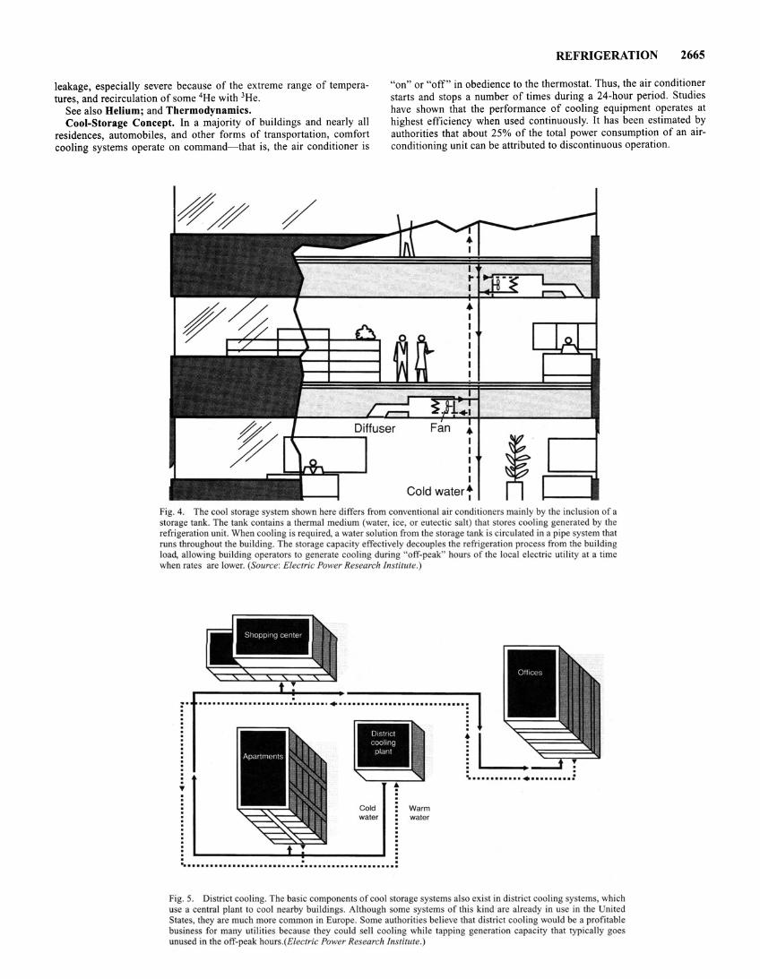
REFRIGERATION 2665
leakage, especially severe because of the extreme range of temperatures, and recirculation of some 4He with 3He.
See also Helium; and Thermodynamics. Cool-Storage Concept. In a majority of buildings and nearly all
residences, automobiles, and other forms of transportation, comfort cooling systems operate on command-that is, the air conditioner is
"on" or "off" in obedience to the thermostat. Thus, the air conditioner starts and stops a number of times during a 24-hour period. Studies have shown that the performance of cooling equipment operates at highest efficiency when used continuously. It has been estimated by authorities that about 25% of the total power consumption of an airconditioning unit can be attributed to discontinuous operation.
Diffuser • ~---------- I
I I I I
Cold water t
Fig. 4. The cool storage system shown here differs from conventional air conditioners mainly by the inclusion of a storage tank. The tank contains a thermal medium (water, ice, or eutectic salt) that stores cooling generated by the refrigeration unit. When cooling is required, a water solution from the torage tank i circulated in a pipe ystem that run throughout the building. The torage capacity effectively decouple the refrigeration process from the building load, allowing building operators to generate cooling during "off-peak" hours of the local electric utility at a time when rates are lower. (Source: Elecrric Power Research Institute.)
• Cold Warm water water
. . ~ ......................... : ..•••............... :
Fig. 5. District cooling. The basic components of cool storage systems also exist in district cooling ystems, which use a central plant to cool nearby buildings. Although some systems of this kind are al ready in use in the nited State , they are much more common in Europe. Some authoritie believe that district cooling would be a profitable busines for many utilities becau e they could sell cooling while tapping generation capacity that typically goes unused in the off-peak hours.(£/ectric Power Research lnstirute.)
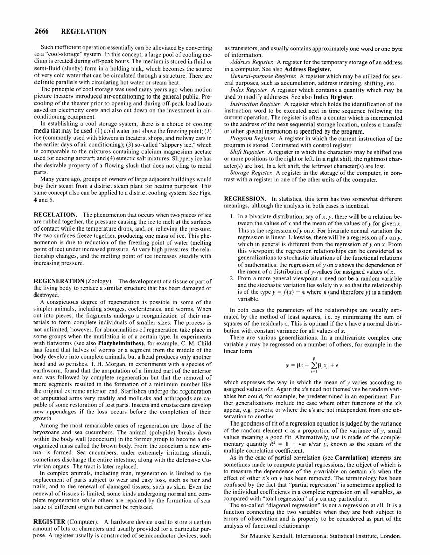
2666 REGELATION
Such inefficient operation essentially can be alleviated by converting to a "cool-storage" system. In this concept, a large pool of cooling medium is created during off-peak hours. The medium is stored in fluid or semi-fluid (slushy) form in a holding tank, which becomes the source of very cold water that can be circulated through a structure. There are definite parallels with circulating hot water or steam heat.
The principle of cool storage was used many years ago when motion picture theaters introduced air-conditioning to the general public. Precooling of the theater prior to opening and during off-peak load hours saved on electricity costs and also cut down on the investment in airconditioning equipment.
In establishing a cool storage system, there is a choice of cooling media that may be used: (I) cold water just above the freezing point; (2) ice (commonly used with blowers in theaters, shops, and railway cars in the earlier days of air conditioning); (3) so-called "slippery ice," which is comparable to the mixtures containing calcium magnesium acetate used for deicing aircraft; and ( 4) eutectic salt mixtures. Slippery ice has the desirable property of a flowing slush that does not cling to metal parts.
Many years ago, groups of owners of large adjacent buildings would buy their steam from a district steam plant for heating purposes. This same concept also can be applied to a district cooling system. See Figs. 4 and 5.
REGELATION. The phenomenon that occurs when two pieces of ice are rubbed together, the pressure causing the ice to melt at the surfaces of contact while the temperature drops, and, on relieving the pressure, the two surfaces freeze together, producing one mass of ice. This phenomenon is due to reduction of the freezing point of water (melting point of ice) under increased pressure. At very high pressures, the relationship changes, and the melting point of ice increases steadily with increasing pressure.
REGENERATION (Zoology). The development of a tissue or part of the living body to replace a similar structure that has been damaged or destroyed.
A conspicuous degree of regeneration is possible in some of the simpler animals, including sponges, coelenterates, and worms. When cut into pieces, the fragments undergo a reorganization of their materials to form complete individuals of smaller sizes. The process is not unlimited, however, for abnormalities of regeneration take place in some groups when the mutilation is of a certain type. In experiments with flatworms (see also Platyhelminthes), for example, C. M. Child has found that halves of worms or a segment from the middle of the body develop into complete animals, but a head produces only another head and so perishes. T. H. Morgan, in experiments with a species of earthworm, found that the amputation of a limited part of the anterior end was followed by complete regeneration but that the removal of more segments resulted in the formation of a minimum number like the original extreme anterior end. Starfishes undergo the regeneration of amputated arms very readily and mollusks and arthropods are capable of some restoration of lost parts. Insects and crustaceans develop new appendages if the loss occurs before the completion of their growth.
Among the most remarkable cases of regeneration are those of the bryozoans and sea cucumbers. The animal (polypide) breaks down within the body wall (zooecium) in the former group to become a disorganized mass called the brown body. From the zooecium a new animal is formed. Sea cucumbers, under extremely irritating stimuli, sometimes discharge the entire intestine, along with the defensive Cuvierian organs. The tract is later replaced.
In complex animals, including man, regeneration is limited to the replacement of parts subject to wear and easy loss, such as hair and nails, and to the renewal of damaged tissues, such as skin. Even the renewal of tissues is limited, some kinds undergoing normal and complete regeneration while others are repaired by the formation of scar issue of different origin but cannot be replaced.
REGISTER (Computer). A hardware device used to store a certain amount of bits or characters and usually provided for a particular purpose. A register usually is constructed of semiconductor devices, such
as transistors, and usually contains approximately one word or one byte of information.
Address Register. A register for the temporary storage of an address in a computer. See also Address Register.
General-purpose Register. A register which may be utilized for several purposes, such as accumulation, address indexing, shifting, etc.
Index Register. A register which contains a quantity which may be used to modify addresses. See also Index Register.
Instruction Register. A register which holds the identification of the instruction word to be executed next in time sequence following the current operation. The register is often a counter which is incremented to the address of the next sequential storage location, unless a transfer or other special instruction is specified by the program.
Program Register. A register in which the current instruction of the program is stored. Contrasted with control register.
Shift Register. A register in which the characters may be shifted one or more positions to the right or left. In a right shift, the rightmost character(s) are lost. In a left shift, the leftmost character(s) are lost.
Storage Register. A register in the storage of the computer, in contrast with a register in one of the other units of the computer.
REGRESSION. In statistics, this term has two somewhat different meanings, although the analysis in both cases is identical.
1. In a bivariate distribution, say of x, y, there will be a relation between the values of x and the mean of the values of y for given x. This is the regression of yon x. For bivariate normal variation the regression is linear. Likewise, there will be a regression ofx ony, which in general is different from the regression of yon x. From this viewpoint the regression relationships can be considered as generalizations to stochastic situations of the functional relations of mathematics: the regression of yon x shows the dependence of the mean of a distribution of y-values for assigned values of x.
2. From a more general viewpoint x need not be a random variable and the stochastic variation lies solely iny, so that the relationship is of the type y = f(x) + E where E (and therefore y) is a random variable.
In both cases the parameters of the relationships are usually estimated by the method of least squares, i.e. by minimizing the sum of squares of the residuals E. This is optimal if the E have a normal distribution with constant variance for all values of x.
There are various generalizations. In a multivariate complex one variable y may be regressed on a number of others, for example in the linear form
p
Y = Pc + L P,x, + E l=l
which expresses the way in which the mean of y varies according to assigned values of x. Again the x's need not themselves be random variables but could, for example, be predetermined in an experiment. Further generalizations include the case where other functions of the x's appear, e.g. powers; or where theE's are not independent from one observation to another.
The goodness of fit of a regression equation is judged by the variance of the random element E as a proportion of the variance of y, small values meaning a good fit. Alternatively, use is made of the complementary quantity R2 = 1 - var Elvar y, known as the square of the multiple correlation coefficient.
As in the case of partial correlation (see Correlation) attempts are sometimes made to compute partial regressions, the object of which is to measure the dependence of the y-variable on certain x's when the effect of other x's on y has been removed. The terminology has been confused by the fact that "partial regression" is sometimes applied to the individual coefficients in a complete regression on all variables, as compared with "total regression" of y on any particular x.
The so-called "diagonal regression" is not a regression at all. It is a function connecting the two variables when they are both subject to errors of observation and is properly to be considered as part of the analysis of functional relationship.
Sir Maurice Kendall, International Statistical Institute, London.
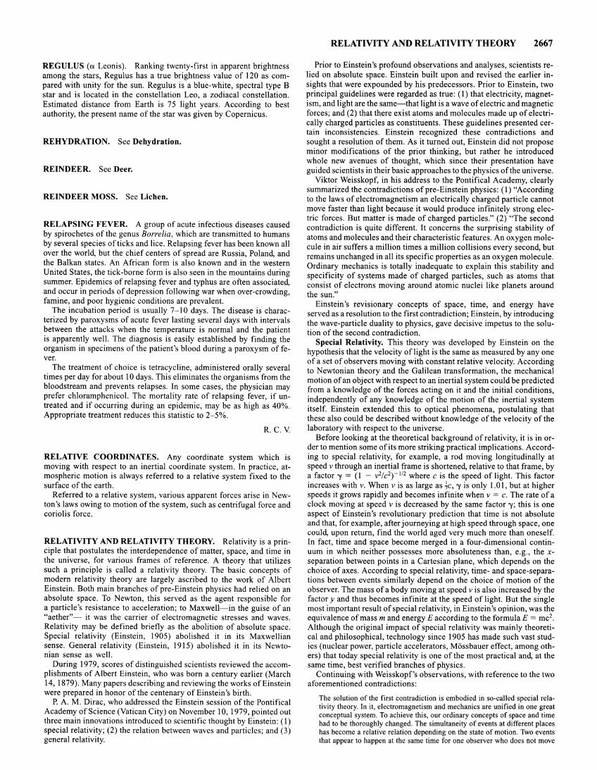
REGULUS (a Leonis). Ranking twenty-first in apparent brightness among the stars, Regulus has a true brightness value of 120 as compared with unity for the sun. Regulus is a blue-white, spectral type B star and is located in the constellation Leo, a zodiacal constellation. Estimated distance from Earth is 75 light years. According to best authority, the present name of the star was given by Copernicus.
REHYDRATION. See Dehydration.
REINDEER. See Deer.
REINDEER MOSS. See Lichen.
RELAPSING FEVER. A group of acute infectious diseases caused by spirochetes of the genus Borrelia, which are transmitted to humans by several species of ticks and lice. Relapsing fever has been known all over the world, but the chief centers of spread are Russia, Poland, and the Balkan states. An African form is also known and in the western United States, the tick-borne form is also seen in the mountains during summer. Epidemics ofrelapsing fever and typhus are often associated, and occur in periods of depression following war when over-crowding, famine, and poor hygienic conditions are prevalent.
The incubation period is usually 7-10 days. The disease is characterized by paroxysms of acute fever lasting several days with intervals between the attacks when the temperature is normal and the patient is apparently well. The diagnosis is easily established by finding the organism in specimens of the patient's blood during a paroxysm of fever.
The treatment of choice is tetracycline, administered orally several times per day for about 10 days. This eliminates the organisms from the bloodstream and prevents relapses. In some cases, the physician may prefer chloramphenicol. The mortality rate of relapsing fever, if untreated and if occurring during an epidemic, may be as high as 40%. Appropriate treatment reduces this statistic to 2-5%.
R.C.V.
RELATIVE COORDINATES. Any coordinate system which is moving with respect to an inertial coordinate system. In practice, atmospheric motion is always referred to a relative system fixed to the surface of the earth.
Referred to a relative system, various apparent forces arise in Newton's laws owing to motion of the system, such as centrifugal force and coriolis force.
RELATIVITY AND RELATIVITY THEORY. Relativity is a principle that postulates the interdependence of matter, space, and time in the universe, for various frames of reference. A theory that utilizes such a principle is called a relativity theory. The basic concepts of modern relativity theory are largely ascribed to the work of Albert Einstein. Both main branches of pre-Einstein physics had relied on an absolute space. To Newton, this served as the agent responsible for a particle's resistance to acceleration; to Maxwell-in the guise of an "aether"- it was the carrier of electromagnetic stresses and waves. Relativity may be defined briefly as the abolition of absolute space. Special relativity (Einstein, 1905) abolished it in its Maxwellian sense. General relativity (Einstein, 1915) abolished it in its Newtonian sense as well.
During 1979, scores of distinguished scientists reviewed the accomplishments of Albert Einstein, who was born a century earlier (March 14, 1879). Many papers describing and reviewing the works of Einstein were prepared in honor of the centenary of Einstein's birth.
P. A. M. Dirac, who addressed the Einstein session of the Pontifical Academy of Science (Vatican City) on November 10, 1979, pointed out three main innovations introduced to scientific thought by Einstein: (I) special relativity; (2) the relation between waves and particles; and (3) general relativity.
RELATIVITY AND RELATIVITY THEORY 2667
Prior to Einstein's profound observations and analyses, scientists relied on absolute space. Einstein built upon and revised the earlier insights that were expounded by his predecessors. Prior to Einstein, two principal guidelines were regarded as true: (1) that electricity, magnetism, and light are the same-that light is a wave of electric and magnetic forces; and (2) that there exist atoms and molecules made up of electrically charged particles as constituents. These guidelines presented certain inconsistencies. Einstein recognized these contradictions and sought a resolution of them. As it turned out, Einstein did not propose minor modifications of the prior thinking, but rather he introduced whole new avenues of thought, which since their presentation have guided scientists in their basic approaches to the physics of the universe.
Viktor Weisskopf, in his address to the Pontifical Academy, clearly summarized the contradictions of pre-Einstein physics: ( 1) "According to the laws of electromagnetism an electrically charged particle cannot move faster than light because it would produce infinitely strong electric forces. But matter is made of charged particles." (2) "The second contradiction is quite different. It concerns the surprising stability of atoms and molecules and their characteristic features. An oxygen molecule in air suffers a million times a million collisions every second, but remains unchanged in all its specific properties as an oxygen molecule. Ordinary mechanics is totally inadequate to explain this stability and specificity of systems made of charged particles, such as atoms that consist of electrons moving around atomic nuclei like planets around the sun."
Einstein's revisionary concepts of space, time, and energy have served as a resolution to the first contradiction; Einstein, by introducing the wave-particle duality to physics, gave decisive impetus to the solution of the second contradiction.
Special Relativity. This theory was developed by Einstein on the hypothesis that the velocity of light is the same as measured by any one of a set of observers moving with constant relative velocity. According to Newtonian theory and the Galilean transformation, the mechanical motion of an object with respect to an inertial system could be predicted from a knowledge of the forces acting on it and the initial conditions, independently of any knowledge of the motion of the inertial system itself. Einstein extended this to optical phenomena, postulating that these also could be described without knowledge of the velocity of the laboratory with respect to the universe.
Before looking at the theoretical background of relativity, it is in order to mention some of its more striking practical implications. According to special relativity, for example, a rod moving longitudinally at speed v through an inertial frame is shortened, relative to that frame, by a factor 'Y = (I - v2/c2)- 112 where cis the speed of light. This factor increases with v. When v is as large as ~c, 'Y is only 1.01, but at higher speeds it grows rapidly and becomes infinite when v = c. The rate of a clock moving at speed vis decreased by the same factor-y; this is one aspect of Einstein's revolutionary prediction that time is not absolute and that, for example, after journeying at high speed through space, one could, upon return, find the world aged very much more than oneself. In fact, time and space become merged in a four-dimensional continuum in which neither possesses more absoluteness than, e.g., the xseparation between points in a Cartesian plane, which depends on the choice of axes. According to special relativity, time- and space-separations between events similarly depend on the choice of motion of the observer. The mass of a body moving at speed v is also increased by the factory and thus becomes infinite at the speed of light. But the single most important result of special relativity, in Einstein's opinion, was the equivalence of mass m and energy E according to the formulaE = mc2.
Although the original impact of special relativity was mainly theoretical and philosophical, technology since 1905 has made such vast studies (nuclear power, particle accelerators, Moss bauer effect, among others) that today special relativity is one of the most practical and, at the same time, best verified branches of physics.
Continuing with Weisskopf's observations, with reference to the two aforementioned contradictions:
The solution of the first contradiction is embodied in so-called special relativity theory. In it, electromagnetism and mechanics are unified in one great conceptual system. To achieve this, our ordinary concepts of space and time had to be thoroughly changed. The simultaneity of events at different places has become a relative relation depending on the state of motion. Two events that appear to happen at the same time for one observer who does not move
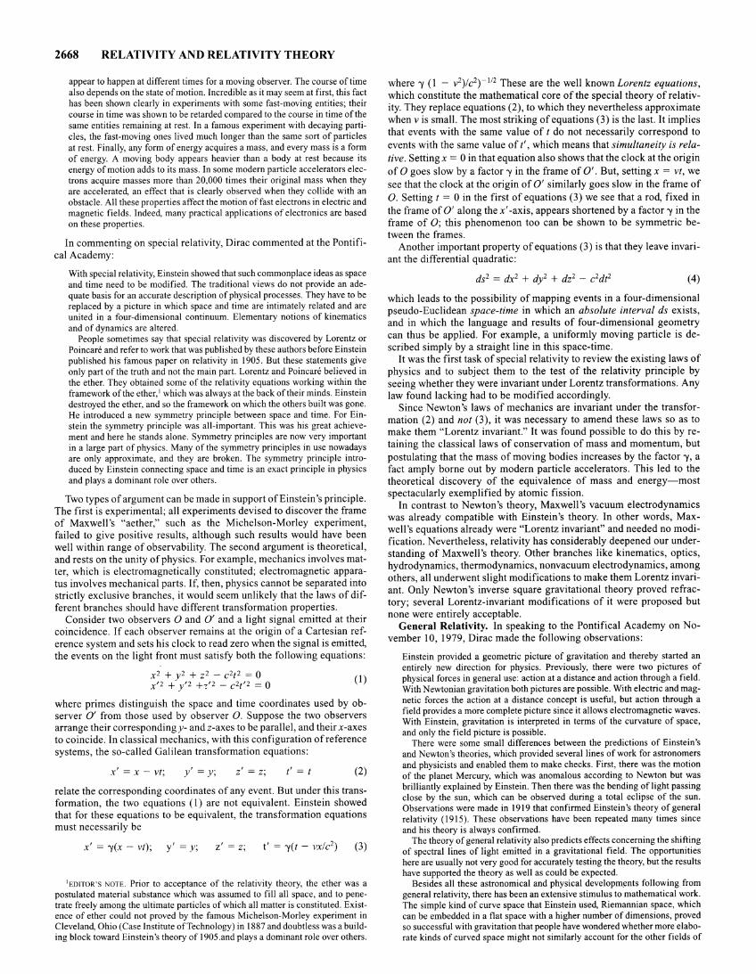
2668 RELATIVITY AND RELATIVITY THEORY
appear to happen at different times for a moving observer. The course of time also depends on the state of motion. Incredible as it may seem at first, this fact has been shown clearly in experiments with some fast-moving entities; their course in time was shown to be retarded compared to the course in time of the same entities remaining at rest. In a famous experiment with decaying particles, the fast-moving ones lived much longer than the same sort of particles at rest. Finally, any form of energy acquires a mass, and every mass is a form of energy. A moving body appears heavier than a body at rest because its energy of motion adds to its mass. In some modern particle accelerators electrons acquire masses more than 20,000 times their original mass when they are accelerated, an effect that is clearly observed when they collide with an obstacle. All these properties affect the motion of fast electrons in electric and magnetic fields. Indeed, many practical applications of electronics are based on these properties.
In commenting on special relativity, Dirac commented at the Pontifical Academy:
With special relativity, Einstein showed that such commonplace ideas as space and time need to be modified. The traditional views do not provide an adequate basis for an accurate description of physical processes. They have to be replaced by a picture in which space and time are intimately related and are united in a four-dimensional continuum. Elementary notions of kinematics and of dynamics are altered.
People sometimes say that special relativity was discovered by Lorentz or Poincare and refer to work that was published by these authors before Einstein published his famous paper on relativity in 1905. But these statements give only part of the truth and not the main part. Lorentz and Poincare believed in the ether. They obtained some of the relativity equations working within the framework of the ether, 1 which was always at the back of their minds. Einstein destroyed the ether, and so the framework on which the others built was gone. He introduced a new symmetry principle between space and time. For Einstein the symmetry principle was all-important. This was his great achievement and here he stands alone. Symmetry principles are now very important in a large part of physics. Many of the symmetry principles in use nowadays are only approximate, and they are broken. The symmetry principle introduced by Einstein connecting space and time is an exact principle in physics and plays a dominant role over others.
Two types of argument can be made in support of Einstein's principle. The first is experimental; all experiments devised to discover the frame of Maxwell's "aether," such as the Michelson-Morley experiment, failed to give positive results, although such results would have been well within range of observability. The second argument is theoretical, and rests on the unity of physics. For example, mechanics involves matter, which is electromagnetically constituted; electromagnetic apparatus involves mechanical parts. If, then, physics cannot be separated into strictly exclusive branches, it would seem unlikely that the laws of different branches should have different transformation properties.
Consider two observers 0 and 0' and a light signal emitted at their coincidence. If each observer remains at the origin of a Cartesian reference system and sets his clock to read zero when the signal is emitted, the events on the light front must satisfy both the following equations:
x2 + y2 + z2 - c2t2 = 0 x'2 + y'2 +,'2 _ c2f'2 = 0 (1)
where primes distinguish the space and time coordinates used by observer 0' from those used by observer 0. Suppose the two observers arrange their correspondingy- andz-axes to be parallel, and their x-axes to coincide. In classical mechanics, with this configuration of reference systems, the so-called Galilean transformation equations:
x' = x- vt; y' = y; z' = z; t' = t (2)
relate the corresponding coordinates of any event. But under this transformation, the two equations ( 1) are not equivalent. Einstein showed that for these equations to be equivalent, the transformation equations must necessarily be
x' = -y(x - vt); y' = y; z' = z; (3)
1EmTOR'S NOTE. Prior to acceptance of the relativity theory, the ether was a postulated material substance which was assumed to fill all space, and to penetrate freely among the ultimate particles of which all matter is constituted. Existence of ether could not proved by the famous Michelson-Morley experiment in Cleveland, Ohio (Case Institute of Technology) in 1887 and doubtless was a building block toward Einstein's theory of 1905.and plays a dominant role over others.
where -y (I - v2)/ c2) -I/2 These are the well known Lorentz equations, which constitute the mathematical core of the special theory of relativity. They replace equations (2), to which they nevertheless approximate when v is small. The most striking of equations (3) is the last. It implies that events with the same value oft do not necessarily correspond to
events with the same value oft', which means that simultaneity is relative. Setting x = 0 in that equation also shows that the clock at the origin
of 0 goes slow by a factor-y in the frame of 0'. But, setting x = vt, we
see that the clock at the origin of 0' similarly goes slow in the frame of
0. Setting t = 0 in the first of equations (3) we see that a rod, fixed in
the frame of 0' along the x' -axis, appears shortened by a factor -y in the frame of 0; this phenomenon too can be shown to be symmetric between the frames.
Another important property of equations (3) is that they leave invariant the differential quadratic:
(4)
which leads to the possibility of mapping events in a four-dimensional pseudo-Euclidean space-time in which an absolute interval ds exists, and in which the language and results of four-dimensional geometry can thus be applied. For example, a uniformly moving particle is described simply by a straight line in this space-time.
It was the first task of special relativity to review the existing laws of physics and to subject them to the test of the relativity principle by seeing whether they were invariant under Lorentz transformations. Any law found lacking had to be modified accordingly.
Since Newton's laws of mechanics are invariant under the transformation (2) and not (3), it was necessary to amend these laws so as to make them "Lorentz invariant." It was found possible to do this by retaining the classical laws of conservation of mass and momentum, but postulating that the mass of moving bodies increases by the factor -y, a fact amply borne out by modern particle accelerators. This led to the theoretical discovery of the equivalence of mass and energy-most spectacularly exemplified by atomic fission.
In contrast to Newton's theory, Maxwell's vacuum electrodynamics was already compatible with Einstein's theory. In other words, Maxwell's equations already were "Lorentz invariant" and needed no modification. Nevertheless, relativity has considerably deepened our understanding of Maxwell's theory. Other branches like kinematics, optics, hydrodynamics, thermodynamics, nonvacuum electrodynamics, among others, all underwent slight modifications to make them Lorentz invariant. Only Newton's inverse square gravitational theory proved refractory; several Lorentz-invariant modifications of it were proposed but none were entirely acceptable.
General Relativity. In speaking to the Pontifical Academy on November 10, 1979, Dirac made the following observations:
Einstein provided a geometric picture of gravitation and thereby started an entirely new direction for physics. Previously, there were two pictures of physical forces in general use: action at a distance and action through a field. With Newtonian gravitation both pictures are possible. With electric and magnetic forces the action at a distance concept is useful, but action through a field provides a more complete picture since it allows electromagnetic waves. With Einstein, gravitation is interpreted in terms of the curvature of space, and only the field picture is possible.
There were some small differences between the predictions of Einstein's and Newton's theories, which provided several lines of work for astronomers and physicists and enabled them to make checks. First, there was the motion of the planet Mercury, which was anomalous according to Newton but was brilliantly explained by Einstein. Then there was the bending of light passing close by the sun, which can be observed during a total eclipse of the sun. Observations were made in 1919 that confirmed Einstein's theory of general relativity (1915). These observations have been repeated many times since and his theory is always confirmed.
The theory of general relativity also predicts effects concerning the shifting of spectral lines of light emitted in a gravitational field. The opportunities here are usually not very good for accurately testing the theory, but the results have supported the theory as well as could be expected.
Besides all these astronomical and physical developments following from general relativity, there has been an extensive stimulus to mathematical work. The simple kind of curve space that Einstein used, Riemannian space, which can be embedded in a flat space with a higher number of dimensions, proved so successful with gravitation that people have wondered whether more elaborate kinds of curved space might not similarly account for the other fields of
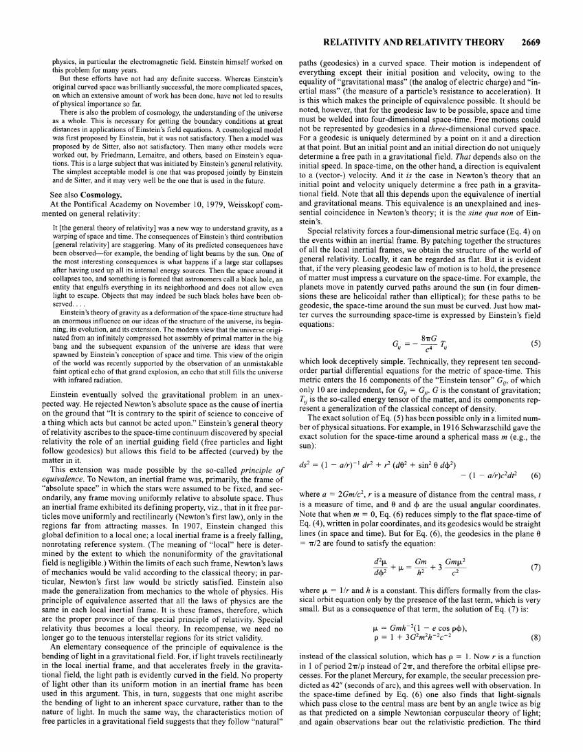
physics, in particular the electromagnetic field. Einstein himself worked on this problem for many years.
But these efforts have not had any definite success. Whereas Einstein's original curved space was brilliantly successful, the more complicated spaces, on which an extensive amount of work has been done, have not led to results of physical importance so far.
There is also the problem of cosmology, the understanding of the universe as a whole. This is necessary for getting the boundary conditions at great distances in applications of Einstein's field equations. A cosmological model was first proposed by Einstein, but it was not satisfactory. Then a model was proposed by de Sitter, also not satisfactory. Then many other models were worked out, by Friedmann, Lemaitre, and others, based on Einstein's equations. This is a large subject that was initiated by Einstein's general relativity. The simplest acceptable model is one that was proposed jointly by Einstein and de Sitter, and it may very well be the one that is used in the future.
See also Cosmology. At the Pontifical Academy on November I 0, 1979, Weisskopf com-
mented on general relativity:
It [the general theory of relativity] was a new way to understand gravity, as a warping of space and time. The consequences of Einstein's third contribution [general relativity] are staggering. Many of its predicted consequences have been observed-for example, the bending of light beams by the sun. One of the most interesting consequences is what happens if a large star collapses after having used up all its internal energy sources. Then the space around it collapses too, and something is formed that astronomers call a black hole, an entity that engulfs everything in its neighborhood and does not allow even light to escape. Objects that may indeed be such black holes have been observed ....
Einstein's theory of gravity as a deformation of the space-time structure had an enormous influence on our ideas of the structure of the universe, its beginning, its evolution, and its extension. The modern view that the universe originated from an infinitely compressed hot assembly of primal matter in the big bang and the subsequent expansion of the universe are ideas that were spawned by Einstein's conception of space and time. This view of the origin of the world was recently supported by the observation of an unmistakable faint optical echo of that grand explosion, an echo that still fills the universe with infrared radiation.
Einstein eventually solved the gravitational problem in an unexpected way. He rejected Newton's absolute space as the cause of inertia on the ground that "It is contrary to the spirit of science to conceive of a thing which acts but cannot be acted upon." Einstein's general theory of relativity ascribes to the space-time continuum discovered by special relativity the role of an inertial guiding field (free particles and light follow geodesics) but allows this field to be affected (curved) by the matter in it.
This extension was made possible by the so-called principle of equivalence. To Newton, an inertial frame was, primarily, the frame of "absolute space" in which the stars were assumed to be fixed, and secondarily, any frame moving uniformly relative to absolute space. Thus an inertial frame exhibited its defining property, viz., that in it free particles move uniformly and rectilinearly (Newton's first law), only in the regions far from attracting masses. In 1907, Einstein changed this global definition to a local one; a local inertial frame is a freely falling, nonrotating reference system. (The meaning of "local" here is determined by the extent to which the nonuniformity of the gravitational field is negligible.) Within the limits of each such frame, Newton's laws of mechanics would be valid according to the classical theory; in particular, Newton's first law would be strictly satisfied. Einstein also made the generalization from mechanics to the whole of physics. His principle of equivalence asserted that all the laws of physics are the same in each local inertial frame. It is these frames, therefore, which are the proper province of the special principle of relativity. Special relativity thus becomes a local theory. In recompense, we need no longer go to the tenuous interstellar regions for its strict validity.
An elementary consequence of the principle of equivalence is the bending oflight in a gravitational field. For, iflight travels rectilinearly in the local inertial frame, and that accelerates freely in the gravitational field, the light path is evidently curved in the field. No property of light other than its uniform motion in an inertial frame has been used in this argument. This, in turn, suggests that one might ascribe the bending of light to an inherent space curvature, rather than to the nature of light. In much the same way, the characteristics motion of free particles in a gravitational field suggests that they follow "natural"
RELATIVITY AND RELATIVITY THEORY 2669
paths (geodesics) in a curved space. Their motion is independent of everything except their initial position and velocity, owing to the equality of "gravitational mass" (the analog of electric charge) and "inertial mass" (the measure of a particle's resistance to acceleration). It is this which makes the principle of equivalence possible. It should be noted, however, that for the geodesic law to be possible, space and time must be welded into four-dimensional space-time. Free motions could not be represented by geodesics in a three-dimensional curved space. For a geodesic is uniquely determined by a point on it and a direction at that point. But an initial point and an initial direction do not uniquely determine a free path in a gravitational field. That depends also on the initial speed. In space-time, on the other hand, a direction is equivalent to a (vector-) velocity. And it is the case in Newton's theory that an initial point and velocity uniquely determine a free path in a gravitational field. Note that all this depends upon the equivalence of inertial and gravitational means. This equivalence is an unexplained and inessential coincidence in Newton's theory; it is the sine qua non of Einstein's.
Special relativity forces a four-dimensional metric surface (Eq. 4) on the events within an inertial frame. By patching together the structures of all the local inertial frames, we obtain the structure of the world of general relativity. Locally, it can be regarded as flat. But it is evident that, if the very pleasing geodesic law of motion is to hold, the presence of matter must impress a curvature on the space-time. For example, the planets move in patently curved paths around the sun (in four dimensions these are helicoidal rather than elliptical); for these paths to be geodesic, the space-time around the sun must be curved. Just how matter curves the surrounding space-time is expressed by Einstein's field equations:
81rG Gu =- -4- T;J
c (5)
which look deceptively simple. Technically, they represent ten secondorder partial differential equations for the metric of space-time. This metric enters the 16 components of the "Einstein tensor" G iJ' of which only 10 are independent, for Gi1 = GJi. G is the constant of gravitation; Tu is the so-called energy tensor of the matter, and its components represent a generalization of the classical concept of density.
The exact solution ofEq. (5) has been possible only in a limited number of physical situations. For example, in 1916 Schwarzschild gave the exact solution for the space-time around a spherical mass m (e.g., the sun):
where a = 2Gmlc2, r is a measure of distance from the central mass, t is a measure of time, and e and <1> are the usual angular coordinates. Note that when m = 0, Eq. (6) reduces simply to the flat space-time of Eq. ( 4), written in polar coordinates, and its geodesics would be straight lines (in space and time). But for Eq. (6), the geodesics in the plane 8 = 1r/2 are found to satisfy the equation:
(7)
where 1-1 = llr and h is a constant. This differs formally from the classical orbit equation only by the presence of the last term, which is very small. But as a consequence of that term, the solution ofEq. (7) is:
1-1 = Gmh-2(1 - e cos p<j>), p = 1 + 3G2m2h- 2c- 2 (8)
instead of the classical solution, which has p = 1. Now r is a function in 1 of period 21r/p instead of2TI, and therefore the orbital ellipse precesses. For the planet Mercury, for example, the secular precession predicted as 42" (seconds of arc), and this agrees well with observation. In the space-time defined by Eq. (6) one also finds that light-signals which pass close to the central mass are bent by an angle twice as big as that predicted on a simple Newtonian corpuscular theory of light; and again observations bear out the relativistic prediction. The third
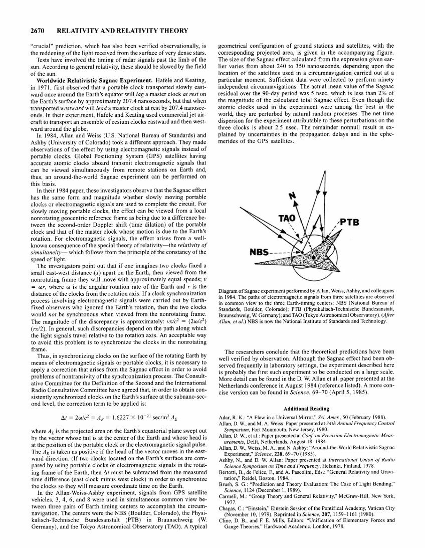
2670 RELATIVITY AND RELATIVITY THEORY
"crucial" prediction, which has also been verified observationally, is the reddening of the light received from the surface of very dense stars.
Tests have involved the timing of radar signals past the limb of the sun. According to general relativity, these should be slowed by the field of the sun.
Worldwide Relativistic Sagnac Experiment. Hafele and Keating, in 1971, first observed that a portable clock transported slowly eastward once around the Earth's equator will lag a master clock at rest on the Earth's surface by approximately 207.4 nanoseconds, but that when transported westward will lead a master clock at rest by 207.4 nanoseconds. In their experiment, Hafele and Keating used commercial jet aircraft to transport an ensemble of cesium clocks eastward and then westward around the globe.
In 1984, Allan and Weiss (U.S. National Bureau of Standards) and Ashby (University of Colorado) took a different approach. They made observations of the effect by using electromagnetic signals instead of portable clocks. Global Positioning System (GPS) satellites having accurate atomic clocks aboard transmit electromagnetic signals that can be viewed simultaneously from remote stations on Earth and, thus, an around-the-world Sagnac experiment can be performed on this basis.
In their 1984 paper, these investigators observe that the Sagnac effect has the same form and magnitude whether slowly moving portable clocks or electromagnetic signals are used to complete the circuit. For slowly moving portable clocks, the effect can be viewed from a local nonrotating geocentric reference frame as being due to a difference between the second-order Doppler shift (time dilation) of the portable clock and that of the master clock whose motion is due to the Earth's rotation. For electromagnetic signals, the effect arises from a wellknown consequence of the special theory of relativity-the relativity of simultaneity- which follows from the principle of the constancy of the speed of light.
The investigators point out that if one imagines two clocks fixed a small east-west distance (x) apart on the Earth, then viewed from the nonrotating frame they will move with approximately equal speeds; v = wr, where w is the angular rotation rate of the Earth and r is the distance of the clocks from the rotation axis. If a clock synchronization process involving electromagnetic signals were carried out by Earthfixed observers who ignored the Earth's rotation, then the two clocks would not be synchronous when viewed from the nonrotating frame. The magnitude of the discrepancy is approximately: vxlc2 = (2w/c2)
(rx/2). In general, such discrepancies depend on the path along which the light signals travel relative to the rotation axis. An acceptable way to avoid this problem is to synchronize the clocks in the nonrotating frame.
Thus, in synchronizing clocks on the surface of the rotating Earth by means of electromagnetic signals or portable clocks, it is necessary to apply a correction that arises from the Sagnac effect in order to avoid problems ofnontransivity of the synchronization process. The Consultative Committee for the Definition of the Second and the International Radio Consultative Committee have agreed that, in order to obtain consistently synchronized clocks on the Earth's surface at the subnano-second level, the correction term to be applied is:
!:J.t = 2wlc2 = AE = 1.6227 X I o-21 sec/m2 AE
where AE is the projected area on the Earth's equatorial plane swept out by the vector whose tail is at the center of the Earth and whose head is at the position of the portable clock or the electromagnetic signal pulse. The AE is taken as positive if the head of the vector moves in the eastward direction. (If two clocks located on the Earth's surface are compared by using portable clocks or electromagnetic signals in the rotating frame of the Earth, then !:J.t must be subtracted from the measured time difference (east clock minus west clock) in order to synchronize the clocks so they will measure coordinate time on the Earth.
In the Allan-Weiss-Ashby experiment, signals from GPS satellite vehicles, 3, 4, 6, and 8 were used in simultaneous common view between three pairs of Earth timing centers to accomplish the circumnavigation. The centers were the NBS (Boulder, Colorado), the Physikalisch-Technische Bundesanstalt (PTB) in Braunschweig (W. Germany), and the Tokyo Astronomical Observatory (TAO). A typical
geometrical configuration of ground stations and satellites, with the corresponding projected area, is given in the accompanying figure. The size of the Sagnac effect calculated from the expression given earlier varies from about 240 to 350 nanoseconds, depending upon the location of the satellites used in a circumnavigation carried out at a particular moment. Sufficient data were collected to perform ninety independent circumnavigations. The actual mean value of the Sagnac residual over the 90-day period was 5 nsec, which is less than 2% of the magnitude of the calculated total Sagnac effect. Even though the atomic clocks used in the experiment were among the best in the world, they are perturbed by natural random processes. The net time dispersion for the experiment attributable to these perturbations on the three clocks is about 2.5 nsec. The remainder nonnull result is explained by uncertainties in the propagation delays and in the ephemerides of the GPS satellites.
Diagram of Sagnac experiment performed by Allan, Weiss, Ashby, and colleagues in 1984. The paths of electromagnetic signals from three satellites are observed in common view to the three Earth-timing centers: NBS (National Bureau of Standards, Boulder, Colorado); PTB (Physikalisch-Technische Bundesanstalt, Braunschweig, W. Germany); and TAO (Tokyo Astronomical Observatory). (After Allan, eta/.) NBS is now the National Institute of Standards and Technology.
The researchers conclude that the theoretical predictions have been well verified by observation. Although the Sagnac effect had been observed frequently in laboratory settings, the experiment described here is probably the first such experiment to be conducted on a large scale. More detail can be found in the D. W. Allan eta!. paper presented at the Netherlands conference in August 1984 (reference listed). A more concise version can be found in Science, 69- 70 (April 5, 1985).
Additional Reading
Adar, R. K.: "A Flaw in a Universal Mirror," Sci. Amer., 50 (February 1988). Allan, D. W., and M.A. Weiss: Paper presented at 34th Annual Frequency Control
Symposium, Fort Monmouth, New Jersey, 1980. Allan, D. W., et al.: Paper presented at Conf on Precision Electromagnetic Meas
urements, Delft, Netherlands, August 18, 1984. Allan, D. W., Weiss, M.A., and N. Ashby: "Around-the-World Relativistic Sagnac
Experiment," Science, 228, 69- 70 (1985). Ashby, N., and D. W. Allan: Paper presented at International Union of Radio
Science Symposium on Time and Frequency, Helsinki, Finland, 1978. Bertotti, B., de Felice, F., and A. Pascolini, Eds.: "General Relativity and Gravi
tation," Reidel, Boston, 1984. Brush, S. G.: "Prediction and Theory Evaluation: The Case of Light Bending,"
Science, 11 24 (December I, 1989). Carmeli, M.: "Group Theory and General Relativity," McGraw-Hill, New York,
1977. Chagas, C.: "Einstein," Einstein Session of the Pontifical Academy, Vatican City
(November 10, 1979). Reprinted in Science, 207, 1159-1161 (1980). Cline, D. B., and F. E. Mills, Editors: "Unification of Elementary Forces and
Gauge Theories," Hardwood Academic, London, 1978.
Cohen, I. B.: "Newton's Discovery of Gravity," Sci. Amer., 166-179 (March 1981 ).
Davies, P., Editor: "The New Physics," Cambridge University Press, New York, 1989.
Dirac, P. A.M.: "Einstein," Einstein Session of the Pontifical Academy, Vatican City (November 10, 1979). Reprinted in Science, 207, 1161-1162 (1980).
Einstein, A.: "On the Generalized Theory of Gravitation," Sci. Amer., I (April 1950).
Ellis, P. J., and Y. C. Tang., Editor: 'Trends in Theoretical Physics," AddisonWesley, Redwood City, California, 1990.
Freedman, D. Z., and P. van Nieuwenhuizen: "The Hidden Dimensions of Spacetime," Sci. Amer., 252(3), 74-81 (1985).
French, A. P.: "Einstein: A Centenary Volume," Harvard Univ. Press, Cambridge, Massachusetts, 1979.
Geroch, R.: "Mathematical Physics," Univ. of Chicago Press, Chicago, Illinois, 1985.
Gibbons, A.: "Putting Einstein to the Test-In Space," Science, 939 (November 15, 1991).
Glick, T. F., Editor: "The Comparative Reception of Relativity," Reidel, Dordrecht, 1987.
Goldberg, S.: "Understanding Relativity," Birkhiiuser, Boston, Massachusetts, 1984.
Hafele, J. C., and R. E. Keating: Science, 177, 168 (1972). Hamilton, D. P. L.: "Laser Interferometry Gravitational Observatory," Science,
635 (Mary 3, 1991). Hawking, S. W., and W. Israel, Editors: "General Relativity," Cambridge Univ.
Press, New York, 1979. Hawking, S. W., and W. Israel, Editors: "Three Hundred Years of Gravitation,"
Cambridge University Press, New York, 1987. Hegstrom, R. A., and D. K. Kondepudi: "The Handedness of the Universe," Sci.
A mer., I 08 (January 1990). Held, A., Editor: "General Relativity and Gravitation," Plenum, New York, 1980. Pais, A.: "Subtle is the Lord: The Science and the Life of Albert Einstein," Oxford
University Press, New York, 1982. Pool, R.: "Closing in On Einstein's Special Relativity Theory," Science, 1207
(November 30, 1990). Pope John Paul II: "Einstein," Einstein Session of the Pontifical Academy, Vati
can City (November 10, 1979). Reprinted in Science, 207, 1165-1167 (1980). Pyenson, L.: "The Young Einstein: The Advent of Relativity," Hilger, Bristol,
U.K., 1985. Resnick, R.: "Basic Concepts in Relativity and Early Quantum Mechanics,"
Wiley, New York, 1972. Tipler, F. J., Editor: "Essays in General Relativity," Academic Press, New York,
1980. Weisskopf, V F.: "Einstein," Einstein Session of the Pontifical Academy, Vatican
City (November 10, 1979). Reprinted in Science, 207, I 163-1164 (1980). Will, C. M.: "Theory and Experiment in Gravitational Physics," Cambridge Uni
versity Press, New York, 1981. Will, C. M.: "General Relativity at 75: How Right Was Einstein?" Science, 770
(November 9, 1990).
RELAXATION BEHAVIOR. All phenomena where consideration of equilibrium conditions alone would give an incomplete picture and where the study of the time-dependence of the approach to equilibrium is essential for an adequate comprehension of the effect.
RELAXATION FREQUENCY. In general terms, the inverse of the relaxation time. A system is usually incapable of reacting to any periodic stimulus whose frequency is very much higher than the relaxation frequency for the effect concerned.
RELATIVE HUMIDITY. See Humidity.
RELAXATION METHOD. Originally used to calculate displacements in a structure subjected to known loads in engineering problems, it may be used to obtain eigenvalues and eigenvectors (see Eigenfunction) of algebraic or differential equations. Initial values of the eigenvalues and eigenvectors are put into the simultaneous equations of the problem. If they were the correct ones, each equation of the system would vanish; otherwise, there would be a set of residuals. The initial solutions are then varied (relaxed) until the residuals are minimized.
RELIABILITY COEFFICIENT 2671
RELAXATION PHENOMENON. Any phenomenon in which a system requires an observable length of time in order to respond to sudden changes in conditions, forces, or effects which are applied to the system.
RELAXATION TIME. In general, the time interval required for a system exposed to some discontinuous change of environment to undergo fraction (1 - e- 1), or about 63% of the total change of state which it would exhibit after an indefinitely long time.
Examples of processes exhibiting such exponential relaxation times are the change in magnetic induction resulting from a change in magnetizing force, the change in magnetic moment on removal of a crystal from a magnetic field by which its electronic spins have been aligned, and the decay of stress in a Maxwellian fluid.
RELAY. The electrical relay is a device which utilizes the variation of current in an electric circuit as a controlling factor in another. For example, a certain change of current in one circuit may cause current to begin to flow in another, by the operation of a relay connected between them. There are numerous types of electrical relays, as they have been widely used in industry, particularly in apparatus of an automatic or semi-automatic nature, or for the protection of electric power equipment, or for communication systems. Protective relays are highly specialized and developed to where they will detect any electrical abnormality, and open the circuit containing that abnormality in any required time interval. Suitable relays will detect over-current, under-current, over-voltage, under-voltage, overload, reverse current, reverse power, abnormal frequency, high temperature, grounds, and phase unbalance.
Usually the relay involves two circuits, the energizing circuit and the relay circuit (the latter variously called the trip circuit, the sounder circuit, etc.). Protective relays may close the trip circuit immediately, or after a definite time interval, or after an inverse time interval. If the trip circuit contacts are normally open, the relay is called circuit closing; if they are normally closed, the relay is called circuit opening.
The automatic protection of electric power circuits is necessary for safety and economy. Fuses and automatic circuit breakers are the device most used for opening the circuit. A relay must be used to operate the tripping circuit of the circuit breaker.
See also Circuit Breaker; and Fuse (Electric). Over a number of years, relays were extensively used in macrologic
systems (relay or ladder logic) for the sequential programming of partially or extensively automated manufacturing systems. Relay logic, although still used, was essentially displaced by the programmable logic controller (usually referred to simply as programmable controller) for a number of reasons as explained in the article on Programmable Controller.
RELIABILITY. This term is used in two different contexts. In connection with biological assay, Finney defined the reliability of an assay as the reciprocal of a function of the confidence interval (see Confidence Interval) of the estimate of potency of the stimulus.
The term is also used in factor analysis, especially in connection with the statistical analysis of psychological and educational tests. The "reliability" of a result is conceived of as that part which is due to permanent systematic effects, and therefore persists from sample to sample, as distinct from error-effects which vary from one sample to another. The term has not spread to other sciences. In a slightly more specialized sense the noun "reliability" sometimes means a reliability coefficient.
RELIABILITY COEFFICIENT. If a measured quantity y can be written in the form
y=a+b+c
where a is constant, b varies from one individual to another with variance a~, and c (representing errors of measurement, etc.) varies from
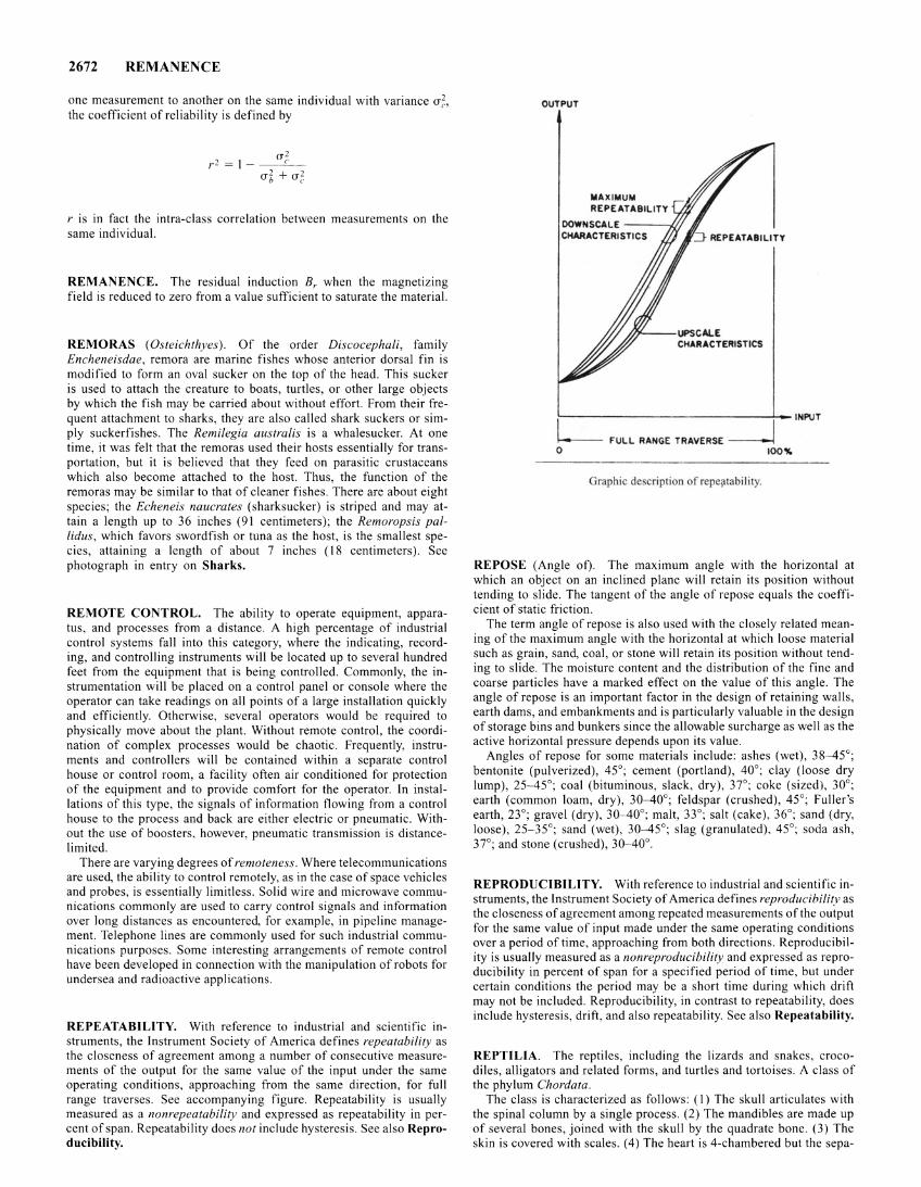
2672 REMANENCE
one measurement to another on the same individual with variance u 2
the coefficient of reliability is defined by "
u2 r2 = 1- __ c __
ul + uZ.
r is in fact the intra-class correlation between measurements on the same individual.
REMANENCE. The residual induction 8, when the magnetizing field is reduced to zero from a value sufficient to saturate the material.
REMORAS (Osteichthyes). Of the order Discocephali, family Encheneisdae, remora are marine fishes whose anterior dorsal fin is modified to form an oval sucker on the top of the head. This sucker is used to attach the creature to boats, turtles, or other large objects by which the fish may be carried about without effort. From their frequent attachment to sharks, they are also called shark suckers or simply suckerfishes. The Remilegia australis is a whalesucker. At one time, it was felt that the remoras used their hosts essentially for transportation, but it is believed that they feed on parasitic crustaceans which also become attached to the host. Thus, the function of the remoras may be similar to that of cleaner fishes. There are about eight species; the Echeneis naucrates (sharksucker) is striped and may attain a length up to 36 inches (91 centimeters); the Remoropsis pallidus, which favors swordfish or tuna as the host, is the smallest species, attaining a length of about 7 inches (18 centimeters). See photograph in entry on Sharks.
REMOTE CONTROL. The ability to operate equipment, apparatus, and processes from a distance. A high percentage of industrial control systems fall into this category, where the indicating, recording, and controlling instruments will be located up to several hundred feet from the equipment that is being controlled. Commonly, the instrumentation will be placed on a control panel or console where the operator can take readings on all points of a large installation quickly and efficiently. Otherwise, several operators would be required to physically move about the plant. Without remote control, the coordination of complex processes would be chaotic. Frequently, instruments and controllers will be contained within a separate control house or control room, a facility often air conditioned for protection of the equipment and to provide comfort for the operator. In installations of this type, the signals of information flowing from a control house to the process and back are either electric or pneumatic. Without the use of boosters, however, pneumatic transmission is distancelimited.
There are varying degrees of remoteness. Where telecommunications are used, the ability to control remotely, as in the case of space vehicles and probes, is essentially limitless. Solid wire and microwave communications commonly are used to carry control signals and information over long distances as encountered, for example, in pipeline management. Telephone lines are commonly used for such industrial communications purposes. Some interesting arrangements of remote control have been developed in connection with the manipulation of robots for undersea and radioactive applications.
REPEATABILlTY. With reference to industrial and scientific instruments, the Instrument Society of America defines repeatability as the closeness of agreement among a number of consecutive measurements of the output for the same value of the input under the same operating conditions, approaching from the same direction, for full range traverses. See accompanying figure. Repeatability is usually measured as a nonrepeatability and expressed as repeatability in percent of span. Repeatability does not include hysteresis. See also Reproducibility.
OUTPUT
MAXIMUM REPEATABILITY
OOWNSCAlE ---U/ CHARACTERISTICS .::J REPEATABiliTY
/h(._--UPSCALE CHARACTERISTICS
~--------------------------~L.- INPUT
L FULL RANGE TRAVERSE __J 0 ~~
Graphic description of repeiltabi lity.
REPOSE (Angle ot). The maximum angle with the horizontal at which an object on an inclined plane will retain its position without tending to slide. The tangent of the angle of repose equals the coefficient of static friction.
The term angle of repose is also used with the closely related meaning of the maximum angle with the horizontal at which loose material such as grain, sand, coal, or stone will retain its position without tending to slide. The moisture content and the distribution of the fine and coarse particles have a marked effect on the value of this angle. The angle of repose is an important factor in the design of retaining walls, earth dams, and embankments and is particularly valuable in the design of storage bins and bunkers since the allowable surcharge as well as the active horizontal pressure depends upon its value.
Angles of repose for some materials include: ashes (wet), 38- 45°; bentonite (pulverized), 45°; cement (portland), 40°; clay (loose dry lump), 25- 45°; coal (bituminous, slack, dry), 37°; coke (sized), 30°; earth (common loam, dry), 30-40°; feldspar (crushed), 45°; Fuller's earth, 23°; gravel (dry), 30- 40°; malt, 33°; salt (cake), 36°; sand (dry, loose), 25-35°; sand (wet), 30-45°; slag (granulated), 45°; soda ash, 37°; and stone (crushed), 30-40°.
REPRODUCIBILITY. With reference to industrial and scientific instruments, the Instrument Society of America defines reproducibilitv as the closeness of agreement among repeated measurements of the output for the same value of input made under the same operating conditions over a period of time, approaching from both directions. Reproducibility is usually measured as a nonreproducibility and expressed as reproducibility in percent of span for a specified period of time, but under certain conditions the period may be a short time during which drift may not be included. Reproducibility, in contrast to repeatability, does include hysteresis, drift, and also repeatability. See also Repeatability.
REPTILIA. The reptiles, including the lizards and snakes, crocodiles, alligators and related forms, and turtles and tortoises. A class of the phylum Chordata.
The class is characterized as follows: (I) The skull articulates with the spinal column by a single process. (2) The mandibles are made up of several bones, joined with the skull by the quadrate bone. (3) The skin is covered with scales. (4) The heart is 4-chambered but the sepa-
ration of the ventricles is incomplete. (5) The members are poikilothermal. (6) The members have extraembryonic membranes during development, a fundamental requirement of terrestrial life in the vertebrates; hence, the reptiles are grouped with the birds and mammals as Amniota.
Although the group is the lowest class of vertebrates to attain the capacity for entirely terrestrial life, many reptiles are now amphibious or aquatic. Even the aquatic species, however, come to the land to deposit their eggs.
Reptiles are economically important to a rather limited extent. The flesh of some turtles, lizards, and even snakes is used as food, and the skin of the alligator makes an excellent, if conspicuous, leather. In some regions, crocodiles have been known to kill human beings. Usually, it seems that the danger from them is very limited. Poisonous snakes also may destroy human life, but here again the danger is usually encountered only under special conditions and snake bites may be regarded as accidental.
There are a number of extinct groups, but the classification of the living groups is briefly as follows:
Order Prosauria. A single living species, the tuatara of New Zealand, makes up this order. It is a lizardlike animal with a few primitive structural characteristics, including a well-developed pineal eye. The order also bears the name Rhynchocephalia.
Order Chelonia (Testudinata). The turtles, tortoises, and related species. Characterized by the shell, consisting of an upper carapace and a lower plastron, formed of bony plates with a horny sheath.
Order Crocodilia. Large reptiles resembling lizards in form. The jaws are elongated. The thick skin is provided with bony plates. The crocodiles, alligators, garial, and related species.
Order Sauria. The lizards and snakes. In some classifications these forms are included in separate orders, and in some the lizards constitute the suborder Sauria and the snakes the suborder Serpentes of the order Squamata. The order including the lizards is also named Lacertilia. All of these animals have elongate bodies. The skin bears horny scales and in some cases bony plates.
Numerous species of reptilia are described throughout this encyclopedia.
REPULSIVE FORCES. Forces between bodies which tend to move them apart. The existence of such forces between molecules is shown by their collision diameters and similar properties; while in the case of crystals these forces, in equilibrium with forces of attraction, result in the formation of stable ionic systems.
REQUIEM SHARKS. See Sharks.
RESIDUE. Ifj(z), a function of the complex variable, has a pole at z = z0 so that it may be expanded in a Laurent series Ian(z - z0)n, then the coefficient a_ 1 is the residue of the function at the point z0• Determination of the residues of a function makes it possible to evaluate an integral in the complex plane by the Cauchy theorem (see Calculus). However, expansion in a Laurent series is not always easy so the following procedures are often used.
1. Let the function be given in the form w = f(z)lg(z) with a simple pole at z = z0• If the denominator can be factored so that g(z) = (z -z0)F(z), its residue R = f(z0)/F(z0).
2. If the denominator is not easily factored and there are n simple poles at z1, z2, z3 , ... the sum of the residues is
n
S = Lf(z,)lg'(z,) t=l
where the prime means differentiation. 3. There are simple poles at z = 0, z1, z2, ••• and the function has the
form w = f(z)lzg(z). The sum of the residues is
n
S = /(0)/g(O) + Lf(z,)lz,g'(z,) t=l
4. The function w has a pole of order katz = z0 , then its residue is
RESINS (Natural) 2673
R = __ I_ [(z- zo)kf(z) J(k -I) (k-1)! g(z) z~z0
the (k - 1 )th derivative to be evaluated at z = z0•
Modifications of these methods can be made to care for other cases.
RESILIENCE. The resilience of a body measures the extent to which energy may be stored in it by elastic deformation. The implication of the word "stored" in the above definition is that this energy may be released in the form of mechanical work when the force causing the elastic deformation is removed, and that resilience is a property of a material within its elastic limit. The "modulus of resilience" is the maximum energy storage in a unit volume of the material. In practical units, it is the inch-pounds of energy stored in a cubic inch of the material stressed to the elastic limit. The modulus of resilience is directly proportional to the square of the stress, and inversely proportional to the modulus of elasticity. It is equal to the area under the stress-stram diagram up to the elastic limit, or
2 E
in which E is the modulus of elasticity and u is the elastic limit.
RESINS (Natural). Complex compounds composed of carbon, hydrogen, and relatively small amounts of oxygen, which are secreted in various tissues of many plants. In the pine family, where resins are very common, they are secreted as oleoresins in resin canal cells, which break down finally, producing resin canals. These canals appear as longitudinal ducts in the sapwood and inner bark, connected laterally by resin canals in the compound wood rays, thus forming an extensive network. A common name given to the oleoresin in this group is pitch, the sticky juice which exudes from the plant wherever it is wounded. On exposure to the air the volatile oil in this pitch (oil of turpentine) gradually evaporates, leaving a clear hard glassy substance, the resin, which forms a protective coating over the wound.
Most resins have the same physical properties, being clear, translucent, and of a yellow or brownish color. Amber, a fossil resin, is a more or less familiar example. Resins are insoluble in water, but soluble in common organic solvents such as ether and alcohol. All resins burn with a sooty flame. Resins seem to be mainly of value to the plan in that they form protective coverings against the entrance of disease-producing organisms and also prevent excessive loss of water from the thinwalled tissues exposed in the wound.
Resins are separated into several classes. Many of the resins contain almost no volatile oil and are hard, without taste or odor. These are the varnish or hard resins. Other resins, when removed from the plant in which they are formed, and dissolved in volatile oils, form a thick semisolid mass: these are the oleoresins. In still other cases the resin occurs in combination with a gum, forming a gum resin.
Hard Resins. Several of the hard resins, used mainly for making varnishes, are called copals. Most of them come from Africa and are either found in fossil form or obtained from living plants. Other copals come from Australia, New Zealand and East Indian Islands. The plants which form them are members of the legume and pine families. The African copals are products of several species of Trachylobium, fairly large trees growing in east Africa and Madagascar. The best resin from these trees occurs in a fossil form, often deeply buried in the ground-sometimes in regions where the trees no longer grow. These resins dissolve slowly and are used in making varnishes which are very durable. A South American tree of large size, Hymenaea courbaril, also of the Leguminoseae, yields a very similar resin, which is also found in lumps in the ground around the trees, and used in varnishes.
Another copalis obtained from Agathis australis, a very large coniferous tree native in Australia and New Zealand, where it is known as the Kauri pine. Like the other copals, that from the Kauri pine is found in lumps buried in the ground. Most of these lumps are 1 or 2 inches in diameter, but some are much larger, weighing up to 100 pounds. Nearly all of this resin comes from the northern part of North Island of New
2674 RESISTANCE
Zealand. It is frequently called Kauri gum, though it is not a gum, but a true copal resin. Another group of hard resins, known as dammar resins, is obtained from many different trees growing in southern Asia and the East Indian Islands. These resins dissolve readily in alcohol, forming spirit-varnishes.
One of the commonest and most important of the hard resins is rosin, obtained by distilling the pitch, or turpentine, which is a product of several of the native pines of the southeastern United States. This rosin, also known as colophony, is a very important product of that region. Originally the turpentine was obtained by chopping a deep hollow in the base of the trunk of the tree and allowing it to fill up with the turpentine, which was then scooped out. This method was very destructive and wasteful, since much of the oleoresin, turpentine, was lost during the process. The weakened trees were easily blown down.
Now turpentine is obtained by cutting V-shaped gouges in the bark and inserting metal gutters beneath the gouges. These gutters carry the turpentine to a cup placed underneath. As soon as the cut is made, turpentine begins to flow and continues to do so for two or three days, gradually slowing as the drying turpentine allows resin to accumulate and plug the wounds. A new flow is obtained by cutting off a narrow strip of bark from the upper edge of the cut. The process is continued as long as the pitch will flow, which is usually all summer and well along into the late fall. Each tree may be turpentined for 6 to 7 successive years or even longer before it ceases to be profitable.
The crude turpentine collected in the cups and the product which has dried on the wound of the tree are removed and carried to the still. Here the turpentine, to which a little water is added, is carefully heated to drive off the oil of turpentine present, together with the water added. The distillate is condensed by passing it through a coil around which cold water is flowing, and collected in a barrel or any suitable container. The two substances, water and oil of turpentine, which make up the distillate, are immiscible and soon separate, the lighter oil of turpentine rising to the top and floating on the water, which is drawn off from the bottom. Oil of turpentine is often called spirits of turpentine, or, in the paint trade, turpentine. In medicine the word turpentine is reserved for the oleoresin which upon distillation yields oil of turpentine and rosin.
The residue remaining in the tank at the end of the distillation is skimmed to remove any impurities such as twigs, bits of bark and dirt, and run into vats to cool. Then it is put into barrels and allowed to harden, forming rosin.
Oil of turpentine is used principally as a solvent for paints and varnishes, because it mixes readily with the various substances used and also because it evaporates quickly, causing the paint or varnish to dry. It is also used in making such things as sealing wax and shoe polish. Very pure grades of turpentine (the oleoresin) are used medicinally.
Large quantities of rosin are used in sizing paper, which makes it take ink without spreading or blotting, gives it a smoother surface and makes it heavier. Rosin is also used in cheaper varnishes, in paints, and in soap making. It is furthermore used as an adulterant of the more expensive resins. Linoleum manufacturers use large amounts of rosin.
In early times, large quantities of crude turpentine were used to waterproof the rigging of the sailing vessels and to calk the seams of the hull.
Mastic is a hard resin exuding from the branches of one of the Pistachio trees, Pistacia lentiscus, native of Mediterranean Europe and southern Asia. Formerly, it was extensively used medicinally, for stomach troubles and dysentery, as well as other ailments. Now it is used in making varnishes and in lithographic work. Natives of the region in which it is found chew mastic, which has a pleasant taste.
Since turpentine is a mixture of a volatile substance, spirits of turpentine and a hard resin, it is one of the oleoresins.
0/eoresins. Canada balsam is one of the oleoresins. It is obtained from the bark of Abies balsamea, the common balsam fir of northern North America. Canada balsam, because its refractive index is so near that of glass, is much used in optical work and in preparing materials for examination with a microscope.
Little used today is Dragon's blood, an oleoresin obtained from the fruits of Daemonorops draco, a native palm of southeastern Asia and the Molucca Islands. The resins exudes from the surface of the ripening fruits. It is removed from them by boiling in water. The resin is then
moulded into balls or long sticks. It is sometimes used in making varnishes and lacquers.
True lacquer, obtained from the juice of Rhus verniciflua, a sumac tree of southeastern Asia, is another oleoresin. To obtain the juice lateral cuts are made in the bark. The exuded sap is collected not only from these cuts but from small branches which are cut off and soaked in water. The juice is cleaned of any foreign substances by straining it through hemp cloth. By slow heating, either artificial or by the sun, the juice is evaporated and stored until used. Lacquer is a poisonous substance, causing intense irritation of the skin in many people. Others seem to be immune. Lacquer is usually applied over some soft wood, commonly soft pine, the pores of which have first been filled by rubbing in a paste of rice and resin, followed by a paste of soft clay and resin. The surface is then covered with cloth and layer after layer of lacquer put over that. Each layer is allowed to dry and rubbed down very smooth before the next layer is added. Any color which is to be added is mixed with the lacquer, with each colored layer covered by a clear layer before another is put on. The final product is a thick covering composed of many thin layers of lacquers. If this is carved the edges of the carving, on careful examination, will show the fine lines separating the different layers. Lacquering is a very old industry, having been carried on in China since the sixth century.
Certain resins occur in combination with fragrant volatile oils. One of these is benzoin, obtained from Styrax benzoin by cutting notches in the bark and allowing the resin to collect in them. It is used in making perfumes, in incense, and as a source of benzoic acid, used medicinally.
Another fragrant oleoresin is storax, obtained from Liquidambar orienta/is, a medium-sized tree growing in southwestern Asia. The resin is obtained by boiling the bark and wood of young branches. It is used medicinally and also in incense.
Gum Resins. Gum resins include myrrh, which exudes from the trunk and branches of Commiphora myrrha, a tree growing in the region around the Red Sea. The lumps of resin are used medicinally, and also in making incense. Another gum resin is frankincense, obtained by cutting notches in the stem of Boswellia carterii, which grows in northeastern Africa and in Arabia. This resin is used in incense. Asafoetida is also a gum resin. See also Gums and Mucilages.
RESISTANCE. The uses of this term in physics are in accordance with its general meaning of "that which tends to oppose motion."
I. Mechanical resistance is the opposition offered by a material body to forces which tend to produce motion. This mechanical resistance may arise from friction, from stresses set up in rigid anchors, or from inertia. Whenever the power dissipated in friction is proportional to the square of the velocity, mechanical resistance may be defined as the real part of mechanical impedance, the unit of which is the mechanical ohm.
2. Acoustic resistance is defined as the real component of acoustic impedance, the commonly used unit being the acoustic ohm. Acoustic flow resistance (de acoustic resistance) is defined as the quotient of the pressure difference between the two surfaces of a sound-absorbing material by the volume current through the material.
3. Fluid resistance is the opposition offered by gases or liquids to the passage of bodies through them.
4. Electric conductors are believed to contain free electrons, the movement of which through the substance constitutes electric conduction. In this migration the moving particles evidently meet with some restraint, since heat is generated. Electrical resistance is the factor by which the square of the instantaneous conduction current must be multiplied to give the power lost by dissipation as heat or other permanent radiation of energy away from the electric circuit. (Consider the "radiation resistance" of an antenna.) The unit of electrical resistance is the ohm. The measure of the resistance of a given conductor is the electromotive force required per unit current, and is usually expressed in ohms. The resistance of a wire or other linear conductor of uniform cross section is proportional to the length I and inversely proportional to the cross section a: R = ria. The constant r is the "resistivity" of the substance, usually expressed in ohm-centimeters; and its reciprocal is the "electric conductivity." The dependence of resistivity of metals upon temperature is one of the major problems of electron physics.
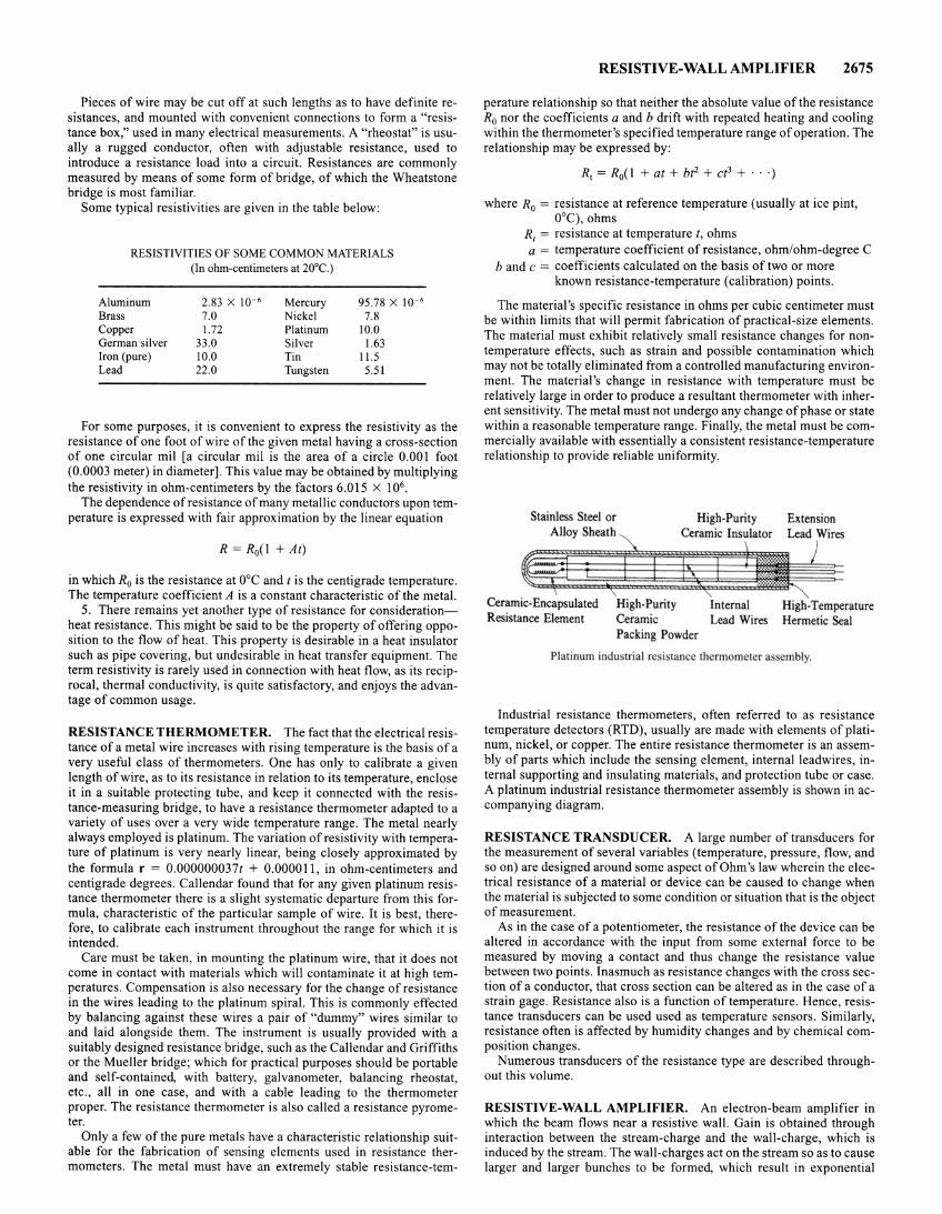
Pieces of wire may be cut off at such lengths as to have definite resistances, and mounted with convenient connections to form a "resistance box," used in many electrical measurements. A "rheostat" is usually a rugged conductor, often with adjustable resistance, used to introduce a resistance load into a circuit. Resistances are commonly measured by means of some form of bridge, of which the Wheatstone bridge is most familiar.
Some typical resistivities are given in the table below:
RESISTIVITIES OF SOME COMMON MATERlALS (In ohm-centimeters at 20°C.)
Aluminum 2.83 X 10- 6 Mercury 95 .78 X 10- 6
Brass 7.0 Nickel 7.8 Copper 1.72 Platinum 10.0 German silver 33.0 Silver 1.63 Iron (pure) 10.0 Tin 11.5 Lead 22 .0 Tungsten 5.51
For some purposes, it is convenient to express the resistivity as the resistance of one foot of wire of the given metal having a cross-section of one circular mil [a circular mil is the area of a circle 0.001 foot (0.0003 meter) in diameter]. This value may be obtained by multiplying the resistivity in ohm-centimeters by the factors 6.015 X 10⁶.
The dependence of resistance of many metallic conductors upon temperature is expressed with fair approximation by the linear equation
R = R0(1 +At)
in which R0 is the resistance at ooc and t is the centigrade temperature. The temperature coefficient A is a constant characteristic of the metal.
5. There remains yet another type of resistance for considerationheat resistance. This might be said to be the property of offering opposition to the flow of heat. This property is desirable in a heat insulator such as pipe covering, but undesirable in heat transfer equipment. The term resistivity is rarely used in connection with heat flow, as its reciprocal, thermal conductivity, is quite satisfactory, and enjoys the advantage of common usage.
RESISTANCE THERMOMETER. The fact that the electrical resistance of a metal wire increases with rising temperature is the basis of a very useful class of thermometers. One has only to calibrate a given length of wire, as to its resistance in relation to its temperature, enclose it in a suitable protecting tube, and keep it connected with the resistance-measuring bridge, to have a resistance thermometer adapted to a variety of uses over a very wide temperature range. The metal nearly always employed is platinum. The variation of resistivity with temperature of platinum is very nearly linear, being closely approximated by the formula r = 0.000000037t + 0.000011 , in ohm-centimeters and centigrade degrees. Callendar found that for any given platinum resistance thermometer there is a slight systematic departure from this formula, characteristic of the particular sample of wire. It is best, therefore, to calibrate each instrument throughout the range for which it is intended.
Care must be taken, in mounting the platinum wire, that it does not come in contact with materials which will contaminate it at high temperatures. Compensation is also necessary for the change of resistance in the wires leading to the platinum spiral. This is commonly effected by balancing against these wires a pair of "dummy" wires similar to and laid alongside them. The instrument is usually provided with a suitably designed resistance bridge, such as the Callendar and Griffiths or the Mueller bridge; which for practical purposes should be portable and self-contained, with battery, galvanometer, balancing rheostat, etc ., all in one case, and with a cable leading to the thermometer proper. The resistance thermometer is also called a resistance pyrometer.
Only a few of the pure metals have a characteristic relationship suitable for the fabrication of sensing elements used in resistance thermometers. The metal must have an extremely stable resistance-tern-
RESISTIVE-WALL AMPLIFIER 2675
perature relationship so that neither the absolute value of the resistance R0 nor the coefficients a and b drift with repeated heating and cooling within the thermometer's specified temperature range of operation. The relationship may be expressed by:
R, = R0(1 + at + bt2 + ct3 + · · ·)
where R0 = resistance at reference temperature (usually at ice pint, 0°C), ohms
R1 = resistance at temperature t, ohms a = temperature coefficient of resistance, ohm/ohm-degree C
b and c = coefficients calculated on the basis of two or more known resistance-temperature (calibration) points .
The material's specific resistance in ohms per cubic centimeter must be within limits that will permit fabrication of practical-size elements. The material must exhibit relatively small resistance changes for nontemperature effects, such as strain and possible contamination which may not be totally eliminated from a controlled manufacturing environment. The material's change in resistance with temperature must be relatively large in order to produce a resultant thermometer with inherent sensitivity. The metal must not undergo any change of phase or state within a reasonable temperature range. Finally, the metal must be commercially available with essentially a consistent resistance-temperature relationship to provide reliable uniformity.
Stainless Steel or
~IDy~h~th~ High-Purity
Ceramic Insulator
Ceramic-Encapsulated Resistance Element
High-Purity Ceramic Packing Powder
Internal Lead Wires
Extension Lead Wires
High-Temperature Hermetic Seal
Platinum indu tria l re i tance thermometer assembly.
Industrial resistance thermometers, often referred to as resistance temperature detectors (RTD), usually are made with elements of platinum, nickel, or copper. The entire resistance thermometer is an assembly of parts which include the sensing element, internal Ieadwires, internal supporting and insulating materials, and protection tube or case. A platinum industrial resistance thermometer assembly is shown in accompanying diagram.
RESISTANCE TRANSDUCER. A large number of transducers for the measurement of several variables (temperature, pressure, flow, and so on) are designed around some aspect of Ohm's law wherein the electrical resistance of a material or device can be caused to change when the material is subjected to some condition or situation that is the object of measurement.
As in the case of a potentiometer, the resistance of the device can be altered in accordance with the input from some external force to be measured by moving a contact and thus change the resistance value between two points. Inasmuch as resistance changes with the cross section of a conductor, that cross section can be altered as in the case of a strain gage. Resistance also is a function of temperature . Hence, resistance transducers can be used used as temperature sensors. Similarly, resistance often is affected by humidity changes and by chemical composition changes.
Numerous transducers of the resistance type are described throughout this volume.
RESISTIVE-WALL AMPLIFIER. An electron-beam amplifier in which the beam flows near a resistive wall. Gain is obtained through interaction between the stream-charge and the wall-charge, which is induced by the stream. The wall-charges act on the stream so as to cause larger and larger bunches to be formed, which result in exponential
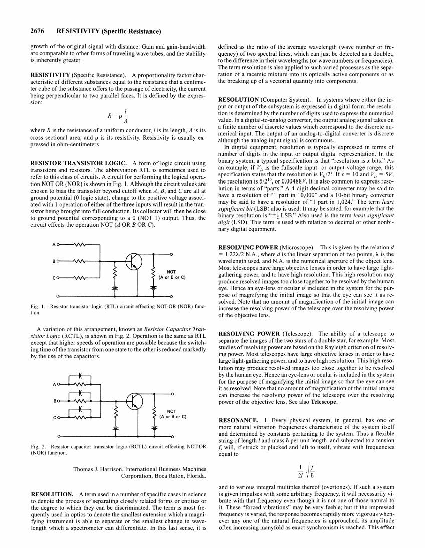
2676 RESISTIVITY (Specific Resistance)
growth of the original signal with distance. Gain and gain-bandwidth are comparable to other forms of traveling wave tubes, and the stability is inherently greater.
RESISTIVITY (Specific Resistance). A proportionality factor characteristic of different substances equal to the resistance that a centimeter cube of the substance offers to the passage of electricity, the current being perpendicular to two parallel faces. It is defined by the expresswn:
I R=p-
A
where R is the resistance of a uniform conductor, I is its length, A is its cross-sectional area, and p is its resistivity. Resistivity is usually expressed in ohm-centimeters.
RESISTOR TRANSISTOR LOGIC. A form of logic circuit using transistors and resistors. The abbreviation RTL is sometimes used to refer to this class of circuits. A circuit for performing the logical operation NOT OR (NOR) is shown in Fig. 1. Although the circuit values are chosen to bias the transistor beyond cutoff when A, B, and Care all at ground potential (0 logic state), change to the positive voltage associated with I operation of either of the three inputs will result in the transistor being brought into full conduction. Its collector will then be close to ground potential corresponding to a 0 (NOT 1) output. Thus, the circuit effects the operation NOT (A ORB OR C).
NOT (A orB or C)
Fig. I. Resistor transistor logic (RTL) circuit effecting NOT-OR (NOR) function.
A variation of this arrangement, known as Resistor Capacitor Transistor Logic (RCTL), is shown in Fig. 2. Operation is the same as RTL except that higher speeds of operation are possible because the switching time of the transistor from one state to the other is reduced markedly by the use of the capacitors.
NOT (A or B or C)
Fig. 2. Resistor capacitor transistor logic (RCTL) circuit effecting NOT-OR (NOR) function.
Thomas J. Harrison, International Business Machines Corporation, Boca Raton, Florida.
RESOLUTION. A term used in a number of specific cases in science to denote the process of separating closely related forms or entities or the degree to which they can be discriminated. The term is most frequently used in optics to denote the smallest extension which a magnifying instrument is able to separate or the smallest change in wavelength which a spectrometer can differentiate. In this last sense, it is
defined as the ratio of the average wavelength (wave number or frequency) of two spectral lines, which can just be detected as a doublet, to the difference in their wavelengths (or wave numbers or frequencies). The term resolution is also applied to such varied processes as the separation of a racemic mixture into its optically active components or as the breaking up of a vectorial quantity into components.
RESOLUTION (Computer System). In systems where either the input or output of the subsystem is expressed in digital form. the resolution is determined by the number of digits used to express the numerical value. In a digital-to-analog converter, the output analog signal takes on a finite number of discrete values which correspond to the discrete numerical input. The output of an analog-to-digital converter is discrete although the analog input signal is continuous.
In digital equipment, resolution is typically expressed in terms of number of digits in the input or output digital representation. In the binary system, a typical specification is that "resolution is x bits." As an example, if Vrs is the fullscale input- or output-voltage range, this specification states that the resolution is Vr/ZX. If x = I 0 and V1s = 5 V, the resolution is 5/2 10, or 0.00488V. It is also common to express resolution in terms of "parts." A 4-digit decimal converter may be said to have a resolution of" I part in I 0,000" and a I O-bit binary converter may be said to have a resolution of" 1 part in 1 ,024." The term least significant bit (LSB) also is used. It may be stated, for example that the binary resolution is "::+::~ LSB." Also used is the term least significant digit (LSD). This term is used with relation to decimal or other nonbinary digital equipment.
RESOLVING POWER (Microscope). This is given by the relation d = 1.22'!1./2 N.A., where dis the linear separation of two points, 'A is the wavelength used, and N.A. is the numerical aperture of the object lens. Most telescopes have large objective lenses in order to have large lightgathering power, and to have high resolution. This high resolution may produce resolved images too close together to be resolved by the human eye. Hence an eye-lens or ocular is included in the system for the purpose of magnifying the initial image so that the eye can see it as resolved. Note that no amount of magnification of the initial image can increase the resolving power of the telescope over the resolving power of the objective lens.
RESOLVING POWER (Telescope). The ability of a telescope to separate the images of the two stars of a double star, for example. Most studies of resolving power are based on the Rayleigh criterion of resolving power. Most telescopes have large objective lenses in order to have large light-gathering power, and to have high resolution. This high resolution may produce resolved images too close together to be resolved by the human eye. Hence an eye-lens or ocular is included in the system for the purpose of magnifying the initial image so that the eye can see it as resolved. Note that no amount of magnification ofthe initial image can increase the resolving power of the telescope over the resolving power of the objective lens. See also Telescope.
RESONANCE. I. Every physical system, in general, has one or more natural vibration frequencies characteristic of the system itself and determined by constants pertaining to the system. Thus a flexible string of length I and mass o per unit length, and subjected to a tension J, will, if struck or plucked and left to itself, vibrate with frequencies equal to
and to various integral multiples thereof (overtones). If such a system is given impulses with some arbitrary frequency, it will necessarily vibrate with that frequency even though it is not one of those natural to it. These "forced vibrations" may be very feeble; but if the impressed frequency is varied, the response becomes rapidly more vigorous whenever any one of the natural frequencies is approached, its amplitude often increasing manyfold as exact synchronism is reached. This effect
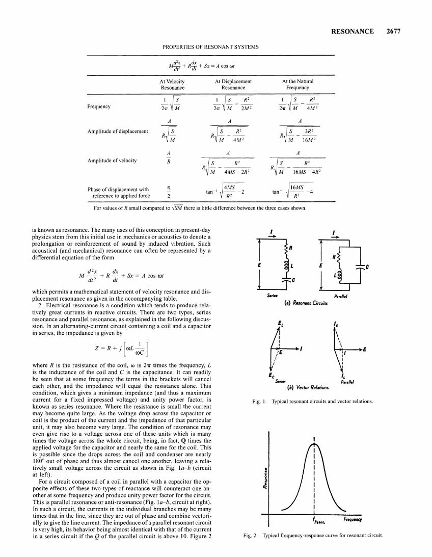
Frequency
Amplitude of displacement
Amplitude of velocity
Phase of displacement with reference to applied force
PROPERTIES OF RESONANT SYSTEMS
d'x dx lf-j]t2 + R(]J + Sx = A cos wt
At Velocity Resonance
!Js h~M
A
R
1t
2
At Displacement Resonance
I ~ S R 2
271" M 2M 2
A
R~~-~ M 4M 2
A
~ S R' R M- 4MS -2R2
~ tan-• 2
At the Natural Frequency
I ~ S R 2
271" M 4M 2
A
~ S 3R 2
R M - 16M 2
A
~ S R 2
R M - 16MS -4R2
tan_ 1 ~16MS _ 4 R'
For values of R small compared to ..fSM there is little difference between the three cases shown.
is known as resonance. The many uses of this conception in present-day physics stem from this initial use in mechanics or acoustics to denote a prolongation or reinforcement of sound by induced vibration. Such acoustical (and mechanical) resonance can often be represented by a differential equation of the form
d 2x dx M - + R - + Sx· = A cos wt
dt 2 dt
which permits a mathematical statement of velocity resonance and displacement resonance as given in the accompanying table.
2. Electrical resonance is a condition which tends to produce relatively great currents in reactive circuits. There are two types, series resonance and parallel resonance, as explained in the following discussion. In an alternating-current circuit containing a coil and a capacitor in series, the impedance is given by
S.ties
(•) Resonant Orcuits
Ec Series
(b) Vector Relations
RESONANCE
c
P.rallel
where R is the resistance of the coil, w is 2TI times the frequency, L is the inductance of the coil and C is the capacitance. It can readily be seen that at some frequency the terms in the brackets will cancel each other, and the impedance will equal the resistance alone. This condition, which gives a minimum impedance (and thus a maximum current for a fixed impressed voltage) and unity power factor, is known as series resonance. Where the resistance is small the current may become quite large. As the voltage drop across the capacitor or coil is the product of the current and the impedance of that particular unit, it may also become very large. The condition of resonance may even give rise to a voltage across one of these units which is many times the voltage across the whole circuit, being, in fact, Q times the applied voltage for the capacitor and nearly the same for the coil. This is possible since the drops across the coil and condenser are nearly 180° out of phase and thus almost cancel one another, leaving a relatively small voltage across the circuit as shown in Fig. la-b (circuit at left).
Fig. I. Typical resonant circuits and vector relations.
For a circuit composed of a coil in parallel with a capacitor the opposite effects of these two types of reactance will counteract one another at some frequency and produce unity power factor for the circuit. This is parallel resonance or anti-resonance (Fig. la-b, circuit at right). In such a circuit, the currents in the individual branches may be many times that in the line, since they are out of phase and combine vectorially to give the line current. The impedance of a parallel resonant circuit is very high, its behavior being almost identical with that of the current in a series circuit if the Q of the parallel circuit is above I 0. Figure 2 Fig. 2. Typical frequency-response curve for resonant circuit.
2677
2678 RESONANCE RADIATION
shows a typical frequency-response curve for resonant circuits, the ordinates being current for a series and impedance for a parallel resonant circuit. In series resonance, the condition for resonance is given exactly by the following expression which is also approximately true for parallel resonance if the Q is high:
wL = 1/wC
From this equation the resonant frequency is found to be
I f=-=
27r.JLC
Both types of resonance are widely used in communication circuits to select certain frequencies in preference to others. An example is the tuning circuit of the radio receiver.
3. Resonance phenomena are exhibited by all systems in motion, including molecular, atomic and electronic systems. The approach of quantum mechanics clarifies the behavior of such systems.
4. Another resonance phenomenon involving electrons or atomic nuclei is magnetic resonance.
Nonlinear Resonance. Provided the dissipation of the system is low, the curve of the response (e.g., rms value) to a driving force, of a double energy-storage, passive system containing at least one nonlinear energy storage element may be double-valued over a certain range, when plotted against the independent variable of driving force, or frequency, or one of the system parameters. Such a system is said to be in nonlinear resonance, if the operating point is on the upper leg of this double-valued response curve, and if the lowest-frequency component of theresponse is of the same frequency as the fundamental frequency of the driving force. If the circuit parameters or the excitation or both preclude the existence of a double-valued response, the system is said to be in nonlinear resonance if the operating point is in that range of the curve of response (e.g., root-mean-square value) versus driving force, in which the slope of the curve is greater than the slope in the vicinity of the origin.
RESONANCE RADIATION. A process ofre-emission of radiation by gases and vapors. The process involves excitation, by incident photons, of atoms to higher energy levels, from which they may return to the ground state, or to other states. Therefore the radiation emitted, while characteristic of the particular atom, is not necessarily of the same frequency as that absorbed. Resonance radiation appears to be a species of fluorescence, except that it may take place with no change in frequency. For example, Wood found that sodium vapor, upon absorption ofD-light (16,973 cm- 1), re-emitted the same frequency and therefore the name resonance radiation was adopted. But when Strutt excited sodium vapor by light of wave number 30,273 cm- 1 (second line of the principal sodium series), the emitted radiation was D-light (16,973 cm- 1).
RESONATOR. 1. A device used to utilize or exhibit the effects of resonance. 2. A group of electrons which absorbs electromagnetic radiation of certain frequencies.
RESORPTION. The absorption, or less commonly, the adsorption by a body or system of material previously released from absorption or adsorption by that same body or system.
RESPIRATION (Plants). Plant cells, like all living cells, require energy to maintain the organization of materials and activities which we associate with life. In plant cells, as in animal cells, this energy is provided by the oxidation of foods, commonly carbohydrates, in the process known as respiration. This oxidation is a sequence of enzyme-controlled reactions, in which the energy of the food is released a little at a time. The net result of the breakdown of a carbohydrate, commonly glucose, is the production of carbon dioxide and water, and the utilization of oxygen. The following equation expresses the overall result:
Thus oxygen is absorbed from the atmosphere and carbon dioxide is released.
The net results of this process are the opposite of those in photosynthesis, in which carbon dioxide is used and oxygen is produced. When green parts of plants are exposed to light, ordinarily photosynthesis proceeds much faster than respiration, so that respiration cannot be detected by the gaseous exchanges. In the dark, however, the green tissues as well as those lacking chlorophyll demonstrate the gas exchange characteristic of respiration.
Sometimes other foods, such as proteins, fats, or organic acids, may be oxidized in plant cells. In such cases the respiratory quotient (R.Q.) or respiratory ratio (ratio of amount of C02 released to amount of 0 2 used) is not 1, as it is when carbohydrates are oxidized. Proteins and fats contain relatively less oxygen than do the carbohydrates, so more oxygen is required to bring about their complete oxidation, and the R.Q. is less than I. When certain of the organic acids are respired, the R.Q. is greater than I .
The sequence of chemical reactions in respiration results in a stepwise breakdown of the carbohydrate molecule. Phosphate groups are incorporated as a part of the sugar molecule, and are exceedingly important in the energy relationships of the cell. In certain types of phosphate-containing organic compounds, the phosphate is attached through "energy-rich" bonds. When these bonds are broken, the energy thus released may drive a chemical reaction or may perform useful work within the cell. Several of the steps in the respiratory process produce these energy-rich compounds. This represents a means of transferring energy within the cell, from respiration to other chemical processes or to any site where energy is required.
The separate reactions in the sequence of respiration are controlled by enzymes. A large number of enzymes are required for the whole process. A number of these depend for their activity upon coenzymes which are vitamins of the B complex, or derivatives of these compounds. For example, thiamine (vitamin B1) serves as a coenzyme in the release of carbon dioxide.
The energy released in respiration may be used in a variety of ways. Protoplasm must be made continually, especially where there is rapid growth. The manufacture of protoplasm requires energy. The synthesis of many other compounds within the cell also requires energy. The accumulation of mineral ions by plant cells, the "pumping" of water by root pressure, and the maintenance of the semipermeability of the plasma membrane all require some of the respiratory energy. Unfortunately for the plant, the energy transfers are not completely efficient, and some of the energy is lost as heat. The release of heat is frequently demonstrated by placing germinating seeds in a thermos bottle and noting the increase in temperature of the seeds with a thermometer.
The foregoing discussion refers primarily to aerobic respiration, or respiration at the expense of atmospheric oxygen. Anaerobic respiration also may occur in plant cells. A familiar example is the fermentation which occurs when yeast cells act upon a sugar solution:
The sugar is partially oxidized, releasing carbon dioxide and alcohol and liberating some of the energy stored in the sugar. The process can occur in the absence of oxygen. Sometimes other products, such as acetic acid or lactic acid, result from similar processes. Some of the initial enzymes and chemical reactions in these processes are the same as those in aerobic respiration. In most plant cells aerobic respiration occurs in preference to anaerobic respiration if oxygen is available. This is advantageous to the plant because the aerobic reaction releases considerably more of the available energy of the food being oxidized.
RESPIRATORY SYSTEM. The assemblage of organs by which air or water is brought into contact with tissues which can absorb part of its contents of oxygen.
Many animals absorb oxygen through the surface of the body. This is particularly true of small and simple forms, but the skin of the earth-
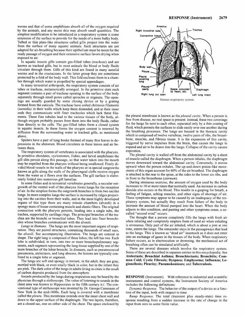
worms and that of some amphibians absorb all of the oxygen required by the animals, and any moist skin may absorb small quantities . The simplest modification to be introduced as a respiratory system is some extension of the surface to provide for the needs of a more bulky body. Tufted or thin plate-like structures called gills project into the water from the surface of many aquatic animals. Such structures are not adapted for air-breathing because their epithelium must be moist for the ready passage of oxygen and their extensive surface favors drying when exposed to air.
In aquatic insects gills contain gas-filled tubes (tracheae) and are known as tracheal gills, but in most animals the blood or body fluids circulate through them. Gills of this kind are found in many annelid worms and in the crustaceans. In the latter group they are sometimes protected by a fold of the body wall. This fold encloses them in a chamber through which water is propelled by special appendages.
In many terrestrial arthropods, the respiratory system consists of air tubes or tracheae, metamerically arranged. In the primitive state each segment contains a pair of tracheae opening to the surface of the body separately through small pores called spiracles or stigmata. The openings are usually guarded by some closing device or by a grating formed from the cuticula. The tracheae have coiled chitinous filaments (taenidia) in their walls which keep them distended, and at their inner ends they communicate with finer tracheoles which lack these filaments . These fine tubules lead to the various tissues of the body, although oxygen probably passes from them into the body fluids, rather than directly to the cells. The gas-filled tubes form a closed system i~ aq~atic insects. In these forms the oxygen content is renewed by dtffuswn from the surrounding water in tracheal gills, as mentioned above .
Spiders have a pair of lung books formed of many thin leaves in depressions in the abdomen. Blood circulates in these leaves and air between them.
The respiratory system of vertebrates is associated with the pharynx. In primitive chordates, cyclostomes, fishes , and larval amphibians the gill slits persist along this passage, so that water taken into the mouth may be expelled from the pharynx without being swallowed. Finely divided blood vessels in the walls of the pharynx or in special outgrowths known as gills along the walls of the pharyngeal clefts receive oxygen from the water as it flows over the surfaces. The gill surface is elaborately folded into numerous gill lamellae.
In some fishes and in terrestrial vertebrates generally, a saccular outgrowth of the ventral wall of the pharynx forms lungs for the reception of air. In the simplest forms the outgrowth branches to form two saclike lungs . In more complex lungs the surface is increased by ridges projecting into the cavities from their walls, and in the most highly developed organs of this type there are many minute chambers (alveoli) in a spongy mass of tissue containing muscle and elastic fibers. The original connection with the pharynx persists, leading into a single tube, the trachea, supported by cartilage rings . The principal branches of the trachea are the bronchi or bronchial tubes. They lead into finer bronchioles whose branches communicate with the alveoli .
Lungs in Humans. The lungs are the most important organs of respiration. They are paired structures, containing thousands of small sacs, the alveoli. See accompanying illustration. The lungs are conical in shape. The right lung is composed of three lobes; the left has two. Each lobe is subdivided, in turn, into two or more bronchopulmonary segments, each segment representing the lung tissue supplied by one of the main branches of the lobar bronchi . In diseases, such as pneumococcal pneumonia, atelectasis, and lung abscess, the lesions are typically confined to a single lobe or segment.
The lun~s are soft and spongy in texture; in the adult, they are gray, mottled wtth black, or even totally black in color, but in the infant they are pink. The dark color of the lungs in adults living in cities is the result of carbon deposits produced from the atmosphere.
Sounds produced by the lungs during respiration may be heard by the physician through a stethoscope. The value of listening to sounds in the chest area was known to Hippocrates in the fifth century B.C. The conventional type of stethoscope was invented by Dr. George Cammann of New York in the mid-1800s. Each lung is covered with a membrane called the pleura. This membrane extends over the inner chest wall and down to the upper surface of the diaphragm. The two layers, therefore, are a closed sac, one on either side of the chest. The space enclosed by
RESPONSE (Instrument)
Space tupled\ Diaphragm by heart, •te.
Left lung Intact
Human respiratory system.
2679
the pleural membrane is known as the pleural cavity. When a person is free from disease, no real space is present. Instead, these two coverings for the lungs lie next to each other, separated only by a thin coating of fluid, which permits the surfaces to slide easily over one another during the breathing processes. The lungs are housed in the thoracic cavity which is composed of twelve vertebrae, twelve pairs of ribs, the breastbone, muscles, and fibrous tissue. It is the expansion of this cavity, triggered by nerve impulses from the brain, that causes the lungs to expand and air to be drawn into the lungs . Collapse of the cavity causes expiration.
The pleural cavity is walled off from the abdominal cavity by a sheet of muscle called the diaphragm . When a person inhales, the diaphragm moves downward toward the abdominal cavity. Conversely, it moves upward when the person exhales. The up-and-down piston-like movements of this organ account for 60% of the air breathed. The diaphragm is attached in the rear to the spine, at the sides to the lower six ribs, and in front to the breastbone (sternum) .
During strenuous exercise, the amount of oxygen used by the body increases to I 0 or more times that normally used. An increase in carbon dioxide also occurs in the blood. This results in a gasping for breath, a feeling of fatigue, aching muscles, and other signs of shortage of air. These symptoms may appear to be caused by an inadequacy of the respiratory system, but actually they result from failure of the body to increase the amount of blood pumped into the heart. When the body adjusts to this condition, and panting and other symptoms cease, a socalled "second wind" occurs.
The thought that a person completely fills the lungs with fresh air when inhaling and completely empties them of used air when exhaling ts erroneous. Only part of the air inhaled, which is about a pint at one time, enters the lungs . The remainder stays in the passageways that lead to the lungs. This is known as "dead air" inasmuch as it does not enter into an exchange of gases in the tissues of the body. When respiratory failure occurs, as in electrocution or drowning, the mechanical act of breathing often can be simulated artificially.
There are several diseases which involve the respiratory system. Some ofthese are described in separate entries in this encyclopedia. See Atelectasis; Bronchial Asthma; Bronchiectasis; Bronchitis; Common Cold; Cystic Fibrosis; Dyspnea; Emphysema; Influenza; Legionellosis; Pleurisy; Pneumokonioses; and Tuberculosis.
RESPONSE (Instrument) . With reference to industrial and scientific instruments and control systems, the Instrument Society of America includes the following definitions:
Dynamic Response. The behavior of the output of a device as a function of the input, both with respect to time.
Ramp Response. The total (transient plus steady-state) time response resulting from a sudden increase in the rate of change in the input from zero to some finite value.
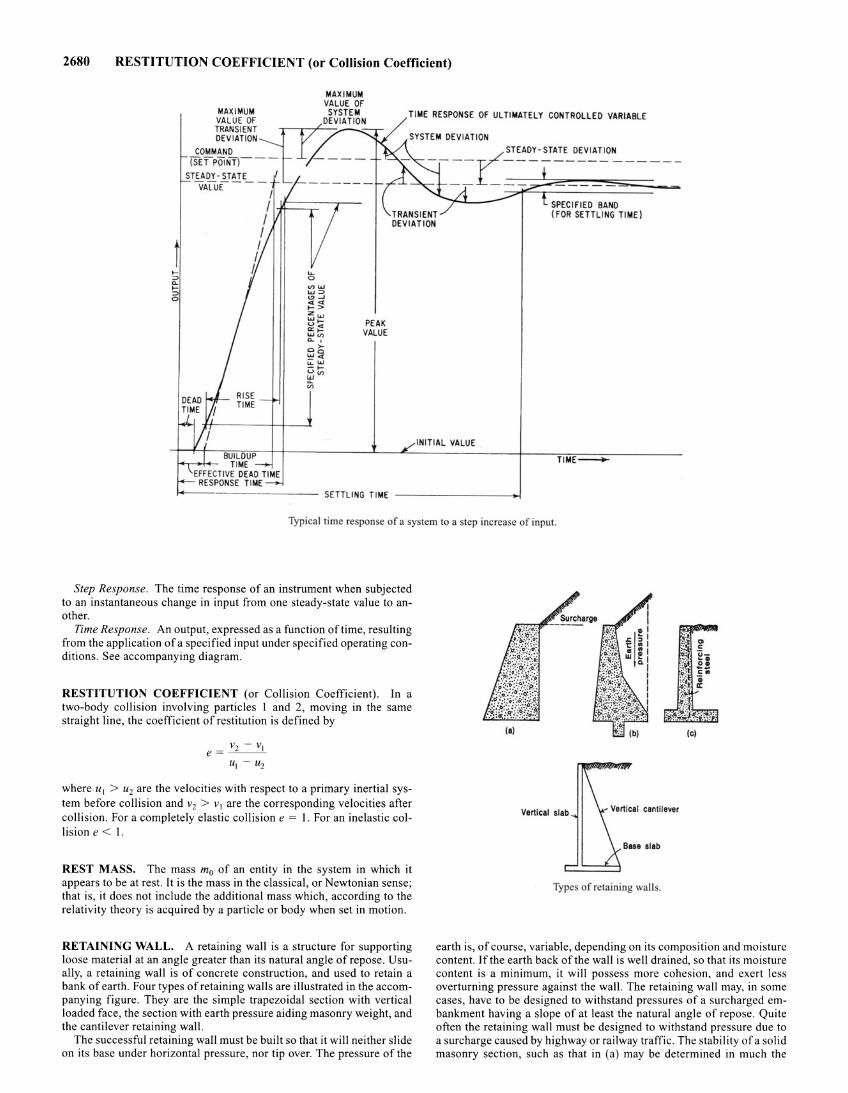
2680 RESTITUTION COEFFICIENT (or Collision Coefficient)
MAXIMUM VALUE Of
MAXIMUM SYSTEM VALUE Of ~DEVIAT ION
TIME RESPONSE OF ULTIMATELY CONTROLLED VARIABLE
TRANSIENT DEVIATION SYSTEM DEVIATION
COMMAND (SET POiNfl___ - -- -
STEADY- STATE VALuE- - -, - --- --
1 $=:=;::---r-1 I I I
I.
PEAK VALUE
r STEADY - STATE DEVIATION
- --- ----------------- - - ---- -
SPECIFIED BAND (fOR SETTLING TIME)
INITIAL VALUE
Typical time re ponse of a system to a tep increase of input.
Step Response. The time response of an instrument when subjected to an instantaneous change in input from one steady-state value to another.
Time Response. An output, expressed as a function of time, resulting from the application of a specified input under specified operating conditions. See accompanying diagram.
RESTITUTION COEFFICIENT (or Collision Coefficient). In a two-body collision involving particles I and 2, moving in the same straight line, the coefficient of restitution is defined by
where u1 > u2 are the velocities with respect to a primary inertial system before collision and v2 > v1 are the corresponding velocities after collision. For a completely elastic collision e = 1. For an inelastic collision e < I.
REST MASS. The mass m0 of an entity in the system in which it appears to be at rest. It is the mass in the classical, or Newtonian sense; that is, it does not include the additional mass which, according to the relativity theory is acquired by a particle or body when set in motion.
RETAINING WALL. A retaining wall is a structure for supporting loose material at an angle greater than its natural angle of repose. Usually, a retaining wall is of concrete construction, and used to retain a bank of earth. Four types of retaining walls are illustrated in the accompanying figure. They are the simple trapezoidal section with vertical loaded face, the section with earth pressure aiding masonry weight, and the cantilever retaining wall.
The successful retaining wall must be built so that it will neither slide on its base under horizontal pressure, nor tip over. The pressure of the
(C)
Type of retaining walls.
earth is, of course, variable, depending on its composition and moisture content. If the earth back of the wall is well drained, so that its moisture content is a minimum, it will possess more cohesion, and exert less overturning pressure against the wall. The retaining wall may, in some cases, have to be designed to withstand pressures of a surcharged embankment having a slope of at least the natural angle of repose. Quite often the retaining wall must be designed to withstand pressure due to a surcharge caused by highway or railway traffic. The stability of a solid masonry section, such as that in (a) may be determined in much the
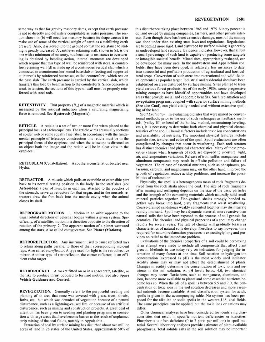
same way as that for gravity masonry dams, except that earth pressure is not so directly and definitely computable as water pressure. The section shown in (b) will need less masonry because its shape causes it to make use of some of the vertical weight of earth as a stabilizing earth pressure. Also, it is keyed into the ground so that the resistance to sliding is greatly increased. A cantilever retaining wall, shown in (c), is the one with a minimum of masonry, but, because its resistance to overturning is obtained by bending action, internal moments are developed which require that this type of wall be reinforced with steel. A counterfort retaining wall (d) is made up of a continuous vertical slab which is connected to a continuous horizontal base slab or footing and supported at intervals by reinforced buttresses, called counterforts, which rest on the base slab. The earth pressure is carried by the vertical slab, which transfers this load by beam action to the counterforts. Since concrete is weak in tension, the sections of this type of wall must be properly reinforced with steel rods.
RETENTIVITY. That property (Brs) of a magnetic material which is measured by the residual induction when a saturating magnetizing force is removed. See Hysteresis (Magnetic).
RETICLE. A reticle is a set of two or more fine wires placed at the principal focus of a telescope lens. The reticle wires are usually sections of spider web or some equally fine fiber. In accordance with the fundamental principle of telescope construction this reticle must be in the principal focus of the eyepiece, and when the telescope is directed on an object both the image and the reticle will be in clear view in the eyepiece.
RETICULUM (Constellation). A southern constellation located near Hydra.
RETRACTOR. A muscle which pulls an eversible or extensible part back to its normal resting position in the body. In the starfishes (see Asteroidea) a pair of muscles in each ray, attached to the pouches of the stomach, serve as retractors for that organ, and in the mussels retractors draw the foot back into the mantle cavity when the animal closes its shell.
RETROGRADE MOTION. I. Motion in an orbit opposite to the usual orbital direction of celestial bodies within a given system. Specifically, of a satellite, motion in a direction opposite to the direction of rotation of the primary. 2. The apparent motion of a planet westward among the stars. Also called retrogression. See Planet (Motions).
RETROREFLECTOR. Any instrument used to cause reflected rays to return along paths parallel to those of their corresponding incident rays. Also called retroflector. A type used for light is the retrodirective mirror. Another type of retroreflector, the corner reflector, is an efficient radar target.
RETROROCKET. A rocket fitted on or in a spacecraft, satellite, or the like to produce thrust opposed to forward motion. See also Space Vehicle Guidance and Control.
REVEGETATION. Generally refers to the purposeful seeding and planting of an area that once was covered with grass, trees, shrubs, forbs, etc., but which was denuded of vegetation because of a natural disturbance, such as a lightning-caused fire, or because of an artificial disturbance, such as mining and construction projects. A great deal of attention has been given to seeding and planting programs in connection with large areas that have become barren as the result of unplanned strip mining of the coal fields, notably in Appalachia.
Extraction of coal by surface mining has disturbed about two million acres of land in 26 states of the United States, approximately 50% of
REVEGETATION 2681
this disturbance taking place between 1965 and 197 5. Ninety percent is on land owned by mining companies, farmers, and other private interests. Even though there has been extensive damage, most of the mining was done under then existing state laws and regulations. Regulations are becoming more rigid. Land disturbed by surface mining is generally an undeveloped land resource. Evidence indicates, however, that all but a small percentage of such land is capable of producing some tangible or intangible societal benefit. Mined sites, appropriately reshaped, can be developed for many uses. In the midwestern and Appalachian coal fields, they have been developed, in relatively few instances to date, into successful and profitable production of agricultural and horticultural crops. Conversion of such areas into recreational and wildlife developments is a popular target. Industrial and residential sites have been established on areas disturbed by surface mining. Sites planted to trees yield various forest products. As of the early 1980s, some progressive mining companies have identified opportunities and have developed areas that provide social and economic benefits. Such reclamation and revegetation programs, coupled with superior surface mining methods (See also Coal), can yield vitally needed coal without extensive spoiling of the land.
Spoil Evaluation. In evaluating old sites that were mined by conventional methods, prior to the use of such techniques as haulback methods, (valley fill or head-of-the-hollow method, mountaintop leveling, etc.), it is necessary to determine both chemical and physical characteristics of the spoil. Chemical factors include toxic ion concentrations and availability of nutrients. The important physical features include particle size, texture, and color of the spoil. Spoil evaluations are often complicated by changes that occur in weathering. Each rock stratum has distinct chemical and physical characteristics. Many of these properties change when fragments of rock are exposed to moisture, light, air, and temperature variations. Release of iron, sulfur, manganese, and aluminum compounds may result in off-site pollution and failure of vegetation. The release of essential nutrients, such as phosphorus, potassium, calcium, and magnesium may, on the other hand, improve the growth of vegetation, reduce acidity problems, and increase the possibilities of reclamation.
Physically, the spoil is a heterogeneous mass of rock fragments derived from the rock strata above the coal. The size of rock fragments after mining and reshaping depends on the size of the basic particles and the strength of the cementing materials which naturally hold small mineral particles together. Fine-grained shales strongly bonded together may break into hard, platy fragments that resist weathering. Coarse-grained sandstones weakly cemented together may disintegrate rapidly into sand. Spoil may be a dynamic material, more reactive than natural soils that have been exposed to the process of soil genesis for centuries. The chemical and physical properties of a spoil may change rapidly for several years. The rate of change will gradually lessen as characteristics of natural soils develop. Needless to say, however, time required for natural reclamation processes is exceedingly long and provides no relief to the immediate problem.
Evaluations of the chemical properties of a soil could be perplexing if au attempt were made to include all components that affect plant growth. Methods in use today rely on indicators for judging the interaction of many factors at one time. Soil reaction or hydrogen ion concentration (expressed as pH) is the most widely used indicator. Acidity alone may or may not affect the establishment of plants. Changes in acidity determine the concentration of toxic ions and nutrients in the soil solution. At pH levels below 4.0, two chemical changes may occur: Toxic ions, such as manganese, aluminum, and iron, become more available to plants and some essential nutrients become less so. When the pH of a spoil is between 5.5 and 7 .0, the concentration of toxic ions in the soil solution decreases and more essential nutrients become available. A soil classification system for acidic spoils is given in the accompanying table. No system has been proposed for the alkaline or sodic spoils in the western U.S. coal fields. The same principles can be applied, but the toxic ions or cations may differ.
Other chemical analyses have been considered for identifying characteristics that result in specific nutrient deficiencies or toxicities. Phosphorus is often deficient (0 to 7 parts per million) in spoil material. Several laboratory analyses provide estimates of plant-available phosphorus. Total soluble salts in the soil solution may be important
2682
Class Number
I 2 3 4 5
Group
A B c
REVEGETATION
SYSTEM FOR CLASSIFYING SPOILS (ACIDIC)
Description
Toxic Marginal Acid' Calcareous Mixed
Acidity
pH Value
Less than 4.0 Less than 4.0 4.0 to 6.9 7.0 or more (Too varied to be classified as any above)
Texture
Description of Texture
Chiefly sand, sandstones, or sandy shales Chiefly loamy materials and silty shales Chiefly clay and clay shales
Extent on Area Sampled
More than 75% 50 to 75% 50 to 75% More than 50%
Combine acidity and textural classes to describe spoil type.
'Acid spoils may be subdivided into two classes: pH 4.1 to 5.4; and pH 5.5 to 6.9.
SOURCE: Northeastern Forest Experiment Station, Forest Service, U.S. Department of Agriculture.
for the very strongly acid or alkaline spoils. This does not necessarily mean high concentrations of sodium salts, but salts of all anions and cations in the soil solution. Some consideration has been given to laboratory analyses that give concentrations of exchangeable aluminum, manganese, and hydrogen. These analyses can identify specific toxicities and thus permit the selection of tolerant plant materials. Research has been initiated to determine whether the heavy metals, such as copper, zinc, nickel, mercury, and cobalt, occur in concentrations toxic to plants.
Texture and clay mineralogy influence the degree of compaction that results from heavy equipment passing over the surface during mining and reshaping. There is evidence that compaction may limit plant growth by reducing water infiltration and nutrient release. Texture may also determine the rate of release of toxic ions or nutrients from soil particles. Smaller particles expose a larger surface area per unit volume to the forces of weathering than coarse fragments. This results in a more rapid release of chemicals. Surface color is important because it influences heat exchange at the spoil surface. Dark materials absorb solar energy so the spoil may attain temperatures lethal to plants. The degree of risk depends on the season of the year, the slope of the exposed surface, and the exposure of the site. The highest risk may occur during summer months on steep slopes of black or dark gray material faoing south or west.
Preparation of the Site. Treatments to prepare the site for seeding or planting are determined after evaluation of site data and establishment of the land-management options and objectives. Grass and legumes often require more surface preparation than trees and shrubs. Uncompacted fill slopes and freshly reshaped surfaces may make acceptable seedbeds. Hard crusts form on many spoils; fine clay-size particles are consolidated by the drying action of wind and sun. This crust may be broken by rainfall, frost, or mechanical scarification. In many cases, ground cover will be denser if it is seeded into fresh spoil or where spoil surfaces have been broken by natural or mechanical scarification.
Treatment to create special surface configurations may be required on toxic spoils, on steep slopes, or in geographical locations where precipitation is low or unfavorably distributed throughout the year. rows or depressions, made by machinery, trap precipitation, moderate wind velocities, reduced evapotranspiration rates, and moderate spoil temperature extremes. The orientation of the furrows with respect to direction of slope, exposure to sun, or prevailing winds may determine the effectiveness of the treatment. Amendments to modify acidity
should be applied weeks or months before seeding. Scarification will mix the ameliorating material into the top 6 to 8 inches of spoil and create a neutralized layer for root development. On extremely rocky spoils where scarification is not practical, frost action and infiltrating water may carry the neutralizing materials below the spoil surface. The rate of application of neutralizing material depends on the type of vegetation to be seeded, the present and predicted acidity of the surface spoil, and the neutralizing capacity of the material used. Agricultural limestone is preferred for most treatments, but it can be used only in areas accessible to application equipment. No practical system has been developed for applying large amounts of agricultural limestone to steeply sloping land. Small quantities of lime can be applied with a hydroseeder to steep slopes. Finely ground limestone or hydrated lime may be mixed with water to form a slurry. Repeated applications may be necessary to achieve high rates per acre. The cost of repeated treatments could make this procedure impractical. Alkaline power plant fly ash and bottom ash are neutralizing materials, but they are usually not as effective as limestone. Fly ash contains various quantities of essential plant nutrients, such as phosphorus, zinc, molybdenum, and boron. However symptoms of boron toxicity have been observed on plants growing on sites treated with large amounts of fly ash. Rock phosphate provides a slowly available source of phosphorus and helps to neutralize acidity. Spoil acidity may react with rock phosphate to slowly release plant-available phosphorus.
Fertilization is generally recommended for grass and legume crops. Nitrogen and phosphorus have been used to accelerate the growth of trees on spoils. Tests show that most spoils are deficient in nitrogen. Phosphorus occurs in various concentrations, but deficiencies often limit plant growth. Potassium is usually adequate. There is little information about the concentrations of other nutrients. For most land-management objectives, the formulation of the fertilizer makes little difference when equivalent rates are applied. High-analysis fertilizers, ammonium nitrate, triple superphosphate, and ammonium phosphate are often preferred. Using low-analysis fertilizers on sites that require high rates of application may increase the total soluble-salt concentration to levels toxic to some plants.
Rates of fertilization vary with the seeded crop, the inherent fertility of the spoil, and the land-management objective. Nitrogen and phosphorus at 50 and 22 pounds per acre (56 and 246 kilograms per hectare) respectively, are sufficient to establish grass on many spoils. Higher rates of phosphate are important for legumes. More consideration is being given to retreatment at regular intervals. Multiple treatments are attractive because they reduce the chance of unacceptable cover and increase the probability of achieving land use objectives within the shortest time.
Much research on fertilizer application remains to be done. Research results thus far show that placing selected fertilizers in or near the planting hole increases the growth of black locust. This leguminous species responded to additions of nitrogen and phosphorus placed near seedlings on extremely acid spoil. In other trials, direct-seeded black locust made more rapid growth after surface applications of nitrogen and phosphorus. Five tons of lime per acre per foot of soil increased the growth ofloblolly, shortleaf, Virginia, and a hybrid (pitch/loblolly) pine planted in extremely acid spoil. Pitch pine did not respond to the liming treatments. Ten tons of lime per acre-foot reduced the growth of the pines.
Municipal waste products have been considered for surface-mine reclamation. Waste applications could improve soil texture, add essential plant nutrients, and provide mulch for seed and seedlings. Shredded or composted waste could be applied to the surface, and mechanical methods could be used to incorporate it into the spoil. Sewage sludge can be applied in water slurry or in dried form. Mixtures of shredded or composted waste and sewage sludge offer another possibility. Thus far, use of these materials has been restricted to relatively small demonstration areas for public health reasons.
Seeding and Planting. For each of the major coal-producing regions in the United States, there is a group of preferred plant species. These may be grouped under four major categories: (1) grasses: (2) forbs; (3) trees; and (4) shrubs. The grasses and forbs may be further classified as (a) temporary; (b) semipermanent; and (c) permanent, depending on life expectancy of the plant. Temporary species give prompt and effective site protection by reason of quick growth, fibrous roots, and ability
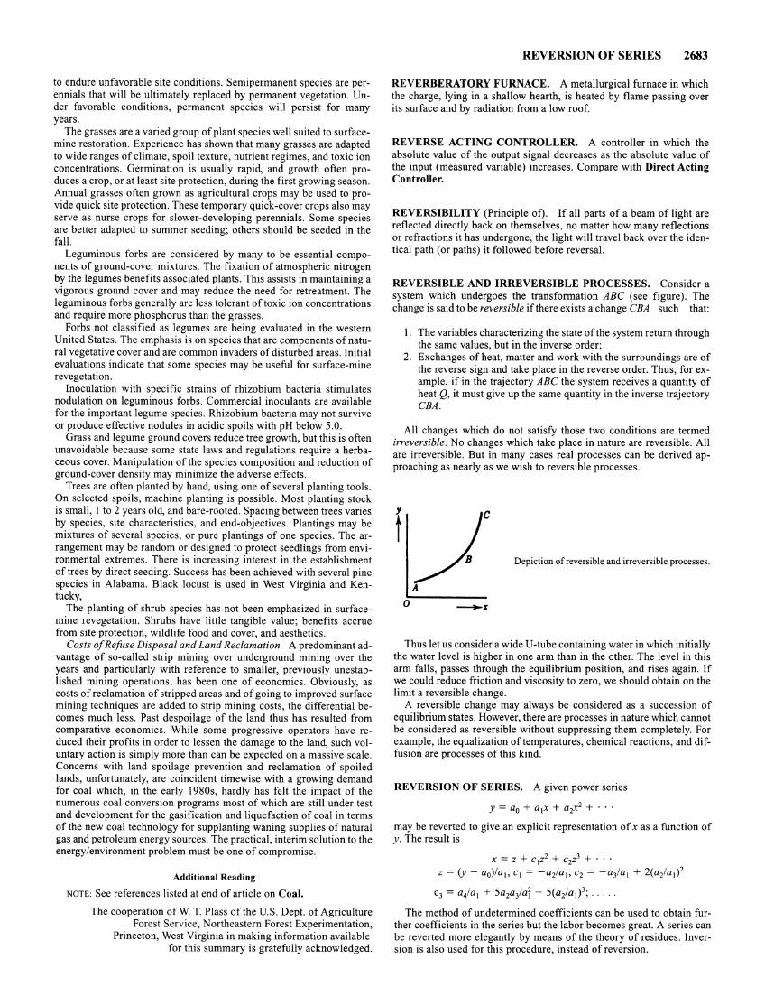
to endure unfavorable site conditions. Semipermanent species are perennials that will be ultimately replaced by permanent vegetation. Under favorable conditions, permanent species will persist for many years.
The grasses are a varied group of plant species well suited to surfacemine restoration. Experience has shown that many grasses are adapted to wide ranges of climate, spoil texture, nutrient regimes, and toxic ion concentrations. Germination is usually rapid, and growth often produces a crop, or at least site protection, during the first growing season. Annual grasses often grown as agricultural crops may be used to provide quick site protection. These temporary quick-cover crops also may serve as nurse crops for slower-developing perennials. Some species are better adapted to summer seeding; others should be seeded in the fall.
Leguminous forbs are considered by many to be essential components of ground-cover mixtures. The fixation of atmospheric nitrogen by the legumes benefits associated plants. This assists in maintaining a vigorous ground cover and may reduce the need for retreatment. The leguminous forbs generally are less tolerant oftoxic ion concentrations and require more phosphorus than the grasses.
Forbs not classified as legumes are being evaluated in the western United States. The emphasis is on species that are components of natural vegetative cover and are common invaders of disturbed areas. Initial evaluations indicate that some species may be useful for surface-mine revegetation.
Inoculation with specific strains of rhizobium bacteria stimulates nodulation on leguminous forbs. Commercial inoculants are available for the important legume species. Rhizobium bacteria may not survive or produce effective nodules in acidic spoils with pH below 5.0.
Grass and legume ground covers reduce tree growth, but this is often unavoidable because some state laws and regulations require a herbaceous cover. Manipulation of the species composition and reduction of ground-cover density may minimize the adverse effects.
Trees are often planted by hand, using one of several planting tools. On selected spoils, machine planting is possible. Most planting stock is small, 1 to 2 years old, and bare-rooted. Spacing between trees varies by species, site characteristics, and end-objectives. Plantings may be mixtures of several species, or pure plantings of one species. The arrangement may be random or designed to protect seedlings from environmental extremes. There is increasing interest in the establishment of trees by direct seeding. Success has been achieved with several pine species in Alabama. Black locust is used in West Virginia and Kentucky,
The planting of shrub species has not been emphasized in surfacemine revegetation. Shrubs have little tangible value; benefits accrue from site protection, wildlife food and cover, and aesthetics.
Costs of Refuse Disposal and Land Reclamation. A predominant advantage of so-called strip mining over underground mining over the years and particularly with reference to smaller, previously unestablished mining operations, has been one of economics. Obviously, as costs of reclamation of stripped areas and of going to improved surface mining techniques are added to strip mining costs, the differential becomes much less. Past despoilage of the land thus has resulted from comparative economics. While some progressive operators have reduced their profits in order to lessen the damage to the land, such voluntary action is simply more than can be expected on a massive scale. Concerns with land spoilage prevention and reclamation of spoiled lands, unfortunately, are coincident timewise with a growing demand for coal which, in the early 1980s, hardly has felt the impact of the numerous coal conversion programs most of which are still under test and development for the gasification and liquefaction of coal in terms of the new coal technology for supplanting waning supplies of natural gas and petroleum energy sources. The practical, interim solution to the energy/environment problem must be one of compromise.
Additional Reading
NOTE: See references listed at end of article on Coal.
The cooperation ofW. T. Plass of the U.S. Dept. of Agriculture Forest Service, Northeastern Forest Experimentation,
Princeton, West Virginia in making information available for this summary is gratefully acknowledged.
REVERSION OF SERIES 2683
REVERBERATORY FURNACE. A metallurgical furnace in which the charge, lying in a shallow hearth, is heated by flame passing over its surface and by radiation from a low roof.
REVERSE ACTING CONTROLLER. A controller in which the absolute value of the output signal decreases as the absolute value of the input (measured variable) increases. Compare with Direct Acting Controller.
REVERSIBILITY (Principle of). If all parts of a beam of light are reflected directly back on themselves, no matter how many reflections or refractions it has undergone, the light will travel back over the identical path (or paths) it followed before reversal.
REVERSIBLE AND IRREVERSIBLE PROCESSES. Consider a system which undergoes the transformation ABC (see figure). The change is said to be reversible if there exists a change CBA such that:
1. The variables characterizing the state of the system return through the same values, but in the inverse order;
2. Exchanges of heat, matter and work with the surroundings are of the reverse sign and take place in the reverse order. Thus, for example, if in the trajectory ABC the system receives a quantity of heat Q, it must give up the same quantity in the inverse trajectory CBA.
All changes which do not satisfy those two conditions are termed irreversible. No changes which take place in nature are reversible. All are irreversible. But in many cases real processes can be derived approaching as nearly as we wish to reversible processes.
Depiction of reversible and irreversible processes.
0 ---%
Thus let us consider a wide U -tube containing water in which initially the water level is higher in one arm than in the other. The level in this arm falls, passes through the equilibrium position, and rises again. If we could reduce friction and viscosity to zero, we should obtain on the limit a reversible change.
A reversible change may always be considered as a succession of equilibrium states. However, there are processes in nature which cannot be considered as reversible without suppressing them completely. For example, the equalization of temperatures, chemical reactions, and diffusion are processes of this kind.
REVERSION OF SERIES. A given power series
y = a0 + a1x + a 2x2 + · · · may be reverted to give an explicit representation of x as a function of y. The result is
X = Z + c1z2 + c2z3 + · · · z = (y- a0)/a 1; c1 = -a2/a 1; c2 = -a3/a 1 + 2(a2/a 1) 2
c3 = a4/a 1 + 5a2aiar - 5(a2/a 1) 3 ; .....
The method of undetermined coefficients can be used to obtain further coefficients in the series but the labor becomes great. A series can be reverted more elegantly by means of the theory of residues. Inversion is also used for this procedure, instead of reversion.
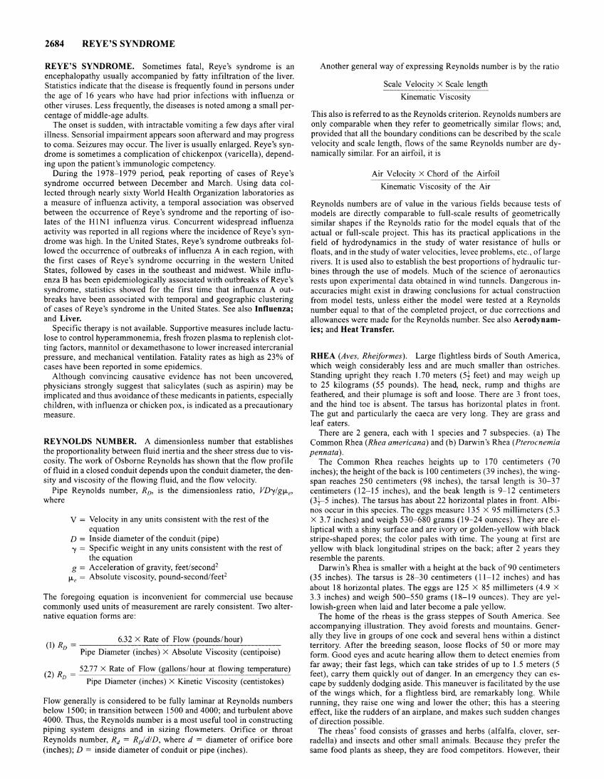
2684 REYE'S SYNDROME
REYE'S SYNDROME. Sometimes fatal, Reye's syndrome is an encephalopathy usually accompanied by fatty infiltration of the liver. Statistics indicate that the disease is frequently found in persons under the age of 16 years who have had prior infections with influenza or other viruses. Less frequently, the diseases is noted among a small percentage of middle-age adults.
The onset is sudden, with intractable vomiting a few days after viral illness. Sensorial impairment appears soon afterward and may progress to coma. Seizures may occur. The liver is usually enlarged. Reye's syndrome is sometimes a complication of chickenpox (varicella), depending upon the patient's immunologic competency.
During the 1978-1979 period, peak reporting of cases of Reye's syndrome occurred between December and March. Using data collected through nearly sixty World Health Organization laboratories as a measure of influenza activity, a temporal association was observed between the occurrence of Reye's syndrome and the reporting of isolates of the HlNl influenza virus. Concurrent widespread influenza activity was reported in all regions where the incidence of Reye 's syndrome was high. In the United States, Reye's syndrome outbreaks followed the occurrence of outbreaks of influenza A in each region, with the first cases of Reye's syndrome occurring in the western United States, followed by cases in the southeast and midwest. While influenza B has been epidemiologically associated with outbreaks ofReye's syndrome, statistics showed for the first time that influenza A outbreaks have been associated with temporal and geographic clustering of cases of Reye's syndrome in the United States. See also Influenza; and Liver.
Specific therapy is not available. Supportive measures include lactulose to control hyperammonemia, fresh frozen plasma to replenish clotting factors, mannitol or dexamethasone to lower increased intercranial pressure, and mechanical ventilation. Fatality rates as high as 23% of cases have been reported in some epidemics.
Although convincing causative evidence has not been uncovered, physicians strongly suggest that salicylates (such as aspirin) may be implicated and thus avoidance of these medicants in patients, especially children, with influenza or chicken pox, is indicated as a precautionary measure.
REYNOLDS NUMBER. A dimensionless number that establishes the proportionality between fluid inertia and the sheer stress due to viscosity. The work of Osborne Reynolds has shown that the flow profile of fluid in a closed conduit depends upon the conduit diameter, the density and viscosity of the flowing fluid, and the flow velocity.
Pipe Reynolds number, RD, is the dimensionless ratio, VD-ylg!Le, where
V = Velocity in any units consistent with the rest of the equation
D = Inside diameter of the conduit (pipe) -y = Specific weight in any units consistent with the rest of
the equation g = Acceleration of gravity, feet/second2
ILe = Absolute viscosity, pound-second/feet2
The foregoing equation is inconvenient for commercial use because commonly used units of measurement are rarely consistent. Two alternative equation forms are:
6.32 X Rate of Flow (pounds/hour) (I) R - _________ _::c_ ___ c___ __
D - Pipe Diameter (inches) X Absolute Viscosity (centipoise)
(2) R = 52.77 X Rate of Flow (gallons/hour at flowing temperature)
D Pipe Diameter (inches) X Kinetic Viscosity (centistokes)
Flow generally is considered to be fully laminar at Reynolds numbers below 1500; in transition between 1500 and 4000; and turbulent above 4000. Thus, the Reynolds number is a most useful tool in constructing piping system designs and in sizing flowmeters. Orifice or throat Reynolds number, Rd = RD/d!D, where d = diameter of orifice bore (inches); D = inside diameter of conduit or pipe (inches).
Another general way of expressing Reynolds number is by the ratio
Scale Velocity X Scale length
Kinematic Viscosity
This also is referred to as the Reynolds criterion. Reynolds numbers are only comparable when they refer to geometrically similar flows; and, provided that all the boundary conditions can be described by the scale velocity and scale length, flows of the same Reynolds number are dynamically similar. For an airfoil, it is
Air Velocity X Chord of the Airfoil
Kinematic Viscosity of the Air
Reynolds numbers are of value in the various fields because tests of models are directly comparable to full-scale results of geometrically similar shapes if the Reynolds ratio for the model equals that of the actual or full-scale project. This has its practical applications in the field of hydrodynamics in the study of water resistance of hulls or floats, and in the study of water velocities, levee problems, etc., of large rivers. It is used also to establish the best proportions of hydraulic turbines through the use of models. Much of the science of aeronautics rests upon experimental data obtained in wind tunnels. Dangerous inaccuracies might exist in drawing conclusions for actual construction from model tests, unless either the model were tested at a Reynolds number equal to that of the completed project, or due corrections and allowances were made for the Reynolds number. See also Aerodynamics; and Heat Transfer.
RHEA (Aves, Rheiformes). Large flightless birds of South America, which weigh considerably Jess and are much smaller than ostriches. Standing upright they reach 1.70 meters (5~ feet) and may weigh up to 25 kilograms (55 pounds). The head, neck, rump and thighs are feathered, and their plumage is soft and loose. There are 3 front toes, and the hind toe is absent. The tarsus has horizontal plates in front. The gut and particularly the caeca are very long. They are grass and leaf eaters.
There are 2 genera, each with I species and 7 subspecies. (a) The Common Rhea (Rhea americana) and (b) Darwin's Rhea (Pterocnemia pennata).
The Common Rhea reaches heights up to 170 centimeters (70 inches); the height of the back is 100 centimeters (39 inches), the wingspan reaches 250 centimeters (98 inches), the tarsal length is 30-37 centimeters ( 12-15 inches), and the beak length is 9-12 centimeters (3}-5 inches). The tarsus has about 22 horizontal plates in front. Albinos occur in this species. The eggs measure 135 X 95 millimeters (5.3 X 3.7 inches) and weigh 530-680 grams (19-24 ounces). They are elliptical with a shiny surface and are ivory or golden-yellow with black stripe-shaped pores; the color pales with time. The young at first are yellow with black longitudinal stripes on the back; after 2 years they resemble the parents.
Darwin's Rhea is smaller with a height at the back of 90 centimeters (35 inches). The tarsus is 28-30 centimeters (11-12 inches) and has about 18 horizontal plates. The eggs are 125 X 85 millimeters (4.9 X 3.3 inches) and weigh 500-550 grams (18-19 ounces). They are yellowish-green when laid and later become a pale yellow.
The home of the rheas is the grass steppes of South America. See accompanying illustration. They avoid forests and mountains. Generally they live in groups of one cock and several hens within a distinct territory. After the breeding season, loose flocks of 50 or more may form. Good eyes and acute hearing allow them to detect enemies from far away; their fast legs, which can take strides of up to 1.5 meters (5 feet), carry them quickly out of danger. In an emergency they can escape by suddenly dodging aside. This maneuver is facilitated by the use of the wings which, for a flightless bird, are remarkably long. While running, they raise one wing and lower the other; this has a steering effect, like the rudders of an airplane, and makes such sudden changes of direction possible.
The rheas' food consists of grasses and herbs (alfalfa, clover, serradella) and insects and other small animals. Because they prefer the same food plants as sheep, they are food competitors. However, their
4
6
Areas inhabited by the Rheas, including subspecies. Rhea (Rhea americana);(!) Rhea americana americana; (2) Rhea americana intermedia; (3) Rhea americana a/bescens; (4, 5) Rhea americana araneiceps; Darwin's Rhea (Pterocnemia pennata); (6) Pterocnemia pennata pennata; (7) Pterocnemia pennata garleppi.
consumption of the burrlike seeds which tangle the wool of sheep also make them useful. If they find enough juicy plants, they require very little water.
In the breeding season between September and December, earlier in the north than in the south, the cock expels all rivals from his territory. He only tolerates hens. The courtship display consists of his running around with his plumage erected, dodging sideways and swinging the neck from side to side. At this time he gives his deep call, which can be heard far away, "nan-du," which is responsible for one of its names, "nandu." The cock builds the nest, a simple depression lined with a few pieces of plants; only the cock incubates. Each hen lays her eggs outside the nest at two day intervals. Usually there are 15 to 20 eggs in a clutch; since each hen lays I 0 to 15 eggs and several hens lay for their cock, it hardly matters if many eggs are lost. Nests containing up to 80 eggs have been found. But the cock, during incubation, cannot cover so many and hence he cannot hatch them all. The young hatch after about 40 days of incubation. After half a year, they reach adult size, and at 2 to 3 years they are capable of reproduction. See also Ratites.
RHEBOK. See Antelope.
RHEIFORMES. See Rhea.
RHENIUM. Chemical element, symbol Re, at. no. 75, at. wt. 186.2, periodic table group 7, mp 3180°C, bp 5627°C, density 21.04 g/cm3
(20°C). Elemental rhenium has a close-packed hexagonal crystal structure.
Rhenium is a platinum-white, very hard metal; stable in air below 600°C (at this temperature, the metal begins to generate a white, nonpoisonous, vaporous oxide, Re20 7); practically insoluble in HCI or hydrofluoric acid, but soluble in HN03 with the formation of perrhenic acid; forms sodium rhenate when fused with NaOH and nitrate. Discovered by Noddack and Tacke in 1925 in tantalite, wolframite, and columbite by the Moseley x-ray spectrographic method of analysis, and later found present in molybdenite, from which rhenium is obtained. Predicted by Mendeleev, in 1871 , as an element to be discovered with properties resembling manganese, and named by him dvimanganese.
There are two natural isotopes, 185Re and 187Re, of which the latter is radioactive with respect to beta decay, having a half-life of 5 X I 010
years reverting to 1870s. Other radioactive isotopes include 177Re, 178Re, 180Re, 183Re, 184Re, 186Re, 188Re, and 189Re. The latter isotope has a long half-life, something less than I 03 years; the half-lives of the remaining isotopes are comparatively short, measured in minutes, hours, or days.
Because Re and Os are highly refractory and siderophilic elements, the Re-Os isotope system is important in studies concerned with metal phases and high-temperature inclusions of meteorites. R. J. Walker (Carnegie Institute of Washington) and J. W. Morgan (U.S. Geological Survey) observe, "Potential applications of the system include dating meteorites, especially with respect to the chronology of the assembly and subsequent metamorphism of genetically disparate components, and providing estimates of the initial Os isotopic composition and Re/Os ratio of the early earth. This ratio is an important chemical tracer
RHENIUM 2685
for understanding the formation of the earth's core and the chemical evolution of the mantle and crust."
In terms of abundance, rhenium ranks 75th among the elements, based upon estimated contents of the universe. Rhenium is not plentiful in the earth's crust, being essentially confined to association with the mineral molybdenite. First ionization potential, 7.87 eV Oxidation potentials Re + 4H20 ~ReO,)+ 8H+ + 7e-,-0.15 V; Re + 80H- ~ ReO,) + 4H20 + 7e-, 0.81 V Other important physical properties of rhenium are given under Chemical Elements.
Rhenium is a minor constituent (100 ppb) of molybdenite-bearing porphyry copper ores, of which there is extensive mining in the United States and South America. Commercial rhenium is recovered from byproduct molybdenum. As the result of roasting MoS2 and Mo03, the rhenium is concentrated to levels of 300- 1,000 ppm. At the high process temperatures, the rhenium is oxidized and volatilized as rhenium heptoxide, Re20 7. This compound is recovered from flue gases by way of wet scrubbing and chemical separation techniques as the relatively crude ammonium perrhenate. The latter compound is reduced with hydrogen to produce rhenium metal.
Uses: Rhenium finds rather wide use as a catalyst in selective hydrogenation and other chemical reactions. It sometimes is used in conjunction with platinum in reforming operations. Additional processes for which rhenium has been tested and used as a catalyst include alkylation, dealkylation, dehydrochlorination, dehydrogenation, dehydroisomerization, enrichment of water, hydrocracking, and oxidation. The outstanding feature of rhenium catalysts is their high selectivity, very important in hydrogenation reactions. Rhenium catalysts also resist such catalyst poisons as nitrogen, sulfur, and phosphorus. In terms of activity, rhenium commonly surpasses cobalt, molybdenum, and tungsten type catalysts and approximates palladium, nickel, and platinum catalysts.
Because of the very heavy ionic weight (250) of the perrhenate ion, it is one of the heaviest simple anions obtainable in readily soluble salts. It has found use as a precipitant for potassium and some other heavy univalent ions; also as a precipitant for such complex ions as Co(NH3)~+, and for the separation of alkaloids and organic bases. Perrhenate also is used in the fractional crystallization of the rare-earth elements.
When rhenium is added to other refractory metals, such as molybdenum and tungsten, ductility and tensile strength are improved. These improvements persist even after heating above the recrystallization temperature. An excellent example is the complete ductility shown by a molybdenum-rhenium fusion weld. Rhenium and rhenium alloys have gained some acceptance in semiconductor, thermocouple, and nuclear reactor applications. The alloys also are used in gyroscopes, miniature rockets, electrical contacts, electronic-tube components, and thermionic converters.
Because rhenium is very difficult to machine with carbide tools and other conventional methods, electrical-discharge machining (EDM), electrochemical machining (ECM), abrasive cutting, or grinding is recommended.
Rhenium can be consolidated by powder metallurgy techniques, inert-atmosphere arc melting, and thermal decomposition of volatile halides. In the powder metallurgy process, bars are pressed at 200 MPa, and this is followed by vacuum sintering at 1200°C and hydrogen sintering at 2700°C. Rhenium is usually fabricated from sintered bar by cold working, following by annealing. Reductions of I 0-20% can be taken with intermediate anneals for one to two hours at 1700°C. Primary working is by rolling, swaging, or forging. Wire drawing is possible down to 2 mils for strip and wire. Because of its excellent ductility at room temperature, rhenium is suitable for forming of complex shapes (Knipple, 1979).
The cost and scarcity of pure rhenium preclude its extensive use for large structural components. Typical applications include wear-resistant electrical contacts and mass spectrometer cathodes. Rhenium also is being studied for use in the reactor core of space nuclear power systems as, for example, fuel-pin liners that prevent interaction with the fuel and also provide high neutron capture under some operating conditions. Rhenium coatings are used to enhance the heat resistance of carbon and graphite parts in low-oxygen environments. Tungsten and molybdenum alloys containing rhenium have been used for heating elements, compact electromagnetic coils, high-temperature thermocou-
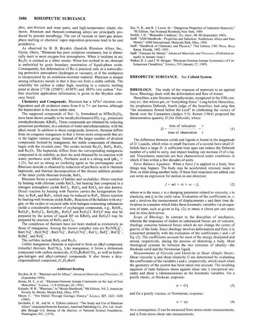
2686 RHEOPECTIC SUBSTANCE
pies, anti-friction and wear parts, and high-temperature elastic elements. Rhenium and rhenium-containing alloys are principally produced by powder metallurgy. The use of vacuum or inert-gas atmosphere melting or chemical vapor deposition processes tend to be cost prohibitive.
As observed by B. D. Bryskin (Sandvik Rhenium Alloys Inc., Elyria, Ohio), "Rhenium has poor oxidation resistance, but is chemically inert in most oxygen-free atmospheres. When it oxidizes in air, Re20 7 is emitted as a white smoke. When hot worked in air, rhenium is embrittled by grain boundary penetration of liquid-phase oxide. Consequently, hot deformation of Re is practical only in a nonoxidizing protective atmosphere (hydrogen or vacuum), or if the workpiece is encapsulated by an oxidation-resistant material. Rhenium is unique among refractory metals in that it does not form a stable carbide. The solubility for carbon is rather high, resulting in a eutectic melting point at about 2773K (2500°C; 4530°F) and .085% (wt) carbon." Further excellent application information is given in the Bryskin reference listed.
Chemistry and Compounds. Rhenium has a 5d56s2 electron configuration and all oxidation states from 0 to 7 + are known, although the heptavalent is the most stable state.
The supposed compounds of Re(- I), formulated as M1Re(H20)4 ,
have been shown actually to be tetrahydrorhenates(III), e.g., potassium tetrahydrorhenate, KReH4 . These compounds are obtained by reducing potassium perrhenate, in a solution of water and ethanolamine, with the alkali metal. In addition to these compounds, however, rhenium differs from its congener manganese in that it forms more compounds that are in the higher valence group. Instead of the larger number of divalent compounds formed by manganese, the stable compounds of rhenium begin with the trivalent ones. The oxides include Re20 3, Re02, Re03,
and Re20 7. The heptoxide differs from the corresponding manganese compound in its stability, as does the acid obtained by its reaction with water, perrhenic acid, HRe04 . Perrhenic acid is a strong acid (pKA = 1.25), but not as strong an oxidizing agent as the permanganic acid. Rhenium dioxide is obtained by reduction of perrhenic acid or rhenium heptoxide, and thermal decomposition of the dioxan addition product of the latter yields rhenium trioxide, Re03•
Rhenium forms a number of halides and oxyhalides. Direct reaction by heating with chlorine yields ReCI5, but heating that compound in a nitrogen atmosphere yields ReCI3. ReC14 and ReCI6 are also known. Direct reaction by heating with fluorine carries the halogenation further, to ReF 6 and ReF 7, which may be reduced to ReF 4. Direct reaction by heating with bromine yields ReBr3. Reaction of the halides with oxygen, or the oxides or oxyacid salts with halogen-containing substances yields a considerable number of oxyhalogen compounds, e.g., ReOF4 ,
Re02F2, Re02Cl2, Re02Brz, Re03F and Re03Cl. Re03F may also be prepared by the action of liquid HF on KRe04 and Re03Cl may be prepared by reaction ofRe03 and Cl2.
The complexes of rhenium have not been studied as extensively as those of manganese. Among the known complex ions are Re(NH3)~+, Re(CN)t, Re(CN)~-, Re(CN)t, ReOiCN)~-, ReCI4, ReFt, ReCI~-, ReBr~- and Rei~-.
The sulfides include ReS2 and Re2S7.
Unlike manganese, rhenium is reported to form an alkyl compound, trimethyl rhenium, Re(CH3h Like manganese, it forms a dirhenium compound with carbon monoxide, (C0)5ReRe(C0)5, as well as hydrogen-halogen and alkyl-carbonyl compounds. It also forms a dicyclopentadienyl compound, (C5H5)ReH.
Additional Reading
Bryskin, B. D.: "Rhenium and Its Alloys," Advanced Materials and Processes, 22 (September 1992).
Horan, M. F., et a!.: "Rhenium-Osmium Isotope Constraints on the Age of Iron Meteorites," Science, 1118 (February 28, 1992).
Knipple, W. R.: "Rhenium," in "Metals Handbook," 9th Edition, Vol. 2, American Society for Metals, Metals Park, Ohio, 1979.
Meyer, C.: "Ore Metals Through Geologic History," Science, 227, 1421-1428 (1985).
Savittskii, E. M., and M. A. Tylkina (editors): "The Study and Use of Rhenium Alloys" (translated from the Russian), Amerind Publishing Co., Pvt. Ltd. Available through U.S. Bureau of the Interior, or National Science Foundation, Washington, D.C. (1978).
Sax, N. R., and R. J. Lewis, Sr.: "Dangerous Properties of Industrial Materials," 7th Edition, Van Nostrand Reinhold, New York, 1989.
Sinfelt, J. H.: "Bimetallic Catalysts," Sci. A mer., 90-98 (September 1985 ). Staff: "ASM Handbook-Properties and Selection: Nonferrous Alloys and Pure
Metals," ASM International, Materials Park, Ohio, 1990. Staff: "Handbook of Chemistry and Physicis," 73rd Edition, CRC Press, Boca
Raton, Florida, 1992-1993. Staff: "Forecast for Metals," Advanced Materials and Processes, (Published an
nually in January issue.) Walker, R. J., and J. W. Morgan: "Rhenium-Osmium Isotope Systematics of Car
bonaceous Chondrites," Science, 519 (January 27, 1989).
RHEOPECTIC SUBSTANCE. See Colloid System.
RHEOLOGY. The study of the response of materials to an applied force. Rheology deals with the deformation and flow of matter.
Heraclitus, a pre-Socratic metaphysician, recognized in the fifth century B.C. that 1TUVTa pEi, or "everything flows." Long before Heraclitus, the prophetess Deborah, fourth judge of the Israelites, had sung that "the mountains flowed before the Lord" in celebrating the victory of Barak over the Canaanites (Judges 5:5). Reiner (1964) proposed the dimensionless quantity D (for Deborah), where:
time of relaxation T D=~------ (I)
time of observation
The difference between solids and liquids is found in the magnitude of D. Liquids, which relax in small fractions of a second, have small D. Solids have a large D. A sufficient time span can reduce the Deborah number of a solid to unity, and impact loading can increase D of a liquid. Viscoelastic materials are best characterized under conditions in which D lies within a few decades of unity.
Force Balance Equation. When a forcefis applied to a body, four things may happen. The body may be accelerated, strained, made to flow, or slide along another body. If these four responses are added, one can write an expression for motion in one direction:
f= mx + rx + sx- fo (2)
where m is the mass, r is a damping parameter related to viscosity, s to elasticity, andf0 to the yield value. Evaluation of the coefficients m, r, and s involves the measurement of displacements x and their time derivatives in a manner which links these kinematic variables via an equation of state, such as given in Eq. (2), to stress u (force per unit area) and its time derivatives.
Scope of Rheology. In contrast to the discipline of mechanics, wherein the responses of bodies to unbalanced forces are of concern, rheology concerns balanced forces which do not change the center of gravity of the body. Since rheology involves deformation and flow, it is concerned primarily with the evaluation of the coefficients r and s of Eq. (2). The coefficients account for most of the energy dissipated and stored, respectively, during the process of distorting a body. Most rheological systems lie between the two extremes of ideality-the Hookean solid and the Newtonian liquid.
Measurements of Viscosity and Elasticity in Shear (Simple Shear). Shear viscosity TJ and shear elasticity G are determined by evaluating the coefficients of the variables i and x, respectively, which result when the geometry of the system has been taken into account. The resulting equation of state balances stress against shear rate "y (reciprocal seconds) and shear "Y (dimensionless) as the kinematic variables. For a purely elastic, or Hookean, response:
u = G"y (3)
and for a purely viscous, or Newtonian, response:
(f = TJ'Y (4)
As a consequence, G can be measured from stress-strain measurements, and 'T] from stress-shear rate measurements.
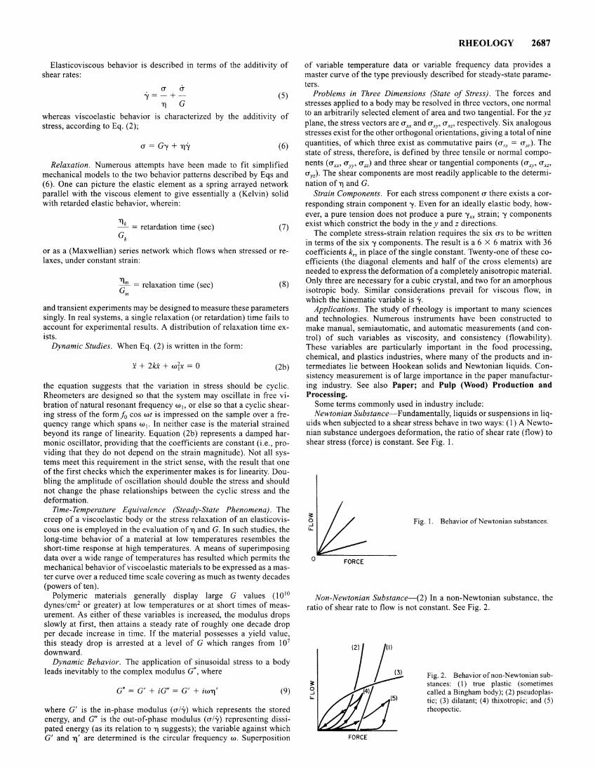
Elasticoviscous behavior is described in terms of the additivity of shear rates:
<T <T ..Y=-+-
1] G (5)
whereas viscoelastic behavior is characterized by the additivity of stress, according to Eq. (2);
u = G-y + TJ'Y (6)
Relaxation. Numerous attempts have been made to fit simplified mechanical models to the two behavior patterns described by Eqs and (6). One can picture the elastic element as a spring arrayed network parallel with the viscous element to give essentially a (Kelvin) solid with retarded elastic behavior, wherein:
T]k da 0 0
- = retar t10n time (sec) (7) Gk
or as a (Maxwellian) series network which flows when stressed or relaxes, under constant strain:
~m = relaxation time (sec) m
(8)
and transient experiments may be designed to measure these parameters singly. In real systems, a single relaxation (or retardation) time fails to account for experimental results. A distribution of relaxation time exists.
Dynamic Studies. When Eq. (2) is written in the form:
x + 2kX + wfx = 0 (2b)
the equation suggests that the variation in stress should be cyclic. Rheometers are designed so that the system may oscillate in free vibration of natural resonant frequency w1, or else so that a cyclic shearing stress of the form fo cos wt is impressed on the sample over a frequency range which spans w 1• In neither case is the material strained beyond its range of linearity. Equation (2b) represents a damped harmonic oscillator, providing that the coefficients are constant (i.e., providing that they do not depend on the strain magnitude). Not all systems meet this requirement in the strict sense, with the result that one of the first checks which the experimenter makes is for linearity. Doubling the amplitude of oscillation should double the stress and should not change the phase relationships between the cyclic stress and the deformation.
Time-Temperature Equivalence (Steady-State Phenomena). The creep of a viscoelastic body or the stress relaxation of an elasticoviscous one is employed in the evaluation ofT] and G. In such studies, the long-time behavior of a material at low temperatures resembles the short-time response at high temperatures. A means of superimposing data over a wide range of temperatures has resulted which permits the mechanical behavior of viscoelastic materials to be expressed as a master curve over a reduced time scale covering as much as twenty decades (powers often).
Polymeric materials generally display large G values (1 010
dynes/cm2 or greater) at low temperatures or at short times of measurement. As either of these variables is increased, the modulus drops slowly at first, then attains a steady rate of roughly one decade drop per decade increase in time. If the material possesses a yield value, this steady drop is arrested at a level of G which ranges from 107
downward. Dynamic Behavior. The application of sinusoidal stress to a body
leads inevitably to the complex modulus a·, where
G* = G' + iG" = G' + iwTJ' (9)
where G' is the in-phase modulus (u/'Y) which represents the stored energy, and G" is the out-of-phase modulus (u/'Y) representing dissipated energy (as its relation to TJ suggests); the variable against which G' and TJ' are determined is the circular frequency w. Superposition
RHEOLOGY 2687
of variable temperature data or variable frequency data provides a master curve of the type previously described for steady-state parameters.
Problems in Three Dimensions (State of Stress). The forces and stresses applied to a body may be resolved in three vectors, one normal to an arbitrarily selected element of area and two tangential. For the yz plane, the stress vectors are uxx and <Txy• uXZ' respectively. Six analogous stresses exist for the other orthogonal orientations, giving a total of nine quantities, of which three exist as commutative pairs (urs = usr). The state of stress, therefore, is defined by three tensile or normal components ( u xx• u YY' u zz) and three shear or tangential components ( u xy• u w
<Ty2). The shear components are most readily applicable to the determination of TJ and G.
Strain Components. For each stress component u there exists a corresponding strain component -y. Even for an ideally elastic body, however, a pure tension does not produce a pure 'Yxx strain; 'Y components exist which constrict the body in they and z directions.
The complete stress-strain relation requires the six us to be written in terms of the six 'Y components. The result is a 6 X 6 matrix with 36 coefficients k,s in place of the single constant. Twenty-one of these coefficients (the diagonal elements and half of the cross elements) are needed to express the deformation of a completely anisotropic material. Only three are necessary for a cubic crystal, and two for an amorphous isotropic body. Similar considerations prevail for viscous flow, in which the kinematic variable is -y.
Applications. The study of rheology is important to many sciences and technologies. Numerous instruments have been constructed to make manual, semiautomatic, and automatic measurements (and control) of such variables as viscosity, and consistency (flowability). These variables are particularly important in the food processing, chemical, and plastics industries, where many of the products and intermediates lie between Hookean solids and Newtonian liquids. Consistency measurement is of large importance in the paper manufacturing industry. See also Paper; and Pulp (Wood) Production and Processing.
Some terms commonly used in industry include: Newtonian Substance-Fundamentally, liquids or suspensions in liq
uids when subjected to a shear stress behave in two ways: (I) A Newtonian substance undergoes deformation, the ratio of shear rate (flow) to shear stress (force) is constant. See Fig. 1.
Fig. I. Behavior of Newtonian substances.
Non-Newtonian Substance-(2) In a non-Newtonian substance, the ratio of shear rate to flow is not constant. See Fig. 2.
;;:: 0 ..J "-
FORCE
(3) Fig. 2. Behavior of non-Newtonian substances: ( 1) true plastic (sometimes called a Bingham body); (2) pseudoplastic; (3) dilatant; (4) thixotropic; and (5) rheopectic.
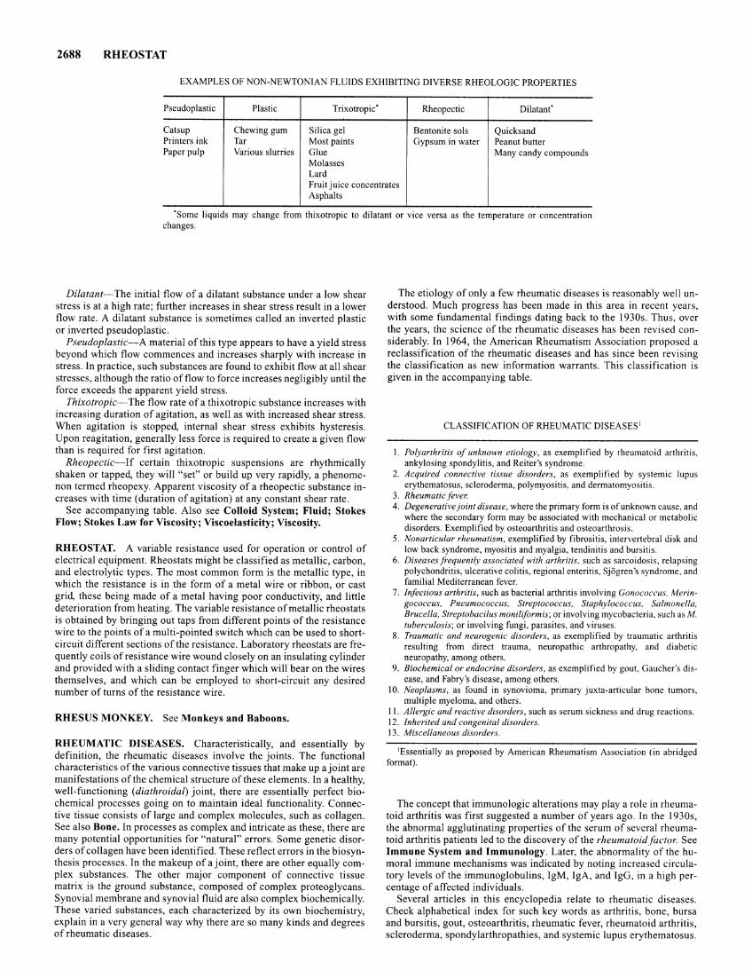
2688 RHEOSTAT
EXAMPLES OF NON-NEWTONIAN FLUIDS EXHIBITING DIVERSE RHEOLOGIC PROPERTIES
Pseudoplastic Plastic Trixotropic" Rheopectic Dilatanf
Catsup Chewing gum Silica gel Bentonite sols Quicksand Printers ink Tar Most paints Gypsum in water Peanut butter Paper pulp Various slurries Glue Many candy compounds
Molasses Lard Fruit juice concentrates Asphalts
"Some liquids may change from thixotropic to dilatant or vice versa as the temperature or concentration changes.
Dilatant-The initial flow of a dilatant substance under a low shear stress is at a high rate; further increases in shear stress result in a lower flow rate. A dilatant substance is sometimes called an inverted plastic or inverted pseudoplastic.
Pseudoplastic-A material of this type appears to have a yield stress beyond which flow commences and increases sharply with increase in stress. In practice, such substances are found to exhibit flow at all shear stresses, although the ratio of flow to force increases negligibly until the force exceeds the apparent yield stress.
Thixotropic-The flow rate of a thixotropic substance increases with increasing duration of agitation, as well as with increased shear stress. When agitation is stopped, internal shear stress exhibits hysteresis. Upon reagitation, generally less force is required to create a given flow than is required for first agitation.
Rheopectic-lf certain thixotropic suspensions are rhythmically shaken or tapped, they will "set" or build up very rapidly, a phenomenon termed rheopexy. Apparent viscosity of a rheopectic substance increases with time (duration of agitation) at any constant shear rate.
See accompanying table. Also see Colloid System; Fluid; Stokes Flow; Stokes Law for Viscosity; Viscoelasticity; Viscosity.
RHEOSTAT. A variable resistance used for operation or control of electrical equipment. Rheostats might be classified as metallic, carbon, and electrolytic types. The most common form is the metallic type, in which the resistance is in the form of a metal wire or ribbon, or cast grid, these being made of a metal having poor conductivity, and little deterioration from heating. The variable resistance of metallic rheostats is obtained by bringing out taps from different points of the resistance wire to the points of a multi-pointed switch which can be used to shortcircuit different sections of the resistance. Laboratory rheostats are frequently coils of resistance wire wound closely on an insulating cylinder and provided with a sliding contact finger which will bear on the wires themselves, and which can be employed to short-circuit any desired number of turns of the resistance wire.
RHESUS MONKEY. See Monkeys and Baboons.
RHEUMATIC DISEASES. Characteristically, and essentially by definition, the rheumatic diseases involve the joints. The functional characteristics of the various connective tissues that make up a joint are manifestations of the chemical structure of these elements. In a healthy, well-functioning (diathroidal) joint, there are essentially perfect biochemical processes going on to maintain ideal functionality. Connective tissue consists of large and complex molecules, such as collagen. See also Bone. In processes as complex and intricate as these, there are many potential opportunities for "natural" errors. Some genetic disorders of collagen have been identified. These reflect errors in the biosynthesis processes. In the makeup of a joint, there are other equally complex substances. The other major component of connective tissue matrix is the ground substance, composed of complex proteoglycans. Synovial membrane and synovial fluid are also complex biochemically. These varied substances, each characterized by its own biochemistry, explain in a very general way why there are so many kinds and degrees of rheumatic diseases.
The etiology of only a few rheumatic diseases is reasonably well understood. Much progress has been made in this area in recent years, with some fundamental findings dating back to the 1930s. Thus, over the years, the science of the rheumatic diseases has been revised considerably. In 1964, the American Rheumatism Association proposed a reclassification of the rheumatic diseases and has since been revising the classification as new information warrants. This classification is given in the accompanying table.
CLASSIFICATION OF RHEUMATIC DISEASES 1
I. Polyarthritis of unknown etiology, as exemplified by rheumatoid arthritis, ankylosing spondylitis, and Reiter's syndrome.
2. Acquired connective tissue disorders, as exemplified by systemic lupus erythematosus, scleroderma, polymyositis, and dermatomyositis.
3. Rheumaticfever. 4. Degenerative joint disease, where the primary form is of unknown cause, and
where the secondary form may be associated with mechanical or metabolic disorders. Exemplified by osteoarthritis and osteoarthrosis.
5. Nonarticular rheumatism, exemplified by fibrositis, intervertebral disk and low back syndrome, myositis and myalgia, tendinitis and bursitis.
6. Diseases frequently associated with arthritis, such as sarcoidosis, relapsing polychondritis, ulcerative colitis, regional enteritis, Sjogren's syndrome, and familial Mediterranean fever.
7. Infectious arthritis, such as bacterial arthritis involving Gonococcus, Meringococcus, Pneumococcus, Streptococcus, Staphylococcus, Salmonella, Brucella, Streptobacilus moniliformis; or involving mycobacteria, such as M. tuberculosis; or involving fungi, parasites, and viruses.
8. Traumatic and neurogenic disorders, as exemplified by traumatic arthritis resulting from direct trauma, neuropathic arthropathy, and diabetic neuropathy, among others.
9. Biochemical or endocrine disorders, as exemplified by gout, Gaucher's disease, and Fabry's disease, among others.
10. Neoplasms, as found in synovioma, primary juxta-articular bone tumors, multiple myeloma, and others.
II. Allergic and reactive disorders, such as serum sickness and drug reactions. 12. Inherited and congenital disorders. 13. Miscellaneous disorders.
1Essentially as proposed by American Rheumatism Association (in abridged format).
The concept that immunologic alterations may play a role in rheumatoid arthritis was first suggested a number of years ago. In the 1930s, the abnormal agglutinating properties of the serum of several rheumatoid arthritis patients led to the discovery of the rheumatoidfactor. See Immune System and Immunology. Later, the abnormality of the humoral immune mechanisms was indicated by noting increased circulatory levels of the immunoglobulins, IgM, IgA, and lgG, in a high percentage of affected individuals.
Several articles in this encyclopedia relate to rheumatic diseases. Check alphabetical index for such key words as arthritis, bone, bursa and bursitis, gout, osteoarthritis, rheumatic fever, rheumatoid arthritis, scleroderma, spondylarthropathies, and systemic lupus erythematosus.
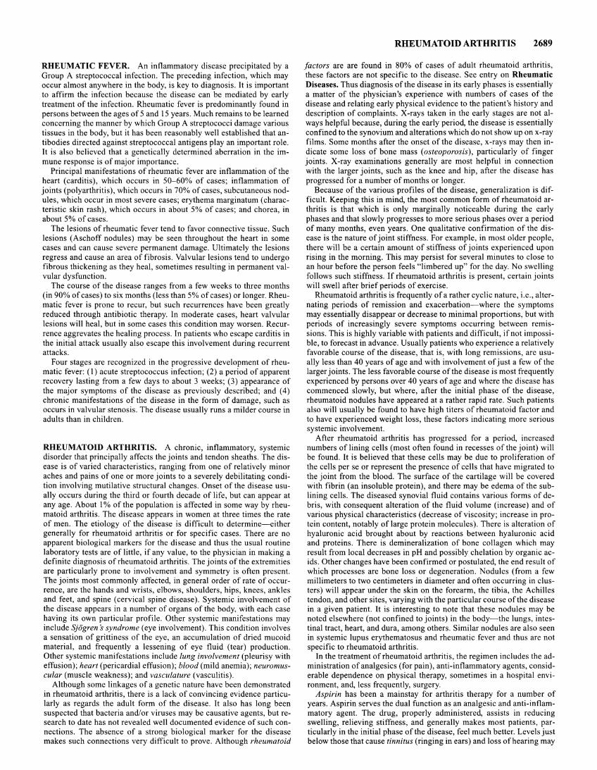
RHEUMATIC FEVER. An inflammatory disease precipitated by a Group A streptococcal infection. The preceding infection, which may occur almost anywhere in the body, is key to diagnosis. It is important to affirm the infection because the disease can be mediated by early treatment of the infection. Rheumatic fever is predominantly found in persons between the ages of 5 and 15 years. Much remains to be learned concerning the manner by which Group A streptococci damage various tissues in the body, but it has been reasonably well established that antibodies directed against streptococcal antigens play an important role. It is also believed that a genetically determined aberration in the immune response is of major importance.
Principal manifestations of rheumatic fever are inflammation of the heart (carditis), which occurs in 50-60% of cases; inflammation of joints (polyarthritis), which occurs in 70% of cases, subcutaneous nodules, which occur in most severe cases; erythema marginatum ( characteristic skin rash), which occurs in about 5% of cases; and chorea, in about 5% of cases.
The lesions of rheumatic fever tend to favor connective tissue. Such lesions (Aschoff nodules) may be seen throughout the heart in some cases and can cause severe permanent damage. Ultimately the lesions regress and cause an area of fibrosis. Valvular lesions tend to undergo fibrous thickening as they heal, sometimes resulting in permanent valvular dysfunction.
The course of the disease ranges from a few weeks to three months (in 90% of cases) to six months (less than 5% of cases) or longer. Rheumatic fever is prone to recur, but such recurrences have been greatly reduced through antibiotic therapy. In moderate cases, heart valvular lesions will heal, but in some cases this condition may worsen. Recurrence aggrevates the healing process. In patients who escape carditis in the initial attack usually also escape this involvement during recurrent attacks.
Four stages are recognized in the progressive development of rheumatic fever: (I) acute streptococcus infection; (2) a period of apparent recovery lasting from a few days to about 3 weeks; (3) appearance of the major symptoms of the disease as previously described; and (4) chronic manifestations of the disease in the form of damage, such as occurs in valvular stenosis. The disease usually runs a milder course in adults than in children.
RHEUMATOID ARTHRITIS. A chronic, inflammatory, systemic disorder that principally affects the joints and tendon sheaths. The disease is of varied characteristics, ranging from one of relatively minor aches and pains of one or more joints to a severely debilitating condition involving mutilative structural changes. Onset of the disease usually occurs during the third or fourth decade of life, but can appear at any age. About 1% of the population is affected in some way by rheumatoid arthritis. The disease appears in women at three times the rate of men. The etiology of the disease is difficult to determine-either generally for rheumatoid arthritis or for specific cases. There are no apparent biological markers for the disease and thus the usual routine laboratory tests are of little, if any value, to the physician in making a definite diagnosis of rheumatoid arthritis. The joints of the extremities are particularly prone to involvement and symmetry is often present. The joints most commonly affected, in general order of rate of occurrence, are the hands and wrists, elbows, shoulders, hips, knees, ankles and feet, and spine (cervical spine disease). Systemic involvement of the disease appears in a number of organs of the body, with each case having its own particular profile. Other systemic manifestations may include Sjogren s syndrome (eye involvement). This condition involves a sensation of grittiness of the eye, an accumulation of dried mucoid material, and frequently a lessening of eye fluid (tear) production. Other systemic manifestations include lung involvement (pleurisy with effusion); heart (pericardia! effusion); blood (mild anemia); neuromuscular (muscle weakness); and vasculature (vasculitis).
Although some linkages of a genetic nature have been demonstrated in rheumatoid arthritis, there is a lack of convincing evidence particularly as regards the adult form of the disease. It also has long been suspected that bacteria and/or viruses may be causative agents, but research to date has not revealed well documented evidence of such connections. The absence of a strong biological marker for the disease makes such connections very difficult to prove. Although rheumatoid
RHEUMATOID ARTHRITIS 2689
factors are are found in 80% of cases of adult rheumatoid arthritis, these factors are not specific to the disease. See entry on Rheumatic Diseases. Thus diagnosis of the disease in its early phases is essentially a matter of the physician's experience with numbers of cases of the disease and relating early physical evidence to the patient's history and description of complaints. X-rays taken in the early stages are not always helpful because, during the early period, the disease is essentially confined to the synovium and alterations which do not show up on x-ray films. Some months after the onset of the disease, x-rays may then indicate some loss of bone mass (osteoporosis), particularly of finger joints. X-ray examinations generally are most helpful in connection with the larger joints, such as the knee and hip, after the disease has progressed for a number of months or longer.
Because of the various profiles of the disease, generalization is difficult. Keeping this in mind, the most common form of rheumatoid arthritis is that which is only marginally noticeable during the early phases and that slowly progresses to more serious phases over a period of many months, even years. One qualitative confirmation of the disease is the nature of joint stiffness. For example, in most older people, there will be a certain amount of stiffness of joints experienced upon rising in the morning. This may persist for several minutes to close to an hour before the person feels "limbered up" for the day. No swelling follows such stiffness. If rheumatoid arthritis is present, certain joints will swell after brief periods of exercise.
Rheumatoid arthritis is frequently of a rather cyclic nature, i.e., alternating periods of remission and exacerbation-where the symptoms may essentially disappear or decrease to minimal proportions, but with periods of increasingly severe symptoms occurring between remissions. This is highly variable with patients and difficult, if not impossible, to forecast in advance. Usually patients who experience a relatively favorable course of the disease, that is, with long remissions, are usually less than 40 years of age and with involvement of just a few of the larger joints. The less favorable course of the disease is most frequently experienced by persons over 40 years of age and where the disease has commenced slowly, but where, after the initial phase of the disease, rheumatoid nodules have appeared at a rather rapid rate. Such patients also will usually be found to have high titers of rheumatoid factor and to have experienced weight loss, these factors indicating more serious systemic involvement.
After rheumatoid arthritis has progressed for a period, increased numbers of lining cells (most often found in recesses of the joint) will be found. It is believed that these cells may be due to proliferation of the cells per se or represent the presence of cells that have migrated to the joint from the blood. The surface of the cartilage will be covered with fibrin (an insoluble protein), and there may be edema of the sublining cells. The diseased synovial fluid contains various forms of debris, with consequent alteration of the fluid volume (increase) and of various physical characteristics (decrease of viscosity; increase in protein content, notably of large protein molecules). There is alteration of hyaluronic acid brought about by reactions between hyaluronic acid and proteins. There is demineralization of bone collagen which may result from local decreases in pH and possibly chelation by organic acids. Other changes have been confirmed or postulated, the end result of which processes are bone loss or degeneration. Nodules (from a few millimeters to two centimeters in diameter and often occurring in clusters) will appear under the skin on the forearm, the tibia, the Achilles tendon, and other sites, varying with the particular course of the disease in a given patient. It is interesting to note that these nodules may be noted elsewhere (not confined to joints) in the body-the lungs, intestinal tract, heart, and dura, among others. Similar nodules are also seen in systemic lupus erythematosus and rheumatic fever and thus are not specific to rheumatoid arthritis.
In the treatment of rheumatoid arthritis, the regimen includes the administration of analgesics (for pain), anti-inflammatory agents, considerable dependence on physical therapy, sometimes in a hospital environment, and, less frequently, surgery.
Aspirin has been a mainstay for arthritis therapy for a number of years. Aspirin serves the dual function as an analgesic and anti-inflammatory agent. The drug, properly administered, assists in reducing swelling, relieving stiffness, and generally makes most patients, particularly in the initial phase of the disease, feel much better. Levels just below those that cause tinnitus (ringing in ears) and loss of hearing may
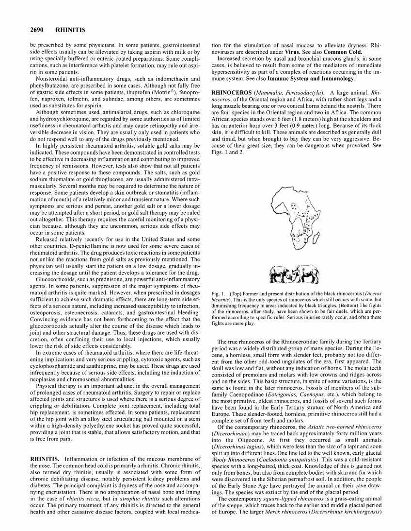
2690 RHINITIS
be prescribed by some physicians. In some patients, gastrointestinal side effects usually can be alleviated by taking aspirin with milk or by using specially buffered or enteric-coated preparations. Some complications, such as interference with platelet formation, may rule out aspirin in some patients.
Nonsteroidal anti-inflammatory drugs, such as indomethacin and phenylbutazone, are prescribed in some cases. Although not fully free of gastric side effects in some patients, ibuprofen (Motrin®), fenoprofen, naproxen, tolmetin, and sulindac, among others, are sometimes used as substitutes for aspirin.
Although sometimes used, antimalarial drugs, such as chloroquine and hydroxychloroquine, are regarded by some authorities as of limited usefulness in rheumatoid arthritis and may cause retinopathy and irreversible decrease in vision. They are usually only used in patients who do not respond well to any of the drugs previously mentioned.
In highly persistent rheumatoid arthritis, soluble gold salts may be indicated. These compounds have been demonstrated in controlled tests to be effective in decreasing inflammation and contributing to improved frequency of remissions. However, tests also show that not all patients have a positive response to these compounds. The salts, such as gold sodium thiomalate or gold thioglucose, are usually administered intramuscularly. Several months may be required to determine the nature of response. Some patients develop a skin outbreak or stomatitis (inflammation of mouth) of a relatively minor and transient nature. Where such symptoms are serious and persist, another gold salt or a lower dosage may be attempted after a short period, or gold salt therapy may be ruled out altogether. This therapy requires the careful monitoring of a physician because, although they are uncommon, serious side effects may occur in some patients.
Released relatively recently for use in the United States and some other countries, D-penicillamine is now used for some severe cases of rheumatoid arthritis. The drug produces toxic reactions in some patients not unlike the reactions from gold salts as previously mentioned. The physician will usually start the patient on a low dosage, gradually increasing the dosage until the patient develops a tolerance for the drug.
Glucocorticoids, such as prednisone, are powerful anti-inflammatory agents. In some patients, suppression of the major symptoms of rheumatoid arthritis is quite marked. However, when prescribed in dosages sufficient to achieve such dramatic effects, there are long-term side effects of a serious nature, including increased susceptibility to infection, osteoporosis, osteonecrosis, cataracts, and gastrointestinal bleeding. Convincing evidence has not been forthcoming to the effect that the glucocorticoids actually alter the course of the disease which leads to joint and other structural damage. Thus, these drugs are used with discretion, often confining their use to local injections, which usually lower the risk of side effects considerably.
In extreme cases of rheumatoid arthritis, where there are life-threatening implications and very serious crippling, cytotoxic agents, such as cyclophosphamide and azathioprine, may be used. These drugs are used infrequently because of serious side effects, including the induction of neoplasias and chromosomal abnormalities.
Physical therapy is an important adjunct in the overall management of prolonged cases of rheumatoid arthritis. Surgery to repair or replace affected joints and structures is used where there is a serious degree of crippling or debilitation. Complete joint replacement, including total hip replacement, is sometimes effected. In some patients, replacement of the hip joint with an alloy steel articulating ball mounted on a stem within a high-density polyethylene socket has proved quite successful, providing a joint that is stable, that allows satisfactory motion, and that is free from pain.
RHINITIS. Inflammation or infection of the mucous membrane of the nose. The common head cold is primarily a rhinitis. Chronic rhinitis, also termed dry rhinitis, usually is associated with some form of chronic debilitating disease, notably persistent kidney problems and diabetes. The principal complaint is dryness of the nose and accompanying encrustation. There is no atrophication of nasal bone and lining in the case of rhinitis sicca, but in atrophic rhinitis such alterations occur. The primary treatment of any rhinitis is directed to the general health and other causative disease factors, coupled with local medica-
tion for the stimulation of nasal mucosa to alleviate dryness. Rhinoviruses are described under Virus. See also Common Cold.
Increased secretion by nasal and bronchial mucous glands, in some cases, is believed to result from some of the mediators of immediate hypersensitivity as part of a complex of reactions occurring in the immune system. See also Immune System and Immunology.
RHINOCEROS (Mammalia, Perissodactyla). A large animal, Rhinoceros, of the Oriental region and Africa, with rather short legs and a long muzzle bearing one or two conical horns behind the nostrils. There are four species in the Oriental region and two in Africa. The common African species stands over 6 feet (1.8 meters) high at the shoulders and has an anterior horn over 3 feet (0.9 meter) long. Because of its thick skin, it is difficult to kill. These animals are described as generally dull and timid, but when brought to bay they can be very aggressive. Because of their great size, they can be dangerous when provoked. See Figs. 1 and 2.
Fig. I. (Top) Former and present distribution of the black rhinocerous (Diceros bicornis). This is the only species of rhinoceros which still occurs with some, but diminishing frequency in areas indicated by black triangles. (Bottom) The fights of the rhinoceros, after study, have been shown to be fair duels, which are performed according to specific rules. Serious injuries rarely occur, and often these fights are mere play.
The true rhinoceros of the Rhinocerotidae family during the Tertiary period was a widely distributed group of many species. During the Eocene, a hornless, small form with slender feet, probably not too different from the other odd-toed ungulates of the era, first appeared. The skull was low and flat, without any indication of horns. The molar teeth consisted of premolars and molars with low crowns and ridges across and on the sides. This basic structure, in spite of some variations, is the same as found in the later rhinoceros. Fossils of members of the subfamily Caenopodinae (Eotrigonias, Caenopus, etc.), which belong to the most primitive, oldest rhinoceros, and fossils of several such forms have been found in the Early Tertiary stratum of North America and Europe. These slender-footed, hornless, primitive rhinoceros still had a complete set of front teeth and molars.
Of the contemporary rhinoceros, the Asiatic two-horned rhinoceros (Dicerorhiniae) may be traced back approximately forty million years into the Oligocene. At first they occurred as small animals (Dicerorhinus tagius), which were less than the size of a tapir and soon split up into different lines. One line led to the well known, early glacial Wooly Rhinoceros (Coelodonta antiquitatis). This was a cold-resistant species with a long-haired, thick coat. Knowledge of this is gained not only from bones, but also from complete bodies with skin and fur which were discovered in the Siberian permafrost soil. In addition, the people of the Early Stone Age have portrayed the animal on their cave drawings. The species was extinct by the end of the glacial period.
The contemporary square-lipped rhinoceros is a grass-eating animal of the steppe, which traces back to the earlier and middle glacial period of Europe. The larger Merck rhinoceros (Dicerorhinus kirchbergensis)
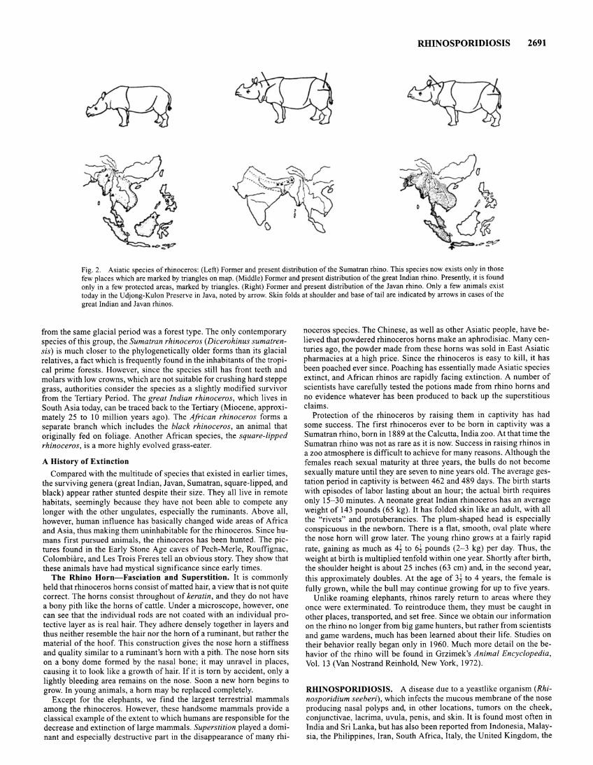
RHINOSPORIDIOSIS 2691
Fig. 2. Asiatic species of rhinoceros: (Left) Former and present distribution of the Sumatran rhino. This species now exists only in those few places which are marked by triangles on map. (Middle) Former and present distribution of the great Indian rhino. Presently, it is found only in a few protected areas, marked by triangles. (Right) Former and present distribution of the Javan rhino. Only a few animals exist today in the Udjong-Kulon Preserve in Java, noted by arrow. Skin folds at shoulder and base of tail are indicated by arrows in cases of the great Indian and Javan rhinos.
from the same glacial period was a forest type. The only contemporary species of this group, the Sumatran rhinoceros (Dicerohinus sumatrensis) is much closer to the phylogenetically older forms than its glacial relatives, a fact which is frequently found in the inhabitants ofthe tropical prime forests. However, since the species still has front teeth and molars with low crowns, which are not suitable for crushing hard steppe grass, authorities consider the species as a slightly modified survivor from the Tertiary Period. The great Indian rhinoceros, which lives in South Asia today, can be traced back to the Tertiary (Miocene, approximately 25 to 10 million years ago) . The African rhinoceros forms a separate branch which includes the black rhinoceros, an animal that originally fed on foliage. Another African species, the square-lipped rhinoceros, is a more highly evolved grass-eater.
A History of Extinction
Compared with the multitude of species that existed in earlier times, the surviving genera (great Indian, Javan, Sumatran, square-lipped, and black) appear rather stunted despite their size. They all live in remote habitats, seemingly because they have not been able to compete any longer with the other ungulates, especially the ruminants. Above all, however, human influence has basically changed wide areas of Africa and Asia, thus making them uninhabitable for the rhinoceros. Since humans first pursued animals, the rhinoceros has been hunted. The pictures found in the Early Stone Age caves of Pech-Merle, Rouffignac, Colombiare, and Les Trois Freres tell an obvious story. They show that these animals have had mystical significance since early times.
The Rhino Horn-Fasciation and Superstition. It is commonly held that rhinoceros horns consist of matted hair, a view that is not quite correct. The horns consist throughout of keratin, and they do not have a bony pith like the horns of cattle . Under a microscope, however, one can see that the individual rods are not coated with an individual protective layer as is real hair. They adhere densely together in layers and thus neither resemble the hair nor the horn of a ruminant, but rather the material of the hoof. This construction gives the nose horn a stiffness and quality similar to a ruminant's horn with a pith. The nose horn sits on a bony dome formed by the nasal bone; it may unravel in places, causing it to look like a growth of hair. If it is torn by accident, only a lightly bleeding area remains on the nose. Soon a new horn begins to grow. In young animals, a horn may be replaced completely.
Except for the elephants, we find the largest terrestrial mammals among the rhinoceros. However, these handsome mammals provide a classical example of the extent to which humans are responsible for the decrease and extinction of large mammals. Superstition played a dominant and especially destructive part in the disappearance of many rhi-
noceros species. The Chinese, as well as other Asiatic people, have believed that powdered rhinoceros horns make an aphrodisiac. Many centuries ago, the powder made from these horns was sold in East Asiatic pharmacies at a high price. Since the rhinoceros is easy to kill, it has been poached ever since. Poaching has essentially made Asiatic species extinct, and African rhinos are rapidly facing extinction. A number of scientists have carefully tested the potions made from rhino horns and no evidence whatever has been produced to back up the superstitious claims.
Protection of the rhinoceros by raising them in captivity has had some success. The first rhinoceros ever to be born in captivity was a Sumatran rhino, born in 1889 at the Calcutta, India zoo. At that time the Sumatran rhino was not as rare as it is now. Success in raising rhinos in a zoo atmosphere is difficult to achieve for many reasons. Although the females reach sexual maturity at three years, the bulls do not become sexually mature until they are seven to nine years old. The average gestation period in captivity is between 462 and 489 days. The birth starts with episodes of labor lasting about an hour; the actual birth requires only 15-30 minutes. A neonate great Indian rhinoceros has an average weight of 143 pounds (65 kg). It has folded skin like an adult, with all the "rivets" and protuberancies. The plum-shaped head is especially conspicuous in the newborn. There is a flat, smooth, oval plate where the nose horn will grow later. The young rhino grows at a fairly rapid rate, gaining as much as 4~ to 6~ pounds (2-3 kg) per day. Thus, the weight at birth is multiplied tenfold within one year. Shortly after birth, the shoulder height is about 25 inches (63 em) and, in the second year, this approximately doubles. At the age of 3j to 4 years, the female is fully grown, while the bull may continue growing for up to five years.
Unlike roaming elephants, rhinos rarely return to areas where they once were exterminated. To reintroduce them, they must be caught in other places, transported, and set free. Since we obtain our information on the rhino no longer from big game hunters, but rather from scientists and game wardens, much has been learned about their life. Studies on their behavior really began only in 1960. Much more detail on the behavior of the rhino will be found in Grzimek 's Animal Encyclopedia, Vol. 13 (Van Nostrand Reinhold, New York, 1972).
RHINOSPORIDIOSIS. A disease due to a yeastlike organism (Rhinosporidium seeberi), which infects the mucous membrane of the nose producing nasal polyps and, in other locations, tumors on the cheek, conjunctivae, lacrima, uvula, penis, and skin. It is found most often in India and Sri Lanka, but has also been reported from Indonesia, Malaysia, the Philippines, Iran, South Africa, Italy, the United Kingdom, the
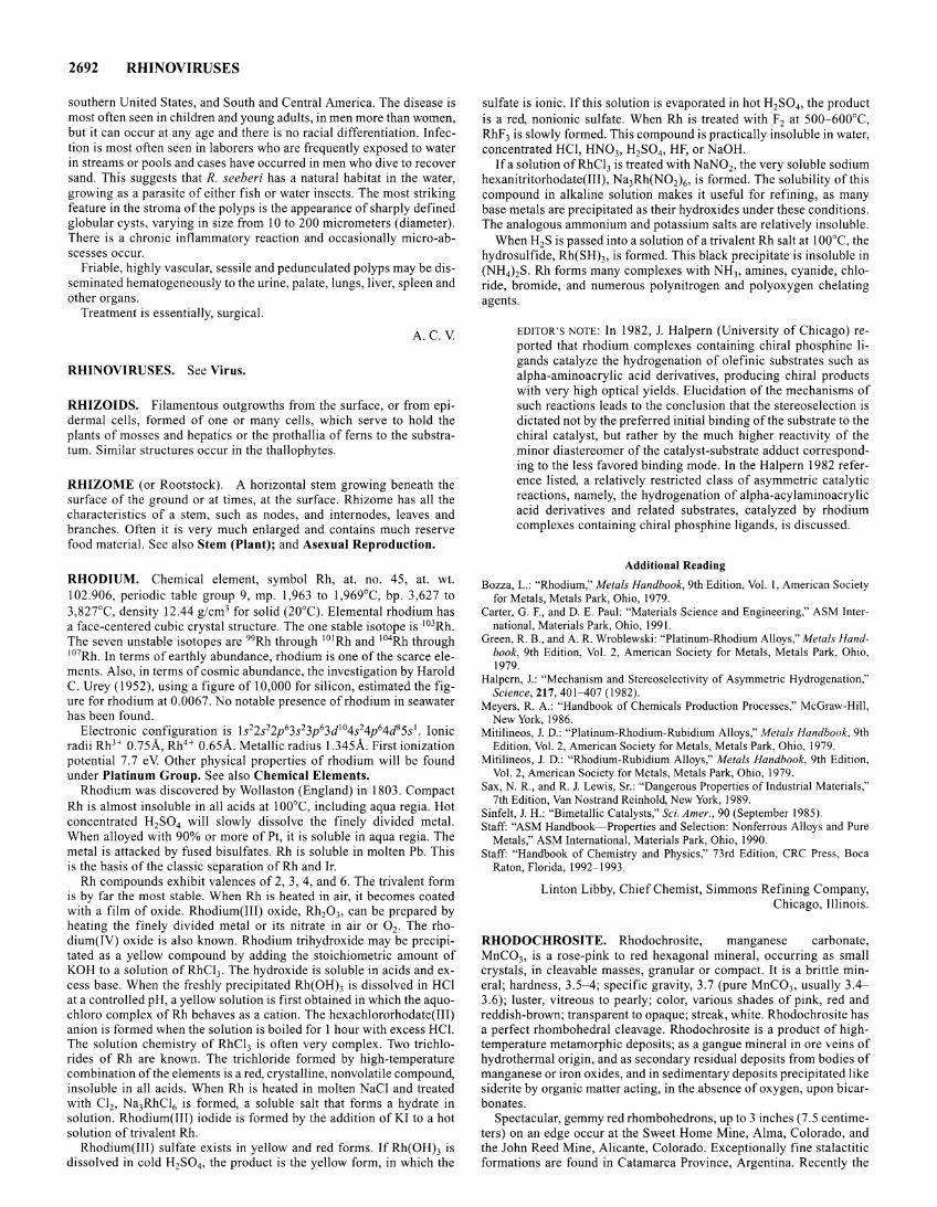
2692 RHINOVIRUSES
southern United States, and South and Central America. The disease is most often seen in children and young adults, in men more than women, but it can occur at any age and there is no racial differentiation. Infection is most often seen in laborers who are frequently exposed to water in streams or pools and cases have occurred in men who dive to recover sand. This suggests that R. seeberi has a natural habitat in the water, growing as a parasite of either fish or water insects. The most striking feature in the stroma of the polyps is the appearance of sharply defined globular cysts, varying in size from 10 to 200 micrometers (diameter). There is a chronic inflammatory reaction and occasionally micro-abscesses occur.
Friable, highly vascular, sessile and pedunculated polyps may be disseminated hematogeneously to the urine, palate, lungs, liver, spleen and other organs.
Treatment is essentially, surgical.
A.C.V.
RHINOVIRUSES. See Virus.
RHIZOIDS. Filamentous outgrowths from the surface, or from epidermal cells, formed of one or many cells, which serve to hold the plants of mosses and hepatics or the prothallia of ferns to the substratum. Similar structures occur in the thallophytes.
RHIZOME (or Rootstock). A horizontal stem growing beneath the surface of the ground or at times, at the surface. Rhizome has all the characteristics of a stem, such as nodes, and internodes, leaves and branches. Often it is very much enlarged and contains much reserve food material. See also Stem (Plant); and Asexual Reproduction.
RHODIUM. Chemical element, symbol Rh, at. no. 45, at. wt. 102.906, periodic table group 9, mp. 1,963 to 1 ,969°C, bp. 3,627 to 3,82rc, density 12.44 g/cm3 for solid (20°C). Elemental rhodium has a face-centered cubic crystal structure. The one stable isotope is 103Rh. The seven unstable isotopes are 99Rh through 101 Rh and 104Rh through 107Rh. In terms of earthly abundance, rhodium is one ofthe scarce elements. Also, in terms of cosmic abundance, the investigation by Harold C. Urey ( 1952), using a figure of 10,000 for silicon, estimated the figure for rhodium at 0.0067. No notable presence of rhodium in seawater has been found.
Electronic configuration is 1 s22s22p63s23p63d104s24p64d85s 1• Ionic radii RhH 0.75A, Rh4 + 0.65A. Metallic radius 1.345A. First ionization potential 7.7 eV. Other physical properties of rhodium will be found under Platinum Group. See also Chemical Elements.
Rhodium was discovered by Wollaston (England) in 1803. Compact Rh is almost insoluble in all acids at I 00°C, including aqua regia. Hot concentrated H2S04 will slowly dissolve the finely divided metal. When alloyed with 90% or more of Pt, it is soluble in aqua regia. The metal is attacked by fused bisulfates. Rh is soluble in molten Pb. This is the basis of the classic separation of Rh and Ir.
Rh compounds exhibit valences of 2, 3, 4, and 6. The trivalent form is by far the most stable. When Rh is heated in air, it becomes coated with a film of oxide. Rhodium(III) oxide, Rh20 3, can be prepared by heating the finely divided metal or its nitrate in air or 0 2. The rhodium(IV) oxide is also known. Rhodium trihydroxide may be precipitated as a yellow compound by adding the stoichiometric amount of KOH to a solution of RhC13. The hydroxide is soluble in acids and excess base. When the freshly precipitated Rh(OH)3 is dissolved in HCl at a controlled pH, a yellow solution is first obtained in which the aquochloro complex of Rh behaves as a cation. The hexachlororhodate(III) anion is formed when the solution is boiled for I hour with excess HC!. The solution chemistry of RhC13 is often very complex. Two trichlorides of Rh are known. The trichloride formed by high-temperature combination of the elements is a red, crystalline, nonvolatile compound, insoluble in all acids. When Rh is heated in molten NaCl and treated with Cl2, Na3RhC16 is formed, a soluble salt that forms a hydrate in solution. Rhodium( III) iodide is formed by the addition of KI to a hot solution of trivalent Rh.
Rhodium(III) sulfate exists in yellow and red forms. If Rh(OH)3 is dissolved in cold H2S04 , the product is the yellow form, in which the
sulfate is ionic. Ifthis solution is evaporated in hot H2S04, the product is a red, nonionic sulfate. When Rh is treated with F2 at 500-600°C, RhF3 is slowly formed. This compound is practically insoluble in water, concentrated HCl, HN03, H2S04, HF, or NaOH.
If a solution ofRhC13 is treated with NaN02, the very soluble sodium hexanitritorhodate(III), Na3Rh(N02) 6 , is formed. The solubility of this compound in alkaline solution makes it useful for refining, as many base metals are precipitated as their hydroxides under these conditions. The analogous ammonium and potassium salts are relatively insoluble.
When H2S is passed into a solution of a trivalent Rh salt at I 00°C, the hydrosulfide, Rh(SH)3, is formed. This black precipitate is insoluble in (NH4hS. Rh forms many complexes with NH3 , amines, cyanide, chloride, bromide, and numerous polynitrogen and polyoxygen chelating agents.
EDITOR'S NOTE: In 1982, J. Halpern (University of Chicago) reported that rhodium complexes containing chiral phosphine ligands catalyze the hydrogenation of olefinic substrates such as alpha-aminoacrylic acid derivatives, producing chiral products with very high optical yields. Elucidation of the mechanisms of such reactions leads to the conclusion that the stereoselection is dictated not by the preferred initial binding of the substrate to the chiral catalyst, but rather by the much higher reactivity of the minor diastereomer of the catalyst-substrate adduct corresponding to the less favored binding mode. In the Halpern 1982 reference listed, a relatively restricted class of asymmetric catalytic reactions, namely, the hydrogenation of alpha-acylaminoacrylic acid derivatives and related substrates, catalyzed by rhodium complexes containing chiral phosphine ligands, is discussed.
Additional Reading
Bozza, L.: "Rhodium," Metals Handbook, 9th Edition, Vol. I, American Society for Metals, Metals Park, Ohio, 1979.
Carter, G. F., and D. E. Paul: "Materials Science and Engineering," ASM International, Materials Park, Ohio, 1991.
Green, R. B., and A. R. Wroblewski: "Platinum-Rhodium Alloys," Metals Handbook, 9th Edition, Vol. 2, American Society for Metals, Metals Park, Ohio, 1979.
Halpern, J.: "Mechanism and Stereoselectivity of Asymmetric Hydrogenation," Science, 217,401-407 (1982).
Meyers, R. A.: "Handbook of Chemicals Production Processes," McGraw-Hill, New York, 1986.
Mitilineos, J. D.: "Platinum-Rhodium-Rubidium Alloys," Metals Handbook, 9th Edition, Vol. 2, American Society for Metals, Metals Park, Ohio, 1979.
Mitilineos, J. D.: "Rhodium-Rubidium Alloys," Metals Handbook, 9th Edition, Vol. 2, American Society for Metals, Metals Park, Ohio, 1979.
Sax, N. R., and R. J. Lewis, Sr.: "Dangerous Properties of Industrial Materials," 7th Edition, Van Nostrand Reinhold, New York, 1989.
Sinfelt, J. H.: "Bimetallic Catalysts," Sci. Amer., 90 (September 1985). Staff: "ASM Handbook-Properties and Selection: Nonferrous Alloys and Pure
Metals," ASM International, Materials Park, Ohio, 1990. Staff: "Handbook of Chemistry and Physics," 73rd Edition, CRC Press, Boca
Raton, Florida, 1992-1993.
Linton Libby, Chief Chemist, Simmons Refining Company, Chicago, Illinois.
RHODOCHROSITE. Rhodochrosite, manganese carbonate, MnC03, is a rose-pink to red hexagonal mineral, occurring as small crystals, in cleavable masses, granular or compact. It is a brittle mineral; hardness, 3.5-4; specific gravity, 3.7 (pure MnC03, usually 3.4-3.6); luster, vitreous to pearly; color, various shades of pink, red and reddish-brown; transparent to opaque; streak, white. Rhodochrosite has a perfect rhombohedral cleavage. Rhodochrosite is a product of hightemperature metamorphic deposits; as a gangue mineral in ore veins of hydrothermal origin, and as secondary residual deposits from bodies of manganese or iron oxides, and in sedimentary deposits precipitated like siderite by organic matter acting, in the absence of oxygen, upon bicarbonates.
Spectacular, gemmy red rhombohedrons, up to 3 inches (7 .5 centimeters) on an edge occur at the Sweet Home Mine, Alma, Colorado, and the John Reed Mine, Alicante, Colorado. Exceptionally fine stalactitic formations are found in Catamarca Province, Argentina. Recently the
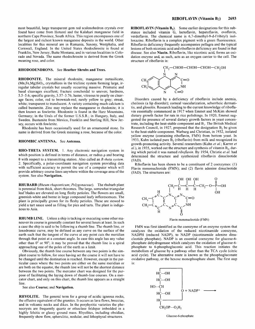
most beautiful, large transparent gem red scalenohedron crystals ever found have come from Hotazel and the Kalahari manganese field in northern Cape Province, South Africa. This region encompasses one of the largest and richest known manganese deposits in the world. Other localities for this mineral are in Rumania, Saxony, Westphalia, and Cornwall, England. In the United States rhodochrosite is found at Franklin, New Jersey; Butte Montana; and in various localities in Colorado and Nevada. The name rhodochrosite is derived from the Greek meaning rose, and color.
RHODODENDRONS. See Heather Shrubs and Trees.
RHODONITE. The mineral rhodonite, manganese metasilicate, (Mn,Fe,Mg)Si03, crystallizes in the triclinic system forming large, irregular tabular crystals but usually occurring massive. Prismatic and basal cleavages excellent; fracture conchoidal to uneven; hardness, 5.5-5.6; specific gravity, 3.57-3.76; luster, vitreous to pearly on cleavage faces; color, red to brownish-red; rarely yellow to gray; streak, white; transparent to translucent. A variety containing much calcium is called bustamite. Zinc may replace the manganese in rhodonite; it is then known as fowlerite. Rhodonite is found in the Harz Mountains, Germany; in the Urals of the former U.S.S.R.; in Hungary, Italy, and Sweden. Bustamite from Mexico, Franklin and Sterling Hill, New Jersey, occurs with fowlerite.
Rhodonite has been occasionally used for an ornamental stone. Its name is derived from the Greek meaning a rose, because of the color.
RHOMBIC ANTENNA. See Antenna.
RHO-THETA SYSTEM. I. Any electronic navigation system in which position is defined in terms of distance, or radius p and bearing e with respect to a transmitting station. Also called an R-theta system. 2. Specifically, a polar-coordinate navigation system providing data with sufficient accuracy to permit the use of a computer which will provide arbitrary course lines anywhere within the coverage area of the system. See also Navigation.
RHUBARB (Rheum rhaponticum; Polygonaceae). The rhubarb plant is perennial from thick, short rhizomes. The large, somewhat triangular leaf blades are elevated on long fleshy petioles. The flowers are small, greenish-white and borne in large compound leafy inflorescences. The plant is principally grown for its fleshy petioles. These are stewed to yield a tart sauce used as filling for pies and tarts. The plant is indigenous to Asia.
RHUMB LINE. Unless a ship is tacking or executing some other maneuver its course is generally constant for several hours at least. In such a case the ship is said to be following a rhumb line. The rhumb line, or loxodromic curve, may be defined as any curve on the surface of the earth such that the tangent of the curve at any point cuts the meridian through that point at a constant angle. In case this angle has any value other than 0° or 90°; it may be proved that the rhumb line is a spiral approaching one of the poles of the earth as a limit.
Obviously, the rhumb line course between any two points is the simplest course to follow, for once having set the course it will not have to be changed until the destination is reached. However, except in the particular cases where the two points are either on the same meridian or are both on the equator, the rhumb line will not be the shortest distance between the two points. The mercator chart was designed for the purpose of facilitating the laying down of rhumb-line courses. On a mercator chart, and only on this chart, the rhumb line appears as a straight line.
See also Course; and Navigation.
RHYOLITE. The general term for a group of acidic igneous rocks, the effusive equivalent of the granites. It occurs as lava flows, breccias, and in volcanic necks and dikes. In the porphyritic varieties the phenocrysts are frequently quartz or othoclase feldspar imbedded in a highly felsitic or glassy ground mass. Rhyolites, including obsidian, frequently show flow, spherulitic, nodular, and lithophysal structures.
RIBOFLAVIN (Vitamin B2) 2693
RIBOFLAVIN (Vitamin B2). Some earlier designations for this substance included vitamin G, lactoflavin, hepatoflavin, ovoflavin, verdoflavin. The chemical name is 6,7-dimethyl-9-d-l'ribityl) isolloxazine. Riboflavin is a complex pigment with a green fluorescence. Riboflavin deficiency frequently accompanies pellagra and the typical lesions of both nicotinic acid and riboflavin deficiency are found in that disease. See also Niacin. Riboflavin, like nicotinic acid, forms an oxidation enzyme and, as such, acts as an oxygen carrier to the cell. The structure of riboflavin is:
CH2-CHOH-CHOH-CHOH-CHpH I
N N
3 I I CH cxxr' C=O
CH3 ~ 0 NH
N C=O
Disorders caused by a deficiency of riboflavin include anemia, cheilosis (a lip disorder); corneal vascularization, seborrheic dermatitis, and glossitis. Research leading to the current knowledge of riboflavin essentially commenced in 1917 when Emmet and McKim showed dietary growth factor for rats in rice polishings. In 1920, Emmet suggested the presence of several dietary growth factors in yeast concentrate, including the heat-stable component and B 1• The British Medical Research Council, in 1927, proposed that the designation B2 be given to the heat-stable component. Warburg and Christian, in 1932, isolated yellow enzyme (containing riboflavin, FMN) from bottom yeast. In 1933, Kuhn isolated pure B2 (riboflavin) from milk and recognized its growth-promoting activity. Several researchers (Kuhn eta!.; Karrer et a!.), in 1935, worked out the structure and synthesis of vitamin B2, during which period it was named riboflavin. By 1954, Christie et al. had determined the structure and synthesized riboflavin dinucleotide (FAD).
Riboflavin has been shown to be a constituent of 2 coenzymes: (l) Flavin mononucleotide (FMN); and (2) flavin adenine dinucleotide (FAD). The structures are:
OH OH OH 0 I I I II
CH -C-C-C-CH- 0-P-OH 1
2 HHH 2 I H OH
~C, _...N, ~N, CH-C C C C=O
3 I II I I CH3-C,.... _...C, ~C, _...NH
"c N c H II
0
Flavin mononucleotide (FMN)
FMN was first identified as the coenzyme of an enzyme system that catalyzes the oxidation of the reduced nicotinamide coenzyme, NADPH (reduced NADP), to NADP (nicotinamide adenine dinucleotide phosphate). NADP is an essential coenzyme for glucose-6-phosphate dehydrogenase which catalyzes the oxidation of glucose-6-phosphate to 6-phosphogluconic acid. This reaction initiates the metabolism of glucose by a pathway other than the TCA cycle (citric acid cycle). The alternative route is known as the phosphogluconate oxidative pathway, or the hexose monophosphate shunt. The first step is:
HCDlOH HC~OH
I HO~CH
I 0 + NADP+ HT~OH I HC------'·
I CHpP~03H2
Glucose-6-phosphate
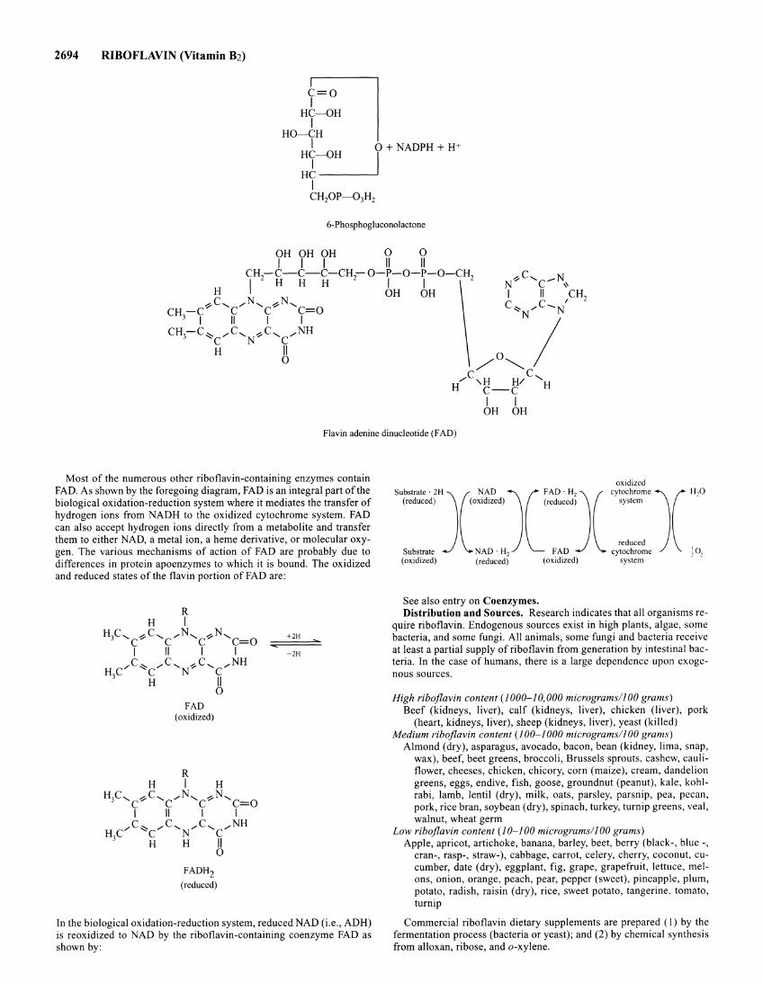
2694 RIBOFLAVIN (Vitamin Bz)
H?-OH
HO-CH Fl Ht-OH 0 + NADPH + H+
Ht I I CH20P-03H2
6-Phosphogluconolactone
OH OH OH 0 0 I I I II II
CH -C-C-C-CH-0-P-0-P-0-CH 1
2 HHH 2 I I 2
H OH OH ~C, _....N, ~N,
CH-C C C C=O 3 I II I I
CH3-C ~ _....C, ~C, _....NH "'c N c
H II 0
Flavin adenine dinucleotide (FAD)
Most of the numerous other riboflavin-containing enzymes contain FAD. As shown by the foregoing diagram, FAD is an integral part of the biological oxidation-reduction system where it mediates the transfer of hydrogen ions from NADH to the oxidized cytochrome system. FAD can also accept hydrogen ions directly from a metabolite and transfer them to either NAD, a metal ion, a heme derivative, or molecular oxygen. The various mechanisms of action of FAD are probably due to differences in protein apoenzymes to which it is bound. The oxidized and reduced states of the flavin portion of FAD are:
R H I
H3C, ~C, _....N, ~N, C C C C=O I II I I
,C ~ _....C, ..., C, _....NH H C' "'c N" C
3 H II
FAD (oxidized)
R
0
H I H H3C, ~C, _....N, ~N,
C C C C=O I II I I
_....c~ _....c, ,....c, _....NH H3C "'c N C
H H II 0
FADHz
(reduced)
+2H
-2H
In the biological oxidation-reduction system, reduced NAD (i.e., ADH) is reoxidized to NAD by the riboflavin-containing coenzyme FAD as shown by:
oxidized
s~~::Jc:D~JC~~~~)( ::::: j( HOD
(oxidized) (reduced) (oxidized) system · •
See also entry on Coenzymes. Distribution and Sources. Research indicates that all organisms re
quire riboflavin. Endogenous sources exist in high plants, algae, some bacteria, and some fungi. All animals, some fungi and bacteria receive at least a partial supply of riboflavin from generation by intestinal bacteria. In the case of humans, there is a large dependence upon exogenous sources.
High riboflavin content (1000-10,000 micrograms/100 grams) Beef (kidneys, liver), calf (kidneys, liver), chicken (liver), pork
(heart, kidneys, liver), sheep (kidneys, liver), yeast (killed) Medium riboflavin content (100-1000 micrograms/100 grams)
Almond (dry), asparagus, avocado, bacon, bean (kidney, lima, snap, wax), beef, beet greens, broccoli, Brussels sprouts, cashew, cauliflower, cheeses, chicken, chicory, corn (maize), cream, dandelion greens, eggs, endive, fish, goose, groundnut (peanut), kale, kohlrabi, lamb, lentil (dry), milk, oats, parsley, parsnip, pea, pecan, pork, rice bran, soybean (dry), spinach, turkey, turnip greens, veal, walnut, wheat germ
Low riboflavin content (1 0-100 micrograms/] 00 grams) Apple, apricot, artichoke, banana, barley, beet, berry (black-, blue-,
cran-, rasp-, straw-), cabbage, carrot, celery, cherry, coconut, cucumber, date (dry), eggplant, fig, grape, grapefruit, lettuce, melons, onion, orange, peach, pear, pepper (sweet), pineapple, plum, potato, radish, raisin (dry), rice, sweet potato, tangerine. tomato, turnip
Commercial riboflavin dietary supplements are prepared (I) by the fermentation process (bacteria or yeast); and (2) by chemical synthesis from alloxan, ribose, and a-xylene.
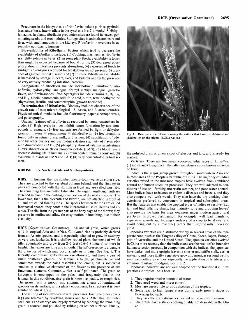
Precursors in the biosynthesis of riboflavin include purines, pyrimidines, and ribose . Intermediate in the synthesis is 6,7-dimethyl-8-ribityllumazine. In plants, riboflavin production sites are found in leaves, germinating seeds, and root nodules. Storage sites in animals are heart and liver, with small amounts in the kidneys. Riboflavin in overdose is essentially nontoxic to humans.
Bioavailability of Riboflavin. Factors which tend to decrease the availability of riboflavin include: ( 1) Cooking, inasmuch as riboflavin is slightly soluble in water; (2) in some plant foods, availability is lower than might be expected because of bound forms; (3) decreased phosphorylation in intestines prevents absorption; ( 4) exposure of foods to sunlight; (5) enzymes required for breakdown are not present; (6) presence of gastrointestinal disease; and (7) diuresis. Riboflavin availability is increased by storage in heart, liver, and kidneys and by the presence of very actively producing intestinal bacteria.
Antagonists of riboflavin include isoriboflavin, lumiflavin, araboflavin, hydroxyethyl analogue, formyl methyl analogue, galactoflavin, and flavin-monosulfate. Synergists include vitamins A, B1, B6,
and B12, niacin, pantothenic acid, folic acid, biotin, tetraiodothyronine (thyroxine), insulin, and somatotrophin (growth hormone).
Determination of Riboflavin. Bioassay includes observance of the growth rate of rats; microbiological-L. caseli, and L. mesenteroides. Physicochemical methods include fluorimetry, paper electrophoresis, and polarography.
Unusual features of riboflavin as recorded by some researchers include: (1) High levels in liver inhibit tumor formation by azo compounds in animals; (2) free radicals are formed by light or dehydrogenation: flavine :;:= semiquinone :;:= dihydroflavin; (3) free vitamin is found only in retina, urine, milk, and semen; (4) substitution of adenine by other purines and pyrimidines destroys activity of flavin adenine dinucleotide (FAD); (5) phosphorylation of vitamin in intestines allows absorption as flavin mononucleotide (FMN); (6) blood levels decrease during life in humans: (7) brain content remains constant; (8) available in plants as FMN and FAD; (8) very concentrated in bull semen.
RIBOSE. See Nucleic Acids and Nucleoproteins.
RIBS. In humans, the ribs number twenty-four, twelve on either side. They are attached to the vertebral column behind, and the first seven pairs are connected with the sternum in front and are called true ribs. The remaining five are called false ribs. The eighth, ninth and tenth are attached in front to the cartilaginous portion of the next rib above. The lower two, that is the eleventh and twelfth, are not attached in front at all and are called floating ribs. The spaces between the ribs are called intercostal spaces; they contain the intercostal muscles, nerves and arteries. The ribs form the greater part ofthe bony cage ofthe thorax; they preserve its outline and allow for easy motion in breathing, due to their elasticity.
RICE (Oryza sativa; Gramineae). An annual grass, which grows wild in tropical Asia and Africa. Cultivated rice is probably derived from an Asiatic species, and is especially adapted to grow in swampy or very wet lowlands. It is a shallow rooted plant, the stems of which tiller abundantly and grow from 2-6 feet (0.6-1.8 meters) or more in height. The leaves are long and smooth. The inflorescence is a panicle the branches of which may occur singly or in pairs. See Fig. I. The laterally compressed spikelets are one-flowered, and have a pair of small bristlelike glumes; the lemma is tough, parchment-like and sometimes awned; the palea resembles the lemma, but is somewhat smaller. A distinctive character of the flower is the presence of six functional stamens. Commonly, rice is self-pollinated. The grain or karyopsis is enwrapped in the palea, and frequently also in the lemma. In this condition, rice grain is known as paddy, or rough rice. The grain itself is smooth and shining, has a pair of longitudinal grooves on its surface, and a glassy endosperm. In structure it is very similar to wheat grain.
The milling of rice involves several processes. First, the outer coverings are removed by revolving stones and fans . After this, the outer seed-coats and embryo are largely removed by rubbing; the remaining grain is scoured and polished by rubbing on leather surfaces. Finally,
RICE (Oryza sativa; Gramineae) 2695
Fig. 1. Rice panicle in bloom showing the anthers that have just dehisced and shed pollen on the stigma. (USDA photo.)
the polished grain is given a coat of glucose and talc, and is ready for market.
Varieties. There are two major eco-geographic races of 0. sativa: (I) indica and (2) japonica. The latter sometimes also is known as sinica or keng.
Indica is the major group grown throughout southeastern Asia and in most areas of the People's Republic of China. The majority of indica varieties raised in the monsoon tropics have evolved from combined natural and human selection processes. They are well adapted to conditions of low-soil fertility, uncertain weather, and poor water control. Most indicas have resistance to endemic diseases and insects, and they also compete well with weeds. They also have the dry cooking characteristics preferred by consumers in tropical and subtropical areas. But the features that enable the tropical types of indica to survive (i.e., tall and high tillering plants, late maturity, long and drooping leaves) also provide the basis for their weakness under modern agricultural practices. Improved fertilization, for example, will lead mainly to vegetative growth and lodging (tendency of a crop to bend over and avoid being cut by a machine) rather than significantly increased yield.
Japonica varieties are distributed widely in several areas of the temperate zone, such as the Yangtze valley of China, Korea, Japan, Europe, part of Australia, and the United States. The japonica varieties evolved in China more recently than the indicas and are the result of an intensive human selection process. In comparison with the indicas, the japonicas have darker and more upright leaves, a shorter and stiffer stalk, earlier maturity, and more thrifty vegetative growth. Japonicas respond well to improved cultural practices, especially the application of fertilizer, and are more resistant to lodging. See Fig. 2.
Japonicas, however, are not well adapted for the traditional cultural practices in tropical Asia because:
I. They require precise amounts of water. 2. They need weed and insect control. 3. Most are susceptible to virus diseases of the tropics. 4. Some react to high temperatures during early growth stages by
flowering too early. 5. They lack the grain dormancy needed in the monsoon season. 6. The grains have a sticky cooking quality not desirable in the Ori
ent.
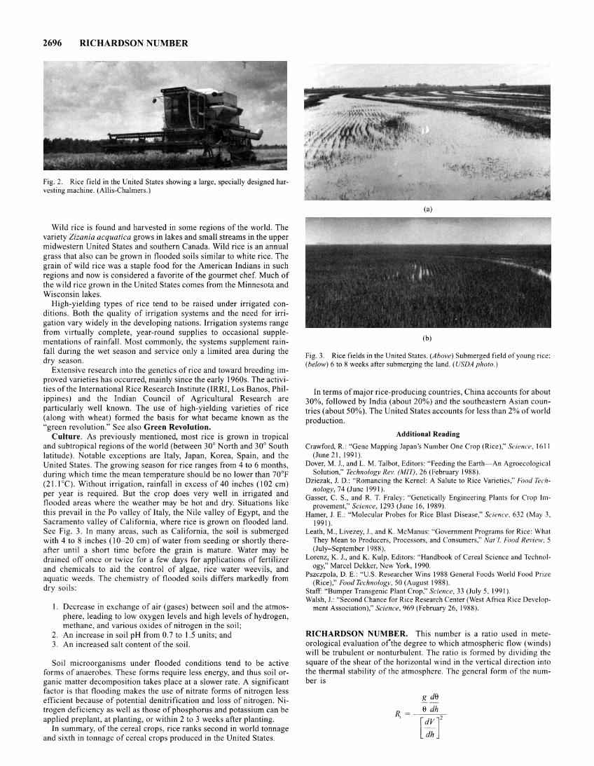
2696 RICHARDSON NUMBER
Fig. 2. Rice field in the United States showing a large, specially designed harvesting machine. (Allis-Chalmers.)
Wild rice is found and harvested in some regions of the world. The variety Zizania acquatica grows in lakes and small streams in the upper midwestern United States and southern Canada. Wild rice is an annual grass that also can be grown in flooded soils similar to white rice. The grain of wild rice was a staple food for the American Indians in such regions and now is considered a favorite of the gourmet chef. Much of the wild rice grown in the United States comes from the Minnesota and Wisconsin lakes.
High-yielding types of rice tend to be raised under irrigated conditions. Both the quality of irrigation systems and the need for irrigation vary widely in the developing nations. Irrigation systems range from virtually complete, year-round supplies to occasional supplementations of rainfall. Most commonly, the systems supplement rainfall during the wet season and service only a limited area during the dry season.
Extensive research into the genetics of rice and toward breeding improved varieties has occurred, mainly since the early 1960s. The activities of the International Rice Research Institute (IRRI, Los Banos, Philippines) and the Indian Council of Agricultural Research are particularly well known. The use of high-yielding varieties of rice (along with wheat) formed the basis for what became known as the "green revolution." See also Green Revolution.
Culture. As previously mentioned, most rice is grown in tropical and subtropical regions of the world (between 30° North and 30° South latitude). Notable exceptions are Italy, Japan, Korea, Spain, and the United States. The growing season for rice ranges from 4 to 6 months, during which time the mean temperature should be no lower than 70°F (21.1 °C). Without irrigation, rainfall in excess of 40 inches (102 em) per year is required. But the crop does very well in irrigated and flooded areas where the weather may be hot and dry. Situations like this prevail in the Po valley of Italy, the Nile valley of Egypt, and the Sacramento valley of California, where rice is grown on flooded land. See Fig. 3. In many areas, such as California, the soil is submerged with 4 to 8 inches (I 0-20 em) of water from seeding or shortly thereafter until a short time before the grain is mature. Water may be drained off once or twice for a few days for applications of fertilizer and chemicals to aid the control of algae, rice water weevils, and aquatic weeds. The chemistry of flooded soils differs markedly from dry soils:
I . Decrease in exchange of air (gases) between soil and the atmosphere, leading to low oxygen levels and high levels of hydrogen, methane, and various oxides of nitrogen in the soil;
2. An increase in soil pH from 0.7 to 1.5 units; and 3. An increased salt content of the soil.
Soil microorganisms under flooded conditions tend to be active forms of anaerobes. These forms require less energy, and thus soil organic matter decomposition takes place at a slower rate. A significant factor is that flooding makes the use of nitrate forms of nitrogen less efficient because of potential denitrification and loss of nitrogen. Nitrogen defic iency as well as those of phosphorus and potassium can be applied preplan!, at planting, or within 2 to 3 weeks after planting.
In summary, of the cereal crops, rice ranks second in world tonnage and sixth in tonnage of cereal crops produced in the United States.
(a)
(b)
Fig. 3. Rice fields in the United States. (Above) Submerged field of young rice; (below) 6 to 8 weeks after submerging the land. (USDA photo.)
In terms of major rice-producing countries, China accounts for about 30%, followed by India (about 20%) and the southeastern Asian countries (about 50%). The United States accounts for less than 2% of world production.
Additional Reading
Crawford, R.: "Gene Mapping Japan's Number One Crop (Rice)," Science, 1611 (June 21, 1991).
Dover, M. J. , and L. M. Talbot, Editors: "Feeding the Earth- An Agroecological Solution," Technology Rev. (MIT), 26 (February 1988).
Dziezak, J. D.: "Romancing the Kernel: A Salute to Rice Varieties," Food Technology, 74 (June 1991).
Gasser, C. S., and R. T. Fraley: "Genetically Engineering Plants for Crop Improvement," Science, 1293 (June 16, 1989).
Hamer, J. E.: "Molecular Probes for Rice Blast Disease," Science, 632 (May 3, 1991).
Leath, M., Livezey, J. , and K. McManus: "Government Programs for Rice: What They Mean to Producers, Processors, and Consumers," Nat '/. Food Review, 5 (July-September 1988).
Lorenz, K. J., and K. Kulp, Editors: "Handbook of Cereal Science and Technology," Marcel Dekker, New York, 1990.
Pszczpola, D. E.: "U.S. Researcher Wins 1988 General Foods World Food Prize (Rice)," Food Technology, 50 (August 1988).
Staff: "Bumper Transgenic Plant Crop," Science, 33 (July 5, 1991 ). Walsh, J.: "Second Chance for Rice Research Center (West Africa Rice Develop
ment Association)," Science, 969 (February 26, 1988).
RICHARDSON NUMBER. This number is a ratio used in meteorological evaluation ofthe degree to which atmospheric flow (winds) will be trubulent or nonturbulent. The ratio is formed by dividing the square of the shear of the horizontal wind in the vertical direction into the thermal stability of the atmosphere. The general form of the number is
g de
e dh R, = - ---:,-[:r
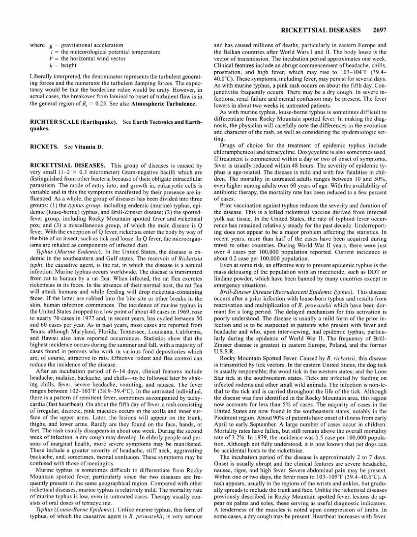
where g = gravitational acceleration i = the meteorological potential temperature
V = the horizontal wind vector h = height
Liberally interpreted, the denominator represents the turbulent generating forces and the numerator the turbulent damping forces. The expectancy would be that the borderline value would be unity. However, in actual cases, the breakover from lamina! to onset of turbulent flow is in the general region of R, = 0.25. See also Atmospheric Turbulence.
RICHTER SCALE (Earthquake). See Earth Tectonics and Earthquakes.
RICKETS. See Vitamin D.
RICKETTSIAL DISEASES. This group of diseases is caused by very small ( 1-2 X 0.3 micrometer) Gram-negative bacilli which are distinguished from other bacteria because of their obligate intracellular parasitism. The mode of entry into, and growth in, eukaryotic cells is variable and in this the symptoms manifested by their presence are influenced. As a whole, the group of diseases has been divided into three groups: (I) the typhus group, including endemic (murine) typhus, epidemic (louse-borne) typhus, and Brill-Zinsser disease; (2) the spottedfever group, including Rocky Mountain spotted fever and rickettsial pox; and (3) a miscellaneous group, of which the main disease is Q fever. With the exception of Q fever, rickettsia enter the body by way of the bite of an insect, such as tick and louse. In Q fever, the microorganisms are inhaled as components of infected dust.
Typhus (Murine Endemic). In the United States, the disease is endemic in the southeastern and Gulf states. The reservoir of Rickettsia typhi, the causative agent, is the rat, in which the disease is a natural infection. Murine typhus occurs worldwide. The disease is transmitted from rat to human by a rat flea. When infected, the rat flea excretes rickettsias in its feces. In the absence of their normal host, the rat flea will attack humans and while feeding will drop rickettsia-containing feces. If the latter are rubbed into the bite site or other breaks in the skin, human infection commences. The incidence of murine typhus in the United States dropped to a low point of about 40 cases in 1969, rose to nearly 70 cases in 1977 and, in recent years, has cycled between 50 and 60 cases per year. As in past years, most cases are reported from Texas, although Maryland, Florida, Tennessee, Louisiana, California, and Hawaii also have reported occurrences. Statistics show that the highest incidence occurs during the summer and fall, with a majority of cases found in persons who work in various food depositories which are, of course," attractive to rats. Effective rodent and flea control can reduce the incidence of the disease.
After an incubation period of 6-14 days, clinical features include headache, malaise, backache, and chills-to be followed later by shaking chills, fever, severe headache, vomiting, and nausea. The fever ranges between I 02-1 03°F (38.9-39.4°C). In the untreated individual, there is a pattern of remittent fever, sometimes accompanied by tachycardia (fast heartbeat). On about the fifth day offever, a rash consisting of irregular, discrete, pink macules occurs in the axilla and inner surface of the upper arms. Later, the lesions will appear on the trunk, thighs, and lower arms. Rarely are they found on the face, hands, or feet. The rash usually dissapears in about one week. During the second week of infection. a dry cough may develop. In elderly people and persons of marginal health, more severe symptoms may be manifested. These include a greater severity of headache, stiff neck, aggravating backache, and, sometimes, mental confusion. These symptoms may be confused with those of meningitis.
Murine typhus is sometimes difficult to differentiate from Rocky Mountain spotted fever, particularly since the two diseases are frequently present in the same geographical region. Compared with other rickettsial diseases, murine typhus is relatively mild. The mortality rate of murine typhus is low, even in untreated cases. Therapy usually consists of oral doses of tetracycline.
Typhus (Louse-Borne Epidemic). Unlike murine typhus, this form of typhus, of which the causative agent is R. prowazekii, is very serious
RICKETTSIAL DISEASES 2697
and has caused millions of deaths, particularly in eastern Europe and the Balkan countries after World Wars I and II. The body louse is the vector of transmission. The incubation period approximates one week. Clinical features include an abrupt commencement of headache, chills, prostration, and high fever, which may rise to 103-104°F (39.4-40.00C). These symptoms, including fever, may persist for several days. As with murine typhus, a pink rash occurs on about the fifth day. Conjunctivitis frequently occurs. There may be a dry cough. In severe infections, renal failure and mental confusion may be present. The fever lowers in about two weeks in untreated patients.
As with murine typhus, louse-borne typhus is sometimes difficult to differentiate from Rocky Mountain spotted fever. In making the diagnosis, the physician will carefully note the differences in the evolution and character of the rash, as well as considering the epidemiologic setting.
Drugs of choice for the treatment of epidemic typhus include chloramphenicol and tetracycline. Doxycycline is also sometimes used. If treatment is commenced within a day or two of onset of symptoms, fever is usually reduced within 48 hours. The severity of epidemic typhus is age-related. The disease is mild and with few fatalities in children. The mortality in untreated adults ranges between I 0 and 50%, even higher among adults over 60 years of age. With the availability of antibiotic therapy, the mortality rate has been reduced to a few percent of cases.
Prior vaccination against typhus reduces the severity and duration of the disease. This is a killed rickettsial vaccine derived from infected yolk sac tissue. In the United States, the rate of typhoid fever occurrence has remained relatively steady for the past decade. Underreporting does not appear to be a major problem affecting the statistics. In recent years, more than half of the cases have been acquired during travel to other countries. During World War II years, there were just over 4 cases per I 00,000 population reported. Current incidence is about 0.2 case per I 00,000 population.
Even at some risk, an effective way to prevent epidemic typhus is the mass delousing of the population with an insecticide, such as DDT or lindane powder, which have been banned by many countries except in emergency situations.
Brill-Zinsser Disease (Recrudescent Epidemic Typhus). This disease occurs after a prior infection with louse-born typhus and results from reactivation and multiplication of R. prowazekii which have been dormant for a long period. The delayed mechanism for this activation is poorly understood. The disease is usually a mild form of the prior infection and is to be suspected in patients who present with fever and headache and who, upon interviewing, had epidemic typhus, particularly during the epidemic of World War II. The frequency of BrillZinsser disease is greatest in eastern Europe, Poland, and the former U.S.S.R.
Rocky Mountain Spotted Fever. Caused by R. rickettsii, this disease is transmitted by tick vectors. In the eastern United States, the dog tick is usually responsible; the wood tick in the western states; and the Lone Star tick in the southwestern states. Ticks are infected by feeding on infected rodents and other small wild animals. The infection is non-lethal to the tick and is carried throughout the life of the tick. Although the disease was first identified in the Rocky Mountain area, this region now accounts for less than 5% of cases. The majority of cases in the United States are now found in the southeastern states, notably in the Piedmont region. About 90% of patients have onset of illness from early April to early September. A large number of cases occur in children. Mortality rates have fallen, but still remain above the overall mortality rate of 3.2%. In 1979, the incidence was 0.5 case per I 00,000 population. Although not fully understood, it is now known that pet dogs can be accidental hosts to the rickettsiae.
The incubation period of the disease is approximately 2 to 7 days. Onset is usually abrupt and the clinical features are severe headache, nausea, rigor, and high fever. Severe abdominal pain may be present. Within one or two days, the fever rises to 103-105°F (39.4-40.6°C). A rash appears, usually in the regions of the wrists and ankles, but gradually spreads to include the trunk and face. Unlike the rickettsial diseases previously described, in Rocky Mountain spotted fever, lesions do appear on palms and soles, these serving as useful diagnostic indicators. A tenderness of the muscles is noted upon compression of limbs. ln some cases, a dry cough may be present. Heartbeat increases with fever.
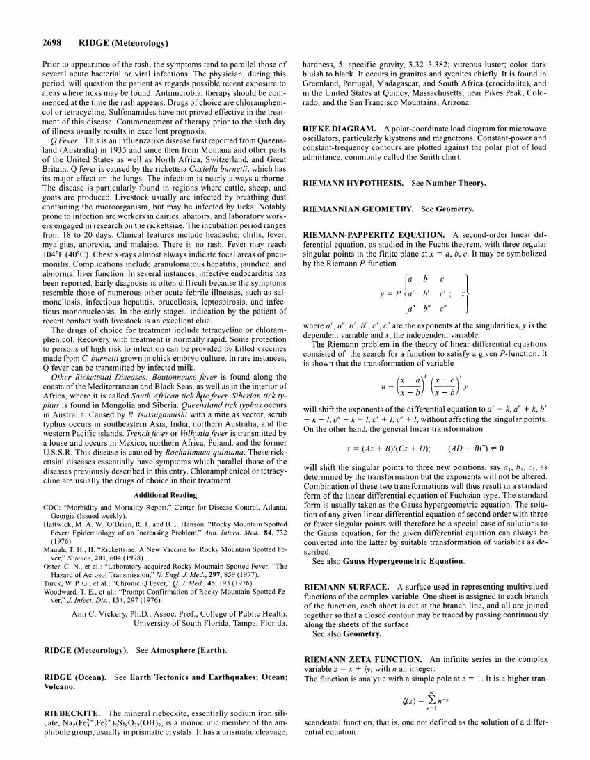
2698 RIDGE (Meteorology)
Prior to appearance of the rash, the symptoms tend to parallel those of several acute bacterial or viral infections. The physician, during this period, will question the patient as regards possible recent exposure to areas where ticks may be found. Antimicrobial therapy should be commenced at the time the rash appears. Drugs of choice are chloramphenicol or tetracycline. Sulfonamides have not proved effective in the treatment of this disease. Commencement of therapy prior to the sixth day of illness usually results in excellent prognosis.
Q Fever. This is an influenzalike disease first reported from Queensland (Australia) in 1935 and since then from Montana and other parts of the United States as well as North Africa, Switzerland, and Great Britain. Q fever is caused by the rickettsia Coxiella burnetii, which has its major effect on the lungs. The infection is nearly always airborne. The disease is particularly found in regions where cattle, sheep, and goats are produced. Livestock usually are infected by breathing dust containing the microorganism, but may be infected by ticks. Notably prone to infection are workers in dairies, abatoirs, and laboratory workers engaged in research on the rickettsiae. The incubation period ranges from 18 to 20 days. Clinical features include headache, chills, fever, myalgias, anorexia, and malaise. There is no rash. Fever may reach 104°F (40°C). Chest x-rays almost always indicate focal areas of pneumonitis. Complications include granulomatous hepatitis, jaundice, and abnormal liver function. In several instances, infective endocarditis has been reported. Early diagnosis is often difficult because the symptoms resemble those of numerous other acute febrile illnesses, such as salmonellosis, infectious hepatitis, brucellosis, leptospirosis, and infectious mononucleosis. In the early stages, indication by the patient of recent contact with livestock is an excellent clue.
The drugs of choice for treatment include tetracycline or chloramphenicol. Recovery with treatment is normally rapid. Some protection to persons of high risk to infection can be provided by killed vaccines made from C. burnetti grown in chick embryo culture. In rare instances, Q fever can be transmitted by infected milk.
Other Rickettsial Diseases. Boutonneuse fever is found along the coasts of the Mediterranean and Black Seas, as well as in the interior of Africa, where it is called South African tick btte fever. Siberian tick typhus is found in Mongolia and Siberia. QueeAsland tick typhus occurs in Australia. Caused by R. tsutsugamushi with a mite as vector, scrub typhus occurs in southeastern Asia, India, northern Australia, and the western Pacific islands. Trench fever or Volhynia fever is transmitted by a louse and occurs in Mexico, northern Africa, Poland, and the former U.S.S.R. This disease is caused by Rochalimaea quintana. These rickettsial diseases essentially have symptoms which parallel those of the diseases previously described in this entry. Chloramphenicol or tetracycline are usually the drugs of choice in their treatment.
Additional Reading
CDC: "Morbidity and Mortality Report," Center for Disease Control, Atlanta, Georgia (Issued weekly).
Hattwick, M.A. W., O'Brien, R. 1., and B. F. Hanson: "Rocky Mountain Spotted Fever: Epidemiology of an Increasing Problem," Ann. Intern. Med.. 84, 732 ( !976).
Maugh, T. H., II: "Rickettsiae: A New Vaccine for Rocky Mountain Spotted Fever," Science, 201, 604 ( !978).
Oster, C. N., et al.: "Laboratory-acquired Rocky Mountain Spotted Fever: "The Hazard of Aerosol Transmission," N. Engl. J Me d., 297, 859 ( !977).
Turck, W. P. G., et al.: "Chronic Q Fever," Q. J Med., 45, !93 (1976). Woodward, T. E., et al.: "Prompt Confirmation of Rocky Mountain Spotted Fe
ver," J Infect. Dis., 134, 297 (!976).
Ann C. Vickery, Ph.D., Assoc. Prof., College of Public Health, University of South Florida, Tampa, Florida.
RIDGE (Meteorology). See Atmosphere (Earth).
RIDGE (Ocean). See Earth Tectonics and Earthquakes; Ocean; Volcano.
RIEBECKITE. The mineral riebeckite, essentially sodium iron silicate, NaiFe~+ ,Fe~+)sSi 8022(0Hh, is a monoclinic member of the amphibole group, usually in prismatic crystals. It has a prismatic cleavage;
hardness, 5; specific gravity, 3.32-3.382; vitreous luster; color dark bluish to black. It occurs in granites and syenites chiefly. It is found in Greenland, Portugal, Madagascar, and South Africa (crocidolite), and in the United States at Quincy, Massachusetts; near Pikes Peak, Colorado, and the San Francisco Mountains, Arizona.
RIEKE DIAGRAM. A polar-coordinate load diagram for microwave oscillators, particularly klystrons and magnetrons. Constant-power and constant-frequency contours are plotted against the polar plot of load admittance, commonly called the Smith chart.
RIEMANN HYPOTHESIS. See Number Theory.
RIEMANNIAN GEOMETRY. See Geometry.
RIEMANN-PAPPERITZ EQUATION. A second-order linear differential equation, as studied in the Fuchs theorem, with three regular singular points in the finite plane at x = a, b, c. It may be symbolized by the Riemann ?-function
y ~ p 1:, b c
b' c' . '
a" b" c"
where a', a", b', b", c', c" are the exponents at the singularities, y is the dependent variable and x, the independent variable.
The Riemann problem in the theory of linear differential equations consisted of the search for a function to satisfy a given ?-function. It is shown that the transformation of variable
-(x-a)k (x-c) 1 u- -- -- y
x-b x-b
will shift the exponents of the differential equation to a' + k, a" + k, b' - k- l, b" - k - l, c' + l, c" + l, without affecting the singular points. On the other hand, the general linear transformation
x = (Az + B)/(Cz +D); (AD- BC) =P 0
will shift the singular points to three new positions, say a 1, b1, c 1, as determined by the transformation but the exponents will not be altered. Combination of these two transformations will thus result in a standard form of the linear differential equation of Fuchsian type. The standard form is usually taken as the Gauss hypergeometric equation. The solution of any given linear differential equation of second order with three or fewer singular points will therefore be a special case of solutions to the Gauss equation, for the given differential equation can always be converted into the latter by suitable transformation of variables as described.
See also Gauss Hypergeometric Equation.
RIEMANN SURFACE. A surface used in representing multivalued functions of the complex variable. One sheet is assigned to each branch of the function, each sheet is cut at the branch line, and all are joined together so that a closed contour may be traced by passing continuously along the sheets of the surface.
See also Geometry.
RIEMANN ZETA FUNCTION. An infinite series in the complex variable z = x + iy, with n an integer: The function is analytic with a simple pole at z = I. It is a higher tran-
oc
~(z) = :2; n-z n=!
scendental function, that is, one not defined as the solution of a differential equation.
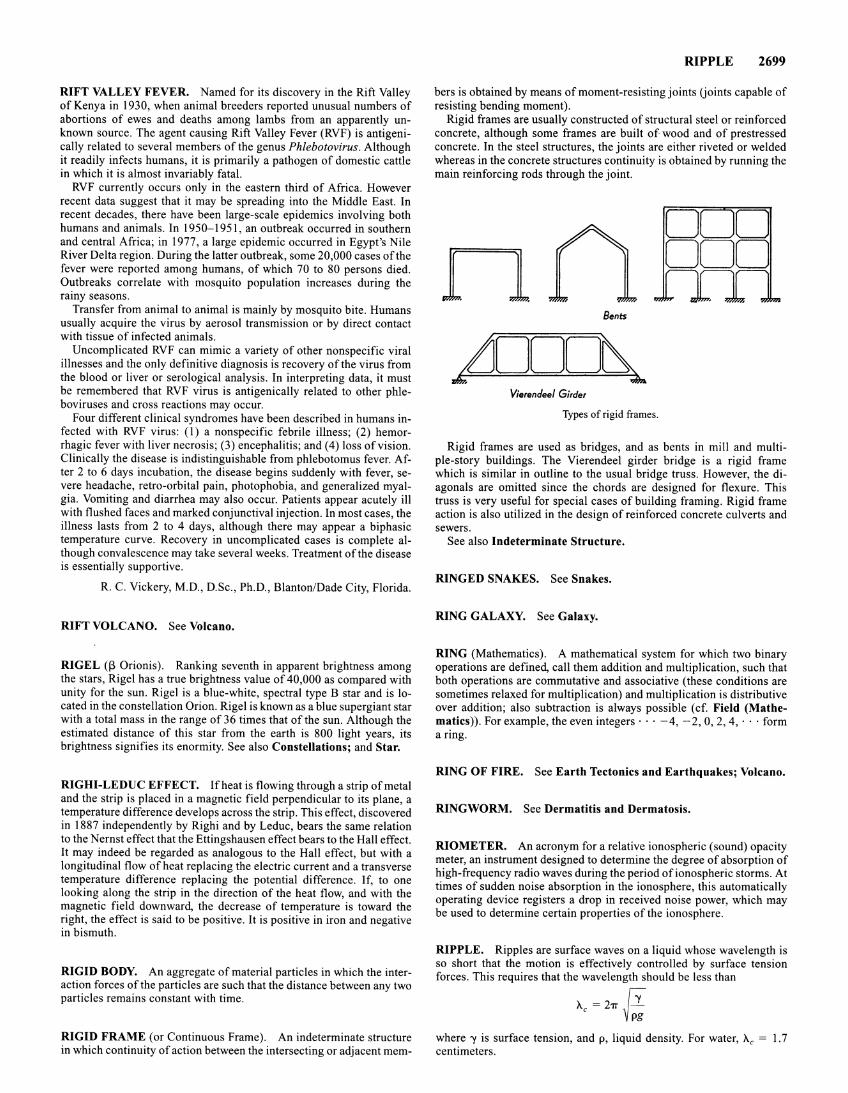
RIFT VALLEY FEVER. Named for its discovery in the Rift Valley of Kenya in 1930, when animal breeders reported unusual numbers of abortions of ewes and deaths among lambs from an apparently unknown source. The agent causing Rift Valley Fever (RVF) is antigenically related to several members of the genus Phlebotovirus. Although it readily infects humans, it is primarily a pathogen of domestic cattle in which it is almost invariably fatal.
RVF currently occurs only in the eastern third of Africa. However recent data suggest that it may be spreading into the Middle East. In recent decades, there have been large-scale epidemics involving both humans and animals. In 1950-1951, an outbreak occurred in southern and central Africa; in 1977, a large epidemic occurred in Egypt's Nile River Delta region. During the latter outbreak, some 20,000 cases of the fever were reported among humans, of which 70 to 80 persons died. Outbreaks correlate with mosquito population increases during the rainy seasons.
Transfer from animal to animal is mainly by mosquito bite. Humans usually acquire the virus by aerosol transmission or by direct contact with tissue of infected animals.
Uncomplicated RVF can mimic a variety of other nonspecific viral illnesses and the only definitive diagnosis is recovery of the virus from the blood or liver or serological analysis. In interpreting data, it must be remembered that RVF virus is antigenically related to other phleboviruses and cross reactions may occur.
Four different clinical syndromes have been described in humans infected with RVF virus: (1) a nonspecific febrile illness; (2) hemorrhagic fever with liver necrosis; (3) encephalitis; and (4) loss of vision. Clinically the disease is indistinguishable from phlebotomus fever. After 2 to 6 days incubation, the disease begins suddenly with fever, severe headache, retro-orbital pain, photophobia, and generalized myalgia. Vomiting and diarrhea may also occur. Patients appear acutely ill with flushed faces and marked conjunctival injection. In most cases, the illness lasts from 2 to 4 days, although there may appear a biphasic temperature curve. Recovery in uncomplicated cases is complete although convalescence may take several weeks. Treatment of the disease is essentially supportive.
R. C. Vickery, M.D., D.Sc., Ph.D., Blanton/Dade City, Florida.
RIFT VOLCANO. See Volcano.
RIGEL (13 Orionis). Ranking seventh in apparent brightness among the stars, Rigel has a true brightness value of 40,000 as compared with unity for the sun. Rigel is a blue-white, spectral type B star and is located in the constellation Orion. Rigel is known as a blue supergiant star with a total mass in the range of 36 times that of the sun. Although the estimated distance of this star from the earth is 800 light years, its brightness signifies its enormity. See also Constellations; and Star.
RIGHI-LEDUC EFFECT. If heat is flowing through a strip of metal and the strip is placed in a magnetic field perpendicular to its plane, a temperature difference develops across the strip. This effect, discovered in 1887 independently by Righi and by Leduc, bears the same relation to theN ernst effect that the Ettingshausen effect bears to the Hall effect. It may indeed be regarded as analogous to the Hall effect, but with a longitudinal flow of heat replacing the electric current and a transverse temperature difference replacing the potential difference. If, to one looking along the strip in the direction of the heat flow, and with the magnetic field downward, the decrease of temperature is toward the right, the effect is said to be positive. It is positive in iron and negative in bismuth.
RIGID BODY. An aggregate of material particles in which the interaction forces of the particles are such that the distance between any two particles remains constant with time.
RIGID FRAME (or Continuous Frame). An indeterminate structure in which continuity of action between the intersecting or adjacent mem-
RIPPLE 2699
hers is obtained by means of moment-resisting joints Uoints capable of resisting bending moment).
Rigid frames are usually constructed of structural steel or reinforced concrete, although some frames are built of wood and of prestressed concrete. In the steel structures, the joints are either riveted or welded whereas in the concrete structures continuity is obtained by running the main reinforcing rods through the joint.
n Bents
LJOOO~ z4m.
Vierendeel Girder
Types of rigid frames.
Rigid frames are used as bridges, and as bents in mill and multiple-story buildings. The Vierendeel girder bridge is a rigid frame which is similar in outline to the usual bridge truss. However, the diagonals are omitted since the chords are designed for flexure. This truss is very useful for special cases of building framing. Rigid frame action is also utilized in the design of reinforced concrete culverts and sewers.
See also Indeterminate Structure.
RINGED SNAKES. See Snakes.
RING GALAXY. See Galaxy.
RING (Mathematics). A mathematical system for which two binary operations are defined, call them addition and multiplication, such that both operations are commutative and associative (these conditions are sometimes relaxed for multiplication) and multiplication is distributive over addition; also subtraction is always possible ( cf. Field (Mathematics)). For example, the even integers· · · -4, -2, 0, 2, 4, · · ·form a ring.
RING OF FIRE. See Earth Tectonics and Earthquakes; Volcano.
RINGWORM. See Dermatitis and Dermatosis.
RIO METER. An acronym for a relative ionospheric (sound) opacity meter, an instrument designed to determine the degree of absorption of high-frequency radio waves during the period of ionospheric storms. At times of sudden noise absorption in the ionosphere, this automatically operating device registers a drop in received noise power, which may be used to determine certain properties of the ionosphere.
RIPPLE. Ripples are surface waves on a liquid whose wavelength is so short that the motion is effectively controlled by surface tension forces. This requires that the wavelength should be less than
A.c = 271" h ~Pi
where 'Y is surface tension, and p, liquid density. For water, Ac = 1.7 centimeters.
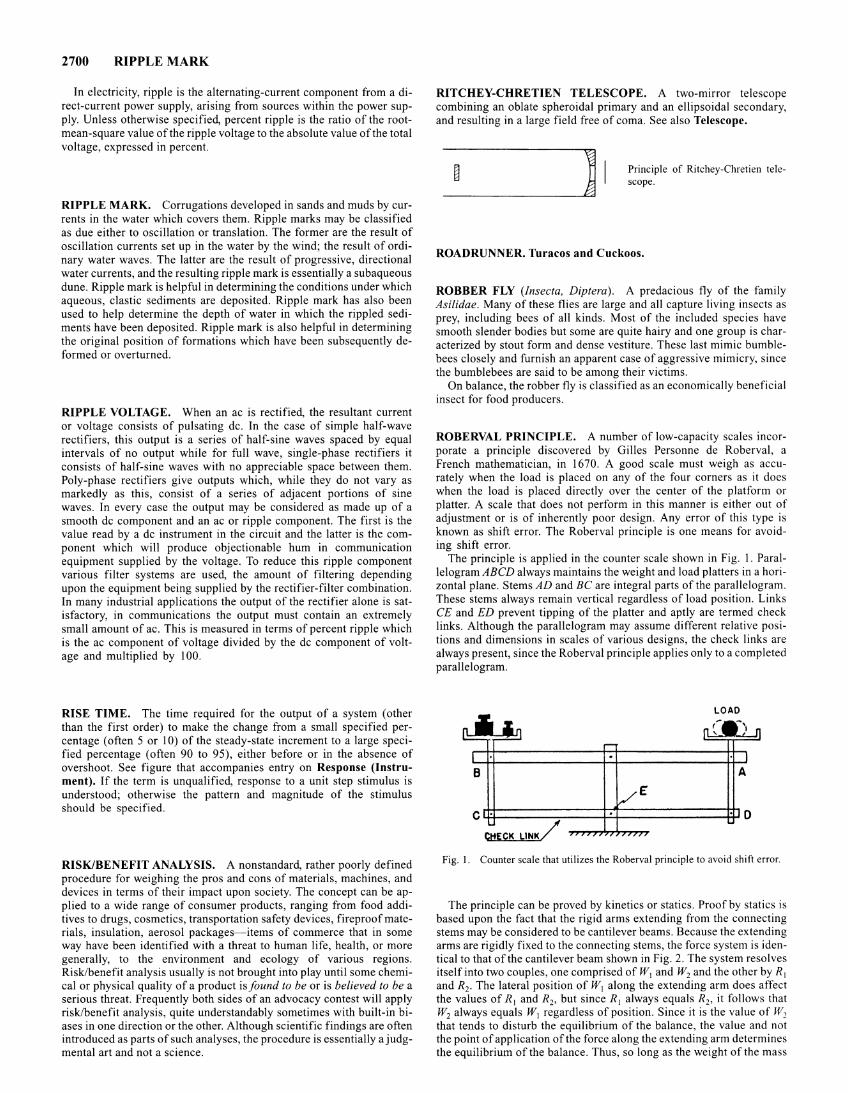
2700 RIPPLE MARK
In electricity, ripple is the alternating-current component from a direct-current power supply, arising from sources within the power supply. Unless otherwise specified, percent ripple is the ratio of the rootmean-square value of the ripple voltage to the absolute value of the total voltage, expressed in percent.
RIPPLE MARK. Corrugations developed in sands and muds by currents in the water which covers them. Ripple marks may be classified as due either to oscillation or translation. The former are the result of oscillation currents set up in the water by the wind; the result of ordinary water waves. The latter are the result of progressive, directional water currents, and the resulting ripple mark is essentially a subaqueous dune. Ripple mark is helpful in determining the conditions under which aqueous, clastic sediments are deposited. Ripple mark has also been used to help determine the depth of water in which the rippled sediments have been deposited. Ripple mark is also helpful in determining the original position of formations which have been subsequently deformed or overturned.
RIPPLE VOLTAGE. When an ac is rectified, the resultant current or voltage consists of pulsating de. In the case of simple half-wave rectifiers, this output is a series of half-sine waves spaced by equal intervals of no output while for full wave, single-phase rectifiers it consists of half-sine waves with no appreciable space between them. Poly-phase rectifiers give outputs which, while they do not vary as markedly as this, consist of a series of adjacent portions of sine waves. In every case the output may be considered as made up of a smooth de component and an ac or ripple component. The first is the value read by a de instrument in the circuit and the latter is the component which will produce objectionable hum in communication equipment supplied by the voltage. To reduce this ripple component various filter systems are used, the amount of filtering depending upon the equipment being supplied by the rectifier-filter combination. In many industrial applications the output of the rectifier alone is satisfactory, in communications the output must contain an extremely small amount of ac. This is measured in terms of percent ripple which is the ac component of voltage divided by the de component of voltage and multiplied by I 00.
RISE TIME. The time required for the output of a system (other than the first order) to make the change from a small specified percentage (often 5 or I 0) of the steady-state increment to a large specified percentage (often 90 to 95), either before or in the absence of overshoot. See figure that accompanies entry on Response (Instrument). If the term is unqualified, response to a unit step stimulus is understood; otherwise the pattern and magnitude of the stimulus should be specified.
RISK/BENEFIT ANALYSIS. A nonstandard, rather poorly defined procedure for weighing the pros and cons of materials, machines, and devices in terms of their impact upon society. The concept can be applied to a wide range of consumer products, ranging from food additives to drugs, cosmetics, transportation safety devices, fireproof materials, insulation, aerosol packages-items of commerce that in some way have been identified with a threat to human life, health, or more generally, to the environment and ecology of various regions. Risk/benefit analysis usually is not brought into play until some chemical or physical quality of a product is found to be or is believed to be a serious threat. Frequently both sides of an advocacy contest will apply risk/benefit analysis, quite understandably sometimes with built-in biases in one direction or the other. Although scientific findings are often introduced as parts of such analyses, the procedure is essentially a judgmental art and not a science.
RITCHEY-CHRETIEN TELESCOPE. A two-mirror telescope combining an oblate spheroidal primary and an ellipsoidal secondary, and resulting in a large field free of coma. See also Telescope.
Principle of Ritchey-Chretien telescope.
ROADRUNNER. Turacos and Cuckoos.
ROBBER FLY (Insecta, Diptera). A predacious fly of the family Asilidae. Many of these flies are large and all capture living insects as prey, including bees of all kinds. Most of the included species have smooth slender bodies but some are quite hairy and one group is characterized by stout form and dense vestiture. These last mimic bumblebees closely and furnish an apparent case of aggressive mimicry, since the bumblebees are said to be among their victims.
On balance, the robber fly is classified as an economically beneficial insect for food producers.
ROBERVAL PRINCIPLE. A number of low-capacity scales incorporate a principle discovered by Gilles Personne de Roberval, a French mathematician, in 1670. A good scale must weigh as accurately when the load is placed on any of the four corners as it does when the load is placed directly over the center of the platform or platter. A scale that does not perform in this manner is either out of adjustment or is of inherently poor design. Any error of this type is known as shift error. The Roberval principle is one means for avoiding shift error.
The principle is applied in the counter scale shown in Fig. I. Parallelogram ABCD always maintains the weight and load platters in a horizontal plane. Stems AD and BC are integral parts of the parallelogram. These stems always remain vertical regardless of load position. Links CE and ED prevent tipping of the platter and aptly are termed check links. Although the parallelogram may assume different relative positions and dimensions in scales of various designs, the check links are always present, since the Roberval principle applies only to a completed parallelogram.
LOAD
Fig. I. Counter scale that utilizes the Roberval principle to avoid shift error.
The principle can be proved by kinetics or statics. Proof by statics is based upon the fact that the rigid arms extending from the connecting stems may be considered to be cantilever beams. Because the extending arms are rigidly fixed to the connecting stems, the force system is identical to that of the cantilever beam shown in Fig. 2. The system resolves itself into two couples, one comprised of W1 and W2 and the other by R1
and R2• The lateral position of W1 along the extending arm does affect the values of R 1 and R2, but since R 1 always equals R2, it follows that w2 always equals WI regardless of position. Since it is the value of w2 that tends to disturb the equilibrium of the balance, the value and not the point of application of the force along the extending arm determines the equilibrium of the balance. Thus, so long as the weight of the mass
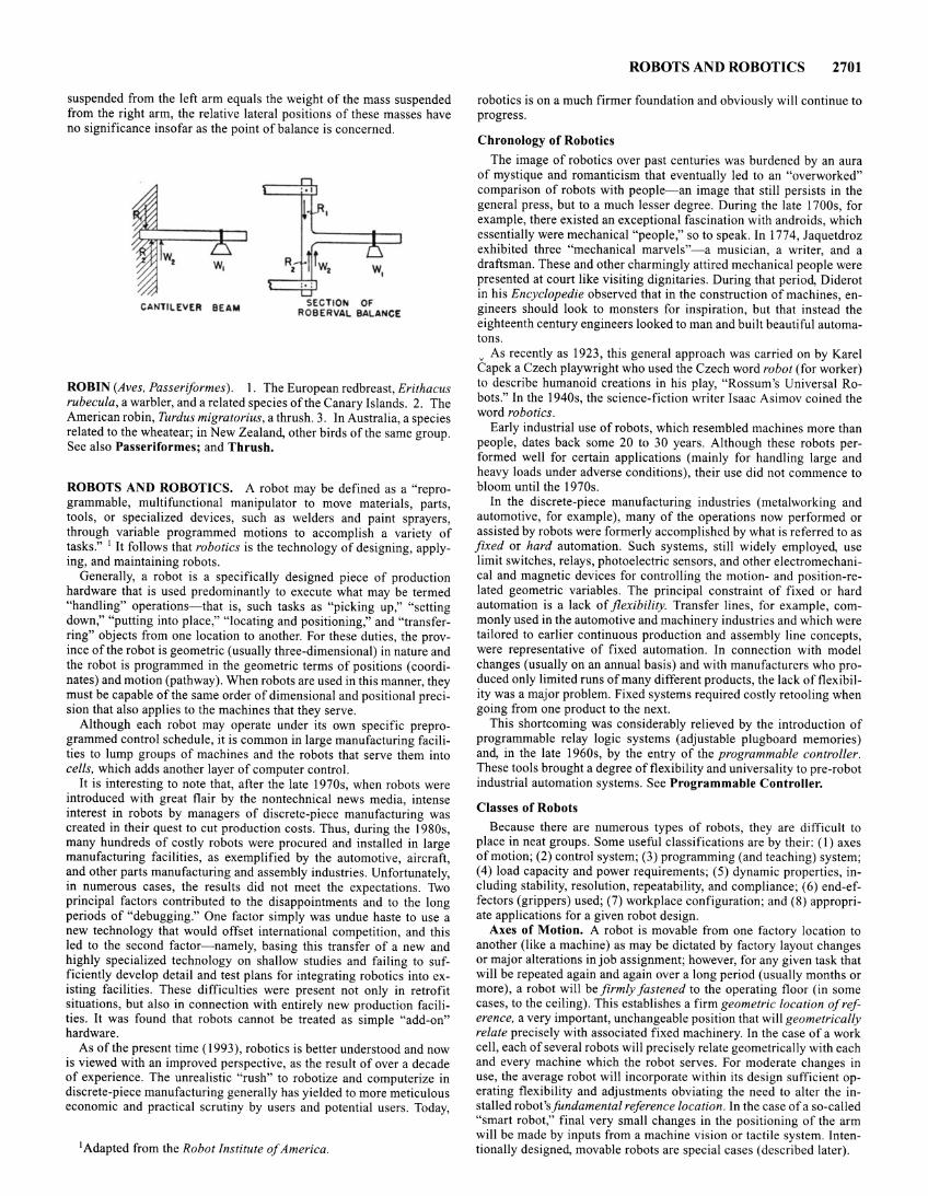
suspended from the left arm equals the weight of the mass suspended from the right arm, the relative lateral positions of these masses have no significance insofar as the point of balance is concerned.
CANTILEVER BEAM SECTION OF ROBERVAL BALANCE
ROBIN (Aves, Passeriformes ). I. The European redbreast, Erithacus rubecula, a warbler, and a related species of the Canary Islands. 2. The American robin, Turd us migratorius, a thrush. 3. In Australia, a species related to the wheatear; in New Zealand, other birds of the same group. See also Passeriformes; and Thrush.
ROBOTS AND ROBOTICS. A robot may be defined as a "reprogrammable, multifunctional manipulator to move materials, parts, tools, or specialized devices, such as welders and paint sprayers, through variable programmed motions to accomplish a variety of tasks." I It follows that robotics is the technology of designing, applying, and maintaining robots.
Generally, a robot is a specifically designed piece of production hardware that is used predominantly to execute what may be termed "handling" operations- that is, such tasks as "picking up," "setting down," "putting into place," "locating and positioning," and "transferring" objects from one location to another. For these duties, the province of the robot is geometric (usually three-dimensional) in nature and the robot is programmed in the geometric terms of positions ( coordinates) and motion (pathway). When robots are used in this manner, they must be capable of the same order of dimensional and positional precision that also applies to the machines that they serve.
Although each robot may operate under its own specific preprogrammed control schedule, it is common in large manufacturing facilities to lump groups of machines and the robots that serve them into cells, which adds another layer of computer control.
It is interesting to note that, after the late 1970s, when robots were introduced with great flair by the nontechnical news media, intense interest in robots by managers of discrete-piece manufacturing was created in their quest to cut production costs. Thus, during the 1980s, many hundreds of costly robots were procured and installed in large manufacturing facilities, as exemplified by the automotive, aircraft, and other parts manufacturing and assembly industries. Unfortunately, in numerous cases, the results did not meet the expectations. Two principal factors contributed to the disappointments and to the long periods of "debugging." One factor simply was undue haste to use a new technology that would offset international competition, and this led to the second factor- namely, basing this transfer of a new and highly specialized technology on shallow studies and failing to sufficiently develop detail and test plans for integrating robotics into existing facilities. These difficulties were present not only in retrofit situations, but also in connection with entirely new production facilities. It was found that robots cannot be treated as simple "add-on" hardware.
As of the present time ( 1993 ), robotics is better understood and now is viewed with an improved perspective, as the result of over a decade of experience. The unrealistic "rush" to robotize and computerize in discrete-piece manufacturing generally has yielded to more meticulous economic and practical scrutiny by users and potential users. Today,
I Adapted from the Robot Institute of America.
ROBOTS AND ROBOTICS 2701
robotics is on a much firmer foundation and obviously will continue to progress.
Chronology of Robotics
The image of robotics over past centuries was burdened by an aura of mystique and romanticism that eventually led to an "overworked" comparison of robots with people-an image that still persists in the general press, but to a much lesser degree. During the late 1700s, for example, there existed an exceptional fascination with androids, which essentially were mechanical "people," so to speak. In 1774, Jaquetdroz exhibited three "mechanical marvels"-a musician, a writer, and a draftsman. These and other charmingly attired mechanical people were presented at court like visiting dignitaries. During that period, Diderot in his Encyclopedie observed that in the construction of machines, engineers should look to monsters for inspiration, but that instead the eighteenth century engineers looked to man and built beautiful automatons. v As recently as 1923, this general approach was carried on by Karel Capek a Czech playwright who used the Czech word robot (for worker) to describe humanoid creations in his play, "Rossum's Universal Robots." In the 1940s, the science-fiction writer Isaac Asimov coined the word robotics.
Early industrial use of robots, which resembled machines more than people, dates back some 20 to 30 years. Although these robots performed well for certain applications (mainly for handling large and heavy loads under adverse conditions), their use did not commence to bloom until the 1970s.
In the discrete-piece manufacturing industries (metalworking and automotive, for example), many of the operations now performed or assisted by robots were formerly accomplished by what is referred to as fixed or hard automation. Such systems, still widely employed, use limit switches, relays, photoelectric sensors, and other electromechanical and magnetic devices for controlling the motion- and position-related geometric variables. The principal constraint of fixed or hard automation is a lack of flexibility. Transfer lines, for example, commonly used in the automotive and machinery industries and which were tailored to earlier continuous production and assembly line concepts, were representative of fixed automation. In connection with model changes (usually on an annual basis) and with manufacturers who produced only limited runs of many different products, the lack of flexibility was a major problem. Fixed systems required costly retooling when going from one product to the next.
This shortcoming was considerably relieved by the introduction of programmable relay logic systems (adjustable plugboard memories) and, in the late 1960s, by the entry of the programmable controller. These tools brought a degree of flexibility and universality to pre-robot industrial automation systems. See Programmable Controller.
Classes of Robots
Because there are numerous types of robots, they are difficult to place in neat groups. Some useful classifications are by their: (I) axes of motion; (2) control system; (3) programming (and teaching) system; ( 4) load capacity and power requirements; (5) dynamic properties, including stability, resolution, repeatability, and compliance; (6) end-effectors (grippers) used; (7) workplace configuration; and (8) appropriate applications for a given robot design.
Axes of Motion. A robot is movable from one factory location to another (like a machine) as may be dictated by factory layout changes or major alterations in job assignment; however, for any given task that will be repeated again and again over a long period (usually months or more), a robot will be firmly fastened to the operating floor (in some cases, to the ceiling). This establishes a firm geometric location of reference, a very important, unchangeable position that will geometrically relate precisely with associated fixed machinery. In the case of a work cell, each of several robots will precisely relate geometrically with each and every machine which the robot serves. For moderate changes in use, the average robot will incorporate within its design sufficient operating flexibility and adjustments obviating the need to alter the installed robot's fundamental reference location. In the case of a so-called "smart robot," final very small changes in the positioning of the arm will be made by inputs from a machine vision or tactile system. Intentionally designed, movable robots are special cases (described later).
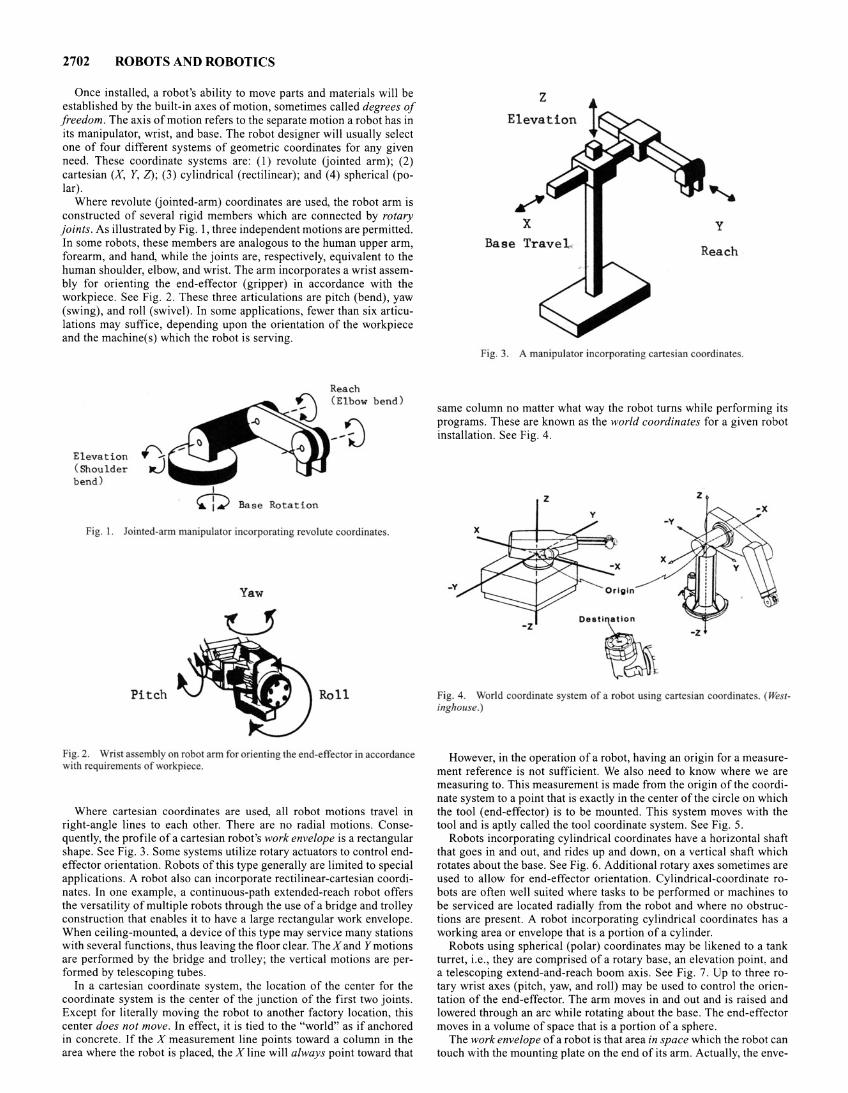
2702 ROBOTS AND ROBOTICS
Once installed, a robot's ability to move parts and materials will be established by the built-in axes of motion, sometimes called degrees of freedom. The axis of motion refers to the separate motion a robot has in its manipulator, wrist, and base. The robot designer will usually select one of four different systems of geometric coordinates for any given need. These coordinate systems are: (I) revolute Uointed arm); (2) cartesian (X, Y, Z); (3) cylindrical (rectilinear); and ( 4) spherical (polar).
Where revolute Uointed-arm) coordinates are used, the robot arm is constructed of several rigid members which are connected by rotary joints. As illustrated by Fig. 1, three independent motions are permitted. In some robots, these members are analogous to the human upper arm, forearm, and hand, while the joints are, respectively, equivalent to the human shoulder, elbow, and wrist. The arm incorporates a wrist assembly for orienting the end-effector (gripper) in accordance with the workpiece. See Fig. 2. These three articulations are pitch (bend), yaw (swing), and roll (swivel). In some applications, fewer than six articulations may suffice, depending upon the orientation of the workpiece and the machine(s) which the robot is serving.
Elevation 0, (Shoulder JtJ bend)
Reach (El bow bend )
--0
Fig. I. Jointed-arm manipulator incorporating revolute coordinate .
Yaw
Pitch Roll
Fig. 2. Wrist assembly on robot arm for orienting the end-effector in accordance with requirements of workpiece.
Where cartesian coordinates are used, all robot motions travel in right-angle lines to each other. There are no radial motions. Consequently, the profile of a cartesian robot's work envelope is a rectangular shape. See Fig. 3. Some systems utilize rotary actuators to control endeffector orientation. Robots of this type generally are limited to special applications. A robot also can incorporate rectilinear-cartesian coordinates. In one example, a continuous-path extended-reach robot offers the versatility of multiple robots through the use of a bridge and trolley construction that enables it to have a large rectangular work envelope. When ceiling-mounted, a device of this type may service many stations with several functions, thus leaving the floor clear. The X and Y motions are performed by the bridge and trolley; the vertical motions are performed by telescoping tubes.
In a cartesian coordinate system, the location of the center for the coordinate system is the center of the junction of the first two joints. Except for literally moving the robot to another factory location, this center does not move. In effect, it is tied to the "world" as if anchored in concrete. If the X measurement line points toward a column in the area where the robot is placed, the X line will always point toward that
z Elevation
/ X y
Base Trave Reach
Fig. 3. A manipulator incorporating cartesian coordinates.
same column no matter what way the robot turns while performing its programs. These are known as the world coordinates for a given robot installation. See Fig. 4.
z z y
-z ... .,~ Fig. 4. World coordinate y tern of a robot u ing cartesian coordinates. (Westinghouse.)
However, in the operation of a robot, having an origin for a measurement reference is not sufficient. We also need to know where we are measuring to. This measurement is made from the origin of the coordinate system to a point that is exactly in the center ofthe circle on which the tool (end-effector) is to be mounted. This system moves with the tool and is aptly called the tool coordinate system. See Fig. 5.
Robots incorporating cylindrical coordinates have a horizontal shaft that goes in and out, and rides up and down, on a vertical shaft which rotates about the base. See Fig. 6. Additional rotary axes sometimes are used to allow for end-effector orientation. Cylindrical-coordinate robots are often well suited where tasks to be performed or machines to be serviced are located radially from the robot and where no obstructions are present. A robot incorporating cylindrical coordinates has a working area or envelope that is a portion of a cylinder.
Robots using spherical (polar) coordinates may be likened to a tank turret, i.e., they are comprised of a rotary base, an elevation point. and a telescoping extend-and-reach boom axis. See Fig. 7. Up to three rotary wrist axes (pitch, yaw, and roll) may be used to control the orientation of the end-effector. The arm moves in and out and is raised and lowered through an arc while rotating about the base. The end-effector moves in a volume of space that is a portion of a sphere.
The work envelope of a robot is that area in space which the robot can touch with the mounting plate on the end of its arm. Actually, the enve-
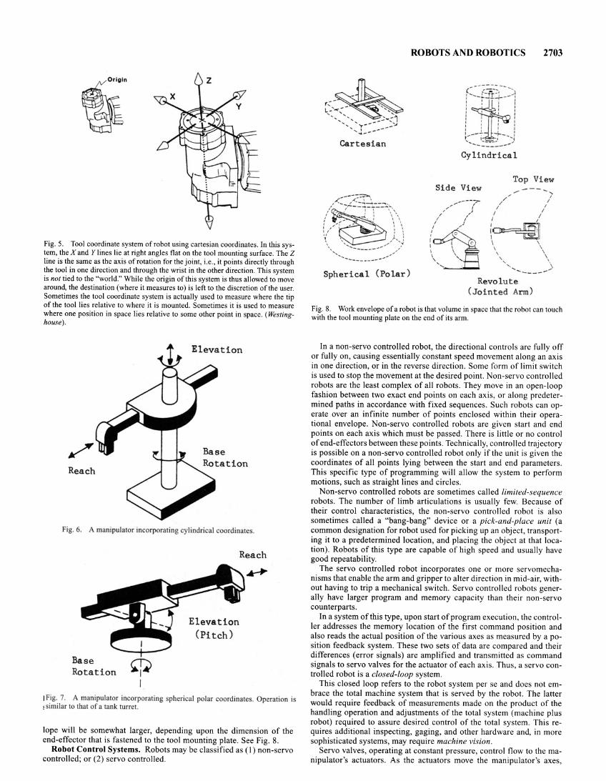
Fig. 5. Tool coordinate system of robot using cartesian coordinates. In this system, the X and Y lines lie at right angles flat on the tool mounting surface. The Z line is the same as the axis of rotation for the joint, i.e., it points directly through the tool in one direction and through the wrist in the other direction. This system is not tied to the "world." While the origin of this system is thus allowed to move around, the destination (where it measures to) is left to the discretion of the user. Sometimes the tool coordinate system is actually used to measure where the tip of the tool lies relative to where it is mounted. Sometimes it is used to measure where one position in space lies relative to some other point in space. (Westinghouse).
Elevation
Reach
Fig. 6. A manipulator incorporating cylindrical coordinates.
Base Rotation ~
I
Reach
Elevation (Pitch)
I Fig. 7. A manipulator incorporating spherical polar coordinates. Operation is ~ imilar to that of a tank turret.
lope will be somewhat larger, depending upon the dimension of the end-effector that is fastened to the tool mounting plate. See Fig. 8.
Robot Control Systems. Robots may be classified as (I) non-servo controlled; or (2) servo controlled.
ROBOTS AND ROBOTICS 2703
Cartesian
Spherical (Polar)
Cylindrical
Top Vi ew Side View ,.,----...,
/ I / I
/ I
/ I I /
~~ I ' \ \
\ \
' \ ' . ' \ .... ..... _____ .... Revolute
(Jointed Arm)
Fig. 8. Work envelope of a robot is that volume in space that the robot can touch with the tool mounting plate on the end of its arm.
In a non-servo controlled robot, the directional controls are fully off or fully on, causing essentially constant speed movement along an axis in one direction, or in the reverse direction. Some form of limit switch is used to stop the movement at the desired point. Non-servo controlled robots are the least complex of all robots. They move in an open-loop fashion between two exact end points on each axis, or along predetermined paths in accordance with fixed sequences. Such robots can operate over an infinite number of points enclosed within their operational envelope. Non-servo controlled robots are given start and end points on each axis which must be passed. There is little or no control of end-effectors between these points. Technically, controlled trajectory is possible on a non-servo controlled robot only if the unit is given the coordinates of all points lying between the start and end parameters. This specific type of programming will allow the system to perform motions, such as straight lines and circles.
Non-servo controlled robots are sometimes called limited-sequence robots. The number of limb articulations is usually few. Because of their control characteristics, the non-servo controlled robot is also sometimes called a "bang-bang" device or a pick-and-place unit (a common designation for robot used for picking up an object, transporting it to a predetermined location, and placing the object at that location). Robots of this type are capable of high speed and usually have good repeatability.
The servo controlled robot incorporates one or more servomechanisms that enable the arm and gripper to alter direction in mid-air, without having to trip a mechanical switch. Servo controlled robots generally have larger program and memory capacity than their non-servo counterparts.
In a system of this type, upon start of program execution, the controller addresses the memory location of the first command position and also reads the actual position of the various axes as measured by a position feedback system. These two sets of data are compared and their differences (error signals) are amplified and transmitted as command signals to servo valves for the actuator of each axis. Thus, a servo controlled robot is a closed-loop system.
This closed loop refers to the robot system per se and does not embrace the total machine system that is served by the robot. The latter would require feedback of measurements made on the product of the handling operation and adjustments of the total system (machine plus robot) required to assure desired control of the total system. This requires additional inspecting, gaging, and other hardware and, in more sophisticated systems, may require machine vision.
Servo valves, operating at constant pressure, control flow to the manipulator's actuators. As the actuators move the manipulator's axes,
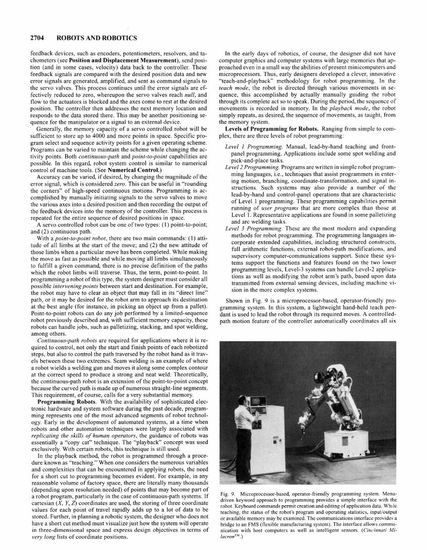
2704 ROBOTS AND ROBOTICS
feedback devices, such as encoders, potentiometers, resolvers, and tachometers (see Position and Displacement Measurement), send position (and in some cases, velocity) data back to the controller. These feedback signals are compared with the desired position data and new error signals are generated, amplified, and sent as command signals to the servo valves. This process continues until the error signals are effectively reduced to zero, whereupon the servo valves reach null, and flow to the actuators is blocked and the axes come to rest at the desired position. The controller then addresses the next memory location and responds to the data stored there. This may be another positioning sequence for the manipulator or a signal to an external device.
Generally, the memory capacity of a servo controlled robot will be sufficient to store up to 4000 and more points in space. Specific program select and sequence activity points for a given operating scheme. Programs can be varied to maintain the scheme while changing the activity points. Both continuous-path and point-to-point capabilities are possible. In this regard, robot system control is similar to numerical control of machine tools. (See Numerical Control.)
Accuracy can be varied, if desired, by changing the magnitude of the error signal, which is considered zero. This can be useful in "rounding the corners" of high-speed continuous motions. Programming is accomplished by manually initiating signals to the servo valves to move the various axes into a desired position and then recording the output of the feedback devices into the memory of the controller. This process is repeated for the entire sequence of desired positions in space.
A servo controlled robot can be one of two types: (I) point-to-point; and (2) continuous path.
With a point-to-point robot, there are two main commands: (I) attitude of all limbs at the start of the move; and (2) the new attitude of those limbs when a particular move has been completed. While making the move as fast as possible and while moving all limbs simultaneously to fulfill a given command, there is no precise definition of the paths which the robot limbs will traverse. Thus, the term, point-to-point. In programming a robot of this type, the system designer must consider all possible intervening points between start and destination. For example, the robot may have to clear an object that may fall in its "direct line" path, or it may be desired for the robot arm to approach its destination at the best angle (for instance, in picking an object up from a pallet). Point-to-point robots can do any job performed by a limited-sequence robot previously described and, with sufficient memory capacity, these robots can handle jobs, such as palletizing, stacking, and spot welding, among others.
Continuous-path robots are required for applications where it is required to control, not only the start and finish points of each robotized steps, but also to control the path traversed by the robot hand as it travels between these two extremes. Seam welding is an example of where a robot wields a welding gun and moves it along some complex contour at the correct speed to produce a strong and neat weld. Theoretically, the continuous-path robot is an extension of the point-to-point concept because the curved path is made up of numerous straight-line segments. This requirement, of course, calls for a very substantial memory.
Programming Robots. With the availability of sophisticated electronic hardware and system software during the past decade, programming represents one of the most advanced segments of robot technology. Early in the development of automated systems, at a time when robots and other automation techniques were largely associated with replicating the skills of human operators, the guidance of robots was essentially a "copy cat" technique. The "playback" concept was used exclusively. With certain robots, this technique is still used.
In the playback method, the robot is programmed through a procedure known as "teaching." When one considers the numerous variables and complexities that can be encountered in applying robots, the need for a short cut to programming becomes evident. For example, in any reasonable volume of factory space, there are literally many thousands (depending upon resolution needed) of points that may become part of a robot program, particularly in the case of continuous-path systems. If cartesian (X, Y, Z) coordinates are used, the storing of three coordinate values for each point of travel rapidly adds up to a lot of data to be stored. Further, in planning a robotic system, the designer who does not have a short cut method must visualize just how the system will operate in three-dimensional space and express design objectives in terms of very long lists of coordinate positions.
In the early days of robotics, of course, the designer did not have computer graphics and computer systems with large memories that approached even in a small way the abilities of present minicomputers and microprocessors. Thus, early designers developed a clever, innovative "teach-and-playback" methodology for robot programming. In the teach mode, the robot is directed through various movements in sequence, this accomplished by actually manually guiding the robot through its complete act so to speak. During the period, the sequence of movements is recorded in memory. In the playback mode, the robot simply repeats, as desired, the sequence of movements, as taught, from the memory system.
Levels of Programming for Robots. Ranging from simple to complex, there are three levels of robot programming:
Level 1 Programming. Manual, lead-by-hand teaching and frontpanel programming. Applications include some spot welding and pick-and-place tasks.
Level 2 Programming. Programs are written in simple robot programming languages, i.e., techniques that assist programmers in entering motion, branching, coordinate-transformation, and signal instructions. Such systems may also provide a number of the lead-by-hand and control-panel operations that are characteristic of Level I programming. These programming capabilities permit running of user programs that are more complex than those at Level I. Representative applications are found in some palletizing and arc welding tasks.
Level 3 Programming. These are the most modern and expanding methods for robot programming. The programming languages incorporate extended capabilities, including structured constructs, full arithmetic functions, external robot-path modifications, and supervisory computer-communications support. Since these systems support the functions and features found on the two lower programming levels, Level-3 systems can handle Level-2 applications as well as modifying the robot arm's path, based upon data transmitted from external sensing devices, including machine vision in the more complex systems.
Shown in Fig. 9 is a microprocessor-based, operator-friendly programming system. In this system, a lightweight hand-held teach pendant is used to lead the robot through its required moves. A controlledpath motion feature of the controller automatically coordinates all six
Fig. 9. Microprocessor-based, operator-friendly programming system. Menudriven keyword approach to programming provides a simple interface with the robot. Keyboard commands permit creation and editing of application data. Wh1le teaching, the status of the robot's program and operating statistics, input/output or available memory may be examined. The communications interface provides a bridge to an FMS (flexible manufacturing system). The interface allows communication with host computers as well as intelligent sensors. (Cincinnati Mi/acron™.)
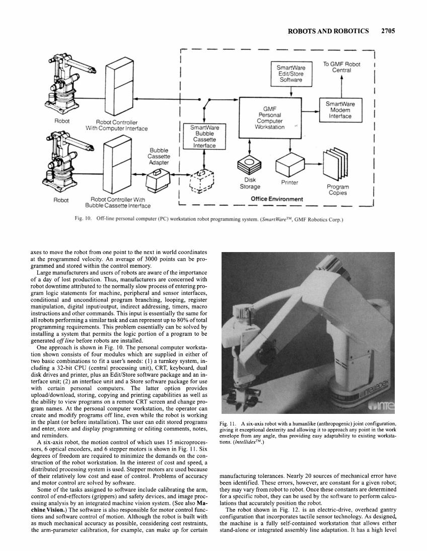
Bubble Cassette
r I
I I
Adapter j
r SmartWare
Bubble Cassette Interface
-, ...... .. ~~ ...... ~ I · : ! L_ , ..,-;/ I t.~ ...
ROBOTS AND ROBOTICS
----1 .--S-m_a_rt_W- ar-e---. To G MF Robot
Central EdiUStore Software
GMF Personal
Computer Workstation
Disk Storage
SmartWare Modem
Interface
Program Coptes
I
I I I I I I I I
2705
Robot Robot Con roller With Bubble Casse e Interface L - -- --
Office Environment _ I
Fig. 10. OfT-line personal computer (P ) work tation robot programming y tern. ( martWareTM, GMF Robotic orp.)
axes to move the robot from one point to the next in world coordinates at the programmed velocity. An average of 3000 points can be programmed and stored within the control memory.
Large manufacturers and users of robots are aware of the importance of a day of lost production. Thus, manufacturers are concerned with robot downtime attributed to the normally slow process of entering program logic statements for machine, peripheral and sensor interfaces, conditional and unconditional program branching, looping, register manipulation, digital input/output, indirect addressing, timers, macro instructions and other commands. This input is essentially the same for all robots performing a similar task and can represent up to 80% of total programming requirements. This problem essentially can be solved by installing a system that permits the logic portion of a program to be generated off line before robots are installed.
One approach is shown in Fig. I 0. The personal computer workstation shown consists of four modules which are supplied in either of two basic combinations to fit a user's needs: (1) a turnkey system, including a 32-bit CPU (central processing unit), CRT, keyboard, dual disk drives and printer, plus an Edit/Store software package and an interface unit; (2) an interface unit and a Store software package for use with certain personal computers. The latter option provides upload/download, storing, copying and printing capabilities as well as the ability to view programs on a remote CRT screen and change program names. At the personal computer workstation, the operator can create and modify programs off line, even while the robot is working in the plant (or before installation). The user can edit stored programs and enter, store and display programming or editing comments, notes, and reminders.
A six-axis robot, the motion control of which uses 15 microprocessors, 6 optical encoders, and 6 stepper motors is shown in Fig. 11. Six degrees of freedom are required to minimize the demands on the construction of the robot workstation. In the interest of cost and speed, a distributed processing system is used. Stepper motors are used because of their relatively low cost and ease of control. Problems of accuracy and motor control are solved by software.
Some of the tasks assigned to software include calibrating the arm, control of end-effectors (grippers) and safety devices, and image processing analysis by an integrated machine vision system. (See also Machine1Vision.) The software is also responsible for motor control functions and software control of motion. Although the robot is built with as much mechanical accuracy as possible, considering cost restraints, the arm-parameter calibration, for example, can make up for certain
Fig. II. A six-axis robot with a humanlike (anthropogenic) joint configuration, giving it exceptional dexterity and allowing it to approach any point in the work envelope from any angle, thus providing easy adaptability to existing workstations. (Jntellidex™.)
manufacturing tolerances. Nearly 20 sources of mechanical error have been identified. These errors, however, are constant for a given robot; they may vary from robot to robot. Once these constants are determined for a specific robot, they can be used by the software to perform calculations that accurately position the robot.
The robot shown in Fig. 12. is an electric-drive, overhead gantry configuration that incorporates tactile sensor technology. As designed, the machine is a fully self-contained workstation that allows either stand-alone or integrated assembly line adaptation. It has a high level
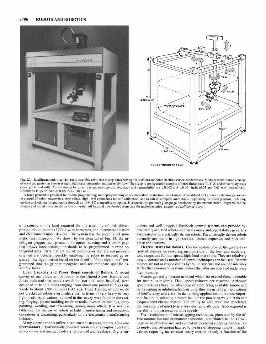
2706 ROBOTS AND ROBOTICS
94" 12388 m m ) '
( ,--
'FU LL EXTENSION OF l AXIS
)
Fig. 12. Intelligent, high-precision parts-assembly robot that incorporates both optical (vision) and force (tactile) sensors for feedback. Modular work-station concept of overhead gantry, as shown at right, facilitates integration into assembly flow. The six-axis configuration consists of three linear axes (X, Y, Z) and three rotary axes (yaw, pitch, and roll). All are driven by direct current servomotors. Accuracy and repeatability are ::'::0.002 and ::+::0.001 inch, (0.05 and 0.03 mm) respectively. Resolution is specified as 0.0005 inch (0.013 mm).
A teach pendant is provided for on-line programming and reprogramming to accommodate production line changes. A hand-held tool allows production personnel to control all robot movements, time delays, high-level commands for self-calibration, and to call up complex subroutines. Supporting the teach pendant, including on-line and off-line programming through an IBM PC compatible computer, is a special programming language developed by the manufacturer. Programs can be written and tested interactively on line or written offline and downloaded from disk for implementation. (Adaptive Intelligence Corp.)
of dexterity of the kind required for the assembly of disk drives, printed circuit boards (PCBs), wire harnesses, and telecommunication and electromechanical devices. The system has the potential of automatic laser inspection. As shown by the close-up of Fig. 13, the intelligent gripper incorporates both optical sensing and a strain gage that allows force-sensing thresholds to be programmed in three orthogonal axes. Parts that are out of tolerance or that are not properly oriented are detected quickly, enabling the robot to respond as required. Intelligent action based on the specific "force signatures" programmed into the gripper recognize and accommodate specific assembly tasks.
Load Capacity and Power Requirements of Robots. A recent survey of manufacturers of robots in the United States, Europe, and Japan indicated that models available (not total units installed) were designed to handle loads ranging from about one pound (0 .5 kg) upwards to about 2300 pounds (I 043 kg). These figures, of course, do not bracket all robots ever made, either in terms of very heavy or very light loads. Applications included in the survey were found in die casting, forging, plastic molding machine tools, investment castings, spray painting, welding, and machining, among many others. It is well established that the use of robots in light manufacturing and inspection operations is expanding, particularly in the electronics manufacturing industry.
Many electric robots utilize direct current stepping motors. (See also Servomotors.) Hydraulically powered robots usually employ hydraulic servo valves and analog resolvers for control and feedback . Digital en-
coders and well-designed feedback control systems can provide hydraulically actuated robots with an accuracy and repeatability generally associated with electrically driven robots . Pneumatically driven robots normally are found in light service, limited-sequence, and pick-andplace applications.
Electric Drives for Robots. Electric motors provide the greatest variety of choices for powering manipulators in the low- and moderateload range, and for low-speed, high-load operations. They are relatively easy to control and a number of control techniques can be used. Electric motors are not as responsive as hydraulic systems and are considerably stiffer than pneumatic systems, unless the latter are operated under very high pressure.
Motors generally operate at speed which far exceed those desirable for manipulator joints. Thus, speed reducers are required. Although speed reducers have the advantage of amplifying available torque and in preventing or inhibiting back driving, they are usually a major source of inefficiency and error. In demanding applications, the most important factors in selecting a motor include the power-to-weight ratio and torque-speed characteristics . The ability to accelerate and decelerate the working load quickly is a very desirable attribute. Also required is the ability to operate at variable speeds.
The development of microstepping techniques, pioneered by the office automation and instrument industries, contributed to the knowledge of an effective use and control of electrical stepping motors. For example, microstepping had led to the use of stepping motors in applications requiring incremental rotary motion of only a fraction of the
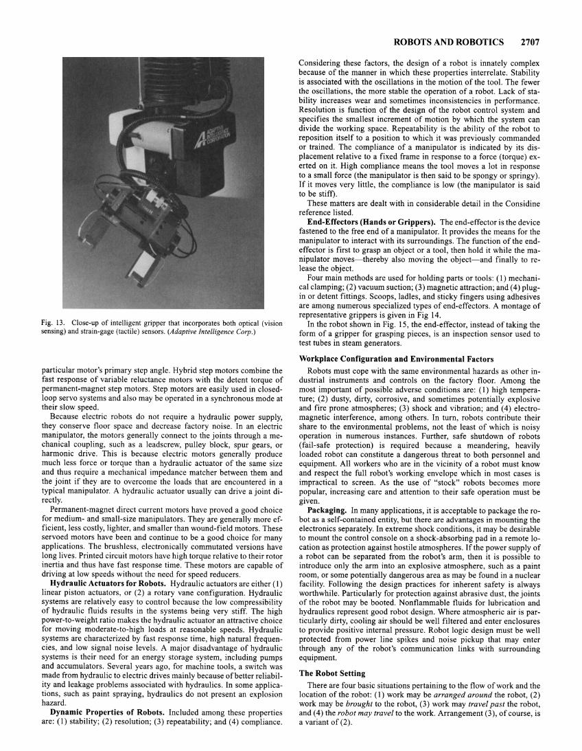
Fig. 13. Close-up of intelligent gripper that incorporates both optical (vision sensing) and strain-gage (tactile) sensors. (Adaptive Intelligence Corp.)
particular motor's primary step angle. Hybrid step motors combine the fast response of variable reluctance motors with the detent torque of permanent-magnet step motors. Step motors are easily used in closedloop servo systems and also may be operated in a synchronous mode at their slow speed.
Because electric robots do not require a hydraulic power supply, they conserve floor space and decrease factory noise. In an electric manipulator, the motors generally connect to the joints through a mechanical coupling, such as a leadscrew, pulley block, spur gears, or harmonic drive. This is because electric motors generally produce much less force or torque than a hydraulic actuator of the same size and thus require a mechanical impedance matcher between them and the joint if they are to overcome the loads that are encountered in a typical manipulator. A hydraulic actuator usually can drive a joint directly.
Permanent-magnet direct current motors have proved a good choice for medium- and small-size manipulators. They are generally more efficient, less costly, lighter, and smaller than wound-field motors. These servoed motors have been and continue to be a good choice for many applications. The brushless, electronically commutated versions have long lives. Printed circuit motors have high torque relative to their rotor inertia and thus have fast response time. These motors are capable of driving at low speeds without the need for speed reducers.
Hydraulic Actuators for Robots. Hydraulic actuators are either (I) linear piston actuators, or (2) a rotary vane configuration. Hydraulic systems are relatively easy to control because the low compressibility of hydraulic fluids results in the systems being very stiff. The high power-to-weight ratio makes the hydraulic actuator an attractive choice for moving moderate-to-high loads at reasonable speeds. Hydraulic systems are characterized by fast response time, high natural frequencies, and low signal noise levels. A major disadvantage of hydraulic systems is their need for an energy storage system, including pumps and accumulators. Several years ago, for machine tools, a switch was made from hydraulic to electric drives mainly because of better reliability and leakage problems associated with hydraulics. In some applications, such as paint spraying, hydraulics do not present an explosion hazard.
Dynamic Properties of Robots. Included among these properties are: (I) stability; (2) resolution; (3) repeatability; and ( 4) compliance.
ROBOTS AND ROBOTICS 2707
Considering these factors, the design of a robot is innately complex because of the manner in which these properties interrelate. Stability is associated with the oscillations in the motion of the tool. The fewer the oscillations, the more stable the operation of a robot. Lack of stability increases wear and sometimes inconsistencies in performance. Resolution is function of the design of the robot control system and specifies the smallest increment of motion by which the system can divide the working space. Repeatability is the ability of the robot to reposition itself to a position to which it was previously commanded or trained. The compliance of a manipulator is indicated by its displacement relative to a fixed frame in response to a force (torque) exerted on it. High compliance means the tool moves a lot in response to a small force (the manipulator is then said to be spongy or springy). If it moves very little, the compliance is low (the manipulator is said to be stiff).
These matters are dealt with in considerable detail in the Considine reference listed.
End-Effectors (Hands or Grippers). The end-effector is the device fastened to the free end of a manipulator. It provides the means for the manipulator to interact with its surroundings. The function of the endeffector is first to grasp an object or a tool, then hold it while the manipulator moves- thereby also moving the object- and finally to release the object.
Four main methods are used for holding parts or tools: (1) mechanical clamping; (2) vacuum suction; (3) magnetic attraction; and (4) plugin or detent fittings. Scoops, ladles, and sticky fingers using adhesives are among numerous specialized types of end-effectors. A montage of representative grippers is given in Fig 14.
In the robot shown in Fig. 15, the end-effector, instead of taking the form of a gripper for grasping pieces, is an inspection sensor used to test tubes in steam generators.
Workplace Configuration and Environmental Factors Robots must cope with the same environmental hazards as other in
dustrial instruments and controls on the factory floor. Among the most important of possible adverse conditions are: (I) high temperature; (2) dusty, dirty, corrosive, and sometimes potentially explosive and fire prone atmospheres; (3) shock and vibration; and (4) electromagnetic interference, among others. In turn, robots contribute their share to the environmental problems, not the least of which is noisy operation in numerous instances. Further, safe shutdown of robots (fail-safe protection) is required because a meandering, heavily loaded robot can constitute a dangerous threat to both personnel and equipment. All workers who are in the vicinity of a robot must know and respect the full robot's working envelope which in most cases is impractical to screen. As the use of "stock" robots becomes more popular, increasing care and attention to their safe operation must be given.
Packaging. In many applications, it is acceptable to package the robot as a self-contained entity, but there are advantages in mounting the electronics separately. In extreme shock conditions, it may be desirable to mount the control console on a shock-absorbing pad in a remote location as protection against hostile atmospheres. If the power supply of a robot can be separated from the robot's arm, then it is possible to introduce only the arm into an explosive atmosphere, such as a paint room, or some potentially dangerous area as may be found in a nuclear facility. Following the design practices for inherent safety is always worthwhile. Particularly for protection against abrasive dust, the joints of the robot may be booted. Nonflammable fluids for lubrication and hydraulics represent good robot design. Where atmospheric air is particularly dirty, cooling air should be well filtered and enter enclosures to provide positive internal pressure. Robot logic design must be well protected from power line spikes and noise pickup that may enter through any of the robot's communication links with surrounding equipment.
The Robot Setting There are four basic situations pertaining to the flow of work and the
location of the robot: ( 1) work may be arranged around the robot, (2) work may be brought to the robot, (3) work may travel past the robot, and ( 4) the robot may travel to the work. Arrangement (3 ), of course, is a variant of (2).
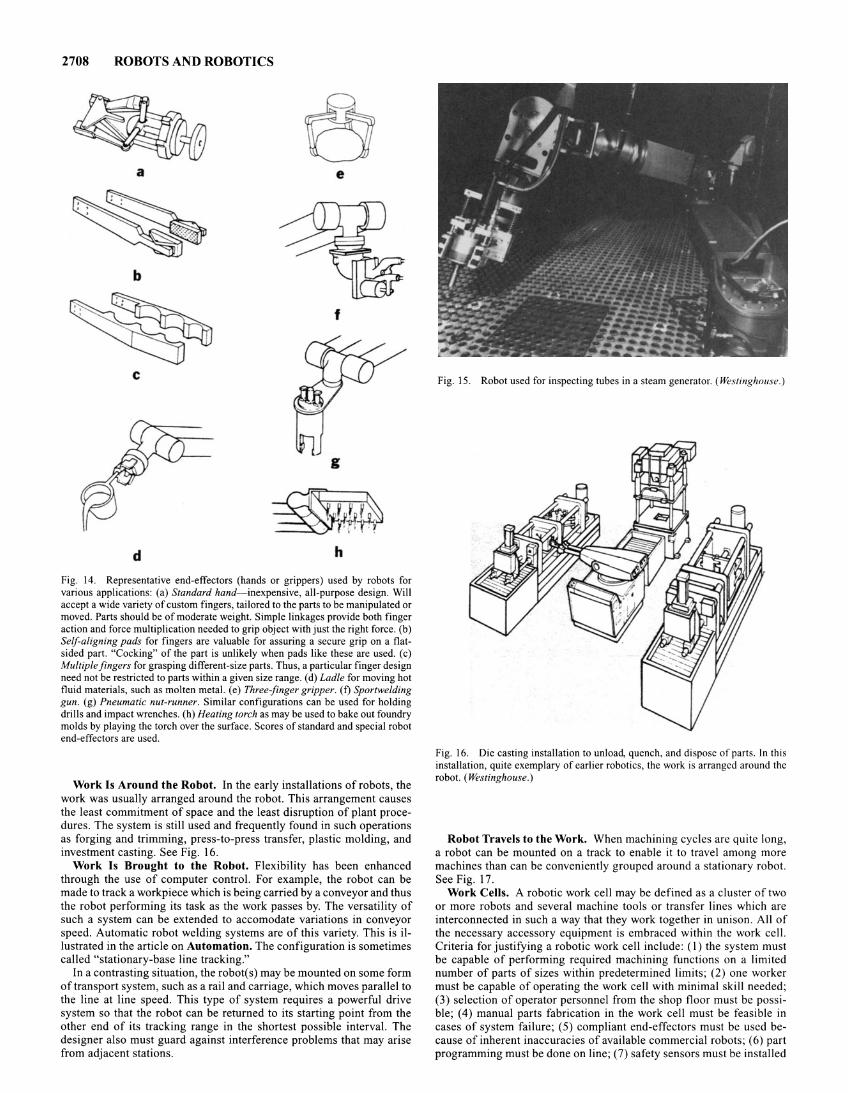
2708 ROBOTS AND ROBOTICS
a e
b
f
c
g
d h
Fig. 14. Representative end-effectors (hands or grippers) used by robots for various applications: (a) Standard hand-inexpensive, all-purpose design. Will accept a wide variety of custom fingers, tailored to the parts to be manipulated or moved. Parts should be of moderate weight. Simple linkages provide both finger action and force multiplication needed to grip object with just the right force. (b) Self-aligning pads for fingers are valuable for assuring a secure grip on a flatsided part. "Cocking" of the part is unlikely when pads like these are used. (c) Multiple fingers for grasping different-size parts. Thus, a particular finger design need not be restricted to parts within a given size range. (d) Ladle for moving hot fluid materials, such as molten metal. (e) Three-finger gripper. (f) Sportwelding gun. (g) Pneumatic nut-runner. Similar configurations can be used for holding drills and impact wrenches. (h) Heating torch as may be used to bake out foundry molds by playing the torch over the surface. Scores of standard and special robot end-effectors are used.
Work Is Around the Robot. In the early installations of robots, the work was usually arranged around the robot. This arrangement causes the least commitment of space and the least disruption of plant procedures. The system is still used and frequently found in such operations as forging and trimming, press-to-press transfer, plastic molding, and investment casting. See Fig. 16.
Work Is Brought to the Robot. Flexibility has been enhanced through the use of computer control. For example, the robot can be made to track a workpiece which is being carried by a conveyor and thus the robot performing its task as the work passes by. The versatility of such a system can be extended to accomodate variations in conveyor speed. Automatic robot welding systems are of this variety. This is illustrated in the article on Automation. The configuration is sometimes called "stationary-base line tracking."
In a contrasting situation, the robot(s) may be mounted on some form of transport system, such as a rail and carriage, which moves parallel to the line at line speed. This type of system requires a powerful drive system so that the robot can be returned to its starting point from the other end of its tracking range in the shortest possible interval. The designer also must guard against interference problems that may arise from adjacent stations.
Fig. 15. Robot used for inspecting tubes in a steam generator. (Westinghouse.)
Fig. 16. Die casting installation to unload, quench, and dispose of parts. In this installation, quite exemplary of earlier robotics, the work is arranged around the robot. (Westinghouse.)
Robot Travels to the Work. When machining cycles are quite long, a robot can be mounted on a track to enable it to travel among more machines than can be conveniently grouped around a stationary robot. See Fig. 17.
Work Celts. A robotic work celt may be defined as a cluster of two or more robots and several machine tools or transfer lines which are interconnected in such a way that they work together in unison. All of the necessary accessory equipment is embraced within the work cell. Criteria for justifying a robotic work cell include: (I) the system must be capable of performing required machining functions on a limited number of parts of sizes within predetermined limits; (2) one worker must be capable of operating the work cell with minimal skill needed; (3) selection of operator personnel from the shop floor must be possible; (4) manual parts fabrication in the work cell must be feasible in cases of system failure; (5) compliant end-effectors must be used because of inherent inaccuracies of available commercial robots; ( 6) part programming must be done on line; (7) safety sensors must be installed
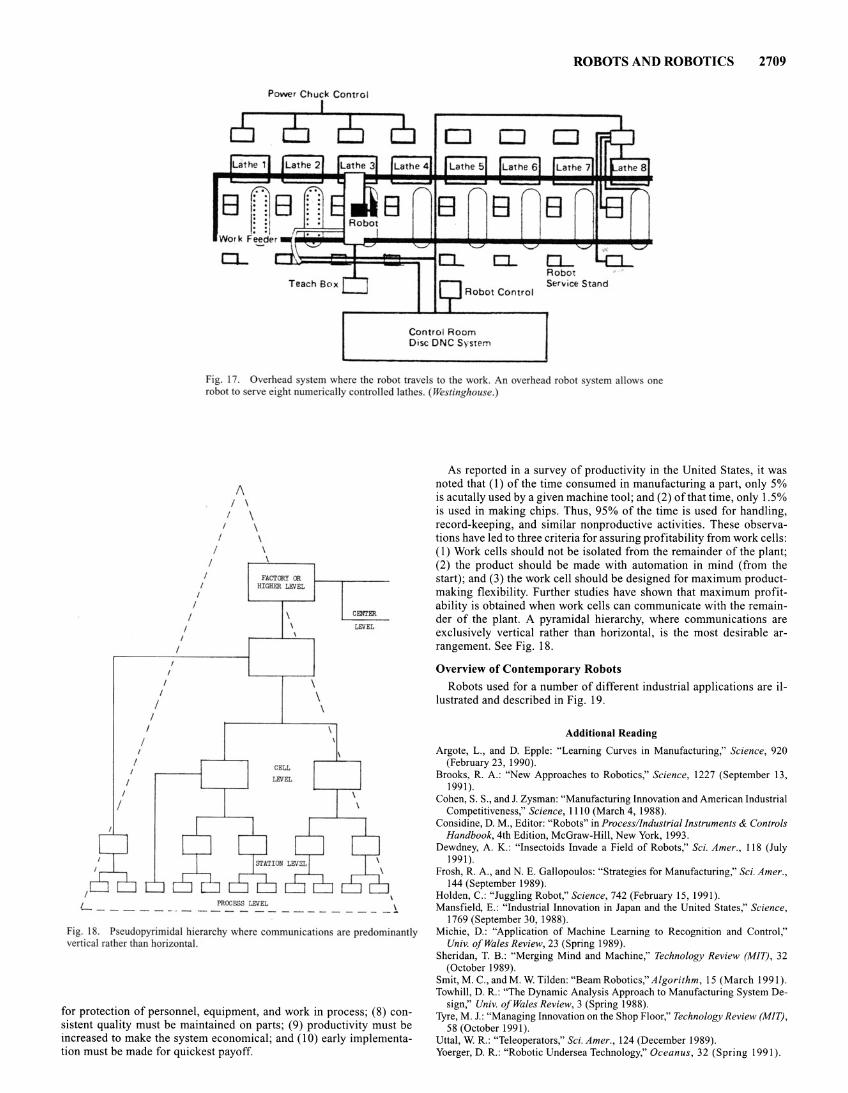
Power Chuck Control
I
[52]6
0...
ROBOTS AND ROBOTICS
Robot Sen•ice Stand
2709
Control Room Disc DNC System
Fig. 17. Overhead sy tem where the robot travels to the work. An overhead robot y tem allow one robot to serve eight numerically controlled lathes. (Westinghouse.)
I
I
I
I
I
I
I
I I
I
I
I I
I I
I
I
I I
'- ----- - · -
I
I
I I
PROCESS LEVEL
\ \ \
I
_ l
Fig. 18. Pseudopyrimidal hierarchy where communications are predominantly vertical rather than horizontal.
for protection of personnel, equipment, and work in process; (8) consistent quality must be maintained on parts; (9) productivity must be increased to make the system economical; and (I 0) early implementation must be made for quickest payoff
As reported in a survey of productivity in the United States, it was noted that ( 1) of the time consumed in manufacturing a part, only 5% is acutally used by a given machine tool; and (2) of that time, only 1.5% is used in making chips. Thus, 95% of the time is used for handling, record-keeping, and similar nonproductive activities. These observations have led to three criteria for assuring profitability from work cells: (I) Work cells should not be isolated from the remainder of the plant; (2) the product should be made with automation in mind (from the start); and (3) the work cell should be designed for maximum productmaking flexibility. Further studies have shown that maximum profitability is obtained when work cells can communicate with the remainder of the plant. A pyramidal hierarchy, where communications are exclusively vertical rather than horizontal, is the most desirable arrangement. See Fig. 18.
Overview of Contemporary Robots
Robots used for a number of different industrial applications are illustrated and described in Fig. 19.
Additional Reading
Argote, L., and D. Epple: "Learning Curves in Manufacturing," Science, 920 (February 23, 1990).
Brooks, R. A.: "New Approaches to Robotics," Science, 1227 (September 13, 1991).
Cohen, S. S., and J. Zysman: "Manufacturing Innovation and American Industrial Competitiveness," Science, 1110 (March 4, 1988).
Considine, D. M., Editor: "Robots" in Process/Industria/Instruments & Controls Handbook, 4th Edition, McGraw-Hill, New York, 1993.
Dewdney, A. K.: "lnsectoids Invade a Field of Robots," Sci. Amer., 118 (July 1991).
Frosh, R. A., and N. E. Gallopoulos: "Strategies for Manufacturing," Sci. Amer., 144 (September 1989).
Holden, C.: "Juggling Robot," Science, 742 (February 15, 1991). Mansfield, E.: "Industrial Innovation in Japan and the United States," Science,
1769 (September 30, 1988). Michie, D. : "Application of Machine Learning to Recognition and Control,"
Univ. of Wales Review, 23 (Spring 1989). Sheridan, T. B.: "Merging Mind and Machine," Technology Review (MIT), 32
(October 1989). Smit, M. C., and M. W. Tilden: "Beam Robotics," Algorithm, 15 (March 1991). Towhill, D. R.: "The Dynamic Analysis Approach to Manufacturing System De
sign," Univ. of Wales Review, 3 (Spring 1988). Tyre, M. J.: "Managing Innovation on the Shop Floor," Technology Review (MIT),
58 (October 1991). Uttal, W. R.: "Teleoperators," Sci. Amer., 124 (December 1989). Yoerger, D. R.: "Robotic Undersea Technology," Oceanus, 32 (Spring 1991).
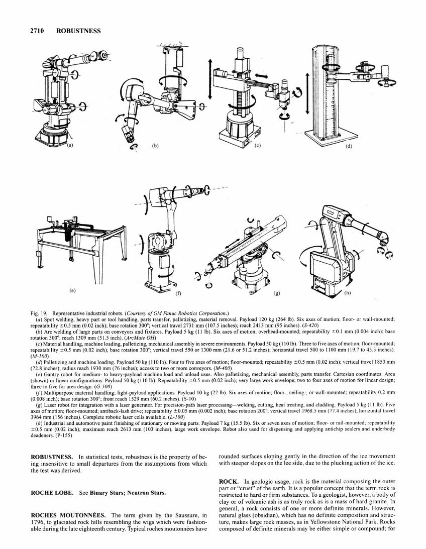
2710 ROBUSTNESS
~ (b)
(e)
Fig. 19. Representative industrial robots. (Courtesy ofGM Fanuc Robotics Corporation.) (a) Spot welding, heavy part or tool handling, parts transfer, palletizing, material removal. Payload 120 kg (264 lb). Six axes of motion; floor- or wall-mounted;
repeatability :!:0.5 mm (0.02 inch); base rotation 300°; vertical travel2731 mm (107.5 inches); reach 2413 mm (95 inches). (S-420)
(b) Arc welding of large parts on conveyors and fixtures. Payload 5 kg (II lb). Six axes of motion; overhead-mounted; repeatability :!:0.1 mm (0.004 inch); base rotation 300°; reach 1309 mm (51.5 inch). (ArcMate OH)
(c) Material handling, machine loading, palletizing, mechanical assembly in severe environments. Payload 50 kg (II 0 lb ). Three to five axes of motion; floor-mounted; repeatability :!: 0.5 mm (0.02 inch); base rotation 300°; vertical travel 550 or 1300 mm (21.6 or 51.2 inches); horizontal travel 500 to 1100 mm ( 19.7 to 43.3 inches). (M-100)
(d) Palletizing and machine loading. Payload 50 kg (110 lb). Four to five axes of motion; floor-mounted; repeatability :!:0.5 mm (0.02 inch); vertical travel 1850 mm (72.8 inches); radius reach 1930 mm (76 inches); access to two or more conveyors. (M-400)
(e) Gantry robot for medium- to heavy-payload machine load and unload uses. Also palletizing, mechanical assembly, parts transfer. Cartesian coordinates. Area (shown) or linear configurations. Payload 50 kg ( 110 lb). Repeatability :!:0.5 mm (0.02 inch); very large work envelope; two to four axes of motion for linear design; three to five for area design. ( G-500)
(j) Multipurpose material handling; light-payload applications. Payload 10 kg (22 lb). Six axes of motion; floor- , ceiling-, or wall-mounted; repeatability 0.2 mm (0.008 inch); base rotation 300°; front reach 1529 mm (60.2 inches). (S-10)
(g) Laser robot for integration with a laser generator. For precision-path laser processing- welding, cutting, heat treating, and cladding. Payload 5 kg (II lb ). Five axes of motion; floor-mounted; antiback-lash drive; repeatability :!:0.05 mm (0.002 inch); base rotation 200°; vertical travel 1968.5 mm (77.4 inches); horizontal travel 3964 mm (156 inches). Complete robotic laser cells available. (L-100)
(h) Industrial and automotive paint finishing of stationary or moving parts. Payload 7 kg ( 15.5 lb). Six or seven axes of motion; floor- or rail-mounted; repeatability :!:0.5 mm (0.02 inch); maximum reach 2613 mm (103 inches), large work envelope. Robot also used for dispensing and applying antichip sealers and underbody deadeners. (P-155)
ROBUSTNESS. In statistical tests, robustness is the property of being insensitive to small departures from the assumptions from which the test was derived.
ROCHE LOBE. See Binary Stars; Neutron Stars.
ROCHES MOUTONNEES. The term given by the Saussure, in I 796, to glaciated rock hills resembling the wigs which were fashionable during the late eighteenth century. Typical roches moutonnees have
rounded surfaces sloping gently in the direction of the ice movement with steeper slopes on the lee side, due to the plucking action of the ice.
ROCK. In geologic usage, rock is the material composing the outer part or "crust" of the earth. It is a popular concept that the term rock is restricted to hard or firm substances. To a geologist, however, a body of clay or of volcanic ash is as truly rock as is a mass of hard granite. In general, a rock consists of one or more definite minerals. However, natural glass (obsidian), which has no definite composition and structure, makes large rock masses, as in Yellowstone National Park. Rocks composed of definite minerals may be either simple or compound; for
example, the purest marble is formed entirely of the one mineral calcite, whereas granite consists of feldspar and quartz mixed in varying proportions, usually with minor quantities of mica and other accessory minerals.
All rocks are divided into three major classes, according to mode of origin. Igneous rocks are those that have been formed by cooling and solidification of molten masses derived from within the earth. Because of their origin they are sometimes called the primary rock. In part they are lavas and other products of volcanoes; other masses solidify slowly below the earth's surface to form granite and other crystalline types of igneous rock whose mineral content depends chiefly on the chemical composition of the parent molten mass. Sedimentary rocks consist of material that formed a part of pre-existent rocks, and that was moved from its former position, deposited by the action of water, the atmosphere, or glacier ice, and subsequently converted into rock. Examples are conglomerate, sandstone, and limestone. Metamorphic rocks are those that were originally igneous or sedimentary, but have been changed either in mineral composition or in texture, or in both, so that their original characters have been radically altered. Slate, formed by alteration of shale, and marble, derived from pre-existent limestone, are familiar examples.
See also Igneous Rock; and Metamorphic Rock.
ROCKET ENGINE. A reaction engine that contains within itself, or carries along with itself, all the substances necessary for its operation or for the consumption or combustion of its fuel, not requiring intake of any outside substance and hence capable of operation in outer space. Also called rocket motor. Chemical rocket engines contain or carry along their own fuel and oxidizer, usually in either liquid or solid form, and range from simple motors consisting only of a combustion chamber and exhaust nozzle to engines of some complexity incorporating, in addition, fuel and oxygen lines, pumps, cooling systems, etc., and sometimes having two or more combustion chambers. Experimental rocket motors have used neutral gas, ionized gas, and plasmas as propellants.
ROCKET PROPELLANTS. Chemical rocket propellant can be classified in several ways, including liquid or solid, monopropellant, bipropellant or tripropellant, cryogenic or storable, hypergolic or nonhypergolic, double-base, composite or composite double-base. Propellant classification frequently influences the classification of rocket engines-for example, monopropellant rocket, liquid rocket, solid rocket, and hybrid rocket (usually using a liquid oxidizer and a solid fuel). Propellants for chemical rockets serve two primary functions as contrasted to one function for nuclear, solar, electrical or laser heated rockets. In chemical propellant rockets, the propellant is both the energy source and the ejected mass or "working fluid."
Compared with the almost limitless number of chemical compounds that exist or can be formed, the number of chemical propellants in common use are relatively few. This situation arises from criteria including costs, source availability, toxicity, resistance to shock, and other requirements imposed by the vehicle application and the propulsion system design. Another practical reason is that extensive overlap of physical, chemical, and economic properties are displayed by many of the theoretically possible propellants. During the 1960s, the universities, industry, and government in the United States pursued extensive research programs for synthesizing new chemical compounds viewed as candidate propellants which would increase the performance capability of chemical rockets. Although dozens of compounds were synthesized, few results reached the production line. This does not mean, however, that a scientific breakthrough in increasing the molecular energy of a propellant may not be ultimately obtainable.
The characteristics desired of a rocket propellant are several in number and can be divided into economic, safety, materials compatibility, engine-cycle needs and vehicle requirements.
In general terms, the engine-cycle needs ideally are: (1) a propellant or propellant combination that has a high heat of reaction per unit weight (also called heat of combustion). Most vehicles add a require-
ROCKET PROPELLANTS 2711
ment for high heat of reaction per unit volume of propellant to minimize the vehicle size. (2) reaction products that are all gaseous, that have a very low molecular weight and that have a very high temperature of dissociation.
In addition to specific impulse, the vehicle requirements usually influence propellant selection in terms of storability, density, toxicity, and other hazards, and other application-sensitive factors, including exhaust plume properties and radar cross section and radiation emissions. Other factors being essentially equal, the higher the heat of reaction of a propellant (or combination), the more attractive the propellant. Sharp exceptions to this rule occur in some missiles because of volume limitations, the need for smokeless exhaust or similar restraints.
The heat released by a propellant is the difference in heat between the constituents and the end-products of combustion.
Mf:=l :L Tik(Ml(h- :L TJ/fill;),j k, products ; , reactants
where Alf,. is the heat generated; 11!1J is the standard heat of formation of the constituent at reference temperature (298K); and TJ is the number of moles of each} reactant or k product. Large heat release is afforded by reaction products having large negative values, while the reactants should have positive, or at least small negative values, if possible. The heat of reaction is often noted in energy/weight units, such as kilocalories/gram.
Specific impulse, Isp• the universally accepted measure of rocket engine performance, can also be used to indicate the performance of propellants. The most commonly stated expansion ration is I ,000 --7 14.7 giving "sea-level specific impulse at I ,000 psi chamber pressure." Sometimes the expansion ratio is I ,000 --7 0.2 to indicate specific impulse for high-altitude or space flight.
By definition, specific impulse Isp is:
F
w with the Isp units being seconds; the short designation for units of thrust (force) per units of propellant mass flow per second.
For an ideal rocket with the nozzle exhaust pressure being the ambient pressure, the thrust, recognizing Newton's second law of motion, is:
F =Wee g
where W is propellant flow rate in pounds per second; ce is exhaust velocity in feet per second; and g is the gravitational constant in feet/ second/ second.
Other formulas and derivations are given in detail in Reference I . In practice, only about 10% of the elements on the periodic chart are
adaptable to chemical rocket propellants. Propellants have made little use of elements other than hydrogen, carbon, nitrogen, oxygen, chlorine, fluorine, aluminum, boron, and beryllium.
Liquid propellants fall into two broad classes: (1) earth storable (monopropellants and bipropellants), and (2) cryogenic, depending upon whether they can be kept in the vehicle tankage for months and years, or must be used in a few hours or days. The theoretical performances of storable and cryogenic bipropellants combusting ideally at 1,000 psia chamber pressure and expanding to sea-level pressure without loss, assuming shifting chemical equilibrium of the combustion products during expansion in the engine exhaust nozzle, are listed in Tables 1 and 2. For comparison purposes, a few properties of the more common monopropellants are listed in Table 3. Water (not listed) as a source of hydrogen and oxygen via electrolysis has merit as a propellant in long-life satellites (5 years plus), equipped with solar electric cells.
Solid propellants fall into three general types: (I) double-base, (2) composite; and (3) composite double-base. Double-base propellants form a homogeneous cured propellant, usually a nitrocellulose-type of gun-powder dissolved in nitroglycerin plus minor percentages of additives. Both the major ingredients are explosives and both contribute to the functions of fuel, oxidizer, and binder. Composite propellants form

2712 ROCKET PROPELLANTS
TABLE I. STORABLE LIQUID BIPROPELLANT COMBINATIONS
Oxygen-Fuel Ratio by Weight
for Maximum Bulk Specific Theoretical Oxidizer Fuel I,P Gravity fs/
Nitrogen tetroxide 50150 Hydrazine/ 2.0 1.19 289 Unsymmetrical dimethylhydrazine
Nitrogen tetroxide Unsymmetrical dimethyl- 2.6 1.17 286 hydrazine
Nitrogen tetroxide Hydrazine 1.3 1.21 292 Red fuming nitric Unsymmetrical dimethyl- 3.4 1.28 266
acid (15% N02) hydrazine Red fuming nitric Kerosene-type fuel 5.6 1.37 257
acid (15% N02)
Maximum density red Unsymmetrical dimethyl- 2.9 1.29 278 fuming nitric acid hydrazine (mixture of red fuming nitric acid and N20 4)
N20 4 with 15% NO Unsymmetrical dimethyl- 2.6 1.15 288 hy razine
Hydrogen peroxide Hydrazine 2.0 1.24 287 Hydrogen peroxide Unsymmetrical dimethyl- 4.2 1.22 284
hydrazine Chlorine trifluoride Hydrazine 2.8 1.64 295 Chlorine trifluoride Unsymmetrical dimethyl- 3.0 1.39 280
hydrazine Chlorine pentafluoride Hydrazine 2.7 1.47 313 Chlorine pentafluoride Unsymmetrical dimethyl- 2.9 1.34 297
hydrazine Hydrazine Pentaborane 1.3 0.80 328
" I ,000 ~ 14.7 psi a, shifting equilibrium (chemical composition of exhaust gases changes during nozzle flow).
TABLE 2. CRYOGENIC LIQUID BIPROPELLANT COMBINATIONS (At least one propellant is cryogenic)
Pounds Oxidizer/ Pound Fuel Bulk Specific
Gravity Stotchio Maximum Maximum Theoretical
Oxidizer Fuel Metric I,P I,P 1.\/
Liquid oxygen Kerosene-type fuel 3.41 2.6 1.02 300 Liquid oxygen Hydrazine 3.0 0.9 1.07 313 Liquid oxygen Unsymmetrical 1.7 0.98 310
dimethylhydrazine Liquid oxygen Ammonia 2.37 1.4 0.89 294 Liquid oxygen Ethyl alcohol 2.09 1.8 0.99 290 Liquid oxygen Methane 3.3 0.82 311 Liquid oxygen Liquid hydrogen 7.95 4.2 0.29 290 Liquid fluorine Liquid hydrogen 19.0 8.0 0.46 412 Liquid fluorine Hydrazine 2.71 2.3 1.31 365 Liquid fluorine Kerosene-type fuel 4.07 2.6 1.21 322
' I ,000 ~ 14.7 psia, shifting equilibrium (chemical composition of exhaust gases changes during nozzle flow).
a heterogeneous propellant grain with the oxidizer crystals and a powdered fuel (usually aluminum) held together in a matrix of synthetic rubber (or plastic) binder such as polybutadiene. Normally, composite propellants are less hazardous to manufacture and handle than doublebase propellants. Composite double-base propellants are a combination of the two aforementioned types-usually a crystalline oxidizer (ammonium perchlorate) and powdered aluminum fuel held together in a matrix of nitrocellulose-nitroglycerin. The hazards of processing and handling this type of propellant are similar to those experienced with the double-base propellants. The characteristics of several common solid propellants are given in Table 4.
Ingredients are generally classified according to their function, e.g., fuel, oxidizer, binder, curing agent, burn-rate catalyst, etc. Ingredients used in small amounts are called additives and usually have functions other than the fuel, oxidizer, or binder. For example, an additive can reduce the viscosity of the propellant during mixing and casting (pouring) of the propellant, increase the burning rate of the propellant, or improve the storage stability. Often an ingredient serves or affects more than one function, the most diffused situation relating to composite double-base ingredients where the binder is a nitrocellulose-nitroglycerine complex with each of these two ingredients having its own fuel and oxidizer chemical elements. The binder contributes also as a
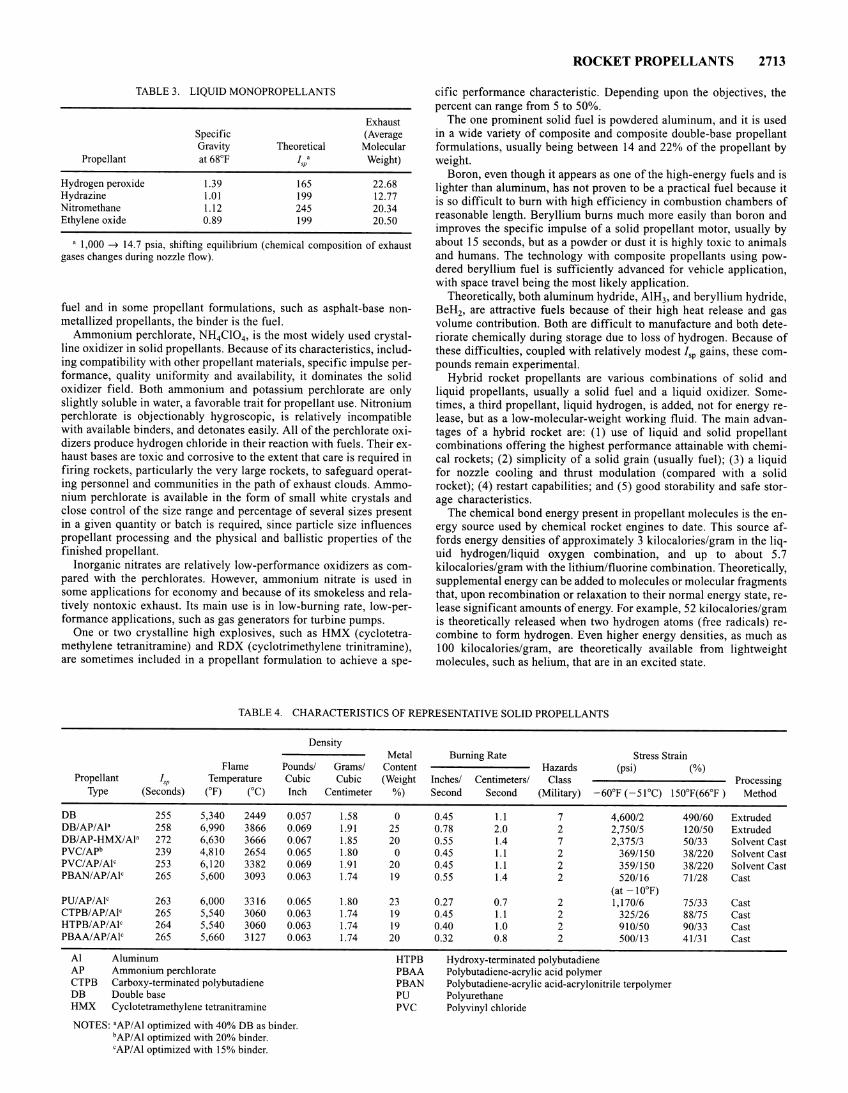
TABLE 3. LIQUID MONOPROPELLANTS
Exhaust Specific (Average Gravity Theoretical Molecular
Propellant at 68°F fs/ Weight)
Hydrogen peroxide 1.39 165 22.68 Hydrazine 1.01 199 12.77 Nitromethane 1.12 245 20.34 Ethylene oxide 0.89 199 20.50
a 1,000 ~ 14.7 psia, shifting equilibrium (chemical composition of exhaust gases changes during nozzle flow).
fuel and in some propellant formulations, such as asphalt-base nonmetallized propellants, the binder is the fuel.
Ammonium perchlorate, NH4Cl04 , is the most widely used crystalline oxidizer in solid propellants. Because of its characteristics, including compatibility with other propellant materials, specific impulse performance, quality uniformity and availability, it dominates the solid oxidizer field. Both ammonium and potassium perchlorate are only slightly soluble in water, a favorable trait for propellant use. Nitronium perchlorate is objectionably hygroscopic, is relatively incompatible with available binders, and detonates easily. All of the perchlorate oxidizers produce hydrogen chloride in their reaction with fuels. Their exhaust bases are toxic and corrosive to the extent that care is required in firing rockets, particularly the very large rockets, to safeguard operating personnel and communities in the path of exhaust clouds. Ammonium perchlorate is available in the form of small white crystals and close control of the size range and percentage of several sizes present in a given quantity or batch is required, since particle size influences propellant processing and the physical and ballistic properties of the finished propellant.
Inorganic nitrates are relatively low-performance oxidizers as compared with the perchlorates. However, ammonium nitrate is used in some applications for economy and because of its smokeless and relatively nontoxic exhaust. Its main use is in low-burning rate, low-performance applications, such as gas generators for turbine pumps.
One or two crystalline high explosives, such as HMX ( cyclotetramethylene tetranitramine) and RDX ( cyclotrimethylene trinitramine ), are sometimes included in a propellant formulation to achieve a spe-
ROCKET PROPELLANTS 2713
cific performance characteristic. Depending upon the objectives, the percent can range from 5 to 50%.
The one prominent solid fuel is powdered aluminum, and it is used in a wide variety of composite and composite double-base propellant formulations, usually being between 14 and 22% of the propellant by weight.
Boron, even though it appears as one of the high-energy fuels and is lighter than aluminum, has not proven to be a practical fuel because it is so difficult to burn with high efficiency in combustion chambers of reasonable length. Beryllium burns much more easily than boron and improves the specific impulse of a solid propellant motor, usually by about 15 seconds, but as a powder or dust it is highly toxic to animals and humans. The technology with composite propellants using powdered beryllium fuel is sufficiently advanced for vehicle application, with space travel being the most likely application.
Theoretically, both aluminum hydride, AIH3, and beryllium hydride, BeH2, are attractive fuels because of their high heat release and gas volume contribution. Both are difficult to manufacture and both deteriorate chemically during storage due to loss of hydrogen. Because of these difficulties, coupled with relatively modest I,P gains, these compounds remain experimental.
Hybrid rocket propellants are various combinations of solid and liquid propellants, usually a solid fuel and a liquid oxidizer. Sometimes, a third propellant, liquid hydrogen, is added, not for energy release, but as a low-molecular-weight working fluid. The main advantages of a hybrid rocket are: (I) use of liquid and solid propellant combinations offering the highest performance attainable with chemical rockets; (2) simplicity of a solid grain (usually fuel); (3) a liquid for nozzle cooling and thrust modulation (compared with a solid rocket); (4) restart capabilities; and (5) good storability and safe storage characteristics.
The chemical bond energy present in propellant molecules is the energy source used by chemical rocket engines to date. This source affords energy densities of approximately 3 kilocalories/gram in the liquid hydrogen/liquid oxygen combination, and up to about 5.7 kilocalories/gram with the lithium/fluorine combination. Theoretically, supplemental energy can be added to molecules or molecular fragments that, upon recombination or relaxation to their normal energy state, release significant amounts of energy. For example, 52 kilocalories/gram is theoretically released when two hydrogen atoms (free radicals) recombine to form hydrogen. Even higher energy densities, as much as I 00 kilocalories/gram, are theoretically available from lightweight molecules, such as helium, that are in an excited state.
TABLE4. CHARACTERISTICS OF REPRESENTATIVE SOLID PROPELLANTS
Density Metal Burning Rate Stress Strain
Flame Pounds/ Grams/ Content Hazards (psi) (%) Propellant r\'fJ Temperature Cubic Cubic (Weight Inches/ Centimeters/ Class Processing
Type (Seconds) CF) CCC) Inch Centimeter %) Second Second (Military) -60°F (-51°C) 150°F(66°F) Method
DB 255 5,340 2449 0.057 1.58 0 0.45 1.1 7 4,600/2 490/60 Extruded DB/APIA!' 258 6,990 3866 0.069 1.91 25 0.78 2.0 2 2,750/5 120/50 Extruded DB/AP-HMX/Al' 272 6,630 3666 0.067 1.85 20 0.55 1.4 7 2,375/3 50/33 Solvent Cast PVC/APb 239 4,810 2654 0.065 1.80 0 0.45 1.1 2 369/150 38/220 Solvent Cast PVC/APIA!' 253 6,120 3382 0.069 1.91 20 0.45 1.1 2 359/150 38/220 Solvent Cast PBAN/AP/Al' 265 5,600 3093 0.063 1.74 19 0.55 1.4 2 520/16 71/28 Cast
(at -10°F) PU/AP/Al' 263 6,000 3316 0.065 1.80 23 0.27 0.7 2 1,170/6 75/33 Cast CTPB/AP/Al' 265 5,540 3060 0.063 1.74 19 0.45 1.1 2 325/26 88/75 Cast HTPB/AP/Al' 264 5,540 3060 0.063 1.74 19 0.40 1.0 2 910/50 90/33 Cast PBAA/AP/Al' 265 5,660 3127 0.063 1.74 20 0.32 0.8 2 500/13 41131 Cast
AI Aluminum HTPB Hydroxy-terminated polybutadiene AP Ammonium perchlorate PBAA Polybutadiene-acrylic acid polymer CTPB Carboxy-terminated polybutadiene PBAN Polybutadiene-acrylic acid-acrylonitrile terpolymer DB Double base PU Polyurethane HMX Cyclotetramethylene tetranitramine PVC Polyvinyl chloride
NOTES: 'API AI optimized with 40% DB as binder. hAP/A! optimized with 20% binder. 'APIA! optimized with 15% binder.
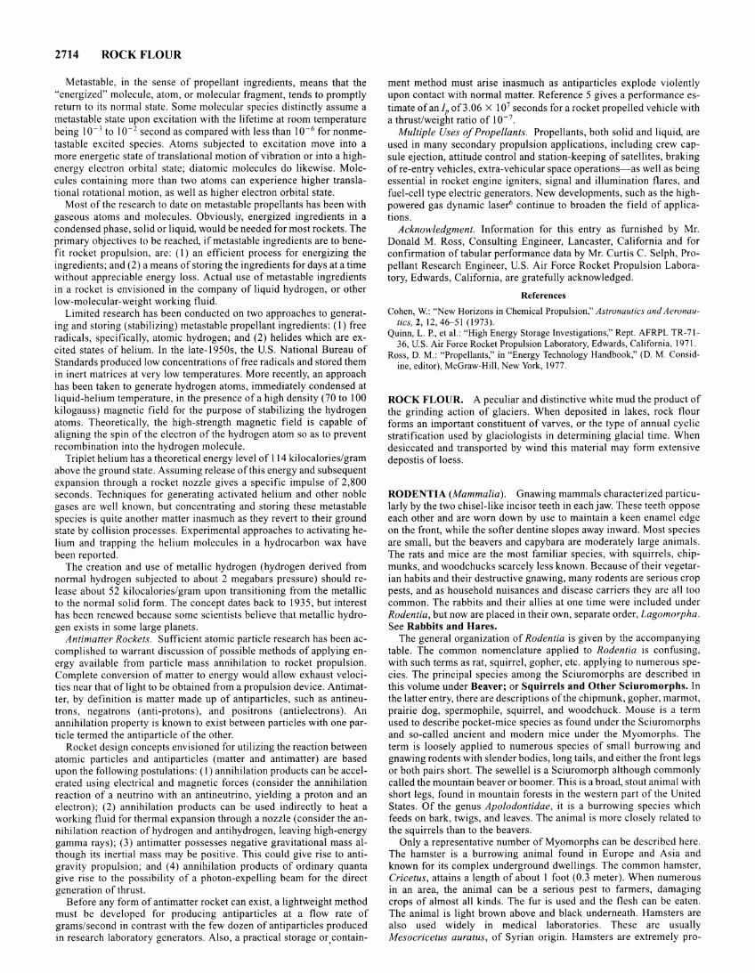
2714 ROCK FLOUR
Metastable, in the sense of propellant ingredients, means that the "energized" molecule, atom, or molecular fragment, tends to promptly return to its normal state. Some molecular species distinctly assume a metastable state upon excitation with the lifetime at room temperature being 10-3 to 10- 2 second as compared with less than 10-6 for nonmetastable excited species. Atoms subjected to excitation move into a more energetic state of translational motion of vibration or into a highenergy electron orbital state; diatomic molecules do likewise. Molecules containing more than two atoms can experience higher translational rotational motion, as well as higher electron orbital state.
Most of the research to date on metastable propellants has been with gaseous atoms and molecules. Obviously, energized ingredients in a condensed phase, solid or liquid, would be needed for most rockets. The primary objectives to be reached, if metastable ingredients are to benefit rocket propulsion, are: (I) an efficient process for energizing the ingredients; and (2) a means of storing the ingredients for days at a time without appreciable energy loss. Actual use of metastable ingredients in a rocket is envisioned in the company of liquid hydrogen, or other low-molecular-weight working fluid.
Limited research has been conducted on two approaches to generating and storing (stabilizing) metastable propellant ingredients: (I) free radicals, specifically, atomic hydrogen; and (2) helides which are excited states of helium. In the late-1950s, the U.S. National Bureau of Standards produced low concentrations of free radicals and stored them in inert matrices at very low temperatures. More recently, an approach has been taken to generate hydrogen atoms, immediately condensed at liquid-helium temperature, in the presence of a high density (70 to I 00 kilogauss) magnetic field for the purpose of stabilizing the hydrogen atoms. Theoretically, the high-strength magnetic field is capable of aligning the spin of the electron of the hydrogen atom so as to prevent recombination into the hydrogen molecule.
Triplet helium has a theoretical energy level of 114 kilocalories/gram above the ground state. Assuming release ofthis energy and subsequent expansion through a rocket nozzle gives a specific impulse of 2,800 seconds. Techniques for generating activated helium and other noble gases are well known, but concentrating and storing these metastable species is quite another matter inasmuch as they revert to their ground state by collision processes. Experimental approaches to activating helium and trapping the helium molecules in a hydrocarbon wax have been reported.
The creation and use of metallic hydrogen (hydrogen derived from normal hydrogen subjected to about 2 megabars pressure) should release about 52 kilocalories/gram upon transitioning from the metallic to the normal solid form. The concept dates back to 1935, but interest has been renewed because some scientists believe that metallic hydrogen exists in some large planets.
Antimatter Rockets. Sufficient atomic particle research has been accomplished to warrant discussion of possible methods of applying energy available from particle mass annihilation to rocket propulsion. Complete conversion of matter to energy would allow exhaust velocities near that of light to be obtained from a propulsion device. Antimatter, by definition is matter made up of antiparticles, such as antineutrons, negatrons (anti-protons), and positrons (antielectrons). An annihilation property is known to exist between particles with one particle termed the antiparticle of the other.
Rocket design concepts envisioned for utilizing the reaction between atomic particles and antiparticles (matter and antimatter) are based upon the following postulations: (I) annihilation products can be accelerated using electrical and magnetic forces (consider the annihilation reaction of a neutrino with an antineutrino, yielding a proton and an electron); (2) annihilation products can be used indirectly to heat a working fluid for thermal expansion through a nozzle (consider the annihilation reaction of hydrogen and antihydrogen, leaving high-energy gamma rays); (3) antimatter possesses negative gravitational mass although its inertial mass may be positive. This could give rise to antigravity propulsion; and ( 4) annihilation products of ordinary quanta give rise to the possibility of a photon-expelling beam for the direct generation of thrust.
Before any form of antimatter rocket can exist, a lightweight method must be developed for producing antiparticles at a flow rate of grams/second in contrast with the few dozen of antiparticles produced in research laboratory generators. Also, a practical storage or, contain-
ment method must arise inasmuch as antiparticles explode violently upon contact with normal matter. Reference 5 gives a performance estimate of an JP of 3.06 X I 07 seconds for a rocket propelled vehicle with a thrust/weight ratio of 10-7.
Multiple Uses of Propellants. Propellants, both solid and liquid, are used in many secondary propulsion applications, including crew capsule ejection, attitude control and station-keeping of satellites, braking of re-entry vehicles, extra-vehicular space operations-as well as being essential in rocket engine igniters, signal and illumination flares, and fuel-cell type electric generators. New developments, such as the highpowered gas dynamic laser6 continue to broaden the field of applications.
Acknowledgment. Information for this entry as furnished by Mr. Donald M. Ross, Consulting Engineer, Lancaster, California and for confirmation of tabular performance data by Mr. Curtis C. Selph, Propellant Research Engineer, U.S. Air Force Rocket Propulsion Laboratory, Edwards, California, are gratefully acknowledged.
References
Cohen, W.: "New Horizons in Chemical Propulsion," Astronautics and Aeronautics, 2, 12,46--51 (1973).
Quinn, L. P., eta!.: "High Energy Storage Investigations," Rept. AFRPL TR-71-36, U.S. Air Force Rocket Propulsion Laboratory, Edwards, California, 1971.
Ross, D. M.: "Propellants," in "Energy Technology Handbook," (D. M. Considine, editor), McGraw-Hill, New York, 1977.
ROCK FLOUR. A peculiar and distinctive white mud the product of the grinding action of glaciers. When deposited in lakes, rock flour forms an important constituent of varves, or the type of annual cyclic stratification used by glaciologists in determining glacial time. When desiccated and transported by wind this material may form extensive depostis of loess.
RODENTIA (Mammalia). Gnawing mammals characterized particularly by the two chisel-like incisor teeth in each jaw. These teeth oppose each other and are worn down by use to maintain a keen enamel edge on the front, while the softer dentine slopes away inward. Most species are small, but the beavers and capybara are moderately large animals. The rats and mice are the most familiar species, with squirrels, chipmunks, and woodchucks scarcely less known. Because of their vegetarian habits and their destructive gnawing, many rodents are serious crop pests, and as household nuisances and disease carriers they are all too common. The rabbits and their allies at one time were included under Rodentia, but now are placed in their own, separate order, Lagomorpha. See Rabbits and Hares.
The general organization of Rodentia is given by the accompanying table. The common nomenclature applied to Rodentia is confusing, with such terms as rat, squirrel, gopher, etc. applying to numerous species. The principal species among the Sciuromorphs are described in this volume under Beaver; or Squirrels and Other Sciuromorphs. In the latter entry, there are descriptions of the chipmunk, gopher, marmot, prairie dog, spermophile, squirrel, and woodchuck. Mouse is a term used to describe pocket-mice species as found under the Sciuromorphs and so-called ancient and modern mice under the Myomorphs. The term is loosely applied to numerous species of small burrowing and gnawing rodents with slender bodies, long tails, and either the front legs or both pairs short. The sewellel is a Sciuromorph although commonly called the mountain beaver or boomer. This is a broad, stout animal with short legs, found in mountain forests in the western part of the United States. Of the genus Apolodontidae, it is a burrowing species which feeds on bark, twigs, and leaves. The animal is more closely related to the squirrels than to the beavers.
Only a representative number of Myomorphs can be described here. The hamster is a burrowing animal found in Europe and Asia and known for its complex underground dwellings. The common hamster, Cricetus, attains a length of about I foot (0.3 meter). When numerous in an area, the animal can be a serious pest to farmers, damaging crops of almost all kinds. The fur is used and the flesh can be eaten. The animal is light brown above and black underneath. Hamsters are also used widely in medical laboratories. These are usually Mesocricetus auratus, of Syrian origin. Hamsters are extremely pro-
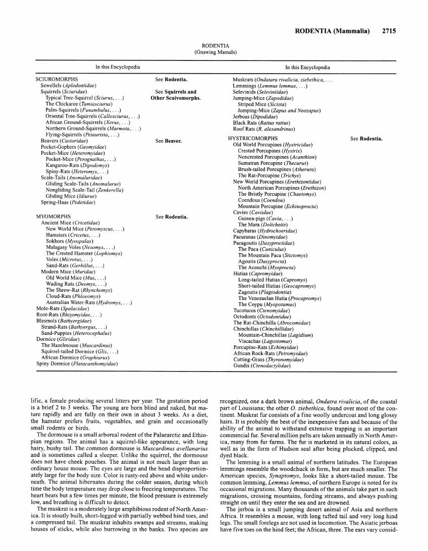
RODENTIA (Mammalia) 2715
RODENTIA (Gnawing Mamals)
In this Encyclopedia
SCIUROMORPHS Sewellels (Aplodontidae) Squirrels (Sciuridae)
Typical Tree-Squirrel (Sciurus, ... ) The Chickaree (Tamiasciurus) Palm-Squirrels (Funambulus, ... ) Oriental Tree-Squirrels (Callosciurus, . .. ) African Ground-Squirrels (Xerus, .. . ) Northern Ground-Squirrels (Marmota, . .. ) Flying-Squirrels (Petaurista, ... )
Beavers (Castoridae) Pocket-Gophers (Geomyidae) Pocket-Mice (Heteromyidae)
Pocket-Mice (Perognathus, .. . ) Kangaroo-Rats (Dipodomys) Spiny-Rats (Heteromys, .. . )
Scale-Tails (Anomaluridae) Gliding Scale-Tails (Anomalurus) Nongliding Scale-Tail (Zenkerella) Gliding Mice (ldiurus)
Spring-Haas (Pedetidae)
MYOMORPHS Ancient Mice (Cricetidae)
New World Mice (Peromyscus, .. . ) Hamsters (Cricetus, . .. ) Sokhors (Myospalax) Malagasy Voles (Nesomys, . .. ) The Crested Hamster (Lophiomys) Voles (Microtus, . .. ) Sand-Rats (Gerbil/us, ... )
Modern Mice (Muridae) Old World Mice (Mus, . .. ) Wading Rats (Deomys, .. . ) The Shrew-Rat (Rhynchomys) Cloud-Rats (Phloeomys) Australian Water-Rats (Hydromys, .. . )
Mole-Rats (Spalacidae) Root-Rats (Rhizomyidae, .. . ) Blesmols (Bathyergidae)
Strand-Rats (Bathyergus, .. . ) Sand-Puppies (Heterocephalus)
Dormice (Gliridae) The Hazelmouse (Muscardinus) Squirrel-tailed Dormice (Glis, .. . ) African Dormice (Graphiurus)
Spiny Dormice (P/atacanthomyidae)
See Rodentia.
See Squirrels and Other Scuivomorphs.
See Beaver.
See Rodentia.
lific, a female producing several litters per year. The gestation period is a brief 2 to 3 weeks. The young are born blind and naked, but mature rapidly and are fully on their own in about 3 weeks. As a diet, the hamster prefers fruits, vegetables, and grain and occasionally small rodents or birds.
The dormouse is a small arboreal rodent of the Palaearctic and Ethiopian regions. The animal has a squirrel-like appearance, with long hairy, bushy tail. The common dormouse is Muscardinus avellanarius and is sometimes called a sleeper. Unlike the squirrel, the dormouse does not have cheek pouches. The animal is not much larger than an ordinary house mouse. The eyes are large and the head disproportionately large for the body size. Color is rusty-red above and white underneath. The animal hibernates during the colder season, during which time the body temperature may drop close to freezing temperatures. The heart beats but a few times per minute, the blood pressure is extremely low, and breathing is difficult to detect.
The muskrat is a moderately large amphibious rodent ofNorth America. It is stoutly built, short-legged with partially webbed hind toes, and a compressed tail. The muskrat inhabits swamps and streams, making houses of sticks, while also burrowing in the banks. Two species are
In this Encyclopedia
Muskrats ( Ondatara rivalicia, ziebethica, ... Lemmings (Lemmus lemmus, .. . ) Selevinids (Seleviniidae) Jumping-Mice (Zapodidae)
Striped Mice (Sicista) Jumping-Mice (Zapus and Neozapus)
Jerboas (Dipodidae) Black Rats (Rattus rattus) Roof Rats (R. alexandrinus)
HYSTRICOMORPHS Old World Porcupines (Hystricidae)
Crested Porcupines (Hystrix) Noncrested Porcupines (Acanthion) Sumatran Porcupine (Thecurus) Brush-tailed Porcupines (Atherura) The Rat-Porcupine (Trichys)
New World Porcupines (Erethizontidae) North American Porcupines (Erethizon) The Bristly Porcupine (Chaetomys) Coendous (Coendou) Mountain Porcupine (Echinoprocta)
Cavies (Caviidae) Guinea-pigs (Cavia, ... ) The Mara (Dolichotis)
Capybaras (Hydrochoeridae) Pacuranas (Dinomyidae) Pacagoutis (Dasyproctidae)
The Paca (Cuniculus) The Mountain Paca (Stictomys) Agoutis (Dasyprocta) The Acouchi (Myoprocta)
Hutias (Capromyidae) Long-tailed Hutias (Capromys) Short-tailed Hutias (Geocapromys) Zagoutis (P/agiodontia) The Venezuelan Hutia (Procapromys) The Coypu (Myopotamus)
Tucotucos (Ctenomyidae) Octodonts (Octodontidae) The Rat-Chinchilla (Abrocomidae) Chinchillas (Chinchillidae)
Mountain-Chinchillas (Lagidium) Viscachas (Lagostomus)
Porcupine-Rats (Echimyidae) African Rock-Rats (Petromyidae) Cutting-Grass (Thyronomyidae) Gun dis ( Ctenodactylidae)
See Rodentia.
recognized, one a dark brown animal, Ondatra rivalicia, of the coastal part of Louisiana; the other 0. ziebethica, found over most of the continent. Muskrat fur consists of a fine woolly undercoat and long glossy hairs. It is probably the best of the inexpensive furs and because of the ability of the animal to withstand extensive trapping is an important commercial fur. Several million pelts are taken annually in North America, many from fur farms. The fur is marketed in its natural colors, as well as in the form of Hudson seal after being plucked, clipped, and dyed black.
The lemming is a small animal of northern latitudes. The European lemmings resemble the woodchuck in form, but are much smaller. The American species, Synaptomys, looks like a short-tailed mouse. The common lemming, Lemmus lemmus, of northern Europe is noted for its occasional migrations. Many thousands of the animals take part in such migrations, crossing mountains, fording streams, and always pushing straight on until they enter the sea and are drowned.
The jerboa is a small jumping desert animal of Asia and northern Africa. It resembles a mouse, with long tufted tail and very long hind legs. The small forelegs are not used in locomotion. The Asiatic jerboas have five toes on the hind feet; the African, three. The ears vary consid-
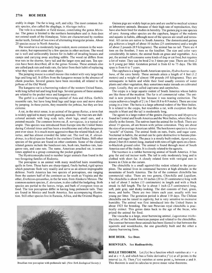
2716 ROE DEER
erably in shape. The fur is long, soft, and silky. The most common Asiatic species, also called the alagdaga, is Alactaga indica.
The vole is a meadow or field mouse, constituting the genus Microtus. The genus is limited to the northern hemisphere and in Asia does not extend south of the Himalayas. Voles are characterized by rootless molar teeth, formed of two rows of alternating triangular prisms. About 20 species occur in North America.
The wood rat is a moderately large rodent, more common in the western states, but represented by a few species in other sections. The wood rat is well and unfavorably known for its habit of invading houses and camps and carrying away anything edible. The wood rat differs from true rats in the shorter, furry tail and the larger eyes and ears. Ten species have been described, all in the genus Netoma. These animals also are called pack rats and trade rats, the latter from their habit of replacing what they take with some other object.
The jumping mouse is a small mouse-like rodent with very large hind legs and long tail. It differs from the kangaroo mouse in the absence of cheek pouches. Several genera have been recorded, all related to the jerboas of the Old World.
The kangaroo rat is a burrowing rodent of the western United States, with long tufted tail and long hind legs. Several genera of these animals are related to the pocket mice and kangaroo mice.
The gerbil is a small burrowing animal of Asia and Africa. Gerbils resemble rats, but have long hind legs and large eyes and move about by jumping. In these points, they resemble the jerboas, but they are less extreme.
A rat, in the strict sense, is an animal of the genus Rattus, a term that is widely applied to many small gnawing animals. The true rats are dullcolored animals with long scaly tails, short legs, small ears, and a pointed muzzle. The common brown rat, R. norvegicus, is a typical example. This species was introduced from Europe into the United States during Colonial times and has been a troublesome and often dangerous pest ever since. It is much more aggressive than the related black rat, R. rattus, and has almost crowded the latter out. The roof rat, R. alexandrinus, is a third species found in the southern United States. Still other species of the genus are found on other contients. Some of the closely related genera include the bandicoot rats, bush rats, bamboo rats, kangaroo rats, and cane rats. The name, American pouched rat, is sometimes applied to a group containing the pocket gopher.
The Hystricomorphs tend to number larger animals than found in the two foregoing familes of Rodentia.
The porcupine is an animal with many modified hairs resembling quills in form. These hairs are sharp-tipped, finely barbed, rigid spines which penetrate flesh very readily and serve as an almost impregnable defense. North America has two species of porcupines, one ranging from the eastern half of the continent as far south as Virginia and the other, Erethizon epixanthus, in the far west, from Alaska to Mexico. The common eastern species, E. dorsatum, is also called the hedgehog. Both species are partial to the leaves, twigs, and bark of evergreen trees as food . The tree porcupines differ in having long prehensile tails. They are found in Mexico and South America. See accompanying illustration. Still other species live in Eurasia, Africa, and the Oriental Region.
Brazilian tree porcupine with prehensile tail. (New York Zoological Society.)
Guinea pigs are widely kept as pets and are useful to medical science as laboratory animals. Because of their high rate of reproduction, they have also been bred for studies in heredity. The guinea pig is one species of cavy. Among other species are the capybara, largest of the rodents and aquatic in habits, although most of the species are small and terrestrial. All cavies are native to South America. The domesticated guinea pig achieves a length of about I 0 inches (25 centimeters) and a weight of about 2 pounds (0.9 kilograms). The animal has no tail. There are 4 toes on the forefeet; 5 toes on the hindfeet. The size and color vary considerably. In nature, the animal feeds on grass and vegetables. As a pet, the animal will consume some kinds of dog or cat food, but requires a lot of water. They can be bred 2 to 3 times per year. There are from 2 to 8 young per litter. Gestation period is from 63 to 75 days. The life span is from 6 to 7 years.
The capybara is a large South American species, Hydrochoerus capybara, of the cava family. These animals attain a length of 4 feet ( 1.2 meters) and a weight of almost 100 pounds (45 kilograms). They are semiaquatic in habits and while their food usually consists of water plants and other vegetation, they sometimes make inroads on cultivated crops. Locally, they are called capivaras and carpinchos.
The coypu is a large aquatic rodent of South America whose habits are like those of the muskrat. The fur is of commercial value. The animal is now protected by law because it was nearing extinction. The coypu achieves a length of2 ~to 3 feet (0.8 to 0.9 meter). There are nine young in a litter. The hutia is a large arboreal rodent of the West Indies. It is related to the coypu, but resembles a rat, with exception that the muzzle is blunt and the tail is moderately long.
The agouti is a large rodent of the genera Dasyprocta and Myoprocta found in Central and South America and the West Indies, where they live chiefly in the forests. The natives hunt the animal for its flesh. There are about 15 species, all are brown with yellow coloration. They are about the size of an average American rabbit. The best known species is Azaras "acuchi" of Guinea. The animal feeds on nuts, fruits, and sugar cane. Nocturnal in habits, the animal can be quite destructive to banana plantations and sugar fields. The paca is a stoutly built rodent, Agouti paca, about 2 feet (0.6 meter) long, marked with rows oflight spots on a fawnto-blackish ground color. The animal is found through most of South America east of the Andes. It is closely related to the agoutis.
The tucotuco is a ratlike burrowing animal of South America. It has gray fur and red incisor teeth. The tail is only moderately long and is clothed with short fur. A closely related form with vestigial ears is known in Chile as the cururo.
The chinchilla is a small squirrel-like rodent related to the porcupines. The animal lives in communal burrows at high altitudes in the mountains of South America. The fur of the common chinchilla has commercial value. There are two genera, Chinchilla and Lagidium. The chinchilla is about 8 to I 0 inches (20 to 25 centimeters) long with a tail of about 5 inches ( 13 centimeters) in length and with a black streak its full length. The fur is about I inch (2.5 centimeters) long, soft, pale gray, and dusky-looking. The diet consists of fruit, grain, moss, and herbs. There are two litters each year, usually with two young per litter. The gestation period is about II 0 days. The Chilean chinchilla can be raised in captivity, but is very sensitive to excessive humidity. The animal was first introduced into the United States in about 1923 for breeding. The rare Peruvian royal chinchilla is practically extinct. This genus dates back to the age of the Incas, who prized the animal for food.
The viscacha is a large, stout burrowing animal, Lagostomus trichodactylus, of the South American pampas and related to the chinchillas. The contrast between these animals has been likened to that between the squirrels and woodchucks, the one gracefully built and the other a clumsy burrowing form.
ROE DEER. See Deer.
ROENTGEN. See Radioactivity.
ROLLE THEOREM. Letf(x) be a function which vanishes at x = a and atx = b, and which has a finite derivativef'(x) at all points in the interval (a, b). Thenf'(x) vanishes at some point x0 between a and b. This theorem is used in calculus to prove mean value theorems.
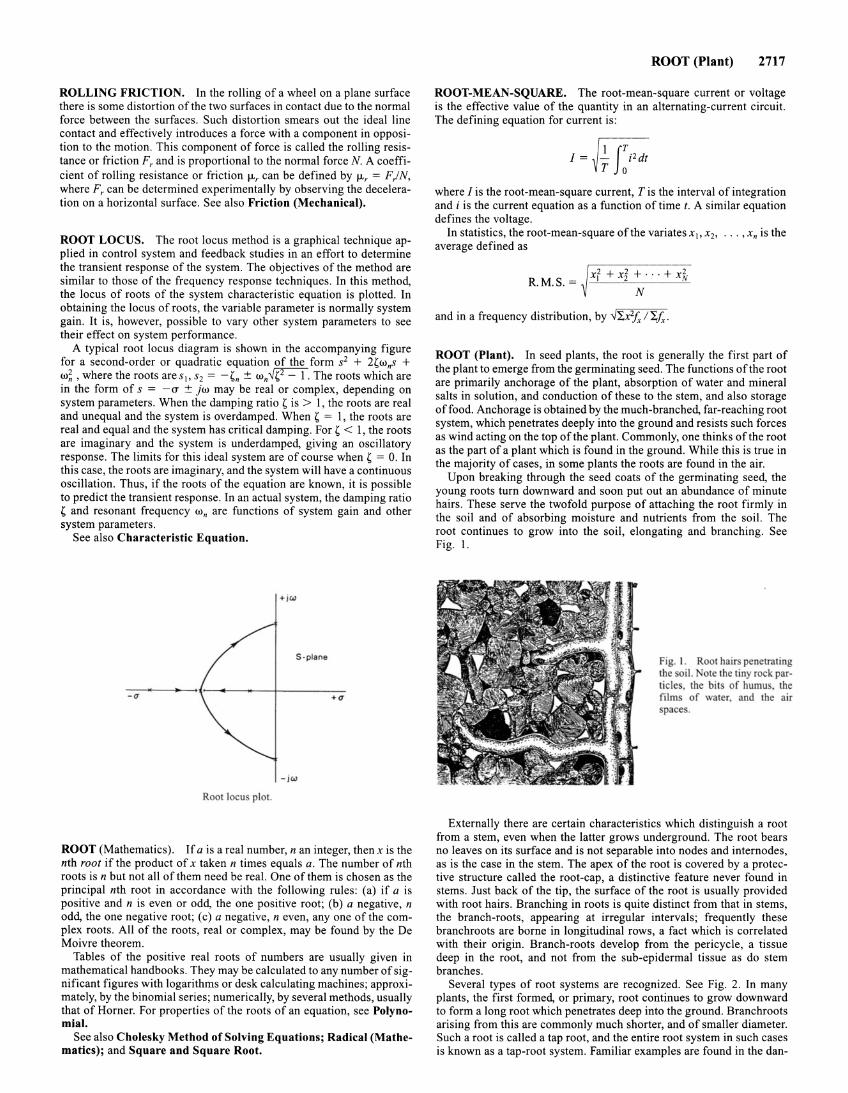
ROLLING FRICTION. In the rolling of a wheel on a plane surface there is some distortion of the two surfaces in contact due to the normal force between the surfaces. Such distortion smears out the ideal line contact and effectively introduces a force with a component in opposition to the motion . This component of force is called the rolling resistance or friction Fr and is proportional to the normal force N. A coefficient of rolling resistance or friction 1-lr can be defined by 1-lr = F ) N, where Fr can be determined experimentally by observing the deceleration on a horizontal surface. See also Friction (Mechanical).
ROOT LOCUS. The root locus method is a graphical technique applied in control system and feedback studies in an effort to determine the transient response of the system. The objectives of the method are similar to those of the frequency response techniques. In this method, the locus of roots of the system characteristic equation is plotted. In obtaining the locus of roots, the variable parameter is normally system gain. It is, however, possible to vary other system parameters to see their effect on system performance.
A typical root locus diagram is shown in the accompanying figure for a second-order or quadratic equation of the form s2 + 2,w.s + w~, where the roots ares 1, s2 = _,n ± w.~. The roots which are in the form of s = -a ± jw may be real or complex, depending on system parameters. When the damping ratio ' is > 1, the roots are real and unequal and the system is overdamped. When ' = 1, the roots are real and equal and the system has critical damping. For' < 1, the roots are imaginary and the system is underdamped, giving an oscillatory response . The limits for this ideal system are of course when ' = 0. In this case, the roots are imaginary, and the system will have a continuous oscillation. Thus, if the roots of the equation are known, it is possible to predict the transient response. In an actual system, the damping ratio ' and resonant frequency w. are functions of system gain and other system parameters .
See also Characteristic Equation.
+JW
S · plane
-(1 +u
-jw
Root locus plot.
ROOT (Mathematics). If a is a real number, nan integer, then xis the nth root if the product of x taken n times equals a. The number of nth roots is n but not all of them need be real. One of them is chosen as the principal nth root in accordance with the following rules: (a) if a is positive and n is even or odd, the one positive root; (b) a negative, n odd, the one negative root; (c) a negative, n even, any one of the complex roots. All of the roots, real or complex, may be found by the De Moivre theorem.
Tables of the positive real roots of numbers are usually given in mathematical handbooks. They may be calculated to any number of significant figures with logarithms or desk calculating machines; approximately, by the binomial series; numerically, by several methods, usually that of Horner. For properties of the roots of an equation, see Polynomial.
See also Cholesky Method of Solving Equations; Radical (Mathematics); and Square and Square Root.
ROOT (Plant) 2717
ROOT-MEAN-SQUARE. The root-mean-square current or voltage is the effective value of the quantity in an alternating-current circuit. The defining equation for current is :
where I is the root-mean-square current, Tis the interval of integration and i is the current equation as a function of timet. A similar equation defines the voltage.
In statistics, the root-mean-square of the variates x1, x2, .. . , x. is the average defined as
~ x2 + x2 + . . . + x2 R. M.S. = I 2 N
N
and in a frequency distribution, by ..J"'2.x2fx l 'i,fx.
ROOT (Plant). In seed plants, the root is generally the first part of the plant to emerge from the germinating seed. The functions of the root are primarily anchorage of the plant, absorption of water and mineral salts in solution, and conduction of these to the stem, and also storage of food. Anchorage is obtained by the much-branched, far-reaching root system, which penetrates deeply into the ground and resists such forces as wind acting on the top ofthe plant. Commonly, one thinks of the root as the part of a plant which is found in the ground. While this is true in the majority of cases, in some plants the roots are found in the air.
Upon breaking through the seed coats of the germinating seed, the young roots turn downward and soon put out an abundance of minute hairs. These serve the twofold purpose of attaching the root firmly in the soil and of absorbing moisture and nutrients from the soil. The root continues to grow into the soil, elongating and branching. See Fig. I.
Fig. I. Root hairs penetrating the oil. ote the tiny rock particle . the bit of humu , the film of water, and the air pace .
Externally there are certain characteristics which distinguish a root from a stem, even when the latter grows underground. The root bears no leaves on its surface and is not separable into nodes and internodes, as is the case in the stem. The apex of the root is covered by a protective structure called the root-cap, a distinctive feature never found in stems. Just back of the tip, the surface of the root is usually provided with root hairs. Branching in roots is quite distinct from that in stems, the branch-roots, appearing at irregular intervals; frequently these branchroots are borne in longitudinal rows, a fact which is correlated with their origin. Branch-roots develop from the pericycle, a tissue deep in the root, and not from the sub-epidermal tissue as do stem branches.
Several types of root systems are recognized. See Fig. 2. In many plants, the first formed, or primary, root continues to grow downward to form a long root which penetrates deep into the ground. Branchroots arising from this are commonly much shorter, and of smaller diameter. Such a root is called a tap root, and the entire root system in such cases is known as a tap-root system. Familiar examples are found in the dan-
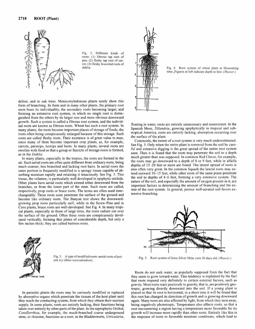
2718 ROOT (Plant)
Fig. 2. Different kind of root : (I) fibrou tap root of pea; (2) neshy tap root of carrot; (3) neshy fo cicled roots of dahlia.
delion, and in oak trees. Monocotyledonous plants rarely show this form of branching. In them and in many other plants, the primary root soon loses its individuality, the secondary roots becoming larger, and forming an extensive root system, in which no single root is distinguished from the others by its larger size and more obvious downward growth. Such a system is called a fibrous root system, and the individual roots are known as fibrous roots. Wheat has such a root system. In many plants, the roots become important places of storage offoods, the roots often being conspicuously enlarged because of this storage. Such roots are called fleshy roots. Their existence is of great value to man, since many of them become important crop plants, as, for example, carrots, parsnips, turnips and beets. In many plants, several roots are swollen with food so that a group or fascicle of storage roots is formed, as in the Dahlia.
In many plants, especially in the tropics, the roots are formed in the air. Such aerial roots are often quite different from ordinary roots, being much coarser, less branched and lacking root hairs. In aerial roots the outer portion is frequently modified to a spongy tissue capable of absorbing moisture rapidly and retaining it tenaciously. See Fig. 3. This tissue, the velamen, is particularly well developed in epiphytic orchids. Other plants have aerial roots which extend either downward from the branches, or from the lower part of the stem. Such roots are called, respectively, prop roots or brace roots. The terms are often used interchangeably. These roots soon penetrate the surface of the ground and become like ordinary roots. The Banyan tree shows the downwardgrowing prop roots particularly well, while in the Screw-Pine and in Corn plants, brace roots are well-developed. See Fig. 4. In many tropical plants, especially in those of large trees, the roots radiate out over the surface of the ground. Often these roots are conspicuously developed vertically, forming thin plates of considerable depth, but only a few inches thick; they are called buttress roots.
Fig. 3. A type of modified root - aerial root of poison ivy (Rhu toxicodendron).
In parasitic plants the roots may be curiously modified or replaced by absorptive organs which penetrate the tissues of the host plant until they reach the conducting system, from which they obtain their nutrient supply. In some plants, roots are entirely lacking, their functions being taken over entirely by other parts of the plant. In the saprophytic Orchid, Corallorrhiza, for example, the much-branched coarse underground stem, or rhizome, functions as a root; in the Bladderworts, Utricularia,
5
Fig. 4 . Root y tern of wheat plant at blo oming time igure at left indicate depth in feet. (Wea ver.)
floating in water, roots are entirely unnecessary and nonexistent. In the Spanish Moss, Tillandsia, growing epiphytically in tropical and subtropical America, roots are entirely lacking, absorption occurring over the surface of the plant.
Commonly, the extent of a root system is very much underestimated. See Fig. 5. Only when the entire plant is removed from the soil by careful and extensive digging is the great spread of the entire root system seen. Then it is found that the roots may penetrate the soil to a depth much greater than was supposed. In common Red Clover, for example, the roots may go downward to a depth of 8 or 9 feet, while in alfalfa depths of 15-20 feet or more are found. The lateral spread of roots is also often very great. In the common Squash the lateral roots may extend outward 10- 15 feet, while other roots of the same plane penetrate the soil to depths of 4- 6 feet, forming a very extensive system. The nature of the soil, and especially the amount of oxygen present in it, are important factors in determining the amount of branching and the extent of the root system. In general, porous well-aerated soil favors extensive branching.
Fig. 5. Root y tern of Iowa ilver Mine corn 36 days old. (Wea1•er.)
Roots do not seek water, as popularly supposed from the fact that they seem to grow toward water. This tendency is explained by the fact that roots respond very definitely to certain external factors, such as gravity. Most roots react positively to gravity, that is, are positively geotropic, growing directly downward into the soil. If a young plant is placed so that its root is horizontal, in a short time it will be found that this root has changed its direction of growth and is growing downward again. Many roots are also affected by light, from which they turn away, being negatively phototropic. Temperature also affects roots, so that a root encountering a region having a temperature more favorable for its growth will increase more rapidly than other roots. Entirely like this is the response of roots to favorable moisture conditions, which lead to
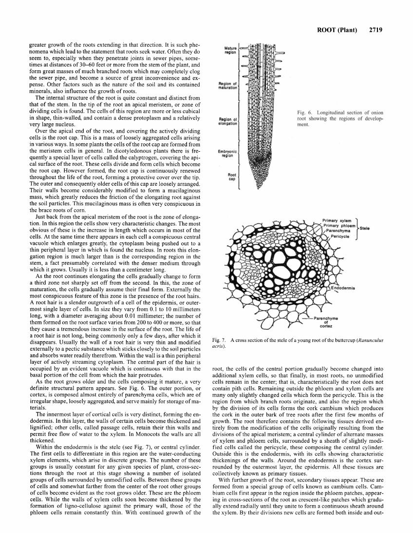
greater growth of the roots extending in that direction. It is such phenomena which lead to the statement that roots seek water. Often they do seem to, especially when they penetrate joints in sewer pipes, sometimes at distances of 30-60 feet or more from the stem of the plant, and form great masses of much branched roots which may completely clog the sewer pipe, and become a source of great inconvenience and expense. Other factors such as the nature of the soil and its contained minerals, also influence the growth of roots.
The internal structure of the root is quite constant and distinct from that of the stem. In the tip of the root an apical meristem, or zone of dividing cells is found. The cells of this region are more or less cubical in shape, thin-walled, and contain a dense protoplasm and a relatively very large nucleus.
Over the apical end of the root, and covering the actively dividing cells is the root cap. This is a mass of loosely aggregated cells arising in various ways. In some plants the cells of the root cap are formed from the meristem cells in general. In dicotyledonous plants there is frequently a special layer of cells called the calyptrogen, covering the apical surface of the root. These cells divide and form cells which become the root cap. However formed, the root cap is continuously renewed throughout the life of the root, forming a protective cover over the tip. The outer and consequently older cells of this cap are loosely arranged. Their walls become considerably modified to form a mucilaginous mass, which greatly reduces the friction of the elongating root against the soil particles. This mucilaginous mass is often very conspicuous in the brace roots of corn.
Just back from the apical meristem of the root is the zone of elongation. In this region the cells show very characteristic changes. The most obvious of these is the increase in length which occurs in most of the cells. At the same time there appears in each cell a conspicuous central vacuole which enlarges greatly, the cytoplasm being pushed out to a thin peripheral layer in which is found the nucleus. In roots this elongation region is much larger than is the corresponding region in the stem, a fact presumably correlated with the denser medium through which it grows. Usually it is less than a centimeter long.
As the root continues elongating the cells gradually change to form a third zone not sharply set off from the second. In this, the zone of maturation, the cells gradually assume their final form. Externally the most conspicuous feature of this zone is the presence of the root hairs. A root hair is a slender outgrowth of a cell of the epidermis, or outermost single layer of cells . In size they vary from 0.1 to 10 millimeters long, with a diameter averaging about 0.01 millimeter; the number of them formed on the root surface varies from 200 to 400 or more, so that they cause a tremendous increase in the surface of the root. The life of a root hair is not long, being commonly only a few days, after which it disappears . Usually the wall of a root hair is very thin and modified externally to a pectic substance which sticks closely to the soil particles and absorbs water readily therefrom. Within the wall is a thin peripheral layer of actively streaming cytoplasm. The central part of the hair is occupied by an evident vacuole which is continuous with that in the basal portion of the cell from which the hair protrudes.
As the root grows older and the cells composing it mature, a very definite structural pattern appears. See Fig. 6. The outer portion, or cortex, is composed almost entirely of parenchyma cells, which are of irregular shape, loosely aggregated, and serve mainly for storage of materials .
The innermost layer of cortical cells is very distinct, forming the endodermis. In this layer, the walls of certain cells become thickened and lignified; other cells, called passage cells, retain their thin walls and permit free flow of water to the xylem. In Monocots the walls are all thickened.
Within the endodermis is the stele (see Fig. 7), or central cylinder. The first cells to differentiate in this region are the water-conducting xylem elements, which arise in discrete groups. The number of these groups is usually constant for any given species of plant, cross-sections through the root at this stage showing a number of isolated groups of cells surrounded by unmodified cells. Between these groups of cells and somewhat farther from the center of the root other groups of cells become evident as the root grows older. These are the phloem cells. While the walls of xylem cells soon become thickened by the formation of ligno-cellulose against the primary wall , those of the phloem cells remain constantly thin . With continued growth of the
Region ot maturation
Reg ion ot elongation
Embryonic reg ion
Root cep
ROOT (Plant) 2719
Fig. 6. Longitudinal ection of onion root howing the region of development.
Fig. 7. A cross section of the stele of a young root of the buttercup (Ranunculus acris) .
root, the cells of the central portion gradually become changed into additional xylem cells, so that finally, in most roots, no unmodified cells remain in the center; that is, characteristically the root does not contain pith cells. Remaining outside the phloem and xylem cells are many only slightly changed cells which form the pericycle. This is the region from which branch roots originate, and also the region which by the division of its cells forms the cork cambium which produces the cork in the outer bark of tree roots after the first few months of growth. The root therefore contains the following tissues derived entirely from the modification of the cells originally resulting from the divisions of the apical meristem; a central cylinder of alternate masses of xylem and phloem cells, surrounded by a sheath of slightly modified cells called the pericycle, these composing the central cylinder. Outside this is the endodermis, with its cells showing characteristic thickenings of the walls. Around the endodermis is the cortex surrounded by the outermost layer, the epidermis. All these tissues are collectively known as primary tissues.
With further growth of the root, secondary tissues appear. These are formed from a special group of cells known as cambium cells . Cambium cells first appear in the region inside the phloem patches, appearing in cross-sections of the root as crescent-like patches which gradually extend radially until they unite to form a continuous sheath around the xylem. By their divisions new cells are formed both inside and out-
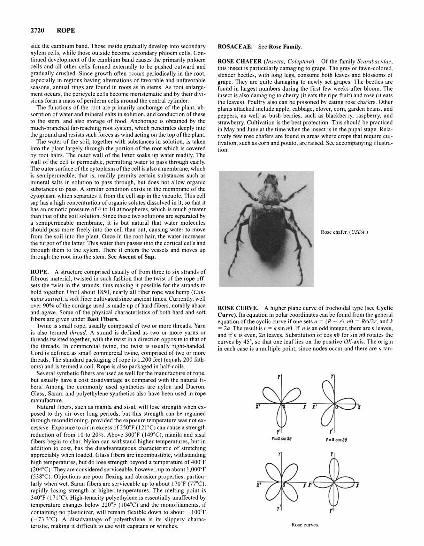
2720 ROPE
side the cambium band. Those inside gradually develop into secondary xylem cells, while those outside become secondary phloem cells. Continued development of the cambium band causes the primarily phloem cells and all other cells formed externally to be pushed outward and gradually crushed. Since growth often occurs periodically in the root, especially in regions having alternations of favorable and unfavorable seasons, annual rings are found in roots as in stems. As root enlargement occurs, the pericycle cells become meristematic and by their divisions form a mass of periderm cells around the central cylinder.
The functions of the root are primarily anchorage of the plant, absorption of water and mineral salts in solution, and conduction of these to the stem, and also storage of food. Anchorage is obtained by the much-branched far-reaching root system, which penetrates deeply into the ground and resists such forces as wind acting on the top of the plant.
The water of the soil, together with substances in solution, is taken into the plant largely through the portion of the root which is covered by root hairs. The outer wall of the latter soaks up water readily. The wall of the cell is permeable, permitting water to pass through easily. The outer surface of the cytoplasm of the cell is also a membrane, which is semipermeable, that is, readily permits certain substances such as mineral salts in solution to pass through, but does not allow organic substances to pass. A similar condition exists in the membrane of the cytoplasm which separates it from the cell sap in the vacuole. This cell sap has a high concentration of organic solutes dissolved in it, so that it has an osmotic pressure of 4 to 10 atmospheres, which is much greater than that of the soil solution. Since these two solutions are separated by a semipermeable membrane, it is but natural that water molecules should pass more freely into the cell than out, causing water to move from the soil into the plant. Once in the root hair, the water increases the turgor of the latter. This water then passes into the cortical cells and through them to the xylem. There it enters the vessels and moves up through the root into the stem. See Ascent of Sap.
ROPE. A structure comprised usually of from three to six strands of fibrous material, twisted in such fashion that the twist of the rope offsets the twist in the strands, thus making it possible for the strands to hold together. Until about 1850, nearly all fiber rope was hemp (Cannabis sativa), a soft fiber cultivated since ancient times. Currently, well over 90% of the cordage used is made up of hard fibers, notably abaca and agave. Some of the physical characteristics of both hard and soft fibers are given under Bast Fibers.
Twine is small rope, usually composed of two or more threads. Yarn is also termed thread. A strand is defined as two or more yarns or threads twisted together, with the twist in a direction opposite to that of the threads. In commercial twine, the twist is usually right-handed. Cord is defined as small commercial twine, comprised of two or more threads. The standard packaging of rope is 1 ,200 feet (equals 200 fathoms) and is termed a coil. Rope is also packaged in half-coils.
Several synthetic fibers are used as well for the manufacture of rope, but usually have a cost disadvantage as compared with the natural fibers. Among the commonly used synthetics are nylon and Dacron, Glass, Saran, and polyethylene synthetics also have been used in rope manufacture.
Natural fibers, such as manila and sisal, will lose strength when exposed to dry air over long periods, but this strength can be regained through reconditioning, provided the exposure temperature was not excessive. Exposure to air in excess of250°F (121 °C) can cause a strength reduction of from 10 to 20%. Above 300°F (149°C), manila and sisal fibers begin to char. Nylon can withstand higher temperatures, but in addition to cost, has the disadvantageous characteristic of stretching appreciably when loaded. Glass fibers are incombustible, withstanding high temperatures, but do lose strength beyond a temperature of 400°F (204°C). They are considered serviceable, however, up to about 1 ,000°F (538°C). Objections are poor flexing and abrasion properties, particularly when wet. Saran fibers are serviceable up to about 170°F (77°C), rapidly losing strength at higher temperatures. The melting point is 340°F ( 171 °C). High-tenacity polyethylene is essentially unaffected by temperature changes below 220°F (I 04°C) and the monofilaments, if containing no plasticizer, will remain flexible down to about - 1 00°F ( -73 .3°C). A disadvantage of polyethylene is its slippery characteristic, making it difficult to use with capstans or winches.
ROSACEAE. See Rose Family.
ROSE CHAFER (Insecta, Coleptera). Of the family Scarabacidae, this insect is particularly damaging to grape. The gray or fawn-colored, slender beetles, with long legs, consume both leaves and blossoms of grape. They are quite damaging to newly set grapes. The beetles are found in largest numbers during the first few weeks after bloom. The insect is also damaging to cherry (it eats the ripe fruit) and rose (it eats the leaves). Poultry also can be poisoned by eating rose chafers. Other plants attacked include apple, cabbage, clover, corn, garden beans, and peppers, as well as bush berries, such as blackberry, raspberry, and strawberry. Cultivation is the best protection. This should be practiced in May and June at the time when the insect is in the pupal stage. Relatively few rose chafers are found in areas where crops that require cultivation, such as corn and potato, are raised. See accompanying illustration.
Rose chafer. (USDA.)
ROSE CURVE. A higher plane curve oftrochoidal type (see Cyclic Curve). Its equation in polar coordinates can be found from the general equation of the cyclic curve if one sets a = (R- r), n9 = R¢>/2r, and k = 2a. The result is r = k sin n9. If n is an odd integer, there are n leaves, and if n is even, 2n leaves. Substitution of cos ne for sin ne rotates the curves by 45°, so that one leaf lies on the positive OX-axis. The origin in each case is a multiple point, since nodes occur and there are n tan-
r r
X' l
r' r=a sin 3B r:a cos39
l ' X
Rose curves.
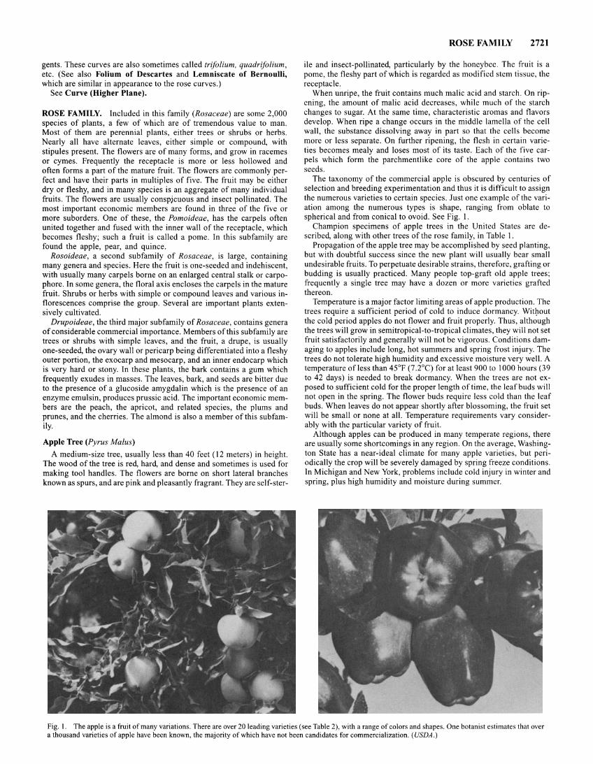
gents. These curves are also sometimes called trifolium, quadrifolium, etc. (See also Folium of Descartes and Lemniscate of Bernoulli, which are similar in appearance to the rose curves.)
See Curve (Higher Plane).
ROSE FAMILY. Included in this family (Rosaceae) are some 2,000 species of plants, a few of which are of tremendous value to man. Most of them are perennial plants, either trees or shrubs or herbs. Nearly all have alternate leaves, either simple or compound, with stipules present. The flowers are of many forms, and grow in racemes or cymes. Frequently the receptacle is more or less hollowed and often forms a part of the mature fruit. The flowers are commonly perfect and have their parts in multiples of five. The fruit may be either dry or fleshy, and in many species is an aggregate of many individual fruits. The flowers are usually conspjcuous and insect pollinated. The most important economic members are found in three of the five or more suborders. One of these, the Pomoideae, has the carpels often united together and fused with the inner wall of the receptacle, which becomes fleshy; such a fruit is called a pome. In this subfamily are found the apple, pear, and quince.
Rosoideae, a second subfamily of Rosaceae, is large, containing many genera and species. Here the fruit is one-seeded and indehiscent, with usually many carpels borne on an enlarged central stalk or carpophore. In some genera, the floral axis encloses the carpels in the mature fruit. Shrubs or herbs with simple or compound leaves and various inflorescences comprise the group. Several are important plants extensively cultivated.
Drupoideae, the third major subfamily of Rosaceae, contains genera of considerable commercial importance. Members of this subfamily are trees or shrubs with simple leaves, and the fruit, a drupe, is usually one-seeded, the ovary wall or peri carp being differentiated into a fleshy outer portion, the exocarp and mesocarp, and an inner endocarp which is very hard or stony. In these plants, the bark contains a gum which frequently exudes in masses. The leaves, bark, and seeds are bitter due to the presence of a glucoside amygdalin which is the presence of an enzyme emulsin, produces prussic acid. The important economic members are the peach, the apricot, and related species, the plums and prunes, and the cherries. The almond is also a member of this subfamily.
Apple Tree (Pyrus Malus)
A medium-size tree, usually less than 40 feet (12 meters) in height. The wood of the tree is red, hard, and dense and sometimes is used for making tool handles. The flowers are borne on short lateral branches known as spurs, and are pink and pleasantly fragrant. They are self-ster-
ROSE FAMILY 2721
ile and insect-pollinated, particularly by the honeybee. The fruit is a pome, the fleshy part of which is regarded as modified stem tissue, the receptacle.
When unripe, the fruit contains much malic acid and starch. On ripening, the amount of malic acid decreases, while much of the starch changes to sugar. At the same time, characteristic aromas and flavors develop. When ripe a change occurs in the middle lamella of the cell wall, the substance dissolving away in part so that the cells become more or less separate. On further ripening, the flesh in certain varieties becomes mealy and loses most of its taste. Each of the five carpels which form the parchmentlike core of the apple contains two seeds.
The taxonomy of the commercial apple is obscured by centuries of selection and breeding experimentation and thus it is difficult to assign the numerous varieties to certain species. Just one example of the variation among the numerous types is shape, ranging from oblate to spherical and from conical to ovoid. See Fig. I.
Champion specimens of apple trees in the United States are described, along with other trees of the rose family, in Table I.
Propagation of the apple tree may be accomplished by seed planting, but with doubtful success since the new plant will usually bear small undesirable fruits. To perpetuate desirable strains, therefore, grafting or budding is usually practiced. Many people top-graft old apple trees; frequently a single tree may have a dozen or more varieties grafted thereon.
Temperature is a major factor limiting areas of apple production. The trees require a sufficient period of cold to induce dormancy. Wit~out the cold period apples do not flower and fruit properly. Thus, although the trees will grow in semitropical-to-tropical climates, they will not set fruit satisfactorily and generally will not be vigorous. Conditions damaging to apples include long, hot summers and spring frost injury. The trees do not tolerate high humidity and excessive moisture very well. A temperature ofless than 45°F (7.2°C) for at least 900 to I 000 hours (39 to 42 days) is needed to break dormancy. When the trees are not exposed to sufficient cold for the proper length of time, the leaf buds will not open in the spring. The flower buds require less cold than the leaf buds. When leaves do not appear shortly after blossoming, the fruit set will be small or none at all. Temperature requirements vary considerably with the particular variety of fruit.
Although apples can be produced in many temperate regions, there are usually some shortcomings in any region. On the average, Washington State has a near-ideal climate for many apple varieties, but periodically the crop will be severely damaged by spring freeze conditions. In Michigan and New York, problems include cold injury in winter and spring, plus high humidity and moisture during summer.
Fig. I. The apple is a fruit of many variations. There are over 20 leading varieties (see Table 2), with a range of colors and shapes. One botanist estimates that over a thousand varieties of apple have been known, the majority of which have not been candidates for commercialization. (USDA.)

2722 ROSE FAMILY
Specimen
APPLE Common apple ( 1984)
(Malus sylvestris) Oregon crab apple ( 1971)
(Malusfusea) Sweet crab apple (1985)
(Malus coronaria) CHERRY Bitter cherry ( 1975)
(Prunus emarginata) Black cherry (1972)
(Prunus serafina) Southwestern black cherry (1982)
(Prunus serotina var. rufula) Catalina cherry ( 1978)
(Prunuslyonii) Chokecherry, Common ( 1967)
(Prunus virginiana) Chokecherry, Western (1985)
(Prunus virginiana var. melanocarpa)
Escarpment cherry (1971) (Prunus serotina var. eximia)
Hollyleaf cherry ( 1974) (Prunus ilicifolia)
Laurel cherry (1970) (Prunus caroliniana)
Laurel cherry (1985) (Co-record holder)
Mazzard cherry ( 1969) (Prunus avium)
Pin cherry (1975) (Prunus pensylvanica)
Sour cherry (1972) (Prunus cerasus)
HAWTHORN Black hawthorn (1973)
( Crataegus douglasii) Blueberry hawthorn ( 1973)
( Crataegus brachyacantha) Cockspur hawthorn (1981)
( Crataegus crus-ga/li) Columbia hawthorn (1975)
( Crataegus columbiana) Dotted hawthorn ( 1979)
( Crataegus puncta/a) Downy hawthorn (1972)
( Crataegus mollis) Fanleaf hawthorn ( 1966)
( Crataegus fabella/a) Fleshy hawthorn (1982)
( Crataegus succulenta) Glossy hawthorn (1972)
( Crataegus nitida) Green hawthorn ( 1981 )
( Crataegus viridis) Hills hawthorn (1954)
( Crataegus hilli) Kansas hawthorn (1972)
(Crataegus coccinioides) Littlehip hawthorn ( 1980) One-seed hawthorn ( 1976)
( Crataegus monogyna) Parsley hawthorn (1974)
( Crataegus marsha/Iii) Pear hawthorn (1972)
( Crataegus calpodendron) Scarlet hawthorn (1980)
( Crataegus coccinea) May hawthorn ( 1982)
( Crataegus caestivalis) Washington hawthorn ( 1984)
( Crataegus phaenopyrum)
TABLE!. RECORD TREES OF THE ROSE FAMILY IN THE UNITED STATES 1
Inches
132
76
36
113
222
77
49
69
38
64
25
125
122
236
71
ll9
114
75
58
26
97
105
23
48
32
61
49
34
22 79
16
13
53
48
42
Circumference2
Centimeters
335
193
91
287
564
196
124
175
97
163
64
318
310
599
180
302
290
191
147
66
246
267
58
122
81
155
124
86
56 201
41
33
135
122
107
Feet
35
45
57
62
93
37
28
67
54
43
24
44
48
66
85
68
33
36
38
18
38
52
27
36
15
40
41
25
33 43
33
23
37
36
30
Height
Meters
10.6
13.5
17.4
18.6
28.3
11.3
8.5
20.4
16.5
12.9
7.2
13.4
14.6
19.8
25.9
20.4
9.9
10.8
1!.6
5.4
1!.4
15.6
2.1
3.8
4.5
12.2
12.5
7.5
10.1 12.9
9.9
6.9
11.3
1!.0
9.1
Feet
44
40
22
56
122
39
26
63
37
36
20
48
35
62
30
75
45
40
44
12
38
62
15
55
30
45
41
36
30 37
23
13
29
32
32
Spread
Meters
13.4
12
6.7
16.8
37.2
11.9
7.9
19.2
11.3
10.8
6
14.6
10.7
18.6
9.1
22.5
13.5
12
13.4
3.6
1!.6
18.6
4.5
16.8
9
13.7
12.5
1!.0
9.1 ll.l
6.9
3.9
8.8
9.8
9.8
Location
New Mexico
Oregon
Pennsylvania
Oregon
Michigan
New Mexico
California
Michigan
Idaho
Texas
California
Florida
Texas
Pennsylvania
Tennessee
Michigan
Oregon
Texas
Virginia
Oregon
West Viriginia
Michigan
Illinois
Missoun
New York
West Virginia
Illinois
New York
Texas Oregon
Florida
Illinois
New York
Florida
Virginia
(continued)

ROSE FAMILY 2723
TABLE 1. (continued)
PEACH Prunus persica ( 1978) 77 196 57 17.4 42 12.8 California
PEAR Common pear (1972) 117 297 75 22.9 70 21.3 Kentucky
(Pyrus communis) Common pear (1985) 118 299 67 20.4 63 19.2 Michigan
(co-record holder) PLUM Allegheny plum (1976) 42 107 20 6 24 7.2 Virginia
(Prunus alleghaniensis) American plum (1972) 36 91 35 10.5 35 10.5 Michigan
(Prunus americana) Canada plum (1972) 50 127 51 15.3 48 14.4 Michigan
(Prunus nigra) Chickasaw plum (1974) 42 112 29 8.8 28 8.5 Florida
(Prunus angustifolia) Darling plum (1975) 17 43 40 12.2 II 3.4 Florida
(Reynosia septentrionalis) Dove (pigeon) plum (1965) 66 168 45 13.7 28 8.5 Florida
( Coccoloba diversifolia) Garden plum (1976) 91 231 45 13.5 40 12 Oregon
(Prunus domestica) Guiana plum (1976) 34 86 25 7.6 28 8.5 Florida
(Drypetes lateriflora) Hortulan plum (1969) 33 84 27 8.1 30 9 Missouri
(Prunus hortulana) Klamath plum (1972) 42 107 28 8.4 19 5.7 Oregon
(Prunus subcordata) Mexican plum (1981) 60 152 26 7.9 34 10.4 Texas
(Prunus mexicana) Wildgoose plum (1976) 47 119 29 8.7 29 8.7 Missouri
(Prunus munsoniana) SERVICEBERRY Downy serviceberry (1984) 79 201 63 19.2 74 22.6 Michigan
(Amelanchier arborea) Western serviceberry (1975) 45 114 27 8.1 22 6.6 Oregon
(Amelanchier alnifolia) Roundleaved serviceberry ( 1978) 50 127 33 10.1 43 13.1 Vermont
(Amelanchier sanguinea)
1 From the "National Register of Big Trees," The American Forestry Association (by permission). 2 At 4.5 feet ( 1.4 meters).
The ranking of leading varieties of apples produced in the United States is shown in Table 2. Apples are usually grouped into summer and late-fall varieties.
TABLE 2. LEADING VARIETIES OF APPLE PRODUCED
IN THE UNITED STATES
Variety
Delicious Golden Delicious Rome Beauty Mcintosh Jonathan Stayman York Imperial Newtown Pippin Winesap Cortland Gravenstein Northern Spy Rhode Island Greening Other varieties
Percent of Total
37.9 16.4
8.1 7.8 5.1 2.8 2.8 2.6 2.4 1.8 1.5 1.3 1.2 8.3
sOURCE: International Apple Institute. NOTE: Other varieties include Baldwin,
Ben Davis, Empire, Grimes, !dared, Lodi, Macoun, Milton, and Wealthy.
Apples are used in several ways. Many are eaten raw; others used as sauce or made into pies and tarts. The high pectin content causes them to be much used in the making of jelly. Large quantities of apples, particularly cull fruit, are ground up and the juice pressed out to produce cider. Fermentation causes cider to acquire a considerable percentage of alcohol, it then being known as hard cider. By the action of acetic acid bacteria, cider may be changed to vinegar. From the crushed pulp, called pomace, remaining after the juice is expressed, commercial pectin is obtained.
Controlled-Atmosphere Storage. The use of controlled-atmosphere storage (CA) for apples has been increasing steadily since the early 1970s, when less than one-third of fresh-stored apples were stored by this method, compared with well over half of the fresh-storedapples as of the early 1980s. Apples inCA storage ripen, respire, and soften much more slowly than those in regular cold storage. Experience has shown that the storage life of the Mcintosh variety can be doubled by CA. CA storage, a process first developed in England (Kidd and West) and further engineered at Cornell University (Smock), dates back to the early 1940s. Storage costs of the CA method are about twice those of traditional cold storage, a factor that has slowed its use to some extent, but increasing use reflects the outstanding advantages gained from it. Basically, inCA, the oxygen and carbon dioxide content of the atmosphere are adjusted in accordance with the requirements of the fruit. Oxygen level is usually reduced from the 20.9% content of oxygen in normal air to 2-3%, whereas the normal 0.03% carbon dioxide of air is increased in the process to a range of 1-8%, the exact values of oxygen and carbon dioxide depending upon variety of fruit stored and the storage temperature used. Generally, the temperature is held above 29°F ( -1. 7°C) and below 32°F (0°C). The relative humidity is usually maintained
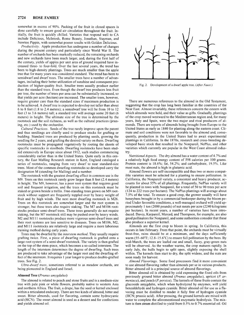
2724 ROSE FAMILY
somewhat in excess of 90%. Packing of the fruit in closed spaces is done carefully to ensure good air circulation throughout the fruit. Initially, the fruit is quickly chilled. Varieties that respond well to CA include Delicious, Mcintosh, Rome Beauty, Jonathan, Stayman, and Newton Pippin, with somewhat poorer results with Golden Delicious.
Productivity. Apple production has undergone a number of changes during the present century and particularly since World War II. The number of orchards has been markedly reduced, the remaining orchards and new orchards have been much larger, and, during the first half of the century, yields of apples per unit area of ground required have increased three- to four-fold. Over the last several years, the trend has been to high-density plantings. Trees are much smaller than the apple tree that for many years was considered standard. The trend has been to semi dwarf and dwarf trees. The smaller trees have a number of advantages, including their better utilization of sunshine and consequent production of higher-quality fruit. Smaller trees usually produce earlier than the standard trees. Even though the dwarf tree produces less fruit per tree, the number of trees per area can be substantially increased, so that yields per acre (hectare) are increased. The smaller trees, however, require greater care than the standard sizes if maximum production is to be achieved. A dwarf tree is expected to develop not taller than about 6 to 8 feet (1.8 to 2.4 meters); a semidwarftree will be from 10 to 12 feet (3 to 3.6 meters) tall; a standard tree will average some 20 feet (6 meters) in height. The ultimate size of the tree is determined by the rootstock and the soil richness, as well as the cultural practices (pruning, etc.) used by the orchardist.
Cultural Practices. Seeds of the tree rarely improve upon the parent and thus seedlings are chiefly used to produce stocks for grafting or budding. Standard trees are produced by planting seeds, growing the seedling for 2 years, and grafting the desired variety on them. Dwarfing rootstocks must be propagated vegetatively by rooting the shoots of specific rootstocks in stoolbeds. Dwarfing rootstocks have been studied extensively in Europe since about 1912, such studies commencing considerably earlier than in the United States. Quite early in this century, the East Mailing Research station in Kent, England cataloged a series of rootstocks, ranging from very dwarf to near standard-size trees. Most of the common dwarfing rootstocks so developed carry the designation M (standing for Mailing) and a number.
The rootstock with the greatest dwarfing effect in common use is the M9. Trees on this rootstock rarely grow larger than 8 feet (2.4 meters) in height. The M9, however, has a poor root system that requires good soil and frequent irrigation, and the trees on this rootstock must be staked or grown beside a trellis. Free-standing trees grown on M9 rootstock without support are frequently toppled over by heavy weight of fruit and by high winds. The next most dwarfing rootstock is M26. Trees on this rootstock are somewhat larger and the root system is stronger, but these trees also require staking. The M7 and Ml06 rootstocks produce semi-dwarf trees. These trees generally do not require staking, but the M7 rootstock still may be pushed over by heavy winds. M2 and Mill rootstocks produce more vigorous semi-dwarf trees and their root systems are less sensitive to diseases. Trees on Ml 06, M2, and MIll rootstocks are relatively large and require a more laborious training method during early years.
Trees may be dwarfed by the interstem method. They usually require grafting twice. First, a piece of dwarfing rootstock is grafted onto a large root system of a semi -dwarf rootstock. The variety is then grafted on the top of the stem-piece, which becomes a so-called interstem. The length of the interstem determines the degree of dwarfing. Such trees are produced to take advantage of the larger root and the dwarfing effect of the interstem. It requires I year longer to produce double-grafted trees. See Fig. 2.
Ultra-dwarf trees, sometimes referred to as meadow orchards, are being pioneered in England and Israel.
Almond Tree (Prunus amygdalus)
The almond is related to peach and stone fruits and is a medium-size tree with pale pink or white flowers, probably native to western Asia and northern Africa. The fruit, a drupe, has the seed or kernel enclosed within a reticulated endocarp. There are two kinds of almond, bitter and sweet. Bitter almonds, used for flavoring, contain some hydrocyanic acid (HCN). The sweet almond is used as a dessert and for confections and yields almond oil.
Fig. 2. Development of a dwarf apple tree. (After Faust.)
There are numerous references to the almond in the Old Testament, suggesting that the crop has long been familiar in the countries of the Near East. Almost invariably, these references concern the esteem with which almonds were held, and their value as gifts. Gradually, plantings of the crop moved westward to the Mediterranean region and, for many years, Italy and Spain, were the two major and rival producers of almonds. There are reports of almonds being brought from Europe to the United States as early as 1840 for planting along the eastern coast. Climate and soil conditions were not favorable to the almond and, consequently, production in the United States had to await experimental plantings in California. In the 1870s, research and cross-breeding developed basic stock that resulted in the Nonpareil, NePlus, and other varieties which currently are popular in the West Coast almond industry.
Nutritional Aspects. The dry almond has a water content of 4. 7% and a relatively high food energy content of 598 calories per I 00 grams. Protein content is 18.6%; fat, 54.2%; and carbohydrate, 19.5%. Like most nuts, the almond is high in glutamic acid.
Almond flowers are self-incompatible and thus two or more compatible varieties must be selected for a planting to ensure pollination. In California, the Nonpareil variety, a consistent and heavy producer, accounts for about 55% of all plantings. Frequently, NePlus variety will be planted in rows with Nonpareil, for a total of 50 to 90 trees per acre (124 to 222 trees per hectare). The NeP!us plantings will average about 7.5% of the total. To ensure a good crop, the grower usually will have honeybees brought in by a commercial beekeeper during the bloom period Under favorable conditions, a well-managed orchard will yield approximately 1 ton (2000 pounds) of nut meats per acre (2240 kilograms per hectare). In recent years, a number of varieties have been introduced. Davey, Karpareil, Merced, and Thompson, for example, are also good pollinators for Nonpareil, and some authorities consider that these also produce a superior kernel.
Almonds are the first crop to bloom in spring. In California, this occurs in late February. From that point, the orchards must be virtually frost-free, rains should be at a minimum, and the days sufficiently warm (55-60°F; 12.8-15.6°C) to ensure full pollination by the bees. By mid-March, the trees are leafed out and small, fuzzy, gray-green nuts will be observed. As the weather warms, the crop matures rapidly. In early July, the hulls begin to split open, slightly exposing the shell within. The kernels then start to dry, the split widens, and the nuts are soon ready for harvest.
Almond Flavorings. Some food processors find it more convenient to use almond flavoring rather than almonds per se in various products. Bitter almond oil is a principal source of almond flavorings.
Bitter almond oil is obtained by cold expressing the fixed oils from previously ground bitter almond (Prunus amygdalus), apricot (P armeniaca), and peach (P persica). The kernels of these fruits contain the glucoside amygdalin, which when hydrolyzed by enzymes, will yield benzaldehyde and hydrogen cyanide. Bitter almond oil for use as a flavoring must be distilled to render it fully free of hydrogen cyanide (HCN; prussic acid). After pressing, the ground kernels are mixed with water to complete the aforementioned enzymatic hydrolysis. The mixture is then steam distilled to yield from 0.5% to 0.7% essential oil. Oil
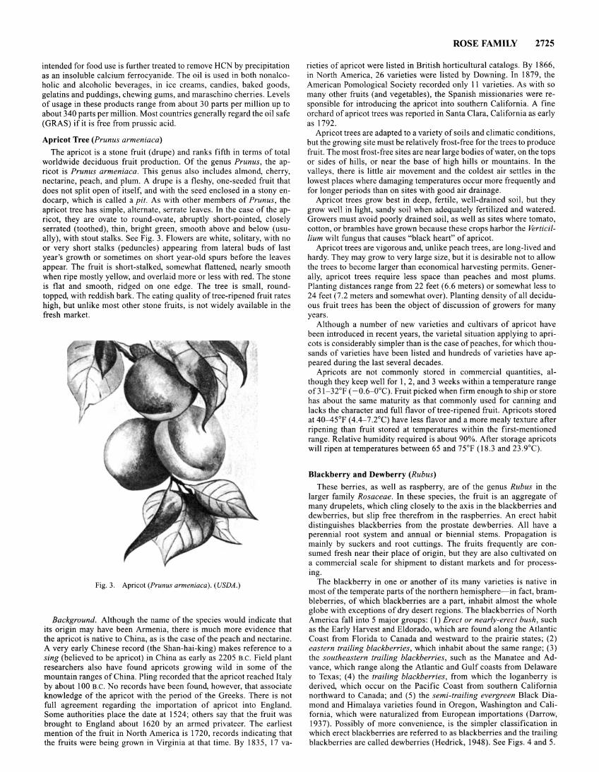
intended for food use is further treated to remove HCN by precipitation as an insoluble calcium ferrocyanide. The oil is used in both nonalcoholic and alcoholic beverages, in ice creams, candies, baked goods, gelatins and puddings, chewing gums, and maraschino cherries. Levels of usage in these products range from about 30 parts per million up to about 340 parts per million. Most countries generally regard the oil safe (GRAS) if it is free from prussic acid.
Apricot Tree (Prunus armeniaca)
The apricot is a stone fruit (drupe) and ranks fifth in terms of total worldwide deciduous fruit production. Of the genus Prunus, the apricot is Prunus armeniaca. This genus also includes almond, cherry, nectarine, peach, and plum. A drupe is a fleshy, one-seeded fruit that does not split open of itself, and with the seed enclosed in a stony endocarp, which is called a pit. As with other members of Prunus, the apricot tree has simple, alternate, serrate leaves. In the case of the apricot, they are ovate to round-ovate, abruptly short-pointed, closely serrated (toothed), thin, bright green, smooth above and below (usually), with stout stalks. See Fig. 3. Flowers are white, solitary, with no or very short stalks (peduncles) appearing from lateral buds of last year's growth or sometimes on short year-old spurs before the leaves appear. The fruit is short-stalked, somewhat flattened, nearly smooth when ripe mostly yellow, and overlaid more or less with red. The stone is flat and smooth, ridged on one edge. The tree is small, roundtopped, with reddish bark. The eating quality of tree-ripened fruit rates high, but unlike most other stone fruits, is not widely available in the fresh market.
Fig. 3. Apricot (Prunus armeniaca). (USDA.)
Background. Although the name of the species would indicate that its origin may have been Armenia, there is much more evidence that the apricot is native to China, as is the case of the peach and nectarine. A very early Chinese record (the Shan-hai-king) makes reference to a sing (believed to be apricot) in China as early as 2205 B.C. Field plant researchers also have found apricots growing wild in some of the mountain ranges of China. Piing recorded that the apricot reached Italy by about 100 B.C. No records have been found, however, that associate knowledge of the apricot with the period of the Greeks. There is not full agreement regarding the importation of apricot into England. Some authorities place the date at 1524; others say that the fruit was brought to England about 1620 by an armed privateer. The earliest mention of the fruit in North America is 1720, records indicating that the fruits were being grown in Virginia at that time. By 1835, 17 va-
ROSE FAMILY 2725
rieties of apricot were listed in British horticultural catalogs. By 1866, in North America, 26 varieties were listed by Downing. In 1879, the American Pomological Society recorded only 11 varieties. As with so many other fruits (and vegetables), the Spanish missionaries were responsible for introducing the apricot into southern California. A fine orchard of apricot trees was reported in Santa Clara, California as early as 1792.
Apricot trees are adapted to a variety of soils and climatic conditions, but the growing site must be relatively frost-free for the trees to produce fruit. The most frost-free sites are near large bodies of water, on the tops or sides of hills, or near the base of high hills or mountains. In the valleys, there is little air movement and the coldest air settles in the lowest places where damaging temperatures occur more frequently and for longer periods than on sites with good air drainage.
Apricot trees grow best in deep, fertile, well-drained soil, but they grow well in light, sandy soil when adequately fertilized and watered. Growers must avoid poorly drained soil, as well as sites where tomato, cotton, or brambles have grown because these crops harbor the Verticilhum wilt fungus that causes "black heart" of apricot.
Apricot trees are vigorous and, unlike peach trees, are long-lived and hardy. They may grow to very large size, but it is desirable not to allow the trees to become larger than economical harvesting permits. Generally, apricot trees require less space than peaches and most plums. Planting distances range from 22 feet (6.6 meters) or somewhat less to 24 feet (7 .2 meters and somewhat over). Planting density of all deciduous fruit trees has been the object of discussion of growers for many years.
Although a number of new varieties and cultivars of apricot have been introduced in recent years, the varietal situation applying to apricots is considerably simpler than is the case of peaches, for which thousands of varieties have been listed and hundreds of varieties have appeared during the last several decades.
Apricots are not commonly stored in commercial quantities, although they keep well for 1, 2, and 3 weeks within a temperature range of31-32°F ( -0.6-0°C). Fruit picked when firm enough to ship or store has about the same maturity as that commonly used for canning and lacks the character and full flavor of tree-ripened fruit. Apricots stored at 40-45°F ( 4.4-7 .2°C) have less flavor and a more mealy texture after ripening than fruit stored at temperatures within the first-mentioned range. Relative humidity required is about 90%. After storage apricots will ripen at temperatures between 65 and 75°F ( 18.3 and 23.9°C).
Blackberry and Dewberry (Rubus)
These berries, as well as raspberry, are of the genus Rubus in the larger family Rosaceae. In these species, the fruit is an aggregate of many drupelets, which cling closely to the axis in the blackberries and dewberries, but slip free therefrom in the raspberries. An erect habit distinguishes blackberries from the prostate dewberries. All have a perennial root system and annual or biennial stems. Propagation is mainly by suckers and root cuttings. The fruits frequently are consumed fresh near their place of origin, but they are also cultivated on a commercial scale for shipment to distant markets and for processing.
The blackberry in one or another of its many varieties is native in most of the temperate parts of the northern hemisphere- in fact, brambleberries, of which blackberries are a part, inhabit almost the whole globe with exceptions of dry desert regions. The blackberries of North America fall into 5 major groups: (1) Erect or nearly-erect bush, such as the Early Harvest and Eldorado, which are found along the Atlantic Coast from Florida to Canada and westward to the prairie states; (2) eastern trailing blackberries, which inhabit about the same range; (3) the southeastern trailing blackberries, such as the Manatee and Advance, which range along the Atlantic and Gulf coasts from Delaware to Texas; (4) the trailing blackberries, from which the loganberry is derived, which occur on the Pacific Coast from southern California northward to Canada; and (5) the semi-trailing evergreen Black Diamond and Himalaya varieties found in Oregon, Washington and California, which were naturalized from European importations (Darrow, 1937). Possibly of more convenience, is the simpler classification in which erect blackberries are referred to as blackberries and the trailing blackberries are called dewberries (Hedrick, 1948). See Figs. 4 and 5.
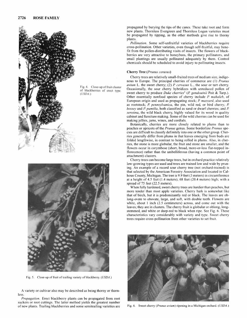
2726 ROSE FAMILY
ig. 4. I e-up of fruit clu ter of blackberrie of erect type. (U DA.)
Fig. 5. Close-up of fruit of trailing variety of blackberry. (USDA .)
A variety or cultivar also may be described as being thorny or thornless.
Propagation. Erect blackberry plants can be propagated from root suckers or root cuttings. The latter method yields the greatest number of new plants. Trailing blackberries and some semitrailing varieties are
propagated by burying the tips of the canes. These take root and form new plants. Thornless Evergreen and Thornless Logan varieties must be propagated by tipping, as the other methods give rise to thorny plants.
Pollination. Some self-unfruitful varieties of blackberries require cross-pollination. Other varieties, even though self-fruitful, may benefit from the pollen-distributing visits of insects. The flowers of blackberries are very attractive to honeybees, the primary pollinators, and small plantings are usually pollinated adequately by them. Control chemicals should be scheduled to avoid injury to pollinating insects.
Cherry Tree (Prunus cerasus)
Cherry trees are relatively small-fruited trees of medium size, indigenous to Europe. The principal cherries of commerce are (I) Prunus avium L. the sweet cherry; (2) P. cervasus L., the sour or tart cherry. Occasionally, the sour cherry hybridizes with unreduced pollen of sweet cherry to produce Duke cherries1 (P. gondouinii Poit & Turp.). Other essentially nonfood species of cherry include P. mahaleb, of European origin and used as propagating stock; P. mazzard, also used as rootstock; P. pennsylvanica, the pin, wild red, or bird cherry; P. bessey and P. pumilla, both classified as sand or dwarf cherries; and P. serotina, the wild black cherry, highly valued for its wood in quality cabinet and furniture making. Some of the wild cherries can be used for making jellies, jams, wines, and cordials.
Botanically, cherries are more closely related to plums than to peaches or apricots of the Prunus genus. Some borderline Prunus species are difficult to classify definitely into one or the other group. Cherries generally differ from plums in that leaves emerging from buds are folded lengthwise, in contrast to being rolled in plums. Also. in cherries, the stone is more globular, the fruit and stone are smaller, and the flowers occur in corymbose (short, broad, more-or-less flat-topped inflorecence) rather than the umbelliferous (having a common point of attachment) clusters.
Cherry trees can become large trees, but in orchard practice relatively low-growing types are used and trees are trained low and wide by pruning. An example of a record sour cherry tree (not orchard-trained) is that selected by the American Forestry Association and located in Calhoun County, Michigan. The tree is 9.9 feet (3 meters) in circumference at a height of 4.5 feet (1.4 meters); 68 feet (20.4 meters) high; with a spread of 75 feet (22.5 meters).
When fully hardened, sweet cherry trees are hardier than peaches, but more tender than most apple varieties. Cherry bark is somewhat like that of birch, but it is predominantly red or black. The leaves are oblong-ovate to obovate, large, and soft, with double teeth. Flowers are white, about I inch (2.5 centimeters) across, and come out with the leaves; they are in clusters. The cherry fruit is globular or oblong, longstemmed, and white or deep-red to black when ripe. See Fig. 6. These characteristics vary considerably with variety and type. Sweet cherry trees require cross-pollination from other varieties to set fruit.
Fig. 6. Sweet cherry (Prunus avium) ripening in a Michigan orchard. (USDA.)
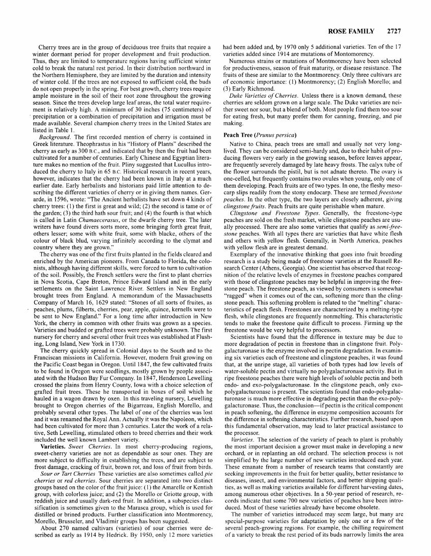
Cherry trees are in the group of deciduous tree fruits that require a winter dormant period for proper development and fruit production. Thus, they are limited to temperature regions having sufficient winter cold to break the natural rest period. In their distribution northward in the Northern Hemisphere, they are limited by the duration and intensity of winter cold. If the trees are not exposed to sufficient cold, the buds do not open properly in the spring. For best growth, cherry trees require ample moisture in the soil of their root zone throughout the growing season. Since the trees develop large leaf areas, the total water requirement is relatively high. A minimum of 30 inches (75 centimeters) of
· precipitation or a combination of precipitation and irrigation must be made available. Several champion cherry trees in the United States are listed in Table I.
Background. The first recorded mention of cherry is contained in Greek literature. Theophrastus in his "History of Plants" described the cherry as early as 300 B.C., and indicated that by then the fruit had been cultivated for a number of centuries. Early Chinese and Egyptian literature makes no mention of the fruit. Pliny suggested that Lucullus introduced the cherry to Italy in 65 B.C. Historical research in recent years, however, indicates that the cherry had been known in Italy at a much earlier date. Early herbalists and historians paid little attention to describing the different varieties of cherry or in giving them names. Gerarde, in 1596, wrote: "The Ancient herbalists have set down 4 kinds of cherry trees: (I) the first is great and wild; (2) the second is tame or of the garden; (3) the third hath sour fruit; and (4) the fourth is that which is called in Latin Chamaecerasus, or the dwarfe cherry tree. The later writers have found divers sorts more, some bringing forth great fruit, others lesser; some with white fruit, some with blacke, others of the colour of black blud, varying infinitely according to the clymat and country where they are grown."
The cherry was one of the first fruits planted in the fields cleared and enriched by the American pioneers. From Canada to Florida, the colonists, although having different skills, were forced to turn to cultivation of the soil. Possibly, the French settlers were the first to plant cherries in Nova Scotia, Cape Breton, Prince Edward Island and in the early settlements on the Saint Lawrence River. Settlers in New England brought trees from England. A memorandum of the Massachusetts Company of March 16, 1629 stated: "Stones of all sorts of fruites, as peaches, plums, filberts, cherries, pear, apple, quince, kernells were to be sent to New England." For a long time after introduction in New York, the cherry in common with other fruits was grown as a species. Varieties and budded or grafted trees were probably unknown. The first nursery for cherry and several other fruit trees was established at Flushing, Long Island, New York in 1730.
The cherry quickly spread in Colonial days to the South and to the Franciscan missions in California. However, modern fruit growing on the Pacific Coast began in Oregon. Until 184 7, the few cultivated fruits to be found in Oregon were seedlings, mostly grown by people associated with the Hudson Bay Fur Company. In 1847, Henderson Lewelling crossed the plains from Henry County, Iowa with a choice selection of grafted fruit trees. These he transported in boxes of soil which he hauled in a wagon drawn by oxen. In this traveling nursery, Lewelling brought to Oregon cherries of the Bigarreau, English Morello, and probably several other types. The label of one of the cherries was lost and it was renamed the Royal Ann. Actually it was the Napoleon, which had been cultivated for more than 3 centuries. Later the work of a relative, Seth Lewelling, stimulated others to breed cherries and their work included the well known Lambert variety.
Varieties. Sweet Cherries. In most cherry-producing regions, sweet-cherry varieties are not as dependable as sour ones. They are more subject to difficulty in establishing the trees, and are subject to frost damage, cracking of fruit, brown rot, and loss of fruit from birds.
Sour or Tart Cherries These varieties are also sometimes called pie cherries or red cherries. Sour cherries are separated into two distinct groups based on the color of the fruit juice: ( 1) the Amarelle or Kentish group, with colorless juice; and (2) the Morello or Griotte group, with reddish juice and usually dark-red fruit. In addition, a subspecies classification is sometimes given to the Marasca group, which is used for distilled or brined products. Further classification into Montmorency, Morello, Brusseler, and Vladimir groups has been suggested.
About 270 named cultivars (varieties) of sour cherries were described as early as 1914 by Hedrick. By 1950, only 12 more varieties
ROSE FAMILY 2727
had been added and, by 1970 only 5 additional varieties. Ten of the 17 varieties added since 1914 are mutations of Montomorency.
Numerous strains or mutations of Montmorency have been selected for productiveness, season of fruit maturity, or disease resistance. The fruits of these are similar to the Montmorency. Only three cultivars are of economic importance: (1) Montmorency; (2) English Morello; and (3) Early Richmond.
Duke Varieties of Cherries. Unless there is a known demand, these cherries are seldom grown on a large scale. The Duke varieties are neither sweet nor sour, but a blend of both. Most people find them too sour for eating fresh, but many prefer them for canning, freezing, and pie making.
Peach Tree (Prunus persica)
Native to China, peach trees are small and usually not very longlived. They can be considered semi-hardy and, due to their habit of producing flowers very early in the growing season, before leaves appear, are frequently severely damaged by late heavy frosts. The calyx tube of the flower surrounds the pistil, but is not adnate thereto. The ovary is one-celled, but frequently contains two ovules when young, only one of them developing. Peach fruits are of two types. In one, the fleshy mesocarp slips readily from the stony endocarp. These are termed freestone peaches. In the other type, the two layers are closely adherent, giving clingstone fruits. Peach fruits are quite perishable when mature.
Clingstone and Freestone Types. Generally, the freestone-type peaches are sold on the fresh market, while clingstone peaches are usually processed. There are also some varieties that qualify as semi-freestone peaches. With all types there are varieties that have white flesh and others with yellow flesh. Generally, in North America, peaches with yellow flesh are in greatest demand.
Exemplary of the innovative thinking that goes into fruit breeding research is a study being made of freestone varieties at the Russell Research Center (Athens, Georgia). One scientist has observed that recognition of the relative levels of enzymes in freestone peaches compared with those of clingstone peaches may be helpful in improving the freestone peach. The freestone peach, as viewed by consumers is somewhat "ragged" when it comes out of the can, softening more than the clingstone peach. This softening problem is related to the "melting" characteristics of peach flesh. Freestones are characterized by a melting-type flesh, while clingstones are frequently nonmelting. This characteristic tends to make the freestone quite difficult to process. Firming up the freestone would be very helpful to processors. ·
Scientists have found that the difference in texture may be due to more degradation of pectin in freestone than in clingstone fruit. Polygalacturonase is the enzyme involved in pectin degradation. In examining six varieties each of freestone and clingstone peaches, it was found that, at the unripe stage, all varieties of both types had low levels of water-soluble pectin and virtually no polygalacturonase activity. But in ripe freestone peaches there were high levels of soluble pectin and both endo- and exo-polygalacturonase. In the clingstone peach, only exopolygalacturonase is present. The scientists found that endo-polygalacturonase is much more effective in degrading pectin than the exo-polygalacturonase. Thus, the conclusion-if pectin is the critical component in peach softening, the difference in enzyme composition accounts for the difference in softening characteristics. Further research, based upon this fundamental observation, may lead to later practical assistance to the processor.
Varieties. The selection of the variety of peach to plant is probably the most important decision a grower must make in developing a new orchard, or in replanting an old orchard. The selection process is not simplified by the large number of new varieties introduced each year. These emanate from a number of research teams that constantly are seeking improvements in the fruit for better quality, better resistance to diseases, insect, and environmental factors, and better shipping qualities, as well as making varieties available for different harvesting dates, among numerous other objectives. In a 50-year period of research, records indicate that some 700 new varieties of peaches have been introduced. Most of these varieties already have become obsolete.
The number of varieties introduced may seem large, but many are special-purpose varieties for adaptation by only one or a few of the several peach-growing regions. For example, the chilling requirement of a variety to break the rest period of its buds narrowly limits the area
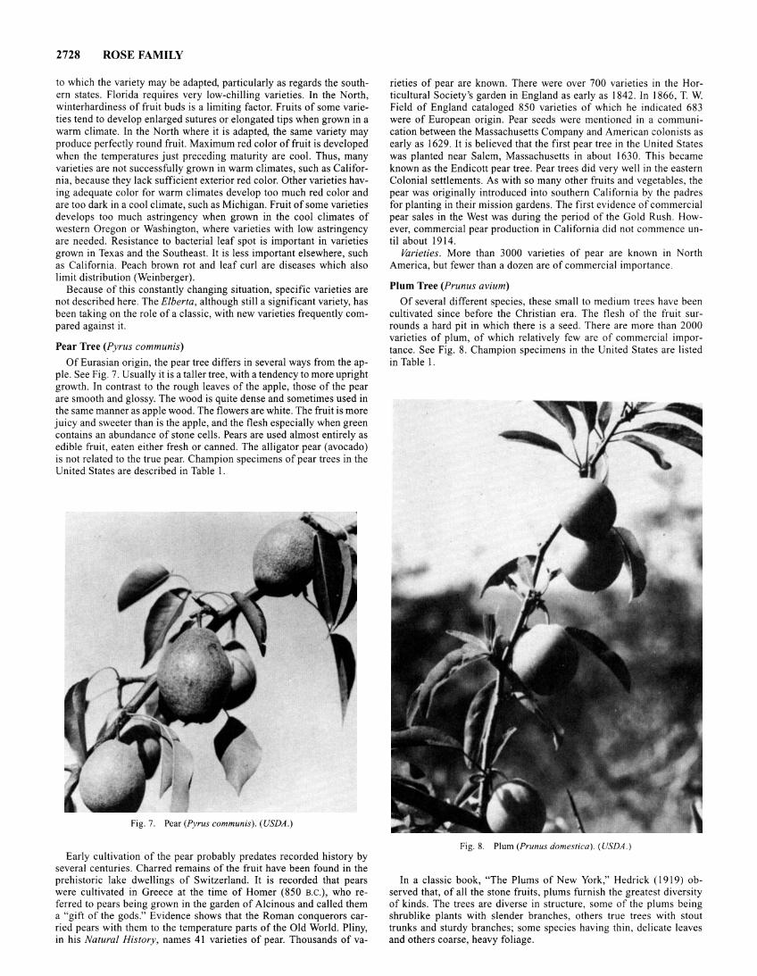
2728 ROSE FAMILY
to which the variety may be adapted, particularly as regards the southern states. Florida requires very low-chilling varieties. In the North, winterhardiness of fruit buds is a limiting factor. Fruits of some varieties tend to develop enlarged sutures or elongated tips when grown in a warm climate. In the North where it is adapted, the same variety may produce perfectly round fruit. Maximum red color offruit is developed when the temperatures just preceding maturity are cool. Thus, many varieties are not successfully grown in warm climates, such as California, because they lack sufficient exterior red color. Other varieties having adequate color for warm climates develop too much red color and are too dark in a cool climate, such as Michigan. Fruit of some varieties develops too much astringency when grown in the cool climates of western Oregon or Washington, where varieties with low astringency are needed. Resistance to bacterial leaf spot is important in varieties grown in Texas and the Southeast. It is less important elsewhere, such as California. Peach brown rot and leaf curl are diseases which also limit distribution (Weinberger).
Because of this constantly changing situation, specific varieties are not described here. The Elberta, although still a significant variety, has been taking on the role of a classic, with new varieties frequently compared against it.
Pear Tree (Pyrus communis)
Of Eurasian origin, the pear tree differs in several ways from the apple. See Fig. 7. Usually it is a taller tree, with a tendency to more upright growth. In contrast to the rough leaves of the apple, those of the pear are smooth and glossy. The wood is quite dense and sometimes used in the same manner as apple wood. The flowers are white. The fruit is more juicy and sweeter than is the apple, and the flesh especially when green contains an abundance of stone cells. Pears are used almost entirely as edible fruit, eaten either fresh or canned. The alligator pear (avocado) is not related to the true pear. Champion specimens of pear trees in the United States are described in Table I.
Fig. 7. Pear (Pyrus communis). (USDA.)
Early cultivation of the pear probably predates recorded history by several centuries. Charred remains of the fruit have been found in the prehistoric lake dwellings of Switzerland. It is recorded that pears were cultivated in Greece at the time of Homer (850 B.C.), who referred to pears being grown in the garden of Alcinous and called them a "gift of the gods." Evidence shows that the Roman conquerors carried pears with them to the temperature parts of the Old World. Pliny, in his Natural History, names 41 varieties of pear. Thousands of va-
rieties of pear are known. There were over 700 varieties in the Horticultural Society's garden in England as early as 1842. In 1866, T. W. Field of England cataloged 850 varieties of which he indicated 683 were of European origin. Pear seeds were mentioned in a communication between the Massachusetts Company and American colonists as early as 1629. It is believed that the first pear tree in the United States was planted near Salem, Massachusetts in about 1630. This became known as the Endicott pear tree. Pear trees did very well in the eastern Colonial settlements. As with so many other fruits and vegetables, the pear was originally introduced into southern California by the padres for planting in their mission gardens. The first evidence of commercial pear sales in the West was during the period of the Gold Rush. However, commercial pear production in California did not commence until about 1914.
Varieties. More than 3000 varieties of pear are known in North America, but fewer than a dozen are of commercial importance.
Plum Tree (Prunus avium)
Of several different species, these small to medium trees have been cultivated since before the Christian era. The flesh of the fruit surrounds a hard pit in which there is a seed. There are more than 2000 varieties of plum, of which relatively few are of commercial importance. See Fig. 8. Champion specimens in the United States are listed in Table I.
Fig. 8. Plum (Prunus domestica ). (USDA .)
In a classic book, "The Plums of New York," Hedrick ( 1919) observed that, of all the stone fruits, plums furnish the greatest diversity of kinds. The trees are diverse in structure, some of the plums being shrublike plants with slender branches, others true trees with stout trunks and sturdy branches; some species having thin, delicate leaves and others coarse, heavy foliage.
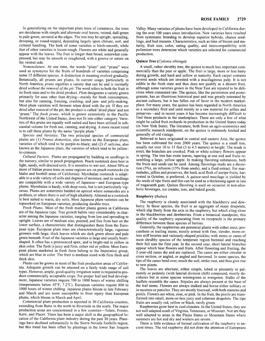
In generalizing on the important plum trees of commerce, the trees are deciduous with simple and alternate oval leaves, veined, dull-green to pale-green, serrated at the edges. The tree may be upright, spreading, drooping, or round-topped, depending largely upon climate, soil, and cultural handling. The bark of some varieties is birch-smooth, while that of other varieties is locust-rough. Flowers are white and generally appear with the leaves. The fruit is longer than broad, somewhat compressed, but may be smooth or roughened, with a groove or suture on the ventral side.
Nomenclature. At one time, the words "plum" and "prune" were used as synonyms for the fruits of hundreds of varieties comprising some 15 different species. A distinction in meaning evolved gradually. Botanically, all prunes are plums. In current usage, particularly in North America, prune signifies a variety that can be and is normally dried without the removal of the pit. The word refers to both the fruit in its fresh state and to the dried product. Plum designates a variety grown primarily for uses other than drying-mainly for fresh consumption, but also for canning, freezing, crushing, and jam- and jelly-making. Most plum varieties will ferment when dried with the pit. If they are dried after removal of the pit, the product is called 'dried plum' and not 'prune.' The fresh prune, which is grown extensively in the Pacific Northwest of the United States, does not fit into either category. Varieties of this prune are equally well suited and have been utilized in substantial volume for fresh use, canning, and drying. A more recent trend is to call these plums by the name "purple plum."
Species and Varieties. The two principal species of commercial plums are (I) Prunus domestica, also known as the European plum, varieties of which tend to be purple-to-black; and (2) P salicina, also known as the Japanese plum, the varieties of which tend to be yellowto-crimson.
Cultural Factors. Plums are propagated by budding on seedlings in the nursery, similar to peach propagation. Peach rootstock does best in light, sandy, well-drained soils. It is sensitive to wet soil. About 50% or more of Italian prune trees in some regions are on peach rootstocks (in Idaho and foothill areas of California). Myrobalan rootstock is adaptable to a wide variety of soils and degrees of moisture, and its seedlings are compatible with a wide variety of Japanese-and European-type plums. Myrobalan is hardy, with deep roots, but is not particularly vigorous. Plums are sometimes budded on apricot where nematodes are a problem, or where there is soil of high alkalinity. Almond as a rootstock is best suited to warm, dry soils. Most Japanese plum varieties can be topworked on European varieties, producing durable trees.
Fresh Plums. Most of the fresh market plums grown in California are of the Japanese type. Tree growth habits vary considerably in character among the Japanese varieties, ranging from low and spreading to upright. Leaves are of medium size, pointed, and free from hair on the lower surface, a characteristic that distinguishes them from the European type. European plum trees are characteristically large, vigorous growers with large, thick leaves which are dark green above and pale green beneath. Fruit of the Japanese varieties is large and usually heartshaped. It often has a pronounced apex, and is bright-red or yellow in skin color. The flesh is juicy and firm, either red or yellow. Most European plums marketed in fresh form belong to the Imperatice group, which are blue in color. The fruit is medium sized with firm flesh and thick skin.
Plums can be grown in most of the fruit production areas of California. Adequate growth can be attained on a fairly wide range of soil types. However, ample, good-quality irrigation water is required to produce commercially acceptable crops. For proper leaf and bud development, Japanese varieties require 700 to 1000 hours of winter chilling (temperatures below 45°F; 7.2°C). European varieties require 800 to 1000 hours of winter chilling. Japanese plums bloom in late February and March and are more susceptible to frost injury than European plums, which bloom in March and April.
Commercial plum production is reported in 30 California counties, extending from Butte in the north to Riverside in the south. The major production areas are concentrated in a few counties-Tulare, Fresno, Kern, and Placer. There has been a major shift in the geographical location of the California plum industry during the past 30 years. Plantings have declined substantially in the Sierra Nevada foothills region, but this trend has been offset by plantings in the lower San Joaquin
ROSE FAMILY 2729
Valley. Many varieties of plums have been developed in California during the over 100 years since introduction. New varieties have resulted from systematic breeding to develop superior hybrids, chance seedlings, and bud mutants. Characteristics, such as time of bloom and maturity, fruit size, color, eating quality, and intercompatibility with pollenizer trees determine which varieties are selected for commercial production.
Quince Tree (Cydonia oblonga)
A small, rather shrubby tree, the quince is much less important commercially than the pear or apple. The fruit is large, more or less hairy during growth, and hard and yellow at maturity. Each carpel contains several seeds which are invested with a mucilaginous pulp. It is not edible in the fresh state and thus does not qualify as a dessert fruit, although some varieties grown in the Near East are reputed to be delicious when consumed raw. The quince, like the persimmon and pomegranate, has an illustrious historical past and was greatly esteemed by ancient cultures, but it has fallen out of favor in the modern marketplace. For many years, the quince has been regarded in North America as a secondary fruit and used mainly as a raw material for jellies and preserves-and in recent years it has become increasingly difficult to find these products in the marketplace. There are only a few of what might be called fruit orchards in production in the United States today (in New York State). The literature, both from an agro-economics and scientific research standpoint, on the quince is extremely limited and generally of old vintage.
Believed to have originated in central and eastern Asia, the quince has been cultivated for over 2000 years. The quince is a small tree, usually not over 10 to 15 feet (3 to 4.5 meters) in height. The trunk is erect; the branches are crooked. Pink or white solitary flowers appear in spring. The tree has ovate leaves, tapering at one end and fruits resembling a large, yellow apple. In making flavoring substances, both the fruits and seeds can be used. Among flavorings made are a decoction (5%), an infusion (15% from seeds), and a fluid extract. For marmalades, jellies and preserves, the hard, acid flesh of unripe fruits, harvested in October, is preferred. A quince-seed mucilage is yielded by the seeds of ripe fruits and this can be used as a thickening agent in lieu of tragacanth gum. Quince flavoring is used on occasion in non-alcoholic beverages, ice creams, ices, and baked goods.
Raspberry (Rubus)
The raspberry is closely associated with the blackberry and dewberry. In these species, the fruit is an aggregate of many drupelets, which slip freely from the axis in the raspberry, but which cling close in the blackberries and dewberries. From a botanical standpoint, this quality of the raspberry separating from its receptacle is the primary difference between these species of berries.
Generally, the raspberries are perennial plants with either erect, procumbent or trailing stems; mostly armed with fine, slender, more-orless stiff bristles and variously-shaped prickles; with stems or canes of most shrubby species of the temperate region biennial and reaching their full size the first year. In the second year, short lateral branches appear which bear flowers and fruits. After flowering and fruiting, the 2-year-old canes die and are replaced. The canes are either circular in cross section, or angled, or angled and furrowed. In some species, the tips of the canes bend over, touch the soil, strike root, and thus give rise to new plants.
The leaves are alternate, either simple, lobed or pinnately or palmately or pedately (with lateria1 division cleft) compound, mostly deciduous but in some species wintergreen or evergreen. Stalks of the leaflets resemble the canes. Stipules are always present at the base of the leaf stems. Flowers are always stalked and borne either solitary or in racemes or panicles. They are mostly bisexual, with both stamens and pistils. Flowers are white, rose, or pink. In the fruit, the pistils are transformed into small, more-or-less juicy and coherent drupelets. The ripe fruits are usually red, yellow or black, rarely green.
Raspberries grow best in cool climates. In the United States, they are not well adapted south of Virginia, Tennessee, or Missouri. Nor are they well adapted to areas in the Plains States or Mountain States where summers are hot and dry and winters are severe.
There is little evidence of formal cultivation of the raspberry in ancient times. The red raspberry did not draw the attention of Europeans
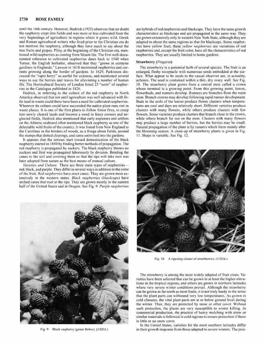
2730 ROSE FAMILY
until the 16th century. However, Hedrick ( 1925) observes that no doubt the raspberry crept into fields and was more or less cultivated from the very beginnings of agriculture in regions where it grows wild. Greek and Roman agricultural writers who lived prior to the Christian era do not mention the raspberry, although they have much to say about the tree fruits and grapes. Pliny, at the beginning of the Christian era, mentioned wild raspberries as coming from Mount Ida. The first well-documented reference to cultivated raspberries dates back to 1548 when Turner, the English herbalist, observed that they "growe in certayne gardines in Englande." Lawson in 1618 mentioned raspberries and currants growing along the border of gardens. In 1629, Parkinson discussed the "rapis berry" as useful for sickness, and mentioned several ways to use the berries and leaves for alleviating a number of human ills. The Horticultural Society of London listed 23 "sorts" of raspberries in the Catalogue published in 1826.
Hedrick, in referring to the culture of the red raspberry in North America observed that not until agriculture was well advanced with little land in waste could there have been a need for cultivated raspberries. Wherever its culture could have succeeded the native plant runs riot in waste places. It is one of the first .plants to follow forest fires, to creep into newly cleared lands and become a weed in fence corners and neglected fields. Hedrick also mentioned that early explorers and settlers on the Atlantic seaboard often mentioned black raspberry as one of the delectable wild fruits of the country. It was found from New England to the Carolinas in the borders of woods, as a fringe about fields, around the stumps that dotted clearings, and came uninvited into the gardens.
It appears that the serious start toward domestication of the black raspberry started in 1850 by finding better methods of propagation. The red raspberry is propagated by suckers. The black raspberry throws no suckers and first was propagated laboriously by division. Bending the canes to the soil and covering them so that the tips will take root was later adopted from nature as the best means of manual culture.
Varieties and Culture. There are three main types of raspberriesred, black, and purple. They differ in several ways in addition to the color of the fruit. Red raspberries have erect canes. They are grown most extensively in the western states. Black raspberries (blackcaps) have arched canes that root at the tips. They are grown mostly in the eastern half of the United States and in Oregon. See Fig. 9. Purple raspberries
Fig. 9. Black raspberry (genus Rubus). (USDA.)
are hybrids of red raspberries and blackcaps. They have the same growth characteristics as blackcaps and are propagated in the same way. They are grown extensively only in western New York State, although they are adapted to about the same regions as that for blackcaps. Some raspberries have yellow fruit; these yellow raspberries are variations of red raspberries and, except for fruit color, have all the characteristics of red raspberries. They are usually limited to home gardens.
Strawberry (Fragaria)
The strawberry is a perennial herb of several species. The fruit is an enlarged, fleshy receptacle with numerous seeds embedded at the surface. What appear to be seeds to the casual observer are, in actuality, achenes. The seed is contained within a thin, dry ovary wall. See Fig. 10. The strawberry plant grows from a central stem called a crown whose terminal is a growing point. From this growing point, leaves, flowerbuds, and runners develop. Runners are branches from the main stem. Branch crowns may develop following rapid runner development. Buds in the axils of the leaves produce flower clusters when temperatures are cool and days are relatively short. Different varieties produce clusters with many flowers, while others produce clusters with few flowers. Some varieties produce clusters that branch close to the crown, while others branch far out on the stem. Clusters with many flowers may produce a large number of berries, but the berries may be small. Natural propagation of the plant is by runners which form mainly after the blooming season. A close-up of strawberry plants is given in Fig. II. Shape is variable. See Fig. 12.
Fig. I 0. A ripening cluster of strawberries. (USDA.)
The strawberry is among the most widely adapted of fruit crops. Varieties have been selected that can be grown in at least the higher elevations in the tropical regions, and others are grown in northern latitudes where very severe winter conditions prevail. Although the strawberry can be grown as far north as most fruits, it is not truly hardy in the sense that the plant parts can withstand very low temperatures. As grown in cold climates, the vital plant parts are at or below ground level during the winter. Thus, they are protected by snow or other cover. Without such protection, the plants are very susceptible to winter killing. In commercial production, the practice of heavy mulching with straw or similar materials is followed in cold regions to ensure protection ifthere is little or no snow cover.
In the United States, varieties for the most southern latitudes differ in their growth response from those adapted to severe winters. The prin-
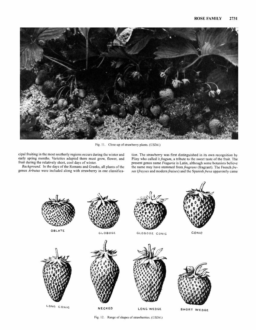
ROSE FAMILY 2731
Fig. II. Close-up of strawberry plants. (USDA .)
cipal fruiting in the most southerly regions occurs during the winter and early spring months. Varieties adapted there must grow, flower, and fruit during the relatively short, cool days of winter.
Background. In the days of the Romans and Greeks, all plants of the genus Arbutus were included along with strawberry in one classifica-
OB L A TE: GLOBOSE.
LONG C ONIC N EC KED
tion. The strawberry was first distinguished in its own recognition by Pliny who called itfragum, a tribute to the sweet taste of the fruit. The present genus name Fragaria is Latin, although some botanists believe the name may have stemmed fromfragrans (fragrant). The Frenchfresas (jrayses and modern/raises) and the Spanishfresa apparently came
GLOBOSE. CONIC CONIC
LONG Wf-OGE. SHORT W E DGE
Fig. 12. Range of shapes of strawberries. (USDA.)
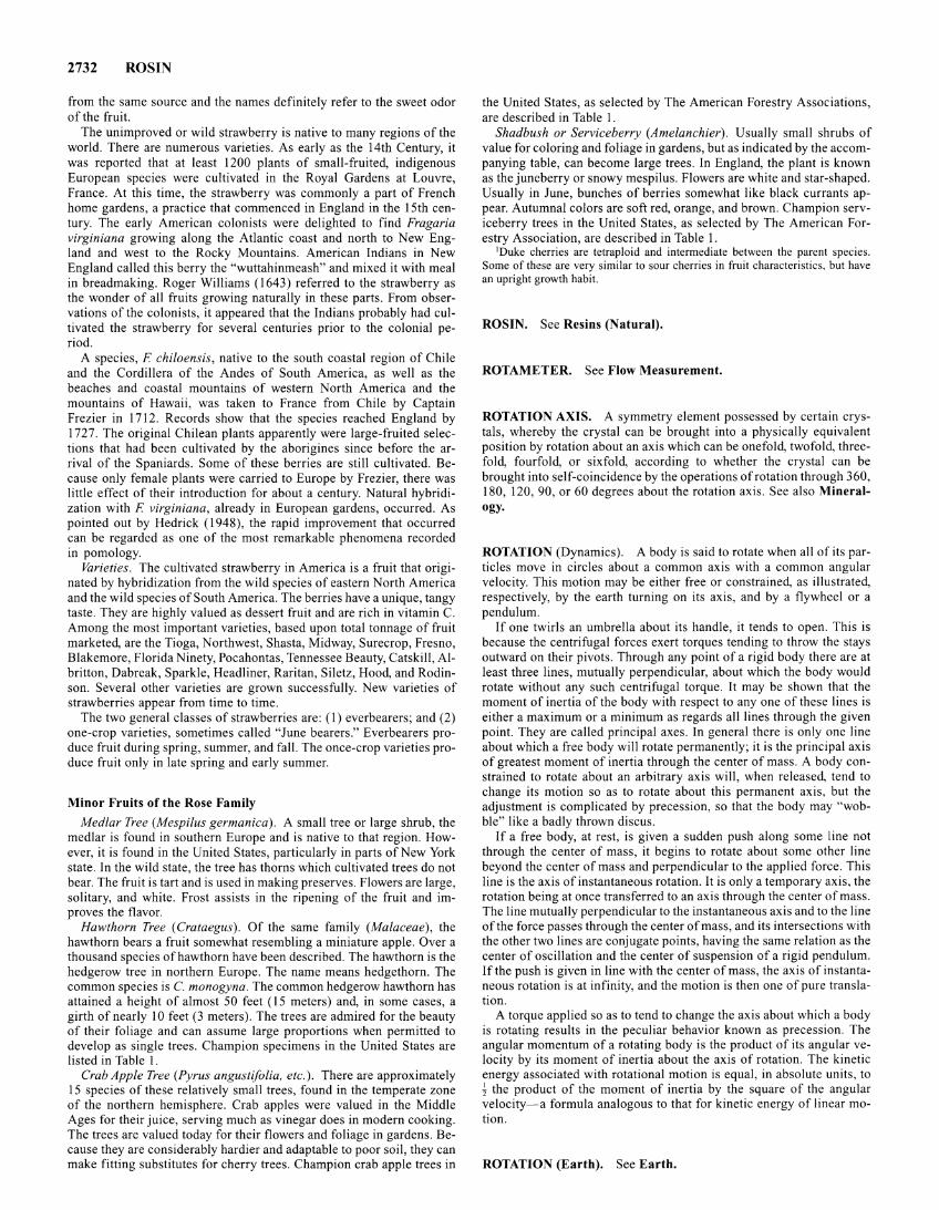
2732 ROSIN
from the same source and the names definitely refer to the sweet odor of the fruit.
The unimproved or wild strawberry is native to many regions of the world. There are numerous varieties. As early as the 14th Century, it was reported that at least 1200 plants of small-fruited, indigenous European species were cultivated in the Royal Gardens at Louvre, France. At this time, the strawberry was commonly a part of French home gardens, a practice that commenced in England in the 15th century. The early American colonists were delighted to find Fragaria virginiana growing along the Atlantic coast and north to New England and west to the Rocky Mountains. American Indians in New England called this berry the "wuttahinmeash" and mixed it with meal in breadmaking. Roger Williams (1643) referred to the strawberry as the wonder of all fruits growing naturally in these parts. From observations of the colonists, it appeared that the Indians probably had cultivated the strawberry for several centuries prior to the colonial period.
A species, F chiloensis, native to the south coastal region of Chile and the Cordillera of the Andes of South America, as well as the beaches and coastal mountains of western North America and the mountains of Hawaii, was taken to France from Chile by Captain Frezier in 1712. Records show that the species reached England by 1727. The original Chilean plants apparently were large-fruited selections that had been cultivated by the aborigines since before the arrival of the Spaniards. Some of these berries are still cultivated. Because only female plants were carried to Europe by Frezier, there was little effect of their introduction for about a century. Natural hybridization with F virginiana, already in European gardens, occurred. As pointed out by Hedrick (1948), the rapid improvement that occurred can be regarded as one of the most remarkable phenomena recorded in pomology.
Varieties. The cultivated strawberry in America is a fruit that originated by hybridization from the wild species of eastern North America and the wild species of South America. The berries have a unique, tangy taste. They are highly valued as dessert fruit and are rich in vitamin C. Among the most important varieties, based upon total tonnage of fruit marketed, are the Tioga, Northwest, Shasta, Midway, Surecrop, Fresno, Blakemore, Florida Ninety, Pocahontas, Tennessee Beauty, Catskill, Albritton, Dabreak, Sparkle, Headliner, Raritan, Siletz, Hood, and Rodinson. Several other varieties are grown successfully. New varieties of strawberries appear from time to time.
The two general classes of strawberries are: ( 1) everbearers; and (2) one-crop varieties, sometimes called "June bearers." Everbearers produce fruit during spring, summer, and fall. The once-crop varieties produce fruit only in late spring and early summer.
Minor Fruits of the Rose Family
Medlar Tree (Mespilus germanica). A small tree or large shrub, the medlar is found in southern Europe and is native to that region. However, it is found in the United States, particularly in parts of New York state. In the wild state, the tree has thorns which cultivated trees do not bear. The fruit is tart and is used in making preserves. Flowers are large, solitary, and white. Frost assists in the ripening of the fruit and improves the flavor.
Hawthorn Tree (Crataegus). Of the same family (Malaceae), the hawthorn bears a fruit somewhat resembling a miniature apple. Over a thousand species of hawthorn have been described. The hawthorn is the hedgerow tree in northern Europe. The name means hedgethorn. The common species is C. monogyna. The common hedgerow hawthorn has attained a height of almost 50 feet (15 meters) and, in some cases, a girth of nearly 10 feet (3 meters). The trees are admired for the beauty of their foliage and can assume large proportions when permitted to develop as single trees. Champion specimens in the United States are listed in Table 1.
Crab Apple Tree (Pyrus angustifolia, etc.). There are approximately 15 species of these relatively small trees, found in the temperate zone of the northern hemisphere. Crab apples were valued in the Middle Ages for their juice, serving much as vinegar does in modern cooking. The trees are valued today for their flowers and foliage in gardens. Because they are considerably hardier and adaptable to poor soil, they can make fitting substitutes for cherry trees. Champion crab apple trees in
the United States, as selected by The American Forestry Associations, are described in Table I.
Shadbush or Serviceberry (Amelanchier). Usually small shrubs of value for coloring and foliage in gardens, but as indicated by the accompanying table, can become large trees. In England, the plant is known as the june berry or snowy mespilus. Flowers are white and star-shaped. Usually in June, bunches of berries somewhat like black currants appear. Autumnal colors are soft red, orange, and brown. Champion serviceberry trees in the United States, as selected by The American Forestry Association, are described in Table I.
1 Duke cherries are tetraploid and intermediate between the parent species. Some of these are very similar to sour cherries in fruit characteristics, but have an upright growth habit.
ROSIN. See Resins (Natural).
ROTAMETER. See Flow Measurement.
ROTATION AXIS. A symmetry element possessed by certain crystals, whereby the crystal can be brought into a physically equivalent position by rotation about an axis which can be onefold, twofold, threefold, fourfold, or sixfold, according to whether the crystal can be brought into self-coincidence by the operations of rotation through 360, 180, 120, 90, or 60 degrees about the rotation axis. See also Mineralogy.
ROTATION (Dynamics). A body is said to rotate when all of its particles move in circles about a common axis with a common angular velocity. This motion may be either free or constrained, as illustrated, respectively, by the earth turning on its axis, and by a flywheel or a pendulum.
If one twirls an umbrella about its handle, it tends to open. This is because the centrifugal forces exert torques tending to throw the stays outward on their pivots. Through any point of a rigid body there are at least three lines, mutually perpendicular, about which the body would rotate without any such centrifugal torque. It may be shown that the moment of inertia of the body with respect to any one of these lines is either a maximum or a minimum as regards all lines through the given point. They are called principal axes. In general there is only one line about which a free body will rotate permanently; it is the principal axis of greatest moment of inertia through the center of mass. A body constrained to rotate about an arbitrary axis will, when released, tend to change its motion so as to rotate about this permanent axis, but the adjustment is complicated by precession, so that the body may "wobble" like a badly thrown discus.
If a free body, at rest, is given a sudden push along some line not through the center of mass, it begins to rotate about some other line beyond the center of mass and perpendicular to the applied force. This line is the axis of instantaneous rotation. It is only a temporary axis, the rotation being at once transferred to an axis through the center of mass. The line mutually perpendicular to the instantaneous axis and to the line of the force passes through the center of mass, and its intersections with the other two lines are conjugate points, having the same relation as the center of oscillation and the center of suspension of a rigid pendulum. If the push is given in line with the center of mass, the axis of instantaneous rotation is at infinity, and the motion is then one of pure translation.
A torque applied so as to tend to change the axis about which a body is rotating results in the peculiar behavior known as precession. The angular momentum of a rotating body is the product of its angular velocity by its moment of inertia about the axis of rotation. The kinetic energy associated with rotational motion is equal, in absolute units, to ~ the product of the moment of inertia by the square of the angular velocity-a formula analogous to that for kinetic energy of linear motion.
ROTATION (Earth). See Earth.
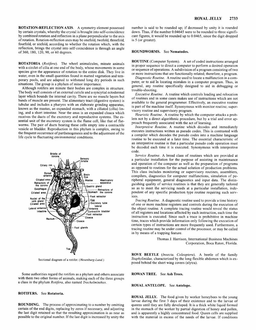
ROTATION-REFLECTION AXIS. A symmetry element possessed by certain crystals, whereby the crystal is brought into self-coincidence by combined rotation and reflection in a plane perpendicular to the axis of rotation. Rotation-reflection axes may be onefold, twofold, threefold, fourfold, or sixfold, according to whether the rotation which, with the reflection, brings the crystal into self-coincidence is through an angle of 360, 180, 120, 90, or 60 degrees.
ROTATORIA (Rotifera). The wheel animalcules, minute animals with a circlet of cilia at one end of the body, whose movements in some species give the appearance of rotation to the entire disk. They live in water, even in the small quantities found in matted vegetation and temporary pools, and are adapted to withstand long dry periods in such situations. The group is a phylum of minor importance.
Although rotifers are minute their bodies are complex in structure. The body wall consists of an external cuticle and a syncytial ectodermal layer which bounds the internal cavity. There are no muscle layers but bands of muscle are present. The alimentary tract (digestive system) is tubular and includes a pharynx with an elaborate grinding apparatus, known as the mastax, an expanded stomach, with a ciliated (cilia) lining, and a short intestine. Near the anus is an expanded cloaca which receives the ducts of the excretory and reproductive systems. The essential unit of the excretory system is the flame cell, like that of flatworms. The pair of ducts bearing these cells empty into a contractile vesicle or bladder. Reproduction in this phylum is complex, owing to the frequent occurrence of parthenogenesis and to the adjustment of the life cycle to fluctuating environmental conditions.
Bristle of corona
·t- ,ualiliiC gland
~~~~ .. ,~-q·:~ :,is -- fletractora of l ·· 1~''""'' """ the corona
Foot retractor Egg Ellcretory tube
lateral Antenna
Contractile bladder lt!f~~~:::;Z: · Foot retractor
Cloaca
Sectional diagram of a rotifer. ( Wesenburg-Lund.)
Some authorities regard the rotifers as a phylum and others associate with them two other forms of animals, making each of the three groups a class in the phylum Rotifera, also named Trochelminthes.
ROTIFERS. See Rotatoria.
ROUNDING. The process of approximating to a number by omitting certain of the end digits, replacing by zeros if necessary, and adjusting the last digit retained so that the resulting approximation is as near as possible to the original number. If the last digit is increased by unity the
ROYAL JELLY 2733
number is said to be rounded up; if decreased by unity it is rounded down. Thus, if the number 0.04645 were to be rounded to three significant figures, it would be rounded up to 0.0465, since the digit dropped is 5 (or greater).
ROUNDWORMS. See Nematodes.
ROUTINE (Computer System). A set of coded instructions arranged in proper sequence to direct a computer to perform a desired operation or sequence of operations. A subdivision of a program consisting of two or more instructions that are functionally related; therefore, a program.
Diagnostic Routine. A routine used to locate a malfunction in a computer, or to aid In locating mistakes in a computer program. Thus, in general, any routine specifically designed to aid in debugging or trouble-shooting.
Executive Routine. A routine which controls loading and relocation of routines and in some cases makes use of instructions which are not available to the general programmer. Effectively, an executive routine is part of the machine itself. Synonymous with monitor routine; supervisory routine and supervisory program.
Heuristic Routine. A routine by which the computer attacks a problem not by a direct algorithmic procedure, but by a trial and error approach frequently associated with the act of learning.
Interpretive Routine. A routine which decodes and immediately executes instructions written as pseudo codes . This is contrasted with a compiler which decodes the pseudo codes into a machine language routine to be executed at a later time. The essential characteristic of an interpretive routine is that a particular pseudo code operation must be decoded each time it is executed. Synonymous with interpretive code.
Service Routine. A broad class of routines which are provided at a particular installation for the purpose of assisting in maintenance and operation of the computer as well as the preparation of programs as opposed to routines for the actual solution of production problems. This class includes monitoring or supervisory routines, assemblers, compilers, diagnostics for computer malfunctions, simulation of peripheral equipment, general diagnostics and input data. The distinguishing quality of service routines is that they are generally tailored so as to meet the servicing needs at a particular installation, independent of any specific production type routine requiring such services.
Tracing Routine. A diagnostic routine used to provide a time history of one or more machine registers and controls during the execution of the object routine. A complete tracing routine would reveal the status of all registers and locations affected by each instruction, each time the instruction is executed. Since such a trace is prohibitive in machine time, traces which provide information only following the execution of certain types of instructions are more frequently used. Furthermore, a tracing routine may be under control of the processor, or may be called in by means of a trapping feature.
Thomas J. Harrison, International Business Machines Corporation, Boca Raton, Florida.
ROVE BEETLE (Insecta, Coleoptera) . A beetle of the family Staphylinidae, characterized by the long flexible abdomen which is exposed behind the short wing covers (elytra).
ROWAN TREE. See Ash Trees.
ROYAL ANTELOPE. See Antelope.
ROYAL JELLY. The food given by worker honeybees to the young larvae during the first 3 days of their existence and to the larvae of queens until they are fully developed. It is a thick white liquid formed in the stomach of the worker by partial digestion of honey and pollen, and is apparently a highly concentrated food . Queen cells are supplied with the material in excess of the needs of the larvae. If conditions
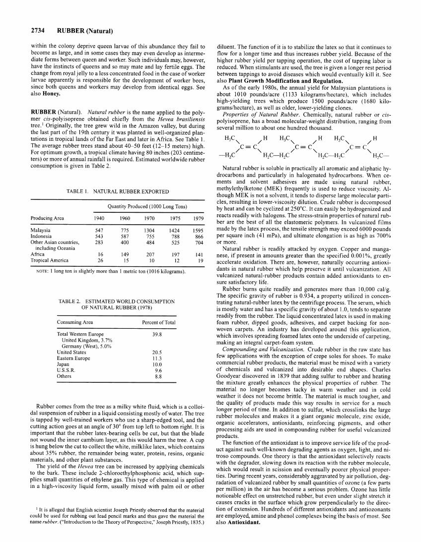
2734 RUBBER (Natural)
within the colony deprive queen larvae of this abundance they fail to become as large, and in some cases they may even develop as intermediate forms between queen and worker. Such individuals may, however, have the instincts of queens and so may mate and lay fertile eggs. The change from royal jelly to a less concentrated food in the case of worker larvae apparently is responsible for the development of worker bees, since both queens and workers may develop from identical eggs. See also Honey.
RUBBER (Natural). Natural rubber is the name applied to the polymer cis-polyisoprene obtained chiefly from the Hevea brasiliensis tree. 1 Originally, the tree grew wild in the Amazon valley, but during the last part of the 19th century it was planted in well-organized plantations in tropical lands of the Far East and later in Africa. See Table 1. The average rubber trees stand about 40-50 feet (12-15 meters) high. For optimum growth, a tropical climate having 80 inches (203 centimeters) or more of annual rainfall is required. Estimated worldwide rubber consumption is given in Table 2.
TABLE I. NATURAL RUBBER EXPORTED
Quantity Produced (1000 Long Tons)
Producing Area 1940 1960 1970 1975
Malaysia 547 775 1304 1424 Indonesia 543 587 755 788 Other Asian countries, 283 400 484 525
including Oceania Africa 16 149 207 197 Tropical America 26 15 10 12
NOTE: I long ton is slightly more than I metric ton (1016 kilograms).
TABLE 2. ESTIMATED WORLD CONSUMPTION OF NATURAL RUBBER (1978)
Consuming Area
Total Western Europe United Kingdom, 3.7% Germany (West), 5.0%
United States Eastern Europe Japan U.S.S.R. Others
Percent of Total
39.8
20.5 11.3 10.0 9.6 8.8
1979
1595 866 704
141 19
Rubber comes from the tree as a milky white fluid, which is a colloidal suspension of rubber in a liquid consisting mostly of water. The tree is tapped by well-trained workers who use a sharp-edged tool, and the cutting action goes at an angle of 30° from top left to bottom right. It is important that the rubber latex-bearing cells be cut, but that the blade not wound the inner cambium layer, as this would harm the tree. A cup is hung below the cut to collect the white, milklike latex, which contains about 35% rubber, the remainder being water, protein, resins, organic materials, and other plant substances.
The yield of the Hevea tree can be increased by applying chemicals to the bark. These include 2-chloroethylphosphonic acid, which supplies small quantities of ethylene gas. This type of chemical is applied in a high-viscosity liquid form, usually mixed with palm oil or other
1 It is alleged that English scientist Joseph Priestly observed that the material could be used for rubbing out lead pencil marks and thus gave the material the name rubber. ("Introduction to the Theory of Perspective," Joseph Priestly, 1835.)
diluent. The function of it is to stabilize the latex so that it continues to flow for a longer time and thus increases rubber yield. Because of the higher rubber yield per tapping operation, the cost of tapping labor is reduced. When stimulants are used, the tree is given a longer rest period between tappings to avoid diseases which would eventually kill it. See also Plant Growth Modification and Regulation.
As of the early 1980s, the annual yield for Malaysian plantations is about 1010 pounds/acre (1133 kilograms/hectare), which includes high-yielding trees which produce 1500 pounds/acre ( 1680 kilograms/hectare), as well as older, lower-yielding clones.
Properties of Natural Rubber. Chemically, natural rubber or cispolyisoprene, has a broad molecular-weight distribution, ranging from several million to about one hundred thousand.
Natural rubber is soluble in practically all aromatic and aliphatic hydrocarbons and particularly in halogenated hydrocarbons. When cements and solvent adhesives are made using natural rubber, methylethylketone (MEK) frequently is used to reduce viscosity. Although MEK is not a solvent, it tends to disperse large molecular particles, resulting in lower-viscosity dilution. Crude rubber is decomposed by heat and can be cyclized at 250°C. It can easily be hydrogenized and reacts readily with halogens. The stress-strain properties of natural rubber are the best of all the elastomeric polymers. In vulcanized films made by the latex process, the tensile strength may exceed 6000 pounds per square inch (41 mPa), and ultimate elongation is as high as 700% or more.
Natural rubber is readily attacked by oxygen. Copper and manganese, if present in amounts greater than the specified 0.001%, greatly accelerate oxidation. There are, however, naturally occurring antioxidants in natural rubber which help preserve it until vulcanization. All vulcanized natural-rubber products contain added antioxidants to ensure satisfactory life.
Rubber burns quite readily and generates more than I 0,000 call g. The specific gravity of rubber is 0.934, a property utilized in concentrating natural-rubber latex by the centrifuge process. The serum, which is mostly water and has a specific gravity of about 1.0, tends to separate readily from the rubber. The liquid concentrated latex is used in making foam rubber, dipped goods, adhesives, and carpet backing for nonwoven carpets. An industry has developed around this application, which involves spreading foamed latex onto the underside of carpeting, making an integral carpet-foam system.
Compounding and Vulcanization. Crude rubber in the raw state has few applications with the exception of crepe soles for shoes. To make commercial rubber products, the material must be mixed with a variety of chemicals and vulcanized into desirable end shapes. Charles Goodyear discovered in 1839 that adding sulfur to rubber and heating the mixture greatly enhances the physical properties of rubber. The material no longer becomes tacky in warm weather and in cold weather it does not become brittle. The material is much tougher, and the quality of products made this way results in service for a much longer period of time. In addition to sulfur, which crosslinks the large rubber molecules and makes it a giant organic molecule, zinc oxide, organic accelerators, antioxidants, reinforcing pigments, and other processing aids are used in compounding rubber for useful vulcanized products.
The function of the antioxidant is to improve service life of the product against such well-known degrading agents as oxygen, light, and nitroso compounds. One theory is that the antioxidant selectively reacts with the degrader, slowing down its reaction with the rubber molecule, which would result in scission and eventually poorer physical properties. During recent years, considerably aggravated by air pollution, degradation of vulcanized rubber by small quantities of ozone (a few parts per million) in the air has become a serious problem. Ozone has little noticeable effect on unstretched rubber, but even under slight stretch it causes cracks in the surface which grow perpendicularly to the qirection of extension. Hundreds of different antioxidants and antiozonants are employed, amine and phenol complexes being ~he basis of most. See also Antioxidant.
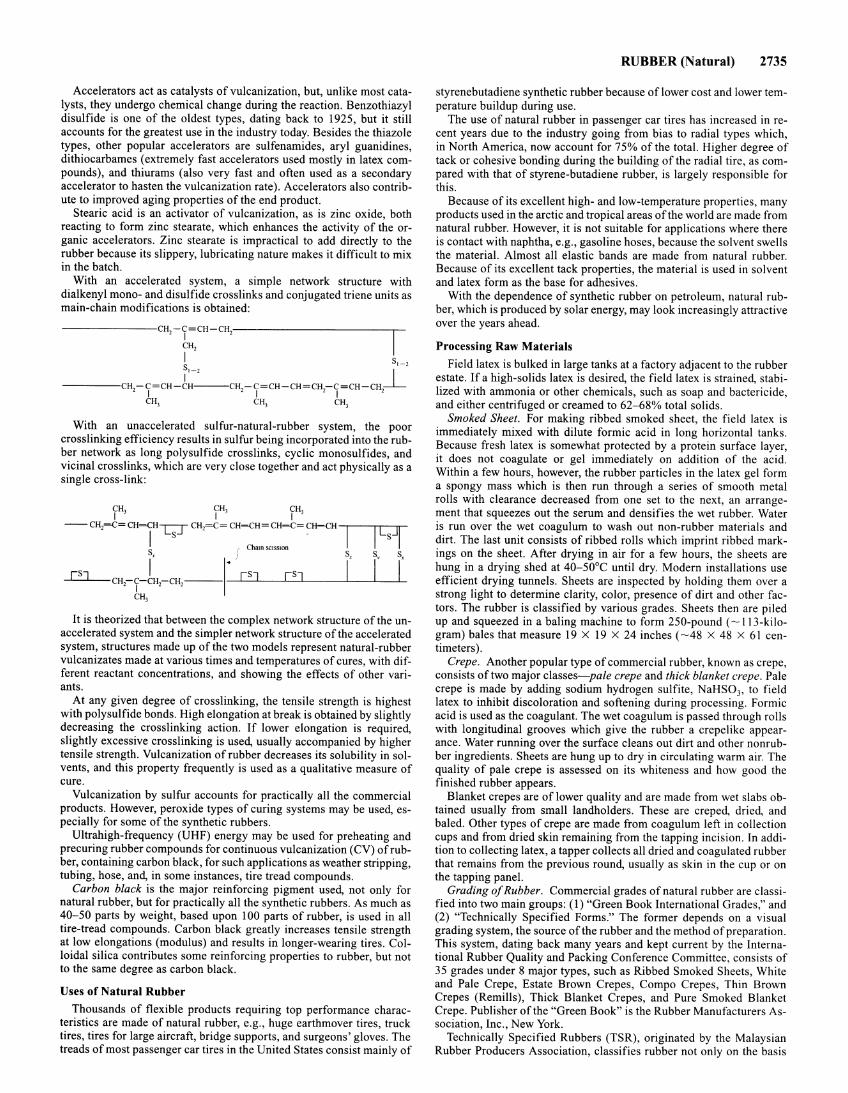
Accelerators act as catalysts of vulcanization, but, unlike most catalysts, they undergo chemical change during the reaction. Benzothiazyl disulfide is one of the oldest types, dating back to 1925, but it still accounts for the greatest use in the industry today. Besides the thiazole types, other popular accelerators are sulfenamides, aryl guanidines, dithiocarbames (extremely fast accelerators used mostly in latex compounds), and thiurams (also very fast and often used as a secondary accelerator to hasten the vulcanization rate). Accelerators also contribute to improved aging properties of the end product.
Stearic acid is an activator of vulcanization, as is zinc oxide, both reacting to form zinc stearate, which enhances the activity of the organic accelerators. Zinc stearate is impractical to add directly to the rubber because its slippery, lubricating nature makes it difficult to mix in the batch.
With an accelerated system, a simple network structure with dialkenyl mono- and disulfide crosslinks and conjugated triene units as main-chain modifications is obtained:
---------------CH2-T=CH-CH2-------------------------,
CH2
I s,~, s,~, _l
---------CH -C=CH-tH---CH -C=CH-CH=CH-C=CH-CH 2 I 2 I , I ,
CH3 CH3 CH3
With an unaccelerated sulfur-natural-rubber system, the poor cross linking efficiency results in sulfur being incorporated into the rubber network as long polysulfide crosslinks, cyclic monosulfides, and vicinal cross links, which are very close together and act physically as a single cross-link:
CH3 CH3 CH3 I I I
__ CH2=C= CH=r-c;r CH,=C= CH=CH= CH-{:= CH=CH 1
S I Cham SCISSIOn Sx
[SJ ,, I.) [SJ [SJ I CH,-T-CH2-CH,-----
CH,
I [s]l S, S,
I I
It is theorized that between the complex network structure of the unaccelerated system and the simpler network structure of the accelerated system, structures made up of the two models represent natural-rubber vulcanizates made at various times and temperatures of cures, with different reactant concentrations, and showing the effects of other variants.
At any given degree of crosslinking, the tensile strength is highest with polysulfide bonds. High elongation at break is obtained by slightly decreasing the crosslinking action. If lower elongation is required, slightly excessive crosslinking is used, usually accompanied by higher tensile strength. Vulcanization of rubber decreases its solubility in solvents, and this property frequently is used as a qualitative measure of cure.
Vulcanization by sulfur accounts for practically all the commercial products. However, peroxide types of curing systems may be used, especially for some of the synthetic rubbers.
Ultrahigh-frequency (UHF) energy may be used for preheating and precuring rubber compounds for continuous vulcanization (CV) of rubber, containing carbon black, for such applications as weather stripping, tubing, hose, and, in some instances, tire tread compounds.
Carbon black is the major reinforcing pigment used, not only for natural rubber, but for practically all the synthetic rubbers. As much as 40-50 parts by weight, based upon 100 parts of rubber, is used in all tire-tread compounds. Carbon black greatly increases tensile strength at low elongations (modulus) and results in longer-wearing tires. Colloidal silica contributes some reinforcing properties to rubber, but not to the same degree as carbon black.
Uses of Natural Rubber Thousands of flexible products requiring top performance charac
teristics are made of natural rubber, e.g., huge earthmover tires, truck tires, tires for large aircraft, bridge supports, and surgeons' gloves. The treads of most passenger car tires in the United States consist mainly of
RUBBER (Natural) 2735
styrene butadiene synthetic rubber because of lower cost and lower temperature buildup during use.
The use of natural rubber in passenger car tires has increased in recent years due to the industry going from bias to radial types which, in North America, now account for 75% of the total. Higher degree of tack or cohesive bonding during the building of the radial tire, as compared with that of styrene-butadiene rubber, is largely responsible for this.
Because of its excellent high- and low-temperature properties, many products used in the arctic and tropical areas of the world are made from natural rubber. However, it is not suitable for applications where there is contact with naphtha, e.g., gasoline hoses, because the solvent swells the material. Almost all elastic bands are made from natural rubber. Because of its excellent tack properties, the material is used in solvent and latex form as the base for adhesives.
With the dependence of synthetic rubber on petroleum, natural rubber, which is produced by solar energy, may look increasingly attractive over the years ahead.
Processing Raw Materials Field latex is bulked in large tanks at a factory adjacent to the rubber
estate. If a high-solids latex is desired, the field latex is strained, stabilized with ammonia or other chemicals, such as soap and bactericide, and either centrifuged or creamed to 62-68% total solids.
Smoked Sheet. For making ribbed smoked sheet, the field latex is immediately mixed with dilute formic acid in long horizontal tanks. Because fresh latex is somewhat protected by a protein surface layer, it does not coagulate or gel immediately on addition of the acid. Within a few hours, however, the rubber particles in the latex gel form a spongy mass which is then run through a series of smooth metal rolls with clearance decreased from one set to the next, an arrangement that squeezes out the serum and densifies the wet rubber. Water is run over the wet coagulum to wash out non-rubber materials and dirt. The last unit consists of ribbed rolls which imprint ribbed markings on the sheet. After drying in air for a few hours, the sheets are hung in a drying shed at 40-50°C until dry. Modern installations use efficient drying tunnels. Sheets are inspected by holding them over a strong light to determine clarity, color, presence of dirt and other factors. The rubber is classified by various grades. Sheets then are piled up and squeezed in a baling machine to form 250-pound ( ~ 113-kilogram) bales that measure 19 X 19 X 24 inches ( ~48 X 48 X 61 centimeters).
Crepe. Another popular type of commercial rubber, known as crepe, consists of two major classes--pale crepe and thick blanket crepe. Pale crepe is made by adding sodium hydrogen sulfite, NaHS03, to field latex to inhibit discoloration and softening during processing. Formic acid is used as the coagulant. The wet coagulum is passed through rolls with longitudinal grooves which give the rubber a crepelike appearance. Water running over the surface cleans out dirt and other nonrubber ingredients. Sheets are hung up to dry in circulating warm air. The quality of pale crepe is assessed on its whiteness and how good the finished rubber appears.
Blanket crepes are of lower quality and are made from wet slabs obtained usually from small landholders. These are creped, dried, and baled. Other types of crepe are made from coagulum left in collection cups and from dried skin remaining from the tapping incision. In addition to collecting latex, a tapper collects all dried and coagulated rubber that remains from the previous round, usually as skin in the cup or on the tapping panel.
Grading of Rubber. Commercial grades of natural rubber are classified into two main groups: (1) "Green Book International Grades," and (2) "Technically Specified Forms." The former depends on a visual grading system, the source of the rubber and the method of preparation. This system, dating back many years and kept current by the International Rubber Quality and Packing Conference Committee, consists of 35 grades under 8 major types, such as Ribbed Smoked Sheets, White and Pale Crepe, Estate Brown Crepes, Compo Crepes, Thin Brown Crepes (Remills), Thick Blanket Crepes, and Pure Smoked Blanket Crepe. Publisher of the "Green Book" is the Rubber Manufacturers Association, Inc., New York.
Technically Specified Rubbers (TSR), originated by the Malaysian Rubber Producers Association, classifies rubber not only on the basis
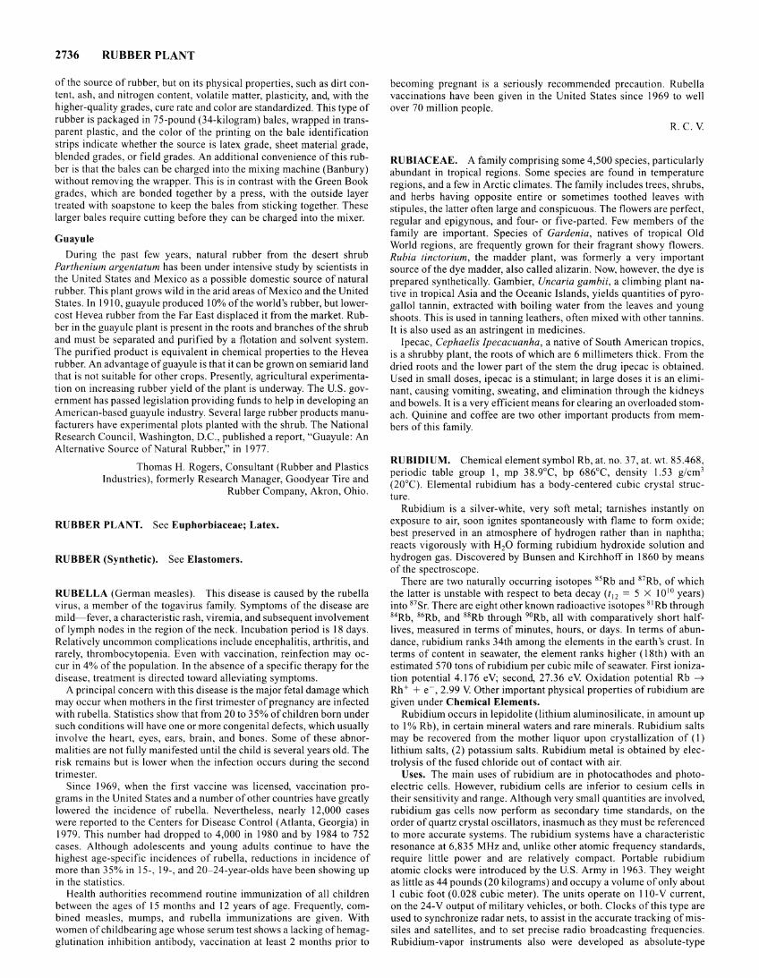
2736 RUBBER PLANT
of the source of rubber, but on its physical properties, such as dirt content, ash, and nitrogen content, volatile matter, plasticity, and, with the higher-quality grades, cure rate and color are standardized. This type of rubber is packaged in 75-pound (34-kilogram) bales, wrapped in transparent plastic, and the color of the printing on the bale identification strips indicate whether the source is latex grade, sheet material grade, blended grades, or field grades. An additional convenience of this rubber is that the bales can be charged into the mixing machine (Banbury) without removing the wrapper. This is in contrast with the Green Book grades, which are bonded together by a press, with the outside layer treated with soapstone to keep the bales from sticking together. These larger bales require cutting before they can be charged into the mixer.
Guayule
During the past few years, natural rubber from the desert shrub Parthenium argenta tum has been under intensive study by scientists in the United States and Mexico as a possible domestic source of natural rubber. This plant grows wild in the arid areas of Mexico and the United States. In 1910, guayule produced I 0% of the world's rubber, but lowercost Hevea rubber from the Far East displaced it from the market. Rubber in the guayule plant is present in the roots and branches of the shrub and must be separated and purified by a flotation and solvent system. The purified product is equivalent in chemical properties to the Hevea rubber. An advantage of guayule is that it can be grown on semiarid land that is not suitable for other crops. Presently, agricultural experimentation on increasing rubber yield of the plant is underway. The U.S. government has passed legislation providing funds to help in developing an American-based guayule industry. Several large rubber products manufacturers have experimental plots planted with the shrub. The National Research Council, Washington, D.C., published a report, "Guayule: An Alternative Source of Natural Rubber," in 1977.
Thomas H. Rogers, Consultant (Rubber and Plastics Industries), formerly Research Manager, Goodyear Tire and
Rubber Company, Akron, Ohio.
RUBBER PLANT. See Euphorbiaceae; Latex.
RUBBER (Synthetic). See Elastomers.
RUBELLA (German measles). This disease is caused by the rubella virus, a member of the togavirus family. Symptoms of the disease are mild-fever, a characteristic rash, viremia, and subsequent involvement of lymph nodes in the region of the neck. Incubation period is 18 days. Relatively uncommon complications include encephalitis, arthritis, and rarely, thrombocytopenia. Even with vaccination, reinfection may occur in 4% of the population. In the absence of a specific therapy for the disease, treatment is directed toward alleviating symptoms.
A principal concern with this disease is the major fetal damage which may occur when mothers in the first trimester of pregnancy are infected with rubella. Statistics show that from 20 to 35% of children born under such conditions will have one or more congenital defects, which usually involve the heart, eyes, ears, brain, and bones. Some of these abnormalities are not fully manifested until the child is several years old. The risk remains but is lower when the infection occurs during the second trimester.
Since 1969, when the first vaccine was licensed, vaccination programs in the United States and a number of other countries have greatly lowered the incidence of rubella. Nevertheless, nearly 12,000 cases were reported to the Centers for Disease Control (Atlanta, Georgia) in 1979. This number had dropped to 4,000 in 1980 and by 1984 to 752 cases. Although adolescents and young adults continue to have the highest age-specific incidences of rubella, reductions in incidence of more than 35% in 15-, 19-, and 20-24-year-olds have been showing up in the statistics.
Health authorities recommend routine immunization of all children between the ages of 15 months and 12 years of age. Frequently, combined measles, mumps, and rubella immunizations are given. With women of childbearing age whose serum test shows a lacking of hemagglutination inhibition antibody, vaccination at least 2 months prior to
becoming pregnant is a seriously recommended precaution. Rubella vaccinations have been given in the United States since 1969 to well over 70 million people.
R.C.V
RUBIACEAE. A family comprising some 4,500 species, particularly abundant in tropical regions. Some species are found in temperature regions, and a few in Arctic climates. The family includes trees, shrubs, and herbs having opposite entire or sometimes toothed leaves with stipules, the latter often large and conspicuous. The flowers are perfect, regular and epigynous, and four- or five-parted. Few members of the family are important. Species of Gardenia, natives of tropical Old World regions, are frequently grown for their fragrant showy flowers. Rubia tinctorium, the madder plant, was formerly a very important source of the dye madder, also called alizarin. Now, however. the dye is prepared synthetically. Gambier, Uncaria gambii, a climbing plant native in tropical Asia and the Oceanic Islands, yields quantities of pyrogallol tannin, extracted with boiling water from the leaves and young shoots. This is used in tanning leathers, often mixed with other tannins. It is also used as an astringent in medicines.
Ipecac, Cephaelis Ipecacuanha, a native of South American tropics, is a shrubby plant, the roots of which are 6 millimeters thick. From the dried roots and the lower part of the stem the drug ipecac is obtained. Used in small doses, ipecac is a stimulant; in large doses it is an eliminant, causing vomiting, sweating, and elimination through the kidneys and bowels. It is a very efficient means for clearing an overloaded stomach. Quinine and coffee are two other important products from members of this family.
RUBIDIUM. Chemical element symbol Rb, at. no. 37, at. wt. 85.468, periodic table group I, mp 38.9°C, bp 686°C, density 1.53 g/cm3
(20°C). Elemental rubidium has a body-centered cubic crystal structure.
Rubidium is a silver-white, very soft metal; tarnishes instantly on exposure to air, soon ignites spontaneously with flame to form oxide; best preserved in an atmosphere of hydrogen rather than in naphtha; reacts vigorously with H20 forming rubidium hydroxide solution and hydrogen gas. Discovered by Bunsen and Kirchhoff in 1860 by means of the spectroscope.
There are two naturally occurring isotopes s5Rb and 87Rb, of which the latter is unstable with respect to beta decay (t 12 = 5 X I 0 10 years) into 87Sr. There are eight other known radioactive isotopes 81 Rb through 84Rb, 86Rb, and 88 Rb through 90Rb, all with comparatively short halflives, measured in terms of minutes, hours, or days. In terms of abundance, rubidium ranks 34th among the elements in the earth's crust. In terms of content in seawater, the element ranks higher (18th) with an estimated 570 tons of rubidium per cubic mile of seawater. First ionization potential 4.176 eV; second, 27.36 eV Oxidation potential Rb --7
Rh + + e-, 2.99 V Other important physical properties of rubidium are given under Chemical Elements.
Rubidium occurs in lepidolite (lithium aluminosilicate, in amount up to I% Rb ), in certain mineral waters and rare minerals. Rubidium salts may be recovered from the mother liquor upon crystallization of (I) lithium salts, (2) potassium salts. Rubidium metal is obtained by electrolysis of the fused chloride out of contact with air.
Uses. The main uses of rubidium are in photocathodes and photoelectric cells. However, rubidium cells are inferior to cesium cells in their sensitivity and range. Although very small quantities are involved, rubidium gas cells now perform as secondary time standards, on the order of quartz crystal oscillators, inasmuch as they must be referenced to more accurate systems. The rubidium systems have a characteristic resonance at 6,835 MHz and, unlike other atomic frequency standards, require little power and are relatively compact. Portable rubidium atomic clocks were introduced by the U.S. Army in 1963. They weight as little as 44 pounds (20 kilograms) and occupy a volume of only about I cubic foot (0.028 cubic meter). The units operate on II 0-V current, on the 24-V output of military vehicles, or both. Clocks of this type are used to synchronize radar nets, to assist in the accurate tracking of missiles and satellites, and to set precise radio broadcasting frequencies. Rubidium-vapor instruments also were developed as absolute-type
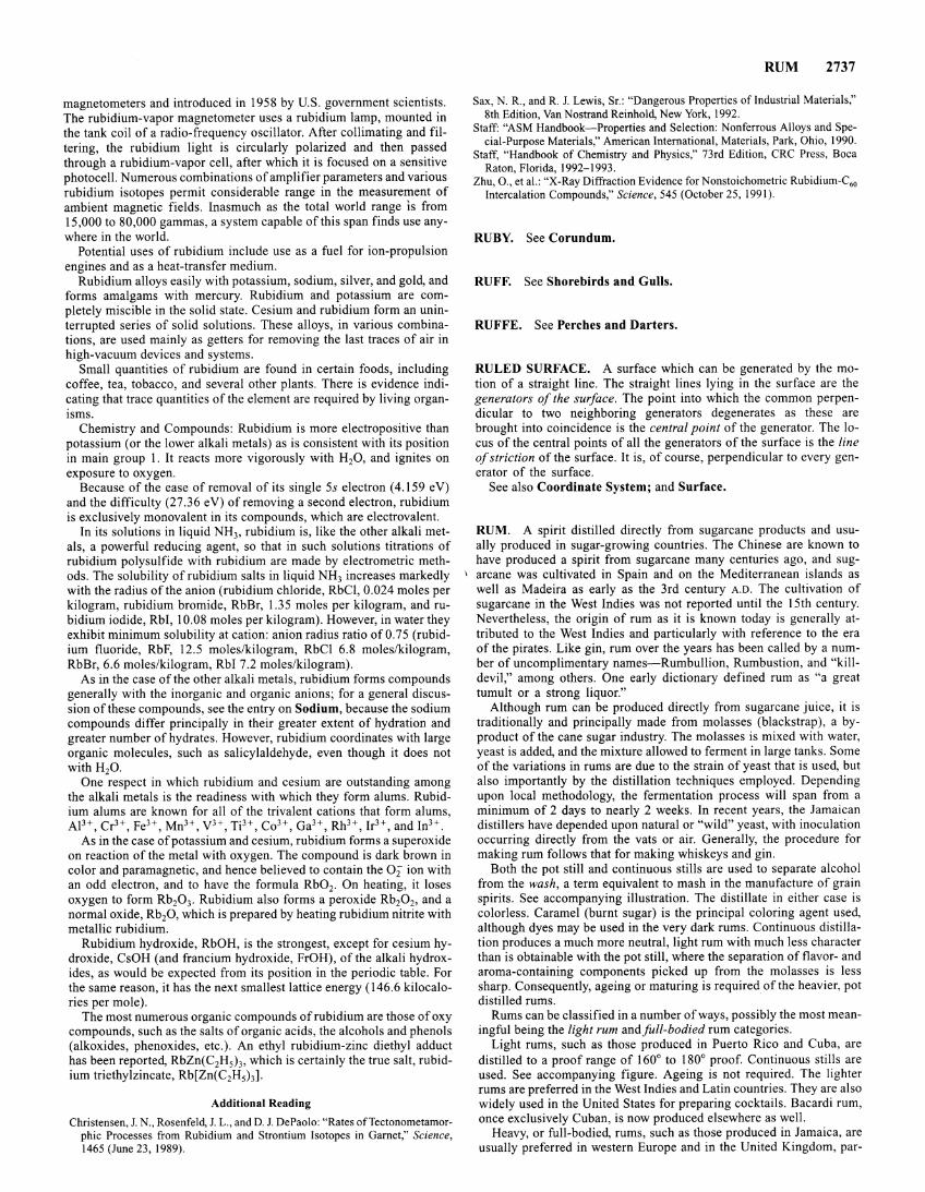
magnetometers and introduced in 1958 by U.S. government scientists. The rubidium-vapor magnetometer uses a rubidium lamp, mounted in the tank coil of a radio-frequency oscillator. After collimating and filtering, the rubidium light is circularly polarized and then passed through a rubidium-vapor cell, after which it is focused on a sensitive photocell. Numerous combinations of amplifier parameters and various rubidium isotopes permit considerable range in the measurement of ambient magnetic fields. Inasmuch as the total world range is from 15,000 to 80,000 gammas, a system capable of this span finds use anywhere in the world.
Potential uses of rubidium include use as a fuel for ion-propulsion engines and as a heat-transfer medium.
Rubidium alloys easily with potassium, sodium, silver, and gold, and forms amalgams with mercury. Rubidium and potassium are completely miscible in the solid state. Cesium and rubidium form an uninterrupted series of solid solutions. These alloys, in various combinations, are used mainly as getters for removing the last traces of air in high-vacuum devices and systems.
Small quantities of rubidium are found in certain foods, including coffee, tea, tobacco, and several other plants. There is evidence indicating that trace quantities of the element are required by living organisms.
Chemistry and Compounds: Rubidium is more electropositive than potassium (or the lower alkali metals) as is consistent with its position in main group 1. It reacts more vigorously with H20, and ignites on exposure to oxygen.
Because of the ease of removal of its single Ss electron ( 4.159 e V) and the difficulty (27.36 eV) of removing a second electron, rubidium is exclusively monovalent in its compounds, which are electrovalent.
In its solutions in liquid NH3, rubidium is, like the other alkali metals, a powerful reducing agent, so that in such solutions titrations of rubidium polysulfide with rubidium are made by electrometric methods. The solubility of rubidium salts in liquid NH3 increases markedly with the radius of the anion (rubidium chloride, RbCI, 0.024 moles per kilogram, rubidium bromide, RbBr, 1.35 moles per kilogram, and rubidium iodide, Rbi, I 0.08 moles per kilogram). However, in water they exhibit minimum solubility at cation: anion radius ratio of0.75 (rubidium fluoride, RbF, 12.5 moles/kilogram, RbCI 6.8 moles/kilogram, RbBr, 6.6 moles/kilogram, Rbi 7.2 moles/kilogram).
As in the case of the other alkali metals, rubidium forms compounds generally with the inorganic and organic anions; for a general discussion of these compounds, see the entry on Sodium, because the sodium compounds differ principally in their greater extent of hydration and greater number of hydrates. However, rubidium coordinates with large organic molecules, such as salicylaldehyde, even though it does not with H20.
One respect in which rubidium and cesium are outstanding among the alkali metals is the readiness with which they form alums. Rubidium alums are known for all of the trivalent cations that form alums, AJ3+, Cr3+, feH, MnH, yH, Ti3+, Co3+, GaH, Rh3+, IrH, and lnH.
As in the case of potassium and cesium, rubidium forms a superoxide on reaction of the metal with oxygen. The compound is dark brown in color and paramagnetic, and hence believed to contain the 02 ion with an odd electron, and to have the formula Rb02. On heating, it loses oxygen to form Rb20 3• Rubidium also forms a peroxide Rb20 2, and a normal oxide, Rb20, which is prepared by heating rubidium nitrite with metallic rubidium.
Rubidium hydroxide, RbOH, is the strongest, except for cesium hydroxide, CsOH (and francium hydroxide, FrOH), of the alkali hydroxides, as would be expected from its position in the periodic table. For the same reason, it has the next smallest lattice energy (146.6 kilocalories per mole).
The most numerous organic compounds of rubidium are those of oxy compounds, such as the salts of organic acids, the alcohols and phenols (alkoxides, phenoxides, etc.). An ethyl rubidium-zinc diethyl adduct has been reported, RbZn(C2H5h, which is certainly the true salt, rubidium triethylzincate, Rb[Zn(C2H5h].
Additional Reading
Christensen, J. N., Rosenfeld, J. L., and D. J. DePaolo: "Rates ofTectonometamorphic Processes from Rubidium and Strontium Isotopes in Garnet," Science, 1465 (June 23, 1989).
RUM 2737
Sax, N. R., and R. J. Lewis, Sr.: "Dangerous Properties of Industrial Materials," 8th Edition, Van Nostrand Reinhold, New York, 1992.
Staff: "ASM Handbook-Properties and Selection: Nonferrous Alloys and Special-Purpose Materials," American International, Materials, Park, Ohio, 1990.
Staff, "Handbook of Chemistry and Physics," 73rd Edition, CRC Press, Boca Raton, Florida, 1992-1993.
Zhu, 0., et al.: "X-Ray Diffraction Evidence for Nonstoichometric Rubidium-C60
Intercalation Compounds," Science, 545 (October 25, 1991).
RUBY. See Corundum.
RUFF. See Shorebirds and Gulls.
RUFFE. See Perches and Darters.
RULED SURFACE. A surface which can be generated by the motion of a straight line. The straight lines lying in the surface are the generators of the surface. The point into which the common perpendicular to two neighboring generators degenerates as these are brought into coincidence is the central point of the generator. The locus of the central points of all the generators of the surface is the line of striction of the surface. It is, of course, perpendicular to every generator of the surface.
See also Coordinate System; and Surface.
RUM. A spirit distilled directly from sugarcane products and usually produced in sugar-growing countries. The Chinese are known to have produced a spirit from sugarcane many centuries ago, and sug-
1 arcane was cultivated in Spain and on the Mediterranean islands as well as Madeira as early as the 3rd century A.D. The cultivation of sugarcane in the West Indies was not reported until the 15th century. Nevertheless, the origin of rum as it is known today is generally attributed to the West Indies and particularly with reference to the era of the pirates. Like gin, rum over the years has been called by a number of uncomplimentary names-Rumbullion, Rumbustion, and "killdevil," among others. One early dictionary defined rum as "a great tumult or a strong liquor."
Although rum can be produced directly from sugarcane juice, it is traditionally and principally made from molasses (blackstrap ), a byproduct of the cane sugar industry. The molasses is mixed with water, yeast is added, and the mixture allowed to ferment in large tanks. Some of the variations in rums are due to the strain of yeast that is used, but also importantly by the distillation techniques employed. Depending upon local methodology, the fermentation process will span from a minimum of 2 days to nearly 2 weeks. In recent years, the Jamaican distillers have depended upon natural or "wild" yeast, with inoculation occurring directly from the vats or air. Generally, the procedure for making rum follows that for making whiskeys and gin.
Both the pot still and continuous stills are used to separate alcohol from the wash, a term equivalent to mash in the manufacture of grain spirits. See accompanying illustration. The distillate in either case is colorless. Caramel (burnt sugar) is the principal coloring agent used, although dyes may be used in the very dark rums. Continuous distillation produces a much more neutral, light rum with much less character than is obtainable with the pot still, where the separation of flavor- and aroma-containing components picked up from the molasses is less sharp. Consequently, ageing or maturing is required of the heavier, pot distilled rums.
Rums can be classified in a number of ways, possibly the most meaningful being the light rum and full-bodied rum categories.
Light rums, such as those produced in Puerto Rico and Cuba, are distilled to a proof range of 160° to 180° proof. Continuous stills are used. See accompanying figure. Ageing is not required. The lighter rums are preferred in the West Indies and Latin countries. They are also widely used in the United States for preparing cocktails. Bacardi rum, once exclusively Cuban, is now produced elsewhere as well.
Heavy, or full-bodied, rums, such as those produced in Jamaica, are usually preferred in western Europe and in the United Kingdom, par-
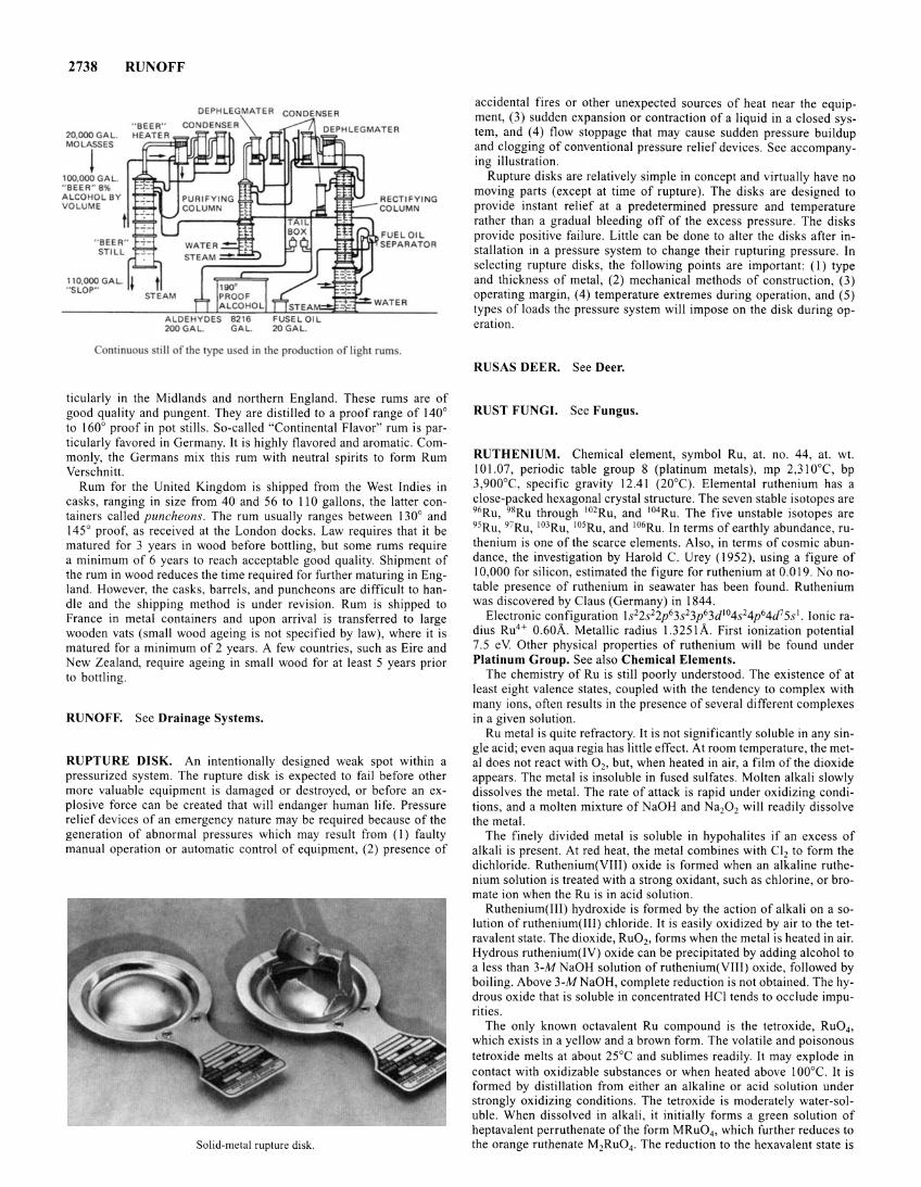
2738 RUNOFF
20,000 GAL. MOLASSES
! 100,000 GAL. " BEER" 8% ALCOHOL BY VOLUME
" BEER" STILL
110,000 GAL. " SLOP"
DEPHLEGMATER CONDENSER
ALDEHYDES 8216 200 GAL GAL.
RECTIFYING COLUMN
FUEL OIL SEPARATOR
ontinuou till of the type u ed in the production of light rum .
ticularly in the Midlands and northern England. These rums are of good quality and pungent. They are distilled to a proof range of 140° to 160° proof in pot stills. So-called "Continental Flavor" rum is particularly favored in Germany. It is highly flavored and aromatic. Commonly, the Germans mix this rum with neutral spirits to form Rum Verschnitt.
Rum for the United Kingdom is shipped from the West Indies in casks, ranging in size from 40 and 56 to 110 gallons, the latter containers called puncheons. The rum usually ranges between 130° and 145° proof, as received at the London docks. Law requires that it be matured for 3 years in wood before bottling, but some rums require a minimum of 6 years to reach acceptable good quality. Shipment of the rum in wood reduces the time required for further maturing in England. However, the casks, barrels, and puncheons are difficult to handle and the shipping method is under revision. Rum is shipped to France in metal containers and upon arrival is transferred to large wooden vats (small wood ageing is not specified by law), where it is matured for a minimum of 2 years. A few countries, such as Eire and New Zealand, require ageing in small wood for at least 5 years prior to bottling.
RUNOFF. See Drainage Systems.
RUPTURE DISK. An intentionally designed weak spot within a pressurized system. The rupture disk is expected to fail before other more valuable equipment is damaged or destroyed, or before an explosive force can be created that will endanger human life. Pressure relief devices of an emergency nature may be required because of the generation of abnormal pressures which may result from (I) faulty manual operation or automatic control of equipment, (2) presence of
Solid-metal rupture disk.
accidental fires or other unexpected sources of heat near the equipment, (3) sudden expansion or contraction of a liquid in a closed system, and ( 4) flow stoppage that may cause sudden pressure buildup and clogging of conventional pressure relief devices. See accompanying illustration.
Rupture disks are relatively simple in concept and virtually have no moving parts (except at time of rupture). The disks are designed to provide instant relief at a predetermined pressure and temperature rather than a gradual bleeding off of the excess pressure. The disks provide positive failure. Little can be done to alter the disks after installation in a pressure system to change their rupturing pressure. In selecting rupture disks, the following points are important: (I) type and thickness of metal, (2) mechanical methods of construction, (3) operating margin, (4) temperature extremes during operation, and (5) types of loads the pressure system will impose on the disk during operation.
RUSAS DEER. See Deer.
RUST FUNGI. See Fungus.
RUTHENIUM. Chemical element, symbol Ru, at. no. 44, at. wt. 101.07, periodic table group 8 (platinum metals), mp 2,31 0°C, bp 3,900°C, specific gravity 12.41 (20°C). Elemental ruthenium has a close-packed hexagonal crystal structure. The seven stable isotopes are 96Ru, 98Ru through 102Ru, and 104Ru. The five unstable isotopes are 95Ru, 97Ru, 103Ru, 105Ru, and 106Ru. In terms of earthly abundance, ruthenium is one of the scarce elements. Also, in terms of cosmic abundance, the investigation by Harold C. Urey (1952), using a figure of 10,000 for silicon, estimated the figure for ruthenium at 0.0 19. No notable presence of ruthenium in seawater has been found. Ruthenium was discovered by Claus (Germany) in 1844.
Electronic configuration ls22s22p63s23p63d104s24p64d75s1. Ionic radius Ru4 + 0.60A. Metallic radius 1.3251A. First ionization potential 7.5 eV Other physical properties of ruthenium will be found under Platinum Group. See also Chemical Elements.
The chemistry of Ru is still poorly understood. The existence of at least eight valence states, coupled with the tendency to complex with many ions, often results in the presence of several different complexes in a given solution.
Ru metal is quite refractory. It is not significantly soluble in any single acid; even aqua regia has little effect. At room temperature, the metal does not react with 0 2, but, when heated in air, a film of the dioxide appears. The metal is insoluble in fused sulfates. Molten alkali slowly dissolves the metal. The rate of attack is rapid under oxidizing conditions, and a molten mixture ofNaOH and Nap2 will readily dissolve the metal.
The finely divided metal is soluble in hypohalites if an excess of alkali is present. At red heat, the metal combines with Cl2 to form the dichloride. Ruthenium(VIII) oxide is formed when an alkaline ruthenium solution is treated with a strong oxidant, such as chlorine, or bromate ion when the Ru is in acid solution.
Ruthenium(III) hydroxide is formed by the action of alkali on a solution of ruthenium(III) chloride. It is easily oxidized by air to the tetravalent state. The dioxide, Ru02, forms when the metal is heated in air. Hydrous ruthenium( IV) oxide can be precipitated by adding alcohol to a less than 3-M NaOH solution of ruthenium(VIII) oxide, followed by boiling. Above 3-MNaOH, complete reduction is not obtained. The hydrous oxide that is soluble in concentrated HCI tends to occlude impurities.
The only known octavalent Ru compound is the tetroxide, Ru04 ,
which exists in a yellow and a brown form. The volatile and poisonous tetroxide melts at about 25°C and sublimes readily. It may explode in contact with oxidizable substances or when heated above 1 00°C. It is formed by distillation from either an alkaline or acid solution under strongly oxidizing conditions. The tetroxide is moderately water-soluble. When dissolved in alkali, it initially forms a green solution of heptavalent perruthenate of the form MRu04 , which further reduces to the orange ruthenate M2Ru04• The reduction to the hexavalent state is
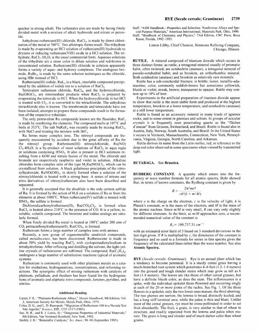
quicker in strong alkali. The ruthenates also are made by fusing finely divided metal with a mixture of alkali hydroxide and nitrate or peroxide.
Anhydrous ruthenium( [II) chloride, RuCI3, is made by direct chlorination of the metal at 700°C. Two allotropic forms result. The trihydrate is made by evaporating an HCI solution ofruthenium(III) hydroxide to dryness or reducing ruthenium(VIII) oxide in a HCI solution. The trihydrate, RuCI3·3H20, is the usual commercial form. Aqueous solutions of the trihydrate are a straw color in dilute solution and red-brown in concentrated solution. Ruthenium(Ill) chloride in solution apparently forms a variety of aquo- and hydroxy complexes. The analogous bromide, RuBr3, is made by the same solution techniques as the chloride, using HBr instead of HCI.
Ruthenium(III) iodide, Rui3, is a black, insoluble compound precipitated by the addition of iodide ion to a solution of RuC13.
Tetravalent ruthenium chloride, RuCI4 , and the hydroxychloride, Ru(OH)Cl3, are intermediate products when RuCI3 is prepared by evaporating the tetroxide in HCI. When the hydroxychloride in hot HCI is treated with Cl2, it is converted to the tetrachloride. The anhydrous tetrachloride also is known. The tetrabromide and tetraiodide have not been isolated; attempts to prepare these compounds result in the formation of the respective trihalides.
The only pentavalent Ru compounds known are the fluorides; RuF5
is made by combining the elements. The compound melts at I 07°C and boils at 3!3°C. The salt NaRuF6 was recently made by mixing RuCI3,
with NaCI and treating the mixture with BrF3.
Ru forms many complex ions. The nitrosyl compounds are frequently encountered by accident due to the great affinity of Ru for the nitrosyl group. Ruthenium(III) nitrosylchloride, Ru(NO) Cl3·4H20, is a by-product of most solutions of RuCI3 in aqua regia or solutions containing HN03. It also is present in HCI solutions resulting from a KOH and nitrate fusion of the metal. The chloride and bromide are respectively raspberry and violet in solution. Alkaline chlorides form complex salts of the type M2Ru(NO)Cl5, which can be crystallized from solution. A black gelatinous precipitate of the nitrosylhydroxide, RuNO(OH)3, is slowly formed when a solution of the nitrosylchloride is heated with a strong base. A series of nitrato and nitro derivatives of nitrosylruthenium also have been described and separated.
It is generally accepted that the disulfide is the only certain sulfide ofRu. It is formed by the action of H2S on a solution of Ru or from the elements at about I 000°C. When ruthenium(IV) sulfide is treated with HN03, the sulfate is formed.
Dichlorodicarbonylruthenium(Il), Ru(COhClb is formed when RuCI3 is heated above 21 ooc in the presence of CO. It is a yellow, insoluble, volatile compound. The bromine and iodine analogs are similarly formed.
When finely divided Ru metal is heated at 180°C under 200 atm of CO, pentacarbonylruthenium(O), Ru(C0)5, is formed.
Ruthenium forms a large number of complex ions with amines. Recently, a new group of organometallic sandwich compounds,
called metallocenes, has been discovered. Ruthenocene is made in about 50% yield by reacting RuCI3 with cyclopentadienylsodium in tetrahydrofuran. After refluxing and distilling the solvent, the light-yellow crystals of ruthenocene are sublimed. The compound, Ru(C5H5h, undergoes a large number of substitution reactions typical of aromatic systems.
Ruthenium is commonly used with other platinum metals as a catalyst for oxidations, hydrogenations, isomerizations, and reforming reactions. The synergetic effect of mixing ruthenium with catalysts of platinum, palladium, and rhodium has been found for the hydrogenations of aromatic and aliphatic nitro compounds, ketones, pyridine, and nitriles.
Additional Reading
Carter, F. E.: "Platinum-Ruthenium Alloys," Metals Handbook, 9th Edition, Vol. 2, American Society for Metals, Metals Park, Ohio, 1979.
Coles, D. G., and L. D. Ramspott: "Migration ofRuthenium-106 in a Nevada Test Site Aquifer," Science, 215, 1235-1237 (1982).
Sax, N. R., and R. J. Lewis, Sr.: "Dangerous Properties of Industrial Materials," 8th Edition, Van Nostrand Reinhold, New York, 1992.
Sinfelt, J. H.: "Bimetallic Catalysts," Sci. A mer., 90-98 (September 1985).
RYE (Secale cereale; Gramineae) 2739
Staff: "ASM Handbook-Properties and Selection: Nonferrous Alloys and Special-Purpose Materials," American International, Materials Park, Ohio, 1990.
Staff, "Handbook of Chemistry and Physics," 73rd Edition, CRC Press, Boca Raton, Florida, 1992-1993.
Linton Libby, Chief Chemist, Simmons Refining Company, Chicago, Illinois.
RUTILE. A mineral composed of titanium dioxide which occurs in three distinct forms: as rutile, a tetragonal mineral usually of prismatic habit, often twinned; are octahedrite (anatase), a tetragonal mineral of pseudo-octahedral habit; and as brookite, an orthorhombic mineral. Both octahedrite (anatase) and brookite as relatively rare minerals.
Rutile has a sub-conchoidal fracture; is brittle; luster, metallic-adamantine; color, commonly reddish-brown but sometimes yellowish, bluish or violet; streak, brown; transparent to opaque. Rutile may contain up to I 0% of iron.
Experiments in the artificial preparation of titanium dioxide appear to show that rutile is the most stable form and produced at the highest temperature, brookite at a lower temperature, and octahedrite (anatase) at a still lower temperature.
Rutile is found as an accessory mineral in many kinds of igneous rocks, and to some extent in gneisses and schists. In groups of acicular crystals it is frequently seen penetrating quartz as the "fleches d'amour" from Orisons, Switzerland, and Brazil. Rutile is found also in Austria, Italy, Norway, South Australia, and Brazil. In the United States it occurs in Vermont, Massachusetts, Connecticut, New York, Pennsylvania, Virginia, Georgia, North Carolina, and Arkansas.
Rutile derives its name from the Latin rutilus, red, in reference to the deep red color observed in some specimens when viewed by transmitted light.
RUTABAGA. See Brassica.
RYDBERG CONSTANT. A quantity which enters into the frequency or wave number formula for all atomic spectra. Bohr showed that, in terms of known constants, the Rydberg constant is given by
2TI 2me4 R=~~-~-
ch 3 (1 + m/ M)
where e is the charge on the electron, c is the velocity of light, h is Planck's constant, m is the mass of the electron, and M is the mass of the atomic nucleus. Since m/M is very small, R can vary only slightly for different elements. In the limit, as m/M approaches zero, a recommended numerical value of the constant is
R~= 109,737.31 cm- 1
with an estimated error limit of 3 based on 3 standard deviations in the last digit given. If R is multiplied by c, the dimension of the constant is frequency and so used in a formula for series in line spectra gives the frequency of the calculated lines rather than the wave number. See also Atomic Spectra.
RYE (Secale cereale; Gramineae). Rye is an annual plant which has a tendency to become perennial. It is a sturdy cereal grass having a much-branched root system which penetrates 4-6 feet ( 1.2-1 .8 meters) into the ground and tough slender stems which may grow as tall as 6 feet (1.8 meters). The leaves are like those of other cereal grasses, but have a definite bluish color, as does the stem. The inflorescence is a spike, with the individual spikelet three-flowered and occurring singly at each of the 20 or more joints of the rachis. See Fig. 1. Of the three flowers in a spikelet, only the two lower ones mature, the third aborting. The two glumes are narrow, the lemma is broad, distinctly keeled, and has a long stiff terminal awn, while the palea is thin and blunt. Unlike most of the cereal grasses, rye must be cross-pollinated in order to set fruit abundantly. The fruit, a grain, is very similar to that of wheat in structure, and readily separated from the lemma and palea when mature. The grain is long and slender and of much darker color than wheat grains.
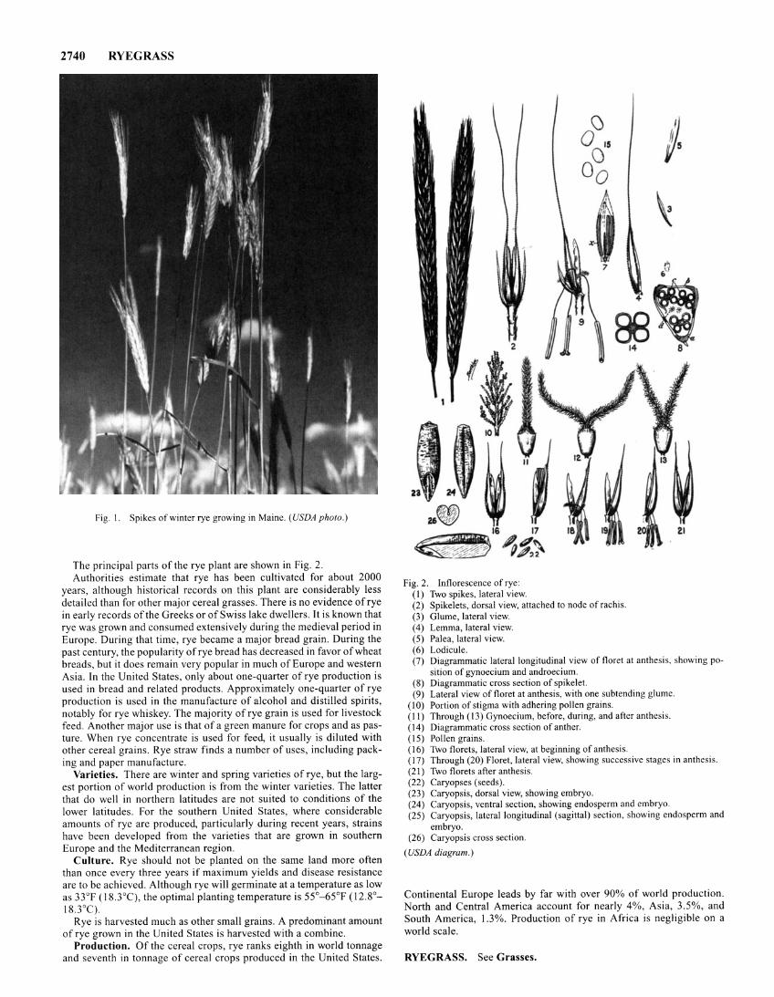
2740 RYEGRASS
Fig. l. Spikes of winter rye growing in Maine. (USDA photo.)
The principal parts of the rye plant are shown in Fig. 2. Authorities estimate that rye has been cultivated for about 2000
years, although historical records on this plant are considerably less detailed than for other major cereal grasses. There is no evidence of rye in early records of the Greeks or of Swiss lake dwellers. It is known that rye was grown and consumed extensively during the medieval period in Europe. During that time, rye became a major bread grain. During the past century, the popularity of rye bread has decreased in favor of wheat breads, but it does remain very popular in much of Europe and western Asia. In the United States, only about one-quarter of rye production is used in bread and related products. Approximately one-quarter of rye production is used in the manufacture of alcohol and distilled spirits, notably for rye whiskey. The majority of rye grain is used for livestock feed. Another major use is that of a green manure for crops and as pasture. When rye concentrate is used for feed, it usually is diluted with other cereal grains. Rye straw finds a number of uses, including packing and paper manufacture.
Varieties. There are winter and spring varieties of rye, but the largest portion of world production is from the winter varieties. The latter that do well in northern latitudes are not suited to conditions of the lower latitudes. For the southern United States, where considerable amounts of rye are produced, particularly during recent years, strains have been developed from the varieties that are grown in southern Europe and the Mediterranean region.
Culture. Rye should not be planted on the same land more often than once every three years if maximum yields and disease resistance are to be achieved. Although rye will germinate at a temperature as low as 33°F ( 18.3°C}, the optimal planting temperature is 55°- 65°F (12.8°-18.30C).
Rye is harvested much as other small grains. A predominant amount of rye grown in the United States is harvested with a combine.
Production. Of the cereal crops, rye ranks eighth in world tonnage and seventh in tonnage of cereal crops produced in the United States.
,aS, 14 8
Fig. 2. Inflorescence of rye: (I) Two spikes, lateral view. (2) Spikelets, dorsal view, attached to node of rachis. (3) Glume, lateral view. (4) Lemma, lateral view. (5) Palea, lateral view. ( 6) Lodicule. (7) Diagrammatic lateral longitudinal view of floret at anthesis, showing po
sition of gynoecium and androecium. (8) Diagrammatic cross section of spikelet. (9) Lateral view of floret at anthesis, with one subtending glume.
(I 0) Portion of stigma with adhering pollen grains. (II) Through (13) Gynoecium, before, during, and after anthesis. ( 14) Diagrammatic cross section of anther. ( 15) Pollen grains. ( 16) Two florets, lateral view, at beginning of anthesis. (17) Through (20) Floret, lateral view, showing successive stages in anthesis. (21) Two florets after an thesis. (22) Caryopses (seeds). (23) Caryopsis, dorsal view, showing embryo. (24) Caryopsis, ventral section, showing endosperm and embryo. (25) Caryopsis, lateral longitudinal (sagittal) section, showing endosperm and
embryo. (26) Caryopsis cross section.
(USDA diagram.)
Continental Europe leads by far with over 90% of world production. North and Central America account for nearly 4%, Asia, 3.5%, and South America, 1.3%. Production of rye in Africa is negligible on a world scale.
RYEGRASS. See Grasses.
Related Documents