RA100TNR-IEN083510 | 98-0018210 | Version 1.0 EN System Monitoring RA100T-NR Installation Guide

RA100TNR-IEN083510
Mar 16, 2016
http://download.sma.de/smaprosa/dateien/9330/RA100TNR-IEN083510.pdf
Welcome message from author
This document is posted to help you gain knowledge. Please leave a comment to let me know what you think about it! Share it to your friends and learn new things together.
Transcript

RA100TNR-IEN083510 | 98-0018210 | Version 1.0 EN
System MonitoringRA100T-NR Installation Guide


SMA Solar Technology AG Table of Contents
Installation Guide RA100TNR-IEN083510 3
Table of Contents1 Notes on this Manual. . . . . . . . . . . . . . . . . . . . . . . . . . . . . . 51.1 Validity . . . . . . . . . . . . . . . . . . . . . . . . . . . . . . . . . . . . . . . . . . . . 51.2 Target Group . . . . . . . . . . . . . . . . . . . . . . . . . . . . . . . . . . . . . . . 51.3 Symbols Used . . . . . . . . . . . . . . . . . . . . . . . . . . . . . . . . . . . . . . . 52 Safety . . . . . . . . . . . . . . . . . . . . . . . . . . . . . . . . . . . . . . . . . . 62.1 Appropriate Usage. . . . . . . . . . . . . . . . . . . . . . . . . . . . . . . . . . . 62.2 Safety Instructions . . . . . . . . . . . . . . . . . . . . . . . . . . . . . . . . . . . . 63 Unpacking. . . . . . . . . . . . . . . . . . . . . . . . . . . . . . . . . . . . . . . 73.1 Scope of delivery . . . . . . . . . . . . . . . . . . . . . . . . . . . . . . . . . . . . 73.2 Identifying the Irradiation and Temperature Sensor . . . . . . . . . . 74 Assembly and Electrical Connection. . . . . . . . . . . . . . . . . . 84.1 Cabling Recommendations . . . . . . . . . . . . . . . . . . . . . . . . . . . . . 84.2 Selecting the Mounting Location. . . . . . . . . . . . . . . . . . . . . . . . . 94.3 Mounting the Irradiation and Temperature Sensor . . . . . . . . . . . 94.4 Connection Overview . . . . . . . . . . . . . . . . . . . . . . . . . . . . . . . . . 94.5 Connecting the Sensor to the Sunny Boy Control Plus . . . . . . . 104.5.1 Irradiation Sensor . . . . . . . . . . . . . . . . . . . . . . . . . . . . . . . . . . . . . . . . . . . . . 104.5.2 Temperature sensor. . . . . . . . . . . . . . . . . . . . . . . . . . . . . . . . . . . . . . . . . . . . 104.6 Connecting the Sensor to the Sunny Central . . . . . . . . . . . . . . 114.6.1 Irradiation Sensor . . . . . . . . . . . . . . . . . . . . . . . . . . . . . . . . . . . . . . . . . . . . . 114.6.2 Temperature sensor. . . . . . . . . . . . . . . . . . . . . . . . . . . . . . . . . . . . . . . . . . . . 12
5 Configuration . . . . . . . . . . . . . . . . . . . . . . . . . . . . . . . . . . . 135.1 Irradiation Sensor . . . . . . . . . . . . . . . . . . . . . . . . . . . . . . . . . . . 135.1.1 Configuring the Sensor with the Sunny Boy Control Plus . . . . . . . . . . . . . . . 135.1.2 Configuring the Sensor with the Sunny Central Control . . . . . . . . . . . . . . . . 13

Table of Contents SMA Solar Technology AG
4 RA100TNR-IEN083510 Installation Guide
5.2 Temperature Sensor for the Temperature Compensation . . . . . 145.2.1 Configuring the Sensor with the Sunny Boy Control Plus . . . . . . . . . . . . . . . 145.2.2 Configuring the Sensor with the Sunny Central Control . . . . . . . . . . . . . . . . 14
6 Decommissioning . . . . . . . . . . . . . . . . . . . . . . . . . . . . . . . . 156.1 Dismounting the Sensor. . . . . . . . . . . . . . . . . . . . . . . . . . . . . . . 156.2 Disposal . . . . . . . . . . . . . . . . . . . . . . . . . . . . . . . . . . . . . . . . . . 157 Technical Data . . . . . . . . . . . . . . . . . . . . . . . . . . . . . . . . . . 168 Accessories . . . . . . . . . . . . . . . . . . . . . . . . . . . . . . . . . . . . . 179 Contact . . . . . . . . . . . . . . . . . . . . . . . . . . . . . . . . . . . . . . . . 18

SMA Solar Technology AG Notes on this Manual
Installation Guide RA100TNR-IEN083510 5
1 Notes on this ManualThis manual describes the installation and commissioning of the irradiation and temperature sensor. Store this manual where it will be accessible at all times.
1.1 ValidityThis manual is valid for the RA100T upgrade kit.
1.2 Target GroupThis manual is for qualified personnel.
1.3 Symbols UsedThe following types of warnings and general information appear in this document as described below.
DANGER!
DANGER indicates a hazardous situation which, if not avoided, will result in death or serious injury.WARNING!
WARNING indicates a hazardous situation which, if not avoided, could result in death or serious injury.CAUTION!
CAUTION indicates a hazardous situation which, if not avoided, could result in minor or moderate injury!NOTICE!
ATTENTION indicates a situation that can result in property damage if not avoided.Information"Information" provides tips that are valuable for the optimal operation of your product.

Safety SMA Solar Technology AG
6 RA100TNR-IEN083510 Installation Guide
2 Safety2.1 Appropriate UsageThe RA100T is a modular irradiation and temperature sensor. The sensor consists of a monocrystalline silicon solar cell and an integrated temperature sensor module PT100. The irradiation sensor is calibrated to 25 °C; the measuring range can be found on the sensor's type label. The measuring range of the temperature sensor is between -30 °C and +50 °C.In order to process the ambient data, the sensors must be connected to the Sunny Boy Control Plus or the Sunny Central Control.The sensor is only suitable for use with original SMA accessories or with accessories recommended by SMA Solar Technology AG.Appropriate usage also includes observing all further documentation relating to this device and its components.
2.2 Safety InstructionsNOTICE!Damage to the sensor as a result of incorrect connection to the Sunny Boy Control Plus or Sunny Central Control.The Sunny Boy Control installation guide and the wiring diagram provided must be used for establishing the electrical connections and connectors!
NOTICE!Destruction of the PV system by a lightning strike.
All devices installed on a rooftop must be integrated in the existing lightning protection of the PV system.Overvoltage protectorProtect your PV system components against overvoltage from outside by connecting the sensors to an overvoltage protector. For using the sensors with the Sunny Central Control, the corresponding overvoltage protectors can be ordered from Sunny Central as an option.

SMA Solar Technology AG Unpacking
Installation Guide RA100TNR-IEN083510 7
3 Unpacking3.1 Scope of delivery
3.2 Identifying the Irradiation and Temperature SensorYou can identify the sensor using the type plate. The type plate can be found on the back of the enclosure.
A 1 RA100T (irradiation and temperature sensor with 5 m cable)
A

Assembly and Electrical Connection SMA Solar Technology AG
8 RA100TNR-IEN083510 Installation Guide
4 Assembly and Electrical ConnectionThe irradiation and temperature sensor RA100T can be connected to the Sunny Boy Control Plus or the Sunny Central. Observe the prefabricated cable length of 5 m. The cable must not be shortened. If the length of the cable is insufficient, you can extend it using a junction box, for example. The temperature sensor can then be connected in either a 2- or 4-cable system.
4.1 Cabling RecommendationsThe cable length and quality have an effect on the signal quality. To achieve a good quality signal, observe the following instructions regarding cabling:OutdoorsFor the outdoors, use a communication cable with the following key properties.
• Cross-section: min. 6 x 0.25 mm2, min. 6 x AWG 24• UV-resistant
We recommend the following cable types:• UL-listed Lapp cable: UNITRONIC Li9Y11Y 8 x 0.25 mm2, order no.: 7038 868
2-cable systemWhen connecting the temperature sensor in a 2-cable system, the cable resistance is included in the measurement. This can lead to measuring inaccuracies depending on the cable length.For this reason, the 2-cable system should only be used with short cable lengths (max. 3 m) or where the level of measuring accuracy required is not as high. In order to increase the measuring accuracy, the use of a 4-cable system is recommended.4-cable systemTo offset measuring errors that occur due to cable resistance, connect the temperature sensor in a 4-cable system. With this type of connection, the current feed and voltage measurement are carried out by separate pair cables. The length of the cable must not exceed 30 m.Protect connection interfaces against weather effects.When extending the sensor cable, protect the connection interface against weather effects (e.g. using a junction box or terminal box).

SMA Solar Technology AG Assembly and Electrical Connection
Installation Guide RA100TNR-IEN083510 9
IndoorsIf you protect the cable from UV radiation outdoors by means of a suitable cable channel, you can also use a non-UV-resistant (indoor) cable with the basic properties mentioned above.We recommend the following cable types:
• Lapp cable: Unitronic LiYY 7 x 0.25 mm2, order no.: 0028 307• UL-listed Lapp cable: UNITRONIC LiYY UL/CSA 7 x AWG22/7, order no.: 0022 607• Helukabel: TRONIC LiYY 6 x 0.25 mm2, order no.: 18033
4.2 Selecting the Mounting LocationConsider the following points during the selection of a mounting location:
• The sensor is suitable for outside mounting.• Select a position that is as level with the solar cells as possible and not shaded during the
daytime.• Observe the prefabricated cable length of 5 m; the cable must not be shortened.
4.3 Mounting the Irradiation and Temperature Sensor1. Connect the irradiation and temperature sensor to the bracket using the nuts recessed in the
frame.2. Lay the connection cable.☑ The irradiation and temperature sensor is fully mounted.
4.4 Connection OverviewThe sensor's wire assignment is as follows:
Wire color AssignmentGreen Irradiation sensor +White Irradiation sensor -Yellow Temperature sensor PT100
(The sensor's wire assignment can be defined as desired. However, when using a 4-cable system, the connection assignment should be observed)
Brown

Assembly and Electrical Connection SMA Solar Technology AG
10 RA100TNR-IEN083510 Installation Guide
4.5 Connecting the Sensor to the Sunny Boy Control PlusThe sensor is connected to the analog input port (ANALOG IN) of the Sunny Boy Control Plus.
4.5.1 Irradiation SensorThe irradiation sensor is connected to an available analog input port (ANALOG IN) of the Sunny Boy Control Plus.
4.5.2 Temperature sensorThe temperature sensor is connected using a 2- or 4-cable system to the analog input port (ANALOG IN) of the Sunny Boy Control Plus.4-cable systemThe analog input ports AIN-7 and AIN-8 are fitted with PT100 resistors for use with a 4-cable system. The supply currents required for this are provided by the Sunny Boy Control Plus. The temperature sensor's connection wires are duplicated in the direct vicinity of the sensor. Thus a total of 6 wires are required (2 wires for the irradiation sensor and 4 wires for the temperature sensor).
or
Protect connection interfaces against weather effects.When extending the sensor cable, protect the connection interface against weather effects (e.g. using a junction box or terminal box). Connection of sensors using a connection terminal blockTo connect to the Sunny Boy Control Plus, use the 25-pin connection terminal block (see section 8 "Accessories" (page 17)).
Connection of the irradiation sensorGreen (irradiation sensor +) PIN 1 (AIN-1) or
PIN 3 (AIN-2) or PIN 5 (AIN-3) to PIN 8 (AIN-6)
White (irradiation sensor -) PIN 14 (AGND) to PIN 19 (AGND) or PIN 24 (AGND)
Connection of temperature sensor PT100 to "AIN-7" in a 4-cable systemOriginal wire, yellow PIN 11 (PT100-I1+)Duplicated wire, yellow PIN 9 (AIN-7+)Duplicated wire, brown PIN 20 (AIN-7-)Original wire, brown PIN 22 (PT100-I1-)
Connection of temperature sensor PT100 to "AIN-8" in a 4-cable systemOriginal wire, yellow PIN 12 (PT100-I2+)Duplicated wire, yellow PIN 10 (AIN-8+)

SMA Solar Technology AG Assembly and Electrical Connection
Installation Guide RA100TNR-IEN083510 11
2-cable system
or
4.6 Connecting the Sensor to the Sunny CentralAt the Sunny Central, the sensor is connected to the Sunny Central Control using the terminal strips Z5-X5.
4.6.1 Irradiation SensorIn this case, an analog input is used as the voltage input. To do so, the positive pole of the reference cell is connected to terminal 5 or 7 and the negative pole of the reference cell is connected to terminal 6 or 8.
or
Duplicated wire, brown PIN 21 (AIN-8-)Originalader, Braun PIN 23 (PT100-I2-)
Connection of temperature sensor PT100 to "AIN-7" in a 2-cable systemYellow Bridge PIN 9 (AIN-7+) with PIN 11 (PT100-I1+) Brown Bridge PIN 20 (AIN-7-) with PIN 22 (PT100-I1-)
Connection of temperature sensor PT100 to "AIN-8" in a 2-cable systemYellow Bridge PIN 10 (AIN-8+) with PIN 12 (PT100-I2+) Brown Bridge PIN 21 (AIN-8-) with PIN 23 (PT100-I2-)
Protect connection interfaces against weather effects.When extending the sensor cable, protect the connection interface against weather effects (e.g. using a junction box or terminal box). Realizing the electrical connectionThe wiring diagram provided must be used for establishing the electrical connections and connectors.
Connection of irradiation sensor to "=Z5-X5"Green (irradiation sensor +) Terminal 5White (irradiation sensor -) Terminal 6
Connection of irradiation sensor to "=Z5-X5"Green (irradiation sensor +) Terminal 7White (irradiation sensor -) Terminal 8
Connection of temperature sensor PT100 to "AIN-8" in a 4-cable system

Assembly and Electrical Connection SMA Solar Technology AG
12 RA100TNR-IEN083510 Installation Guide
4.6.2 Temperature sensorThe temperature sensor is connected using a 2 or 4-cable system.4-cable systemThe temperature sensor's connection wires are duplicated in the direct vicinity of the sensor. Thus a total of 6 wires are required (2 wires for the irradiation sensor and 4 wires for the temperature sensor). The connection is established without using bridges on the terminal strip in accordance with the following connection plan:
2-cable systemIf measuring is carried out using a 2-cable system, the connection is established in accordance with the following connection plan:
or
or
Connection of temperature sensor PT100 to "=Z5-X5" in a 4-cable systemOriginal wire, yellow Terminal 1Duplicated wire, yellow Terminal 2Original wire, brown Terminal 3Duplicated wire, brown Terminal 4
Connection of temperature sensor PT100 to "=Z5-X5" in a 2-cable systemYellow Bridge terminal 1 with terminal 2Brown Bridge terminal 3 with terminal 4
Connection of temperature sensor PT100 to "=Z5-X5" in a 2-cable systemYellow Terminal 5Brown Terminal 6
Connection of temperature sensor PT100 to "=Z5-X5" in a 2-cable systemYellow Terminal 7Brown Terminal 8
SMA Solar Technology AG Configuration
Installation Guide RA100TNR-IEN083510 13
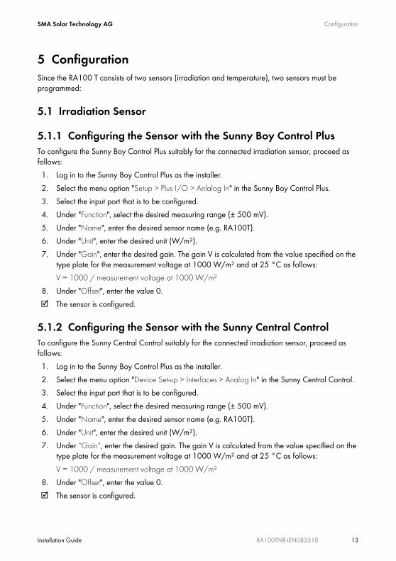
5 ConfigurationSince the RA100 T consists of two sensors (irradiation and temperature), two sensors must be programmed:
5.1 Irradiation Sensor
5.1.1 Configuring the Sensor with the Sunny Boy Control PlusTo configure the Sunny Boy Control Plus suitably for the connected irradiation sensor, proceed as follows:1. Log in to the Sunny Boy Control Plus as the installer.2. Select the menu option "Setup > Plus I/O > Anlalog In" in the Sunny Boy Control Plus.3. Select the input port that is to be configured.4. Under "Function", select the desired measuring range (± 500 mV).5. Under "Name", enter the desired sensor name (e.g. RA100T).6. Under "Unit", enter the desired unit (W/m²). 7. Under "Gain", enter the desired gain. The gain V is calculated from the value specified on the
type plate for the measurement voltage at 1000 W/m² and at 25 °C as follows:V = 1000 / measurement voltage at 1000 W/m²
8. Under "Offset", enter the value 0.☑ The sensor is configured.
5.1.2 Configuring the Sensor with the Sunny Central ControlTo configure the Sunny Central Control suitably for the connected irradiation sensor, proceed as follows:1. Log in to the Sunny Boy Control Plus as the installer.2. Select the menu option "Device Set-up > Interfaces > Analog In" in the Sunny Central Control.3. Select the input port that is to be configured.4. Under "Function", select the desired measuring range (± 500 mV).5. Under "Name", enter the desired sensor name (e.g. RA100T).6. Under "Unit", enter the desired unit (W/m²). 7. Under "Gain", enter the desired gain. The gain V is calculated from the value specified on the
type plate for the measurement voltage at 1000 W/m² and at 25 °C as follows:V = 1000 / measurement voltage at 1000 W/m²
8. Under "Offset", enter the value 0.☑ The sensor is configured.
Configuration SMA Solar Technology AG
14 RA100TNR-IEN083510 Installation Guide
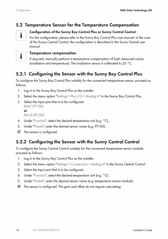
5.2 Temperature Sensor for the Temperature Compensation
5.2.1 Configuring the Sensor with the Sunny Boy Control PlusTo configure the Sunny Boy Control Plus suitably for the connected temperature sensor, proceed as follows:1. Log in to the Sunny Boy Control Plus as the installer.2. Select the menu option "Settings > Plus I/O > Analog In" in the Sunny Boy Control Plus.3. Select the input port that is to be configured:
AIN7 (PT100) or AIN 8 (PT100)
4. Under "Function", select the desired temperature unit (e.g. °C).5. Under "Name", enter the desired sensor name (e.g. PT100).☑ The sensor is configured.
5.2.2 Configuring the Sensor with the Sunny Central ControlTo configure the Sunny Central Control suitably for the connected temperature sensor module, proceed as follows:1. Log in to the Sunny Boy Control Plus as the installer.2. Select the menu option "Settings > Connections > Analog In" in the Sunny Central Control.3. Select the input port that is to be configured.4. Under "Function", select the desired temperature unit (e.g. °C).5. Under "Name", enter the desired sensor name (e.g. temperature sensor module).☑ The sensor is configured. The gain and offset do not require calculating.
Configuration of the Sunny Boy Control Plus or Sunny Central ControlFor the configuration, please refer to the Sunny Boy Control Plus user manual. In the case of the Sunny Central Control, the configuration is described in the Sunny Central user manual.Temperature compensationIf required, manually perform a temperature compensation of both measured values (irradiation and temperature). The irradiation sensor is calibrated to 25 °C.
SMA Solar Technology AG Decommissioning
Installation Guide RA100TNR-IEN083510 15
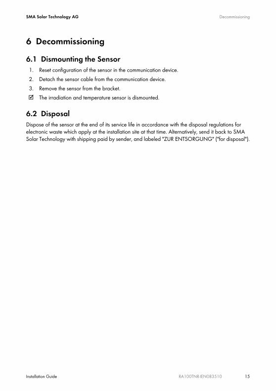
6 Decommissioning6.1 Dismounting the Sensor1. Reset configuration of the sensor in the communication device. 2. Detach the sensor cable from the communication device.3. Remove the sensor from the bracket.☑ The irradiation and temperature sensor is dismounted.
6.2 DisposalDispose of the sensor at the end of its service life in accordance with the disposal regulations for electronic waste which apply at the installation site at that time. Alternatively, send it back to SMA Solar Technology with shipping paid by sender, and labeled "ZUR ENTSORGUNG" ("for disposal").
Technical Data SMA Solar Technology AG
16 RA100TNR-IEN083510 Installation Guide
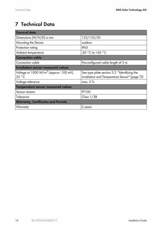
7 Technical DataGeneral dataDimensions (W/H/D) in mm 122/122/20Mounting the Device outdoorProtection rating IP65Ambient temperature -30 °C to +50 °CConnection cableConnection cable Pre-configured cable length of 5 m.Irradiation sensor measured valuesVoltage at 1000 W/m2 (approx. 100 mV), 25 °C
See type plate section 3.2 "Identifying the Irradiation and Temperature Sensor" (page 7))
Voltage tolerance max. 5 %Temperature sensor measured valuesSensor resistor PT100Tolerance Class 1/3BWarranty, Certificates and PermitsWarranty 2 years

SMA Solar Technology AG Accessories
Installation Guide RA100TNR-IEN083510 17
8 AccessoriesDescription SMA order number
Analog IN connection terminal block
25-pin, D-Sub plug for Sunny Boy Control Plus (incl. 1:1 cable, D-Sub 25-pin, bushing/plug, length 0.5 m
SBCOP-ANA-KIT
Contact SMA Solar Technology AG
18 RA100TNR-IEN083510 Installation Guide
9 ContactIf you have technical problems concerning our products, contact our Service Line. We need the following information in order to provide you with the necessary assistance:
• Model of the sensor• Communication device• Measured values
SMA Solar Technology AGSonnenallee 134266 Niestetal, Germanywww.SMA.de
Serviceline Inverters: +49 561 9522 1499Communication: +49 561 9522 2499Fax: +49 561 9522 4699E-Mail: [email protected]
Sunny CentralSMA Solar Technology AG Sonnenallee 134266 Niestetal, GermanyTel. +49 561 9522 299Fax +49 561 9522 3299 [email protected] www.SMA.de

SMA Solar Technology AG Legal Restrictions
Installation Guide RA100TNR-IEN083510 19
The information contained in this document is the property of SMA Solar Technology AG. Publishing its content, either partially or in full, requires the written permission of SMA Solar Technology AG. Any internal company copying of the document for the purposes of evaluating the product or its correct implementation is allowed and does not require permission.
Exclusion of liabilityThe general terms and conditions of delivery of SMA Solar Technology AG shall apply.The content of these documents is continually checked and amended, where necessary. However, discrepancies cannot be excluded. No guarantee is made for the completeness of these documents. The latest version is available online at www.SMA.de or from the usual sales channels.Guarantee or liability claims for damages of any kind are excluded if they are caused by one or more of the following: • Damages during transportation• Improper or inappropriate use of the product• Operating the product in an unintended environment• Operating the product whilst ignoring relevant, statutory safety regulations in the deployment location• Ignoring safety warnings and instructions contained in all documents relevant to the product• Operating the product under incorrect safety or protection conditions• Altering the product or supplied software without authority• The product malfunctions due to operating attached or neighboring devices beyond statutory limit values• In case of unforeseen calamity or force majeureThe use of supplied software produced by SMA Solar Technology AG is subject to the following conditions:• SMA Solar Technology AG rejects any liability for direct or indirect damages arising from the use of software developed by
SMA Solar Technology AG. This also applies to the provision or non-provision of support activities.• Supplied software not developed by SMA Solar Technology AG is subject to the respective licensing and liability agreements
of the manufacturer.
SMA Factory WarrantyThe current guarantee conditions come enclosed with your device. These are also available online at www.SMA.de and can be downloaded or are available on paper from the usual sales channels if required.
TrademarksAll trademarks are recognized even if these are not marked separately. Missing designations do not mean that a product or brand is not a registered trademark.The Bluetooth® word mark and logos are registered trademarks owned by Bluetooth SIG, Inc. and any use of such marks by SMA Solar Technology is under license.SMA Solar Technology AGSonnenallee 134266 NiestetalGermanyTel. +49 561 9522-0Fax +49 561 9522-100www.SMA.deE-Mail: [email protected]© 2004 to 2009 SMA Solar Technology AG. All rights reserved

SMA Solar Technology AG
Sonnenallee 1
34266 Niestetal, Germany
Tel.: +49 561 9522 4000
Fax: +49 561 9522 4040
E-Mail: [email protected]
Freecall: 0800 SUNNYBOY
Freecall: 0800 78669269
www.SMA.de