1 G5 rotary servo motors R88M-K@, R88M-KH@ G5 Rotary Servo Motors Servo family for accurate motion control. Power range extended up to 15 kW. • Standard and high inertia servo motor models • Peak torque 300% of rated torque during 3 seconds or more depending on model • High resolution serial encoder provided by 20 bits encoder • IP67 protection in all models • Ultra-light and compact size motor • Low speed ripple and low torque ripple due to low torque cogging • Various shaft, brake and seal options Ratings • 230 VAC from 50 W to 1.5 kW (rated torque from 0.16 to 8.59 Nm) • 400 VAC from 400 W to 15 kW (rated torque from 1.91 Nm to 95.5 Nm) System configuration (Refer to servo drive chapter) Encoder cable Power cable 3000 rpm (750 W to 5 kW) 2000 rpm (400 W to 5 kW) 1000 rpm (900 W to 3 kW) Power cable Encoder cable 3000 rpm (50 W to 750 W) 1500 rpm (7.5 kW to 15 kW) 1000 rpm (4.5 kW to 6 kW) 2000 rpm (1 kW to 5 kW) 1500 rpm (7.5 kW) Encoder cable Power cable Servo drive options G5 servo drives EtherCAT and Analogue/pulse models Standard servo motors High inertia servo motors Power cable Encoder cable 3000 rpm (200 W to 750 W)

Welcome message from author
This document is posted to help you gain knowledge. Please leave a comment to let me know what you think about it! Share it to your friends and learn new things together.
Transcript
1G5 rotary servo motors
R88M-K@, R88M-KH@
G5 Rotary Servo MotorsServo family for accurate motion control. Power range extended up to 15 kW.
• Standard and high inertia servo motor models• Peak torque 300% of rated torque during 3 seconds
or more depending on model• High resolution serial encoder provided by 20 bits
encoder• IP67 protection in all models• Ultra-light and compact size motor• Low speed ripple and low torque ripple due to low
torque cogging• Various shaft, brake and seal optionsRatings
• 230 VAC from 50 W to 1.5 kW(rated torque from 0.16 to 8.59 Nm)
• 400 VAC from 400 W to 15 kW(rated torque from 1.91 Nm to 95.5 Nm)
System configuration
(Refer to servo drive chapter)
Encoder cable
Power cable 3000 rpm (750 W to 5 kW)2000 rpm (400 W to 5 kW)1000 rpm (900 W to 3 kW)
Power cable
Encoder cable3000 rpm (50 W to 750 W)
1500 rpm (7.5 kW to 15 kW)1000 rpm (4.5 kW to 6 kW)
2000 rpm (1 kW to 5 kW)
1500 rpm (7.5 kW)
Encoder cable
Power cable
Servo drive options
ADR
G5 servo drives EtherCAT and
Analogue/pulse models
Standard servo motors
High inertia servo motorsPower cable
Encoder cable3000 rpm (200 W to 750 W)
2 AC servo systems
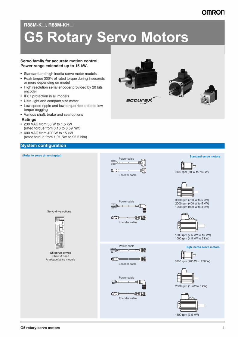
Standard servo motors
High inertia servo motors
Note: 1. For servo motor and cables part numbers refer to ordering information at the end of this chapter2. Refer to the servo drive chapter for drive options selection and detailed specifications
Servo motor / servo drive combination
G5 rotary servo motor G5 rotary servo drive modelsVoltage Speed Rated torque Capacity Model EtherCAT Analog/pulse 230 V 3000 min-1 0.16 Nm 50 W R88M-K05030(H/T)-@ R88D-KN01H-ECT R88D-KT01H
0.32 Nm 100 W R88M-K10030(H/T)-@ R88D-KN01H-ECT R88D-KT01H0.64 Nm 200 W R88M-K20030(H/T)-@ R88D-KN02H-ECT R88D-KT02H1.3 Nm 400 W R88M-K40030(H/T)-@ R88D-KN04H-ECT R88D-KT04H2.4 Nm 750 W R88M-K75030(H/T)-@ R88D-KN08H-ECT R88D-KT08H
230 V (1 kW to 1.5 kW)
400 V (400 W to 5 kW)
7.5 KW to 15 kW
3.18 Nm 1000 W R88M-K1K030(H/T)-@ R88D-KN15H-ECT R88D-KT15H4.77 Nm 1500 W R88M-K1K530(H/T)-@ R88D-KN15H-ECT R88D-KT15H
400 V 2.39 Nm 750 W R88M-K75030(F/C)-@ R88D-KN10F-ECT R88D-KT10F3.18 Nm 1000 W R88M-K1K030(F/C)-@ R88D-KN15F-ECT R88D-KT15F4.77 Nm 1500 W R88M-K1K530(F/C)-@ R88D-KN15F-ECT R88D-KT15F6.37 Nm 2000 W R88M-K2K030(F/C)-@ R88D-KN20F-ECT R88D-KT20F9.55 Nm 3000 W R88M-K3K030(F/C)-@ R88D-KN30F-ECT R88D-KT30F12.7 Nm 4000 W R88M-K4K030(F/C)-@ R88D-KN50F-ECT R88D-KT50F15.9 Nm 5000 W R88M-K5K030(F/C)-@ R88D-KN50F-ECT R88D-KT50F
230 V 2000 min-1 4.77 Nm 1000 W R88M-K1K020(H/T)-@ R88D-KN10H-ECT R88D-KT10H7.16 Nm 1500 W R88M-K1K520(H/T)-@ R88D-KN15H-ECT R88D-KT15H
400 V 1.91 Nm 400 W R88M-K40020(F/C)-@ R88D-KN06F-ECT R88D-KT06F2.86 Nm 600 W R88M-K60020(F/C)-@ R88D-KN06F-ECT R88D-KT06F4.77 Nm 1000 W R88M-K1K020(F/C)-@ R88D-KN10F-ECT R88D-KT10F7.16 Nm 1500 W R88M-K1K520(F/C)-@ R88D-KN15F-ECT R88D-KT15F9.55 Nm 2000 W R88M-K2K020(F/C)-@ R88D-KN20F-ECT R88D-KT20F14.3 Nm 3000 W R88M-K3K020(F/C)-@ R88D-KN30F-ECT R88D-KT30F19.1 Nm 4000 W R88M-K4K020(F/C)-@ R88D-KN50F-ECT R88D-KT50F23.9 Nm 5000 W R88M-K5K020(F/C)-@ R88D-KN50F-ECT R88D-KT50F
400 V 1500 min-1 47.8 Nm 7500 W R88M-K7K515C-@ R88D-KN75F-ECT R88D-KT75F70.0 Nm 11000 W R88M-K11K015C-@ R88D-KN150F-ECT R88D-KT150F95.5 Nm 15000 W R88M-K15K015C-@ R88D-KN150F-ECT R88D-KT150F
230 V 1000 min-1 8.59 Nm 900 W R88M-K90010(H/T)-@ R88D-KN15H-ECT R88D-KT15H400 V 8.59 Nm 900 W R88M-K90010(F/C)-@ R88D-KN15F-ECT R88D-KT15F
19.1 Nm 2000 W R88M-K2K010(F/C)-@ R88D-KN30F-ECT R88D-KT30F28.7 Nm 3000 W R88M-K3K010(F/C)-@ R88D-KN50F-ECT R88D-KT50F43.0 Nm 4500 W R88M-K4K510C-@ R88D-KN50F-ECT R88D-KT50F57.3 Nm 6000 W R88M-K6K010C-@ R88D-KN75F-ECT R88D-KT75F
G5 rotary servo motor G5 rotary servo drive modelsVoltage Speed Rated torque Capacity Model EtherCAT Analog/pulse 230 V 3000 min-1 0.64 Nm 200 W R88M-KH20030(H/T)-@ R88D-KN02H-ECT R88D-KT02H
1.3 Nm 400 W R88M-KH40030(H/T)-@ R88D-KN04H-ECT R88D-KT04H
2.4 Nm 750 W R88M-KH75030(H/T)-@ R88D-KN08H-ECT R88D-KT08H
1 kW to 5 kW
7.5 KW
400 V 2000 min-1 4.77 Nm 1000 W R88M-KH1K020(F/C)-@ R88D-KN10F-ECT R88D-KT10F
7.16 Nm 1500 W R88M-KH1K520(F/C)-@ R88D-KN15F-ECT R88D-KT15F
9.55 Nm 2000 W R88M-KH2K020(F/C)-@ R88D-KN20F-ECT R88D-KT20F
14.3 Nm 3000 W R88M-KH3K020(F/C)-@ R88D-KN30F-ECT R88D-KT30F
19.1 Nm 4000 W R88M-KH4K020(F/C)-@ R88D-KN50F-ECT R88D-KT50F
23.9 Nm 5000 W R88M-KH5K020(F/C)-@ R88D-KN50F-ECT R88D-KT50F
1500 min-1 47.8 Nm 7500 W R88M-KH7K515C-@ R88D-KN75F-ECT R88D-KT75F
G5 rotary servo motors 3
Standard servo motors
High inertia servo motors
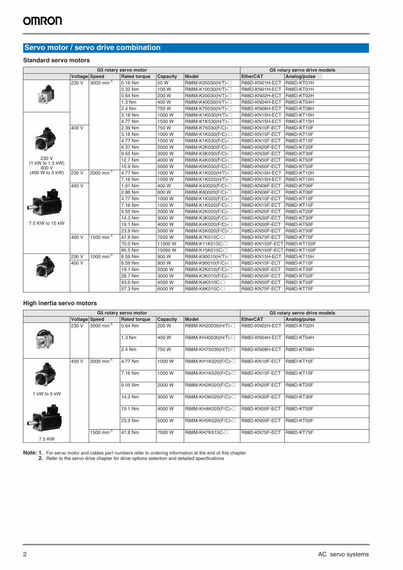
Servo motor type designation
50 W100 W200 W400 W
050100200400
900 W900750 W750
G5 rotary servomotor
Capacity
Shaft end specifications
Voltage and encoder specifications H: 230 V and 20-bit incremental encoder
T: 230 V and 17-bit absolute encoder
F: 400 V and 20-bit incremental encoder
C: 400 V and 17-bit absolute encoder
R88M-K05030H-BOS2
1K0 1 kW1K5 1.5 kW
Rated Speed (r/min)10001500 20003000
10152030
Straigth shaft, no keyBlankS2 Straigth, key, tapped (standard)
Oil seal specificationsNo oil sealBlank
O Oil seal
Brake specificationsNo brakeBlank
B Brake
600 W600
2K03K04K04K5
2 kW3 kW4 kW
4.5 kW5K06K07K511K015K0
4.5 kW5 kW6 kW
7.5 kW11 kW15 kW
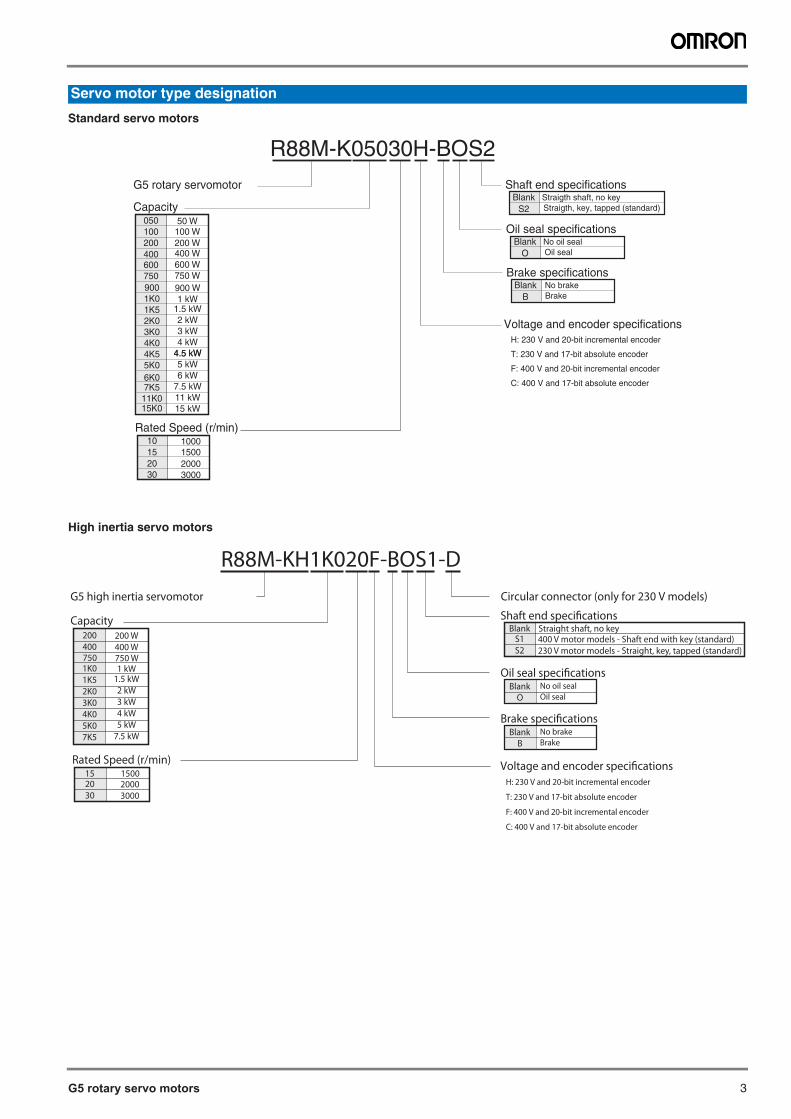
G5 high inertia servomotor
Capacity
Brake specifications
Voltage and encoder specifications H: 230 V and 20-bit incremental encoder
T: 230 V and 17-bit absolute encoder
F: 400 V and 20-bit incremental encoder
C: 400 V and 17-bit absolute encoder
R88M-KH1K020F-BOS1-D
1K0 1 kW1K5 1.5 kW
Rated Speed (r/min)1500 2000
1520
Blank No brake
2K03K04K0
2 kW3 kW4 kW
5K07K5
5 kW7.5 kW
B Brake
Circular connector (only for 230 V models)
750 750 W400 400 W200 200 W
300030
Oil seal specificationsBlank No oil seal
O Oil seal
Shaft end specificationsStraight shaft, no key400 V motor models - Shaft end with key (standard)
BlankS1
230 V motor models - Straight, key, tapped (standard)S2
4 AC servo systems
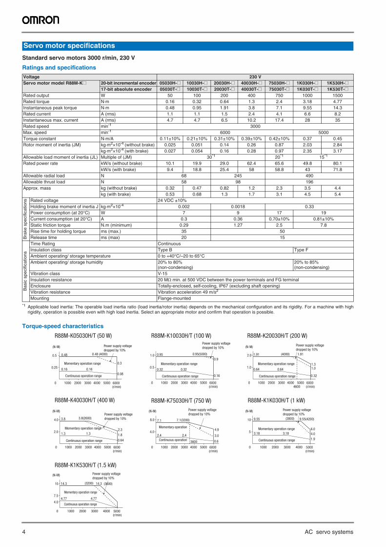
Standard servo motors 3000 r/min, 230 V
Ratings and specifications
Torque-speed characteristics
Servo motor specifications
Voltage 230 VServo motor model R88M-K@ 20-bit incremental encoder 05030H-@ 10030H-@ 20030H-@ 40030H-@ 75030H-@ 1K030H-@ 1K530H-@
17-bit absolute encoder 05030T-@ 10030T-@ 20030T-@ 40030T-@ 75030T-@ 1K030T-@ 1K530T-@Rated output W 50 100 200 400 750 1000 1500Rated torque N·m 0.16 0.32 0.64 1.3 2.4 3.18 4.77Instantaneous peak torque N·m 0.48 0.95 1.91 3.8 7.1 9.55 14.3Rated current A (rms) 1.1 1.1 1.5 2.4 4.1 6.6 8.2Instantaneous max. current A (rms) 4.7 4.7 6.5 10.2 17.4 28 35Rated speed min-1 3000Max. speed min-1 6000 5000Torque constant N·m/A 0.11±10% 0.21±10% 0.31±10% 0.39±10% 0.42±10% 0.37 0.45Rotor moment of inertia (JM) kg·m2×10-4 (without brake) 0.025 0.051 0.14 0.26 0.87 2.03 2.84
kg·m2×10-4 (with brake) 0.027 0.054 0.16 0.28 0.97 2.35 3.17Allowable load moment of inertia (JL) Multiple of (JM) 30*1
*1 Applicable load inertia: The operable load inertia ratio (load inertia/rotor inertia) depends on the mechanical configuration and its rigidity. For a machine with highrigidity, operation is possible even with high load inertia. Select an appropriate motor and confirm that operation is possible.
20*1 15*1
Rated power rate kW/s (without brake) 10.1 19.9 29.0 62.4 65.6 49.8 80.1kW/s (with brake) 9.4 18.8 25.4 58 58.8 43 71.8
Allowable radial load N 68 245 490Allowable thrust load N 58 98 196Approx. mass kg (without brake) 0.32 0.47 0.82 1.2 2.3 3.5 4.4
kg (with brake) 0.53 0.68 1.3 1.7 3.1 4.5 5.4
Bra
ke s
peci
ficat
ions Rated voltage 24 VDC ±10%
Holding brake moment of inertia J kg·m2×10-4 0.002 0.0018 0.33Power consumption (at 20°C) W 7 9 17 19Current consumption (at 20°C) A 0.3 0.36 0.70±10% 0.81±10%Static friction torque N.m (minimum) 0.29 1.27 2.5 7.8Rise time for holding torque ms (max.) 35 50Release time ms (max) 20 15
Bas
ic s
peci
ficat
ions
Time Rating ContinuousInsulation class Type B Type FAmbient operating/ storage temperature 0 to +40°C/–20 to 65°CAmbient operating/ storage humidity 20% to 80%
(non-condensing)20% to 85% (non-condensing)
Vibration class V-15Insulation resistance 20 M min. at 500 VDC between the power terminals and FG terminalEnclosure Totally-enclosed, self-cooling, IP67 (excluding shaft opening)Vibration resistance Vibration acceleration 49 m/s2
Mounting Flange-mounted
R88M-K05030H/T (50 W) R88M-K10030H/T (100 W) R88M-K20030H/T (200 W)
R88M-K40030H/T (400 W)
4.0
0 1000 2000 3000
3600
4000 6000 (r/min)
5000
8.0 7.1
4.9
3.0
7.1(3200)
2.4 2.4
Power supply voltage dropped by 10%
R88M-K75030H/T (750 W) R88M-K1K030H/T (1 kW)
7.5
4.0
0 1000 2000 3000 4000 5000 (r/min)
15 14.3 14.3
4.77 4.77
Momentary operation range
Continuous operation range
Power supply voltage dropped by 10%
R88M-K1K530H/T (1.5 kW)
0.25
0 1000 2000 3000 4000 6000 (r/min)
5000
0.5 0.48
0.16 0.16
0.48 (4000)
0.3
(N-M) (N-M)
(N-M)(N-M)(N-M)
(N-M)
Momentary operation range
Continuous operation range
Power supply voltagedropped by 10%
0.08
0.5
0 1000 2000 3000 4000 6000 (r/min)
5000
1.0 0.95
0.32 0.32
0.95(5000)
0.9
0.16
Power supply voltagedropped by 10%
Momentary operation range
Continuous operation range
1.0
0 1000 2000 3000 4000 6000 (r/min)
5000
2.0 1.91
0.64 0.64
1.91
1.3 1.0
0.32
(4000)
Momentary operation range
Continuous operation range
Power supply voltagedropped by 10%
4600
2.0
0 1000 2000 3000 4000 6000 (r/min)
5000
4.0 3.8
1.3 1.3 1.8
2.3
3.8(2600)
0.64
Momentary operation range
Continuous operation range
Power supply voltagedropped by 10%
0.6
5
0 1000 2000 3000 4000 5000 (r/min)
10 9.55 9.55(4200)
3.18 3.186.0
4.0
1.9
(3800)
Momentary operation range
Continuous operation range
Power supply voltage dropped by 10%
(3200) (3600)
Continuous operation
Momentary operation
G5 rotary servo motors 5
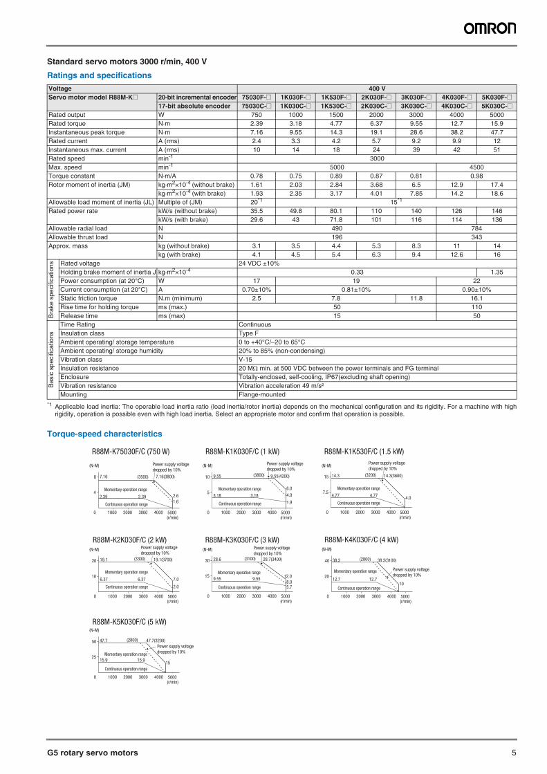
Standard servo motors 3000 r/min, 400 V
Ratings and specifications
Torque-speed characteristics
Voltage 400 VServo motor model R88M-K@ 20-bit incremental encoder 75030F-@ 1K030F-@ 1K530F-@ 2K030F-@ 3K030F-@ 4K030F-@ 5K030F-@
17-bit absolute encoder 75030C-@ 1K030C-@ 1K530C-@ 2K030C-@ 3K030C-@ 4K030C-@ 5K030C-@Rated output W 750 1000 1500 2000 3000 4000 5000Rated torque N·m 2.39 3.18 4.77 6.37 9.55 12.7 15.9Instantaneous peak torque N·m 7.16 9.55 14.3 19.1 28.6 38.2 47.7Rated current A (rms) 2.4 3.3 4.2 5.7 9.2 9.9 12Instantaneous max. current A (rms) 10 14 18 24 39 42 51Rated speed min-1 3000Max. speed min-1 5000 4500Torque constant N·m/A 0.78 0.75 0.89 0.87 0.81 0.98Rotor moment of inertia (JM) kg·m2×10-4 (without brake) 1.61 2.03 2.84 3.68 6.5 12.9 17.4
kg·m2×10-4 (with brake) 1.93 2.35 3.17 4.01 7.85 14.2 18.6Allowable load moment of inertia (JL) Multiple of (JM) 20*1
*1 Applicable load inertia: The operable load inertia ratio (load inertia/rotor inertia) depends on the mechanical configuration and its rigidity. For a machine with highrigidity, operation is possible even with high load inertia. Select an appropriate motor and confirm that operation is possible.
15*1
Rated power rate kW/s (without brake) 35.5 49.8 80.1 110 140 126 146kW/s (with brake) 29.6 43 71.8 101 116 114 136
Allowable radial load N 490 784Allowable thrust load N 196 343Approx. mass kg (without brake) 3.1 3.5 4.4 5.3 8.3 11 14
kg (with brake) 4.1 4.5 5.4 6.3 9.4 12.6 16
Bra
ke s
peci
ficat
ions Rated voltage 24 VDC ±10%
Holding brake moment of inertia J kg·m2×10-4 0.33 1.35Power consumption (at 20°C) W 17 19 22Current consumption (at 20°C) A 0.70±10% 0.81±10% 0.90±10%Static friction torque N.m (minimum) 2.5 7.8 11.8 16.1Rise time for holding torque ms (max.) 50 110Release time ms (max) 15 50
Bas
ic s
peci
ficat
ions
Time Rating ContinuousInsulation class Type FAmbient operating/ storage temperature 0 to +40°C/–20 to 65°CAmbient operating/ storage humidity 20% to 85% (non-condensing)Vibration class V-15Insulation resistance 20 M min. at 500 VDC between the power terminals and FG terminalEnclosure Totally-enclosed, self-cooling, IP67(excluding shaft opening)Vibration resistance Vibration acceleration 49 m/s²Mounting Flange-mounted
R88M-K75030F/C (750 W) R88M-K1K030F/C (1 kW) R88M-K1K530F/C (1.5 kW)
R88M-K2K030F/C (2 kW) R88M-K3K030F/C (3 kW) R88M-K4K030F/C (4 kW)
R88M-K5K030F/C (5 kW)
25
0 1000 2000 3000 4000 5000 (r/min)
50 47.7 47.7(3200)
15.9 15.915
(2800)
Momentary operation range
Continuous operation range
Power supply voltage dropped by 10%
20
0 1000 2000 3000 4000 5000 (r/min)
40 38.2
12.7 12.7
38.2(3100)
10
(2800)
Momentary operation range
Continuous operation range
Power supply voltage dropped by 10%15
0 1000 2000 3000 4000 5000 (r/min)
30 28.6 28.7(3400)
9.55 9.55
5.7
12.0
8.0
(3100)
Momentary operation range
Continuous operation range
Power supply voltage dropped by 10%
10
0 1000 2000 3000 4000 5000 (r/min)
20 19.1
6.37 6.37
19.1(3700)
7.0
2.0
(3300)
Momentary operation range
Continuous operation range
Power supply voltage dropped by 10%
7.5
0 1000 2000 3000 4000 5000 (r/min)
15 14.3 14.3(3600)
4.77 4.774.0
(3200)
Momentary operation range
Continuous operation range
Power supply voltage dropped by 10%
5
0 1000 2000 3000 4000 5000 (r/min)
10 9.55 9.55(4200)
3.18 3.18
1.9
6.0
4.0
(3800)
Momentary operation range
Continuous operation range
Power supply voltage dropped by 10%
4
0 1000 2000 3000 4000 5000 (r/min)
8 7.16 7.16(3800)
2.39 2.39 2.6
1.6
(3500)
Momentary operation range
Continuous operation range
Power supply voltage dropped by 10%
(N-M) (N-M) (N-M)
(N-M)
(N-M)
(N-M) (N-M)
6 AC servo systems
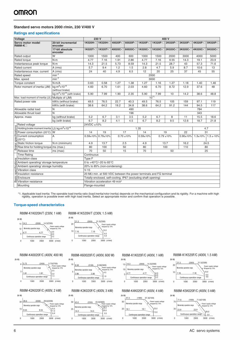
Standard servo motors 2000 r/min, 230 V/400 V
Ratings and specifications
*1. Applicable load inertia: The operable load inertia ratio (load inertia/rotor inertia) depends on the mechanical configuration and its rigidity. For a machine with high rigidity, operation is possible even with high load inertia. Select an appropriate motor and confirm that operation is possible.
Torque-speed characteristics
Voltage 230 V 400 VServo motor model R88M-K@
20-bit incremental encoder
1K020H-@ 1K520H-@ 40020F-@ 60020F-@ 1K020F-@ 1K520F-@ 2K020F-@ 3K020F-@ 4K020F-@ 5K020F-@
17-bit absoluteencoder
1K020T-@ 1K520T-@ 40020C-@ 60020C-@ 1K020C-@ 1K520C-@ 2K020C-@ 3K020C-@ 4K020C-@ 5K020C-@
Rated output W 1000 1500 400 600 1000 1500 2000 3000 4000 5000Rated torque N·m 4.77 7.16 1.91 2.86 4.77 7.16 9.55 14.3 19.1 23.9Instantaneous peak torque N·m 14.3 21.5 5.73 8.59 14.3 21.5 28.7 43 57.3 71.6Rated current A (rms) 5.7 9.4 1.2 1.5 2.8 4.7 5.9 8.7 10.6 13Instantaneous max. current A (rms) 24 40 4.9 6.5 12 20 25 37 45 55Rated speed min-1 2000Max. speed min-1 3000Torque constant N·m/A 0.63 0.58 1.27 1.38 1.27 1.16 1.27 1.18 1.40 1.46Rotor moment of inertia (JM) kg·m2×10-4
(without brake)4.60 6.70 1.61 2.03 4.60 6.70 8.72 12.9 37.6 48
kg·m2×10-4 (with brake) 5.90 7.99 1.90 2.35 5.90 7.99 10 14.2 38.6 48.8Max. load moment of inertia (JL) Multiple of (JM) 10*1
Rated power rate kW/s (without brake) 49.5 76.5 22.7 40.3 49.5 76.5 105 159 97.1 119kW/s (with brake) 38.6 64.2 19.2 34.8 38.6 64.2 91.2 144 94.5 117
Allowable radial load N 490 784Allowable thrust load N 196 343Approx. mass kg (without brake) 5.2 6.7 3.1 3.5 5.2 6.7 8 11 15.5 18.6
kg (with brake) 6.7 8.2 4.1 4.5 6.7 8.2 9.5 12.6 18.7 21.8
Bra
ke s
peci
ficat
ions
Rated voltage 24VDC ±10%Holding brake moment inertia (J) kg·m2×10-4 1.35 4.7Power consumption (20°C) W 14 19 17 14 19 22 31Current consumption (20°C)
A 0.59±10% 0.79±10% 0.70 ±10% 0.59±10% 0.79 ±10% 0.90±10% 1.3±10% 1.3 ±-10%
Static friction torque N.m (minimum) 4.9 13.7 2.5 4.9 13.7 16.2 24.5Rise time for holding torque ms (max.) 80 100 50 80 100 110 80Release time ms (max) 70 50 15 70 50 25
Bas
ic s
peci
ficat
ions
Time Rating ContinuousInsulation class Type FAmbient operating/ storage temperature 0 to +40°C/–20 to 65°CAmbient operating/ storage humidity 20% to 85% (non-condensing)Vibration class V-15Insulation resistance 20 M min. at 500 VDC between the power terminals and FG terminalEnclosure Totally-enclosed, self-cooling, IP67 (excluding shaft opening)Vibration resistance Vibration acceleration 49 m/s²Mounting Flange-mounted
R88M-K1K020H/T (230V, 1 kW) R88M-K1K520H/T (230V, 1.5 kW)
R88M-K40020F/C (400V, 400 W) R88M-K60020F/C (400V, 600 W) R88M-K1K020F/C (400V, 1 kW) R88M-K1K520F/C (400V, 1.5 kW)
R88M-K2K020F/C (400V, 2 kW) R88M-K3K020F/C (400V, 3 kW) R88M-K4K020F/C (400V, 4 kW) R88M-K5K020F/C (400V, 5 kW)
0 1000 2000
5
10
15 14.3
4.77 4.77
14.3(2200)
3000 (r/min)
6.04.0
(2000)
3.2
Momentary operation range
Continuous operation range
Power supply voltage dropped by 10%
10
0
2021.5
7.16 7.16
21.5(2300)
1000 2000 3000 (r/min)
10.0
6.0
(2000)
4.8
Momentary operation range
Continuous operation range
Power supply voltage dropped by 10%
0 1000 2000
3
6 5.73
1.91 1.91
5.73(2700)
3000 (r/min)
3.5
(2400)
2.01.3
Momentary operation range
Continuous operation range
Power supply voltage dropped by 10%
0 1000 2000
5
10 8.59
2.86 2.86
8.59(2400)
3000 (r/min)
4.5
(2100)
1.9
Momentary operation range
Continuous operation range
Power supply voltage dropped by 10%
0 1000 2000
5
10
15 14.3
4.77 4.77
14.3(2200)
3000 (r/min)
6.04.03.2
(2000)
Momentary operation range
Continuous operation range
Power supply voltage dropped by 10%
10
0
2021.5
7.16 7.16
21.5(2300)
1000 2000 3000 (r/min)
10.0
6.04.8
(2000)
Momentary operation range
Continuous operation range
Power supply voltage dropped by 10%
15
0
30 28.6
9.55 9.55
28.6(2200)
1000 2000 3000 (r/min)
15.011.06.4
(2000)
Momentary operation range
Continuous operation range
Power supply voltage dropped by 10%
25
0
50 43.0
14.3 14.3
43.0(2400)
1000 2000 3000 (r/min)
28.0
20.0
9.5
(2200)
Momentary operation range
Continuous operation range
Power supply voltage dropped by 10%
25
0
50
57.3
19.1 19.1
57.3(2100)
1000 2000 3000 (r/min)
25.0
13.0
(1900)
Momentary operation range
Continuous operation range
Power supply voltage dropped by 10%
35
0
7071.6
23.9 23.9
71.6(2100)
1000 2000 3000 (r/min)
20.0
3.0
(1900)
Momentary operation range
Continuous operation range
Power supply voltage dropped by 10%
(N-M)(N-M)
(N-M) (N-M) (N-M) (N-M)
(N-M) (N-M) (N-M) (N-M)
G5 rotary servo motors 7
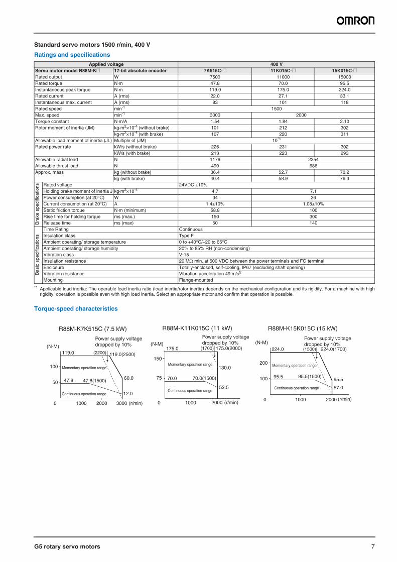
Standard servo motors 1500 r/min, 400 V
Ratings and specifications
Torque-speed characteristics
Applied voltage 400 VServo motor model R88M-K@ 17-bit absolute encoder 7K515C-@ 11K015C-@ 15K015C-@Rated output W 7500 11000 15000Rated torque N·m 47.8 70.0 95.5Instantaneous peak torque N·m 119.0 175.0 224.0Rated current A (rms) 22.0 27.1 33.1Instantaneous max. current A (rms) 83 101 118Rated speed min-1 1500Max. speed min-1 3000 2000Torque constant N·m/A 1.54 1.84 2.10Rotor moment of inertia (JM) kg·m2×10-4 (without brake) 101 212 302
kg·m2×10-4 (with brake) 107 220 311Allowable load moment of inertia (JL) Multiple of (JM) 10*1
*1 Applicable load inertia: The operable load inertia ratio (load inertia/rotor inertia) depends on the mechanical configuration and its rigidity. For a machine with highrigidity, operation is possible even with high load inertia. Select an appropriate motor and confirm that operation is possible.
Rated power rate kW/s (without brake) 226 231 302kW/s (with brake) 213 223 293
Allowable radial load N 1176 2254Allowable thrust load N 490 686Approx. mass kg (without brake) 36.4 52.7 70.2
kg (with brake) 40.4 58.9 76.3
Bra
ke s
peci
ficat
ions Rated voltage 24VDC ±10%
Holding brake moment of inertia J kg·m2×10-4 4.7 7.1Power consumption (at 20°C) W 34 26Current consumption (at 20°C) A 1.4±10% 1.08±10%Static friction torque N·m (minimum) 58.8 100Rise time for holding torque ms (max.) 150 300Release time ms (max) 50 140
Bas
ic s
peci
ficat
ions
Time Rating ContinuousInsulation class Type FAmbient operating/ storage temperature 0 to +40°C/–20 to 65°CAmbient operating/ storage humidity 20% to 85% RH (non-condensing)Vibration class V-15Insulation resistance 20 M min. at 500 VDC between the power terminals and FG terminalEnclosure Totally-enclosed, self-cooling, IP67 (excluding shaft opening)Vibration resistance Vibration acceleration 49 m/s2
Mounting Flange-mounted
75
0
150
175.0
70.0 70.0(1500)
175.0(2000)
1000 2000 (r/min)
130.0
52.5
(1700)
Momentary operation range
(N-M)
Continuous operation range
100
0
200
224.0
95.5 95.5(1500)
224.0(1700)
1000 2000 (r/min)
95.5
57.0
(1500)
Momentary operation range
(N-M)
Continuous operation range
R88M-K11K015C (11 kW) R88M-K15K015C (15 kW) R88M-K7K515C (7.5 kW)Power supply voltagedropped by 10%
Power supply voltagedropped by 10%
50
0
100
119.0
47.8 47.8(1500)
119.0(2500)
1000 2000 3000 (r/min)
60.0
12.0
(2200)(N-M)
Power supply voltagedropped by 10%
Momentary operation range
Continuous operation range
8 AC servo systems
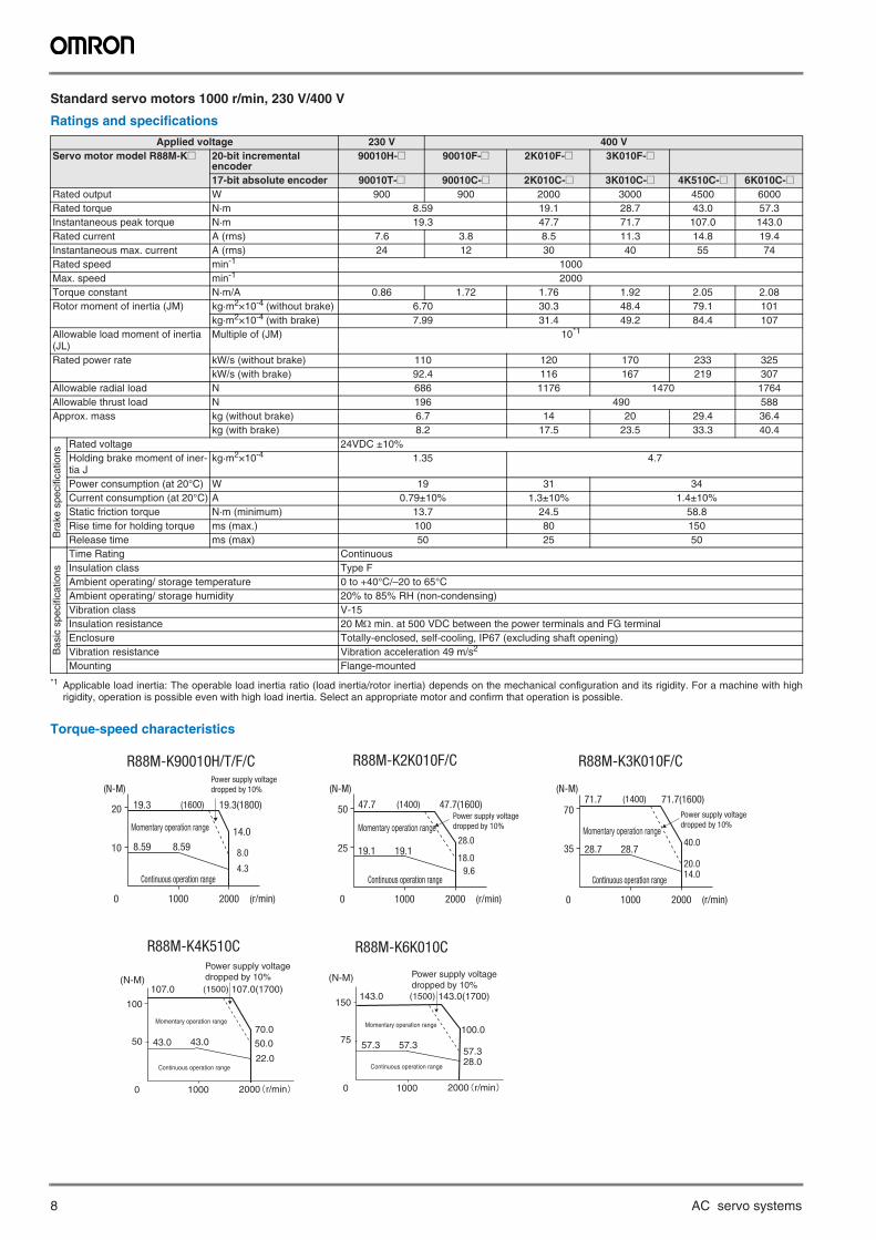
Standard servo motors 1000 r/min, 230 V/400 V
Ratings and specifications
Torque-speed characteristics
Applied voltage 230 V 400 VServo motor model R88M-K@ 20-bit incremental
encoder90010H-@ 90010F-@ 2K010F-@ 3K010F-@
17-bit absolute encoder 90010T-@ 90010C-@ 2K010C-@ 3K010C-@ 4K510C-@ 6K010C-@Rated output W 900 900 2000 3000 4500 6000Rated torque N·m 8.59 19.1 28.7 43.0 57.3Instantaneous peak torque N·m 19.3 47.7 71.7 107.0 143.0Rated current A (rms) 7.6 3.8 8.5 11.3 14.8 19.4Instantaneous max. current A (rms) 24 12 30 40 55 74Rated speed min-1 1000Max. speed min-1 2000Torque constant N·m/A 0.86 1.72 1.76 1.92 2.05 2.08Rotor moment of inertia (JM) kg·m2×10-4 (without brake) 6.70 30.3 48.4 79.1 101
kg·m2×10-4 (with brake) 7.99 31.4 49.2 84.4 107Allowable load moment of inertia (JL)
Multiple of (JM) 10*1
*1 Applicable load inertia: The operable load inertia ratio (load inertia/rotor inertia) depends on the mechanical configuration and its rigidity. For a machine with highrigidity, operation is possible even with high load inertia. Select an appropriate motor and confirm that operation is possible.
Rated power rate kW/s (without brake) 110 120 170 233 325kW/s (with brake) 92.4 116 167 219 307
Allowable radial load N 686 1176 1470 1764Allowable thrust load N 196 490 588Approx. mass kg (without brake) 6.7 14 20 29.4 36.4
kg (with brake) 8.2 17.5 23.5 33.3 40.4
Bra
ke s
peci
ficat
ions
Rated voltage 24VDC ±10%Holding brake moment of iner-tia J
kg·m2×10-4 1.35 4.7
Power consumption (at 20°C) W 19 31 34Current consumption (at 20°C) A 0.79±10% 1.3±10% 1.4±10%Static friction torque N·m (minimum) 13.7 24.5 58.8Rise time for holding torque ms (max.) 100 80 150Release time ms (max) 50 25 50
Bas
ic s
peci
ficat
ions
Time Rating ContinuousInsulation class Type FAmbient operating/ storage temperature 0 to +40°C/–20 to 65°CAmbient operating/ storage humidity 20% to 85% RH (non-condensing)Vibration class V-15Insulation resistance 20 M min. at 500 VDC between the power terminals and FG terminalEnclosure Totally-enclosed, self-cooling, IP67 (excluding shaft opening)Vibration resistance Vibration acceleration 49 m/s2
Mounting Flange-mounted
R88M-K90010H/T/F/C R88M-K2K010F/C R88M-K3K010F/C
10
0
20 19.3(1800)19.3
8.598.59
1000 2000 (r/min)
14.0
8.0
4.3
(1600)
Momentary operation range
Continuous operation range
Power supply voltage dropped by 10%
25
0
50
1000 2000 (r/min)
19.119.1
47.7(1600)47.7
28.0
18.0
9.6
(1400)
Momentary operation range
Continuous operation range
Power supply voltage dropped by 10%
35
0
70
1000 2000 (r/min)
28.728.7
71.7(1600)71.7
40.0
20.014.0
(1400)(N-M)(N-M)(N-M)
Momentary operation range
Continuous operation range
Power supply voltage dropped by 10%
50
0
100
107.0
43.0 43.0
107.0(1700)
1000 2000 r/min
50.0
70.0
(1500)
22.0
(N-M)
Momentary operation range
Continuous operation range
75
0
150143.0
57.3 57.3
143.0(1700)
1000 2000 r/min
57.3
100.0
(1500)
28.0
(N-M)
Momentary operation range
Continuous operation range
R88M-K6K010CR88M-K4K510C Power supply voltagedropped by 10% Power supply voltage
dropped by 10%
G5 rotary servo motors 9
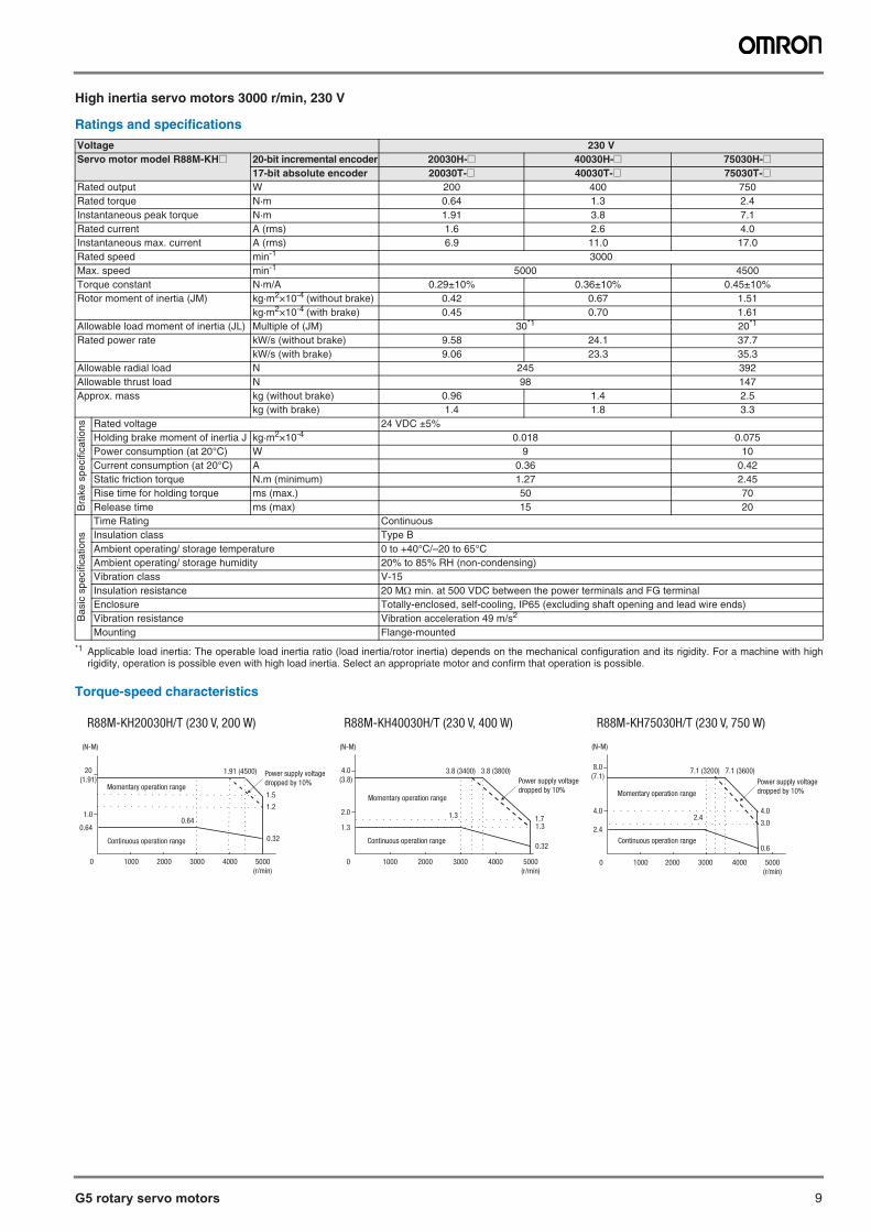
High inertia servo motors 3000 r/min, 230 V
Ratings and specifications
Voltage 230 VServo motor model R88M-KH@ 20-bit incremental encoder 20030H-@ 40030H-@ 75030H-@
17-bit absolute encoder 20030T-@ 40030T-@ 75030T-@Rated output W 200 400 750Rated torque N·m 0.64 1.3 2.4Instantaneous peak torque N·m 1.91 3.8 7.1Rated current A (rms) 1.6 2.6 4.0Instantaneous max. current A (rms) 6.9 11.0 17.0Rated speed min-1 3000Max. speed min-1 5000 4500Torque constant N·m/A 0.29±10% 0.36±10% 0.45±10%Rotor moment of inertia (JM) kg·m2×10-4 (without brake) 0.42 0.67 1.51
kg·m2×10-4 (with brake) 0.45 0.70 1.61Allowable load moment of inertia (JL) Multiple of (JM) 30*1
*1 Applicable load inertia: The operable load inertia ratio (load inertia/rotor inertia) depends on the mechanical configuration and its rigidity. For a machine with highrigidity, operation is possible even with high load inertia. Select an appropriate motor and confirm that operation is possible.
Torque-speed characteristics
20*1
Rated power rate kW/s (without brake) 9.58 24.1 37.7kW/s (with brake) 9.06 23.3 35.3
Allowable radial load N 245 392Allowable thrust load N 98 147Approx. mass kg (without brake) 0.96 1.4 2.5
kg (with brake) 1.4 1.8 3.3
Bra
ke s
peci
ficat
ions Rated voltage 24 VDC ±5%
Holding brake moment of inertia J kg·m2×10-4 0.018 0.075Power consumption (at 20°C) W 9 10Current consumption (at 20°C) A 0.36 0.42Static friction torque N.m (minimum) 1.27 2.45Rise time for holding torque ms (max.) 50 70Release time ms (max) 15 20
Bas
ic s
peci
ficat
ions
Time Rating ContinuousInsulation class Type BAmbient operating/ storage temperature 0 to +40°C/–20 to 65°CAmbient operating/ storage humidity 20% to 85% RH (non-condensing)Vibration class V-15Insulation resistance 20 M min. at 500 VDC between the power terminals and FG terminalEnclosure Totally-enclosed, self-cooling, IP65 (excluding shaft opening and lead wire ends)Vibration resistance Vibration acceleration 49 m/s2
Mounting Flange-mounted
R88M-KH20030H/T (230 V, 200 W) R88M-KH40030H/T (230 V, 400 W) R88M-KH75030H/T (230 V, 750 W)
20(1.91)
1.0
0.64
0
(N-M)
1.5
1.2
0.32
1.91 (4500)
0.64
Continuous operation range
Momentary operation range
1000 2000 3000 4000 5000(r/min)
Power supply voltagedropped by 10%
4.0(3.8)
(N-M)
2.0
1.3
0
1.3
3.8 (3400) 3.8 (3800)
Momentary operation range
Continuous operation range
Power supply voltagedropped by 10%
1.31.7
0.32
1000 2000 3000 4000 5000(r/min)
(N-M)
8.0(7.1)
4.0
2.4
0 1000 2000 3000 4000 5000(r/min)
7.1 (3200) 7.1 (3600)
4.0
3.0
0.6Continuous operation range
Momentary operation range
2.4
Power supply voltagedropped by 10%
10 AC servo systems
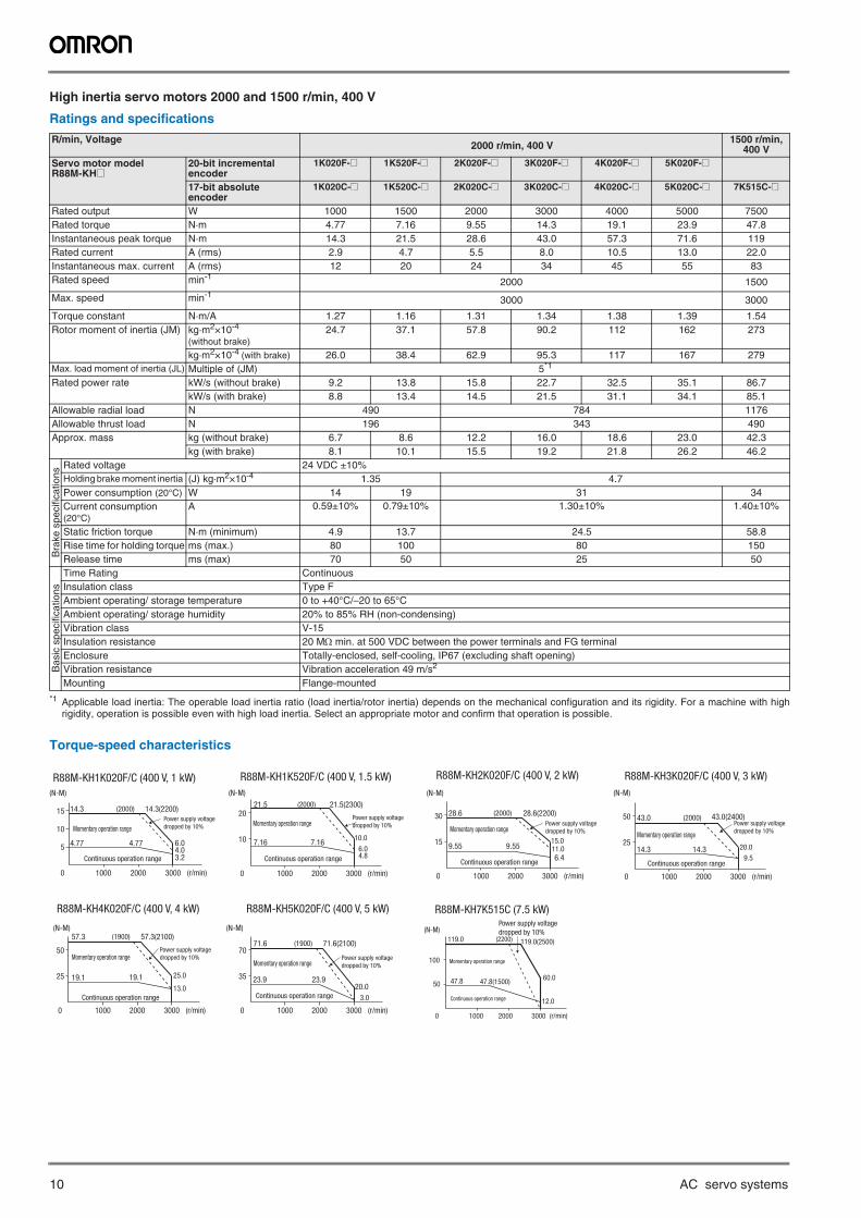
High inertia servo motors 2000 and 1500 r/min, 400 V
Ratings and specifications
Torque-speed characteristics
R/min, Voltage2000 r/min, 400 V
1500 r/min, 400 V
Servo motor model R88M-KH@
20-bit incremental encoder
1K020F-@ 1K520F-@ 2K020F-@ 3K020F-@ 4K020F-@ 5K020F-@
17-bit absoluteencoder
1K020C-@ 1K520C-@ 2K020C-@ 3K020C-@ 4K020C-@ 5K020C-@ 7K515C-@
Rated output W 1000 1500 2000 3000 4000 5000 7500Rated torque N·m 4.77 7.16 9.55 14.3 19.1 23.9 47.8Instantaneous peak torque N·m 14.3 21.5 28.6 43.0 57.3 71.6 119Rated current A (rms) 2.9 4.7 5.5 8.0 10.5 13.0 22.0Instantaneous max. current A (rms) 12 20 24 34 45 55 83Rated speed min-1
2000 1500
Max. speed min-13000 3000
Torque constant N·m/A 1.27 1.16 1.31 1.34 1.38 1.39 1.54Rotor moment of inertia (JM) kg·m2×10-4
(without brake)24.7 37.1 57.8 90.2 112 162 273
kg·m2×10-4 (with brake) 26.0 38.4 62.9 95.3 117 167 279Max. load moment of inertia (JL) Multiple of (JM) 5*1
*1 Applicable load inertia: The operable load inertia ratio (load inertia/rotor inertia) depends on the mechanical configuration and its rigidity. For a machine with highrigidity, operation is possible even with high load inertia. Select an appropriate motor and confirm that operation is possible.
Rated power rate kW/s (without brake) 9.2 13.8 15.8 22.7 32.5 35.1 86.7kW/s (with brake) 8.8 13.4 14.5 21.5 31.1 34.1 85.1
Allowable radial load N 490 784 1176Allowable thrust load N 196 343 490Approx. mass kg (without brake) 6.7 8.6 12.2 16.0 18.6 23.0 42.3
kg (with brake) 8.1 10.1 15.5 19.2 21.8 26.2 46.2
Bra
ke s
peci
ficat
ions
Rated voltage 24 VDC ±10%Holding brake moment inertia (J) kg·m2×10-4 1.35 4.7Power consumption (20°C) W 14 19 31 34Current consumption (20°C)
A 0.59±10% 0.79±10% 1.30±10% 1.40±10%
Static friction torque N·m (minimum) 4.9 13.7 24.5 58.8Rise time for holding torque ms (max.) 80 100 80 150Release time ms (max) 70 50 25 50
Bas
ic s
peci
ficat
ions
Time Rating ContinuousInsulation class Type FAmbient operating/ storage temperature 0 to +40°C/–20 to 65°CAmbient operating/ storage humidity 20% to 85% RH (non-condensing)Vibration class V-15Insulation resistance 20 M min. at 500 VDC between the power terminals and FG terminalEnclosure Totally-enclosed, self-cooling, IP67 (excluding shaft opening)Vibration resistance Vibration acceleration 49 m/s2
Mounting Flange-mounted
50
0
100
119.0
47.8 47.8(1500)
119.0(2500)
1000 2000 3000 (r/min)
60.0
12.0
(2200)
Momentary operation range
(N-M)
Continuous operation range
R88M-KH7K515C (7.5 kW)Power supply voltagedropped by 10%
R88M-KH1K020F/C (400 V, 1 kW) R88M-KH1K520F/C (400 V, 1.5 kW)
0 1000 2000
5
10
15 14.3
4.77 4.77
14.3(2200)
3000 (r/min)
6.04.03.2
(2000)
Momentary operation range
Continuous operation range
Power supply voltage dropped by 10%
10
0
2021.5
7.16 7.16
21.5(2300)
1000 2000 3000 (r/min)
10.0
6.04.8
(2000)
Momentary operation range
Continuous operation range
Power supply voltage dropped by 10%
(N-M) (N-M)
R88M-KH2K020F/C (400 V, 2 kW) R88M-KH3K020F/C (400 V, 3 kW)
15
0
30 28.6
9.55 9.55
28.6(2200)
1000 2000 3000 (r/min)
15.011.06.4
(2000)
Momentary operation range
Continuous operation range
Power supply voltage dropped by 10%
25
0
50 43.0
14.3 14.3
43.0(2400)
1000 2000 3000 (r/min)
20.09.5
(2000)
Momentary operation range
Continuous operation range
Power supply voltage dropped by 10%
(N-M) (N-M)
R88M-KH4K020F/C (400 V, 4 kW) R88M-KH5K020F/C (400 V, 5 kW)
25
0
50
57.3
19.1 19.1
57.3(2100)
1000 2000 3000 (r/min)
25.0
13.0
(1900)
Momentary operation range
Continuous operation range
Power supply voltage dropped by 10%
35
0
7071.6
23.9 23.9
71.6(2100)
1000 2000 3000 (r/min)
20.03.0
(1900)
Momentary operation range
Continuous operation range
Power supply voltage dropped by 10%
(N-M) (N-M)
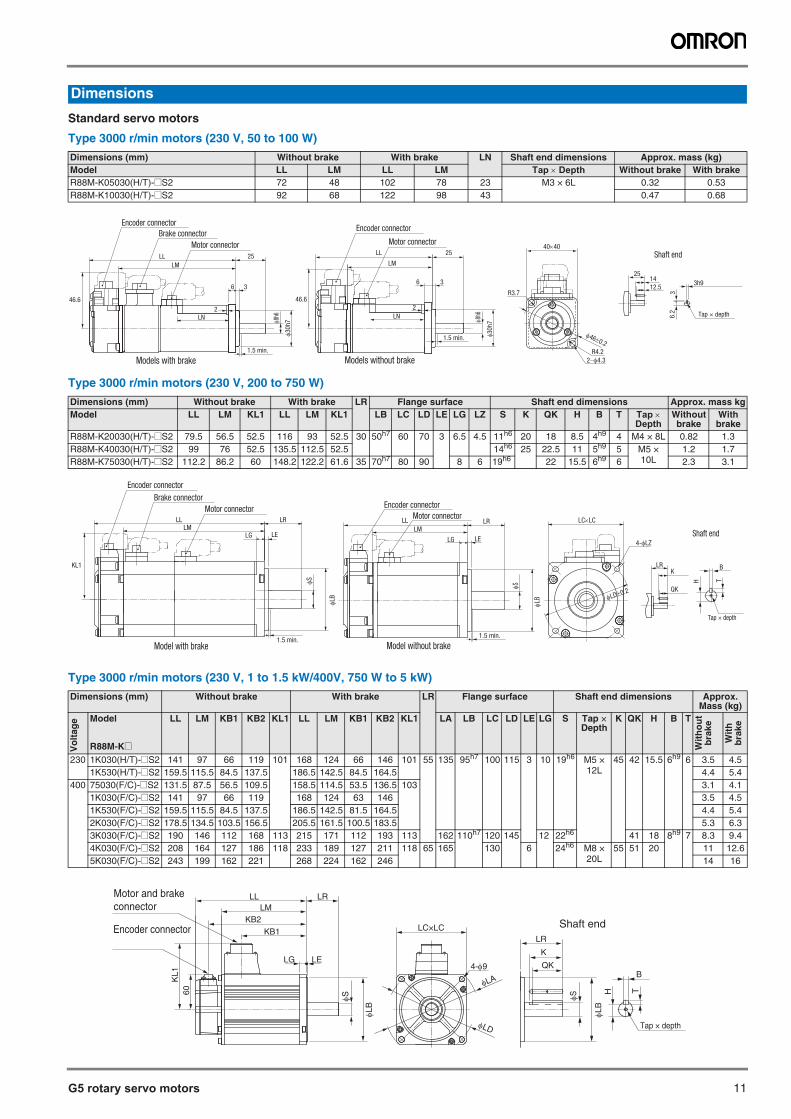
G5 rotary servo motors 11
Standard servo motors
Type 3000 r/min motors (230 V, 50 to 100 W)
Type 3000 r/min motors (230 V, 200 to 750 W)
Type 3000 r/min motors (230 V, 1 to 1.5 kW/400V, 750 W to 5 kW)
Dimensions
Dimensions (mm) Without brake With brake LN Shaft end dimensions Approx. mass (kg)Model LL LM LL LM Tap Depth Without brake With brakeR88M-K05030(H/T)-@S2 72 48 102 78 23 M3 × 6L 0.32 0.53R88M-K10030(H/T)-@S2 92 68 122 98 43 0.47 0.68
Dimensions (mm) Without brake With brake LR Flange surface Shaft end dimensions Approx. mass kgModel LL LM KL1 LL LM KL1 LB LC LD LE LG LZ S K QK H B T Tap
DepthWithout brake
With brake
R88M-K20030(H/T)-@S2 79.5 56.5 52.5 116 93 52.5 30 50h7 60 70 3 6.5 4.5 11h6 20 18 8.5 4h9
4 M4 × 8L 0.82 1.3R88M-K40030(H/T)-@S2 99 76 52.5 135.5 112.5 52.5 14h6
25 22.5 11 5h9 5 M5 ×
10L1.2 1.7
R88M-K75030(H/T)-@S2 112.2 86.2 60 148.2 122.2 61.6 35 70h7 80 90 8 6 19h6 22 15.5 6h9 6 2.3 3.1
Dimensions (mm) Without brake With brake LR Flange surface Shaft end dimensions Approx.Mass (kg)
Vol
tage
Model
R88M-K@
LL LM KB1 KB2 KL1 LL LM KB1 KB2 KL1 LA LB LC LD LE LG S Tap × Depth
K QK H B T
Wit
ho
ut
bra
ke
Wit
h
bra
ke
230 1K030(H/T)-@S2 141 97 66 119 101 168 124 66 146 101 55 135 95h7 100 115 3 10 19h6 M5 ×
12L45 42 15.5 6h9 6 3.5 4.5
1K530(H/T)-@S2 159.5 115.5 84.5 137.5 186.5 142.5 84.5 164.5 4.4 5.4400 75030(F/C)-@S2 131.5 87.5 56.5 109.5 158.5 114.5 53.5 136.5 103 3.1 4.1
1K030(F/C)-@S2 141 97 66 119 168 124 63 146 3.5 4.51K530(F/C)-@S2 159.5 115.5 84.5 137.5 186.5 142.5 81.5 164.5 4.4 5.42K030(F/C)-@S2 178.5 134.5 103.5 156.5 205.5 161.5 100.5 183.5 5.3 6.33K030(F/C)-@S2 190 146 112 168 113 215 171 112 193 113 162 110h7
120 145 12 22h6 41 18 8h9 7 8.3 9.44K030(F/C)-@S2 208 164 127 186 118 233 189 127 211 118 65 165 130 6 24h6 M8 ×
20L55 51 20 11 12.6
5K030(F/C)-@S2 243 199 162 221 268 224 162 246 14 16
Tap × depth
251412.5
3h9
36.
2
R3.7
R4.2
24.3
460.2
4040
Shaft endLL
LM
Motor connector
8h6
30h
7
25
36
2
1.5 min.
LN
Brake connectorEncoder connector
Models with brake Models without brake
46.6 46.6
8h6
30h
7
25LL
LM
6 3
1.5 min.
2
LN
Encoder connector
Motor connector
1.5 min.
LG LE
LLLM
LR
S
Model with brake
LB
S
LB
LRK
QK
LL
LMLR
LELG
LD0.2
LCLC
Shaft end
1.5 min.
4-LZ
Motor connectorEncoder connector
Model without brake
Tap × depth
B
TH
Brake connector
Encoder connector
Motor connector
KL1
Encoder connector
Motor and brakeconnector LM
KB2KB1
LRLL
KL1
60
LELG
S
LB
LC×LC
4-9
LD
LA
QK
K
LR
Tap × depth
S
LB
B
TH
Shaft end
12 AC servo systems
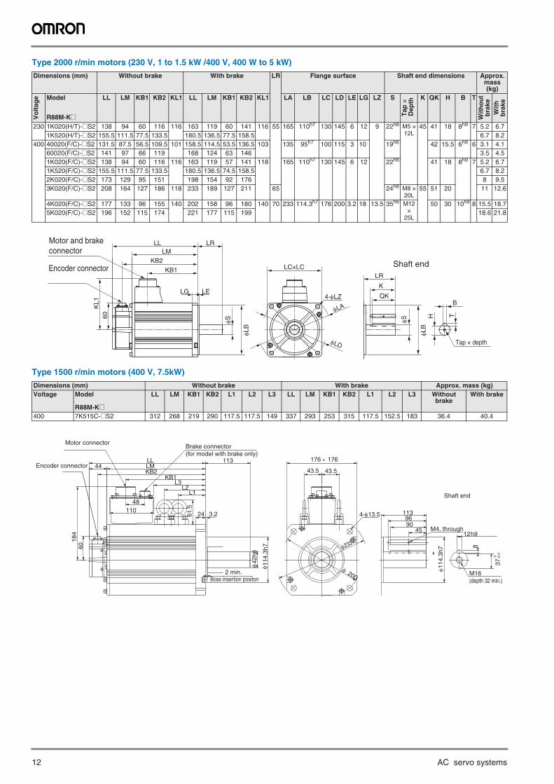
Type 2000 r/min motors (230 V, 1 to 1.5 kW /400 V, 400 W to 5 kW)
Type 1500 r/min motors (400 V, 7.5kW)
Dimensions (mm) Without brake With brake LR Flange surface Shaft end dimensions Approx.mass (kg)
Vo
ltag
e Model
R88M-K@
LL LM KB1 KB2 KL1 LL LM KB1 KB2 KL1 LA LB LC LD LE LG LZ S
Tap
× D
epth
K QK H B T
Wit
ho
ut
bra
keW
ith
b
rake
230 1K020(H/T)-@S2 138 94 60 116 116 163 119 60 141 116 55 165 110h7 130 145 6 12 9 22h6 M5 ×12L
45 41 18 8h9 7 5.2 6.71K520(H/T)-@S2 155.5 111.5 77.5 133.5 180.5 136.5 77.5 158.5 6.7 8.2
400 40020(F/C)-@S2 131.5 87.5 56.5 109.5 101 158.5 114.5 53.5 136.5 103 135 95h7 100 115 3 10 19h6 42 15.5 6h9 6 3.1 4.160020(F/C)-@S2 141 97 66 119 168 124 63 146 3.5 4.51K020(F/C)-@S2 138 94 60 116 116 163 119 57 141 118 165 110h7 130 145 6 12 22h6 41 18 8h9 7 5.2 6.71K520(F/C)-@S2 155.5 111.5 77.5 133.5 180.5 136.5 74.5 158.5 6.7 8.22K020(F/C)-@S2 173 129 95 151 198 154 92 176 8 9.53K020(F/C)-@S2 208 164 127 186 118 233 189 127 211 65 24h6 M8 ×
20L55 51 20 11 12.6
4K020(F/C)-@S2 177 133 96 155 140 202 158 96 180 140 70 233 114.3h7 176 200 3.2 18 13.5 35h6 M12 ×
25L
50 30 10h9 8 15.5 18.75K020(F/C)-@S2 196 152 115 174 221 177 115 199 18.6 21.8
Dimensions (mm) Without brake With brake Approx. mass (kg)Voltage Model
R88M-K@
LL LM KB1 KB2 L1 L2 L3 LL LM KB1 KB2 L1 L2 L3 Without brake
With brake
400 7K515C-@S2 312 268 219 290 117.5 117.5 149 337 293 253 315 117.5 152.5 183 36.4 40.4
Encoder connector
Motor and brakeconnector LM
KB2KB1
LRLL
KL1
60
LELG
φS
φLB
LC×LC
4-φLZ
φLD
φLA
QK
K
LR
Tap × depth
φS
φLB
B
TH
Shaft end
M4, through
4-φ13.5
176 × 176
43.5 43.5
φ 200
φ233
M16(depth 32 min.)
8
12h9
9045
φ114
.3h7
96113
Brake connector(for model with brake only)
3.2
φ 114
.3h7
φ42
h6
113
24
LMKB2
60
KB1
11048
L3L2
61.5
184
LL44
L1 Shaft end
2 min.Boss insertion positon
Motor connector
Encoder connector
37-0
.2 0
G5 rotary servo motors 13
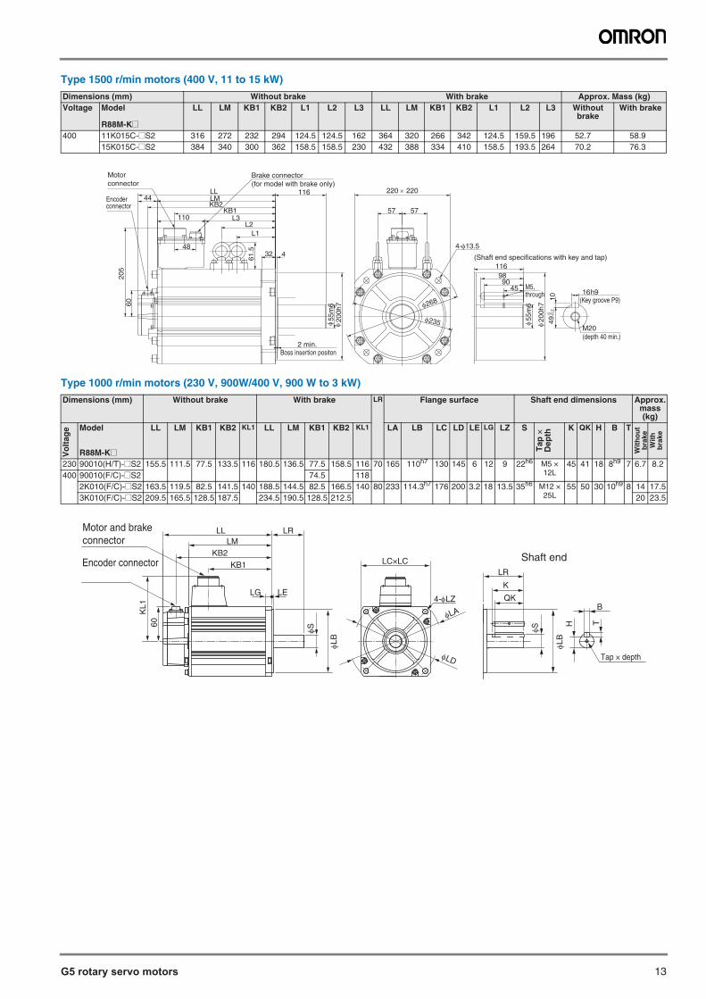
Type 1500 r/min motors (400 V, 11 to 15 kW)
Type 1000 r/min motors (230 V, 900W/400 V, 900 W to 3 kW)
Dimensions (mm) Without brake With brake Approx. Mass (kg)Voltage Model
R88M-K@
LL LM KB1 KB2 L1 L2 L3 LL LM KB1 KB2 L1 L2 L3 Without brake
With brake
400 11K015C-@S2 316 272 232 294 124.5 124.5 162 364 320 266 342 124.5 159.5 196 52.7 58.915K015C-@S2 384 340 300 362 158.5 158.5 230 432 388 334 410 158.5 193.5 264 70.2 76.3
Dimensions (mm) Without brake With brake LR Flange surface Shaft end dimensions Approx.mass (kg)
Vol
tage
Model
R88M-K@
LL LM KB1 KB2 KL1 LL LM KB1 KB2 KL1 LA LB LC LD LE LG LZ S
Tap
×D
epth
K QK H B T
Wit
ho
ut
bra
keW
ith
bra
ke
230 90010(H/T)-@S2 155.5 111.5 77.5 133.5 116 180.5 136.5 77.5 158.5 116 70 165 110h7 130 145 6 12 9 22h6 M5 × 12L
45 41 18 8h9 7 6.7 8.2400 90010(F/C)-@S2 74.5 118
2K010(F/C)-@S2 163.5 119.5 82.5 141.5 140 188.5 144.5 82.5 166.5 140 80 233 114.3h7 176 200 3.2 18 13.5 35h6 M12 ×25L
55 50 30 10h9 8 14 17.53K010(F/C)-@S2 209.5 165.5 128.5 187.5 234.5 190.5 128.5 212.5 20 23.5
(Key groove P9)
M5,through
φ20
0h7
4590
98
49 0 -0
.210
16h9
116
φ 55m
6
Brake connector(for model with brake only)
4-φ13.532
205
60
61.548
116 220 × 220
φ 55m
6
KB1KB2
L3110
φ20
0h7
LL44
L2
LM
57 57
L1
4
φ235
φ268
(Shaft end specifications with key and tap)
M20(depth 40 min.)
2 min.Boss insertion positon
Motorconnector
Encoderconnector
Encoder connector
Motor and brakeconnector LM
KB2KB1
LRLL
KL1
60
LELG
φS
φLB
LC×LC
4-φLZ
φLD
φLA
QK
K
LR
Tap × depth
φS
φLB
BTH
Shaft end
14 AC servo systems
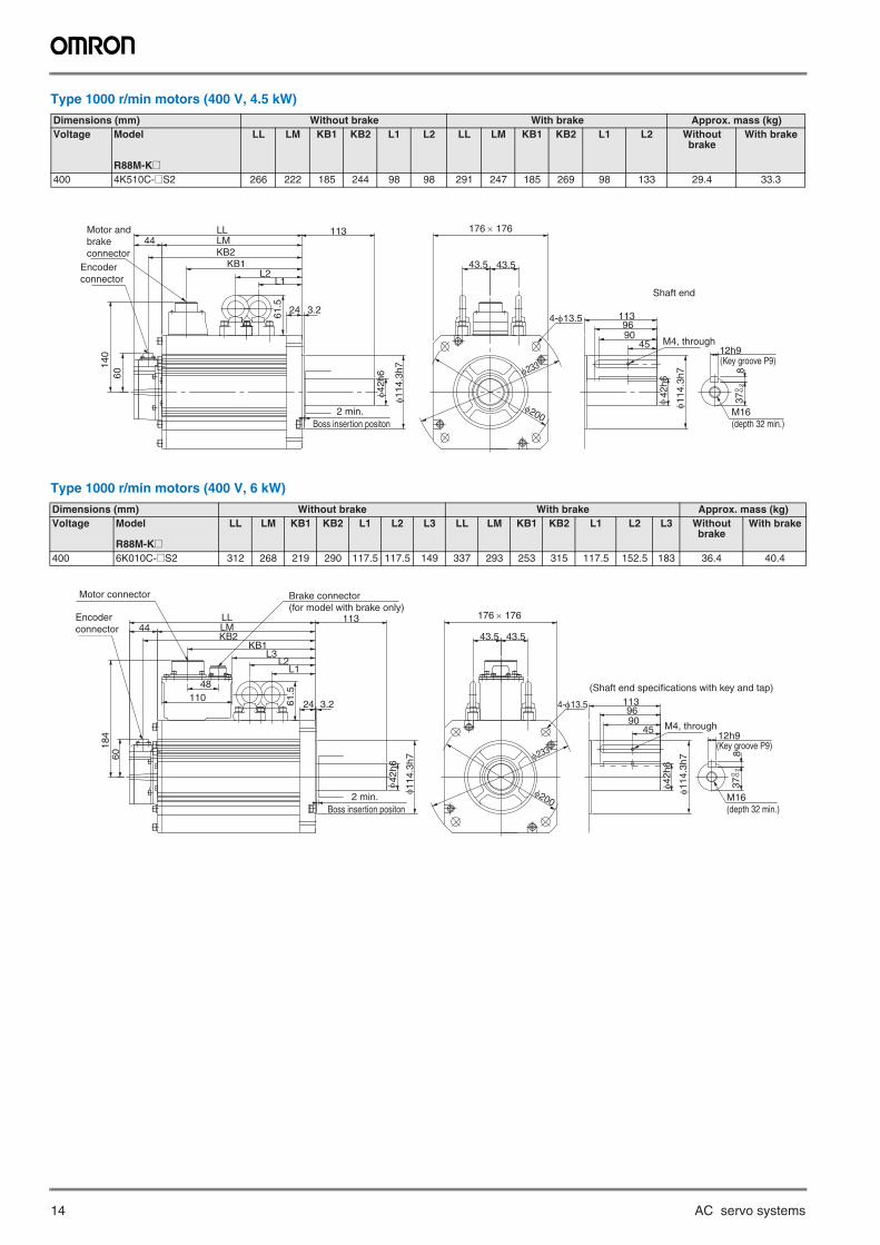
Type 1000 r/min motors (400 V, 4.5 kW)
Type 1000 r/min motors (400 V, 6 kW)
Dimensions (mm) Without brake With brake Approx. mass (kg)Voltage Model
R88M-K@
LL LM KB1 KB2 L1 L2 LL LM KB1 KB2 L1 L2 Without brake
With brake
400 4K510C-@S2 266 222 185 244 98 98 291 247 185 269 98 133 29.4 33.3
Dimensions (mm) Without brake With brake Approx. mass (kg)Voltage Model
R88M-K@
LL LM KB1 KB2 L1 L2 L3 LL LM KB1 KB2 L1 L2 L3 Without brake
With brake
400 6K010C-@S2 312 268 219 290 117.5 117.5 149 337 293 253 315 117.5 152.5 183 36.4 40.4
4-φ13.5
43.543.5
φ233
φ200
(Key groove P9)
φ 114
.3h7
φ42
h6
45
37 0 -0
.2
90
12h9
8
11396
L161
.5L2
60
KB2LM
24
113
φ 42h
6
φ 114
.3h7
3.2
KB1
140
LL44
M4, through
176 × 176
Shaft end
M16(depth 32 min.)
2 min.Boss insertion positon
Motor andbrakeconnector
Encoder connector
4-φ13.5
43.5 43.5
φ200
φ233 (Key groove P9)8
12h9
9037
0 -0.2
45
φ42h
6
φ114
.3h7
961133.2
φ 114
.3h7
φ 42h
6
113
24
LMKB2
60
KB1
11048
L3L2
61.5
184
LL44
L1
M4, through
176 × 176
(Shaft end specifications with key and tap)
Motor connector Brake connector(for model with brake only)
M16(depth 32 min.)
2 min.Boss insertion positon
Encoder connector
G5 rotary servo motors 15
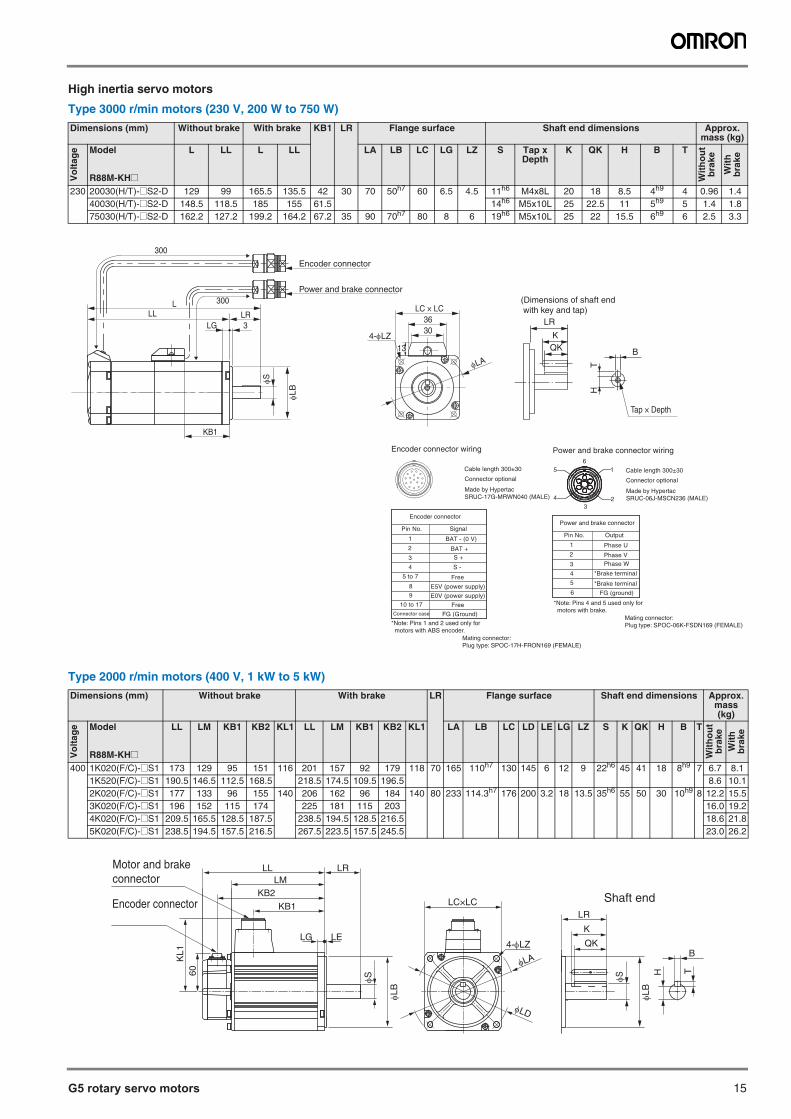
High inertia servo motors
Type 3000 r/min motors (230 V, 200 W to 750 W)
Type 2000 r/min motors (400 V, 1 kW to 5 kW)
Dimensions (mm) Without brake With brake KB1 LR Flange surface Shaft end dimensions Approx.mass (kg)
Vo
ltag
e Model
R88M-KH@
L LL L LL LA LB LC LG LZ S Tap x Depth
K QK H B T
Wit
ho
ut
bra
ke
Wit
h
bra
ke
230 20030(H/T)-@S2-D 129 99 165.5 135.5 42 30 70 50h7 60 6.5 4.5 11h6 M4x8L 20 18 8.5 4h9 4 0.96 1.440030(H/T)-@S2-D 148.5 118.5 185 155 61.5 14h6 M5x10L 25 22.5 11 5h9 5 1.4 1.875030(H/T)-@S2-D 162.2 127.2 199.2 164.2 67.2 35 90 70h7 80 8 6 19h6 M5x10L 25 22 15.5 6h9 6 2.5 3.3
Dimensions (mm) Without brake With brake LR Flange surface Shaft end dimensions Approx.mass (kg)
Vo
ltag
e Model
R88M-KH@
LL LM KB1 KB2 KL1 LL LM KB1 KB2 KL1 LA LB LC LD LE LG LZ S K QK H B T
Wit
ho
ut
bra
keW
ith
b
rake
400 1K020(F/C)-@S1 173 129 95 151 116 201 157 92 179 118 70 165 110h7 130 145 6 12 9 22h6 45 41 18 8h9 7 6.7 8.11K520(F/C)-@S1 190.5 146.5 112.5 168.5 218.5 174.5 109.5 196.5 8.6 10.12K020(F/C)-@S1 177 133 96 155 140 206 162 96 184 140 80 233 114.3h7 176 200 3.2 18 13.5 35h6 55 50 30 10h9 8 12.2 15.53K020(F/C)-@S1 196 152 115 174 225 181 115 203 16.0 19.24K020(F/C)-@S1 209.5 165.5 128.5 187.5 238.5 194.5 128.5 216.5 18.6 21.85K020(F/C)-@S1 238.5 194.5 157.5 216.5 267.5 223.5 157.5 245.5 23.0 26.2
QK
Tap × Depth
B
TH
(Dimensions of shaft end with key and tap)
Power and brake connector
Pin No. Output
Cable length 300±30
Connector optional
1
2
Phase U
Phase V
3
4
5
6 FG (ground)
Phase W
*Brake terminal
Made by HypertacSRUC-06J-MSCN236 (MALE)
Power and brake connector wiring
Mating connector:Plug type: SPOC-06K-FSDN169 (FEMALE)
16
5
4 23
*Brake terminal
*Note: Pins 4 and 5 used only formotors with brake.
Cable length 300±30
Connector optional
Made by HypertacSRUC-17G-MRWN040 (MALE)
Encoder connector wiring
Encoder connector
Pin No. Signal
1
2
BAT - (0 V)
BAT +
3
4
5 to 7
8 E5V (power supply)
S +
Free
Mating connector:Plug type: SPOC-17H-FRON169 (FEMALE)
S -
*Note: Pins 1 and 2 used only formotors with ABS encoder.
9 E0V (power supply)
10 to 17 FreeConnector case FG (Ground)
K
LR
LC × LC
3036
4-LZ
LA
13
3LGLL
LLR
S
LB
300
Encoder connector
Power and brake connector300
KB1
Encoder connector
Motor and brakeconnector LM
KB2KB1
LRLL
KL1
60
LELG
S
LB
LC×LC
4-LZ
LD
LA
QK
K
LR
S
LB
B
TH
Shaft end
16 AC servo systems
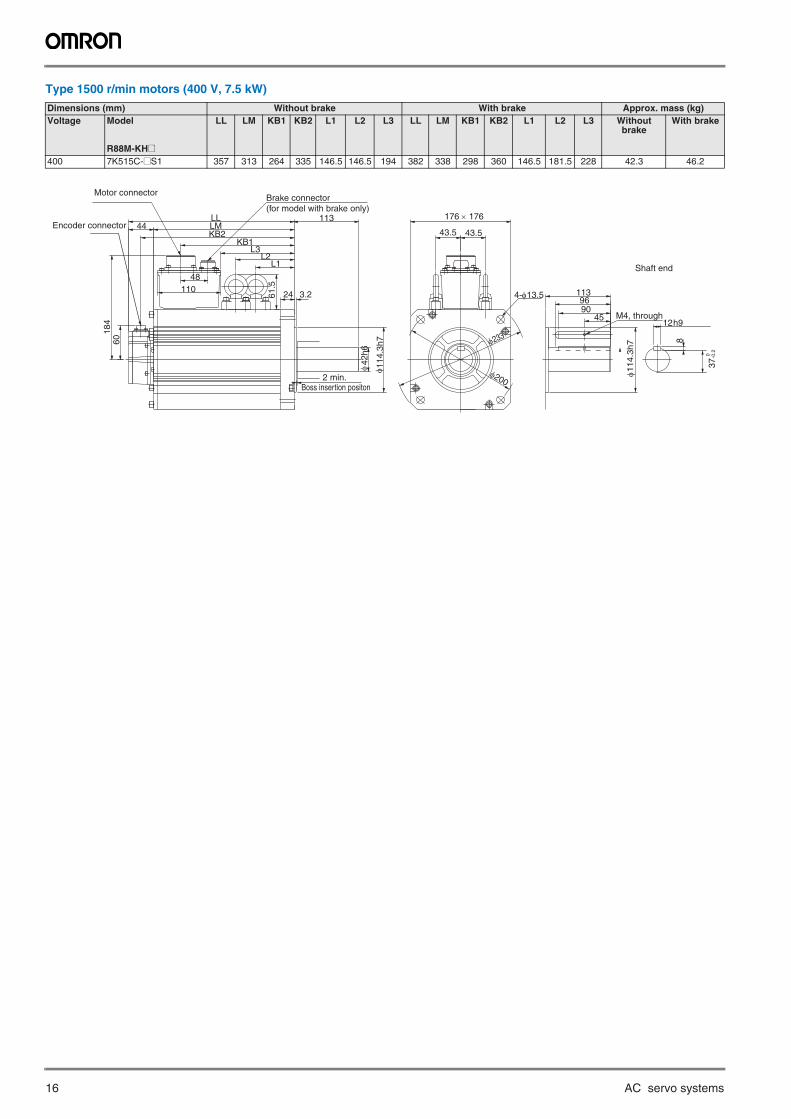
Type 1500 r/min motors (400 V, 7.5 kW)
Dimensions (mm) Without brake With brake Approx. mass (kg)Voltage Model
R88M-KH@
LL LM KB1 KB2 L1 L2 L3 LL LM KB1 KB2 L1 L2 L3 Without brake
With brake
400 7K515C-@S1 357 313 264 335 146.5 146.5 194 382 338 298 360 146.5 181.5 228 42.3 46.2
M4, through
4-φ13.5
176 × 176
43.5 43.5
φ200
φ233 8
12h9
9045
φ114
.3h7
96113
Brake connector(for model with brake only)
3.2
φ 114
.3h7
φ42
h6
113
24
LMKB2
60
KB1
11048
L3L2
61.5
184
LL44
L1 Shaft end
2 min.Boss insertion positon
Motor connector
Encoder connector
37-0
.2 0
G5 rotary servo motors 17
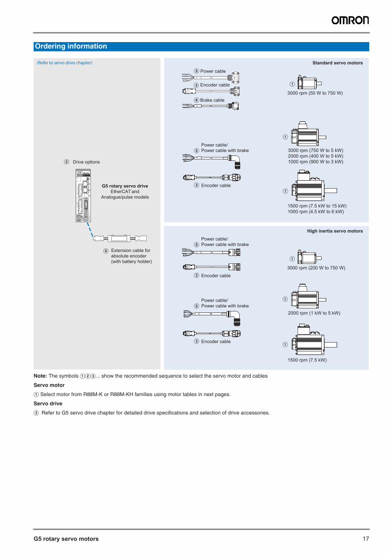
Note: The symbols ABC... show the recommended sequence to select the servo motor and cables
Servo motor
A Select motor from R88M-K or R88M-KH families using motor tables in next pages.
Servo drive
B Refer to G5 servo drive chapter for detailed drive specifications and selection of drive accessories.
Ordering information
(Refer to servo drive chapter)
3000 rpm (50 W to 750 W)
A
3000 rpm (750 W to 5 kW)2000 rpm (400 W to 5 kW)1000 rpm (900 W to 3 kW)
A
1500 rpm (7.5 kW to 15 kW)1000 rpm (4.5 kW to 6 kW)
A
2000 rpm (1 kW to 5 kW)
A
1500 rpm (7.5 kW)
A
Power cable
Encoder cable
Brake cable
C
F
E
Encoder cable
Power cable/Power cable with brake
C
E
Encoder cableC
Power cable/Power cable with brakeE
Drive options
ADR
B
D Extension cable forabsolute encoder(with battery holder)
G5 rotary servo drive EtherCAT and
Analogue/pulse models
Standard servo motors
High inertia servo motors
3000 rpm (200 W to 750 W)
A
Power cable/Power cable with brakeE
Encoder cableC
18 AC servo systems
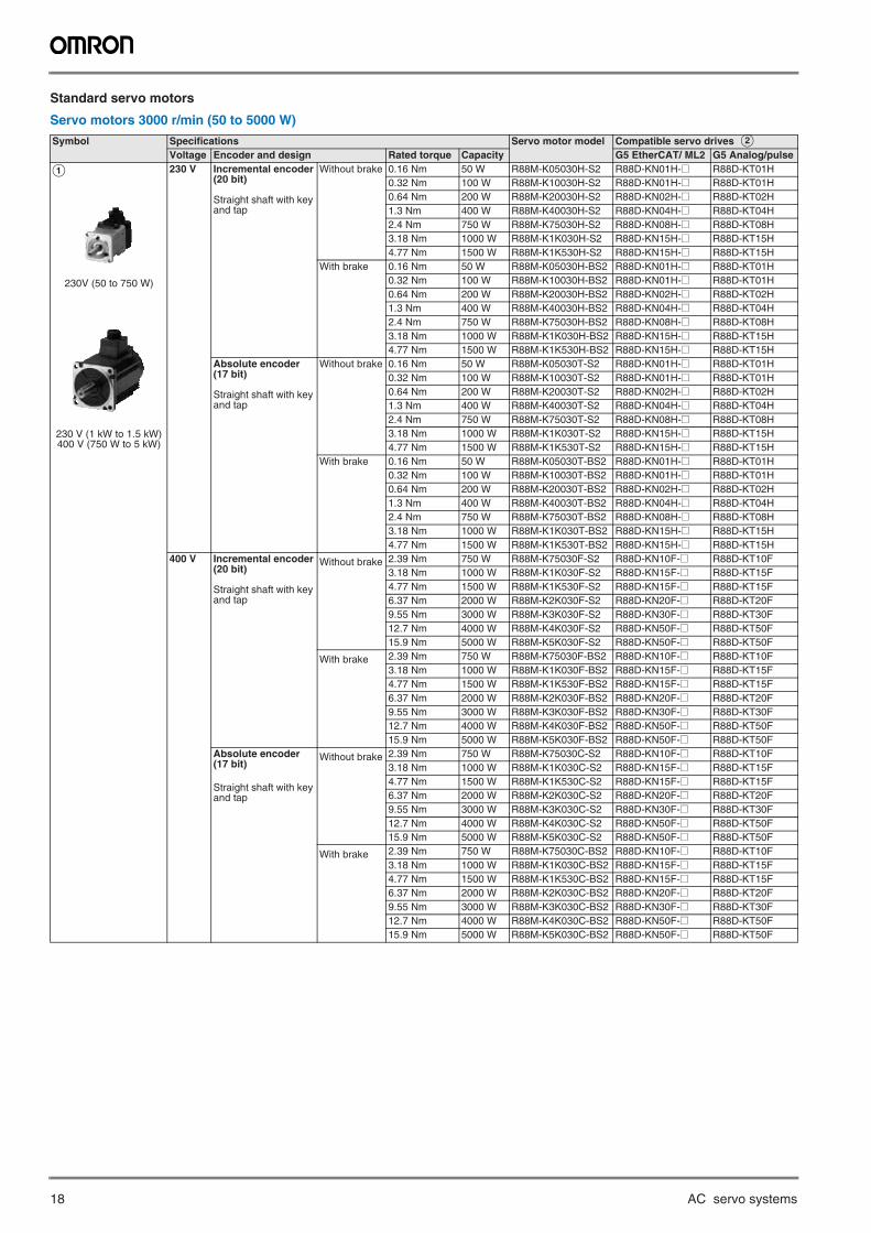
Standard servo motors
Servo motors 3000 r/min (50 to 5000 W)
Symbol Specifications Servo motor model Compatible servo drives BVoltage Encoder and design Rated torque Capacity G5 EtherCAT/ ML2 G5 Analog/pulse
A
230V (50 to 750 W)
230 V (1 kW to 1.5 kW)400 V (750 W to 5 kW)
230 V Incremental encoder(20 bit)
Straight shaft with key and tap
Without brake 0.16 Nm 50 W R88M-K05030H-S2 R88D-KN01H-@ R88D-KT01H0.32 Nm 100 W R88M-K10030H-S2 R88D-KN01H-@ R88D-KT01H0.64 Nm 200 W R88M-K20030H-S2 R88D-KN02H-@ R88D-KT02H1.3 Nm 400 W R88M-K40030H-S2 R88D-KN04H-@ R88D-KT04H2.4 Nm 750 W R88M-K75030H-S2 R88D-KN08H-@ R88D-KT08H3.18 Nm 1000 W R88M-K1K030H-S2 R88D-KN15H-@ R88D-KT15H4.77 Nm 1500 W R88M-K1K530H-S2 R88D-KN15H-@ R88D-KT15H
With brake 0.16 Nm 50 W R88M-K05030H-BS2 R88D-KN01H-@ R88D-KT01H0.32 Nm 100 W R88M-K10030H-BS2 R88D-KN01H-@ R88D-KT01H0.64 Nm 200 W R88M-K20030H-BS2 R88D-KN02H-@ R88D-KT02H1.3 Nm 400 W R88M-K40030H-BS2 R88D-KN04H-@ R88D-KT04H2.4 Nm 750 W R88M-K75030H-BS2 R88D-KN08H-@ R88D-KT08H3.18 Nm 1000 W R88M-K1K030H-BS2 R88D-KN15H-@ R88D-KT15H4.77 Nm 1500 W R88M-K1K530H-BS2 R88D-KN15H-@ R88D-KT15H
Absolute encoder(17 bit)
Straight shaft with key and tap
Without brake 0.16 Nm 50 W R88M-K05030T-S2 R88D-KN01H-@ R88D-KT01H0.32 Nm 100 W R88M-K10030T-S2 R88D-KN01H-@ R88D-KT01H0.64 Nm 200 W R88M-K20030T-S2 R88D-KN02H-@ R88D-KT02H1.3 Nm 400 W R88M-K40030T-S2 R88D-KN04H-@ R88D-KT04H2.4 Nm 750 W R88M-K75030T-S2 R88D-KN08H-@ R88D-KT08H3.18 Nm 1000 W R88M-K1K030T-S2 R88D-KN15H-@ R88D-KT15H4.77 Nm 1500 W R88M-K1K530T-S2 R88D-KN15H-@ R88D-KT15H
With brake 0.16 Nm 50 W R88M-K05030T-BS2 R88D-KN01H-@ R88D-KT01H0.32 Nm 100 W R88M-K10030T-BS2 R88D-KN01H-@ R88D-KT01H0.64 Nm 200 W R88M-K20030T-BS2 R88D-KN02H-@ R88D-KT02H1.3 Nm 400 W R88M-K40030T-BS2 R88D-KN04H-@ R88D-KT04H2.4 Nm 750 W R88M-K75030T-BS2 R88D-KN08H-@ R88D-KT08H3.18 Nm 1000 W R88M-K1K030T-BS2 R88D-KN15H-@ R88D-KT15H4.77 Nm 1500 W R88M-K1K530T-BS2 R88D-KN15H-@ R88D-KT15H
400 V Incremental encoder(20 bit)
Straight shaft with key and tap
Without brake 2.39 Nm 750 W R88M-K75030F-S2 R88D-KN10F-@ R88D-KT10F3.18 Nm 1000 W R88M-K1K030F-S2 R88D-KN15F-@ R88D-KT15F4.77 Nm 1500 W R88M-K1K530F-S2 R88D-KN15F-@ R88D-KT15F6.37 Nm 2000 W R88M-K2K030F-S2 R88D-KN20F-@ R88D-KT20F9.55 Nm 3000 W R88M-K3K030F-S2 R88D-KN30F-@ R88D-KT30F12.7 Nm 4000 W R88M-K4K030F-S2 R88D-KN50F-@ R88D-KT50F15.9 Nm 5000 W R88M-K5K030F-S2 R88D-KN50F-@ R88D-KT50F
With brake 2.39 Nm 750 W R88M-K75030F-BS2 R88D-KN10F-@ R88D-KT10F3.18 Nm 1000 W R88M-K1K030F-BS2 R88D-KN15F-@ R88D-KT15F4.77 Nm 1500 W R88M-K1K530F-BS2 R88D-KN15F-@ R88D-KT15F6.37 Nm 2000 W R88M-K2K030F-BS2 R88D-KN20F-@ R88D-KT20F9.55 Nm 3000 W R88M-K3K030F-BS2 R88D-KN30F-@ R88D-KT30F12.7 Nm 4000 W R88M-K4K030F-BS2 R88D-KN50F-@ R88D-KT50F15.9 Nm 5000 W R88M-K5K030F-BS2 R88D-KN50F-@ R88D-KT50F
Absolute encoder(17 bit)
Straight shaft with key and tap
Without brake 2.39 Nm 750 W R88M-K75030C-S2 R88D-KN10F-@ R88D-KT10F3.18 Nm 1000 W R88M-K1K030C-S2 R88D-KN15F-@ R88D-KT15F4.77 Nm 1500 W R88M-K1K530C-S2 R88D-KN15F-@ R88D-KT15F6.37 Nm 2000 W R88M-K2K030C-S2 R88D-KN20F-@ R88D-KT20F9.55 Nm 3000 W R88M-K3K030C-S2 R88D-KN30F-@ R88D-KT30F12.7 Nm 4000 W R88M-K4K030C-S2 R88D-KN50F-@ R88D-KT50F15.9 Nm 5000 W R88M-K5K030C-S2 R88D-KN50F-@ R88D-KT50F
With brake 2.39 Nm 750 W R88M-K75030C-BS2 R88D-KN10F-@ R88D-KT10F3.18 Nm 1000 W R88M-K1K030C-BS2 R88D-KN15F-@ R88D-KT15F4.77 Nm 1500 W R88M-K1K530C-BS2 R88D-KN15F-@ R88D-KT15F6.37 Nm 2000 W R88M-K2K030C-BS2 R88D-KN20F-@ R88D-KT20F9.55 Nm 3000 W R88M-K3K030C-BS2 R88D-KN30F-@ R88D-KT30F12.7 Nm 4000 W R88M-K4K030C-BS2 R88D-KN50F-@ R88D-KT50F15.9 Nm 5000 W R88M-K5K030C-BS2 R88D-KN50F-@ R88D-KT50F
G5 rotary servo motors 19
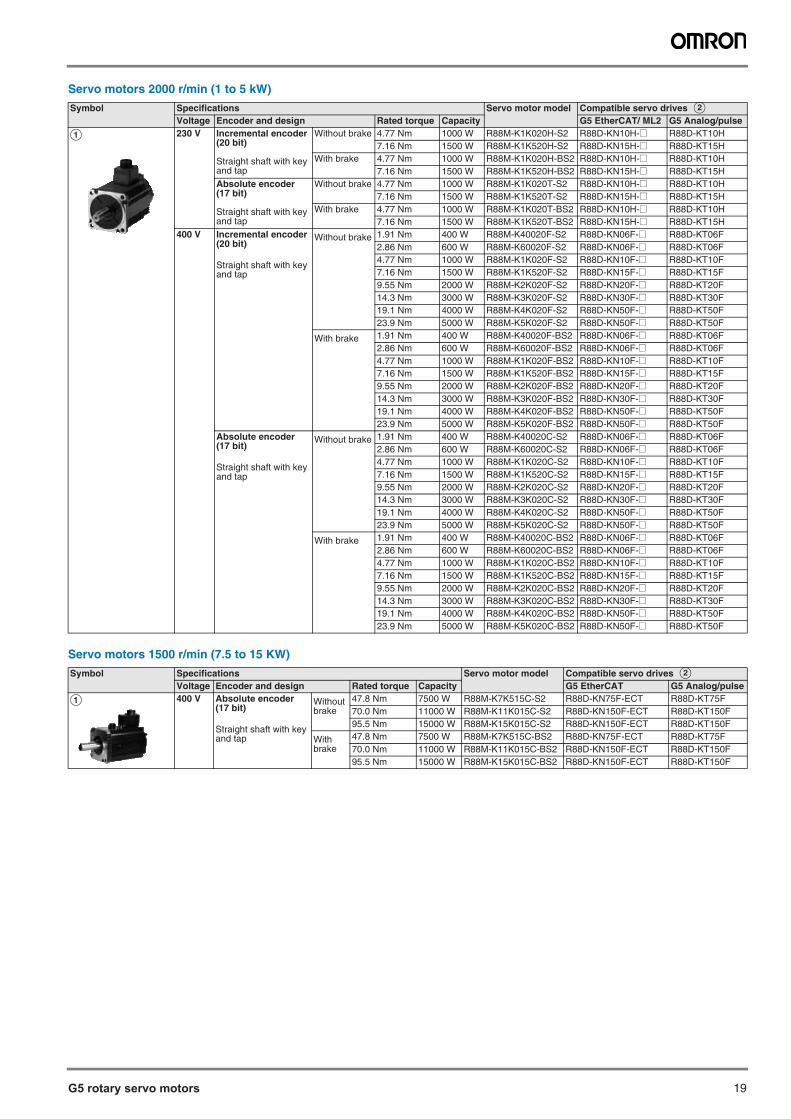
Servo motors 2000 r/min (1 to 5 kW)
Servo motors 1500 r/min (7.5 to 15 KW)
Symbol Specifications Servo motor model Compatible servo drives BVoltage Encoder and design Rated torque Capacity G5 EtherCAT/ ML2 G5 Analog/pulse
A 230 V Incremental encoder(20 bit)
Straight shaft with key and tap
Without brake 4.77 Nm 1000 W R88M-K1K020H-S2 R88D-KN10H-@ R88D-KT10H7.16 Nm 1500 W R88M-K1K520H-S2 R88D-KN15H-@ R88D-KT15H
With brake 4.77 Nm 1000 W R88M-K1K020H-BS2 R88D-KN10H-@ R88D-KT10H7.16 Nm 1500 W R88M-K1K520H-BS2 R88D-KN15H-@ R88D-KT15H
Absolute encoder(17 bit)
Straight shaft with key and tap
Without brake 4.77 Nm 1000 W R88M-K1K020T-S2 R88D-KN10H-@ R88D-KT10H7.16 Nm 1500 W R88M-K1K520T-S2 R88D-KN15H-@ R88D-KT15H
With brake 4.77 Nm 1000 W R88M-K1K020T-BS2 R88D-KN10H-@ R88D-KT10H7.16 Nm 1500 W R88M-K1K520T-BS2 R88D-KN15H-@ R88D-KT15H
400 V Incremental encoder(20 bit)
Straight shaft with key and tap
Without brake 1.91 Nm 400 W R88M-K40020F-S2 R88D-KN06F-@ R88D-KT06F2.86 Nm 600 W R88M-K60020F-S2 R88D-KN06F-@ R88D-KT06F4.77 Nm 1000 W R88M-K1K020F-S2 R88D-KN10F-@ R88D-KT10F7.16 Nm 1500 W R88M-K1K520F-S2 R88D-KN15F-@ R88D-KT15F9.55 Nm 2000 W R88M-K2K020F-S2 R88D-KN20F-@ R88D-KT20F14.3 Nm 3000 W R88M-K3K020F-S2 R88D-KN30F-@ R88D-KT30F19.1 Nm 4000 W R88M-K4K020F-S2 R88D-KN50F-@ R88D-KT50F23.9 Nm 5000 W R88M-K5K020F-S2 R88D-KN50F-@ R88D-KT50F
With brake 1.91 Nm 400 W R88M-K40020F-BS2 R88D-KN06F-@ R88D-KT06F2.86 Nm 600 W R88M-K60020F-BS2 R88D-KN06F-@ R88D-KT06F4.77 Nm 1000 W R88M-K1K020F-BS2 R88D-KN10F-@ R88D-KT10F7.16 Nm 1500 W R88M-K1K520F-BS2 R88D-KN15F-@ R88D-KT15F9.55 Nm 2000 W R88M-K2K020F-BS2 R88D-KN20F-@ R88D-KT20F14.3 Nm 3000 W R88M-K3K020F-BS2 R88D-KN30F-@ R88D-KT30F19.1 Nm 4000 W R88M-K4K020F-BS2 R88D-KN50F-@ R88D-KT50F23.9 Nm 5000 W R88M-K5K020F-BS2 R88D-KN50F-@ R88D-KT50F
Absolute encoder(17 bit)
Straight shaft with key and tap
Without brake 1.91 Nm 400 W R88M-K40020C-S2 R88D-KN06F-@ R88D-KT06F2.86 Nm 600 W R88M-K60020C-S2 R88D-KN06F-@ R88D-KT06F4.77 Nm 1000 W R88M-K1K020C-S2 R88D-KN10F-@ R88D-KT10F7.16 Nm 1500 W R88M-K1K520C-S2 R88D-KN15F-@ R88D-KT15F9.55 Nm 2000 W R88M-K2K020C-S2 R88D-KN20F-@ R88D-KT20F14.3 Nm 3000 W R88M-K3K020C-S2 R88D-KN30F-@ R88D-KT30F19.1 Nm 4000 W R88M-K4K020C-S2 R88D-KN50F-@ R88D-KT50F23.9 Nm 5000 W R88M-K5K020C-S2 R88D-KN50F-@ R88D-KT50F
With brake 1.91 Nm 400 W R88M-K40020C-BS2 R88D-KN06F-@ R88D-KT06F2.86 Nm 600 W R88M-K60020C-BS2 R88D-KN06F-@ R88D-KT06F4.77 Nm 1000 W R88M-K1K020C-BS2 R88D-KN10F-@ R88D-KT10F7.16 Nm 1500 W R88M-K1K520C-BS2 R88D-KN15F-@ R88D-KT15F9.55 Nm 2000 W R88M-K2K020C-BS2 R88D-KN20F-@ R88D-KT20F14.3 Nm 3000 W R88M-K3K020C-BS2 R88D-KN30F-@ R88D-KT30F19.1 Nm 4000 W R88M-K4K020C-BS2 R88D-KN50F-@ R88D-KT50F23.9 Nm 5000 W R88M-K5K020C-BS2 R88D-KN50F-@ R88D-KT50F
Symbol Specifications Servo motor model Compatible servo drives BVoltage Encoder and design Rated torque Capacity G5 EtherCAT G5 Analog/pulse
A 400 V Absolute encoder(17 bit)
Straight shaft with key and tap
Without brake
47.8 Nm 7500 W R88M-K7K515C-S2 R88D-KN75F-ECT R88D-KT75F70.0 Nm 11000 W R88M-K11K015C-S2 R88D-KN150F-ECT R88D-KT150F95.5 Nm 15000 W R88M-K15K015C-S2 R88D-KN150F-ECT R88D-KT150F
With brake
47.8 Nm 7500 W R88M-K7K515C-BS2 R88D-KN75F-ECT R88D-KT75F70.0 Nm 11000 W R88M-K11K015C-BS2 R88D-KN150F-ECT R88D-KT150F95.5 Nm 15000 W R88M-K15K015C-BS2 R88D-KN150F-ECT R88D-KT150F
20 AC servo systems
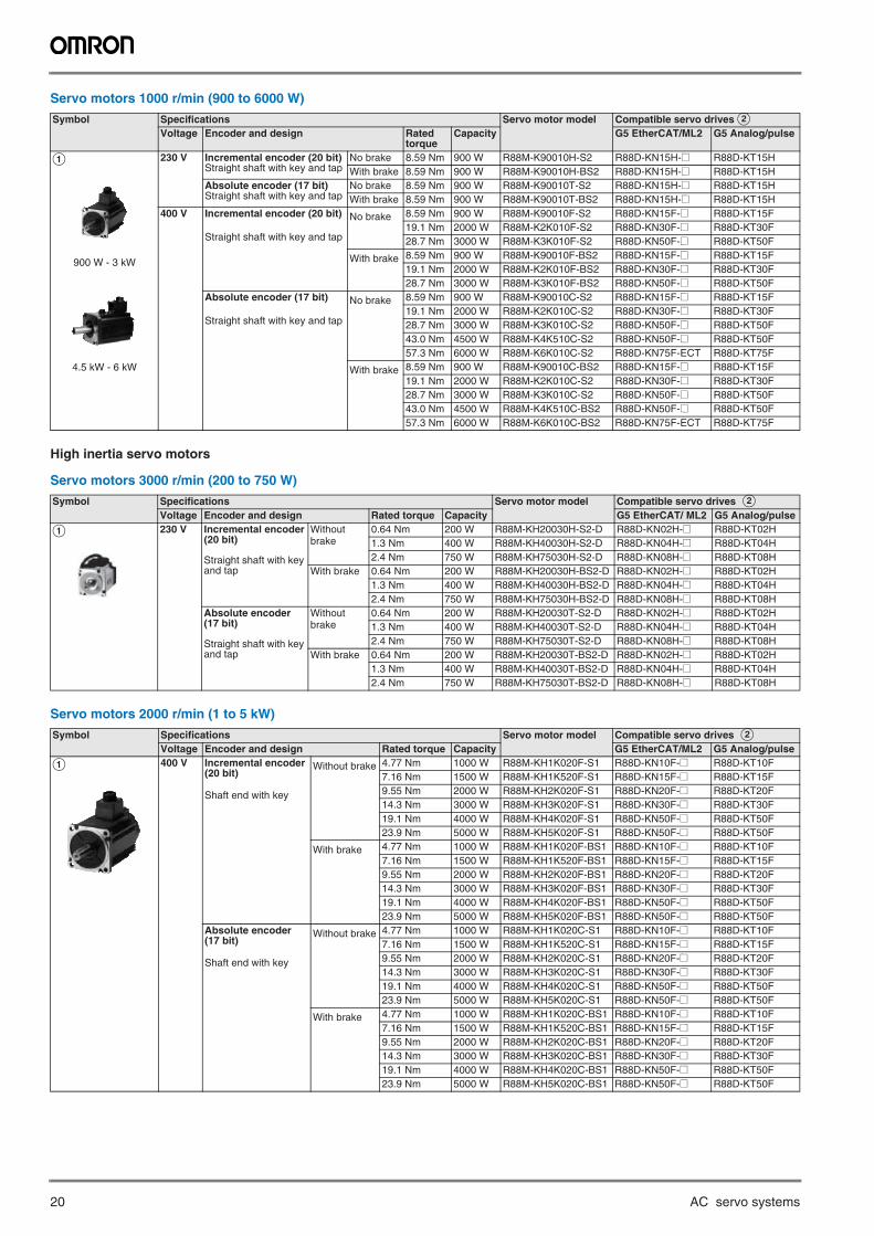
Servo motors 1000 r/min (900 to 6000 W)
High inertia servo motors
Servo motors 3000 r/min (200 to 750 W)
Servo motors 2000 r/min (1 to 5 kW)
Symbol Specifications Servo motor model Compatible servo drives BVoltage Encoder and design Rated
torqueCapacity G5 EtherCAT/ML2 G5 Analog/pulse
A
900 W - 3 kW
4.5 kW - 6 kW
230 V Incremental encoder (20 bit)Straight shaft with key and tap
No brake 8.59 Nm 900 W R88M-K90010H-S2 R88D-KN15H-@ R88D-KT15HWith brake 8.59 Nm 900 W R88M-K90010H-BS2 R88D-KN15H-@ R88D-KT15H
Absolute encoder (17 bit)Straight shaft with key and tap
No brake 8.59 Nm 900 W R88M-K90010T-S2 R88D-KN15H-@ R88D-KT15HWith brake 8.59 Nm 900 W R88M-K90010T-BS2 R88D-KN15H-@ R88D-KT15H
400 V Incremental encoder (20 bit)
Straight shaft with key and tap
No brake 8.59 Nm 900 W R88M-K90010F-S2 R88D-KN15F-@ R88D-KT15F19.1 Nm 2000 W R88M-K2K010F-S2 R88D-KN30F-@ R88D-KT30F28.7 Nm 3000 W R88M-K3K010F-S2 R88D-KN50F-@ R88D-KT50F
With brake 8.59 Nm 900 W R88M-K90010F-BS2 R88D-KN15F-@ R88D-KT15F19.1 Nm 2000 W R88M-K2K010F-BS2 R88D-KN30F-@ R88D-KT30F28.7 Nm 3000 W R88M-K3K010F-BS2 R88D-KN50F-@ R88D-KT50F
Absolute encoder (17 bit)
Straight shaft with key and tap
No brake 8.59 Nm 900 W R88M-K90010C-S2 R88D-KN15F-@ R88D-KT15F19.1 Nm 2000 W R88M-K2K010C-S2 R88D-KN30F-@ R88D-KT30F28.7 Nm 3000 W R88M-K3K010C-S2 R88D-KN50F-@ R88D-KT50F43.0 Nm 4500 W R88M-K4K510C-S2 R88D-KN50F-@ R88D-KT50F57.3 Nm 6000 W R88M-K6K010C-S2 R88D-KN75F-ECT R88D-KT75F
With brake 8.59 Nm 900 W R88M-K90010C-BS2 R88D-KN15F-@ R88D-KT15F19.1 Nm 2000 W R88M-K2K010C-S2 R88D-KN30F-@ R88D-KT30F28.7 Nm 3000 W R88M-K3K010C-S2 R88D-KN50F-@ R88D-KT50F43.0 Nm 4500 W R88M-K4K510C-BS2 R88D-KN50F-@ R88D-KT50F57.3 Nm 6000 W R88M-K6K010C-BS2 R88D-KN75F-ECT R88D-KT75F
Symbol Specifications Servo motor model Compatible servo drives BVoltage Encoder and design Rated torque Capacity G5 EtherCAT/ ML2 G5 Analog/pulse
A 230 V Incremental encoder(20 bit)
Straight shaft with key and tap
Without brake
0.64 Nm 200 W R88M-KH20030H-S2-D R88D-KN02H-@ R88D-KT02H1.3 Nm 400 W R88M-KH40030H-S2-D R88D-KN04H-@ R88D-KT04H2.4 Nm 750 W R88M-KH75030H-S2-D R88D-KN08H-@ R88D-KT08H
With brake 0.64 Nm 200 W R88M-KH20030H-BS2-D R88D-KN02H-@ R88D-KT02H1.3 Nm 400 W R88M-KH40030H-BS2-D R88D-KN04H-@ R88D-KT04H2.4 Nm 750 W R88M-KH75030H-BS2-D R88D-KN08H-@ R88D-KT08H
Absolute encoder(17 bit)
Straight shaft with key and tap
Without brake
0.64 Nm 200 W R88M-KH20030T-S2-D R88D-KN02H-@ R88D-KT02H1.3 Nm 400 W R88M-KH40030T-S2-D R88D-KN04H-@ R88D-KT04H2.4 Nm 750 W R88M-KH75030T-S2-D R88D-KN08H-@ R88D-KT08H
With brake 0.64 Nm 200 W R88M-KH20030T-BS2-D R88D-KN02H-@ R88D-KT02H1.3 Nm 400 W R88M-KH40030T-BS2-D R88D-KN04H-@ R88D-KT04H2.4 Nm 750 W R88M-KH75030T-BS2-D R88D-KN08H-@ R88D-KT08H
Symbol Specifications Servo motor model Compatible servo drives BVoltage Encoder and design Rated torque Capacity G5 EtherCAT/ML2 G5 Analog/pulse
A 400 V Incremental encoder(20 bit)
Shaft end with key
Without brake 4.77 Nm 1000 W R88M-KH1K020F-S1 R88D-KN10F-@ R88D-KT10F7.16 Nm 1500 W R88M-KH1K520F-S1 R88D-KN15F-@ R88D-KT15F9.55 Nm 2000 W R88M-KH2K020F-S1 R88D-KN20F-@ R88D-KT20F14.3 Nm 3000 W R88M-KH3K020F-S1 R88D-KN30F-@ R88D-KT30F19.1 Nm 4000 W R88M-KH4K020F-S1 R88D-KN50F-@ R88D-KT50F23.9 Nm 5000 W R88M-KH5K020F-S1 R88D-KN50F-@ R88D-KT50F
With brake 4.77 Nm 1000 W R88M-KH1K020F-BS1 R88D-KN10F-@ R88D-KT10F7.16 Nm 1500 W R88M-KH1K520F-BS1 R88D-KN15F-@ R88D-KT15F9.55 Nm 2000 W R88M-KH2K020F-BS1 R88D-KN20F-@ R88D-KT20F14.3 Nm 3000 W R88M-KH3K020F-BS1 R88D-KN30F-@ R88D-KT30F19.1 Nm 4000 W R88M-KH4K020F-BS1 R88D-KN50F-@ R88D-KT50F23.9 Nm 5000 W R88M-KH5K020F-BS1 R88D-KN50F-@ R88D-KT50F
Absolute encoder(17 bit)
Shaft end with key
Without brake 4.77 Nm 1000 W R88M-KH1K020C-S1 R88D-KN10F-@ R88D-KT10F7.16 Nm 1500 W R88M-KH1K520C-S1 R88D-KN15F-@ R88D-KT15F9.55 Nm 2000 W R88M-KH2K020C-S1 R88D-KN20F-@ R88D-KT20F14.3 Nm 3000 W R88M-KH3K020C-S1 R88D-KN30F-@ R88D-KT30F19.1 Nm 4000 W R88M-KH4K020C-S1 R88D-KN50F-@ R88D-KT50F23.9 Nm 5000 W R88M-KH5K020C-S1 R88D-KN50F-@ R88D-KT50F
With brake 4.77 Nm 1000 W R88M-KH1K020C-BS1 R88D-KN10F-@ R88D-KT10F7.16 Nm 1500 W R88M-KH1K520C-BS1 R88D-KN15F-@ R88D-KT15F9.55 Nm 2000 W R88M-KH2K020C-BS1 R88D-KN20F-@ R88D-KT20F14.3 Nm 3000 W R88M-KH3K020C-BS1 R88D-KN30F-@ R88D-KT30F19.1 Nm 4000 W R88M-KH4K020C-BS1 R88D-KN50F-@ R88D-KT50F23.9 Nm 5000 W R88M-KH5K020C-BS1 R88D-KN50F-@ R88D-KT50F
G5 rotary servo motors 21
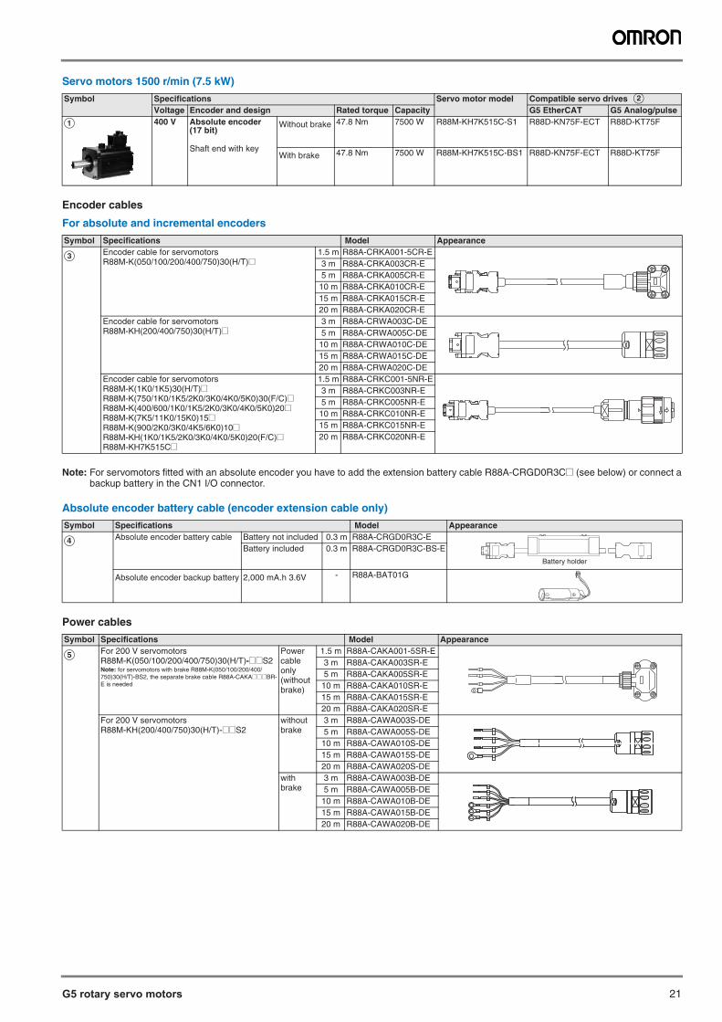
Servo motors 1500 r/min (7.5 kW)
Encoder cables
For absolute and incremental encoders
Note: For servomotors fitted with an absolute encoder you have to add the extension battery cable R88A-CRGD0R3C@ (see below) or connect abackup battery in the CN1 I/O connector.
Absolute encoder battery cable (encoder extension cable only)
Power cables
Symbol Specifications Servo motor model Compatible servo drives BVoltage Encoder and design Rated torque Capacity G5 EtherCAT G5 Analog/pulse
A 400 V Absolute encoder(17 bit)
Shaft end with key
Without brake 47.8 Nm 7500 W R88M-KH7K515C-S1 R88D-KN75F-ECT R88D-KT75F
With brake 47.8 Nm 7500 W R88M-KH7K515C-BS1 R88D-KN75F-ECT R88D-KT75F
Symbol Specifications Model Appearance
C Encoder cable for servomotorsR88M-K(050/100/200/400/750)30(H/T)@
1.5 m R88A-CRKA001-5CR-E3 m R88A-CRKA003CR-E5 m R88A-CRKA005CR-E
10 m R88A-CRKA010CR-E15 m R88A-CRKA015CR-E20 m R88A-CRKA020CR-E
Encoder cable for servomotorsR88M-KH(200/400/750)30(H/T)@
3 m R88A-CRWA003C-DE5 m R88A-CRWA005C-DE
10 m R88A-CRWA010C-DE15 m R88A-CRWA015C-DE20 m R88A-CRWA020C-DE
Encoder cable for servomotorsR88M-K(1K0/1K5)30(H/T)@R88M-K(750/1K0/1K5/2K0/3K0/4K0/5K0)30(F/C)@R88M-K(400/600/1K0/1K5/2K0/3K0/4K0/5K0)20@R88M-K(7K5/11K0/15K0)15@R88M-K(900/2K0/3K0/4K5/6K0)10@R88M-KH(1K0/1K5/2K0/3K0/4K0/5K0)20(F/C)@R88M-KH7K515C@
1.5 m R88A-CRKC001-5NR-E3 m R88A-CRKC003NR-E5 m R88A-CRKC005NR-E
10 m R88A-CRKC010NR-E15 m R88A-CRKC015NR-E20 m R88A-CRKC020NR-E
Symbol Specifications Model Appearance
D Absolute encoder battery cable Battery not included 0.3 m R88A-CRGD0R3C-EBattery included 0.3 m R88A-CRGD0R3C-BS-E
Absolute encoder backup battery 2,000 mA.h 3.6V - R88A-BAT01G
Symbol Specifications Model Appearance
E For 200 V servomotorsR88M-K(050/100/200/400/750)30(H/T)-@@S2Note: for servomotors with brake R88M-K(050/100/200/400/750)30(H/T)-BS2, the separate brake cable R88A-CAKA@@@BR-E is needed
Power cable only(without brake)
1.5 m R88A-CAKA001-5SR-E3 m R88A-CAKA003SR-E5 m R88A-CAKA005SR-E
10 m R88A-CAKA010SR-E15 m R88A-CAKA015SR-E20 m R88A-CAKA020SR-E
For 200 V servomotorsR88M-KH(200/400/750)30(H/T)-@@S2
without brake
3 m R88A-CAWA003S-DE5 m R88A-CAWA005S-DE
10 m R88A-CAWA010S-DE15 m R88A-CAWA015S-DE20 m R88A-CAWA020S-DE
with brake
3 m R88A-CAWA003B-DE5 m R88A-CAWA005B-DE
10 m R88A-CAWA010B-DE15 m R88A-CAWA015B-DE20 m R88A-CAWA020B-DE
Battery holder
22 AC servo systems
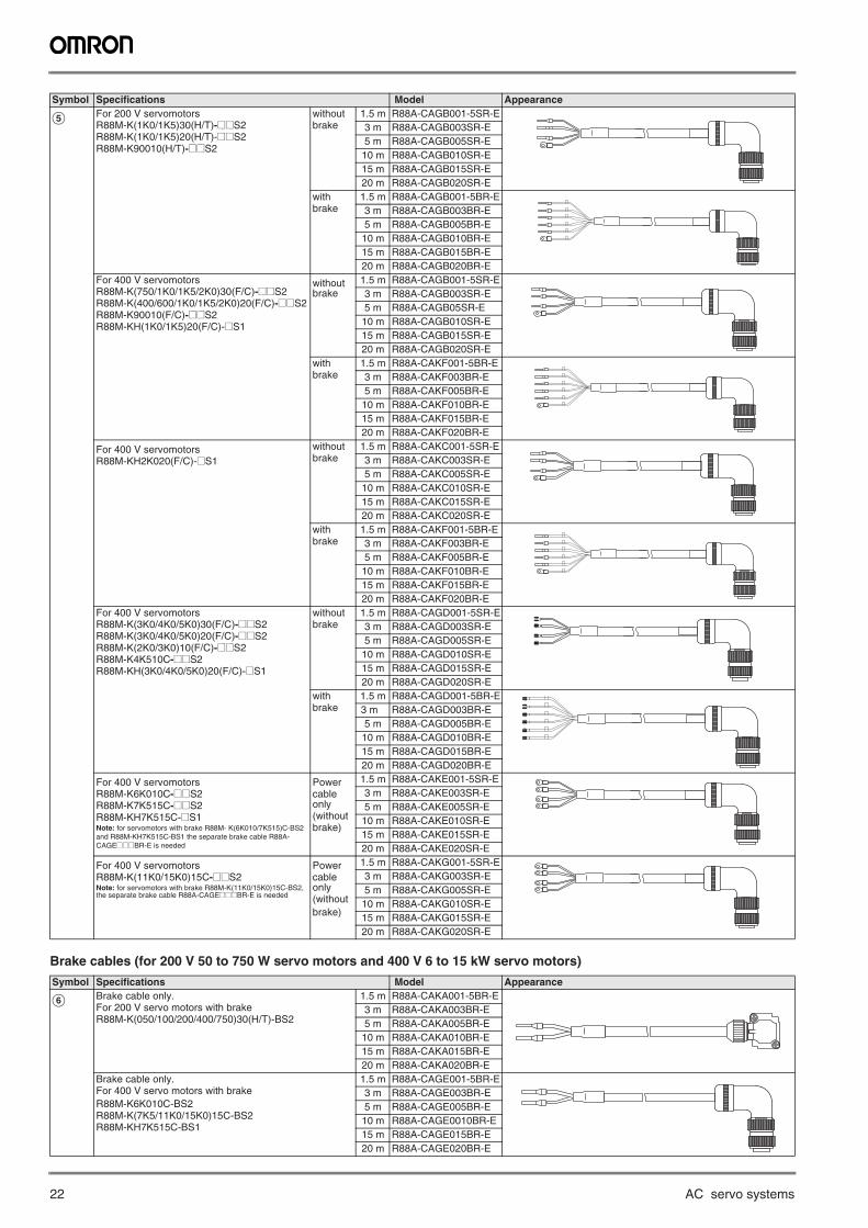
Brake cables (for 200 V 50 to 750 W servo motors and 400 V 6 to 15 kW servo motors)
E For 200 V servomotorsR88M-K(1K0/1K5)30(H/T)-@@S2R88M-K(1K0/1K5)20(H/T)-@@S2R88M-K90010(H/T)-@@S2
without brake
1.5 m R88A-CAGB001-5SR-E3 m R88A-CAGB003SR-E5 m R88A-CAGB005SR-E10 m R88A-CAGB010SR-E15 m R88A-CAGB015SR-E20 m R88A-CAGB020SR-E
with brake
1.5 m R88A-CAGB001-5BR-E3 m R88A-CAGB003BR-E5 m R88A-CAGB005BR-E10 m R88A-CAGB010BR-E15 m R88A-CAGB015BR-E20 m R88A-CAGB020BR-E
For 400 V servomotorsR88M-K(750/1K0/1K5/2K0)30(F/C)-@@S2 R88M-K(400/600/1K0/1K5/2K0)20(F/C)-@@S2 R88M-K90010(F/C)-@@S2R88M-KH(1K0/1K5)20(F/C)-@S1
without brake
1.5 m R88A-CAGB001-5SR-E3 m R88A-CAGB003SR-E5 m R88A-CAGB05SR-E10 m R88A-CAGB010SR-E15 m R88A-CAGB015SR-E20 m R88A-CAGB020SR-E
with brake
1.5 m R88A-CAKF001-5BR-E3 m R88A-CAKF003BR-E5 m R88A-CAKF005BR-E10 m R88A-CAKF010BR-E15 m R88A-CAKF015BR-E20 m R88A-CAKF020BR-E
For 400 V servomotorsR88M-KH2K020(F/C)-@S1
without brake
1.5 m R88A-CAKC001-5SR-E3 m R88A-CAKC003SR-E5 m R88A-CAKC005SR-E10 m R88A-CAKC010SR-E15 m R88A-CAKC015SR-E20 m R88A-CAKC020SR-E
with brake
1.5 m R88A-CAKF001-5BR-E3 m R88A-CAKF003BR-E5 m R88A-CAKF005BR-E10 m R88A-CAKF010BR-E15 m R88A-CAKF015BR-E20 m R88A-CAKF020BR-E
For 400 V servomotorsR88M-K(3K0/4K0/5K0)30(F/C)-@@S2R88M-K(3K0/4K0/5K0)20(F/C)-@@S2R88M-K(2K0/3K0)10(F/C)-@@S2R88M-K4K510C-@@S2R88M-KH(3K0/4K0/5K0)20(F/C)-@S1
without brake
1.5 m R88A-CAGD001-5SR-E3 m R88A-CAGD003SR-E5 m R88A-CAGD005SR-E10 m R88A-CAGD010SR-E15 m R88A-CAGD015SR-E20 m R88A-CAGD020SR-E
with brake
1.5 m R88A-CAGD001-5BR-E3 m R88A-CAGD003BR-E5 m R88A-CAGD005BR-E10 m R88A-CAGD010BR-E15 m R88A-CAGD015BR-E20 m R88A-CAGD020BR-E
For 400 V servomotorsR88M-K6K010C-@@S2R88M-K7K515C-@@S2R88M-KH7K515C-@S1Note: for servomotors with brake R88M- K(6K010/7K515)C-BS2 and R88M-KH7K515C-BS1 the separate brake cable R88A-CAGE@@@BR-E is needed
Powercable only(withoutbrake)
1.5 m R88A-CAKE001-5SR-E3 m R88A-CAKE003SR-E5 m R88A-CAKE005SR-E10 m R88A-CAKE010SR-E15 m R88A-CAKE015SR-E20 m R88A-CAKE020SR-E
For 400 V servomotorsR88M-K(11K0/15K0)15C-@@S2Note: for servomotors with brake R88M-K(11K0/15K0)15C-BS2, the separate brake cable R88A-CAGE@@@BR-E is needed
Powercable only(withoutbrake)
1.5 m R88A-CAKG001-5SR-E3 m R88A-CAKG003SR-E5 m R88A-CAKG005SR-E10 m R88A-CAKG010SR-E15 m R88A-CAKG015SR-E20 m R88A-CAKG020SR-E
Symbol Specifications Model Appearance
F Brake cable only.For 200 V servo motors with brakeR88M-K(050/100/200/400/750)30(H/T)-BS2
1.5 m R88A-CAKA001-5BR-E3 m R88A-CAKA003BR-E5 m R88A-CAKA005BR-E10 m R88A-CAKA010BR-E15 m R88A-CAKA015BR-E20 m R88A-CAKA020BR-E
Brake cable only.For 400 V servo motors with brakeR88M-K6K010C-BS2R88M-K(7K5/11K0/15K0)15C-BS2R88M-KH7K515C-BS1
1.5 m R88A-CAGE001-5BR-E3 m R88A-CAGE003BR-E5 m R88A-CAGE005BR-E10 m R88A-CAGE0010BR-E15 m R88A-CAGE015BR-E20 m R88A-CAGE020BR-E
Symbol Specifications Model Appearance
G5 rotary servo motors 23
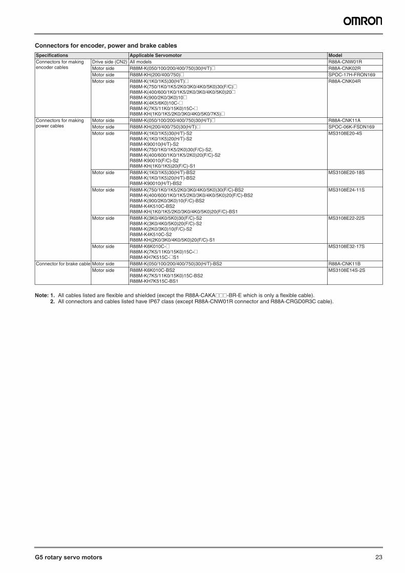
Connectors for encoder, power and brake cables
Note: 1. All cables listed are flexible and shielded (except the R88A-CAKA@@@-BR-E which is only a flexible cable).2. All connectors and cables listed have IP67 class (except R88A-CNW01R connector and R88A-CRGD0R3C cable).
Specifications Applicable Servomotor ModelConnectors for makingencoder cables
Drive side (CN2) All models R88A-CNW01RMotor side R88M-K(050/100/200/400/750)30(H/T)@ R88A-CNK02RMotor side R88M-KH(200/400/750)@ SPOC-17H-FRON169Motor side R88M-K(1K0/1K5)30(H/T)@
R88M-K(750/1K0/1K5/2K0/3K0/4K0/5K0)30(F/C)@ R88M-K(400/600/1K0/1K5/2K0/3K0/4K0/5K0)20@R88M-K(900/2K0/3K0)10@R88M-K(4K5/6K0)10C-@R88M-K(7K5/11K0/15K0)15C-@R88M-KH(1K0/1K5/2K0/3K0/4K0/5K0/7K5)@
R88A-CNK04R
Connectors for makingpower cables
Motor side R88M-K(050/100/200/400/750)30(H/T)@ R88A-CNK11AMotor side R88M-KH(200/400/750)30(H/T)@ SPOC-06K-FSDN169Motor side R88M-K(1K0/1K5)30(H/T)-S2
R88M-K(1K0/1K5)20(H/T)-S2R88M-K90010(H/T)-S2 R88M-K(750/1K0/1K5/2K0)30(F/C)-S2, R88M-K(400/600/1K0/1K5/2K0)20(F/C)-S2 R88M-K90010(F/C)-S2R88M-KH(1K0/1K5)20(F/C)-S1
MS3108E20-4S
Motor side R88M-K(1K0/1K5)30(H/T)-BS2R88M-K(1K0/1K5)20(H/T)-BS2R88M-K90010(H/T)-BS2
MS3108E20-18S
Motor side R88M-K(750/1K0/1K5/2K0/3K0/4K0/5K0)30(F/C)-BS2R88M-K(400/600/1K0/1K5/2K0/3K0/4K0/5K0)20(F/C)-BS2R88M-K(900/2K0/3K0)10(F/C)-BS2R88M-K4K510C-BS2R88M-KH(1K0/1K5/2K0/3K0/4K0/5K0)20(F/C)-BS1
MS3108E24-11S
Motor side R88M-K(3K0/4K0/5K0)30(F/C)-S2R88M-K(3K0/4K0/5K0)20(F/C)-S2R88M-K(2K0/3K0)10(F/C)-S2R88M-K4K510C-S2R88M-KH(2K0/3K0/4K0/5K0)20(F/C)-S1
MS3108E22-22S
Motor side R88M-K6K010C-@R88M-K(7K5/11K0/15K0)15C-@R88M-KH7K515C-@S1
MS3108E32-17S
Connector for brake cable Motor side R88M-K(050/100/200/400/750)30(H/T)-BS2 R88A-CNK11BMotor side R88M-K6K010C-BS2
R88M-K(7K5/11K0/15K0)15C-BS2R88M-KH7K515C-BS1
MS3108E14S-2S
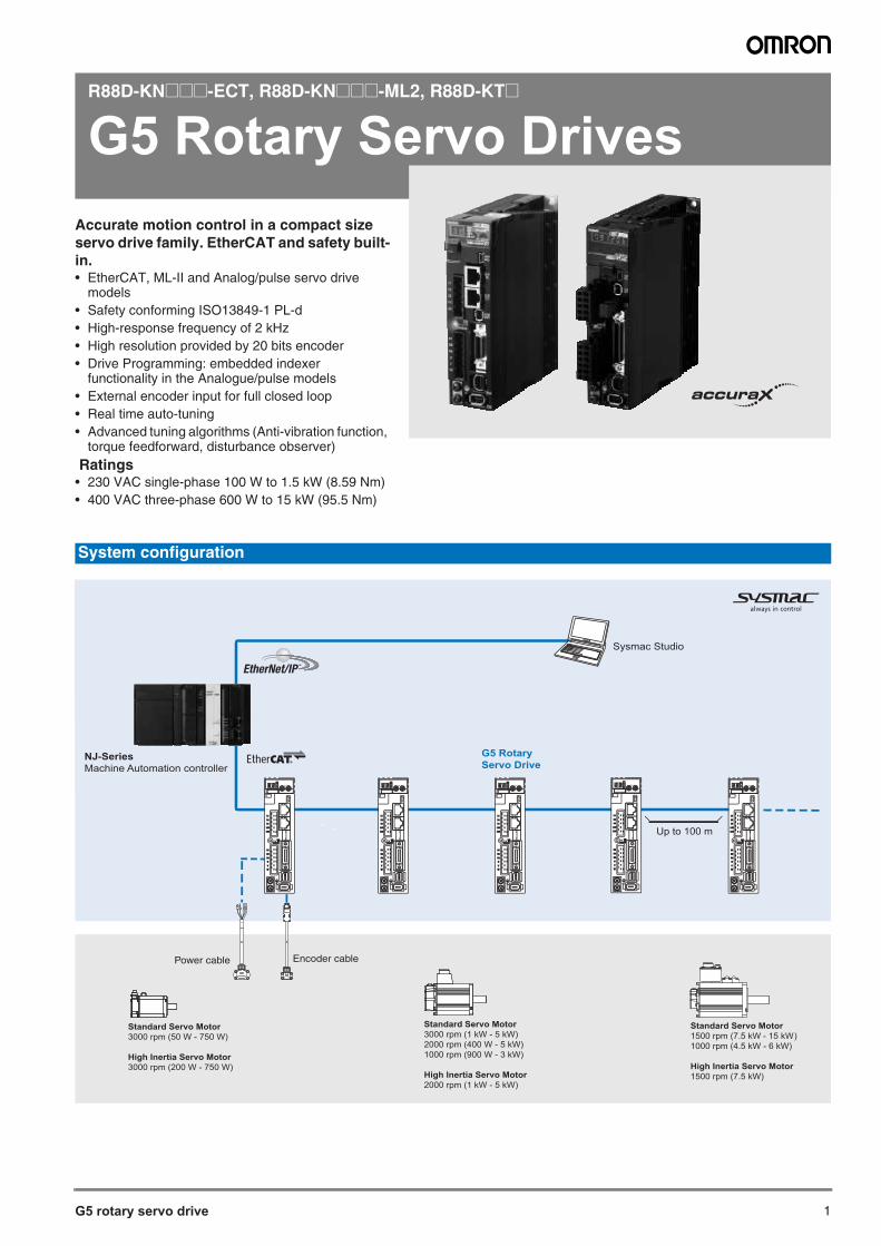
1G5 rotary servo drive
R88D-KN@@@-ECT, R88D-KN@@@-ML2, R88D-KT@
G5 Rotary Servo DrivesAccurate motion control in a compact size servo drive family. EtherCAT and safety built-in.• EtherCAT, ML-II and Analog/pulse servo drive
models• Safety conforming ISO13849-1 PL-d• High-response frequency of 2 kHz• High resolution provided by 20 bits encoder• Drive Programming: embedded indexer
functionality in the Analogue/pulse models• External encoder input for full closed loop• Real time auto-tuning• Advanced tuning algorithms (Anti-vibration function,
torque feedforward, disturbance observer) Ratings• 230 VAC single-phase 100 W to 1.5 kW (8.59 Nm)• 400 VAC three-phase 600 W to 15 kW (95.5 Nm)
System configuration
G5 RotaryServo Drive
Up to 100 m
ADR ADR ADR ADR
Encoder cablePower cable
Standard Servo Motor 3000 rpm (1 kW - 5 kW) 2000 rpm (400 W - 5 kW)1000 rpm (900 W - 3 kW)
High Inertia Servo Motor2000 rpm (1 kW - 5 kW)
Standard Servo Motor 3000 rpm (50 W - 750 W)
High Inertia Servo Motor3000 rpm (200 W - 750 W)
Standard Servo Motor1500 rpm (7.5 kW - 15 kW)1000 rpm (4.5 kW - 6 kW)
High Inertia Servo Motor1500 rpm (7.5 kW)
NJ-SeriesMachine Automation controller
ADR
Sysmac Studio

G5 rotary servo drive 3
Servo drive
Single-phase, 230 V
Three-phase, 400 V
Type designation
Servo drive specifications
Servo drive type R88D-K@ 01H@ 02H@ 04H@ 08H@ 10H@ 15H@Applicable servo motor
R88M-K@ 05030(H/T)-@ 20030(H/T)-@ 40030(H/T)-@ 75030(H/T)-@ 1K020(H/T)-@ 1K030(H/T)-@10030(H/T)-@ – – – – 1K530(H/T)-@
– – – – – 1K520(H/T)-@– – – – – 90010(H/T)-@
Bas
ic s
peci
ficat
ions
Max. applicable motor capacity W
100 200 400 750 1000 1500
Continuous output current Arms
1.2 1.6 2.6 4.1 5.9 9.4
Input power Main circuit Single-phase/3-phase, 200 to 240 VAC +10 to –15% (50/60 Hz)Supply Control circuit Single-phase, 200 to 240 VAC +10 to –15% (50/60 Hz)Control method IGBT-driven PWM method, sinusoidal driveFeedback Serial encoder (incremental/absolute value)
Con
ditio
ns Usage/storage temperature 0 to +55°C/–20 to 65°CUsage/storage humidity 90% RH or less (non-condensing)Altitude 1000m or less above sea levelVibration/shock resistance (max.) 5.88 m/s2 10 to 60 Hz (Continuous operation at resonance point is not allowed) / 19.6 m/s2
Configuration Base mounted Approx. weight kg 0.8 1.1 1.6 1.8
Servo drive type R88D-K@ 06F@ 10F@ 15F@ 20F@ 30F@ 50F@ 75F@ 150F@Applicable servo motor
R88M-K@ 40020(F/C)-@ 75030(F/C)-@ 1K030(F/C)-@ 2K030(F/C)-@ 3K030(F/C)-@ 4K030(F/C)-@ 6K010C-@ 11K015C-@60020(F/C)-@ 1K020(F/C)-@ 1K530(F/C)-@ 2K020(F/C)-@ 3K020(F/C)-@ 5K030(F/C)-@ 7K515C-@ 15K015C-@
– – 1K520(F/C)-@ – 2K010(F/C)-@ 4K020(F/C)-@ – –– – 90010(F/C)-@ – – 5K020(F/C)-@ – –– – – – – 4K510C-@ – –– – – – – 3K010(F/C)-@ – –
Bas
ic s
peci
ficat
ions
Max. applicable motor capacity kW 0.6 1.0 1.5 2.0 3.0 5.0 7.5 15.0Continuous output current Arms 1.5 2.9 4.7 6.7 9.4 16.5 22.0 33.4Input power Main circuit 3-phase, 380 to 480 VAC +10 to –15% (50/60Hz) Supply Control circuit 24 VDC ±15%Control method IGBT-driven PWM method, sinusoidal driveFeedback Serial encoder Incremental or absolute encoder Absolute encoder
Con
ditio
ns
Usage/storage temperature 0 to 55°C/–20 to 65°CUsage/storage humidity 90% RH or less (non-condensing)Altitude 1000 m or less above sea levelVibration/shock resistance 5.88 m/s2 10 to 60 Hz (Continuous operation at resonance point is not allowed)/19.6 m/s2
Configuration Base mountedApprox. weight kg 1.9 2.7 4.7 13.5 21.0
G5 Series servo drive
R88D-KN01H-ECT
Drive TypeT: Analog/pulse type
N: Network type Voltage Code
230 V
Output
100 W
400 V
01H02H
04H08H10H
15H06F10F15F20F30F
400 W200 W
750 W
1 kW1.5 kW
600 W
1.0 kW1.5 kW
2.0 kW3.0 kW5.0 kW7.5 kW15.0 kW
ModelBlank: Analog/pulse type
ECT: EtherCAT comms
Capacity and Voltage
50F75F150F
4 AC servo systems
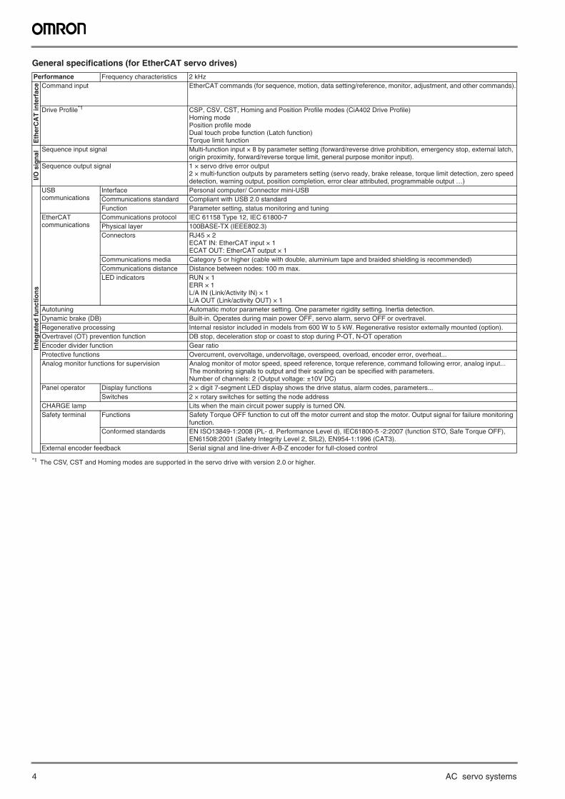
General specifications (for EtherCAT servo drives)
Performance Frequency characteristics 2 kHz
Eth
erC
AT
inte
rfac
e Command input EtherCAT commands (for sequence, motion, data setting/reference, monitor, adjustment, and other commands).
Drive Profile*1
*1 The CSV, CST and Homing modes are supported in the servo drive with version 2.0 or higher.
CSP, CSV, CST, Homing and Position Profile modes (CiA402 Drive Profile)Homing modePosition profile modeDual touch probe function (Latch function)Torque limit function
I/O s
ign
al
Sequence input signal Multi-function input × 8 by parameter setting (forward/reverse drive prohibition, emergency stop, external latch, origin proximity, forward/reverse torque limit, general purpose monitor input).
Sequence output signal 1 × servo drive error output2 × multi-function outputs by parameters setting (servo ready, brake release, torque limit detection, zero speed detection, warning output, position completion, error clear attributed, programmable output …)
Inte
gra
ted
fu
nct
ion
s
USBcommunications
Interface Personal computer/ Connector mini-USBCommunications standard Compliant with USB 2.0 standardFunction Parameter setting, status monitoring and tuning
EtherCATcommunications
Communications protocol IEC 61158 Type 12, IEC 61800-7Physical layer 100BASE-TX (IEEE802.3)Connectors RJ45 × 2
ECAT IN: EtherCAT input × 1ECAT OUT: EtherCAT output × 1
Communications media Category 5 or higher (cable with double, aluminium tape and braided shielding is recommended)Communications distance Distance between nodes: 100 m max.LED indicators RUN × 1
ERR × 1L/A IN (Link/Activity IN) × 1L/A OUT (Link/activity OUT) × 1
Autotuning Automatic motor parameter setting. One parameter rigidity setting. Inertia detection.Dynamic brake (DB) Built-in. Operates during main power OFF, servo alarm, servo OFF or overtravel.Regenerative processing Internal resistor included in models from 600 W to 5 kW. Regenerative resistor externally mounted (option).Overtravel (OT) prevention function DB stop, deceleration stop or coast to stop during P-OT, N-OT operationEncoder divider function Gear ratioProtective functions Overcurrent, overvoltage, undervoltage, overspeed, overload, encoder error, overheat...Analog monitor functions for supervision Analog monitor of motor speed, speed reference, torque reference, command following error, analog input...
The monitoring signals to output and their scaling can be specified with parameters.Number of channels: 2 (Output voltage: ±10V DC)
Panel operator Display functions 2 × digit 7-segment LED display shows the drive status, alarm codes, parameters...Switches 2 × rotary switches for setting the node address
CHARGE lamp Lits when the main circuit power supply is turned ON.Safety terminal Functions Safety Torque OFF function to cut off the motor current and stop the motor. Output signal for failure monitoring
function.Conformed standards EN ISO13849-1:2008 (PL- d, Performance Level d), IEC61800-5 -2:2007 (function STO, Safe Torque OFF),
EN61508:2001 (Safety Integrity Level 2, SIL2), EN954-1:1996 (CAT3).External encoder feedback Serial signal and line-driver A-B-Z encoder for full-closed control
G5 rotary servo drive 5
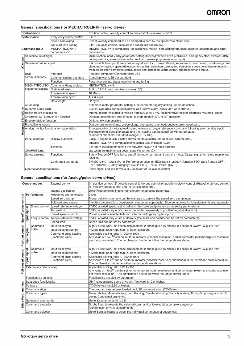
General specifications (for MECHATROLINK-II servo drives)
General specifications (for Analog/pulse servo drives)
Control mode Position control, velocity control, torque control, full-closed control.Performance Frequency characteristics 2 kHz
Speed zero clamp Preset velocity command can be clamped to zero by the speed zero clamp input.soft start time setting 0 to 10 s (acceleration, deceleration can be set separately).
Command input MECHATROLINK-IIcommunication
MECHATROLINK-II commands (for sequence, motion, data setting/reference, monitor, adjustment and other commands)
I/O s
ign
al
Sequence input signal Multi-function input × 8 by parameter setting (forward/reverse drive prohibition, emergency stop, external latch, origin proximity, forward/reverse torque limit, general purpose monitor input).
Sequence output signal It is possible to output three types of signal form incl.: brake release, servo ready, servo alarm, positioning com-plete, motor rotation speed detection, torque limit detection, zero speed detection, speed coincidence detection, warning, position command status, speed limit detection, alarm output, speed command status.
Inte
gra
ted
fu
nct
ion
s
USBcommunications
Interface Personal computer/ Connector mini-USBCommunications standard Compliant with USB 2.0 standardFunction Parameter setting, status monitoring and tuning
MECHATROLINK-II communications
Communications protocol MECHATROLINK-IIStation address 41H to 51 FH (max. number of slaves: 30)Transmission speed 10 MbpsTransmission cycle 1, 2 & 4 msData length 32 bytes
Autotuning Automatic motor parameter setting. One parameter rigidity setting. Inertia detection.Dynamic brake (DB) Built-in. Operates during main power OFF, servo alarm, servo OFF or overtravel.Regenerative processing Internal resistor included in models from 600 W to 5 kW. Regenerative resistor externally mounted (option).Overtravel (OT) prevention function DB stop, deceleration stop or coast to stop during P-OT, N-OT operationEncoder divider function Optional division possibleProtective functions Overcurrent, overvoltage, undervoltage, overspeed, overload, encoder error, overheat...Analog monitor functions for supervision Analog monitor of motor speed, speed reference, torque reference, command following error, analog input...
The monitoring signals to output and their scaling can be specified with parameters.Number of channels: 2 (Output voltage: ±10V DC)
Panel operator Display functions 2-digit 7-segment LED display shows the drive status, alarm codes, parameters...MECHATROLINK-II communications status LED indicator (COM)
Switches 2 × rotary switches for setting the MECHATROLINK-II node addressCHARGE lamp Lits when the main circuit power supply is turned ON.Safety terminal Functions Safety Torque OFF function to cut off the motor current and stop the motor. Output signal for failure monitoring
function.Conformed standards EN ISO13849-1:2008 (PL- d, Performance Level d), IEC61800-5 -2:2007 (function STO, Safe Torque OFF),
EN61508:2001 (Safety Integrity Level 2, SIL2), EN954-1:1996 (CAT3).External encoder feedback Serial signal and line-driver A-B-Z encoder for full-closed control
Control modes External control (1) position control, (2) velocity control, (3) torque control, (4) position/velocity control, (5) position/torque control, (6) velocity/torque control and (7) full-closed control.
Internal positioning Drive Programming: indexer functionality enabled by parameter.
Sp
eed
/to
rqu
e co
ntr
ol Performance Frequency characteristics 2 kHz
Speed zero clamp Preset velocity command can be clamped to zero by the speed zero clamp input.Soft start time setting 0 to 10 s (acceleration, deceleration can be set separately). S-curve acceleration/deceleration is also available.
Inp
ut
sig
nal
Speed control Speed reference voltage 6 VDC at rated speed: set at delivery (the scale and polarity can be set by parameters)Torque limit 3 VDC at rated torque (torque can be limited separately in positive/negative direction).Preset speed control Preset speed is selectable from 8 internal settings by digital inputs.
Torque control Torque reference voltage 3 VDC at rated torque: set at delivery (the scale and polarity can be set by parameters).Speed limit Speed limit can be set by parameter.
Po
siti
on
co
ntr
ol
Inp
ut s
ign
al Command
pulseInput pulse type Sign + pulse train, 90° phase displacement 2-phase pulse (A-phase+ B-phase) or CCW/CW pulse trainInput pulse frequency 4 Mpps max. (200 Kpps max. at open collector).Command pulse scaling(Electronic Gear)
Applicable scaling ratio: 1/1000 to 1000Any value of 1 to 230 can be set for numerator (encoder resolution) and denominator (command pulse resolution per motor revolution). The combination has to be within the range shown above.
Fu
ll-cl
ose
d c
on
tro
l
Inp
ut
sig
nal Command
pulseInput pulse type Sign + pulse train, 90° phase displacement 2-phase pulse (A-phase+ B-phase) or CCW/CW pulse trainInput pulse frequency 4 Mpps max. (200 Kpps max. at open collector).Command pulse scaling(Electronic Gear)
Applicable scaling ratio: 1/1000 to 1000Any value of 1 to 230 can be set for numerator (encoder resolution) and denominator (command pulse resolution). The combination has to be within the range shown above.
External encoder scaling Applicable scaling ratio: 1/20 to 160Any value of 1 to 230 can be set for numerator (encoder resolution) and denominator (external encoder resolution per motor revolution). The combination has to be within the range shown above.
Dri
ve P
rog
ram
min
g
Functionality selection Functionality enabled by parameter.Supported functionality G5 Analogue/pulse servo drive with firmware 1.10 or higher.Software CX-Drive version 2.30 or higher.Communication The program can be downloaded via USB communication (CX-Drive)Command types Move relative, Move absolute, Jog, Homing, Deceleration stop, Velocity update, Timer, Output signal control,
Jump, Conditional branching, Number of commands Up to 32 commands (0 to 31)Command execution Strobe input to execute the selected command or to execute a complex sequence
(combination of various commands).Command selection Up to 5 digital inputs to select the individual commands or sequences
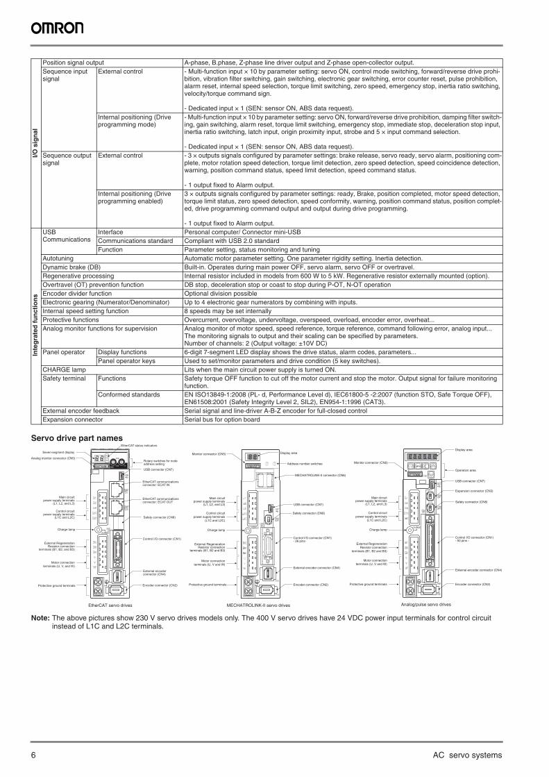
6 AC servo systems
Servo drive part names
Note: The above pictures show 230 V servo drives models only. The 400 V servo drives have 24 VDC power input terminals for control circuit instead of L1C and L2C terminals.
I/O s
ign
al
Position signal output A-phase, B.phase, Z-phase line driver output and Z-phase open-collector output.Sequence input signal
External control - Multi-function input × 10 by parameter setting: servo ON, control mode switching, forward/reverse drive prohi-bition, vibration filter switching, gain switching, electronic gear switching, error counter reset, pulse prohibition, alarm reset, internal speed selection, torque limit switching, zero speed, emergency stop, inertia ratio switching, velocity/torque command sign.
- Dedicated input × 1 (SEN: sensor ON, ABS data request).Internal positioning (Drive programming mode)
- Multi-function input × 10 by parameter setting: servo ON, forward/reverse drive prohibition, damping filter switch-ing, gain switching, alarm reset, torque limit switching, emergency stop, immediate stop, deceleration stop input, inertia ratio switching, latch input, origin proximity input, strobe and 5 × input command selection.
- Dedicated input × 1 (SEN: sensor ON, ABS data request).Sequence output signal
External control - 3 × outputs signals configured by parameter settings: brake release, servo ready, servo alarm, positioning com-plete, motor rotation speed detection, torque limit detection, zero speed detection, speed coincidence detection, warning, position command status, speed limit detection, speed command status.
- 1 output fixed to Alarm output.Internal positioning (Drive programming enabled)
3 × outputs signals configured by parameter settings: ready, Brake, position completed, motor speed detection, torque limit status, zero speed detection, speed conformity, warning, position command status, position complet-ed, drive programming command output and output during drive programming.
- 1 output fixed to Alarm output.
Inte
gra
ted
fu
nct
ion
s
USBCommunications
Interface Personal computer/ Connector mini-USBCommunications standard Compliant with USB 2.0 standardFunction Parameter setting, status monitoring and tuning
Autotuning Automatic motor parameter setting. One parameter rigidity setting. Inertia detection.Dynamic brake (DB) Built-in. Operates during main power OFF, servo alarm, servo OFF or overtravel.Regenerative processing Internal resistor included in models from 600 W to 5 kW. Regenerative resistor externally mounted (option).Overtravel (OT) prevention function DB stop, deceleration stop or coast to stop during P-OT, N-OT operationEncoder divider function Optional division possibleElectronic gearing (Numerator/Denominator) Up to 4 electronic gear numerators by combining with inputs.Internal speed setting function 8 speeds may be set internallyProtective functions Overcurrent, overvoltage, undervoltage, overspeed, overload, encoder error, overheat...Analog monitor functions for supervision Analog monitor of motor speed, speed reference, torque reference, command following error, analog input...
The monitoring signals to output and their scaling can be specified by parameters.Number of channels: 2 (Output voltage: ±10V DC)
Panel operator Display functions 6-digit 7-segment LED display shows the drive status, alarm codes, parameters...Panel operator keys Used to set/monitor parameters and drive condition (5 key switches).
CHARGE lamp Lits when the main circuit power supply is turned ON.Safety terminal Functions Safety torque OFF function to cut off the motor current and stop the motor. Output signal for failure monitoring
function.Conformed standards EN ISO13849-1:2008 (PL- d, Performance Level d), IEC61800-5 -2:2007 (function STO, Safe Torque OFF),
EN61508:2001 (Safety Integrity Level 2, SIL2), EN954-1:1996 (CAT3). External encoder feedback Serial signal and line-driver A-B-Z encoder for full-closed controlExpansion connector Serial bus for option board
USB connector (CN7)
Analog monitor connector (CN5)
Protective ground terminals
Control I/O connector (CN1)
Safety connector (CN8)
Encoder connector (CN2)
Charge lamp
ADR
Seven-segment display
EtherCAT status indicators
Monitor connector (CN5)
Encoder connector (CN2)
MECHATROLINK-II connector (CN6)
Monitor connector (CN5)
Encoder connector (CN2)
MECHATROLINK-II servo drives Analog/pulse servo drivesEtherCAT servo drives
Main circuitpower supply terminals
(L1, L2, and L3)
Control circuitpower supply terminals
(L1C and L2C)
External RegenerationResistor connection
terminals (B1, B2, and B3)
Motor connectionterminals (U, V, and W)
Rotary switches for nodeaddress setting
EtherCAT communicationsconnector: ECAT IN
EtherCAT communicationsconnector: ECAT OUT
External encoderconnector (CN4)
Main circuitpower supply terminals
(L1, L2, and L3)
Control circuitpower supply terminals
(L1C and L2C)
Charge lamp
External RegenerationResistor connection
terminals (B1, B2 and B3)
Motor connectionterminals (U, V and W)
Protective ground terminals
Display area
Address number switches
USB connector (CN7)
Safety connector (CN8)
Control I/O connector (CN1)- 26 pins-
External encoder connector (CN4)
Main circuitpower supply terminals
(L1, L2, and L3)
Control circuitpower supply terminals
(L1C and L2C)
Charge lamp
External RegenerationResistor connection
terminals (B1, B2 and B3)
Motor connectionterminals (U, V and W)
Protective ground terminals
Display area
Operation area
USB connector (CN7)
Expansion connector (CN3)
Safety connector (CN8)
Control I/O connector (CN1)- 50 pins -
External encoder connector (CN4)
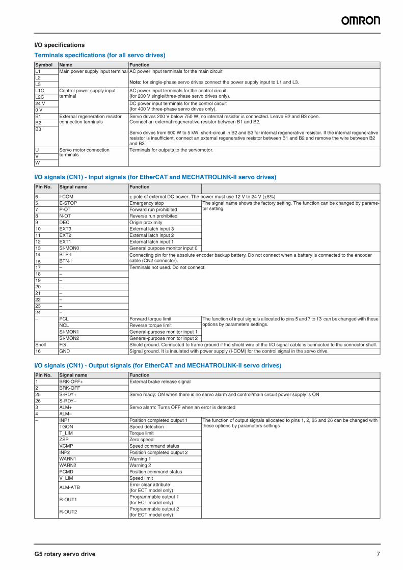
G5 rotary servo drive 7
I/O specifications
Terminals specifications (for all servo drives)
I/O signals (CN1) - Input signals (for EtherCAT and MECHATROLINK-II servo drives)
I/O signals (CN1) - Output signals (for EtherCAT and MECHATROLINK-II servo drives)
Symbol Name FunctionL1 Main power supply input terminal AC power input terminals for the main circuit
Note: for single-phase servo drives connect the power supply input to L1 and L3.L2L3L1C Control power supply input
terminalAC power input terminals for the control circuit(for 200 V single/three-phase servo drives only).L2C
24 V DC power input terminals for the control circuit(for 400 V three-phase servo drives only).0 V
B1 External regeneration resistor connection terminals
Servo drives 200 V below 750 W: no internal resistor is connected. Leave B2 and B3 open.Connect an external regenerative resistor between B1 and B2.
Servo drives from 600 W to 5 kW: short-circuit in B2 and B3 for internal regenerative resistor. If the internal regenerative resistor is insufficient, connect an external regenerative resistor between B1 and B2 and remove the wire between B2 and B3.
B2B3
U Servo motor connection terminals
Terminals for outputs to the servomotor.VW
Pin No. Signal name Function
6 I-COM ± pole of external DC power. The power must use 12 V to 24 V (±5%)5 E-STOP Emergency stop The signal name shows the factory setting. The function can be changed by parame-
ter setting.7 P-OT Forward run prohibited 8 N-OT Reverse run prohibited 9 DEC Origin proximity10 EXT3 External latch input 311 EXT2 External latch input 2 12 EXT1 External latch input 1 13 SI-MON0 General purpose monitor input 0 14 BTP-I Connecting pin for the absolute encoder backup battery. Do not connect when a battery is connected to the encoder
cable (CN2 connector).15 BTN-I17 – Terminals not used. Do not connect.18 –19 –20 –21 –22 –23 –24 –– PCL Forward torque limit The function of input signals allocated to pins 5 and 7 to 13 can be changed with these
options by parameters settings.NCL Reverse torque limitSI-MON1 General-purpose monitor input 1SI-MON2 General-purpose monitor input 2
Shell FG Shield ground. Connected to frame ground if the shield wire of the I/O signal cable is connected to the connector shell.16 GND Signal ground. It is insulated with power supply (I-COM) for the control signal in the servo drive.
Pin No. Signal name Function1 BRK-OFF+ External brake release signal2 BRK-OFF25 S-RDY+ Servo ready: ON when there is no servo alarm and control/main circuit power supply is ON 26 S-RDY–3 ALM+ Servo alarm: Turns OFF when an error is detected 4 ALM–– INP1 Position completed output 1 The function of output signals allocated to pins 1, 2, 25 and 26 can be changed with
these options by parameters settingsTGON Speed detectionT_LIM Torque limitZSP Zero speedVCMP Speed command statusINP2 Position completed output 2WARN1 Warning 1WARN2 Warning 2PCMD Position command statusV_LIM Speed limit
ALM-ATBError clear attribute(for ECT model only)
R-OUT1Programmable output 1(for ECT model only)
R-OUT2Programmable output 2(for ECT model only)
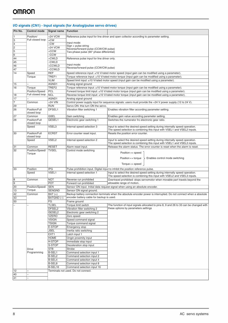
8 AC servo systems
I/O signals (CN1) - Input signals (for Analog/pulse servo drives)
Pin No. Control mode Signal name Function
1 Position/Full closed loop
+24 VCW Reference pulse input for line driver and open collector according to parameter setting.
Input mode:Sign + pulse stringReverse/forward pulse (CCW/CW pulse)Two-phase pulse (90° phase differential)
3 +CW4 –CW2 +24 VCW5 +CCW6 –CCW44 +CWLD Reference pulse input for line driver only.
Input mode:Reverse/forward pulse (CCW/CW pulse)
45 –CWLD46 +CCWLD47 –CCWLD14 Speed REF Speed reference input: ±10 V/rated motor speed (input gain can be modified using a parameter).
Torque TREF1 Torque reference input: ±10 V/rated motor torque (input gain can be modified using a parameter).VLIM Speed limit input: ±10 V/rated motor speed (input gain can be modified using a parameter).
15 – AGND1 Analog signal ground16 Torque TREF2 Torque reference input: ±10 V/rated motor torque (input gain can be modified using a parameter).
Position/SpeedFull closed loop
PCL Forward torque limit input: ±10 V/rated motor torque (input gain can be modified using a parameter).18 NCL Reverse torque limit input: ±10 V/rated motor torque (input gain can be modified using a parameter).17 – AGND1 Analog signal ground7 Common +24 VIN Control power supply input for sequence signals: users must provide the +24 V power supply (12 to 24 V).29 RUN Servo ON: this turn ON the servo.26 Position/Full
closed loopDFSEL1 Vibration filter switching 1 Enables vibration filter according parameter setting.
27 Common GSEL Gain switching Enables gain value according parameter setting.28 Position/Full
closed loopGESEL1 Electronic gear switching 1 Switches the numerator fro electronic gear ratio.
Speed VSEL3 Internal speed selection 3 Input to select the desired speed setting during internally speed operation.The speed selection is combining this input with VSEL1 and VSEL2 inputs.
30 Position/Full closed loop
ECRST Error counter reset input. Resets the position error counter.
Speed VSEL2 Internal speed selection 2 Input to select the desired speed setting during internally speed operation.The speed selection is combining this input with VSEL1 and VSEL3 inputs.
31 Common RESET Alarm reset input. Release the alarm status. The error counter is reset when the alarm is reset.32 Position/Speed/
TorqueTVSEL Control mode switching
33 Position IPG Pulse prohibition input. Digital input to inhibit the position reference pulse.Speed VSEL1 Internal speed selection 1 Input to select the desired speed setting during internally speed operation.
The speed selection is combining this input with VSEL2 and VSEL3 inputs.8 Common NOT Reverse run prohibited Overtravel prohibited: stops servomotor when movable part travels beyond the
allowable range of motion.9 POT Forward run prohibited20 Position/Speed/
TorqueSEN Sensor ON input. Initial data request signal when using an absolute encoder.
13 SENGND Sensor ON signal ground.42 Common BAT (+) Backup battery connection terminals when the absolute encoder power is interrupted. Do not connect when a absolute
encoder battery cable for backup is used.43 BATGND (–)50 FG Frame ground– – TLSEL Torque limit switch The function of input signals allocated to pins 8, 9 and 26 to 33 can be changed with
these options by parameters settingsDFSEL2 Vibration filter switching 2GESEL2 Electronic gear switching 2VZERO Zero speedVSIGN Speed command signalTSIGN Torque command signalE-STOP Emergency stopJSEL Inertia ratio switching
Drive Programming
EXT1 Latch input 1HOME Origin proximity inputH-STOP Immediate stop inputS-STOP Deceleration stop inputSTB StrobeB-SEL1 Command selection input 1B-SEL2 Command selection input 2B-SEL4 Command selection input 4B-SEL8 Command selection input 8B-SEL16 Command selection input 16
12 – Terminals not used. Do not connect.40 –41 –
Position speed
Position torque
Torque speed
Enables control mode switching
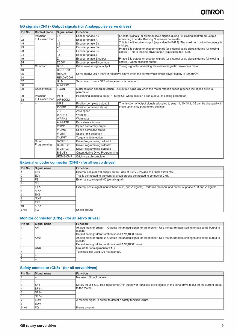
G5 rotary servo drive 9
I/O signals (CN1) - Output signals (for Analog/pulse servo drives)
External encoder connector (CN4) - (for all servo drives)
Monitor connector (CN5) - (for all servo drives)
Safety connector (CN8) - (for all servo drives)
Pin No. Control mode Signal name Function21 Position/
Full closed loop+A Encoder phase A+ Encoder signals (or external scale signals during full closing control) are output
according Encoder Dividing Numerator parameter.This is the line-driver output (equivalent to R422). The maximum output frequency is 4 Mbps.Phase Z is output for encoder signals (or external scale signals during full closing control). This is the line-driver output (equivalent to R422).
22 –A Encoder phase A–48 +B Encoder phase B+49 –B Encoder phase B–23 +Z Encoder phase Z+24 –Z Encoder phase Z–19 Z Encoder phase-Z output Phase Z is output for encoder signals (or external scale signals during full closing
control). Open-collector output.25 ZCOM Encoder phase-Z common11 Common BKIR Brake release signal output Timing signal for operating the electromagnetic brake on a motor.10 BKIRCOM35 READY Servo ready: ON if there is not servo alarm when the control/main circuit power supply is turned ON.34 READYCOM37 /ALM Servo alarm: turns OFF when an error is detected.36 ALMCOM39 Speed/torque TGON Motor rotation speed detection. This output turns ON when the motor rotation speed reaches the speed set in a
parameter.39 Position/
Full closed loopINP1 Positioning complete output 1: turns ON when position error is equal to setting parameter.
38 INP1COM– – INP2 Position complete output 2 The function of output signals allocated to pins 11, 10, 34 to 39 can be changed with
these options by parameters settings.P-CMD Position command statusZSP Zero speedWARN1 Warning 1WARN2 Warning 2ALM-ATB Error clear attributeVCMP Speed conformity outputV-CMD Speed command statusV-LIMIT Speed limit detectionT-LIMIT Torque limit detection
Drive Programming
B-CTRL1 Drive Programming output 1B-CTRL2 Drive Programming output 2B-CTRL3 Drive Programming output 3B-BUSY Output during Drive ProgrammingHOME-CMP Origin search complete
Pin No. Signal name Function1 E5V External scale power supply output. Use at 5.2 V ±5% and at or below 250 mA.2 E0V This is connected to the control circuit ground connected to connector CN1.3 PS External scale signal I/O (serial signal).4 /PS5 EXA External scale signal input (Phase A, B, and Z signals). Performs the input and output of phase A, B and Z signals.6 /EXA7 EXB8 /EXB9 EXZ10 /EXZShell FG Shield ground
Pin No. Signal name Function1 AM1 Analog monitor output 1. Outputs the analog signal for the monitor. Use the parameters setting to select the output to
monitor.Default setting: Motor rotation speed 1 V/(1000 r/min).
2 AM2 Analog monitor output 2. Outputs the analog signal for the monitor. Use the parameters setting to select the output to monitor.Default setting: Motor rotation speed 1 V/(1000 r/min).
3 GND Ground for analog monitors 1, 2.4 – Terminals not used. Do not connect.5 –6 –
Pin No. Signal name Function1 – Not used. Do not connect2 –3 SF1– Safety input 1 & 2. This input turns OFF the power transistor drive signals in the servo drive to cut off the current output
to the motor.4 SF1+5 SF2–6 SF2+7 EDM– A monitor signal is output to detect a safety function failure.8 EDM+Shell FG Frame ground.
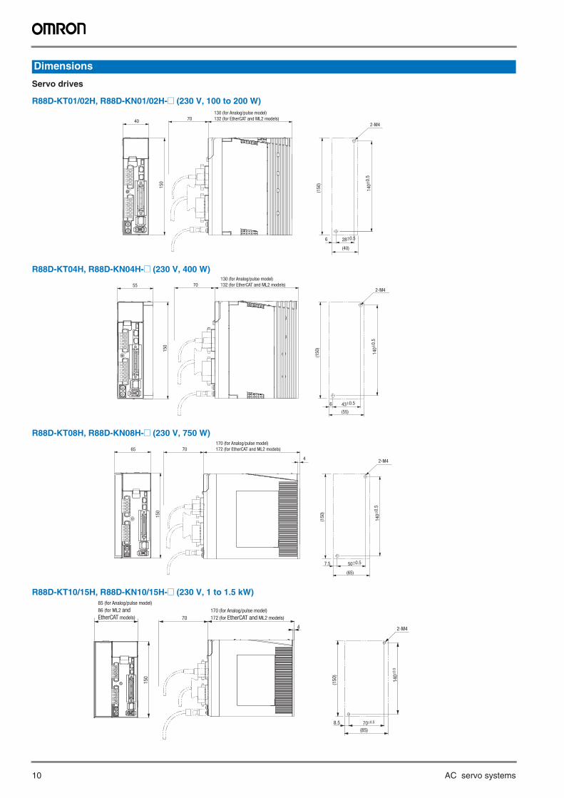
10 AC servo systems
Servo drives
R88D-KT01/02H, R88D-KN01/02H-@ (230 V, 100 to 200 W)
R88D-KT04H, R88D-KN04H-@ (230 V, 400 W)
R88D-KT08H, R88D-KN08H-@ (230 V, 750 W)
R88D-KT10/15H, R88D-KN10/15H-@ (230 V, 1 to 1.5 kW)
Dimensions
130 (for Analog/pulse model)
132 (for EtherCAT and ML2 models)7040
15
0
(40)
28±0.56
(15
0)
14
0±0
.5
2-M4
55
15
0
(15
0)
43±0.56
(55)
14
0±0
.5
702-M4
130 (for Analog/pulse model)
132 (for EtherCAT and ML2 models)
4
65
150
(150)
140±0
.5
50±0.57.5
(65)
70
2-M4
170 (for Analog/pulse model)
172 (for EtherCAT and ML2 models)
15
0
4 2-M4
14
0±0
.5
(15
0)
70±0.58.5
(85)
70
170 (for Analog/pulse model)
172 (for EtherCAT and ML2 models)
85 (for Analog/pulse model)
86 (for ML2 and
EtherCAT models)
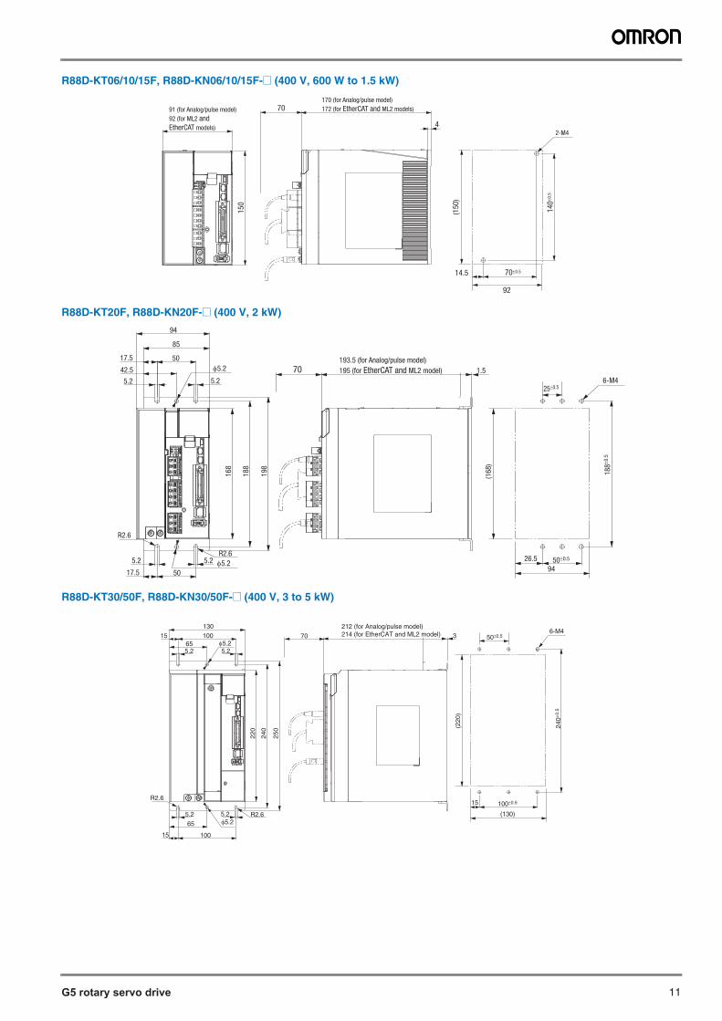
G5 rotary servo drive 11
R88D-KT06/10/15F, R88D-KN06/10/15F-@ (400 V, 600 W to 1.5 kW)
R88D-KT20F, R88D-KN20F-@ (400 V, 2 kW)
R88D-KT30/50F, R88D-KN30/50F-@ (400 V, 3 to 5 kW)
15
0
4
(15
0)
14
0±0
.5
70±0.514.5
70
2-M4
170 (for Analog/pulse model)
172 (for EtherCAT and ML2 models)91 (for Analog/pulse model)
92 (for ML2 and
EtherCAT models)
92
φ5.2
R2.6
R2.6
φ5.2
25±0.5
18
8±0
.5
50±0.5
94
(16
8)
1.5
94
85
5017.5
42.5
5.2 5.2
5.2 5.2
5017.5
16
8
18
8
19
8
706-M4
193.5 (for Analog/pulse model)
195 (for EtherCAT and ML2 model)
26.5
φ5.2
R2.6φ5.2
R2.6
100
5.25.265
15
15130100
655.2 5.2
220
240
250
50±0.5
240±
0.5
(220
)
(130)
100±0.515
212 (for Analog/pulse model)214 (for EtherCAT and ML2 model) 370
6-M4
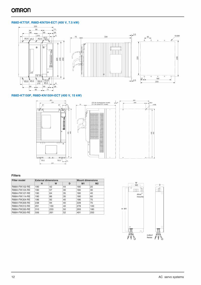
12 AC servo systems
R88D-KT75F, R88D-KN75H-ECT (400 V, 7.5 kW)
R88D-KT150F, R88D-KN150H-ECT (400 V, 15 kW)
Filters
Filter model External dimensions Mount dimensionsH W D M1 M2
R88A-FIK102-RE 190 42 44 180 20R88A-FIK104-RE 190 57 30 180 30R88A-FIK107-RE 190 64 35 180 40R88A-FIK114-RE 190 86 35 180 60R88A-FIK304-RE 196 92 40 186 70R88A-FIK306-RE 238 94 40 228 70R88A-FIK312-RE 291 130 40 278 100R88A-FIK330-RE 310 233 50 293 180R88A-FIK350-RE 506 261 52 491 200
250
235
220
9090
9071
26210 11
21090
9090
712611
233
334 3.5
R2.6 R2.6 R2.6φ5.2
φ5.2
φ5.2φ5.2
R2.6 R2.6 R2.6
70
2.5
10-M4
235
45
220
27 180233
261231
31
450
7.5
435
31231
4270 (for Analog/pulse model)271 (for EtherCAT model)
R3.5 R3.5
φ7φ7 70
261
450
435
200 30.54-M6
H
WD
drivemounts
M1
M2
outputflexes
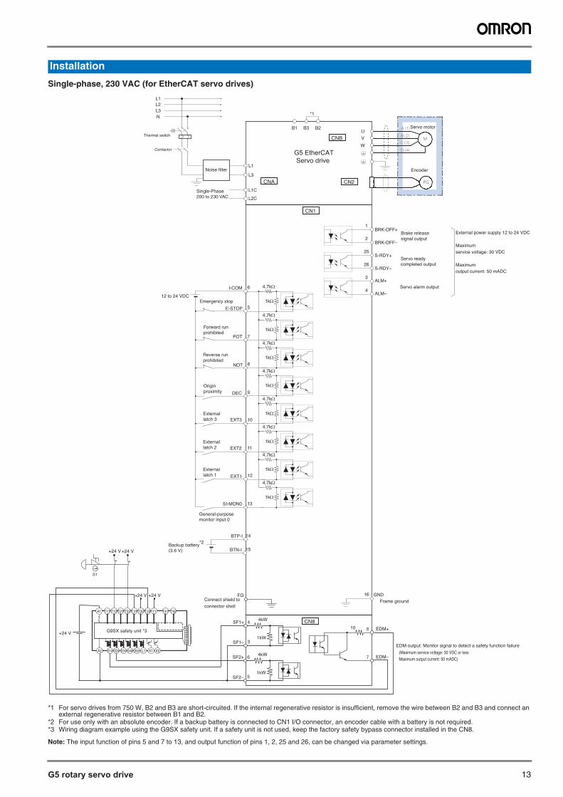
G5 rotary servo drive 13
*1 For servo drives from 750 W, B2 and B3 are short-circuited. If the internal regenerative resistor is insufficient, remove the wire between B2 and B3 and connect an external regenerative resistor between B1 and B2.
*2 For use only with an absolute encoder. If a backup battery is connected to CN1 I/O connector, an encoder cable with a battery is not required.*3 Wiring diagram example using the G9SX safety unit. If a safety unit is not used, keep the factory safety bypass connector installed in the CN8.
Note: The input function of pins 5 and 7 to 13, and output function of pins 1, 2, 25 and 26, can be changed via parameter settings.
Installation
Single-phase, 230 VAC (for EtherCAT servo drives)
S14A2 S24 S34 S44 S54 L1 X1 X2
T11A1 T12 T21 T22 T31 T32 T33 Y1 T41 T42
G9SX safety unit *3
G5 EtherCAT Servo drive
Encoder
Servo motorB3 B2U
V
W
B1
L1
L3Noise filter
L1C
L2C
Single-Phase 200 to 230 VAC
Contactor
L1L2L3N
Thermal switch
CN1
*1
Emergency stop
BRK-OFF+
Servo alarm output
BRK-OFF–
1
2
S-RDY+
S-RDY–
ALM–
25
26
ALM+3
4
12
11
10
9
8
7
5
6I-COM
External latch 1
External latch 2
External latch 3
Origin proximity
Reverse run prohibited
Forward run prohibited
12 to 24 VDC
External power supply 12 to 24 VDC
Maximum service voltage: 30 VDC
Maximum output current: 50 mADC
13
General-purposemonitor input 0
Frame groundGND16
BTP-I
BTN-I Backup battery*2
(3.6 V)
14
15
(Maximum service voltage: 30 VDC or less Maximum output current: 50 mADC)
Connect shield toconnector shell
SF1+
SF1–
4
31kW
4kW
8 EDM+
EDM–
FG
7
10
SF2+
SF2–
6
51kW
4kW
CN8
+24 V
EDM output: Monitor signal to detect a safety function failure
S1
+24 V +24 V
+24 V +24 V
POT
E-STOP
NOT
DEC
EXT3
EXT2
EXT1
SI-MON0
Brake release signal output
Servo ready completed output
4.7kΩ
1kΩ
4.7kΩ
1kΩ
4.7kΩ
1kΩ
4.7kΩ
1kΩ
4.7kΩ
1kΩ
4.7kΩ
1kΩ
4.7kΩ
1kΩ
4.7kΩ
1kΩ
CNB
CNA CN2
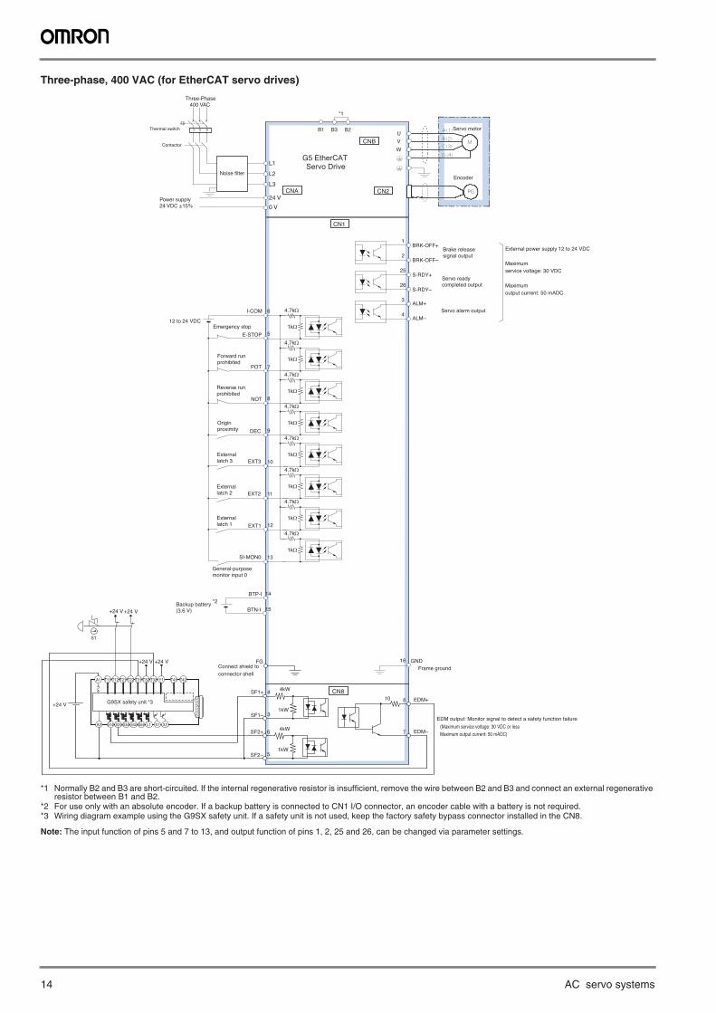
14 AC servo systems
Three-phase, 400 VAC (for EtherCAT servo drives)
*1 Normally B2 and B3 are short-circuited. If the internal regenerative resistor is insufficient, remove the wire between B2 and B3 and connect an external regenerative resistor between B1 and B2.
*2 For use only with an absolute encoder. If a backup battery is connected to CN1 I/O connector, an encoder cable with a battery is not required.*3 Wiring diagram example using the G9SX safety unit. If a safety unit is not used, keep the factory safety bypass connector installed in the CN8.
Note: The input function of pins 5 and 7 to 13, and output function of pins 1, 2, 25 and 26, can be changed via parameter settings.
S14A2 S24 S34 S44 S54 L1 X1 X2
T11A1 T12 T21 T22 T31 T32 T33 Y1 T41 T42
G9SX safety unit *3
G5 EtherCATServo Drive
Encoder
Servo motorB3 B2U
V
W
B1
CN1
*1
BRK-OFF+
Servo alarm output
BRK-OFF–
1
2
S-RDY+
S-RDY–
ALM–
25
26
ALM+3
4
12
11
10
9
8
7
5
6I-COM
12 to 24 VDC
External power supply 12 to 24 VDC
Maximum service voltage: 30 VDC
Maximum output current: 50 mADC
13
Frame groundGND16
BTP-I
BTN-I Backup battery *2
(3.6 V)
14
15
(Maximum service voltage: 30 VDC or less Maximum output current: 50 mADC)
Connect shield toconnector shell
SF1+
SF1–
4
31kW
4kW
8 EDM+
EDM–
FG
7
10
SF2+
SF2–
6
51kW
4kW
CN8
+24 V
EDM output: Monitor signal to detect a safety function failure
S1
+24 V +24 V
+24 V +24 V
Brake release signal output
Servo ready completed output
4.7kΩ
1kΩ
4.7kΩ
1kΩ
4.7kΩ
1kΩ
4.7kΩ
1kΩ
4.7kΩ
1kΩ
4.7kΩ
1kΩ
4.7kΩ
1kΩ
4.7kΩ
1kΩ
CNB
CNA CN2
L1
L2
24 V
0 V
Noise filter
Power supply24 VDC ±15%
Contactor
Thermal switch
Three-Phase 400 VAC
L3
Emergency stop
External latch 1
External latch 2
External latch 3
Origin proximity
Reverse run prohibited
Forward run prohibited
General-purposemonitor input 0
POT
E-STOP
NOT
DEC
EXT3
EXT2
EXT1
SI-MON0
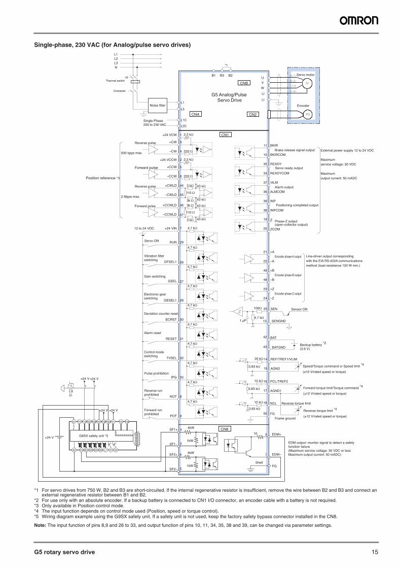
G5 rotary servo drive 15
Single-phase, 230 VAC (for Analog/pulse servo drives)
*1 For servo drives from 750 W, B2 and B3 are short-circuited. If the internal regenerative resistor is insufficient, remove the wire between B2 and B3 and connect an external regenerative resistor between B1 and B2.
*2 For use only with an absolute encoder. If a backup battery is connected to CN1 I/O connector, an encoder cable with a battery is not required.*3 Only available in Position control mode.*4 The input function depends on control mode used (Position, speed or torque control).*5 Wiring diagram example using the G9SX safety unit. If a safety unit is not used, keep the factory safety bypass connector installed in the CN8.
Note: The input function of pins 8,9 and 26 to 33, and output function of pins 10, 11, 34, 35, 38 and 39, can be changed via parameter settings.
S14A2 S24 S34 S44 S54 L1 X1 X2
T11A1 T12 T21 T22 T31 T32 T33 Y1 T41 T42
G9SX safety unit *5
G5 Analog/PulseServo Drive
Encoder
Servo motorB3 B2U
V
W
B1
L1
L3
L1C
L2C
Noise filter
Single-Phase 200 to 230 VAC
Contactor
L1L2L3N
Thermal switch
CN1
*1
3 kΩ
110 Ω
43 kΩ
3k Ω
220 Ω
5
2
6
Servo ON
44
45
+CW
–CW
+CCW
–CCW
+CWLD
–CWLD
Reverse pulse
Forward pulse
BKIRBrake release signal output
Alarm output
BKIRCOM
11
10
READY
READYCOM
ALMCOM
35
34
/ALM37
36
INPCOM
INP39
38
32TVSEL
31RESET
30ECRST
28GESEL1
27GSEL
26DFSEL1
29RUN
7+24 VIN
Control mode switching
Alarm reset
Deviation counter reset
Electronic gear switching
Gain switching
Vibration filter switching
12 to 24 VDC
External power supply 12 to 24 VDC
Maximum service voltage: 30 VDC
Maximum output current: 50 mADC
Reverse pulse
46
47
110 Ω
43 kΩ
33IPGPulse prohibition
500 kpps max.
2 Mpps max.
8NOT
Reverse run prohibited
9POT
Forward run prohibited
ZCOM
Z Phase-Z output (open-collector output)
1810 kΩ
3.83 kΩ
PCL/TREF2
NCL
AGND1
Reverse torque limit
3.83 kΩ
16
17
10 kΩ
19
25
Frame groundFG50
4.7 kΩ
4.7 kΩ
4.7 kΩ
4.7 kΩ
43 kΩ
3 kΩ
+CCWLD
–CCWLD
Forward pulse
+AEncoder phase-A output
Encoder phase-B output
Encoder phase-Z output
21
–A22
+B49
–B48
+Z23
–Z24
Line-driver output corresponding with the EIA RS-422A communications method (load resistance 120 W min.)
220 Ω
3
1
4
43 kΩ
3k Ω
4.7 kΩ
4.7 kΩ
4.7 kΩ
4.7 kΩ
4.7 kΩ
4.7 kΩ
+24 VCW 2.2 kΩ
+24 VCCW 2.2 kΩ
20100Ω
4.7 kΩ1 μF
SEN
SENGND13
Sensor ON
BAT
BATGNDBackup battery *2
(3.6 V)
42
43
Position reference *3
REF/TREF1/VLIM
AGND3.83 kΩ
14
15
20 kΩ
Forward torque limit/Torque command *4
(±12 V/rated speed or torque)
Reverse torque limit *4
(±12 V/rated speed or torque)
Speed/Torque command or Speed limit *4
(±10 V/rated speed or torque)
Shell
SF1+
SF1–
4
31kW
4kW
8 EDM+
EDM–
FG
7
10
SF2+
SF2–
6
51kW
4kW
CN8
+24 V
S1
+24 V +24 V
+24 V +24 V
CNB
CNA CN2
EDM output: monitor signal to detect a safetyfunction failure(Maximum service voltage: 30 VDC or lessMaximum output current: 50 mADC)
Servo ready output
Positioning completed output

16 AC servo systems
Three-phase, 400 VAC (for Analog/pulse servo drives)
*1 Normally B2 and B3 are short-circuited. If the internal regenerative resistor is insufficient, remove the wire between B2 and B3 and connect an external regenerative resistor between B1 and B2.
*2 For use only with an absolute encoder. If a backup battery is connected to CN1 I/O connector, an encoder cable with a battery is not required.*3 Only available in Position control mode.*4 The input function depends on control mode used (Position, speed or torque control).*5 Wiring diagram example using the G9SX safety unit. If a safety unit is not used, keep the factory safety bypass connector installed in the CN8.
Note: The input function of pins 8,9 and 26 to 33, and output function of pins 10, 11, 34, 35, 38 and 39, can be changed via parameter settings.
S14A2 S24 S34 S44 S54 L1 X1 X2
T11A1 T12 T21 T22 T31 T32 T33 Y1 T41 T42
G9SX safety unit *5
G5 Analog/PulseServo Drive
Encoder
Servo motorB3 B2U
V
W
B1
CN1
*1
3 kΩ
110 Ω
43 kΩ
3k Ω
220 Ω
5
2
6
Servo ON
44
45
+CW
–CW
+CCW
–CCW
+CWLD
–CWLD
Reverse pulse
Forward pulse
BKIRBrake release signal output
Alarm output
BKIRCOM
11
10
READY
READYCOM
ALMCOM
35
34
/ALM37
36
INPCOM
INP39
38
32TVSEL
31RESET
30ECRST
28GESEL1
27GSEL
26DFSEL1
29RUN
7+24 VIN
Control mode switching
Alarm reset
Deviation counter reset
Electronic gear switching
Gain switching
Vibration filter switching
12 to 24 VDC
External power supply 12 to 24 VDC
Maximum service voltage: 30 VDC
Maximum output current: 50 mADC
Reverse pulse
46
47
110 Ω
43 kΩ
33IPGPulse prohibition
500 kpps max.
2 Mpps max.
8NOT
Reverse run prohibited
9POT
Forward run prohibited
ZCOM
Z Phase-Z output (open-collector output)
1810 kΩ
3.83 kΩ
PCL/TREF2
NCL
AGND13.83 kΩ
16
17
10 kΩ
19
25
Frame groundFG50
4.7 kΩ
4.7 kΩ
4.7 kΩ
4.7 kΩ
43 kΩ
3 kΩ
+CCWLD
–CCWLD
Forward pulse
+AEncoder phase-A output
Encoder phase-B output
Encoder phase-Z output
21
–A22
+B49
–B48
+Z23
–Z24
Line-driver output corresponding with the EIA RS-422A communications method (load resistance 120 W min.)
220 Ω
3
1
4
43 kΩ
3k Ω
4.7 kΩ
4.7 kΩ
4.7 kΩ
4.7 kΩ
4.7 kΩ
4.7 kΩ
+24 VCW 2.2 kΩ
+24 VCCW 2.2 kΩ
20100Ω
4.7 kΩ1 μF
SEN
SENGND13
Sensor ON
BAT
BATGNDBackup battery *2
(3.6 V)
42
43
Position reference *3
REF/TREF1/VLIM
AGND3.83 kΩ
14
15
20 kΩ
Forward torque limit/Torque command *4
(±12 V/rated speed or torque)
Reverse torque limit*4
(±12 V/rated speed or torque)
Speed/Torque command or Speed limit *4
(±10 V/rated speed or torque)
Shell
SF1+
SF1–
4
31kW
4kW
8 EDM+
EDM–
FG
7
10
SF2+
SF2–
6
51kW
4kW
CN8
+24 V
S1
+24 V +24 V
+24 V +24 V
L1
L2
24 V
0 V
Noise filter
Power supply24 VDC ±15%
Contactor
Thermal switch
Three-Phase 400 VAC
L3
CNB
CNA CN2
Servo ready output
Positioning completed output
EDM output: monitor signal to detect a safetyfunction failure(Maximum service voltage: 30 VDC or lessMaximum output current: 50 mADC)
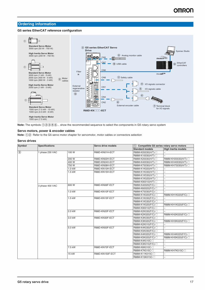
G5 rotary servo drive 17
Note: The symbols ABCDE... show the recommended sequence to select the components in G5 rotary servo system
Servo motors, power & encoder cablesNote: AB Refer to the G5 servo motor chapter for servomotor, motor cables or connectors selection
Servo drives
Ordering information
G5 series EtherCAT reference configuration
Symbol Specifications Servo drive models A Compatible G5 series rotary servo motors Standard models High Inertia models
C 1 phase 230 VAC 100 W R88D-KN01H-ECT R88M-K05030(H/T)-@ –R88M-K10030(H/T)-@ –
200 W R88D-KN02H-ECT R88M-K20030(H/T)-@ R88M-KH20030(H/T)-@400 W R88D-KN04H-ECT R88M-K40030(H/T)-@ R88M-KH40030(H/T)-@750 W R88D-KN08H-ECT R88M-K75030(H/T)-@ R88M-KH75030(H/T)[email protected] kW R88D-KN10H-ECT R88M-K1K020(H/T)-@ –1.5 kW R88D-KN15H-ECT R88M-K1K030(H/T)-@ –
R88M-K1K530(H/T)-@ –R88M-K1K520(H/T)-@ –R88M-K90010(H/T)-@ –
3 phase 400 VAC 600 W R88D-KN06F-ECT R88M-K40020(F/C)-@ –R88M-K60020(F/C)-@ –
1.0 kW R88D-KN10F-ECT R88M-K75030(F/C)-@ –R88M-K1K020(F/C)-@ R88M-KH1K020(F/C)-@
1.5 kW R88D-KN15F-ECT R88M-K1K030(F/C)-@ –R88M-K1K530(F/C)-@ –R88M-K1K520(F/C)-@ R88M-KH1K520(F/C)-@R88M-K90010(F/C)-@ –
2.0 kW R88D-KN20F-ECT R88M-K2K030(F/C)-@ –R88M-K2K020(F/C)-@ R88M-KH2K020(F/C)-@
3.0 kW R88D-KN30F-ECT R88M-K3K030(F/C)-@ –R88M-K3K020(F/C)-@ R88M-KH3K020(F/C)-@R88M-K2K010(F/C)-@ –
5.0 kW R88D-KN50F-ECT R88M-K4K030(F/C)-@ –R88M-K5K030(F/C)-@ –R88M-K4K020(F/C)-@ R88M-KH4K020(F/C)-@R88M-K5K020(F/C)-@ R88M-KH5K020(F/C)-@R88M-K4K510C-@ –R88M-K3K010(F/C)-@ –
7.5 kW R88D-KN75F-ECT R88M-K6K010C-@ –R88M-K7K515C-@ R88M-KH7K515C-@
15 kW R88D-KN150F-ECT R88M-K11K015C-@ –R88M-K15K015C-@ –
CN6
CN1
G5 series EtherCAT Servo Drive
Motorcables
B
C
Terminal block for I/O signals
I/O signals cable
I
J
Filter
D
Analog monitor cableCN5
CN7USB cable
K
External regenerative resistor
CN2
CN4
CN8
ADR
I/O signals connector
Safety cable
External encoder cable
E
F
G
H
M
N
A
Standard Servo Motor 3000 rpm (1 kW - 5 kW) 2000 rpm (400 W - 5 kW)1000 rpm (900 W - 3 kW)
High Inertia Servo Motor2000 rpm (1 kW - 5 kW)
A
Standard Servo Motor 3000 rpm (50 W - 750 W)
High Inertia Servo Motor3000 rpm (200 W - 750 W)
A
Standard Servo Motor1500 rpm (7.5 kW - 15 kW)1000 rpm (4.5 kW - 6 kW)
High Inertia Servo Motor1500 rpm (7.5 kW)
EtherCAT controllers L
Sysmac Studio
R88D-KN@@@-ECT
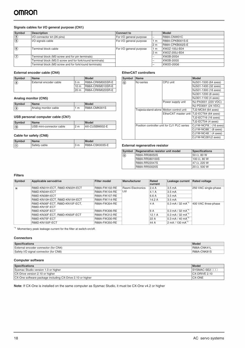
18 AC servo systems
Signals cables for I/O general purpose (CN1)
External encoder cable (CN4)
Analog monitor (CN5)
USB personal computer cable (CN7)
Cable for safety (CN8)
EtherCAT controllers
External regenerative resistor
Filters
Connectors
Computer software
Note: If CX-One is installed on the same computer as Sysmac Studio, it must be CX-One v4.2 or higher
Symbol Description Connect to ModelD I/O connector kit (26 pins) For I/O general purpose – R88A-CNW01CE I/O signals cable For I/O general purpose 1 m R88A-CPKB001S-E
2 m R88A-CPKB002S-EF Terminal block cable For I/O general purpose 1 m XW2Z-100J-B34
2 m XW2Z-200J-B34G Terminal block (M3 screw and for pin terminals) – XW2B-20G4
Terminal block (M3.5 screw and for fork/round terminals) – XW2B-20G5Terminal block (M3 screw and for fork/round terminals) – XW2D-20G6
Symbol Name Model
H External encoder cable 5 m R88A-CRKM005SR-E10 m R88A-CRKM010SR-E20 m R88A-CRKM020SR-E
Symbol Name Model
I Analog monitor cable 1 m R88A-CMK001S
Symbol Name Model
J USB mini-connector cable 2 m AX-CUSBM002-E
Symbol Name Model
K Safety cable 3 m R88A-CSK003S-E
Symbol Name Model
L NJ-series CPU unit NJ501-1500 (64 axes)NJ501-1400 (32 axes)NJ501-1300 (16 axes)NJ301-1200 (8 axes)NJ301-1100 (4 axes)
Power supply unit NJ-PA3001 (220 VDC)NJ-PD3001 (24 VDC)
Trajexia stand-alone Motion control unit TJ2-MC64 (64 axes)EtherCAT master unit TJ2-ECT64 (64 axes)
TJ2-ECT16 (16 axes)TJ2-ECT04 (4 axes)
Position controller unit for CJ1 PLC series CJ1W-NCF8@ (16 axes)CJ1W-NC88@ (8 axes)CJ1W-NC48@ (4 axes)CJ1W-NC281(2 axes)
Symbol Regenerative resistor unit model Specifications
M R88A-RR08050S 50 , 80 WR88A-RR080100S 100 , 80 WR88A-RR22047S 47 , 220 WR88A-RR50020S 20 , 500 W
Symbol Applicable servodrive Filter model Manufacturer Rated current
Leakage current Rated voltage
N R88D-KN01H-ECT, R88D-KN02H-ECT R88A-FIK102-RE Rasmi Electronics Ltd
2.4 A 3.5 mA 250 VAC single-phaseR88D-KN04H-ECT R88A-FIK104-RE 4.1 A 3.5 mAR88D-KN08H-ECT R88A-FIK107-RE 6.6 A 3.5 mAR88D-KN10H-ECT, R88D-KN15H-ECT R88A-FIK114-RE 14.2 A 3.5 mAR88D-KN06F-ECT, R88D-KN10F-ECT, R88D-KN15F-ECT
R88A-FIK304-RE 4 A 0.3 mA / 32 mA*1
*1 Momentary peak leakage current for the filter at switch-on/off.
400 VAC three-phase
R88D-KN20F-ECT R88A-FIK306-RE 6 A 0.3 mA / 32 mA*1
R88D-KN30F-ECT, R88D-KN50F-ECT R88A-FIK312-RE 12.1 A 0.3 mA / 32 mA*1
R88D-KN75F-ECT R88A-FIK330-RE 22 A 0.3 mA / 40 mA*1
R88D-KN150F-ECT R88A-FIK350-RE 44 A 2 mA / 130 mA*1
Specifications ModelExternal encoder connector (for CN4) R88A-CNK41LSafety I/O signal connector (for CN8) R88A-CNK81S
Specifications ModelSysmac Studio version 1.0 or higher SYSMAC-SE2@@@CX-Drive version 2.10 or higher CX-DRIVE 2.10CX-One software package including CX-Drive 2.10 or higher CX-ONE
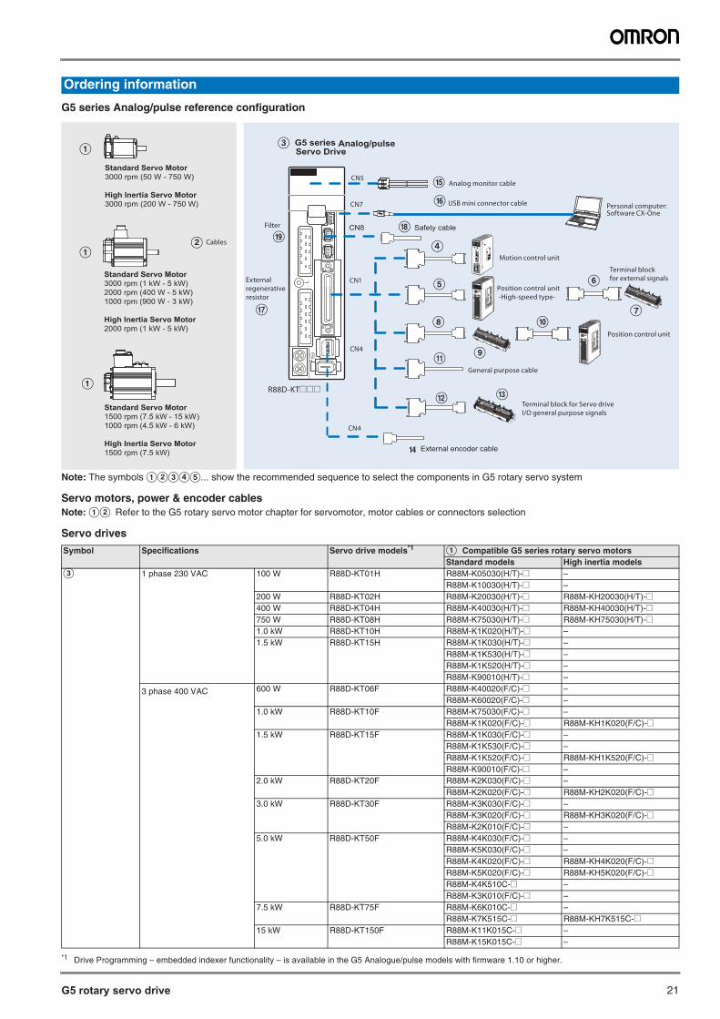
G5 rotary servo drive 21
Note: The symbols ABCDE... show the recommended sequence to select the components in G5 rotary servo system
Servo motors, power & encoder cablesNote: AB Refer to the G5 rotary servo motor chapter for servomotor, motor cables or connectors selection
Servo drives
Ordering information
G5 series Analog/pulse reference configuration
Symbol Specifications Servo drive models*1
*1 Drive Programming – embedded indexer functionality – is available in the G5 Analogue/pulse models with firmware 1.10 or higher.
A Compatible G5 series rotary servo motorsStandard models High inertia models
C 1 phase 230 VAC 100 W R88D-KT01H R88M-K05030(H/T)-@ –R88M-K10030(H/T)-@ –
200 W R88D-KT02H R88M-K20030(H/T)-@ R88M-KH20030(H/T)-@400 W R88D-KT04H R88M-K40030(H/T)-@ R88M-KH40030(H/T)-@750 W R88D-KT08H R88M-K75030(H/T)-@ R88M-KH75030(H/T)[email protected] kW R88D-KT10H R88M-K1K020(H/T)-@ –1.5 kW R88D-KT15H R88M-K1K030(H/T)-@ –
R88M-K1K530(H/T)-@ –R88M-K1K520(H/T)-@ –R88M-K90010(H/T)-@ –
3 phase 400 VAC 600 W R88D-KT06F R88M-K40020(F/C)-@ –R88M-K60020(F/C)-@ –
1.0 kW R88D-KT10F R88M-K75030(F/C)-@ –R88M-K1K020(F/C)-@ R88M-KH1K020(F/C)-@
1.5 kW R88D-KT15F R88M-K1K030(F/C)-@ –R88M-K1K530(F/C)-@ –R88M-K1K520(F/C)-@ R88M-KH1K520(F/C)-@R88M-K90010(F/C)-@ –
2.0 kW R88D-KT20F R88M-K2K030(F/C)-@ –R88M-K2K020(F/C)-@ R88M-KH2K020(F/C)-@
3.0 kW R88D-KT30F R88M-K3K030(F/C)-@ –R88M-K3K020(F/C)-@ R88M-KH3K020(F/C)-@R88M-K2K010(F/C)-@ –
5.0 kW R88D-KT50F R88M-K4K030(F/C)-@ –R88M-K5K030(F/C)-@ –R88M-K4K020(F/C)-@ R88M-KH4K020(F/C)-@R88M-K5K020(F/C)-@ R88M-KH5K020(F/C)-@R88M-K4K510C-@ –R88M-K3K010(F/C)-@ –
7.5 kW R88D-KT75F R88M-K6K010C-@ –R88M-K7K515C-@ R88M-KH7K515C-@
15 kW R88D-KT150F R88M-K11K015C-@ –R88M-K15K015C-@ –
Personal computer: Software CX-One
CN1
USB mini connector cable
Analog monitor cable
B Cables
C
M
CN4
CN5
CN7
D Motion control unit
Filter
O
P
Terminal block for Servo drive I/O general purpose signals
Position control unit
H J
K
L
E
I
General purpose cable
External regenerative resistor
Q
Position control unit -High-speed type-
S
Terminal block for external signalsF
G
R88D-KT@@@
CN8 Safety cable
CN4
External encoder cable
A
Standard Servo Motor 3000 rpm (1 kW - 5 kW) 2000 rpm (400 W - 5 kW)1000 rpm (900 W - 3 kW)
High Inertia Servo Motor2000 rpm (1 kW - 5 kW)
A
Standard Servo Motor 3000 rpm (50 W - 750 W)
High Inertia Servo Motor3000 rpm (200 W - 750 W)
A
Standard Servo Motor1500 rpm (7.5 kW - 15 kW)1000 rpm (4.5 kW - 6 kW)
High Inertia Servo Motor1500 rpm (7.5 kW) N
R
G5 series Analog/pulse Servo Drive
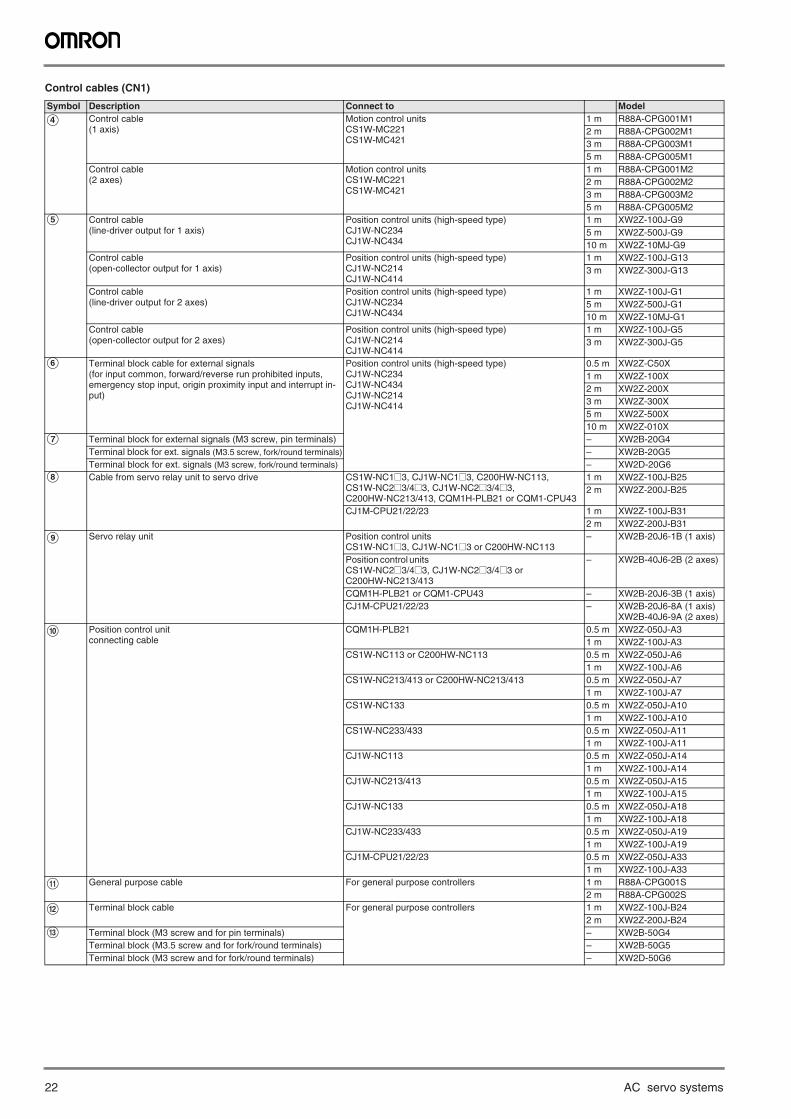
22 AC servo systems
Control cables (CN1)
Symbol Description Connect to Model
D Control cable(1 axis)
Motion control units CS1W-MC221CS1W-MC421
1 m R88A-CPG001M1 2 m R88A-CPG002M13 m R88A-CPG003M15 m R88A-CPG005M1
Control cable(2 axes)
Motion control units CS1W-MC221CS1W-MC421
1 m R88A-CPG001M22 m R88A-CPG002M23 m R88A-CPG003M25 m R88A-CPG005M2
E Control cable(line-driver output for 1 axis)
Position control units (high-speed type)CJ1W-NC234CJ1W-NC434
1 m XW2Z-100J-G95 m XW2Z-500J-G910 m XW2Z-10MJ-G9
Control cable(open-collector output for 1 axis)
Position control units (high-speed type)CJ1W-NC214CJ1W-NC414
1 m XW2Z-100J-G133 m XW2Z-300J-G13
Control cable(line-driver output for 2 axes)
Position control units (high-speed type)CJ1W-NC234CJ1W-NC434
1 m XW2Z-100J-G15 m XW2Z-500J-G110 m XW2Z-10MJ-G1
Control cable(open-collector output for 2 axes)
Position control units (high-speed type)CJ1W-NC214CJ1W-NC414
1 m XW2Z-100J-G53 m XW2Z-300J-G5
F Terminal block cable for external signals (for input common, forward/reverse run prohibited inputs, emergency stop input, origin proximity input and interrupt in-put)
Position control units (high-speed type)CJ1W-NC234CJ1W-NC434CJ1W-NC214CJ1W-NC414
0.5 m XW2Z-C50X1 m XW2Z-100X2 m XW2Z-200X3 m XW2Z-300X5 m XW2Z-500X10 m XW2Z-010X
G Terminal block for external signals (M3 screw, pin terminals) – XW2B-20G4Terminal block for ext. signals (M3.5 screw, fork/round terminals) – XW2B-20G5Terminal block for ext. signals (M3 screw, fork/round terminals) – XW2D-20G6
H Cable from servo relay unit to servo drive CS1W-NC1@3, CJ1W-NC1@3, C200HW-NC113, CS1W-NC2@3/4@3, CJ1W-NC2@3/4@3, C200HW-NC213/413, CQM1H-PLB21 or CQM1-CPU43
1 m XW2Z-100J-B252 m XW2Z-200J-B25
CJ1M-CPU21/22/23 1 m XW2Z-100J-B312 m XW2Z-200J-B31
I Servo relay unit Position control unitsCS1W-NC1@3, CJ1W-NC1@3 or C200HW-NC113
– XW2B-20J6-1B (1 axis)
Position control units CS1W-NC2@3/4@3, CJ1W-NC2@3/4@3 or C200HW-NC213/413
– XW2B-40J6-2B (2 axes)
CQM1H-PLB21 or CQM1-CPU43 – XW2B-20J6-3B (1 axis)CJ1M-CPU21/22/23 – XW2B-20J6-8A (1 axis)
XW2B-40J6-9A (2 axes)
J Position control unit connecting cable
CQM1H-PLB21 0.5 m XW2Z-050J-A31 m XW2Z-100J-A3
CS1W-NC113 or C200HW-NC113 0.5 m XW2Z-050J-A61 m XW2Z-100J-A6
CS1W-NC213/413 or C200HW-NC213/413 0.5 m XW2Z-050J-A71 m XW2Z-100J-A7
CS1W-NC133 0.5 m XW2Z-050J-A101 m XW2Z-100J-A10
CS1W-NC233/433 0.5 m XW2Z-050J-A111 m XW2Z-100J-A11
CJ1W-NC113 0.5 m XW2Z-050J-A141 m XW2Z-100J-A14
CJ1W-NC213/413 0.5 m XW2Z-050J-A151 m XW2Z-100J-A15
CJ1W-NC133 0.5 m XW2Z-050J-A181 m XW2Z-100J-A18
CJ1W-NC233/433 0.5 m XW2Z-050J-A191 m XW2Z-100J-A19
CJ1M-CPU21/22/23 0.5 m XW2Z-050J-A331 m XW2Z-100J-A33
K General purpose cable For general purpose controllers 1 m R88A-CPG001S2 m R88A-CPG002S
L Terminal block cable For general purpose controllers 1 m XW2Z-100J-B242 m XW2Z-200J-B24
M Terminal block (M3 screw and for pin terminals) – XW2B-50G4Terminal block (M3.5 screw and for fork/round terminals) – XW2B-50G5Terminal block (M3 screw and for fork/round terminals) – XW2D-50G6
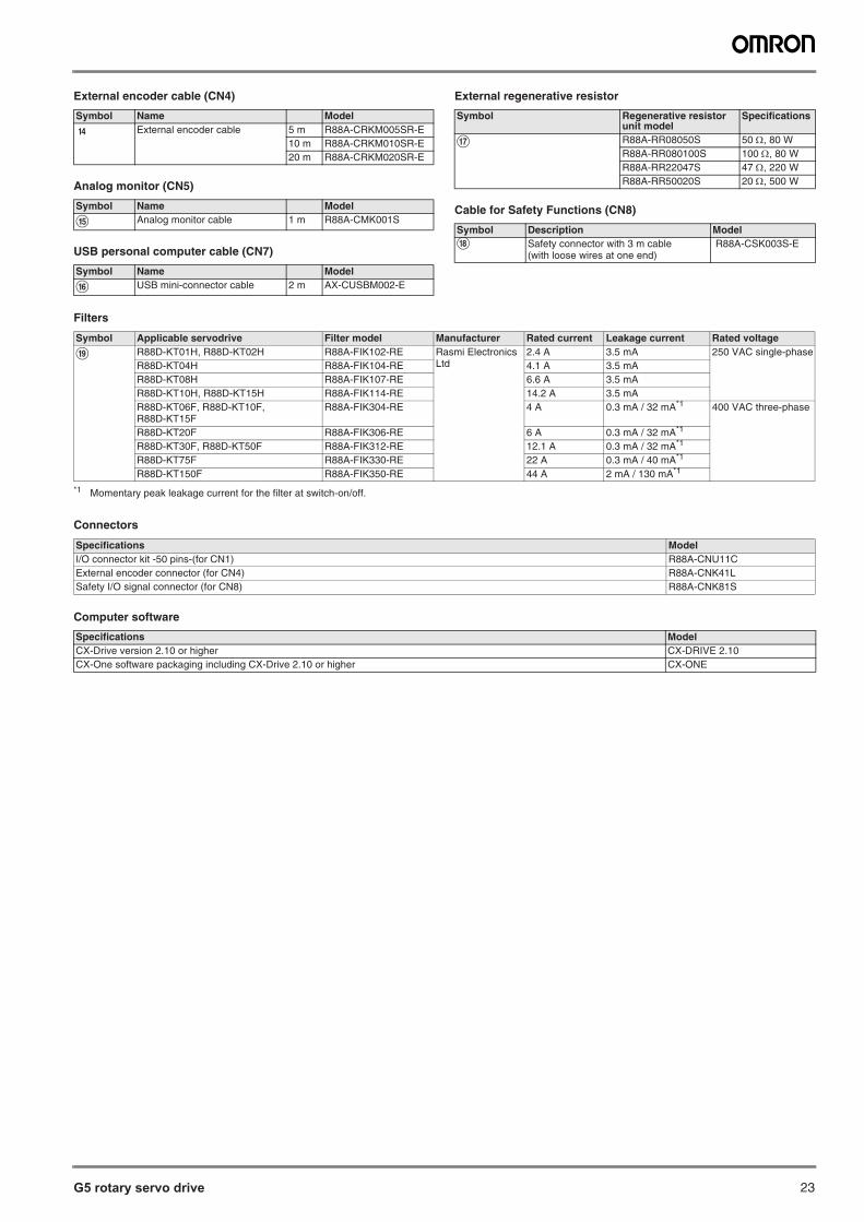
G5 rotary servo drive 23
External encoder cable (CN4)
Analog monitor (CN5)
USB personal computer cable (CN7)
External regenerative resistor
Cable for Safety Functions (CN8)
Filters
Connectors
Computer software
Symbol Name Model
N External encoder cable 5 m R88A-CRKM005SR-E10 m R88A-CRKM010SR-E20 m R88A-CRKM020SR-E
Symbol Name Model
O Analog monitor cable 1 m R88A-CMK001S
Symbol Name Model
P USB mini-connector cable 2 m AX-CUSBM002-E
Symbol Regenerative resistor unit model
Specifications
Q R88A-RR08050S 50 , 80 WR88A-RR080100S 100 , 80 WR88A-RR22047S 47 , 220 WR88A-RR50020S 20 , 500 W
Symbol Description ModelR Safety connector with 3 m cable
(with loose wires at one end) R88A-CSK003S-E
Symbol Applicable servodrive Filter model Manufacturer Rated current Leakage current Rated voltage
S R88D-KT01H, R88D-KT02H R88A-FIK102-RE Rasmi Electronics Ltd
2.4 A 3.5 mA 250 VAC single-phaseR88D-KT04H R88A-FIK104-RE 4.1 A 3.5 mAR88D-KT08H R88A-FIK107-RE 6.6 A 3.5 mAR88D-KT10H, R88D-KT15H R88A-FIK114-RE 14.2 A 3.5 mAR88D-KT06F, R88D-KT10F, R88D-KT15F
R88A-FIK304-RE 4 A 0.3 mA / 32 mA*1
*1 Momentary peak leakage current for the filter at switch-on/off.
400 VAC three-phase
R88D-KT20F R88A-FIK306-RE 6 A 0.3 mA / 32 mA*1
R88D-KT30F, R88D-KT50F R88A-FIK312-RE 12.1 A 0.3 mA / 32 mA*1
R88D-KT75F R88A-FIK330-RE 22 A 0.3 mA / 40 mA*1
R88D-KT150F R88A-FIK350-RE 44 A 2 mA / 130 mA*1
Specifications ModelI/O connector kit -50 pins-(for CN1) R88A-CNU11CExternal encoder connector (for CN4) R88A-CNK41LSafety I/O signal connector (for CN8) R88A-CNK81S
Specifications ModelCX-Drive version 2.10 or higher CX-DRIVE 2.10CX-One software packaging including CX-Drive 2.10 or higher CX-ONE

24 AC servo systems
In the interest of product improvement, specifications are subject to change without notice.
ALL DIMENSIONS SHOWN ARE IN MILLIMETERS.To convert millimeters into inches, multiply by 0.03937. To convert grams into ounces, multiply by 0.03527.
Cat. No. I101E-EN-04A
Terms and Conditions of Sale1. Offer; Acceptance. These terms and conditions (these "Terms") are deemed
part of all quotes, agreements, purchase orders, acknowledgments, price lists,catalogs, manuals, brochures and other documents, whether electronic or inwriting, relating to the sale of products or services (collectively, the "Products")by Omron Electronics LLC and its subsidiary companies (“Omron”). Omronobjects to any terms or conditions proposed in Buyer’s purchase order or otherdocuments which are inconsistent with, or in addition to, these Terms.
2. Prices; Payment Terms. All prices stated are current, subject to change with-out notice by Omron. Omron reserves the right to increase or decrease priceson any unshipped portions of outstanding orders. Payments for Products aredue net 30 days unless otherwise stated in the invoice.
3. Discounts. Cash discounts, if any, will apply only on the net amount of invoicessent to Buyer after deducting transportation charges, taxes and duties, and willbe allowed only if (i) the invoice is paid according to Omron’s payment termsand (ii) Buyer has no past due amounts.
4. Interest. Omron, at its option, may charge Buyer 1-1/2% interest per month orthe maximum legal rate, whichever is less, on any balance not paid within thestated terms.
5. Orders. Omron will accept no order less than $200 net billing. 6. Governmental Approvals. Buyer shall be responsible for, and shall bear all
costs involved in, obtaining any government approvals required for the impor-tation or sale of the Products.
7. Taxes. All taxes, duties and other governmental charges (other than generalreal property and income taxes), including any interest or penalties thereon,imposed directly or indirectly on Omron or required to be collected directly orindirectly by Omron for the manufacture, production, sale, delivery, importa-tion, consumption or use of the Products sold hereunder (including customsduties and sales, excise, use, turnover and license taxes) shall be charged toand remitted by Buyer to Omron.
8. Financial. If the financial position of Buyer at any time becomes unsatisfactoryto Omron, Omron reserves the right to stop shipments or require satisfactorysecurity or payment in advance. If Buyer fails to make payment or otherwisecomply with these Terms or any related agreement, Omron may (without liabil-ity and in addition to other remedies) cancel any unshipped portion of Prod-ucts sold hereunder and stop any Products in transit until Buyer pays allamounts, including amounts payable hereunder, whether or not then due,which are owing to it by Buyer. Buyer shall in any event remain liable for allunpaid accounts.
9. Cancellation; Etc. Orders are not subject to rescheduling or cancellationunless Buyer indemnifies Omron against all related costs or expenses.
10. Force Majeure. Omron shall not be liable for any delay or failure in deliveryresulting from causes beyond its control, including earthquakes, fires, floods,strikes or other labor disputes, shortage of labor or materials, accidents tomachinery, acts of sabotage, riots, delay in or lack of transportation or therequirements of any government authority.
11. Shipping; Delivery. Unless otherwise expressly agreed in writing by Omron:a. Shipments shall be by a carrier selected by Omron; Omron will not drop ship
except in “break down” situations.b. Such carrier shall act as the agent of Buyer and delivery to such carrier shall
constitute delivery to Buyer;c. All sales and shipments of Products shall be FOB shipping point (unless oth-
erwise stated in writing by Omron), at which point title and risk of loss shallpass from Omron to Buyer; provided that Omron shall retain a security inter-est in the Products until the full purchase price is paid;
d. Delivery and shipping dates are estimates only; ande. Omron will package Products as it deems proper for protection against nor-
mal handling and extra charges apply to special conditions.12. Claims. Any claim by Buyer against Omron for shortage or damage to the
Products occurring before delivery to the carrier must be presented in writingto Omron within 30 days of receipt of shipment and include the original trans-portation bill signed by the carrier noting that the carrier received the Productsfrom Omron in the condition claimed.
13. Warranties. (a) Exclusive Warranty. Omron’s exclusive warranty is that theProducts will be free from defects in materials and workmanship for a period oftwelve months from the date of sale by Omron (or such other period expressedin writing by Omron). Omron disclaims all other warranties, express or implied.(b) Limitations. OMRON MAKES NO WARRANTY OR REPRESENTATION,EXPRESS OR IMPLIED, ABOUT NON-INFRINGEMENT, MERCHANTABIL-
ITY OR FITNESS FOR A PARTICULAR PURPOSE OF THE PRODUCTS.BUYER ACKNOWLEDGES THAT IT ALONE HAS DETERMINED THAT THEPRODUCTS WILL SUITABLY MEET THE REQUIREMENTS OF THEIRINTENDED USE. Omron further disclaims all warranties and responsibility ofany type for claims or expenses based on infringement by the Products or oth-erwise of any intellectual property right. (c) Buyer Remedy. Omron’s sole obli-gation hereunder shall be, at Omron’s election, to (i) replace (in the formoriginally shipped with Buyer responsible for labor charges for removal orreplacement thereof) the non-complying Product, (ii) repair the non-complyingProduct, or (iii) repay or credit Buyer an amount equal to the purchase price ofthe non-complying Product; provided that in no event shall Omron be responsi-ble for warranty, repair, indemnity or any other claims or expenses regardingthe Products unless Omron’s analysis confirms that the Products were prop-erly handled, stored, installed and maintained and not subject to contamina-tion, abuse, misuse or inappropriate modification. Return of any Products byBuyer must be approved in writing by Omron before shipment. Omron Compa-nies shall not be liable for the suitability or unsuitability or the results from theuse of Products in combination with any electrical or electronic components,circuits, system assemblies or any other materials or substances or environ-ments. Any advice, recommendations or information given orally or in writing,are not to be construed as an amendment or addition to the above warranty.See http://www.omron247.com or contact your Omron representative for pub-lished information.
14. Limitation on Liability; Etc. OMRON COMPANIES SHALL NOT BE LIABLEFOR SPECIAL, INDIRECT, INCIDENTAL, OR CONSEQUENTIAL DAMAGES,LOSS OF PROFITS OR PRODUCTION OR COMMERCIAL LOSS IN ANYWAY CONNECTED WITH THE PRODUCTS, WHETHER SUCH CLAIM ISBASED IN CONTRACT, WARRANTY, NEGLIGENCE OR STRICT LIABILITY.Further, in no event shall liability of Omron Companies exceed the individualprice of the Product on which liability is asserted.
15. Indemnities. Buyer shall indemnify and hold harmless Omron Companies andtheir employees from and against all liabilities, losses, claims, costs andexpenses (including attorney's fees and expenses) related to any claim, inves-tigation, litigation or proceeding (whether or not Omron is a party) which arisesor is alleged to arise from Buyer's acts or omissions under these Terms or inany way with respect to the Products. Without limiting the foregoing, Buyer (atits own expense) shall indemnify and hold harmless Omron and defend or set-tle any action brought against such Companies to the extent based on a claimthat any Product made to Buyer specifications infringed intellectual propertyrights of another party.
16. Property; Confidentiality. Any intellectual property in the Products is the exclu-sive property of Omron Companies and Buyer shall not attempt to duplicate itin any way without the written permission of Omron. Notwithstanding anycharges to Buyer for engineering or tooling, all engineering and tooling shallremain the exclusive property of Omron. All information and materials suppliedby Omron to Buyer relating to the Products are confidential and proprietary,and Buyer shall limit distribution thereof to its trusted employees and strictlyprevent disclosure to any third party.
17. Export Controls. Buyer shall comply with all applicable laws, regulations andlicenses regarding (i) export of products or information; (iii) sale of products to“forbidden” or other proscribed persons; and (ii) disclosure to non-citizens ofregulated technology or information.
18. Miscellaneous. (a) Waiver. No failure or delay by Omron in exercising any rightand no course of dealing between Buyer and Omron shall operate as a waiverof rights by Omron. (b) Assignment. Buyer may not assign its rights hereunderwithout Omron's written consent. (c) Law. These Terms are governed by thelaw of the jurisdiction of the home office of the Omron company from whichBuyer is purchasing the Products (without regard to conflict of law princi-ples). (d) Amendment. These Terms constitute the entire agreement betweenBuyer and Omron relating to the Products, and no provision may be changedor waived unless in writing signed by the parties. (e) Severability. If any provi-sion hereof is rendered ineffective or invalid, such provision shall not invalidateany other provision. (f) Setoff. Buyer shall have no right to set off any amountsagainst the amount owing in respect of this invoice. (g) Definitions. As usedherein, “including” means “including without limitation”; and “Omron Compa-nies” (or similar words) mean Omron Corporation and any direct or indirectsubsidiary or affiliate thereof.
Certain Precautions on Specifications and Use1. Suitability of Use. Omron Companies shall not be responsible for conformity
with any standards, codes or regulations which apply to the combination of theProduct in the Buyer’s application or use of the Product. At Buyer’s request,Omron will provide applicable third party certification documents identifyingratings and limitations of use which apply to the Product. This information byitself is not sufficient for a complete determination of the suitability of the Prod-uct in combination with the end product, machine, system, or other applicationor use. Buyer shall be solely responsible for determining appropriateness ofthe particular Product with respect to Buyer’s application, product or system.Buyer shall take application responsibility in all cases but the following is anon-exhaustive list of applications for which particular attention must be given:(i) Outdoor use, uses involving potential chemical contamination or electricalinterference, or conditions or uses not described in this document.(ii) Use in consumer products or any use in significant quantities. (iii) Energy control systems, combustion systems, railroad systems, aviationsystems, medical equipment, amusement machines, vehicles, safety equip-ment, and installations subject to separate industry or government regulations. (iv) Systems, machines and equipment that could present a risk to life or prop-erty. Please know and observe all prohibitions of use applicable to this Prod-uct. NEVER USE THE PRODUCT FOR AN APPLICATION INVOLVING SERIOUSRISK TO LIFE OR PROPERTY OR IN LARGE QUANTITIES WITHOUTENSURING THAT THE SYSTEM AS A WHOLE HAS BEEN DESIGNED TO
ADDRESS THE RISKS, AND THAT THE OMRON’S PRODUCT IS PROP-ERLY RATED AND INSTALLED FOR THE INTENDED USE WITHIN THEOVERALL EQUIPMENT OR SYSTEM.
2. Programmable Products. Omron Companies shall not be responsible for theuser’s programming of a programmable Product, or any consequence thereof.
3. Performance Data. Data presented in Omron Company websites, catalogsand other materials is provided as a guide for the user in determining suitabil-ity and does not constitute a warranty. It may represent the result of Omron’stest conditions, and the user must correlate it to actual application require-ments. Actual performance is subject to the Omron’s Warranty and Limitationsof Liability.
4. Change in Specifications. Product specifications and accessories may bechanged at any time based on improvements and other reasons. It is our prac-tice to change part numbers when published ratings or features are changed,or when significant construction changes are made. However, some specifica-tions of the Product may be changed without any notice. When in doubt, spe-cial part numbers may be assigned to fix or establish key specifications foryour application. Please consult with your Omron’s representative at any timeto confirm actual specifications of purchased Product.
5. Errors and Omissions. Information presented by Omron Companies has beenchecked and is believed to be accurate; however, no responsibility is assumedfor clerical, typographical or proofreading errors or omissions.
OMRON CANADA, INC. • HEAD OFFICEToronto, ON, Canada • 416.286.6465 • 866.986.6766 • www.omron247.com
OMRON ELECTRONICS DE MEXICO • HEAD OFFICEMéxico DF • 52.55.59.01.43.00 • 01-800-226-6766 • [email protected]
OMRON ELECTRONICS DE MEXICO • SALES OFFICEApodaca, N.L. • 52.81.11.56.99.20 • 01-800-226-6766 • [email protected]
OMRON ELETRÔNICA DO BRASIL LTDA • HEAD OFFICESão Paulo, SP, Brasil • 55.11.2101.6300 • www.omron.com.br
OMRON ARGENTINA • SALES OFFICECono Sur • 54.11.4783.5300
OMRON CHILE • SALES OFFICESantiago • 56.9.9917.3920
OTHER OMRON LATIN AMERICA SALES54.11.4783.5300
Authorized Distributor:
I48I-E-01 06/14 Note: Specifications are subject to change. © 2015 Omron Electronics LLC Printed in U.S.A.
Printed on recycled paper.
Automation Control Systems• Machine Automation Controllers (MAC) • Programmable Controllers (PLC) • Operator interfaces (HMI) • Distributed I/O • Software
Drives & Motion Controls • Servo & AC Drives • Motion Controllers & Encoders
Temperature & Process Controllers • Single and Multi-loop Controllers
Sensors & Vision• Proximity Sensors • Photoelectric Sensors • Fiber-Optic Sensors• Amplified Photomicrosensors • Measurement Sensors• Ultrasonic Sensors • Vision Sensors
Industrial Components • RFID/Code Readers • Relays • Pushbuttons & Indicators• Limit and Basic Switches • Timers • Counters • Metering Devices • Power Supplies
Safety • Laser Scanners • Safety Mats • Edges and Bumpers • Programmable Safety
Controllers • Light Curtains • Safety Relays • Safety Interlock Switches
OMRON AUTOMATION AND SAFETY • THE AMERICAS HEADQUARTERS • Chicago, IL USA • 847.843.7900 • 800.556.6766 • www.omron247.com
OMRON EUROPE B.V. • Wegalaan 67-69, NL-2132 JD, Hoofddorp, The Netherlands. • +31 (0) 23 568 13 00 • www.industrial.omron.eu
Related Documents