Service Manual Type MVAW Interposing Relays

Welcome message from author
This document is posted to help you gain knowledge. Please leave a comment to let me know what you think about it! Share it to your friends and learn new things together.
Transcript
Service ManualType MVAW
Interposing Relays

Service ManualType MVAW
Interposing Relays
HANDLING OF ELECTRONIC EQUIPMENT
A person's normal movements can easily generate electrostatic potentials of several thousand volts.Discharge of these voltages into semiconductor devices when handling electronic circuits can causeserious damage, which often may not be immediately apparent but the reliability of the circuit will havebeen reduced.
The electronic circuits of ALSTOM T&D Protection & Control Ltd products are completely safe fromelectrostatic discharge when housed in the case. Do not expose them to the risk of damage bywithdrawing modules unnecessarily.
Each module incorporates the highest practicable protection for its semiconductor devices. However, if itbecomes necessary to withdraw a module, the following precautions should be taken to preserve the highreliability and long life for which the equipment has been designed and manufactured.
1. Before removing a module, ensure that you are at the same electrostatic potential as the equipmentby touching the case.
2. Handle the module by its front-plate, frame, or edges of the printed circuit board.Avoid touching the electronic components, printed circuit track or connectors.
3. Do not pass the module to any person without first ensuring that you are both at the sameelectrostatic potential. Shaking hands achieves equipotential.
4. Place the module on an antistatic surface, or on a conducting surface which is at the samepotential as yourself.
5. Store or transport the module in a conductive bag.
More information on safe working procedures for all electronic equipment can be found in BS5783 andIEC 60147-0F.
If you are making measurements on the internal electronic circuitry of an equipment in service, it ispreferable that you are earthed to the case with a conductive wrist strap.Wrist straps should have a resistance to ground between 500k – 10M ohms. If a wrist strap is notavailable, you should maintain regular contact with the case to prevent the build up of static.Instrumentation which may be used for making measurements should be earthed to the case wheneverpossible.
ALSTOM T&D Protection & Control Ltd strongly recommends that detailed investigations on the electroniccircuitry, or modification work, should be carried out in a Special Handling Area such as described inBS5783 or IEC 60147-0F.
Page 4
CONTENTS
1. INSTALLATION 31.1 General 31.2 Unpacking 31.3 Storage 31.4 Site 3
2. COMMISSIONING 42.1 General 42.2 Electrostatic discharges 42.3 Wiring 42.4 Commissioning preliminaries 42.5 Insulation 5
3. MAINTENANCE 5
4. MECHANICAL SETTINGS 54.1 General 54.2 Contact setting 64.3 Contact flash guard 64.4 Mechanical flag setting 6
5. PROBLEM ANALYSIS 65.1 Failure to operate 65.2 Excessive current taken by relay 75.3 Output cards not changing state. 7
6. SPARES 7Repairs 7
7. COMMISSIONING TEST RECORD 9
REPAIR FORM 11
Page 5
SAFETY SECTION
This Safety Section should be read before commencing any work onthe equipment.
Health and safety
The information in the Safety Section of the product documentation is intended toensure that products are properly installed and handled in order to maintain them ina safe condition. It is assumed that everyone who will be associated with theequipment will be familiar with the contents of the Safety Section.
Explanation of symbols and labels
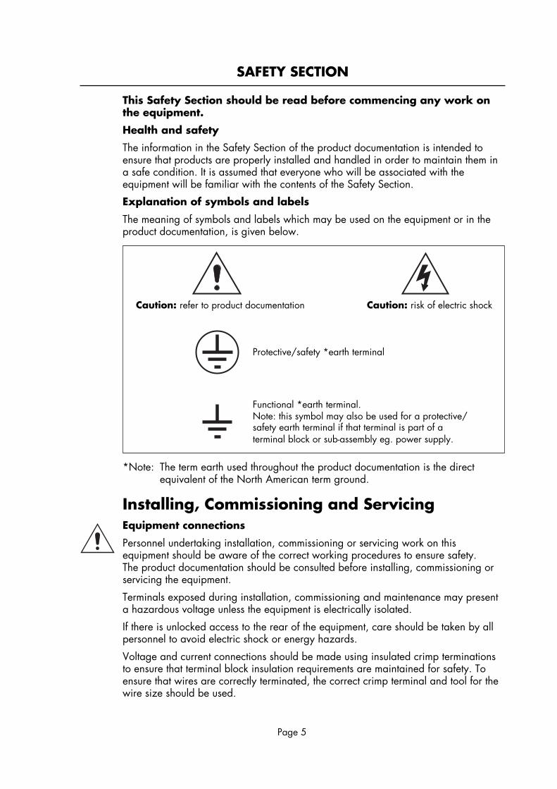
The meaning of symbols and labels which may be used on the equipment or in theproduct documentation, is given below.
Caution: refer to product documentation Caution: risk of electric shock
Protective/safety *earth terminal
Functional *earth terminal.Note: this symbol may also be used for a protective/safety earth terminal if that terminal is part of aterminal block or sub-assembly eg. power supply.
*Note: The term earth used throughout the product documentation is the directequivalent of the North American term ground.
Installing, Commissioning and ServicingEquipment connections
Personnel undertaking installation, commissioning or servicing work on thisequipment should be aware of the correct working procedures to ensure safety.The product documentation should be consulted before installing, commissioning orservicing the equipment.
Terminals exposed during installation, commissioning and maintenance may presenta hazardous voltage unless the equipment is electrically isolated.
If there is unlocked access to the rear of the equipment, care should be taken by allpersonnel to avoid electric shock or energy hazards.
Voltage and current connections should be made using insulated crimp terminationsto ensure that terminal block insulation requirements are maintained for safety. Toensure that wires are correctly terminated, the correct crimp terminal and tool for thewire size should be used.
Page 6
Before energising the equipment it must be earthed using the protective earthterminal, or the appropriate termination of the supply plug in the case of plugconnected equipment. Omitting or disconnecting the equipment earth may cause asafety hazard.
The recommended minimum earth wire size is 2.5 mm2, unless otherwise stated inthe technical data section of the product documentation.
Before energising the equipment, the following should be checked:
Voltage rating and polarity;
CT circuit rating and integrity of connections;
Protective fuse rating;
Integrity of earth connection (where applicable)
Equipment operating conditions
The equipment should be operated within the specified electrical and environmentallimits.
Current transformer circuits
Do not open the secondary circuit of a live CT since the high voltage producedmay be lethal to personnel and could damage insulation.
External resistors
Where external resistors are fitted to relays, these may present a risk of electric shockor burns, if touched.
Battery replacement
Where internal batteries are fitted they should be replaced with the recommendedtype and be installed with the correct polarity, to avoid possible damage to theequipment.
Insulation and dielectric strength testing
Insulation testing may leave capacitors charged up to a hazardous voltage. At theend of each part of the test, the voltage should be gradually reduced to zero, todischarge capacitors, before the test leads are disconnected.
Insertion of modules and pcb cards
These must not be inserted into or withdrawn from equipment whilst it is energised,since this may result in damage.
Fibre optic communication
Where fibre optic communication devices are fitted, these should not be vieweddirectly. Optical power meters should be used to determine the operation or signallevel of the device.
Page 7
Older ProductsElectrical adjustments
Equipments which require direct physical adjustments to their operating mechanism tochange current or voltage settings, should have the electrical power removed beforemaking the change, to avoid any risk of electric shock.
Mechanical adjustments
The electrical power to the relay contacts should be removed before checking anymechanical settings, to avoid any risk of electric shock.
Draw out case relays
Removal of the cover on equipment incorporating electromechanical operatingelements, may expose hazardous live parts such as relay contacts.
Insertion and withdrawal of extender cards
When using an extender card, this should not be inserted or withdrawn from theequipment whilst it is energised. This is to avoid possible shock or damage hazards.Hazardous live voltages may be accessible on the extender card.
Insertion and withdrawal of heavy current test plugs
When using a heavy current test plug, CT shorting links must be in place beforeinsertion or removal, to avoid potentially lethal voltages.
Decommissioning and Disposal
Decommissioning: The auxiliary supply circuit in the relay may include capacitorsacross the supply or to earth. To avoid electric shock or energyhazards, after completely isolating the supplies to the relay(both poles of any dc supply), the capacitors should be safelydischarged via the external terminals prior todecommissioning.
Disposal: It is recommended that incineration and disposal to watercourses is avoided. The product should be disposed of in asafe manner. Any products containing batteries should havethem removed before disposal, taking precautions to avoidshort circuits. Particular regulations within the country ofoperation, may apply to the disposal of lithium batteries.
Page 8
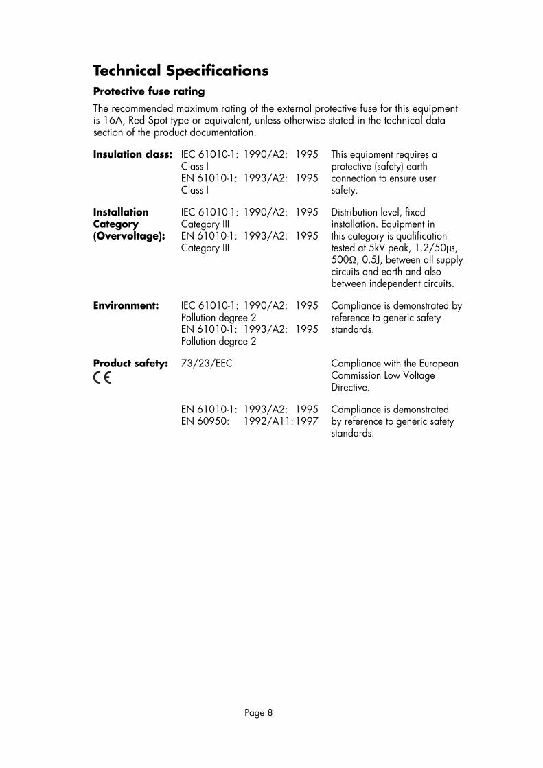
Technical SpecificationsProtective fuse rating
The recommended maximum rating of the external protective fuse for this equipmentis 16A, Red Spot type or equivalent, unless otherwise stated in the technical datasection of the product documentation.
Insulation class: IEC 61010-1: 1990/A2: 1995 This equipment requires aClass I protective (safety) earthEN 61010-1: 1993/A2: 1995 connection to ensure userClass I safety.
Installation IEC 61010-1: 1990/A2: 1995 Distribution level, fixedCategory Category III installation. Equipment in(Overvoltage): EN 61010-1: 1993/A2: 1995 this category is qualification
Category III tested at 5kV peak, 1.2/50µs,500Ω, 0.5J, between all supplycircuits and earth and alsobetween independent circuits.
Environment: IEC 61010-1: 1990/A2: 1995 Compliance is demonstrated byPollution degree 2 reference to generic safetyEN 61010-1: 1993/A2: 1995 standards.Pollution degree 2
Product safety: 73/23/EEC Compliance with the EuropeanCommission Low VoltageDirective.
EN 61010-1: 1993/A2: 1995 Compliance is demonstratedEN 60950: 1992/A11:1997 by reference to generic safety
standards.
Page 9
Section 1. INSTALLATION
1.1 General
Protective relays, although generally of robust construction, require careful treatmentprior to installation. By observing a few simple rules the possibility of prematurefailure is eliminated and a high degree of performance can be expected.
The relays are either despatched individually or as part of a panel/rack mountedassembly in cartons specifically designed to protect them from damage.
Relays should be examined immediately the are received to ensure that nodamage has been sustained in transit. If damage due to rough handling is evident,a claim should be made to the transport company concerned immediately, andALSTOM T&D Protection & Control promptly notified. Relays which are suppliedunmounted and not intended for immediate installation should be returned to theirprotective polythene bags.
1.2 Unpacking
Care must be taken when unpacking and installing the relays so that none of theparts are damaged or their setting altered, and must be handled by skilled persons atall times.
Relays should be examined for any wedges, clamps, or rubber bands necessary tosecure moving parts to prevent damage during transit and these should be removedafter installation and before commissioning.
Relays which have been removed form their cases should not be left in situationswhere they are exposed to dust or damp. This is particularly applies to installationswhich are being carried out at the same time as construction work.
1.3 Storage
If relays are not installed immediately upon receipt they should be stored in a placefree from dust and moisture in their original cartons and where de-humidifier bagshave been included in the packing they should be retained. The action of thede-humidifier crystals will be impaired if the bag has been exposed to ambientconditions and may be restored by gently heating the bag for about an hour, prior toplacing it in the carton.
Dust which collects on a carton may, on subsequent unpacking, find its way in to therelay; in damp conditions the carton and packing may become impregnated withmoisture and the de-humidifying agent will lose its efficiency.
The storage temperature range is –25°C to +70°C
1.4 Site
The installation should be clean, dry and reasonably free from dust and excessivevibration. The site should preferably be well illuminated to facilitate inspection.
An outline diagram is normally supplied showing panel cut-outs and hole centres.For individually mounted relays these dimensions will also be found in PublicationR6005.
Publication R7012 is a parts catalogue and assembly instructions. This document willbe useful when individual relays are to be assembled as a composite rack or panelmounted assembly.

Page 10
Publication R6001 is a leaflet on the modular integrated drawout system.
Publication R6014 is a list recommended suppliers for the pre-insulated connectors.
Section 2. COMMISSIONING
2.1 General
Before leaving the factory all relays are accurately adjusted, tested and carefullypacked. Hence there should be no need for any re-adjustment on commissioning.
Moving parts are held in position during transit by rubber bands and packing.These should be removed carefully.
2.2 Electrostatic discharges
The relay uses components which are sensitive to electrostatic discharges.When handling the module, care should be taken to avoid contact with componentsand electrical connections. When removed from the case for storage, the moduleshould be placed in an electrically conducting anti-static bag.
2.3 Wiring
Check that ratings of relay agree with the supplies to which it is to be connected.
Check all wiring connections to the relay, including the case earthing connectionabove the terminal block. It is especially important that dc supplies and magneticblowout contacts are wired with the correct polarity. The relay diagram numberappears inside the case.
2.4 Commissioning preliminaries
To gain access to the relay first loosen the captive cover screw and carefully removethe cover from the case.
The module can then be removed from the case by grasping the handles at the topand bottom of the front plate and pulling forwards.
Care must be taken to ensure that mechanical settings of the element are notdisturbed.
Carefully remove the rubber band securing the flag mechanism
Check that the bottom end of the contact operating card has not been dislodged fromthe slot in the armature extension and that the ends of the push rods are located inthe holes in the contact springs.
Carefully actuate the armature of each unit in turn with small screwdriver/probe.Note immediately after the point where any make contacts just close there is a furthersmall movement of the armature. This ensures that contact follow through and wipingaction is present. Repeat similarly with break contacts on armature release.
On units fitted with hand reset flag indicators, check that the flag is free to fall before,or just as, any make contacts close.
Replace the module in the case and refit the cover. Make sure that the resetmechanism in the cover is correctly located with respect to the relay element, and thatthe flag (or mechanism) can be reset.
Page 11
2.5 Insulation
The relay and its associated wiring, may be insulation tested between:
a) all electrically isolated circuits
b) all circuits and earth
An electronic or brushless insulation tester should be used, having a dc voltage notexceeding 1000V. Accessible terminals of the same circuit should first be strappedtogether. Deliberate circuit earthing links, removed for tests, susequently must bereplaced.
Check operation by energising the relay with 80% of the rated supply voltage.The appropriate terminals should be identified from the internal wiring diagramnormally supplied.
Disconnect external wiring from these terminals to allow application of the testsupply.
The relay should switch cleanly with one movement.
The rated voltages are marked on either the lower handle strip or front plate.
Restore any external wiring connections that may have been disturbed duringthe above tests.
Section 3. MAINTENANCE
Periodic maintenance is not necessary. However, periodic inspection and test isrecommended. This should be carried out every 12 months or more often if the relayis operated frequently or is mounted in poor environmental conditions.
Repeat check 2.3 with emphasis on contact wear and condition. Mechanical settingsmay be checked against those shown in Section 4.
Section 4. MECHANICAL SETTINGS
4.1 General
Armature gap measurements should be made with the top of the feeler gauge levelwith the centre line of the core.
Contact pressures are measured with gramme gauge at the contact tips.
In general contact gaps and follow through are defined by quoting an armature gapat which the tips should be just closed or just open.
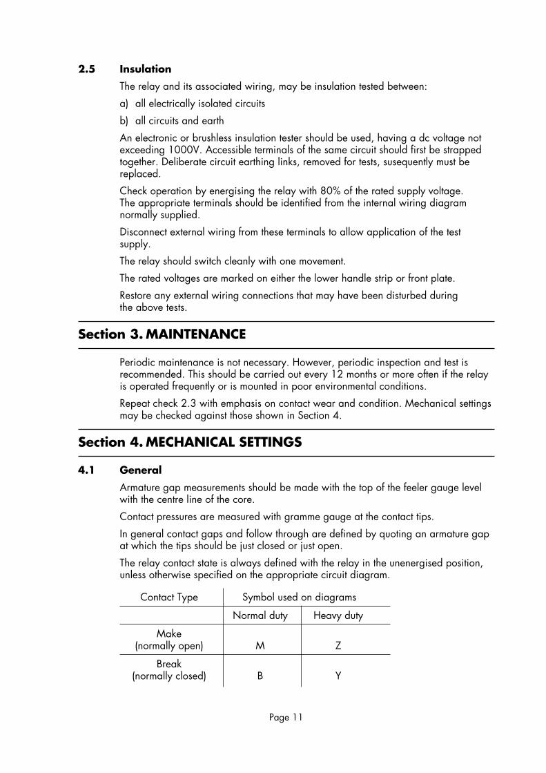
The relay contact state is always defined with the relay in the unenergised position,unless otherwise specified on the appropriate circuit diagram.
Contact Type Symbol used on diagrams
Normal duty Heavy duty
Make(normally open) M Z
Break(normally closed) B Y
Page 12
With the armature closed the clearance between the back of the armature and theback stop should be 0.003"/0".008".
Nominal armature gap open 0.050"/0.060".
4.2 Contact setting
Normal/heavy duty make and break contacts.
With the armature closed onto a 0.011" feeler gauge the make contact should beclosed, but should be open using a 0.013" feeler gauge.
With the armature closed onto a 0.027" feeler gauge the break contact should beopen, but should be closed using a 0.29" feeler.
Force to just open the break contacts 20/25 grams.
Force to just close the make contacts 18/23 grams.
4.3 Contact flash guard
On relays fitted with a contact flash guard it will be necessary to remove the guardbefore the contact spring pressures can be measured, this is best performed by thefollowing procedure as described below:
a) Prise back the four contact guard restraining clips.
b) Depress the armature of the relay using a small screwdriver or a probe.
c) Slide the flash guard out forward, taking care not to damage the contacts.
Replacing the contact guard is performed as follows:
a) Reset the contact guard retaining clips to their normal holding position.
b) Depress the armature of the relay using a small screwdriver or probe.
c) Replace the flash guard taking care not to damage the contact clips so as toremove any free movement in the contact guard.
4.4 Mechanical flag setting
With the armature closed onto a 0.013" feeler gauge the flag should be free to fall,but should not fall using a 0.018" feeler gauge.
Adjustment is made to the catch spring on the flag.
Section 5. PROBLEM ANALYSIS
5.1 Failure to operate
Check diagram for correct input connections.
Check internal wiring for loose or damaged joints.
Flag spring may be distorted holding the armature open.
Check continuity - result open circuit
Coil open circuit.
Series resistor open circuit.
Check continuity - result short circuit.
Capacitor damaged - relay takes excessive current.
Page 13
5.2 Excessive current taken by relay
Capacitor damage.
Incorrect voltage applied.
External resistors not connected.
Internal resistors short circuit.
5.3 Output cards not changing state.
Operating card not in position.
Check output terminals with reference to diagram.
Internal wiring damage.
Contamination of contacts.
Contacts contaminated- these should be cleaned with a burnishing tool, supplied inrelay tool kits
On on account should knives, files or abrasive materials be used.
Check mechanical settings as per Section 4.
Section 6. SPARES
When ordering spares, quote the full relay model number and any componentreference numbers, or briefly describe the parts.
Repairs
Should the need arise for the equipment to be returned to ALSTHOM T&D Protection& Control Ltd for repair, then the form at the back of this manual should becompleted and sent with the equipment together with a copy of any commissioningtest results.

Page 14

Page 15
Section 7. COMMISSIONING TEST RECORD
MVAW INTERPOSING RELAY
Site Circuit
Model No. Serial No.
Rating Diagrams
1. Check operation
Pick-up voltage
Pick-up current
Drop-off voltage
Drop-off current
2. Check contact operation
Check flag operation
Remarks:
______________________________________ _______________________________________Commissioning Engineer Customer Witness
______________________________________ _______________________________________Date Date

Page 16

Page 17
continued overleaf
REPAIR FORM
Please complete this form and return it to ALSTHOM T&D Protection & Control Ltd with theequipment to be repaired. This form may also be used in the case of application queries.
ALSTHOM T&D Protection & Control LtdSt. Leonards WorksStaffordST17 4LXEngland
For: After Sales Service Department
Customer Ref: ___________________________ Model No: __________________
Contract Ref: ___________________________ Serial No: __________________
Date: ___________________________
1. What parameters were in use at the time the fault occurred?
AC volts _____________ Main VT/Test set
DC volts _____________ Battery/Power supply
AC current _____________ Main CT/Test set
Frequency _____________
2. Which type of test was being used? ____________________________________________
3. Were all the external components fitted where required? Yes/No(Delete as appropriate.)
4. List the relay settings being used
____________________________________________________________________________
____________________________________________________________________________
____________________________________________________________________________
5. What did you expect to happen?
____________________________________________________________________________
____________________________________________________________________________
____________________________________________________________________________
____________________________________________________________________________

Page 18
6. What did happen?
____________________________________________________________________________
____________________________________________________________________________
____________________________________________________________________________
____________________________________________________________________________
7. When did the fault occur?
Instant Yes/No Intermittent Yes/No
Time delayed Yes/No (Delete as appropriate).
By how long? ___________
8. What indications if any did the relay show?
____________________________________________________________________________
____________________________________________________________________________
____________________________________________________________________________
9. Was there any visual damage?
____________________________________________________________________________
____________________________________________________________________________
____________________________________________________________________________
10. Any other remarks which may be useful:
____________________________________________________________________________
____________________________________________________________________________
____________________________________________________________________________
______________________________________ _______________________________________Signature Title
______________________________________ _______________________________________Name (in capitals) Company name

Page 19

A L S T O M T & D P r o t e c t i o n & C o n t r o l L t d St Leonards Works, Stafford, ST17 4LX EnglandTel: 44 (0) 1785 223251 Fax: 44 (0) 1785 212232 Email: [email protected] Internet: www.alstom.com
©1999 ALSTOM T&D Protection & Control Ltd
Our policy is one of continuous product development and the right is reserved to supply equipment which may vary from that described.
Publication R8005C Printed in England.
Related Documents


