Model:R718PE Wireless Top Mounted Ultrasonic Liquid Level Sensor Wireless Top Mounted Ultrasonic Liquid Level Sensor R718PE User Manual Copyright©Netvox Technology Co., Ltd. This document contains proprietary technical information which is the property of NETVOX Technology. It shall be maintained in strict confidence and shall not be disclosed to other parties, in whole or in part, without written permission of NETVOX Technology. The specifications are subject to change without prior notice.

Welcome message from author
This document is posted to help you gain knowledge. Please leave a comment to let me know what you think about it! Share it to your friends and learn new things together.
Transcript

Model:R718PE
Wireless Top Mounted Ultrasonic Liquid Level Sensor
Wireless Top Mounted Ultrasonic Liquid Level Sensor
R718PE
User Manual
Copyright©Netvox Technology Co., Ltd.
This document contains proprietary technical information which is the property of NETVOX Technology. It shall be maintained
in strict confidence and shall not be disclosed to other parties, in whole or in part, without written permission of NETVOX
Technology. The specifications are subject to change without prior notice.

1
Table of Content 1. Introduction ....................................................................................................................................................................................... 2
2. Appearance ........................................................................................................................................................................................ 2
3. Main Features ................................................................................................................................................................................... 3
4. Set up Instruction .............................................................................................................................................................................. 4
5. Data Report ....................................................................................................................................................................................... 5
6. Application scenario ....................................................................................................................................................................... 10
7. Installation ...................................................................................................................................................................................... 11
8. Information about Battery Passivation ........................................................................................................................................... 13
8.1 To determine whether a battery requires activation................................................................................................................ 13
8.2 How to activate the battery ..................................................................................................................................................... 13
9. Important Maintenance Instruction ................................................................................................................................................ 14

2
1. Introduction R718PE is a Wireless Top Mounted Ultrasonic Liquid Level Sensor device for Netvox ClassA type devices based on the
LoRaWAN open protocol and is compatible with the LoRaWAN protocol.
R718PE uses ultrasound to detect the distance between the device and the detected object. The medium the device detects is the
air, so the detected object can be any liquid or solid that has a flat and horizontal surface, water level.
LoRa Wireless Technology:
LoRa is a wireless communication technology dedicated to long distance and low power consumption. Compared with other
communication methods, LoRa spread spectrum modulation method greatly increases to expand the communication distance.
Widely used in long-distance, low-data wireless communications. For example, automatic meter reading, building automation
equipment, wireless security systems, industrial monitoring. Main features include small size, low power consumption,
transmission distance, anti-interference ability and so on.
LoRaWAN:
LoRaWAN uses LoRa technology to define end-to-end standard specifications to ensure interoperability between devices and
gateways from different manufacturers.
2. Appearance
Ultrasonic Ranging Sensor
Indicator
Function Key

3
3. Main Features
Apply SX1276 wireless communication module
2 sections ER14505 3.6V Lithium AA battery
Liquid level detection
Protection Level: IP65 / IP67 (optional), Ultrasonic Ranging Sensor: IP67
Compatible with LoRaWANTM Class A
Frequency hopping spread spectrum technology
Configuration parameters can be configured through third-party software platforms, data can be read and alarms can be set via
SMS text and email (optional)
Available third-party platform: Actility / ThingPark, TTN, MyDevices/Cayenne
Low power consumption and long battery life
Note:
Battery life is determined by the sensor reporting frequency and other variables, please refer to
http://www.netvox.com.tw/electric/electric_calc.html. On this website, users can find battery life time for varied models at
different configurations.

4
4. Set up Instruction
On/Off
Power on Insert batteries. (users may need a flat blade screwdriver to open)
Turn on Press and hold the function key for 3 seconds till the green indicator flashes once.
Turn off (Restore to factory
setting) Press and hold the function key for 5 seconds till green indicator flashes for 20 times.
Power off Remove Batteries.
Note:
1. Remove and insert the battery; the device is at off state by default.
2. On/off interval is suggested to be about 10 seconds to avoid the interference of capacitor
inductance and
other energy storage components.
3. At 1st -5th second after power on, the device will be in engineering test mode.
Network Joining
Never joined the network
Turn on the device to search the network to join.
The green indicator stays on for 5 seconds: success
The green indicator remains off: fail
Had joined the network
(not at factory setting)
Turn on the device to search the previous network to join.
The green indicator stays on for 5 seconds: success
The green indicator remains off: fail
Function Key
Press and hold for 5 seconds
Restore to factory setting / Turn off
The green indicator flashes for 20 times: success
The green indicator remains off: fail
Press once The device is in the network: green indicator flashes once and sends a report
The device is not in the network: green indicator remains off
Sleeping Mode
The device is on and in the
network
Sleeping period: Min Interval.
When the reportchange exceeds setting value or the state changes: send a data report according
to Min Interval.
Low Voltage Warning
Low Voltage 3.2V

5
5. Data Report
Example of ConfigureCmd
FPort:0x07
Bytes 1 1 Var(Fix =9 Bytes)
CmdID DeviceType NetvoxPayLoadData
CmdID– 1 bytes
DeviceType– 1 byte – Device Type of Device
NetvoxPayLoadData– var bytes (Max=9bytes)
The device will immediately send a version packet report along with an uplink packet including status, distance, filllevel and
battery voltage.
Status:
When the device is used for water level detection/waste bin detection, the status always reports "0".
When the device is used for parking detection, the distance between the device and the car reaches the
OnDistanceThreshold, it reports status ON.
Distance:
The distance between the device and the liquid / solid
Filllevel:
The percentage of the level in the container.
When the device is used for parking detection, the status always reports "0".
The device sends data in the default configuration before any configuration is done.
Default Setting
Maximum time: Max Interval = 15 min
Minimum time: Min Interval = 15 min
BatteryVoltageChange - 0x01 (0.1V)
DistanceChange - 0x012C(300mm)
Note:
1. The device report interval will be programmed based on the default firmware which may vary.
2. The interval between two reports must be the MinTime
3. The data parsing reported by the device is referenced by the Netvox LoRaWAN Application Command document and
http://www.netvox.com.cn:8888/page/index
6
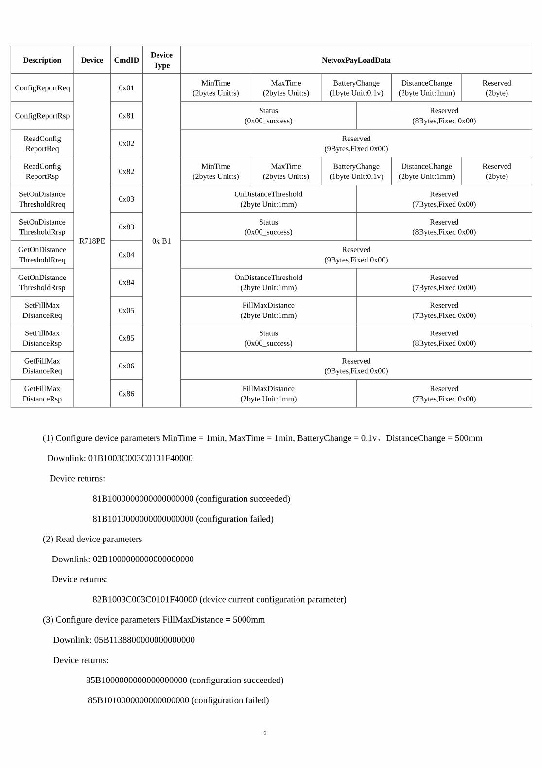
(1) Configure device parameters MinTime = 1min, MaxTime = 1min, BatteryChange = 0.1v、DistanceChange = 500mm
Downlink: 01B1003C003C0101F40000
Device returns:
81B1000000000000000000 (configuration succeeded)
81B1010000000000000000 (configuration failed)
(2) Read device parameters
Downlink: 02B1000000000000000000
Device returns:
82B1003C003C0101F40000 (device current configuration parameter)
(3) Configure device parameters FillMaxDistance = 5000mm
Downlink: 05B1138800000000000000
Device returns:
85B1000000000000000000 (configuration succeeded)
85B1010000000000000000 (configuration failed)
Description Device CmdID Device Type NetvoxPayLoadData
ConfigReportReq
R718PE
0x01
0x B1
MinTime (2bytes Unit:s)
MaxTime (2bytes Unit:s)
BatteryChange (1byte Unit:0.1v)
DistanceChange (2byte Unit:1mm)
Reserved (2byte)
ConfigReportRsp 0x81 Status (0x00_success)
Reserved (8Bytes,Fixed 0x00)
ReadConfig ReportReq 0x02 Reserved
(9Bytes,Fixed 0x00)
ReadConfig ReportRsp 0x82 MinTime
(2bytes Unit:s) MaxTime
(2bytes Unit:s) BatteryChange
(1byte Unit:0.1v) DistanceChange
(2byte Unit:1mm) Reserved (2byte)
SetOnDistance ThresholdRreq 0x03 OnDistanceThreshold
(2byte Unit:1mm) Reserved
(7Bytes,Fixed 0x00)
SetOnDistance ThresholdRrsp 0x83 Status
(0x00_success) Reserved
(8Bytes,Fixed 0x00)
GetOnDistance ThresholdRreq 0x04 Reserved
(9Bytes,Fixed 0x00)
GetOnDistance ThresholdRrsp 0x84 OnDistanceThreshold
(2byte Unit:1mm) Reserved
(7Bytes,Fixed 0x00)
SetFillMax DistanceReq 0x05 FillMaxDistance
(2byte Unit:1mm) Reserved
(7Bytes,Fixed 0x00)
SetFillMax DistanceRsp 0x85 Status
(0x00_success) Reserved
(8Bytes,Fixed 0x00)
GetFillMax DistanceReq 0x06 Reserved
(9Bytes,Fixed 0x00)
GetFillMax DistanceRsp 0x86 FillMaxDistance
(2byte Unit:1mm) Reserved
(7Bytes,Fixed 0x00)

7
(4) Read device parameters FillMaxDistance
Downlink: 06B1000000000000000000
Device returns:
86B1138800000000000000 (device current configuration parameter)
Level Sensor Calibrate configuration example:
FPort:0x0E
Description CmdID SensorType PayLoad(Fix =9 Bytes)
SetGlobal CalibrateReq 0x01
0x36
Channel(1Byte) 0_Channel1,
1_Channel2,etc
Multiplier (2bytes,Unsigned)
Divisor (2bytes,Unsigned)
DeltValue (2bytes,Signed)
Reserved (2Bytes,Fixed 0x00)
SetGlobal CalibrateRsp 0x81
Channel(1Byte) 0_Channel1,
1_Channel2,etc
Status (1Byte,0x00_success)
Reserved (7Bytes,Fixed 0x00)
GetGlobal CalibrateReq 0x02 Channel
(1Byte,0_Channel1,1_Channel2,etc) Reserved
(8Bytes,Fixed 0x00)
GetGlobal CalibrateRsp 0x82
Channel(1Byte) 0_Channel1,
1_Channel2,etc
Multiplier (2bytes,Unsigned)
Divisor (2bytes,Unsigned)
DeltValue (2bytes,Signed)
Reserved (2Bytes,Fixed 0x00)
ClearGlobal CalibrateReq 0x03 Reserved
(10Bytes,Fixed 0x00)
ClearGlobal CalibrateRsp 0x83 Status
(1Byte,0x00_success) Reserved
(9Bytes,Fixed 0x00)
(1) Set the calibration (GlobalCalibrate configuration):
If the distance between the device and the water R718PE detects is 490mm and the actual distance is 500mm, it means the
calibration we want to make is +10mm.
Channel 1= 00, Multiplier = 000A, Divisor = 0000, DeltValue=0001
Downlink:013600000A000000010000
Response:
8136000000000000000000(Configuration success)
8136010000000000000000(Configuration failure)
(2) Check whether the setting in (1) calibration
Downlink:0236000000000000000000
Response:
823600000A000000010000(Current configuration)
(3) Clear the setting
Downlink:0300000000000000000000
Response:
8300000000000000000000(Configuration success)
8
8301000000000000000000(Configuration failure)
Note:
1. When Multiplier is not 1, Calibration value = DeltValue*Multiplier.
2. When Divisor is not 1, Calibration value = DeltValue/Divisor.
3. The choices of the Channel would be 00-03 Channel
4. With different sensor type, it is forbidden to use that same Channel number.
5. This universal calibration supports calibration of positive and negative numbers.
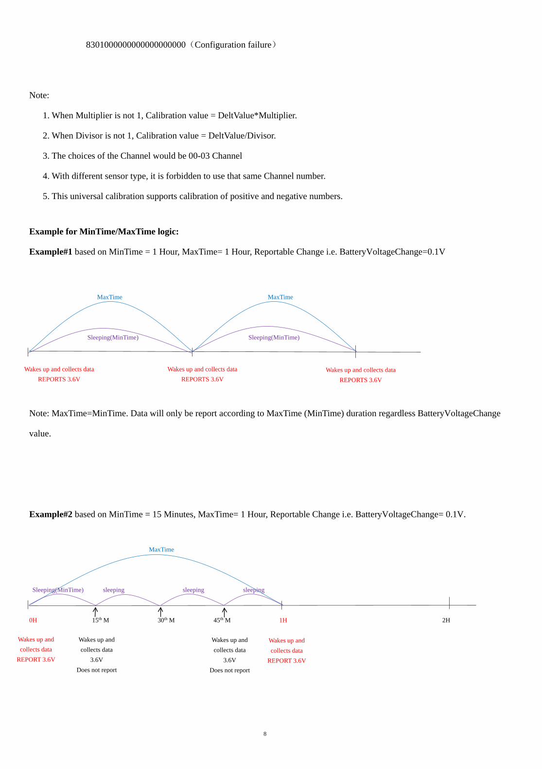
Example for MinTime/MaxTime logic:
Example#1 based on MinTime = 1 Hour, MaxTime= 1 Hour, Reportable Change i.e. BatteryVoltageChange=0.1V MaxTime MaxTime Sleeping(MinTime) Sleeping(MinTime)
Note: MaxTime=MinTime. Data will only be report according to MaxTime (MinTime) duration regardless BatteryVoltageChange
value.
Example#2 based on MinTime = 15 Minutes, MaxTime= 1 Hour, Reportable Change i.e. BatteryVoltageChange= 0.1V. MaxTime Sleeping(MinTime) sleeping sleeping sleeping 0H 15th M 30th M 45th M 1H 2H
Wakes up and collects data REPORTS 3.6V
Wakes up and collects data REPORTS 3.6V
Wakes up and collects data
3.6V Does not report
Wakes up and collects data
REPORT 3.6V
Wakes up and collects data
REPORT 3.6V
Wakes up and collects data
3.6V Does not report
Wakes up and collects data REPORTS 3.6V

9
Example#3 based on MinTime = 15 Minutes, MaxTime= 1 Hour, Reportable Change i.e. BatteryVoltageChange= 0.1V. MaxTime sleeping sleeping ... 0H 15th M 30th M 45th M 1H 1H 10th M 1H 25th M 1H 40th M 1H 55th M 2H 10th M
Notes :
1) The device only wakes up and performs data sampling according to MinTime Interval. When it is sleeping, it does not
collect data.
2) The data collected is compared with the last data reported. If the data variation is greater than the ReportableChange value,
the device reports according to MinTime interval. If the data variation is not greater than the last data reported, the device
reports according to MaxTime interval.
3) We do not recommend to set the MinTime Interval value too low. If the MinTime Interval is too low, the device wakes up
frequently and the battery will be drained soon.
4) Whenever the device sends a report, no matter resulting from data variation, button pushed or MaxTime interval, another
cycle of MinTime/MaxTime calculation is started.
Wakes up and collects data
REPORTS 3.6V
Wakes up and collects data
3.5V Does not report
Wakes up and collects data
3.5V Does not report
Wakes up and collects data
3.5V Does not report
Wakes up and collects data
3.5V Does not report
Wakes up and collects data REPORTS
3.5V
Wakes up and collects data
3.6V Does not report
Users push the button, REPORTS 3.5V. Recalculate MaxTime.
Wakes up and collects data
3.5V |3.5-3.6|=0.1 REPORTS 3.5V
Wakes up and collects data 3.5V
Does not report

10
6. Application scenario
In the use case of detecting the water level in water tanks, the device should be installed on the top of the water tank.
After the device is installed and powered, turn on the device and it will detect the distance between the device and the water as
well as the percentage
of the water level in the water tank.
H means the height of the water tank (this value can be set with the payload command; the “fillmaxdistance” in payload
means H)
D means the distance between the device and the water (this value is “distance” in uplinks)
L means the water level (this value can be calculated by the “distance” in uplink and “fillmaxdistance” in payload)
Calculation: L = fillmaxdistacnce - distance
FillLevel means the percentage of the water level in the water tank.
FillLevel = ((H - D) / H) * 100%
Note:
H can be set in accordance with the height of different water tanks that are used in the use case
The detecting range of the device is 250mm~8000mm
Illustration

11
7. Installation
Kindly note the illustration is only for reference.
1. The device can be installed in the middle or anywhere of the top of the container that is flat enough to ensure the ultrasonic
detection direction will be vertical to the detected object, so the accuracy can be maintained.
2. When the use case is water tank, the diameter of the water tank is recommended to be larger than 60cm.
3. Customers can refer to the below formula to see if the container is suitable:
tan7.5°=A / B
A is the radius of the container (water tank),
B is the height of the container (water tank);
tan7.5° A B
0.1316
3.9 30
6.6 50
13.2 100
19.7 150
26.3 200
32.9 250
39.5 300
46.1 350
52.6 400
59.2 450
65.8 500
72.4 550
79.0 600
85.5 650
92.1 700
98.7 750
105.3 800
Reference Form Unit: cm A
B

12
4. If the top of the water tank can be opened, it is recommended to make a hole of diameter 32mm on the top of the water tank.
5. If the top of the water tank cannot be opened, the hole made on the top of the water tank is recommended to be 45mm diameter.
It is recommended to add a gasket (size: 32.4*57.4*3mm) between the hole and the sensor.

13
6. Movement of the detected water/liquid and foams would affect the accuracy.
7. Keep the ultrasonic detecting range from obstacles.
8. Keep the device from electromagnetic disturbances.
8. Information about Battery Passivation
Many of Netvox devices are powered by 3.6V ER14505 Li-SOCl2 (lithium-thionyl chloride) batteries that offer many
advantages including low self-discharge rate and high energy density.
However, primary lithium batteries like Li-SOCl2 batteries will form a passivation layer as a reaction between the lithium
anode and thionyl chloride if they are in storage for a long time or if the storage temperature is too high. This lithium chloride
layer prevents rapid self-discharge caused by continuous reaction between lithium and thionyl chloride, but battery passivation
may also lead to voltage delay when the batteries are put into operation, and our devices may not work correctly in this situation.
As a result, please make sure to source batteries from reliable vendors, and the batteries should be produced within the last
three months.
If encountering the situation of battery passivation, users can activate the battery to eliminate the battery hysteresis.
8.1 To determine whether a battery requires activation
Connect a new ER14505 battery to a 68ohm resistor in parallel, and check the voltage of the circuit.
If the voltage is below 3.3V, it means the battery requires activation.
8.2 How to activate the battery
a. Connect a battery to a 68ohm resistor in parallel
b. Keep the connection for 6~8 minutes
c. The voltage of the circuit should be ≧3.3V

14
9. Important Maintenance Instruction
Kindly pay attention to the following in order to achieve the best maintenance of the product:
• Keep the device dry. Rain, moisture, or any liquid, might contain minerals and thus corrode electronic circuits. If the device gets
wet, please dry it completely.
• Do not use or store the device in dusty or dirty environment. It might damage its detachable parts and electronic components.
• Do not store the device under excessive heat condition. High temperature can shorten the life of electronic devices, destroy
batteries, and deform or melt some plastic parts.
• Do not store the device in places that are too cold. Otherwise, when the temperature rises to normal temperature, moisture will
form inside, which will destroy the board.
• Do not throw, knock or shake the device. Rough handling of equipment can destroy internal circuit boards and delicate
structures.
• Do not clean the device with strong chemicals, detergents or strong detergents.
• Do not apply the device with paint. Smudges might block in the device and affect the operation.
• Do not throw the battery into the fire, or the battery will explode. Damaged batteries may also explode.
All of the above applies to your device, battery and accessories. If any device is not working properly, please take it to the nearest
authorized service facility for repair.
Related Documents