GEC ALSTHOM T&D PROTECTION & CONTROL LIMITED, St Leonards Works, Stafford ST17 4LX, England Tel: 01785 223251 Telex: 36240 Fax: 01785 212232 Courier Protocol for K-Bus, IEC870 and general implementations R6511 B

Welcome message from author
This document is posted to help you gain knowledge. Please leave a comment to let me know what you think about it! Share it to your friends and learn new things together.
Transcript
GEC ALSTHOM T&D PROTECTION & CONTROL LIMITED, St Leonards Works, Stafford ST17 4LX, EnglandTel: 01785 223251 Telex: 36240 Fax: 01785 212232
Courier Protocol
for K-Bus, IEC870 andgeneral implementations
R6511 B
2 Preface
3-Feb-98 R6511 B R6511b.doc

Preface 3
R6511b.doc R6511 B 3-Feb-98
Preface
This document details the IEC870 communication standard used on GEC ALSTHOM T&DProtection & Control relays in sufficient detail to enable third parties to interface these relays toother systems and to develop other slave devices (relays) which utilise this communicationsystem. It describes how messages are formed and transmitted from one device to another. Itdoes not describe what the messages mean as this is dependent on the application to whichIEC870 is put and the particular format of the data that is transmitted.
This guide should be used with the appropriate user guide for the particular application thatthe IEC870 system will be used with.
The information and illustrations found in this book are not binding. GEC ALSTHOM T&DProtection & Control Ltd. reserve the right to modify products in line with a policy ofcontinuous product improvement. Information in this document is subject to change withoutnotice.
4 Table of Contents
3-Feb-98 R6511 B R6511b.doc
Table of Contents 5
R6511b.doc R6511 B 3-Feb-98
Table of Contents Page
Preface ..................................................................................3
Chapter 1: Introduction ..........................................................7
Chapter 2: Protocol Rules .......................................................92.1. COURIER PROTOCOL RULES SUMMARY ..............................................................................92.2. COURIER MESSAGE STRUCTURE........................................................................................10
2.2.1. REPLY CONTROL FIELD ...................................................................................................102.3. COURIER PROTOCOL OVERVIEW ......................................................................................12(MASTER CONTROL UNIT) ........................................................................................................12
2.3.1. LAYER 6: ASYNCHRONOUS EVENT LAYER. ...........................................................................152.3.2. LAYER 5: TIME SYNCHRONISATION LAYER. ..........................................................................162.3.3. LAYER 4: BUSY RESPONSE LAYER. ......................................................................................172.3.4. LAYER 3: IEC CONTROL LAYER. .......................................................................................182.3.5. LAYER 2: TRANSLATION LAYER. .........................................................................................202.3.6. LAYER 1: RETRANSMISSION LAYER......................................................................................21
2.4. COURIER PROTOCOL OVERVIEW ......................................................................................25(SLAVE DEVICE) ........................................................................................................................25
2.4.1. LAYER 1: TRANSLATION LAYER. .........................................................................................282.4.2. LAYER 2: IEC CONTROL LAYER. .......................................................................................292.4.3. LAYER 3: GLOBAL MESSAGE LAYER....................................................................................312.4.4. LAYER 4: TIME SYNCHRONISATION....................................................................................312.4.5. LAYER 5: LOW LEVEL ......................................................................................................32
2.5. IEC CONTROL FIELD .........................................................................................................36
Chapter 3: Automatic Data Retrieval .....................................393.1. EVENT RECORDS...............................................................................................................393.2. PLANT STATUS WORD .......................................................................................................403.3. CONTROL STATUS WORD.................................................................................................413.4. TRIP INDICATIONS ............................................................................................................413.5. ALARM INDICATIONS........................................................................................................41
Chapter 4: Time Synchronisation ..........................................43
6 Chapter 1: Introduction
3-Feb-98 R6511 B R6511b.doc
Chapter 1: Introduction 7
R6511b.doc R6511 B 3-Feb-98
Chapter 1: Introduction
The Courier Protocol binds the Courier language to a particular communication network. Itdefines a set of low-level rules and implementation details to enable many of the automaticfeatures of a Courier based system to be performed on different systems. Some of the lowerlayers of the protocol may be implemented by the communication network itself and thereforethe protocol layers may be network specific.
Courier transactions, Courier commands, message structures and so on are described fully inthe Courier User Guide, to which reference should be made.
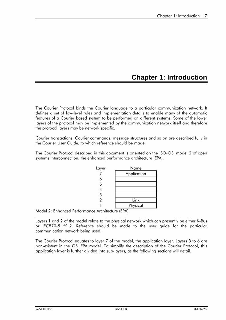
The Courier Protocol described in this document is oriented on the ISO-OSI model 2 of opensystems interconnection, the enhanced performance architecture (EPA).
Model 2: Enhanced Performance Architecture (EPA)
Layers 1 and 2 of the model relate to the physical network which can presently be either K-Busor IEC870-5 ft1.2. Reference should be made to the user guide for the particularcommunication network being used.
The Courier Protocol equates to layer 7 of the model, the application layer. Layers 3 to 6 arenon-existent in the OSI EPA model. To simplify the description of the Courier Protocol, thisapplication layer is further divided into sub-layers, as the following sections will detail.
Layer Name7 Application65432 Link1 Physical

8 Chapter 1: Introduction
3-Feb-98 R6511 B R6511b.doc

Chapter 2: Protocol Rules 9
R6511b.doc R6511 B 3-Feb-98
Chapter 2: Protocol Rules
Courier uses a set of protocol rules to define the low level operation of Courier and howsingle request and reply messages may be sent over the communication network.
2.1. COURIER PROTOCOL RULES SUMMARY
• There may be multiple slave devices on a communication bus, but only one master can beactive at any time.
• Courier uses a 'Master-Slave' or 'Polled' protocol.• Slave devices cannot initiate a communication transaction.• No slave devices will reply to a global message broadcast from a master control unit.• A slave device must receive a global message twice in succession with no other intervening
valid message, before it will accept and execute the command.• A slave device will only send a communication message in response to a request from a
master control unit to a unique address.• A slave device must reply to a request within a response time of 5ms.• If a slave device cannot generate the correct reply within the response time, it will send an
empty BUSY message as a reply, thus allowing the master control unit to use the busagain.
• Slave responses (except blocked transactions) are always of the same type and length for agiven request.
• Any communication messages received in error will be completely ignored, as if there wasno message at all.
• If a master control unit does not receive a reply to its request within the time-out period, itwill retry several times before it determines that the slave device is not communicating.

10 Chapter 2: Protocol Rules
3-Feb-98 R6511 B R6511b.doc
2.2. COURIER MESSAGE STRUCTURE
The full Courier message structure is described in detail in the Courier User Guide. Anoverview is given here to give some understanding of the format of the examples in thefollowing sections and in particular to introduce the concept of the Reply Control Field which ishandled by the Courier Protocol, although its components are described in the Courier UserGuide.
A Courier request message consists of 3 fields: an address field, a length field and a user datafield. As far as the application is concerned a response message also consists of the samethree fields, but in reality an additional reply control field is inserted by the Courier Protocol inthe slave device and handled by the Courier Protocol in the master control unit.
Courier Request Message FormatAddress Length User DataField Field Field
Courier Reply Message FormatAddress Length Reply Control User DataField Field Field Field
2.2.1. REPLY CONTROL FIELD
The reply control field is only present in messages transmitted to the master control unit as itindicates various items of status information about the slave device. It is not present in thereply to a Reset Remote Link Command. It consists of one or more Courier data packetsterminated with a data packet of type 5Dh, indicating the Courier status byte.
DTL time Tag 4 byte millisecond DTL IEC870 Real-time DTL Status Status(38h) + (04h) timer count value time & date time-tag 5Dh
↑ ↑↑
This data packet is only required if slavedevice has no real time clock
This data packet optionallyinserted by a protocolconverter.
Additional data packetsmay be inserted here infuture.
The first packet is an optional time-tag which is used for the time-alignment of events withindifferent relays. Slave devices which include their own real time clock will omit this data packetsince time alignment will not be necessary. Other slave devices will include a data packet witha four byte millisecond timer count value and a DTL of 38h.
Time alignment is only possible if the communication propagation delay time between a slavedevice and a master control unit is short and consistent. In instances where a protocolconverter is used to transfer data over modems or other transmission mediums, timealignment is partially performed at the protocol converter itself. This is done by the protocolconverter inserting a real-time time-tag in IEC870 time & date data packet format immediatelyafter the millisecond timer count data packet. Time synchronisation is discussed chapter 4.

Chapter 2: Protocol Rules 11
R6511b.doc R6511 B 3-Feb-98
The last packet is always present and contains the status information of the slave device. TheDTL has a value of 5Dh and is followed by a single status byte. This status packet will ALWAYSbe the last packet in the reply control field. Should the reply control field be extended in thefuture by adding additional packets, this status packet can be used to determine the start ofthe user data field. This status byte is used to perform automatic data retrieval from the slavedevice which is discussed in a later chapter, and to inform the master control unit of variouschanges of state that have occurred.
The reply control field is transparent to the application layer. It allows additional informationabout the slave device to be provided automatically and made directly available to theapplication, rather than including it in the response to a request message.
The Courier protocol is described in the next two sections, both for the master control unit andthe slave device. Each protocol layer is described as a single process, yet having two datapaths: one for requests and one for responses, each having separate inputs and outputs. Eachlayer will process the input request to produce an output request and the input response toproduce an output response. In some layers this process may be a straight copy, in others itwill be a trivial conversion. In the master control unit an input response from a slave devicemight generate further output requests and corresponding input responses before the outputresponse is returned to the next higher layer.
Examples of the expected fields to be found in these inputs and outputs are given for eachlayer.
12 Chapter 2: Protocol Rules Master Device
3-Feb-98 R6511 B R6511b.doc
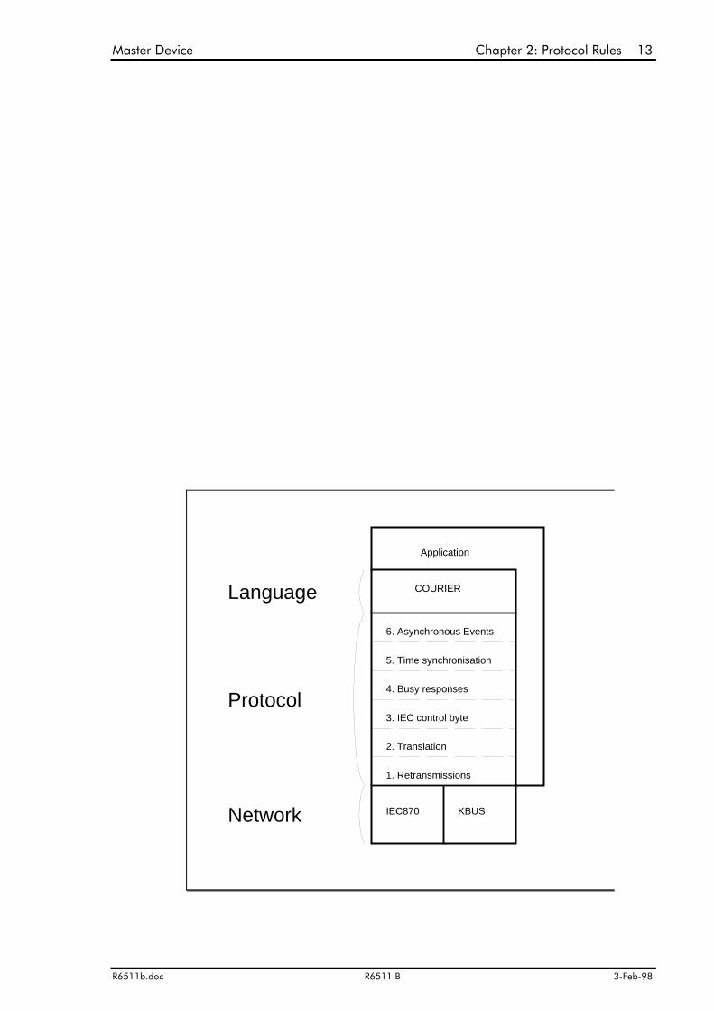
2.3. COURIER PROTOCOL OVERVIEW
(MASTER CONTROL UNIT)
Master Device Chapter 2: Protocol Rules 13
R6511b.doc R6511 B 3-Feb-98
KBUS
2. Translation
3. IEC control byte
5. Time synchronisation
Application
Network
Protocol
IEC870
1. Retransmissions
4. Busy responses
Language
6. Asynchronous Events
COURIER

14 Chapter 2: Protocol Rules Master Device
3-Feb-98 R6511 B R6511b.doc
The Courier Protocol in the master control unit is divided into 6 distinct layers. An applicationrequest formatted into a Courier message is passed into layer 6 of the protocol. This will usethe lower layers of the protocol to transmit the message and receive the response, which willbe returned from this layer back to the application. In the process of obtaining the responsefrom the slave device, other information may be extracted from the slave device such as: anyasynchronous events that may have occurred; changes in value to the plant status, plantcontrol words and changes to other flags in the Courier status byte; time synchronisationinformation and information relating to the communication status of the slave device. Theseare passed back to the application via other means rather than included with the response tothe original request; exactly how is determined by the application.
The protocol layers are described separately below.
Master Device Chapter 2: Protocol Rules 15
R6511b.doc R6511 B 3-Feb-98
2.3.1. LAYER 6: ASYNCHRONOUS EVENT LAYER.
Description
Input Request
Output Request
Input Response
Output Response
Direct Output
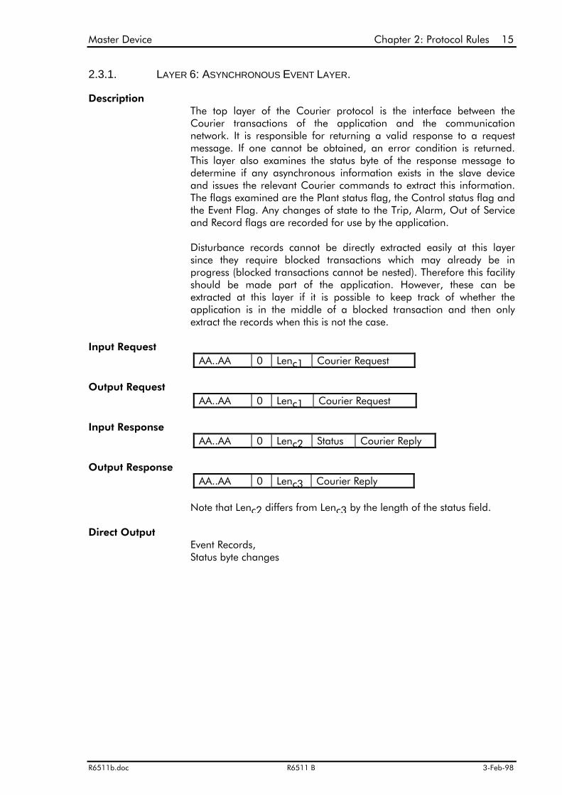
The top layer of the Courier protocol is the interface between theCourier transactions of the application and the communicationnetwork. It is responsible for returning a valid response to a requestmessage. If one cannot be obtained, an error condition is returned.This layer also examines the status byte of the response message todetermine if any asynchronous information exists in the slave deviceand issues the relevant Courier commands to extract this information.The flags examined are the Plant status flag, the Control status flag andthe Event Flag. Any changes of state to the Trip, Alarm, Out of Serviceand Record flags are recorded for use by the application.
Disturbance records cannot be directly extracted easily at this layersince they require blocked transactions which may already be inprogress (blocked transactions cannot be nested). Therefore this facilityshould be made part of the application. However, these can beextracted at this layer if it is possible to keep track of whether theapplication is in the middle of a blocked transaction and then onlyextract the records when this is not the case.
AA..AA 0 Lenc1 Courier Request
AA..AA 0 Lenc1 Courier Request
AA..AA 0 Lenc2 Status Courier Reply
AA..AA 0 Lenc3 Courier Reply
Note that Lenc2 differs from Lenc3 by the length of the status field.
Event Records,Status byte changes
16 Chapter 2: Protocol Rules Master Device
3-Feb-98 R6511 B R6511b.doc
2.3.2. LAYER 5: TIME SYNCHRONISATION LAYER.
Description
Input Request
Output Request
Input Response
Output Response
Direct Output
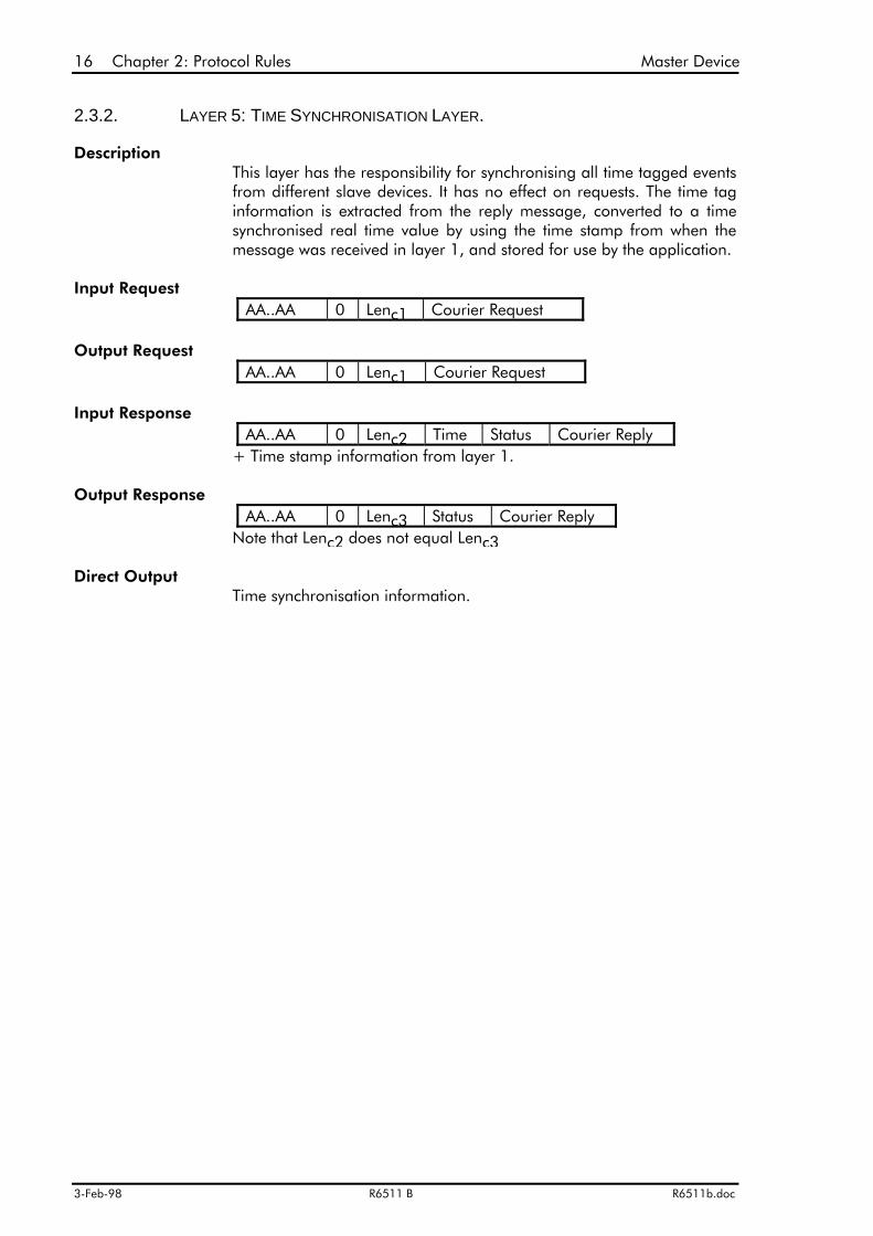
This layer has the responsibility for synchronising all time tagged eventsfrom different slave devices. It has no effect on requests. The time taginformation is extracted from the reply message, converted to a timesynchronised real time value by using the time stamp from when themessage was received in layer 1, and stored for use by the application.
AA..AA 0 Lenc1 Courier Request
AA..AA 0 Lenc1 Courier Request
AA..AA 0 Lenc2 Time Status Courier Reply+ Time stamp information from layer 1.
AA..AA 0 Lenc3 Status Courier ReplyNote that Lenc2 does not equal Lenc3
Time synchronisation information.

Master Device Chapter 2: Protocol Rules 17
R6511b.doc R6511 B 3-Feb-98
2.3.3. LAYER 4: BUSY RESPONSE LAYER.
Description
Input Request
Output Request
Input Response
Output Response
Direct Output
Busy Timeout
Optimization
This layer is responsible for returning a valid response to a request. Aslave device must return a response within a set response time. If itcannot form its reply within this time, it will return a message with anempty courier reply field and the Busy flag set in the status byte. Ondetection of a set Busy flag, this layer will send the Poll Buffer commandto the slave device. When a valid response is returned with the Busyflag clear, the response will be passed to the next higher level.
AA..AA 0 Lenc Courier Request
AA..AA 0 Lenc Courier RequestOR
AA..AA 0 Lenc Poll Buffer
AA..AA 0 Lenc Time Status (busy set)OR
AA..AA 0 Lenc Time Status Courier Reply
AA..AA 0 Lenc Time Status Courier Reply
None
A facility to break out of this layer and return an error code should beprovided for the condition of a slave device continuously returning aBusy response. This may take the form of a maximum number of busyresponses or a time limit for returning a non-busy response. This is toprevent a lock-up situation from occurring in the master control unit.
If a device returns a busy response, continual issuing of the Poll Buffercommand will slow down the overall response time since the device willbe spending most of its time responding to the Poll Buffer commandinstead of processing the original request. To fully utilize thecommunication bandwidth, it is advantageous to interleave requests toother devices during a device's busy period. This complicates thecommunication routines as it means queuing messages for each deviceseparately and working in a parallel manner, but results in a dramaticincrease in overall communication throughput.
18 Chapter 2: Protocol Rules Master Device
3-Feb-98 R6511 B R6511b.doc
2.3.4. LAYER 3: IEC CONTROL LAYER.
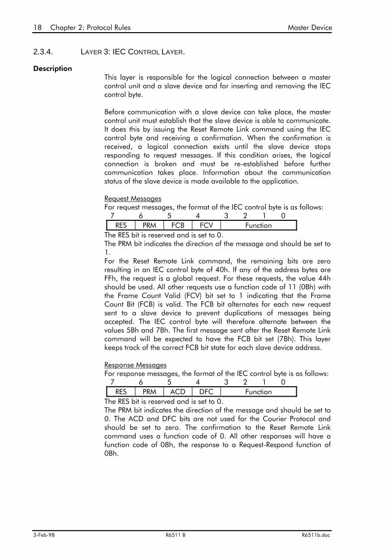
DescriptionThis layer is responsible for the logical connection between a mastercontrol unit and a slave device and for inserting and removing the IECcontrol byte.
Before communication with a slave device can take place, the mastercontrol unit must establish that the slave device is able to communicate.It does this by issuing the Reset Remote Link command using the IECcontrol byte and receiving a confirmation. When the confirmation isreceived, a logical connection exists until the slave device stopsresponding to request messages. If this condition arises, the logicalconnection is broken and must be re-established before furthercommunication takes place. Information about the communicationstatus of the slave device is made available to the application.
Request MessagesFor request messages, the format of the IEC control byte is as follows:
7 6 5 4 3 2 1 0RES PRM FCB FCV Function
The RES bit is reserved and is set to 0.The PRM bit indicates the direction of the message and should be set to1.For the Reset Remote Link command, the remaining bits are zeroresulting in an IEC control byte of 40h. If any of the address bytes areFFh, the request is a global request. For these requests, the value 44hshould be used. All other requests use a function code of 11 (0Bh) withthe Frame Count Valid (FCV) bit set to 1 indicating that the FrameCount Bit (FCB) is valid. The FCB bit alternates for each new requestsent to a slave device to prevent duplications of messages beingaccepted. The IEC control byte will therefore alternate between thevalues 5Bh and 7Bh. The first message sent after the Reset Remote Linkcommand will be expected to have the FCB bit set (7Bh). This layerkeeps track of the correct FCB bit state for each slave device address.
Response MessagesFor response messages, the format of the IEC control byte is as follows:
7 6 5 4 3 2 1 0RES PRM ACD DFC Function
The RES bit is reserved and is set to 0.The PRM bit indicates the direction of the message and should be set to0. The ACD and DFC bits are not used for the Courier Protocol andshould be set to zero. The confirmation to the Reset Remote Linkcommand uses a function code of 0. All other responses will have afunction code of 08h, the response to a Request-Respond function of0Bh.
Master Device Chapter 2: Protocol Rules 19
R6511b.doc R6511 B 3-Feb-98
Input Request
Output Request
Input Response
Output Response
Direct Output
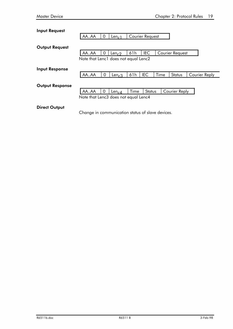
AA..AA 0 Lenc1 Courier Request
AA..AA 0 Lenc2 61h IEC Courier RequestNote that Lenc1 does not equal Lenc2
AA..AA 0 Lenc3 61h IEC Time Status Courier Reply
AA..AA 0 Lenc4 Time Status Courier ReplyNote that Lenc3 does not equal Lenc4
Change in communication status of slave devices.

20 Chapter 2: Protocol Rules Master Device
3-Feb-98 R6511 B R6511b.doc
2.3.5. LAYER 2: TRANSLATION LAYER.
Description
Input Request
Output Request
Input Response
Output Response
Direct Output
Notes
The translation layer rearranges the order and adjusts some of thevarious message fields for correct transmission over the network. Thetranslation layer will typically be different for each type of network used.
AA..AA 0 Lenc 61h IEC Courier Request
IEC870 format:Leni IEC AA..AA 0 Courier Request
KBUS format:AA..AA 0 Lenc 61h IEC Courier Request
IEC870 format:Leni IEC AA..AA 0 Time Status Courier Reply
KBUS format:AA..AA 0 Lenc 61h IEC Time Status Courier Reply
AA..AA 0 Lenc 61h IEC Time Status Courier Reply
None
The translation layer is non-existent for a KBUS network since themessage format is the same. However, for an IEC870 network, the IECcontrol byte and the length byte move position. Note also that thelength byte is stored in the IEC870 header and must be adjusted toinclude the length of the address field and the removed byte of 61h.
Master Device Chapter 2: Protocol Rules 21
R6511b.doc R6511 B 3-Feb-98
2.3.6. LAYER 1: RETRANSMISSION LAYER.
Description
Time-out Period
Number of Retries
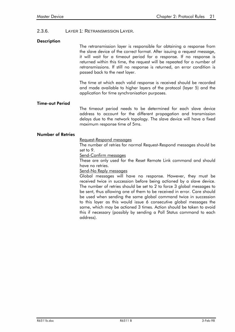
The retransmission layer is responsible for obtaining a response fromthe slave device of the correct format. After issuing a request message,it will wait for a timeout period for a response. If no response isreturned within this time, the request will be repeated for a number ofretransmissions. If still no response is returned, an error condition ispassed back to the next layer.
The time at which each valid response is received should be recordedand made available to higher layers of the protocol (layer 5) and theapplication for time synchronisation purposes.
The timeout period needs to be determined for each slave deviceaddress to account for the different propagation and transmissiondelays due to the network topology. The slave device will have a fixedmaximum response time of 5ms.
Request-Respond messagesThe number of retries for normal Request-Respond messages should beset to 9.Send-Confirm messages These are only used for the Reset Remote Link command and shouldhave no retries.Send-No Reply messagesGlobal messages will have no response. However, they must bereceived twice in succession before being actioned by a slave device.The number of retries should be set to 2 to force 3 global messages tobe sent, thus allowing one of them to be received in error. Care shouldbe used when sending the same global command twice in successionto this layer as this would issue 6 consecutive global messages thesame, which may be actioned 3 times. Action should be taken to avoidthis if necessary (possibly by sending a Poll Status command to eachaddress).
22 Chapter 2: Protocol Rules Master Device
3-Feb-98 R6511 B R6511b.doc
The flow of messages and information between the master control unit Courier protocol layerscan be illustrated in the following diagram:

Master Device Chapter 2: Protocol Rules 23
R6511b.doc R6511 B 3-Feb-98
CommStatus
Event
Response
Time Stamp
Accept Event
Ok
Response
Send Event
Event response
Time
Courier Request
Application 6. 5. 4.
Time Stamp
TIME
Confirmation
Busy Response
Poll Buffer
Reset Remote Link
3. 2.
Retry
Retry
Network1.
24 Chapter 2: Protocol Rules Master Device
3-Feb-98 R6511 B R6511b.doc
A logical connection is made to the slave device by layer 3 issuing a Reset Remote Linkcommand. Layer 3 identifies that the slave device is present at that address and makes thiscommunication status information available to the application.
A Courier request is then made by the application. Layer 1 retries the request and obtains aresponse. Layer 4 detects that this is a busy response and issues a Poll Buffer request, whichagain Layer 1 has to retry before it receives a response.
The response is a valid Courier response to the initial request and layer 5 performs any timesynchronisation required. Layer 6 detects that an event has taken place in the slave device. Ittherefore issues a Send Event Command. The slave device returns the event straight away andagain Layer 5 performs any time synchronisation required. Layer 6 then issues the AcceptEvent command and the slave device returns OK. The event is stored for use by theapplication
Layer 6 finally returns the slave device's response to the initial application request.

Slave Device Chapter 2: Protocol Rules 25
R6511b.doc R6511 B 3-Feb-98
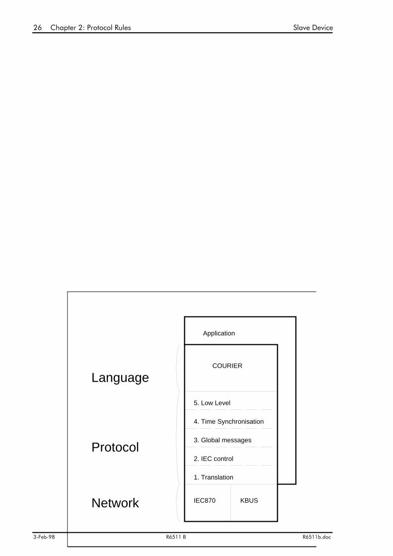
2.4. COURIER PROTOCOL OVERVIEW
(SLAVE DEVICE)
26 Chapter 2: Protocol Rules Slave Device
3-Feb-98 R6511 B R6511b.doc
KBUS
Application
5. Low Level
4. Time Synchronisation
3. Global messages
2. IEC control
1. Translation
Network
Protocol
IEC870
LanguageCOURIER
Slave Device Chapter 2: Protocol Rules 27
R6511b.doc R6511 B 3-Feb-98
The Courier Protocol in the slave device is divided into 5 distinct layers and works in thereverse manner to the protocol layers in the master control unit. A request message is receivedby layer 1 of the protocol and successively passed up through the layers to the application.This may then respond by returning a Courier response message to layer 5 which is thenpassed back through the layers to the communication network.
Some of the lower layers (1-3) may be performed by the network itself but are included herefor those networks which do not inherently perform these functions.
The protocol layers are described separately below in the reverse order to the layers in themaster control unit so that the flow of messages can be more easily followed.
28 Chapter 2: Protocol Rules Slave Device
3-Feb-98 R6511 B R6511b.doc
2.4.1. LAYER 1: TRANSLATION LAYER.
Description
Input Request
Output Request
Input Response
Output Response
Direct Output
Notes
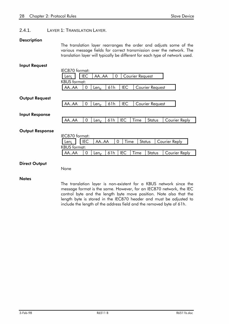
The translation layer rearranges the order and adjusts some of thevarious message fields for correct transmission over the network. Thetranslation layer will typically be different for each type of network used.
IEC870 format:Leni IEC AA..AA 0 Courier Request
KBUS format:AA..AA 0 Lenc 61h IEC Courier Request
AA..AA 0 Lenc 61h IEC Courier Request
AA..AA 0 Lenc 61h IEC Time Status Courier Reply
IEC870 format:Leni IEC AA..AA 0 Time Status Courier Reply
KBUS format:AA..AA 0 Lenc 61h IEC Time Status Courier Reply
None
The translation layer is non-existent for a KBUS network since themessage format is the same. However, for an IEC870 network, the IECcontrol byte and the length byte move position. Note also that thelength byte is stored in the IEC870 header and must be adjusted toinclude the length of the address field and the removed byte of 61h.
Slave Device Chapter 2: Protocol Rules 29
R6511b.doc R6511 B 3-Feb-98
2.4.2. LAYER 2: IEC CONTROL LAYER.
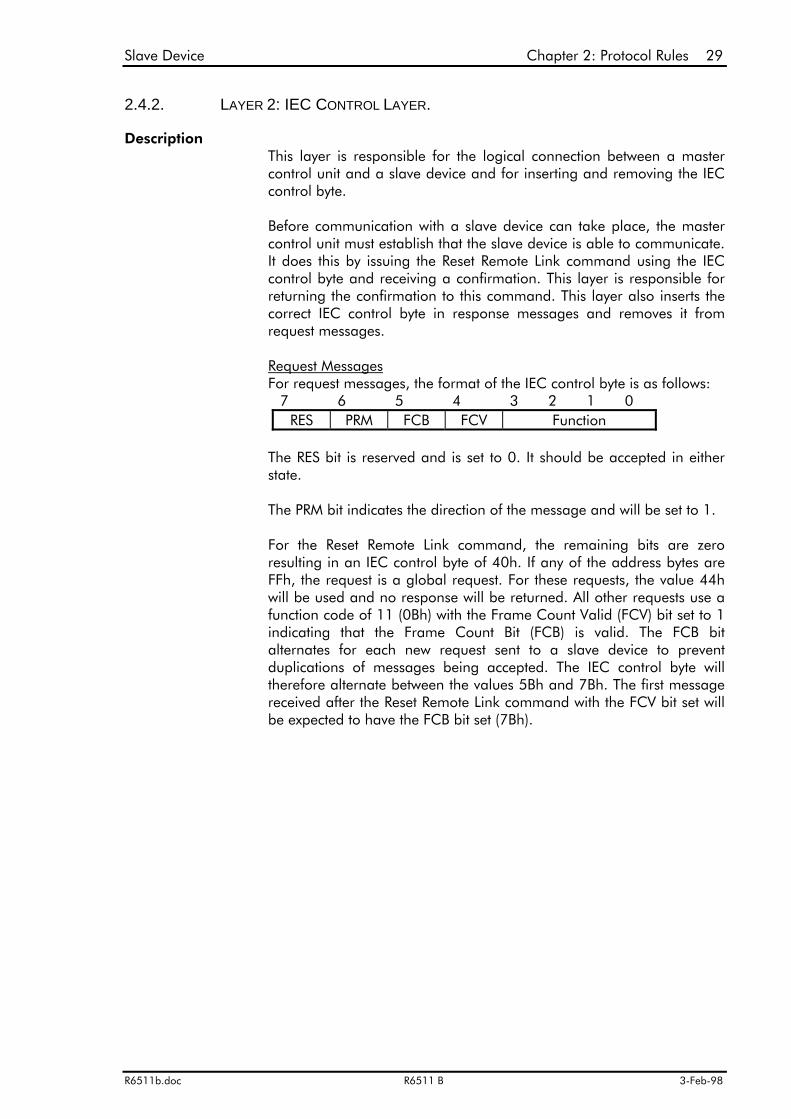
DescriptionThis layer is responsible for the logical connection between a mastercontrol unit and a slave device and for inserting and removing the IECcontrol byte.
Before communication with a slave device can take place, the mastercontrol unit must establish that the slave device is able to communicate.It does this by issuing the Reset Remote Link command using the IECcontrol byte and receiving a confirmation. This layer is responsible forreturning the confirmation to this command. This layer also inserts thecorrect IEC control byte in response messages and removes it fromrequest messages.
Request MessagesFor request messages, the format of the IEC control byte is as follows:
7 6 5 4 3 2 1 0RES PRM FCB FCV Function
The RES bit is reserved and is set to 0. It should be accepted in eitherstate.
The PRM bit indicates the direction of the message and will be set to 1.
For the Reset Remote Link command, the remaining bits are zeroresulting in an IEC control byte of 40h. If any of the address bytes areFFh, the request is a global request. For these requests, the value 44hwill be used and no response will be returned. All other requests use afunction code of 11 (0Bh) with the Frame Count Valid (FCV) bit set to 1indicating that the Frame Count Bit (FCB) is valid. The FCB bitalternates for each new request sent to a slave device to preventduplications of messages being accepted. The IEC control byte willtherefore alternate between the values 5Bh and 7Bh. The first messagereceived after the Reset Remote Link command with the FCV bit set willbe expected to have the FCB bit set (7Bh).
30 Chapter 2: Protocol Rules Slave Device
3-Feb-98 R6511 B R6511b.doc
Input Request
Output Request
Input Response
Output Response
Direct Output
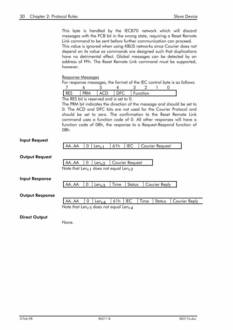
This byte is handled by the IEC870 network which will discardmessages with the FCB bit in the wrong state, requiring a Reset RemoteLink command to be sent before further communication can proceed. This value is ignored when using KBUS networks since Courier does notdepend on its value as commands are designed such that duplicationshave no detrimental effect. Global messages can be detected by anaddress of FFh. The Reset Remote Link command must be supported,however.
Response MessagesFor response messages, the format of the IEC control byte is as follows:
7 6 5 4 3 2 1 0RES PRM ACD DFC Function
The RES bit is reserved and is set to 0.The PRM bit indicates the direction of the message and should be set to0. The ACD and DFC bits are not used for the Courier Protocol andshould be set to zero. The confirmation to the Reset Remote Linkcommand uses a function code of 0. All other responses will have afunction code of 08h, the response to a Request-Respond function of0Bh.
AA..AA 0 Lenc1 61h IEC Courier Request
AA..AA 0 Lenc2 Courier RequestNote that Lenc1 does not equal Lenc2
AA..AA 0 Lenc3 Time Status Courier Reply
AA..AA 0 Lenc4 61h IEC Time Status Courier ReplyNote that Lenc3 does not equal Lenc4
None.
Slave Device Chapter 2: Protocol Rules 31
R6511b.doc R6511 B 3-Feb-98
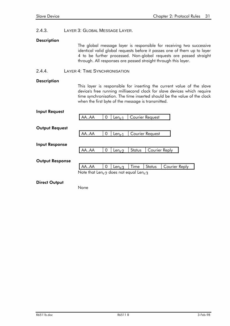
2.4.3. LAYER 3: GLOBAL MESSAGE LAYER.
Description
2.4.4. LAYER 4: TIME SYNCHRONISATION
Description
Input Request
Output Request
Input Response
Output Response
Direct Output
The global message layer is responsible for receiving two successiveidentical valid global requests before it passes one of them up to layer4 to be further processed. Non-global requests are passed straightthrough. All responses are passed straight through this layer.
This layer is responsible for inserting the current value of the slavedevice's free running millisecond clock for slave devices which requiretime synchronisation. The time inserted should be the value of the clockwhen the first byte of the message is transmitted.
AA..AA 0 Lenc1 Courier Request
AA..AA 0 Lenc1 Courier Request
AA..AA 0 Lenc2 Status Courier Reply
AA..AA 0 Lenc3 Time Status Courier ReplyNote that Lenc2 does not equal Lenc3
None
32 Chapter 2: Protocol Rules Slave Device
3-Feb-98 R6511 B R6511b.doc
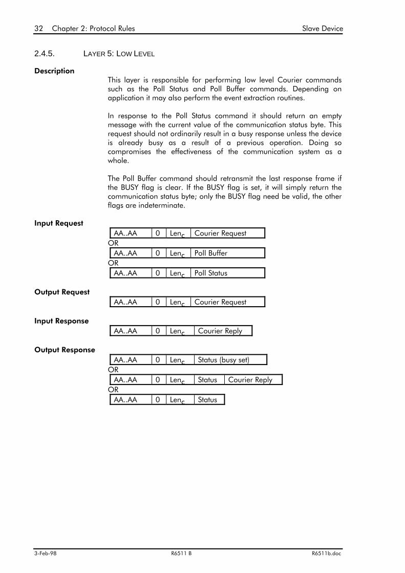
2.4.5. LAYER 5: LOW LEVEL
Description
Input Request
Output Request
Input Response
Output Response
This layer is responsible for performing low level Courier commandssuch as the Poll Status and Poll Buffer commands. Depending onapplication it may also perform the event extraction routines.
In response to the Poll Status command it should return an emptymessage with the current value of the communication status byte. Thisrequest should not ordinarily result in a busy response unless the deviceis already busy as a result of a previous operation. Doing socompromises the effectiveness of the communication system as awhole.
The Poll Buffer command should retransmit the last response frame ifthe BUSY flag is clear. If the BUSY flag is set, it will simply return thecommunication status byte; only the BUSY flag need be valid, the otherflags are indeterminate.
AA..AA 0 Lenc Courier RequestOR
AA..AA 0 Lenc Poll BufferOR
AA..AA 0 Lenc Poll Status
AA..AA 0 Lenc Courier Request
AA..AA 0 Lenc Courier Reply
AA..AA 0 Lenc Status (busy set)OR
AA..AA 0 Lenc Status Courier ReplyOR
AA..AA 0 Lenc Status
Slave Device Chapter 2: Protocol Rules 33
R6511b.doc R6511 B 3-Feb-98
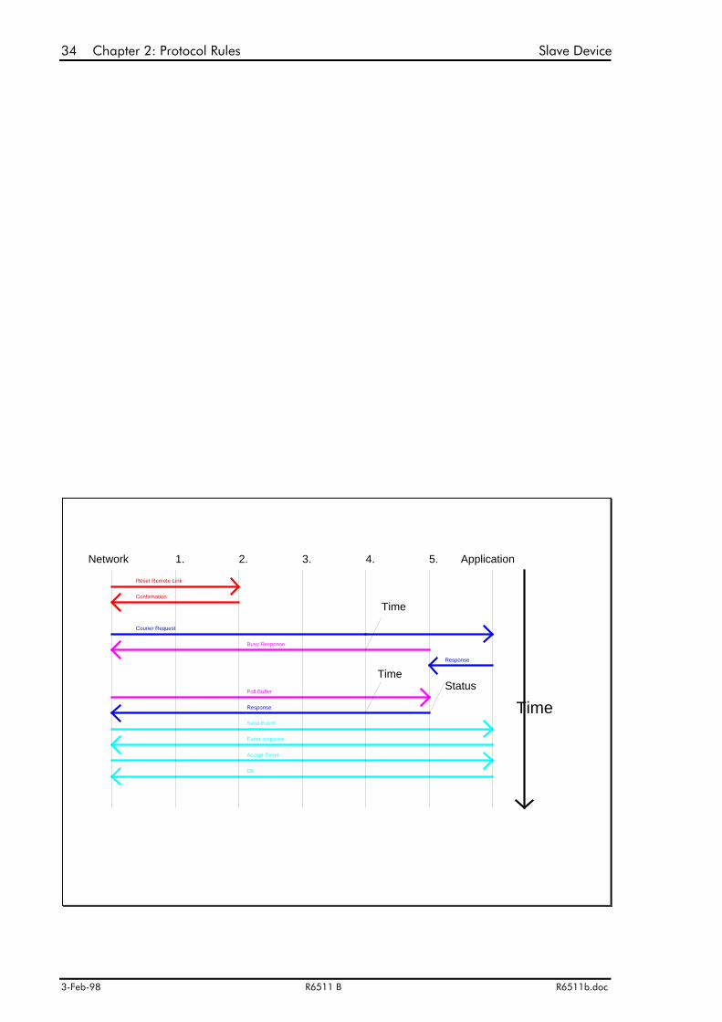
The flow of messages and information between the slave device Courier protocol layers canbe illustrated in the following diagram:
34 Chapter 2: Protocol Rules Slave Device
3-Feb-98 R6511 B R6511b.doc
Response
Send Event
Event response
Accept Event
Ok
Courier Request
Network 1.
Reset Remote Link
Confirmation
Poll Buffer
Busy Response
2. 3.
Time
Application
Response
Status
Time
Time
4. 5.

Slave Device Chapter 2: Protocol Rules 35
R6511b.doc R6511 B 3-Feb-98
A reset remote link command is received which Layer 2 intercepts and returns a confirmation.
A Courier request is then received which is passed to the application layer. Layer 5 does notreceive a response from the application within the 5ms time out period and so it returns abusy response to the network.
The busy response prompts a Poll Buffer command which is handled by layer 5. By this timethe application has returned a response, so this is returned as the reply to the Poll Buffercommand with the current status byte (otherwise another Busy response would have beenreturned).
Because the event bit was set in the previous response, the master control unit then issues asend event command. The application returns the event response. This is acknowledged withan accept command which clears the event flag (as there are no more events) and theapplication returns an OK reply code.
In all responses, the status byte is added at layer 6, the time is added at layer 5 and the IECcontrol byte is added at layer 2.

36 Chapter 2: Protocol Rules
3-Feb-98 R6511 B R6511b.doc
2.5. IEC CONTROL FIELD
The IEC870 Control field consists of 2 bytes. The first is 61h to identify the field whilst thesecond contains information that characterises the direction of the message, the type of serviceprovided and supports control functions for suppressing the losses or duplication of messages.This is described as the IEC870 control byte in the IEC870-5-2 5.1.2 specification.
There are three service classes which are described in the following table:
The format of the IEC870 control byte is as follows:
RES: Reserved.This bit is reserved. It should be transmitted as a 0, but should be accepted in either a 0 or a 1state.
PRM: Primary message.Indicates the direction of the message, 1 for master to slave messages, 0 for slave to mastermessages.
FCB: Frame Count Bit.An alternating bit 0/1 for successive SEND/CONFIRM or REQUEST/RESPOND services perslave device. The Frame Count bit is used for suppressing the duplications of informationtransfers: The master control unit alternates the FCB bit for each new SEND/CONFIRM orREQUEST/RESPOND transmission service directed to the same slave device. Thus the mastercontrol unit keeps a copy of the Frame Count Bit per slave device. If an expected reply istimed-out (missing) or garbled, then the same SEND/CONFIRM or REQUEST/RESPONDservice is repeated with the same FCB state.
The FCB bit is always zero for reset commands. After a reset command, the slave device willexpect the next message received from the master control unit with the FCV bit set to have theFCB bit set also.
Link Service Class Function ExplanationS1 SEND/NO REPLY Transmit message; neither
acknowledgement nor answer isrequested within the link layer.
S2 SEND/CONFIRM Transmit message; acknowledgement isrequested within the link layer.
S3 REQUEST/RESPOND Transmit message; a response isrequested within the link layer; theresponse will contain data.
Link service classes.
7 6 5 4 3 2 1 0RES PRM=1 FCB FCV Function Master---->Slave
=0 ACD DFC Slave---->MasterIEC870 control byte format.

Chapter 2: Protocol Rules 37
R6511b.doc R6511 B 3-Feb-98
FCV: Frame Count Valid.0 = alternating function of FCB bit is invalid.1 = alternating function of FCB bit is valid.SEND/NO REPLY service, broadcast messages and other transmission services that ignore thesuppression of duplication or loss of information output do not alternate the FCB bit andindicate this by a cleared FCV bit.
DFC: Data Flow Control.This bit is reserved and should be set to 0.
ACD: Access Demand.This bit is reserved and should be set to 0.
Functions.The only functions that are used in the K-Bus environment are shown below:
Function Frame Type Service Function Use FCV0 Send-Confirm
(class S2)Reset Remote Link Resetting and identifying
slave devices.0
4 Send-No reply(class S1)
User Data Global Messages 0
11 Request-Respond(class S3)
Request UserData Class 2
Normal K-Bus Request 1
IEC870 function codes for request frames.
Function Frame Type Service Function Use0 Confirm
(class S2)ACK: Positiveacknowledgement ofReset Remote Link
Indicates slave device ispresent.
8 Respond(class S3)
User Data Normal K-Bus Response
IEC870 function codes for response frames.

38 Chapter 2: Protocol Rules
3-Feb-98 R6511 B R6511b.doc
Chapter 3: Automatic Data Retrieval 39
R6511b.doc R6511 B 3-Feb-98
Chapter 3: Automatic Data Retrieval
Courier is designed to operate using a polled system, which prevents a slave device fromcommunicating directly to a master control unit when it needs to inform it that something hashappened; it must wait until it is asked by the master control unit. If the master control unitcontinually asks a slave device for lots of information just in case something has happened,the communication system will be inefficient.
The status byte of a Courier message allows the slave device to inform the master control unitthat it contains additional information to be extracted and to indicate changes of state ofimportant data.
3.1. EVENT RECORDS
The Event record is a mechanism that has been designed to allow a master control unit toextract this type of unsolicited information from a slave device quickly and efficiently.
An event record is designed to be a short, concise description of an event which has occurredin a slave device which the master control unit should know about. It includes suchoccurrences as local setting changes, logic input changes, relay output changes and trips.When such an event occurs, the slave device prepares an appropriate message to betransmitted and sets the EVENT bit in the Courier status byte which is transmitted in each andevery reply to the master control unit.
The extraction of an event record is considered a high priority task by a master control unitwhich it will perform as soon as it recognises the event bit of the slave device being set and theslave device has returned a valid response to the last request and not a busy message. Thismay occur at any time. The extraction of an event is a grouped transaction. It cannot be ablocked transaction because a blocked transaction may already be in progress and blockedtransactions cannot be nested. It therefore follows that a complete event record must fit intoone response message.
All event groups must begin with a standard packet format as outlined below:

40 Chapter 3: Automatic Data Retrieval
3-Feb-98 R6511 B R6511b.doc
Packet# DTL Use1 46h Menu cell reference2 38h/3Ch Time tag3 18h+LL ASCII Text description4 xx Menu cell value
This is described more fully in the Courier User Guide.
Once the event bit is seen as being set, the master control unit issues a Send Event Command.The slave device may respond with a busy message, an error code or a grouped event record.An error code 2 may occur if there are events waiting to be extracted but the oldest event isnot currently accessible. The Send Event command should be re-issued until a valid eventrecord is extracted. The Poll Buffer command is issued if a busy response is returned.
After a valid event has been extracted, the Send Event command would continue extracting thesame event unless the slave device is informed that the master control unit has received thelast event record. This is done by the master control unit issuing the Accept Event commandonce a valid event record has been extracted. On receipt of this command, the slave devicewill discard the last event that it sent and determine if any more events are stored. If there areno more events to be extracted, the slave device will reset its event bit. If there are still someevents left, the event bit remains set. The slave device then returns a reply code of 0 (ERR_OK)to indicate that it has discarded the last event.
Courier specifies an automatic retry of commands which have not resulted in a reply within aspecified time-out period. This may result in repeated Accept Event or Send Event commands ifthe replies are not received correctly. To prevent these repetitions from discarding eventswhich the master control unit has not received correctly, these commands must be interlacedwith each other. Repeated Accept Event commands will therefore only discard one event.Repeated Send Event commands will result in the same event being transmitted.
The actual implementation of event records in the slave device is application dependent. Theextraction procedure outlined above assumes that event records are lost on loss of power tothe slave device and that once discarded they may not be retrieved again. This in fact may notbe the case as some slave devices may decide to store all or some of their event records innon-volatile memory. In this instance, additional commands may be sent to the slave device(e.g. changing the value of a setting cell) to make previously discarded event records availableagain.
3.2. PLANT STATUS WORD
The plant status word is a pre-defined binary word containing information about the state ofvarious pre-defined items of plant which may be controlled by the slave device. It can befound at a reserved location in the system data column of the slave device's database. Eachitem of plant uses 2 bits in this word, the meaning of which is shown below:
High bit Low bit Meaning0 0 Not fitted0 1 Open1 0 Closed1 1 Not fitted

Chapter 3: Automatic Data Retrieval 41
R6511b.doc R6511 B 3-Feb-98
On average there are three controllable isolators per circuit breaker, so the bit pairs arearranged as 1 circuit breaker and 3 isolators per byte as follows:
bit 31 bit 0---- ---- ---- ---- ---- ---- ---- --XX Circuit Breaker 1---- ---- ---- ---- ---- ---- ---- XX-- Isolator 1---- ---- ---- ---- ---- ---- --XX ---- Isolator 2---- ---- ---- ---- ---- ---- XX-- ---- Isolator 3---- ---- ---- ---- ---- --XX ---- ---- Circuit Breaker 2---- ---- ---- ---- ---- XX-- ---- ---- Isolator 4---- ---- ---- ---- --XX ---- ---- ---- Isolator 5---- ---- ---- ---- XX-- ---- ---- ---- Isolator 6---- ---- ---- --XX ---- ---- ---- ---- Circuit Breaker 3---- ---- ---- XX-- ---- ---- ---- ---- Isolator 7---- ---- --XX ---- ---- ---- ---- ---- Isolator 8---- ---- XX-- ---- ---- ---- ---- ---- Isolator 9---- --XX ---- ---- ---- ---- ---- ---- Circuit Breaker 4---- XX-- ---- ---- ---- ---- ---- ---- Isolator 10--XX ---- ---- ---- ---- ---- ---- ---- Isolator 11XX-- ---- ---- ---- ---- ---- ---- ---- Isolator 12
The length of this word is variable depending on the number of circuit breakers and isidentified when the data is requested. However, 2 bytes will usually suffice.
3.3. CONTROL STATUS WORD
The control status word is a binary word used to interchange control information with themaster control unit and can be found at a reserved location in the system data column of theslave device's database. There are no specific definitions for the uses of the bits within thisword and each slave device is free to define them for its own uses. The master control unitwould need to be programmable to perform different actions depending on the state of thesebits for each slave device or type of slave device.
3.4. TRIP INDICATIONS
The trip flag is used to mimic a trip indication on the front of the slave device for annunciationpurposes. It cannot be used to extract fault information from a slave device because it cannotbe guaranteed to be set for a long enough period in order to be identified. Also it is notautomatically reset, and therefore may cause the same fault record to be read twice (or someto be missed if the master control unit does not see it clear and set again for a second trip).Fault information is sent using event records.
3.5. ALARM INDICATIONS
The alarm flag is used to mimic an alarm indication on the front of the slave device forannunciation purposes. It cannot be used to extract alarm information from a slave devicebecause it cannot be guaranteed to be set for a long enough period in order to be identified.Also it is not automatically reset, and therefore may cause the same alarm to be read twice (orsome to be missed if the master control unit does not see it clear and set again for a secondalarm). The alarm indication may flash on and off causing the alarm flag to set and clearrepeatedly. Alarm information should be sent via the event record mechanism.
42 Chapter 3: Automatic Data Retrieval
3-Feb-98 R6511 B R6511b.doc
Chapter 4: Time Synchronisation 43
R6511b.doc R6511 B 3-Feb-98
Chapter 4: Time Synchronisation
One of the important functions of existing SCADA systems is sequence of event recording. Thisgives the system engineer valuable insight into the order in which events on the system occur.The typical accuracy of existing systems ranges from ±10ms to ±1ms. This function is currentlycarried out by the RTU's of the SCADA system which monitor system events using digitalinputs. These events are generally time tagged using a system synchronising pulse distributedaround the communication network. Often of more importance than the absolute time of anevent is its time relative to other events across the system.
Two possible methods of time tagging are provided in the Courier Protocol. The first allowseach slave device to have its own real time clock synchronised to the rest of the system. Timetagged events are logged by recording this time in IEC time & date format and transmittingthis information with the event. However, using multiple real time clocks can be expensive andrequires them all to be synchronised externally.
An alternative method of time synchronisation has been devised which removes the need forseparate clock synchronisation wiring. Rather than trying to synchronise the clocks within eachindividual slave device, the clocks are allowed to free run. Events within each slave device aretime tagged relative to the internal free running clock. This is derived from themicroprocessors clock and resolutions of ±1ms are easily obtained.
Clearly when these event records are transmitted to the master control unit, events fromdifferent slave devices will be out of step. This problem is solved by also transmitting thecurrent value of the slave device's clock. This is compared with the master control unit's clockand the difference used to calculate the actual time of the event.
Consider a system with a master control unit whose clock Tc is synchronised to real time. Aslave device on the system has a clock Tr which is not synchronised. At any particular instancein time we can say that:
Tc = Tr + ∆t
where ∆t is the difference between the two timers. Thus if an event is seen by the slave deviceat time Tr1, then the synchronised time at which it actually occurred Tc1 is given by:
Tc1 = Tr1 + ∆t1 (1)

44 Chapter 4: Time Synchronisation
3-Feb-98 R6511 B R6511b.doc
where ∆t1 is the difference between the timers at the instance of the fault. At some time later,Tr2 (equivalent to Tc2-∆t2) the slave device transmits the time of the event (Tr1) together withits current time Tr2. This is received by the master control unit at time Tc2 + tp, where tp isthe propagation delay down the communications channel. At this point we can say:
Tc2 = Tr2 + ∆t2 - tp (2)
The time tp can be calculated from a knowledge of the message length and the baud rate,however, using a KBUS based network it is insignificant compared with the 1ms accuracy of Tcand Tr. The difference between ∆t1 and ∆t2 is the rate of drift between the two clocks. Both ofthese clocks are derived from quartz crystals or better and hence even over several hours wecan say:
∆t1 = ∆t2
Equation 2 can therefore be simplified and rearranged to give:
∆t1 = ∆t2 = Tc2 - Tr2
This knowledge of ∆t1 is then used in equation 1 to calculate the actual time of the event Tc1:
Tc1 = Tr1 + Tc2 - Tr2
This time synchronisation method can only be used on systems where the speed oftransmission is fast compared to the timing resolution required and where the transmissiontimes are consistent (such as KBUS) such that tp can be eliminated. On an IEC870 basedsystem, this cannot be guaranteed and therefore the slave devices would be better havingtheir own real time clocks.
Where a KBUS network is interfaced directly to an IEC870 network, the point of inter-connection will be a protocol converter. This would require its own real time clock to timestamp KBUS messages as they are received. This time is inserted into the message after theslave device's own clock value as an IEC time & date formatted packet. The timesynchronisation at the master control unit will use the protocol converter's time rather than itsown in order to align all time tagged events. The protocol converter's real time clock will needexternal synchronisation with all other real time clocks in the system.
DTL time Tag 4 byte millisecond DTL IEC870 Real-time(38h)+(04h) timer count value time & date time-tag
↑ ↑This data packet is only required if slavedevice has no real time clock
This data packet optionallyinserted by a protocolconverter.
The time synchronisation process generally produces a real time value adjusted by an offsetfor each slave device, which when added to a time tag in the Courier response message,converts the relative time to a time synchronised real time value. This offset real time value iscalculated in layers 1 and 5 of the master control unit and passed to the application by aseparate path so that it can be used when required.
Chapter 4: Time Synchronisation 45
R6511b.doc R6511 B 3-Feb-98
AMENDMENTS
Issue Date ChangesA 06/05/93 First IssueB 05/04/95 Changed fonts
12/04/95 CB position reversed.
Related Documents