VK VK VK VK VK ™ Veritical Cooling Comfort air conditioners (AVK-L30) Engineering Manual 3 to 30 Tons “Floor Mounted Comfort A/C’s” (Modular for Rigging Purposes!) Features & Benefits • 3 to 30 Ton Capacities • Comfort Applications - General Office Spaces - Retail Stores - Restuarants - Factories & Warehouses • Compact Vertical Floor Mounted SCAV Self-Contained & Split • DX Air, Water & Glycol Cooled, Heat Pumps & Economizers • Energy Saving Options - Variable Frequency Drives for VAV Applications - Air Side Economizers - Water Side Economizers • Modular for Rigging Purposes & . . . More! VK VK VK VK VK ™ 3-30 Tons Vertical Comfort Cooling A/C’s & Heat Pumps MEA229-06-E Approved R410a Da R410a Da R410a Da R410a Da R410a Data ta ta ta ta

Welcome message from author
This document is posted to help you gain knowledge. Please leave a comment to let me know what you think about it! Share it to your friends and learn new things together.
Transcript

AboveAir™ VK Vertical A/C’sAboveAir Technologies (AVK-L30)1
VKVKVKVKVK™ Veritical Cooling Comfort air conditioners (AVK-L30)
Engineering Manual
3 to 30 Tons“Floor Mounted Comfort A/C’s”(Modular for Rigging Purposes!)
Features & Benefits• 3 to 30 Ton Capacities
• Comfort Applications- General Office Spaces- Retail Stores- Restuarants- Factories & Warehouses
• Compact Vertical Floor MountedSCAV Self-Contained & Split
• DX Air, Water & Glycol Cooled,Heat Pumps & Economizers
• Energy Saving Options- Variable Frequency Drives for
VAV Applications- Air Side Economizers- Water Side Economizers
• Modular for Rigging Purposes &. . . More!
VKVKVKVKVK™ 3-30 TonsVertical Comfort Cooling
A/C’s & Heat Pumps
MEA229-06-E Approved
R410a DaR410a DaR410a DaR410a DaR410a Datatatatata

AboveAir™ VK Vertical A/C’s AboveAir Technologies (AVK-L30)2 Introduction
INTRODUCTION - VK™ Vertical SCAVAboAboAboAboAbovvvvveeeeeAirAirAirAirAir™™™™™ VK vertical floormounted air conditioners are thereliable solution to your comfortcooling control needs. Availablein a wide variety of cooling meth-ods and cabinet configurationsincluding a full range of options,AboAboAboAboAbovvvvveeeeeAirAirAirAirAir™™™™™ A/C’s are a stepabove!
R410a High Efficient Refrigerant
Modular For Rigging Purposes
Packaged & Split Systems
Top or Front Evap Air Discharge
Variety of cooling methods
Air Side and Water-Glycol Economizers
VAV / VFD Application Option
Flexible options and accessories
Energy efficient operation
Contents
Introduction ............................................... 2
Features and Benefits ............................... 3
Performance Data ................................... 4-8
Electrical Data ....................................... 8-11
Guide Specifications .......................... 12-17
Unit Dimensional Data ....................... 18-28
Glycol Drycoolers ............................... 29-30
Model Nomenclature ............................... 31
Top EvaporatorAir Discharge
Front EvaporatorAir Discharge
AboveAir™ VK Vertical A/C’sAboveAir Technologies (AVK-L30)3Features & Benefits
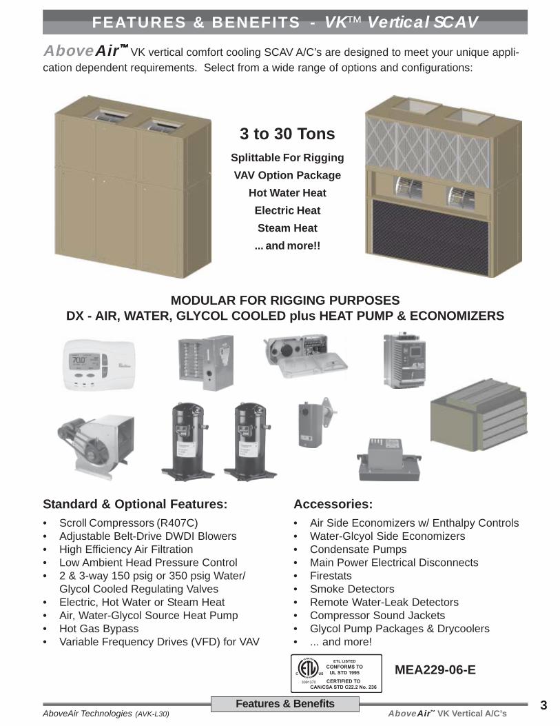
FEATURES & BENEFITS - VK™ Vertical SCAVAboveAir™™™™™ VK vertical comfort cooling SCAV A/C’s are designed to meet your unique appli-
cation dependent requirements. Select from a wide range of options and configurations:
Standard & Optional Features:
• Scroll Compressors (R407C)• Adjustable Belt-Drive DWDI Blowers• High Efficiency Air Filtration• Low Ambient Head Pressure Control• 2 & 3-way 150 psig or 350 psig Water/
Glycol Cooled Regulating Valves• Electric, Hot Water or Steam Heat• Air, Water-Glycol Source Heat Pump• Hot Gas Bypass• Variable Frequency Drives (VFD) for VAV
MODULAR FOR RIGGING PURPOSESDX - AIR, WATER, GLYCOL COOLED plus HEAT PUMP & ECONOMIZERS
Accessories:
• Air Side Economizers w/ Enthalpy Controls• Water-Glcyol Side Economizers• Condensate Pumps• Main Power Electrical Disconnects• Firestats• Smoke Detectors• Remote Water-Leak Detectors• Compressor Sound Jackets• Glycol Pump Packages & Drycoolers• ... and more!
3 to 30 TonsSplittable For Rigging
VAV Option Package
Hot Water Heat
Electric Heat
Steam Heat
... and more!!
MEA229-06-E

AboveAir™ VK Vertical A/C’s AboveAir Technologies (AVK-L30)4 Performance Data
Nominal Size 4 Tons 5 Tons 6 Tons 8 Tons 10 Tons
Air Cooled Model VKA/KE/KH-048 VKA/KE/KH-060 VKA/KE/KH-072 VKA/KE/KH-096 VKA/KE/KH-120
AIRCOOLED
DX
80°F DB / 67°F WB, 50% RH
Total BTUH 52,100 63,500 76,200 94,200 125,000
Sensible BTUH 36,400 45,300 55,500 70,700 94,000
75°F DB / 62.5°F WB, 50% RH
Total BTUH 47,800 58,600 70,000 86,600 115,000
Sensible BTUH 36,200 45,100 55,400 70,500 92,000
Water Cooled Model VKW-048 VKW-060 VKW-072 VKW-096 VKW-120
WATERCOOLED
DX
80°F DB / 67°F WB, 50% RH
Total BTUH 56,700 69,000 87,900 107,600 132,000
Sensible BTUH 39,300 48,800 62,100 77,200 97,600
75°F DB / 62.5°F WB, 50% RH
Total BTUH 51,400 63,800 80,100 97,700 126,800
Sensible BTUH 38,700 46,400 61,000 75,700 103,400
Glycol Cooled Model VKG-048 VKG-060 VKG-072 VKG-096 VKG-120
GLYCOLCOOLED
DX
80°F DB / 67°F WB, 50% RH
Total BTUH 49,100 60,100 75,700 92,700 115,800
Sensible BTUH 36,400 45,200 57,100 71,400 85,600
75°F DB / 62.5°F WB, 50% RH
Total BTUH 44,500 54,800 68,400 83,900 105,300
Sensible BTUH 35,500 44,200 55,900 69,900 83,900
GENERAL SHARED DATA
ALL DXMODELS
Electric Heater (Duct Mounted, Separately Powered) - BTUH includes evaporator motor heat, (Optional)
CapacityBTUH 52,915 53,490 54,630 55,780 75,135
KW 15.0 15.0 15.0 15.0 20.0
Stages NO 2 2 2 2 2
Evaporator Blower / Motor - Belt Drive, DWDI Centrifugal
Airflow Rate CFM 1,600 2,000 2,400 3,200 4,000
E.S.P. IN WG 0.75 0.75 0.75 0.75 0.75
Blower Motor HP 3/4 1 1.5 2 3
Blower Diameter IN 12 X 9 12 X 9 12 X 9 15 X 10 15 X 10
Evaporator Coil - Aluminum Fin, Copper Tube
Rows NO 4 4 4 4 4
Face Area FT2 5.1 5.1 5.1 8.6 8.6
Filters - 30% Dust Spot Efficient
Nominal Size (NO) IN (2) 16 x 24 x 2 (2) 16 x 24 x 2 (2) 16 x 24 x 2 (3) 16 x 25 x 2 (3) 16 x 25 x 2
Compressor - Heat Pump Duty Hermetic
Qty., Horespower (NO) HP (1) 4.0 (1) 5.0 (1) 6.0 (2) 4.0 (2) 5.0
Connection Sizes
Condensate Drain FPT IN 3/4 3/4 3/4 3/4 3/4
Approximate Unit Weights
VKA-( ) LBS 900 925 930 1,200 1,225
VKE-( ) LBS 800 825 830 1,050 1,075
VKH-( ) LBS 700 725 730 900 925
VKW & VKG-( ) LBS 850 875 880 1,100 1,125
Performance Data (VK-Vertical) - DX 4 To 10 Tons
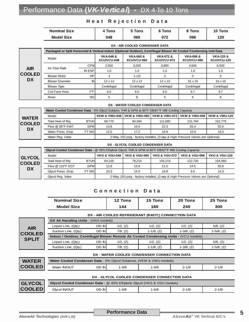
AboveAir™ VK Vertical A/C’sAboveAir Technologies (AVK-L30)5Performance Data
Performance Data (VK-Vertical) - DX 4 To 10 Tons
H e a t R e j e c t i o n D a t a
C o n n e c t i o n D a t a
Nominal Size 4 Tons 5 Tons 6 Tons 8 Tons 10 Tons
Model Size 048 060 072 096 120
DX - AIR COOLED CONDENSER DATA
AIRCOOLED
DX
Packaged or Split Horizontal & Vertical Indoor (Optional Outdoor), Centrifugal Blower Air Cooled Condensing Unit Data
ModelVKA-048 &
XCU/VCU-048VKA-060 &
XCU/VCU-060VKA-072 &
XCU/VCU-072VKA-096 &
XCU/VCU-096VKA-120 &
XCU/VCU-120
Air Flow RateCFM 2,500 3,200 3,900 4,000 6,500
IN ESP 1.0 1.0 1.0 1.0 1.0
Blower Motor HP 1 1-1/2 2 3 5
Blower Diameter IN 12 x 12 12 x 12 12 x 12 15 x 15 15 x 15
Blower Type Centrifugal Centrifugal Centrifugal Centrifugal Centrifugal
Coil Face Area FT2 6.0 6.0 6.0 9.7 9.7
Rows NO 5 5 5 6 6
DX - WATER COOLED CONDENSER DATA
WATERCOOLED
DX
Water Cooled Condenser Data - 0% Glycol Solution, THR & GPM at 80°F DB/67°F WB Cooling Capacity
Model VKW & VWU-048 VKW & VWU-060 VKW & VWU-072 VKW & VWU-096 VKW & VWU-120
Total Heat of Rej. BTUH 68,770 84,360 111,680 131,760 162,775
Flow @ 85°F EWT GPM 13.8 16.9 22.3 26.4 32.6
Water Press. Drop FT WG 12.0 17.2 18.9 10.9 16.0
Water Reg. Valve 2-Way, 150 psig - factory installed, (3-way & High Pressure Valves are Optional)
DX - GLYCOL COOLED CONDENSER DATA
GLYCOLCOOLED
DX
Glycol Cooled Condenser Data - @ 40% Ethylene Glycol, THR & GPM at 80°F DB/67°F WB Cooling Capacity
Model VKG & VGU-048 VKG & VGU-060 VKG & VGU-072 VKG & VGU-096 VKG & VGU-120
Total Heat of Rej. BTUH 64,155 79,210 105,215 122,730 154,060
Flow @ 110°F EGT GPM 12.8 15.8 21.0 24.5 30.8
Glycol Press. Drop FT WG 10.3 15.0 16.8 9.5 14.3
Glycol Reg. Valve 2-Way, 150 psig - factory installed, (3-way & High Pressure Valves are Optional)
Nominal Size 12 Tons 15 Tons 20 Tons 25 Tons
Model Size 144 180 240 300
DX - AIR COOLED REFRIGERANT (R407C) CONNECTION DATA
AIRCOOLED
SPLIT
DX Air Handling Units - (VKH models)
Liquid Line, (Qty.) OD IN 1/2, (2) 1/2, (2) 1/2, (2) 5/8, (2)
Suction Line, (Qty.) OD IN 7/8, (2) 1-1/8, (2) 1-3/8, (2) 1-5/8, (2)
Indoor / Outdoor, Centrifugal Blower Remote Air Cooled Condensing Units - (VCU models)
Liquid Line, (Qty.) OD IN 1/2, (2) 1/2, (2) 1/2, (2) 5/8, (2)
Suction Line, (Qty.) OD IN 7/8, (2) 1-1/8, (2) 1-3/8, (2) 1-5/8, (2)
DX - WATER COOLED CONDENSER CONNECTION DATA
WATERCOOLED
Water Cooled Condenser Data - 0% Glycol Solutions, (VKW & VWU models)
Water IN/OUT OD IN 1-3/8 1-5/8 2-1/8 2-1/8
DX - GLYCOL COOLED CONDENSER CONNECTION DATA
GLYCOLCOOLED
Glycol Cooled Condenser Data - @ 40% Ethylene Glycol (VKG & VGU models)
Glycol IN/OUT OD IN 1-3/8 1-5/8 2-1/8 2-1/8

AboveAir™ VK Vertical A/C’s AboveAir Technologies (AVK-L30)6 Performance Data
eziSlanimoN snoT21 snoT51 snoT02 snoT52
ledoMdelooCriA 441-HK/EK/AKV 081-HK/EK/AKV 042-HK/EK/AKV 003-HK/EK/AKV
RIADELOOC
XD
HR%05,BWF°76/BDF°08
latoT HUTB 006,951 000,491 003,442 007,603
elbisneS HUTB 000,211 009,531 001,571 008,022
HR%05,BWF°5.26/BDF°57
latoT HUTB 000,541 009,571 009,122 006,872
elbisneS HUTB 000,411 001,431 007,271 004,712
ledoMdelooCretaW 441-WKV 081-WKV 042-WKV 003-WKV
RETAWDELOOC
XD
HR%05,BWF°76/BDF°08
latoT HUTB 002,961 004,112 002,662 003,433
elbisneS HUTB 004,611 000,441 005,581 005,332
HR%05,BWF°5.26/BDF°57
latoT HUTB 006,451 003,391 003,442 004,603
elbisneS HUTB 000,411 008,041 001,081 006,822
ledoMdelooClocylG 441-GKV 081-GKV 042-GKV 003-GKV
LOCYLGDELOOC
XD
HR%05,BWF°76/BDF°08
latoT HUTB 000,351 004,981 000,932 003,992
elbisneS HUTB 002,901 008,331 002,271 002,712
HR%05,BWF°5.26/BDF°57
latoT HUTB 006,241 007,171 005,612 008,172
elbisneS HUTB 006,211 001,231 001,071 002,412
ATADDERAHSLARENEG
XDLLASLEDOM
derewoPyletarapeS,detnuoMtcuD(retaeHcirtcelE ) ,taehrotomrotaropavesedulcniHUTB- )lanoitpO(
yticapaCHUTB 531,57 027,97 027,97 085,911
WK 0.02 0.02 0.02 0.03
segatS ON 2 2 2 2
srotoM/srewolBrotaropavE lagufirtneCIDWD,evirDtleB-
etaRwolfriA MFC 008,4 000,6 000,8 000,01
.P.S.E GWNI 57.0 57.0 57.0 57.0
rotoMrewolB PH 3 5 5 5.7
).ytQ(,.aiDrewolB NI )2(,51X51 )2(,51X51 )2(,51X51 )2(,51X51
lioCrotaropavE ebuTreppoC,niFmunimulA-
swoR ON 4 4 4 4
aerAecaF TF 2 4.41 4.41 4.41 0.02
sretliF tneiciffEtopStsuD%03-
eziSlanimoN NI)ON( 2x03x02)4( 2x03x02)4( 2x03x02)4( 2x52x61)8(
srosserpmoC LLORCSytuDpmuPtaeH-
rewopseroH,.ytQ PH)ON( 0.6)2( 5.7)2( 0.01)2( 5.21)2(
seziSnoitcennoC
niarDetasnednoC NITPF 1 1 1 1
sthgieWtinUetamixorppA
)(-AKV SBL 058,1 009,1 001,2 005,2
)(-HKV SBL 051,1 002,1 002,1 005,1
)(-GKV&WKV SBL 057,1 057,1 057,1 053,2
Performance Data (VK-Vertical) - DX 12 To 25 Tons

AboveAir™ VK Vertical A/C’sAboveAir Technologies (AVK-L30)7Performance Data
Performance Data (VK-Vertical) - DX 12 To 25 Tons
H e a t R e j e c t i o n D a t a
C o n n e c t i o n D a t a
eziSlanimoN snoT21 snoT51 snoT02 snoT52
eziSledoM 441 081 042 003
ATADTINUGNISNEDNOCDELOOCRIA-XD
RIADELOOC
XD
ataDtinUgnisnednoCdelooCriArewolBlagufirtneC,)roodtuOtpO(roodnIlacitreVtilpSrodegakcaP
ledoM 441-UCV&AKV 081-UCV&AKV 042-UCV&AKV 003-UCV&AKV
etaRwolFriAMFC 002,7 000,9 000,31 000,51
PSENI 0.1 0.1 0.1 0.1
rotoMrewolB PH 0.5 0.5 5.7 0.01
).ytQ(,.aiDrewolB ONNI )2(,51x51 )2(,51x51 )2(,51x51 )2(,51x51
epyTrewolB lagufirtneC lagufirtneC lagufirtneC lagufirtneC
aerAecaFlioC TF 2 5.71 5.71 5.71 3.12
swoR ON 5 5 5 5
ATADRESNEDNOCDELOOCRETAW-XD
RETAWDELOOC
XD
ataDresnednoCdelooCretaW yticapaCgnilooCBWF°76/BDF°08taMPG&RHT,noituloSlocylG%0-
ledoM 441-UWV&WKV 081-UWV&WKV 042-UWV&WKV 003-UWV&WKV
.jeRfotaeHlatoT HUTB 008,112 086,662 054,233 069,914
TWEF°58@wolF MPG 4.24 3.35 5.66 0.48
porD.sserPretaW GWTF 0.12 0.03 0.53 0.04
evlaV.geRretaW ,dellatsniyrotcaf-gisp051,yaW-2 )lanoitpOerasevlaVerusserPhgiH&yaw-3(
ATADRESNEDNOCDELOOCLOCYLG-XD
LOCYLGDELOOC
XD
ataDresnednoCdelooClocylG yticapaCgnilooCBWF°76/BDF°08taMPG&RHT,locylGenelyhtnE%04@-
ledoM 441-UGV&GKV 081-UGV&GKV 042-UGV&GKV 003-UGV&GKV
.jeRfotaeHlatoT HUTB 056,702 571,062 526,423 572,904
TGEF°011@wolF MPG 9.54 6.75 8.17 5.09
porD.sserPlocylG GWTF 5.42 2.43 5.83 0.54
evlaV.geRlocylG ,dellatsniyrotcaf-gisp051,yaW-2 )lanoitpOerasevlaVerusserPhgiH&yaw-3(
Nominal Size 12 Tons 15 Tons 20 Tons 25 Tons
Model Size 144 180 240 300
DX - AIR COOLED REFRIGERANT (R407C) CONNECTION DATA
AIRCOOLED
SPLIT
DX Air Handling Units - (VKH models)
Liquid Line, (Qty.) OD IN 1/2, (2) 1/2, (2) 1/2, (2) 5/8, (2)
Suction Line, (Qty.) OD IN 7/8, (2) 1-1/8, (2) 1-3/8, (2) 1-5/8, (2)
Indoor / Outdoor, Centrifugal Blower Remote Air Cooled Condensing Units - (VCU models)
Liquid Line, (Qty.) OD IN 1/2, (2) 1/2, (2) 1/2, (2) 5/8, (2)
Suction Line, (Qty.) OD IN 7/8, (2) 1-1/8, (2) 1-3/8, (2) 1-5/8, (2)
DX - WATER COOLED CONDENSER CONNECTION DATA
WATERCOOLED
Water Cooled Condenser Data - 0% Glycol Solutions, (VKW & VWU models)
Water IN/OUT OD IN 1-3/8 1-5/8 2-1/8 2-1/8
DX - GLYCOL COOLED CONDENSER CONNECTION DATA
GLYCOLCOOLED
Glycol Cooled Condenser Data - @ 40% Ethylene Glycol (VKG & VGU models)
Glycol IN/OUT OD IN 1-3/8 1-5/8 2-1/8 2-1/8

AboveAir™ VK Vertical A/C’s AboveAir Technologies (AVK-L30)8 Performance Data
eziStinUlanimoN snoT4 snoT5 snoT6 snoT8 snoT01 snoT21 snoT51 snoT02 snoT52
:ledoMO2HlooC-eerFEF EF-840-WKV EF-060-WKV EF-270-WKV EF-690-WKV EF-021-WKV EF-441-WKV EF-081-WKV EF-042-WKV EF-003-WKV
smetsySdelooCretaWXD/wyticapaClioCgnilooC-eerF noituloSlocylG%0,TWEF°54@HUTB-
HR%05,BWF°76/BDF°08
latoT HUTB 006,96 004,38 005,89 002,711 006,931 009,881 005,422 009,962 007,853
elbisneS HUTB 002,64 000,65 002,66 005,18 002,89 001,031 001,751 009,591 002,452
HR%05,BWF°5.26/BDF°57
latoT HUTB 002,45 000,56 007,67 006,19 004,901 000,841 004,671 000,412 006,282
elbisneS HUTB 004,14 003,05 005,95 009,37 003,98 008,711 002,141 009,971 000,232
etaRwolF MPG 8.31 9.61 3.22 4.62 6.23 4.24 3.35 5.66 0.48
porD.sserPlioC GWTF 1.11 9.51 8.52 0.5 2.7 6.3 4.5 9.7 4.11
:ledoMlocylGlooC-eerFEF EF-840-GKV EF-060-GKV EF-270-GKV EF-690-GKV EF-021-GKV EF-441-GKV EF-081-GKV EF-042-GKV EF-003-GKV
smetsySdelooClocylGXD/wyticapaClioCgnilooC-eerF noituloSlocylGenelyhtE%04,TGEF°54@HUTB-
HR%05,BWF°76/BDF°08
latoT HUTB 005,35 008,56 000,18 000,97 008,99 003,441 009,871 008,022 001,303
elbisneS HUTB 007,93 009,84 002,95 007,66 008,28 005,211 001,931 000,771 004,232
HR%05,BWF°5.26/BDF°57
latoT HUTB 006,24 004,25 003,46 006,46 005,18 001,611 000,441 007,971 004,342
elbisneS HUTB 006,63 001,54 004,45 009,26 000,87 007,401 005,921 000,661 009,512
etaRwolF MPG 8.21 8.51 0.12 5.42 8.03 9.54 6.75 8.17 5.09
porD.sserPlioC GWTF 5.31 6.91 3.23 1.6 1.9 7.5 6.8 6.21 1.81
SMETSYSREZIMONOCEGNILOOC-EERF:ATADTNENOPMOC
rotoM/rewolBrotaropavE lagufirtneCIDWD,evirDtleB-
etaRwolfriA MFC 006,1 000,2 004,2 002,3 000,4 008,4 000,6 000,8 000,01
.P.S.E GWNI 57.0 57.0 57.0 57.0 57.0 57.0 57.0 57.0 57.0
rotoMrewolB PH 1 2/1-1 2 3 5 5 5.7 5.7 5.7
).ytQ(,.aiDrewolB NI )1(,9X21 )1(,9X21 )1(,9X21 )1(,01X51 )1(01X51 )2(,51X51 )2(,51X51 )2(,51X51 )2(,51X51
lioCrezimonocEgnilooC-eerFEF ebuTreppoC,niFmunimulA-
swoR ON 4 4 5 4 4 4 4 4 4
aerAecaF TF 2 1.5 1.5 1.5 6.8 6.8 4.41 4.41 4.41 02
evlaVlortnoCgnilooC-eerFEF dellatsnIdleiF-
evlaVdradnatS yaW-2 yaW-2 yaW-2 yaW-2 yaW-2 yaW-2 yaW-2 yaW-2 yaW-2
)vC(,eziSevlaV NI )0.8(,1 )0.8(,1 )0.8(,1 )0.8(,1 )0.8(,1 )0.8(,4/1-1 )0.8(,4/1-1 )0.41(,2 )0.41(,2
sserPrpOxaM GISP 003 003 003 003 003 003 003 004 004
seziSnoitcennoC
retaWlooC-eerF NIDO 8/1-1 8/1-1 8/1-1 8/3-1 8/3-1 8/5-1 8/5-1 8/5-1 2
niarDetasnednoC NITPF 4/3 4/3 4/3 4/3 4/3 1 1 1 1
Performance Data (VK-Vertical) - Free-Cooling 12-25 Tons
AboveAir™ VK Vertical A/C’sAboveAir Technologies (AVK-L30)9Electrical Data
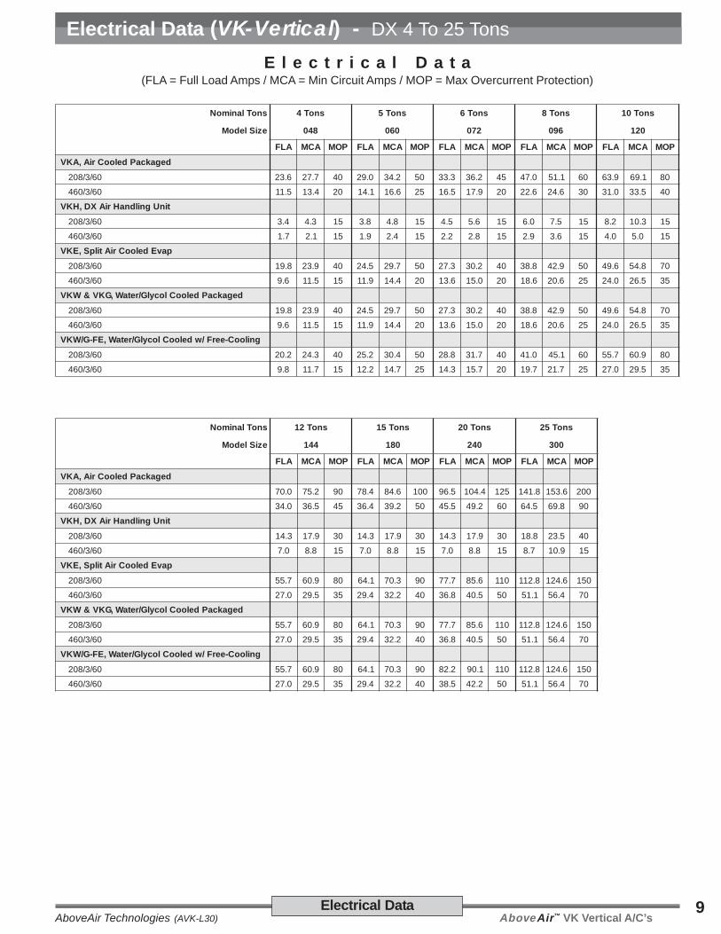
Electrical Data (VK-Vertical) - DX 4 To 25 Tons
snoTlanimoN snoT4 snoT5 snoT6 snoT8 snoT01
eziSledoM 840 060 270 690 021
ALF ACM POM ALF ACM POM ALF ACM POM ALF ACM POM ALF ACM POM
degakcaPdelooCriA,AKV
06/3/802 6.32 7.72 04 0.92 2.43 05 3.33 2.63 54 0.74 1.15 06 9.36 1.96 08
06/3/064 5.11 4.31 02 1.41 6.61 52 5.61 9.71 02 6.22 6.42 03 0.13 5.33 04
tinUgnildnaHriAXD,HKV
06/3/802 4.3 3.4 51 8.3 8.4 51 5.4 6.5 51 0.6 5.7 51 2.8 3.01 51
06/3/064 7.1 1.2 51 9.1 4.2 51 2.2 8.2 51 9.2 6.3 51 0.4 0.5 51
pavEdelooCriAtilpS,EKV
06/3/802 8.91 9.32 04 5.42 7.92 05 3.72 2.03 04 8.83 9.24 05 6.94 8.45 07
06/3/064 6.9 5.11 51 9.11 4.41 02 6.31 0.51 02 6.81 6.02 52 0.42 5.62 53
degakcaPdelooClocylG/retaW,GKV&WKV
06/3/802 8.91 9.32 04 5.42 7.92 05 3.72 2.03 04 8.83 9.24 05 6.94 8.45 07
06/3/064 6.9 5.11 51 9.11 4.41 02 6.31 0.51 02 6.81 6.02 52 0.42 5.62 53
gnilooC-eerF/wdelooClocylG/retaW,EF-G/WKV
06/3/802 2.02 3.42 04 2.52 4.03 05 8.82 7.13 04 0.14 1.54 06 7.55 9.06 08
06/3/064 8.9 7.11 51 2.21 7.41 52 3.41 7.51 02 7.91 7.12 52 0.72 5.92 53
E l e c t r i c a l D a t a(FLA = Full Load Amps / MCA = Min Circuit Amps / MOP = Max Overcurrent Protection)
snoTlanimoN snoT21 snoT51 snoT02 snoT52
eziSledoM 441 081 042 003
ALF ACM POM ALF ACM POM ALF ACM POM ALF ACM POM
degakcaPdelooCriA,AKV
06/3/802 0.07 2.57 09 4.87 6.48 001 5.69 4.401 521 8.141 6.351 002
06/3/064 0.43 5.63 54 4.63 2.93 05 5.54 2.94 06 5.46 8.96 09
tinUgnildnaHriAXD,HKV
06/3/802 3.41 9.71 03 3.41 9.71 03 3.41 9.71 03 8.81 5.32 04
06/3/064 0.7 8.8 51 0.7 8.8 51 0.7 8.8 51 7.8 9.01 51
pavEdelooCriAtilpS,EKV
06/3/802 7.55 9.06 08 1.46 3.07 09 7.77 6.58 011 8.211 6.421 051
06/3/064 0.72 5.92 53 4.92 2.23 04 8.63 5.04 05 1.15 4.65 07
degakcaPdelooClocylG/retaW,GKV&WKV
06/3/802 7.55 9.06 08 1.46 3.07 09 7.77 6.58 011 8.211 6.421 051
06/3/064 0.72 5.92 53 4.92 2.23 04 8.63 5.04 05 1.15 4.65 07
gnilooC-eerF/wdelooClocylG/retaW,EF-G/WKV
06/3/802 7.55 9.06 08 1.46 3.07 09 2.28 1.09 011 8.211 6.421 051
06/3/064 0.72 5.92 53 4.92 2.23 04 5.83 2.24 05 1.15 4.65 07

AboveAir™ VK Vertical A/C’s AboveAir Technologies (AVK-L30)10 Electrical Data
Centrifugal Blower - DX Split - Air Cooled, Remote Condensing Units(FLA = Full Load Amps / MCA = Min Circuit Amps / MOP = Max Overcurrent Protection) * see notes 1-3 below
)roodtuO(roodnI,lacitreV-UCVrewolBlagufirtneC
stinUgnisnednoCetomeRdelooCriA
)roodtuO(roodnI,latnoziroH-UCXrewolBlagufirtneC
stinUgnisnednoCetomeRdelooCriA
ylppuSrewoP 06/3/802 06/3/064 ylppuSrewoP 06/3/802 06/3/064
840-UCV 840-UCX
ALF 2.02 8.9 ALF 2.02 8.9
ACM 3.42 7.11 ACM 3.42 7.11
POM 04 51 POM 04 51
060-UCV 060-UCX
ALF 2.52 2.21 ALF 2.52 2.21
ACM 4.03 7.41 ACM 4.03 7.41
POM 05 02 POM 05 02
270-UCV 270-UCX
ALF 8.82 3.41 ALF 8.82 3.41
ACM 7.13 7.51 ACM 7.13 7.51
POM 04 02 POM 04 02
690-UCV 690-UCX
ALF 0.14 7.91 ALF 0.14 7.91
ACM 1.54 7.12 ACM 1.54 7.12
POM 06 52 POM 06 52
021-UCV 021-UCX
ALF 7.55 0.72 ALF 9.45 5.62
ACM 9.06 5.92 ACM 1.06 0.92
POM 08 53 POM 08 53
441-UCV 441-UCX
ALF 7.55 0.72 ALF 9.45 5.62
ACM 9.06 5.92 ACM 1.06 0.92
POM 08 53 POM 08 53
081-UCV 081-UCX
ALF 1.46 4.92 ALF 3.36 9.82
ACM 3.07 2.23 ACM 5.96 7.13
POM 09 04 POM 09 04
042-UCV
ALF 2.28 5.83
ACM 1.09 2.24
POM 011 05
003-UCV
ALF 0.321 8.55
ACM 8.431 1.16
POM 571 08
Electrical Data (VK-Vertical) - Remote Condensers / ing
AboveAir™ VK Vertical A/C’sAboveAir Technologies (AVK-L30)11Electrical Data / Ship Wts
Electrical Data (VK-Vertical) - DX 4 To 25 Tons
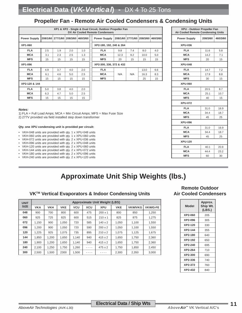
Propeller Fan - Remote Air Cooled Condensers & Condensing UnitsnaFrelleporProodtuO,tiucriClauD&elgniS-2PX&1PX
sresnednoCetomeRdelooCriAXDnaFrelleporProodtuO-UPX
stinUgnisnednoCetomeRdelooCriA
ylppuSrewoP 06/1/802 06/1/772 06/3/802 06/3/064 ylppuSrewoP 06/1/802 06/1/772 06/3/802 06/3/064 ylppuSrewoP 06/3/802 06/3/064
060-1PX 462&042,291,081-2PX 630-UPX
ALF 5.2 9.1 0.2 0.1 ALF 8.9 4.7 0.8 0.4 ALF 6.11 8.5
ACM 1.3 3.2 5.2 3.1 ACM 3.21 2.9 0.01 0.5 ACM 2.41 1.7
SFM 51 51 51 51 SFM 02 51 51 51 SFM 02 51
690-1PX 234&273,633,003-2PX 840-UPX
ALF 9.4 7.3 0.4 0.2 ALF
A/N A/N
0.31 6.6 ALF 7.41 2.7
ACM 1.6 6.4 0.5 5.2 ACM 3.61 3.8 ACM 9.71 8.8
SFM 51 51 51 51 SFM 52 51 SFM 03 51
441&021-2PX 060-UPX
ALF 0.5 8.3 0.4 0.2 ALF 5.02 7.8
ACM 3.6 7.4 0.5 5.2 ACM 1.52 7.01
SFM 51 51 51 51 SFM 04 51
270-UPX
ALF 0.13 9.61
ACM 4.43 7.81
SFM 54 52
690-UPX
ALF 0.13 9.61
ACM 4.43 7.81
SFM 54 52
021-UPX
ALF 1.04 9.02
ACM 4.44 2.32
SFM 06 03
Approximate Unit Ship Weights (lbs.)
Remote OutdoorAir Cooled CondensersVKTM Vertical Evaporators & Indoor Condensing Units
TINUEZIS
)SBL(thgieWtinUetamixorppA
AKV HKV EKV UCV UCX UPX EKV GKV/WKV EF-G/WKV
840 009 007 008 006 574 1x002 008 058 052,1
060 529 527 528 006 515 1x012 528 578 572,1
270 051,1 009 050,1 027 585 2x041 050,1 001,1 055,1
690 002,1 009 050,1 027 095 2x002 050,1 001,1 055,1
021 522,1 529 570,1 537 598 2x012 570,1 521,1 576,1
441 058,1 002,1 056,1 041,1 049 2x514 056,1 057,1 063,2
081 009,1 002,1 056,1 041,1 049 2x514 056,1 057,1 063,2
042 001,2 052,1 057,1 062,1 ---- 2x574 057,1 058,1 054,2
003 005,2 005,1 0032 005,1 ---- ---- 003,2 053,2 000,3
edoM l.xorppA.tWpihS
).SBL(
060-2PX 502
690-2PX 503
021-2PX 033
441-2PX 553
081-2PX 046
291-2PX 056
042-2PX 596
462-2PX 017
003-2PX 096
633-2PX 047
273-2PX 067
234-2PX 048
Qty. one XPU condensing unit is provided per circuit:
• VKH-048 units are provided with qty. 1 x XPU-048 units• VKH-060 units are provided with qty. 1 x XPU-060 units• VKH-072 units are provided with qty. 2 x XPU-036 units• VKH-096 units are provided with qty. 2 x XPU-048 units• VKH-120 units are provided with qty. 2 x XPU-060 units• VKH-144 units are provided with qty. 2 x XPU-072 units• VKH-180 units are provided with qty. 2 x XPU-096 units• VKH-240 units are provided with qty. 2 x XPU-120 units
Notes:1) FLA = Full Load Amps; MCA = Min Circuit Amps; MFS = Max Fuse Size2) 277V provided via field installed step down transformer

AboveAir™ VK Vertical A/C’s AboveAir Technologies (AVK-L30)12 Guide Specifications
1.0 General
1.1 Summary
These specifications describe therequirements for a comfort cooling verticalfloor mounted packaged (or split) airconditioner. The system shall be de-signed to control space temperature andhumidity.
The air conditioning manufacturer shalldesign and furnish all equipment in thequantities and configurations shown onthe project plans and specifications.
The system shall be provided by AboveAirTechnologies in Frederick, Maryland,USA. The system shall be listed byIntertek (ETL Semko), Inc. to conform withUL Std 1995 and be certified to CAN/CSAStd C22.2 No. 236 (Control No. 3091370).The system shall be NYC MEA229-06-Eand Chicago Code Approved. Thesystem model number shall be_____________.
1.2 Design Requirements
The system shall be an AboveAir Tech-nologies VK-Vertical™ brand factoryassembled and tested. The system shallbe designed for indoor installation.
The system shall have a total coolingcapacity of ______ BTU/H, and a sensiblecooling capacity of ______ BTU/H, basedon an entering air condition of ______ °FDB, and ______ °F WB, ______ % RH.
The evaporator section shall be designedfor _____ Volt, ______ Phase, _____Hertz main power supply. The remotecondensing unit section (if applicable)shall be designed for _____ Volt, ______Phase, _____ Hertz main power supply.
1.3 Submittals
Submittals shall be provided aftermanufacturer’s receipt of a writtenpurchase order and shall include:Detailed Performance and Electrical Data;Guide Specifications; and DimensionalDrawings.
1.4 Quality Assurance
The system shall be factory run testedprior to shipment. Testing shall include,but shall not be limited to: “HiPot” Test (2times rated voltage plus 1000 volts, perUL 1995 testing requirements). Thesystem shall be designed and manufac-tured according to world class qualitystandards.
2.0 Products
2.1 Standard Features /All Systems
2.1.1 Cabinet
The cabinet chassis and access panelsshall be powder-coat painted heavygauge galvanneal steel for decor match-ing and corrosion resistance. Cabinetaccess panels shall rest in recessedpockets designed for minimum airleakage. The cabinet and access panelsshall be lined with 2 lb/ft2 high densitysound and thermal insulation and sealedwith self-extinguishing gasketing conform-ing to NFPA 90A and 90B.
Splittable for Ease of Rigging:The cabinet shall be modular in design toallow for easy field break-down andreassembly of top evaporator and bottomcondensing unit sections for riggingpurposes. As a standard, the systemshall ship from the factory as a one pieceunit.
(Note: VKA-144 thru 300 system ship in twosections from the factory for field assemblyafter rigging.)
2.1.2 Component Access
The unit shall be serviceable through frontand side access panels with quick-release quarter-turn fasteners.
2.1.3 Electrical System
General:The electrical system shall conform toNational Electric Code (NEC) require-ments according to UL 1995. The controlcircuit shall be a 24 VAC low voltagecircuit.
The electrical system shall include, butnot be limited to the following factoryinstalled items: main power distributionblock; grounding lug; 24 VAC controltransformer; terminal connections; andmotor controllers with start protection andcircuit breakers for blower motors,compressors and each electric heaterstage (if applicable).
Overflow Safety Float Switches:The system shall be provided with afactory installed float type condensateoverflow safety switches. The circuit shallbe designed to shut down all systemwater producing operations in the event ofan overflow condition.
2.1.4 Air Distribution
The system air distribution shall beconfigured for a draw-through air patternto provide even air distribution andmaximum coil performance.
2.1.4.1 Blowers / Motors
The blower shall be the belt-drivencentrifugal type, double width doubleinlet (DWDI), and statically and dynami-cally balanced to a minimum vibrationlevel. The shaft shall be heavy dutysteel with self-aligning ball bearingssized for an average 100,000 hours ofservice life.
The blower motor shall be ____ Hp at1725 RPM (or 3450 RPM) and mountedon an adjustable base. Belts shall besized for 200% of the motor horsepowerrating. Motors shall have overloadprotection and a minimum NEMA servicefactor of 1.15.
Evaporator Blowers:The evaporator blower assembly shallbe designed for ____ CFM @ ____inches external static pressure (e.s.p.)
Condenser Blowers: (DX Air Cooled)The evaporator blower assembly shallbe designed for ____ CFM @ ____inches external static pressure (e.s.p.)
2.1.4.2 Air Patterns
Top Discharge Front Discharge (standard) (optional)
Top Evap Air Discharge: (standard)The evaporator shall be designed for free
Guide Specifications - VK Vertical A/C’s (4-25 Tons)

AboveAir™ VK Vertical A/C’sAboveAir Technologies (AVK-L30)13Guide Specifications
Guide Specifications - VK Vertical A/C’s (4-25 Tons)
or ducted rear-unit return air inlet and topducted air discharge. Air inlet and outletconnections shall include factory providedturned-out duct flanges for each of fieldduct connection.
Front Evap Air Discharge: (optional)The evaporator shall be designed for freeor ducted rear-unit return air inlet andfront ducted air discharge. Air inlet andoutlet connections shall include factoryprovided turned-out duct flanges for eachof field duct connection.
Packaged Air Cooled Condensers:
ACCESS
PANELCondenserAir Inlet
CondenserAir Outlet
The integral air cooled condenser shall bedesigned for rear-unit ducted same-faceair distribution. Air inlet and outletconnections shall include factory providedturned-out duct flanges for each of fieldduct connection.
2.1.4.3 Air Filtration
The filter(s) shall be 2 inch thick pleatedand rated for 30% dust spot efficiency(based on ASHRAE 52.1). The filter(s)shall be serviceable through a sideaccess without shutting down thesystem.
2.2 Direct Expansion Systems
2.2.1 DX - Evaporator Coils
The DX evaporator coil shall be con-structed of copper tubes and aluminumfins. The system shall be designed for adraw-through air pattern for maximumheat transfer. Coil end-plates shall be hotdipped galvanized. The evaporator coilshall be mounted in an insulated stainlesssteel condensate drain pan.
2.2.2 Scroll Compressors
Each compressor shall be the highefficiency, low sound Scroll type mountedon vibration isolators and located in aseparate compartment out of the evapora-tor air stream to facilitate servicing whileequipment is operating. Each compres-sor shall be complete with reversiblepositive oil pump, charging and serviceports, internal spring isolation, anddischarge gas vibration eliminator.
2.2.3 DX - Refrigeration Circuits
Each refrigeration circuit shall be pre-piped with type “L” refrigerant coppertubing. The refrigeration system shallinclude but not be limited to: expansionvalve with external equalizer and rapidbleed-through capacity. Features shallinclude filter dryer, sight glass, pressurefittings and high pressure/low pressuresafety cutouts.
2.3 Standard Features /Individual Systems
2.3.1 DX - Air Cooled Systems
2.3.1.1 DX - Air Cooled(Self-Contained Systems)Models: VKA-( )
The system shall be a self-contained,vertical floor mounted air conditioner withfactory mounted integral dx air cooledcondensing unit with belt-driven centrifu-gal blower. The condensing unit shall besized for full heat of rejection at 95°Fambient and be capable of operation to___ °F low ambient air temperature
The system shall require only single pointmain power supply and ship from thefactory with a full operating refrigerantcharge.
(Note-1: Low Ambient Control is Optional -see options for more detail.)
2.3.1.2 DX - Air Handling Unit(Split, DX Air Handling Unit)Models: VKH-( )
The system shall be a split indoor verticalfloor mounted dx air handling unitdesigned for field connection to thespecified remote condensing unit (air,water or glycol cooled). The air handlingunit shall include, but not be limited to:evaporator coil; centrifugal belt-drivenblower and blower motor; thermalexpansion valve with rapid bleed port,shraeder service valves; main powerdistribution block; grounding lug; 24 Vaccontrol transformer; individual blowermotor contactors; and terminal strip.
The air handling unit shall ship from thefactory with a dry-nitrogen holding chargefor field sweat (copper) connection andrefrigerant charging.
2.3.1.3 DX - Air Cooled RemoteCondensing Unit(Indoor/Outdoor CentrifugalBlower Configuration)
CondenserAir Outlet Condenser
Air Inlet
ACCESS
PANEL ACCESS
PANELCondenserAir Inlet
CondenserAir Outlet
XCU - Horizontal XVU - Vertical
The system shall be an indoor horizontalceiling mounted (opt. outdoor horizontal)or vertical floor mounted remote aircooled belt-driven centrifugal blowercondensing unit. The remote condensingunit shall include, but not be limited to:condenser coil; centrifugal belt-drivenblower and blower motor; compressor;sight glass; shraeder service valves; high& low refrigerant pressure switches; mainpower distribution block; grounding lug;24 Vac control transformer; individualblower motor and compressor starters/contactors; and terminal strip.
The condensing unit shall be sized for fullheat of rejection at 95°F ambient and becapable of operation to ___ °F lowambient air temperature.
The condensing unit shall ship from thefactory with a dry-nitrogen holding chargefor field sweat (copper) connection.

AboveAir™ VK Vertical A/C’s AboveAir Technologies (AVK-L30)14 Guide Specifications
2.3.1.4 DX - Air Cooled(Split Evaporator Systems)Models: VKE-( )
The system shall be a split dx, verticalfloor mounted evaporator section forconnection to a remote air cooledcondenser. The compressor(s) shall belocated in the evaporator section. Theevaporator shall included, but not belimited to: evaporator coil; centrifugal belt-driven blower and blower motor; thermalexpansion valve with rapid bleed port,shraeder service valves; compressor(s),refrigerant filter-drier and sight-glass;main power distribution block; groundinglug; 24 Vac control transformer; individualblower motor contactors; and terminalstrip.
The system shall require only single pointmain power supply and ship from thefactory with a dry-nitrogen holding chargefor field sweat (copper) connection andrefrigerant charging.
2.3.1.5 DX - Air Cooled RemoteCondensing Unit(Outdoor Propeller Fan)XP_-( )
The system shall be an outdoor mountedremote air cooled direct-driven propellerfan(s) condenser. The remote condens-ing unit shall include, but not be limited to:condenser coil; direct drive propellerfan(s) and fan motor(s); close-meshedsteel wire with vinyl coating fan guards;shraeder service valves; main powerdistribution block; grounding lug; dry-contact interlock for evaporator 24 Vaccontrol signal; fan motor starters/contactors; and terminal strip.
The condenser shall be sized for full heatof rejection at 95°F ambient and becapable of operation to ___ °F lowambient air temperature.
The condenser shall ship from the factorywith a dry-nitrogen holding charge for fieldsweat (copper) connection.
(Note-1: Select 0°F Fan Cycling or -20°FVariable Speed Fan Low Ambient head
pressure control as application requires - seeoptions for more detail.)
2.3.2 DX - Water Cooled Systems
2.3.2.1 DX - Water Cooled(Self-Contained Systems)Models: VKW-( )
The system shall be a self-contained,vertical floor mounted air conditioner withintegral dx water cooled condensing unit.The system shall include a water cooledtube-in-tube coaxial condenser andfactory installed head pressure controlling2-way water regulating valve rated for 150psi w.w.p. The water cooled condensershall be designed to provide the totalrequired system heat of rejection at 85°Fentering water temperature and 95°Fleaving water temperature. Source watershall be provided by a remote watersource (by others).
The system shall require only single pointmain power supply and ship from thefactory with a full operating refrigerantcharge.
(Note: Higher pressure and 3-way valves areoptionally available, see option 2.4.2.)
2.3.3 DX - Glycol Cooled Systems
2.3.3.1 DX - Glycol Cooled(Self-Contained Systems)Models: VKG-( )
The system shall be a self-contained,vertical floor mounted air conditioner withintegral dx glycol cooled condensing unit.The system shall include a glycol cooledtube-in-tube coaxial condenser andfactory installed head pressure controlling2-way glycol regulating valve rated for150 psi w.w.p. The condenser shall bedesigned to provide the total requiredsystem heat of rejection at 110°F enteringglycol temperature and 120°F leavingglycol temperature based on 40%ethylene glycol solution. Source glycol
shall be provided by a remote glycoldrycooler source (see AboveAir Technolo-gies’ FluidCool™ drycoolers).
The system shall require only single pointmain power supply and ship from thefactory with a full operating refrigerantcharge.
(Note: Higher pressure and 3-way valves areoptionally available, see option 2.4.2.)
2.3.3.2 Glycol Pump Packages& DrycoolersFC_-( ) / PA-( )
Glycol condenser source shall beprovided by a FluidCool™ brand remoteair cooled glycol drycooler and Pump-All™ brand pump package.
The glycol drycooler shall be the outdoormounted propeller fan type complete withfactory installed aquastat fan cyclingcontrols, motor starters with overloadprotection and non-fused disconnectswitch.
The glycol pump package shall be a(single or dual) pump package designedfor outdoor installation complete withindividual pump motor starters. Dualglycol pump packages shall be providedwith manual lead-lag switch and fieldinstalled flow switch for automaticswitchover to backup pump upon loss offlow.
An expansion tank and AirTrol air bleedfitting shall be factory provided for fieldinstallation.
The drycooler shall provide __________BTUH total heat rejection at a flow rate of_____ GPM with ____ °F EGT and ____°F LGT at ____ °F ambient air tempera-ture. Each pump shall be ____ Hp andshall be sized to provide ____ GPM @____ Ft. w.g. total system head. Theglycol solution shall be ___ % (ethyleneor propylene) by volume.
The drycooler and pump package shall bedesigned for _____ Volt, ______ Phase,_____ Hertz main power supply.
(Note: See AboveAir Technologies’ Fluid-Cool™ indoor & outdoor glycol drycooler andPumpAll™ glycol pump packages engineeringmanuals for more information.)
Guide Specifications - VK Vertical A/C’s (4-25 Tons)

AboveAir™ VK Vertical A/C’sAboveAir Technologies (AVK-L30)15Guide Specifications
2.4 Options
2.4.1 Air Cooled Condenser -Low Ambient Control
2.4.1.1 -20°F Ambient -Variable Speed Fan(XCU, XP1/2 & XPU)
Variable fan speed head pressurecontrols (JCI P266 DD or BD VFD66 /VFD) shall be factory installed toallow for low ambient operation to-20°F. Compressor cold start timedelay relay and crankcase heatershall be factory installed with the -20°F low ambient control feature.
2.4.1.2 30°F FloodedCondenser(All Condnser Models)
A flooded condenser system shallbe provided to allow for lowambient condenser operation to -30°F. The flooded system shallinclude a factory installed liquidrefrigerant receiver and modulat-ing head pressure control valve.Compressor cold start time delayrelay and crankcase heater shallbe factory installed with the -30°Flow ambient control feature.
2.4.2 DX - Water/GlycolCooled Reg. Valves
2.4.2.1 2-Way, 150 psig Reg. Valve
2.4.2.2 3-Way, 150 psig Reg. Valve
2.4.2.3 2-Way, 350 psig Reg. Valve
2.4.2.4 3-Way, 350 psig Reg. Valve
System head pressure shall be con-trolled by a factory provided ____ -waywater / glycol regulating valve rated for____ psig w.w.p.
2.4.2 CONTROL OPTIONS
2.4.2.1 DT-201, 202 & 203™ -Digital H/C Thermostat(7-day programmable)
A remote wall mounted deluxe 7-dayprogrammable heat pump ready thermo-stat with digital display shall be factoryprovided for field installation. Thethermostat shall include FAN AUTO-ON,COOL-OFF-HEAT-EM (emergency heat),SET and PROG/MAN selector switches.
(Note: 201 = 1-Stg H/C; 202 = 2-Stg H/C; 203= 3-Stg H/2-Stg C.)
2.4.2.2 MC-2000™, AdvancedMicroprocessor T/HController w/ Alarms
The system shall be provided with a MC-2000™ advanced microprocessor basedtemperature and humidity controller withalarms.
Select Features/Benefits:• 4x20 Character Liquid Crystal
Alpha-numerical Display• User Configurable• Run-Time Hours• Current Unit Mode Status• Alarm Status• Digital & Analog Inputs / Outputs• Temperature Anticipation• Remote Stop / Start Contact• Summary Alarm Contact• Automatic or Manual (selectable)
Restart After Power Loss• Sequential Load After Restart• Recovery Delay• Compressor Short Cycle Timers• Cold Start Time Delay• Security Password Access• Self-Diagnostics• Service Mode
Unit Status DisplayThe control system shall display currentunit functions and room status (ifapplicable):
• Current Dry Bulb Temp Set Point• Current Relative Humidity Set Point• System ON/OFF
• Cooling• Heating• Humidifying• Dehumidifying• Reheating• Actual Room DB Temperature• Actual Room Relative Humidity
Alarm Conditions:Alarm conditions activate an audible andvisual indicator plus close a summaryalarm dry contact connection. The controlsystem shall alert to the following alarmconditions (if applicable):
• High Temperature • High Head Press• Low Temperature • Smoke Detection• High Humidity • Firestat• Low Humidity • Leak Detection• Sensor Failure • Sensor Failure• Summary Failure • Loss of Power
• Loss of Air Flow• Dirty Filter
Digital & Analog Control Inputs /Outputs:The control system shall be capable ofboth digital (ON/OFF) and analog(proportional integral, PI) input and outputcontrol.
Select MC-2000 Options: Multi-Unit N+1 Sequencing
BMS Communications Interface:
ModBus RS485 Serial Connection BACnet over MS/TP (RS485 Serial) BACnet Over IP (Ethernet / EIA485) LonWorks FTT10 (RS485 Serial)
2.4.3 HEAT OPTIONS
2.4.3.1 Electric Duct Heater
An electric duct mounted heater shall befactory provided for field installation. Theduct heater shall be the open wirenichrome element type complete withindividual heater stage starter/contactor,air flow switch and overheat safeties. Theduct heater shall require a separate mainpower supply from the unit. The electricheat shall have a capacity of ________BTU/HR and a KW rating of ___ KW,controlled in ___ stages.
Guide Specifications - VK Vertical A/C’s (4-25 Tons)

AboveAir™ VK Vertical A/C’s AboveAir Technologies (AVK-L30)16 Guide Specifications
2.4.3.1.2 SCR Fired ElectricDuct Heater
The electric heat shall be controlledthrough a “zero firing” silicon controlrectifier (SCR) with an extruded alumi-num heat sink and solid state logicsystem to provide close dry bulb tem-perature control of the leaving condi-tioned air temperature. The electric heatshall have a capacity of _________ BTU/HR and a KW rating of ___ KW.
2.4.3.2 Steam Heat
A Steam Heat system shall be providedcomplete with a factory installed alumi-num fin, copper tube steam coil and fieldinstalled 2-way motorized steam controlvalve. Steam piping specialties shall befield provided. Steam shall be providedby a remote source at the specifiedtemperature and pressure. The steamheat system shall have a rated capacityof _________ BTU/HR @ ____ psigsaturated steam.
2.4.3.3 Hot Water Heat
A Hot Water Heat system shall beprovided complete with a factory installedaluminum fin, copper tube hot water coiland field installed 2-way motorized steamcontrol valve. Hot water shall beprovided by a remote source at thespecified flow rate and temperature. Thehot water heat system shall have a ratedcapacity of _________ BTU/H @ ______GPM, _____°F EWT.
2.4.3.4 Heat Pump Option
The system shall include a factoryinstalled heat pump heating cycleincluding reversing valve and auto-matic defrost cycle (if appl.). Theheat pump mode heating capacityshall be _______ BTU/HR.
2.5 Accessories
2.5.1 Condensate Pump
A condensate pump shall be factoryprovided for field installation. Thecondensate pump shall be providedwith dual internal float switches: one forpump operation initiation and the otherfor pump reservoir overflow safety. Thepump shall be powered through an A/Cunit main power fused terminal connec-tion.
2.5.2 Hot Gas Bypass Systems
2.5.2.1 Hot Gas Bypass ToEvaporator Inlet
Each refrigerant circuit shall be providedwith a factory installed hot gas (dis-charge) bypass valve. The hot gasbypass valve shall be designed to supplyhot gas to evaporator inlet as required toprovide coil freeze-protection andcapacity modulation under low loadconditions.
(Note: 3rd Line - Each circuit of a Split DXsystem with compressor located in condens-ing unit shall require a field installed copperhot gas bypass refrigerant line between theevaporator and condensing unit sections.)
2.5.2.2 Hot Gas Bypass ToSuction Line withQuench Valve(3rd Line Not Required!)
Each refrigerant circuit of the Split DXsystem shall be provided with a factoryinstalled hot gas bypass system toinclude: hot gas (discharge) bypass;desuperheating quench; and hot gas &quench solenoid valves. The hot gasbypass system shall be designed tosupply hot gas and liquid refrigerant tothe suction line as required to providecoil freeze-protection and capacitymodulation under low load conditions.All hot gas bypass components shall befactory installed and shall not requireadditional field refrigerant lines on splitDX systems.
2.5.3 Suction-Line Accumulators
Each refrigerant circuit shall be providedwith a factory installed Suction-LineAccumulator to prevent liquid slugging ofthe compressor and excessive refriger-ant dilution of the compressor oil duringlow load conditions. The accumulatorshall return refrigerant and oil to thecompressor at a sufficient rate tomaintain both system operating effi-ciency and proper oil level. The accumu-lators shall be wrapped with a 1/2”closed-cell neoprene insulation toprevent sweating.
2.5.4 Main Power, Non-FusedDisconnect
A main power non-fused disconnectshall be factory provided for field installa-tion. The disconnect shall be NEMArated for indoor or outdoor installation asrequired.
2.5.5 Firestat
A Firestat shall be factory provided forfield installation in the return air duct andwired to the A/C unit electrical controlpanel. The Firestat shall shut-down all A/C system operations upon sensing ahigh return air temperature condition.
2.5.6 Smoke Detector
A Smoke Detector shall be factoryprovided for field installation in the returnair duct and wired to the A/C unit electricalcontrol panel. The Smoke Detector shall
Guide Specifications - VK Vertical A/C’s (4-25 Tons)
AboveAir™ VK Vertical A/C’sAboveAir Technologies (AVK-L30)17Guide Specifications
shut-down all A/C system operationsupon activation.
2.5.7 Remote Water Detector
A remote water-leak detector shall befactory provided for field installation. Theremote water-leak detector shall be wiredto shut down all A/C unit water producingfunctions upon sensing a water leak.
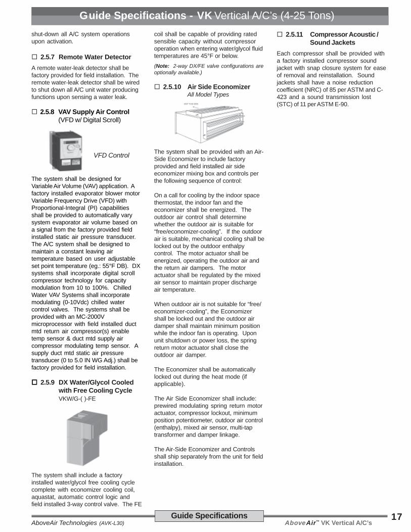
2.5.8 VAV Supply Air Control(VFD w/ Digital Scroll)
VFD Control
The system shall be designed forVariable Air Volume (VAV) application. Afactory installed evaporator blower motorVariable Frequency Drive (VFD) withProportional-Integral (PI) capabilitiesshall be provided to automatically varysystem evaporator air volume based ona signal from the factory provided fieldinstalled static air pressure transducer.The A/C system shall be designed tomaintain a constant leaving airtemperature based on user adjustableset point temperature (eg.: 55°F DB). DXsystems shall incorporate digital scrollcompressor technology for capacitymodulation from 10 to 100%. ChilledWater VAV Systems shall incorporatemodulating (0-10Vdc) chilled watercontrol valves. The systems shall beprovided with an MC-2000Vmicroprocessor with field installed ductmtd return air compressor(s) enabletemp sensor & duct mtd supply aircompressor modulating temp sensor. Asupply duct mtd static air pressuretransducer (0 to 5.0 IN WG Adj.) shall befactory provided for field installation.
2.5.9 DX Water/Glycol Cooledwith Free Cooling CycleVKW/G-( )-FE
The system shall include a factoryinstalled water/glycol free cooling cyclecomplete with economizer cooling coil,aquastat, automatic control logic andfield installed 3-way control valve. The FE
coil shall be capable of providing ratedsensible capacity without compressoroperation when entering water/glycol fluidtemperatures are 45°F or below.
(Note: 2-way DX/FE valve configurations areoptionally available.)
2.5.10 Air Side EconomizerAll Model Types
The system shall be provided with an Air-Side Economizer to include factoryprovided and field installed air sideeconomizer mixing box and controls perthe following sequence of control:
On a call for cooling by the indoor spacethermostat, the indoor fan and theeconomizer shall be energized. Theoutdoor air control shall determinewhether the outdoor air is suitable for“free/economizer-cooling”. If the outdoorair is suitable, mechanical cooling shall belocked out by the outdoor enthalpycontrol. The motor actuator shall beenergized, operating the outdoor air andthe return air dampers. The motoractuator shall be regulated by the mixedair sensor to maintain proper dischargeair temperature.
When outdoor air is not suitable for “free/economizer-cooling”, the Economizershall be locked out and the outdoor airdamper shall maintain minimum positionwhile the indoor fan is operating. Uponunit shutdown or power loss, the springreturn motor actuator shall close theoutdoor air damper.
The Economizer shall be automaticallylocked out during the heat mode (ifapplicable).
The Air Side Economizer shall include:prewired modulating spring return motoractuator, compressor lockout, minimumposition potentiometer, outdoor air control(enthalpy), mixed air sensor, multi-taptransformer and damper linkage.
The Air-Side Economizer and Controlsshall ship separately from the unit for fieldinstallation.
2.5.11 Compressor Acoustic /Sound Jackets
Each compressor shall be provided witha factory installed compressor soundjacket with snap closure system for easeof removal and reinstallation. Soundjackets shall have a noise reductioncoefficient (NRC) of 85 per ASTM and C-423 and a sound transmission lost(STC) of 11 per ASTM E-90.
Guide Specifications - VK Vertical A/C’s (4-25 Tons)

AboveAir™ VK Vertical A/C’s AboveAir Technologies (AVK-L30)18
DX - Air Cooled, Self-Contained - Top Evap DischargeModels: VKA-048, 060 & 072 (Single Compressor)
DX - Air Cooled, Self-Contained - Front Evap DischargeModels: VKA-048, 060 & 072 (Single Compressor)
Dimensional Data
4.34"
24.9"
1.69"
29.23"
14.07"
31.5"
1.18"
4.06"
32.13"(1.0" Duct Flange)
1.94"
ACCESS
PANEL
ACCESS
PANEL
EvaporatorAir Inlet
CondenserAir Outlet
CondenserAir Inlet
EvaporatorAir Outlet
32.0"
79.0"
48.0"
31.0"
36.0"
ACCESSPANEL(Electric Box)
ACCESS
PANEL
ACCESS
PANEL
EvaporatorAir Inlet
Evap CondensateDrain (3/4" FPT)
Cond CondensateDrain (3/4" FPT) -Optional
ACCESSPANEL
16.0"10.0"
16.0"
0.47"
EvaporatorAir Outlet
32.0"
4.34"
24.9"
1.69"
79.0"
48.0"
31.0"
36.0"
16.0"
10.0"
16.0"
0.38"
29.23"
14.07"
31.5"
1.18"
4.06"
32.13"(1.0" Duct Flange)
1.94"
ACCESSPANEL(Electric Box)
ACCESS
PANEL
ACCESS
PANEL
ACCESS
PANEL
ACCESS
PANEL
EvaporatorAir Inlet
EvaporatorAir Inlet
CondenserAir Outlet
CondenserAir Inlet
EvaporatorAir Outlet
EvaporatorAir Outlet
Evap CondensateDrain (3/4" FPT)
Cond CondensateDrain (3/4" FPT) -Optional
Dimensional Data - DX Air Cooled, Vertical SCAV (4-6 Tons)
AboveAir™ VK Vertical A/C’sAboveAir Technologies (AVK-L30)19
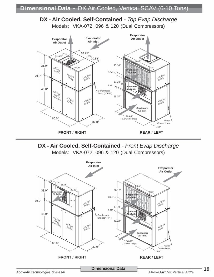
DX - Air Cooled, Self-Contained - Top Evap DischargeModels: VKA-072, 096 & 120 (Dual Compressors)
DX - Air Cooled, Self-Contained - Front Evap DischargeModels: VKA-072, 096 & 120 (Dual Compressors)
Dimensional Data
0.25"
1.69"
18.25"
20.88"18.25"
0.19"
3.34"
1.18"
32.0"60.0"
79.0"
48.0"
31.0"
EvaporatorAir Outlet
EvaporatorAir Inlet
ACCESSPANELACCESSPANEL
ACCESSPANEL(Electric Box)ACCESSPANEL
ACCESS
PANEL
ACCESS
PANEL
26.07"
17.38"
30.16"
56.63"(1.0" Duct Flange)
UtilityConnections
59.5"
FRONT / RIGHT REAR / LEFT
EvaporatorAir Outlet
EvaporatorAir Inlet
CondenserAir Outlet
CondenserAir Inlet
CondensateDrain (1" FPT)
ACCESS
PANEL
ACCESS
PANEL
ACCESSPANEL(Electric Box)ACCESSPANEL
ACCESS
PANEL
ACCESS
PANEL
ACCESS
PANEL
ACCESS
PANEL
32.0"60.0"
79.0"
48.0"
31.0"
EvaporatorAir Inlet
26.07"
17.38"
30.16"
56.63"(1.0" Duct Flange)
59.5"
FRONT / RIGHT REAR / LEFT
EvaporatorAir Inlet
CondenserAir Outlet
CondenserAir Inlet
EvaporatorAir Outlet
UtilityConnections
18.75"
20.88"
18.25"
1.25"
0.25"
1.69"
EvaporatorAir Outlet
CondensateDrain (1" FPT)
3.34"
1.18"
Dimensional Data - DX Air Cooled, Vertical SCAV (6-10 Tons)
AboveAir™ VK Vertical A/C’s AboveAir Technologies (AVK-L30)20
BLANK PAGE
Dimensional Data
Dimensional Data - DX Air Cooled, Vertical SCAV (12-15 Tons)
AboveAir™ VK Vertical A/C’sAboveAir Technologies (AVK-L30)21
DX - Air Cooled, Self-Contained - Top Evap Discharge
Models: VKA-144, 180 & 240 (Dual Compressors)
DX - Air Cooled, Self-Contained - Front Evap Discharge
Models: VKA-144, 180 & 240 (Dual Compressors)
Dimensional Data
19.0"
21.25"
12.38"21.25"
17.56"
78.63"(1.0" Duct Flange)
32.07"
15.38"
30.28"79.75"
ACCESSPANELACCESSPANEL
ACCESS
PANEL
ACCESSPANEL(Electric Box)ACCESSPANEL
ACCESS
PANEL
ACCESSPANEL
ACCESS
PANEL
ACCESS
PANEL
FRONT / RIGHT REAR / LEFT
CondenserAir Inlet
CondenserAir Outlet
EvaporatorAir Inlet
EvaporatorAir Outlet
EvaporatorAir Inlet
EvaporatorAir Outlet
UtilityConnections34.0"
82.0"
86.0"
52.0"
34.0"
0.19"
1.69"
ACCESSPANEL
CondensateDrain (1" FPT)
1.19"
3.34"
78.63"(1.0" Duct Flange)
32.07"
15.38"
30.28"79.75"
ACCESS
PANEL
ACCESS
PANEL
REAR / LEFT
CondenserAir Inlet
CondenserAir Outlet
EvaporatorAir Inlet
UtilityConnections
0.19"
1.69"
ACCESS
PANEL
ACCESSPANEL(Electric Box)ACCESSPANEL
ACCESS
PANEL
ACCESSPANEL
FRONT / RIGHT
EvaporatorAir Inlet
34.0"
82.0"
86.0"
52.0"
34.0"
EvaporatorAir Outlet
19.0"
21.25"
21.25"
12.38"
9.56"
1.44"
EvaporatorAir Outlet
CondensateDrain (1" FPT)
1.19"
3.34"
Dimensional Data - DX Air Cooled, Vertical SCAV (12-20 Tons)
AboveAir™ VK Vertical A/C’s AboveAir Technologies (AVK-L30)22
DX - Air Cooled, Self-Contained - Top Evap Discharge(Ships Split w/ Dry-Nitrogen Holding Charge For Rigging Purposes!)
Models: VKA-300 (Dual Compressors)
DX - Air Cooled, Self-Contained - Front Evap Discharge(Ships Split w/ Dry-Nitrogen Holding Charge For Rigging Purposes!)
Models: VKA-300 (Dual Compressors)
Dimensional Data
19.0"
21.25"
9.38"21.25"
21.56"
84.63"(1.0" Duct Flange)
41.75"
17.8"
40.1"82.0"
ACCESSPANELACCESSPANEL
ACCESS
PANEL
ACCESSPANEL(Electric Box)ACCESSPANEL
ACCESS
PANEL
ACCESSPANEL
ACCESS
PANEL
ACCESS
PANEL
FRONT / RIGHT REAR / LEFT
CondenserAir Inlet
CondenserAir Outlet
EvaporatorAir Inlet
EvaporatorAir Outlet
EvaporatorAir Inlet
EvaporatorAir Outlet
UtilityConnections34.0"
88.0"
104.0"
64.0"
40.0"
3.0"
1.69"
ACCESSPANEL
CondensateDrain (1" FPT)
1.18"
2.28"
84.63"(1.0" Duct Flange)
41.75"
17.8"
40.1"82.0"
ACCESS
PANEL
ACCESS
PANEL
REAR / LEFT
CondenserAir Inlet
CondenserAir Outlet
EvaporatorAir Inlet
UtilityConnections
3.0"
1.69"
ACCESS
PANEL
ACCESSPANEL(Electric Box)ACCESSPANEL
ACCESS
PANEL
ACCESSPANEL
FRONT / RIGHT
EvaporatorAir Inlet
34.0"
88.0"
104.0"
64.0"
40.0"
EvaporatorAir Outlet
19.0"
21.25"
21.25"
9.38"
14.56"
1.44"
EvaporatorAir Outlet
CondensateDrain (1" FPT)
1.18"
2.28"
Dimensional Data - DX Air Cooled, Vertical SCAV (25 Tons)
AboveAir™ VK Vertical A/C’sAboveAir Technologies (AVK-L30)23
16.0"
10.0"16.0"
0.47"
32.0"
EvaporatorAir Outlet
EvaporatorAir Inlet
ACCESSPANEL
ACCESSPANEL
ACCESS
PANEL
ACCESS
PANEL
4.34"
24.9"
UtilityConnections
1.69"
31.5"
FRONT / RIGHT REAR / LEFT
EvaporatorAir Outlet
EvaporatorAir Inlet62.0"
31.0"
31.0"
36.0"
CondensateDrain (3/4" FPT)
Water/Glycol Condenser,or DX Refrigerant Connections
ACCESS
PANEL
ACCESS
PANEL
DX - Water/Glycol Cooled & Split Air Cooled Evaps - Top Evap DischargeModels: VKW, VKG, VKE & VKH-048, 060 & 072 (Single Compressor)
DX - Water/Glycol Cooled & Split Air Cooled Evaps - Front Evap DischargeModels: VKW, VKG, VKE & VKH-048, 060 & 072 (Single Compressor)
Dimensional Data
32.0"
EvaporatorAir Inlet
4.34"
24.9"
FRONT / RIGHT REAR / LEFT
EvaporatorAir Inlet
62.0"
31.0"
31.0"
36.0"
1.69"
31.5"
UtilityConnections
CondensateDrain (3/4" FPT)
Water/Glycol Condenser,or DX Refrigerant Connections
16.0"
10.0"
16.0"
0.38"
EvaporatorAir Outlet
EvaporatorAir Outlet
ACCESSPANEL ACCESS
PANEL
ACCESS
PANEL
ACCESS
PANEL
ACCESS
PANEL
Dimensional Data - Vertical, DX Water/Glycol & Split Air Cooled (4-6T)
AboveAir™ VK Vertical A/C’s AboveAir Technologies (AVK-L30)24
0.25"
18.25"
20.88"18.25"
0.19"
32.0"60.0"
79.0"
48.0"
31.0"
EvaporatorAir Outlet
EvaporatorAir Inlet
ACCESSPANELACCESSPANEL
ACCESSPANEL(Electric Box)ACCESSPANEL
ACCESS
PANEL
ACCESS
PANEL
30.16"
UtilityConnections
59.5"
FRONT / RIGHT REAR / LEFT
EvaporatorAir Outlet
EvaporatorAir Inlet
CondensateDrain (1" FPT)
Water/Glycol Condenser,or DX Refrigerant Connections
ACCESS
PANEL
ACCESS
PANEL
0.25"
32.0"60.0"
79.0"
48.0"
31.0" EvaporatorAir Outlet
EvaporatorAir Inlet
ACCESSPANEL(Electric Box)ACCESSPANEL
ACCESS
PANEL
ACCESS
PANEL
30.16"
UtilityConnections
59.5"
FRONT / RIGHT REAR / LEFT
EvaporatorAir Outlet
EvaporatorAir Inlet
CondensateDrain (1" FPT)
Water/Glycol Condenser,or DX Refrigerant Connections
ACCESS
PANEL
ACCESS
PANEL
20.88"
18.25"1.25"
18.25"
DX - Water/Glycol Cooled & Split Air Cooled Evaps - Top Evap DischargeModels: VKW, VKG, VKE & VKH-072, 096 & 120 (Dual Compressors)
DX - Water/Glycol Cooled & Split Air Cooled Evaps - Front Evap DischargeModels: VKW, VKG, VKE & VKH-072, 096 & 120 (Dual Compressors)
Dimensional Data
Dimensional Data - Vertical, DX Water/Glycol & Split Air Cooled (6-10T)

AboveAir™ VK Vertical A/C’sAboveAir Technologies (AVK-L30)25
DX - Water/Glycol Cooled & Split Air Cooled Evaps - Top Evap DischargeModels: VKW, VKG, VKE & VKH-144, 180 & 240 (Dual Compressors)
DX - Water/Glycol Cooled & Split Air Cooled Evaps - Front Evap DischargeModels: VKW, VKG, VKE & VKH-144, 180 & 240 (Dual Compressors)
Dimensional Data
19.0"
21.25"
12.38"21.25"
17.56"30.28"79.75"
ACCESSPANELACCESSPANEL
ACCESS
PANEL
ACCESSPANEL(Electric Box)ACCESSPANEL
ACCESS
PANEL
ACCESSPANEL
ACCESS
PANEL
ACCESS
PANEL
FRONT / RIGHT REAR / LEFT
EvaporatorAir Inlet
EvaporatorAir Outlet
EvaporatorAir Inlet
EvaporatorAir Outlet
UtilityConnections34.0"
82.0"
74.0"
40.0"
34.0"
0.19"
ACCESSPANEL
CondensateDrain (1" FPT)
Water/Glycol Condenser,or DX Refrigerant Connections
30.28"79.75"
ACCESS
PANEL
ACCESS
PANEL
REAR / LEFT
EvaporatorAir Inlet
UtilityConnections
0.19"
ACCESS
PANEL
ACCESSPANEL(Electric Box)ACCESSPANEL
ACCESS
PANEL
ACCESSPANEL
FRONT / RIGHT
EvaporatorAir Inlet
34.0"
82.0"
74.0"
40.0"
34.0"
EvaporatorAir Outlet
19.0"
21.25"
21.25"
12.38"
9.56"
1.44"
EvaporatorAir Outlet
CondensateDrain (1" FPT)
Water/Glycol Condenser,or DX Refrigerant Connections
Dimensional Data - Vertical, DX Water/Glycol & Split Air Cooled (12-20T)

AboveAir™ VK Vertical A/C’s AboveAir Technologies (AVK-L30)26
DX - Water/Glycol Cooled & Split Air Cooled Evaps - Top Evap DischargeModel: VKW, VKG, VKE & VKH-300 (Dual Compressors/Circuits)
DX - Water/Glycol Cooled & Split Air Cooled Evaps - Front Evap DischargeModel: VKW, VKG, VKE & VKH-300 (Dual Compressors/Circuits)
40.1"82.0"
ACCESS
PANEL
ACCESS
PANEL
REAR / LEFT
EvaporatorAir Inlet
UtilityConnections
3.0"
ACCESS
PANEL
ACCESSPANEL(Electric Box)ACCESSPANEL
ACCESS
PANEL
ACCESSPANEL
FRONT / RIGHT
EvaporatorAir Inlet
34.0"
88.0"
80.0"
40.0"
40.0"
EvaporatorAir Outlet
19.0"
21.25"
21.25"
9.38"
14.56"
1.44"
EvaporatorAir Outlet
CondensateDrain (1" FPT)
Water/Glycol Condenser,or DX Refrigerant Connections
19.0"
21.25"
9.38"21.25"
21.56"40.1"82.0"
ACCESSPANELACCESSPANEL
ACCESS
PANEL
ACCESSPANEL(Electric Box)ACCESSPANEL
ACCESS
PANEL
ACCESSPANEL
ACCESS
PANEL
ACCESS
PANEL
FRONT / RIGHT REAR / LEFT
EvaporatorAir Inlet
EvaporatorAir Outlet
EvaporatorAir Inlet
EvaporatorAir Outlet
UtilityConnections34.0"
88.0"
80.0"
40.0"
40.0"
3.0"
ACCESSPANEL
CondensateDrain (1" FPT)
Water/Glycol Condenser,or DX Refrigerant Connections
Dimensional Data
Dimensional Data - Vertical, DX Water/Glycol Cooled & Split Evaps (25 Tons)

AboveAir™ VK Vertical A/C’sAboveAir Technologies (AVK-L30)27
“FE” - Free-Cooling Water/Glycol Economizer Box - 4 to 25 TonsModels: VKW/VKG-048 thru 300-FE
Dimensional Data
Dimensional Data - Vertical, Free-Cooling Water/Glycol Economizer Box
AboveAir™ VK Vertical A/C’s AboveAir Technologies (AVK-L30)28 Dimensional Data
Air Side Economizer / Mixing BoxModels: VK( )-048 thru 300-( )
Vertical SCAV Systems
AboveAir VKTM
Model Size
Air Side Economizer / Mixing Box -Dimensions
A B C D E
VK( )-048/072(Single Compressor)
30.13" 37.94" 29.0" 27.0" 26.0"
VK( )-072/120(Dual Compressors)
54.13" 37.94" 29.0" 51.0" 26.0"
VK( )-144/180 76.13" 37.94" 29.0" 73.0" 26.0"
VK( )-240 76.13" 40.94" 32.0" 73.0" 29.0"
VK( )-300 82.13" 46.94" 38.0" 79.0" 35.0"
1.0"6.0
1.5"
CE
1.56"
DA
EB
1.5"
6.0
FilterAccess
Features:1. Galvanized Steel Construction2. Fully Insulated3. Parallel Blade Dampers with Bronze
Bushings4. Damper Linkage and Hardware5. Access Doors on Both Sides6. Economizer Enthalpy Control Systems -
field installed
Dimensional Data - Air Side Economizer / Mixing Box
AboveAir™ VK Vertical A/C’sAboveAir Technologies (AVK-L30)29Dimensional Data
DX - Air Cooled Remote Condensing UnitVertical Floor Mounted, Indoor Centrifugal Blower
Models: VCU-048, 060 & 072 (Single Compressor)
U
X
P
T
V
QS
R
W
CondenserAir Outlet Condenser
Air Inlet
FRONT / RIGHT / TOP
UtilityConnections
Y
AB AE
AA
REAR / LEFT / BOTTOM
4 X 9/16"(Hanger Holes)
AF(Overall to Outsideof Hanging Rails)
RefrigerantConnectionsB
C
E
DX - Air Cooled, Indoor HorizontalCentrifugal Blower, Remote Condensing Units
Models: XCU-048, 072, 096, 120, 144 & 180
DIMENSIONS(inches)
XCU-( ) Model No. B C E P Q R S T U V W X Y AA AB AE AF
048, 060, 072 & 096 54 27 42 20 18 3 9-5/8 2 17-3/8 19 4-3/8 1-5/16 1 5 32 57-1/2 60
120, 144 & 180 74 29 58 24 30 2-3/4 14-1/8 2 18-1/4 23 4-1/8 2-7/8 1 5 48 77-1/2 80
2-Side Access:18”-24” on Left & Right Sides!
29.23"
14.07"
1.18"
4.06"
32.13"(1.0" Duct Flange)
1.94"
ACCESS
PANEL
CondenserAir Outlet
CondenserAir Inlet
32.0"
48.0"
36.0"
ACCESSPANEL(Electric Box)
ACCESS
PANEL Cond CondensateDrain (3/4" FPT) -Optional
D imensional Data - Remote Centrifugal Condensing Units
AboveAir™ VK Vertical A/C’s AboveAir Technologies (AVK-L30)30
DX - Air Cooled Remote Condensing UnitVertical Floor Mounted, Indoor Centrifugal Blower
Models: VCU-144, 180 & 240
78.63"(1.0" Duct Flange)
32.07"
15.38"
ACCESSPANEL(Electric Box)ACCESSPANEL
ACCESS
PANEL
ACCESSPANELACCESS
PANEL
FRONT / RIGHT REAR / LEFT
CondenserAir Inlet
CondenserAir Outlet
UtilityConnections
32.0"
82.0"
52.0"
RefrigerantConnections
1.19"
Dimensional Data
ACCESS
PANEL
26.07"
17.38"
56.63"(1.0" Duct Flange)
UtilityConnections
REAR / LEFT
CondenserAir Outlet
CondenserAir Inlet
ACCESSPANEL(Electric Box)ACCESSPANEL
ACCESS
PANEL
FRONT / RIGHT
32.0"60.0"
48.0"
RefrigerantConnections
1.18"
DX - Air Cooled Remote Condensing UnitVertical Floor Mounted, Indoor Centrifugal Blower
Models: VCU-072, 096, 120, 144 & 180 (Dual Compressor)
Dimensional Data - Remote Centrifugal Condensing Units (6-20T)
AboveAir™ VK Vertical A/C’sAboveAir Technologies (AVK-L30)31Dimensional Data
DX - Air Cooled Remote Condensing UnitVertical Floor Mounted, Indoor Centrifugal Blower
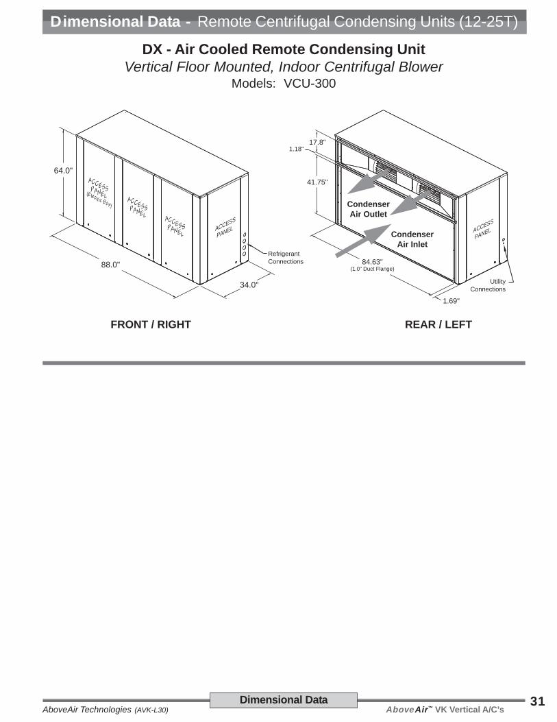
Models: VCU-300
84.63"(1.0" Duct Flange)
41.75"
17.8"
ACCESSPANEL(Electric Box)ACCESSPANEL
ACCESS
PANEL
ACCESSPANELACCESS
PANEL
FRONT / RIGHT REAR / LEFT
CondenserAir Inlet
CondenserAir Outlet
UtilityConnections
1.69"
34.0"
88.0"
64.0"
RefrigerantConnections
1.18"
Dimensional Data - Remote Centrifugal Condensing Units (12-25T)

A boveAir™ VK Vertical A /C ’s AboveAir Technologies (AVK-L30) 32 Dimensi onal Data
D imensi on al Data - Outdoor, R emote Air C ooled C ondensers
Remote Outdoor Propeller FanAir Cooled Condensers
WP2 - 084, 108 & 132
66"
64 5/8 "32"
11/16"
29 3/8 "
42.75"(Overall)
48"2.25"
18.25 "
45"48.5"
52.5"4.875"
Control Panel
Lifting Hole s9/16" Dia (4)
9/16" Dia (4)Mounting Holes
WP1 - 108, 132 & 156
WP2 - 204, 252, 264, 336 & 396
98.25 "
6"
Cont rol PanelReturn
Bend Co ver
42.75 "
18.25 "
96.0 "1.13 "
Lifting Hole s1.5" Dia (Typ.)
45.0 "48.0 "

AboveAir™ VK Vertical A/C’sAboveAir Technologies (AVK-L30)33
Blank Page

AboveAir™ VK Vertical A/C’s AboveAir Technologies (AVK-L30)34 VK-Series
VK-VerticalTM Comfort A/C Series

AboveAir™ VK Vertical A/C’sAboveAir Technologies (AVK-L30)35
Model Nomenclature - VKTM Vertical Series
Model Nomenclature
Model Nomenclature
a: VK - VK Vertical Floor Mounted Series
b: A - DX, Air Cooled - Packaged Self-Containted C - Chilled Water E - DX, Evaporator with Compressor G - DX, Glycol Cooled - Packaged Self-Containted H - DX, Air Handling Unit W - DX, Water Cooled - Packaged Self-Containted
c: 048 = 4.0 Tons; 060 = 5.0 Tons; 072 = 6.0 Tons; 096 = 8.0 Tons; 120 = 10.0 Tons; 144 = 12.0 Tons; 180 = 15.0 Tons; 240 = 20.0 Tons 300 = 25.0 Tons; 360 = 30.0 Tons
d: D - Dual DX Circuited Systems Null - Single DX Circuited System (or Chilled Water System)
e: 1 - 208-230V / 1 Ph / 60 Hz 3 - 208-230V / 3 Ph / 60 Hz 4 - 460-480V / 3 Ph / 60 Hz 5 - 575V / 3 Ph / 60 Hz 7 - 277V / 1 Ph / 60 Hz
f: 00 - No Heat E1 - Electric Heat 1-Stage (Factory Unit Mtd) E2 - Electric Heat 2-Stages (Factory Unit Mtd) ES - SCR Fired Electric Heat (Factory Unit Mtd) HE - Heat Pump with Internal Auxiliary Electric Heat HG - Hot Gas Reheat HP - Heat Pump w/o Internal Auxiliary Electric Heat HW - Hot Water Heating Coil ST - Steam Heating Coil
g: 0 - NoHumidifier H - ElectrodeCanisterHumidifier
a: V - VK Verical Floor Mounted X - Remote Condenser or Condensing Unit W - Witt HTPG Manufactured Remote Condenser
b: C - DX, Air Cooled, Centrifugal Blower Type G - DX, Glycol Cooled P - DX, Air Cooled, Propeller Fan Type W - DX, Water Cooled
c: 1, 2 ... - Witt Condenser Number of Fans U - DX Condensing Unit X - DX Indoor Condenser
d: Nominal Condenser/Cond Unit Capacity in MBH
e: D - Dual DX Circuited Systems Null - Single DX Circuited System (or Chilled Water System)
f: 1 - 208-230V / 1 Ph / 60 Hz 3 - 208-230V / 3 Ph / 60 Hz 4 - 460-480V / 3 Ph / 60 Hz 5 - 575V / 3 Ph / 60 Hz 7 - 277V / 1 Ph / 60 Hz
g: 00 - None HP - Heat Pump Option
Packaged Systems & Split Evaporators
Remote Condensers & Condensing Units
VK E - 240 D - 4 - E1 0 - AE - 00 - TR - DW - D1 - VAV - - Ca b - c d - e - f g - h - i - j - k - l - m - n - o
V C X - 240 D - 4 - 00 - 00 - SF - DW - 00 - CVF - Ca b c - d e - f - g - h - i - j - k - l - m
h: 00 - No Economizer AE - Air Side Economizer Mixing Box DC - Dual Cool / Alternate Water Source Coil FE - Water/Glycol Side Free Cooling Economizer Coil
i: 00 - None OA - High Percentage Outside-Air (HPOA) System
j: TR - Rear Ducted (or Free) Return w/ Top Ducted Evap Disch FR - Rear Ducted (or Free) Return w/ Front Ducted Evap Disch TF - Flip / Reverse Top Evap: Front Ducted (or Free) Return w/ Top Ducted Evap Air Discharge FF - Flip / Reverse Top Evap: Front Ducted (or Free) Return w/ Rear Ducted Evap Air Discharge
k: Null - Single Wall Cabinet Construction DW - Double Wall Cabinet Construction
l: 00 - None / Not Applicable Null - Standard Constant Speed Scroll Compressors (Cir-1 & 2) D1 - Digital Scroll Compressor (Circuit-1 Only) Option D2 - Digital Scroll Compressors (Both Circuits-1 & 2) Option
m: Null - Constant Air Volume System (can also use CAV) DCV - Demand Control Variable Air Volume System Option EVF - Evap Motor VFD for Balancing Purposes Option VAV - Variable Air Volume (Multi-Zone) System Option SZV - Single Zone Variable Air Volume System Option
n: Null - Not Applicable CVF - Low Ambient Condenser Blower VFD Option
o: A, B ... - VK Cabinet Frame Size (see VK Dimensional Drawings)
h: 00 - None OA - High Percentage Outside-Air (HPOA) System
i: SF - Ducted Std “Same-Face” Cond Air Pattern MI - Ducted “Mirror-Image Same-Face” Cond Air Pattern ZST - Ducted “Z” Straight-Thru Cond Air Pattern TT - Ducted “Top Inlet & Top Outlet” Cond Air Pattern FT - Ducted “Front Inlet & Top Outlet” Cond Air Pattern
j: Null - Single Wall Cabinet Construction DW - Double Wall Cabinet Construction
k: 00 - None / Not Applicable Null - Standard Constant Speed Scroll Compressors (Cir-1 & 2) D1 - Digital Scroll Compressor (Circuit-1 Only) Option D2 - Digital Scroll Compressors (Both Circuits-1 & 2) Option
l: Null - Not Applicable CVF - Low Ambient Condenser VFD Option FCS - Low Ambient Fan Cycling Option FLD - Low Ambient Flooded Condennser Option P66 - Low Ambient Variable Speed Fan via JCI p266 Option
m: Null - Not Applicable A, B ... - VK or HK Cabinet Frame Size (see Eng Manuals)

AboveAir™ VK Vertical A/C’s AboveAir Technologies (AVK-L30)36
I n n o v a t i v e H VA C S o l u t i o n s
5179 Mountville RoadFrederick, Maryland 21703, U.S.A.
Phone: 301-874-1130, Facsimile: 301-874-1131
Email: [email protected]
Copyright 10/14Form: AVK-L30
Specifications are subject tochange without notice.
www.aaaaabobobobobovvvvveaireaireaireaireair.com
Comfort - Packaged & SplitVertical Floor Mounted
Air Conditioners(1 to 45 Tons)
VK-MissionCriticalTM - Up-Flow & Down-Flow
Vertical Floor Mounted Computer RoomAir Conditioners
(1 to 30 Tons)
Remote Air CooledCondensers, Condensing Units
& Glycol Drycoolers(1 to 180 Tons of THR)
Precision - Vertical FloorConsole Mounted Air Condi-
tioners(1 to 30 Tons)
High-Static BD “Ducted”Ceiling Mounted A/C’s
(1 to 30 Tons)
2x4 “Spot-Cool & Ducted”Ceiling Mounted A/C’s
(1 to 3 Tons)
Single, Dual & TriplexGlycol Pump Packages
(1/2 to 50 HP)
Ceiling Ceiling Ceiling Ceiling Ceiling Air ConditionerAir ConditionerAir ConditionerAir ConditionerAir ConditionersssssSpotSpotSpotSpotSpotCoolCoolCoolCoolCool
™ - 2x4 T-Bar “Spot-Cool & Ducted”Comfort & Precision Ceiling Mounted A/C’s
HKHKHKHKHK ™ HorizHorizHorizHorizHorizontalontalontalontalontal - Hi-Static Ducted Comfort &
Precision Ceiling Mounted A/C’s
HKHKHKHKHK-O-O-O-O-OAAAAA ™ - Horizontal Up to 100% DOAS High-
Percentage Outside Air Ceiling Mounted A/C’s
FFFFFloor loor loor loor loor Air ConditionerAir ConditionerAir ConditionerAir ConditionerAir ConditionersssssMissionMissionMissionMissionMissionCriticalCriticalCriticalCriticalCritical
™ - Precision Vertical FloorMounted Computer Room A/C’s
VKVKVKVKVK™ VVVVVerererererticalticalticalticaltical - SCAV, Vertical Floor MountedSelf-Contained & Split Comfort Constant Air Volumeand Variable Air Volume (VAV) A/C’s & Heat Pumps
VKVKVKVKVK-O-O-O-O-OAAAAA ™ - Vertical Up to 100% DOAS High-
Percentage Outside Air Vertical Floor Mounted A/C’s
VKVKVKVKVK™ ConsoleConsoleConsoleConsoleConsole - Vertical Floor Console MountedSelf-Contained & Split A/C’s & Heat Pumps
RRRRRemote Heaemote Heaemote Heaemote Heaemote Heat Rt Rt Rt Rt Rejectionejectionejectionejectionejection
FluidFluidFluidFluidFluidCoolCoolCoolCoolCool ™ - Indoor & Outdoor Remote Glycol
Drycoolers
PumpPumpPumpPumpPumpAllAllAllAllAll ™ - Single, Dual & Triplex Standard &
Variable (VFD) Speed Glycol Pump Packages
Related Documents