1 ENGINE MODEL CUMMINS QSL9 Type Water cooled, 4 cycle Diesel, 6-Cylinders in line, direct injection, turbocharged, charged air cooled and low emission Rated flywheel horse power SAE J1995 (gross) 282 HP (210 kW) / 1,750 rpm J1349 (net) 268 HP (200 kW) / 1,750 rpm DIN 6271/1 (gross) 286 PS (210 kW) / 1,750 rpm 6271/1 (net) 272 PS (200 kW) / 1,750 rpm Max. torque 123.7 kgf.m (895 lbf.ft) / 1,500 rpm Bore x stroke 114 x 145 mm (4.5” x 5.7”) Piston displacement 8,900 cc (543 in 3 ) Batteries 2 x 12 V x 160 AH Starting motor 24 V; 7.8 kW Alternator 24 V; 95 Amp HYDRAULIC SYSTEM MAIN PUMP Type Variable displacement tandem-axial piston pumps Max. flow 2 x 270 ℓ /min (71.3 US gpm / 59.4 UK gpm) Sub-pump for pilot circuit Gear pump Cross-sensing and fuel saving pump system HYDRAULIC MOTORS Travel Two speed axial piston motor with brake valve and parking brake Swing Axial piston motor with automatic brake RELIEF VALVE SETTING Implement circuits 350 kgf/cm 2 (4,978 psi) Travel 350 kgf/cm 2 (4,978 psi) Power boost (boom, arm, bucket) 380 kgf/cm 2 (5,404 psi) Swing circuit 300 kgf/cm 2 (4,409 psi) Pilot circuit 40 kgf/cm 2 (568 psi) Service valve Installed HYDRAULIC CYLINDERS No. of cylinder- bore x stroke Boom: 2-150 x 1,480 mm (5.9” x 58.3”) Arm: 1-160 x 1,685 mm (6.3” x 66.3”) Bucket: 1-140 x 1,285 mm (5.5” x 50.6”) DRIVES & BRAKES Drive method Fully hydrostatic type Drive motor Axial piston motor, in-shoe design Reduction system Planetary reduction gear Max. drawbar pull 29,500 kgf (65,040 lbf ) Max. travel speed (high) / (low) 5.5 km/hr (3.4 mph) / 3.3 km/hr (2.1 mph) Gradeability 35° (70 %) Parking brake Multi wet disc CONTROL Pilot pressure operated joysticks and pedals with detachable lever provide almost effortless and fatigueless operation. Pilot control Two joysticks with one safety lever (LH): Swing and arm (RH): Boom and bucket (ISO) Traveling and steering Two levers with pedals Engine throttle Electric, Dial type SWING SYSTEM Swing motor Fixed displacement axial pistons motor Swing reduction Planetary gear reduction Swing bearing lubrication Grease-bathed Swing brake Multi wet disc Swing speed 9.4 rpm COOLANT & LUBRICANT CAPACITY Refilling liter US gal UK gal Fuel tank 500 132.1 110.0 Engine coolant 55 14.5 12.1 Engine oil 30 7.9 6.6 Swing device 11 1.6 1.3 Final drive (each) 5.5 2.1 1.8 Hydraulic system (including tank) 330 87.2 72.6 Hydraulic tank 190 50.2 41.8 UNDERCARRIAGE The X-leg type center frame is integrally welded with reinforced box-section track frames. The undercarriage includes lubricated rollers, idlers, track adjusters with shock absorbing springs and sprockets, and a track chain with double or triple grouser shoes. Center frame X - leg type Track frame Pentagonal box type No. of shoes on each side 48 No. of carrier rollers on each side 2 No. of track rollers on each side 9 No. of rail guards on each side 2 OPERATING WEIGHT (APPROXIMATE) Operating weight, including 6,450 mm (21’ 2”) boom, 3,200 mm (10’ 6”) arm, SAE heaped 1.44m 3 (1.88 yd 3 ) bucket, lubricant, coolant, full fuel tank, full hydraulic tank, and all standard equipments. MAJOR COMPONENT WEIGHT Upperstructure 8,120 kg (17,900 lb) Boom (with arm cylinder) 3,030 kg (6,680 lb) Arm (with bucket cylinder) 1,770 kg (3,900 lb) OPERATING WEIGHT Shoes Operating weight Ground pressure Type Width mm (in) kg (lb) kgf/cm 2 (psi) Triple grouser 600 (24”) R330LC-9A 33,000 (72,750) 0.63 (8.96) R330NLC-9A 32,800 (72,310) 0.63 (8.96) R330LC-9A H/W 35,500 (78,260) 0.68 (9.67) 700 (28”) R330LC-9A 33,600 (74,070) 0.55 (7.83) R330LC-9A H/W 36,100 (79,590) 0.59 (8.39) 800 (32”) R330LC-9A 34,000 (74,960) 0.49 (6.57) R330LC-9A H/W 36,500 (80,470) 0.50 (7.14) 900 (36”) R330LC-9A 34,400 (75,840) 0.44 (6.26) Double grouser 700 (28”) R330LC-9A H/W 37,010 (81,590) 0.60 (8.53) Specifications R330LC-9A

Welcome message from author
This document is posted to help you gain knowledge. Please leave a comment to let me know what you think about it! Share it to your friends and learn new things together.
Transcript
1
EnginE
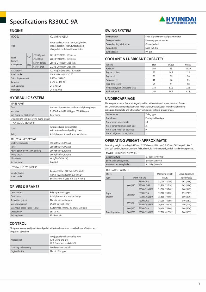
Model CuMMins Qsl9
TypeWater cooled, 4 cycle diesel, 6-Cylindersin line, direct injection, turbocharged,charged air cooled and low emission
Rated flywheel horse power
sAeJ1995 (gross) 282 HP (210 kW) / 1,750 rpm
J1349 (net) 268 HP (200 kW) / 1,750 rpm
din6271/1 (gross) 286 Ps (210 kW) / 1,750 rpm
6271/1 (net) 272 Ps (200 kW) / 1,750 rpm
Max. torque 123.7 kgf.m (895 lbf.ft) / 1,500 rpm
Bore x stroke 114 x 145 mm (4.5” x 5.7”)
Piston displacement 8,900 cc (543 in3)
Batteries 2 x 12 V x 160 AH
starting motor 24 V; 7.8 kW
Alternator 24 V; 95 Amp
Hydraulic systEm
MAin PuMPType Variable displacement tandem-axial piston pumps
Max. flow 2 x 270 ℓ /min (71.3 us gpm / 59.4 uK gpm)
sub-pump for pilot circuit Gear pump
Cross-sensing and fuel saving pump system
HydRAuliC MoToRs
TravelTwo speed axial piston motor with brake valve and parking brake
swing Axial piston motor with automatic brake
Relief VAlVe seTTinGimplement circuits 350 kgf/cm2 (4,978 psi)
Travel 350 kgf/cm2 (4,978 psi)
Power boost (boom, arm, bucket) 380 kgf/cm2 (5,404 psi)
swing circuit 300 kgf/cm2 (4,409 psi)
Pilot circuit 40 kgf/cm2 (568 psi)
service valve installed
HydRAuliC CylindeRs
no. of cylinder- bore x stroke
Boom: 2-150 x 1,480 mm (5.9” x 58.3”)
Arm: 1-160 x 1,685 mm (6.3” x 66.3”)
Bucket: 1-140 x 1,285 mm (5.5” x 50.6”)
drivEs & BrakEs
drive method fully hydrostatic type
drive motor Axial piston motor, in-shoe design
Reduction system Planetary reduction gear
Max. drawbar pull 29,500 kgf (65,040 lbf )
Max. travel speed (high) / (low) 5.5 km/hr (3.4 mph) / 3.3 km/hr (2.1 mph)
Gradeability 35° (70 %)
Parking brake Multi wet disc
controlPilot pressure operated joysticks and pedals with detachable lever provide almost effortless and fatigueless operation.
Pilot controlTwo joysticks with one safety lever (lH): swing and arm(RH): Boom and bucket (iso)
Traveling and steering Two levers with pedals
engine throttle electric, dial type
swing systEm
swing motor fixed displacement axial pistons motor
swing reduction Planetary gear reduction
swing bearing lubrication Grease-bathed
swing brake Multi wet disc
swing speed 9.4 rpm
coolant & luBricant capacity
Refilling liter us gal uK gal
fuel tank 500 132.1 110.0
engine coolant 55 14.5 12.1
engine oil 30 7.9 6.6
swing device 11 1.6 1.3
final drive (each) 5.5 2.1 1.8
Hydraulic system (including tank) 330 87.2 72.6
Hydraulic tank 190 50.2 41.8
undErcarriagEThe X-leg type center frame is integrally welded with reinforced box-section track frames. The undercarriage includes lubricated rollers, idlers, track adjusters with shock absorbing springs and sprockets, and a track chain with double or triple grouser shoes.
Center frame X - leg type
Track frame Pentagonal box type
no. of shoes on each side 48
no. of carrier rollers on each side 2
no. of track rollers on each side 9
no. of rail guards on each side 2
opErating wEigHt (approximatE)operating weight, including 6,450 mm (21’ 2”) boom, 3,200 mm (10’ 6”) arm, sAe heaped 1.44m3 (1.88 yd3) bucket, lubricant, coolant, full fuel tank, full hydraulic tank, and all standard equipments.
MAJoR CoMPonenT WeiGHTupperstructure 8,120 kg (17,900 lb)
Boom (with arm cylinder) 3,030 kg (6,680 lb)
Arm (with bucket cylinder) 1,770 kg (3,900 lb)
oPeRATinG WeiGHTshoes operating weight Ground pressure
Type Width mm (in) kg (lb) kgf/cm2 (psi)
Triplegrouser
600 (24”)
R330lC-9A 33,000 (72,750) 0.63 (8.96)
R330nlC-9A 32,800 (72,310) 0.63 (8.96)
R330lC-9A H/W 35,500 (78,260) 0.68 (9.67)
700 (28”)R330lC-9A 33,600 (74,070) 0.55 (7.83)
R330lC-9A H/W 36,100 (79,590) 0.59 (8.39)
800 (32”)R330lC-9A 34,000 (74,960) 0.49 (6.57)
R330lC-9A H/W 36,500 (80,470) 0.50 (7.14)
900 (36”) R330lC-9A 34,400 (75,840) 0.44 (6.26)
double grouser 700 (28”) R330lC-9A H/W 37,010 (81,590) 0.60 (8.53)
specifications r330lc-9a
2
0.90 (1.18)
1.14 (1.49)
1.44 (1.88)
1.74 (2.28)
2.10 (2.75)
1.44 (1.88)
1.44 (1.88)
1.73 (2.26)
0.80 (1.05)
1.00 (1.31)
1.25 (1.63)
1.50 (1.96)
1.80 (2.35)
1.25 (1.63)
1.25 (1.63)
1.50 (1.96)
950 (37.4)
1,110 (43.7)
1,380 (54.3)
1,620 (63.8)
1,910 (75.2)
1,470 (57.9)
1,470 (57.9)
1,710 (67.3)
1,070 (42.1)
1,230 (48.4)
1,500 (59.1)
1,740 (68.5)
2,030 (79.9)
870 (1,920)
980 (2,160)
1,110 (2,450)
1,230 (2,710)
1,370 (3,020)
1,380 (3,040)
1,470 (3,240)
1,610 (3,550)
mm (ft.in)
kg (lb)
mm (ft.in)
kg (lb)
2,200 (7’ 3”)
1,560 (3,440)
189.3 [205.5]
19,300 [20,950]
42,550 [46,200]
211.8 [230.0]
21,600 [23,450]
47,620 [51,700]
196.6 [213.4]
20,000 [21,760]
44,190 [47,980]
202.8 [220.2]
20,700 [22,450]
45,600 [49,510]
189.3 [205.5]
19,300 [20,950]
42,550 [46,200]
211.8 [230.0]
21,600 [23,450]
47,620 [51,700]
178.9 [194.2]
18,200 [19,810]
40,220 [43,670]
185.1 [201.0]
18,900 [20,500]
41,620 [45,190]
189.3 [205.5]
19,300 [20,950]
42,550 [46,200]
211.8 [230.0]
21,600 [23,450]
47,620 [51,700]
143.2 [155.5]
14,600 [15,850]
32,190 [34,950]
147.1 [159.7]
15,000 [16,290]
33,070 [35,900]
189.3 [205.5]
19,300 [20,950]
42,550 [46,200]
211.8 [230.0]
21,600 [23,450]
47,620 [51,700]
119.6 [129.9]
12,200 [13,240]
26,890 [29,190]
122.7 [133.3]
12,515 [13,590]
27,590 [29,950]
2,500 (8’ 2”)
1,650 (3,640)
3,200 (10’ 6”)
1,770 (3,900)
6,450 (21’ 2”)3,030 (6,680)
4,050 (13’ 3”)
1,870 (4,120)
SAE
kN
kgf
lbf
ISO
kN
kgf
lbf
SAE
kN
kgf
lbf
ISO
kN
kgf
lbf
0.90 (1.18) 1.14 (1.49) 1.44 (1.88)1.73 (2.26)
1.44 (1.88) 1.74 (2.28)2.10 (2.75)
1.44 (1.88)
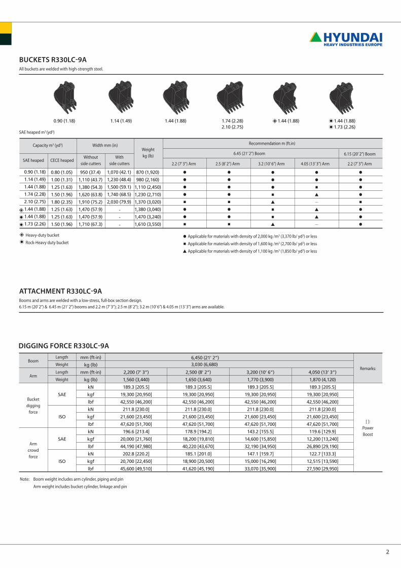
BuckEts r330lc-9aAll buckets are welded with high-strength steel.
sAe heaped m3 (yd3)
attacHmEnt r330lc-9aBooms and arms are welded with a low-stress, full-box section design. 6.15 m (20’ 2”) & 6.45 m (21’ 2”) booms and 2.2 m (7’ 3”); 2.5 m (8’ 2”); 3.2 m (10’ 6”) & 4.05 m (13’ 3”) arms are available.
note: Boom weight includes arm cylinder, piping and pin
Arm weight includes bucket cylinder, linkage and pin
digging forcE r330lc-9a
Capacity m3 (yd3)
sAe heaped CeCe heaped
Width mm (in)
Without side cutters
With side cutters
Weight kg (lb)
Recommendation m (ft.in)
6.45 (21’ 2”) Boom
2.2 (7’ 3”) Arm 3.2 (10’ 6”) Arm 2.5 (8’ 2”) Arm 4.05 (13’ 3”) Arm
Heavy-duty bucket
Rock-Heavy duty bucketApplicable for materials with density of 2,000 kg /m3 (3,370 lb/ yd3) or less
Applicable for materials with density of 1,600 kg /m3 (2,700 lb/ yd3) or less
Applicable for materials with density of 1,100 kg /m3 (1,850 lb/ yd3) or less
2.2 (7’ 3”) Arm
6.15 (20’ 2”) Boom
Boomlength
Weight
Arm
Bucketdigging
force
Armcrowdforce
[ ]:PowerBoost
Remarks:length
Weight
3
A
A’
B
B’
C
D
E
F
2,200(7’ 3”)
10,330(33’ 11”)
10,110(33’ 2”)
6,370(20’ 11”)
6,160(20’ 3”)
5,980(19’ 7”)
10,220(33’ 6”)
7,050(23’ 2”)
4,700(15’ 5”)
2,500(8’ 2”)
10,550 (34’ 7”)
10,330(33’ 11”)
6,670(21’ 11”)
6,470(21’ 3”)
5,920(19’ 5”)
10,170(33’ 4”)
7,050(23’ 2”)
4,500(14’ 9”)
3,200(10’ 6”)
11,140(36’ 7”)
10,940(35’ 11”)
7,370(24’ 2”)
7,210(23’ 8”)
6,360(20’ 10”)
10,310(33’ 10”)
7,240(23’ 9”)
4,470(14’ 8”)
4,050(13’ 3”)
2,200(7’ 3”)
6,150(20’ 2”)
11,950 (39’ 2”)
10,020(32’ 10”)
11,760(38’ 7”)
9,800(32’ 2”)
8,220(26’ 12”)
6,160(20’ 3”)
8,080(26’ 6”)
5,950(19’ 6”)
7,260(23’ 10”)
5,710(18’ 9”)
10,710(35’ 2”)
9,940(32’ 7”)
7,630(25’ 0”)
6,780(22’ 3”)
4,470(14’ 8”)
4,520(14’ 10”)
6,450(21’ 2”)
R330LC-9A
R330NLC-9A
R330LC-9A
R330NLC-9A
A
B
C
D
D’
E
F
G
H
4,030 (13’ 3”)
4,030 (13’ 3”)
4,940 (16’ 2”)
1,200 (3’ 11”)
3,560 (11’ 8”)
3,504 (11’ 6”)
2,980 (9’ 9”)
3,130 (10’ 3”)
500 (1’ 8”)
2,680 (8’ 10”)
2,390 (7’ 10”)
ED (D')
LK
HBA
I
J F
GC
600(24”)
K
L
3,200(10’ 6”)
2,990(9’ 10”)
- - -
700(28”)
3,300(10’ 10”)
800(32”)
3,400(11’ 2”)
900(36”)
3,500(11’ 16”)
R330NLC-9A
R330LC-9A
I
J
2,200(7’ 3”)
11,470(37’ 8”)
3,640(11’ 11”)
2,500(8’ 2”)
11,340(37’ 2”)
3,670(12’ 0”)
3,200(10’ 6”)
11,220 (36’ 10”)
3,380(11’ 1”)
4,050(13’ 3”)
2,200(7’ 3”)
11,220 (36’ 10”)
11,170(36’ 8”)
3,860(12’ 8”)
3,680(12’ 1”)
6,450
(21’ 2”)
6,150
(20’ 2”)
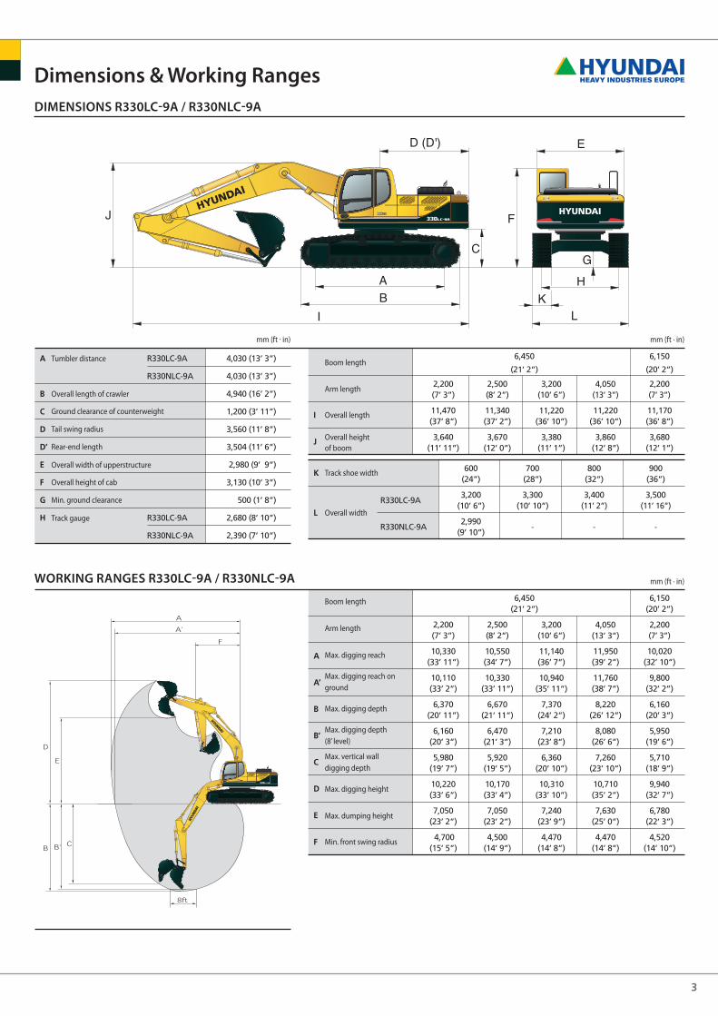
dimEnsions r330lc-9a / r330nlc-9a
working rangEs r330lc-9a / r330nlc-9a
dimensions & working ranges
mm (ft · in)mm (ft . in)
mm (ft · in)
Tumbler distance Boom length
Arm length
overall length
overall heightof boom
Track shoe width
overall width
overall length of crawler
Ground clearance of counterweight
Tail swing radius
Rear-end length
overall width of upperstructure
overall height of cab
Min. ground clearance
Track gauge
Boom length
Arm length
Max. digging reach
Max. digging reach on ground
Max. digging depth
Max. digging depth (8’ level)
Max. vertical wall digging depth
Max. digging height
Max. dumping height
Min. front swing radius
4
700 (28”)
I
J
2,200(7’ 3”)
11,460(37’ 7”)
3,740(12’ 3”)
2,500(8’ 2”)
11,340(37’ 2”)
3,760(12’ 4”)
3,200(10’ 6”)
11,150 (36’ 7”)
3,360(11’ 0”)
4,050(13’ 3”)
2,200(7’ 3”)
11,240 (36’ 11”)
11,160(36’ 7”)
3,810(12’ 6”)
3,780(12’ 5”)
6,450
(21’ 2”)
6,150
(20’ 2”)
A
A’
B
B’
C
D
E
F
2,200(7’ 3”)
10,330(33’ 11”)
10,040(32’ 11”)
6,100(20’ 0”)
5,890(19’ 4”)
5,700(18’ 8”)
10,500(34’ 5”)
7,330(24’ 1”)
4,700(15’ 5”)
2,500(8’ 2”)
10,550 (34’ 7”)
10,270(33’ 8”)
6,400(20’ 12”)
6,200(20’ 4”)
5,650(18’ 6”)
10,450(34’ 3”)
10,450(34’ 3”)
4,500(14’ 9”)
3,200(10’ 6”)
11,140(36’ 7”)
10,880(35’ 8”)
7,100(23’ 4”)
6,940(22’ 9”)
6,080(19’ 11”)
10,590(34’ 9”)
7,520(24’ 8”)
4,470(14’ 8”)
4,050(13’ 3”)
2,200(7’ 3”)
6,150(20’ 2”)
11,950 (39’ 2”)
10,020(32’ 10”)
11,710(38’ 5”)
9,730(31’ 11”)
7,950(26’ 1”)
5,880(19’ 3”)
7,950(26’ 1”)
5,680(18’ 8”)
6,980(22’ 11”)
5,440(17’ 10”)
10,990(36’ 1”)
10,220(33’ 6”)
7,910(25’ 11”)
7,060(23’ 2”)
4,470(14’ 8”)
4,520(14’ 10”)
6,450(21’ 2”)
A
B
C
D
D’
E
F
G
H
4,030 (13’ 3”)
4,940 (16’ 2”)
1,500 (4’ 11”)
3,560 (11’ 8”)
3,504 (11’ 6”)
2,980 (9’ 9”)
3,390 (11’ 1”)
765 (2’ 6”)
2,870 (9’ 5”)
ED (D')
LK
HBA
I
J F
GC
3,470(11’ 5”)
3,570 (11’ 9”)
3,670(12’ 0”)
3,570(11’ 9”)
700 (28”) 800 (32”)K
L
600 (24”)
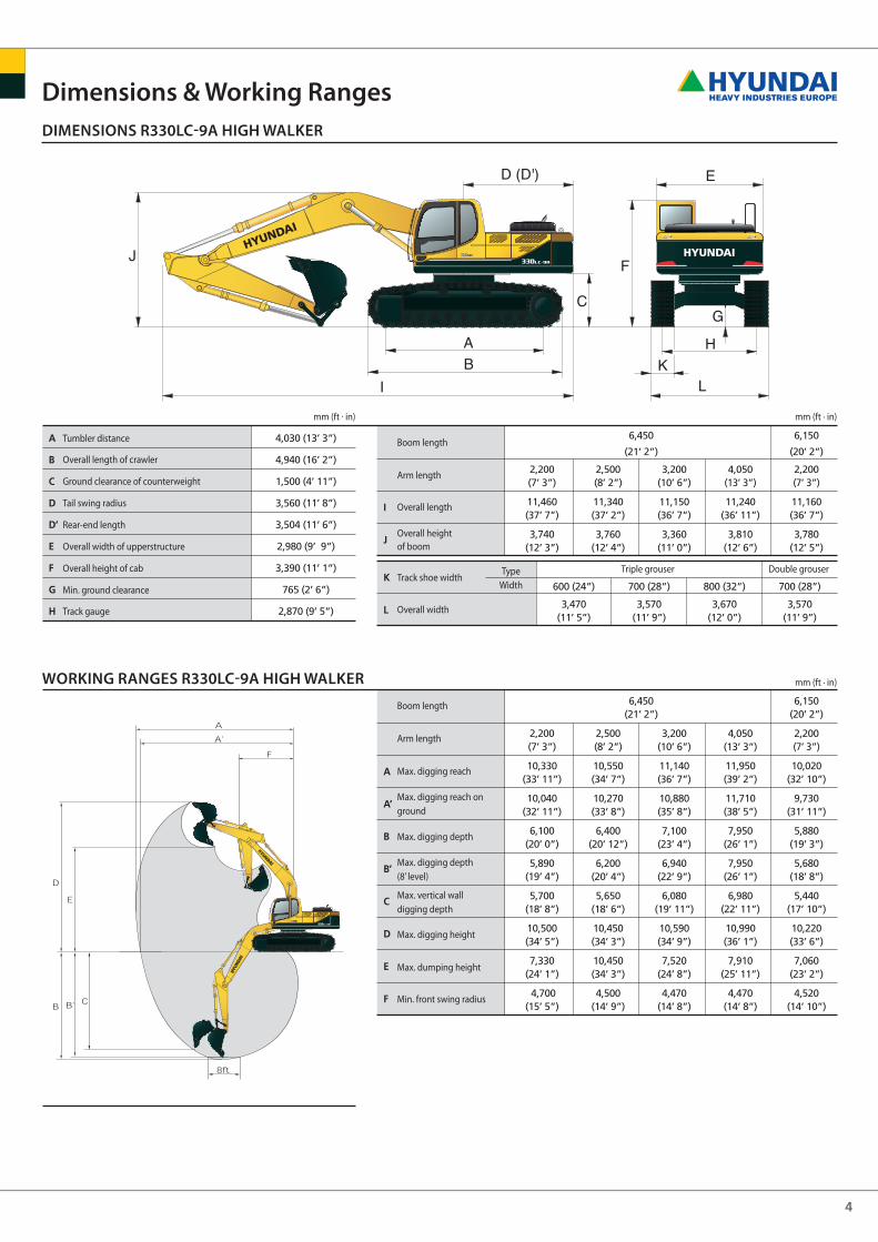
dimEnsions r330lc-9a HigH walkEr
working rangEs r330lc-9a HigH walkEr
dimensions & working ranges
mm (ft · in)mm (ft . in)
mm (ft · in)
Tumbler distance
overall length of crawler
Ground clearance of counterweight
Tail swing radius
Rear-end length
overall width of upperstructure
overall height of cab
Min. ground clearance
Track gauge
Boom length
Arm length
Max. digging reach
Max. digging reach on ground
Max. digging depth
Max. digging depth (8’ level)
Max. vertical wall digging depth
Max. digging height
Max. dumping height
Min. front swing radius
Boom length
Arm length
overall length
overall heightof boom
Track shoe widthType
Width
overall width
Triple grouser double grouser
5
3.0 m (10 ft) 4.5 m (15 ft) 6.0 m (20 ft) 7.5 m (25 ft)
m (ft )
7.5 m(25 ft)6.0 m(20 ft)4.5 m(15 ft)3.0 m(10 ft)1.5 m(5 ft)
-1.5 m(-5 ft)-3.0 m(-10 ft)-4.5 m(-15 ft)
kglbkglbkglbkglbkglbkglbkglbkglbkglb
*14420*31790*22130*48790*17840*39330
*14420*31790*22130*48790*17840*39330
*12360*27250
*18470*40720*17890*39440*16390*36130*13400*29540
*12360*27250
1147025290115202540011720258401213026740
*8220*18120*9550
*21050*11160*246001230027120120202650011960263701207026610
*8220*18120
8590189408050
177507610
167807370
162507310
161207410
16340
*7700*16980*8250
*181908860
195308600
189608430
185808380
18470
6100134505910
130305660
124805420
119505260
116005220
11510
*7120*15700
6850151006100
134505770
127205740
126506030
132906770
14930*7930
*17480
5470120604420974038908580363080003600794037808330427094105330
11750
8.07(26.5)
8.95(29.4)
9.47(31.1)
9.70(31.8)
9.66(31.7)
9.34(30.6)
8.72(28.6)
7.70(25.3)
3.0 m (10 ft) 4.5 m (15 ft) 6.0 m (20 ft) 7.5 m (25 ft) 9.0 m (30 ft)
m (ft )
7.5 m(25 ft)6.0 m(20 ft)4.5 m(15 ft)3.0 m(10 ft)1.5 m(5 ft)
-1.5 m(-5 ft)-3.0 m(-10 ft)-4.5 m(-15 ft)
kglbkglbkglbkglbkglbkglbkglbkglbkglb
*15010*33090*22800*50270*19110*42130
*15010*33090*22800*50270*19110*42130
*11600*25570*15130*33360*17590*38780*18360*40480*18010*39710*16720*36860*14080*31040
*11600*25570125302762011670257301138025090113702507011550254601193026300
*9120*20110*10770*23740*12210*26920119702639011860261501195026350
*10340*22800
8640190508070
177907600
167607310
161207220
159207300
160907590
16730
*7320*16140*7930
*17480*8770
*193308570
188908380
184708300
18300
6140135405930
130705650
124605390
11880 5210
114905150
11350
637014040
39908800
*6720*14820
6560144605860
129205540
122105500
121305760
127006410
141307830
17260*7300
*16090
5180114204220930037208200347076503430756035907910402088604950
109107270
16030
8.34(27.4)
9.19(30.2)
9.70(31.8)
9.92(32.5)
9.88(32.4)
9.57(31.4)
8.97(29.4)
7.98(26.2)
6.42(21.1)
1.5 m (5 ft) 3.0 m (10 ft) 4.5 m (15 ft) 6.0 m (20 ft) 7.5 m (25 ft) 9.0 m (30 ft)
m (ft )
7.5 m(25 ft)6.0 m(20 ft)4.5 m(15 ft)3.0 m(10 ft)1.5 m(5 ft)
-1.5 m(-5 ft)-3.0 m(-10 ft)-4.5 m(-15 ft)-6.0 m(-20 ft)
kglbkglbkglbkglbkglbkglbkglbkglbkglbkglb
*11380*25090*15350*33840
*11380*25090*15350*33840
*10240*22580*14470*31900*19470*42920*21820*48100
*10240*22580*14470*31900*19470*42920*21820*48100
*13400*29540*16400*36160*17910*39480*18150*40010*17370*38290*15410*33970*11340*25000
129302851011850261201132024960111702463011250248001153025420
*11340*25000
*8090*17840*9820
*21650*11460*25260119302630011730258601173025860
*11430*25200
*8090*17840
8190180607640
168407270
160307090
156307090
156307270
16030
*5240*11550*6500
*14330*7190
*15850*8110
*178808570
188908320
183408180
180308190
18060
*5240*11550
6260138006000
132305690
125405380
118605150
113505030
110905040
11110
*5440*11990
6520143706350
140006210
13690
42809440412090803960873038308440
*5970*13160
5850129005270
116204990
110004950
109105130
113105620
123906640
14640*7480
*16490
44909900373082203310730030906810304067003150694034707650414091305630
12410
9.06(29.7)
9.84(32.3)10.31(33.8)10.52(34.5)10.48(34.4)10.19(33.4)
9.63(31.6)
8.74(28.7)
7.37(24.2)
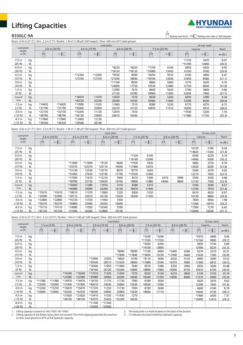
r330lc-9a Rating over-front Rating over-side or 360 degrees
lifting capacities
Boom : 6.45 m (21’ 2”) / Arm : 2.2 m (7’ 3”) / Bucket : 1.44 m3 (1.88 yd3) sAe heaped / shoe : 600 mm (24”) triple grouser
load pointheightm (ft)
load radius At max. reachCapacity Reach
Groundline
Boom : 6.45 m (21’ 2”) / Arm : 2.5 m (8’ 2”) / Bucket : 1.44 m3 (1.88 yd3) sAe heaped / shoe : 600 mm (24”) triple grouser
load pointheightm (ft)
load radius At max. reachCapacity Reach
Groundline
Boom : 6.45 m (21’ 2”) / Arm : 3.2 m (10’ 6”) / Bucket : 1.44 m3 (1.88 yd3) sAe heaped / shoe : 600 mm (24”) triple grouser
load pointheightm (ft)
load radius At max. reachCapacity Reach
Groundline
1. lifting capacity is based on sAe J1097, iso 10567.2. lifting capacity of the Robex series does not exceed 75% of the tipping load with the machine
on firm, level ground or 87% of full hydraulic capacity.
3. The load point is a hook located on the back of the bucket.4. (*) indicates the load limited by hydraulic capacity.
6
1.5 m (5 ft) 3.0 m (10 ft) 4.5 m (15 ft) 6.0 m (20 ft) 7.5 m (25 ft) 9.0 m (30 ft)
m (ft )
7.5 m(25 ft)6.0 m(20 ft)4.5 m(15 ft)3.0 m(10 ft)1.5 m(5 ft)
-1.5 m(-5 ft)-3.0 m(-10 ft)-4.5 m(-15 ft)-6.0 m(-20 ft)
kglbkglbkglbkglbkglbkglbkglbkglbkglbkglb
*9850*21720*13020*28700*16670*36750
*9850*21720*13020*28700*16670*36750
*18220*40170*10440*23020*10810*23830*13390*29520*16980*37430*21800*48060*20030*44160
*18220*40170*10440*23020*10810*23830*13390*29520*16980*37430*21800*48060*20030*44160
*11250*24800*14750*32520*17060*37610*18030*39750*17900*39460*16680*36770*13950*30750
*11250*24800123102714011520254001117024630111002447011260248201164025660
*8610*18980*10470*23080*11950*26350117302586011620256201170025790
*10120*22310
8460186507840
172807360
162307080
156106990
154107060
155607340
16180
*6270*13820*7280
*16050*8360
*184308350
184108150
179708070
177908150
17970
6160135805810
128105460
120405180
114204990
110004920
108505000
11020
*4530*9990*5750
*12680*6530
*144006380
140706200
136706080
134006070
13380
45109940437096304180922039808770381084003710818037008160
*5250*11570
5050111304610
101604380966043309550446098304810
106005510
121506910
15230*6790
*14970
3750827031807010285062802670589026205780269059302920644033807450431095006610
14570
10.00(32.8)10.71(35.1)11.13(36.5)11.32(37.1)11.29(37.0)11.03(36.2)10.52(34.5)
9.72(31.9)
8.53(28.0)
6.71(22.0)
3.0 m (10 ft) 4.5 m (15 ft) 6.0 m (20 ft) 7.5 m (25 ft)
m (ft )
7.5 m(25 ft)6.0 m(20 ft)4.5 m(15 ft)3.0 m(10 ft)1.5 m(5 ft)
-1.5 m(-5 ft)-3.0 m(-10 ft)-4.5 m(-15 ft)
kglbkglbkglbkglbkglbkglbkglbkglbkglb
*14420*31790*22140*48810*17840*39330
*14420*317901948042950
*17840*39330
*12360*27250
*18480*40740*17900*39460*16390*36130*13410*29560
1143025200
9360206409400
207209590
211409980
22000
*8220*18120*9550
*21050*11160*246001223026960119502635011880261901200026460
7700169807260
160106740
148606320
139306090
134306030
132906130
13510
*7700*16980*8250
*181908800
194008540
188308370
184508330
18360
5160113804980
109804730
10430450099204350959043109500
*7120*15700
6810150106060
133605730
126305700
125705990
132106730
14840*7930
*17480
46301021037008160322071002990659029606530311068603530778044509810
8.07(26.5)
8.95(29.4)
9.47(31.1)
9.70(31.8)
9.66(31.7)
9.34(30.6)
8.72(28.6)
7.70(25.3)
3.0 m (10 ft) 4.5 m (15 ft) 6.0 m (20 ft) 7.5 m (25 ft) 9.0 m (30 ft)
m (ft )
7.5 m(25 ft)6.0 m(20 ft)4.5 m(15 ft)3.0 m(10 ft)1.5 m(5 ft)
-1.5 m(-5 ft)-3.0 m(-10 ft)-4.5 m(-15 ft)
kglbkglbkglbkglbkglbkglbkglbkglbkglb
*15010*33090*22800*50270*19110*42130
*15010*330901914042200
*19110*42130
*11600*25570*15130*33360*17590*38780*18360*40480*18010*39710*16720*36860*14080*31040
115902555010350228209540
210309270
204409260
204109430
207909780
21560
*9120*20110*10770*23740*12210*26920118902621011790259901187026170
*10340*22800
7300160906760
149006300
138906030
132905940
131006010
132506290
13870
*7320*16140*7930
*17480*8770
*193308520
187808320
183408250
18190
5200114604990
110004720
10410447098504300948042409350
633013960
32807230
*6720*14820
6520143705820
128305500
121305460
120405720
126106370
140407780
17150*7300
*16090
43809660353077803070677028506280280061702930646033007280411090606090
13430
8.34(27.4)
9.19(30.2)
9.70(31.8)
9.92(32.5)
9.88(32.4)
9.57(31.4)
8.97(29.4)
7.98(26.2)
6.42(21.1)
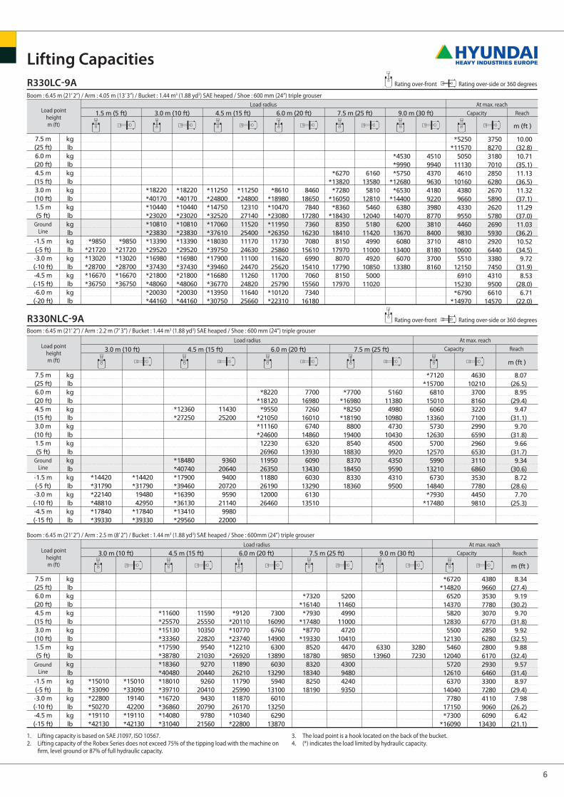
r330lc-9a
r330nlc-9a
lifting capacities
Boom : 6.45 m (21’ 2”) / Arm : 4.05 m (13’ 3”) / Bucket : 1.44 m3 (1.88 yd3) sAe heaped / shoe : 600 mm (24”) triple grouser
load pointheightm (ft)
load radius At max. reachCapacity Reach
Groundline
Boom : 6.45 m (21’ 2”) / Arm : 2.2 m (7’ 3”) / Bucket : 1.44 m3 (1.88 yd3) sAe heaped / shoe : 600 mm (24”) triple grouser
load pointheightm (ft)
load radius At max. reachCapacity Reach
Groundline
Boom : 6.45 m (21’ 2”) / Arm : 2.5 m (8’ 2”) / Bucket : 1.44 m3 (1.88 yd3) sAe heaped / shoe : 600mm (24”) triple grouser
load pointheightm (ft)
load radius At max. reachCapacity Reach
Groundline
1. lifting capacity is based on sAe J1097, iso 10567.2. lifting capacity of the Robex series does not exceed 75% of the tipping load with the machine on
firm, level ground or 87% of full hydraulic capacity.
3. The load point is a hook located on the back of the bucket.4. (*) indicates the load limited by hydraulic capacity.
Rating over-front Rating over-side or 360 degrees
Rating over-front Rating over-side or 360 degrees

7
1.5 m (5 ft) 3.0 m (10 ft) 4.5 m (15 ft) 6.0 m (20 ft) 7.5 m (25 ft) 9.0 m (30 ft)
m (ft )
7.5 m(25 ft)6.0 m(20 ft)4.5 m(15 ft)3.0 m(10 ft)1.5 m(5 ft)
-1.5 m(-5 ft)-3.0 m(-10 ft)-4.5 m(-15 ft)-6.0 m(-20 ft)
kglbkglbkglbkglbkglbkglbkglbkglbkglbkglb
*11380*25090*15350*33840
*11380*25090*15350*33840
*10240*22580*14470*31900*19470*42920*21820*48100
*10240*22580*14470*3190018530408501906042020
*13400*29540*16400*36160*17910*39480*18150*40010*17370*38290*15410*33970*11340*25000
10720236309700
213809210
203009070
200009140
201509400
207209950
21940
*8090*17840*9820
*21650*11460*25260118502612011650256801165025680
*11430*25200
7460164506870
151506340
139805980
131805810
128105810
128105980
13180
*5240*11550*6500
*14330*7190
*15850*8110
*178808520
187808260
182108130
179208130
17920
*5240*11550
5310117105060
111604750
1047044609830423093304120908041209080
*5440*11990
6480142906300
138906170
13600
35607850341075203250717031306900
*5970*13160
5810128105240
115504960
109304910
108205090
112205580
123006590
14530*7480
*16490
37808330310068302710597025105530246054202550562028206220340075004680
10320
9.06(29.7)
9.84(32.3)10.31(33.8)10.52(34.5)10.48(34.4)10.19(33.4)
9.63(31.6)
8.74(28.7)
7.37(24.2)
1.5 m (5 ft) 3.0 m (10 ft) 4.5 m (15 ft) 6.0 m (20 ft) 7.5 m (25 ft) 9.0 m (30 ft)
m (ft )
7.5 m(25 ft)6.0 m(20 ft)4.5 m(15 ft)3.0 m(10 ft)1.5 m(5 ft)
-1.5 m(-5 ft)-3.0 m(-10 ft)-4.5 m(-15 ft)-6.0 m(-20 ft)
kglbkglbkglbkglbkglbkglbkglbkglbkglbkglb
*9850*21720*13020*28700*16670*36750
*9850*21720*13020*28700*16670*36750
*18220*40170*10440*23020*10810*23830*13390*29520*16980*37430*21800*48060*20030*44160
*18220*40170*10440*23020*10810*23830*13390*29520*16980*3743018540408701924042420
*11250*24800*14750*32520*17060*37610*18030*39750*17900*39460*16680*36770*13950*30750
*11250*2480010140223509390
207009060
199709000
198409140
201509510
20970
*8610*18980*10470*23080*11950*26350116502568011540254401163025640
*10120*22310
7130157206520
143706070
133805800
127905710
125905780
127406050
13340
*6270*13820*7280
*16050*8360
*184308300
183008090
178408020
176808100
17860
5210114904870
107404540
1001042609390408089904010884040808990
*4530*9990*5750
*12680*6530
*144006340
139806150
135606040
133206030
13290
37808330365080503460763032707210311068603000661029906590
*5250*11570
5020110704580
101004350959043009480443097704780
10540 5470
120606860
15120*6790
*14970
3120688026105750231050902140472020904610215047402340516027406040354078005510
12150
10.00(32.8)10.71(35.1)11.13(36.5)11.32(37.1)11.29(37.0)11.03(36.2)10.52(34.5)
9.72(31.9)
8.53(28.0)
6.71(22.0)
3.0 m (10 ft) 4.5 m (15 ft) 6.0 m (20 ft) 7.5 m (25 ft)
m (ft )
7.5 m(25 ft)6.0 m(20 ft)4.5 m(15 ft)3.0 m(10 ft)1.5 m(5 ft)
-1.5 m(-5 ft)-3.0 m(-10 ft)-4.5 m(-15 ft)
kglbkglbkglbkglbkglbkglbkglbkglbkglb
*16090*35470*21530*47470
*16090*35470*21530*47470
*13030*28730
*18430*40630*17690*39000*15980*35230*12550*27670
*13030*28730
135902996013670301401391030670
*12550*27670
*8420*18560*9840
*21690*11450*25240*12720*2804013140289701311028900
*12030*26520
*8420*18560
9840216909290
204808880
195808670
191108640
190508780
19360
*7770*17130*8390
*18500*9200
*202809390
207009240
203709230
20350
7050155406830
150606570
144806340
139806210
136906190
13650
*7120*15700*7190
*158506630
146206340
139806370
140406770
149307680
16930*7840
*17280
6060133605040
111104520996042909460430094804570
100805210
114906620
14590
8.27(27.1)
9.07(29.8)
9.53(31.3)
9.71(31.9)
9.62(31.6)
9.25(30.3)
8.56(28.1)
7.45(24.4)
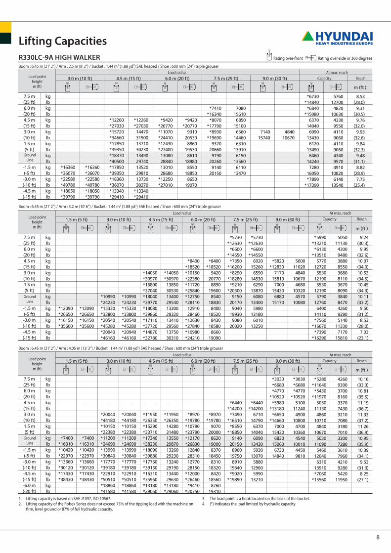
r330nlc-9a
r330lc-9a HigH walkEr
Rating over-front Rating over-side or 360 degrees
Rating over-front Rating over-side or 360 degrees
lifting capacities
Boom : 6.45 m (21’ 2”) / Arm : 3.2 m (10’ 6”) / Bucket : 1.44 m3 (1.88 yd3) sAe heaped / shoe : 600 mm (24”) triple grouser
load pointheightm (ft)
load radius At max. reachCapacity Reach
Groundline
Boom : 6.45 m (21’ 2”) / Arm : 4.05 m (13’ 3”) / Bucket : 1.44 m3 (1.88 yd3) sAe heaped / shoe : 600 mm (24”) triple grouser
load pointheightm (ft)
load radius At max. reachCapacity Reach
Groundline
Boom : 6.45 m (21’ 2”) / Arm : 2.2 m (7’ 3”) / Bucket : 1.44 m3 (1.88 yd3) sAe heaped / shoe : 600 mm (24”) triple grouser
load pointheightm (ft)
load radius At max. reachCapacity Reach
Groundline
8
3.0 m (10 ft) 4.5 m (15 ft) 6.0 m (20 ft) 7.5 m (25 ft) 9.0 m (30 ft)
m (ft )
7.5 m(25 ft)6.0 m(20 ft)4.5 m(15 ft)3.0 m(10 ft)1.5 m(5 ft)
-1.5 m(-5 ft)-3.0 m(-10 ft)-4.5 m(-15 ft)
kglbkglbkglbkglbkglbkglbkglbkglbkglb
*16360*36070*22580*49780*18050*39790
*16360*36070*22580*49780*18050*39790
*12260*27030*15720*34660*17850*39350*18370*40500*17850*39350*16360*36070*13340*29410
*12260*2703014470319001371030230134902974013520298101373030270
*13340*29410
*9420*20770*11070*24410*12430*2740013080288401301028680
*12250*27010
*9420*20770
9310205308860
195308610
189808550
188508650
19070
*7410*16340*8070
*17790*8930
*196909370
206609190
202609140
20150
7080156106850
151006560
144606310
139106150
135606110
13470
714015740
484010670
*6730*14840*6840
*150806370
140406090
134306120
134906460
142407280
16050*7890
*17390
5760127004820
10630433095504110906041109060434095704910
108206140
13540
8.53(28.0)
9.31(30.5)
9.76(32.0)
9.93(32.6)
9.84(32.3)
9.48(31.1)
8.82(28.9)
7.75(25.4)
1.5 m (5 ft) 3.0 m (10 ft) 4.5 m (15 ft) 6.0 m (20 ft) 7.5 m (25 ft) 9.0 m (30 ft)
m (ft )
7.5 m(25 ft)6.0 m(20 ft)4.5 m(15 ft)3.0 m(10 ft)1.5 m(5 ft)
-1.5 m(-5 ft)-3.0 m(-10 ft)-4.5 m(-15 ft)
kglbkglbkglbkglbkglbkglbkglbkglbkglb
*12090*26650*16150*35600
*12090*26650*16150*35600
*10990*24230*15330*33800*20540*45280*20940*46160
*10990*24230*15330*33800*20540*45280*20940*46160
*14050*30970*16800*37040*18040*39770*18080*39860*17110*37720*14870*32780
*14050*3097013850305301340029540133002932013410295601375030310
*8400*18520*10150*22380*11720*25840*12750*281101291028460
*12630*27840*10980*24210
*8400*18520
9420207708890
196008540
188308400
185208430
185808660
19090
*5730*12630*6600
*14550*7350
*16200*8290
*18280*9210
*203009150
201709040
199309080
20020
*5730*12630*6600
*145506920
152606590
145306290
138706080
134005980
131806010
13250
*5820*12830
7170158107000
154306880
15170
5000110204840
106704680
103204570
10080
*5990*13210*6130
*135105770
127205530
121905530
121905790
127606400
14110*7560
*16670*7390
*16290
5050111304300948038808550368081103670809038408470426093905140
113307170
15810
9.24(30.3)
9.95(32.6)10.37(34.0)10.53(34.5)10.45(34.3)10.11(33.2)
9.50(31.2)
8.53(28.0)
7.03(23.1)
1.5 m (5 ft) 3.0 m (10 ft) 4.5 m (15 ft) 6.0 m (20 ft) 7.5 m (25 ft) 9.0 m (30 ft)
m (ft )
7.5 m(25 ft)6.0 m(20 ft)4.5 m(15 ft)3.0 m(10 ft)1.5 m(5 ft)
-1.5 m(-5 ft)-3.0 m(-10 ft)-4.5 m(-15 ft)-6.0 m(-20 ft)
kglbkglbkglbkglbkglbkglbkglbkglbkglbkglb
*7400*16310*10420*22970*13660*30120*17430*38430
*7400*16310*10420*22970*13660*30120*17430*38430
*20040*44180*10150*22380*11200*24690*13990*30840*17770*39180*22910*50510*18860*41580
*20040*44180*10150*22380*11200*24690*13990*30840*17770*39180*22910*50510*18860*41580
*11950*26350*15290*33710*17340*38230*18090*39880*17760*39150*16310*35960*13180*29060
*11950*2635014280314801355029870132602923013240291901344029630
*13180*29060
*8970*19780*10790*23790*12170*2683012840283101277028150
*12000*26460*9410
*20750
*8970*19780
9070200008620
190008370
184508310
183208420
185608760
19310
*6440*14200*7490
*16510*8550
*188509140
201508960
197508910
19640*9020
*19890
*6440*14200
6710147906370
140406090
134305930
130705880
129605990
13210
*3030*6680*4770
*10520*5980
*13180*6650
*146607000
154306830
150606730
14840
*3030*6680*4770
*105205100
112404900
108004700
103604540
1001044509810
*5280*11640*5430
*119705050
111304860
107104840
106705030
110905460
120406310
13910*7060
*15560
42609390370081603370743032107080318070103300728036107960421092805420
11950
10.16(33.3)10.81(35.5)11.19(36.7)11.33(37.2)11.26(36.9)10.95(35.9)10.39(34.1)
9.53(31.3)
8.25(27.1)
r330lc-9a HigH walkEr
lifting capacities
Boom : 6.45 m (21’ 2”) / Arm : 2.5 m (8’ 2”) / Bucket : 1.44 m3 (1.88 yd3) sAe heaped / shoe : 600 mm (24”) triple grouser
load pointheightm (ft)
load radius At max. reachCapacity Reach
Groundline
Boom : 6.45 m (21’ 2”) / Arm : 3.2 m (10’ 6”) / Bucket : 1.44 m3 (1.88 yd3) sAe heaped / shoe : 600 mm (24”) triple grouser
load pointheightm (ft)
load radius At max. reachCapacity Reach
Groundline
Boom : 6.45 m (21’ 2”) / Arm : 4.05 m (13’ 3”) / Bucket : 1.44 m3 (1.88 yd3) sAe heaped / shoe : 600 mm (24”) triple grouser
load pointheightm (ft)
load radius At max. reachCapacity Reach
Groundline
1. lifting capacity is based on sAe J1097, iso 10567.2. lifting capacity of the Robex series does not exceed 75% of the tipping load with the machine on
firm, level ground or 87% of full hydraulic capacity.
3. The load point is a hook located on the back of the bucket.4. (*) indicates the load limited by hydraulic capacity.
Rating over-front Rating over-side or 360 degrees
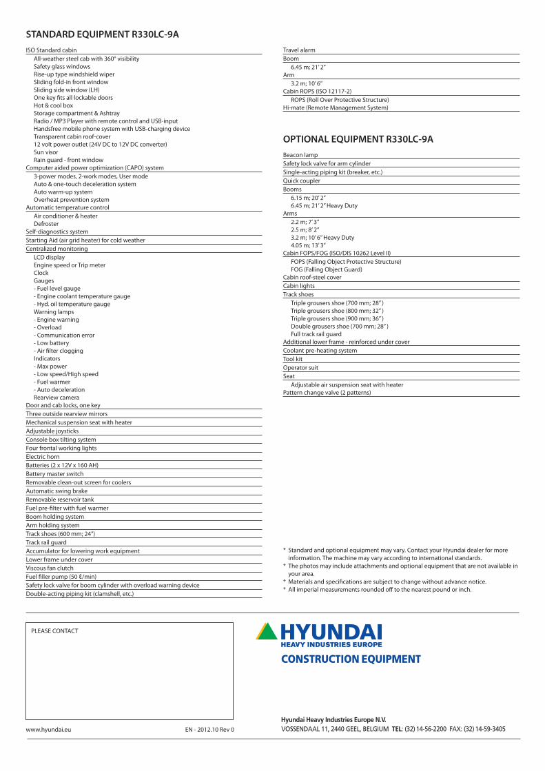
standard EQuipmEnt r330lc-9a
iso standard cabinAll-weather steel cab with 360° visibilitysafety glass windowsRise-up type windshield wipersliding fold-in front windowsliding side window (lH)one key fits all lockable doorsHot & cool boxstorage compartment & AshtrayRadio / MP3 Player with remote control and usB-input Handsfree mobile phone system with usB-charging device Transparent cabin roof-cover12 volt power outlet (24V dC to 12V dC converter)sun visorRain guard - front window
Computer aided power optimization (CAPo) system3-power modes, 2-work modes, user modeAuto & one-touch deceleration systemAuto warm-up systemoverheat prevention system
Automatic temperature controlAir conditioner & heaterdefroster
self-diagnostics systemstarting Aid (air grid heater) for cold weatherCentralized monitoring
lCd displayengine speed or Trip meterClockGauges- fuel level gauge- engine coolant temperature gauge- Hyd. oil temperature gaugeWarning lamps- engine warning- overload- Communication error- low battery- Air filter cloggingindicators- Max power- low speed/High speed- fuel warmer- Auto decelerationRearview camera
door and cab locks, one keyThree outside rearview mirrorsMechanical suspension seat with heaterAdjustable joysticksConsole box tilting systemfour frontal working lightselectric hornBatteries (2 x 12V x 160 AH)Battery master switchRemovable clean-out screen for coolersAutomatic swing brakeRemovable reservoir tankfuel pre-filter with fuel warmerBoom holding systemArm holding systemTrack shoes (600 mm; 24”)Track rail guardAccumulator for lowering work equipmentlower frame under coverViscous fan clutchfuel filler pump (50 ℓ/min)safety lock valve for boom cylinder with overload warning devicedouble-acting piping kit (clamshell, etc.)
Travel alarmBoom
6.45 m; 21’ 2”Arm
3.2 m; 10’ 6”Cabin RoPs (iso 12117-2)
RoPs (Roll over Protective structure)Hi-mate (Remote Management system)
optional EQuipmEnt r330lc-9a
Beacon lampsafety lock valve for arm cylindersingle-acting piping kit (breaker, etc.)Quick couplerBooms
6.15 m; 20’ 2”6.45 m; 21’ 2” Heavy duty
Arms2.2 m; 7’ 3”2.5 m; 8’ 2”3.2 m; 10’ 6” Heavy duty4.05 m; 13’ 3”
Cabin foPs/foG (iso/dis 10262 level ii)foPs (falling object Protective structure)foG (falling object Guard)
Cabin roof-steel coverCabin lightsTrack shoes
Triple grousers shoe (700 mm; 28” )Triple grousers shoe (800 mm; 32” )Triple grousers shoe (900 mm; 36” )double grousers shoe (700 mm; 28” )full track rail guard
Additional lower frame - reinforced under coverCoolant pre-heating systemTool kitoperator suitseat
Adjustable air suspension seat with heaterPattern change valve (2 patterns)
* standard and optional equipment may vary. Contact your Hyundai dealer for more information. The machine may vary according to international standards.
* The photos may include attachments and optional equipment that are not available in your area.
* Materials and specifications are subject to change without advance notice.* All imperial measurements rounded off to the nearest pound or inch.
www.hyundai.eu en - 2012.10 Rev 0
PleAse ConTACT
Related Documents