1 R206A (PICV) Valvola di regolazione indipendente dalla pressione Pressure independent control valve Istruzioni / Instruction 047U58688 10/2021 Giacomini S.p.A. Via per Alzo 39, 28017 San Maurizio d’Opaglio (NO) Italia [email protected] +39 0322 923372 - giacomini.com La valvola di regolazione indipendente dalla pressione R206A (PICV), combina una regolazione automatica della portata ad un controllo della valvola tramite attuatore. La valvola è in grado di regolare la portata e mantenerla costante al variare delle condizioni di pressione differenziale all’interno del circuito idraulico nella quale è installata. La valvola può essere utilizzata con due modalità di funzionamento: • controllo indipendente dalla pressione (con attuatore K281 installato) in conformità con i requisiti di carico termico della sezione del circuito da controllare; • limitazione della portata e/o intercettazione del fluido (senza attuatore o con testa elettrotermica R473 installata). The pressure independent control valve R206A (PICV), combines an automatic control of the flow rate with a control of the valve throught an actuator. The valve is able to regulate the flow rate and keep it constant as the differential pressure conditions vary within the hydraulic circuit in which it is installed. The valve can be used with two operating modes: • independent control of the pressure (with K281 actuator installed) in accordance with the thermal load requirements of the circuit section to be controlled; • limitation of the flow rate and/or shut-off of the fluid (without actuator or with R473 thermo-electric actuator installed). Dimensioni Dimensions CODICE PRODUCT CODE DN A [mm] B [mm] C [mm] D [mm] E [mm] F [mm] G [mm] H [mm] I [mm] L [mm] M [mm] N [mm] O [mm] P [mm] Q [mm] R [mm] R206AY113 15 G 1/2”M 128 64 99 45 54 49 20 29 ch.30 22 25 101 54 103 49 R206AY103 15 G 1/2”M 128 64 99 45 54 49 20 29 ch.30 22 25 101 54 103 49 R206AY104 20 G 3/4”M 136 68 99 45 54 49 20 29 ch.38 22 25 101 54 103 49 R206AY105 20 G 1”M 142 71 99 45 54 49 20 29 ch.38 22 25 101 54 103 49 R206AY125 25 G 1”M 162 81 111 52 59 65 30 35 ch.53 27 31 123 65 112 65 R206AY106 25 G 1-1/4”M 165 83 111 52 59 65 30 35 ch.53 27 31 123 65 n.d. 65 R206A O Q P R R206A + K281X062 R206A + R473 A A E F D B G C C H I L L M N Accessori • R473X221: testa elettrotermica 230 V, normalmente chiusa, tipo ON/OFF • R473X222: testa elettrotermica 24 V, normalmente chiusa, tipo ON/OFF • K281X062: attuatore 24 V per controllo lineare proporzionale della portata (0-10 V) • R453FY002: ghiera adattatore M30 x 1,5 mm per teste elettrotermiche R473 • R225EY001: manometro di pressione differenziale con sonde • P206Y001: coppia di prese di pressione • P206Y011: coppia di prese di pressione con raccordo orientabile Ricambi • R73PY010: chiave per la preregolazione della portata Accessories • R473X221: thermo-electric actuator 230 V, normally closed, ON/OFF type • R473X222: thermo-electric actuator 24 V, normally closed, ON/OFF type • K281X062: actuator 24 V for proportional linear flow rate control (0-10 V) • R453FY002: adapter ring M30 x 1,5 mm for R473 thermo-electric actuator • R225EY001: differential pressure gauge with probe • P206Y001: pair of pressure outlets • P206Y011: pair of pressure outlets with adjustable fitting Spare parts • R73PY010: regulation key for the presetting of the flow rate Versioni e codici Versions and product codes CODICE PRODUCT CODE DN CORPO VALVOLA VALVE BODY SIZE ATTACCHI CONNECTIONS COLORE INDICATORE INDICATOR COLOUR COLORE VOLANTINO HANDWHEEL COLOUR CAMPO DI REGOLAZIONE DELLA PORTATA WORKING FLOW RATE RANGE [l/h] CAMPO DI PRESSIONE DIFFERENZIALE DI FUNZIONAMENTO WORKING DIFFERENTIAL PRESSURE RANGE [kPa] L (LOW) H (HIGH) CON TESTA ELETT. R473 WITH R473 ACTUATORS CON ATTUATORE K281 O SENZA WITH K281 ACTUATOR OR WITHOUT R206AY113 15 G 1/2”M a bocchettoni with tail pieces ROSSO RED GRIGIO GREY 35÷520 l/h 25÷400 kPa 25÷800 kPa R206AY103 15 G 1/2”M a bocchettoni with tail pieces BLU BLUE ROSSO RED 150÷380 l/h 180÷630 l/h 25÷400 kPa 25÷800 kPa R206AY104 20 G 3/4”M a bocchettoni with tail pieces NERO BLACK ROSSO RED 320÷910 l/h 700÷1175 l/h 25÷400 kPa 25÷800 kPa R206AY105 20 G 1”M a bocchettoni with tail pieces VERDE GREEN BLU BLUE 290÷1000 l/h 860÷1500 l/h 25÷400 kPa 25÷800 kPa R206AY125 25 G 1”M a bocchettoni with tail pieces BLU BLUE ROSSO RED 400÷3800 l/h 25÷400 kPa 25÷400 kPa R206AY106 25 G 1-1/4”M a bocchettoni with tail pieces NERO BLACK BLU BLUE 400÷4700 l/h U/A 25÷400 kPa

Welcome message from author
This document is posted to help you gain knowledge. Please leave a comment to let me know what you think about it! Share it to your friends and learn new things together.
Transcript
1
R206A (PICV)Valvola di regolazione indipendente dalla pressionePressure independent control valve
Istruzioni / Instruction047U58688 10/2021
Giacomini S.p.A.
Via per Alzo 39, 28017 San Maurizio d’Opaglio (NO) Italia
+39 0322 923372 - giacomini.com
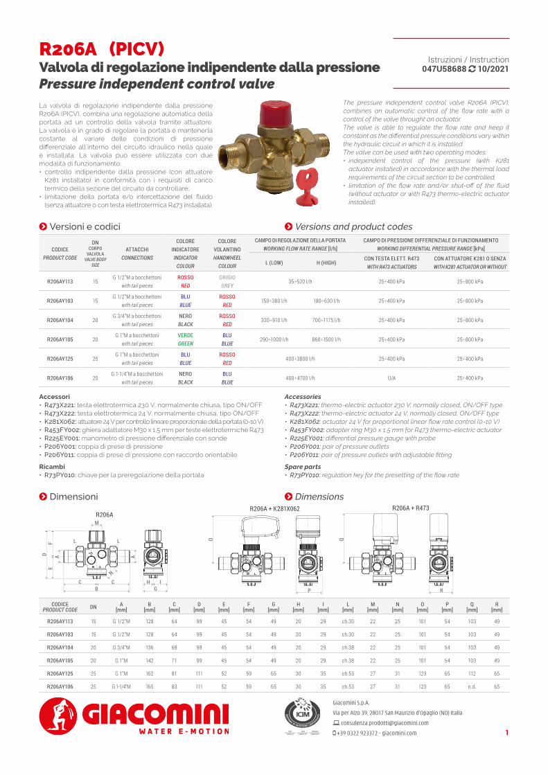
La valvola di regolazione indipendente dalla pressione R206A (PICV), combina una regolazione automatica della portata ad un controllo della valvola tramite attuatore. La valvola è in grado di regolare la portata e mantenerla costante al variare delle condizioni di pressione differenziale all’interno del circuito idraulico nella quale è installata. La valvola può essere utilizzata con due modalità di funzionamento:• controllo indipendente dalla pressione (con attuatore
K281 installato) in conformità con i requisiti di carico termico della sezione del circuito da controllare;
• limitazione della portata e/o intercettazione del fluido (senza attuatore o con testa elettrotermica R473 installata).
The pressure independent control valve R206A (PICV), combines an automatic control of the flow rate with a control of the valve throught an actuator.The valve is able to regulate the flow rate and keep it constant as the differential pressure conditions vary within the hydraulic circuit in which it is installed.The valve can be used with two operating modes:• independent control of the pressure (with K281
actuator installed) in accordance with the thermal load requirements of the circuit section to be controlled;
• limitation of the flow rate and/or shut-off of the fluid (without actuator or with R473 thermo-electric actuator installed).
Dimensioni Dimensions
CODICEPRODUCT CODE DN A
[mm]B
[mm]C
[mm]D
[mm]E
[mm]F
[mm]G
[mm]H
[mm]I
[mm]L
[mm]M
[mm]N
[mm]O
[mm]P
[mm]Q
[mm]R
[mm]
R206AY113 15 G 1/2”M 128 64 99 45 54 49 20 29 ch.30 22 25 101 54 103 49
R206AY103 15 G 1/2”M 128 64 99 45 54 49 20 29 ch.30 22 25 101 54 103 49
R206AY104 20 G 3/4”M 136 68 99 45 54 49 20 29 ch.38 22 25 101 54 103 49
R206AY105 20 G 1”M 142 71 99 45 54 49 20 29 ch.38 22 25 101 54 103 49
R206AY125 25 G 1”M 162 81 111 52 59 65 30 35 ch.53 27 31 123 65 112 65
R206AY106 25 G 1-1/4”M 165 83 111 52 59 65 30 35 ch.53 27 31 123 65 n.d. 65
R206A
AAE
FD
O Q
B GP RC C H I
L L
M
N
R206A + K281X062 R206A + R473
AAE
FD
O Q
B GP RC C H I
L L
M
N
Accessori• R473X221: testa elettrotermica 230 V, normalmente chiusa, tipo ON/OFF• R473X222: testa elettrotermica 24 V, normalmente chiusa, tipo ON/OFF• K281X062: attuatore 24 V per controllo lineare proporzionale della portata (0-10 V)• R453FY002: ghiera adattatore M30 x 1,5 mm per teste elettrotermiche R473• R225EY001: manometro di pressione differenziale con sonde• P206Y001: coppia di prese di pressione• P206Y011: coppia di prese di pressione con raccordo orientabile
Ricambi• R73PY010: chiave per la preregolazione della portata
Accessories• R473X221: thermo-electric actuator 230 V, normally closed, ON/OFF type• R473X222: thermo-electric actuator 24 V, normally closed, ON/OFF type• K281X062: actuator 24 V for proportional linear flow rate control (0-10 V)• R453FY002: adapter ring M30 x 1,5 mm for R473 thermo-electric actuator• R225EY001: differential pressure gauge with probe• P206Y001: pair of pressure outlets• P206Y011: pair of pressure outlets with adjustable fitting
Spare parts• R73PY010: regulation key for the presetting of the flow rate
Versioni e codici Versions and product codes
CODICEPRODUCT CODE
DNCORPO
VALVOLAVALVE BODY
SIZE
ATTACCHICONNECTIONS
COLOREINDICATOREINDICATOR
COLOUR
COLOREVOLANTINOHANDWHEEL
COLOUR
CAMPO DI REGOLAZIONE DELLA PORTATAWORKING FLOW RATE RANGE [l/h]
CAMPO DI PRESSIONE DIFFERENZIALE DI FUNZIONAMENTOWORKING DIFFERENTIAL PRESSURE RANGE [kPa]
L (LOW) H (HIGH)CON TESTA ELETT. R473
WITH R473 ACTUATORSCON ATTUATORE K281 O SENZAWITH K281 ACTUATOR OR WITHOUT
R206AY113 15G 1/2”M a bocchettoni
with tail piecesROSSO
REDGRIGIOGREY
35÷520 l/h 25÷400 kPa 25÷800 kPa
R206AY103 15G 1/2”M a bocchettoni
with tail piecesBLU
BLUEROSSO
RED150÷380 l/h 180÷630 l/h 25÷400 kPa 25÷800 kPa
R206AY104 20G 3/4”M a bocchettoni
with tail piecesNEROBLACK
ROSSORED
320÷910 l/h 700÷1175 l/h 25÷400 kPa 25÷800 kPa
R206AY105 20G 1”M a bocchettoni
with tail piecesVERDEGREEN
BLUBLUE
290÷1000 l/h 860÷1500 l/h 25÷400 kPa 25÷800 kPa
R206AY125 25G 1”M a bocchettoni
with tail piecesBLU
BLUEROSSO
RED400÷3800 l/h 25÷400 kPa 25÷400 kPa
R206AY106 25G 1-1/4”M a bocchettoni
with tail piecesNEROBLACK
BLUBLUE
400÷4700 l/h U/A 25÷400 kPa
2
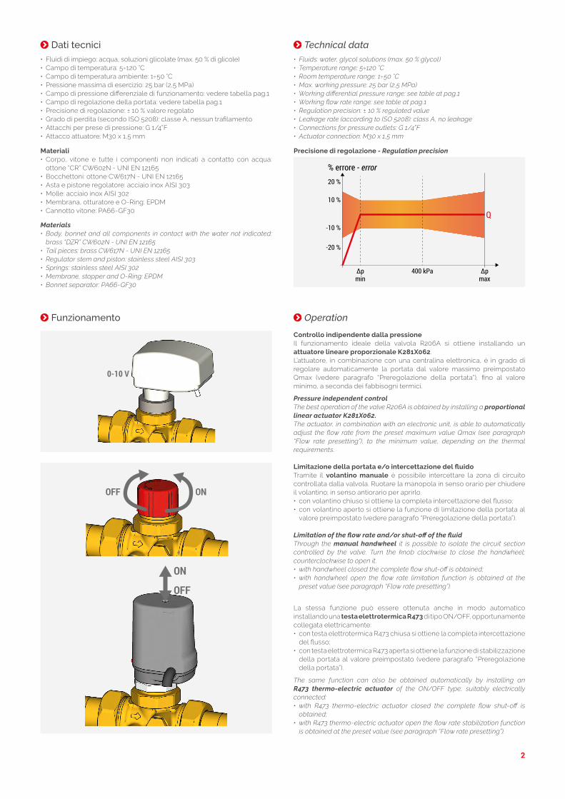
Dati tecnici• Fluidi di impiego: acqua, soluzioni glicolate (max. 50 % di glicole)• Campo di temperatura: 5÷120 °C• Campo di temperatura ambiente: 1÷50 °C• Pressione massima di esercizio: 25 bar (2,5 MPa)• Campo di pressione differenziale di funzionamento: vedere tabella pag.1• Campo di regolazione della portata: vedere tabella pag.1• Precisione di regolazione: ± 10 % valore regolato• Grado di perdita (secondo ISO 5208): classe A, nessun trafilamento• Attacchi per prese di pressione: G 1/4”F• Attacco attuatore: M30 x 1,5 mm
Technical data
Materiali• Corpo, vitone e tutte i componenti non indicati a contatto con acqua:
ottone “CR” CW602N - UNI EN 12165• Bocchettoni: ottone CW617N - UNI EN 12165• Asta e pistone regolatore: acciaio inox AISI 303• Molle: acciaio inox AISI 302• Membrana, otturatore e O-Ring: EPDM• Cannotto vitone: PA66-GF30
Materials• Body, bonnet and all components in contact with the water not indicated:
brass “DZR” CW602N - UNI EN 12165• Tail pieces: brass CW617N - UNI EN 12165• Regulator stem and piston: stainless steel AISI 303• Springs: stainless steel AISI 302• Membrane, stopper and O-Ring: EPDM• Bonnet separator: PA66-GF30
• Fluids: water, glycol solutions (max. 50 % glycol)• Temperature range: 5÷120 °C• Room temperature range: 1÷50 °C• Max. working pressure: 25 bar (2,5 MPa)• Working differential pressure range: see table at pag.1• Working flow rate range: see table at pag.1• Regulation precision: ± 10 % regulated value• Leakage rate (according to ISO 5208): class A, no leakage• Connections for pressure outlets: G 1/4”F• Actuator connection: M30 x 1,5 mm
Precisione di regolazione - Regulation precision
∆pmax
∆pmin
% errore - error
-20 %
-10 %
10 %
20 %
400 kPa
Q
Funzionamento Operation
Controllo indipendente dalla pressioneIl funzionamento ideale della valvola R206A si ottiene installando un attuatore lineare proporzionale K281X062.L’attuatore, in combinazione con una centralina elettronica, è in grado di regolare automaticamente la portata dal valore massimo preimpostato Qmax (vedere paragrafo “Preregolazione della portata”), fino al valore minimo, a seconda dei fabbisogni termici.
Pressure independent controlThe best operation of the valve R206A is obtained by installing a proportional linear actuator K281X062.The actuator, in combination with an electronic unit, is able to automatically adjust the flow rate from the preset maximum value Qmax (see paragraph “Flow rate presetting”), to the minimum value, depending on the thermal requirements.
0-10 V
Limitazione della portata e/o intercettazione del fluidoTramite il volantino manuale è possibile intercettare la zona di circuito controllata dalla valvola. Ruotare la manopola in senso orario per chiudere il volantino; in senso antiorario per aprirlo.• con volantino chiuso si ottiene la completa intercettazione del flusso;• con volantino aperto si ottiene la funzione di limitazione della portata al
valore preimpostato (vedere paragrafo “Preregolazione della portata”).
Limitation of the flow rate and/or shut-off of the fluidThrough the manual handwheel it is possible to isolate the circuit section controlled by the valve. Turn the knob clockwise to close the handwheel; counterclockwise to open it.• with handwheel closed the complete flow shut-off is obtained;• with handwheel open the flow rate limitation function is obtained at the
preset value (see paragraph “Flow rate presetting”).
OFF ON
La stessa funzione può essere ottenuta anche in modo automatico installando una testa elettrotermica R473 di tipo ON/OFF, opportunamente collegata elettricamente:• con testa elettrotermica R473 chiusa si ottiene la completa intercettazione
del flusso;• con testa elettrotermica R473 aperta si ottiene la funzione di stabilizzazione
della portata al valore preimpostato (vedere paragrafo “Preregolazione della portata”).
The same function can also be obtained automatically by installing an R473 thermo-electric actuator of the ON/OFF type, suitably electrically connected:• with R473 thermo-electric actuator closed the complete flow shut-off is
obtained;• with R473 thermo-electric actuator open the flow rate stabilization function
is obtained at the preset value (see paragraph “Flow rate presetting”).
ON
OFF
3
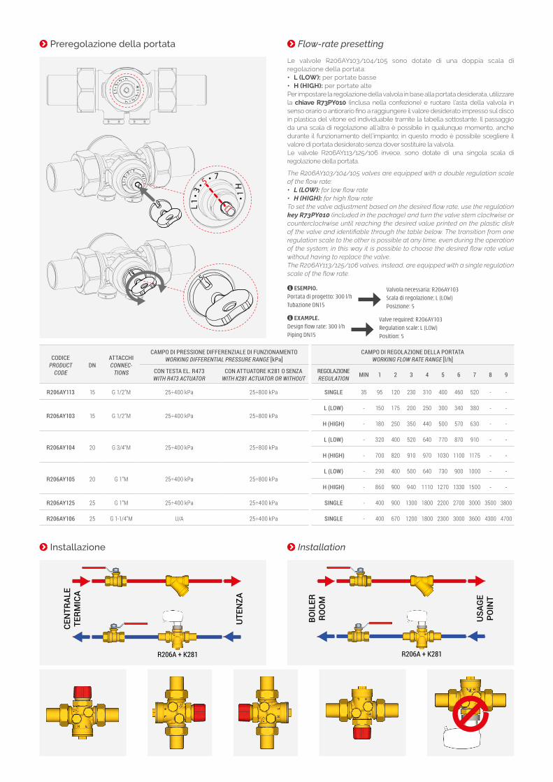
Installazione Installation
R206A + K281
UTE
NZA
CEN
TRAL
E TE
RMIC
A
R206A + K281
USA
GE
POIN
T
BOIL
ERRO
OM
ESEMPIO.Portata di progetto: 300 l/h
Tubazione DN15
Valvola necessaria: R206AY103
Scala di regolazione: L (LOW)
Posizione: 5
EXAMPLE.Design flow rate: 300 l/h
Piping DN15
Valve required: R206AY103
Regulation scale: L (LOW)
Position: 5
Preregolazione della portata
Le valvole R206AY103/104/105 sono dotate di una doppia scala di regolazione della portata:• L (LOW): per portate basse• H (HIGH): per portate altePer impostare la regolazione della valvola in base alla portata desiderata, utilizzare la chiave R73PY010 (inclusa nella confezione) e ruotare l’asta della valvola in senso orario o antiorario fino a raggiungere il valore desiderato impresso sul disco in plastica del vitone ed individuabile tramite la tabella sottostante. Il passaggio da una scala di regolazione all’altra è possibile in qualunque momento, anche durante il funzionamento dell’impianto; in questo modo è possibile scegliere il valore di portata desiderato senza dover sostituire la valvola.Le valvole R206AY113/125/106 invece, sono dotate di una singola scala di regolazione della portata.
The R206AY103/104/105 valves are equipped with a double regulation scale of the flow rate:• L (LOW): for low flow rate• H (HIGH): for high flow rateTo set the valve adjustment based on the desired flow rate, use the regulation key R73PY010 (included in the package) and turn the valve stem clockwise or counterclockwise until reaching the desired value printed on the plastic disk of the valve and identifiable through the table below. The transition from one regulation scale to the other is possible at any time, even during the operation of the system; in this way it is possible to choose the desired flow rate value without having to replace the valve.The R206AY113/125/106 valves, instead, are equipped with a single regulation scale of the flow rate.
L1
3
57
••
•
H1•
5
L1
35
7
••
•
H1•
5
L1 1
• 3• 5• 7
7
H•
• 35•L1
3
57
••
•
H1•
5
L1
35
7•
••
H1•
5
L1 1
• 3• 5• 7
7
H•
• 35•L1
3
57
••
•
H1•
5
L1
3
57
••
•
H1•
5
L1 1
• 3• 5• 7
7
H•
• 35•
Flow-rate presetting
CODICEPRODUCT
CODEDN
ATTACCHICONNEC-
TIONS
CAMPO DI PRESSIONE DIFFERENZIALE DI FUNZIONAMENTOWORKING DIFFERENTIAL PRESSURE RANGE [kPa]
CAMPO DI REGOLAZIONE DELLA PORTATAWORKING FLOW RATE RANGE [l/h]
CON TESTA EL. R473WITH R473 ACTUATOR
CON ATTUATORE K281 O SENZAWITH K281 ACTUATOR OR WITHOUT
REGOLAZIONEREGULATION MIN 1 2 3 4 5 6 7 8 9
R206AY113 15 G 1/2”M 25÷400 kPa 25÷800 kPa SINGLE 35 95 120 230 310 400 460 520 - -
R206AY103 15 G 1/2”M 25÷400 kPa 25÷800 kPaL (LOW) - 150 175 200 250 300 340 380 - -
H (HIGH) - 180 250 350 440 500 570 630 - -
R206AY104 20 G 3/4”M 25÷400 kPa 25÷800 kPaL (LOW) - 320 400 520 640 770 870 910 - -
H (HIGH) - 700 820 910 970 1030 1100 1175 - -
R206AY105 20 G 1”M 25÷400 kPa 25÷800 kPaL (LOW) - 290 400 500 640 730 900 1000 - -
H (HIGH) - 860 900 940 1110 1270 1330 1500 - -
R206AY125 25 G 1”M 25÷400 kPa 25÷400 kPa SINGLE - 400 900 1300 1800 2200 2700 3000 3500 3800
R206AY106 25 G 1-1/4”M U/A 25÷400 kPa SINGLE - 400 670 1200 1800 2300 3000 3600 4300 4700

4
Installazione teste elettrotermiche R473X221 o R473X222
R453FY002 R473
PUSH
15°
2R453FY002 R473
PUSH
15°
3R453FY002 R473
PUSH
15°
41R453FY002 R473
PUSH
15°
Installation of R473X221 or R473X222 thermo-electric actuators
Installazione attuatore K281X062
1
K281
M30 x 1,5 mm
2
K281
M30 x 1,5 mm
Installation of actuator K281X062
Installazione delle prese di pressione P206 e verifica della portata tramite manometro di pressione differenziale R225EY001La valvola è dotata di attacchi per prese di pressione P206 da installare con impianto spento e non in pressione. Tramite il manometro di pressione differenziale R225EY001 e le proprie sonde opportunamente alloggiate nelle prese di pressione è possibile misurare il Δp della valvola (P1-P3) durante il normale funzionamento.
1
4 mm P206
+ � H - � LR225E
P1P3
2
4 mm P206
+ � H - � LR225E
P1P3
3
4 mm P206
+ � H - � LR225E
P1P3
4
4 mm P206
+ � H - � LR225E
P1P3
AVVERTENZE. Possono verificarsi trafilamenti di acqua attraverso le prese di pressione durante
l’inserimento delle sonde. Indossare indumenti e occhiali protettivi per prevenire danni fisici personali
durante la misura della pressione. Non usare lubrificanti sulle sonde per agevolare l’inserimento nelle
prese. Se necessario bagnare semplicementi le sonde con acqua pulita.
Non lasciare le sonde nella presa di pressione troppo a lungo, poichè ciò potrebbe produrre delle perdite.
Installation of the P206 pressure outlets and flow rate verification through the R225EY001 differential pressure gaugeThe valve is equipped with connections for the P206 pressure outlets to be installed with the system switched off and not under pressure. Using the R225EY001 differential pressure gauge and its probes suitably housed in the pressure outlets, it is possible to measure the Δp of the valve (P1-P3) during normal operation.
WARNINGS. Water leakage may occur through the pressure outlets during the insertion of the probes.
Wear protective clothing and goggles to prevent personal injury during pressure measurement.
Do not use lubricants on the probes to facilitate insertion into the outlets. If necessary, wet the probes
with clean water.
Do not leave the probes in the pressure outlet longer than necessary, as this could cause leakage.
Avvertenze per la sicurezza. L’installazione, la messa in servizio e la periodica manutenzione del prodotto devono
essere eseguite da personale professionalmente abilitato, in accordo con i regolamenti nazionali e/o i requisiti locali.
L’installatore qualificato deve adottare tutti gli accorgimenti necessari, incluso l’utilizzo di Dispositivi di Protezione
Individuale, per assicurare la propria incolumità e quella di terzi. L’errata installazione può causare danni a persone,
animali o cose nei confronti dei quali Giacomini S.p.A. non può essere considerata responsabile.
Safety Warning. Installation, commissioning and periodical maintenance of the product must be carried out
by qualified operators in compliance with national regulations and/or local standards. A qualified installer must
take all required measures, including use of Individual Protection Devices, for his and others’ safety. An improper
installation may damage people, animals or objects towards which Giacomini S.p.A. may not be held liable.
Smaltimento imballo. Scatole in cartone: raccolta differenziata carta. Sacchetti in plastica e pluriball: raccolta
differenziata plastica.
Package Disposal. Carton boxes: paper recycling. Plastic bags and bubble wrap: plastic recycling.
Smaltimento del prodotto. Alla fine del suo ciclo di vita il prodotto non deve essere smaltito come rifiuto
urbano. Può essere portato ad un centro speciale di riciclaggio gestito dall’autorità locale o ad un rivenditore
che offre questo servizio.
Product Disposal. Do not dispose of product as municipal waste at the end of its life cycle. Dispose of product at
a special recycling platform managed by local authorities or at retailers providing this type of service.
Altre informazioni. Per ulteriori informazioni consultare il sito giacomini.com o contattare il servizio
tecnico. Questa comunicazione ha valore indicativo. Giacomini S.p.A. si riserva il diritto di apportare in qualunque
momento, senza preavviso, modifiche per ragioni tecniche o commerciali agli articoli contenuti nella presente
comunicazione. Le informazioni contenute in questa comunicazione tecnica non esentano l’utilizzatore dal
seguire scrupolosamente le normative e le norme di buona tecnica esistenti.
Additional information. For more information, go to giacomini.com or contact our technical assistance
service. This document provides only general indications. Giacomini S.p.A. may change at any time, without
notice and for technical or commercial reasons, the items included herewith. The information included in this
technical sheet do not exempt the user from strictly complying with the rules and good practice standards in
force.
Related Documents