OPERATION/MAINTENANCE MANUAL & PARTS LIST TWO STAGE/TWO CYLINDER AIR COMPRESSORS & UNITS FEATURING THE R10 & R15 PUMPS THIS MANUAL CONTAINS IMPORTANT SAFETY INFORMATION AND SHOULD ALWAYS BE AVAILABLE TO THOSE PERSONNEL OPERATING THIS UNIT. READ, UNDERSTAND AND RETAIN ALL INSTRUCTIONS BEFORE OPERATING THIS EQUIPMENT TO PREVENT INJURY OR EQUIPMENT DAMAGE. MODEL R15B COMPRESSOR MODEL HR2-6 UNIT Form No. F3231 Ver: 02 01/08/2004 C453-A (Ref. Drawing) C452-A (Ref. Drawing)

Welcome message from author
This document is posted to help you gain knowledge. Please leave a comment to let me know what you think about it! Share it to your friends and learn new things together.
Transcript

OPERATION/MAINTENANCE MANUAL & PARTS LIST
TWO STAGE/TWO CYLINDER AIR COMPRESSORS & UNITS FEATURING THE R10 & R15 PUMPS
THIS MANUAL CONTAINS IMPORTANT SAFETY INFORMATION AND SHOULD
ALWAYS BE AVAILABLE TO THOSE PERSONNEL OPERATING THIS UNIT. READ, UNDERSTAND AND RETAIN ALL INSTRUCTIONS BEFORE OPERATING THIS
EQUIPMENT TO PREVENT INJURY OR EQUIPMENT DAMAGE. MODEL R15B COMPRESSOR MODEL HR2-6 UNIT
Form No. F3231 Ver: 02 01/08/2004
C453-A (Ref. Drawing) C452-A
(Ref. Drawing)
2
MAINTAIN COMPRESSOR RELIABILITY AND PERFORMANCE WITH GENUINE CHAMPION COMPRESSOR
PARTS AND SUPPORT SERVICES
Champion Compressor genuine parts, manufactured to design tolerances, are developed for optimum dependability – specifically for Champion compressor systems. Design and material innovations are the result of years of experience with hundreds of different compressor applications. Reliability in materials and quality assurance are incorporated in our genuine replacement parts. Your authorized Champion Compressor distributor offers all the backup you’ll need. A worldwide network of authorized distributors provides the finest product support in the air compressor industry. Your authorized distributor can support your Champion air compressor with these services: 1. Trained parts specialists to assist you in selecting the correct replacement parts.
2. A full line of factory tested CHAMPLUB™ compressor lubricants specifically formulated for use in Champion compressors.
3. Repair and maintenance kits designed with the necessary parts to simplify servicing your compressor.
Authorized distributor service technicians are factory trained and skilled in compressor maintenance and repair. They are ready to respond and assist you by providing fast, expert maintenance and repair services. For the location of your local authorized Champion Air Compressor distributor, refer to the yellow pages of your phone directory or contact:
INSTRUCTIONS FOR ORDERING REPAIR PARTS When ordering parts, specify Compressor MODEL, HORSEPOWER and SERIAL NUMBER (see nameplate on unit). All orders for Parts should be placed with the nearest authorized distributor. Order by part number and description. Reference numbers are for your convenience only.
Factory: Champion 1301 North Euclid Avenue Princeton, IL 61356 Phone: (815) 875-3321 Fax: (815) 872-0421 E-Mail: Champion@Championpneumatic . com
3
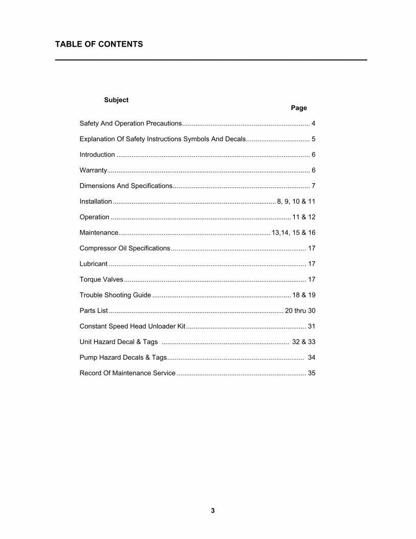
TABLE OF CONTENTS _______________________________________________________
Subject Page
Safety And Operation Precautions.................................................................... 4
Explanation Of Safety Instructions Symbols And Decals.................................. 5
Introduction ....................................................................................................... 6
Warranty............................................................................................................ 6
Dimensions And Specifications......................................................................... 7
Installation....................................................................................... 8, 9, 10 & 11
Operation ................................................................................................ 11 & 12
Maintenance................................................................................. 13,14, 15 & 16
Compressor Oil Specifications........................................................................ 17
Lubricant ......................................................................................................... 17
Torque Valves................................................................................................. 17
Trouble Shooting Guide .......................................................................... 18 & 19
Parts List ............................................................................................. 20 thru 30
Constant Speed Head Unloader Kit ................................................................ 31
Unit Hazard Decal & Tags .................................................................... 32 & 33
Pump Hazard Decals & Tags......................................................................... 34
Record Of Maintenance Service ..................................................................... 35
4
SAFETY AND OPERATION PRECAUTIONS _______________________________________________________________________________________ Because an air compressor is a piece of machinery with moving and rotating parts, the same precautions should be observed as with any piece of machinery of this type where carelessness in operation or maintenance is hazardous to personnel. In addition to the many obvious safety rules that should be followed with this type of machinery, the additional safety precautions as listed below must be observed: 1. Read all instructions completely before operating air compressor or unit. 2. For installation, follow all local electrical and safety codes, as well as the National Electrical Code (NEC) and the
Occupational Safety and Health Act (OSHA). 3. Electric motors must be securely and adequately grounded. This can be accomplished by wiring with a grounded,
metal-clad raceway system to the starter; by using a separate ground wire connected to the bare metal of the motor frame; or other suitable means.
4. Protect the power cable from coming in contact with sharp objects. Do not kink power cable and never allow the cable to come in contact with oil, grease, hot surfaces, or chemicals.
5. Make certain that the power source conforms to the requirements of your equipment. 6. Pull main electrical disconnect switch and disconnect any separate control lines, if used, before attempting to work
or perform maintenance on the air compressor or unit. "Lock out" or "Tag out" all power sources. 7. Do not attempt to remove any compressor parts without first relieving the entire system of pressure. 8. Do not attempt to service any part while machine is in an operational mode. 9. Do not operate the compressor at pressures in excess of its rating. 10. Do not operate compressor at speeds in excess of its rating. 11. Periodically check all safety devices for proper operation. Do not change pressure setting or restrict operation in
any way. 12. Be sure no tools, or rags or loose parts are left on the compressor or drive parts. 13. Do not use flammable solvents for cleaning the air inlet filter or element and other parts. 14. Exercise cleanliness during maintenance and when making repairs. Keep dirt away from parts by covering parts
and exposed openings with clean cloth or Kraft paper. 15. Do not operate the compressor without guards, shields and screens in place. 16. Do not install a shut-off valve in the discharge line, unless a pressure relief valve, of proper design and size, is
installed in the line between the compressor unit and shut-off valve. 17. Do not operate compressor in areas where there is a possibility of ingesting flammable or toxic fumes. 18. Be careful when touching the exterior of a recently run motor - it may be hot enough to be painful or cause injury.
With modern motors this condition is normal if operated at rated load - modern motors are built to operate at higher temperatures.
19. Inspect unit daily to observe and correct any unsafe operating conditions found. 20. Do not "play around" with compressed air, nor direct air stream at body, because this can cause injuries. 21. Compressed air from this machine absolutely must not be used for food processing or breathing air without
adequate downstream filters, purifiers and controls. 22. Always use an air pressure regulating device at the point of use, and do not use air pressure greater than marked
maximum pressure of attachment. 23. Check hoses for weak or worn condition before each use and make certain that all connections are secure. 24. Always wear safety glasses when using compressed air gun. The user of any air compressor package manufactured by Champion – A Gardner Denver Co., is hereby warned that failure to follow the preceding Safety and Operation Precautions can result in injuries or equipment damage. However, Champion – A Gardner Denver Co., does not state as fact or does not mean to imply that the preceding list of Safety and Operating Precautions is all inclusive, and further that the observance of this list will prevent all injuries or equipment damage.
5
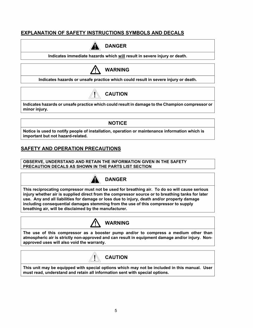
EXPLANATION OF SAFETY INSTRUCTIONS SYMBOLS AND DECALS
DANGER
Indicates immediate hazards which will result in severe injury or death.
WARNING
Indicates hazards or unsafe practice which could result in severe injury or death.
CAUTION
Indicates hazards or unsafe practice which could result in damage to the Champion compressor or minor injury.
NOTICE
Notice is used to notify people of installation, operation or maintenance information which is important but not hazard-related.
SAFETY AND OPERATION PRECAUTIONS OBSERVE, UNDERSTAND AND RETAIN THE INFORMATION GIVEN IN THE SAFETY PRECAUTION DECALS AS SHOWN IN THE PARTS LIST SECTION
DANGER
This reciprocating compressor must not be used for breathing air. To do so will cause serious injury whether air is supplied direct from the compressor source or to breathing tanks for later use. Any and all liabilities for damage or loss due to injury, death and/or property damage including consequential damages stemming from the use of this compressor to supply breathing air, will be disclaimed by the manufacturer.
WARNING
The use of this compressor as a booster pump and/or to compress a medium other than atmospheric air is strictly non-approved and can result in equipment damage and/or injury. Non-approved uses will also void the warranty.
CAUTION
This unit may be equipped with special options which may not be included in this manual. User must read, understand and retain all information sent with special options.
6
INTRODUCTION ____________________________________________________________________
Champion R Series compressor are the result of advanced engineering and skilled manufacturing. To be
assured of receiving maximum service from this machine the owner must exercise care in its operation and maintenance. This book is written to give the operator and maintenance department essential information for day-to-day operation, maintenance and adjustment. Careful adherence to these instructions will result in economical operation and minimum downtime.
Champion Five Year Warranty "R" Series Compressors CHAMPION warrants each new compressor pump manufactured by CHAMPION, mounted on a factory assembled unit, to be free from defects in material and workmanship under normal use and service for a period of sixty (60) months from date of installation or sixty-six (66) months from date of shipment by CHAMPION or CHAMPION distributor, whichever may occur first. Applies to the compressor pump only, excluding head valves. Valves, controls and accessories are warranted for the first year only. Compressor pumps purchased separately would carry a one year warranty. This five year extended warranty will be prorated over the 5 years as follows:
First Year - 100% Allowance, Parts and Labor Second Year - 90% Allowance, Parts and Labor Third Year - 80% Allowance, Parts and Labor Fourth Year - 70% Allowance, Parts and Labor Fifth Year - 60% Allowance, Parts and Labor
Applies to CHAMPION logo, tank or base mounted complete compressors only.
Express Limited Warranty CHAMPION warrants each new air compressor unit manufactured by CHAMPION to be free from defects in material and workmanship under normal use and service for a period of twelve (12) months from date of installation or eighteen (18) months from date of shipment by CHAMPION or CHAMPION distributor, whichever may occur first. CHAMPION makes no warranty in respect to components and accessories furnished to CHAMPION by third parties, such as ELECTRIC MOTORS, GASOLINE ENGINES and CONTROLS, which are warranted only to the extent of the original manufacturer's warranty to CHAMPION. To have warranty consideration, electric motors must be equipped with thermal overload protection. The extended five year warranty will apply to ASME air receivers provided they are installed on rubber vibro isolator pads. When a compressor pump, or component is changed or replaced during the warranty period, the new/replaced item is warranted for only the remainder of the original warranty period. Repair, replacement or refund in the manner and within the time provided shall constitute CHAMPION'S sole liability and your exclusive remedy resulting from any nonconformity or defect. CHAMPION SHALL NOT IN ANY EVENT BE LIABLE FOR ANY DAMAGES, WHETHER BASED ON CONTRACT, WARRANTY, NEGLIGENCE, STRICT LIABILITY OR OTHERWISE, INCLUDING WITHOUT LIMITATION ANY CONSEQUENTIAL, INCIDENTAL OR SPECIAL DAMAGES, ARISING WITH RESPECT TO THE EQUIPMENT OR ITS FAILURE TO OPERATE, EVEN IF CHAMPION HAS BEEN ADVISED OF THE POSSIBILITY THEREOF. CHAMPION MAKES NO OTHER WARRANTY OR REPRESENTATION OF ANY KIND, EXCEPT THAT OF TITLE, AND ALL OTHER WARRANTIES, EXPRESS OR IMPLIED, INCLUDING WARRANTIES OR MERCHANTABILITY AND FITNESS FOR A PARTICULAR PURPOSE, ARE HEREBY EXPRESSLY DISCLAIMED. NO SALESMAN OR OTHER REPRESENTATIVE OF CHAMPION HAS AUTHORITY TO MAKE ANY WARRANTIES.
7
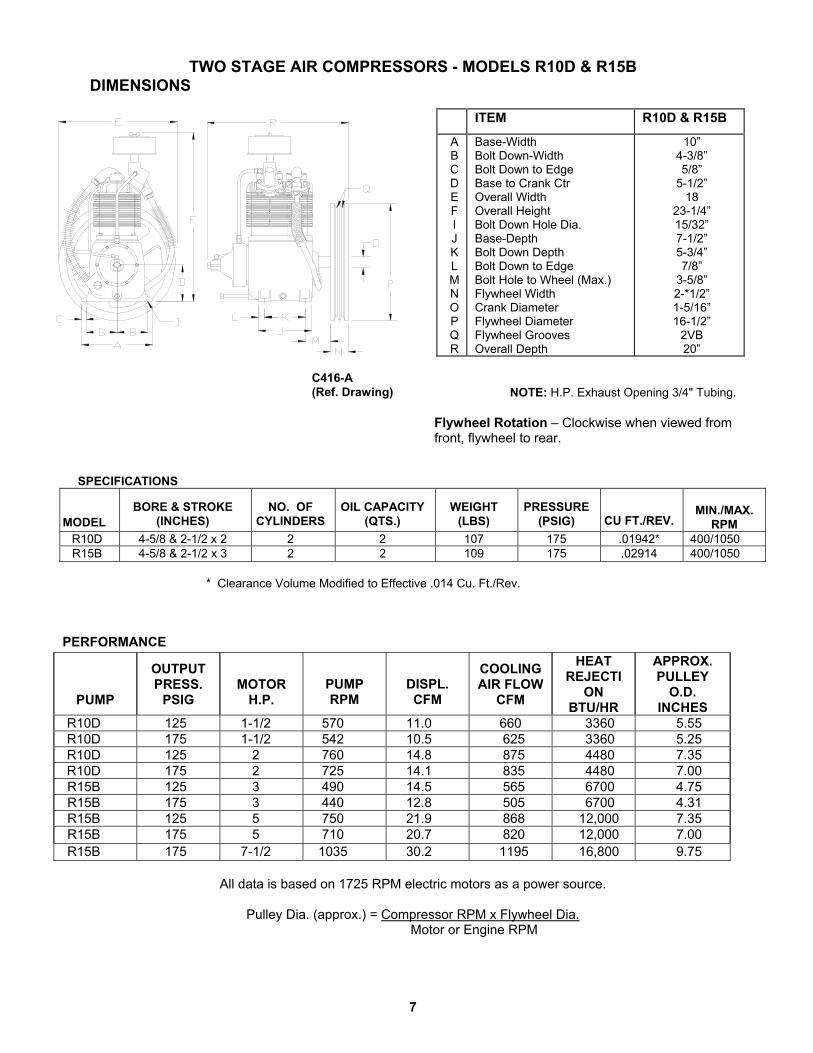
TWO STAGE AIR COMPRESSORS - MODELS R10D & R15B DIMENSIONS
ITEM R10D & R15B
A B C D E F I J K L M N O P Q R
Base-Width Bolt Down-Width Bolt Down to Edge Base to Crank Ctr Overall Width Overall Height Bolt Down Hole Dia. Base-Depth Bolt Down Depth Bolt Down to Edge Bolt Hole to Wheel (Max.) Flywheel Width Crank Diameter Flywheel Diameter Flywheel Grooves Overall Depth
10” 4-3/8” 5/8”
5-1/2” 18
23-1/4” 15/32” 7-1/2” 5-3/4” 7/8”
3-5/8” 2-*1/2” 1-5/16” 16-1/2”
2VB 20”
NOTE: H.P. Exhaust Opening 3/4" Tubing. Flywheel Rotation – Clockwise when viewed from front, flywheel to rear.
SPECIFICATIONS MODEL
BORE & STROKE
(INCHES)
NO. OF
CYLINDERS
OIL CAPACITY
(QTS.)
WEIGHT
(LBS)
PRESSURE
(PSIG)
CU FT./REV.
MIN./MAX.
RPM R10D 4-5/8 & 2-1/2 x 2 2 2 107 175 .01942* 400/1050 R15B 4-5/8 & 2-1/2 x 3 2 2 109 175 .02914 400/1050
* Clearance Volume Modified to Effective .014 Cu. Ft./Rev.
PERFORMANCE
PUMP
OUTPUT PRESS.
PSIG
MOTOR
H.P.
PUMP RPM
DISPL. CFM
COOLING AIR FLOW
CFM
HEAT REJECTI
ON BTU/HR
APPROX. PULLEY
O.D. INCHES
R10D 125 1-1/2 570 11.0 660 3360 5.55 R10D 175 1-1/2 542 10.5 625 3360 5.25 R10D 125 2 760 14.8 875 4480 7.35 R10D 175 2 725 14.1 835 4480 7.00 R15B 125 3 490 14.5 565 6700 4.75 R15B 175 3 440 12.8 505 6700 4.31 R15B 125 5 750 21.9 868 12,000 7.35 R15B 175 5 710 20.7 820 12,000 7.00 R15B 175 7-1/2 1035 30.2 1195 16,800 9.75
All data is based on 1725 RPM electric motors as a power source.
Pulley Dia. (approx.) = Compressor RPM x Flywheel Dia.
Motor or Engine RPM
C416-A (Ref. Drawing)
8
INSTALLATION
WARNING Do not operate unit if damaged during shipping, handling or use. Operating unit if damaged may result in injury.
1. Permanently installed compressors must be located in a clean, well ventilated dry room so compressor
receives adequate supply of fresh, clean, cool and dry air. It is recommended that a compressor, used for painting, be located in a separate room from that area wherein body sanding and painting is done. Abrasive particles or paint, found to have clogged the air intake filters and intake valves, shall automatically void warranty.
2. Compressors should never be located so close to a wall or other obstruction that flow of air through the fan bladed flywheel, which cools the compressor, is impeded. Permanently mounted units should have flywheel at least 12" from wall.
3. Place stationary compressors on firm level ground or flooring. Permanent installations require bolting to floor. Bolt holes in tank or base feet are provided. Before bolting or lagging down, shim compressor level. Avoid putting a stress on a tank foot by pulling it down to floor. This will only result in abnormal vibration, and possible cracking of Air Receiver. It is recommended that optional vibro-isolator pads be installed on unit. Tanks bolted directly to a concrete floor without padding will not be warranted against cracking. Champion vibro-isolators must be used for extended warranty to apply to ASME air receivers.
4. If installing a bare pump or a base mounted unit, make certain the system has adequate pressure limiting controls. Controls could be a pressure switch for start/stop operation or a pilot valve for continuous operation. If a pilot valve is used, the compressor must be equipped with head unloaders. Control air must be piped from the air receiver to the pilot valve.
5. A properly sized air check valve must be installed in the discharge piping, between the compressor outlet and the inlet of any receiver tank(s) in the system.
DANGER Do not install isolating valves between compressor outlet and air receiver. This will cause excessive pressure if valve is closed, and cause injury and equipment damage.
WARNING Always use an air pressure regulating device at the point of use. Failure to do so can result in injury or equipment damage.
CAUTION ● Do not install in an area where ambient temperature is below 32 degrees F or above 100 degrees F.● Do not install unit in an area where air is dirty and/or chemical laden. ● Unit is not to be installed outdoors.
9
INSTALLATION (CONT’D) ELECTRICAL POWER SUPPLY
It is essential that the power supply and the supply wiring are adequately sized and that the voltage
correspond to the unit specifications. Branch circuit protection must be provided at installation a specified in the National Electrical Code.
All wiring should be preformed by a licensed electrian or electrical contractor. Wiring must meet applicable
codes for area of installation. The table gives recommended wire sizes based on the 1999 NEC.
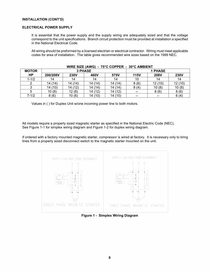
WIRE SIZE (AWG) - 75°C COPPER - 30°C AMBIENT 3 PHASE 1 PHASE MOTOR
HP 200/208V 230V 460V 575V 115V 208V 230V 1-1/2 14 14 14 14 10 14 14
2 14 (14) 14 (14) 14 (14) 14 (14) 8 (6) 12 (10) 12 (10) 3 14 (10) 14 (12) 14 (14) 14 (14) 8 (4) 10 (8) 10 (8) 5 10 (8) 12 (8) 14 (12) 14 (12) -- 8 (6) 8 (6)
7-1/2 8 (6) 10 (6) 14 (10) 14 (10) -- -- 6 (4)
Values in ( ) for Duplex Unit w/one incoming power line to both motors.
All models require a properly sized magnetic starter as specified in the National Electric Code (NEC). See Figure 1-1 for simplex wiring diagram and Figure 1-2 for duplex wiring diagram.
If ordered with a factory mounted magnetic starter, compressor is wired at factory. It is necessary only to bring lines from a properly sized disconnect switch to the magnetic starter mounted on the unit.
Figure 1 - Simplex Wiring Diagram

10
INSTALLATION (CONT’D)
B1258-A (Ref. Drawing)
B1257-A (Ref. Drawing)

11
INSTALLATION (CONT’D)
CAUTION Wiring must be such that when viewing compressor from opposite shaft end, rotation of shaft is clockwise as shown by arrow on guard. Wrong direction rotation for any length of time will result in damage to compressor.
GROUNDING INSTRUCTIONS
This product should be connected to a grounded, metallic, permanent wiring system, or an equipment-grounding terminal or lead on the product.
AIR LINE PIPING
Connection to air system should be of the same size, or larger, than discharge pipe out of unit. The table gives recommended minimum pipe sizes. A union connection to the unit and water drop leg is recommended. Install a flexible connector between the discharge of the unit and the plant air piping. Plant air piping should be periodically inspected for leaks using a soap and water solution for detection on all pipe joints. Air leaks waste energy and are expensive.
Minimum Pipe Sizes For Compressor Air Lines
(Based on clean Smooth Schedule 40 Pipe)
MODEL 25’ 50’ 100’ 200’ 300’ R10D 3/4” 3/4” 3/4” 3/4” 3/4” R15B 3/4” (1”) 3/4” (1”) 3/4” (1”) 1” (1-1/4”) 1” (1-1/4”)
Values in ( ) are for duplex unit.
WARNING Never use plastic pipe or improperly rated metal pipe. Improper piping material can burst and cause injury or property damage.
OPERATION This compressor has been inspected, thoroughly tested and approved at the factory. For this unit to give long satisfactory service it must be installed and operated properly. Simplex units have a pressure switch that senses changes in receiver pressure and automatically starts and stops the compressor at preset pressure limits. If the receiver pressure falls below the cut-in pressure setting of the pressure switch the compressor will run until the cut-out pressure setting of the pressure switch has been reached. Duplex units have lead and lag pressure switches and an automatic alternating system to evenly distribute the load between the two compressors. The pressure switches sense changes in receiver pressure and automatically start and stop the compressor at preset pressure levels. If the receiver pressure falls below the cut-in pressure setting of the lead pressure switch but remains above the cut-in pressure setting of the lag pressure switch, only one compressor will run until receiver pressure reaches the cut-out pressure of the lead pressure switch. The next time the pressure in the receiver drops, the system automatically starts the compressor that was idle. If the receiver pressure falls below the cut-in pressure setting of the lag pressure switch, both compressors run until receiver pressure reaches the cut-out pressure setting of the lead pressure switch.

12
OPERATION (CONT’D) Units furnished with head unloaders are equipped with a needle valve, pilot valve and head unloaders to provide continuous run capabilities. The pilot valve acts as an automatic air switch allowing air to flow from the receiver to the head unloader mechanism, thus actuating it. To operate unit in continuous run, open needle valve located next to pilot valve. The pilot valve is now able to sense receiver pressure. When the receiver pressure reaches the cut-out pressure setting of the pilot valve, the pilot valve opens and air is released to the unloader mechanism. The compressor stops compressing air and runs unloaded until the cut-in pressure setting of the pilot valve has been reached. At this time air released from the unloader mechanism and the compressor starts compressing again. Continuous run is recommended if motor starts exceed 8 starts/hour. Initial Start Up
1. Inspect unit for any visible signs of damage that would have occurred in shipment or during installation.
2. Pull main disconnect switch to unit to assure that no power is coming into the unit. “Lock Out” or “Tag Out” switch. Connect power leads to start.
WARNING Do not attempt to operate compressor on voltage other than that specified on order or on compressor motor.
3. Check compressor oil level. Add oil as required. See “Compressor Oil Specifications” Section. NOTE: Do not mix oil type, weights or brands.
4. Activate main disconnect switch.
5. “Jog” motor and check for proper rotation by direction arrow. If rotation is wrong, reverse input connections on the magnetic starter.
6. Close receiver outlet hand valve and start.
7. With receiver hand valve closed, let machine pump up to operating pressure. At this stage the automatic controls will take over. Check for proper cycling operation.
8. Check for proper operation of any options. Refer to individual option instruction sheet.
9. When the initial run period has shown no operating problems, shut unit down and recheck oil level.
10. Open receiver hand valve. The air compressor unit is now ready for use.
WARNING This unit can start automatically without warning.

13
GUIDE TO MAINTENANCE To obtain reliable and satisfactory service, this unit requires a consistent preventive maintenance schedule. Maintenance schedule pages are included in the back of this manual to aid in keeping the proper records.
WARNING
Before performing any maintenance function, switch main disconnect switch to "off" position to assure no power is entering unit. "Lock Out" or "Tag Out" all sources of power. Be sure all air pressure in unit is relieved. Failure to do this may result in injury or equipment damage.
DAILY MAINTENANCE 1. Check oil level of both compressor and engine if so equipped. Add quality lubricating oil as required. See
Section on "Oil Specifications".
2. Drain moisture from tank by opening tank drain valve located in bottom of tank. Do not open drain valve if tank pressure exceeds 25 PSIG.
3. Turn off compressor at the end of each day's operation. Turn off power supply at wall switch. WEEKLY MAINTENANCE
1. Clean dust and foreign matter from cylinder head, motor, fan blade, air lines, intercooler and tank.
2. Remove and clean intake air filters.
WARNING Do not exceed 15 PSIG nozzle pressure when cleaning element parts with compressed air. Do not direct compressed air against human skin. Serious injury could result. Never wash elements in fuel oil, gasoline or flammable solvent.
3. Check V-belts for tightness. The V-belts must be tight enough to transmit the necessary power to the
compressor. Adjust the V-belts as follows:
a. Remove bolts and guard to access compressor drive.
b. Loosen mounting hardware which secures motor to base. Slide motor within slots of baseplate to desired position.
c. Apply pressure with finger to one belt at midpoint span. Tension is correct if top of belt aligns with bottom of adjacent belt. Make further adjustments if necessary.
d. Check the alignment of pulleys. Adjust if necessary.
e. Tighten mounting hardware to secure motor on base.
f. Re-install guard and secure with bolts.
WARNING Never operate unit without belt guard in place. Removal will expose rotating parts which can cause injury or equipment damage.

14
EVERY 90 DAYS OR 500 HOURS MAINTENANCE 1. Change crankcase oil. Use type and grade oil as specified in the section on "Compressor Oil
Specifications". 2. Check entire system for air leakage around fittings, connections, and gaskets, using soap solution and
brush. 3. Tighten nuts and capscrews as required. 4. Check and clean compressor valves, replace springs, discs and seats when worn or damaged.
CAUTION
Valves must be reinstalled in original position. Valve gaskets should be replaced each time valves are serviced.
5. Pull ring on all pressure relief valves to assure proper operation. GENERAL MAINTENANCE NOTES PRESSURE RELIEF VALVE: The pressure relief valve is an automatic pop valve. Each valve is properly
adjusted for the maximum pressure permitted by tank specifications and working pressure of the unit on which it is installed. If it should pop, it will be necessary to drain all the air out of the tank in order to reseat properly. Do not readjust.
TANK DRAIN VALVE: Drain valve is located at bottom of tank. Open drain valve daily to drain condensation.
Do not open drain valve if tank pressure exceeds 25 PSIG. The automatic tank drain equipped compressor requires draining manually once a week.
PRESSURE SWITCH: The pressure switch is automatic and will start compressor at low pressure and stop
when the maximum pressure is reached. It is adjusted to start and stop compressor at the proper pressure for the unit on which it is installed. Do not readjust.
BELTS: Drive belts must be kept tight enough to prevent slipping. If belts slip or squeak, see V-belt maintenance in preceding section.
CAUTION
If belts are too tight, overload will be put on motor and motor bearings. COMPRESSOR VALVES: If compressor fails to pump air or seems slow in filling up tank, disconnect unit from
power source and remove valves and clean thoroughly, using compressed air and a soft wire brush. After cleaning exceptional care must be taken that all parts are replaced in exactly the same position and all joints must be tight or the compressor will not function properly. When all valves are replaced and connections tight, close hand valve at tank outlet for final test. Valve gaskets should be replaced each time valves are removed from pump.
15
GENERAL MAINTENANCE (Cont'd.) CENTRIFUGAL UNLOADER AND UNLOADER PRESSURE RELEASE VALVE:
The centrifugal unloader is operated by two governor weights. It is totally enclosed and lubricated from the crankcase of the compressor. When compressor starts, the governor weights automatically open compressing the main spring, allowing the unloader pressure release valve to close. When the compressor stops, the main spring returns the governor weights to normal position opening the unloader pressure release valve and unloading the compressor. This prevents overloading the motor when starting. If air continues to escape through the governor or unloader pressure release valve while operating, this is an indication that the unloader pressure release valve is not closing tightly and may be held open by foreign substance which has lodged on the seat. In order to correct this, remove the governor release valve cap, giving access to unloader pressure release valve spring and ball. Clean thoroughly and return parts in the same order in which they were removed. Loose drive belts can also cause unloader to leak by preventing the compressor from reaching proper speed. (See “BELTS” above).
CHECK VALVE: The check valve closes when the compressor stops operating, preventing air from flowing out of the tank through the pressure release valve. After the compressor stops operating, if air continues to escape through the release valve, it is an indication that the check valve is leaking. This can be corrected by removing check valve and cleaning disc and seat. If check valve is worn badly, replace same.
WARNING
Before removing check valve be sure all air is drained out of tank and power is disconnected. Failure to do so may result in injury or equipment damage.
THE INTERSTAGE PRESSURE RELIEF VALVE is provided to protect against interstage over pressure and
is factory set for maximum pressure of 75 PSIG. DO NOT RESET If the pressure relief valve pops, it indicates trouble. Shut down the unit immediately and determine and correct the malfunction. Inspect the head valves. Serious damage can result if not corrected and can lead to complete destruction of the unit. Tampering with the interstage pressure relief valve, or plugging the opening destroys the protection provided and voids all warranty.
COMPRESSOR LUBRICATION: Fill crankcase to proper level as indicated by oil sight gauge. Keep crankcase
filled as required by usage. It is recommended that only Champlub recip lubricant be used. This is a 30-weight, non-detergent industrial oil with rust and oxidation inhibitors specially formulated for reciprocating compressors. Do not mix oil types, weights or brands.
MOTOR LUBRICATION: Long time satisfactory operation of an electric motor depends in large measure on proper lubrication of the bearings. Bearing grease will lose its lubricating ability overtime, not suddenly. Refer to the motor manufacturer’s instructions for the type of grease and lubrication intervals. PILOT VALVE: The pilot valve actuates the head unloader mechanism to provide a means of stopping or starting the compression of air by the compressor without stopping or starting the electric motor.
16
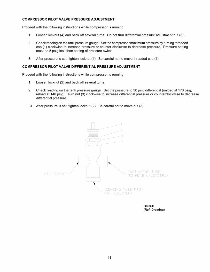
COMPRESSOR PILOT VALVE PRESSURE ADJUSTMENT Proceed with the following instructions while compressor is running:
1. Loosen locknut (4) and back off several turns. Do not turn differential pressure adjustment nut (3).
2. Check reading on the tank pressure gauge. Set the compressor maximum pressure by turning threaded cap (1) clockwise to increase pressure or counter clockwise to decrease pressure. Pressure setting must be 5 psig less than setting of pressure switch.
3. After pressure is set, tighten locknut (4). Be careful not to move threaded cap (1).
COMPRESSOR PILOT VALVE DIFFERENTIAL PRESSURE ADJUSTMENT Proceed with the following instructions while compressor is running:
1. Loosen locknut (2) and back off several turns. 2. Check reading on the tank pressure gauge. Set the pressure to 30 psig differential (unload at 170 psig,
reload at 140 psig). Turn nut (3) clockwise to increase differential pressure or counterclockwise to decrease differential pressure. 3. After pressure is set, tighten locknut (2). Be careful not to move nut (3).
B890-B
(Ref. Drawing)

17
COMPRESSOR OIL SPECIFICATIONS
Compressors are factory filled with CHAMPLUB hydrocarbon based recip lubricant. This is an ISO 100 non-detergent industrial lubricant with rust and oxidation inhibitors specially formulated for reciprocating compressors. It is recommended this compressor be maintained using this oil for ambient temperatures above 32°F.
CHAMPLUB synthetic is a premium grade diester based synthetic lubricant providing excellent performance in high temperature applications.
CAUTION Do not mix oil types, weights or brands.
NOTES:
1. Normal break-in period of Champion air compressors is 25 hours.
2. For the first 100 hours of compressor operation, a careful and regular check of the oil level should be made. Maintain oil level at the full line.
CHANGING TO SYNTHETIC LUBRICANT
(Applies to diester based synthetic lubricant only)
If changing to synthetic lubricant, the following steps must be completed.
1. Compressor must run for a 25 hour break-in period using ChampLub ISO 100 oil.
2. Thoroughly drain existing oil from crankcase.
3. Fill crankcase with a full charge of synthetic lubricant.
4. Run compressor for 200 hours.
5. Stop compressor and thoroughly drain the synthetic lubricant.
6. Add a full charge of synthetic lubricant.
7. Compressor now ready to run for extended period before next lubricant change. made. Maintain oil level at the full line.
LUBRICANT
CHAMPLUB DESCRIPTION PART NUMBER
1 – Quart Case (12/case) P12612A 1 – Gallon Case (4/case) P12613A 5 – Gallon Pail P12614A 55 – Gallon Drum P12615A CHAMPLUB SYNTHETIC
DESCRIPTION PART NUMBER 1 – Quart Case (12/case) P13179A 1 – Gallon Case (4/case) P13180A 5 – Gallon Pail P11506A 55 – Gallon Drum P13181A
TORQUE VALVES
SPECIFIC APPLICATION FASTENER SIZE & THREAD TORQUE INCH-POUNDS BEARING HOUSING BOLT 3/8 – 16 400 CYLINDER FLANGE BOLT 7/16 – 20 400 CONNECTING ROD BOLT 5-16 – 18 230 MANIFOLD BOLT 3/8 – 16 200 FLYWHEEL BOLT 1/2 – 13 600

18
TROUBLE SHOOTING CHART FOR COMPRESSOR
Always disconnect unit from power supply and relieve all pressure from air tank before performing any maintenance. Failure to do so may result in equipment damage or injury. ALock Out" or "Tag Out" all power sources.
WARNING Never operate unit without belt guard in place.
Never use gasoline or flammable solvent on or around compressor unit. Explosion may result.
Troubleshooting Chart Symptom Possible Cause(s) Corrective Action
Motor will not start.
1. Main switch and fuses open. 2. Starter heater coils open. 3. Starter tripped 4. Defective pressure switch- contacts will not close 5. Low voltage.
1. Check all fuses and switches. Check for loose or faulty wires.
2. Check overload relay in starter. Reset starter.
3. Reset starter. If starter trips repeatedly, have electrical system inspected by an electrician.
4. Repair or replace pressure switch.
Warning – Relieve tank pressure before servicing. 5. Check with voltmeter. Be sure voltage corresponds to unit specifications.
Starter trips repeatedly. 1. Improperly adjusted pressure switch. 2. Faulty check valve. 3. Incorrect fuse size or magnetic starter
heaters. 4. Low voltage. 5. Defective motor.
1. Adjust or replace.
Warning – Relieve tank pressure before servicing. 2. Clean or replace
Warning – Relieve tank pressure before servicing. 3. Be sure that fuses and heaters are
properly rated. 4. Check with voltmeter. Be sure
voltage corresponds to unit specifications.
5. Replace motor. Tank pressure builds up slowly. 1. Air leaks.
2. Dirty air filter. 3. Defective compressor valves
1. Tighten fittings. 2. Clean or replace. 3. Install new valve plate assembly.
Tank pressure builds up quickly. 1. Excessive water in tank. 1. Drain tank. Discharge pressure relief valve pops off while compressor is running.
1. Wrong pressure switch setting. 2. Defective ASME relief valve.
1. Adjust to correct setting. 2. Replace valve.
Warning – Relieve tank pressure before servicing.
Compressor will not unload (Units with head unloaders)
1. Wrong pilot valve setting. 2. Defective pilot valve. 3. Lack of air to pilot valve..
1. Adjust to correct setting 2. Replace pilot valve. 3. Open needle valve to pilot valve.
Excessive belt wear. 1. Pulley out of alignment. 2. Belts too tight or too loose.
1. Realign motor pulley. 2. Adjust belt tension.
Compressor runs hot. 1. Improper flywheel rotation 2. Defective compressor valves. 3. Dirty air filter. 4. Dirty cylinder and/or intercooler.
1. Check for correct rotation. (Counter clockwise when viewed from drive side. 2. Install new valve plate assembly. 3. Clean or replace. 4. Clean cylinder fins and/or intercooler.
Interstage pressure relief valve pops off. 1. Defective compressor valves. 1. Install new valves. Excessive oil consumption. 1. Dirty air filter.
2. Wrong oil viscosity. 3. Oil leaks. 4. Worn piston rings. 5. Scored cylinder
1. Clean or replace. 2. Refill with proper viscosity oil. 3. Tighten bolts. Replace gaskets. 4. Replace rings. 5. Replace cylinder.
19
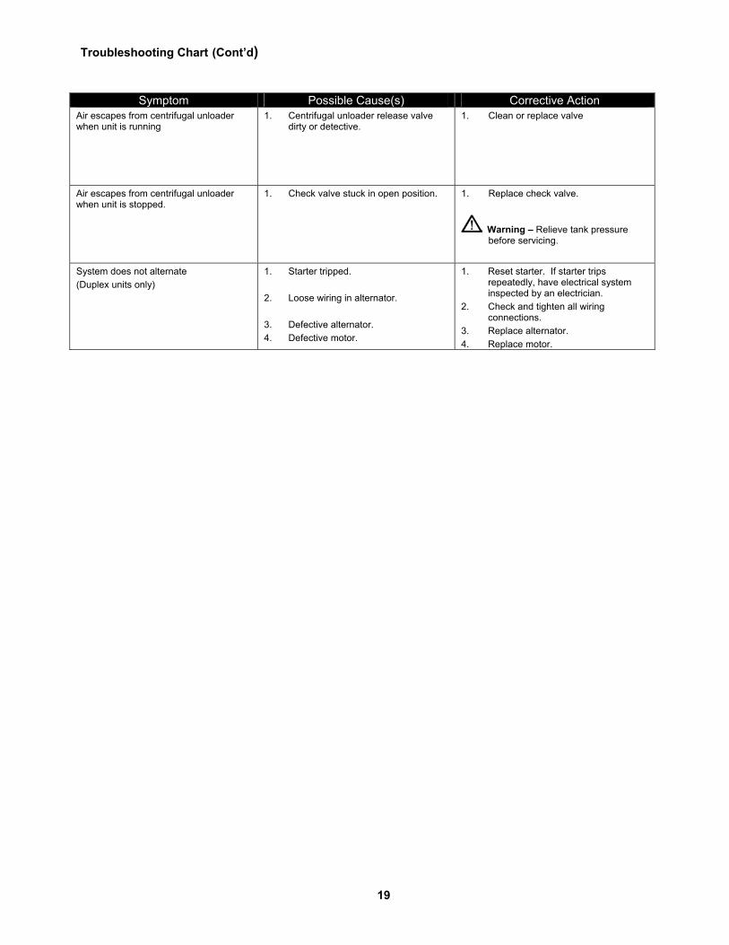
Troubleshooting Chart (Cont’d)
Symptom Possible Cause(s) Corrective Action Air escapes from centrifugal unloader when unit is running
1. Centrifugal unloader release valve dirty or detective.
1. Clean or replace valve
Air escapes from centrifugal unloader when unit is stopped.
1. Check valve stuck in open position. 1. Replace check valve.
Warning – Relieve tank pressure before servicing.
System does not alternate (Duplex units only)
1. Starter tripped. 2. Loose wiring in alternator. 3. Defective alternator. 4. Defective motor.
1. Reset starter. If starter trips repeatedly, have electrical system inspected by an electrician.
2. Check and tighten all wiring connections.
3. Replace alternator. 4. Replace motor.

20
PARTS ILLUSTRATION MODELS: HR1-3, HR1-6, HR1-8, HR2-3, HR2-6, HR2-8, HR3-3, HR3-6, HR3-8, HR3-12, HR5-3, HR5-6, HR5-8, HR5-12, HR7F-6, HR7F-8 & HR7F-12
C454-A (Ref. Drawing)

21
REPAIR PARTS LIST
MODELS HR1-3 HR1-6 HR1-8 HR2-3 HR2-6 HR2-8 HR3-3 HR3-6 1. Pump R10D R10D R10D R10D R10D R10D R15B R15B 2. Pressure Gauge M519C M519C M519C M519C M519C M519C M519C M519C 3. Belt Guard Z307 Z307 Z307 Z307 Z307 Z307 Z307 Z307 4. Drain Valve M2684 M2684 M2684 M2684 M2684 M2684 M2684 M2684 5. Check Valve P05822A P05822A P05822A P05822A P05822A P05822A P05822A P05822A 6. Bucket High Drain Z1541 Z1541 Z1541 Z1541 Z1541 Z1541 Z1541 Z1541
125 PSIG P14205A P14205A P14205A P14205A P14205A P14205A P14205A P14205A 7. Pressure Switch 175 PSIG P14202A P14202A P14202A P14202A P14202A P14202A P14202A P14202A 8. Pressure Relief Valve M2843 M2843 M2843 M2843 M2843 M2843 M2843 M2843 9. Motor 1-1/2 HP 1-1/2 HP 1-1/2 HP 2 HP 2 HP 2-HP 3 HP 3HP 10. Tank P04390D P01136D P01164D P04390D P01136D P01164D P04390D P01136D 11. Isolation Valve M3590 M3590 M2686 M3590 M3590 M3590 M3590 M3590
P07986A P07986A P07986A PULLEY PULLEY PULLEY P11658A P11658A P11658A *12. Pulley 125 PSIG P08509A P08509A P08509A
BUSHING BUSHING BUSHING
P11121B P11121B
P11703A P11703A P11703A PULLEY PULLEY PULLEY P09423A P09423A P09423A *12. Pulley 175 PSIG P09315B P09315B P09315B
BUSHING BUSHING BUSHING
M4309D M4309D
13. Belts 4L650 (2) 4L650 (2) 4L650 (2) 5L680 (2) 5L680 (2) 5L680 (2) 5L650 (2) 5L650 (2) HR3-8 HR3-12 HR5-3 HR5-6 HR5-8 HR5-12 HR7F-6 HR7F-8 HR5-8 1. Pump R15B R15B R15B R15B R15B R15B R15B R15B R15B 2. Pressure Gauge M519C M519C M519C M519C M519C M519C M519C M519C M519C 3. Belt Guard Z307 Z307 Z307 Z307 Z307 Z307 Z307 Z307 Z307 4. Drain Valve M2684 M2684 M2684 M2684 M2684 M2684 M2684 M2684 M2684 5. Check Valve P05822A P05822A P05822A P05822A P05822A P05822A P05822A P05822A P05822A 6. Bucket High Drain Z1541 Z1541 Z1541 Z1541 Z1541 Z1541 Z1541 Z1541 Z1541
125 PSIG P14205A P14205A P14205A P14205A P14205A P14205A P14205A P14205A P14205A 7. Pressure Switch 175 PSIG P14202A P14202A P14202A P14202A P14202A P14202A P14202A P14202A P14202A 8. Pressure Relief Valve M2843 M2843 M2843 M2843 M2843 M2843 M2843 M2843 M2843 9. Motor 3 HP 3 HP 5 HP 5 HP 5 HP 5 HP 7.5 HP 7..5 HP 7.5 HP 10. Tank P01164D P01596D P04390D P01136D P01164D P01596D P01136D P01164D P01596D 11. Isolation Valve M3590 M2686 M3590 M3590 M3590 M2686 M3590 M3590 M2686
P07981A P07981A P07981A PULLEY PULLEY PULLEY P05607A P05607A P05607A *12.Pulley 125PSIG P11121B P11121B P11870C P11870C P11870C P11870C
BUSHING BUSHING BUSHING P07981A P07981A P07981A PULLEY PULLEY PULLEY P05607A P05607A P05607A *12.Pulley 175 PSIG M4309D M4309D M7009D M7009D M7009D M7009D
BUSHING BUSHING BUSHING 13. Belts 5L650 (2) 5L650 (2) 5L680 (2) 5L680 (2) 5L680 (2) 5L680 (2) B68 (2) B68 (2) B68 (2)
* NOTE: 2 HP UNITS WITH SINGLE PHASE MOTOR USE: PULLEY: P11870C (125 PSIG); M7009D (175PSIG) BELTS: 5L680 (2)
22
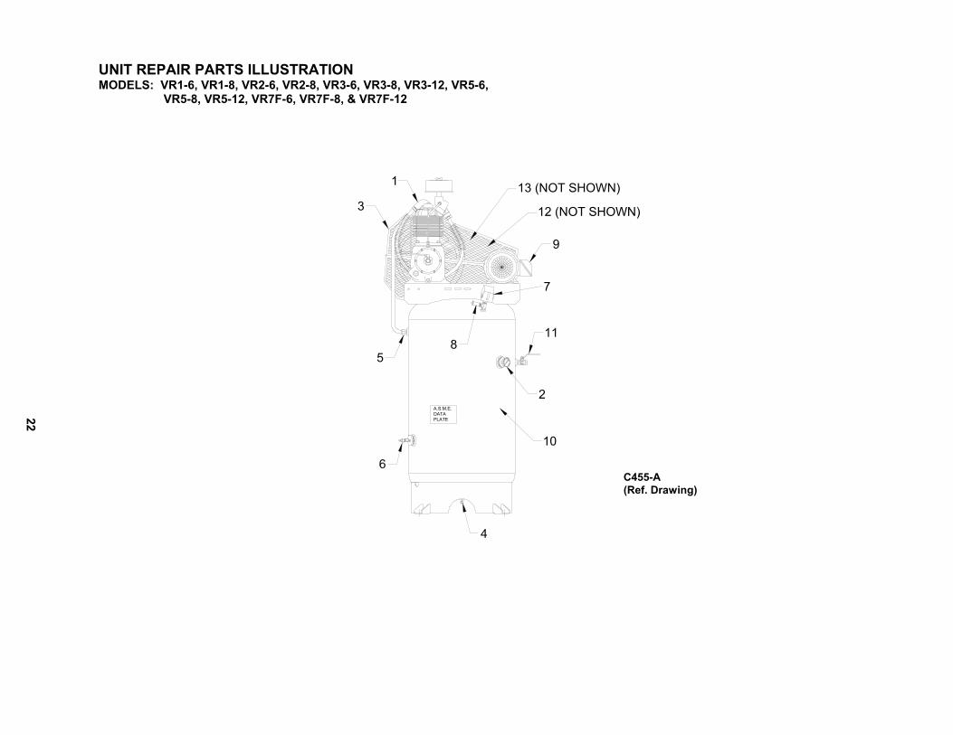
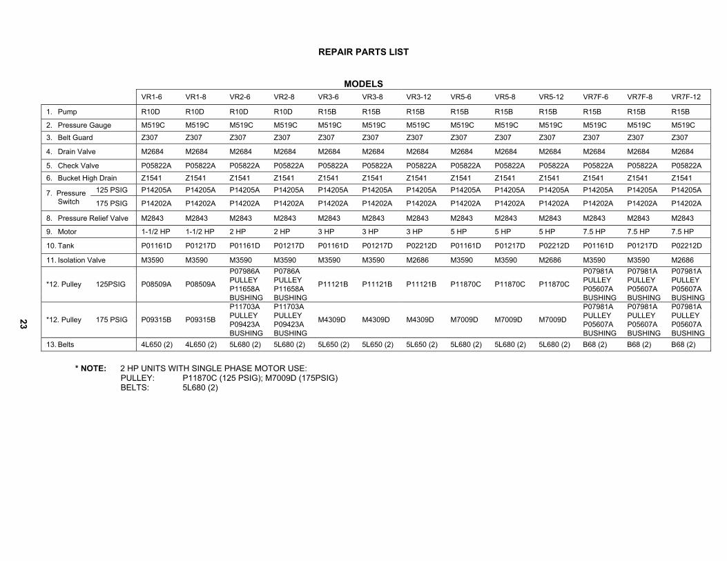
UNIT REPAIR PARTS ILLUSTRATION MODELS: VR1-6, VR1-8, VR2-6, VR2-8, VR3-6, VR3-8, VR3-12, VR5-6, VR5-8, VR5-12, VR7F-6, VR7F-8, & VR7F-12
A.S.M.E.
PLATEDATA
5
3
1 13 (NOT SHOWN)
12 (NOT SHOWN)
9
10
4
C455-A (Ref. Drawing)
23
REPAIR PARTS LIST
MODELS VR1-6 VR1-8 VR2-6 VR2-8 VR3-6 VR3-8 VR3-12 VR5-6 VR5-8 VR5-12 VR7F-6 VR7F-8 VR7F-12
1. Pump R10D R10D R10D R10D R15B R15B R15B R15B R15B R15B R15B R15B R15B
2. Pressure Gauge M519C M519C M519C M519C M519C M519C M519C M519C M519C M519C M519C M519C M519C
3. Belt Guard Z307 Z307 Z307 Z307 Z307 Z307 Z307 Z307 Z307 Z307 Z307 Z307 Z307
4. Drain Valve M2684 M2684 M2684 M2684 M2684 M2684 M2684 M2684 M2684 M2684 M2684 M2684 M2684
5. Check Valve P05822A P05822A P05822A P05822A P05822A P05822A P05822A P05822A P05822A P05822A P05822A P05822A P05822A
6. Bucket High Drain Z1541 Z1541 Z1541 Z1541 Z1541 Z1541 Z1541 Z1541 Z1541 Z1541 Z1541 Z1541 Z1541 125 PSIG P14205A P14205A P14205A P14205A P14205A P14205A P14205A P14205A P14205A P14205A P14205A P14205A P14205A 7. Pressure
Switch 175 PSIG P14202A P14202A P14202A P14202A P14202A P14202A P14202A P14202A P14202A P14202A P14202A P14202A P14202A
8. Pressure Relief Valve M2843 M2843 M2843 M2843 M2843 M2843 M2843 M2843 M2843 M2843 M2843 M2843 M2843
9. Motor 1-1/2 HP 1-1/2 HP 2 HP 2 HP 3 HP 3 HP 3 HP 5 HP 5 HP 5 HP 7.5 HP 7.5 HP 7.5 HP
10. Tank P01161D P01217D P01161D P01217D P01161D P01217D P02212D P01161D P01217D P02212D P01161D P01217D P02212D
11. Isolation Valve M3590 M3590 M3590 M3590 M3590 M3590 M2686 M3590 M3590 M2686 M3590 M3590 M2686 P07986A P0786A P07981A P07981A P07981A PULLEY PULLEY PULLEY PULLEY PULLEY P11658A P11658A P05607A P05607A P05607A *12. Pulley 125PSIG P08509A P08509A
BUSHING BUSHING
P11121B P11121B P11121B P11870C P11870C P11870C
BUSHING BUSHING BUSHING P11703A P11703A P07981A P07981A P07981A PULLEY PULLEY PULLEY PULLEY PULLEY P09423A P09423A P05607A P05607A P05607A *12. Pulley 175 PSIG P09315B P09315B
BUSHING BUSHING
M4309D M4309D M4309D M7009D M7009D M7009D
BUSHING BUSHING BUSHING 13. Belts 4L650 (2) 4L650 (2) 5L680 (2) 5L680 (2) 5L650 (2) 5L650 (2) 5L650 (2) 5L680 (2) 5L680 (2) 5L680 (2) B68 (2) B68 (2) B68 (2)
* NOTE: 2 HP UNITS WITH SINGLE PHASE MOTOR USE: PULLEY: P11870C (125 PSIG); M7009D (175PSIG) BELTS: 5L680 (2)
24
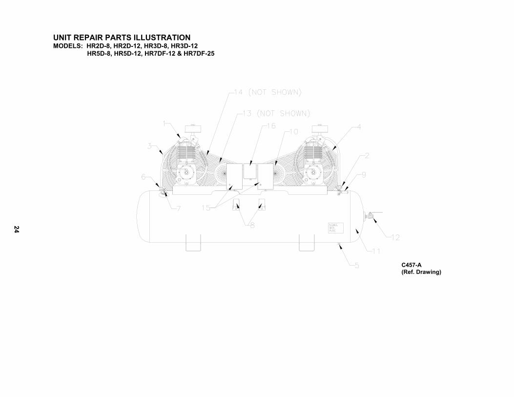
UNIT REPAIR PARTS ILLUSTRATION MODELS: HR2D-8, HR2D-12, HR3D-8, HR3D-12 HR5D-8, HR5D-12, HR7DF-12 & HR7DF-25
C457-A (Ref. Drawing)

25
REPAIR PARTS LIST
MODELS HR2D-8 HR2D-12 HR3D-8 HR3D-12 HR5D-8 HR5D-12 HR7DF-12 HR7DF-25 1. Pump R10D R10D R15B R15B R15B R15B R15B R15B
2. Pressure Gauge M519C M519C M519C M519C M519C M519C M519C M519C
3. Belt Guard Z307 Z307 Z307 Z307 Z307 Z307 Z307 Z307
4. Belt Guard Z1432 Z1432 Z1432 Z1432 Z1432 Z1432 Z1432 Z1432 5. Drain Valve M2684 M2684 M2684 M2684 M2684 M2684 M2684 M2684 6. Check Valve P05822A P05822A P05822A P05822A P05822A P05822A P05822A P05822A
7. Bucket High Drain Z1541 Z1541 Z1541 Z1541 Z1541 Z1541 Z1541 Z1541
125 PSIG P14205A P14205A P14205A P14205A P14205A P14205A P14205A P14205A 8.Pressure Switch
175 PSIG P14202A P14202A P14202A P14202A P14202A P14202A P14202A P14202A
9. Pressure Relief Valve M2843 M2843 M2843 M2843 M2843 M2843 M2843 M2843
10. Motor 2 HP 2 HP 3 HP 3HP 5 HP 5-HP 7.5 HP 7.5HP
11. Tank P05767D P14130D P05767D P14130D P05767D P14130D P14130D P05763D
12. Isolation Valve M2686 M2686 M2686 M2686 M2686 M2686 M2686 M2686
P07986A (2) P07986A (2) P07981A (2) P07981A (2)
PULLEY PULLEY PULLEY PULLEY
P11658A (2) P11658A (2) P05607A (2) P05607A (2) *13. Pulley 125PSIG
BUSHING BUSHING
P11121B (2) P11121B (2) P11870C (2) P11870C (2)
BUSHING BUSHING
P11703A (2) P11703A (2) P07981A (2) P07981A (2)
PULLEY PULLEY PULLEY PULLEY
P09423A (2) P09423A (2) P05607A (2) P05607A (2) *13. Pulley 175 PSIG
BUSHING BUSHING
M4309D (2) M4309D (2) M7009D (2) M7009D (2)
BUSHING BUSHING
14. Belts 5L680 (4) 5L680 (4) 5L650 (4) 5L650 (24 5L680 (4) 5L680 (4) B68 (4) B68 (4)
15. Starter CONSULT FACTORY 16. Alternator CONSULT FACTORY
* NOTE: 2 HP UNITS WITH SINGLE PHASE MOTOR USE: PULLEY: P11870C (125 PSIG); M7009D (175PSIG) BELTS: 5L680 (4)
26
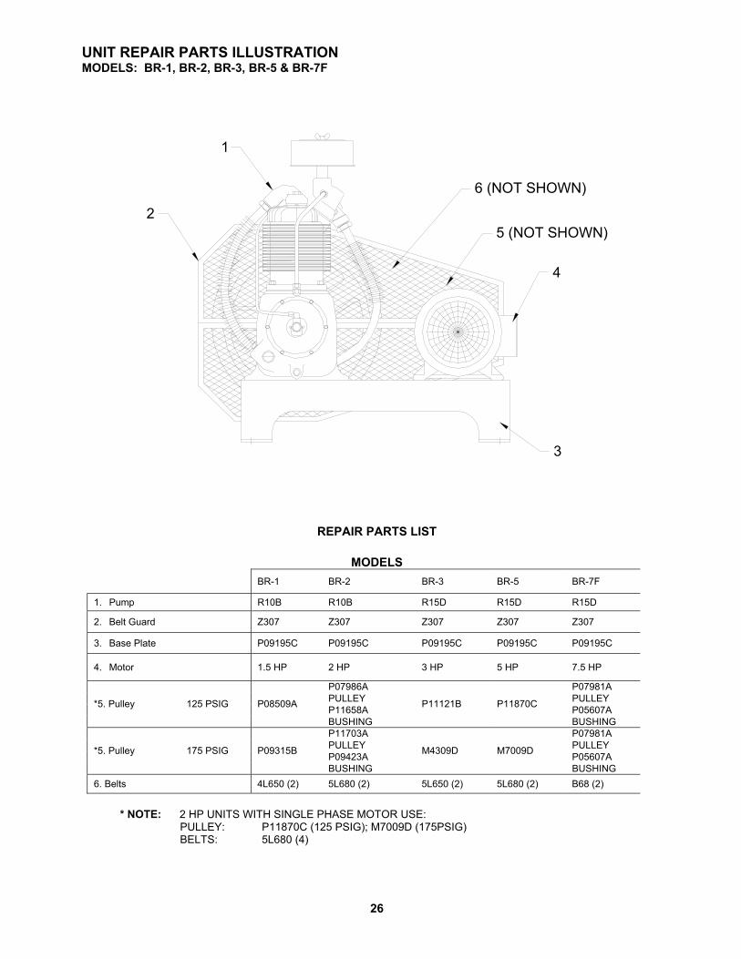
UNIT REPAIR PARTS ILLUSTRATION MODELS: BR-1, BR-2, BR-3, BR-5 & BR-7F
3
4
5 (NOT SHOWN)
6 (NOT SHOWN)
1
2
REPAIR PARTS LIST
MODELS
BR-1 BR-2 BR-3 BR-5 BR-7F
1. Pump R10B R10B R15D R15D R15D
2. Belt Guard Z307 Z307 Z307 Z307 Z307
3. Base Plate P09195C P09195C P09195C P09195C P09195C
4. Motor 1.5 HP 2 HP 3 HP 5 HP 7.5 HP
P07986A P07981A PULLEY PULLEY P11658A P05607A *5. Pulley 125 PSIG P08509A
BUSHING
P11121B P11870C
BUSHING P11703A P07981A PULLEY PULLEY P09423A P05607A *5. Pulley 175 PSIG P09315B
BUSHING
M4309D M7009D
BUSHING 6. Belts 4L650 (2) 5L680 (2) 5L650 (2) 5L680 (2) B68 (2)
* NOTE: 2 HP UNITS WITH SINGLE PHASE MOTOR USE: PULLEY: P11870C (125 PSIG); M7009D (175PSIG)
BELTS: 5L680 (4)
27
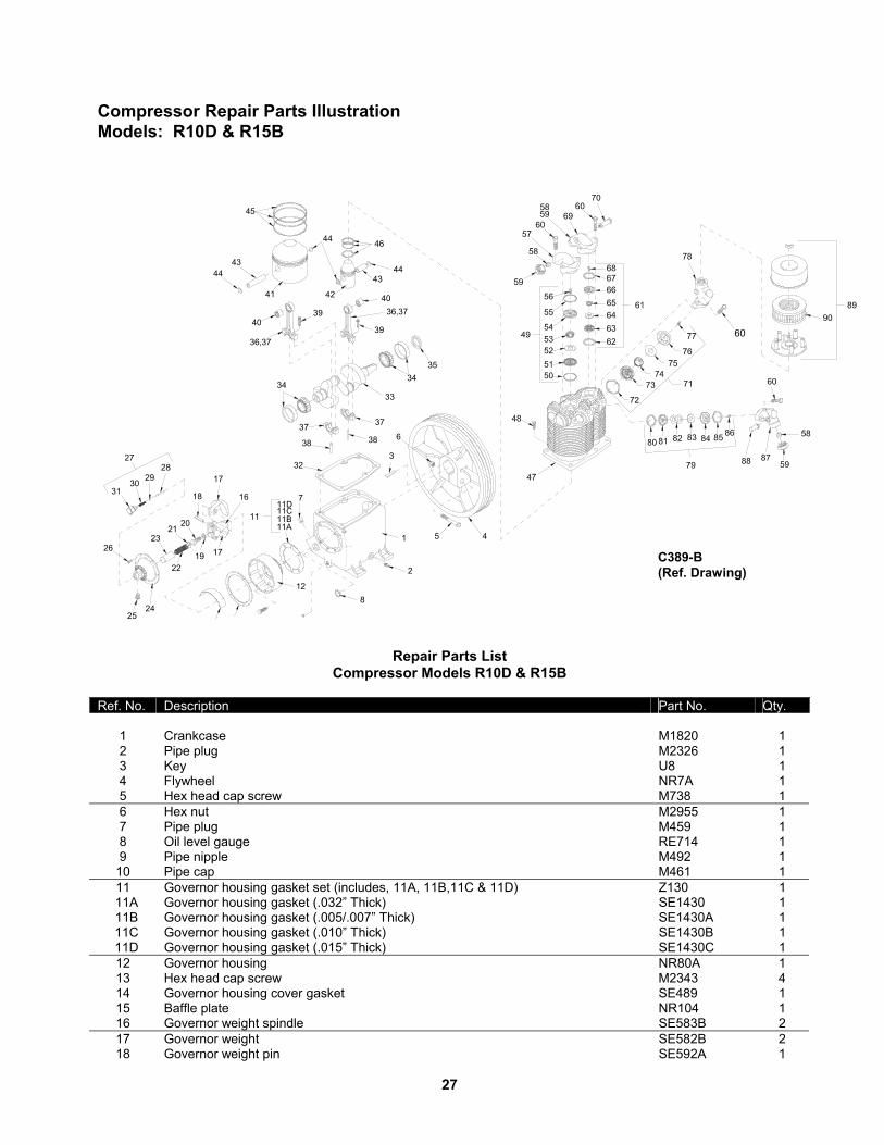
Compressor Repair Parts Illustration Models: R10D & R15B
1
2
3
45
7
8
11A11B
11D11C
12
6
37
38
3334
3435
3738
36,37
39
40
36,37
40
4443
41
39
44
45
4443
42
46
17
18 16
1719
2021
23
22
2425
26
3130
2928
2732
11
Repair Parts List
Compressor Models R10D & R15B Ref. No. Description Part No. Qty.
1 Crankcase M1820 1 2 Pipe plug M2326 1 3 Key U8 1 4 Flywheel NR7A 1 5 Hex head cap screw M738 1 6 Hex nut M2955 1 7 Pipe plug M459 1 8 Oil level gauge RE714 1 9 Pipe nipple M492 1
10 Pipe cap M461 1 11 Governor housing gasket set (includes, 11A, 11B,11C & 11D) Z130 1
11A Governor housing gasket (.032” Thick) SE1430 1 11B Governor housing gasket (.005/.007” Thick) SE1430A 1 11C Governor housing gasket (.010” Thick) SE1430B 1 11D Governor housing gasket (.015” Thick) SE1430C 1
12 Governor housing NR80A 1 13 Hex head cap screw M2343 4 14 Governor housing cover gasket SE489 1 15 Baffle plate NR104 1 16 Governor weight spindle SE583B 2 17 Governor weight SE582B 2 18 Governor weight pin SE592A 1
C389-B (Ref. Drawing)

28
Repair Parts List Compressor Models R10D & R15B
Ref. No. Description Part No. Qty.
19 Lock washer M3468 1 20 Hex head cap screw M2345 1 21 Flat washer M912A 1 22 Governor spring SE590 1 23 Spring sleeve SE587 1 24 Governor housing cover RE10100A 1 25 Unloader muffler assembly Z4593 1 26 Hex head machine screw M3473 6 27 Release valve assembly Z12414A 1 28 Release valve plunger SE586B 1 29 Release valve ball P07841A 1 30 Release valve spring SE591 1 31 Release valve body NR101 1 32 Cylinder flange gasket NR29A 1 33 Crankshaft (Model R10D) R105 1 33 Crankshaft (Model R15B) R155 1 34 Main Bearing ZRN16 2 35 Oil seal OSN4 1 36 Connecting rod assembly model R10D low pressure (includes items 37 thru 40) Z750 1 36 Connecting rod assembly model R10D high pressure (includes items 37 thru 40) Z752 1 36 Connecting rod assembly model R15B (includes items 37 thru 40) Z752 2 37 Connecting rod (not sold separately) --- -- 38 Oil dipper (Model R10D) R1025 2 38 Oil dipper (Model R15B) R1524 2 39 Connecting rod bolt M1583 4 40 Piston pin bearing R1037 2 41 Low pressure piston with pin (includes items 43 & 44) ZR154 1 42 High pressure piston with pin (includes items 43 & 44) ZP02709C 1 43 Piston pin R1021 2 44 Piston pin retaing ring R10102 4 45 Low pressure piston ring set Z798 1 46 High pressure piston ring set Z797 1 47 Cylinder P12237D 1 48 Hex head cap screw M2345 6 49 Low pressure discharge valve assembly Z813 1 50 Valve gasket P04135A 1 51 Discharge valve seat M2097 1 52 Valve disc RE1061 1 53 Valve spring RE1059 1 54 Discharge valve cage M2099 1 55 Valve gasket P04135A 1 56 Hex head machine screw M3220 1 57 Low pressure discharge manifold RE102E 1 58 Ferrule SE542 3 59 Compression nut SE541 3 60 Hex head cap screw P05005A 8 61 High pressure discharge valve assembly Z115 1 62 Valve gasket P04137A 1 63 Discharge valve seat RE757A 1 64 Valve disc RE1062 1 65 Valve spring RE760 1 66 Discharge valve cage M2100 1 67 Valve gasket P04136A 1 68 Hex head machine screw M3220 1 69 High pressure discharge manifold P12303B 1 70 Pressure relief valve P09704A 1
*71 Low pressure intake valve assembly Z812 1
29
Repair Parts List Compressor Models R10D & R15B
Ref. No. Description Part No. Qty.
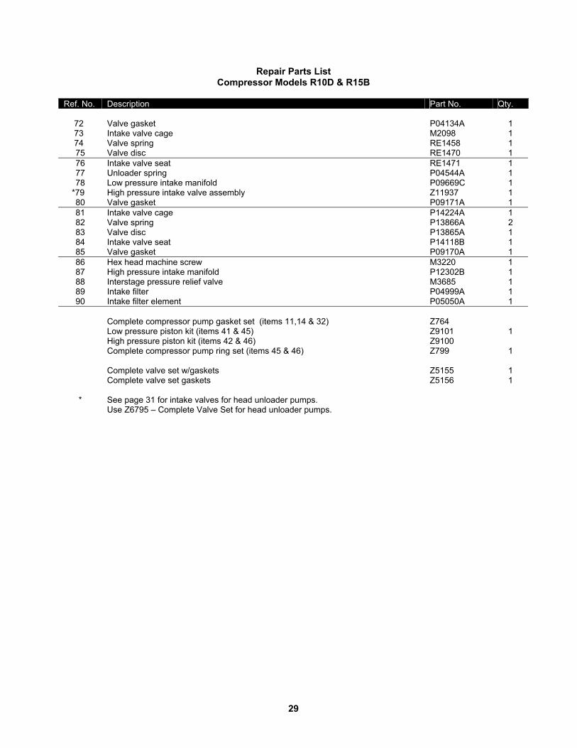
72 Valve gasket P04134A 1 73 Intake valve cage M2098 1 74 Valve spring RE1458 1 75 Valve disc RE1470 1 76 Intake valve seat RE1471 1 77 Unloader spring P04544A 1 78 Low pressure intake manifold P09669C 1
*79 High pressure intake valve assembly Z11937 1 80 Valve gasket P09171A 1 81 Intake valve cage P14224A 1 82 Valve spring P13866A 2 83 Valve disc P13865A 1 84 Intake valve seat P14118B 1 85 Valve gasket P09170A 1 86 Hex head machine screw M3220 1 87 High pressure intake manifold P12302B 1 88 Interstage pressure relief valve M3685 1 89 Intake filter P04999A 1 90 Intake filter element P05050A 1 Complete compressor pump gasket set (items 11,14 & 32) Z764 Low pressure piston kit (items 41 & 45) Z9101 1 High pressure piston kit (items 42 & 46) Z9100 Complete compressor pump ring set (items 45 & 46) Z799 1 Complete valve set w/gaskets Z5155 1 Complete valve set gaskets Z5156 1 * See page 31 for intake valves for head unloader pumps. Use Z6795 – Complete Valve Set for head unloader pumps.

30
Compressor Repair Parts Illustration Models: R10D & R15B
ITEM
PART NO.
NAME
REQ.
1 2 3 4 5 6 7
M2868
ZSB250A M2864
ZUB375 M2864 M2881 Z9140
Compression Fitting Tube, Unloading w/Fittings Compression Fitting Breather Tube w/Fittings Compression Fitting Compression Fitting Intercooler w/Fittings
1 1 1 1 1 1 1
C420-A (Ref. Drawing)
31
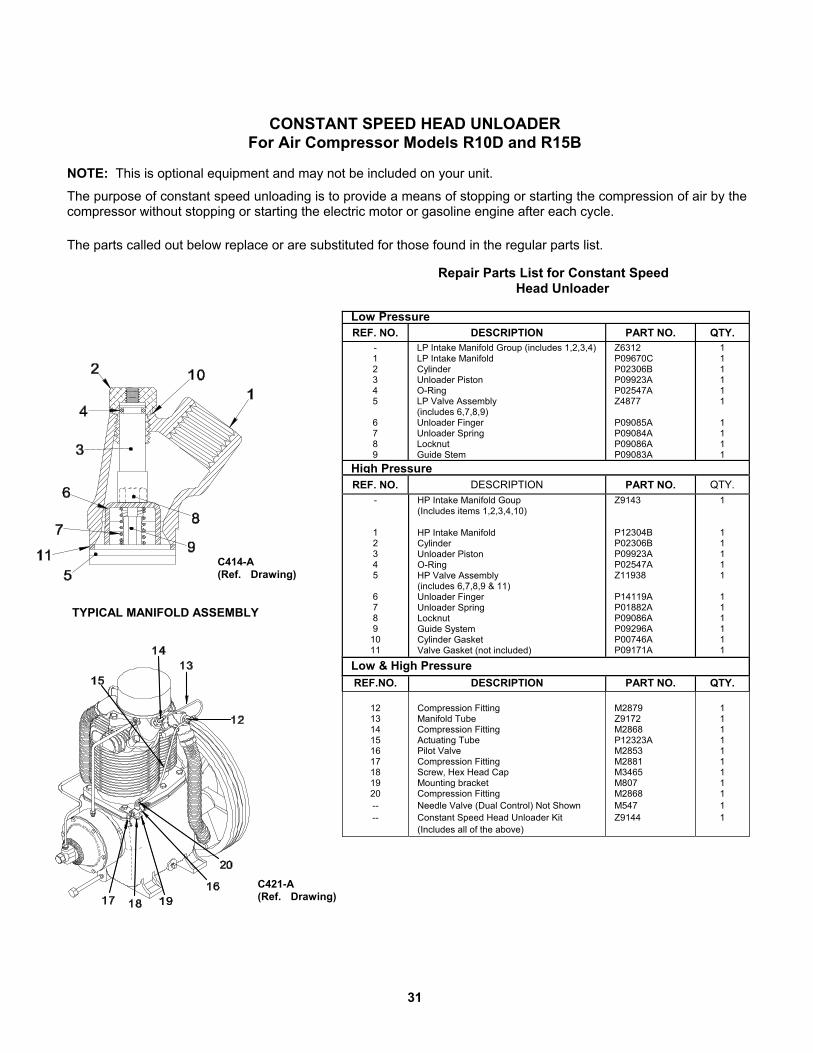
CONSTANT SPEED HEAD UNLOADER For Air Compressor Models R10D and R15B NOTE: This is optional equipment and may not be included on your unit.
The purpose of constant speed unloading is to provide a means of stopping or starting the compression of air by the compressor without stopping or starting the electric motor or gasoline engine after each cycle.
The parts called out below replace or are substituted for those found in the regular parts list. Repair Parts List for Constant Speed Head Unloader
Low Pressure REF. NO. DESCRIPTION PART NO. QTY.
- 1 2 3 4 5 6 7 8 9
LP Intake Manifold Group (includes 1,2,3,4) LP Intake Manifold Cylinder Unloader Piston O-Ring LP Valve Assembly (includes 6,7,8,9) Unloader Finger Unloader Spring Locknut Guide Stem
Z6312 P09670C P02306B P09923A P02547A Z4877 P09085A P09084A P09086A P09083A
1 1 1 1 1 1 1 1 1 1
High PressureREF. NO. DESCRIPTION PART NO. QTY.
-
1 2 3 4 5
6 7 8 9 10 11
HP Intake Manifold Goup (Includes items 1,2,3,4,10) HP Intake Manifold Cylinder Unloader Piston O-Ring HP Valve Assembly (includes 6,7,8,9 & 11) Unloader Finger Unloader Spring Locknut Guide System Cylinder Gasket Valve Gasket (not included)
Z9143 P12304B P02306B P09923A P02547A Z11938 P14119A P01882A P09086A P09296A P00746A P09171A
1 1 1 1 1 1 1 1 1 1 1 1
Low & High Pressure REF.NO. DESCRIPTION PART NO. QTY.
12 13 14 15 16 17 18 19 20 -- --
Compression Fitting Manifold Tube Compression Fitting Actuating Tube Pilot Valve Compression Fitting Screw, Hex Head Cap Mounting bracket Compression Fitting Needle Valve (Dual Control) Not Shown Constant Speed Head Unloader Kit (Includes all of the above)
M2879 Z9172 M2868 P12323A M2853 M2881 M3465 M807 M2868 M547 Z9144
1 1 1 1 1 1 1 1 1 1 1
C414-A (Ref. Drawing)
TYPICAL MANIFOLD ASSEMBLY
C421-A (Ref. Drawing)

32
UNIT HAZARD DECAL LISTING
PAGE DESCRIPTION PART NO. 33 PRODUCT LIABILITY DECAL SHEET - MASTER P10157A Unit Pressure Setting 1 NOT USED 2 DANGER – Breathing Air 3 DANGER – Drain Tank Daily 4 WARNING – Pressure/Safety Valve 5 NOT USED 6 DANGER – Valve Maintenance 7 DANGER – High Voltage 8 WARNING – Hot Surfaces 9 WARNING – Do Not Remove Fan Guard 10 NOTICE - Lubricant 11a NOT USED 11b DECAL – Synthetic or Food Grade Inserts 12 NOT USED 13 DECAL – Pressure Setting: 95-125 PSIG 14 DECAL – Pressure Setting: 140-175 PSIG 14 NOTICE – Read and Retain Manuals 15 NOT USED 16 DECAL – Rotation Direction 17 NOT USED 18 DECAL – Pressure Switch P14677A
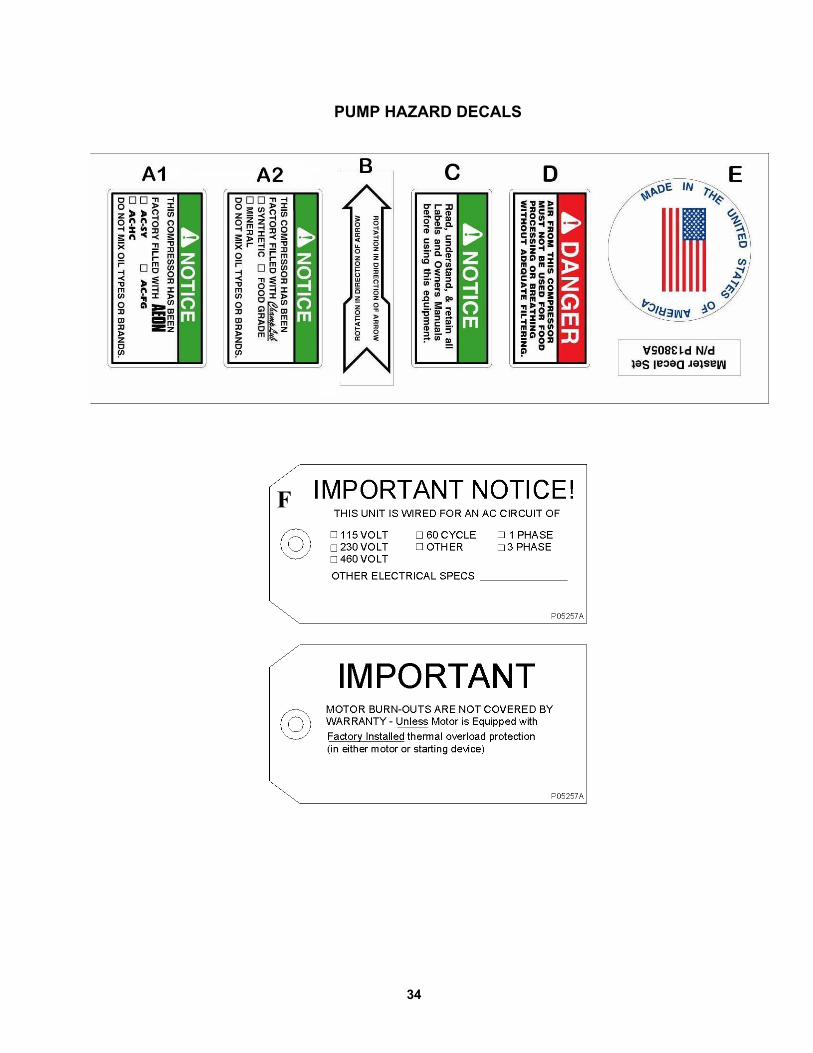
PUMP HAZARD DECAL LISTING
PAGE DESCRIPTION PART NO.
34 PUMP DECAL SHEET – MASTER P13805A NOT USED A1 NOTICE - Lubricants A2 DECAL – Rotation Direction B NOTICE – Read and Retain Manuals C DANGER – Breathing Air D DECAL – Made in the United States of America E IMPORTANT NOTICE – Motor Burn-Outs F
P14677A

33
UNIT HAZARD DECALS
34
PUMP HAZARD DECALS
F

35
RECORD OF MAINTENANCE SERVICE DAILY • CHECK OIiL LEVEL • DRAIN MOISTURE FROM TANK
WEEKLY • CLEAN FILTER • CLEAN COMPRESSOR • CHECK V-BELTS
MONTHLY • INSPECT AIR SYSTEM
EVERY 3 MONTHS • CHANGE OIL • INSPECT VALVE ASSEMBLIES • TIGHTEN ALL FASTENERS • TEST PRESSURE RELIEF VALVE

www.championpneumatic.com Champion 1301 North Euclid Avenue Princeton, Illinois 61356 USA Phone (815) 875-3321 Fax (815) 872-0421 E-mail: [email protected] Plants in Princeton, IL, and Manteca, CA Due to Champion=s continuing product development program, specifications and materials are subject to change without notice or obligation
Copyright 8 2004 Gardner Denver, Inc. Printed in U.S.A.
FOR PARTS: REFER TO PARTS DEPOT LIST ACCOMPANYING THIS MANUAL.
Related Documents